illustration proposée pour une page de gardeillustration ... · thales electron devices gmbh, ulm...
TRANSCRIPT

Thales Electron Devices GmbH, Ulm
Illustration proposée pour une page de garde
Illustration proposée pour une page de garde
Defence Broadcast Radiology Science & industryTelecomsSpace
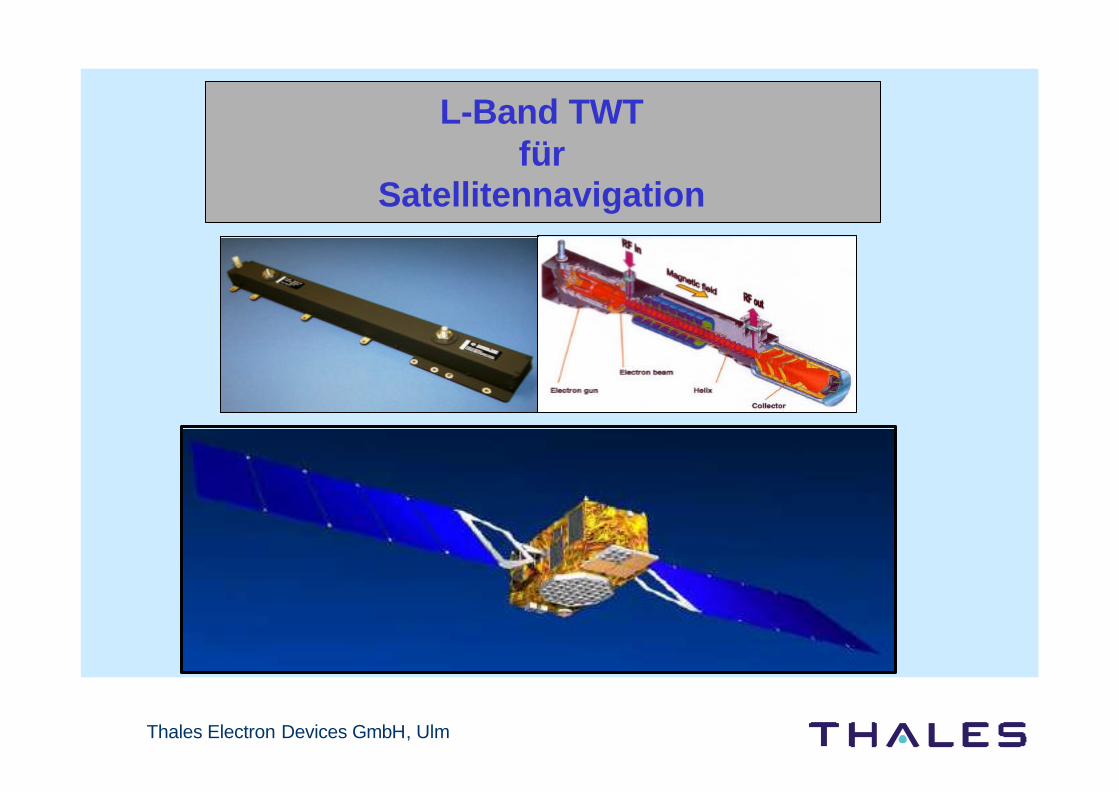
2.Raumfahrt-Technologie-Tage 2003L-Band Wanderfeldröhre für
SatellitennavigationErnst Bosch5. Nov 2003
Thales Electron Devices GmbH, Ulm
L-Band TWTfür
Satellitennavigation

3
Dat
um/D
atei
nahm
e/A
utor
Thales Electron Devices GmbH, Ulm
Inhalt
p Einleitung / Motivation / Anforderung
p Erfahrung /Heritage
p Entwicklungsschritte
p Tests & Ergebnisse
p Vorteile L - Band TWT/ TWTA für Satellitennavigation-damit auch für Galileo
p Zusammenfassung / Ausblick

4
Dat
um/D
atei
nahm
e/A
utor
Thales Electron Devices GmbH, Ulm
Motivation
Motivation L-BandVerstärker für Navigation
Gute Heritage von TEDG bei L-und S-Band Verstärkern
Deutlich gesteigerte Leistungsdaten bei der S-Band Röhre,Übertragung auf L-Band TWT ist in Bearbeitung
sehr hohe Zuverläßigkeit ( fit rate )
Wachsender Markt für die Navigationsanwendung

5
Dat
um/D
atei
nahm
e/A
utor
Thales Electron Devices GmbH, Ulm
Wirkungsgrad: maximal, damit Gesamtleistung bei Kleinsatelliten ausreicht
Ausgangsleistung: von 60 W bis weit über 100 Watt
Bandbreite: große Bandbreite über das ganzeNavigationsband ermöglicht flexiblen Einsatz
Signalstabilität: geringe Variation bei äußeren Einflüssen ( Temperatur , Spannungvariationen )
Kritische Parameter für ein Navigationssystem
Anforderung für Navigation

6
Dat
um/D
atei
nahm
e/A
utor
Thales Electron Devices GmbH, Ulm
Ausgangsleistung: keine Limitierung, bis 150 W,qualifiziert, bis 250 W entwickelt
Bandbreite: bis 400 MHzerlaubt flexiblen Einsatz, auch Mehrträgerbetrieb möglich
Wirkungsgrad: abhängig von der Bandbreite bis 64 % (Röhre) als Verstärker bis 58 %
Signalstabilität: sehr geringer Einfluß, übertrifft die Anforderung bei weitem
Gewicht/Größe bedingt durch die Frequenz -schwerer als SSPA
Wie verhält sich ein Wanderfeldröhrenverstärker gegenüberdiesen Anforderungen?
Anforderungen für Navigation
+
+
++
7
Dat
um/D
atei
nahm
e/A
utor
Thales Electron Devices GmbH, Ulm
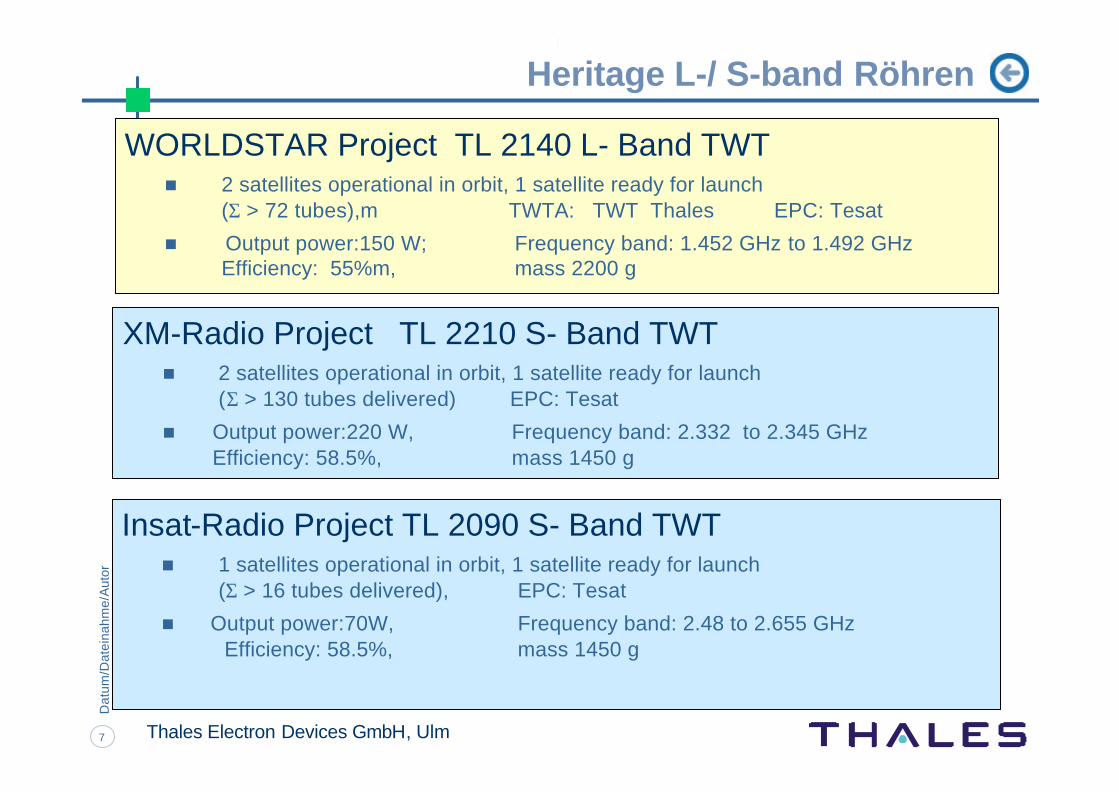
Heritage L-/ S-band Röhren
WORLDSTAR Project TL 2140 L- Band TWTn 2 satellites operational in orbit, 1 satellite ready for launch
(Σ > 72 tubes),m TWTA: TWT Thales EPC: Tesat
n Output power:150 W; Frequency band: 1.452 GHz to 1.492 GHzEfficiency: 55%m, mass 2200 g
XM-Radio Project TL 2210 S- Band TWTn 2 satellites operational in orbit, 1 satellite ready for launch
(Σ > 130 tubes delivered) EPC: Tesat
n Output power:220 W, Frequency band: 2.332 to 2.345 GHzEfficiency: 58.5%, mass 1450 g
Insat-Radio Project TL 2090 S- Band TWTn 1 satellites operational in orbit, 1 satellite ready for launch
(Σ > 16 tubes delivered), EPC: Tesat
n Output power:70W, Frequency band: 2.48 to 2.655 GHz Efficiency: 58.5%, mass 1450 g

8
Dat
um/D
atei
nahm
e/A
utor
Thales Electron Devices GmbH, Ulm
Heritage L-/ S-band Röhren
150 W L-band TWT TL 2140
TNC adapter
SMA adapter
66 mm (including footprint)
Total length: 634 mm77 mm
Mass: 2250 g
Qualification statusTemperature range: -30°C to + 85°C (non operating)
-10°C to + 85°C (operating)Vibration: 18 grms (random, perpendicular)Shock: 480 g (limitation by test equipment)Tube in life test: no critical event for 45000 hours

9
Dat
um/D
atei
nahm
e/A
utor
Thales Electron Devices GmbH, Ulm
L-band tube 150 W
S-band tube 220 W
S-band tube 220 W
S-band tube 70 W
Improved L-band tube
Eta=55 % BW=40 MHz
Eta=58 % BW=14 MHz
Eta=65 % BW=200 MHz
60 / 150 / 250 W , Eff > 60 % BW up to 400 MHz
Eta=58 % BW=175 MHz
Eta and bandw
idth adaptationC-band Ku-band
1996
1998
-2000
2002
2003
The way to improve L-Band TWTs

10
Dat
um/D
atei
nahm
e/A
utor
Thales Electron Devices GmbH, Ulm
Test campaign
Results of the improved L-Band Tubes
Different Power classes from
60-80 Watt optimised for Broad Band ( total navigation band 1.1 to 1.6 GHz)
120-150 Watt optimised for 1.4 to 1.6 GHz( high power band for Galileo)
250 Watt as a high power tube

11
Dat
um/D
atei
nahm
e/A
utor
Thales Electron Devices GmbH, Ulm
120 to 150 Watt Tube
110 W
120 W
130 W
140 W
150 W
160 W
1,550 GHz 1,600 GHz
60 %
62 %
64 %
66 %
68 %
70 %
Output Power Efficiency

12
Dat
um/D
atei
nahm
e/A
utor
Thales Electron Devices GmbH, Ulm
120 to 150 Watt Tube
110 W120 W130 W140 W150 W160 W
1,450 GHz 1,500 GHz 1,550 GHz 1,600 GHz 1,650 GHz
Frequency
Ou
tpu
t P
ow
er
60 %62 %64 %66 %68 %70 %
Output Power Efficiency
Phase shift: < 45 degAM/PM conversion coefficient: < 3 deg/dBGain in Saturation up to 50 dB

13
Dat
um/D
atei
nahm
e/A
utor
Thales Electron Devices GmbH, Ulm
Broad Band Tube
40 W
50 W
60 W
70 W
80 W
90 W
100 W
1,10 GHz 1,20 GHz 1,30 GHz 1,40 GHz 1,50 GHz 1,60 GHz 1,70 GHz
Frequency
Ou
tpu
t Po
wer
E5a/b E6 L1
Phase Shift: 18 degEff.> 55 %
Saturation
Phase Shift: 35 degEff > 52 %
Phase Shift: 25 degEff > 53 %
Output Power in Broad Band adjustment

14
Dat
um/D
atei
nahm
e/A
utor
Thales Electron Devices GmbH, Ulm
Test campaign
Additional Measurement performed on L-Band tube toprove the navigation requirements
o modulation tests
o group delay measurements versus temperature and voltage (typical EPC stability values used)
o noise measurements
o Multi carrier measurements
o Flexible Power setting only with anode voltage

15
Dat
um/D
atei
nahm
e/A
utor
Thales Electron Devices GmbH, Ulm
Test campaign
Conclusion after all Tests:
All performed tests â all needed power levels covered by a highly efficient tubeâ different modulation schemes
â non - linear behaviour sensitivity â noise and multi carrier operation â flexible power adjustment by anode voltage
confirm,that the TWT test results are
excellent(better than the known requirements )

16
Dat
um/D
atei
nahm
e/A
utor
Thales Electron Devices GmbH, Ulm
Advantageto use a
Travelling Wave Tubefor
Navigation Systemas
Galileo

17
Dat
um/D
atei
nahm
e/A
utor
Thales Electron Devices GmbH, Ulm
Advantage to use a Travelling Wave Tube
n Output Power Flexibility
n No limitation in power: 150 W - or up to 250 W, if needed
n Bandwidth
n The bandwidth of the L-Band TWT is 200 to 400 MHz.n Fewer redundant amplifiers
n Multi carrier operation
n 2 carrier operation is feasible and tested (for E5+ E6)n less redundant tubes (5 TWTA compared to 8 SSPA )

18
Dat
um/D
atei
nahm
e/A
utor
Thales Electron Devices GmbH, Ulm
Advantage to use a Travelling Wave Tube
n Group delay stability over temperature
n Very low sensitivity - ideal for navigation systems
n has been tested under the critical conditions of temperature variation (up to 60 °C) and supply voltage stability.
n Group delay slope will be marginal (possible compensation )
n High power tubesn TED is manufacturing S- and Ku- Band tubes up to 220 Watt. The tubes are
designed to operate without any degradation for more than 15 years.
n Qualified L-band TWT produced by TEDn qualified up to 150 W output power.n -10 to +85°C in operational conditions and the EPC from -10 to + 65 °C.n Mechanical: random vibration up to 18 grms and pyro shock

19
Dat
um/D
atei
nahm
e/A
utor
Thales Electron Devices GmbH, Ulm
Advantage to use a Travelling Wave Tube
n Outstanding Heritage and Experience
n more than 30 years of experience for space TWTs (>5000 TWTs)
n TED has the experience to manage such an important and big project either asTWT or TWTA supplier (responsibility for the integration of TWT and EPC).
n Proven Reliabilityn accumulated operational time in orbit exceeds 3 Million hours.
n Tube designn all requirements and design goals according valued ESA PSS Space norms no
change necessary
n Advantage to use Dual EPC or with Lineariser + Champn additional mass reduction ( redundancy plan)n additional improvement for the linearity and therefore power consumption

20
Dat
um/D
atei
nahm
e/A
utor
Thales Electron Devices GmbH, Ulm
Conclusion
THALES - TEDGL-Band Travelling Wave
Tube Amplifiersprovide
an attractive solution forNavigation System
Galileo
Thales Electron Devices GmbH, Ulm
Thank you for your attentionQuestion / Answer