iii unit levelling and its applications 1. explain the
TRANSCRIPT
III UNIT LEVELLING AND ITS APPLICATIONS
1. Explain the different types of levels ( Levelling Instrument) with neat
sketches?
Dumpy Level, Wye Level, Reversible Level, Tilting Level, and Digital level
1. Dumpy level:
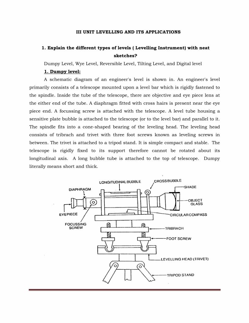
A schematic diagram of an engineer's level is shown in. An engineer's level
primarily consists of a telescope mounted upon a level bar which is rigidly fastened to
the spindle. Inside the tube of the telescope, there are objective and eye piece lens at
the either end of the tube. A diaphragm fitted with cross hairs is present near the eye
piece end. A focussing screw is attached with the telescope. A level tube housing a
sensitive plate bubble is attached to the telescope (or to the level bar) and parallel to it.
The spindle fits into a cone-shaped bearing of the leveling head. The leveling head
consists of tribrach and trivet with three foot screws known as leveling screws in
between. The trivet is attached to a tripod stand. It is simple compact and stable. The
telescope is rigidly fixed to its support therefore cannot be rotated about its
longitudinal axis. A long bubble tube is attached to the top of telescope. Dumpy
literally means short and thick.
Telescope : used to sight a staff placed at desired station and to read staff reading
distinctly.
Diaphragm : holds the cross hairs (fitted with it).
Eye piece : magnifies the image formed in the plane of the diaphragm and thus to
read staff during leveling.
Level Tube : used to make the axis of the telescope horizontal and thus the line of
sight.
Leveling screws : to adjust instrument (level) so that the line of sight is horizontal for
any orientation of the telescope.
Tripod stand : to fix the instrument (level) at a convenient height of an observer.
2. Wye level:
The essential difference between the dumpy level and the Wye level is that in the
former case the telescope is fixed to the spindle while in the Wye level, the telescope is
carried in two vertical Wye supports. The Wye support consists of curved clips.The
clips are raised, the telescope can be rotated in the Wyes, or removed and turned end
for end. When the clips are fastened the telescope is held from turning about its axis
by a lug on one of the clips. The bubble tube may be attached either to the telescope
or to the stage carrying the wyes.
3. Reversible level:
A reversible level combines the features of bioth the dumpy level and the Wye level.
The telescope is supported by two rigid sockets into which the telescope can be
introduced from either end and then fixed in position by a screw. The sockets are
rigidly connected to the spindle through a stage.
4. Tilting level :
It consists of a telescope attached with a level tube which can be tilted within few
degrees in vertical plane by a tilting screw.
The main peculiarity of this level is that the vertical axis need not be truly vertical,
since the line of collimation is not perpendicular to it. The line of collimation, is,
however, made horizontal for each pointing of telescope by means of tilting screw. It is
mainly designed for precise leveling work.

5. Digital level
There are fundamentally two types of automatic levels.
First, the optical one whose distinguishing feature is self-leveling i.e., the instruments
gets approximately leveled by means of a circular spirit level and then it maintains a
horizontal line of sight of its own.
Second, the digital levels whose distinguishing features are automatic leveling, reading
and recording.
2. Explain, in details, the different types of leveling.
I ) Direct Leveling : Direct measurement, precise, most commonly used;
Types:
(1) Simple leveling : One set up of level. To find elevation of points. When the
difference of level between two points is determined by setting the leveling instrument
midway between the points , the process is called simple leveling.
2. Differential leveling :
Differential leveling is adopted when : (i) the points are at a great difference apart, (ii)
the difference of elevation between the points is large, (iii) there are obstacles between
the points. To find elevation of non-intervisible points.
This method is called compound leveling or continuous leveling.
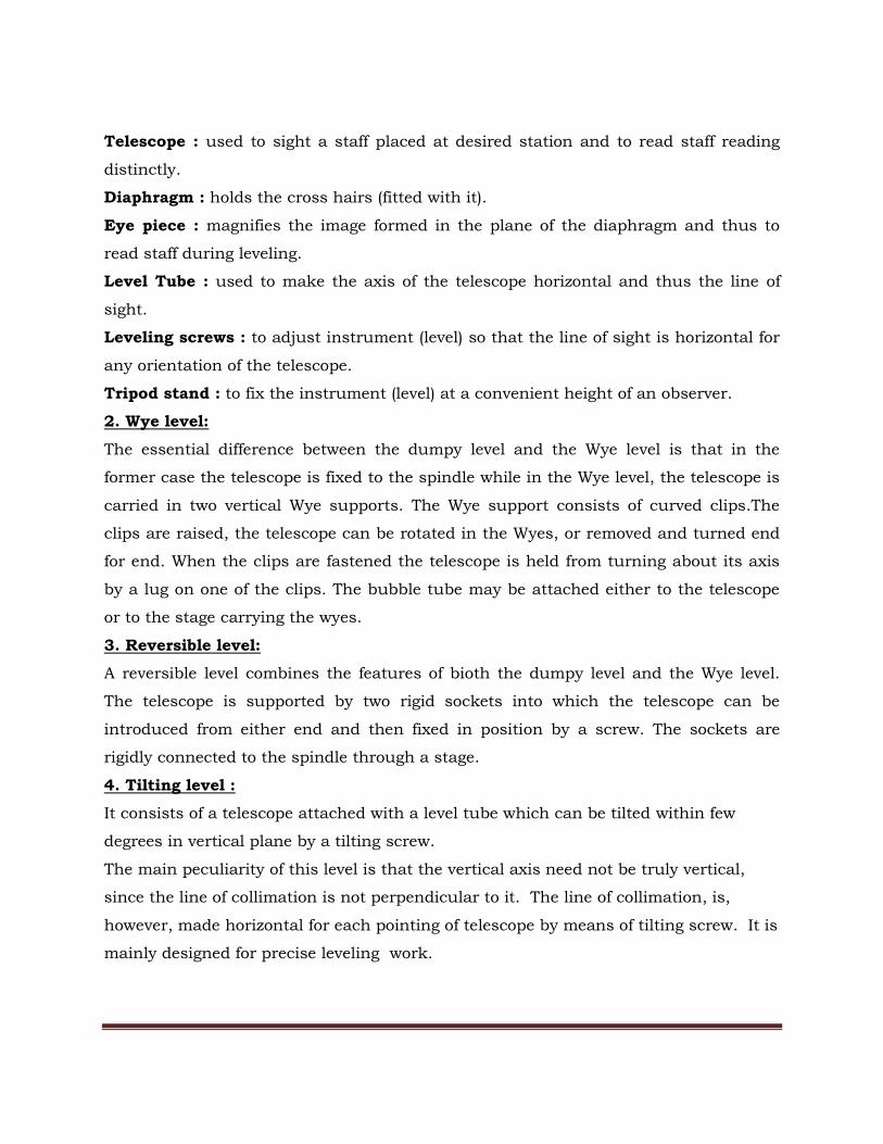
3. Fly leveling :
When differential leveling is done in order to connect a bench mark to the starting
point of the alignment of any project, it is called fly leveling. Fly leveling is done to
connect the BM to any intermediate point of the alignment for checking the accuracy
of the work. Only back sight and fore sight readings are taken at every set up of the
level and no distances are measured along the direction of leveling.
Low precision, to find/check approximate level, generally used during reconnaissance
survey.
4. Precise leveling : Precise form of differential leveling.
5. Profile leveling : Finding of elevation along a line and its cross section.
6. Reciprocal leveling : Along a river or pond. Two level simultaneously used, one at
either end.
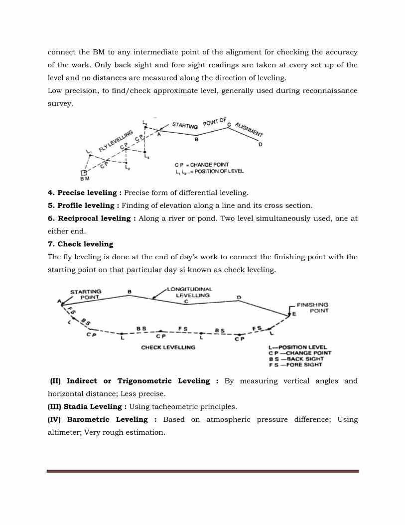
7. Check leveling
The fly leveling is done at the end of day’s work to connect the finishing point with the
starting point on that particular day si known as check leveling.
(II) Indirect or Trigonometric Leveling : By measuring vertical angles and
horizontal distance; Less precise.
(III) Stadia Leveling : Using tacheometric principles.
(IV) Barometric Leveling : Based on atmospheric pressure difference; Using
altimeter; Very rough estimation.

3. Mention the differences between height of collimation method and rise and
fall method?
There are two Methods of Levelling:
1. Height of Collimation Method 2. Rise and Fall Method
Sl.No Height of collimation system Rise and fall system
1 It is rapid as it involves few
calculation
It is laborious involving several
calcuation
2 There is no check on the RL of the
intermediate sight
There is a check on the RL of the
intermediate points
3 Errors in the intermediate RLs cannot
be detected.
Errors in the intermediate RLs can
be detected as all the points are
correlated
4 There are two checks on the accuracy
of RL calculation
There are three checks on the
accuracy of RL calculation
5 This system is suitable for
longitudinal leveling where there are a
number of intermediate sights
This system is suitable for fly
leveling where there are no
intermediate sights
4. What is a temporary adjustment? How it is done?
Temporary Adjustment of a Level
At each set up of a level instrument, temporary adjustment is required to be carried
out prior to any staff observation. It involves some well defined operations which are
required to be carried out in proper sequence.
The temporary adjustment of a dumpy level consists of
(1)Setting , (2)Leveling and (3) Focusing .
During Setting, the tripod stand is set up at a convenient height having its head
horizontal (through eye estimation). The instrument is then fixed on the head by
rotating the lower part of the instrument with right hand and holding firmly the upper
part with left hand. Before fixing, the leveling screws are required to be brought in
between the tribrach and trivet. The bull's eye bubble (circular bubble), if present, is
then brought to the centre by adjusting the tripod legs.
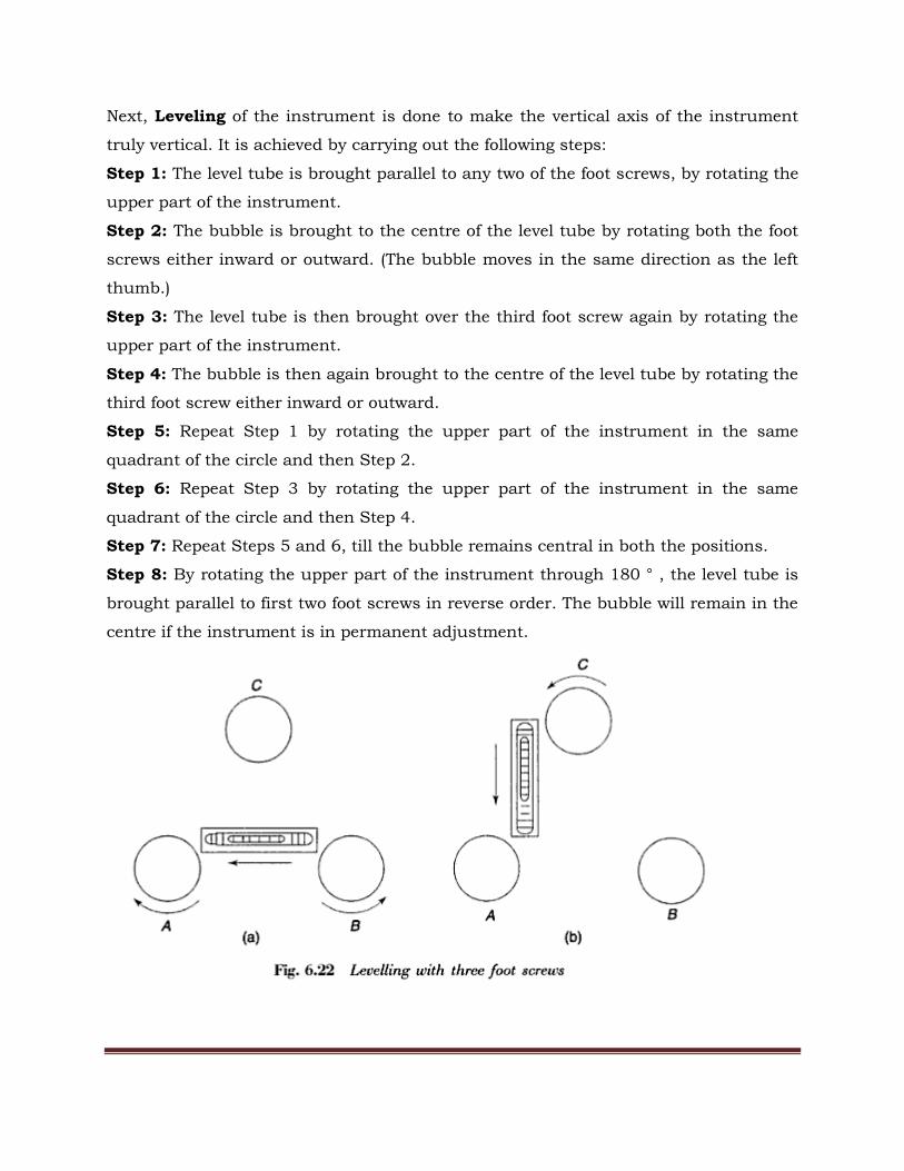
Next, Leveling of the instrument is done to make the vertical axis of the instrument
truly vertical. It is achieved by carrying out the following steps:
Step 1: The level tube is brought parallel to any two of the foot screws, by rotating the
upper part of the instrument.
Step 2: The bubble is brought to the centre of the level tube by rotating both the foot
screws either inward or outward. (The bubble moves in the same direction as the left
thumb.)
Step 3: The level tube is then brought over the third foot screw again by rotating the
upper part of the instrument.
Step 4: The bubble is then again brought to the centre of the level tube by rotating the
third foot screw either inward or outward.
Step 5: Repeat Step 1 by rotating the upper part of the instrument in the same
quadrant of the circle and then Step 2.
Step 6: Repeat Step 3 by rotating the upper part of the instrument in the same
quadrant of the circle and then Step 4.
Step 7: Repeat Steps 5 and 6, till the bubble remains central in both the positions.
Step 8: By rotating the upper part of the instrument through 180 ° , the level tube is
brought parallel to first two foot screws in reverse order. The bubble will remain in the
centre if the instrument is in permanent adjustment.
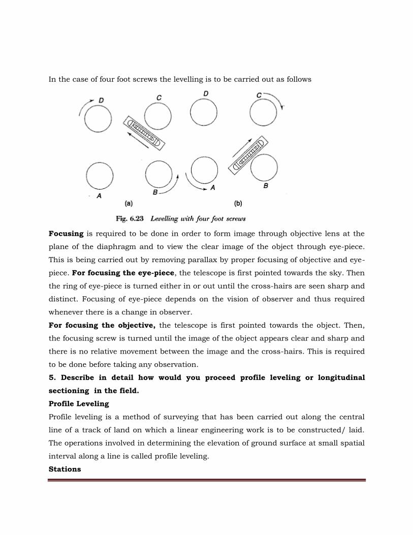
In the case of four foot screws the levelling is to be carried out as follows
Focusing is required to be done in order to form image through objective lens at the
plane of the diaphragm and to view the clear image of the object through eye-piece.
This is being carried out by removing parallax by proper focusing of objective and eye-
piece. For focusing the eye-piece, the telescope is first pointed towards the sky. Then
the ring of eye-piece is turned either in or out until the cross-hairs are seen sharp and
distinct. Focusing of eye-piece depends on the vision of observer and thus required
whenever there is a change in observer.
For focusing the objective, the telescope is first pointed towards the object. Then,
the focusing screw is turned until the image of the object appears clear and sharp and
there is no relative movement between the image and the cross-hairs. This is required
to be done before taking any observation.
5. Describe in detail how would you proceed profile leveling or longitudinal
sectioning in the field.
Profile Leveling
Profile leveling is a method of surveying that has been carried out along the central
line of a track of land on which a linear engineering work is to be constructed/ laid.
The operations involved in determining the elevation of ground surface at small spatial
interval along a line is called profile leveling.
Stations
The line along which the profile is to be run is to be marked on the ground before
taking any observation. Stakes are usually set at some regular interval which depends
on the topography, accuracy required, nature of work, scale of plotting etc. It is
usually taken to be 10 meter. The beginning station of profile leveling is termed as
0+00. Points at multiples of 100m from this point are termed as full stations.
Intermediate points are designated as pluses.
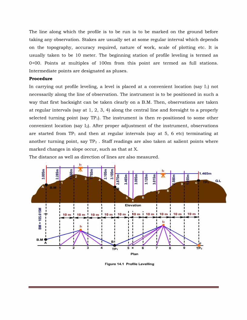
Procedure
In carrying out profile leveling, a level is placed at a convenient location (say I1) not
necessarily along the line of observation. The instrument is to be positioned in such a
way that first backsight can be taken clearly on a B.M. Then, observations are taken
at regular intervals (say at 1, 2, 3, 4) along the central line and foresight to a properly
selected turning point (say TP1). The instrument is then re-positioned to some other
convenient location (say I2). After proper adjustment of the instrument, observations
are started from TP1 and then at regular intervals (say at 5, 6 etc) terminating at
another turning point, say TP2 . Staff readings are also taken at salient points where
marked changes in slope occur, such as that at X.
The distance as well as direction of lines are also measured.
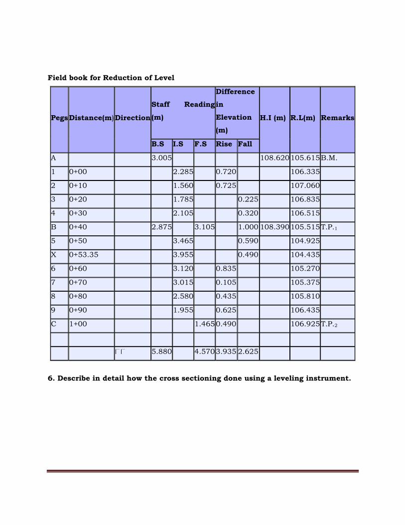
Field book for Reduction of Level
Pegs Distance(m) Direction
Staff Reading
(m)
Difference
in
Elevation
(m)
H.I (m) R.L(m) Remarks
B.S I.S F.S Rise Fall
A 3.005 108.620 105.615 B.M.
1 0+00 2.285 0.720 106.335
2 0+10 1.560 0.725 107.060
3 0+20 1.785 0.225 106.835
4 0+30 2.105 0.320 106.515
B 0+40 2.875 3.105 1.000 108.390 105.515 T.P.1
5 0+50 3.465 0.590 104.925
X 0+53.35 3.955 0.490 104.435
6 0+60 3.120 0.835 105.270
7 0+70 3.015 0.105 105.375
8 0+80 2.580 0.435 105.810
9 0+90 1.955 0.625 106.435
C 1+00 1.465 0.490 106.925 T.P.2
5.880 4.570 3.935 2.625
6. Describe in detail how the cross sectioning done using a leveling instrument.

Cross Sectioning
In many projects, terrain information transverse to the longitudinal section (through
profile leveling) is also required such as for highways, railways, canals etc. In those
cases, surveying is carried out at right angle to the central line, generally, at regular
interval is being carried out and is termed as cross- sectioning. If, for any reason, a
cross-section is run in any other direction, the angle with the centre line is required to
be noted. The observations are then recorded as being to the left or right of the centre
line. The notes of the readings are maintained as shown in for taking a cross-section
along the stake point 4. Reduction of levels, Plotting etc. can be done as in case of
profile leveling.
Pegs Distance(m) Direction
Staff reading (m) Difference in
elevation (m) H.I (m) R.L (m) Remark
B.S. I.S. F.S. Rise
(m) Fall (m)
A 3.005 108.620 105.615 B.M.
:
4 0+30 2.105 0.320 106.515 0m
1.850 106.770 2m left
1.725 106.895 4m left
1.680 106.940 6m left
1.985 106.635 2m
right
1.875 106.745 4m

right
1.780 106.840 6m
right
B 0+40 2.875 3.105 1.000 108.390 105.515 T.P.1
:
7. Derive the value of curvature and refraction corrections.
Curvature correction:
For long sights , the curvature of the earth affects staff readings . The line of sight
is horizontal , but the level lines is curved and parallel to the mean spheroidal
surface of the earth. the vertical distance between the line of sight and thel level
line at a particular place is called the curvature correction. Due to the curvature
objects appear lower than they really are:

Refraction correction
It varies with temperature, terrain and other atmospheric conditions. It is
usually considered to be one seventh times but in opposite nature to the error
due to curvature. To minimize this error, reciprocal observation at the same
instant of time is required to be adopted.In actual field condition, the line of
sight through a level is not straight but it bends downward due to the refraction
of rays of light as it passes through the intervening medium.
Cr= 1/7 × (D2/2R)
8. When is reciprocal leveling done? Describe the method along with a sketch.
In the case of an obstacle like river valley, it is not possible to set the up the level
midway between two points on the opposite banks. In such cases the method of
reciprocal leveling is adopted, which involv3es reciprocal observations from both
banks of the river or valley. Two sets of staff readings are taken by holding the staff on
both banks. In this case it is found that the errors are completely eliminated and the
true difference of level is equal to the mean of the two apparent differences of level.
The principle is explained as follows.
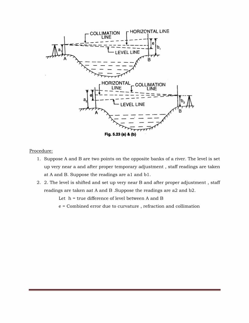
Procedure:
1. Suppose A and B are two points on the opposite banks of a river. The level is set
up very near a and after proper temporary adjustment , staff readings are taken
at A and B. Suppose the readings are a1 and b1.
2. 2. The level is shifted and set up very near B and after proper adjustment , staff
readings are taken aat A and B .Suppose the readings are a2 and b2.
Let h = true difference of level between A and B
e = Combined error due to curvature , refraction and collimation

9. Describe the two peg method of adjustment along with a neat sketch.
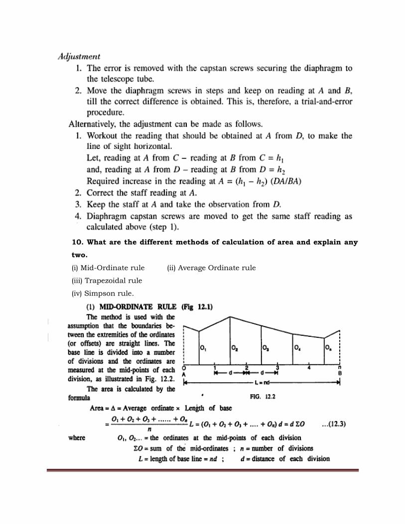
10. What are the different methods of calculation of area and explain any
two.
(i) Mid-Ordinate rule (ii) Average Ordinate rule
(iii) Trapezoidal rule
(iv) Simpson rule.

11. State Trapezidal rule and derive the expressionfor it.

12. State Simpson’s one third rule and derive the expression for it
CONTOURS
13. Explain the uses of contours maps.
Contours provide valuable information about the nature of terrain. This is very
important for selection of sites, determination of catchment area of a drainage basin,
to find intervisibility between stations etc. Some of the salient uses of contours are
described below
Nature of Ground
To visualize the nature of ground along a cross section of interest,
To Locate Route
Contour map provides useful information for locating a route at a given gradient such
as highway, canal, sewer line etc.
Intervisibility between Stations
When the intervisibility between two points can not be ascertained by
inspection of the area, it can be determined using contour map.
To Determine Catchment Area or Drainage Area
The catchment area of a river is determined by using contour map. The watershed line
which indicates the drainage basin of a river passes through the ridges and saddles of
the terrain around the river. Thus, it is always perpendicular to the contour lines. The
catchment area contained between the watershed line and the river outlet is then
measured with a planimeter
Storage capacity of a Reservoir
The storage capacity of a reservoir is determined from contour map. The contour line
indicating the full reservoir level (F.R.L) is drawn on the contour map. The area
enclosed between successive contours are measured by planimeter .The volume of
water between F.R.L and the river bed is finally estimated by using either Trapezoidal
formula or Prismoidal formula.
14. Explain the characteristics of contours.
Characteristics of Contour
The principal characteristics of contour lines which help in plotting or reading a
contour map are as follows:
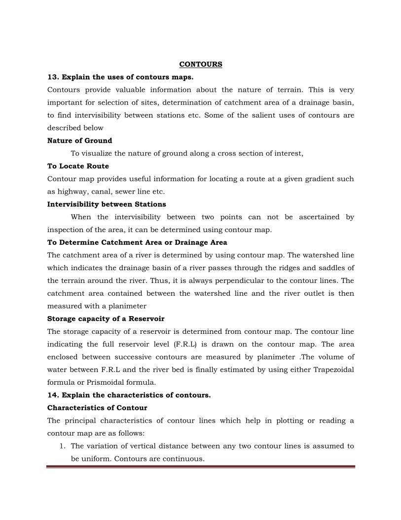
1. The variation of vertical distance between any two contour lines is assumed to
be uniform. Contours are continuous.
(Fig: Contours are continuous)
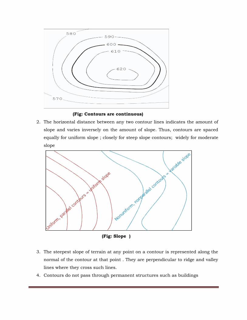
2. The horizontal distance between any two contour lines indicates the amount of
slope and varies inversely on the amount of slope. Thus, contours are spaced
equally for uniform slope ; closely for steep slope contours; widely for moderate
slope
(Fig: Slope )
3. The steepest slope of terrain at any point on a contour is represented along the
normal of the contour at that point . They are perpendicular to ridge and valley
lines where they cross such lines.
4. Contours do not pass through permanent structures such as buildings
5. Contours of different elevations cannot cross each other (caves and overhanging
cliffs are the exceptions).
6. Contours of different elevations cannot unite to form one contour (vertical cliff
is an exception).
7. Contour lines cannot begin or end on the plan.
8. A contour line must close itself but need not be necessarily within the limits of
the map.
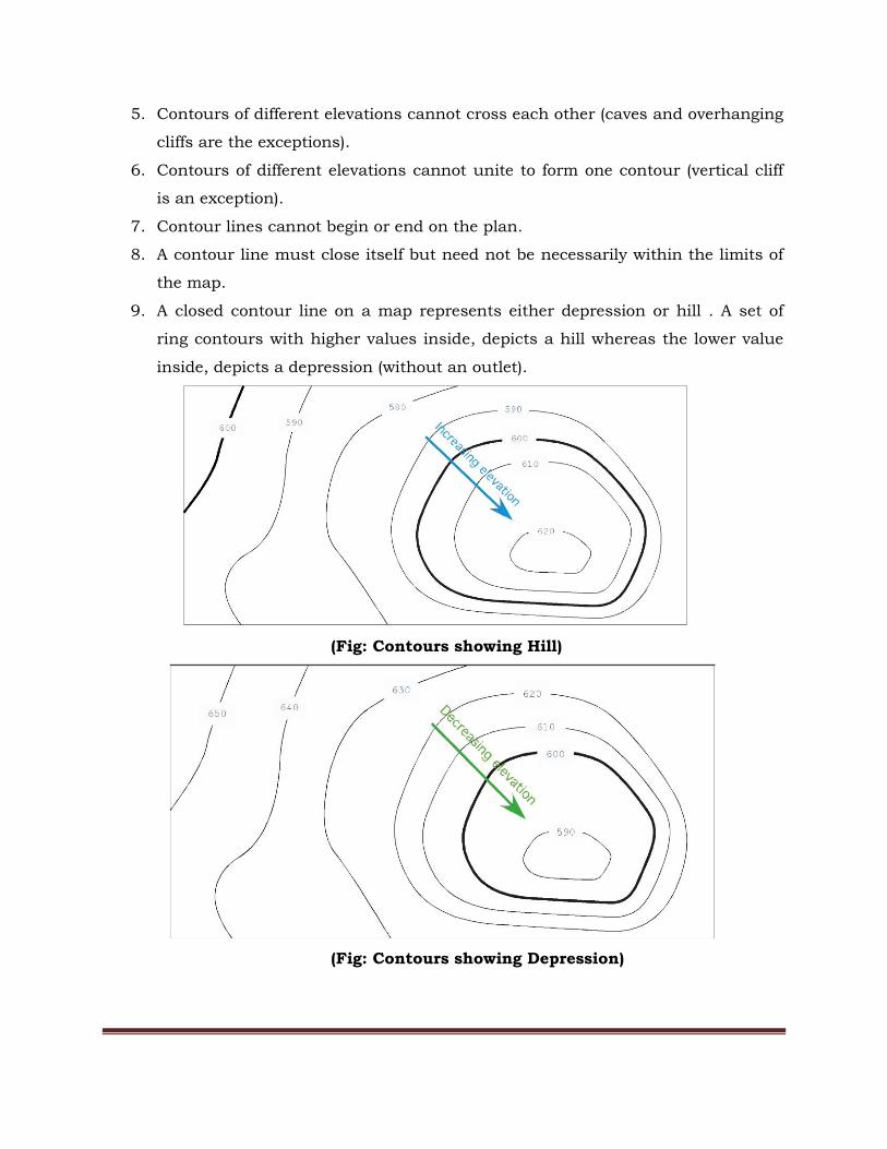
9. A closed contour line on a map represents either depression or hill . A set of
ring contours with higher values inside, depicts a hill whereas the lower value
inside, depicts a depression (without an outlet).
(Fig: Contours showing Hill)
(Fig: Contours showing Depression)

10. Contours deflect uphill at valley lines and downhill at ridge lines. Contour lines in
U-shape cross a ridge and in V-shape cross a valley at right angles. The concavity in
contour lines is towards higher ground in the case of ridge and towards lower
ground in the case of valley
(Fig: Contours showing valley)
(Fig: Contours showing Ridge)
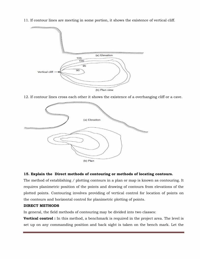
11. If contour lines are meeting in some portion, it shows the existence of vertical cliff.
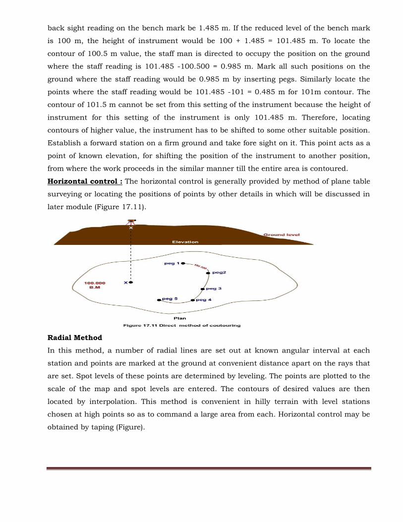
12. If contour lines cross each other it shows the existence of a overhanging cliff or a cave.
15. Explain the Direct methods of contouring or methods of locating contours.
The method of establishing / plotting contours in a plan or map is known as contouring. It
requires planimetric position of the points and drawing of contours from elevations of the
plotted points. Contouring involves providing of vertical control for location of points on
the contours and horizontal control for planimetric plotting of points.
DIRECT METHODS
In general, the field methods of contouring may be divided into two classes:
Vertical control : In this method, a benchmark is required in the project area. The level is
set up on any commanding position and back sight is taken on the bench mark. Let the
back sight reading on the bench mark be 1.485 m. If the reduced level of the bench mark
is 100 m, the height of instrument would be 100 + 1.485 = 101.485 m. To locate the
contour of 100.5 m value, the staff man is directed to occupy the position on the ground
where the staff reading is 101.485 -100.500 = 0.985 m. Mark all such positions on the
ground where the staff reading would be 0.985 m by inserting pegs. Similarly locate the
points where the staff reading would be 101.485 -101 = 0.485 m for 101m contour. The
contour of 101.5 m cannot be set from this setting of the instrument because the height of
instrument for this setting of the instrument is only 101.485 m. Therefore, locating
contours of higher value, the instrument has to be shifted to some other suitable position.
Establish a forward station on a firm ground and take fore sight on it. This point acts as a
point of known elevation, for shifting the position of the instrument to another position,
from where the work proceeds in the similar manner till the entire area is contoured.
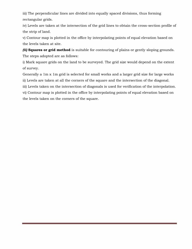
Horizontal control : The horizontal control is generally provided by method of plane table
surveying or locating the positions of points by other details in which will be discussed in
later module (Figure 17.11).
Radial Method
In this method, a number of radial lines are set out at known angular interval at each
station and points are marked at the ground at convenient distance apart on the rays that
are set. Spot levels of these points are determined by leveling. The points are plotted to the
scale of the map and spot levels are entered. The contours of desired values are then
located by interpolation. This method is convenient in hilly terrain with level stations
chosen at high points so as to command a large area from each. Horizontal control may be
obtained by taping (Figure).

16.Explain the In Direct methods of contouring.
INDIRECT METHODS
In this method, points are located in the field, generally as corners of well-shaped
geometrical figures such as squares, rectangles, and spot levels are determined. Elevations
of desired contours are interpolated in between spot levels and contour lines are drawn by
joining points of equal elevation.
Indirect methods are less expensive, less time consuming and less tedious as compared to
the direct method. These methods are commonly employed in small scale surveys of large
areas or during mapping of irregular surface or steep slope. There are THREE different
ways usually employed for indirect method of contouring:
(i) Cross section method is most suitable for preparing contour maps for road works, rail
works, canals etc.
Typically, this type of land has a very long strip but narrow width.
The steps involved are as follows:
i) The centre line of the strip of land is first marked
ii) Lines perpendicular to the longitudinal strip are marked dividing the strip into equal
sections
iii) The perpendicular lines are divided into equally spaced divisions, thus forming
rectangular grids.
iv) Levels are taken at the intersection of the grid lines to obtain the cross-section profile of
the strip of land.
v) Contour map is plotted in the office by interpolating points of equal elevation based on
the levels taken at site.
(ii) Squares or grid method is suitable for contouring of plains or gently sloping grounds.
The steps adopted are as follows:
i) Mark square grids on the land to be surveyed. The grid size would depend on the extent
of survey.
Generally a 1m x 1m grid is selected for small works and a larger grid size for large works
ii) Levels are taken at all the corners of the square and the intersection of the diagonal.
iii) Levels taken on the intersection of diagonals is used for verification of the interpolation.
vi) Contour map is plotted in the office by interpolating points of equal elevation based on
the levels taken on the corners of the square.
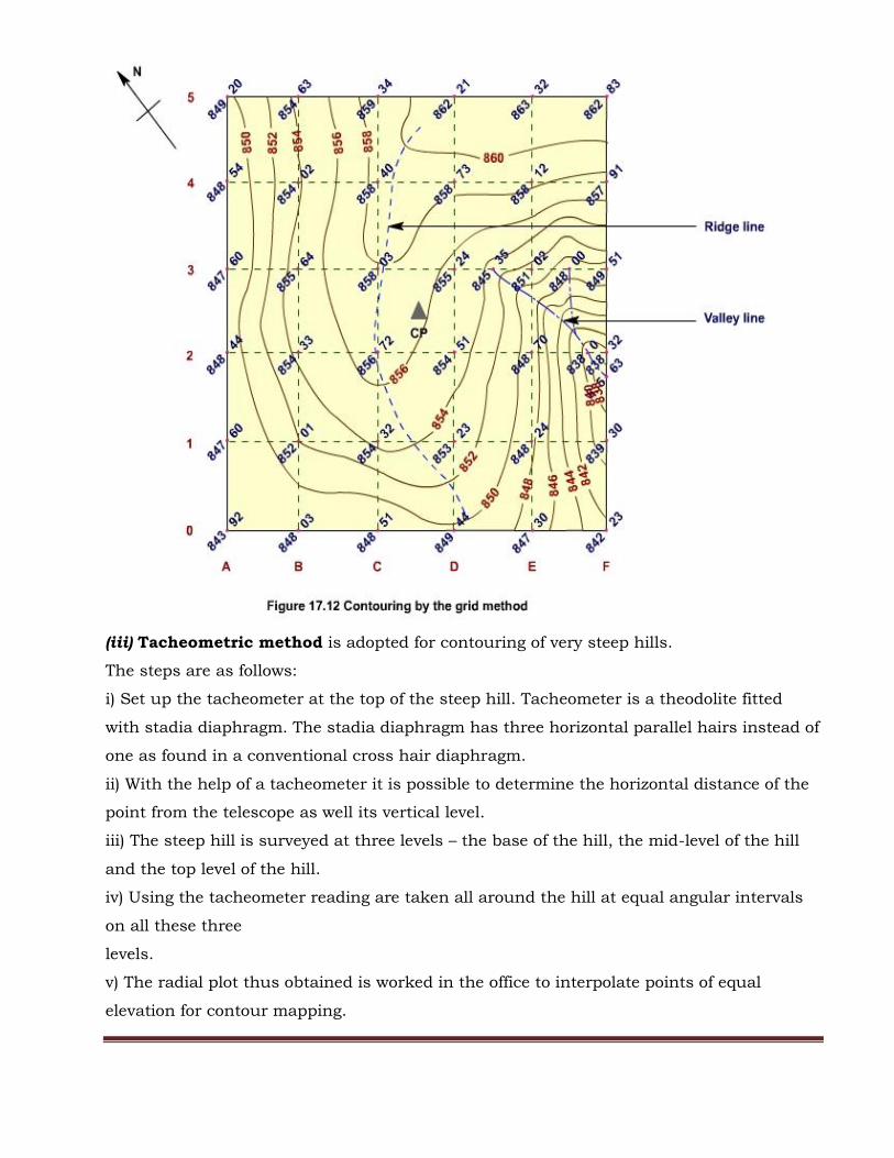
(iii) Tacheometric method is adopted for contouring of very steep hills.
The steps are as follows:
i) Set up the tacheometer at the top of the steep hill. Tacheometer is a theodolite fitted
with stadia diaphragm. The stadia diaphragm has three horizontal parallel hairs instead of
one as found in a conventional cross hair diaphragm.
ii) With the help of a tacheometer it is possible to determine the horizontal distance of the
point from the telescope as well its vertical level.
iii) The steep hill is surveyed at three levels – the base of the hill, the mid-level of the hill
and the top level of the hill.
iv) Using the tacheometer reading are taken all around the hill at equal angular intervals
on all these three
levels.
v) The radial plot thus obtained is worked in the office to interpolate points of equal
elevation for contour mapping.

17. Compare Direct and Indirect methods.
Sl.No DIRECT METHOD INDIRECT METHOD
1 Very accurate but slow and tedious Not very accurate but quicker and
less tedious.
2 Expensive Reasonable cost
3
Appropriate for small projects requiring
high accuracy, e.g., layout of building,
factory, structural foundations, etc.
Suitable for large projects requiring
moderate to low accuracy, e.g.,
layout of highway, railway, canal,
etc.
4 More suitable for low undulating
terrain. Suitable for hilly terrain.
5 Calculations need to be carried out in
thefield
Calculation in the field is not
mandatory.
6 After contouring, calculation cannot be
checked.
Calculations can be checked as and
when needed
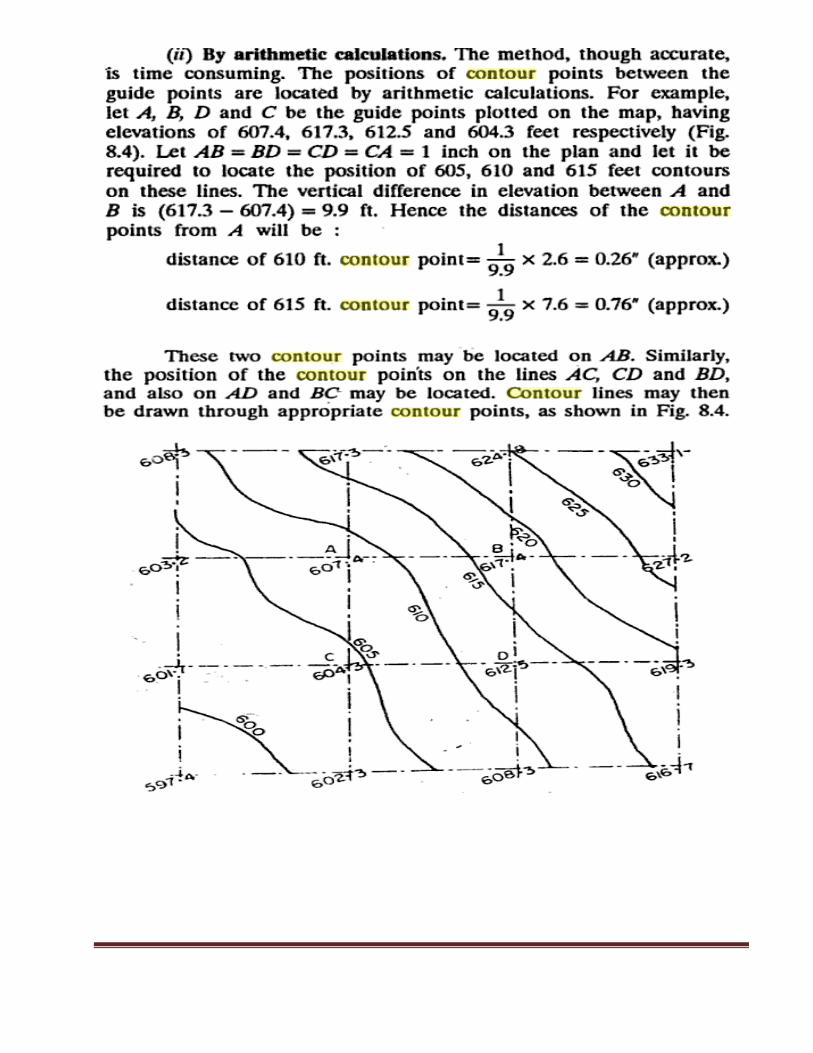
18. Explain Interpolation of contours in detail.
Interpolation of the contours is the process of spacing the contours proportionately
between the plotted ground points established by indirect methods. The methods of
interpolation are based on the assumption that the slope of ground between the two
points is uniform.
The chief methods of interpolation are (i) By estimation (ii) By arithmetic calculation (iii) By
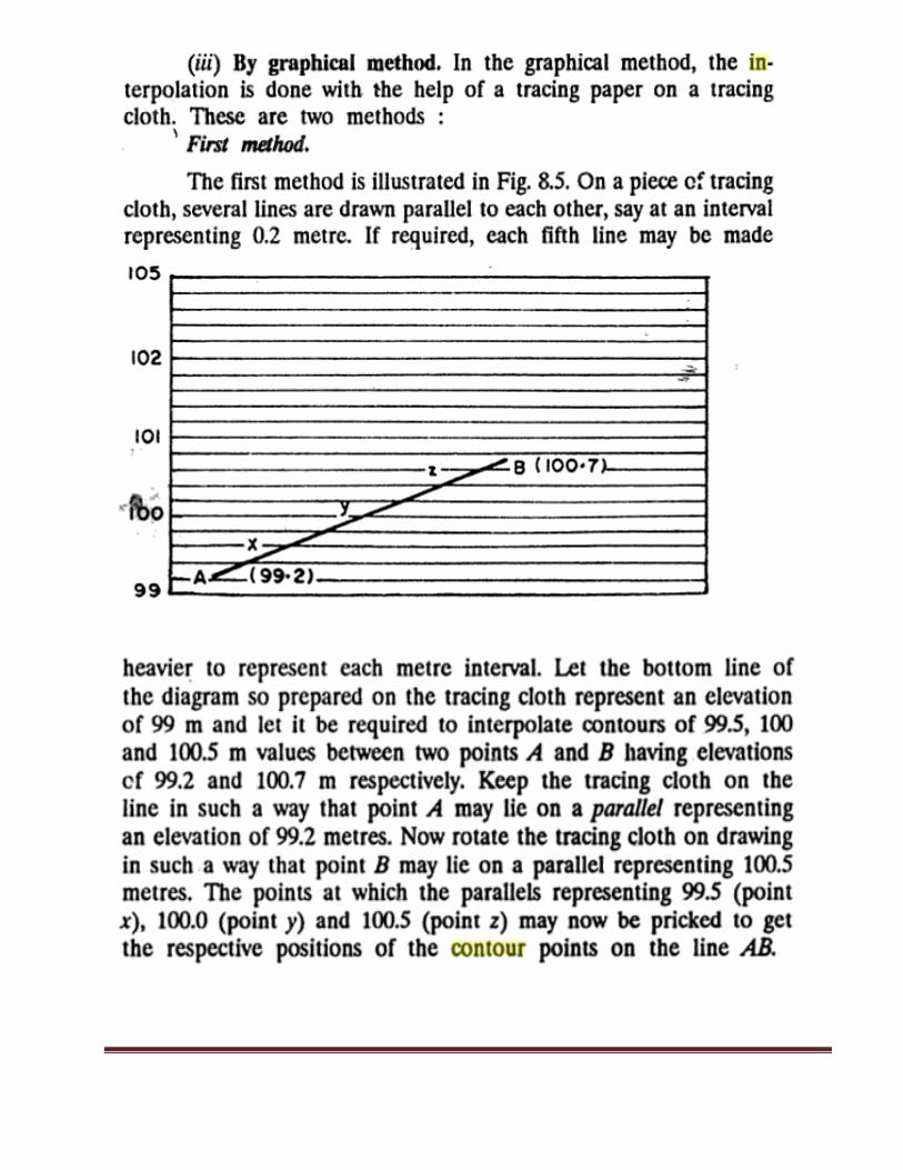
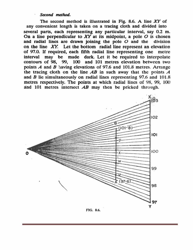
graphical method.
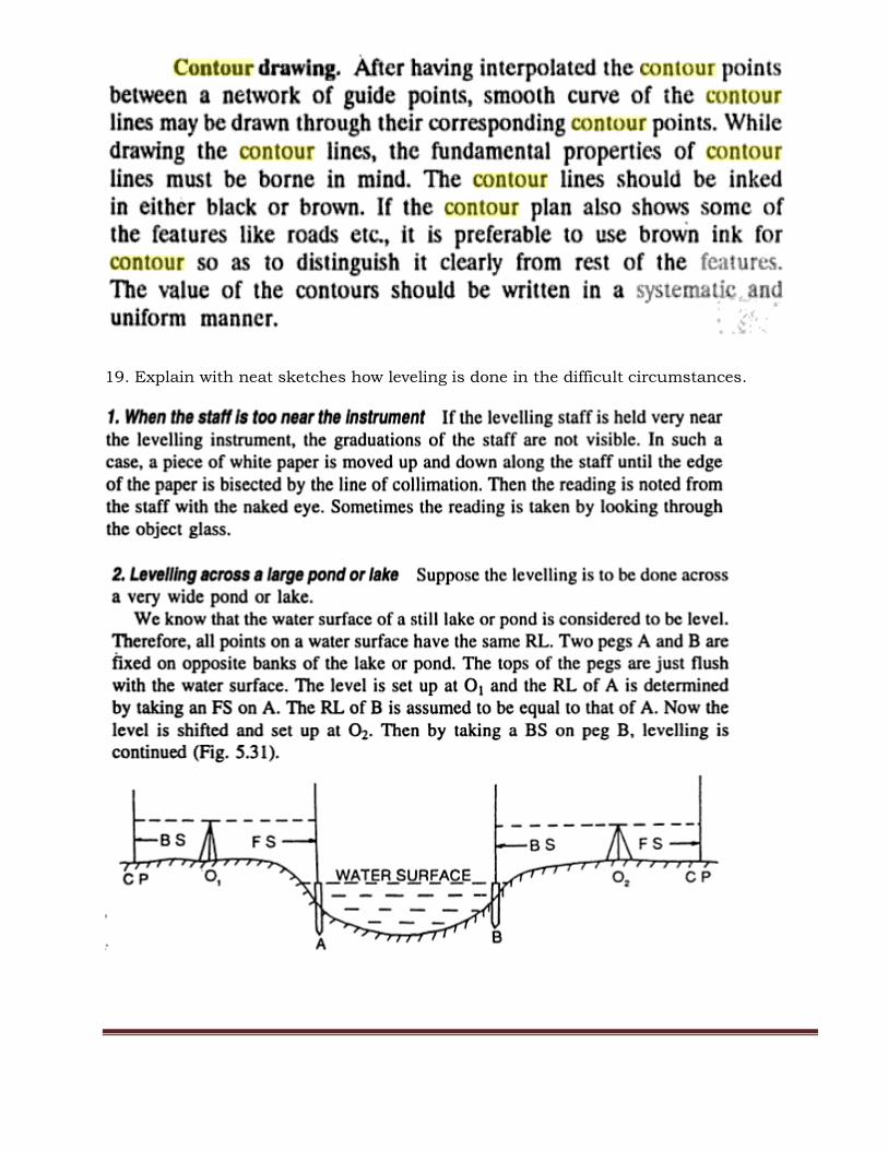
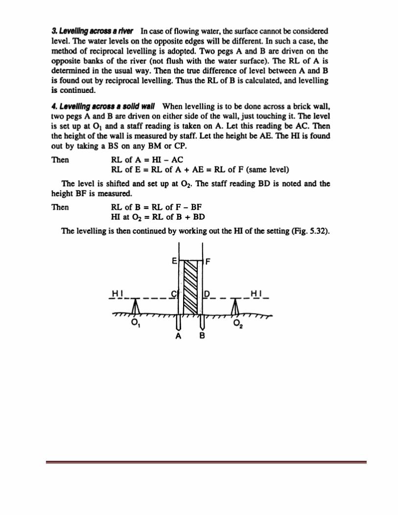
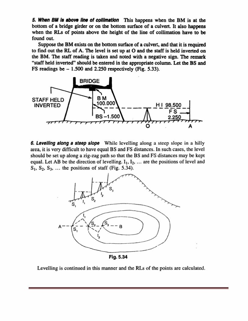
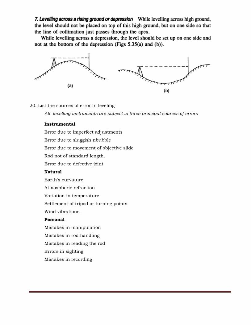
19. Explain with neat sketches how leveling is done in the difficult circumstances.
20. List the sources of error in leveling
All levelling instruments are subject to three principal sources of errors
Instrumental
Error due to imperfect adjustments
Error due to sluggish nbubble
Error due to movement of objective slide
Rod not of standard length.
Error due to defective joint
Natural
Earth’s curvature
Atmospheric refraction
Variation in temperature
Settlement of tripod or turning points
Wind vibrations
Personal
Mistakes in manipulation
Mistakes in rod handling
Mistakes in reading the rod
Errors in sighting
Mistakes in recording