ieee internet of things journal (revised) 1 an advanced
TRANSCRIPT

IEEE INTERNET OF THINGS JOURNAL (REVISED) 1
An Advanced GNU Radio Receiver of IEEE802.15.4 OQPSK Physical Layer
Evan Faulkner, Zelin Yun, Shengli Zhou, Zhijie Shi, Song Han, and Georgios B. Giannakis
Abstract—In this paper, we present an advanced coherentreceiver for the IEEE 802.15.4 offset-quadrature-phase-shift-keying (OQPSK) physical layer and provide an open-sourceimplementation in the GNU Radio framework. Simulation andfield test results show that the proposed receiver achieves about 11dB power gain over an existing GNU Radio receiver, which treatsOQPSK as minimum-shift-keying (MSK) for low-complexity pro-cessing. While suitable modules can be added to the MSK-basedreceiver for performance enhancement, the proposed receiver stillmaintains a 6 dB power gain. The proposed coherent receiveris attractive for IoT applications where a powerful software-defined-radio (SDR) based gateway is deployed to interact withvarious sensors.
Index Terms—IoT, IEEE 802.15.4, OQPSK, SDR, GNU-Radio
I. INTRODUCTION
THE IEEE 802.15.4 standard was developed in 2003 andhas since undergone multiple rounds of revisions [1], [2].
The standard deals with physical layer and medium accesscontrol techniques for numerous low-rate wireless local areanetworks such as ZigBee, 6LoWPAN, and WirelessHART [3]–[7], and will remain popular for emerging IoT applications [3].
This paper focuses on the physical layer that relies on OffsetQuadrature Phase Shift Keying (OQPSK). At the transmitter,each group of four bits in the data packet is mapped to asequence of 32 chips, which corresponds to a direct-sequencespread spectrum (DSSS) operation. The chip sequence isdivided into I and Q branches and passes through a half-sinepulse shaper. The waveform on the Q branch is delayed by onechip period, and hence an OQPSK waveform is generated. Theoverall process yields a carefully designed 16-ary modulationscheme consisting of 16 nearly-orthogonal waveforms. On theother hand, OQPSK can be viewed as minimum-shift-keying(MSK) modulation over a transformed chip sequence [8].For clarity, we next discuss existing IEEE 802.15.4 receiverdesigns depending on whether the modulation is treated asOQPSK or MSK.
A. OQPSK-based Receiver
A complete receiver includes modules for carrier frequencysynchronization, chip/symbol timing, and data detection, al-though the orders might change depending on a particular im-plementation. While simulation-based studies tend to focus on
Evan Faulkner and Shengli Zhou are with the Department of Electrical andComputer Engineering, University of Connecticut, Storrs, CT, 06250.
Zelin Yun, Zhijie Shi, and Song Han are with the Department of ComputerScience and Engineering, University of Connecticut, Storrs, CT, 06250.
Georgios B. Giannakis is with the Department of Electrical and ComputerEngineering, University of Minnesota, Minneapolis, MN, 55455.
one or two key modules, a fully-functional receiver requires allmodules to be implemented. We categorize existing referencesaccording to the modules they address:
• Data detection. In the presence of additive white Gaus-sian noise (AWGN), tight union bounds on the probabilityof error for both coherent and noncoherent maximumlikelihood (ML) detectors with known signal parametersare derived in [9]. A simple detector based on a double-correlation operation is developed in [10] that nearlyreaches the performance of noncoherent ML detector inthe presence of a large carrier frequency offset (CFO).The noncoherent demodulator in [11] replaces the com-plex correlation metrics in the coherent ML receiverby their magnitudes, which achieves robustness againstphase mismatch and frequency offset.
• Synchronization. A carrier synchronization algorithm isproposed in [12] by measuring the slope of phase driftson the complex baseband samples corresponding to thesynchronization header of the data packet. In [13], carriersynchronization is accomplished by the Costa’s loop andsymbol synchronization is pursued via the early-late-gatetiming recovery method.
• Full-receiver implementation. A digital basebandtransceiver is implemented in [14] using FPGA andCMOS technologies, where a noncoherent demodulatoris adopted. A coherent receiver is implemented in[15] using MATLAB based on data samples froma software-defined-radio (SDR) device. Similarly, anextensive evaluation of a coherent receiver is carriedout in [16] using MATLAB. Recently, a coherentOQPSK receiver with a decision-directed residual phasenoise compensation procedure has been implementedin [17] under a dual-mode architecture, where thereceiver could switch into low-complexity MSK-based processing depending on channel conditions orperformance requirements. The dual-mode receiver isevaluated in [17] along with FPGA prototyping andASIC implementation.
B. MSK-based ReceiverThe receiver treats the OQPSK waveform as an analog MSK
waveform and uses a phase differential operation to obtainan estimate of the instantaneous frequency of the receivedsignal. Timing recovery is then applied to achieve chip levelsynchronization, followed by a despreading operation for datadetection. This receiver bypasses the need for carrier frequencysynchronization and timing recovery is operated on real,instead of complex, baseband signals.

IEEE INTERNET OF THINGS JOURNAL (REVISED) 2
Wireless Gatewayswith COTS
802.15.4 Radio
Historian HMI Terminal Server
Low-Power Wireless Sensing/Actuation Devices
Industrial Wireless Edge Network
Wireless Gatewayswith Software-defined Radio
Fig. 1. Various sensors communicate with powerful SDR-based gateways.
The MSK-based receiver tailored for IEEE 802.15.4 wasfirst presented in [18]. A GNU radio implementation wasprovided in [19] and later refined in [20], [21]. GNU radioimplementations are open source and hence valuable to usersand developers. Indeed, the implementation in [20], [21] hasbeen popular in the community and has led to numerousfollow-on works, e.g., [22]–[26]. Specifically, dynamic spec-trum access has been explored based on 802.15.4 networksin [22]. A new synchronization scheme without preamblesymbols has been developed in [23]. A physical layer SDRtestbed is implemented in [24] to allow rapid prototyping ofwireless sensor networks. An efficient error packet recovery ispresented in [25] based on error characteristic of adjacent datasymbols. Using the commodity SDR hardware and an open-source software testbed, characterization of ZigBee devicesfrom different manufactures has been demonstrated in [26].
C. Contributions of This work
In this work, we introduce a novel coherent receiver forthe IEEE 802.15.4 OQPSK physical layer and implement itin the GNU radio framework. The proposed receiver has threestages. In the first stage, packet detection is carried out in thepresence of an unknown CFO based on the specific preamblein IEEE 802.15.4. In the second stage, CFO is estimated andsymbol timing is refined. In the third stage, a linear decision-directed equalizer is adopted for symbol detection, whicheffectively tracks residual frequency variations and equalizesthe multipath channel.
The proposed receiver is distinct from all the OQPSKreceivers discussed in Section I-A. In particular, no existingreceivers have adopted the presented triggering mechanismin the presence of unknown CFO and the linear equalizerapproach to track the residual frequency change and mitigatethe channel time-dispersion. In contrast to the MSK-basedGNU Radio receivers discussed in Section I-B, this workpresents the first GNU Radio implementation of an OQPSK-based receiver. Simulation results show that the proposedreceiver achieves a 11 dB performance improvement overthe existing GNU radio receiver [20], [21], and maintains a6 dB gain after we apply modifications to the MSK-basedreceiver to enhance its performance. A field test in an indoorenvironment verifies that the proposed receiver maintains large
performance gains over both the existing GNU radio receiverand the hardware CC2652 receiver from Texas Instruments.
The excellent performance of our novel GNU Radio re-ceiver is achieved at the expense of receiver complexity. Theproposed receiver would not be preferred for a low-cost orlow-power receiver. However, it is appealing for applicationscenarios as shown in Fig. 1, where wireless nodes (includingboth sensors and actuators) must operate with ultra-low powerconsumption and may come from different manufacturerswhile the gateways can be more powerful and can be imple-mented via SDR [27]–[29]. Compared with existing gatewaysdeployed in the field with low-cost receivers, the proposedreceiver can significantly increase the communication rangefor the uplink transmission from the wireless nodes to thegateways. This increased communication range will simplifythe network topology design, require a smaller number ofrelay nodes deployed in the field, and reduce the deploymentand maintenance costs of the system. For the transmissionsfrom the gateway to the wireless nodes, the gateway is oftenconnected to the backbone network and not energy constrainedand can therefore offer a high-power transmission to the low-power receiver nodes.
The rest of this paper is organized as follows. Section IIreviews the transmitter design, and Section III develops acoherent receiver. Section IV presents the GNU radio im-plementation, with its simulated performance demonstrated inSection V and field test results collected in Section VI. SectionVII presents the conclusions.
Notation: Boldface lower case letters stand for row vectorsand upper case letters stand for matrices. Symbol | · | standsfor the absolute value, ‖ · ‖ for the 2-norm of a vector, and(·)H for the Hermitian transpose of a vector or matrix. Fortwo vectors a and b, the correlation coefficient is defined as
< a,b > =|abH |‖a‖ · ‖b‖
. (1)
II. IEEE 802.15.4 OQPSK PHY
Consider the popular OQPSK physical layer in the IEEE802.15.4 standard. The packet structure is shown in Fig. 2.Each packet consists of a preamble, a header, and a payload[1]. The preamble contains 4 bytes of zeros followed by astart of frame delimiter, 0xA7. A one-byte packet header givesthe number of bytes contained in the payload of the packet.One bit in the header is reserved so that the maximum packetpayload length is 127 bytes.
All bytes in the packet are represented with the mostsignificant bit on the right. Each byte is split into two 4-bitsymbols, and each 4-bit symbol is mapped to one of the 16nearly orthogonal 32-chip sequences given in Fig. I. Even-indexed chips are modulated onto the data sequence In onthe in-phase carrier and odd-indexed chips are modulated tothe data sequence Qn on the quadrature-phase carrier with themapping 0 → −1 and 1 → 1. Let Tc denote the chip periodand g(t) denote the half-sine pulse
g(t) = sin
(πt
2Tc
), 0 ≤ t ≤ 2Tc. (2)

IEEE INTERNET OF THINGS JOURNAL (REVISED) 3
0x00 0x00 0x00 0x00 0xA7 LEN #1 #LEN
Sync Header Length Payload in bytes
Fig. 2. Packet structure
TABLE ITHE 32 CHIP PSEUDORANDOM QUASI-ORTHOGONAL SEQUENCES FOR THE
OQPSK PHYSICAL LAYER [1].
Data symbol Chip values {c0c1 · · · c30c31}0 110110011100001101010010001011101 111011011001110000110101001000102 001011101101100111000011010100103 001000101110110110011100001101014 010100100010111011011001110000115 001101010010001011101101100111006 110000110101001000101110110110017 100111000011010100100010111011018 100011001001011000000111011110119 1011100011001001011000000111011110 0111101110001100100101100000011111 0111011110111000110010010110000012 0000011101111011100011001001011013 0110000001110111101110001100100114 1001011000000111011110111000110015 11001001011000000111011110111000
The baseband OQPSK signal is
s(t) =∑n
Ing(t− 2nTc) + j∑n
Qng(t− 2nTc − Tc), (3)
where the quadrature phase signal is delayed by one chipperiod.
In an SDR implementation, the data samples from s(t) arepassed from the computer to the SDR device. The basebandwaveforms are converted to passband via the SDR unit as
spb(t) = Re{s(t)ej2πfc,txt}, (4)
where fc,tx is the carrier frequency at the transmitter. The chipduration is Tc = 0.5 µs, from which we can infer the symbolrate (1/Tc)/32 = 62.5 kilo-symbols/s and the data rate of theOQPSK PHY is 62.5× 4 = 250 kb/s.
III. COHERENT RECEIVER DESIGN
The received passband waveform xpb(t) is converted to thebaseband as
x(t) = LPF{xpb(t)e−j2πfc,rxt}, (5)
where fc,rx is the carrier frequency at the receiver. Dueto imperfect oscillators, there exists a non-negligible carrierfrequency offset (CFO)
ε = fc,tx − fc,rx. (6)
If multipath dispersion is explicitly modelled, the channelinput-output at the baseband can be represented as:
x(t) = ej2πεt∑l
hls(t− τl) + w(t), (7)
where τl is the delay and hl is the amplitude of the lth path,and w(t) is additive white Gaussian noise (AWGN).
0 0 0 0 0 0 0 0 7 a …
𝑛𝑛 − 𝑁𝑛 − 7𝑁
CFO estimation
𝐱[𝑛 − 2𝑁]
𝐱[𝑛 − 3𝑁]
…index
Fig. 3. Illustration of the receiver template and index.
Stage 1:
Stage 2:
Stage 3: … 0xA7 LEN #1 # LEN
𝑛
𝑛 𝑛𝑇[𝑛]
ρ [𝑛]
Fig. 4. Sample index used in three stages of receiver processing.
The sampling rate fs is set as 4 MHz in this paper. Thesampling interval is ts = 1/fs, and the sampled sequence is
x[n] = x(t)|t=nts . (8)
These samples are passed from an SDR unit to the computerfor further processing.
We next present a coherent receiver to decode the data fromthe discrete samples. Reception and decoding of a transmis-sion require detection of the packet, carrier frequency offsetcompensation, timing synchronization, and compensation forchannel effects. For convenience, let us define the templatescorresponding to 0, 7, and a symbols as
s0, s7, sa. (9)
Further, define two templates corresponding to the 0x00 and0xA7 bytes as:
d00 =[s0, s0
], dA7 =
[s7, sa
]. (10)
Note that s7 is in front of sa due to the format of the mostsignificant bits on the right. With a sampling rate of 4 MHz,templates s0, s7, sa have N = 64 samples while templatesd00 and dA7 have M = 2N = 128 samples.
The following subsections describe each of the three stagesof our coherent receiver, with useful illustrations given inFig. 3 and Fig. 4.
A. First Stage: Triggering
To trigger the receiver processing in the presence of un-known CFO, we adopt a set of parallel branches where eachbranch has been compensated by a fixed CFO value. On theith branch, the CFO compensation is applied to obtain
yi[n] = x[n]e−j2πεints , (11)
where εi is the CFO value on the ith branch. At each sampleindex n, define a length-N vector
yi[n] =[yi[n−N + 1], . . . , yi[n]
]. (12)
IEEE INTERNET OF THINGS JOURNAL (REVISED) 4
-20 -15 -10 -5 0 5 10 15 20
CFO mismatch [kHz]
0.4
0.5
0.6
0.7
0.8
0.9
1C
orre
latio
n co
effic
ient
Symbol-length templateByte-length template
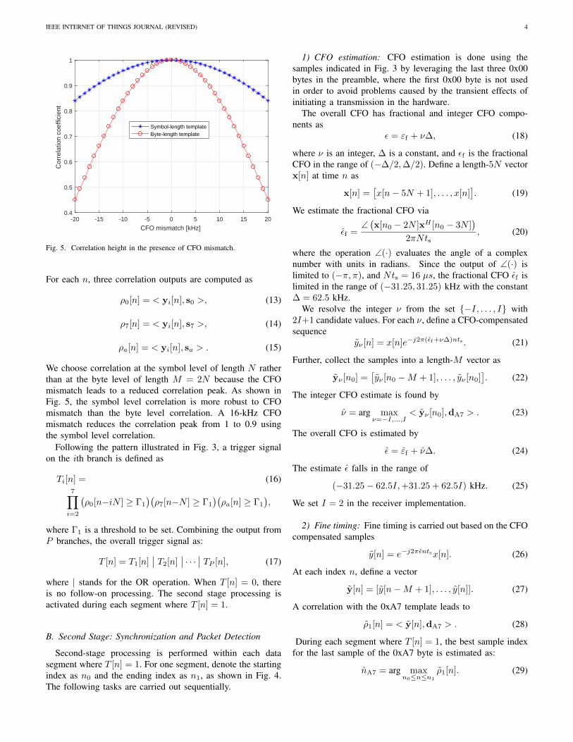
Fig. 5. Correlation height in the presence of CFO mismatch.
For each n, three correlation outputs are computed as
ρ0[n] = < yi[n], s0 >, (13)
ρ7[n] = < yi[n], s7 >, (14)
ρa[n] = < yi[n], sa > . (15)
We choose correlation at the symbol level of length N ratherthan at the byte level of length M = 2N because the CFOmismatch leads to a reduced correlation peak. As shown inFig. 5, the symbol level correlation is more robust to CFOmismatch than the byte level correlation. A 16-kHz CFOmismatch reduces the correlation peak from 1 to 0.9 usingthe symbol level correlation.
Following the pattern illustrated in Fig. 3, a trigger signalon the ith branch is defined as
Ti[n] = (16)7∏i=2
(ρ0[n−iN ] ≥ Γ1
)(ρ7[n−N ] ≥ Γ1
)(ρa[n] ≥ Γ1
),
where Γ1 is a threshold to be set. Combining the output fromP branches, the overall trigger signal as:
T [n] = T1[n]∣∣ T2[n]
∣∣ · · · ∣∣ TP [n], (17)
where | stands for the OR operation. When T [n] = 0, thereis no follow-on processing. The second stage processing isactivated during each segment where T [n] = 1.
B. Second Stage: Synchronization and Packet Detection
Second-stage processing is performed within each datasegment where T [n] = 1. For one segment, denote the startingindex as n0 and the ending index as n1, as shown in Fig. 4.The following tasks are carried out sequentially.
1) CFO estimation: CFO estimation is done using thesamples indicated in Fig. 3 by leveraging the last three 0x00bytes in the preamble, where the first 0x00 byte is not usedin order to avoid problems caused by the transient effects ofinitiating a transmission in the hardware.
The overall CFO has fractional and integer CFO compo-nents as
ε = εf + ν∆, (18)
where ν is an integer, ∆ is a constant, and εf is the fractionalCFO in the range of (−∆/2,∆/2). Define a length-5N vectorx[n] at time n as
x[n] =[x[n− 5N + 1], . . . , x[n]
]. (19)
We estimate the fractional CFO via
εf =∠(x[n0 − 2N ]xH [n0 − 3N ]
)2πNts
, (20)
where the operation ∠(·) evaluates the angle of a complexnumber with units in radians. Since the output of ∠(·) islimited to (−π, π), and Nts = 16 µs, the fractional CFO εf islimited in the range of (−31.25, 31.25) kHz with the constant∆ = 62.5 kHz.
We resolve the integer ν from the set {−I, . . . , I} with2I+1 candidate values. For each ν, define a CFO-compensatedsequence
yν [n] = x[n]e−j2π(εf+ν∆)nts . (21)
Further, collect the samples into a length-M vector as
yν [n0] =[yν [n0 −M + 1], . . . , yν [n0]
]. (22)
The integer CFO estimate is found by
ν = arg maxν=−I,...,I
< yν [n0],dA7 > . (23)
The overall CFO is estimated by
ε = εf + ν∆. (24)
The estimate ε falls in the range of
(−31.25− 62.5I,+31.25 + 62.5I) kHz. (25)
We set I = 2 in the receiver implementation.
2) Fine timing: Fine timing is carried out based on the CFOcompensated samples
y[n] = e−j2πεntsx[n]. (26)
At each index n, define a vector
y[n] = [y[n−M + 1], . . . , y[n]]. (27)
A correlation with the 0xA7 template leads to
ρ1[n] = < y[n],dA7 > . (28)
During each segment where T [n] = 1, the best sample indexfor the last sample of the 0xA7 byte is estimated as:
nA7 = arg maxn0≤n≤n1
ρ1[n]. (29)
IEEE INTERNET OF THINGS JOURNAL (REVISED) 5
3) Packet detection: To reduce the probability of falsealarms, we further verify that the bytes preceding 0xA7 areindeed 0x00. Define correlation outputs as
ρ0[n] = < y[n],d00 >, (30)
where y[n] is defined in (27). The packet detection variableis determined as:
D =(ρ1[nA7] ≥ Γ2
) 6∏i=2
(ρ0[nA7−iN ] ≥ Γ2
), (31)
where Γ2 is a pre-defined threshold.At each instance when D = 1, a packet arrival is declared,
and the third-stage processing is activated. The timing offsetnA7 and the CFO estimate ε are passed to the third stage.
4) Link Quality Indicator: Per detected packet, the receivedsignal strength indicator (RSSI) is the energy of the receivedsamples corresponding to the three 0x00 bytes as:
E =1
6N
nA7−2N∑n=nA7−8N+1
|x[n]|2. (32)
The link quality indicator (LQI) can be evaluated by anestimate on the signal to noise ratio (SNR) as follows. Define
ζ = < x[nA7 − 3N ],x[nA7 − 2N ] >, (33)
where x[n] is defined in (19). The expected value of thecorrelation is ζ = SNR/(1 + SNR), and hence the SNR canbe estimated as:
SNR =ζ
1− ζ. (34)
C. Third Stage: Data Detection
With the correct timing and the estimated CFO, we obtainthe compensated data sequence as
r[n] = e−j2πεntsx[n+ nA7], n = 1, 2, ... (35)
We adopt a length-K linear equalizer for channel equalizationas detailed in [30]. Corresponding to the lth symbol to bedetected, the equalizer coefficients are collected into a vectorof K = K1 +K2 + 1 taps as
f [l] =[f [l;−K1], ..., f [l; 0], ...f [l;K2]
]. (36)
We will rely on decision-directed equalization. Let f [l− 1] bethe equalizer computed based on the (l − 1)-th symbol. Forthe l-th symbol, the equalizer output is:
z[l] = f [l−1]R[l], (37)
wherez[l] = [z[lN −N + 1], · · · , z[lN ]], (38)
R[l] =
r[lN −N + 1−K1] . . . r[lN −K1]
......
r[lN −N + 1] . . . r[lN ]...
...r[lN −N + 1 +K2] . . . r[lN +K2]
. (39)
The equalized sequence is used to detect the symbol throughthe maximum-correlation criterion as:
s[l] = arg maxs
Re{z[l]sH}, (40)
where s is the data sequence corresponding to the 16 possiblechip sequences in Table I.
Assuming that the decoded symbol s[l] is correct, theequalizer at the lth symbol is updated as:
f [l] = s[l]RH [l]([R[l]RH [l])−1. (41)
For initialization, f [0] is computed based on the 0xA7 bytein the preamble. The equalizer update and the data detectionorder is:
f [0]→ s[1]→ f [1]→ s[2]→ · · · (42)
Typically, the decision directed approach is susceptible toerror propagation where one incorrect decision will impact thedetection of later symbols. However, a single symbol errormeans that the whole packet is in error, and hence the errorpropagation does not negatively affect the packet deliveryratio.
A basic symbol-by-symbol update is presented here forconvenience. Alternatively, one can update the equalizer everyseveral symbols. For noise suppression, one can update theequalizer by stacking several symbols together. One conve-nient variation is to update the equalizer byte-by-byte, whereeach byte contains two symbols.
IV. GNU RADIO IMPLEMENTATION
The GNU Radio IEEE 802.15.4 testbed in [20], [21] im-plements the communication stack from the physical layer upto the network layer, and allows the application layer to beattached easily. This implementation is included in the GNURadio 3.8 release and is popular in the GNU Radio community.This paper only focuses on the receiver portion of the OQPSKphysical layer, and aims to improve the error performance.
A. Enhancing the MSK-based receiver [19]–[21]
Fig. 6 shows the flowgraph of the MSK-based receiver[20], [21] in gnuradio-companion (GRC). There are four keymodules.
• The Quadrature Demod module takes the phase dif-ference of consecutive samples ∠(x∗[n−1]x[n]), which isan estimate of the instantaneous frequency of the receivedsignal.
• The Single Pole IIR Filter module tracks theDC bias from the frequency estimates due to the carrierfrequency shift. The DC bias is subtracted from thefrequency estimates.
• The Clock Recovery MM module implements theMuller and Mueller timing recovery algorithm [31] andoutputs a recovered chip sequence.
• The custom-made Packet Sink module performsframe synchronization and data detection, and outputs thedecoded packet.
We recommend to add two modules to improve the perfor-mance of the MSK-based receiver.

IEEE INTERNET OF THINGS JOURNAL (REVISED) 6
Fig. 6. The current MSK-based receiver in [21].
Fig. 7. The proposed enhancement for the MSK-based receiver.
Fig. 8. The flowgraph of the proposed coherent OQPSK receiver.
• The Decimating FIR Filter module implementsa matched filtering (MF) operation on the raw frequencyestimates, with two filter taps (1/2, 1/2).
• The Low Pass Filter (LPF) module aims to reducethe noise as much as possible before taking the phasedifference of the incoming samples. The sampling ratefor the GNU Radio implementation is 4 MHz, with theUSRP baseband bandwidth set at 2 MHz. As the null-to-null frequency band of the incoming signal is (−1.5, 1.5)MHz [9], we set the cutoff frequency at 1.5 MHz with atransition band of 0.1 MHz.
As we shall see in Section V-A, the MF module will bringabout 4 to 5 dB performance gain while the LPF module willbring additional 1 dB performance improvement.
B. The Proposed Coherent receiver
The coherent receiver described in Section III has beenimplemented in the GNU Radio framework and its flowgraphis shown in Fig. 8. The code for the blocks can be foundin the GitHub repository at [32]. There are six custom-mademodules.
• The Divider module outputs the incoming complexdata samples x[n] and the squared magnitudes |x[n]|2.
• The Power Step module computes the power sum∑Ni=1 |x[n − i]|2, which is needed by all correlation
operations in other modules.• The Pre_CFO_Fix module outputs a complex sequence
after a pre-fixed CFO compensation. To speed up theprocessing, the pre-CFO value is chosen so that it dividesthe sampling rate fs, i.e., εi = fs/Q for an integer Q.This way, ej2πεints = ej2πn/Q repeats itself after Qsamples and a finite-size look-up table can be used to

IEEE INTERNET OF THINGS JOURNAL (REVISED) 7
store the values. Also, the pre-CFO values εi and −εiare paired so that e−j2πεits are directly obtained fromej2πεits by conjugation.
• The Trigger module implements the triggering oper-ation described in Section III-A and outputs Ti[n] in(16). For the correlation operations, we downsample thecorrelation template and the received samples by two. Thedownsampled templates d0,d7,da have values of only±1,±i, so no actual multiplication needs to be carriedout when evaluating the inner products involved.
• The Synchronization module implements the syn-chronization and packet detection operation described inSection III-B, and outputs the timing and CFO estimates(nA7, ε). The received samples are downsampled by twofor the correlation operation in (28) and downsampled by4 for the CFO estimation in (20).
• The Decode module implements the data detection mod-ule in Section III-C and outputs the decoded data packet.We have chosen the byte-by-byte update for the datademodulation. With simulations, we confirmed that theperformance of the symbol-by-symbol update is nearlythe same as the byte-by-byte update.
The parameters that can be customized by the users include:(a) the number of correlation branches; (b) the CFO valueson the branches; (c) the detection threshold Γ1 in the triggermodule; and (d) the detection threshold Γ2 in the synchroniza-tion module. Four correlation branches are used in Fig. 8 andhence two Pre_CFO_Fix and four Trigger modules areshown.
C. Computational Requirements
The computational requirements of different modules of theproposed receiver are analyzed below.
• The Power Step module requires two real multipli-cations and N real additions per incoming data sam-ple. The Pre_CFO_fix module requires two complexmultiplications per sample. The Trigger module hasno complex multiplications in the correlators as thedownsampled templates have only ±1 values, but hasN/2 complex additions and two real divisions. WithP = 4 branches, the first stage of the receiver involves 4complex multiplications, 2 real multiplications, 2P = 8real divisions, and PN/2 = 128 complex additions perincoming data sample.
• The Synchronization module is run once per de-tected packet. CFO compensation in (26) over 5 bytesin the preamble requires 5N = 320 complex multipli-cations. Fine timing in (29) is typically accomplishedwithin four samples. The operations in (29) and (30) haveno more than 4 + 5 = 9 byte-level correlations, whichamounts to 2 × 9N/2 = 576 complex additions but nocomplex multiplications. The synchronization complexityis small relative to other modules as it occurs only onceper data packet.
• The Decode module is run on the detected packet. Letus only track the number of complex multiplications here.The matrix inversion in (41) has complexity on the order
of O(K3), and is counted to have 255 complex multipli-cations in our current implementation. For each updatein the byte-by-byte receiver, the numbers of complexmultiplications corresponding to (35), (37), (40), (41)are 2N , 2KN , 2 · 16 · N , 2NK2 + 255 + 2NK + K2,respectively. With N = 64 and K = 4, there are a totalof 5519 complex multiplications per byte update, whichcorrespond to 43 complex multiplications per incomingdata sample.
The MSK-based receiver has much lower complexity. TheQuadrature Demod module has one complex multiplica-tion per sample. The Clock Recovery MM runs on realsamples and has 8 real multiplications per sample using thedefault 8-tap Minimum Mean Squared Error (MMSE) inter-polator. The Clock Recovery MM outputs chip sequencesat half the sampling rate. In the Packet Sink module,frame synchronization with 0xA7 uses 64 bit-level additionsper chip. Once 0xA7 is found, the despreading operation runs16 correlators with each correlator having 32 chips. To decodeone byte of data, a total of 2 ·16 ·32 = 1024 bit-level additionsare needed, corresponding to 1024/128 = 8 bit-level additionsper incoming data sample.
To obtain an intuitive understanding, we put three receiversin one flowgraph and feed them with consecutive 30-bytedata packets with 1 ms inter-packet separation. We accessthe Performance Counters, in particular the averageclock cycles in call to the modules, through the use ofControlPort in the GNU Radio [33]. Based on the mea-surements, we infer that the enhanced MSK-based receiverrequires approximately 2.7 times clock cycles relative to theoriginal MSK-based receiver, which reduces to 1.4 times if theLPF is dropped (alternatively, the generic LPF module couldbe replaced by a custom-made module for speedup). On theother hand, the proposed receiver requires approximately 31times clock cycles than the original MSK-based receiver. Notethat the proposed receiver has not yet been optimized anda careful optimization could lead to multi-fold speedup. Forexample, the implementation of an IEEE 802.11 transceiver in[34] has been accelerated in [35] by a factor between 2× and10× depending on the modulation and code scheme used.
V. SIMULATED PERFORMANCE
We set the following parameters for the proposed receiveruploaded in [32]. There are a total of P = 4 branches with pre-fixed CFO values ± fs
250 = ±16 kHz,± fs83 = ±48.2 kHz. The
detection thresholds are set as Γ2 = 0.3 and Γ1 = 0.8Γ2 =0.24. In Section V-A, we use the packet delivery ratio (PDR)as the performance metric to compare the coherent receiverand the MSK-based receivers. Other performance metrics areused to evaluate the coherent receiver in Section V-B.
A. PDR Performance of Different Receivers
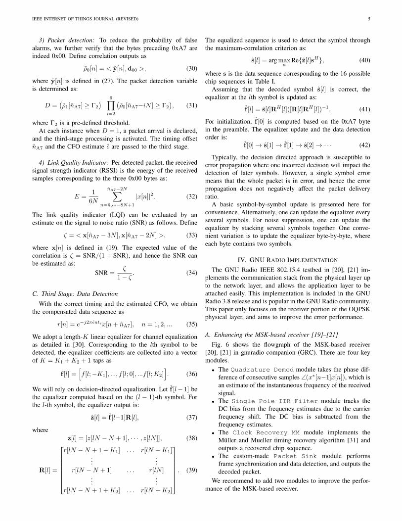
Figs. 9 and 10 show the receiver performance for packets of30 and 120 bytes in the presence of additive white Gaussiannoise (AWGN), where the CFO value is uniformly drawnfrom the interval [−64, 64] kHz. For each SNR point, severalthousand packets are used for performance evaluation. The
IEEE INTERNET OF THINGS JOURNAL (REVISED) 8
-10 -8 -6 -4 -2 0 2 4 6 8 10
Input SNR [dB]
0
0.1
0.2
0.3
0.4
0.5
0.6
0.7
0.8
0.9
1P
DR
Proposed, w/ LPFProposed, w/o LPFMSK, w/ LPF & MFMSK, w/ MFCurrent MSK receiver
Fig. 9. PDR performance in AWGN, packet length: 30 bytes.
-10 -8 -6 -4 -2 0 2 4 6 8 10
Input SNR [dB]
0
0.1
0.2
0.3
0.4
0.5
0.6
0.7
0.8
0.9
1
PD
R
Proposed, w/ LPFProposed, w/o LPFMSK, w/ LPF & MFMSK, w/ MFCurrent MSK receiver
Fig. 10. PDR performance in AWGN, packet length: 120 bytes.
PDR curve of the original MSK-based receiver is consistentwith that in Fig. 9 of [23], where an input SNR of 5 dB yieldsa PDR of 0.5 for packets with 20 bytes. We have made thefollowing observations:
• For the modified MSK-based receiver, the MF moduleintroduces 4 to 5 dB power gain and the LPF moduleintroduces another 1 dB Gain.
• The coherent receiver with or without the LPF modulehas similar performance. Hence, the LPF module isbypassed in the GNU Radio package for the coherentreceiver.
For convenience, we collect the PDR curves of the proposedreceiver without LPF, the enhanced MSK receiver with bothLPF and MF, and the original MSK receiver in Fig. 11, forpackets of 30 and 120 bytes. We observe that the enhancedMSK receiver has about 5 dB gain over the original MSKreceiver, while its performance lags behind the proposed
-10 -8 -6 -4 -2 0 2 4 6 8 10
Input SNR [dB]
0
0.1
0.2
0.3
0.4
0.5
0.6
0.7
0.8
0.9
1
PD
R
ProposedEnhanced MSKCurrent MSK
dashed lines: 30 bytessolid lines: 120 bytes
5.8 dB
6.0 dB
5.5 dB
4.9 dB
Fig. 11. PDR performance in AWGN.
-10 -8 -6 -4 -2 0 2 4 6 8 10
Input SNR [dB]
0
0.1
0.2
0.3
0.4
0.5
0.6
0.7
0.8
0.9
1
PD
R
about 1.5 dB
about 2.7 dB
true timing provided
true timing, CFO, and equalizer provided
Fig. 12. Comparison with two genie-aided receivers, packet length: 120 bytes.
coherent receiver by about 6 dB.The performance gain of the proposed coherent receiver
over the MSK receiver in [21] is larger than we expected atthe beginning of this work. It is well-known that antipodalsignalling (e.g., binary phase shift keying) outperforms binaryorthogonal signalling (e.g., binary frequency shift keying) by3 dB and coherent decoding of binary orthogonal signalsoutperforms noncoherent decoding by about 1 dB. Hence, westarted the work expecting a 4 dB improvement resulting fromcoherent decoding of OQPSK over non-coherent decodingof MSK. However, there is a large spreading gain in theIEEE 802.15.4 OQPSK physical layer. The proposed coherentreceiver first establishes carrier and time synchronization, andthe demodulator works well even when the input SNR iswell below 0 dB due to the large spreading gain. On theother hand, the key step in the MSK-based receiver is totake the phase difference of consecutive received samplesx[n], which enables subsequent low-complexity symbol syn-

IEEE INTERNET OF THINGS JOURNAL (REVISED) 9
0.2 0.22 0.24 0.26 0.28 0.3 0.32 0.34 0.36
Threshold 2
0
2
4
6
8
10
12
14
16
18
20N
umbe
r of
Fal
se A
larm
s
SNR: -9, -7, ..., 7, 9 dB
Fig. 13. Number of false alarms for data segments of 1 ms long.
chronization and data detection. Let x[n] = s[n] + w[n],where s[n] is the signal and w[n] is the noise. The operation∠((s[n−1] + w[n−1])∗(s[n] + w[n])
)works well only when
the signal is reasonably stronger than the noise, otherwise thephase estimate will correspond to the noise rather than thesignal. This step operates on a per-sample basis, so it doesnot benefit from the redundancy in the modulation, and henceis one key performance bottleneck for the MSK based receiver.
In Fig. 12, we compare the proposed receiver with twogenie-aided receivers for packets of length 120 bytes. Inboth genie-aided receivers, all packets are correctly detected.The first receiver assumes perfect timing nA7 = nA7 butwith practical CFO estimation and data-directed equalizerupdate, while the second receiver assumes perfect timingnA7 = nA7, perfect CFO estimation ε = ε and the optimalequalizer f [l] = [0, 1, 0, 0] for an AWGN channel. The secondreceiver corresponds to the receiver analyzed in [9], whichassumes perfect carrier and time synchronization and testsonly the demodulation performance in an AWGN channel.Since every four bits are mapped into 64 samples, Eb/N0 is10 log10(64/4) = 12 dB higher than the input SNR. Fig. 4 of[9] shows that a symbol error rate (SER) of 10−4 is achievedat Eb/N0 = 7 dB and hence SNR = −5 dB, and thecorresponding PDR is (1 − SER)120·2 = 0.98 for a 120-bytepacket. Our result in Fig. 12 is hence consistent with the unionbound and the simulated performance in Fig. 6 of [9].
From Fig. 12, we observe that the proposed receiver is about2.7 dB away from the ideal receiver with perfect carrier andtime synchronization in an AWGN channel [9]. Out of the2.7 dB gap, 1.5 dB is attributed to the CFO estimation anddata detection modules and 1.2 dB is attributed to the packetdetection and time synchronization modules.
B. Detection Threshold, CFO and SNR Estimation
Here we report other performance metrics for the proposedcoherent receiver: packet detection performance, CFO estima-tion accuracy and SNR estimation.
-10 -8 -6 -4 -2 0 2 4 6 8 10
Input SNR [dB]
0
2
4
6
8
10
12
14
CF
O R
MS
E [k
Hz]
FullDownsampled
Fig. 14. Accuracy of the CFO estimation.
-10 -8 -6 -4 -2 0 2 4 6 8 10
Input SNR [dB]
-10
-5
0
5
10E
stim
ated
SN
R [d
B]
EstimatedTrue SNR
Fig. 15. The estimated SNR as a link quality indicator.
Packet detection has two probabilities to deal with: Prob-ability of detection and probability of false alarms. Lowerdetection thresholds can improve the probability of detectionbut will increase the probability of false alarms. We choosethe constant as
Γ1 = 0.8 Γ2 (43)
and vary Γ2 between 0.2 and 0.4. It turns out that the falsealarms due to additive white Gaussian noise can be neglectedin view of the randomly generated data packets. Fig. 13depicts the joint effect of mixing randomly generated packets(without the preamble portion) with additive noise on thenumber of false alarms processing each data segment of 1ms (corresponding to a packet of 30 bytes). When Γ2 = 0.3and Γ1 = 0.8Γ2 = 0.24, false alarms are negligible. We hencerecommend these threshold values for the coherent receiver.
For the correctly detected packets, the root mean-squarederror (RMSE) of the CFO estimates is shown in Fig. 14,
IEEE INTERNET OF THINGS JOURNAL (REVISED) 10
0
0.5
1
1.5
2
2.5
3
3.5A
mpl
itude
10-3
0 2 4 6 8 10 12 14 16
sample index
0
0.5
1
1.5
2
2.5
3
3.5
4
Am
plitu
de
10-3
0 2 4 6 8 10 12 14 16
sample index
Fig. 16. Example channel impulse responses: Sample interval ts = 0.25 µs.
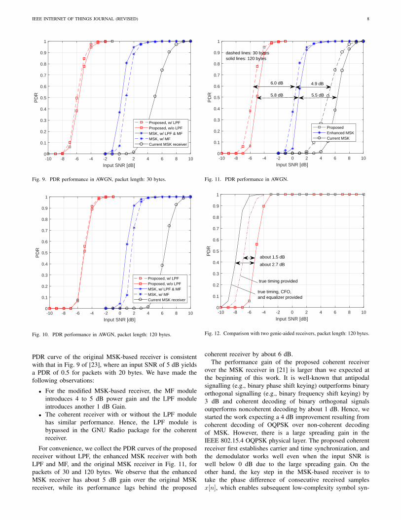
where the original data sequence could be also downsampledby four times to speed up the processing. As the input SNRstays above −6 dB, the RMSE is below 4 kHz. The averagevalues of the SNR estimates are depicted in Fig. 15 with thestandard deviation illustrated via error bars around the mean.The average SNR agrees with the true SNR very well. Thestandard deviation of the SNR estimates is about 1.5 dB atinput SNR of −5 dB and is about 0.75 dB at input SNR of 0dB. The SNR estimate can serve as one reliable link qualityindicator, especially when averaged over several packets.
C. Emulated Performance based on Recorded Data SetsWe used USRP to record several data sets from the trans-
missions of a TI CC2650 device. The estimated CFO betweenthe transmitter and the receiver is about 10.5 kHz. Channelestimates based on the least-squares fitting of the receivedsamples corresponding to the 0xA7 byte are plotted in Fig. 16,and are similar to those reported in [36]. These channel plotsmotivated the choice of the four-tap equalizer with K1 = 1and K2 = 2.
Fig. 17. The TI CC2650 transmitter on a moving cart.
Fig. 18. Five receivers placed side by side: three GNU Radio receivers andtwo TI CC2652 receivers.
VI. FIELD TEST
We performed a field test in an indoor environment. Fig. 17shows a TI CC2650 transmitter [37], placed on a cart.Fig. 18 shows the receiver setup with five receivers placedtogether. One monopole antenna is connected to a dividerwhich provides identical RF signals to three USRP unitsthrough wired connections. With samples from USRP devices,three GNU Radio receivers were running: a) the proposedcoherent receiver, b) the enhanced MSK-based receiver andc) the original MSK-based receiver. Two CC2652 receiversfrom Texas Instruments [38] were placed near the monopoleantenna, one on the left and one on the right. The CC2652receivers have their own printed-circuit board (PCB) inverted-F antennas, whose beam patterns can be found in [39]. Thenormalized receiver gains on the USRP units were set to 0.9.To avoid interference from the WiFi, we used IEEE 802.15.4channel 20 centered at 2.450 GHz.
The third floor of the Information Technology and Engi-neering (ITE) building at the UConn campus, whose floormap is shown in Fig. 19, was used for tests. At points P1,P2, P3, the transmitter cycled the power levels from the set often values {−21,−18,−15, . . . , 0, 3, 5} dBm, where 5 dBmis the maximum power allowed by the device. Point P1 is28 meters away and has a direct line-of-sight (LOS) path tothe receiver. P2 and P3 are 40 and 49 meters away fromthe receiver, respectively. Although there are open hallwaysbetween P2/P3 and the receiver, the transmission paths mightnot be claimed as LOS paths. All receivers decoded nearly allthe packets at P1 for all power levels. Figs. 20 and 21 showthe PDR performance at P2 and P3, respectively. For eachPDR evaluation, 500 packets were sent with packet length 30bytes. From Figs. 20 and 21, we observe that the proposed

IEEE INTERNET OF THINGS JOURNAL (REVISED) 11
Fig. 19. The floor plan with marked receiver and transmitter locations.
receiver has approximately a 6 dB gain over the enhancedMSK-based and a 10 dB gain over the original MSK-basedreceiver. These performance gains are mostly consistent withthe simulation results. The TI receivers are worse than theMSK-based receiver and show large performance variationsbetween P2 and P3. However, the TI receivers and the USRPreceivers do not share the same antennas and the antennapatterns have an influence that cannot be quantified here. Inaddition, we tried to transmit packets at point P4, which ison the other side of the hallway and has transmission pathsblocked from the receiver. At a transmit power of 5 dBm, theproposed coherent receiver received 80% of the packets whileall other receivers received zero packets.
We further examine the SNR estimates provided by thecoherent receiver (the “debug” option in the Decode modulein Fig. 8 needs to be turned on). The average SNRs at P1-P4are reported in Fig. 22 as a function of transmit power, andthe standard deviation is about 1.6 dB. Moving the transmitterfrom P1 to P2, nearly 10 dB SNR is lost, while P2 and P3 havealmost the same SNRs. Corresponding to the transmit powerof 5 dBm, the average SNR is only −2.7 dB at P4, whileabout 17 dB at P3. The SNR estimates shed light on the PDRperformance differences in Fig. 20 and 21. We underscorethat indoor propagation channels are complex and the receiverperformance is not merely a function of the transmissiondistance.
VII. CONCLUSION
In this paper, we presented a coherent receiver for the IEEE802.15.4 OQPSK physical layer and implemented it in theGNU Radio framework. The receiver achieves a significantimprovement around 11 dB in performance over an existingGNU radio receiver, and maintains about 6 dB gain whenthe latter is suitably improved. This proposed receiver issuitable for SDR-based high-performance gateways in IoTapplications. Our future work will include code optimizationfor processing speeds and application of the proposed receiverin IoT testbeds.
AUTHORS’ CONTRIBUTIONS
E. Faulkner and Z. Yun have contributed equally to thiswork. E. Faulkner focused on algorithm development and
-20 -15 -10 -5 0 5
transmit power [dBm]
0
10
20
30
40
50
60
70
80
90
100
PD
R
ProposedEnhanced MSKCurrent MSKTI Sensor 1TI Sensor 2
5.9 dBm 4.2 dBm
Fig. 20. PDR vs transmission power at P2.
-20 -15 -10 -5 0 5
transmit power [dBm]
0
10
20
30
40
50
60
70
80
90
100
PD
R
ProposedEnhanced MSKCurrent MSKTI Sensor 1TI Sensor 2
5.9 dBm 3.4 dBm
Fig. 21. PDR vs transmission power at P3.
performance analysis, while Z. Yun implemented the GNUradio receiver and led the experimental validation.
ACKNOWLEDGEMENT
The work by Z. Yun and S. Han is partially supported bythe National Science Foundation under NSF Awards CNS-1925706 and IIP-1919229. We thank Ms. Natong Lin forher help in assisting the experimental tests, and Kaiyuan Liufor his help in investigating the receiver complexity. We aregrateful to Dr. Bloessl whose open-source GNU-radio receiverin [21] has motivated this work.
REFERENCES
[1] IEEE Standard for Low-Rate Wireless Networks, IEEE Std 802.15.4-2015 (Revision of IEEE Std 802.15.4-2011) Std., 2016.
[2] A. G. Ramonet and T. Noguchi, “IEEE 802.15.4 historical evolutionand trends,” in Prof. of 21st International Conference on AdvancedCommunication Technology (ICACT), 2019, pp. 351–359.

IEEE INTERNET OF THINGS JOURNAL (REVISED) 12
-20 -15 -10 -5 0 5
transmit power [dBm]
-10
-5
0
5
10
15
20
25
30E
stim
ated
SN
R [d
B]
Point 1
Point 2
Point 3
Point 4
Fig. 22. The estimated SNRs at P1, P2, P3, P4.
[3] L. Davoli, L. Belli, A. Cilfone, and G. Ferrari, “From Micro to MacroIoT: Challenges and solutions in the integration of IEEE 802.15.4/802.11and Sub-GHz technologies,” IEEE Internet of Things Journal, vol. 5,no. 2, pp. 784–793, 2018.
[4] N. Choudhury, R. Matam, M. Mukherjee, and L. Shu, “Beacon syn-chronization and duty-cycling in IEEE 802.15.4 cluster-tree networks:A review,” IEEE Internet of Things Journal, vol. 5, no. 3, pp. 1765–1788, 2018.
[5] W. Li, X. Hu, and T. Jiang, “Path loss models for IEEE 802.15.4 vehicle-to-infrastructure communications in rural areas,” IEEE Internet of ThingsJournal, vol. 5, no. 5, pp. 3865–3875, 2018.
[6] M. Wu, X. Hu, R. Zhang, and L. Yang, “Collision recognition inmultihop IEEE 802.15.4-compliant wireless sensor networks,” IEEEInternet of Things Journal, vol. 6, no. 5, pp. 8542–8552, 2019.
[7] G. Chen, X. Cao, L. Liu, C. Sun, and Y. Cheng, “Joint schedulingand channel allocation for end-to-end delay minimization in industrialWirelessHART networks,” IEEE Internet of Things Journal, vol. 6, no. 2,pp. 2829–2842, 2019.
[8] J. G. Proakis, Digital Communications. McGraw-Hill,4th edition, 2001.[9] P. Gupta and S. G. Wilson, “IEEE 802.15.4 PHY analysis: Power spec-
trum and error performance,” in Prof. of Annual IEEE India Conference,vol. 1, 2008, pp. 171–176.
[10] D. Park, C. S. Park, and K. Lee, “Simple design of detector in thepresence of frequency offset for IEEE 802.15.4 LR-WPANs,” IEEETransactions on Circuits and Systems II: Express Briefs, vol. 56, no. 4,pp. 330–334, 2009.
[11] S. Dai, H. Qian, K. Kang, and W. Xiang, “A robust demodulatorfor OQPSK-DSSS system,” Circuits, Systems, and Signal Processing,vol. 34, pp. 231–247, 01 2014.
[12] U. Pesovic, S. Durasevic, and P. Planinsis, “Carrier synchronization al-gorithm for software defined radio,” in Proc. of 25th TelecommunicationForum (TELFOR), 2017, pp. 1–4.
[13] K. Gorantla and V. V. Mani, “Synchronization in IEEE 802.15.4 Zigbeetransceiver using Matlab Simulink,” in Proc. International Conferenceon Advances in Computing, Communications and Informatics (ICACCI),2015, pp. 144–148.
[14] S. Yin, J. Cui, A. Luo, L. Liu, and S. Wei, “A highly efficient basebandtransceiver for IEEE 802.15.4 LR-WPAN systems,” in Prof. of 9th IEEEInternational Conference on ASIC, 2011, pp. 224–227.
[15] U. Pesovic, D. Gliech, P. Planinsic, Z. Stamenkovic, and S. Randic,“Implementation of coherent IEEE 802.15.4 receiver on software definedradio platform,” in Prof. of 23rd Telecommunications Forum Telfor(TELFOR), 2015, pp. 224–227.
[16] R. M. Koteng, “Evaluation of SDR-implementation of IEEE 802.15.4physical layer,” Master’s thesis, Norwegian University of Science andTechnology, 2006.
[17] A. Z. Mohammed, A. K. Nain, J. Bandaru, A. Kumar, D. S. Reddy,and R. Pachamuthu, “A residual phase noise compensation method forIEEE 802.15.4 compliant dual-mode receiver for diverse low power IoT
applications,” IEEE Internet of Things Journal, vol. 6, no. 2, pp. 3437–3447, 2019.
[18] N. Dehaese, S. Bourdel, H. Barthelemy, and G. Bas, “Simple demodula-tor for 802.15.4 low-cost receivers,” in Prof. of IEEE Radio and WirelessSymposium, 2006, pp. 315–318.
[19] T. Schmid, “GNU Radio 802.15.4 En- and Decoding,” University ofCalifornia Los Angeles, Tech. Rep., 2006.
[20] B. Bloessl, C. Leitner, F. Dressler, and C. Sommer, “A GNU Radio-based IEEE 802.15.4 Testbed,” in 12. GI/ITG KuVS FachgesprachDrahtlose Sensornetze (FGSN 2013), Cottbus, Germany, September2013, pp. 37–40.
[21] B. Bloessl, “Wirless Measurement and Experimentation (WIME),”https://www.wime-project.net/.
[22] R. Zitouni, L. George, and Y. Abouda, “A Dynamic Spectrum Accesson SDR for IEEE 802.15.4e networks,” in Proceedings of WirelessInnovation Forum, March 2015.
[23] B. Bloessl and F. Dressler, “msync: Physical layer frame synchronizationwithout preamble symbols,” IEEE Transactions on Mobile Computing,vol. 17, pp. 2321–2333, 2018.
[24] H. K. Benitez, C. H. Cabuso, M. T. De Leon, J. R. Hizon, and M. Ros-ales, “Implementation of a physical layer wireless sensor network testbedusing software defined radios,” in Prof. of International Symposium onMultimedia and Communication Technology (ISMAC), 2019, pp. 1–6.
[25] J. Gu, C. Chen, S. Zhu, and J. He, “Efficient Error Packet Recoverywithout Redundant Bytes for IEEE 802.15.4 Protocol,” in 3rd Interna-tional Symposium on Autonomous Systems (ISAS). Shanghai, China:IEEE, May 2019, pp. 418–423.
[26] S. Gvozdenovic, J. K. Becker, and D. Starobinski, “SDR-based PHYCharacterization of Zigbee Devices,” in 63rd International MidwestSymposium on Circuits and Systems (MWSCAS). Springfield, MA:IEEE, August 2020, pp. 129–132.
[27] S. Wang, Y. Li, C. Ming, and Z. Zhang, “Building Gateway Intercon-nected Heterogeneous ZigBee and WiFi Network Based on SoftwareDefined Radio,” in International Conference on Communications andNetworking in China (ChinaCom). Shanghai, China: Springer, Novem-ber 2019, pp. 445–456.
[28] C. Gavril, C.-Z. Kertesz, M. Alexandru, and V. Popescu, “SDR-basedGateway for IoT and M2M applications,” in Prof. of Baltic URSISymposium (URSI). Poznan, Poland: IEEE, May 2018, pp. 71–74.
[29] H. Hellstrom, M. Luvisotto, R. Jansson, and Z. Pang, “Software-definedwireless communication for industrial control: A realistic approach,”IEEE Industrial Electronics Magazine, vol. 13, no. 4, pp. 31–37, 2019.
[30] R. C. Johnson Jr, W. A. Sethares, and A. G. Klein, Software ReceiverDesign: Build Your Own Digital Communication System in Five EasySteps. Cambridge University Press, 1st edition, 2011.
[31] K. Mueller and M. Muller, “Timing recovery in digital synchronous datareceivers,” IEEE Transactions on Communications, vol. 24, no. 5, pp.516–531, 1976.
[32] https://github.com/cloud9477/gr-advoqpsk.[33] T. Rondeau, T. O’Shea, and N. Goergen, “Inspecting GNU Radio
Applications with ControlPort and Performance Counters,” in Proc.of 2nd ACM SIGCOMM Workshop of Software Radio ImplementationForum, Hong Kong, China, August 2013, pp. 65–70.
[34] B. Bloessl, M. Segata, C. Sommer, and F. Dressler, “An IEEE802.11a/g/p OFDM Receiver for GNU Radio,” in Proc. of 2nd ACMSIGCOMM Workshop of Software Radio Implementation Forum, HongKong, China, August 2013, pp. 9–16.
[35] G. Arcos, R. Ferreri, M. Richart, P. Ezzatti, and E. Grampın, “Acceler-ating an IEEE 802.11 a/g/p Transceiver in GNU Radio,” in Proc. of 9thLatin America Networking Conference (LANC’16), Valparaıso, Chile,October 2016, pp. 13–19.
[36] S. Ayvasik, M. Gursu, and W. Kellerer, “Veni Vidi Dixi: reliablewireless communication with depth images,” in Proceedings of the 15thInternational Conference on Emerging Networking Experiments AndTechnologies, Orlando, FL, USA, December 912, 2019.
[37] Texas Instruments, “SimpleLink 32-bit Arm Cortex-M3 multiprotocol2.4 GHz wireless MCU,” https://www.ti.com/product/CC2650.
[38] ——, “SimpleLink multi-standard CC26x2R wireless MCU LaunchPaddevelopment kit,” https://www.ti.com/tool/LAUNCHXL-CC26X2R1.
[39] ——, “Application Report: 2.4-GHz Inverted F Antenna,”https://www.ti.com/lit/an/swru120d/swru120d.pdf.