hb rgb light bar installation rev.1 022414€¦ · o sgs listed confirming to ul standard 2108 ......
TRANSCRIPT

!
TM
The HB Series Advantage!
o SGS listed confirming to UL Standard 2108 & 8750!o Certified to CSA Standard C22.2 No.9!o LED Life of 50K+ hours, under normal operating conditions!o Low wattage, low heat, low voltage (12DVC & 24VDC as indicated)!o Provide consistent and uniform illumination!o Emits no UV or infrared light and does not contain lead, mercury or glass!o Eco-friendly handling and disposal when required!o Available in RGB or customs options!o Available in Flood or Narrow beam angles in configuration lengths!o Set up for integrating using DMX, or other control protocol systems!o Suitable for wet locations, IP67!o Simple user friendly installation !o Top quality connectors and mounting hardware !o Zero warm-up time and no reduction to lamp life in normal operating conditions!
!
HIGH POWER RGB LED SERIES
For more informa-on, please visit ledpower.com or call 949.679.0031 Copyright 2013 LED Power Inc. All rights reserved
Architectural Illumination Systems!
TM
SPECIFICATIONS
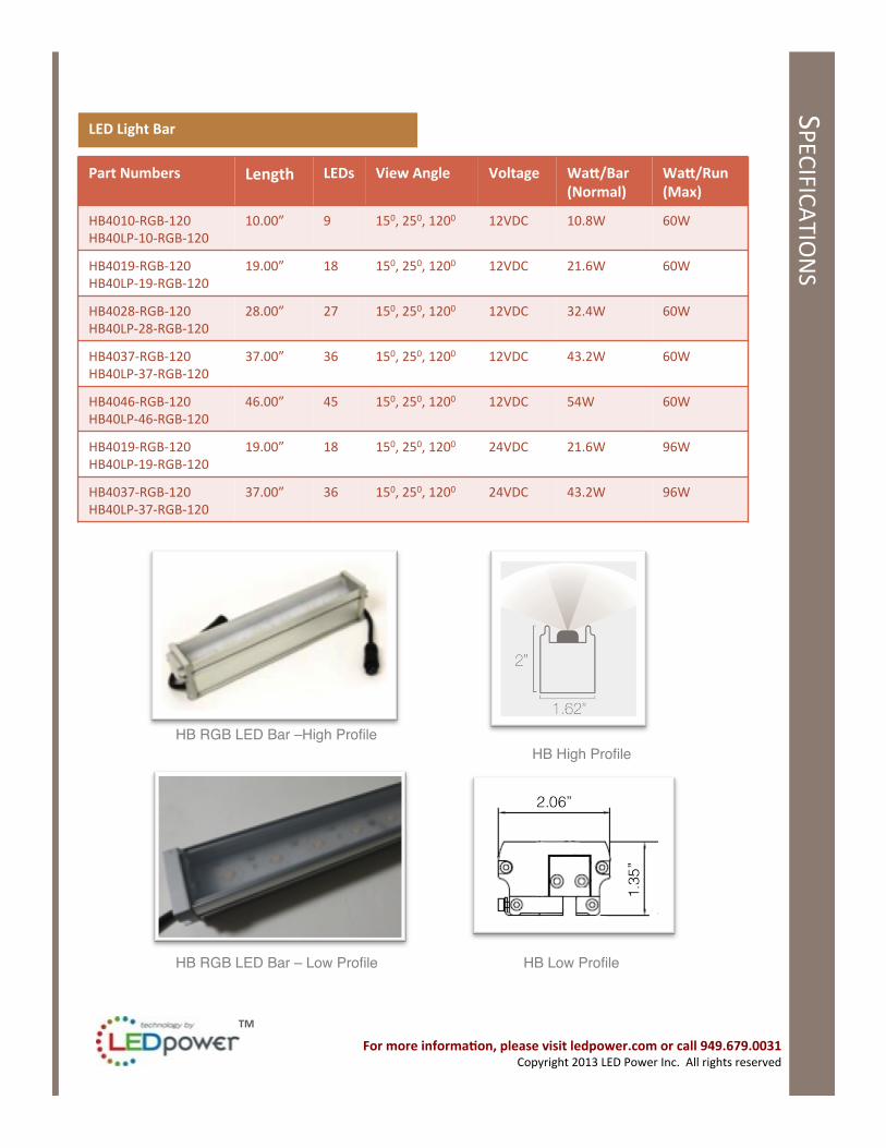
LED Light Bar
Part Numbers Length LEDs View Angle Voltage WaL/Bar (Normal)
WaL/Run (Max)
HB4010-‐RGB-‐120 HB40LP-‐10-‐RGB-‐120
10.00” 9 150, 250, 1200 12VDC 10.8W 60W
HB4019-‐RGB-‐120 HB40LP-‐19-‐RGB-‐120
19.00” 18 150, 250, 1200 12VDC 21.6W 60W
HB4028-‐RGB-‐120 HB40LP-‐28-‐RGB-‐120
28.00” 27 150, 250, 1200 12VDC 32.4W 60W
HB4037-‐RGB-‐120 HB40LP-‐37-‐RGB-‐120
37.00” 36 150, 250, 1200 12VDC 43.2W 60W
HB4046-‐RGB-‐120 HB40LP-‐46-‐RGB-‐120
46.00” 45 150, 250, 1200 12VDC 54W 60W
HB4019-‐RGB-‐120 HB40LP-‐19-‐RGB-‐120
19.00” 18 150, 250, 1200 24VDC 21.6W 96W
HB4037-‐RGB-‐120 HB40LP-‐37-‐RGB-‐120
37.00” 36 150, 250, 1200 24VDC 43.2W 96W
HB RGB LED Bar –High Profile!
For more informa-on, please visit ledpower.com or call 949.679.0031 Copyright 2013 LED Power Inc. All rights reserved
HB RGB LED Bar – Low Profile!
HB High Profile!
HB Low Profile!

TM
Accessories
Part Numbers
Descrip-on
HB40 Flat Bracket Flat Bracket
HB Cap Male End Cap
HB40 AdjBracket Adjustable Bracket
HB40 LTW24”M&F-‐4 M/F 4 pin 24” Jumper Wire Cable
HB40 LTW48”M&F-‐4 M/F 4 pin 48” Jumper Wire Cable
HB40 LTW12”FE-‐4P 12” 4 pin Female Starter Feed
Adjustable Bracket!
4 Pin Female Starter Feed Wire Cable!
M/F 4 Pin Jumper Wire Cable!
Flat Bracket! End Cap!
* Other Jumper and Starter Feed wire sizes available Contact LED Power for op_on and pricing
For more informa-on, please visit ledpower.com or call 949.679.0031 Copyright 2013 LED Power Inc. All rights reserved
LED Light Bar – Interface Controller
Part Numbers Descrip-on Dimension Input Voltage
Output Power
Output Current
AC-‐MP MINI Preprogrammed Mini Controller
7”x1.75”x1.5” 12V DC/24 V DC 36W 3Amp
DCI-‐DMX DMX Addressable Interface
7”x1.75”x1.5” 12V DC/24 V DC 60W @ 12V DC 96W @ 24V DC
6Amp
AU03-‐F/AU03-‐DMX Slave Controller/DMX Addressable Controller
7.5”x5”x2” 12V DC/24 V DC 60W @ 12V DC 96W @ 24V DC
6Amp
AC05 Preprogrammed Controller with 12 Shows
7.5”x5”x2”
12V DC/24 V DC 60W @ 12V DC 96W @ 24V DC
6Amp
SPECIFICATIONS
AC-MP MINI Interface Controller!DCI-DMX!

TM
SPECIFICATIONS
LED Light Bar – Power Supply
Part Numbers Descrip-on Dimension Input Voltage
Output Power
Output Current
PS-‐Dimmable-‐16192 60W MAGNETIC Power Supply
7”x3”x4” 120/240 /277
60W@12V DC 60W@24V DC
5Amp @ 12V DC 2.5 Amp @ 24V DC
PS-‐LED120A-‐0012V-‐50F 60W Electronic Power Supply
9.5”x1.5”x 1.2”
120 60W@12V DC 5Amp @ 12V DC
PS-‐LEDINTA0024V41FO 100W ELECTRONIC Power Supply
9.5”x1.5”x 1.2”
120/240 /277
96W@24V DC 4.1 Amp
PS-‐LED1003R15X3 (Op_onal)
NEMA Enclosure (Op_onal)
13.4”x2.75” x2.32”
-‐ -‐ -‐
100W Electronic Power Supply!
For more informa-on, please visit ledpower.com or call 949.679.0031 Copyright 2013 LED Power Inc. All rights reserved
NEMA Enclosure! 60W Magnetic Power Supply!
PREPARE ELECTRICAL WIRING!Electrical Requirements!• This RGB Color Changing lighting system is supplied with an appropriate power supply driver unit; this appliance unit must be supplied with 120V, 60Hz. and connected to an individual properly grounded branch circuit, protected by a 15 or 20. Amp circuit breaker or time delay fuse. ! •The HB RGB LED Light Bar is a CLASS 2, 12 VDC or 24VDC as indicated, low voltage luminary and must be used with an appropriate power supply driver unit. Failure to connect this lighting system correctly will violate all warranty claims.!• Wiring must be 2 wires with ground and rated for 75°C (176°F).!NOTE: Consult local building codes and guidelines on selecting wires. Wires must be UL Listed.!!Grounding Instructions-Cable Direct!This lighting system must be connected to a grounded metal, permanent wiring system, or an equipment grounding conductor must be run with the circuit conductors and be connected to the equipment grounding terminal.!

TM
MOUNTING LIGHT FIXTURE
Mounting Light Fixture with Mounting Clips!• Mounting clips, whether flat or rotating adjustable type, must be mounted to a flat surface using appropriate screws or other fasteners.!• See the mounting clip diagrams!• Lock out and tag out the circuit breaker for the lighting circuit of the area where the LED light fixtures are being installed.!• Turn the light switch to “off” to ensure no power is active.!• Remove any hazards in order to access the electrical raceway or necessary space.!• Use a Voltmeter and check that there is no voltage.!• Remove any existing fixtures, wiring harnesses, etc.!• Remove any Ballast or other power supplies from the electrical raceway or necessary space.!• Wear gloves to prevent injury when handling the old materials such as reflectors, ballasts, etc.!
HB RGB!INSTALLATION!
FOR YOUR SAFETY!Read and observe all CAUTIONS and WARNINGS shown throughout these instructions. While performing installation described, gloves, safety glasses or goggles should be worn.!
For more informa-on, please visit ledpower.com or call 949.679.0031 Copyright 2013 LED Power Inc. All rights reserved
HP SERIESSolution Document
For more information, please visit 3-form.com or call 800.726.0126DECEMBER 2012 | MAN-034 HP LIGHTING | REV 003 © 2012 3form, Inc. All rights reserved. 3
600.04.01Transaction Lightbox, Corner Wrap
EXAMPLE 1
RTG
3-60-487 Power Supply
OVERALL VIEW
90’’
42’’
4’’
SECTION VIEW
HP SERIES LEDs
3/8’
’ VAR
IA
6’’
1"X2" ANGLEDALUMINUM
REFLECTIVE PANEL
LED Bar
3-60-381 Adjustable Bracket
3-60-479 Jumper Wire Cable*Required for > 6” span
*See page 6 for wiring diagram*An optional dimmer is also available - see dimming wiring diagram on page 7 - page 8
Flat Bracket! Adjustable Bracket!
TM
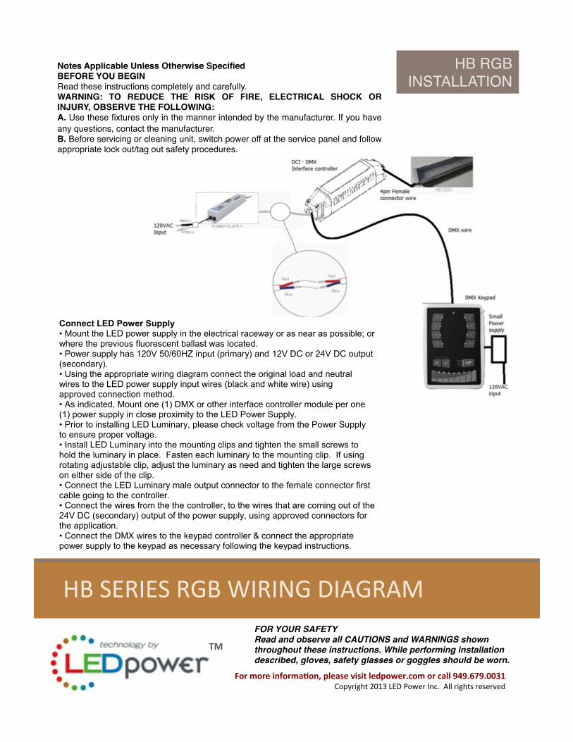
HB SERIES WIRING DIAGRAM
For more informa-on, please visit ledpower.com or call 949.679.0031 Copyright 2013 LED Power Inc. All rights reserved
HB SERIES RGB WIRING DIAGRAM
HB RGB!INSTALLATION!
Notes Applicable Unless Otherwise Specified!BEFORE YOU BEGIN!Read these instructions completely and carefully.!WARNING: TO REDUCE THE RISK OF FIRE, ELECTRICAL SHOCK OR INJURY, OBSERVE THE FOLLOWING:!A. Use these fixtures only in the manner intended by the manufacturer. If you have any questions, contact the manufacturer.!B. Before servicing or cleaning unit, switch power off at the service panel and follow appropriate lock out/tag out safety procedures.!
FOR YOUR SAFETY!Read and observe all CAUTIONS and WARNINGS shown throughout these instructions. While performing installation described, gloves, safety glasses or goggles should be worn.!
• Remove any existing fixtures, wiring harnesses, etc.• Remove any Ballast or other power supplies from the electrical raceway or necessary space.• Wear gloves to prevent injury when handling the old materials such as reflectors, ballasts, etc.
Connect LED Power Supply• Mount the LED power supply in the electrical raceway or as near as possible; orwhere the previous fluorescent ballast was located.• Power supply has 120V 50/60HZ input (primary) and 12V DC or 24V DC output (secondary).• Using the appropriate wiring diagram connect the original load and neutralwires to the LED power supply input wires (black and white wire) usingapproved connection method.• As indicated, Mount one (1) DMX or other interface controller module per one (1) power supply in close proximity to the LED Power Supply. • Prior to installing LED Luminary, please check voltage from the Power Supply to ensure proper voltage.• Install LED Luminary into the mounting clips and tighten the small screws to hold the luminary in place. Fasten each luminary to the mounting clip. If using rotating adjustable clip, adjust the luminary as need and tighten the large screws on either side of the clip. • Connect the LED Luminary male output connector to the female connector first cable going to the controller.• Connect the wires from the the controller, to the wires that are coming out of the24V DC (secondary) output of the power supply, using approved connectors for the application.• Connect the DMX wires to the keypad controller & connect the appropriate power supply to the keypad as necessary following the keypad instructions.
Note: LED Power, Inc. LED light fixtures are polarity sensitive. If the fixtures do not light up, the wires may need to be reversed. • Additional conductors may be needed to connect the power supply to theexisting wiring in the raceway or other section. Use conductors of proper size andrating as per local and national codes.• The LED power supply enclosure case includes a terminal for grounding the incoming 120V 50/60HZ ground wire. Attach LED power supply to a
TM
For more informa-on, please visit ledpower.com or call 949.679.0031 Copyright 2013 LED Power Inc. All rights reserved
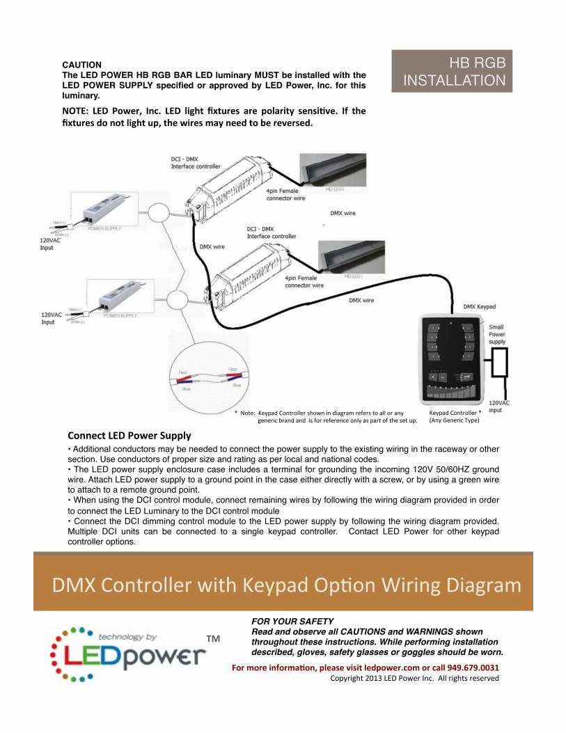
DMX Controller with Keypad Op_on Wiring Diagram
Connect LED Power Supply • Additional conductors may be needed to connect the power supply to the existing wiring in the raceway or other section. Use conductors of proper size and rating as per local and national codes.!• The LED power supply enclosure case includes a terminal for grounding the incoming 120V 50/60HZ ground wire. Attach LED power supply to a ground point in the case either directly with a screw, or by using a green wire to attach to a remote ground point.!• When using the DCI control module, connect remaining wires by following the wiring diagram provided in order to connect the LED Luminary to the DCI control module!• Connect the DCI dimming control module to the LED power supply by following the wiring diagram provided. Multiple DCI units can be connected to a single keypad controller. Contact LED Power for other keypad controller options.!
CAUTION!The LED POWER HB RGB BAR LED luminary MUST be installed with the LED POWER SUPPLY specified or approved by LED Power, Inc. for this luminary.!
NOTE: LED Power, Inc. LED light fixtures are polarity sensi-ve. If the fixtures do not light up, the wires may need to be reversed.
HB RGB!INSTALLATION!
FOR YOUR SAFETY!Read and observe all CAUTIONS and WARNINGS shown throughout these instructions. While performing installation described, gloves, safety glasses or goggles should be worn.!
Keypad Controller * (Any Generic Type)
* Note: Keypad Controller shown in diagram refers to all or any generic brand and is for reference only as part of the set up.

TM
HB SERIES WIRING DIAGRAM
For more informa-on, please visit ledpower.com or call 949.679.0031 Copyright 2013 LED Power Inc. All rights reserved
DMX Integrated Power Supply Wiring Diagram With DMX Controller
HB RGB!INSTALLATION!
FOR YOUR SAFETY!Read and observe all CAUTIONS and WARNINGS shown throughout these instructions. While performing installation described, gloves, safety glasses or goggles should be worn.!
• When using DMX integrated power supplies, connect DMX Dial or keypad controller directly to the power supply.!• Double check your wiring methods and voltage with a meter at the end of each run to be sure that all wires are properly connected with suitable connectors and that there is no voltage drop.• Remove the lock out tag from the circuit breaker for the lighting circuit and turn the breakers back on !• Turn the lights back on to the case and inspect all lights to ensure that they are functioning properly. !** Please consult with Professional DMX programmer or Keypad Controller Suppliers for informa=on on Keypad Control set up and programming. !
Keypad Controller * (Any Generic Type)
* Note: Keypad Controller shown in diagram refers to all or any generic brand and is for reference only as part of the set up.
Connect LED Power Supply