guideline on through-penetration firestopping
TRANSCRIPT

GUIDELINE ON THROUGH-PENETRATION
FIRESTOPPING
SECOND EDITION – AUGUST 2007
SHEET METAL AND AIR CONDITIONING CONTRACTORS’ NATIONAL ASSOCIATION, INC.
4201 Lafayette Center Drive Chantilly, VA 20151-1209
www.smacna.org

GUIDELINE ON THROUGH-PENETRATION FIRESTOPPING
Copyright © SMACNA 2007
All Rights Reserved by
SHEET METAL AND AIR CONDITIONING CONTRACTORS’ NATIONAL ASSOCIATION, INC.
4201 Lafayette Center Drive
Chantilly, VA 20151-1209
Printed in the U.S.A.
FIRST EDITION – NOVEMBER 1996 SECOND EDITION – AUGUST 2007
Except as allowed in the Notice to Users and in certain licensing contracts, no part of this book may be reproduced, stored in a retrievable system, or transmitted, in any form or by any means, electronic,
mechanical, photocopying, recording, or otherwise, without the prior written permission of the publisher.

FOREWORD
This technical guide was prepared in response to increasing concerns over the requirements for through-penetration firestopping as mandated by codes, specified by system designers, and required by code officials and/or other authorities having jurisdiction. The language in the model codes, the definitions used, and the expectations of local code authorities varies widely among the model codes and has caused confusion in the building construction industry. Contractors are often forced to bear the brunt of inadequate or confusing specifications, misunderstandings of code requirements, and lack of adequate plan review prior to construction. This guide contains descriptions, illustrations, definitions, recommendations on industry practices, designations of responsibility, references to other documents and guidance on plan and specification requirements. It is intended to be a generic educational tool for use by all parties to the construction process.
Firestopping Guideline • Second Edition iii

FIRE AND SMOKE CONTROL COMMITTEE
Phillip E. Gillespie, Chairman Brad Snodgrass, Inc. Indianapolis, IN
Brad Mattes Imperial Damper and Louver Co., Inc. Bronx, NY
Roy K. Neese Heating & Plumbing Engineers, Inc. Colorado Springs, CO
Peter E. O’Leary Harrington Bros., Inc. Stoughton, MA
John Talbot Dynamic Systems Austin, TX
Bob Wasilewski SMACNA, Inc. Chantilly, VA
iv Firestopping Guideline • Second Edition

NOTICE TO USERS
Any information contained in this publication was developed using reliable engineering principles and consultation with, and information obtained from, manufacturers, users, and others having specialized experience. It is subject to revision as further experience and investigation may show is necessary or desirable. The Sheet Metal and Air Conditioning Contractors’ National Association and other contributors assume no responsibility and accept no liability for the application of the information contained in this publication. The details contained in this document are not intended to be used as a basis for design or specifications.
Firestopping Guideline • Second Edition v

TABLE OF CONTENTS

Firestopping Guide • Second Edition ix
TABLE OF CONTENTS
FOREWORD ................................................................................................................................................iii
FIRE AND SMOKE CONTROL COMMITTEE.............................................................................................iv
NOTICE TO USERS OF THIS PUBLICATION.............................................................................................v
CHAPTER 1 PURPOSE AND SCOPE
1.1 DEFINITION ........................................................................................................1.1 1.2 PURPOSE ...........................................................................................................1.1 1.3 SCOPE ................................................................................................................1.1
CHAPTER 2 INTRODUCTION
2.1 BACKGROUND ..................................................................................................2.1 2.2 TERMINOLOGY..................................................................................................2.1
CHAPTER 3 CODES AND REGULATIONS
3.1 SCOPE ................................................................................................................3.1 3.2 CODE AUTHORITIES.........................................................................................3.1 3.3 CODE REQUIREMENTS ....................................................................................3.1 3.4 BUILDING/CODE OFFICIALS............................................................................3.2 3.5 FIRE-RESISTIVE REQUIREMENTS ..................................................................3.2
CHAPTER 4 PLANS AND SPECIFICATIONS RESPONSIBILITIES
4.1 ARCHITECTS......................................................................................................4.1 4.2 ENGINEERS/SYSTEM DESIGNERS .................................................................4.1 4.3 BUILDING/CODE OFFICIALS............................................................................4.1 4.4 HVAC/ELECTRICAL CONTRACTORS..............................................................4.1
CHAPTER 5 FACTORS AFFECTING THROUGH-PENETRATION FIRESTOPPING
5.1 FACTORS ...........................................................................................................5.1 5.2 DISCUSSION ......................................................................................................5.1
CHAPTER 6 COMMENTARY
6.1 CODES/SPECIFICATIONS.................................................................................6.1 6.2 FIRESTOPPING WITH FIRE DAMPER APPLICATIONS..................................6.1
CHAPTER 7 DRAWINGS AND DETAILS ...............................................................................7.1
CHAPTER 1
PURPOSE AND SCOPE

CHAPTER 1 PURPOSE AND SCOPE
1.1 DEFINITION
A through-penetration firestop system is a specific field-erected construction of an assemblage of materials designed to prevent the spread of fire and its byproducts for a prescribed period of time through openings which are made in floors and walls to accommodate through penetrating items such as ducts, metal and plastic pipes, electrical conduit, cables, cable trays, etc.. A firestop system consists of three components: 1) a fire resistive assembly or fire barrier (wall, floor, etc.); 2) the penetrating items (ducts, pipes, conduits, etc.); and 3) the sealant material.
1.2 PURPOSE
The purpose of this guide is to outline the considerations in specifying and installing through-penetration firestop systems; to provide contractors, system designers and code officials with an
understanding of their respective responsibilities as mandated by the model codes and to illustrate the use of specific materials and their methods of application in firestop systems.
1.3 SCOPE
This guide will review the pertinent language as contained in the model codes, the terminology used in the codes and other relevant documents, the requirements of plans and specifications as: 1) developed by architects, engineers and systems designers; 2) reviewed by code officials and 3) installed by contractors. In addition this guide will review the factors affecting through-penetration firestopping and will illustrate these factors with specific details of representative systems.
Firestopping Guideline • Second Edition 1.1

CHAPTER 2
INTRODUCTION

CHAPTER 2 INTRODUCTION
2.1 BACKGROUND
The control of fire and smoke is a major concern in the building codes. The model codes have extensive treatment of these issues from an overall building construction viewpoint. These codes contain many requirements and construction techniques intended to limit or control the spread of fire and smoke within a building. These techniques or methods include the use of fire suppression systems (sprinklers), the use of smoke management and control systems, and the construction of walls, floors, partitions, ceiling assemblies, etc. designed to limit the spread of fire and smoke.
In virtually every building, the installation of HVAC and electrical systems requires the penetration of fire resistive assemblies by ducts, pipes, conduit, cables, etc. All model codes contain language which mandates the maintenance of the fire resistance rating of those assemblies (walls, floors, etc.) when they are penetrated in the course of the distribution of HVAC and electrical services. The codes, however, do not prescribe or dictate how these penetrations are to be protected. The responsibility for the specification of the details (materials and methods) is relegated to the design professionals.
2.2 TERMINOLOGY
Approved Methods. A term used in a broad manner to refer to through-penetration firestop systems that have been tested and meet test criteria [American Society Testing Materials (ASTM) E 814 or Underwriters Laboratories, Inc. (UL) Standard 1479] by an independent recognized laboratory. Additionally, an authority having jurisdiction may also make specific product evaluation and determine compliance with appropriate standards.
ASTM E 119. Fire test method defined by Fire Tests of Building Construction and Materials conducted to evaluate the ability of a fire resistive floor or wall assembly to perform its barrier function, resisting the passage of flame, heat, hot gases, and smoke in a fire situation.
ASTM E 814. A complementary test to ASTM E 119 and a method of subjecting through-penetration firestops to a standard temperature-time curve, and to a subsequent application of a hose stream. Two rating identifiers are used, T, which indicates temperature rise, and F, which indicates flame occurrence.
Annular Space. The distance from the inside edge of the opening to the outside of the penetrating item.
Area Separation. A wall of fire-rated construction (expressed in hours) which serves to divide the floor area of a building into acceptable area limits as set forth in the code having jurisdiction.
Fire Rated Partition. A partition having an assembly of materials that will afford a given fire resistance rating (expressed in hours) to impede the spread of fire from one area to another.
Fire Wall. A continuous (basement to roof) wall having adequate fire resistance/rating (expressed in hours) with an adequate structural stability under fire conditions to completely subdivide a building or completely separate adjoining buildings to restrict the spread of fire.
F Rating. A rating usually expressed in hours indicating a specific length of time that a fire resistive barrier can withstand fire before being consumed or permits the passage of flame through an opening in the assembly.
Intumescense. A characteristic of certain fire barrier products that when exposed to heat, expand self-sealing and filling any void in the penetration. When exposed to flame, intumescent materials will form a hard char.
L Rating. A rating usually expressed in cubic feet per minute per square foot of opening as determined by the air leakage test. It is a measure of the ability of a fire resistive assembly to resist air or smoke infiltration resulting from pressure differences. L Ratings may be given for both ambient and elevated temperatures.
T Rating. A rating usually expressed in hours indicating the length of time that the temperature on the nonfire side of a fire-rated assembly exceeds 325 degrees above its ambient temperature.
Through-Penetration Firestop System. A specific field erected construction of an assemblage of materials designed to prevent the spread of fire through openings which are made in floors and walls to accommodate through-penetrating items such as electrical conduit, cable, cable trays, and metal and plastic pipes, etc.
UL 263. Fire tests of building construction and materials. Similar to ASTM E 119.
UL 1479. Fire tests of through-penetration firestops. Complementary to UL 263. Similar to ASTM E 814.
Firestopping Guide • Second Edition 2.1

CHAPTER 3
CODES AND REGULATIONS

CHAPTER 3 CODES AND REGULATIONS
3.1 SCOPE
This guide reviews the pertinent language contained in the model codes, the terminology used in the codes and other relevant documents, and the requirements of plans and specifications as: (1) developed by architects, engineers and systems designers; (2) reviewed by code officials; and (3) installed by contractors. In addition this guide will review the factors affecting through-penetration firestopping and will illustrate these factors with specific details of representative systems.
3.2 CODE AUTHORITIES
Fire resistive construction requirements usually are determined by the local code authority. Local codes are usually adaptations of the national models codes such as the International Building Code. In addition to the building code referenced above, the mechanical codes of the respective organizations contain language and requirements for through-penetration firestopping.
In many cities, local codes are written and published by local building officials; however such codes are frequently based on the national model code mentioned above. State fire marshals and local fire departments often have specific fire code requirements on construction and ventilation, especially for treatment of hazardous material storage, processes, high life hazard occupancies, etc.
All requirements of the agencies or authorities having jurisdiction should be checked by the architect, engineer or system designer before final plans are drawn for fire resistive requirements and for hourly fire resistive ratings of floors, walls partitions and other assemblies.
The National Fire Codes published by the National Fire Protection Association (NFPA) contain recommended practices and technical data for determining fire resistive requirements. Standards for fire-resistive tests may be found through the American National Standards Institute (ANSI), ASTM, UL and the NFPA. Several of these standards relating to through-penetration firestopping are listed in the glossary. ASTM E-814 and UL 1479 are generally accepted as equivalent by the Model Code groups.
Testing of fire resistive components and assemblies may be conducted by any of several independent
testing laboratories. The most prominent testing laboratories evaluating fire resistive materials and assemblies are UL and UL of Canada.
3.3 CODE REQUIREMENTS
3.3.1 General
All model codes contain specific requirements and language addressing fire resistant construction. These requirements, which may be entire chapters of building codes and sections of chapters in the mechanical codes, generally prescribe the details of fire resistant construction. However, the language that mandates the requirements of plans and specifications and the responsibilities of the code official in the review process of plans and specifications resides in the administrative sections of the model codes. Excerpts of those paragraphs are shown here with the appropriate section and paragraph numbers noted. This text is presented exactly as it appears in the model codes including italics.
3.3.1.1 International Mechanical Code 2003, 2006
CHAPTER 1—ADMINISTRATION
SECTION 106 PERMITS
Para. 106.3 Application for Permit
106.3.1 Construction documents. Construction documents, engineering calculations, diagrams and other data shall be submitted in two or more sets with each application for a permit. The code official shall require construction documents, computations and specifications to be prepared and designed by a registered design professional when required by state law. Where special conditions exist, the code official is authorized to require additional construction documents to be prepared by a registered design professional. Construction documents shall be drawn to scale and shall be of sufficient clarity to indicate the location, nature and extent of the work proposed and show in detail that the work conforms to the provisions of this code. Construction documents for buildings more than two stores in height shall indicate where penetrations will be made for mechanical systems, and the materials and methods for maintaining required structural safety, fire-resistance rating and fireblocking.
Firestopping Guide • Second Edition 3.1

3.3.1.2 Uniform Mechanical Code 2003, 2006
CHAPTER 1—ADMINISTRATION
PART III PERMITS AND INSPECTIONS
Para. 113.0 Application for Permit
113.3 Information on Plans and Specifications. Plans and specifications shall be drawn to scale upon substantial paper or cloth and shall be of sufficient clarity to indicate the location, nature, and extent of the work proposed and show in detail that it will conform to the provisions of this code and relevant laws, ordinances, rules, and regulations.
Plans for buildings more than two stories in height of other than Group R, Division 3 and Group U Occupancies shall indicate how required structural and fire-resistive integrity will be maintained where a penetration will be made for electrical, mechanical, plumbing, and communication conduits, pipes, and similar systems.
3.4 BUILDING/CODE OFFICIALS
From the above, it is clear that the plans and specifications submitted with the application for permit are intended to describe graphically, in detail the work to be done. Other language in these code sections mandates that the building official review the plans and specifications filed with the application for permit to determine or verify that those plans and specifications are in compliance with the code. This review is not discretionary and failure to do so is a violation of the code.
3.5 FIRE-RESISTIVE REQUIREMENTS
The hourly ratings and locations of fire resistive separations are usually determined by authorities having jurisdiction, based on the requirements of the building code used in that area. Occupancy of individual building spaces usually determines the fire endurance rating required to enclose the space. Various codes have different methods to determine both occupancies and their requirements; however, the differences are usually slight. There is no rule set for all codes in this respect, and each should be checked for jurisdiction as it applies to the building location.
Separations may be classified as fire walls, to completely separate buildings; area separations, to subdivide large floor areas of buildings; and fire- resistant partitions, to separate occupancies of different fire-resistive requirements. This guide uses
these terms; however, different terms describing the same basic purpose may be found in various codes. In every building, a determination of the required fire-endurance rating and required separations must be made.
Fire-resistive requirements may also be influenced by the location of the building within the city. Buildings within certain fire limits or zones have more strict requirements than those outside of fire limits or zones. The location of the building in relation to the property line must also be considered since a fire in one building also provides an exposure to adjacent buildings.
In every case, the most restrictive requirement should be applied. A corridor wall may normally be required to have a one-hour fire-endurance rating; however, it might separate an area requiring it to have a higher fire-endurance rating.
If the building is equipped with a complete automatic fire extinguishing system, the fire-resistive require- ments of floors, walls and roofs are sometimes reduced. Local codes should be checked before proceeding on this assumption.
3.2 Firestopping Guide • Second Edition

CHAPTER 4
PLANS AND SPECIFICATIONS RESPONSIBILITIES

CHAPTER 4 PLANS AND SPECIFICATIONS RESPONSIBILITIES
4.1 ARCHITECTS
The architect is responsible for the design of fire- resistive walls, floors, partitions, floor-ceiling and other assemblies, and the protection of openings therein as well as the horizontal and vertical fire and smoke barriers. In their consideration for fire protection, architects first must determine the function of the structure, and the type of occupancy of its individual spaces. Those spaces in the building which are required to be separated by fire-resistive assemblies with protected openings are described in the building code which pertains to the jurisdiction in which the building is to be erected. Architects should determine the authority having jurisdiction at the building site, and they should comply with any special conditions of fire protection design required by that authority.
The architect should show the necessary horizontal and vertical fire separations and the hourly requirements of the fire separation on the floor plans and in the building sections. A fire-resistive assembly, such as that shown in the UL Fire Resistance Directory, should be identified by its design number or specification as well as by its hourly rating. The HVAC/electrical system designer can then determine the requirements necessary for the identification and specification of the appropriate materials and methods for protecting HVAC, plumbing and electrical penetrations of those fire-rated assemblies.
It is important that the architect clearly identify all fire-resistant assemblies and their hourly ratings on the drawings.
4.2 ENGINEERS/SYSTEMS DESIGNERS
The engineer or system designer is responsible for knowing where ducts, pipes, conduits, cable trays, etc., penetrate fire-rated partitions or smoke barriers. All such penetrations must be clearly shown on the project mechanical or electrical plans and the specific details as to the required materials and methods for protecting those penetrations must be clearly shown. Only designers are in possession of sufficient information on rated partition locations, occupancy requirements, fire protection planning and the rating and identification of compartments and structural components to coordinate all fire protection requirements.
In addition to showing details for all fire protection devices and systems, the engineer should show the required hourly rating for these devices and systems. There should also be coordination with local authorities having jurisdiction to verify the acceptance of the equipment, materials, and methods being specified. Thickness and type of fire-resistive materials may vary with the jurisdiction. Special framing requirements of openings should be indicated on the drawings that are submitted for building permits.
It is important that the system designers clearly identify on the project drawings all penetrations of fire-resistive assemblies and the details of the required materials and methods to be installed to maintain the fire-resistive integrity of those assemblies.
4.3 BUILDING/CODE OFFICIALS
Building/code officials are responsible for reviewing the plans and specifications for compliance with local codes. Among other considerations, the code official should verify that the drawings clearly identify the required aspects of fire-resistant construction— including designation of all fire-resistive partitions and assemblies—and that the drawings and specifications clearly identify all penetrations of those assemblies and detail the required materials and methods for the protection of those penetrations. This review of the plans and specifications is required by the codes and if, during this review, the code official determines that the required information is not complete or is in violation of the code he should return the documents to the designers for correction and withhold the issuance of the permit.
It is mandatory that the plans and specifications completely identify all fire-resistant construction, penetrations of those designated fire-resistant assemblies, and the details of how those penetrations are to be protected. It is the responsibility of the code official to determine that the required information is contained in the construction documents.
4.4 HVAC ELECTRICAL CONTRACTORS
The HVAC and electrical contractors are required to install the specified fire-resistant equipment and systems as detailed on the construction documents.
Firestopping Guide • Second Edition 4.1

Included are fire dampers, smoke dampers, combination fire and smoke dampers, radiation dampers and through-penetration firestop systems at those locations where their respective trade installations penetrate fire-resistive assemblies and which are clearly indicated on the drawings.
The HVAC and electrical contractors are not responsible for the quantity, location and details of
producing or maintaining the required fire-resis-tance ratings of assemblies which are penetrated by the materials and systems installed by their trades, except as those quantities and details are shown on the drawings and in the specifications.
4.2 Firestopping Guide • Second Edition

CHAPTER 5
FACTORS AFFECTING THROUGH- PENETRATION FIRESTOPPING

CHAPTER 5 FACTORS AFFECTING THROUGH-PENETRATION FIRESTOPPING
5.1 FACTORS
There are four major factors that determine the selection of a through-penetration firestop system or assembly:
(1) The material and construction type (wall, floor, etc.) of the fire-resistant assembly being penetrated:
• Concrete • Brick/block • Gypsum • Metal • Wood.
(2) The type of penetrating item:
• Metallic pipes (insulated/uninsulated) • Non-metallic pipes • HVAC ducts (insulated/uninsulated) • Cables • Cable trays/busways/conduits • Combinations of the above.
(3) The relative geometry of the opening and the penetrating item:
• Round opening/round penetrant (sleeved/unsleeved)
• Rectangular opening/rectangular penetrant/round penetrant/combination penetrants
• The resulting annular space between the item and the assembly it passes through
(4) The required rating of the firestop system determined by the rating of the penetrated assembly:
• F rating (hours) • T rating (hours) • L rating (ft3/min/ft2).
5.2 DISCUSSION
Approval of through-penetration firestop systems is obtained when a specific combination of the above factors is tested in accordance with the methods indicated in UL 1479 or ASTM E-114. Model codes generally accept these standards as being equivalent. Local codes should be checked to verify the approval required. The UL Fire Resistance Directory (published annually with updates) contains a comprehensive listing of tested materials applied in a specific assembly with a specific penetrant. This combination of assembly, penetrant and fill materials is given the ratings as determined by the test and assigned an alpha-numeric “system number”. This “system number” and its ratings are specific to the assembly, the penetrant, and the fill materials installed in accordance with the manufacturer’s directions.
It should be emphasized that each “system” is manufacturer-specific. While several “systems” may be approved for a combination of assembly and penetrant, the fill materials and their installation are not interchangeable between approved systems.
An examination of the details and installation requirements contained in the UL Fire Resistance Directory will show that many common penetrations can be protected in a relatively straightforward manner. However when the geometry is irregular, where multiple penetrants pass through a common opening, or where the penetrating items are plastic, the required protection “system” can be very complex and labor intensive to install.
Firestopping Guide • Second Edition 5.1

CHAPTER 6
COMMENTARY

CHAPTER 6 COMMENTARY
6.1 CODES/SPECIFICATIONS
Code requirements clearly define fire-resistant construction and the requirements for through-penetration firestopping, the details of fire-resistant design, and the responsibility of the design professionals. The information required on project plans and in specifications is comprehensive but necessary for contractors to include this work in their estimates and provide installations that comply with code requirements. Specifications that address requirements with vague language—such as, “as required,” “as required by code,” etc.—are inadequate, inappropriate and do not satisfy code requirements. Some codes in fact do not allow reference to the code as a means of meeting the requirements of the code.
6.2 FIRESTOPPING WITH FIRE DAMPER APPLICATIONS
Questions have arisen in several instances where local code officials have required that contractors provide firestopping materials in fire damper and combination fire/smoke damper applications. Specifically, the application of a firestop material, such as:
• Caulks, etc., on fire damper retaining angles at the wall, floor, or partition surface.
• Mineral, wool, or other packing materials between the damper sleeve and the wall, floor, or partition cavity.
It is important to note that the application of firestopping materials in these instances could impair the proper operation of the damper. Furthermore, no damper manufacturer has tested dampers under those conditions and the application of firestop materials as described above could be a violation of the conditions of test and listing and could void the UL listing of the damper. (Some damper manufacturers allow the application of specific silicone-based sealants around damper retaining angles; consult damper manufacturers for specific details.) This in turn could be a violation of the building code. Code officials are advised to use only the information in the damper manufacturer’s installation instructions as the basis for approval of a damper installation.
Firestopping Guide • Second Edition 6.1

CHAPTER 7
DRAWINGS AND DETAILS

CHAPTER 7 DRAWINGS AND DETAILS
This section contains a selection of drawings and details of representative through-penetration firestop systems. Each system contains the following information:
(1) System alpha-numeric designation as assigned by UL
(2) F rating, T rating, and L rating where applicable
(3) A description of the fire-resistive-rated floor or wall assembly, including construction specifications
(4) A description of the through-penetrants and their specifications
(5) A description of the firestop system, including required applications of fill, void, or cavity materials; fastening and support details; and the specific products used in the manufacturer’s systems.
The current edition of the UL Fire Resistance Directory has added a number of listed assemblies of duct penetrations to the previous editions which included primarily pipe, conduit and other penetrating items. Ductwork was not included because, in most cases, penetrations of rated assemblies by duct systems require the use of fire or combination fire/smoke dampers.
Details shown for duct applications are intended for those instances in which codes permit the installation of duct systems through rated assemblies and do not
require or permit the use of fire dampers. The use of firestopping materials is not intended to be a substitution for fire dampers where required by codes. In reviewing the following sampling of firestop systems, note that most are actual UL-listed systems and appear in the UL Fire Resistance Directory. Several, however, are engineering recommendations from specific manufacturers and may not be acceptable to code officials as meeting code requirements.
It should be pointed out that each “system” is manufacturer-specific, and the material must be installed as indicated in order to comply with the UL listing of the system. The systems illustrated in this guideline are presented as they appear in the application manuals of the manufacturers. These details are reproduced with the permission of the manufacturers but are in no way intended to be a recommendation or endorsement of specific manufacturers or their products. The UL Fire Resistance Directory contains the systems as tested by hundreds of manufacturers representing nearly 2,000 tested and approved firestop systems. In some instances, the UL directory contains additional information on the specific details of each system. Designers are encouraged to use the UL directory or the application manuals of individual manufacturers in the design and specification of firestop systems.
The details in this guideline are not intended to be used as a basis for specifying or installing firestop systems.
Firestopping Guide • Second Edition 7.1

3M Fire Protection Products This material was extracted by 3M Fire Protection Products from the 2006 edition of the UL Fire Resistance Directory.
7.2 Firestopping Guide • Second Edition
This material was extracted and drawn by 3M Fire Protection Products from the 2006 edition of the UL Fire Resistance Directory.
HV
AC D
uct
sTh
roug
h Pe
netra
tions
7000
Ser
ies
Con
cret
e
3Fire Protection Productswww.3m.com/firestop
Product Support Line: 1-800-328-1687Choose option 4 for FAX ON DEMAND 513
CA
J
System No. C-AJ-7003October 05, 2006F Rating – 3 HrT Rating – 0 Hr
L Rating At Ambient – 1 CFM/sq ft (See Item 3)L Rating At 400 F – less than 1 CFM/sq ft (See Item 3)
W Rating – Class I (See Item 3B)
1. Floor or Wall Assembly – Min 4-1/2 in. (114 mm) thick lightweight or normal weight (100-150 pcf or 1600-2400 kg/m3) concrete. Wall may also be constructed of any UL Classified Concrete Blocks*. Max diam of opening is 18 in. (457 mm).
See Concrete Blocks (CAZT) category in the Fire Resistance Directory for names of manufacturers.
1A. Steel Sleeve – Nom 6 in. (152 mm) diam (or smaller) Schedule 40 (or heavier) steel pipe sleeve, cast into floor or wall flush with floor or wall surfaces.
2. Through Penetrant – One steel duct to be installed either concentrically or eccentrically within the firestop system. An annular space of min 1/2 in. (13 mm) to max 1-1/2 in. (38 mm) is required within the firestop system. Steel duct to be rigidly supported on both sides of floor or wall assembly. The following sizes of steel ducts may be used:
A. Steel Duct – Nom 16 in. (406 mm) diam (or smaller) No. 24 gauge (or heavier) spiral wound galv steel duct.
B. Steel Vent Duct – Nom 10 in. (254 mm) diam (or smaller) No. 28 gauge (or heavier) galv steel vent duct.
3. Firestop System – The firestop system shall consist of the following:
A. Packing Material – Nom 1 in. (25 mm) thickness of tightly-packed mineral wool batt insulation firmly packed into opening as a permanent form. Polyethylene backer rod or nom 1 in. (25 mm) thick glass fiber insulation may be used with steel vent ducts (Item 2B) in lieu of mineral batt insulation. Packing material to be recessed from top surface of floor or from both surfaces of wall as required to accommodate the required thickness of caulk fill material.
B. Fill, Void or Cavity Materials* – Caulk or Sealant – Min 1 in. (25 mm) thickness of fill material applied within the annulus, flush with top surface of floor or both surfaces of wall assembly. W Rating applies only when FB-3000 WT sealant is used. Water resistance of through penetrant (Item 2) must be considered in addition to water resistance of firestop system.
3M COMPANY – CP 25WB+ or FB-3000 WT (Note: W Rating applies only when FB-3000 WT sealant is used.)
*Bearing the UL Classification Marking
C-AJ-7003 • 1 of 1

3M Fire Protection Products This material was extracted by 3M Fire Protection Products from the 2006 edition of the UL Fire Resistance Directory.
Firestopping Guide • Second Edition 7.3
This material was extracted and drawn by 3M Fire Protection Products from the 2006 edition of the UL Fire Resistance Directory.
HV
AC D
uct
sTh
roug
h Pe
netra
tions
7000
Ser
ies
Con
cret
e
3Fire Protection Productswww.3m.com/firestop
Product Support Line: 1-800-328-1687Choose option 4 for FAX ON DEMAND 515
CA
J
System No. C-AJ-7017May 19, 2005
F Rating – 2 HrT Rating – 0 Hr
1. Floor or Wall Assembly – Min 2-1/2 in. (64 mm) thick lightweight or normal weight (100-150 pcf or 1600-2400 kg/m3) concrete. Wall may also be constructed of any UL Classified Concrete Blocks*. Max area of opening is 720 sq in. (4645 cm2) with max dimension of 40 in. (1016 mm).
See Concrete Blocks (CAZT) category in the Fire Resistance Directory for names of manufacturers.
2. Through Penetrant – Max of two steel ducts, nom 12 in. by 14 in. (305 mm by 356 mm) (or smaller) No. 24 gauge (or heavier) to be installed either concentrically or eccentrically within the firestop system. An annular space of 0 in. (point contact) to max 5 in. (0 mm to max 127 mm) is required within the firestop system. A min 4 in. (102 mm) space shall be maintained between two ducts. Steel ducts to be rigidly supported on both sides of floor or wall assembly.
3. Firestop System – The firestop system shall consist of the following:
A. Fill, Void of Cavity Materials* – Intumescent Sheet – Rigid aluminum foil-faced sheet with galv steel sheet backer. Sheets cut to tightly follow the contours of the duct with a max 1/4 in. (6 mm) gap between the sheets and the ducts. Sheets cut to lap a min of 2 in. (51 mm) on the floor or wall surface on all sides of the opening. Sheet is required to be installed on the top surface of floor or both sides of wall assembly. Sheet to be installed with the galv steel sheet backer exposed (aluminum foil facing against floor or wall surface) and secured to floor or wall surface with min 3/16 in. (5 mm) diam by 1-1/4 in. (32 mm) long steel anchor screws, or equivalent, in conjunction with min 1-1/4 in. (32 mm) diam steel fender washers. Max spacing of fasteners not to exceed 6 in. (152 mm) with additional fasteners located on each side of butted seams made to permit installation of the sheet around the ducts.
3M COMPANY – CS-195+
B. Retaining Angles – Min 16 gauge galv steel angles sized to lap duct a min of 2 in. (51 mm) and lap intumescent sheet on top surface of floor or both surfaces of wall a min of 2 in. (51 mm). Angles attached to duct and intumescent sheet with min 1/4 in. (6 mm) long, No. 10 (or larger) sheet metal screws spaced a max of 1 in. (25 mm) from each end of duct and spaced a max of 6 in. (152 mm) OC. Prior to the installation of the retaining angles, a min 1/4 in. (6 mm) diam bead of caulk (Item 3E) shall be applied at the intumescent sheet/duct interface on the top surface of floor and on both surfaces of wall assembly.
C. Support Channel – Support channel shall be installed flush with top surface of floor or both surfaces of wall, centered between ducts. Support channels to be min 1-5/8 in. by 1-5/8 in. (41mm by 41 mm) and formed of min 0.093 in. (2.4 mm) thick (No. 12 gauge) painted or galv steel. Ends of steel channel bolted or welded to steel angles anchored to inside walls of through opening. Intumescent sheet secured to steel support channels with steel sheet metal screws in conjunction with min 1-1/4 in. (32 mm) diam steel fender washers. When support channel is used beneath butted seam of intumescent sheets, fasteners spaced max 3 in. (76 mm) OC on each side of butted seam. When support channel is located away from intumescent sheet seam, fasteners spaced max 6 in. OC. Prior to installation of the intumescent sheet(s), a nom 1/4 in. (6 mm) diam continuous bead of caulk (Item 3E) shall be applied as gasket over the steel support channel and the edge of intumescent sheet at its interface with surface of floor or wall around entire perimeter of through opening.
D. Steel Cover Strip – Min 2 in. (51 mm) wide strip of min 0.019 in. (0.5 mm) thick (26 ga) galv steel centered over entire length of each butted seam made in the intumescent sheet. Prior to installation of the steel strip, the seams in the intumescent sheet shall be covered with a min 1/4 in. (6 mm) diam bead of caulk (Item 3E). Steel cover strip secured to galv steel sheet backer of intumescent sheet with steel sheet metal screws or steel rivets spaced max 3 in. (76 mm) OC on each side of seam or slit.
E. Fill, Void or Cavity Material* – Graphite Seal, Caulk, Sealant or Putty (Not Shown) – One layer of 1/2 in. x 1/16 in. (13 mm by 1.6 mm) adhesive backed graphite intumescent seal positioned under intumescent sheet around entire perimeter of through opening or min 1/4 in. (6 mm) diam continuous bead of caulk or putty applied to edge of intumescent sheet at its interface with surface of floor or wall around entire perimeter of through opening. Min 1/4 in. (6 mm) bead of caulk applied to fill all interstices between duct and intumescent sheet. A min 1/4 in. (6 mm) diam bead of caulk shall be applied at the intumescent sheet/duct interface, and to all seams in the intumescent sheet on the top surface of floor and on both surfaces of wall assembly.
3M COMPANY – E-FIS or Ultra GS seals, CP 25WB+, IC 15WB+ caulk, FB-3000 WT sealant, or MP+ Stix putty.
*Bearing the UL Classification Marking
C-AJ-7017 • 1 of 1

3M Fire Protection Products This material was extracted by 3M Fire Protection Products from the 2006 edition of the UL Fire Resistance Directory.
7.4 Firestopping Guide • Second Edition
CA
JC
oncrete7000 Series
HV
AC D
ucts
Through Penetrations
5143Fire Protection Productswww.3m.com/firestop
Product Support Line: 1-800-328-1687Choose option 4 for FAX ON DEMAND
This material was extracted and drawn by 3M Fire Protection Products from the 2006 edition of the UL Fire Resistance Directory.
System No. C-AJ-7016May 19, 2005
F Rating – 2 & 3 Hr (See Item 1)T Rating – 0 Hr
1. Floor or Wall Assembly – Min 2-1/2 in. (64 mm) thick or min 4-1/2 in. (114 mm) thick lightweight or normal weight (100-150 pcf or 1600-2400 kg/m3) concrete. Wall may also be constructed of any UL Classified Concrete Blocks*. The F Rating is 2 hr and 3 hr for min 2-1/2 in. (64 mm) or min 4-1/2 in. (114 mm) thick assemblies. Max area of opening is 576 sq in. (3716 c/m2) with max dimension of 36 in. (914 mm) for 2 hr assemblies and 544 sq in. (3510 c/m2) with max dimension of 34 in. (864 mm) for 3 hr assemblies.
See Concrete Blocks (CAZT) category in the Fire Resistance Directory for names of manufacturers.
2. Through Penetrants – One steel duct to be installed either concentrically or eccentrically within the firestop system. An annular space of min 0 in. (point contact) to max 4 in. (0 mm to max 102 mm) is required within the firestop system for 2 hr assemblies and min 0 in. (point contact) to max 2 in. is required within the firestop system for 3 hr assemblies. Steel duct to be rigidly supported on both sides of floor or wall assembly. The following sizes of steel ducts may be used:
A. Steel Duct – Nom 32 in. by 14 in. (813 mm by 356 mm) (or smaller) No. 22 gauge (or heavier) galv steel duct.
B. Steel Duct – Nom 30 in. by 12 in. (762 mm by 305 mm) (or smaller) No. 24 gauge (or heavier) galv steel duct.
3. Firestop System – The firestop system shall consist of the following:
A. Packing Material – Nom 1 in. (25 mm) thickness of tightly packed mineral wool batt insulation firmly packed into opening as a permanent form. Packing material to be recessed from top surface of floor or from both surfaces of wall as required to accommodate the required thickness of caulk fill material.
B. Fill, Void or Cavity Material* – Caulk or Sealant – Min 1 in. (25 mm) thickness of fill material applied within annulus, flush with top surface of floor or both surfaces of wall assembly. At the point contact location between duct and concrete, a min 1/4 in. (6 mm) diam bead of sealant shall be applied to the concrete/duct interface on the top surface of floor and on both surfaces of wall assembly.
3M COMPANY – CP 25WB+, IC 15WB+ caulk or FB-3000 WT sealant.
C. Retaining Angles – Min 16 gauge galv steel angles sized to lap duct a min of 2 in. (51 mm) in. and lap top surface of floor or both surfaces of wall a min of 1 in. (25 mm). Angles attached to duct with min 1/2 in. (13 mm) long, No. 10 (or larger) sheet metal screws spaced a max of 1 in. (25 mm) from each end of duct and spaced a max of 6 in. (152 mm) OC.
*Bearing the UL Classification Marking
C-AJ-7016 • 1 of 1
Firestopping Guide • Second Edition 7.5 Firestopping Guide • Second Edition 7.5
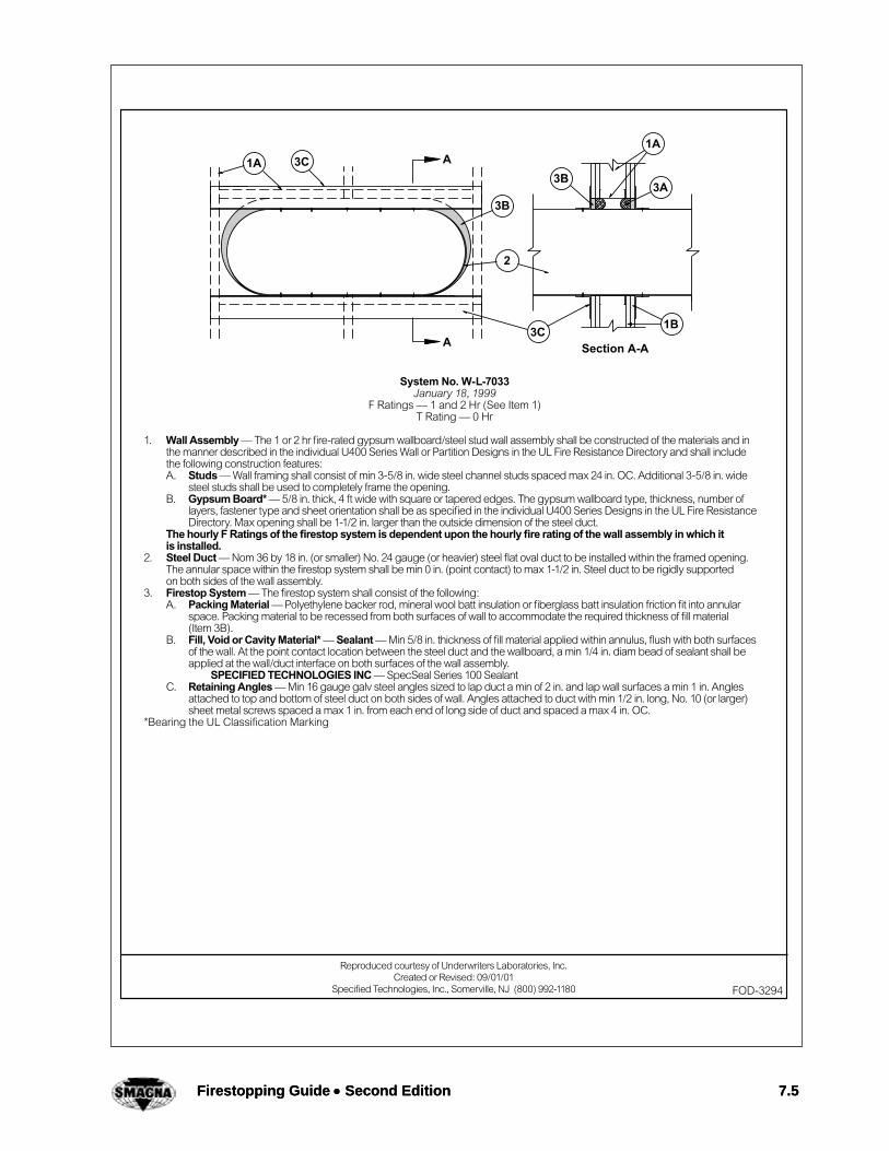
System No. W-L-7033January 18, 1999
F Ratings — 1 and 2 Hr (See Item 1)T Rating — 0 Hr
1. Wall Assembly — The 1 or 2 hr fi re-rated gypsum wallboard/steel stud wall assembly shall be constructed of the materials and in the manner described in the individual U400 Series Wall or Partition Designs in the UL Fire Resistance Directory and shall include the following construction features: A. Studs — Wall framing shall consist of min 3-5/8 in. wide steel channel studs spaced max 24 in. OC. Additional 3-5/8 in. wide
steel studs shall be used to completely frame the opening.B. Gypsum Board* — 5/8 in. thick, 4 ft wide with square or tapered edges. The gypsum wallboard type, thickness, number of
layers, fastener type and sheet orientation shall be as specifi ed in the individual U400 Series Designs in the UL Fire Resistance Directory. Max opening shall be 1-1/2 in. larger than the outside dimension of the steel duct.
The hourly F Ratings of the fi restop system is dependent upon the hourly fi re rating of the wall assembly in which it is installed.
2. Steel Duct — Nom 36 by 18 in. (or smaller) No. 24 gauge (or heavier) steel fl at oval duct to be installed within the framed opening. The annular space within the fi restop system shall be min 0 in. (point contact) to max 1-1/2 in. Steel duct to be rigidly supported on both sides of the wall assembly.
3. Firestop System — The fi restop system shall consist of the following: A. Packing Material — Polyethylene backer rod, mineral wool batt insulation or fi berglass batt insulation friction fi t into annular
space. Packing material to be recessed from both surfaces of wall to accommodate the required thickness of fi ll material (Item 3B).
B. Fill, Void or Cavity Material* — Sealant — Min 5/8 in. thickness of fi ll material applied within annulus, fl ush with both surfaces of the wall. At the point contact location between the steel duct and the wallboard, a min 1/4 in. diam bead of sealant shall be applied at the wall/duct interface on both surfaces of the wall assembly.
SPECIFIED TECHNOLOGIES INC — SpecSeal Series 100 SealantC. Retaining Angles — Min 16 gauge galv steel angles sized to lap duct a min of 2 in. and lap wall surfaces a min 1 in. Angles
attached to top and bottom of steel duct on both sides of wall. Angles attached to duct with min 1/2 in. long, No. 10 (or larger) sheet metal screws spaced a max 1 in. from each end of long side of duct and spaced a max 4 in. OC.
*Bearing the UL Classifi cation Marking
Reproduced courtesy of Underwriters Laboratories, Inc.Created or Revised: 09/01/01
Specifi ed Technologies, Inc., Somerville, NJ (800) 992-1180 FOD-3294

7.6 Firestopping Guide • Second Edition 7.6 Firestopping Guide • Second Edition
System No. W-J-7011December 16, 1998
F Rating — 2 HrT Rating — 3/4 Hr
1. Wall Assembly — Min 6 in. thick reinforced lightweight or normal weight (100-150 pcf) concrete. Wall may be constructed of any UL Classifi ed Concrete Blocks*. Rectangular opening in wall to be max 4-3/4 in. higher and wider than steel duct (Item 2). Max area of opening is 364 sq in. with a max single dimension of 22-3/4 in.
See Concrete Blocks (CAZT) category in the Fire Resistance Directory for names of manufacturers.2. Steel Duct — Nom 18 by 12 in. (or smaller) No. 24 gauge (or heavier) steel duct to be installed within the opening. Min clearance
between the duct and the edge of opening in wall is 1-1/2 in. Steel duct to be rigidly supported on both sides of the wall assembly.3. Batt and Blankets* — Max 1-1/2 in. thick light density (min 3/4 pcf) glass fi ber blanket insulation jacketed on the outside with
a foil-scrim-kraft facing. Longitudinal and transverse joints sealed with foil-scrim-kraft tape. During the installation of the blanket insulation, blanket to be compressed approx 50 percent in thickness such that the annular space within the fi restop system shall be min 1/2 in. to max 2 in.
See Batts and Blankets (BKNV) category in the Building Materials Directory for names of manufacturers. Any batt or blanket meeting the above specifi cations and bearing the UL Classifi cation Marking with a Flame Spread Index of 25 or less and a Smoke Developed Index of 50 or less may be used.
4. Firestop System — The fi restop system shall consist of the following: A. Fill, Void or Cavity Material* — Wrap Strap — Nom 1/4 in. thick intumescent material faced on both sides with a plastic fi lm,
supplied in 1-1/2 in. wide strips. Single layer of wrap strip wrapped around to compress the duct insulation (Item 3) with the ends butted and and held in place by means of two layers of foil tape. Wrap strip installed such that 1-1/4 in. of the wrap strip extends into the wall. One set of wrap strips to be installed on each side of the wall.
SPECIFIED TECHNOLOGIES INC — SpecSeal RED Wrap StripB. Fill, Void or Cavity Material* — Sealant — Min 5/8 in. thickness of fi ll material applied within annulus, fl ush with both surfaces
of the wall. A min 1/4 in. bead of fi ll material shall be applied at the wrap strip/ insulated through-penetrant interface on both sides of the wall.
SPECIFIED TECHNOLOGIES INC — SpecSeal 100, 101,102 or 105 Sealant*Bearing the UL Classifi cation Marking
Reproduced courtesy of Underwriters Laboratories, Inc.Created or Revised: 09/01/01
Specifi ed Technologies, Inc., Somerville, NJ (800) 992-1180 FOD-3289

Firestopping Guide • Second Edition 7.7 Firestopping Guide • Second Edition 7.7

7.8 Firestopping Guide • Second Edition 7.8 Firestopping Guide • Second Edition

Firestopping Guide • Second Edition 7.9 Firestopping Guide • Second Edition 7.9

7.10 Firestopping Guide • Second Edition 7.10 Firestopping Guide • Second Edition

Firestopping Guide • Second Edition 7.11 Firestopping Guide • Second Edition 7.11

3M Fire Protection Products This material was extracted by 3M Fire Protection Products from the 2006 edition of the UL Fire Resistance Directory.
7.12 Firestopping Guide • Second Edition
This material was extracted and drawn by 3M Fire Protection Products from the 2006 edition of the UL Fire Resistance Directory.
Insu
late
d P
ipes
Thro
ugh
Pene
tratio
ns50
00 S
erie
sG
ypsu
m
3Fire Protection Productswww.3m.com/firestop
Product Support Line: 1-800-328-1687Choose option 4 for FAX ON DEMAND 469
WL
System No. W-L-5001May 19, 2005
F Ratings – 1 and 2 Hr (See Item 1)T Ratings – 3/4, 1 and 1-1/2 Hr (See Item 3)
L Rating At Ambient – 2 CFM/sq ftL Rating At 400 F – less than 1 CFM/sq ft
1. Wall Assembly – The 1 or 2 hr fire-rated gypsum board/stud wall assembly shall be constructed of the materials and in the manner described in the individual U300, U400 or V400 Series Wall or Partition Design in the UL Fire Resistance Directory and shall include the following construction features:
A. Studs – Wall framing may consist of either wood studs or steel channel studs. Wood studs to consist of nom 2 in. by 4 in. (25 mm by 102 mm) lumber spaced 16 in. (406 mm) OC with nom 2 by 4 in. lumber end plates and cross braces. Steel studs to be min 3-5/8 in. (92 mm) wide by 1-3/8 in. (35 mm) deep channels spaced max 24 in. (610 mm) OC.
B. Gypsum Board* – Nom 5/8 in. (16 mm) thick, 4 ft (122 cm) wide with square or tapered edges. The gypsum board type, thickness, number of layers, fastener type and sheet orientation shall be as specified in the individual U300 or U400 Series Design in the UL Fire Resistance Directory. Max diam of opening is 14-1/2 in (368 mm) for wood stud walls and 18 in. (457 mm) for steel stud walls.
The hourly F Rating of the firestop system is 1 hr when installed in a 1 hr fire rated wall and 2 hr when installed in a 2 hr fire rated wall.
2. Through Penetrants – One metallic pipe or tubing to be centered within the firestop system. Pipe or tubing to be rigidly supported on both sides of wall assembly. The following types and sizes of metallic pipes or tubing may be used:
A. Steel Pipe – Nom 12 in. (305 mm) diam (or smaller) Schedule 10 (or heavier) steel pipe.B. Copper Tubing – Nom 6 in. (152 mm) diam (or smaller) Type L (or heavier) copper tubing.C. Copper Pipe – Nom 6 in. (152 mm) diam (or smaller) Regular (or heavier) copper pipe.
3. Pipe Covering* – Nom 1 in. or 2 in. (25 mm or 51 mm) thick hollow cylindrical heavy density glass fiber units jacketed on the outside with an all service jacket. Longitudinal joints sealed with metal fasteners or factory-applied self-sealing lap tape. Transverse joints sealed with metal fasteners or with butt strip tape supplied with the product. When nom 1 in. (25 mm) thick pipe covering is used, the annular space between the pipe covering and the circular cutout in the gypsum board layers on each side of the wall shall be min 1/4 in. to max 3/8 in. (6 mm to max 10 mm). When nom 2 in. (51 mm) thick pipe covering is used, the annular space between the pipe covering and the circular cutout in the gypsum board layers on each side of the wall shall be min 1/2 in. to max 3/4 in. (13 mm to max 19 mm).
See Pipe and Equipment Covering – Materials (BRGU) category in Building Materials Directory for names of manufacturers. Any pipe covering material meeting the above specifications and bearing the UL Classification Marking with a Flame Spread Index of 25 or less and a Smoke Developed Index of 50 or less may be used.
The hourly T Rating of the firestop system is 3/4 hr when nom 1 in. (25 mm) thick pipe covering is used. The hourly T Rating of the firestop system is 1 hr and 1-1/2 hr when nom 2 in. (51 mm) thick pipe covering is used with 1 hr and 2 hr fire rated walls, respectively.
4. Firestop System – Installed symmetrically on both sides of wall assembly. The details of the firestop system shall be as follows:
A. Fill, Void or Cavity Materials* – Wrap Strip – Nom 1/4 in. (6 mm) thick intumescent elastomeric material faced on one side with aluminum foil, supplied in 2 in. (51 mm) wide strips. Nom 2 in. (51 mm) wide strip tightly wrapped around pipe covering (foil side out) with seam butted. Wrap strip layer securely bound with steel wire or aluminum foil tape and slid into annular space approx 1-1/4 in. (32 mm) such that approx 3/4 in. (19 mm) of the wrap strip width protrudes from the wall surface. One layer of wrap strip is required when nom 1 in. (25 mm) thick pipe covering is used. Two layers of wrap strip are required when nom 2 in. (51 mm) thick pipe covering is used.
3M COMPANY – FS-195+
B. Fill, Void or Cavity Materials* – Caulk or Sealant – Min 1/4 in. (6 mm) diam continuous bead applied to the wrap strip/wall interface and to the exposed edge of the wrap strip layer approx 3/4 in. (19 mm) from the wall surface.
3M COMPANY – CP 25WB+, IC 15WB+, FireDam 150+ caulk or FB-3000 WT sealant
*Bearing the UL Classification Marking
W-L-5001 • 1 of 1

3M Fire Protection Products This material was extracted by 3M Fire Protection Products from the 2006 edition of the UL Fire Resistance Directory.
Firestopping Guide • Second Edition 7.13
This material was extracted and drawn by 3M Fire Protection Products from the 2006 edition of the UL Fire Resistance Directory.
Met
alli
c Pip
esTh
roug
h Pe
netra
tions
1000
Ser
ies
Con
cret
e
3Fire Protection Productswww.3m.com/firestop
Product Support Line: 1-800-328-1687Choose option 4 for FAX ON DEMAND 33
CA
J
System No. C-AJ-1009December 07, 1999
(Formerly System No. 122)F Rating – 2 HrT Rating – 0 Hr
L Rating At Ambient – Less Than 1 CFM/sq ft (See Item 5)L Rating At 400 F – Less Than 1 CFM/sq ft (See Item 5)
1. Floor or Wall Assembly – Min 5 in. thick reinforced normal weight (100-150 pcf) concrete. Wall may also be constructed of any UL Classified Concrete Blocks*. Max diam of opening is 6 in.
See Concrete Blocks (CAZT) category in the Fire Resistance Directory for names of manufacturers.
2. Metallic Sleeve (Optional) – Nom 6 in. diam (or smaller) electrical metallic tubing, steel conduit or cast iron pipe cast or grouted into floor or wall assembly, flush with floor or wall surfaces.
3. Through Penetrants – One metallic pipe or conduit to be centered within the firestop system. A nom annular space of 3/4 in. is required within the firestop system. Pipe or conduit to be rigidly supported on both sides of floor or wall assembly. The following types and sizes of metallic pipes or conduits may be used:
A. Steel Pipe – Nom 4 in. diam (or smaller) Schedule 5 (or heavier) steel pipe.
B. Conduit – Nom 4 in. (or smaller) diam steel electrical metallic tubing or steel conduit.
4. Packing Material – Min 3 in. thickness of min 4 pcf mineral wool batt insulation firmly packed into opening as a permanent form. Packing material to be recessed from top surface of floor as required to accommodate the required thickness of fill material. Packing material to be centered in walls mid depth and recessed to allow for installation of fill material.
5. Fill, Void or Cavity Material* – Sealant – Min 1/2 in. thickness of fill material applied within the annulus, flush with top surface of floor. In walls, fill material to be applied on each side of packing material.
3M COMPANY – FB-2000 or FB-2000+ (floors only). (Note: L Ratings apply only when FB-2000+ is used.)
*Bearing the UL Classification Marking
C-AJ-1009 • 1 of 1
3M Fire Protection Products This material was extracted by 3M Fire Protection Products from the 2006 edition of the UL Fire Resistance Directory.
7.14 Firestopping Guide • Second Edition
This material was extracted and drawn by 3M Fire Protection Products from the 2006 edition of the UL Fire Resistance Directory.
Met
alli
c Pip
esTh
roug
h Pe
netra
tions
1000
Ser
ies
Con
cret
e
3Fire Protection Productswww.3m.com/firestop
Product Support Line: 1-800-328-1687Choose option 4 for FAX ON DEMAND 41
CA
J
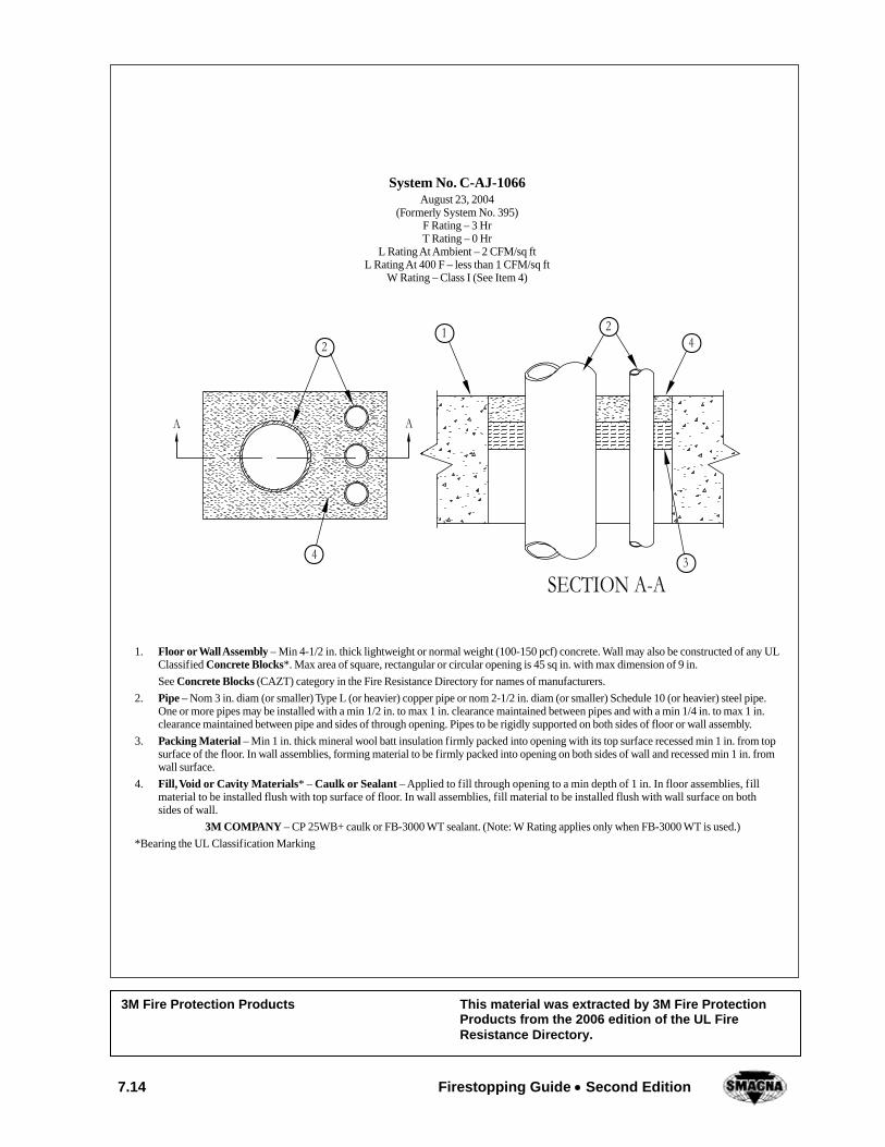
System No. C-AJ-1066August 23, 2004
(Formerly System No. 395)F Rating – 3 HrT Rating – 0 Hr
L Rating At Ambient – 2 CFM/sq ftL Rating At 400 F – less than 1 CFM/sq ft
W Rating – Class I (See Item 4)
1. Floor or Wall Assembly – Min 4-1/2 in. thick lightweight or normal weight (100-150 pcf) concrete. Wall may also be constructed of any UL Classified Concrete Blocks*. Max area of square, rectangular or circular opening is 45 sq in. with max dimension of 9 in.
See Concrete Blocks (CAZT) category in the Fire Resistance Directory for names of manufacturers.
2. Pipe – Nom 3 in. diam (or smaller) Type L (or heavier) copper pipe or nom 2-1/2 in. diam (or smaller) Schedule 10 (or heavier) steel pipe. One or more pipes may be installed with a min 1/2 in. to max 1 in. clearance maintained between pipes and with a min 1/4 in. to max 1 in. clearance maintained between pipe and sides of through opening. Pipes to be rigidly supported on both sides of floor or wall assembly.
3. Packing Material – Min 1 in. thick mineral wool batt insulation firmly packed into opening with its top surface recessed min 1 in. from top surface of the floor. In wall assemblies, forming material to be firmly packed into opening on both sides of wall and recessed min 1 in. from wall surface.
4. Fill, Void or Cavity Materials* – Caulk or Sealant – Applied to fill through opening to a min depth of 1 in. In floor assemblies, fill material to be installed flush with top surface of floor. In wall assemblies, fill material to be installed flush with wall surface on both sides of wall.
3M COMPANY – CP 25WB+ caulk or FB-3000 WT sealant. (Note: W Rating applies only when FB-3000 WT is used.)
*Bearing the UL Classification Marking
C-AJ-1066 • 1 of 1

Firestopping Guide • Second Edition 7.15 Firestopping Guide • Second Edition 7.15
1
System No. W-J-7007F Rating — 2 Hr
T Rating — 1/2 Hr
1. Wall Assembly — Min 6 in. thick reinforced lightweight or normal weight (100-150 pcf) concrete. Wall may also be constructed of any UL Classified Concrete Blocks*. Max area of opening is 73.67 sq ft with max dimension of 104 in.
See Concrete Blocks (CAZT) category in the Fire Resistance Directory for names of manufacturers.2. Steel Duct — Nom 100 in. by 100 in. (or smaller) No. 24 gauge (or heavier) galv steel duct to be installed either concentrically or
eccentrically within the firestop system. The space between the steel duct and periphery or opening shall be min 0 in. (point contact) to max 2 in. Steel duct to be rigidly supported on both sides of the wall assembly.
3. Firestop System — The firestop system shall consist of the following: A. Packing Material — (Optional, Not Shown) — Polyethylene backer rod, mineral wool batt insulation or fiberglass batt insulation
friction fitted into annular space of opening. Packing material to be recessed from both surfaces of wall as required thickness of fill material.
B. Fill, Void or Cavity Material* — Sealant — Min 5/8 in. thickness of fill material applied within the annulus, flush with both surfaces of wall. At the point contact location between steel duct and concrete wall, a min 1/4 in. diam bead of fill material shall be applied at the concrete/steel duct interface on both surfaces of wall assembly.
SPECIFIED TECHNOLOGIES INC — SpecSeal 100, 101, 102, 105, 120 or 129 Sealant C. Steel Retaining Angles — Min No. 16 gauge galv steel angles sized to lap steel duct a min of 2 in. and lap wall surfaces a min 1
in. Angles attached to steel duct on both sides of wall with min No. 10 by 1/2 in. long steel sheet metal screws spaced a max of 1 in. from each end of steel duct and spaced a max 6 in. OC.
*Bearing the UL Classification Mark
Reproduced courtesy of Underwriters Laboratories, Inc.Created or Revised: 11/13/02
Specified Technologies, Inc., Somerville, NJ (800) 992-1180
3B
12
3B3C
A
A
Section A-A
FOD-3237

7.16 Firestopping Guide • Second Edition 7.16 Firestopping Guide • Second Edition

Firestopping Guide • Second Edition 7.17 Firestopping Guide • Second Edition 7.17

7.18 Firestopping Guide • Second Edition 7.18 Firestopping Guide • Second Edition
System No. C-AJ-7027September 18, 1996
F Rating — 2 HrT Rating — 0 Hr
1. Floor or Wall Assembly — Min 4-1/2 in. thick reinforced lightweight or normal weight (100-150 pcf) concrete. Wall may also be constructed of any UL Classifi ed Concrete Blocks*. Max area of opening is 364 sq in. with max dimensions of 26 in.
See Concrete Blocks (CAZT) category in the Fire Resistance Directory for names of manufacturers.2. Steel Duct — Nom 24 by 12 in. (or smaller) No. 24 gauge (or heavier) steel duct. One duct to be installed within the fi restop system
with a nom 1 in. annular space. Steel duct to be rigidly supported on both sides of fl oor or wall assembly.3. Firestop System — The fi restop system shall consist of the following:
A. Packing Material — Min 2 in. thickness of min 4 pcf mineral wool batt insulation fi rmly packed into opening as a permanent form. Packing material to be recessed from top surface of fl oor and from both surfaces of wall as required to accommodate the required thickness of fi ll material.
B. Fill, Void or Cavity Material* — Sealant — Min 1 in. thickness of fi ll material applied within the annulus, fl ush with top surface of fl oor and both surfaces of wall.
SPECIFIED TECHNOLOGIES INC — SpecSeal 100, 101, 102 or 105 SealantC. Steel Angle — Min 2 in. wide by 2 in. high by 0.108 in. thick steel angle cut to fi t the contour of the duct with a 1 in. lap on
the top surface of fl oor or both surfaces of wall. Legs of angles secured to duct with min two No. 12 by 3/4 in. sheet metal screws per side, spaced a max 4 in. OC.
*Bearing the UL Classifi cation Marking
Reproduced courtesy of Underwriters Laboratories, Inc.Created or Revised: 09/01/01
Specifi ed Technologies, Inc., Somerville, NJ (800) 992-1180 FOD-3080

Firestopping Guide • Second Edition 7.19 Firestopping Guide • Second Edition 7.19
System No. W-L-7060October 04, 2000
F Ratings — 1 and 2 Hr (See Item 1)T Rating — 0 Hr
1. Wall Assembly — The 1 or 2 hr fi re-rated gypsum board/stud wall assembly shall be constructed of the materials and in the manner specifi ed in the individual U300 or U400 Series Wall or Partition Design in the UL Fire Resistance Directory and shall include the following construction features: A. Studs — Wall framing may consist of either wood studs or steel channel studs. Wood studs to consist of nom 2 by 4 in. lumber
spaced 16 in. OC. Steel studs to be min 3-5/8 in. wide and spaced max 24 in. OC. Additional horizontal framing members installed to form a rectangular box around the steel duct (Item 2).
B. Gypsum Board* — Thickness, type, number of layers and fasteners as specifi ed in the individual Wall and Partition Design. When wood studs are used, interior of through opening to be lined with sheets of gypsum board around entire periphery to a total thickness of 5/8 in. or 1-1/4 in. for 1 or 2 hr wall assemblies, respectively. Max area of opening is 364 sq in. with a max dim of 26 in.
The hourly F Rating of the fi restop system is equal to the hourly fi re rating of the wall assembly in which it is installed.2. Steel Duct — Nom 12 by 24 in. (or smaller) No. 24 gauge (or heavier) galv steel duct installed eccentrically or concentrically within
opening. Annular space between duct and periphery of opening to be min 0 in. (point contact) to max 2 in. Duct to be rigidly supported on both sides of the wall assembly.
3. Firestop System — The fi restop system shall consist of the following: A. Packing Material — Min 4 pcf mineral wool batt insulation compressed and tightly packed to min 3-5/8 in. or 4-7/8 in.
thickness for 1 or 2 hr fi re-rated assemblies, respectively. Packing material recessed from both surfaces of wall as required to accommodate fi ll material (Item 3B).
B. Fill, Void or Cavity Material* — Sealant — Min 5/8 in. thickness of fi ll material applied within annulus, fl ush with both surfaces of wall assembly. At point contact location, min 1/4 in. diam bead of fi ll material applied at steel duct/gypsum board interface on both surfaces of wall.
SPECIFIED TECHNOLOGIES INC — SpecSeal LCI SealantC. Retaining Angles — Min 16 GA galv steel angles sized to lap duct a min of 2 in. and lap periphery of opening a min 1 in.
Angles attached to all four sides of steel duct on both surfaces of wall with No. 10 (or larger) steel sheet metal screws spaced 1 in. from each end and max 4 in. OC.
*Bearing the UL Classifi cation Marking
Reproduced courtesy of Underwriters Laboratories, Inc.Created or Revised: 09/01/01
Specifi ed Technologies, Inc., Somerville, NJ (800) 992-1180 FOD-3462

3M Fire Protection Products This material was extracted by 3M Fire Protection Products from the 2006 edition of the UL Fire Resistance Directory.
7.20 Firestopping Guide • Second Edition
CA
JC
oncrete2000 Series
Non-M
etallic P
ipes
Through Penetrations
1563Fire Protection Productswww.3m.com/firestop
Product Support Line: 1-800-328-1687Choose option 4 for FAX ON DEMAND
This material was extracted and drawn by 3M Fire Protection Products from the 2006 edition of the UL Fire Resistance Directory.
System No. C-AJ-2003May 18, 2005
F Rating – 3 HrT Rating – 1/2 Hr
L Rating at Ambient – 15 CFM/sq ftL Rating at 400 F – less than 1 CFM/sq ft
1. Floor or Wall Assembly – Min 4-1/2 in. (114 mm) thick lightweight or normal weight (100-150 pcf or 1600-2400 kg/m3) concrete. Wall may also be constructed of any UL Classified Concrete Blocks*. Max area of rectangular or square opening 64 sq in. (413 sq cm) with max dimension of 8 in. (203 mm). Max diam of circular opening is 8 in. (203 mm).
See Concrete Blocks (CAZT) category in the Fire Resistance Directory for names of manufacturers.
2. Steel Sleeve (Optional) – Min 3/16 in. (5 mm) thick steel welded to form a four sided square or rectangular sleeve. For circular openings, steel sleeve to consist of nom 8 in. (203 mm) diam (or smaller) Schedule 40 (or heavier) steel pipe.
3. Nonmetallic Pipe or Conduit – Nom 2 in. (51 mm) diam (or smaller) Schedule 40 polyvinyl chloride (PVC) pipe for use in closed (process or supply) or vented (drain, waste or vent) piping systems or Rigid Nonmetallic Conduit++ or SDR13.5 chlorinated polyvinyl chloride (CPVC) pipe for use in closed (process or supply) piping systems. One pipe to be installed within the firestop system. A min 1 in. to max 3 in. (25 mm to max 76 mm) annular space is required within the firestop system. Pipe to be rigidly supported on both sides of the floor or wall assembly.
4. Firestop System – The firestop system shall consist of the following:
A. Fill, Void or Cavity Material* – Intumescent Sheet – Rigid aluminum foil-faced sheet with galv steel sheet backer. Diam of hole cut in sheet to accommodate pipe to be 1 in. (25 mm) larger than diam of pipe such that a uniform 1/2 in. (13 mm) space is present between the pipe and perimeter of the sheet cutout. Sheet cut to lap a min of 2 in. (51 mm) on the concrete on all sides of the through opening. A max of one slit may be made in the sheet to permit installation of the sheet about the pipe. The slit shall be made perpendicular to the side of the sheet nearest the circular cutout and shall intersect with the circular cutout in line with the center of the cutout. Sheet to be installed with the galv steel sheet backer exposed (aluminum foil facing against floor or wall surface). Sheet secured to top surface of floor and to both surfaces of wall using 1/4 in. (6 mm) diam by steel expansion bolts in conjunction with steel nuts and min 1-1/4 in. (32 mm) diam steel washers. Max spacing of fasteners not to exceed 6 in. (152 mm) OC. with additional fasteners required max 1 in. (25 mm) from both sides of slit made to permit installation of sheet about pipe. Prior to installation of the sheet(s), a nom 1/4 in. (6 mm) diam bead of caulk or putty (Item D) shall be applied to the top surface of the floor and on both surfaces of the wall around the perimeter of the through opening. Min 2 in. (51 mm) wide strip of min 0.016 in. (0.41 mm) thick (30 gauge) galv steel sheet to be centered over slit in sheet and secured to galv steel sheet backer on both sides of slit with steel sheet metal screws located max 1/2 in. (13 mm) from edge of cutout and max 1/2 in. (13 mm) from edge of through opening. Prior to installation of the steel cover strip, the slit in the sheet shall be covered with a nom 1/4 in. (6 mm) diam bead of caulk or putty (Item D).
3M COMPANY – CS-195+
B. Fill, Void or Cavity Materials* – Wrap Strip – Nom 1/4 in. (6 mm) thick intumescent elastomeric material faced on one side with aluminum foil, supplied in 2 in. (51 mm) wide strips. Nom 2 in. (51 mm) wide strips tightly wrapped around nonmetallic pipe (foil side exposed). Two layers of wrap strip are required. Each layer of wrap strip to be installed with butted seam with butted seam of second layer offset from butted seam of first layer. Wrap strip layers temporarily held in position using aluminum foil tape, steel wire tie, or equivalent. In wall assemblies, the wrap strip is to be installed in the same manner used for floor assemblies, but it shall be installed symmetrically on both sides of wall assembly.
3M COMPANY – FS-195+
C-AJ-2003 • 1 of 2

3M Fire Protection Products This material was extracted by 3M Fire Protection Products from the 2006 edition of the UL Fire Resistance Directory.
Firestopping Guide • Second Edition 7.21
This material was extracted and drawn by 3M Fire Protection Products from the 2006 edition of the UL Fire Resistance Directory.
Non-M
eta
llic
Pip
esTh
roug
h Pe
netra
tions
2000
Ser
ies
Con
cret
e
3Fire Protection Productswww.3m.com/firestop
Product Support Line: 1-800-328-1687Choose option 4 for FAX ON DEMAND 157
CA
J
C. Steel Collar – Nom 1-1/4 in. (32 mm) deep collar with 1-1/4 in. (32 mm) wide by 2 in. (51 mm) long anchor tabs and 1/2 in. (13 mm) long tabs to retain wrap strip layers. Coils of precut 0.016 in. (0.41 mm) thick (30 gauge) galv sheet steel available from pipe wrap manufacturer. As an alternate, collar may be field-fabricated from min 0.016 in. (0.41 mm) thick (30 gauge) galv sheet steel in accordance with instruction sheet supplied by wrap strip manufacturer. Steel collar, with anchor tabs bent outward 90 degrees and with retainer tabs bent inward 90 degrees wrapped tightly around wrap strip layers with min 1 in. (25 mm) overlap at seam. Steel collar and wrap strip slid into cutout in intumescent sheet such that the bottom edges of wrap strip layers and steel collar project 1 in. (25 mm) below top plane of floor and such that anchor tabs rest on top surface of intumescent sheet. Secure anchor tabs to galv steel sheet backer of intumescent sheet with steel sheet metal screws. Compress wrap strip layers around pipe above intumescent sheet using a min 1/2 in. (13 mm) wide by 0.028 in. (0.71 mm) thick stainless steel band clamp with worm drive tightening mechanism. Steel collar not required for firestops in wall assemblies. Instead, the wrap strip layers are slid into cutout in intumescent sheet on each side of wall such that the exposed edges of wrap strip layers project 1 in. (25 mm) from exposed face of intumescent sheet. Compress wrap strip layers around pipe using a min 1/2 in. (13 mm) wide by 0.028 in. (0.71 mm) thick stainless steel band clamp with worm drive tightening mechanism at the projecting wrap strip midheight.
D. Fill, Void or Cavity Materials* – Caulk or Sealant – Generous application of caulk to be applied to the base of the wrap strip at its egress from the intumescent sheet(s) in addition to coating all exposed seams in wrap strip layers. Nom 1/4 in. (6 mm) bead of caulk to be applied to slit in intumescent sheet(s) prior to installation of steel cover strip.
3M COMPANY – CP 25WB+ caulk or FB-3000WT sealant. (CP 25WB+ not suitable for use with CPVC pipes.)
E. Fill, Void or Cavity Materials* – Graphite Seal, Caulk, Sealant or Putty (Not Shown) – One layer of 1/2 in. x 1/16 in. (13 mm x 1.6 mm) adhesive backed graphite intumescent seal positioned under intumescent sheet around entire perimeter of through opening or min 1/4 in. (6 mm) diam continuous bead of caulk or putty applied to edge of intumescent sheet at its interface with surface of floor or wall around entire perimeter of through opening.
3M COMPANY – E-FIS or Ultra GS seals, CP 25WB+, IC 15WB+ caulk, FB-3000WT sealant or MP+ Stix putty.(Note: CP 25WB+ not suitable for use with CPVC pipes.)
+Bearing the UL Listing Mark*Bearing the UL Classification Marking
System No. C-AJ-2003 continued
C-AJ-2003 • 2 of 2

7.22 Firestopping Guide • Second Edition 7.22 Firestopping Guide • Second Edition

Firestopping Guide • Second Edition 7.23 Firestopping Guide • Second Edition 7.23

7.24 Firestopping Guide • Second Edition 7.24 Firestopping Guide • Second Edition
System No. W-J-1099October 11, 2000F Rating — 2 Hr
T Ratings — 1/4, 3/4 and 1 Hr (See Item 3)
1. Wall Assembly — Min 6 in. thick reinforced lightweight or normal weight (100-150 pcf) concrete. Wall may also be constructed of any UL Classifi ed Concrete Blocks*. Max diam of opening is 2 in. larger than OD of through penetrant.
See Concrete Blocks (CAZT) category in the Fire Resistance Directory for names of manufacturers.2. Steel Sleeve — Cylindrical sleeve fabricated from 0.0125 in thick (30 gauge) galv sheet steel and having a min 2 in. lap along
the longitudinal seam. Length of the sleeve to be equal to or max 2 in. greater than the thickness of the wall. Sleeve installed by coiling the sheet steel to a diam smaller than the through opening, inserting the coil through the opening and releasing the coil to let it uncoil against the circular opening in concrete. The ends of the steel sleeve shall be fl ush with or extend a max 1 in. beyond each surface of the wall.
As an alternate, steel sleeve may consist of nom 10 in. diam (or smaller) Schedule 5 (or heavier) steel pipe sleeve cast or grouted into concrete. The ends of the steel sleeve shall be fl ush with or extend a max 1 in. beyond each surface of the wall.
3. Through Penetrant — One metallic pipe, conduit or tube to be installed eccentrically or concentrically within the fi restop system. The annular space between the pipe, conduit or tube and the steel sleeve shall be min 0 in. (point contact) to max 2 in. Pipe, conduit or tube to be rigidly supported on both sides of the wall assembly. The following types and sizes of metallic pipes, conduits and tubes may be used: A. Steel Pipe — Nom 8 in. diam (or smaller) Schedule 5 (or heavier) steel pipe.B. Iron Pipe — Nom 8 in. diam (or smaller) cast or ductile iron pipe.C. Conduit — Nom 6 in. diam (or smaller) rigid steel conduit, nom 4 in. diam (or smaller) steel electrical metallic tubing (EMT) or
nom 4 in. diam (or smaller) fl exible steel conduit.D. Copper Pipe — Nom 4 in. diam (or smaller) Regular (or heavier) copper pipe.E Copper Tube — Nom 4 in. diam (or smaller) Type L (or heavier) copper tube. Type of Penetrant Max Diam T Rating Steel or iron pipe, steel conduit or EMT 2 in. 1 hr Steel or iron pipe, steel conduit or EMT 8 in. 3/4 hr Copper pipe or tube 4 in. 1/4 hr
3A. Through Penetrating Product* — Flexible Metal Piping — As an alternate to Item 3, one nom 2 in. diam (or smaller) steel fl exible metal pipe to be installed either concentrically or eccentrically within the fi restop system. The annular space between the pipe, conduit or tube and the steel sleeve shall be min 0 in. (point contact) to max 2 in. Pipe to be rigidly supported on both sides of the wall assembly. When fl exible metal piping is used, T Rating is 1 hr.
OMEGA FLEX INC TITEFLEX CORP A BUNDY CO WARD MFG INC
4. Firestop System — The fi restop system consists of the following items: A. Packing Material — Min 1 in. thickness of min 4 pcf mineral wool batt insulation compressed and tightly packed into each end
of steel sleeve. Packing material recessed from each end of steel sleeve. When alternate steel pipe sleeve is used, packaging material may be omitted from the fi restop system.
B. Fill, Void or Cavity Material* — Sealant — Min 5/8 in. thickness of fi ll material applied within annulus, fl ush with each end of steel sleeve. At point contact location, min 1/4 in. diam bead of fi ll material applied at metallic pipe/steel sleeve interface on both surfaces of wall. Optionally, a min 1/4 in. diam bead of fi ll material shall be applied around the circumference of the steel sleeve at its egress from each side of the wall.
SPECIFIED TECHNOLOGIES INC — SpecSeal LCI Sealant*Bearing the UL Classifi cation Marking
Reproduced courtesy of Underwriters Laboratories, Inc.Created or Revised: 09/01/01
Specifi ed Technologies, Inc., Somerville, NJ (800) 992-1180 FOD-3431

Firestopping Guide • Second Edition 7.25 Firestopping Guide • Second Edition 7.25
Reproduced courtesy of Underwriters Laboratories, Inc.Created or Revised: 09/01/01
Specifi ed Technologies, Inc., Somerville, NJ (800) 992-1180 FOD-3078
System No. C-AJ-7023January 06, 1999F Rating — 2 HrT Rating — 0 Hr
1. Floor or Wall Assembly — Min 4-1/2 in. thick reinforced lightweight or normal weight (100-150 pcf) concrete. Wall may also be constructed of any UL Classifi ed Concrete Blocks*. Max diam of opening is 8 in.
See Concrete Block (CAZT) category in the Fire Resistance Directory for names of manufacturers.2. Steel Duct — Nom 6 in. diam (or smaller) No. 28 gauge (or heavier) steel duct or nom 4 in. diam (or smaller) No. 30 gauge (or
heavier) steel duct. One steel duct to be installed either concentrically or eccentrically within the fi restop system. The annular space between the steel duct and the periphery of the opening shall be min 1/4 in. to a max 1-3/4 in. Steel duct to be rigidly supported on both sides of fl oor or wall assembly.
3. Firestop System — The fi restop system shall consist of the following: A. Packing Material — Min 2 in. thickness of min 4 pcf mineral wool batt insulation fi rmly packed into opening as a permanent
form. Packing material to be recessed from top surface of fl oor or from both surfaces of wall as required to accommodate the required thickness of fi ll material.
B. Fill, Void or Cavity Material* — Sealant — Min 1/2 in. thickness of fi ll material applied within the annulus, fl ush with top surface of fl oor or with both surfaces of wall assembly.
SPECIFIED TECHNOLOGIES INC — SpecSeal 100, 101, 102 or 105 Sealant*Bearing the UL Classifi cation Marking

SHEET METAL AND AIR CONDITIONING CONTRACTORS’NATIONAL ASSOCIATION, INC.