gl - mercedes-benz usaour company and staff congratulate you on the purchase of your new...
TRANSCRIPT

GLOperator’s Manual
X164_AKB; 5; 31, en-USd2ureepe, Version: 2.11.8.1
2009-09-11T12:30:16+02:00 - Seite 1

SymbolsTrademarks®:RAdBlue® is a registered trademark of the
German Association of the AutomotiveIndustry (VDA).RBabySmartTM is a trademark of Siemens
Automotive Corp.RBluetooth® is a registered trademark of
Bluetooth SIG Inc.RESP® and PRE-SAFE® are registered
trademarks of Daimler.RHomeLink® is a registered trademark of
Prince, a Johnson Controls Company.RSIRIUS and related marks are trademarks
of SIRIUS XM Radio Inc.The following symbols are found in thisOperator’s Manual:
G Warning!Warning notices draw your attention tohazards that may endanger your health or life,or the health or life of others.
! Highlights hazards that may result indamage to your vehicle.
i Helpful hints or further information youmay find useful.
X This symbol points to instructionsfor you to follow.
X A number of these symbolsappearing in succession indicatesa multiple-step procedure.
Y page This symbol tells you where to lookfor further information on a topic.
YY This continuation symbol marks awarning or procedure which iscontinued on the next page.
Display Text in displays, such as the controlsystem, are printed in the typeshown here.
X164_AKB; 5; 31, en-USd2ureepe, Version: 2.11.8.1
2009-09-11T12:30:16+02:00 - Seite 2

Our company and staff congratulate you onthe purchase of your new Mercedes-Benz.Your selection of our product is ademonstration of your trust in our companyname. Furthermore, it exemplifies your desireto own an automobile that will be as easy aspossible to operate and will provide years ofservice.Your Mercedes-Benz represents the efforts ofmany skilled engineers and craftsmen. Tohelp assure your driving pleasure, and alsothe safety of you and your passengers, we askyou to make a small investment of time:RPlease read this manual carefully, then
return it to your vehicle where it will behandy for your reference.RPlease follow the recommendations
contained in this manual. They aredesigned to acquaint you with theoperation of your Mercedes-Benz.RPlease pay attention to the warnings and
cautions contained in this manual. They aredesigned to help improve the safety of thevehicle operator and occupants.
We extend our best wishes for many miles ofsafe, pleasurable driving.Mercedes-Benz USA, LLCA Daimler Company
1645841583 É1645841583&ËÍ
X164_AKB; 5; 31, en-USd2ureepe, Version: 2.11.8.1
2009-09-11T12:30:16+02:00 - Seite 1

X164_AKB; 5; 31, en-USd2ureepe, Version: 2.11.8.1
2009-09-11T12:30:16+02:00 - Seite 2

Index ....................................................... 4
Introduction ......................................... 20
At a glance ........................................... 25
Safety and security ............................. 35
Controls in detail ................................. 69
Operation ........................................... 225
Practical hints ................................... 283
Technical data ................................... 359
Contents 3
X164_AKB; 5; 31, en-USd2ureepe, Version: 2.11.8.1
2009-09-11T12:30:16+02:00 - Seite 3

1, 2, 3 ...115V AC Socket ................................. 2133-zone automatic climate control
see Climate control system 4-ETS (Electronic Traction System) . . . 644MATIC
see All-wheel drive (4MATIC)
AABS (Antilock Brake System) ............. 62
Indicator lamp ................................ 315Messages in the multifunctiondisplay ................................... 288, 300
Accessory weight .............................. 254Accidents ........................................... 112
Air bags ........................................... 37Distance warning function ............. 155Emergency calls (Tele Aid) ............. 215NECK-PRO active front headrestraints ........................................ 53
Active Bi-Xenon headlampsMessages in the multifunctiondisplay ........................................... 310see Headlamps
Adaptive Damping Systemsee ADS
AdBlue® ...................................... 346, 373Capacity, AdBlue® tank ................. 369Refilling ......................................... 347
Additives Engine oil ....................................... 371Gasoline ......................................... 372
Address change ................................... 22ADS (Adaptive Damping System) ..... 159Advanced Tire PressureMonitoring System (AdvancedTPMS) ................................................. 239
Messages in the multifunctiondisplay ................................... 297, 313
Air bags ................................................ 37Emergency call upon deployment . . 215Front, driver and passenger ............. 40Front passenger front air bag offindicator lamp (Canadaonly) ........................................ 46, 322
Front passenger front air bag offindicator lamp (USA only) ........ 42, 322Knee bag .......................................... 40Messages in the multifunctiondisplay ........................................... 291OCS (Occupant ClassificationSystem) ........................................... 42Safety guidelines ............................. 39Side impact ...................................... 41Window curtain ................................ 42
Air conditioning refrigerant andlubricant ............................................. 371Air distribution .......................... 178, 188Air filter .............................................. 309Air pressure
see Tire inflation pressure Air pressure (tires) ............................ 255Air recirculation mode .............. 180, 190Air suspension program
Comfortable driving style ............... 159Introduction ................................... 159Messages in the multifunctiondisplay ........................................... 301Sporty driving style ........................ 159Suspension tuning ......................... 159Vehicle level control ...................... 159
Air volume ................................. 179, 189Alarm system
see Anti-theft systems Alignment bolt (vehicle toolkit) .............................................. 284, 343All-wheel drive (4MATIC) .................. 166Alternator
Messages in the multifunctiondisplay ................................... 296, 308
Alternator (Technical data)see Vehicle specification
Anticorrosion/antifreeze .................. 374Antilock Brake System
see ABS Anti-theft systems ............................... 66
Anti-theft alarm system ................... 66Immobilizer ...................................... 66
Aquaplaningsee Hydroplaning
Armrest, front Storage compartment .................... 208
4 Index
X164_AKB; 5; 31, en-USd2ureepe, Version: 2.11.8.1
2009-09-11T12:30:16+02:00 - Seite 4

Ashtrays ............................................. 211Aspect ratio (tires) ............................ 255Audio/DVD menu .............................. 129Auto-dimming rear view mirrors ........ 94Automatic central locking .......... 74, 138Automatic headlamp mode ................ 98Automatic interior lighting control .. 101Automatic locking when driving ...... 138Automatic transmission ................... 114
Emergency operation (limp-homemode) ............................................ 119Gear range indicator ...................... 118Gear ranges ................................... 118Gear selector lever ........................ 114Hill-start assist system .................. 155Kickdown ....................................... 117One-touch gearshifting .................. 118Shifting procedure ......................... 116Steering wheel gearshift control .... 118Towing a trailer .............................. 118Transmission position indicator ..... 116Transmission positions .................. 116
AUX socket ........................................ 207Axle oils .............................................. 369
BBabySmart™
Air bag deactivation system ............. 46Self-test ........................................... 47
Backrestsee Seats
Backup lamps Messages in the multifunctiondisplay ........................................... 310
Bar (air pressure unit) ....................... 255BAS (Brake Assist System) ................. 63Batteries, SmartKey
Checking condition .......................... 73Replacing ....................................... 326
Battery, Vehicle ................................. 348Charging ........................................ 350Jump starting ................................. 350Messages in the multifunctiondisplay ................................... 296, 308
Bead (tire) .......................................... 255Beverage holders
see Cup holders
Bleeding the fuel system (dieselengine) ............................................... 345BlueTEC
AdBlue® tank ................................. 346AdBlue® tank capacity ................... 369
Brake fluid Checking level ............................... 233Messages in the multifunctiondisplay ........................................... 300
Brake lamps Cleaning lenses ............................. 277
Brake pads Messages in the multifunctiondisplay ........................................... 299
Brakes ................................................ 260Parking brake ........................ 112, 261Warning lamp ................................. 316
Break-in period .................................. 226Bug cover (Radiator) ......................... 230Bulbs
see Replacing bulbs
CCAC (Customer Assistance Center) ... 23California retail buyers andlessees, important notice for ............. 21Calls (phone) ...................................... 142Can holders
see Cup holders Capacities and recommendedfuel/lubricants .................................. 368Cargo compartment
Cargo net ....................................... 206Cargo volume, expanding .............. 201Cover blind .................................... 205Fuse box ........................................ 357Hooks ............................................ 201Tie-down rings ............................... 200
Cargo compartment cover blind ...... 205Cargo net ........................................... 206Cargo tie-down rings ......................... 200Carpets, cleaning .............................. 280Carriers .............................................. 196Center console
Lower part ....................................... 33Upper part ....................................... 31
Index 5
X164_AKB; 5; 31, en-USd2ureepe, Version: 2.11.8.1
2009-09-11T12:30:16+02:00 - Seite 5

Central locking Automatic ................................ 74, 138KEYLESS-GO .................................... 71Locking/unlocking from inside ........ 75SmartKey ......................................... 70
Central locking/unlocking switch ..... 75Certification label .............................. 360Children in the vehicle
Air bags ........................................... 37BabySmart™ air bag deactivationsystem ............................................. 46Child safety locks (rear doors) ......... 60Child seat anchors – LATCH-type ... . 59Indicator lamp, front passengerfront air bag off (Canada only) ......... 46Indicator lamp, front passengerfront air bag off (USA only) .............. 42Infant and child restraint systems .... 56OCS (Occupant ClassificationSystem) ........................................... 42Override switch ................................ 60Safety notes ..................................... 55Tether anchorage points .................. 58Top tether ........................................ 58
Child safetysee Children in the vehicle
Child seat anchors – LATCH-typesee Children in the vehicle
Chrome-plated exhaust tip,cleaning .............................................. 281Cigarette lighter ................................ 212Climate control system .................... 172
3-zone automatic climate control . . 181Air conditioning ..................... 177, 186Air conditioning refrigerant ............ 371Air distribution ....................... 178, 188Air recirculation mode ........... 180, 190Air volume ............................. 179, 189Automatic mode .................... 178, 187Climate control .............................. 175Deactivating system .............. 177, 185Front defroster ...................... 179, 189Residual heat andventilation .............................. 180, 191Temperature .......................... 178, 187
Clock ............................................ 28, 135Cockpit ................................................. 27Cold tire inflation pressure .............. 255
Collapsible wheel chock ................... 286COMAND system
see separate COMAND systemoperating instructions
Combination switch .......................... 100Comfort submenu
Easy-entry/exit feature .................. 139Fold-in function for exterior rearview mirrors ................................... 140Seat belt adjustment feature ......... 139
Compass Calling up ....................................... 223
Control system .................................. 125Multifunction display ..................... 127Multifunction steering wheel ......... 125Resetting to factory settings .......... 132
Control system menus ...................... 127Audio/DVD .................................... 129Distronic ........................................ 131Navigation ..................................... 130Off-road ......................................... 131Settings ......................................... 132Standard display ............................ 128Telephone ...................................... 142Trip computer ................................ 141Vehicle configuration ..................... 140Vehicle status message memory . . . 131
Control system submenus Comfort ......................................... 139Instrument cluster ......................... 133Lighting .......................................... 136Time/Date ..................................... 135Vehicle ........................................... 138
Coolant Anticorrosion/antifreeze ............... 374Capacities ...................................... 369Checking level ............................... 231Messages in the multifunctiondisplay ........................................... 306
Cruise control .................................... 144Activating ....................................... 145Canceling ....................................... 146Changing the set speed ................. 146Last stored speed .......................... 147Lever .............................................. 145Messages in the mutlifunctiondisplay ........................................... 294
6 Index
X164_AKB; 5; 31, en-USd2ureepe, Version: 2.11.8.1
2009-09-11T12:30:16+02:00 - Seite 6

Resume function ............................ 147Setting current speed .................... 145
Cup holders ........................................ 209Curb weight ....................................... 255Customer Assistance Center (CAC) ... 23Customer Relations Department ....... 23
DDashboard
see Instrument cluster Data recording ..................................... 24Date, Setting ...................................... 135Daytime running lamp mode .............. 99
Switching on or off ......................... 136Deep water
see Standing water Defroster
Rear window .................................. 191Windshield ............................. 179, 189
Delayed shut-off Exterior lamps ................................ 137Interior lighting .............................. 138
Department of Transportationsee DOT
Diesel engine Preglow indicator lamp .................... 29
Diesel fuelsee Fuel
Differential locks ............................... 121A few words about ......................... 122Messages in the multifunctiondisplay ................................... 123, 302Switching ....................................... 122
Difficulties While driving .................................. 111With starting .................................. 110
Digital clocksee Clock
Digital speedometer ......................... 129Dimensions (vehicle)
see Vehicle specification Direction of rotation (tires) .............. 246Displays
Digital speedometer ...................... 129Distronic ........................................ 149Maintenance service indicator ....... 273
Messages in the multifunctiondisplay ........................................... 287Multifunction display ..................... 127Outside temperature ............. 129, 135Symbol messages .......................... 299Text messages ............................... 288Trip computer ................................ 141Vehicle status message memory . . . 131Vehicle system settings ................. 132
Distronic ............................................ 147Cleaning system sensor cover ....... 278Control system .............................. 131Distance warning function ............. 155Distance warninglamp ...................................... 149, 319Driving with .................................... 153Menu ............................................. 150Messages in the multifunctiondisplay ........................................... 294Resume function ............................ 152Sensor cover .................................. 278Speed settings ............................... 151
Door control panel .............................. 34Door handles ........................................ 34Doors
Child safety locks ............................ 60Locking/unlocking (KEYLESS-GO) ... 71Locking/unlocking (SmartKey) ........ 70Messages in the multifunctiondisplay ........................................... 304Opening from inside ......................... 74Remote door unlock (Tele Aid) ....... 219Unlocking (Mechanical key) ........... 323
DOT (Department ofTransportation) .................................. 255Downhill Speed Regulation
see DSR Drinking and driving ......................... 259Driving
Abroad ........................................... 272Hydroplaning ................................. 262Instructions ........................... 108, 259In winter ........................................ 258Off-road ......................................... 262Problems ....................................... 111Safety systems ................................ 61Systems ......................................... 144
Index 7
X164_AKB; 5; 31, en-USd2ureepe, Version: 2.11.8.1
2009-09-11T12:30:16+02:00 - Seite 7

Through standing water ................. 262With Distronic ................................ 153
Driving and parking Safety notes .................................. 108
Driving off .................................. 110, 261Driving safety systems ....................... 61
4-ETS ............................................... 64ABS .................................................. 62BAS .................................................. 63EBP .................................................. 63ESP® ................................................ 63
Driving systems Air suspension program ................. 159All-wheel drive (4MATIC) ................ 166Cruise control ................................ 144Distronic ........................................ 147Downhill Speed Regulation (DSR) . . 155Hill-start assist system .................. 155Off-road driving program ............... 158Parktronic system .......................... 166Rear view camera .......................... 169
Driving tips, automatictransmission ...................................... 117DSR (Downhill Speed Regulation) .... 155
Messages in the multifunctiondisplay ........................................... 303
EEasy-entry/exit feature .............. 92, 139EBP (Electronic BrakeProportioning) ...................................... 63Electrical system
Improper work on ormodifications ................................... 23Power outlets ................................. 212
Electrical system (Technical data)see Vehicle specification
Electronic Stability Programsee ESP®
Electronic Traction Systemsee 4-ETS
Emergency, in case of First aid kit ..................................... 284Flat tire .......................................... 336Hazard warning flasher .................. 101Roadside Assistance ................ 21, 216Towing the vehicle ......................... 352
Emergency calls Tele Aid .......................................... 215
Emergency engine shutdown ........... 357Emergency operations
Limp-home mode ........................... 119Remote door unlock (Tele Aid) ....... 219
Emergency Tensioning Devicesee ETD
Emission control ............................... 272Information label ............................ 361System warranties ........................... 20
Engine Break-in recommendations ............ 226Cleaning ......................................... 276Compartment ................................ 228Malfunction indicatorlamp ........................................ 29, 320Messages in the multifunctiondisplay ........................................... 306Number .......................................... 361Starting .......................................... 108Turning off ..................................... 113
Engine (Technical data)see Vehicle specification
Engine compartment Radiator ......................................... 230
Engine coolantsee Coolant
Engine oil Adding ........................................... 231Additives ........................................ 371Checking level ............................... 230Consumption ................................. 230Messages in the multifunctiondisplay ........................................... 308Oil dipstick ..................................... 230Recommended engine oils and oilfilter ............................................... 370
ESP® (Electronic StabilityProgram) .............................................. 63
4-ETS ............................................... 64Messages in the multifunctiondisplay ................................... 289, 300Off-road ESP® .................................. 65Trailer stabilization ........................... 65Warning lamp ................................. 318
8 Index
X164_AKB; 5; 31, en-USd2ureepe, Version: 2.11.8.1
2009-09-11T12:30:16+02:00 - Seite 8

ETD (Emergency TensioningDevice) ................................................. 52
Safety guidelines ............................. 39Express operation
Power windows .............................. 105Tilt/sliding sunroof ........................ 192
Exterior lamp switch ........................... 97Exterior rear view mirrors .................. 94
Fold-in function ........................ 95, 140Parking position ............................... 95Power-folding ................................... 95
Exterior view of vehicle ...................... 26
FFastening the seat belts ..................... 50First aid kit ......................................... 284Flat tire ............................................... 336
Lowering the vehicle ...................... 344Mounting the spare wheel ............. 340Preparing the vehicle ..................... 336Spare wheel ........................... 336, 368TIREFIT (tire repair kit) ................... 337
Floormats ........................................... 223Fluids
AdBlue® ......................................... 369Automatic transmission fluid ......... 369Brake fluid ..................................... 369Capacities ...................................... 368Engine coolant ............................... 369Engine oil ....................................... 369Power steering fluid ....................... 369Washer and headlamp cleaningsystem ........................................... 370
Fog lamps ............................................. 99Messages in the multifunctiondisplay ................................... 310, 312
Fold-in function for exterior rearview mirrors ................................ 95, 140Four-wheel drive
see All-wheel drive (4MATIC) Front air bags
see Air bags Front axle oil ...................................... 369Front lamps
see Headlamps
Front passenger front air bag ............ 40Messages in the multifunctiondisplay ........................................... 291
Front passenger front air bag offindicator lamp (Canada only) ..... 46, 322Front passenger front air bag offindicator lamp (USA only) .......... 42, 322Front seat head restraints
see Head restraints Fuel ..................................................... 226
Additives ........................................ 372Capacity, fuel tank ......................... 369Diesel fuel ............................. 369, 372Drive sensibly–safe fuel ................. 259Fuel consumption statistics ........... 141Fuel filler flap and cap ................... 227Fuel tank reserve warninglamp ........................................ 29, 320Premium unleaded gasoline ... 369, 371Refueling ........................................ 226Requirements ................................ 371
Fuel filler flap ..................................... 227Opening manually .......................... 324
Fuels, coolants, lubricants etc. Capacities ...................................... 368
Fuel system, bleeding (dieselengine) ............................................... 345Fuel tank
Capacity ........................................ 369Fuel filler flap and cap ................... 227Refueling ........................................ 226
Fuses .................................................. 355
GGarage door opener .................... 33, 219Gasoline
see Fuel GAWR (Gross Axle Weight Rating) ... 255Gear range ......................................... 118
Indicator ........................................ 118Limiting .......................................... 119Shifting into optimal ...................... 119Transfer case ................................. 120
Gear selector lever ............................ 114Cleaning ......................................... 280Gearshift pattern ........................... 114Shifting procedure ......................... 116
Index 9
X164_AKB; 5; 31, en-USd2ureepe, Version: 2.11.8.1
2009-09-11T12:30:16+02:00 - Seite 9

Transmission position indicator ..... 116Transmission positions .................. 116
Generatorsee Alternator
Global locking/unlockingsee Key, SmartKey
Glove box ........................................... 207Gross Axle Weight Rating
see GAWR Gross Trailer Weight
see GTW Gross Vehicle Weight
see GVW Gross Vehicle Weight Rating
see GVWR GTW (Gross Trailer Weight) .............. 255GVW (Gross Vehicle Weight) ............ 255GVWR (Gross Vehicle WeightRating) ................................................ 255
HHalogen headlamps
see Headlamps Hard plastic trim items, cleaning .... 279Hazard warning flasher .................... 101Headlamp cleaning system .............. 101Headlamps
Active Bi-Xenon headlamps ............. 97Adjusting aim ................................. 333Automatic headlamp mode .............. 98Bi-Xenon .................................. 97, 329Cleaning lenses ............................. 277Cleaning system ............................ 101Daytime running lamp mode ............ 99Delayed shut-off ............................ 137Halogen ......................................... 329High-beam flasher ......................... 101High-beam headlamps ................... 100Low-beam headlamps ...................... 98Replacing bulbs ............................. 328Switch .............................................. 97
Headliner, cleaning and care of ....... 280Head restraints .................................... 82
Adjustment ................................ 82, 84Comfort head restraint .................... 84
NECK-PRO active front headrestraints ......................................... 53NECK-PRO active front headrestraints, resetting ....................... 325
Heated steering wheel ........................ 93Height adjustment
Seat belt outlet ................................ 51Seats ............................................... 82Vehicle level control ...................... 159
High-beam flasher ............................. 101High-beam headlamps .............. 100, 329
Indicator lamp .................................. 29Hill-start assist system ..................... 155Hinged quarter windows .................. 106Hood ................................................... 228
Messages in the multifunctiondisplay ........................................... 304
Hooks ................................................. 201Horn ...................................................... 27HVAC
see Climate control system Hydroplaning ..................................... 262
IIdentification labels .......................... 360Identification number, vehicle(VIN) ................................................... 361Ignition ......................................... 80, 109Immobilizer .......................................... 66Indicator lamps
see Lamps, indicator and warning Infant and child restraint systems
see Children in the vehicle Inflation pressure
see Tires, Inflation pressure Infrared reflecting windshield ......... 223Inside door handle .............................. 74Instrument cluster ............................ 124
Illumination .................................... 124Lamps ............................................ 314Multifunction display ..................... 127
Instrument lightingsee Instrument cluster, Illumination
Instrument panelsee Instrument cluster
Instruments and controlssee Cockpit
10 Index
X164_AKB; 5; 31, en-USd2ureepe, Version: 2.11.8.1
2009-09-11T12:30:16+02:00 - Seite 10
Interior lighting Delayed shut-off ............................ 138Emergency lighting ........................ 102Front .............................................. 101Front reading lamps ....................... 101Rear ............................................... 102Rear reading lamps ........................ 102
Interior rear view mirror ..................... 93Auto-dimming rear view mirrors ....... 94
Interior storage spacessee Storage compartments
Intermittent wiping Rain sensor .................................... 103
JJack ..................................................... 286Jump starting ..................................... 350
KKey, Mechanical
Loss of ............................................. 73Replacing ......................................... 74Unlocking/locking manually .......... 323
Key, SmartKey Battery check lamp .......................... 73Checking batteries ........................... 73Factory setting ........................... 71, 72Global locking (KEYLESS-GO) .................................................. 73Global locking (SmartKey) ................ 71Global unlocking (KEYLESS-GO) ............................................ 72, 73Global unlocking(SmartKey) ....................................... 71Important notes on KEYLESS-GO ..... 72Locking/unlocking ........................... 70Loss of ............................................. 73Messages in the multifunctiondisplay ........................................... 304Opening and closing the powertilt/sliding sunroof ......................... 107Opening and closing the windows . 107Remote control ................................ 70Replacing ......................................... 74Replacing batteries ........................ 326Restoring to factory setting ....... 71, 73
Selective setting ........................ 71, 73Starter switch positions ................... 80
KEYLESS-GO Starter switch positions ................... 80
Kickdown ........................................... 117Kilopascal (air pressure unit) ........... 255Knee bag .............................................. 40
LLabels
Certification ................................... 360Emission control information ......... 361Tire and Loading Informationplacard ........................................... 242Tire inflation pressure .................... 236
Lamps, exterior Exterior lamp switch ........................ 97Front .............................................. 329Messages in the multifunctiondisplay ........................................... 310Rear ............................................... 329Switching on/off .............................. 97
Lamps, indicator and warning ABS .......................................... 28, 315Brakes ..................................... 28, 316Center console ................................ 31Differential locks ............................ 123Distance warninglamp .............................. 149, 155, 319Engine malfunction .................. 29, 320ESP® ........................................ 28, 318Fog lamps ........................................ 99Front passenger front air bag off(Canada only) .......................... 46, 322Front passenger front air bag off(USA only) ................................ 42, 322Fuel tank reserve ..................... 29, 320High-beam headlamps ............. 29, 100Instrument cluster ................... 28, 314Low-beam headlamps ................ 29, 98Low tire pressure/TPMSmalfunction telltale .................. 28, 321Seat belt telltale ................ 29, 51, 317SRS .................................... 29, 36, 318Turn signals ..................................... 28
Language, selecting .......................... 134
Index 11
X164_AKB; 5; 31, en-USd2ureepe, Version: 2.11.8.1
2009-09-11T12:30:16+02:00 - Seite 11

LATCH-type child seat anchorssee Children in the vehicle
License plate lamps Messages in the multifunctiondisplay ........................................... 311Replacing bulbs ............................. 330
Light alloy wheels, cleaning ............. 279Lighter
see Cigarette lighter Lighting ................................................ 97
Daytime running lamp mode ............ 99Exterior ............................................ 97Interior ........................................... 101
Limp-home mode .............................. 119Load index (tires) ...................... 251, 255Loading
see Vehicle loading Locator lighting ................................. 136Lock button
Outside door handle (KEYLESS-GO) .................................................. 73
Locking the vehicle KEYLESS-GO .................................... 71Manually ........................................ 324SmartKey ......................................... 70
Loss of Key .................................................. 73Service and Warranty Informationbooklet .......................................... 360
Low-beam headlamps ......................... 98Exterior lamp switch ........................ 97Indicator lamp .................................. 29Switching on .................................... 98
LOW RANGE mode ............................. 120Messages in the multifunctiondisplay ........................................... 303Switching ....................................... 121
Lubricants .......................................... 368Lumbar support ................................... 87
MMaintenance ........................................ 21Maintenance System
Service indicator display ................ 274Service indicator message ............. 273Service term exceeded .................. 274
Manual headlamp mode (Low-beam headlamps) ................................ 98Maximum engine speed
see Vehicle specification Maximum loaded vehicle weight ..... 256Maximum load rating (tires) ............. 255Maximum permissible tireinflation pressure .............................. 256Mechanical key .................................. 323Media interface ................................. 207Memory function ................................. 96Menus
see Control system menus Minispare wheel
see Spare wheel Mirrors .................................................. 93
Auto-dimming rear view mirrors ....... 94Exterior rear view mirror parkingposition ............................................ 95Exterior rear view mirrors ................ 94Interior rear view mirror ................... 93Memory function .............................. 96Power-folding exterior rear viewmirrors ............................................. 95Vanity mirror .................................. 210
MOExtended system ......................... 345MOExtended tires ..................... 345, 365MON (Motor Octane Number) .......... 371Motor Octane Number
see MON Multicontour seat ................................ 90Multifunction display ........................ 127
Symbol messages .......................... 299Text messages ............................... 288Vehicle status messages ............... 287
Multifunction display messages ABS ....................................... 288, 300Active headlamps .......................... 310Advanced TPMS ..................... 297, 313Air bags ......................................... 291Air filter .......................................... 309Air suspension program ................. 301Alternator .............................. 296, 308Automatictransmission .................................. 296Battery ................................... 296, 308Brake fluid ..................................... 300
12 Index
X164_AKB; 5; 31, en-USd2ureepe, Version: 2.11.8.1
2009-09-11T12:30:16+02:00 - Seite 12

Brake pads ..................................... 299Coolant .......................................... 306Cruise control ................................ 294Differential locks ................... 123, 302Distronic ........................................ 294Doors ............................................. 304Downhill Speed Regulation (DSR) . . 303EBP ................................................ 300Engine oil ....................................... 308ESP® ...................................... 289, 300Fog lamps .............................. 310, 312Front passenger front air bag ........ 291Gas cap .......................................... 309High-beam lamps ........................... 311Hood .............................................. 304License plate lamps ....................... 311Light sensor ................................... 311Low-beam lamps ............................ 312LOW RANGE mode ......................... 303Parking brake ................................ 300Parking lamps ................................ 311PRE-SAFE® .................................... 290Reserve fuel ................................... 309Reverse lamp ................................. 310Side marker lamps ......................... 311SmartKey ....................................... 304SmartKey with KEYLESS-GO .......... 304SRS ................................................ 301Tailgate .......................................... 304Tail lamps ...................................... 312Tele Aid .......................................... 301Tire inflation pressure ............ 297, 313Tire pressure monitor .................... 297Tires ...................................... 297, 313Trailer brake lamps ........................ 312Trailer tail lamps ............................ 312Trailer turn signal lamps ................ 312Turn signals ................................... 313Washer fluid ................................... 305
Multifunction steering wheel Adjustment ...................................... 91Buttons .......................................... 125Cleaning ......................................... 280Easy-entry/exit feature ........... 92, 139Gearshift control ............................ 118Heating ............................................ 93Memory function .............................. 96Overview .......................................... 30
NNavigation menu ............................... 130Navigation system
see Separate operating instructions NECK-PRO active front headrestraints ............................................. 53
Resetting ....................................... 325Nets, parcel ....................................... 200Night security illumination .............. 137Normal occupant weight .................. 256Number, vehicle identification(VIN) ................................................... 361
OOccupant Classification System
see OCS (Occupant ClassificationSystem)
Occupant distribution ....................... 256Occupant safety
Air bags ........................................... 37BabySmart™ .................................... 46Children and air bags ....................... 37Children in the vehicle ..................... 55Child seat anchors – LATCH-type ... . 59Fastening the seat belts ................... 50Front passenger front air bag offindicator lamp (Canadaonly) ........................................ 46, 322Front passenger front air bag offindicator lamp (USA only) ........ 42, 322Infant and child restraint systems .... 56Introduction ..................................... 36OCS (Occupant ClassificationSystem) ........................................... 42PRE-SAFE® ....................................... 52Seat belts .................................. 39, 48
OCS (Occupant ClassificationSystem) ................................................ 42
Self-test ........................................... 45Odometer ........................................... 127Off-road driving ................................. 262
Checklist ............................... 264, 268Crossing obstacles ........................ 267Driving instructions ........................ 262Driving on sand .............................. 267Driving through water .................... 266
Index 13
X164_AKB; 5; 31, en-USd2ureepe, Version: 2.11.8.1
2009-09-11T12:30:16+02:00 - Seite 13
Returning ....................................... 268Ruts ............................................... 267Steep terrain .................................. 264
Off-road driving program .................. 158Off-road menu ................................... 131Oil, oil level
see Engine oil On-board computer
see Control system One-touch gearshifting ..................... 118Operating safety .................................. 23Ornamental moldings, cleaning ....... 277Outside temperature
see Displays Overhead control panel ...................... 33
PPaintwork, cleaning .......................... 276Paintwork code ................................. 361Panic alarm .......................................... 61Panorama roof
Sunshade ....................................... 211Parcel nets ......................................... 200Parking ............................................... 112
Parktronic system .......................... 166Parking brake ............................ 112, 261
Messages in the multifunctiondisplay ........................................... 300
Parking position Exterior rear view mirrors ................ 95Transmission position .................... 116
Parktronic system Cleaning system sensors ............... 278Malfunction .................................... 169Minimum distance ......................... 167Sensor range ................................. 167Switching on/off ........................... 168System sensors ............................. 167Warning indicators ................... 27, 168
Parts service ...................................... 360PASS AIR BAG OFF indicator lamp(Canada only)
see Front passenger front air bagoff indicator lamp (Canada only)
PASS AIR BAG OFF indicator lamp(USA only)
see Front passenger front air bagoff indicator lamp (USA only)
Passenger safetysee Occupant safety
Pedals ................................................. 259Phone
see Telephone Plastic parts, cleaning ...................... 279Power assistance .............................. 259Power outlets .................................... 212Power seats
see Seats Power tailgate
Closing ............................................. 76Messages in the multifunctiondisplay ........................................... 304Opening ........................................... 76
Power tilt/sliding sunroof Operation ....................................... 192Synchronizing ................................ 194
Power washer .................................... 276Power windows ................................. 105
Cleaning ......................................... 278Door windows ................................ 106Hinged quarter windows ................ 106Operation ....................................... 105Rear door window, overrideswitch .............................................. 60Synchronizing ................................ 107
Practical hints ................................... 284Preglow indicator lamp .............. 29, 109PRE-SAFE® ............................................ 52
Messages in the multifunctiondisplay ........................................... 290
Problems While driving .................................. 111With vehicle ..................................... 23With wipers .................................... 105
Product information ............................ 20Production options weight ............... 256Proximity key
see Key, SmartKey PSI (air pressure unit) ....................... 256
14 Index
X164_AKB; 5; 31, en-USd2ureepe, Version: 2.11.8.1
2009-09-11T12:30:16+02:00 - Seite 14

RRadiator ..................................... 230, 257Radio
Selecting stations .......................... 129Radio transmitters ............................ 272Rain sensor
see Intermittent wiping Rear axle oil ....................................... 369Rear center console ashtray
see Ashtrays Rear doors
Child safety locks ............................ 60Rear door window
Override switch ................................ 60Rear fog lamp
see Fog lamps Rear lamps
see Tail lamps Rear seats
see Seats Rear view camera .............................. 169
Cleaning the camera lens .............. 278Rear window defroster ..................... 191Rear window wiper/washer ............. 104Recommended tire inflationpressure ..................................... 234, 256Refilling
AdBlue® ......................................... 347Refrigerant, air conditioning ............ 371Refueling ............................................ 226Regular checks .................................. 228Reminder, Seat belt
see Seat belts, Telltale Remote control
see Key, SmartKey Remote door unlock (Tele Aid) ......... 219Replacing
Key .................................................. 74Replacing bulbs ................................. 328Reporting safety defects .................... 24Research Octane Number
see RON Reserve fuel
Messages in the multifunctiondisplay ........................................... 309Warning lamp ................................... 29
Reset button ................................ 28, 124
Reset tool (NECK-PRO active fronthead restraints) ................................. 325Restraint systems
see Occupant safety Rims ........................................... 256, 365Roadside Assistance ................... 21, 216RON (Research Octane Number) ..... 371Rubber parts, cleaning ...................... 279Run-flat tires
see MOExtended tires
SSafety
Driving safety systems ..................... 61Occupant safety ............................... 36Reporting defects ............................ 24
Safety beltssee Seat belts
Seat belt force limiter ......................... 52Seat belts ............................................. 48
Adjustment function ........................ 51Children in the vehicle ..................... 55Cleaning ......................................... 280Fastening ......................................... 50Height adjustment ........................... 51Proper use of ................................... 49Safety guidelines ............................. 39Safety notes ..................................... 48Telltale ..................................... 29, 317
Seat heating ......................................... 90Seating capacity ................................ 243Seats ..................................................... 82
Adjustment ...................................... 82Easy-entry/exit feature .................... 92Folding (expanding cargo volume) . 201Heating ............................................ 90Memory function .............................. 96Multicontour seat ............................ 90Rear seats ........................................ 87Ventilation ....................................... 90
Securing cargo Cargo tie-down rings ...................... 200
Selective settingsee Key, SmartKey
Selector leversee Gear selector lever
Index 15
X164_AKB; 5; 31, en-USd2ureepe, Version: 2.11.8.1
2009-09-11T12:30:16+02:00 - Seite 15

Self-test BabySmart™ .................................... 47OCS (Occupant ClassificationSystem) ........................................... 45Tele Aid .......................................... 215
Servicesee Maintenance
Service, parts .................................... 360Service and warranty information ..... 20Service intervals
see Maintenance System, Serviceindicator message
Service life (tires) .............................. 247Settings
Factory setting (KEYLESS-GO) ......... 72Factory setting (SmartKey) .............. 71Memory function .............................. 96Menu ............................................. 132Selective setting (KEYLESS-GO) ....... 73Selective setting (SmartKey) ............ 71
Side impact air bags ........................... 41Side marker lamps
Cleaning lenses ............................. 277Messages in the multifunctiondisplay ........................................... 311
Sidewall (tires) .................................. 256Side windows
see Power windows SmartKey
see Key, SmartKey SmartKey with KEYLESS-GO
see Key, SmartKey Snow chains ...................................... 258Snow tires
see Winter tires Spare wheel ....................................... 365
Mounting ....................................... 340Storage location ............................ 286
Speedometer ............................... 28, 149Speed settings
Cruise control ................................ 145Distronic ........................................ 151Resume function ................... 147, 152
Sport Utility Vehiclesee SUV
SRS Indicator lamp ................... 29, 36, 318Messages in the multifunctiondisplay ........................................... 301
Standing water, driving through ...... 262Starter switch positions
KEYLESS-GO .................................... 80SmartKey ......................................... 80
Starting difficulties (engine) ............ 110Starting the engine ........................... 108Steering column
see Multifunction steering wheel,Adjustment
Steering wheelsee Multifunction steering wheel
Steering wheel gearshift control ..... 118Stolen Vehicle Recovery Services . . . 219Storage compartments ..................... 207Storing tires ....................................... 248Stranded vehicle ............................... 355Sunroof
see Power tilt/sliding sunroof Sunshade
Rear panorama roof ....................... 211Sun visors .......................................... 210Suspension tuning
see Air suspension program SUV (Sport Utility Vehicle) ................. 22
TTachometer .................................. 29, 125
Overspeed range ........................... 125Tailgate
Closing ............................................. 75Messages in the multifunctiondisplay ........................................... 304Opening ........................................... 75Power tailgate .................................. 76
Tail lamps ........................................... 329Cleaning lenses ............................. 277Messages in the multifunctiondisplay ........................................... 312
Tar stains ........................................... 276Technical data
Air conditioning refrigerant ............ 371Brake fluid ..................................... 371
16 Index
X164_AKB; 5; 31, en-USd2ureepe, Version: 2.11.8.1
2009-09-11T12:30:16+02:00 - Seite 16

Capacities fuels, coolants,lubricants etc. ................................ 368Coolant .......................................... 373Engine oil additives ........................ 371Engine oils ..................................... 370Fuel requirements .......................... 371Gasoline additives .......................... 372Identification labels ....................... 360Premium unleaded gasoline ........... 371Rims and tires ................................ 365Spare wheel ................................... 368Vehicle specificationGL 350 BlueTEC ............................. 362Vehicle specification GL 450 ......... 362Vehicle specification GL 550 ......... 363Washer and headlamp cleaningsystem ................................... 370, 375
Technical data (dimensions)see Vehicle specification
Technical data (electrical system)see Vehicle specification
Technical data (engine)see Vehicle specification
Technical data (weights)see Vehicle specification
Tele Aid ............................................... 214Emergency calls ............................. 215Information button ......................... 217Initiating an emergency callmanually ........................................ 216Messages in the multifunctiondisplay ........................................... 301Remote door unlock ...................... 219Roadside Assistance button .......... 216Search & Send ............................... 218SOS button .................................... 216Stolen Vehicle Recovery Services . . 219System self-test ............................. 215
Telephone ............................................. 30Answering/ending a call ................ 143Hands-free microphone ................... 34Menu ............................................. 142Operation ....................................... 142Phone book .................................... 143Redialing ........................................ 144
Temperature Interior temperature .............. 178, 187Outside .................................. 129, 135
Tether anchorage pointssee Children in the vehicle
Tie-down rings ................................... 200Tightening torque
Wheels ........................................... 344Time setting ....................................... 135TIN (Tire Identification Number) ...... 256Tire and Loading Informationplacard ............................................... 242Tire and loading terminology ........... 254TIREFIT ............................................... 337Tire Identification Number
see TIN Tire inflation pressure
Checking ........................................ 237Important notes on ........................ 235Label on the inside of fuel fillerflap ................................................ 236Placard on driver’s door B-pillar ..... 242
Tire labeling ....................................... 250Tire load rating .................................. 255Tire ply composition and materialused .................................................... 256Tire pressure loss warning system . 237Tire repair kit
see TIREFIT Tires ........................................... 233, 365
Advanced Tire PressureMonitoring System (AdvancedTPMS) ............................................ 239Air pressure ................................... 234Care and maintenance ................... 247Cleaning ......................................... 248Direction of rotation, spinning ....... 246Important notes on tire inflationpressure ........................................ 235Inflation pressure .................. 236, 237Information placard ....................... 242Inspection ...................................... 247Labeling ......................................... 250Load index ............................. 251, 255Load rating .................................... 255Messages in the multifunctiondisplay ................................... 297, 313MOExtended .................................. 365Ply composition and materialused ............................................... 256
Index 17
X164_AKB; 5; 31, en-USd2ureepe, Version: 2.11.8.1
2009-09-11T12:30:16+02:00 - Seite 17

Problems under-/overinflation ...... 236Retreads ........................................ 233Rims and tires (technical data) ...... 365Rotation ......................................... 249Service life ..................................... 247Sizes .............................................. 365Snow chains .................................. 258Speed rating .......................... 252, 256Storing ........................................... 248Temperature .......................... 235, 249Terminology ................................... 254TIREFIT (tire repair kit) ................... 337Tire Identification Number ............. 256Tire pressure loss warning system . 237TPMS low tire pressure/malfunction telltale ........................ 321Traction ................................. 248, 256Tread ............................................. 257Tread depth ........................... 247, 257Treadwear ...................................... 248Treadwear indicators ............. 247, 257Vehicle maximum load on .............. 257Wear pattern .................................. 249Winter tires ............................ 257, 365
Tire speed rating ....................... 252, 256Tongue Weight Rating
see TWR Top tether
see Children in the vehicle Total load limit ................................... 256Towing
Towing eye bolt .............................. 353Trailer .................................... 118, 269Vehicle ........................................... 352
Towing eye bolt ................................. 353Traction ...................................... 248, 256Trailer towing ............................ 118, 269
Coupling a trailer ........................... 270Decoupling ..................................... 271Electrical connections .................... 269Towing ........................................... 270Trailer hitch ................................... 269Weights and ratings ....................... 269
Transfer case ..................................... 119Gear ranges ................................... 120LOW RANGE mode ......................... 120Switching LOW RANGE mode ........ 121
Transmissionsee Automatic transmission
Transmission fluid level .................... 231Transmission gear selector lever
see Gear selector lever Transmission positions .................... 116Traveling abroad ............................... 272Tread (tires) ....................................... 257Tread depth (tires) .................... 247, 257Treadwear .......................................... 248Treadwear indicators (tires) . . . . 247, 257Trip computer menu ......................... 141Trip odometer, resetting ................... 125Turning off the engine ...................... 113Turn signals ....................................... 100
Cleaning lenses ............................. 277Indicator lamps ................................ 28Messages in the multifunctiondisplay ........................................... 313
TWR (Tongue Weight Rating) ........... 257
UUniform Tire Quality GradingStandards .................................. 248, 257Units
Selecting digital speedometerdisplay mode ................................. 134Selecting speedometer/odometer display mode ................. 134
Unleaded gasoline, premium ........... 371Unlocking the vehicle
KEYLESS-GO .................................... 71Manually ........................................ 323SmartKey ......................................... 70
Upholstery, cleaning ......................... 280Useful features .................................. 209
VVehicle
Battery ........................................... 348Care ............................................... 275Control system .............................. 125Identification Number (VIN) ........... 360Locking/unlocking ........................... 70Lowering (wheel change) ............... 344
18 Index
X164_AKB; 5; 31, en-USd2ureepe, Version: 2.11.8.1
2009-09-11T12:30:16+02:00 - Seite 18

Modifications and alterations,Operating safety .............................. 23Towing ........................................... 352Unlocking/locking manually .......... 323
Vehicle configuration menu ............. 140Vehicle dimensions
see Vehicle specification Vehicle Identification Number(VIN) ................................................... 360Vehicle jack
see Jack Vehicle level control
see Air suspension program Vehicle lighting .................................... 97Vehicle loading
Cargo tie-down rings ...................... 200Cargo volume, expanding .............. 201Carriers .......................................... 196Instructions .................................... 194Load limit ....................................... 243Terminology ................................... 254
Vehicle maximum load on the tire ... 257Vehicle specification
GL 350 BlueTEC ............................. 362GL 450 ........................................... 362GL 550 ........................................... 363
Vehicle status message memory . . . . 131Vehicle tool kit .................................. 284Vehicle washing
see Vehicle care Vehicle weights
see Vehicle specification
WWarning lamps
see Lamps, Indicator and warning Warning sounds
Distance warning function ............. 155Distronic ........................................ 149Driver’s or passenger’s seat belt ..... 51Parking brake ................................ 300Parktronic system .......................... 169Seat belt telltale ............................ 317
Warranty coverage ............................ 360Washer and headlamp cleaningsystem ................................................ 375
Washer fluid Messages in the multifunctiondisplay ........................................... 305Mixing ratio .................................... 375Refilling .......................................... 232
Washing the vehicle .......................... 275Wear pattern (tires) .......................... 249Weights (vehicle)
see Vehicle specification Wheel
Changing ....................................... 336Removing ....................................... 343Spare ............................................. 336Tightening torque ........................... 344
Wheels, sizes ..................................... 365Wheels, Tires and .............................. 233Window curtain air bags ..................... 42Windows
see Power windows Windows, cleaning ............................ 278Windshield
Cleaning wiper blades .................... 278Infrared reflecting .......................... 223Washer fluid ................................... 375Wipers ........................................... 103
Windshield wipers Replacing wiper blades .................. 334
Winter cover .............................. 230, 257Winter driving
Instructions .................................... 258Radiator cover ............................... 257Snow chains .................................. 258Tires ............................................... 257
Winter tires ................................ 257, 365Wood trims, cleaning ........................ 280
Index 19
X164_AKB; 5; 31, en-USd2ureepe, Version: 2.11.8.1
2009-09-11T12:30:16+02:00 - Seite 19

Product Information
Please observe the following in your own bestinterest:We recommend using Genuine Mercedes-Benz Parts as well as conversion parts andaccessories explicitly approved by us for yourvehicle model.We have tested these parts to determine theirreliability, safety and special suitability forMercedes-Benz vehicles.We are unable to make an assessment forother products and therefore cannot be heldresponsible for them, even if in individualcases an official approval or authorization bygovernmental or other agencies should exist.Use of such parts and accessories couldadversely affect the safety, performance orreliability of your vehicle. Please do not usethem.Genuine Mercedes-Benz Parts and pre-approved conversion parts and accessoriesare available at any authorized Mercedes-Benz Center. In addition, you will receivecomprehensive information on permissibletechnical modifications and expertinstallations.
Operator’s Manual
NotesThis Operator’s Manual contains a great dealof useful information. We urge you to read itcarefully and familiarize yourself with thevehicle before driving.For your own safety and longer service life ofthe vehicle, we urge you to follow theinstructions and warnings contained in thisOperator’s Manual. Ignoring them couldresult in damage to the vehicle or personalinjury to you or others. Vehicle damagecaused by failure to follow instructions is notcovered by the Mercedes-Benz LimitedWarranty.
We continuously strive to improve ourproduct and ask for your understanding thatwe reserve the right to make changes indesign and equipment. Therefore,information, illustrations, and descriptions inthis Operator’s Manual might differ from yourvehicle.
Vehicle equipmentYour vehicle may have some or all of theequipment described in this manual.Therefore, you may find explanations foroptional equipment not installed in yourvehicle. If you have any questions aboutoperating particular equipment, anyauthorized Mercedes-Benz Center will be gladto demonstrate the proper procedures.Optional equipment is also described in thismanual, including operating instructionswherever necessary. Since they are special-order items, the descriptions and illustrationsherein may vary slightly from the actualequipment of your vehicle.If there are any equipment details that are notshown or described in this Operator’sManual, any authorized Mercedes-BenzCenter will be glad to inform you of correctcare and operating procedures. TheOperator’s Manual and Maintenance Bookletare important documents and should be keptwith the vehicle.
Service and warranty informationThe Service and Warranty Informationbooklet contains detailed information aboutthe warranties covering your Mercedes-Benz,including:RNew Vehicle Limited WarrantyREmission System WarrantyREmission Performance WarrantyRCalifornia, Connecticut, Maine,
Massachusetts, New York, Pennsylvania,
20 Introduction
X164_AKB; 5; 31, en-USd2ureepe, Version: 2.11.8.1
2009-09-11T12:30:16+02:00 - Seite 20

Rhode Island, and Vermont EmissionControl System Warranty1
RState Warranty Enforcement Laws (LemonLaws)
Important notice for California retail buyers and lessees of Mercedes-Benz automobiles
Under California law you may be entitled to areplacement of your vehicle or a refund of thepurchase price or lease price, if after areasonable number of repair attemptsMercedes-Benz USA, LLC and/or itsauthorized repair or service facilities fail to fixone or more substantial defects ormalfunctions in the vehicle that are coveredby its express warranty. During the period of18 months from original delivery of thevehicle or the accumulation of 18 000 miles(approximately 29 000 km) on the odometerof the vehicle, whichever occurs first, areasonable number of repair attempts ispresumed for a retail buyer or lessee if one ormore of the following occurs:(1) the same substantial defect or
malfunction results in a condition that islikely to cause death or serious bodilyinjury if the vehicle is driven, that defector malfunction has been subject to repairtwo or more times, and you have directlynotified Mercedes-Benz USA, LLC inwriting of the need for its repair,
(2) the same substantial defect ormalfunction of a less serious nature thancategory (1) has been subject to repairfour or more times and you have directlynotified us in writing of the need for itsrepair, or
(3) the vehicle is out of service by reason ofrepair of the same or different substantialdefects or malfunctions for a cumulativetotal of more than 30 calendar days.
Written notification should not be sent to adealer, it should be addressed toMercedes-Benz USA, LLCCustomer Assistance CenterOne Mercedes DriveMontvale, NJ 07645-0350
MaintenanceThe Maintenance Booklet describes all thenecessary maintenance work which shouldbe performed at regular intervals.Always have the Maintenance Booklet withyou when you take the vehicle to anauthorized Mercedes-Benz Center forservice. The service advisor will record eachservice in the booklet for you.
Roadside AssistanceThe Mercedes-Benz Roadside AssistanceProgram provides factory-trained technicalhelp in the event of a breakdown. Calls to thetoll-free Roadside Assistance number1-800-FOR-MERCedes (in the USA) 1-800-387-0100 (in Canada)will be answered by Mercedes-BenzCustomer Assistance Representatives24 hours a day, 365 days a year.Roadside Assistance will be provided inaccordance with standard programguidelines which include providing service tothe vehicle up to a reasonable distance froma paved roadway. We will make every effortto assist in a breakdown situation, however,the accessibility of your vehicle will bedetermined by our authorized Mercedes-BenzCenter technician or the tow service provideron a case-by-case basis and may be a factorin our ability to respond.Additional charges may be applicable for abreakdown location determined not to be areasonably accessible roadside location as
1 Applicable to vehicles with gasoline engine only.
Introduction 21
X164_AKB; 5; 31, en-USd2ureepe, Version: 2.11.8.1
2009-09-11T12:30:16+02:00 - Seite 21
Z

determined by our authorized technician andtow service provider.For additional information refer to theMercedes-Benz Roadside AssistanceProgram brochure (in the USA) or theRoadside Assistance section of the Serviceand Warranty Information Booklet (inCanada) in your vehicle literature portfolio.
Change of address or ownershipIf you change your address, be sure to sendin the “Change of Address Notice” found inthe Service and Warranty InformationBooklet, or simply call the Mercedes-BenzCustomer Assistance Center (in the USA) at1-800-FOR-MERCedes (1-800-367-6372), orCustomer Service (in Canada) at1-800-387-0100. This will assist us incontacting you in a timely manner should theneed arise.If you sell your Mercedes, please leave allliterature with the vehicle to make it availableto the next operator.If you bought this vehicle used, be sure tosend in the “Notice of Purchase of UsedTruck” found in the Service and WarrantyInformation Booklet, or call the Mercedes-Benz Customer Assistance Center (in theUSA) at 1-800-FOR-MERCedes(1-800-367-6372), or Customer Service (inCanada) at 1-800-387-0100.
Operating your vehicle outside the USA or Canada
If you plan to operate your vehicle in foreigncountries, please be aware that:RService facilities or replacement parts may
not be readily available.RUnleaded gasoline for vehicles with
catalytic converters may not be available;
the use of leaded fuels will damage thecatalysts.RGasoline may have a considerably lower
octane rating, and improper fuel can causeengine damage.
Sport Utility Vehicle
G Warning!This Sport Utility Vehicle is designed for bothon-road and off-road use. It can go places andperform tasks for which conventional 2-wheeldrive passenger cars are not intended. Thisvehicle will handle and maneuver differentlyfrom conventional passenger cars in drivingconditions which may occur on streets,highways and off-road use.This vehicle has a higher ground clearanceand a higher center of gravity than manypassenger cars. As with other vehicles of thistype, if you make sharp turns at excessivespeeds or abrupt maneuvers, the vehicle mayroll over or may go out of control and crash.Utility vehicles have a significantly higherrollover rate than other types of vehicles.Failure to operate this vehicle safely mayresult in an accident, rollover of the vehicle,and severe or fatal injury.Before you start to drive this vehicle, read theOperator’s Manual. Take time to becomefamiliar with the driving characteristics of thisvehicle. Be sure you are familiar with allvehicle controls. Learn how your vehiclehandles on different road surfaces. Do notattempt sharp turns at excessive speeds orabrupt maneuvers or other unsafe drivingactions that can cause loss of vehicle control.When driving off-road or working the vehiclehard, do not overload it. And, always wearyour seat belts at all times. In a rollover crash,an unbelted person is significantly more likelyto die than a person wearing a seat belt.
22 Introduction
X164_AKB; 5; 31, en-USd2ureepe, Version: 2.11.8.1
2009-09-11T12:30:16+02:00 - Seite 22

Operating safety
G Warning!Work improperly carried out on electroniccomponents and associated software couldcause them to cease functioning. Because thevehicle’s electronic components areinterconnected, any modifications made mayproduce an undesired effect on othersystems. Electronic malfunctions couldseriously impair the operating safety of yourvehicle.Contact an authorized Mercedes-Benz Centerfor repairs or modifications to electroniccomponents.Other improper work or modifications on thevehicle could also have a negative impact onthe operating safety of the vehicle.Some safety systems only function while theengine is running. You should therefore neverturn off the engine while driving.
G Warning!Heavy blows against the vehicle underbody ortires/wheels may cause serious damage andimpair the operating safety of your vehicle.Such blows can be caused, for example, byrunning over an obstacle, road debris or apothole. If you feel a sudden significantvibration or ride disturbance, or you suspectthat damage to your vehicle as occurred:Rturn on your hazard warning flashersRslow down carefullyRdrive with caution to an area which is a safe
distance from the road
Inspect the vehicle underbody and tires/wheels for possible damage. If the vehicleappears unsafe, have it towed to the nearestauthorized Mercedes-Benz Center or otherqualified maintenance or repair facility forfurther inspection or repairs.
Proper use of the vehicleProper use of the vehicle requires that you arefamiliar with the following information andrules:Rthe safety precautions in this manualRthe “Technical data” section in this manualRtraffic rules and regulationsRmotor vehicle laws and safety standards
G Warning!Various warning labels are attached to yourvehicle. These warning labels are intended tomake you and others aware of various risks.Do not remove any of these warning labelsunless explicitly instructed to do so byinformation on the label itself. Removingwarning labels may cause you and others tobe unaware of certain risks which may resultin an accident and/or personal injury.
Problems with your vehicle
If you should experience a problem with yourvehicle, particularly one that you believe mayaffect its safe operation, we urge you tocontact an authorized Mercedes-Benz Centerimmediately to have the problem diagnosedand corrected if required. If the matter is nothandled to your satisfaction, please discussthe problem with the Mercedes-Benz Centermanagement or, if necessary, contact us atone of the following addresses:In the USA:Customer Assistance CenterMercedes-Benz USA, LLCOne Mercedes DriveMontvale, NJ 07645-0350In Canada:Customer Relations DepartmentMercedes-Benz Canada, Inc.98 Vanderhoof AvenueToronto, Ontario M4G 4C9
Introduction 23
X164_AKB; 5; 31, en-USd2ureepe, Version: 2.11.8.1
2009-09-11T12:30:16+02:00 - Seite 23
Z

Reporting safety defects
For the USA only:The following text is published as required ofmanufacturers under Title 49, Code of U.S.Federal Regulations, Part 575 pursuant to the“National Traffic and Motor Vehicle Safety Actof 1966”.
Reporting safety defectsIf you believe that your vehicle has a defectwhich could cause a crash or could causeinjury or death, you should immediatelyinform the National Highway Traffic SafetyAdministration (NHTSA) in addition tonotifying Mercedes-Benz USA, LLC.If NHTSA receives similar complaints, it mayopen an investigation, and if it finds that asafety defect exists in a group of vehicles, itmay order a recall and remedy campaign.However, NHTSA cannot become involved inindividual problems between you, yourdealer, or Mercedes-Benz USA, LLC.To contact NHTSA, you may call the VehicleSafety Hotline toll-free at 1-888-327-4236(TTY: 1-800-424-9153); go towww.safercar.gov; or write to:Administrator, NHTSA Headquarters,1200 New Jersey Avenue, SE, West Building,Washington, DC 20590.You can also obtain other information aboutmotor vehicle safety fromwww.safercar.gov.
Vehicle data recording
Information regarding electronic recording devices
(Including notice pursuant to California Code§ 9951)Please note that your vehicle is equipped withdevices that can record vehicle systems dataand, if equipped with the Tele Aid system, maytransmit some data in certain accidents.
This information helps, for example, todiagnose vehicle systems after a collision andto continuously improve vehicle safety.Daimler may access the information andshare it with othersRfor safety research or vehicle diagnosis
purposesRwith the consent of the vehicle owner or
lesseeRin response to an official request by law
enforcement or other government agencyRfor use in dispute resolution involving
Daimler, its affiliates or sales/serviceorganization and/orRas otherwise required or permitted by lawPlease check the Tele Aid subscriptionservice agreement for details regarding theinformation that may be recorded ortransmitted via that system.
24 Introduction
X164_AKB; 5; 31, en-USd2ureepe, Version: 2.11.8.1
2009-09-11T12:30:16+02:00 - Seite 24

Exterior view ....................................... 26Cockpit ................................................. 27Instrument cluster .............................. 28Multifunction steering wheel ............. 30Center console .................................... 31Overhead control panel ...................... 33Door control panel .............................. 34
25
At a
gla
nce
X164_AKB; 5; 31, en-USd2ureepe, Version: 2.11.8.1
2009-09-11T12:30:16+02:00 - Seite 25

Exterior view
i This Operator’s Manual describes all features, standard or optional, potentially availablefor your vehicle at the time of purchase. Please be aware that your vehicle might not beequipped with all features described in this manual.
Function Page
: Tailgate 75Power tailgate 76
; Rear window defroster 191
= Rear window wiper/washer 104Wiper blade, replacing 334Wiper blade, cleaning 278
? Rear lamps 328
A Fuel filler flap 226
B Doors:Locking and unlocking 70,
323
C Exterior rear view mirrors 94
D Towing eyes 353
E Front lamps 328
Function Page
F Hood 228
G Wipers 103Wiper blades, replacing 334Wiper blades, cleaning 278
H Windshield:Wiping with washer fluid 104Cleaning 278
I Power tilt/sliding sunroof 192
J Carriers 196Crossbars 196
K Tires and wheels 233Rims and tires 365
L Headlamp cleaning system 101
M LED daytime running lamps 97
26 Exterior viewAt
a g
lanc
e
X164_AKB; 5; 31, en-USd2ureepe, Version: 2.11.8.1
2009-09-11T12:30:16+02:00 - Seite 26

Cockpit
Function Page
: Cruise control lever:Cruise control 144Distronic 147
; Instrument cluster 28,124
= Multifunction steeringwheel
30,125
? Horn
A Steering wheel gearshiftcontrol 118
B Gear selector lever 114
C Front Parktronic warningindicators 166
D Overhead control panel 33
E Glove box lid release, glovebox lock 208
F Glove box 207
G Power outlet 212
H Center console 31
Function Page
I Starter switch 80
J Steering wheel adjustment,manual 91
K On-board diagnostics(OBD) socket
L Hood lock release 228
M Parking brake release 112
N Parking brake pedal 112
O Door control panel 34
P Exterior lamp switch 97
Q Steering wheel adjustment,electrical 91Heated steering wheel 93
R Combination switch:Turn signals 100Wipers 103High beam 100
Cockpit 27
At a
gla
nce
X164_AKB; 5; 31, en-USd2ureepe, Version: 2.11.8.1
2009-09-11T12:30:16+02:00 - Seite 27
Z

Instrument cluster
Function Page
: # Left turn signalindicator lamp
; To dim instrument clusterillumination 124
= Reset button for: Trip odometer 125Settings 132
? To brighten instrumentcluster illumination 124
A ! Right turn signalindicator lamp
B Clock 135
C Speedometer with: ! Antilock BrakeSystem (ABS) indicatorlamp 315È Variable speed limiterindicator lamp2
Function Page$ Brake warning lamp,USA only 316d ESP® warning lamp 318· Distance warninglamp3 319J Brake warning lamp,Canada only 316h Combination low tirepressure/TPMSmalfunction telltale, USAonly
239,321
2 Lamp without function. It illuminates when the ignition is on. It should go out when the engine is running.3 Vehicles without Distronic: Warning lamp without function. It illuminates when the ignition is on. It should
go out when the engine is running.
28 Instrument clusterAt
a g
lanc
e
X164_AKB; 5; 31, en-USd2ureepe, Version: 2.11.8.1
2009-09-11T12:30:16+02:00 - Seite 28

Function Page
D Multifunction display with:Trip odometer 125Main odometer 127
E Tachometer with: 7 Seat belt telltale 51,
317% Preglow indicatorlamp, diesel engine only 109+ SupplementalRestraint System (SRS)indicator lamp
36,318
L Low-beam headlampindicator lamp 98; Engine malfunctionindicator lamp, Canada only 320! Engine malfunctionindicator lamp, USA only 320K High-beam headlampindicator lamp 100
F Fuel gauge with:Fuel tank reserve warninglamp 320
Function Page8 Fuel filler flapindicator: The fuel filler flapis located on the rear right-hand side.
G Multifunction display with:Outside temperatureindicator or digitalspeedometer (dependingon selected setting in thecontrol system)
129,134
Transmission positionindicator 116Gear range indicator 118LOW RANGE modeindicator 121Distance warning functionindicator 140Rear window wiperindicator 104Downhill Speed Regulator(DSR) indicator 157Off-road driving programindicator 158
Instrument cluster 29
At a
gla
nce
X164_AKB; 5; 31, en-USd2ureepe, Version: 2.11.8.1
2009-09-11T12:30:16+02:00 - Seite 29
Z
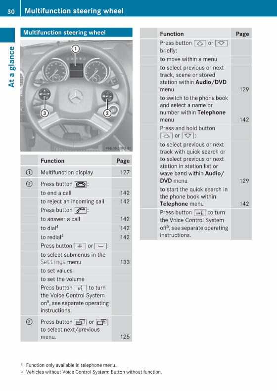
Multifunction steering wheel
Function Page
: Multifunction display 127
; Press button ~:to end a call 142to reject an incoming call 142Press button 6:to answer a call 142to dial4 142to redial4 142Press button W or X:to select submenus in theSettings menu 133to set valuesto set the volumePress button ? to turnthe Voice Control Systemon5, see separate operatinginstructions.
= Press button V or Uto select next/previousmenu. 125
Function PagePress button & or *briefly:to move within a menuto select previous or nexttrack, scene or storedstation within Audio/DVDmenu 129to switch to the phone bookand select a name ornumber within Telephonemenu 142Press and hold button& or *:to select previous or nexttrack with quick search orto select previous or nextstation in station list orwave band within Audio/DVD menu 129to start the quick search inthe phone book withinTelephone menu 142Press button A to turnthe Voice Control Systemoff5, see separate operatinginstructions.
4 Function only available in telephone menu.5 Vehicles without Voice Control System: Button without function.
30 Multifunction steering wheelAt
a g
lanc
e
X164_AKB; 5; 31, en-USd2ureepe, Version: 2.11.8.1
2009-09-11T12:30:16+02:00 - Seite 30
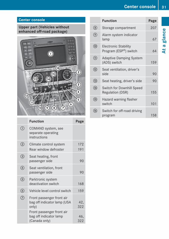
Center console
Upper part (Vehicles without enhanced off-road package)
Function Page
: COMAND system, seeseparate operatinginstructions
; Climate control system 172Rear window defroster 191
= Seat heating, frontpassenger side 90
? Seat ventilation, frontpassenger side 90
A Parktronic systemdeactivation switch 168
B Vehicle level control switch 159
C Front passenger front airbag off indicator lamp (USAonly)
42,322
Front passenger front airbag off indicator lamp(Canada only)
46,322
Function Page
D Storage compartment 207
E Alarm system indicatorlamp 67
F Electronic StabilityProgram (ESP®) switch 64
G Adaptive Damping System(ADS) switch 159
H Seat ventilation, driver’sside 90
I Seat heating, driver’s side 90
J Switch for Downhill SpeedRegulation (DSR) 155
K Hazard warning flasherswitch 101
L Switch for off-road drivingprogram 158
Center console 31
At a
gla
nce
X164_AKB; 5; 31, en-USd2ureepe, Version: 2.11.8.1
2009-09-11T12:30:16+02:00 - Seite 31
Z

Upper part (Vehicles with enhanced off-road package)
Function Page
: COMAND system, seeseparate operatinginstructions
; Climate control system 172Rear window defroster 191
= Seat heating, frontpassenger side 90
? Seat ventilation, frontpassenger side 90
A Rotary switch fordifferential locks 122
B Switch for LOW RANGEmode 120
C Switch for Downhill SpeedRegulation (DSR) 155
D Rotary switch for vehiclelevel control 159
E Alarm system indicatorlamp 67
Function Page
F Seat ventilation, driver’sside 90
G Seat heating, driver’s side 90
H Adaptive Damping System(ADS) switch 159
I Electronic StabilityProgram (ESP®) switch 64
J Parktronic systemdeactivation switch 168
K Hazard warning flasherswitch 101
L Front passenger front airbag off indicator lamp (USAonly)
42,322
Front passenger front airbag off indicator lamp(Canada only)
46,322
32 Center consoleAt
a g
lanc
e
X164_AKB; 5; 31, en-USd2ureepe, Version: 2.11.8.1
2009-09-11T12:30:16+02:00 - Seite 32

Lower part
Function Page
: Ashtray with storagecompartment 211Cigarette lighter 212
; Cup holder 209
= Front armrest storagecompartment 207
? Removable card/ticketholder 209
Overhead control panel
Function Page
: Left front reading lamp on/off 101
; Automatic interior lighting 101
= Rear interior lighting on/off 101
? Front interior lighting on/off 101
A Right reading lamp on/off 101
B Front right interior lamp 101
C Power tilt/sliding sunroofswitch 192
D SOS button (Tele Aidsystem) 216
E Interior rear view mirror 93
F Reading lamps 101
G Garage door opener 219
Overhead control panel 33
At a
gla
nce
X164_AKB; 5; 31, en-USd2ureepe, Version: 2.11.8.1
2009-09-11T12:30:16+02:00 - Seite 33
Z

Function Page
H Hands-free microphone forTele Aid (emergency callsystem), telephone andVoice Control System, seeseparate operatinginstructions
I Front left interior lamp 101
Door control panel
Function Page
: Inside door handle 74
; Central locking/unlockingswitch 75
= Exterior rear view mirroradjustment 94
? Selection buttons forexterior rear view mirroradjustment 94Power-folding exterior rearview mirrors 95
A Switches for opening/closing front and rear doorwindows 105
B Rear door window overrideswitch 60
C Hinged quarter windowswitch 105
D Remote tailgate switch,power tailgate 79
34 Door control panelAt
a g
lanc
e
X164_AKB; 5; 31, en-USd2ureepe, Version: 2.11.8.1
2009-09-11T12:30:16+02:00 - Seite 34

Vehicle equipment .............................. 36Occupant safety .................................. 36Panic alarm .......................................... 61Driving safety systems ....................... 61Anti-theft systems .............................. 66
35
Safe
ty a
nd s
ecur
ity
X164_AKB; 5; 31, en-USd2ureepe, Version: 2.11.8.1
2009-09-11T12:30:16+02:00 - Seite 35

Vehicle equipment
i This Operator’s Manual describes allfeatures, standard or optional, potentiallyavailable for your vehicle at the time ofpurchase. Please be aware that yourvehicle might not be equipped with allfeatures described in this manual.
Occupant safety
IntroductionIn this section you will learn the mostimportant facts about the restraint systemcomponents of the vehicle.The restraint systems are:RSeat beltsRChild restraintsRLower Anchors and Tethers for CHildren
(LATCH)Additional protection potential is provided by:RSupplemental Restraint System (SRS) with
- Air bags- Air bag control unit (with crash sensors)- Emergency Tensioning Device (ETD) for
seat belts- Seat belt force limiter
RNECK-PRO active front head restraintsRPreventive occupant safety (PRE-SAFE®)RAir bag system components with
- Front passenger front air bag offindicator lamp
- USA only: Front passenger seat withOccupant Classification System (OCS)
- Canada only: Front passenger seat withBabySmart™ air bag deactivation system
Although the systems are independent, theirprotective functions work in conjunction witheach other.
G Warning!Modifications to or work improperlyconducted on restraint system componentsor their wiring, as well as tampering withinterconnected electronic systems, can leadto the restraint systems no longer functioningas intended.Air bags or Emergency Tensioning Devices(ETDs), for example, could deployinadvertently or fail to deploy in accidentsalthough the deceleration threshold for airbag deployment is exceeded. Therefore,never modify the restraint systems. Do nottamper with electronic components or theirsoftware.
i See “Children in the vehicle”(Y page 55) for information onRinfants and children traveling with you in
the vehicleRrestraint systems for infants and children
SRS indicator lampThe SRS system conducts a self-test whenthe ignition is switched on and in regularintervals while the engine is running. Thisfacilitates detection of system malfunctions.The SRS indicator lamp + in theinstrument cluster comes on when theignition is switched on. It goes out no laterthan a few seconds after the engine has beenstarted.The SRS components are in operationalreadiness when the SRS indicator lamp+ is not lit while the engine is running.A malfunction in the system has beendetected if the SRS indicator lamp +Rfails to go out after approximately
4 seconds after the engine was startedRdoes not come on at allRcomes on after the engine was started or
while driving
36 Occupant safetySa
fety
and
sec
urity
X164_AKB; 5; 31, en-USd2ureepe, Version: 2.11.8.1
2009-09-11T12:30:16+02:00 - Seite 36

G Warning!The SRS self-check has detected amalfunction when the SRS indicator lamp+:Rdoes not come on at allRdoes not go out after 4 seconds after the
engine was startedRcomes on while driving
For your safety, we strongly recommend thatyou contact an authorized Mercedes-BenzCenter immediately to have the systemchecked. Otherwise the SRS may not beactivated when needed in an accident, whichcould result in serious or fatal injury. The SRSmight also deploy unexpectedly andunnecessarily which could also result in injuryas well.In addition, improper work on the SRS createsa risk of rendering the SRS inoperative orcausing unintended air bag deployment. Workon the SRS must therefore only be performedby qualified technicians. Contact anauthorized Mercedes-Benz Center.If it is necessary to modify an air bag systemto accommodate a person with disabilities,contact an authorized Mercedes-Benz Center.USA only: Call our Customer AssistanceCenter at 1-800-FOR-MERCedes(1-800-367-6372) for details.
Air bags
G Warning!Air bags are designed to reduce the potentialof injury and fatality in certainRfrontal impacts (front air bags and driver’s
side knee bag)Rside impacts (side impact air bags and
window curtain air bags)Rrollovers (window curtain air bags)
However, no system available today cancompletely eliminate injuries and fatalities.
Deployment of the air bags temporarilyreleases a small amount of dust from the airbags. This dust, however, is neither harmfulto your health, nor does it indicate a fire in thevehicle. The dust might cause sometemporary breathing difficulty for people withasthma or other breathing trouble. To avoidthis, you may wish to get out of the vehicle assoon as it is safe to do so. If you have anybreathing difficulty but cannot get out of thevehicle after the air bag inflates, then get freshair by opening a window or door.
G Warning!To reduce the risk of injury when the front airbags inflate, it is very important for the driverand front passenger to always be in a properlyseated position and to wear their respectiveseat belt.For maximum protection in the event of acollision always be in normal seated positionwith your back against the seat backrest.Fasten your seat belt and make sure it isproperly positioned on your body.Since the air bag inflates with considerablespeed and force, a proper seating positionand correct positioning of the hands on thesteering wheel will help to keep you at a safedistance from the air bag. Occupants who arenot wearing their seat belt, are not seatedproperly or are too close to the air bag can beseriously injured or killed by an air bag as itinflates with great force instantaneously:RSit with the seat belt properly fastened in a
position that is as upright as possible withyour back against the seat backrest.RMove the driver’s seat as far back as
possible, still permitting proper operationof vehicle controls. The distance from thecenter of the driver’s chest to the center ofthe air bag cover on the steering wheelmust be at least 10 inches (25 cm) or more.You should be able to accomplish this byadjusting the seat and steering wheel. If
Occupant safety 37
Safe
ty a
nd s
ecur
ity
X164_AKB; 5; 31, en-USd2ureepe, Version: 2.11.8.1
2009-09-11T12:30:16+02:00 - Seite 37
Z

you have any difficulties, please contact anauthorized Mercedes-Benz Center.RDo not lean your head or chest close to the
steering wheel or dashboard.RKeep hands on the outside of the steering
wheel rim. Placing hands and arms insidethe rim can increase the risk and potentialseverity of hand/arm injury when the driverfront air bag inflates.RAdjust the front passenger seat as far as
possible rearward from the dashboardwhen the seat is occupied.ROccupants, especially children, should
never place their bodies or lean their headsin the area of the door where the sideimpact air bag inflates. This could result inserious injuries or death should the sideimpact air bag be deployed. Always sit asupright as possible, wear the seat beltproperly and use an appropriately sizedinfant restraint, toddler restraint, orbooster seat recommended for the size andweight of the child.RCanada only: Children 12 years old and
under must never ride in the front seat,except in a Mercedes-Benz authorizedBabySmart™ compatible child seat, whichoperates with the BabySmart™ air bagdeactivation system installed in the vehicleto deactivate the front passenger front airbag when it is installed properly. Otherwisethey will be struck by the air bag when itinflates in a crash. If this happens, seriousor fatal injury will result.
Failure to follow these instructions can resultin severe injuries to you or other occupants.If you sell your vehicle, it is important that youmake the buyer aware of this safetyinformation. Be sure to give the buyer thisOperator’s Manual.
G Warning!Accident research shows that the safest placefor children in an automobile is in a rear seat.
There is a possibility for a side impact air bag-related injury if occupants, especiallychildren, are not properly seated or restrainedwhen next to a side impact air bag whichneeds to deploy rapidly in a side impact inorder to do its job.To help avoid the possibility of injury, pleasefollow these guidelines:
(1) Always sit as upright as possible,wear the seat belt properly, and forchildren 12 years old and under,use an appropriately sized infantrestraint, toddler restraint, orbooster seat recommended for thesize and weight of the child.
(2) Always wear seat belts properly.
Air bags are designed to deploy only in certainRfrontal impacts (front air bags and driver’s
side knee bag)Rside impacts (side impact and window
curtain air bags) if the system determinesthe need for air bag deploymentRrollovers (window curtain air bags)Only in the event of such a situation will theyprovide their supplemental protection.The driver and passengers should alwayswear their seat belts. Otherwise it is notpossible for the air bags to provide theirsupplemental protection.In case of other types of impacts and impactsbelow air bag deployment thresholds, airbags will not deploy. The driver andpassengers will then be protected to theextent possible by a properly fastened seatbelt. A properly fastened seat belt is alsoneeded to provide the best possibleprotection in a rollover.Air bags are not a substitute for seat belts.Always wear your seat belt, regardless ofwhether or not your vehicle is equipped withair bags.It is important to your safety and that of yourpassengers to have deployed air bags
38 Occupant safetySa
fety
and
sec
urity
X164_AKB; 5; 31, en-USd2ureepe, Version: 2.11.8.1
2009-09-11T12:30:16+02:00 - Seite 38

replaced and to have any malfunctioning airbags repaired. This will help to make sure theair bags will continue to provide supplementalcrash protection for occupants.
Safety guidelines for the seat belt, Emergency Tensioning Device (ETD) and air bag
G Warning!RDamaged seat belts or seat belts that have
been subjected to stress in an accidentmust be replaced. Their anchoring pointsmust also be checked. Only use seat beltsinstalled or supplied by an authorizedMercedes-Benz Center.RAir bags and pyrotechnic Emergency
Tensioning Devices (ETDs) containperchlorate material, which may requirespecial handling and regard for theenvironment. Check with your localgovernment’s disposal guidelines.California residents, seewww.dtsc.ca.gov/HazardousWaste/Perchlorate/index.cfm.RAir bags and ETDs are designed to function
on a one-time-only basis. An air bag or ETDthat has deployed must be replaced. PRE-SAFE® has electrically operated reversiblepre-tensioners in addition to thepyrotechnic ETDs.RDo not pass seat belts over sharp edges.
They could tear.RDo not make any modification that could
change the effectiveness of the seat belts.RDo not bleach or dye seat belts as this may
severely weaken them. In a crash they maynot be able to provide adequate protection.RNo modifications of any kind may be made
to any components or wiring of the SRS.RDo no change or remove any component or
part of the SRS.RDo not install additional trim material, seat
covers, badges, etc. over the steering
wheel hub, front passenger front air bagcover, outboard sides of the seatbackrests, door trim panels, or door frametrims.RDo not install additional electrical/
electronic equipment on or near SRScomponents and wiring.RKeep area between air bags and occupants
free of objects (e.g. packages, purses,umbrellas, etc.).RDo not hang items such as coat hangers
from the coat hooks or handles over thedoor. These items may be thrown around inthe vehicle and cause head and otherinjuries when the window curtain air bag isdeployed.RAir bag system components will be hot after
an air bag has inflated. Do not touch them.RNever place your feet on the instrument
panel, dashboard, or on the seat. Alwayskeep both feet on the floor in front of theseat.RImproper repair work on the SRS creates a
risk of rendering the SRS inoperative orcausing unintended air bag deployment.Work on the SRS must therefore only beperformed by qualified technicians.Contact an authorized Mercedes-BenzCenter.RFor your protection and the protection of
others, when scrapping the air bag unit orETD, our safety instructions must befollowed. These instructions are availablefrom any authorized Mercedes-BenzCenter.RGiven the considerable deployment speed,
required inflation volume, and the materialof the air bags, there is the possibility ofabrasions or other, potentially more seriousinjuries resulting from air bag deployment.
If you sell your vehicle, we stronglyrecommend that you inform the subsequentowner that the vehicle is equipped with SRS.
Occupant safety 39
Safe
ty a
nd s
ecur
ity
X164_AKB; 5; 31, en-USd2ureepe, Version: 2.11.8.1
2009-09-11T12:30:16+02:00 - Seite 39
Z

Also refer them to the applicable section inthe Operator’s Manual.
Front air bags
G Observe Safety notes, see page 37.
Driver’s front air bag : and front passengerfront air bag ; are designed to provideincreased protection for the driver and frontpassenger against the risk of injuries to thehead and thorax.Driver and front passenger front air bag anddriver’s side knee bag are deployedRin the event of certain frontal impactsRif the system determines that air bag
deployment can offer additional protectionto that provided by the seat beltRdepending on whether the respective seat
belt is in useRindependently of the side impact air bags
and/or the window curtain air bagsThe front air bags in this vehicle have beendesigned to inflate in two stages. This allowsthe air bags to have different rates of inflation.The rate of inflation is based on the vehicledeceleration rate as assessed by the air bagcontrol unit.Vehicles with OCS, USA only: The frontpassenger front air bag deployment isadditionally influenced by the passenger’sweight category as identified by the OccupantClassification System (OCS) (Y page 42).Vehicles with OCS, USA only: The lighter thefront passenger-side occupant, the higher the
vehicle deceleration rate required for secondstage inflation of the front passenger front airbag.The air bags will not deploy in impacts whichdo not exceed the system’s presetdeployment thresholds. You will then beprotected by the fastened seat belts.The front air bags will not deploy in the eventof a rollover unless the vehicle’s rate oflongitudinal deceleration or accelerationexceeds the preset deployment threshold forthe front air bags.The front passenger front air bag will only bedeployed ifRvehicles with OCS, USA only: the system,
based on OCS weight sensor readings,detects that the front passenger seat isoccupiedRthe 42 indicator lamp in the
center console is not lit(USA only: (Y page 42),Canada only: (Y page 46))Rthe impact exceeds a preset deployment
threshold
! Vehicles with BabySmart™ air bagdeactivation system (Canada only): Do notplace objects heavier than 20 lb (9 kg) onthe front passenger seat. This could causethe front or side impact air bag on the frontpassenger side to deploy in a crash whichexceeds the system’s deploymentthreshold.
Knee bag Knee bag = is designed to provide increasedprotection for the driver against the risk ofinjuries to the knees, thighs and lower legs.Knee bag = is located on the driver sidelower instrument panel. It is designed tooperate together with the driver front air bagin certain frontal impacts if the systemdetermines that air bag deployment can offeradditional protection to that provided by theseat belt. Knee bag = operates best in
40 Occupant safetySa
fety
and
sec
urity
X164_AKB; 5; 31, en-USd2ureepe, Version: 2.11.8.1
2009-09-11T12:30:16+02:00 - Seite 40

conjunction with a properly positioned andfastened seat belt.
Side impact air bags
G Observe Safety notes, see page 37.
G Warning!The pressure sensors for side impact air bagcontrol are located in the doors. Do notmodify any components of the doors or doortrim panels including, for example, theaddition of door speakers.Improper repair work on the doors or themodification or addition of components to thedoors create a risk of rendering the sideimpact air bags inoperative or causingunintended air bag deployment. Work on thedoors must therefore only be performed byqualified technicians. Contact an authorizedMercedes-Benz Center.
Front side impact air bags : and rear sideimpact air bags ; are designed to provideincreased protection for the thorax but notthe head, neck and arms.The side impact air bags are deployedRon the impacted side of the vehicleRin instances with a high rate of lateral
vehicle deceleration or accelerationRregardless of whether the seat belts on the
impacted side of the vehicle are in useRindependently of the front air bagsRindependently of the ETDs
Vehicles with OCS (USA only): The frontpassenger side impact air bag will not deployif the OCS senses that the front passengerseat is empty and the front passenger seatbelt is not fastened. With the front passengerseat empty and the seat belt fastened, thefront passenger side impact air bag willdeploy independently of the empty seat.Whether a seat belt is recognized as fasteneddepends on whether or not the latch plate isproperly inserted into the buckle.The side impact air bags are not deployed inside impacts which do not exceed thesystem’s deployment threshold.The side impact air bags will not deploy in theevent of a rollover unless the vehicle’s rate oflateral deceleration or acceleration exceedsthe preset deployment threshold for the sideimpact air bags.
! Vehicles with BabySmart™ air bagdeactivation system (Canada only): Do notplace objects heavier than 20 lb (9 kg) onthe front passenger seat. This could causethe front or side impact air bag on the frontpassenger side to deploy in a crash whichexceeds the system’s deploymentthreshold.
G Warning!Only use seat covers which have been testedand approved by Mercedes-Benz for yourvehicle model. Using other seat covers mayinterfere with or prevent the deployment ofthe side impact air bags. Contact anauthorized Mercedes-Benz Center foravailability.
Occupant safety 41
Safe
ty a
nd s
ecur
ity
X164_AKB; 5; 31, en-USd2ureepe, Version: 2.11.8.1
2009-09-11T12:30:16+02:00 - Seite 41
Z

Window curtain air bags
G Observe Safety notes, see page 37.
Window curtain air bags : are designed toprovide increased protection for the head butnot the chest or arms.Window curtain air bags : are deployedRon the impacted side of the vehicleRin instances with a high rate of lateral
vehicle deceleration or accelerationRindependently of the front air bagsRregardless of whether the front passenger
seat is occupiedRregardless of whether the seat belt on the
impacted side of the vehicle is in useRin certain vehicle rollovers, if the system
determines that air bag deployment canoffer additional protection to that providedby the seat belt
Window curtain air bags : are not deployedin impacts which do not exceed the system’sdeployment threshold.Window curtain air bags : deploy in the areaindicated by the arrows.
Occupant Classification SystemThe Occupant Classification System (OCS) isstandard equipment in USA.The OCS activates or deactivates the frontpassenger front air bag automatically. Therespective status is based on the classifiedoccupant weight category determined by
weight sensor readings from the frontpassenger seat.The system does not deactivateRthe front passenger side impact air bagRthe window curtain air bagRthe Emergency Tensioning Devices (ETDs)To be classified correctly, the front passengermust sitRwith the seat belt properly fastenedRin a position that is as upright as possible
with the back against the seat backrestRwith the feet on the floorIf the occupant’s weight is transferred toanother object in the vehicle (e.g. by leaningon armrests), the OCS may not be able toproperly approximate the occupant’s weightcategory.Furthermore, the occupant weight mayappear to increase or decrease due to thefollowing:Robjects hanging on the seatRobjects lodged underneath the seatRobjects stuffed between the seat and
middle consoleRobjects stuffed between the seat and doorRother passengers pushing on the seatRobjects applying pressure to the back of
the seatAlways make sure the seat has clearancein all directions at all times.
If your seat, including the trim cover andcushion, needs to be serviced in any way, takethe vehicle to an authorized Mercedes-BenzCenter.Only seat accessories approved byMercedes-Benz may be used.Both the driver and the front passengershould always use the 42indicator lamp as an indication of whether ornot the front passenger is properlypositioned.
42 Occupant safetySa
fety
and
sec
urity
X164_AKB; 5; 31, en-USd2ureepe, Version: 2.11.8.1
2009-09-11T12:30:16+02:00 - Seite 42

G Warning!If the 42 indicator lampilluminates when an adult or someone largerthan a small individual is in the frontpassenger seat, have the front passengerreposition himself or herself in the seat untilthe 42 indicator lamp goes out,or check whether objects are caught under oraround the seat.In the event of a collision, the air bag controlunit will not allow front passenger front air bagdeployment when the OCS has classified thefront passenger seat occupant as weightingas much as or less than a typical 12-month-old child in a standard child restraint or if thefront passenger seat is classified as beingempty.When the OCS senses that the frontpassenger seat occupant is classified asbeing up to or less than the weight of a typical12-month-old child in a standard childrestraint, the 42 indicator lampwill illuminate when the engine is started andremain illuminated, indicating that the frontpassenger front air bag is deactivated.When the OCS senses that the frontpassenger seat is classified as being empty,the 42 indicator lamp willilluminate when the engine is started andremain illuminated, indicating that the frontpassenger front air bag is deactivated.When the OCS senses that the frontpassenger seat occupant is classified asbeing heavier than the weight of a typical12-month-old child seated in a standard childrestraint or as being a small individual (suchas a young teenager or a small adult), the42 indicator lamp will illuminatefor approximately 6 seconds when the engineis started and then, depending on occupantweight sensor readings from the seat, remainilluminated or go out. With the42 indicator lamp illuminated,the front passenger front air bag isdeactivated. With the 42
indicator lamp out, the front passenger frontair bag is activated.When the OCS senses that the frontpassenger seat occupant is classified as anadult or someone larger than a smallindividual, the 42 indicator lampwill illuminate for approximately 6 secondswhen the engine is started and then goes out,indicating that the front passenger front airbag is activated.If the 42 indicator lamp isilluminated, the front passenger front air bagis deactivated and will not be deployed.If the 42 indicator lamp is notilluminated, the front passenger front air bagis activated and will be deployedRin the event of certain frontal impactsRif impact exceeds a preset deployment
thresholdRindependently of the side impact air bags
If the front passenger front air bag isdeployed, the rate of inflation will beinfluenced byRthe rate of relevant vehicle deceleration as
assessed by the air bag control unitRthe front passenger’s weight category as
identified by the OCS
For more information on air bag displaymessages in the multifunction display, see(Y page 291).
G Warning!According to accident statistics, children aresafer when properly restrained in the rearseating positions than in the front seatingposition. Thus, we strongly recommend thatchildren be placed in the rear seats wheneverpossible. Regardless of seating position,children 12 years old and under must beseated and properly secured in an appropriateinfant restraint, toddler restraint, or boosterseat recommended for the size and weight ofthe child.
Occupant safety 43
Safe
ty a
nd s
ecur
ity
X164_AKB; 5; 31, en-USd2ureepe, Version: 2.11.8.1
2009-09-11T12:30:16+02:00 - Seite 43
Z

The infant or child restraint must be properlysecured with the vehicle’s seat belt, the seatbelt and top tether strap, or lower anchors andtop tether strap, fully in accordance with thechild seat manufacturer’s instructions.Occupants, especially children, should alwayssit as upright as possible, wear the seat beltproperly and use an appropriately sized infantrestraint, toddler restraint, or booster seatrecommended for the size and weight of thechild.Children can be killed or seriously injured byan inflating air bag. Note the followingimportant information when circumstancesrequire you to place a child in the frontpassenger seat:RYour vehicle is equipped with air bag
technology designed to deactivate the frontpassenger front air bag in your vehiclewhen the system senses the weight of atypical 12-month-old child or less alongwith the weight of a standard appropriatechild restraint on the front passenger seat.RA child in a rear-facing child restraint on the
front passenger seat will be seriouslyinjured or even killed if the front passengerfront air bag inflates in a collision whichcould occur under some circumstances,even with the air bag technology installedin your vehicle. The only means tocompletely eliminate this risk is to neverplace a child in a rear-facing child restraintin the front seat. We therefore stronglyrecommend that you always place a childin a rear-facing child restraint in a backseat.RIf you must install a rear-facing child
restraint on the front passenger seatbecause circumstances require you to doso, make sure the 42indicator lamp is illuminated, indicatingthat the front passenger front air bag isdeactivated. Should the 42indicator lamp not illuminate or go out whilethe restraint is installed, please checkinstallation. Periodically check the
42 indicator lamp whiledriving to make sure the 42indicator lamp is illuminated. If the42 indicator lamp goes out orremains out, do not transport a child on thefront passenger seat until the system hasbeen repaired.A child in a rear-facing child restraint on thefront passenger seat will be seriouslyinjured or even killed if the front passengerfront air bag inflates.RIf you have to place a child in a forward-
facing child restraint on the front passengerseat, move the seat as far back as possible,use the proper child restraintrecommended for the age, size and weightof the child, and secure child restraint withthe vehicle’s seat belt according to the childseat manufacturer’s instructions. Forchildren larger than the typical 12-month-old child, the front passenger front air bagmay or may not be activated.
Deployment of the driver front air bag doesnot mean that the front passenger front airbag also should have deployed.The OCS may have determinedRthat the seat was empty or occupied by the
weight up to or less than that of a typical12-month-old child seated in a standardchild restraint – both of which are instanceswhere the system suppresses deploymentof the front passenger front air bag eventhough the impact met the criteria and wasof sufficient severity to deploy the driverfront air bagRthat the seat was occupied by a small
individual (such as a young teenager or asmall adult) or a child who weighs morethan the weight of a typical 12-month-oldchild in a standard child restraint – both ofwhich are instances where the system maysuppress deployment of the frontpassenger front air bag even though theimpact met the criteria and was of
44 Occupant safetySa
fety
and
sec
urity
X164_AKB; 5; 31, en-USd2ureepe, Version: 2.11.8.1
2009-09-11T12:30:16+02:00 - Seite 44

sufficient severity to deploy the driver frontair bag
42 indicator lamp : will beilluminated, except with the SmartKeyremoved from the starter switch or with thestarter switch in position 0.
G Warning!If the red SRS indicator lamp + in theinstrument cluster and the 42indicator lamp are lit at the same time, thereis a malfunction in the OCS. The frontpassenger front air bag will be deactivated inthis case. Have the system checked byqualified technicians as soon as possible.Contact an authorized Mercedes-BenzCenter.Only have the seat repaired or replaced at anauthorized Mercedes-Benz Center.In order to ensure proper operation of the airbag system and OCS:RDo not place more than 4.4 lb (2 kg) into
the parcel net on the back of the frontpassenger seat. Otherwise, the OCS maynot be able to properly approximate theoccupant weight category.RDo not place objects under and/or around
the front passenger seat.RDo not hang anything from or attach any
items to the seats.RDo not stuff objects such as books between
the front passenger seat and the centerconsole or front passenger door.
RDo not move the front passenger seatbackwards against stiff objects.RSit with the seat belt properly fastened in a
position that is as upright as possible withyour back against the seat backrest.RWhile seated, an occupant should not
position him/herself in such a way as tocause the occupant’s weight to be liftedfrom the seat bottom as this may result inthe OCS being unable to correctlyapproximate the occupant’s weightcategory.RRead and observe all warnings in this
chapter.
OCS Self-test After turning the SmartKey in the starterswitch to position 1 or 2 or pressing theKEYLESS-GO start/stop button once ortwice, the 42 indicator lampilluminates. If an adult occupant is properlysitting on the front passenger seat and thesystem classifies the occupant as an adult,the 42 indicator lamp willilluminate and go out after approximately6 seconds.If the seat is not occupied and the systemclassifies the front passenger seat as beingempty, the 42 indicator lampwill illuminate and not go out.
G Warning!If the 42 indicator lamp does notilluminate, the system is not functioning. Youmust contact an authorized Mercedes-BenzCenter before seating any child on the frontpassenger seat.
For more information, see the “Practicalhints” section (Y page 322).
G Warning!Never place anything between seat cushionand child seat (e.g. pillow), since it reducesthe effectiveness of the OCS. The bottom andback of the child seat must make full contact
Occupant safety 45
Safe
ty a
nd s
ecur
ity
X164_AKB; 5; 31, en-USd2ureepe, Version: 2.11.8.1
2009-09-11T12:30:16+02:00 - Seite 45
Z

with the passenger seat cushion andbackrest.If necessary, adjust the tilt of the passengerseat backrest.An incorrectly mounted child seat could causeinjuries to the child in case of an accident,instead of increasing protection for the child.Follow the manufacturer’s instructions forinstallation of child seats.
BabySmart™ air bag deactivation system
The BabySmart™ air bag deactivation systemis standard equipment in Canada.
G Warning!According to accident statistics, children aresafer when properly restrained in the rearseating positions than in the front seatingposition. Thus, we strongly recommend thatchildren be placed in the rear seats wheneverpossible. Regardless of seating position,children 12 years old and under must beseated and properly secured in an appropriateinfant restraint, toddler restraint, or boosterseat recommended for the size and weight ofthe child.The infant or child restraint must be properlysecured with the vehicle’s seat belt, the seatbelt and top tether strap, or lower anchors andtop tether strap, fully in accordance with thechild seat manufacturer’s instructions.Occupants, especially children, should alwayssit as upright as possible, wear the seat beltproperly and use an appropriately sized infantrestraint, toddler restraint, or booster seatrecommended for the size and weight of thechild.
Children can be killed or seriously injured byan inflating air bag. Note the followingimportant information when circumstancesrequire you to place a child in the frontpassenger seat:RChildren 12 years old and under must never
ride in the front seat, except in a Mercedes-Benz authorized BabySmart™ compatiblechild seat, which operates with theBabySmart™ system installed in the vehicleto deactivate the front passenger front airbag when it is installed properly. Otherwisethey will be struck by the air bag when itinflates in a crash. If this happens, seriousor fatal injury will result.RA child in a rear-facing child restraint on the
front passenger seat will be seriouslyinjured or even killed if the front passengerfront air bag inflates in a collision whichcould occur under some circumstances,even with the air bag technology installedin your vehicle. The only means tocompletely eliminate this risk is to neverplace a child in a rear-facing child restraintin the front seat. We therefore stronglyrecommend that you always place a childin a rear-facing child restraint in a backseat.RIf you must install a BabySmart™
compatible rear-facing child restraint onthe front passenger seat becausecircumstances require you to do so, makesure the 42 indicator lamp isilluminated, indicating that the frontpassenger front air bag is deactivated.Should the 42 indicator lampnot illuminate or go out while the restraintis installed, please check installation.Periodically check the 42indicator lamp while driving to make surethe 42 indicator lamp isilluminated. If the 42 indicatorlamp goes out or remains out, do nottransport a child on the front passengerseat until the system has been repaired.
46 Occupant safetySa
fety
and
sec
urity
X164_AKB; 5; 31, en-USd2ureepe, Version: 2.11.8.1
2009-09-11T12:30:16+02:00 - Seite 46

A child in a rear-facing child restraint on thefront passenger seat will be seriouslyinjured or even killed if the front passengerfront air bag inflates.RIf you have to place a child in a forward-
facing child restraint on the front passengerseat, move the seat as far back as possible,use the proper child restraintrecommended for the age, size and weightof the child, and secure child restraint withthe vehicle’s seat belt according to the childseat manufacturer’s instructions.
G Warning!When using a BabySmart™ compatible childseat on the front passenger seat, the frontpassenger front air bag will not deploy only ifthe 42 indicator lamp remainsilluminated.Please be sure to check the 42indicator lamp every time you use aBabySmart™ compatible child seat on thefront passenger seat. Should the42 indicator lamp go out whilethe restraint is installed, please checkinstallation. If the 42 indicatorlamp remains out, do not use theBabySmart™ restraint to transport a child onthe front passenger seat until the system hasbeen repaired.
Special BabySmart™ compatible child seats,designed for use with the Mercedes-Benzsystem, are required for use with theBabySmart™ air bag deactivation system.
Please contact an authorized Mercedes-BenzCenter for information on availability. Withthe special child seat installed properly, thefront passenger front air bag will not deploy.The 42 indicator lamp : will beilluminated, except with the SmartKeyremoved from the starter switch or with thestarter switch in position 0.The system does not deactivateRthe side impact air bagRthe window curtain air bagRthe Emergency Tensioning Device (ETD)
Self-test BabySmart™ without special child seat installed After turning the SmartKey in the starterswitch to position 1 or 2 or pressing theKEYLESS-GO start/stop button once ortwice, the 42 indicator lampcomes on for approximately 6 seconds andthen goes out.If the 42 indicator lamp shouldnot come on or is continuously lit, the systemis not functioning. You must see anauthorized Mercedes-Benz Center beforeseating any child on the front passenger seat.More information can be found in the“Practical hints” section (Y page 322).
G Warning!Do not place powered-on laptops, mobilephones, electronic tags such as those used inski passes and like electronic devices on thefront passenger seat. Signals from suchdevices may interfere with the BabySmart™air bag deactivation system. Such signalinterference may cause the 42indicator lamp not to come on during self-test.The SRS indicator lamp + and/or the42 indicator lamp could becontinuously lit, indicating that the system isnot functioning. The front passenger front airbag could deploy inadvertently or fail todeploy in an accident.
Occupant safety 47
Safe
ty a
nd s
ecur
ity
X164_AKB; 5; 31, en-USd2ureepe, Version: 2.11.8.1
2009-09-11T12:30:16+02:00 - Seite 47
Z

G Warning!The BabySmart™ air bag deactivation systemwill ONLY work with a special child seatdesigned to operate with it. It will not workwith child seats which are not BabySmart™compatible.Never place anything between seat cushionand child seat (e.g. pillow), since it reducesthe effectiveness off the BabySmart™ air bagdeactivation system. The bottom of the childseat must make full contact with the frontpassenger seat cushion. An incorrectlymounted child seat could cause injuries to thechild in case of an accident, instead ofprotecting the child.Follow the manufacturer’s instructions forinstallation of special child seats.
Seat belts
Safety notesThe use of seat belts and infant and childrestraint systems is required by law in all 50states, the District of Columbia, the U.S.territories and all Canadian provinces.Even where this is not the case, all vehicleoccupants should have their seat beltsfastened whenever the vehicle is in motion.For information on infants and childrentraveling with you in the vehicle and restraintsystems for infants and children, see“Children in the vehicle” (Y page 55).
G Warning!Always fasten your seat belt before driving off.Always make sure all of your passengers areproperly restrained. You and your passengersshould always wear seat belts.Failure to wear and properly fasten andposition your seat belt greatly increases yourrisk of injuries and their likely severity in anaccident.If you are ever in an accident, your injuries canbe considerably more severe without your
seat belt properly buckled. Without your seatbelt buckled, you are much more likely to hitthe interior of the vehicle or be ejected fromit. You can be seriously injured or killed.In the same crash, the possibility of injury ordeath is lessened if you are properly wearingyour seat belt. The air bags can only protectas intended if the occupants are properlywearing their seat belts.
G Warning!Never ride in a moving vehicle with the seatbackrest in an excessively reclined position asthis can be dangerous. You could slide underthe seat belt in a collision. If you slide underit, the seat belt would apply force at theabdomen or neck. That could cause seriousor even fatal injuries. The seat backrest andseat belt provide the best restraint when thewearer is in a position that is as upright aspossible and the seat belt is properlypositioned on the body.
G Warning!Never let more people ride in the vehicle thanthere are seat belts available. Make sureeveryone riding in the vehicle is correctlyrestrained with a separate seat belt. Neveruse a seat belt for more than one person at atime.
G Warning!Damaged seat belts or seat belts that havebeen subjected to stress in an accident mustbe replaced. Also, the seat belt anchoringpoints must be checked.Only use seat belts which have been approvedby Mercedes-Benz.Do not make any modifications to the seatbelts. This can lead to unintended activationof the ETDs or to their failure to activate whennecessary.Do not bleach or dye seat belts as this mayseverely weaken them. In a crash they maynot be able to provide adequate protection.
48 Occupant safetySa
fety
and
sec
urity
X164_AKB; 5; 31, en-USd2ureepe, Version: 2.11.8.1
2009-09-11T12:30:16+02:00 - Seite 48

Have all work carried out only by qualifiedtechnicians. Contact an authorizedMercedes-Benz Center.
Proper use of seat belts
G Warning!USE SEAT BELTS PROPERLYRSeat belts can only protect when used
properly. Never wear seat belts in any otherway than as described in this section, asthat could result in serious injuries in caseof an accident.REach occupant should wear their seat belt
at all times, because seat belts help reducethe likelihood of and potential severity ofinjuries in accidents, including rollovers.The integrated restraint system includesSRS (driver front air bag, driver side kneebag, front passenger front air bag, sideimpact air bags, window curtain air bags fordoor windows), Emergency TensioningDevices (ETDs), seat belt force limiters, andfront seat knee bolsters.The system is designed to enhance theprotection offered to properly beltedoccupants in certain frontal (front air bags,driver side knee bag and ETDs) and side(side impact air bags, window curtain airbags, and ETDs) impacts which exceedpreset deployment thresholds and incertain rollovers (window curtain air bagsand ETDs).RNever wear the shoulder belt under your
arm, against your neck or off your shoulder.In a frontal crash, your body would movetoo far forward. That would increase thechance of head and neck injuries. The seatbelt would also apply too much force to theribs or abdomen, which could severelyinjure internal organs such as your liver orspleen.Adjust the seat belt so that the shouldersection is located as close as possible tothe middle of the shoulder. It should not
touch the neck. Never pass the shoulderportion of the seat belt under your arm. Forthis purpose, you can adjust the height ofthe seat belt outlet.RPosition the lap belt as low as possible on
your hips and not across the abdomen. Ifthe lap belt is positioned across yourabdomen, it could cause serious injuries ina crash.RNever wear seat belts over rigid or
breakable objects in or on your clothing,such as eyeglasses, pens, keys etc., asthese might cause injuries.RMake sure the seat belt is always fitted
snugly. Take special care of this whenwearing loose clothing.RNever use a seat belt for more than one
person at a time. Do not fasten a seat beltaround a person and another person orother objects at the same time.RSeat belts should not be worn twisted. In a
crash, you would not have the full width ofthe seat belt to distribute impact forces.The twisted seat belt against your bodycould cause injuries.RPregnant women should also always use a
lap/shoulder belt. The lap belt portionshould be positioned as low as possible onthe hips to avoid any possible pressure onthe abdomen.RPlace the seat backrest in a position that is
as upright as possible.RCheck your seat belt during travel to make
sure it is properly positioned.RNever place your feet on the instrument
panel, dashboard, or on the seat. Alwayskeep both feet on the floor in front of theseat.RWhen using a seat belt to secure infant
restraints, toddler restraints, or children inbooster seats, always follow the child seatmanufacturer’s instructions.
Occupant safety 49
Safe
ty a
nd s
ecur
ity
X164_AKB; 5; 31, en-USd2ureepe, Version: 2.11.8.1
2009-09-11T12:30:16+02:00 - Seite 49
Z

G Warning!Do not pass seat belts over sharp edges. Theycould tear.Do not allow the seat belt to get caught in thedoor or in the seat adjustment mechanism.This could damage the seat belt.Never attempt to make modifications to seatbelts. This could impair the effectiveness ofthe seat belts.
Fastening the seat belts
G Warning!According to accident statistics, children aresafer when properly restrained in the rearseating positions than in the front seatingposition. Thus, we strongly recommend thatchildren be placed in the rear seats wheneverpossible. Regardless of seating position,children 12 years old and under must beseated and properly secured in anappropriately sized infant restraint, toddlerrestraint, or booster seat recommended forthe size and weight of the child. For additionalinformation, see “Children in the vehicle”.A child’s risk of serious or fatal injuries issignificantly increased if the child restraintsare not properly secured in the vehicle and/or the child is not properly secured in the childrestraint.
G Warning!Vehicles with BabySmart™ air bagdeactivation system, Canada only: Children12 years old and under must never ride in thefront seat, except in a Mercedes-Benzauthorized BabySmart™ compatible childseat, which operates with the BabySmart™system installed in the vehicle to deactivatethe front passenger front air bag when it isinstalled properly. Otherwise they will bestruck by the air bag when it inflates in acrash. If this happens, serious or fatal injurywill result.
X With a smooth motion, pull the seat belt outof seat belt outlet :.
X Place the shoulder portion of the seat beltacross the top of your shoulder and the lapportion across your hips.
X Push latch plate ; into buckle = until itclicks.Seat belt adjustment function: The seatbelts on both front seats adjust to theupper body automatically as necessary(Y page 51).
X If necessary, adjust the seat belt to thecorrect height (Y page 51).
X If necessary, tighten the lap portion to asnug fit by pulling shoulder portion up.
All lap/shoulder belts except the driver’s seatbelt have special seat belt retractors tosecure child restraints properly. For moreinformation on special seat belt retractors,see “Infant and child restraint system”(Y page 56).To release the seat belt with seat belt releasebutton ?, see (Y page 51).
50 Occupant safetySa
fety
and
sec
urity
X164_AKB; 5; 31, en-USd2ureepe, Version: 2.11.8.1
2009-09-11T12:30:16+02:00 - Seite 50

Seat belt outlet height adjustment
X Raising: Slide the seat belt outlet heightadjuster upward.The seat belt outlet height adjusterengages in different positions.
X Lowering: Press and hold releasebutton :.
X Slide the seat belt outlet height adjusterdownward.
X Release button : and make sure the seatbelt outlet height adjuster engages intoplace.
Seat belt adjustment functionThe seat belt adjustment function adjusts theseat belts on both front seats to the upperbody of the respective vehicle occupant. Theseat belt will be pulled slightly tighter for thatpurpose whenRyou engage the latch plate into the buckle
and then turn the SmartKey in the starterswitch to position 2Rthe SmartKey in the starter switch is in
position 2 and you then engage the latchplate in the buckle
The seat belt adjustment function takes placewith a certain amount of retracting forcewhen the system senses slack between thevehicle occupant and the seat belt. Do notretain the seat belt during this procedure. Youcan activate or deactivate the seat beltadjustment function via the control system(Y page 139).
Releasing the seat beltsX Press seat belt release button ?
(Y page 50).Allow the retractor to completely rewindthe seat belt by guiding latch plate ;(Y page 50).
! Make sure the seat belt retractscompletely. Otherwise the seat belt and/orlatch plate could get caught or pinched inthe door or in the seat mechanism. This candamage the seat belt and impair itseffectiveness, and/or cause damage to thedoor and/or door trim panel. Such damageis not covered by the Mercedes-BenzLimited Warranty.Damaged seat belts must be replaced.Contact an authorized Mercedes-BenzCenter.
Enhanced seat belt reminder systemWhen the engine is started, the seat belttelltale 7 will always illuminate for6 seconds to remind you and your passengersto fasten your seat belts.If the driver’s seat belt is not fastened whenthe engine is started, an additional warningchime will sound. The warning chime goes outafter approximately 6 seconds or once thedriver’s seat belt is fastened.If after these 6 seconds the driver’s or thefront passenger’s seat belt (with the frontpassenger seat occupied) is not fastened withfront doors closed,Rthe seat belt telltale 7 remains
illuminated for as long as either the driver’sor front passenger’s seat belt is notfastened.Rand if the vehicle speed once exceeds
15 mph (25 km/h), the seat belt telltale7 starts flashing and a warning chimesounds with increasing intensity for amaximum of 60 seconds or until thedriver’s and front passenger’s seat belt arefastened.
Occupant safety 51
Safe
ty a
nd s
ecur
ity
X164_AKB; 5; 31, en-USd2ureepe, Version: 2.11.8.1
2009-09-11T12:30:16+02:00 - Seite 51
Z

If you and/or your passenger release theseat belt during driving, the seat belttelltale 7 starts flashing and thewarning chime sounds as described before.If the driver’s or the front passenger’s seatbelt remains unfastened after 60 seconds,the warning chime stops sounding, the seatbelt telltale 7 stops flashing butcontinues to be illuminated.After a vehicle standstill, the warning chimeis reactivated and the seat belt telltale7 is flashing again if the vehicle speedonce exceeds 15 mph (25 km/h).
The seat belt telltale 7 will only go out ifboth the driver’s and the front passenger’sseat belt (with the front passenger seatoccupied) are fastened, or the vehicle isstanding still and a front door is opened.For more information, see “Practical hints”(Y page 317).
Emergency Tensioning Device (ETD), seat belt force limiterThe seat belts for the front seats and secondrow outer seats are equipped with ETDs andseat belt force limiters. The seat belts for thethird-row seats are equipped with ETDs.The ETDs are designed to activate in thefollowing cases:Rin frontal or rear-end impacts exceeding
the system’s preset deployment thresholdRin side impacts exceeding the system’s
preset deployment threshold on the farside of the impactRin certain vehicle rolloversRif the restraint systems are operational and
functioning correctly, see “SRS indicatorlamp” (Y page 36)
The ETDs for the front seats will only activateif the front seat belts are fastened (latch plateproperly inserted into buckle).The ETDs for the rear outer seats (second-rowseats) or rear seats (third-row seats) will
activate with or without the respective seatbelts fastened.In an impact, the ETDs remove slack from theseat belts in such a way that the seat belts fitmore snugly against the body. Seat belt forcelimiters, when activated, are employed tohelp reduce the peak force exerted by theseat belts on occupants during a crash.
i The ETDs do not correct an incorrect seatposition or incorrectly worn seat belts.The ETDs do not pull occupants backtoward the seat backrest.
G Warning!Pyrotechnic ETDs that were activated must bereplaced.For your safety, when disposing of thepyrotechnic ETDs always follow our safetyinstructions. These are available at anyauthorized Mercedes-Benz Center.The PRE-SAFE® system has electricallyoperated reversible pre-tensioners that donot require replacement after activation.
Preventive occupant safety (PRE-SAFE®)
G Warning!The PRE-SAFE® system is intended to reducethe effects of an accident on vehicleoccupants who are wearing their seat beltproperly. Despite your vehicle being equippedwith the PRE-SAFE® system, the possibility ofpersonal injuries occurring as a result of anaccident cannot be eliminated. Therefore,always drive carefully and adjust your drivingto the prevailing road, weather, and trafficconditions.
52 Occupant safetySa
fety
and
sec
urity
X164_AKB; 5; 31, en-USd2ureepe, Version: 2.11.8.1
2009-09-11T12:30:16+02:00 - Seite 52

The PRE-SAFE® system takes preventivemeasures to better protect the occupantsfrom the possibility of personal injuries in thefollowing hazardous situations:Remergency braking maneuvers with the
Brake Assist System (BAS) (Y page 63)activatedRcritical dynamic driving situations, e.g.
when the vehicle has been caused toundersteer or oversteer because it hasexceeded its physical limitations or in caseof evasive steering maneuvers at speedsabove approximately 85 mph (140 km/h)
PRE-SAFE® takes the following measureswhen it is activated:RThe front seat belts are pre-tensioned
automatically.RVehicles with front passenger seat memory
function: If the passenger seat is in anunfavorable position, the seat will beadjusted to a position that seeks to betterprotect the occupant.RIf the vehicle is in a critical dynamic driving
situation, the door windows close, exceptfor a minimal gap that remains open.RVehicles with power tilt/sliding sunroof: If
the vehicle is in a critical dynamic drivingsituation, the tilt/sliding sunroof alsocloses, except for a minimal gap thatremains open.
If the closing procedure of any of theseelements is blocked, it will stop and openslightly.Once the hazardous situation no longer existsand an accident has been avoided, the seatbelt pre-tensioning is deactivated. All of thePRE-SAFE® settings can be re-adjustedfollowing the critical driving event.If the seat belts do not release:X Adjust the seat backrest or seat slightly to
the rear until the seat belt tension isreduced.The locking mechanism releases.
! When moving the seats, make sure thereare no items in the footwell or behind theseats. Otherwise, you could damage theseats and/or the items.
For information on the seat belt adjustmentfunction as an integrated comfort feature ofPRE-SAFE®, see (Y page 51).
NECK-PRO active front head restraints
The NECK-PRO active front head restraintsare intended to offer the driver and frontpassenger increased protection fromwhiplash-type injuries. In the event of a rear-end collision, the NECK-PRO active front headrestraints on the front seats are designed tomove forward in the direction of travel. Theythus provide the head with increased supportearlier on in the collision sequence. TheNECK-PRO active front head restraints willmove forward whether the seats are occupiedor not.
G Warning!Do not attach any objects (e.g. hangers) to thehead restraint posts. Otherwise, the NECK-PRO active front head restraints may not beable to function properly or offer the intendeddegree of protection they were designed forin the event of a rear-end collision.
G Warning!Only use seat or head restraint covers whichhave been tested and approved by Mercedes-Benz for your vehicle model.Using other seat or head restraint covers mayinterfere with or prevent the activation of theNECK-PRO active front head restraints and/or the deployment of the front side impact airbags.Contact an authorized Mercedes-Benz Centerfor availability.
When the NECK-PRO active front headrestraints have been triggered in an accident,the NECK-PRO active front head restraints
Occupant safety 53
Safe
ty a
nd s
ecur
ity
X164_AKB; 5; 31, en-USd2ureepe, Version: 2.11.8.1
2009-09-11T12:30:16+02:00 - Seite 53
Z

must be reset. Otherwise, the NECK-PROactive front head restraints cannot offer anyadditional protection in the event of anotherrear-end collision.For information on resetting the activatedNECK-PRO active front head restraints, see“Resetting activated head restraints”(Y page 325).You cannot remove the NECK-PRO activefront head restraints.
G Warning!For your protection, drive only with properlypositioned head restraints.Adjust the head restraint so that it is as closeto the head as possible and the center of thehead restraint supports the back of the headat eye level. This will reduce the potential forinjury to the head and neck in the event of anaccident or similar situation.
For information on head restraint adjustment,see “Head restraint height” (Y page 83), orsee “Head restraint fore and aft adjustment”(Y page 84).
Correct driver seat adjustment
G Warning!In order to avoid possible loss of vehiclecontrol the following must be done before thevehicle is put into motion:Rseat adjustmentRhead restraint adjustmentRsteering wheel adjustmentRrear view mirror adjustmentRfastening of seat belts
Steering wheel
G Observe Safety notes, see page 91.X Position steering wheel : properly. See
(Y page 91) for manual adjustment and(Y page 92) for electrical adjustment.
Make sure:RYou can reach the steering wheel with your
arms slightly bent at the elbows.RYou can move your legs freely.RAll displays (including malfunction and
indicator lamps) on the instrument clusterare clearly visible.
Seat belt
G Observe Safety notes, see page 48.X Fasten and position your seat belt ;
correctly (Y page 50).
54 Occupant safetySa
fety
and
sec
urity
X164_AKB; 5; 31, en-USd2ureepe, Version: 2.11.8.1
2009-09-11T12:30:16+02:00 - Seite 54

Make sure:RThe seat belt is always fitted snugly.RAdjust the seat belt so that the shoulder
section is located as close as possible tothe middle of the shoulder.RPlace the lap portion of the seat belt as low
as possible on your hips.
Seat and head restraint
G Observe Safety notes, see page 82.X Position seat = and head restraint
properly. See (Y page 83) for seat andhead restraint adjustment.
Observe the following points:RAlways be in a properly seated position.RThe position should be as far rearward from
the front air bag in the steering wheel aspossible, while still permitting properoperation of vehicle controls.RAdjust the seat to a comfortable seating
position that still allows you to reach theaccelerator/brake pedal safely.RThe seat must be adjusted so that you can
correctly fasten and position your seat belt.RThe seat backrest must be in a position that
is as nearly upright as possible.RAdjust the seat cushion so that the front
edge of the seat cushion lightly supportsyour legs.RAdjust the head restraint so that it is as
close to the head as possible and thecenter of the head restraint supports theback of the head at eye level.RNever place hands under the seat or near
any moving parts while the seat is beingadjusted.
Children in the vehicle
Safety notesIf an infant or child is traveling with you in thevehicle:X Secure the child using an infant or child
restraint appropriate to the age and size ofthe child.
X Make sure the infant or child is properlysecured at all times while the vehicle is inmotion.
G Warning!When leaving the vehicle, always remove theSmartKey from the starter switch. Alwaystake the SmartKey with you and lock thevehicle. Do not leave children unattended inthe vehicle, even if they are secured in a childrestraint system, or with access to anunlocked vehicle. A child’s unsupervisedaccess to a vehicle could result in an accidentand/or serious personal injury. The childrencouldRinjure themselves on parts of the vehicleRbe seriously or fatally injured through
excessive exposure to extreme heat or coldRinjure themselves or cause an accident with
vehicle equipment that can be operatedeven if the SmartKey is removed from thestarter switch or removed from the vehicle,such as seat adjustment, steering wheeladjustment, or the memory function
If children open a door, they could injure otherpersons or get out of the vehicle and injurethemselves or be injured by following traffic.Do not expose the child restraint system todirect sunlight. The child restraint system’smetal parts, for example, could become veryhot, and the child could be burned by theseparts.
G Warning!Do not carry heavy or hard objects in thepassenger or cargo compartment unless theyare firmly secured in place.
Occupant safety 55
Safe
ty a
nd s
ecur
ity
X164_AKB; 5; 31, en-USd2ureepe, Version: 2.11.8.1
2009-09-11T12:30:16+02:00 - Seite 55
Z

Unsecured or improperly positioned cargoincreases a child’s risk of injury in the eventofRstrong braking maneuversRsudden changes of directionRan accident
Infant and child restraint systems
G Observe Safety notes, see page 55.We recommend all infants and children beproperly restrained at all times while thevehicle is in motion.Canada only:Only use a BabySmart™ compatible childrestraint for the front passenger seat in thisvehicle.All lap/shoulder belts except the driver’s seatbelt have special seat belt retractors forsecure fastening of child restraints.To fasten a child restraint, follow the childrestraint manufacturer’s instructions formounting.To activate the special seat belt retractor:X Pull the shoulder belt out completely and
let it retract.During seat belt retraction, a ratchetingsound can be heard to indicate that thespecial seat belt retractor is activated.The seat belt is now locked.
X Push down on child restraint to take up anyslack.
To deactivate the special seat belt retractor:X Release the seat belt buckle and let the
seat belt retract completely.The seat belt can then again be used in theusual manner.
To deactivate the special seat belt retractorfor the front passenger seat, the frontpassenger seat must be in the most backwardposition.
G Warning!Never release the seat belt buckle while thevehicle is in motion, since the special seat beltretractor will be deactivated.
i Information on child seats with mountingfittings for tether anchorages(Y page 58).For information on LATCH-type child seatanchors (Y page 59).
The use of infant or child restraints is requiredby law in all 50 states, the District ofColumbia, the U.S. territories and allCanadian provinces.Infants and small children should be seatedin an appropriate infant or child restraintsystem. They must be properly secured inaccordance with the manufacturer’sinstructions for the child restraint. All infantor child restraint systems must comply withU.S. Federal Motor Vehicle Safety Standards213 and 225 and Canadian Motor VehicleSafety Standards 213 and 210.2.A statement by the child restraintmanufacturer of compliance with thesestandards can be found on the instructionlabel on the restraint and in the instructionmanual provided with the restraint.When using any infant restraint, toddlerrestraint, or booster seat, make sure tocarefully read and follow all manufacturer’sinstructions for installation and use.Please read and observe warning labelsaffixed to the inside of the vehicle and toinfant or child restraints.
G Warning!According to accident statistics, children aresafer when properly restrained in the rearseating positions than in the front seatingposition. Thus, we strongly recommend thatchildren be placed in the rear seats wheneverpossible. Regardless of seating position,children 12 years old and under must beseated and properly secured in an appropriate
56 Occupant safetySa
fety
and
sec
urity
X164_AKB; 5; 31, en-USd2ureepe, Version: 2.11.8.1
2009-09-11T12:30:16+02:00 - Seite 56

infant restraint, toddler restraint, or boosterseat recommended for the size and weight ofthe child.The infant or child restraint must be properlysecured with the vehicle’s seat belt, the seatbelt and top tether strap, or lower anchors andtop tether strap, fully in accordance with thechild seat manufacturer’s instructions.Occupants, especially children, should alwayssit as upright as possible, wear the seat beltproperly and use an appropriately sized infantrestraint, toddler restraint, or booster seatrecommended for the size and weight of thechild.Children can be killed or seriously injured byan inflating air bag. Note the followingimportant information when circumstancesrequire you to place a child in the frontpassenger seat:RUSA only: Your vehicle is equipped with air
bag technology designed to deactivate thefront passenger front air bag in your vehiclewhen the system senses the weight of atypical 12-month-old child or less alongwith the weight of a standard appropriatechild restraint on the front passenger seat.RUSA only: For children larger than the
typical 12-month-old child, the frontpassenger front air bag may or may not beactivated. Always make sure the42 indicator lamp isilluminated, indicating that the frontpassenger front air bag is deactivated.RCanada only: Children 12 years old and
under must never ride in the front seat,except in a Mercedes-Benz authorizedBabySmart™ compatible child seat, whichoperates with the BabySmart™ systeminstalled in the vehicle to deactivate thefront passenger front air bag when it isinstalled properly. Otherwise they will bestruck by the air bag when it inflates in acrash. If this happens, serious or fatal injurywill result.
RA child in a rear-facing child restraint on thefront passenger seat will be seriouslyinjured or even killed if the front passengerfront air bag inflates in a collision whichcould occur under some circumstances,even with the air bag technology installedin your vehicle. The only means tocompletely eliminate this risk is to neverplace a child in a rear-facing child restraintin the front seat. We therefore stronglyrecommend that you always place a childin a rear-facing child restraint in a backseat.RIf you must install a rear-facing child
restraint on the front passenger seatbecause circumstances require you to doso, make sure the 42indicator lamp is illuminated, indicatingthat the front passenger front air bag isdeactivated. Should the 42indicator lamp not illuminate or go out whilethe restraint is installed, please checkinstallation. Periodically check the42 indicator lamp whiledriving to make sure the 42indicator lamp is illuminated. If the42 indicator lamp goes out orremains out, do not transport a child on thefront passenger seat until the system hasbeen repaired.A child in a rear-facing child restraint on thefront passenger seat will be seriouslyinjured or even killed if the front passengerfront air bag inflates.RIf you have to place a child in a forward-
facing child restraint on the front passengerseat, move the seat as far back as possible,use the proper child restraintrecommended for the age, size and weightof the child, and secure child restraint withthe vehicle’s seat belt according to the childseat manufacturer’s instructions.
G Warning!Infants and small children should never sharea seat belt with another occupant. During an
Occupant safety 57
Safe
ty a
nd s
ecur
ity
X164_AKB; 5; 31, en-USd2ureepe, Version: 2.11.8.1
2009-09-11T12:30:16+02:00 - Seite 57
Z
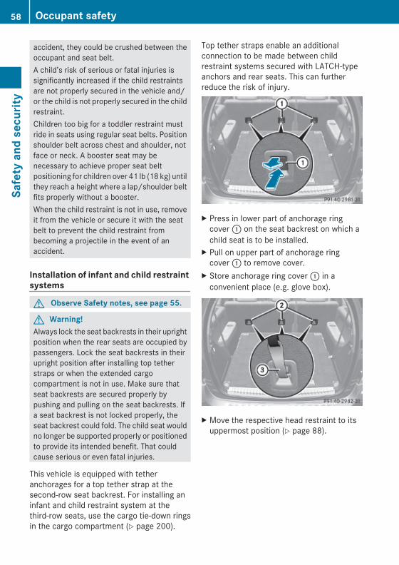
accident, they could be crushed between theoccupant and seat belt.A child’s risk of serious or fatal injuries issignificantly increased if the child restraintsare not properly secured in the vehicle and/or the child is not properly secured in the childrestraint.Children too big for a toddler restraint mustride in seats using regular seat belts. Positionshoulder belt across chest and shoulder, notface or neck. A booster seat may benecessary to achieve proper seat beltpositioning for children over 41 lb (18 kg) untilthey reach a height where a lap/shoulder beltfits properly without a booster.When the child restraint is not in use, removeit from the vehicle or secure it with the seatbelt to prevent the child restraint frombecoming a projectile in the event of anaccident.
Installation of infant and child restraint systems
G Observe Safety notes, see page 55.
G Warning!Always lock the seat backrests in their uprightposition when the rear seats are occupied bypassengers. Lock the seat backrests in theirupright position after installing top tetherstraps or when the extended cargocompartment is not in use. Make sure thatseat backrests are secured properly bypushing and pulling on the seat backrests. Ifa seat backrest is not locked properly, theseat backrest could fold. The child seat wouldno longer be supported properly or positionedto provide its intended benefit. That couldcause serious or even fatal injuries.
This vehicle is equipped with tetheranchorages for a top tether strap at thesecond-row seat backrest. For installing aninfant and child restraint system at thethird-row seats, use the cargo tie-down ringsin the cargo compartment (Y page 200).
Top tether straps enable an additionalconnection to be made between childrestraint systems secured with LATCH-typeanchors and rear seats. This can furtherreduce the risk of injury.
X Press in lower part of anchorage ringcover : on the seat backrest on which achild seat is to be installed.
X Pull on upper part of anchorage ringcover : to remove cover.
X Store anchorage ring cover : in aconvenient place (e.g. glove box).
X Move the respective head restraint to itsuppermost position (Y page 88).
58 Occupant safetySa
fety
and
sec
urity
X164_AKB; 5; 31, en-USd2ureepe, Version: 2.11.8.1
2009-09-11T12:30:16+02:00 - Seite 58

X Guide top tether strap ? between thehead restraint and top of the seat backrest.
X Securely fasten hook =, which is part oftop tether strap ?, to anchorage ring ;.
Make sureRhook = is attached to anchorage ring ;
beyond the safety catch, as illustratedRtop tether strap ? is not twistedRthe head restraint is installed and
positioned such that top tether strap ?can pass freely between the head restraintand top of the seat backrestRtop tether strap ? is positioned between
the seat backrest and the cargocompartment cover blind (if installed)Rtop tether strap ? is positioned between
the seat backrest and the cargo net (ifinstalled)
X Lower the head restraint if necessary(Y page 88).Make sure the top tether strap can passfreely between the head restraint and topof the seat backrest.
X Install the child restraint system andtighten the top tether strap according tothe child restraint manufacturer’sinstructions.
After removing the child restraint system andtop tether strap ?:X Reinstall anchorage ring cover :.
Child seat anchors – LATCH-type
G Observe Safety notes, see page 55.
G Warning!Children too big for a toddler restraint mustride in seats using regular seat belts. Positionshoulder belt across chest and shoulder, notface or neck.A booster seat may be necessary to achieveproper seat belt positioning for children over41 lb (18 kg) until they reach a height wherea lap/shoulder belt fits properly without abooster.Install child seat according to manufacturer’sinstructions.The child seat must be firmly attached to bothanchors.An incorrectly mounted child seat may comeloose during an accident which could result inserious injury or death to the child.Damaged or impact damaged child seats orchild seat mounting fittings must be replaced.
Each of the outboard second-row seats andthird-row seats has two LATCH-type anchorsfor the installation of a LATCH-type child seatwith matching mounting fittings.Non-LATCH-type child seats may also be usedand can be installed using the vehicle’s seatbelt system. Install child seat according to themanufacturer’s instructions.The LATCH-type anchors are blended withcovers.
Example, second-row seats
Occupant safety 59
Safe
ty a
nd s
ecur
ity
X164_AKB; 5; 31, en-USd2ureepe, Version: 2.11.8.1
2009-09-11T12:30:16+02:00 - Seite 59
Z

X Remove anchorage ring covers : fromanchors ; of the seat on which a child seatis to be installed.
Example, second-row seats
X Install a LATCH-type child seat accordingto the manufacturer’s instructions.A rigid connection between the child seatand the body of the vehicle is established.
X Make sure that the seat belt for the rearcenter seat can operate freely with a childseat installed.
Child safety
Child safety locksG Observe Safety notes, see page 55.
G Warning!Children could open a rear door from theinside. This may cause serious personal injuryor an accident. Therefore, secure the reardoors with the child safety locks wheneverchildren are riding in the back seats of thevehicle.
The child safety locks on the rear doorsenable you to secure each rear doorindividually. You cannot open a secured reardoor from the inside. You can open the reardoor from the outside when the vehicle isunlocked.
X Securing: Press the lever down in directionof arrow ;.
X Check to make sure the child safety locksare working properly.
X Releasing: Press the lever up in directionof arrow :.
Override switchG Observe Safety notes, see page 55.
With the override switch you can disable therear door window switches in the rear doorpanels. This can be useful, for instance, whenyou have children riding in the rear passengercompartment.
G Warning!Activate the override switch when childrenare riding in the back seats of the vehicle. Thechildren may otherwise injure themselves,e.g. by becoming trapped in the rear doorwindow opening.
X Activating: Press override switch :.The switch engages in recessed position.
60 Occupant safetySa
fety
and
sec
urity
X164_AKB; 5; 31, en-USd2ureepe, Version: 2.11.8.1
2009-09-11T12:30:16+02:00 - Seite 60

The rear door windows can no longer beoperated using the respective switchlocated in the rear doors.
You can still operate the rear door windowsusing the switches located on the doorcontrol panel of the driver’s door.X Deactivating: Press override switch :
again.The switch disengages from its recessedposition back to its original position.The rear door windows can be operatedagain using the respective switch locatedin the rear doors.
For more information on power windows, seethe “Controls in detail” section(Y page 105).
Panic alarm
Example illustration: SmartKey with KEYLESS-GO
X Activating: Press and hold !button : for at least 1 second.An audible alarm and flashing exteriorlamps will operate briefly.
X Deactivating: Press ! button : again.orX Insert the SmartKey into the starter switch.orX Press the KEYLESS-GO start/stop button.
The SmartKey with KEYLESS-GO must beinside the vehicle.
i USA only:This device complies with Part 15 of theFCC Rules. Operation is subject to thefollowing two conditions:1. This device may not cause harmful
interference, and2. this device must accept any
interference received, includinginterference that may cause undesiredoperation.
Any unauthorized modification to thisdevice could void the user’s authority tooperate the equipment.
i Canada only:This device complies with RSS-210 ofIndustry Canada. Operation is subject tothe following two conditions:1. This device may not cause interference,
and2. this device must accept any
interference received, includinginterference that may cause undesiredoperation of the device.
Any unauthorized modification to thisdevice could void the user’s authority tooperate the equipment.
Driving safety systems
IntroductionThis section contains information about thefollowing driving safety systems:RABS (Antilock Brake System)RBAS (Brake Assist System)REBP (Electronic Brake Proportioning)RESP® (Electronic Stability Program)
i In winter operation, the maximumeffectiveness of most of the drivingsystems described in this section is only
Driving safety systems 61
Safe
ty a
nd s
ecur
ity
X164_AKB; 5; 31, en-USd2ureepe, Version: 2.11.8.1
2009-09-11T12:30:16+02:00 - Seite 61
Z

achieved with winter tires, or snow chainsas required.
Safety notes
G Warning!The following factors increase the risk ofaccidents:RExcessive speed, especially in turnsRWet and slippery road surfacesRFollowing another vehicle too closely
The driving safety systems described in thissection cannot reduce these risks or preventthe natural laws of physics from acting on thevehicle. They cannot increase braking orsteering efficiency beyond that afforded bythe condition of the vehicle brakes and tiresor the traction afforded.Only a safe, attentive, and skillful driver canprevent accidents.The capabilities of a vehicle equipped with thedriving safety systems described in thissection must never be exploited in a recklessor dangerous manner which could jeopardizethe user’s safety or the safety of others.Always adjust your driving style to theprevailing road and weather conditions andkeep a safe distance to other road users andobjects on the street.If a driving system malfunctions, other drivingsafety systems may also switch off. Observeindicator and warning lamps that may comeon as well as messages in the multifunctiondisplay that may appear.
ABS
G Observe Safety notes, see page 62.
G Warning!Do not pump the brake pedal. Use firm, steadybrake pedal pressure instead. Pumping thebrake pedal defeats the purpose of the ABS
and significantly reduces brakingeffectiveness.
The Antilock Brake System (ABS) regulatesthe brake pressure so that the wheels do notlock during braking. This allows you tomaintain the ability to steer your vehicle.The ABS is functional above a speed ofapproximately 5 mph (8 km/h) independentof road surface conditions.On slippery road surfaces, the ABS willrespond even to light brake pressure.The ABS indicator lamp ! indicator lampin the instrument cluster comes on when youswitch on the ignition. It goes out when theengine is running.
BrakingAt the instant one of the wheels is about tolock up, a slight pulsation can be felt in thebrake pedal. The pulsation indicates that theABS is in the regulating mode.X Keep firm and steady pressure on the brake
pedal while you feel the pulsation.Continuous, steady brake pedal pressureyields the advantages provided by the ABS,namely braking power and the ability to steerthe vehicle.The pulsating brake pedal can be anindication of hazardous road conditions andfunctions as a reminder to take extra carewhile driving.
Emergency brake maneuverX Keep continuous full pressure on the brake
pedal.
G Warning!If the ABS malfunctions, other driving safetysystems such as the BAS or the ESP® are alsoswitched off. Observe indicator and warninglamps that may come on as well as messagesin the multifunction display that may appear.
62 Driving safety systemsSa
fety
and
sec
urity
X164_AKB; 5; 31, en-USd2ureepe, Version: 2.11.8.1
2009-09-11T12:30:16+02:00 - Seite 62

If the ABS malfunctions, the wheels may lockduring hard braking, reducing steeringcapability and extending the braking distance.
Off-road ABSWith the off-road driving program switchedon, or with the transmission in LOW RANGEmode, the ABS designed for off-road drivingis activated automatically.When applying the brakes at speeds below18 mph (30 km/h), the front wheels arelocked cyclically to shorten the brakingdistance (dig-in effect). This will restrictsteering the vehicle.
BAS
G Observe Safety notes, see page 62.The Brake Assist System (BAS) operates inemergency situations. If you apply the brakesvery quickly, the BAS provides full brakeboost automatically, thereby potentiallyreducing the braking distance.X Apply continuous full braking pressure until
the emergency braking situation is over.The ABS will prevent the wheels fromlocking.
When you release the brake pedal, the brakesfunction again as normal. The BAS is thendeactivated.
G Warning!If the BAS malfunctions, the brake system stillfunctions, but without the additional brakeboost available that the BAS would normallyprovide in an emergency braking maneuver.Therefore, the braking distance may increase.
EBP
G Observe Safety notes, see page 62.The Electronic Brake Proportioning (EBP)enhances braking effectiveness by allowingthe rear brakes to supply a greater proportion
of the braking effort in straight-line brakingwithout a loss of vehicle stability.
G Warning!If the EBP malfunctions, the brake system willstill function with full brake boost. However,the rear wheels could lock up duringemergency braking situations, for example.You could lose control of the vehicle andcause an accident.Adapt your driving style to the changeddriving characteristics.
ESP®
G Observe Safety notes, see page 62.The Electronic Stability Program (ESP®) isoperational as soon as the engine is running.It monitors the vehicle’s traction (force ofadhesive friction between the tires and theroad surface) and handling.The ESP® recognizes that the vehicle deviatesfrom the direction of travel as intended by thedriver. By applying brakes to individualwheels and by limiting the engine output, theESP® works to stabilize the vehicle. TheESP® is especially useful while driving off andon wet or slippery road surfaces. The ESP®
also stabilizes the vehicle during braking andsteering maneuvers.The ESP® warning lamp d in theinstrument cluster comes on when you switchon the ignition. It goes out when the engineis running.The ESP® warning lamp d in theinstrument cluster flashes when the ESP® isengaged.
Driving safety systems 63
Safe
ty a
nd s
ecur
ity
X164_AKB; 5; 31, en-USd2ureepe, Version: 2.11.8.1
2009-09-11T12:30:16+02:00 - Seite 63
Z
G Warning!Never switch off the ESP® when you see theESP® warning lamp d flashing in theinstrument cluster. In this case proceed asfollows:RWhen driving off, apply as little throttle as
possible.RWhile driving, ease up on the accelerator
pedal.RAdapt your speed and driving style to the
prevailing road conditions.
Failure to observe these guidelines couldcause the vehicle to skid. The ESP® cannotprevent accidents resulting from excessivespeed.
! Only conduct operational or performancetests on a two-axle dynamometer. If suchtests are necessary, contact an authorizedMercedes-Benz Center. You couldotherwise seriously damage the brakesystem or the transfer case which is notcovered by the Mercedes-Benz LimitedWarranty.
! Because the ESP® operatesautomatically, the engine and ignition mustbe shut off (SmartKey in starter switchposition 0 or 1 or KEYLESS-GO start/stopbutton in position 0 or 1) when the parkingbrake is being tested on a brake testdynamometer. Such testing should be nolonger than 10 seconds.Active braking action through the ESP®
may otherwise seriously damage the brakesystem which is not covered by theMercedes-Benz Limited Warranty.
! The ESP® will only function properly if youuse wheels of the recommended tire sizeas specified in the “Technical data” sectionof this Operator’s Manual.
i The Distronic system and cruise controlswitch off automatically when the ESP®
engages.
Electronic Traction System (4-ETS)
G Observe Safety notes, see page 62.The 4-ETS (four-wheel Electronic TractionSystem) is a component of the ESP®. The4-ETS improves the vehicle’s ability to utilizeavailable traction, especially under slipperyroad conditions by applying the brakes to aspinning wheel. In addition, more power istransferred to the wheel(s) with traction.When you switch off the ESP®, the 4-ETS isstill enabled.X If conditions require, switch on the off-road
driving program (Y page 158) or the LOWRANGE mode (Y page 119).
Off-road 4-ETSWith the off-road driving program switched on(Y page 158), or the transmission in LOWRANGE mode (Y page 120), the 4-ETSdesigned for off-road use is activatedautomatically.
Switching off the ESP®
G Warning!The ESP® should not be switched off duringnormal driving other than in thecircumstances described below. Disablingthe system will reduce vehicle stability indriving maneuvers.Do not switch off the ESP® when a sparewheel is mounted.
To improve the vehicle’s traction, switch offthe ESP®. This allows the drive wheels to spinand thus cut into surfaces for better grip, forexampleRwhen driving with snow chainsRin deep snowRin sand or gravel
64 Driving safety systemsSa
fety
and
sec
urity
X164_AKB; 5; 31, en-USd2ureepe, Version: 2.11.8.1
2009-09-11T12:30:16+02:00 - Seite 64

G Warning!Switch on the ESP® immediately if theaforementioned circumstances do not applyanymore. Otherwise the ESP® will notstabilize the vehicle when it is starting to skidor a wheel is spinning.
When you switch off the ESP®,Rthe ESP® does not stabilize the vehicleRthe engine output is not limited, which
allows the drive wheels to spin and thus cutinto surfaces for better gripRthe 4-ETS will still apply the brakes to a
spinning wheelRthe ESP® continues to operate when you
are brakingRthe cruise control or the Distronic system
cannot be activatedRthe cruise control or the Distronic system
switch off if activated
i When the ESP® is switched off and one ormore drive wheels are spinning, the ESP®
warning lamp d in the instrumentcluster flashes. However, the ESP® willthen not stabilize the vehicle.
X With the engine running, press ESP®
switch : until the ESP® warning lampd in the instrument cluster comes on.The ESP® is switched off.
G Warning!When the ESP® warning lamp d isilluminated continuously, the ESP® isswitched off or is not operational due to amalfunction. Vehicle stability in standarddriving maneuvers is reduced.Adapt your speed and driving to the prevailingroad conditions and to the non-operatingstatus of the ESP®.
! Avoid spinning of a drive wheel for anextended period with the ESP® switchedoff. This may cause serious damage to thedrivetrain which is not covered by theMercedes-Benz Limited Warranty.
Switching on the ESP®
X Press ESP® switch : until the ESP®
warning lamp d in the instrumentcluster goes out.You are now again in normal driving modewith the ESP® switched on.
Off-road ESP® With the off-road driving program switched on(Y page 158), or with the transmission inLOW RANGE mode (Y page 120), the ESP®
designed for off-road use is activatedautomatically. At speeds below 27 mph(45 km/h), the ESP® assists in over–understeering, thus improving vehicletraction.
ESP® trailer stabilization If the trailer you are towing should begin tosway, the rig can only be stabilized byimmediately applying the brakes hard.Steering during this maneuver will not help tostabilize the rig.The ESP® will assist you in such situations.The ESP® recognizes when the trailer startsswaying and will apply the brakes to reducethe vehicle speed to a non-critical speed that
Driving safety systems 65
Safe
ty a
nd s
ecur
ity
X164_AKB; 5; 31, en-USd2ureepe, Version: 2.11.8.1
2009-09-11T12:30:16+02:00 - Seite 65
Z

allows the vehicle-trailer combination tostabilize.The ESP® trailer stabilization is functional atvehicle speeds above approximately 40 mph(65 km/h) when the ESP® is switched on.
G Warning!The system will not be able to assist when thetrailer jackknifesRif the ESP® has switched off due to a
malfunctionRon wet or icy roadsRon roads with slippery surfaceRin sand or gravel
Trailers with a high center of gravity may tipover before the system recognizes swaying ofthe trailer.
Anti-theft systems
ImmobilizerThe immobilizer prevents unauthorizedpersons from starting your vehicle.When leaving the vehicle, always take theSmartKey with you and lock the vehicle. Theengine can be started by anyone with a validSmartKey that is left inside the vehicle.
ActivatingX With SmartKey: Remove the SmartKey
from the starter switch.X With KEYLESS-GO: Turn off the engine and
open the driver’s door.
DeactivatingX Switch on the ignition.
i Starting the engine will also deactivatethe immobilizer.In the event that the engine cannot bestarted (yet the vehicle’s battery ischarged), the system is not operational.Contact an authorized Mercedes-Benz
Center or call 1-800-FOR-MERCedes (in theUSA) or 1-800-387-0100 (in Canada).
Anti-theft alarm systemOnce the alarm system has been armed, avisual and audible alarm is triggered whensomeone opensRa doorRthe tailgateRthe hoodThe alarm will stay on even if the activatingelement, a door, for example, is closedimmediately.The alarm system will also be triggered whenRthe vehicle is opened with the mechanical
keyRa door is opened from the insideTo cancel the alarm after it has beentriggered, see “Canceling the alarm”(Y page 67).
i If the alarm stays on for more than30 seconds, the Tele Aid system initiates acall to the Response Center automatically.The Tele Aid system will initiate the callprovided thatRyou have subscribed to the Tele Aid
serviceRthe Tele Aid service has been activated
properlyRthe necessary mobile phone, power
supply and GPS coverage are available
66 Anti-theft systemsSa
fety
and
sec
urity
X164_AKB; 5; 31, en-USd2ureepe, Version: 2.11.8.1
2009-09-11T12:30:16+02:00 - Seite 66

X Arming: Lock the vehicle with theSmartKey or with KEYLESS-GO.The turn signal lamps flash three times toindicate that the vehicle is locked. Indicatorlamp : flashes to indicate that the alarmsystem is armed.
i If the turn signal lamps do not flash threetimes, a door or the tailgate may not beproperly closed.Close the respective element.
X Disarming: Unlock the vehicle with theSmartKey or with KEYLESS-GO.The turn signal lamps flash once to indicatethat the alarm system is disarmed.
i Unless you open a door or the tailgatewithin approximately 40 seconds afterunlocking the vehicle:RThe vehicle will be locked again.RThe anti-theft alarm system will be
rearmed.
Canceling the alarmTo cancel the alarm, do one of the following:X Insert the SmartKey into the starter switch.X Press button % or & on the
SmartKey.
In vehicles with KEYLESS-GO:X Grasp an outside door handle.
The SmartKey must be within 3 ft (1 m) ofthe vehicle.
X Press the KEYLESS-GO start/stop button.The SmartKey must be inside the vehicle.
Anti-theft systems 67
Safe
ty a
nd s
ecur
ity
X164_AKB; 5; 31, en-USd2ureepe, Version: 2.11.8.1
2009-09-11T12:30:16+02:00 - Seite 67
Z

68
X164_AKB; 5; 31, en-USd2ureepe, Version: 2.11.8.1
2009-09-11T12:30:16+02:00 - Seite 68

Vehicle equipment .............................. 70Locking and unlocking ....................... 70Starter switch positions ..................... 80Seats .................................................... 82Multifunction steering wheel ............. 91Mirrors ................................................. 93Memory function ................................. 96Lighting ................................................ 97Wipers ................................................ 103Power windows ................................. 105Driving and parking .......................... 108Automatic transmission ................... 114Transfer case .................................... 119Differential locks .............................. 121Instrument cluster ............................ 124Control system .................................. 125Driving systems ................................ 144Overview of climate control sys-tem functions and air vents ............. 172Climate control ................................. 1753-zone automatic climate control . . . 181Rear window defroster ..................... 191Power tilt/sliding sunroof ............... 192Loading and storing .......................... 194Useful features ................................. 209
69
Cont
rols
in d
etai
l
X164_AKB; 5; 31, en-USd2ureepe, Version: 2.11.8.1
2009-09-11T12:30:16+02:00 - Seite 69

Vehicle equipment
i This Operator’s Manual describes allfeatures, standard or optional, potentiallyavailable for your vehicle at the time ofpurchase. Please be aware that yourvehicle might not be equipped with allfeatures described in this manual.
Locking and unlocking
Notes
G Observe Safety notes, see page 55.When unlocking the vehicle, all turn signallamps flash once. The locking knobs in thedoors move up. The anti-theft alarm systemis disarmed.When locking the vehicle, all turn signal lampsflash three times. The locking knobs in thedoors move down. The anti-theft alarmsystem is armed.All doors and the tailgate must be closed.If you cannot lock or unlock the vehicle withthe SmartKey, the batteries in the SmartKeyare discharged, the SmartKey ismalfunctioning, or the vehicle battery isdrained.X Check the batteries in the SmartKey
(Y page 73) and replace them ifnecessary.
X Use the mechanical key to unlock thedriver’s door (Y page 323).
X Use the mechanical key to lock the vehicle(Y page 324).
X Have the vehicle battery and the vehiclebattery connections checked at anauthorized Mercedes-Benz Center.
If the SmartKey is malfunctioning, contactRoadside Assistance or an authorizedMercedes-Benz Center.
SmartKeyYour vehicle comes supplied with twoSmartKeys, each with remote control and aremovable mechanical key.The SmartKey centrally locks and unlocks:Rthe doorsRthe tailgateRthe fuel filler flap
Example illustration: SmartKey with KEYLESS-GO: & Lock button; F Unlock button for tailgate= % Unlock button
i USA only:This device complies with Part 15 of theFCC Rules. Operation is subject to thefollowing two conditions:1. This device may not cause harmful
interference, and2. this device must accept any
interference received, includinginterference that may cause undesiredoperation.
Any unauthorized modification to thisdevice could void the user’s authority tooperate the equipment.
70 Locking and unlockingCo
ntro
ls in
det
ail
X164_AKB; 5; 31, en-USd2ureepe, Version: 2.11.8.1
2009-09-11T12:30:16+02:00 - Seite 70

i Canada only:This device complies with RSS-210 ofIndustry Canada. Operation is subject tothe following two conditions:1. This device may not cause interference,
and2. this device must accept any
interference received, includinginterference that may cause undesiredoperation of the device.
Any unauthorized modification to thisdevice could void the user’s authority tooperate the equipment.
Factory setting X Global unlocking: Press button %.Unless you open a door or the tailgate withinapproximately 40 seconds after unlockingthe vehicle:RThe vehicle will be locked again.RThe antitheft alarm system will be rearmed.X Global locking: Press button &.
Selective setting If you frequently travel alone, you may wishto reprogramm the SmartKey. Pressingbutton % will then only unlock the driver’sdoor and the fuel filler flap.X Switching on/off: Press and hold buttons% and & simultaneously forapproximately 6 seconds until the batterycheck lamp (Y page 73) flashes twice.
The SmartKey will then function as follows:X Unlocking driver’s door and fuel filler
flap: Press button % once.X Global unlocking: Press button %
twice.X Global locking: Press button &.
KEYLESS-GOVehicles equipped with KEYLESS-GO comewith two SmartKeys with KEYLESS-GO, eachwith remote control and a removablemechanical key.The KEYLESS-GO function is integrated intothe SmartKey. The validity of the SmartKey ischecked every time you grasp an outside doorhandle.When the SmartKey is valid, your vehicleunlocksRthe doorsRthe fuel filler flapRthe tailgate
i USA only:This device complies with Part 15 of theFCC Rules. Operation is subject to thefollowing two conditions:1. This device may not cause harmful
interference, and2. this device must accept any
interference received, includinginterference that may cause undesiredoperation.
Any unauthorized modification to thisdevice could void the user’s authority tooperate the equipment.
i Canada only:This device complies with RSS-210 ofIndustry Canada. Operation is subject tothe following two conditions:1. This device may not cause interference,
and2. this device must accept any
interference received, includinginterference that may cause undesiredoperation of the device.
Any unauthorized modification to thisdevice could void the user’s authority tooperate the equipment.
Locking and unlocking 71
Cont
rols
in d
etai
l
X164_AKB; 5; 31, en-USd2ureepe, Version: 2.11.8.1
2009-09-11T12:30:16+02:00 - Seite 71
Z

Important notes on using KEYLESS-GO RYou can also use the SmartKey with
KEYLESS-GO like a normal SmartKey(Y page 70).RYou can combine KEYLESS-GO functions
with normal SmartKey functions (e.g.unlocking with KEYLESS-GO and lockingwith button &).RAlways carry the SmartKey with you.RNever store the SmartKey together with:
- Electronic items such as a mobile phoneor another SmartKey
- Metallic objects such as coins or metalfoil
Doing so could impair the function of theKEYLESS-GO system.RTo lock or unlock the vehicle, the SmartKey
must be located outside the vehicle withinapproximately 3 ft (1 m) of a door or thetailgate.RWhen the vehicle has been parked for more
than 72 hours, the KEYLESS-GO function isdeactivated. Pull an outside door handleand switch on the ignition once to activatethe KEYLESS-GO function.RIf the SmartKey is positioned farther away
from the vehicle, the system may no longerrecognize the SmartKey. The vehiclecannot be locked or the engine started viathe KEYLESS-GO system.RIf the SmartKey is removed from the vehicle
(e.g. if a passenger exits the vehicle withthe SmartKey)- when pressing the KEYLESS-GO start/
stop button or trying to lock the vehiclewith the lock button on an outside doorhandle the message Key Not Detected appears in the multifunctiondisplay
- with the engine running, the red messageKey Not Detected appears in themultifunction display while driving off
Find the SmartKey or change its presentlocation immediately (e.g. place it on thefront passenger seat or insert it in shirtpocket).RIf you have started the engine with the
KEYLESS-GO start/stop button, you canturn it off again by- pressing the KEYLESS-GO start/stop
button- inserting the SmartKey into the starter
switch when the vehicle is at a standstilland the automatic transmission is in parkposition P
RThe vehicle could be inadvertentlyunlocked if the SmartKey is within 3 ft (1 m)of the vehicle and- an outside door handle is splashed with
wateror
- you attempt to clean an outside doorhandle
RRemember that the engine can be startedby anyone with a SmartKey that is leftinside the vehicle.Possibility 1 (One SmartKey in the vehicle,one SmartKey outside the vehicle):If you leave the SmartKey behind whenexiting and locking the vehicle, no messageappears in the multifunction display.Possibility 2 (One SmartKey in the vehicle,no SmartKey outside the vehicle):When exiting and trying to lock the vehicle,the message Key Detected In Vehicleappears in the multifunction display. Thevehicle will not be locked.
Factory setting X Global unlocking: Grasp an outside door
handle.
72 Locking and unlockingCo
ntro
ls in
det
ail
X164_AKB; 5; 31, en-USd2ureepe, Version: 2.11.8.1
2009-09-11T12:30:16+02:00 - Seite 72

Unless you open a door or the tailgate withinapproximately 40 seconds after unlockingthe vehicle:RThe vehicle will be locked again.RThe antitheft alarm system will be rearmed.
X Global locking: Press lock button : on anoutside door handle.
Selective setting If you frequently travel alone, you may wishto reprogram the SmartKey. Grasping thedriver’s outside door handle will then onlyunlock the driver’s door and the fuel filler flap.X Switching on/off: Press and hold buttons% and & simultaneously forapproximately 6 seconds until the batterycheck lamp (Y page 73) flashes twice.
The SmartKey will then function as follows:X Unlocking driver’s door and fuel filler
flap: Grasp the driver’s outside doorhandle.
X Global unlocking: Grasp any outside doorhandle other than the driver’s outside doorhandle.
X Global locking: Press lock button : on anoutside door handle.
Checking SmartKey batteries
Example illustration: SmartKey with KEYLESS-GO
X Press button & or % on theSmartKey.Battery check lamp : comes on briefly toindicate that the SmartKey batteries are inorder.
If the battery check lamp does not come onbriefly during check, the SmartKey batteriesare discharged.X Replace the batteries (Y page 326).
i You can obtain the required batteries atany authorized Mercedes-Benz Center.
i If the batteries are checked within signalrange of the vehicle, pressing button& or % will lock or unlock the vehicleaccordingly.
Loss of the SmartKeyIf you lose your SmartKey or mechanical key,you should do the following:X Have the SmartKey deactivated by an
authorized Mercedes-Benz Center.X Report the loss of the SmartKey or the
mechanical key to your car insurancecompany immediately.
X Have the mechanical lock replaced ifnecessary.
Any authorized Mercedes-Benz Center will beglad to supply you with a replacement. For
Locking and unlocking 73
Cont
rols
in d
etai
l
X164_AKB; 5; 31, en-USd2ureepe, Version: 2.11.8.1
2009-09-11T12:30:16+02:00 - Seite 73
Z

information on replacing the SmartKey, see“Replacing the SmartKey” (Y page 74).
Replacing the SmartKeyOnly you, or someone authorized by you canorder a replacement key from any Mercedes-Benz Center. In order to do so, the Mercedes-Benz Center will require proof of identity andvehicle ownership with original documents,including the following:If you are the current owner of the vehicle:Rthe vehicle’s current state registrationRa current identity card, passport, or drivers
licenseIf you are an authorized person:Rthe vehicle’s current state registrationRa current identity card, passport, or drivers
license for the authorized individualRsigned and dated authorization from the
owner of the vehicle for which the key isbeing requested
i Duplicated or photocopieddocumentation will not be accepted.
Activating the keyOnce you, or an authorized person, hasprovided the appropriate documents, theMercedes-Benz Center will need tosynchronize the key to your vehicle before itcan be used. In order to do so, the Mercedes-Benz Center need access to your vehicle.
Opening the doors from the insideYou can open a door from the inside evenwhen it is locked unless it is secured with thechild safety lock (Y page 60).Open door only when conditions are safe todo so.
Example illustration driver’s door
If the vehicle has previously been locked withthe SmartKey or with KEYLESS-GO, openinga door from the inside will trigger the anti-theft alarm system.To cancel the alarm, see (Y page 67).X Front doors: Pull on inside door
handle ; on the respective front door.If the door was locked, locking knob : willmove up.
X Rear doors: Pull up locking knob on therespective rear door to unlock door.
X Pull on the inside door handle on therespective rear door.
Automatic central lockingThe doors and the tailgate lock automaticallywhen the vehicle is set into motion.You can open a locked front door from theinside. Open door only when conditions aresafe to do so.The doors are designed to unlockautomatically after an accident if the force ofthe impact exceeds a preset threshold.The vehicle locks automatically when theignition is switched on and the wheels areturning at vehicle speeds of above 9 mph(15 km/h). You could therefore lock yourselfout when the vehicle is pushed or towed or ison a test stand.
i You can also activate or deactivate theautomatic central locking using the controlsystem (Y page 138).
74 Locking and unlockingCo
ntro
ls in
det
ail
X164_AKB; 5; 31, en-USd2ureepe, Version: 2.11.8.1
2009-09-11T12:30:16+02:00 - Seite 74

Locking and unlocking from the inside
G Observe Safety notes, see page 55.You can lock or unlock the vehicle from theinside using the central locking switches. Thiscan be useful, for example, if you want to lockthe vehicle before starting to drive.The central locking switches do not lock orunlock the fuel filler flap.The switches are located in each front door.
X Locking: Press central locking switch ;.When all doors and the tailgate are closed,the vehicle locks.
X Unlocking: Press central unlockingswitch :.
You can open a locked front door from theinside at any time. Open door only whenconditions are safe to do so.If the vehicle was previously locked with thecentral locking switchRand the SmartKey is set to factory settings,
the complete vehicle is unlocked when afront door is opened from the insideRand the SmartKey is set to selective
settings, only the front door opened fromthe inside is unlocked
If the vehicle has been locked centrally withthe SmartKey or with KEYLESS-GO, it will notunlock using the central unlocking switch.
Tailgate
G Warning!Make sure the tailgate is closed when theengine is running and while driving. Amongother dangers, deadly carbon monoxide (CO)gases may enter vehicle interior resulting inunconsciousness and death.
A minimum height clearance of 7.40 ft(2.25 m) is required to open the tailgate.
Opening the tailgate from the outside
X Pull on handle :.In vehicles without KEYLESS-GO: Thevehicle must be unlocked.
X Pull tailgate upwards to open.
Closing the tailgate from the outside
G Observe Safety notes, see page 55.
G Warning!To prevent possible personal injury, alwayskeep hands and fingers away from the cargocompartment opening when closing thetailgate. Be especially careful when smallchildren are around.
Locking and unlocking 75
Cont
rols
in d
etai
l
X164_AKB; 5; 31, en-USd2ureepe, Version: 2.11.8.1
2009-09-11T12:30:16+02:00 - Seite 75
Z

X Lower tailgate by pulling firmly onhandles :.
X Close tailgate with hands placed flat on it.Once the tailgate touches the latch, thetailgate will pull itself shut automatically.
Opening the tailgate from the inside
G Warning!Do not leave children unattended in thevehicle. Children could open the tailgate fromthe inside, which could result in an accidentand/or serious personal injury.
! Always make sure there is sufficientoverhead clearance.
You can unlock the tailgate from the third-rowseats and then open it manually.
X Push handle : in direction of arrow ; andhold it there.
X From this position, lift handle : indirection of arrow = and hold it there.The tailgate is released and can be openedmanually.
i If you do not open the tailgate within a fewseconds, the tailgate lock will engage againautomatically. Additionally, the tailgate willrelock automatically if the vehicle waslocked when the tailgate was released fromthe inside.If the tailgate lock does not engageautomatically and, if applicable, the tailgatedoes not relock after a few seconds, youhave to close the tailgate manually(Y page 75).
Power tailgate
G Warning!Make sure the tailgate is closed when theengine is running and while driving. Amongother dangers, deadly carbon monoxide (CO)gases may enter vehicle interior resulting inunconsciousness and death.
! The tailgate swings open upwardsautomatically. Always make sure there issufficient overhead clearance.
A minimum height clearance of 7.40 ft(2.25 m) is required to open the tailgate.In vehicles with power tailgate, you canRopen and close the tailgate from the inside
and the outside electricallyRlimit the opening height of the tailgateRinterrupt the opening/closing procedure at
any time by- pressing or pulling the door-mounted
remote tailgate opening/closing switch- pulling the outside handle on the tailgate
76 Locking and unlockingCo
ntro
ls in
det
ail
X164_AKB; 5; 31, en-USd2ureepe, Version: 2.11.8.1
2009-09-11T12:30:16+02:00 - Seite 76

- pressing the tailgate closing switch- pressing the KEYLESS-GO locking/
closing switch
Notes for operating the tailgate with theSmartKey:You can also open, close, and stop thetailgate by pressing button F on theSmartKey.The prerequisites for this are:RNo SmartKey is inserted in the starter
switch.RKEYLESS-GO: The vehicle’s on-board
electronics must have status 0(Y page 80).
Opening the tailgate from the outsideYou can unlock and open the tailgatesimultaneously from the outside when thevehicle is stationary.X Press and hold button F on the
SmartKey until the tailgate unlocks andbegins to open.While the tailgate is opening, an acousticwarning sounds.
orX Vehicles with KEYLESS-GO: Pull on the
handle (Y page 75).
Closing the tailgate from the outside
G Observe Safety notes, see page 55.
G Warning!Monitor the closing procedure carefully tomake sure no one is in danger of beinginjured. To prevent possible personal injury,always keep hands and fingers away from thecargo compartment opening when closing thetailgate. Be especially careful when smallchildren are around. To stop the closingprocedure, do one of the following:
RPress or pull the remote tailgate opening/closing switch on the driver’s door.RPress the tailgate closing switch.RPress the KEYLESS-GO locking/closing
switch.RPull outside handle on the tailgate.RWhen no SmartKey is inserted in the starter
switch (vehicles with KEYLESS-GO: Makesure the vehicle’s on-board electronicshave status 0): Press button F on theSmartKey.
Do not leave the SmartKey in the vehicle. Youmay lock yourself out.If the vehicle was previously centrally lockedwith the SmartKey or KEYLESS-GO, thetailgate will lock automatically when it isclosed. The turn signal lamps flash threetimes to confirm locking.
Vehicles without KEYLESS-GO
Vehicles with KEYLESS-GO
Locking and unlocking 77
Cont
rols
in d
etai
l
X164_AKB; 5; 31, en-USd2ureepe, Version: 2.11.8.1
2009-09-11T12:30:16+02:00 - Seite 77
Z

X Press tailgate closing switch : or pressand hold button F on the SmartKey untilthe tailgate begins to close.
If the tailgate comes into contact with anobject while closing, the closing procedure isstopped and the tailgate reopens. This mayhappen if luggage has been piled too high, forexample.
Closing the tailgate and locking the vehicle from the outside (vehicles with KEYLESS-GO)
G Observe Safety notes, see page 55.
G Warning!Monitor the closing procedure carefully tomake sure no one is in danger of beinginjured. To prevent possible personal injury,always keep hands and fingers away from thecargo compartment opening when closing thetailgate. Be especially careful when smallchildren are around. To stop the closingprocedure, do one of the following:RPress or pull the remote tailgate opening/
closing switch on the driver’s door.RPress the tailgate closing switch.RPress the KEYLESS-GO locking/closing
switch.RPull outside handle on the tailgate.RWhen no SmartKey is inserted in the starter
switch (vehicles with KEYLESS-GO: Makesure the vehicle’s on-board electronicshave status 0): Press button F on theSmartKey.
You can close the tailgate and lock the vehiclesimultaneously from the outside using theKEYLESS-GO locking/closing switch.
X Make sure you have the SmartKey with you.X Press KEYLESS-GO locking/closing
switch : briefly.The tailgate closes.Once the tailgate and all doors are closed:RThe vehicle locks.RThe turn signals flash three times to
confirm locking.RThe locking knobs in the doors move
down.RThe anti-theft alarm system is armed.
If the tailgate comes into contact with anobject while closing, the closing procedure isstopped and the tailgate reopens. This mayhappen if luggage has been piled too high, forexample.The closing process is stopped if the systemcannot recognize a SmartKey with KEYLESS-GO anymore. Make sure the SmartKey withKEYLESS-GO is within approximately 3 ft(1 m) of the tailgate. Repeat the closingprocedure if necessary.The tailgate remains unlocked when aSmartKey with KEYLESS-GO is recognizedinside the vehicle to prevent a possibleinadvertent lockout. In this case, the turnsignals will not flash and the anti-theft alarmwill be triggered when the tailgate is opened.
78 Locking and unlockingCo
ntro
ls in
det
ail
X164_AKB; 5; 31, en-USd2ureepe, Version: 2.11.8.1
2009-09-11T12:30:16+02:00 - Seite 78

Opening/closing the tailgate from the inside
OpeningG Observe Safety notes, see page 76.
G Warning!Maintain sight of the area around the rear ofthe vehicle while operating the tailgate withthe door-mounted remote tailgate switch.Monitor the opening procedure carefully tomake sure no one is in danger of beinginjured.To interrupt the opening procedure, press orpull the door-mounted remote tailgate switch.When the SmartKey is not inserted in thestarter switch (vehicles with KEYLESS-GO:Make sure the vehicle’s on-board electronicshave status 0): Press button F on theSmartKey.
You can unlock and open the tailgatesimultaneously from the driver’s seat whenthe vehicle is stationary.
X Pull remote tailgate opening/closingswitch : until the tailgate begins to open.While the tailgate is opening, an acousticwarning sounds.
ClosingG Observe Safety notes, see page 55.
G Warning!Maintain sight of the area around the rear ofthe vehicle while operating the tailgate with
the door-mounted remote tailgate switch.Monitor the closing procedure carefully tomake sure no one is in danger of beinginjured.To interrupt the closing procedure, press orpull the door-mounted remote tailgate switch.
If the tailgate comes into contact with anobject while closing, the closing procedure isstopped and the tailgate reopens. This mayhappen if luggage has been piled too high, forexample.X Turn the SmartKey in the starter switch to
position 1 or 2.X Press remote tailgate opening/closing
switch : until the tailgate begins to close.While the tailgate is closing an acousticwarning sounds.
X Interrupting the closing procedure:Press or pull remote tailgate opening/closing switch :.
Limiting opening height of tailgateYou can limit the opening height of thetailgate in the upper opening range. This canbe useful, for example, when the space abovethe tailgate is not sufficient.
ActivatingX Open the tailgate: Pull on handle
(Y page 75) or press and hold buttonF on the SmartKey until the tailgateopens.
X Stop opening procedure: When thetailgate is in the desired position, presstailgate closing switch (Y page 78) or pullon handle once more.
X You can also press or pull the remotetailgate opening/closing switch(Y page 79) to stop the opening procedure.
Locking and unlocking 79
Cont
rols
in d
etai
l
X164_AKB; 5; 31, en-USd2ureepe, Version: 2.11.8.1
2009-09-11T12:30:16+02:00 - Seite 79
Z

X Press and hold the tailgate closing switchin the tailgate (Y page 78) until you hear ashort acoustic signal.The opening height of the tailgate is limited.The tailgate will now stop at the storedposition when opened.
DeactivatingX Press and hold the tailgate closing switch
in the tailgate (Y page 78) until you heartwo short, consecutive acoustic signals.
Starter switch positions
SmartKey
G Observe Safety notes, see page 55.
Starter switchg For removing SmartKey1 Power supply for some electrical
consumers, e.g. radio2 Ignition (power supply for all electrical
consumers) and driving position 3 Starting position
When you switch on the ignition, all lamps(except low-beam headlamp indicator lamp,high-beam headlamp indicator lamp, and turnsignal indicator lamps unless activated) in theinstrument cluster come on. If a lamp in theinstrument cluster fails to come on when theignition is switched on, have it checked andreplaced if necessary. If a lamp in theinstrument cluster remains on after startingthe engine or comes on while driving, refer to“Lamps in instrument cluster” (Y page 314).
X Always remove the SmartKey from thestarter switch when the engine is not inoperation.This will help to prevent accelerated vehiclebattery discharge or a completelydischarged vehicle battery.
If the SmartKey cannot be turned in thestarter switch, the vehicle battery may not besufficiently charged.X Check the vehicle battery and charge it if
necessary.orX Get a jump start.
i If the SmartKey does not belong to thevehicle, the SmartKey can be turned in thestarter switch. However, the ignition doesnot switch on and the engine does not start.
KEYLESS-GO
G Observe Safety notes, see page 55.Vehicles equipped with the KEYLESS-GOfeature are supplied with a SmartKey withintegrated KEYLESS-GO function and aremovable KEYLESS-GO start/stop button.The KEYLESS-GO start/stop button must beinserted in the starter switch and theSmartKey present in the vehicle.Pressing the KEYLESS-GO start/stop buttonwithout depressing the brake pedalcorresponds to the various starter switchpositions (Y page 80).Pressing the KEYLESS-GO start/stop buttonwith the brake pedal firmly depressed willstart the engine (Y page 108).The KEYLESS-GO start/stop button can bepulled out of the starter switch easily. You canthen insert the SmartKey into the starterswitch.
i The KEYLESS-GO start/stop button doesnot need to be removed from the starterswitch when you leave the vehicle.However, always take the SmartKey withyou when you leave the vehicle. As long as
80 Starter switch positionsCo
ntro
ls in
det
ail
X164_AKB; 5; 31, en-USd2ureepe, Version: 2.11.8.1
2009-09-11T12:30:16+02:00 - Seite 80
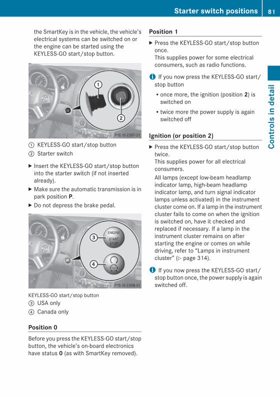
the SmartKey is in the vehicle, the vehicle’selectrical systems can be switched on orthe engine can be started using theKEYLESS-GO start/stop button.
: KEYLESS-GO start/stop button; Starter switch
X Insert the KEYLESS-GO start/stop buttoninto the starter switch (if not insertedalready).
X Make sure the automatic transmission is inpark position P.
X Do not depress the brake pedal.
KEYLESS-GO start/stop button= USA only? Canada only
Position 0Before you press the KEYLESS-GO start/stopbutton, the vehicle’s on-board electronicshave status 0 (as with SmartKey removed).
Position 1X Press the KEYLESS-GO start/stop button
once.This supplies power for some electricalconsumers, such as radio functions.
i If you now press the KEYLESS-GO start/stop buttonRonce more, the ignition (position 2) is
switched onRtwice more the power supply is again
switched off
Ignition (or position 2) X Press the KEYLESS-GO start/stop button
twice.This supplies power for all electricalconsumers.All lamps (except low-beam headlampindicator lamp, high-beam headlampindicator lamp, and turn signal indicatorlamps unless activated) in the instrumentcluster come on. If a lamp in the instrumentcluster fails to come on when the ignitionis switched on, have it checked andreplaced if necessary. If a lamp in theinstrument cluster remains on afterstarting the engine or comes on whiledriving, refer to “Lamps in instrumentcluster” (Y page 314).
i If you now press the KEYLESS-GO start/stop button once, the power supply is againswitched off.
Starter switch positions 81
Cont
rols
in d
etai
l
X164_AKB; 5; 31, en-USd2ureepe, Version: 2.11.8.1
2009-09-11T12:30:16+02:00 - Seite 81
Z

Seats
Safety notes
G Warning!In order to avoid possible loss of vehiclecontrol the following must be done before thevehicle is put into motion:Rseat adjustmentRhead restraint adjustmentRsteering wheel adjustmentRrear view mirror adjustmentRfastening of seat belts
G Warning!Do not adjust the driver’s seat while driving.Adjusting the seat while driving could causethe driver to lose control of the vehicle.Never ride in a moving vehicle with the seatbackrest in an excessively reclined position asthis can be dangerous. You could slide underthe seat belt in a collision. If you slide underit, the seat belt would apply force at theabdomen or neck. That could cause seriousor fatal injuries. The seat backrest and seatbelts provide the best restraint when thewearer is in a position that is as upright aspossible and seat belts are properlypositioned on the body.
G Warning!Your seat must be adjusted so that you cancorrectly fasten your seat belt.Observe the following points:RAdjust the seat backrest until your arms are
slightly angled when holding the steeringwheel.RAdjust the seat to a comfortable seating
position that still allows you to reach theaccelerator/brake pedal safely. Theposition should be as far back as possiblewith the driver still able to operate thecontrols properly.
RAdjust the head restraint so that it is asclose to the head as possible. The center ofthe head restraint must support the back ofthe head at eye level.RNever place hands under the seat or near
any moving parts while a seat is beingadjusted.
Failure to do so could result in an accidentand/or serious personal injury.
G Warning!The power seats can be operated at any time.Therefore, do not leave children unattendedin the vehicle, or with access to an unlockedvehicle. A child’s unsupervised access to avehicle could result in an accident and/orserious personal injury.
G Warning!According to accident statistics, children aresafer when properly restrained in the rearseating positions than in the front seatingposition. Thus, we strongly recommend thatchildren be placed in the rear seats wheneverpossible. Regardless of seating position,children 12 years old and under must beseated and properly secured in anappropriately sized infant restraint, toddlerrestraint, or booster seat recommended forthe size and weight of the child. For additionalinformation, see “Children in the vehicle”.A child’s risk of serious or fatal injuries issignificantly increased if the child restraintsare not properly secured in the vehicle and/or the child is not properly secured in the childrestraint.
G Warning!For your protection, drive only with properlypositioned head restraints.Adjust the head restraint so that it is as closeto the head as possible and the center of thehead restraint supports the back of the headat eye level. This will reduce the potential forinjury to the head and neck in the event of anaccident or similar situation.
82 SeatsCo
ntro
ls in
det
ail
X164_AKB; 5; 31, en-USd2ureepe, Version: 2.11.8.1
2009-09-11T12:30:16+02:00 - Seite 82

Do not drive the vehicle without the seat headrestraints. Head restraints are intended tohelp reduce injuries during an accident.
Seat adjustment! When moving the seats, make sure there
are no items in the footwell or behind theseats. Otherwise, you could damage theseats and/or the items.
Power seats ! When the second-row seats are folded
forward, e.g. for cargo volume expansion,the front seats may not be moved to therearmost position. Otherwise you coulddamage the front and second-row seats.
! When adjusting the seat backrest tilt andhead restraint height, make sure the sunvisor is folded up. If the head restraint is inthe uppermost position, it could hit anddamage the sun visor.
i Vehicles without memory function:The seats can be adjusted within 5 minutesafter either front door has been opened.The counter resets each timeRyou open or close a front doorRyou insert the SmartKey into the starter
switchRyou remove the SmartKey from the
starter switchRyou switch the ignition on or offJust like in vehicles with memory function,the power seats can be operated at anytime when the ignition is switched on.
i The memory function (Y page 96) letsyou store the settings for the seat positiontogether with the settings for the steeringwheel (electrical) and exterior rear viewmirrors.
X Seat fore and aft adjustment: Press theswitch forward or backward in direction ofarrow A.
X Seat backrest tilt: Press the switchforward or backward in direction ofarrow ?.
X Seat height: Press the switch up or downin direction of arrow =.
X Seat cushion tilt: Press the switch up ordown in direction of arrow ; until yourupper legs are lightly supported.
X Head restraint height (vehicles with memory function): Press the switch up ordown in direction of arrow :.
Head restraint height adjustment, manual This feature is only available in vehicleswithout memory function.
G Warning!For your protection, drive only with properlypositioned head restraints.Adjust the head restraint so that it is as closeto the head as possible and the center of thehead restraint supports the back of the headat eye level. This will reduce the potential forinjury to the head and neck in the event of anaccident or similar situation.Do not drive the vehicle without the seat headrestraints. Head restraints are intended tohelp reduce injuries during an accident.With a rear seat occupied, make sure to movethe respective head restraint up from the
Seats 83
Cont
rols
in d
etai
l
X164_AKB; 5; 31, en-USd2ureepe, Version: 2.11.8.1
2009-09-11T12:30:16+02:00 - Seite 83
Z

lowest non-use position and have theoccupant adjust the head restraint properly.
! Do not attempt to remove front seat headrestraints. They can only be removed byqualified technicians. We recommend thatyou have this work carried out by anauthorized Mercedes-Benz Center.
X Raising: Adjust the height of headrestraint : by pulling it upward.If head restraint : is fully retracted, pressrelease button ; in direction of arrow andpull head restraint : upward.
X Lowering: Press release button ; indirection of arrow and press down on headrestraint :.
Head restraint fore and aft adjustment G Warning!Vehicles with Rear Seat EntertainmentSystem: When adjusting the head restraint,make sure your fingers do not become caughtbetween the head restraint cushion and themonitor. Failing to do so may lead to injury.
X While seated, reach behind you with bothhands and find lower edge of the headrestraint.
X Push or pull on the lower edge of the headrestraint cushion to the desired position.
Comfort head restraint G Warning!When folding back the side cushions, neverreach between the side cushion and themounting post. You could otherwise betrapped.
You can adjust the side cushions of the headrestraints individually.X Adjusting side cushions: Pull or push side
cushions : into desired position.X Adjusting forward or backward: Pull or
push head restraint in direction ofarrow ;.
84 SeatsCo
ntro
ls in
det
ail
X164_AKB; 5; 31, en-USd2ureepe, Version: 2.11.8.1
2009-09-11T12:30:16+02:00 - Seite 84

Easy-entry/exit feature for third-row seats
This feature allows for easier access to andexit from the vehicle’s third-row seats.
G Warning!To help avoid personal injury, the second-rowseat backrests must be properly locked eitherin the upright position or, when using theexpanded cargo volume, in the fully foldedposition while the vehicle is in motion.
Easy-entry feature for third-row seatsThe lever for the easy-entry feature is locatedon the rear of the seat base of the passengerside second-row seat.
! Make sure the head restraint is pushed allthe way down.
X Pull and hold easy-entry lever : indirection of arrow at resistance point.The seat backrest folds forward.
X Pull and hold easy-entry lever : onceagain in direction of arrow at resistancepoint.
X Lift up the right second-row seat until itfolds forward.You should now have sufficient space toaccess the vehicle’s third-row seat.
i Vehicles with memory function:The front passenger seat moves slightlyforward.
Easy-entry/exit position
While the easy-entry feature is activated, youwill see, for example, the following messagein the multifunction display:2nd Row Of Seats - Right Not LockedX Return seat into its original position.
The message in the multifunction displaydisappears.
For setting the front passenger seat back intothe stored position, see “Recalling positionsfrom memory” (Y page 97).X Enter the vehicle.For information on how to fold down thesecond-row seats completely, see“Expanding cargo volume” (Y page 201).For setting the front passenger seat back intothe stored position, see “Recalling positionsfrom memory” (Y page 97).
Seats 85
Cont
rols
in d
etai
l
X164_AKB; 5; 31, en-USd2ureepe, Version: 2.11.8.1
2009-09-11T12:30:16+02:00 - Seite 85
Z

Easy-exit feature for third-row seatsThe easy-exit strap is located on the right rearof the second-row seat base.
Easy-exit strap
X To exit the vehicle when seated on a third-row seat, pull up and hold easy-exitstrap :.The right second-row seat backrest foldsforward.
X Pull and hold once easy-entry strap :.X Lift up the right second-row seat until it
folds forward.You should now have sufficient space toexit the vehicle’s third-row seat.
i Vehicles with memory function:The front passenger seat moves slightlyforward.
While the easy-entry feature is activated, youwill see, for example, the following messagein the multifunction display:2nd Row Of Seats - Right Not LockedX Return seat into its original position
(Y page 86).The message in the multifunction displaydisappears.
For setting the front passenger seat back intothe stored position, see “Recalling positionsfrom memory” (Y page 97).For information on how to fold down thesecond-row seats completely, see“Expanding cargo volume” (Y page 201).
Returning second-row seats to their original position
G Warning!When occupants have entered or exited thevehicle using the easy-entry/exit feature,before driving off make sureRthe seats are properly lockedRthe seat backrests are in an upright position
and are properly locked
If a seat and seat backrest are not properlylocked, the seat could move forward and theseat backrest could fold. You could slideunder the seat belt during braking, vehiclemaneuvers, or in an accident. If you slideunder it, the seat belt would apply force at theabdomen or neck. That could cause seriousor even fatal injuries.
X Fold seat back until it audibly engages.X Fold seat backrest back into original
position until it engages.To make sure the seat backrest hasengaged, lean firmly against the seatbackrest.
Emergency exit for third-row seatsi If, due to an accident or other situation, it
is not possible for you to exit the vehicle onthe side of the easy-entry seat(Y page 85), you can fold the left side of theseat backrest in the second row of seatsdown in order to open the left rear door.
86 SeatsCo
ntro
ls in
det
ail
X164_AKB; 5; 31, en-USd2ureepe, Version: 2.11.8.1
2009-09-11T12:30:16+02:00 - Seite 86

! Make sure the head restraint is pushed allthe way down.
X Pull emergency release : in the directionof arrow.
X Push seat backrest ; forwards.
G Warning!To help avoid personal injury when folding theseat backrest forward, make sure you moveboth feet and legs all the way back and out ofthe way to avoid them contacting the seat asit pivots forward.In order to prevent an accident or any otherpotentially dangerous situations whenopening the rear door and exiting the vehicle,make sure you are aware of the trafficsituation at all times.
X Open the left door.X Exit the vehicle.
Lumbar supportYou can adjust the contour of the driver’s seatlumbar support to help enhance support toyour spine.
X Curvature position: Use button : tomove the curvature up and button = tomove it down.
X Degree of curvature: Use button ; tolessen the curvature and button ? toincrease it.
Rear seats
G Warning!According to accident statistics, children aresafer when properly restrained in the rearseating positions than in the front seatingposition. Thus, we strongly recommend thatchildren be placed in the rear seats wheneverpossible. Regardless of seating position,children 12 years old and under must beseated and properly secured in anappropriately sized infant restraint, toddlerrestraint, or booster seat recommended forthe size and weight of the child. For additionalinformation, see “Children in the vehicle”.A child’s risk of serious or fatal injuries issignificantly increased if the child restraintsare not properly secured in the vehicle and/or the child is not properly secured in the childrestraint.
Rear seat adjustment
G Warning!Never ride in a moving vehicle with the seatbackrest in an excessively reclined position asthis can be dangerous. You could slide underthe seat belt in a collision. If you slide underit, the belt would apply force at the abdomenor neck. That could cause serious or fatalinjuries. The seat backrest and seat beltsprovide the best restraint when the wearer isin a nearly upright position and seat belts areproperly positioned on the body.Your seat must be adjusted so that you cancorrectly fasten your seat belt.Never place hands under the seat or near anymoving parts while a seat is being adjusted.After adjusting rear seats, make sureRthe seats are properly lockedRthe seat backrests are in an upright position
and are properly locked
Check for secure locking by pushing andpulling on the seat backrests. If a seat andseat backrest are not properly locked, theseat could move forward and the seat
Seats 87
Cont
rols
in d
etai
l
X164_AKB; 5; 31, en-USd2ureepe, Version: 2.11.8.1
2009-09-11T12:30:16+02:00 - Seite 87
Z

backrest could fold. The child seat would nolonger be properly supported or positioned toprovide its intended benefit.
Seat backrest tilt (second-row seats)
G Warning!The seat belt only offers its intendedprotection when the seat backrest is in anearly vertical position and the occupant issitting upright. Avoid sitting in positions thatprevent the seat belt from being properlypositioned against the body. You shouldtherefore adjust the seat backrest to aposition as upright as possible.
The seat backrest tilt can be set to fivedifferent positions.
X While seated, pull adjustment handle : indirection of arrow to resistance point andhold it there.
X To move seat backrest back, lean lightlyagainst the seat backrest.
X To move seat backrest forward, leanforward with adjustment handle : pulledand held at resistance point.The seat backrest will move forwardagainst your back.
X Release adjustment handle : when theseat backrest has reached the desiredposition.To make sure the seat backrest hasengaged, lean firmly against the seatbackrest.
Head restraint height
G Warning!With a rear seat occupied, make sure to movethe respective head restraint up from thelowest non-use position and have theoccupant adjust the head restraint properly.For your protection, drive only with properlypositioned head restraints.Adjust the head restraint so that it is as closeto the head as possible and the center of thehead restraint supports the back of the headat eye level. This will reduce the potential forinjury to the head and neck in the event of anaccident or similar situation.
Second-row seat head restraint
X Raising: Manually adjust the height of headrestraint : by pulling it upward to thedesired position.
X Lowering: Push release button ; andpress down on head restraint :.
i The third-row seat head restraints areadjusted in the same manner.
88 SeatsCo
ntro
ls in
det
ail
X164_AKB; 5; 31, en-USd2ureepe, Version: 2.11.8.1
2009-09-11T12:30:16+02:00 - Seite 88

Head restraint fore and aft adjustment
The angle of the head restraint for the outersecond-row seats or the third-row seats canbe adjusted manually.X While seated, reach behind you with both
hands and find lower edge of the headrestraint.
X Adjust the head restraint to the desiredposition by pushing or pulling on the loweredge of the head restraint cushion.
Head restraints, removing and installing
G Warning!Do not drive the vehicle without the seat headrestraints installed when the rear seats areoccupied. Head restraints are intended tohelp reduce injuries during an accident.With a rear seat occupied, make sure to movethe respective head restraint up from thelowest non-use position and have theoccupant adjust the head restraint properly.For your protection, drive only with properlypositioned head restraints.Adjust the head restraint in such a way that itis as close to the head as possible and thecenter of the head restraint supports the backof the head at eye level. This will reduce thepotential for injury to the head and neck in theevent of an accident or similar situation.
Second-row seat head restraint
RemovingX Second-row seat: Fold the seat backrest
forward (Y page 88).X Third-row seat: Fold the seat backrest
forward (Y page 201).X Pull head restraint : to its uppermost
position.X Press release button ; and pull out head
restraint :.X Second-row seat: Fold the seat backrest
rearward until it engages.X Third-row seat: Fold the seat backrest
rearward (Y page 201).
InstallingX Second-row seat: Fold the seat backrest
forward (Y page 88).X Third-row seat: Fold the seat backrest
forward (Y page 201).X Insert head restraint : into openings on
the seat backrest.X Push head restraint : down until it audibly
engages.X Push release button ; and adjust head
restraint : to the desired position(Y page 88).
X Second-row seat: Fold the seat backrestrearward until it engages.
X Third-row seat: Fold the seat backrestrearward (Y page 201).
Seats 89
Cont
rols
in d
etai
l
X164_AKB; 5; 31, en-USd2ureepe, Version: 2.11.8.1
2009-09-11T12:30:16+02:00 - Seite 89
Z

Multicontour seatsThe multicontour seat has a movable seatcushion and inflatable air cushions built intothe seat backrest to provide additionallumbar and side support.
X Switch on the ignition.X Seat cushion depth: Adjust the seat
cushion depth to the length of your upperleg using switch :.
X Seat backrest contour: Adjust thecontour of the seat backrest to the desiredposition using W or X.
X Move the seat backrest support cushion tothe bottom with button ? or to the centerwith button =.
X Seat backrest side bolsters: Adjust theside bolsters so that they provide goodlateral support using switch ;.
Seat ventilation
The blue indicator lamps ; in seat ventilationswitch : come on to show which ventilationlevel you have selected.
i The seat ventilation for the driver’s seatcan be activated using the summer openingfeature (Y page 107).
X Switch on the ignition.X Switching on: Press respective seat
ventilation switch :.Three blue indicator lamps ; in seatventilation switch : come on.
X Press seat ventilation switch : repeatedlyuntil the desired ventilation level is set.
X Switching off: Press seat ventilationswitch : repeatedly until all indicatorlamps ; go out.
If there is insufficient voltage the seatventilating switches off automatically.
Seat heating
Front seat heating switches
The switches for the outboard second-rowseat heating are located in the rear centerconsole.
90 SeatsCo
ntro
ls in
det
ail
X164_AKB; 5; 31, en-USd2ureepe, Version: 2.11.8.1
2009-09-11T12:30:16+02:00 - Seite 90

Rear seat heating switches
The red indicator lamps ; in front or rearseat heating switch : come on to showwhich heating level you have selected.The seat heating switches from level 3 (high)to level 2 after approximately 5 minutes.The seat heating switches from level 2 to level1 (low) after approximately 10 minutes.After approximately 20 minutes in level 1, theseat heating switches off automatically.X Switch on the ignition.X Switching on: Press respective seat
heating switch :.Three red indicator lamps ; in therespective seat heating switch : come on.
X Continue pressing respective seat heatingswitch : until desired seat heating level isreached.
X Switching off: Press respective seatheating switch : repeatedly until allindicator lamps ; go out.
If one or more of indicator lamps ; inrespective seat heating switch : areflashing, there is insufficient voltage availablesince too many electrical consumers areturned on. The seat heating switches offautomatically.The seat heating will switch back on againautomatically as soon as sufficient voltage isavailable.
Multifunction steering wheel
Safety notes
G Warning!Do not adjust the steering wheel while driving.Adjusting the steering wheel while driving, ordriving without the steering wheel adjustmentfeature locked could cause the driver to losecontrol of the vehicle.The electrical steering wheel adjustmentfeature can be operated at any time.Therefore, do not leave children unattendedin the vehicle, or with access to an unlockedvehicle. A child’s unsupervised access to avehicle could result in an accident and/orserious personal injury.
Make sureRyou can reach the steering wheel with your
arms slightly bent at the elbowsRyou can move your legs freelyRall displays (including malfunction and
indicator lamps) on the instrument clusterare clearly visible
Steering wheel adjustment, manual (USA only)
X Unlocking: Pull release handle : out toits stop limit.
X Move steering wheel to the desiredposition.
Multifunction steering wheel 91
Cont
rols
in d
etai
l
X164_AKB; 5; 31, en-USd2ureepe, Version: 2.11.8.1
2009-09-11T12:30:16+02:00 - Seite 91
Z
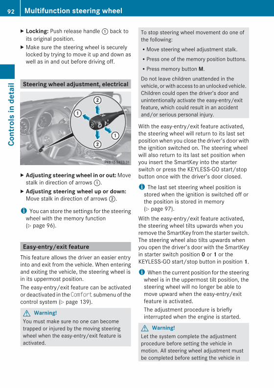
X Locking: Push release handle : back toits original position.
X Make sure the steering wheel is securelylocked by trying to move it up and down aswell as in and out before driving off.
Steering wheel adjustment, electrical
X Adjusting steering wheel in or out: Movestalk in direction of arrows :.
X Adjusting steering wheel up or down:Move stalk in direction of arrows ;.
i You can store the settings for the steeringwheel with the memory function(Y page 96).
Easy-entry/exit featureThis feature allows the driver an easier entryinto and exit from the vehicle. When enteringand exiting the vehicle, the steering wheel isin its uppermost position.The easy-entry/exit feature can be activatedor deactivated in the Comfort submenu of thecontrol system (Y page 139).
G Warning!You must make sure no one can becometrapped or injured by the moving steeringwheel when the easy-entry/exit feature isactivated.
To stop steering wheel movement do one ofthe following:RMove steering wheel adjustment stalk.RPress one of the memory position buttons.RPress memory button M.
Do not leave children unattended in thevehicle, or with access to an unlocked vehicle.Children could open the driver’s door andunintentionally activate the easy-entry/exitfeature, which could result in an accidentand/or serious personal injury.
With the easy-entry/exit feature activated,the steering wheel will return to its last setposition when you close the driver’s door withthe ignition switched on. The steering wheelwill also return to its last set position whenyou insert the SmartKey into the starterswitch or press the KEYLESS-GO start/stopbutton once with the driver’s door closed.
i The last set steering wheel position isstored when the ignition is switched off orthe position is stored in memory(Y page 97).
With the easy-entry/exit feature activated,the steering wheel tilts upwards when youremove the SmartKey from the starter switch.The steering wheel also tilts upwards whenyou open the driver’s door with the SmartKeyin starter switch position 0 or 1 or theKEYLESS-GO start/stop button in position 1.
i When the current position for the steeringwheel is in the uppermost tilt position, thesteering wheel will no longer be able tomove upward when the easy-entry/exitfeature is activated.The adjustment procedure is brieflyinterrupted when the engine is started.
G Warning!Let the system complete the adjustmentprocedure before setting the vehicle inmotion. All steering wheel adjustment mustbe completed before setting the vehicle in
92 Multifunction steering wheelCo
ntro
ls in
det
ail
X164_AKB; 5; 31, en-USd2ureepe, Version: 2.11.8.1
2009-09-11T12:30:16+02:00 - Seite 92

motion. Driving off with the steering wheelstill adjusting could cause the driver to losecontrol of the vehicle.
Crash-responsive exit aidWhen you open the driver’s door after anaccident has occurred, the steering columnmoves up. The position of the SmartKey in thestarter switch is insignificant. This functionfacilitates exiting as well as rescue of vehicleoccupants.The crash-responsive exit aid can only betriggered when the easy-entry/exit feature isactivated via the control system.
Heated steering wheelThe steering wheel heating warms up theleather area of the steering wheel.
X Switch on the ignition.X Switching on: Turn switch at the tip of the
stalk in direction of arrow :.Indicator lamp = comes on.
i The steering wheel heating may besuspended temporarily. However, indicatorlamp = remains on. The steering wheelheating is suspended when thetemperature of the vehicle interior is above86‡ (30†). It is also suspended when thetemperature of the steering wheel is above95‡ (35†).
When these conditions do not applyanymore, steering wheel heatingcontinues.
X Switching off: Turn switch at the tip ofstalk in direction of arrow ;.Indicator lamp = goes out.
i Indicator lamp = flashes or goes out incase of power surge or undervoltage or ifthe steering wheel heating malfunctions.
i The steering wheel heating switches offautomatically when you remove theSmartKey from the starter switch or, onvehicles with KEYLESS-GO, when youswitch off the ignition and open the driver’sdoor.
For more information on the steering wheel,see “Multifunction steering wheel”(Y page 125).
Mirrors
NotesAdjust the interior and exterior rear viewmirrors before driving so that you have a goodview of the road and traffic conditions.
Interior rear view mirrorX Adjust the interior rear view mirror
manually.
Mirrors 93
Cont
rols
in d
etai
l
X164_AKB; 5; 31, en-USd2ureepe, Version: 2.11.8.1
2009-09-11T12:30:16+02:00 - Seite 93
Z

Interior rear view mirror, antiglare position
X Tilt the mirror to the antiglare position bymoving lever : towards the windshield.The interior rear view mirror is dimmed.
Exterior rear view mirrors
G Warning!Exercise care when using the passenger-sideexterior rear view mirror. The mirror surfaceis convex (outwardly curved surface for awider field of view). Objects in mirror arecloser than they appear. Check your interiorrear view mirror and glance over yourshoulder before changing lanes.
X Switch on the ignition.X Press button : for the driver’s side
exterior rear view mirror or button = for
the passenger-side exterior rear viewmirror.The indicator lamp in the respective buttoncomes on for approximately 15 seconds.If you do not make adjustments to theselected exterior rear view mirror within15 seconds, the indicator lamp goes out.You will then have to select the desiredexterior rear view mirror again beforeadjustments can be made. Adjustmentscan only be made with the indicator lampfor the respective exterior rear view mirrorbutton illuminated.
X Press adjustment button ; up, down, leftor right according to the desired setting.
! If an exterior rear view mirror was forciblyhit from the front, manually snap it backinto place.
! Vehicle with power-folding exterior rearview mirrors:If an exterior rear view mirror housing isforcibly pushed forward (hit from the rear)or forcibly pushed rearward (hit from front),press fold button to fold mirrors in, thenpress fold button again to fold mirrors out.Do not force mirrors by hand as this maydamage the adjustment mechanism.The mirror housing is then properlypositioned and you can adjust the mirror inthe usual manner.
i At low ambient temperatures, the exteriorrear view mirrors will be heatedautomatically.
Auto-dimming rear view mirrorsThe exterior rear view mirror on the driver’sside and the interior rear view mirror willrespond automatically to glare when theignition is switched on and incoming lightfrom headlamps falls on the sensor in theinterior rear view mirror.
94 MirrorsCo
ntro
ls in
det
ail
X164_AKB; 5; 31, en-USd2ureepe, Version: 2.11.8.1
2009-09-11T12:30:16+02:00 - Seite 94

The rear view mirrors will not react if theautomatic transmission is set to reverse gearR or the interior lighting is switched on.
G Warning!The auto-dimming function does not react ifincoming light is not aimed directly at sensorsin the interior rear view mirror.The interior rear view mirror and the exteriorrear view mirror on the driver’s side do notreact, for example, when transporting cargowhich covers the rear window.Light hitting the mirror(s) at certain angles(incident light) could blind you. As a result,you may not be able to observe trafficconditions and could cause an accident.
Exterior rear view mirror parking position
For more convenient parking, you can set thepassenger-side exterior rear view mirror sothat you can see the rear wheel and the roadcurb.
Setting and storing the parking position
X Switch on the ignition.X Press button =, to select the passenger-
side exterior rear view mirror.
X Shift the automatic transmission intoreverse gear R.The passenger-side exterior rear viewmirror moves to the preset parkingposition.
X Adjust the passenger-side exterior rearview mirror with adjustment button ; sothat you see the rear wheel and the roadcurb.The exterior rear view mirror parkingposition is stored.
Calling up the parking positionX Switch on the ignition.X Press button =, to select the passenger-
side exterior rear view mirror.X Shift the automatic transmission into
reverse gear R.The passenger-side exterior rear viewmirror moves to the stored parkingposition.
The passenger-side exterior rear view mirrorreturns to its previously stored drivingpositionR10 seconds after you have put the gear
selector lever out of reverse gear RRimmediately once your vehicle exceeds a
speed of approximately 6 mph (10 km/h)Rimmediately when you press button : to
select the driver’s side exterior rear viewmirror
Power-folding exterior rear view mirrors
! Before you drive the vehicle through anautomatic car wash, fold in the exterior rearview mirrors. Otherwise they may getdamaged.
Folding in and out automatically The function must be activated in theConvenience submenu (Y page 140).
Mirrors 95
Cont
rols
in d
etai
l
X164_AKB; 5; 31, en-USd2ureepe, Version: 2.11.8.1
2009-09-11T12:30:16+02:00 - Seite 95
Z
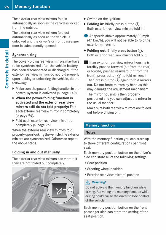
The exterior rear view mirrors fold inautomatically as soon as the vehicle is lockedfrom the outside.The exterior rear view mirrors fold outautomatically as soon as the vehicle isunlocked and the driver’s or front passengerdoor is subsequently opened.
SynchronizingThe power-folding rear view mirrors may haveto be synchronized after the vehicle batteryhas been disconnected or discharged. If theexterior rear view mirrors do not fold properlyupon locking or unlocking the vehicle, do thefollowing:X Make sure the power-folding function in the
control system is activated (Y page 140).X When the power-folding function is
activated and the exterior rear view mirrors still do not fold properly: Foldeach exterior rear view mirror in completely(Y page 96).
X Fold each exterior rear view mirror outcompletely (Y page 96).
When the exterior rear view mirrors foldproperly upon locking the vehicle, the exteriormirrors are synchronized. Otherwise repeatthe above steps.
Folding in and out manuallyThe exterior rear view mirrors can vibrate ifthey are not folded out completely.
X Switch on the ignition.X Folding in: Briefly press button :.
Both exterior rear view mirrors fold in.
i At speeds above approximately 30 mph(47 km/h), you will not be able to fold theexterior mirrors in.
X Folding out: Briefly press button :.Both exterior rear view mirrors fold out.
! If an exterior rear view mirror housing isforcibly pushed forward (hit from the rear)or forcibly pushed rearward (hit from thefront), press button : to fold mirrors in.Then press button : again to fold mirrorsout. Do not force mirrors by hand as thismay damage the adjustment mechanism.The mirror housing is then properlypositioned and you can adjust the mirror inthe usual manner.Make sure both rear view mirrors are foldedout before driving off.
Memory function
NotesWith the memory function you can store upto three different configurations per frontseat.Each memory position button on the driver’sside can store all of the following settings:RSeat positionRSteering wheel positionRExterior rear view mirrors’ position
G Warning!Do not activate the memory function whiledriving. Activating the memory function whiledriving could cause the driver to lose controlof the vehicle.
Each memory position button on the frontpassenger side can store the setting of theseat position.
96 Memory functionCo
ntro
ls in
det
ail
X164_AKB; 5; 31, en-USd2ureepe, Version: 2.11.8.1
2009-09-11T12:30:16+02:00 - Seite 96

Storing positions into memoryX Adjust the seats.X On the driver’s side, also adjust the
steering wheel and exterior rear viewmirrors to the desired positions.
X Press memory button M once and within3 seconds press memory position button1, 2 or 3.When the settings are stored to theselected position, an acknowledgementsignal sounds.
Recalling positions from memoryX Press and hold desired memory position
button 1, 2 or 3 until the seat has movedto the stored position completely. On thedriver’s side, also wait for the steeringwheel and exterior rear view mirrors tomove to the stored position.
i Releasing the memory position buttonstops movement to the stored positionsimmediately.
Lighting
Notesi If you drive in countries with left-hand
driving, you must have the headlamps
modified for symmetrical low beams.Relevant information can be obtained atany authorized Mercedes-Benz Center.
i Vehicles equipped with active Bi-Xenonheadlamps:The active Bi-Xenon headlamps increaseusable illumination over conventionalheadlamps because they follow thecurvature of the road ahead. The beams ofthe active Bi-Xenon headlamps shift toeither side according to the vehicle’ssteering angle and speed.
Exterior lamp switch
1 W Standing lamps, left2 X Standing lamps, right3 $ Off
Daytime running lamp mode4 Ã Automatic headlamp mode
Daytime running lamp mode5 T Parking lamps6
6 L Low-beam headlamps or high-beamheadlamps
7 R Vehicles without front fog lamps:Rear fog lamp
7 N Vehicles with front fog lamps: Frontfog lamps
8 R Vehicles with front fog lamps: Rearfog lamp
6 When the parking lamps are on, the tail lamps, the license plate lamps, the side marker lamps, and theinstrument cluster illumination are also on.
Lighting 97
Cont
rols
in d
etai
l
X164_AKB; 5; 31, en-USd2ureepe, Version: 2.11.8.1
2009-09-11T12:30:16+02:00 - Seite 97
Z

i The exterior lamps (except standinglamps or parking lamps) go outautomatically when you remove theSmartKey from the starter switch or openthe driver’s door with the ignition switchedoff.When the parking lamps or the rear foglamp are switched on and you remove theSmartKey from the starter switch and openthe driver’s door, an acoustic signalsounds.In addition the message Switch Off Lights appears in the multifunctiondisplay.Switch off the parking lamps or the rear foglamp manually.
! Failure to switch off the parking lampswhen leaving the vehicle may result in adischarged battery.
i Vehicles without front fog lamps: Forbetter detection of the vehicle, the LEDdaytime running lamps are dimmed toparking lamp level when the low-beamheadlamps are switched on.
Low-beam headlamps The low-beam headlamps can be switched onand off with the exterior lamp switch.X Switch on the ignition.X Switching on: Turn the exterior lamp
switch to position L.The following lamps come on:RLow-beam headlampsRParking lamps6
RGreen indicator lamp L in theinstrument cluster
X Switching off: Turn the exterior lampswitch to position $.
Automatic headlamp mode
G Warning!If the exterior lamp switch is set to Ã, theheadlamps will not automatically come onunder foggy conditions.To minimize risk to you and to others, activateheadlamps by turning exterior lamp switch toL when driving or when traffic and/orambient lighting conditions require you to doso.In low ambient lighting conditions, only switchfrom position à to L with the vehicleat a standstill in a safe location. Switchingfrom à to L will briefly switch off theheadlamps. Doing so while driving in lowambient lighting conditions may result in anaccident.The automatic headlamp feature is only an aidto the driver. The driver is responsible for theoperation of the vehicle’s lights at all times.
X Switching on: Turn the exterior lampswitch to position Ã.
When ambient light is low: When theSmartKey is in starter switch position 1 orwhen the KEYLESS-GO start/stop button hasbeen pressed once, the parking lamps6 comeon automatically.When the engine is running, the low-beamheadlamps come on additionally.When ambient light is bright: When theSmartKey is in starter switch position 1 orwhen the KEYLESS-GO start/stop button hasbeen pressed once, all lamps are off.When the engine is running, the daytimerunning lamps7 come on automatically.When the low-beam headlamps are switchedon, the green indicator lamp L in theinstrument cluster comes on.Once the low-beam headlamps are on, thehigh-beam headlamps are also available.
6 When the parking lamps are on, the tail lamps, the license plate lamps, the side marker lamps, and theinstrument cluster illumination are also on.
7 USA only: The daytime running lamp mode must be activated via the control system.
98 LightingCo
ntro
ls in
det
ail
X164_AKB; 5; 31, en-USd2ureepe, Version: 2.11.8.1
2009-09-11T12:30:16+02:00 - Seite 98

Daytime running lamp mode In Canada, the daytime running lamp mode ismandatory and therefore in a constant mode.In the USA, the daytime running lamp modeis deactivated by default.X Activate the daytime running lamp mode
using the control system, see “Switchingdaytime running lamp mode on or off (USAonly)” (Y page 136).
X Turn the exterior lamp switch to position$ or Ã.When the engine is running and theambient light is bright, the daytime runninglamps come on.In low ambient lighting conditions, thefollowing lamps will come on additionally:RLow-beam headlampsRParking lamps6
Rgreen indicator lamp L in theinstrument cluster
You can only switch on the high-beamheadlamps when the low-beam headlampsare on.The high-beam flasher is available at all times.
Canada onlyWhen the engine is running, and youRshift from a driving position to park
position P with the vehicle at a standstill orthe parking brake is engaged, daytimerunning lamps or the low-beam headlampswill go out with a delay of 3 minutesRturn the exterior lamp switch to positionT, the daytime running lamps and theparking lamps6 come on in bright ambientlighting conditions.Rturn the exterior lamp switch to positionL, the manual headlamp mode haspriority over the daytime running lampmode
The corresponding exterior lamps come on(Y page 97).
USA onlyWhen the engine is running, and you turn theexterior lamp switch to position T orL, the manual headlamp mode haspriority over the daytime running lamp mode.The corresponding exterior lamps come on(Y page 97).
Fog lamps Fog lamps cannot be switched on with theexterior lamp switch in position à or$.
G Warning!In low ambient lighting or foggy conditions,only switch from position à to L withthe vehicle at a standstill in a safe location.Switching from à to L will brieflyswitch off the headlamps. Doing so whiledriving in low ambient lighting conditions mayresult in an accident.
Front fog lamps will operate with the parkinglamps and/or the low-beam headlamps on.The rear fog lamp can only be switched onwith the exterior lamp switch in positionL. Fog lamps should only be used inconjunction with low-beam headlamps.Consult your State or Province Motor VehicleRegulations regarding permissible lampoperation.X Switch on the ignition.X Turn the exterior lamp switch to positionT or L (Y page 97).
6 When the parking lamps are on, the tail lamps, the license plate lamps, the side marker lamps, and theinstrument cluster illumination are also on.
Lighting 99
Cont
rols
in d
etai
l
X164_AKB; 5; 31, en-USd2ureepe, Version: 2.11.8.1
2009-09-11T12:30:16+02:00 - Seite 99
Z

Vehicles with front fog lampsX Switching on front fog lamps: Pull out the
exterior lamp switch to first stop.The green indicator lamp N in theexterior lamp switch comes on.
X Switching on rear fog lamp: Pull out theexterior lamp switch to second stop.The rear fog lamp, the front fog lamps, thegreen and the yellow indicator lamp Rin the exterior lamp switch come on.
X Switching off front fog lamps/rear fog lamp: Push in the exterior lamp switch toits stop.
Vehicles without front fog lampsX Switching on rear fog lamp: Pull out the
exterior lamp switch to its stop.The rear fog lamp and the yellow indicatorlamp R in the exterior lamp switchcome on.
X Switching off rear fog lamp: Push in theexterior lamp switch to its stop.
Locator lighting and night security illumination Locator lighting and night securityillumination are described in the “Controlsystem” section, see “Switching locatorlighting on or off” (Y page 136) and“Switching night security illumination(Headlamps delayed shut-off feature) on oroff” (Y page 137).
Combination switch
Turn signals X Press the combination switch in direction
of arrow ; or ?.The corresponding turn signal indicatorlamp ! or # in the instrumentcluster flashes.
The combination switch resets automaticallyafter major steering wheel movements.
i To signal minor directional changes suchas changing lanes, press the combinationswitch only to point of resistance andrelease. The corresponding turn signallamps will flash three times.
High beam X Turn the exterior lamp switch to positionL (Y page 97).
X Switching on: Push the combinationswitch in direction of arrow :.The high-beam headlamp indicator lampK in the instrument cluster comes on.
X Switching off: Pull the combination switchin direction of arrow = to its originalposition.
i Also note the information on high-beamheadlamps with activated automaticheadlamp mode (Y page 98) or the daytimerunning lamp mode (Y page 99).
100 LightingCo
ntro
ls in
det
ail
X164_AKB; 5; 31, en-USd2ureepe, Version: 2.11.8.1
2009-09-11T12:30:16+02:00 - Seite 100

High-beam flasher X Switching on: Pull the combination switch
briefly in direction of arrow =.
Hazard warning flasherThe hazard warning flasher can be switchedon at all times, even with the SmartKeyremoved from the starter switch.The hazard warning flasher comes onautomatically when an air bag deploys.
X Switching on: Press hazard warningflasher switch :.All turn signal lamps are flashing.
i With the hazard warning flasher activatedand the combination switch set for eitherleft or right turn, only the respective left orright turn signals will operate when theignition is switched on.
X Switching off: Press hazard warningflasher switch : again.
i If the hazard warning flasher has beenactivated automatically, press hazardwarning flasher switch : to switch it off.
Headlamp cleaning systemThe headlamps will be cleaned with a high-pressure water jet automatically when theengine is running and you haveRswitched on the headlamps
andRthe windshield wipers have wiped the
windshield with washer fluid five timesThe counter resets when you switch off theheadlamps.For information on filling up the washerreservoir, see “Washer system and headlampcleaning system” (Y page 232).
Interior lighting in the front
: p Left front reading lamp on/off; v Rear interior lighting on/off= ~ Automatic control on/off? c Front interior lighting on/off A p Right front reading lamp on/offB Front interior lightingC Front reading lamps D Front interior lighting
Automatic control X Activating: Press button ~.
Button ~ disengages and sits flush withthe other buttons.The interior lighting comes on when you
Lighting 101
Cont
rols
in d
etai
l
X164_AKB; 5; 31, en-USd2ureepe, Version: 2.11.8.1
2009-09-11T12:30:16+02:00 - Seite 101
Z

Runlock the vehicleRremove the SmartKey from the starter
switch (Interior Lighting Delayed Shut-off must be switched on(Y page 138))Ropen a doorRopen the tailgate
The interior lighting goes out after a shorttime.
i If a door remains open, the interior lampsgo out automatically after approximately5 minutes when the SmartKey is removedor in starter switch position 0.
X Deactivating: Press button ~.Button ~ engages.
Manual control ! An interior lamp switched on manually
does not go out automatically.Leaving an interior lamp switched on for anextended period of time with the engineturned off could result in a dischargedbattery.
X Switching front interior lighting on/off: Press switch c.
X Switching rear interior lighting on/off:Press switch v.
X Switching front reading lamps on/off:Press respective switch p.
Ambient lightingThe brightness of the ambient lighting C isadjusted via the “Control system”(Y page 137).
Emergency lighting The interior lighting comes on automaticallyif the vehicle is involved in an accident.
Switching off: X Press button ~.orX Press hazard warning flasher switch
(Y page 101).orX Unlock the vehicle with the SmartKey.
Interior lighting in the rear! An interior lamp switched on manually
does not go out automatically.Leaving an interior lamp switched on for anextended period of time with the engineturned off could result in a dischargedbattery.
Second-row reading lamps
X Switching rear reading lamps on/off:Press second-row reading lamp : whereindicated by the arrow.
102 LightingCo
ntro
ls in
det
ail
X164_AKB; 5; 31, en-USd2ureepe, Version: 2.11.8.1
2009-09-11T12:30:16+02:00 - Seite 102

Third-row reading lamps and interior lighting
: p Right third-row reading lamp on/off; p Left third-row reading lamp on/off= Left third-row reading lamp? Rear interior lightingA Right third-row reading lamp
i The rear interior lighting is switched onand off using the button on the frontoverhead control panel (Y page 101).
Wipers
Notes! Do not operate the wipers when the
windshield/rear window is dry. Dust thataccumulates on a windshield/rear windowmight scratch the glass and/or damage thewiper blades when wiping occurs on a drywindshield/rear window. If it is necessaryto operate the wipers in dry weatherconditions, always operate the wipers withwasher fluid.
Windshield wipersX Observe notes on page (Y page 103).
Switching on/off
Combination switch1 $ Windshield wipers off2Ä Slow intermittent wiping8
3Å Fast intermittent wiping9
4 ° Slow continuous wiping5 ¯ Fast continuous wipingB í Single wipe/ î Wiping with
washer fluid
X Switch on the ignition.X Turn the combination switch to the desired
position, depending on the intensity of therain.
Intermittent wiping Only switch on intermittent wiping under wetweather conditions or in the presence ofprecipitation.When you select intermittent wiping, the rainsensor is activated. The rain sensor sets asuitable wiping interval depending on thewetness of the sensor surface automatically.
! Do not leave windshield wipers on anintermittent setting when the vehicle istaken to an automatic car wash or duringwindshield cleaning. Windshield wipers willoperate in the presence of water sprayedon the windshield, and windshield wipersmay be damaged as a result.
8 Rain sensor operation with low sensitivity.9 Rain sensor operation with high sensitivity.
Wipers 103
Cont
rols
in d
etai
l
X164_AKB; 5; 31, en-USd2ureepe, Version: 2.11.8.1
2009-09-11T12:30:16+02:00 - Seite 103
Z

! If you have set intermittent wiping, dirt onthe surface of the rain sensor or opticaleffects may cause the windshield wipers towipe in an undesired fashion. This couldthen damage the windshield wiper bladesor scratch the windshield. You shouldtherefore switch off the windshield wiperswhen weather conditions are dry.
X Turn the combination switch to positionÄ or Å.After the initial wipe, pauses betweenwipes are controlled by the rain sensorautomatically.
Intermittent wiping is interrupted when thevehicle is at a standstill and a front door isopened. This protects persons getting into orout of the vehicle from being sprayed.Intermittent wiping will be continued when alldoors are closed andRthe automatic transmission is in drive
position D or reverse gear RorRthe wiper setting is changed using the
combination switch
Single wipeX Press the combination switch briefly in
direction of arrow B to the resistancepoint.The windshield wipers wipe one timewithout washer fluid.
Wiping with washer fluidX Press the combination switch in direction
of arrow B past the resistance point.The windshield wipers operate with washerfluid.
i To prevent smears on the windshield ornoisy/chattering wiper blades, wipe withwasher fluid every now and then even whenit is raining.
For information on filling up the washerreservoir, see “Washer system and headlampcleaning system” (Y page 232).For information on cleaning the headlampswith washer fluid, see “Headlamp cleaningsystem” (Y page 101).
Rear window wiper/washerX Observe notes on page (Y page 103).The rear window wiper engages automaticallywhen the automatic transmission is shiftedinto reverse gear R with the windshield wipersswitched on.
Combination switch: Rear window wiper switch2 Wiping rear window with washer fluid3 Intermittent wiping4 Rear window wiper off5 Wiping rear window with washer fluid
X Switch on the ignition.X Turn rear window wiper switch : to the
desired position.
Rear window wiper indicator B appears inthe lower multifunction display when the rearwindow wiper is activated.
104 WipersCo
ntro
ls in
det
ail
X164_AKB; 5; 31, en-USd2ureepe, Version: 2.11.8.1
2009-09-11T12:30:16+02:00 - Seite 104

For information on filling up the washerreservoir, see “Washer system and headlampcleaning system” (Y page 232).
Problems with wipers! If anything blocks the wipers (leaves,
snow, etc.), switch them off immediately.For safety reasons, do the following beforeattempting to remove any blockage:RStop the vehicle in a safe location.RRemove the SmartKey from the starter
switch.orRTurn off the engine by pressing the
KEYLESS-GO start/stop button andopen the driver’s door (with the driver’sdoor open, starter switch is in position0, same as with SmartKey removed fromstarter switch).REngage the parking brake.RRemove blockage.RTurn the wipers on again.If the windshield wipers fail to function atall with the combination switch in positionÄ or Å,Rset the combination switch to the next
higher wiper speedRhave the windshield wipers checked at
the nearest authorized Mercedes-BenzCenter
Power windows
Opening and closingThe door windows and the hinged quarterwindows are opened and closed electrically.The switches for all door windows and thehinged quarter windows are located on thedriver’s door control panel. The switches forthe respective door windows are located onthe front passenger door and the rear doors.
The hinged quarter windows can be operatedfrom the driver’s seat only.
i Operating the rear door windows fromthe rear is not possible when you activatethe override switch (Y page 60).
G Observe Safety notes, see page 55.
G Warning!When opening or closing the windows, makesure there is no danger of anyone beingharmed by the opening/closing procedure.The door windows are equipped with theexpress operation and automatic reversalfunction. If in express operation mode a doorwindow encounters an obstruction thatblocks its path, the automatic reversalfunction will stop the door window and openit slightly.The door windows operate differently whenthe switch is pulled and held. See the “Closingwhen a door window is blocked” section inthis chapter for details.The closing of a door window can beimmediately halted by releasing the switch or,if the switch was pulled past the resistancepoint and released, by either pressing orpulling the respective switch.The closing of the hinged quarter windows canbe immediately halted by pressing or pullingthe switch.If a window encounters an obstruction thatblocks its path in a circumstance where youare closing the windows by pressing andholding button & on the SmartKey or bypressing and holding the lock button (vehicleswith KEYLESS-GO) on an outside door handle,the automatic reversal function will notoperate.Activate the override switch when childrenare riding in the back seats of the vehicle. Thechildren may otherwise injure themselves,e.g. by becoming trapped in the windowopening.
Power windows 105
Cont
rols
in d
etai
l
X164_AKB; 5; 31, en-USd2ureepe, Version: 2.11.8.1
2009-09-11T12:30:16+02:00 - Seite 105
Z

G Warning!Do not keep any part of your body up againstthe window pane when opening a window. Thedownward motion of the pane may pull thatpart of your body down between the windowpane and the door frame and trap it there. Ifthere is a risk of entrapment, release theswitch and pull it to close the window.
i You can also open or close the windowsusing the SmartKey, see “Summer openingfeature” (Y page 107) and “Convenienceclosing feature” (Y page 107).
i After switching off the ignition orremoving the SmartKey from the starterswitch, you can operate the windows untilyou open the driver’s or front passengerdoor. If no door was opened you canoperate the windows for up to 5 minutes.
Door windows X Switch on the ignition.X Opening/closing: Press or pull and hold
switch : to ? to the resistance point.The corresponding window movesdownward or upward until you release theswitch.
X Express operation: Press or pullswitch : to ? past the resistance pointand release.The corresponding window opens or closescompletely.
X Stopping during express operation:Press or pull the respective switch again.
Closing when a door window is blockedG Warning!Make sure that nobody can become trappedand be seriously or even fatally injured whenclosing a door window with greater force orwithout automatic reversal function.
If the upward movement of a door window isblocked during the closing procedure, thedoor window will stop and open slightly.X Immediately after the door window has
stopped because it was blocked, pull andhold the respective switch upward until thedoor window is fully closed.The door window closes with greater force.
If the door window is blocked again and opensslightly:X Immediately after the door window was
blocked, pull and hold the respectiveswitch upward until the door window is fullyclosed.The door window closes without automaticreversal function.
G Warning!Pulling and holding the switch to close thedoor window immediately after it had beenblocked two times will cause the door windowto close without any reversal function for aslong as you hold the switch.
Hinged quarter windows X Switch on the ignition.X Opening: Press switch A and release.
Both hinged quarter windows opencompletely.
106 Power windowsCo
ntro
ls in
det
ail
X164_AKB; 5; 31, en-USd2ureepe, Version: 2.11.8.1
2009-09-11T12:30:16+02:00 - Seite 106

X Closing: Pull switch A and release.Both hinged quarter windows closecompletely.
i When the obstruction sensor detects thata hinged quarter windows is blocked duringthe closing process, they will stop and openslightly.
X Halting closing process: Press or pullswitch A once more during the closingprocess.The hinged quarter windows will stop andopen completely.
i For your safety, the hinged quarterwindows cannot be opened again until4 seconds have passed.
Synchronizing door windowsThe door windows must be synchronized afterthe battery has been disconnected or if thedoor windows cannot be fully closed (expressoperation).Each door window must be synchronizedseparately.X Close all doors.X Switch on the ignition.X Pull and hold switch :, ;, = or ?
(Y page 106) until the respective doorwindow is closed.The door window opens again slightly.
X Pull and hold the respective switch oncemore immediately until the door window isclosed completely.
X Hold the respective switch forapproximately 1 second.The door window is synchronized.
Summer opening featureWhen the weather is warm, you can ventilatethe vehicle before driving off bysimultaneouslyRopening the door windowsRopening the hinged quarter windowsRopening the tilt/sliding sunroofRswitching on the seat ventilation for the
driver’s seatThe summer opening feature can only beactivated via the remote control of theSmartKey. The SmartKey must be in closeproximity to the driver’s outside door handle.X Aim the transmitter eye of the SmartKey at
the driver’s outside door handle.X Press and hold button % on the
SmartKey until the windows and the tilt/sliding sunroof have reached the desiredposition.The vehicle unlocks.
X Release button % on the SmartKey tointerrupt the opening procedure.
Convenience closing featureWhen locking the vehicle, you cansimultaneously closeRthe door windowsRthe hinged quarter windowsRthe tilt/sliding sunroof
G Warning!When closing the windows and the tilt/slidingsunroof, make sure there is no danger ofanyone being harmed by the closingprocedure.If potential danger exists, proceed as follows:RRelease button & to stop the closing
procedure. To open, press and hold button%. To continue the closing procedureafter making sure that there is no danger of
Power windows 107
Cont
rols
in d
etai
l
X164_AKB; 5; 31, en-USd2ureepe, Version: 2.11.8.1
2009-09-11T12:30:16+02:00 - Seite 107
Z

anyone being harmed by the closingprocedure, press and hold button &.
Vehicles with KEYLESS-GO:RRelease the lock button on the outside door
handle to stop the closing procedure.RImmediately pull on the same outside door
handle and hold firmly. The windows andthe tilt/sliding sunroof will open for as longas the door handle is held but the door notopened.
With SmartKeyThe SmartKey must be in close proximity tothe driver’s outside door handle.X Aim transmitter eye of the SmartKey at the
driver’s outside door handle.X Press and hold button & on the
SmartKey until the windows and the tilt/sliding sunroof are closed completely.The vehicle locks.
X Release button & on the SmartKey tointerrupt the closing procedure.
With KEYLESS-GOThe SmartKey with KEYLESS-GO must belocated outside the vehicle withinapproximately 3 ft (1 m) of a door.X Close all doors.X Press and hold the lock button on an
outside door handle (Y page 73) until thedoor windows and the tilt/sliding sunroofare closed completely.
X Release the lock button on the outside doorhandle to interrupt the closing procedure.
Driving and parking
Safety notes
G Warning!Make sure absolutely no objects areobstructing the pedals’ range of movement.Keep the driver’s footwell clear of allobstacles. If there are any floormats orcarpets in the footwell, make sure the pedalsstill have sufficient clearance.During sudden driving or braking maneuversthe objects could get caught between thepedals. You could then no longer brake oraccelerate. This could lead to accidents andinjury.
G Warning!With the engine not running, there is no powerassistance for the brake and steeringsystems. In this case, it is important to keepin mind that a considerably higher degree ofeffort is necessary to brake and steer thevehicle. Adapt your driving accordingly.
Starting the engine
G Warning!Inhalation of exhaust gas is hazardous to yourhealth. All exhaust gas contains carbonmonoxide (CO), and inhaling it can causeunconsciousness and possible death.Do not run the engine in confined areas (suchas a garage) which are not properly ventilated.If you think that exhaust gas fumes areentering the vehicle while driving, have thecause determined and correctedimmediately. If you must drive under theseconditions, drive only with at least onewindow fully open at all times.
108 Driving and parkingCo
ntro
ls in
det
ail
X164_AKB; 5; 31, en-USd2ureepe, Version: 2.11.8.1
2009-09-11T12:30:16+02:00 - Seite 108

Automatic transmission
Gearshift pattern for automatic transmission: Button for selecting park position Pj Park positionk Reverse geari Neutral positionh Drive position
For more information on how to operate thegear selector lever, see “Automatictransmission” (Y page 114).X Make sure the automatic transmission is in
park position P.The transmission position indicator in themultifunction display should be on P(Y page 116).
With SmartKey X Do not depress the accelerator pedal.X Gasoline engine: Turn the SmartKey in the
starter switch to position 3 (Y page 80) andrelease it.The engine starts automatically.
X Diesel engine: Turn the SmartKey in thestarter switch to position 2 (Y page 80).Preglow indicator lamp % in theinstrument cluster comes on.
X As soon as preglow indicator lamp %goes out, turn the SmartKey in the starterswitch to position 3 and release it.The engine starts automatically.
i If the engine is at operating temperature,preglow indicator lamp % may not stay
on and you can start the engine withoutpreglowing.
With KEYLESS-GO
G Warning!As long as the SmartKey is in your vehicle, thevehicle can be started. Therefore, never leavechildren unattended in the vehicle, as theycould otherwise accidentally start the engine.When leaving the vehicle, always take theSmartKey with you and lock the vehicle. Donot leave children unattended in the vehicle,or with access to an unlocked vehicle. Achild’s unsupervised access to a vehicle couldresult in an accident and/or serious personalinjury.
You can start your vehicle without theSmartKey in the starter switch using theKEYLESS-GO start/stop button.The SmartKey must be located in the vehicle.
KEYLESS-GO start/stop button: USA only; Canada only
X Make sure the KEYLESS-GO start/stopbutton is inserted in the starter switch(Y page 80).
i To start the engine with the SmartKeyinstead of the KEYLESS-GO function,remove the KEYLESS-GO start/stop buttonfrom the starter switch. Proceed asdescribed in “With SmartKey”(Y page 109).
Driving and parking 109
Cont
rols
in d
etai
l
X164_AKB; 5; 31, en-USd2ureepe, Version: 2.11.8.1
2009-09-11T12:30:16+02:00 - Seite 109
Z

X Depress the brake pedal during the startingprocedure.
X Do not depress the accelerator pedal.X Gasoline engine: Press the KEYLESS-GO
start/stop button once.The engine starts automatically.
X Diesel engine: Press the KEYLESS-GOstart/stop button once.The engine preglows and startsautomatically.
i If the engine is at operating temperature,the time the engine needs to preglow isreduced.
Starting difficulties ! Remember that extended starting
attempts can drain the battery.
The engine does not start. You can hear the starter.There could be a malfunction in the engineelectronics or in the fuel supply system.Carry out the following steps:X If you are starting the engine with the
SmartKey: Turn the SmartKey in the starterswitch to position 0 and repeat the startingprocedure.
X If you are starting the engine with KEYLESS-GO: Close any doors that may be open toallow for better detection of the SmartKey.
orX Remove the KEYLESS-GO start/stop
button from the starter switch.X Start the engine with the SmartKey as radio
signals from another source may beinterfering with the KEYLESS-GO function.
X Repeat the starting procedure.
If the engine does not start after severalstarting attempts:X Contact an authorized Mercedes-Benz
Center or call Roadside Assistance.
The engine does not start. You cannot hear the starter.The battery may not be charged sufficiently.X Get a jump start (Y page 350).
If the engine will not start despite a jumpstart:X Contact an authorized Mercedes-Benz
Center or call Roadside Assistance.The starter has been exposed to excessivetemperatures.X Let the starter cool for about 2 minutes.X Repeat the starting procedure.
If the engine does not start after severalstarting attempts:X Contact an authorized Mercedes-Benz
Center or call Roadside Assistance.
Driving off
G Warning!On slippery road surfaces, never downshift inorder to obtain braking action. This couldresult in drive wheel slip and reduced vehiclecontrol. Your vehicle’s ABS will not preventthis type of loss of control.
! Do not run a cold engine at high enginespeeds. Running a cold engine at highengine speeds may shorten the service lifeof the engine. This is not covered by theMercedes-Benz Limited Warranty.
! If an acoustic warning sounds and themessage Release Parking Brakeappears in the multifunction display whendriving off, you have forgotten to releasethe parking brake.Release the parking brake.
! Avoid spinning of a drive wheel. This maycause serious damage to the drivetrainwhich is not covered by the Mercedes-BenzLimited Warranty.
110 Driving and parkingCo
ntro
ls in
det
ail
X164_AKB; 5; 31, en-USd2ureepe, Version: 2.11.8.1
2009-09-11T12:30:16+02:00 - Seite 110

! Simultaneously depressing theaccelerator pedal and applying the brakesreduces engine performance and causespremature brake and drivetrain wear whichis not covered by the Mercedes-BenzLimited Warranty.
i Once the vehicle is in motion, theautomatic central locking function engagesand the locking knobs in the doors movedown.The automatic central locking function canbe switched off (Y page 138).
Automatic transmission
G Warning!It is dangerous to shift the automatictransmission out of park position P or neutralposition N if the engine speed is higher thanidle speed. If your foot is not firmly on thebrake pedal, the vehicle could acceleratequickly forward or in reverse. You could losecontrol of the vehicle and hit someone orsomething. Only shift into gear when theengine is idling normally and when your rightfoot is firmly on the brake pedal.
! Only shift the automatic transmission intoreverse gear R or park position P when thevehicle is stopped. Otherwise theautomatic transmission could be damaged.
X Depress the brake pedal.The gear selector lever can now be used.
X Shift the automatic transmission into driveposition D or reverse gear R.
i Shifting the automatic transmission out ofpark position P is only possible with thebrake pedal depressed.Without the brake pedal depressed, thegear selector lever can be moved up ordown. However, the parking pawl remainsengaged, not allowing shifting to occur.
X Wait for the gear selection process tocomplete before setting the vehicle inmotion.
X If engaged, release the parking brake.X Release the brake pedal.X Carefully depress the accelerator pedal.After a cold start, the automatic transmissionshifts at a higher engine speed. This allowsthe catalytic converter (gasoline engine) orthe oxidation catalyst (diesel engine) to reachits operating temperature earlier.For more information on driving, see “Drivinginstructions” (Y page 259).For information on off-road driving, see “Off-road driving” (Y page 262).
Problems while driving
The engine runs erratically and misfiresRGasoline engine: An ignition cable may be
damaged.RThe engine electronics may not be
operating properly.RGasoline engine: Unburned gasoline may
have entered the catalytic converter anddamaged it.
X Give very little gas.X Have the problem checked at an authorized
Mercedes-Benz Center as soon as possible.
The coolant temperature is above 248‡ (120†)The coolant is too hot and is no longer coolingthe engine.X Stop the vehicle in a safe location as soon
as possible.X Turn off the engine immediately.X Allow the engine and coolant to cool off.X Check the coolant level and add coolant if
necessary (Y page 231).
Driving and parking 111
Cont
rols
in d
etai
l
X164_AKB; 5; 31, en-USd2ureepe, Version: 2.11.8.1
2009-09-11T12:30:16+02:00 - Seite 111
Z

In case of accident If the vehicle is leaking fuel:X Do not start the engine under any
circumstances.X Exit the vehicle at a safe distance from the
roadway.X Notify local fire and/or police authorities.
If the extent of the damage cannot bedetermined:X Contact an authorized Mercedes-Benz
Center or call Roadside Assistance.
If no damage on major assemblies, fuelsystem, and engine mount can bedetermined:X Start the engine in the usual manner.
Parking
G Warning!Do not park this vehicle in areas wherecombustible materials such as grass, hay orleaves can come into contact with the hotexhaust system. These materials could beignited and cause a vehicle fire.Vehicle movement may result in seriouspersonal injury or damage to the vehicle orvehicle drivetrain. Therefore, always do thefollowing before turning off the engine andleaving the vehicle:RKeep right foot on the brake pedal.REngage the parking brake.RShift the automatic transmission into park
position P.RSlowly release the brake pedal.RWhen parked on an incline, always turn the
front wheels towards the road curb.RTurn the SmartKey in the starter switch to
position 0 and remove the SmartKey from
the starter switch, or press the KEYLESS-GO start/stop button.RTake the SmartKey with you and lock the
vehicle when leaving.
Parking brake
G Warning!Engaging the parking brake while the vehicleis in motion can cause the rear wheels to lockup. You could lose control of the vehicle andcause an accident. In addition, the vehicle’sbrake lights do not light up when the parkingbrake is engaged.
G Warning!When leaving the vehicle, always remove theSmartKey from the starter switch, take it withyou, and lock the vehicle. Do not leavechildren unattended in the vehicle, or withaccess to an unlocked vehicle. Children couldrelease the parking brake and/or shift theautomatic transmission out of park positionP, either of which could result in an accidentand/or serious personal injury.
X Releasing: Pull on release handle :.When the ignition is switched on or theengine is running, the brake warning lamp$ (USA only) or J (Canada only) inthe instrument cluster goes out.
X Engaging: Step on parking brakepedal ; firmly.When the engine is running, the brakewarning lamp $ (USA only) or J
112 Driving and parkingCo
ntro
ls in
det
ail
X164_AKB; 5; 31, en-USd2ureepe, Version: 2.11.8.1
2009-09-11T12:30:16+02:00 - Seite 112

(Canada only) in the instrument clustercomes on.
Turning off the engine
G Warning!Do not turn off the engine before the vehiclehas come to a complete stop. With the enginenot running, there is no power assistance forthe brake and steering systems. In this case,it is important to keep in mind that aconsiderably higher degree of effort isnecessary to brake and steer the vehicle.
i If the engine cannot be turned off asdescribed, see “Emergency engineshutdown” (Y page 357).
X Shift the automatic transmission into parkposition P.
X Engage the parking brake.
i Always engage the parking brake inaddition to shifting the automatictransmission into park position P.
i Observe instructions if you want theautomatic transmission to remain inneutral position N, see “Remaining inneutral position N” (Y page 115).
With SmartKey X Turn the SmartKey in the starter switch to
position 0.X Remove the SmartKey from the starter
switch.When you turn off the engine using theSmartKey, and remove the SmartKey fromthe starter switch or open a front door, theautomatic transmission will shift into parkposition P automatically.
G Warning!Keep in mind that turning off the engine aloneonly will shift the automatic transmission intoneutral position N automatically.Always shift the automatic transmission intopark position P before turning off the engine.Otherwise the vehicle could roll away whichcould result in an accident and/or seriouspersonal injury.
With KEYLESS-GOX Press the KEYLESS-GO start/stop button.
With the driver’s door closed, the starterswitch is now in position 1. With the driver’sdoor opened, the starter switch is set toposition 0, same as the SmartKey removedfrom the starter switch (Y page 80).
When you turn off the engine using theKEYLESS-GO start/stop button and open afront door, the automatic transmission willshift into park position P automatically.
G Warning!Keep in mind that turning off the engine aloneonly will shift the automatic transmission intoneutral position N automatically.Always shift the automatic transmission intopark position P before turning off the engine.Otherwise the vehicle could roll away whichcould result in an accident and/or seriouspersonal injury.
i In an emergency you can turn off theengine while driving by pressing andholding the KEYLESS-GO start/stop buttonfor approximately 3 seconds.
If you have started the engine with theKEYLESS-GO start/stop button and cannotturn it off as described above:X Remove the KEYLESS-GO start/stop
button from the starter switch.X Insert the SmartKey into the starter switch.
The engine turns off. The starter switch isin position 0 (Y page 80).
Driving and parking 113
Cont
rols
in d
etai
l
X164_AKB; 5; 31, en-USd2ureepe, Version: 2.11.8.1
2009-09-11T12:30:16+02:00 - Seite 113
Z

Automatic transmission
IntroductionFor information on driving with an automatictransmission, see “Driving and parking”(Y page 108).
G Warning!Make sure absolutely no objects areobstructing the pedals’ range of movement.Keep the driver’s footwell clear of allobstacles. If there are any floormats orcarpets in the footwell, make sure the pedalsstill have sufficient clearance.During sudden driving or braking maneuversthe objects could get caught between thepedals. You could then no longer brake oraccelerate. This could lead to accidents andinjury.
! Allow the engine to warm up under lowload use. Do not place full load on theengine until the operating temperature hasbeen reached.Avoid spinning of a drive wheel for anextended period when driving off onslippery road surfaces.This may cause serious damage to theengine and the drivetrain which is notcovered by the Mercedes-Benz LimitedWarranty.
i During the brief warm-up, transmissionupshifting is delayed. This allows thecatalytic converter (gasoline engine) oroxidation catalyst (diesel engine) to heat upmore quickly to operating temperature.
Gear selector lever
Gearshift pattern for automatic transmission: Button for selecting park position Pj Park positionk Reverse geari Neutral positionh Drive position
G Warning!It is dangerous to shift the automatictransmission out of park position P or neutralposition N if the engine speed is higher thanidle speed. If your foot is not firmly on thebrake pedal, the vehicle could acceleratequickly forward or in reverse. You could losecontrol of the vehicle and hit someone orsomething. Only shift into gear when theengine is idling normally and when your rightfoot is firmly on the brake pedal.
! The vehicle must be stopped when youshift the automatic transmissionRdirectly between drive position D and
reverse gear RRdirectly between reverse gear R and
drive position DRdirectly into park position POtherwise the automatic transmissioncould be damaged.
When trying to free a vehicle stuck in mud orsnow, see “Rocking the vehicle”(Y page 118).
114 Automatic transmissionCo
ntro
ls in
det
ail
X164_AKB; 5; 31, en-USd2ureepe, Version: 2.11.8.1
2009-09-11T12:30:16+02:00 - Seite 114

i Shifting the automatic transmission out ofpark position P is only possible with thebrake pedal depressed.Without the brake pedal depressed, thegear selector lever can be moved up ordown, but the parking pawl remainsengaged, not allowing shifting to occur.
i Depending on vehicle production date:The automatic transmission will shift intopark position P automatically whenRyou open the driver’s door while driving
at low speed, andRthe automatic transmission is in drive
position D or reverse gear RAfter the vehicle has engaged park positionP automatically, you can engage driveposition D or reverse gear R again tooverride this locking feature purposely.
i The gear selector lever always returns toits original position.The current transmission position P, R, N,or D appears in the multifunction display(Y page 116).
Shifting into park position PX With the vehicle at a standstill, press
button : on the gear selector lever.SmartKey: When you turn off the engine usingthe SmartKey, and remove the SmartKeyfrom the starter switch or open a front door,the automatic transmission will shift into parkposition P automatically.KEYLESS-GO: When you turn off the engineusing the KEYLESS-GO start/stop button andopen a front door, the automatic transmissionwill shift into park position P automatically.
G Warning!Keep in mind that turning off the engine aloneonly will shift the automatic transmission intoneutral position N automatically.
Always shift the automatic transmission intopark position P before turning off the engine.Otherwise the vehicle could roll away whichcould result in an accident and/or seriouspersonal injury.
i Moving the gear selector lever up or downshifts the automatic transmission out ofpark position P.
Shifting into neutral position NX With the vehicle at a standstill, depress the
brake pedal.X Move the gear selector lever up or down to
the resistance point to select neutralposition N.
When you turn off the engine, the automatictransmission will shift into neutral positionN automatically.SmartKey: Removing the SmartKey from thestarter switch or opening a front door afterturning off the engine will shift the automatictransmission into park position Pautomatically.KEYLESS-GO: Opening a front door afterturning off the engine will shift the automatictransmission into park position Pautomatically.
Remaining in neutral position NIf you want the automatic transmission toremain in neutral position N, e.g. when takingthe vehicle through an automatic conveyor-type car wash, observe the followinginstructions.
G Warning!When leaving the SmartKey in the starterswitch, do not leave children unattended inthe vehicle. It is possible for children to switchon the ignition which could result inunsupervised use of vehicle equipment.Unsupervised use of vehicle equipment couldresult in an accident and/or serious personalinjury.
Automatic transmission 115
Cont
rols
in d
etai
l
X164_AKB; 5; 31, en-USd2ureepe, Version: 2.11.8.1
2009-09-11T12:30:16+02:00 - Seite 115
Z

With SmartKey:X Make sure the ignition is switched on.X With the vehicle at a standstill, depress the
brake pedal and keep it pressed.X Shift the automatic transmission into
neutral position N.X Release the brake pedal.X If engaged, release the parking brake.X Switch off the ignition and leave the
SmartKey in the starter switch.
With KEYLESS-GO:X Make sure the ignition is switched on.X With the vehicle at a standstill, depress the
brake pedal and keep it pressed.X Shift the automatic transmission into park
position P.X Release the brake pedal.X Remove the KEYLESS-GO start/stop
button from the starter switch.X Insert the SmartKey into the starter switch.X Switch on the ignition.X Depress the brake pedal and keep it
pressed.X Shift the automatic transmission into
neutral position N.X Release the brake pedal.X If engaged, release the parking brake.X Switch off the ignition and leave the
SmartKey in the starter switch.
Shifting into reverse gear RX With the vehicle at a standstill, depress the
brake pedal.X Move the gear selector lever up past the
resistance point.
Shifting into drive position DX With the vehicle at a standstill, depress the
brake pedal.X Move the gear selector lever down past the
resistance point.
Shifting procedureThe automatic transmission selects individualgears automatically, depending onRthe selected gear range (Y page 118)Rthe position of the accelerator pedalRthe vehicle speedWith drive position D selected, you caninfluence transmission shifting by limiting orextending the gear range.
Transmission positionsThe current transmission position appears inthe multifunction display.
: Transmission position indicator
If the current transmission position does notappear in the multifunction display due to amalfunction, for example, make sure that theautomatic transmission is in the desiredposition.X Shift the automatic transmission into drive
position D.X Do not limit the gear range.X Drive off carefully.
116 Automatic transmissionCo
ntro
ls in
det
ail
X164_AKB; 5; 31, en-USd2ureepe, Version: 2.11.8.1
2009-09-11T12:30:16+02:00 - Seite 116

Effect
B Park positionShift the automatic transmissioninto park position P only when thevehicle is stopped. The park positionis not intended to serve as a brakewhen the vehicle is parked. Rather,the driver should always engage theparking brake in addition to shiftingthe automatic transmission intopark position P to secure thevehicle.If the vehicle’s electrical system ismalfunctioning, the automatictransmission could remain locked inpark position P.X Have the vehicle’s electrical
system checked at an authorizedMercedes-Benz Center as soon aspossible.
C Reverse gearShift the automatic transmissioninto reverse gear R only when thevehicle is stopped.
Effect
A Neutral positionNo power is transmitted from theengine to the drive axle. When thebrakes are released, the vehicle canbe moved freely (pushed or towed).To avoid damage to thetransmission, never shift theautomatic transmission into neutralposition N while driving.Exception: If the ESP® is switchedoff or malfunctioning, shift theautomatic transmission into neutralposition N if the vehicle is in dangerof skidding.
! Coasting the vehicle, or drivingfor any other reason with theautomatic transmission in neutralposition N can result intransmission damage that is notcovered by the Mercedes-BenzLimited Warranty.
7 Drive positionThe automatic transmission shiftsautomatically. All forward gears areavailable.
Driving tips
Kickdown Use the kickdown when you want maximumacceleration.X U.S. vehicles: Fully depress the
accelerator pedal.Depending on the engine speed theautomatic transmission shifts into a lowergear.
X Canada vehicles: Depress the acceleratorpedal past the point of resistance.Depending on the engine speed theautomatic transmission shifts into a lowergear.
Automatic transmission 117
Cont
rols
in d
etai
l
X164_AKB; 5; 31, en-USd2ureepe, Version: 2.11.8.1
2009-09-11T12:30:16+02:00 - Seite 117
Z

Rocking the vehicleRocking the vehicle by shifting the automatictransmission directly between drive positionD and reverse gear R can help free a vehiclestuck in mud or snow. The engine controlsystem of this vehicle electronically limitsdirectly shifting the automatic transmissionbetween drive position D and reverse gear Rto very low speeds, i.e. approximately 5 mph(9 km/h). To shift the automatic transmissiondirectly between drive position D and reversegear R, move the gear selector lever up ordown past the resistance point.
Working on the vehicle
G Warning!When working on the vehicle, engage theparking brake and shift the automatictransmission into park position P. Otherwisethe vehicle could roll away which could resultin an accident and/or serious personal injury.
Towing a trailer X When you tow a trailer, shift into a lower
gear range manually if the automatictransmission hunts between gears oninclines.A lower gear range and reduction of speedreduces the potential to overload or tooverheat the engine.
For more information on trailer towing, see“Trailer towing” (Y page 269).
Gear rangesWith the automatic transmission in driveposition D, you can limit or extend the gearrange, see “One-touch gearshifting”(Y page 118).
The current gear range appears in themultifunction display.
: Gear range indicator
Effect
= With this selection you can use thebraking effect of the engine.
5 Allows the use of the engine’sbraking effect when drivingRon steep downgradesRin mountainous regionsRunder extreme operating
conditions
4 For maximum use of the engine’sbraking effect on very steep orlengthy downgrades.
One-touch gearshiftingWith the automatic transmission in driveposition D, you can limit or extend the gearrange using the steering wheel gearshiftcontrol.
Steering wheel gearshift control
118 Automatic transmissionCo
ntro
ls in
det
ail
X164_AKB; 5; 31, en-USd2ureepe, Version: 2.11.8.1
2009-09-11T12:30:16+02:00 - Seite 118

i You cannot shift with the steering wheelgearshift control when the automatictransmission is in park position P, neutralposition N, or reverse gear R.
Limiting gear range
G Warning!On slippery road surfaces, never downshift inorder to obtain braking action. This couldresult in drive wheel slip and reduced vehiclecontrol. Your vehicle’s ABS will not preventthis type of loss of control.
X Briefly pull left gearshift control :.The automatic transmission will shift intothe next lower gear as permitted by theshift program. This action simultaneouslylimits the gear range of the automatictransmission.
i To avoid overrevving the engine whendownshifting, the automatic transmissionwill not shift into a lower gear if the engine’smaximum speed would be exceeded.
Extending gear rangeX Briefly pull right gearshift control ;.
The automatic transmission will shift intothe next higher gear as permitted by theshift program. This action simultaneouslyextends the gear range of the automatictransmission.
i If you press on the accelerator pedalwhen the engine has reached therevolution limit of the current gear range,the automatic transmission will upshiftbeyond any gear range limit selected.
Canceling gear range limitX Pull and hold right gearshift control ; until
the gear range indicator disappears fromthe multifunction display.The automatic transmission will shift fromthe current gear range directly into driveposition D.
Shifting into optimal gear range X Pull and hold left gearshift control :.
The automatic transmission will select thegear range suited for optimal accelerationand deceleration automatically. This willinvolve shifting down one or more gears.
Emergency operation (limp-home mode)
If vehicle acceleration becomes lessresponsive or sluggish or the automatictransmission no longer shifts, the automatictransmission is most likely operating in limp-home (emergency operation) mode. In thismode only second gear and reverse gear Rcan be selected.X Stop the vehicle in a safe location.X Shift the automatic transmission into park
position P.X Turn off the engine.X Wait at least 10 seconds before restarting.X Restart the engine.X Shift the automatic transmission into drive
position D (for second gear) or reverse gearR.
X Have the automatic transmission checkedat an authorized Mercedes-Benz Center assoon as possible.
Transfer case
The vehicle is equipped with all-wheel drive(4MATIC). Both the front and rear axles arepowered at all times when the vehicle is beingoperated.
! Only conduct operational or performancetests on a two-axle dynamometer. If suchtests are necessary, contact an authorizedMercedes-Benz Center. You couldotherwise seriously damage the brakesystem or the transfer case which is not
Transfer case 119
Cont
rols
in d
etai
l
X164_AKB; 5; 31, en-USd2ureepe, Version: 2.11.8.1
2009-09-11T12:30:16+02:00 - Seite 119
Z

covered by the Mercedes-Benz LimitedWarranty.
! Because the ESP® operatesautomatically, the engine and ignition mustbe shut off (SmartKey in starter switchposition 0 or 1 or KEYLESS-GO start/stopbutton in position 0 or 1) when the parkingbrake is being tested on a brake testdynamometer. Such testing should be nolonger than 10 seconds.Active braking action through the ESP®
may otherwise seriously damage the brakesystem which is not covered by theMercedes-Benz Limited Warranty.
LOW RANGE mode The LOW RANGE mode is available onvehicles with enhanced off-road package.In the following situations you should switchto the LOW RANGE mode:Rduring off-road drivingRbefore driving through waterRwhen towing up or down on steep gradientsWith LOW RANGE selected, the engine’spower delivery and the shifting behavior ofthe automatic transmission are adjusted.Furthermore, the ABS, the ESP®, and the4-ETS functions especially adapted to off-road travel are activated.For more information on off-road driving, see“Off-road driving” (Y page 262).For information on driving safety systemsduring LOW RANGE mode, see “Driving safetysystems” (Y page 61).
Gear ranges There are two possible settings.
HIGH RANGE
Road position for all normaldriving situations.(LOW RANGE mode off)
LOW RANGE
Off-road position fortraveling on rough terrain.(LOW RANGE mode on)Also use the off-roadposition when driving on-road on steep gradients,especially when towing atrailer.LOW RANGE acts by raisingthe engine’s gear ratio. Thevehicle travels at roughlythird the speed compared towhen in HIGH RANGEposition, leading to anincrease in the engine’sdrive power.
G Warning!Always wait until the procedure of shiftingfrom HIGH RANGE to LOW RANGE – and fromLOW RANGE to HIGH RANGE – has beenentirely completed. During this procedure donot turn off the engine or shift the automatictransmission into another gear.If you do not wait until the shifting procedurehas been entirely completed then it might notbe correctly performed. The transfer casemight be in neutral, thus interrupting thetransfer of power between the engine and thedrive axle.The vehicle is then freely movable, even if agear has been selected, and couldunintentionally be set into motion –particularly on up – or downhill grades. Thiscould lead to an accident and cause injury toyourself and others.Please observe related messages appearingin the multifunction display.
120 Transfer caseCo
ntro
ls in
det
ail
X164_AKB; 5; 31, en-USd2ureepe, Version: 2.11.8.1
2009-09-11T12:30:16+02:00 - Seite 120
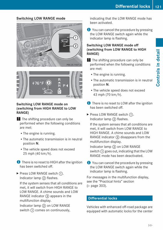
Switching LOW RANGE mode
Switching LOW RANGE mode on (switching from HIGH RANGE to LOW RANGE)! The shifting procedure can only be
performed when the following conditionsare met:RThe engine is running.RThe automatic transmission is in neutral
position N.RThe vehicle speed does not exceed
25 mph (40 km/h).
i There is no reset to HIGH after the ignitionhas been switched off.
X Press LOW RANGE switch :.Indicator lamp ; flashes.If the system senses that all conditions aremet, it will switch from HIGH RANGE toLOW RANGE. A chime sounds and LOWRANGE indicator = appears in themultifunction display.Indicator lamp ; on LOW RANGEswitch : comes on continuously,
indicating that the LOW RANGE mode hasbeen activated.
i You can cancel the procedure by pressingthe LOW RANGE switch again while theindicator lamp is flashing.
Switching LOW RANGE mode off (switching from LOW RANGE to HIGH RANGE)! The shifting procedure can only be
performed when the following conditionsare met:RThe engine is running.RThe automatic transmission is in neutral
position N.RThe vehicle speed does not exceed
43 mph (70 km/h).
i There is no reset to LOW after the ignitionhas been switched off.
X Press LOW RANGE switch :.Indicator lamp ; flashes.If the system senses that all conditions aremet, it will switch from LOW RANGE toHIGH RANGE. A chime sounds and LOWRANGE indicator = disappears from themultifunction display.Indicator lamp ; on LOW RANGEswitch : goes out, indicating that the LOWRANGE mode has been deactivated.
i You can cancel the procedure by pressingthe LOW RANGE switch again while theindicator lamp is flashing.
For messages in the multifunction display,see the “Practical hints” section(Y page 303).
Differential locks
Vehicles with enhanced off-road package areequipped with automatic locks for the center
Differential locks 121
Cont
rols
in d
etai
l
X164_AKB; 5; 31, en-USd2ureepe, Version: 2.11.8.1
2009-09-11T12:30:16+02:00 - Seite 121
Z

and rear axle differential to improve vehicletraction.The center differential compensates fordifferences in wheel rotation between thefront and rear axle.The rear axle differential compensatesdifferences between the rear wheels.
i At the front axles, the 4-ETS systemcompensates for any traction problems.
For more information on off-road driving, see“Off-road driving” (Y page 262).
A few words about differentials and differential locks
When a vehicle negotiates a turn, wheels onthe outside of the curve must travel fartherand rotate faster than the inside wheels. Thedifferential, the operation of a set of gearsthat allows the powered wheels in a vehicleto turn at different speeds, makes thisessential function possible.The drawback is that the differential alsosends most of the engine’s power to thewheel with the least load or strain on it. Forexample, if one of a vehicle’s powered wheelssits on a patch of snow and spins becausethere is no traction, all of the engine’s powerwill go to that wheel because the power willtake the path of least resistance. Meanwhile,the opposite wheel, sitting on dry pavementwhere it could get enough grip to start thevehicle moving, sits idle because it receivesno power.The 4-ETS addresses this problem andprovides for good control and steering abilityby automatically slowing the slipping wheeland thus increasing the power to the othernon-slipping drive wheels to get the vehiclemoving. The ESP® and the 4-ETS in thisvehicle feature such intelligent limited-slipdifferential technology, ideally suited for on-road and light off-road driving. Transfer caseposition LOW (Y page 120) also enhances off-road driving capabilities.
More extreme off-road conditions may call foranother solution, engaging a differential lockor preventing the differential from operatingaltogether. This vehicle comes with twodifferential locks: transfer case (center) andrear. Each can be engaged simply byoperating the rotary switch located on thecenter console (Y page 123). When thetransfer case (center) differential is locked,the combined (or average) speed of the frontwheels is identical to the combined rearwheel speed. When the rear differential islocked, both rear wheels turn at the samespeed, independent of the individual torque.Please be aware that engaging the differentiallocks will significantly reduce the steeringability of the vehicle.For your safety and the safety of others andto prevent damage to the vehicle, thedifferential locks must not be engaged whendriving on paved roads. It is important tounderstand that during on-road/paveddriving, differentials are absolutely necessaryfor providing the essential control andsteering ability of the vehicle. The differentiallocks, therefore, must not be engaged whendriving on paved roads and should only beused to the extent necessary to negotiate off-road conditions which cannot be handled bythe systems (the 4-ETS, the ESP®, and thetransfer case in LOW RANGE mode) thisvehicle comes equipped with.
Switching differential locks ! If the differential locks are engaged,
accelerate gently when setting the vehiclein motion.Only operate the vehicle on a single axledynamometer if the axle not being driven isjacked up or the associated propeller shaftis disconnected.Otherwise the transmission could bedamaged.
122 Differential locksCo
ntro
ls in
det
ail
X164_AKB; 5; 31, en-USd2ureepe, Version: 2.11.8.1
2009-09-11T12:30:16+02:00 - Seite 122

You can select between three locking modes.
Rotary switch for differential locks: Rotatable outer adjustment ring with
indicator lamp 2 AUTO mode: center differential is
automatically locked3 Center differential is completely locked4 Center and rear axle differential are
completely locked
AUTO modeThe AUTO mode is adequate for most drivingsituations since the center differential islocked and released as required.
i At speeds up to 19 mph (30 km/h), it ispossible to manually lock the differentiallocks for driving on rough terrain.
X Start the engine.The center differential lock is in AUTOmode. The indicator lamp on adjustmentring : above symbol à is on.
A message indicating that the centerdifferential lock is in AUTO mode appears inthe multifunction display when the off-roadmenu is selected. For selecting the off-roadmenu, see the “Controls in detail” section(Y page 131).
Center and rear axle differential locks
G Warning!Never drive on a paved surface with the centerand rear axle differential locks manuallyengaged. Ability to steer the vehicle is greatlyreduced when the differential locks aremanually engaged, increasing the risk of anaccident.For safety reasons, the locks areautomatically released at a vehicle speedabove 31 mph (50 km/h). Nevertheless, youshould only manually lock the differential ifabsolutely necessary because engaged lockswill restrict the vehicle drivetrain whilecornering and cause the vehicle to chatter.This could cause you to lose control of thevehicle and cause an accident.
! The differential locks must not beengaged manually when towing the vehicleor spinning the wheels.
The differential locks should only be engagedmanually if traction is insufficient in AUTOmode.The differential locks can be engaged in thesequence 3, 4 (Y page 123) up to a speedof 19 mph (30 km/h).Engage differential locks:Rfor off-road drivingRfor driving through waterRwhen driving on deep snow and icy or
fouled surfacesX Start the engine.X To select the desired locking mode, rotate
adjustment ring : to position 3 or 4(Y page 123).The indicator lamp on adjustment ring :at the respective symbol comes on.
A message indicating that the respectivedifferential is completely locked appears inthe multifunction display when the off-roadmenu is selected. For selecting the off-road
Differential locks 123
Cont
rols
in d
etai
l
X164_AKB; 5; 31, en-USd2ureepe, Version: 2.11.8.1
2009-09-11T12:30:16+02:00 - Seite 123
Z

menu, see the “Controls in detail” section(Y page 131).
Example illustrationA Center differential completely locked
! If the differential locks have beenmanually engaged, the tires will scuff on theroad surface when cornering because thedifferences between the individual wheelrotation speeds will not be compensatedfor.
i The differential locks are reset to AUTOmode after the ignition has been switchedoff for longer than 10 seconds.
Instrument cluster
IntroductionFor a full view illustration of the instrumentcluster, see “Instrument cluster”(Y page 28).
G Warning!No messages will be displayed if either theinstrument cluster or the multifunctiondisplay is inoperative.As a result, you will not be able to seeinformation about your driving conditions,such asRspeedRoutside temperatureRwarning/indicator lampsRmalfunction/warning messagesRfailure of any systems
Driving characteristics may be impaired.
If you must continue to drive, do so with addedcaution. Contact an authorized Mercedes-Benz Center as soon as possible.
: To dim instrument cluster illumination; Reset button = To brighten instrument cluster
illuminationFor information on changing the instrumentcluster settings, e.g. the language, see(Y page 133).
Activating the instrument clusterThe instrument cluster is activated when youRopen the driver’s doorRswitch on the ignitionRpress button :, ; or =
i Opening the driver’s door or pressingbutton :, ; or = without switching onthe ignition activates the instrumentcluster illumination only for 30 seconds.
Adjusting the instrument cluster illuminationX To brighten illumination: Press and hold
button = until the desired level ofillumination is reached.
X To dim illumination: Press and holdbutton : until the desired level ofillumination is reached.
124 Instrument clusterCo
ntro
ls in
det
ail
X164_AKB; 5; 31, en-USd2ureepe, Version: 2.11.8.1
2009-09-11T12:30:16+02:00 - Seite 124

i The instrument cluster illumination isdimmed or brightened automatically to suitambient light conditions.The instrument cluster illumination will alsobe adjusted automatically when you switchon the vehicle’s exterior lamps.
i With the exterior lighting switched on, thebrightness of the switches in the centerconsole will also be adjusted when usingbutton : or =.
Resetting trip odometerX Make sure you are viewing the standard
display (Y page 128) in the multifunctiondisplay.
X Press and hold the reset button in theinstrument cluster (Y page 124) until thetrip odometer is reset.
TachometerThe red marking on the tachometer(Y page 29) denotes excessive engine speed.
! Avoid driving at excessive engine speeds,as it may result in serious engine damagethat is not covered by the Mercedes-BenzLimited Warranty.
To help protect the engine, the fuel supply isinterrupted if the engine is operated withinthe red marking.
Control system
IntroductionThe control system is activated as soon as thestarter switch is in position 1 (Y page 80).The control system enables you to call upinformation about your vehicle and to changevehicle settings.For example, you can use the control systemto find out when your vehicle is next due formaintenance service, to set the language for
messages in the instrument cluster display,and much more.
G Warning!A driver’s attention to the road and trafficconditions must always be his/her primaryfocus when driving.For your safety and the safety of others,selecting features through the multifunctionsteering wheel should only be done by thedriver when traffic and road conditions permitit to be done safely.Bear in mind that at a speed of just 30 mph(approximately 50 km/h), your vehicle iscovering a distance of 44 feet (approximately14 m) every second.
The control system relays information to themultifunction display.
Multifunction steering wheelThe displays in the multifunction display andthe settings in the control system arecontrolled by using the buttons on themultifunction steering wheel.
Control system 125
Cont
rols
in d
etai
l
X164_AKB; 5; 31, en-USd2ureepe, Version: 2.11.8.1
2009-09-11T12:30:16+02:00 - Seite 125
Z

: Multifunction display
; Press button~ to end a call
to reject an incoming call6 to answer a call
to dial10
to redial10
Press buttonWX
to select submenus in theSettings menuto set valuesto set the volume
Press button? to turn Voice Control System
on11, see separate operatinginstructions
= Press buttonVU
to select next or previous menu
Press button briefly&*
to move within a menuWithin Audio/DVD menu toselect previous or next track,scene or stored stationWithin Telephone menu toswitch to the phone book andselect a name or number
Press and hold button&*
Within Audio/DVD menu toselect previous or next trackwith quick search or to selectprevious or next station instation list or wave bandWithin Telephone menu tostart the quick search in thephone book
Press buttonA to turn Voice Control System
off11, see separate operatinginstructions
Depending on the selected menu, pressingthe buttons on the multifunction steeringwheel will alter what appears in themultifunction display.The information available in the multifunctiondisplay is arranged in menus andaccompanying functions and submenus.The individual functions are then found withinthe relevant menu (radio or CD operationsunder Audio/DVD menu, for example).These functions serve to call up relevantinformation or to customize the settings foryour vehicle.It is helpful to think of the menus, and thefunctions within each menu, as beingarranged in a circular pattern.X Press button V or U repeatedly to
pass through each menu one after theother.
X Press button * or & repeatedly topass through each function display, oneafter the other, in the current menu.
In the Settings menu, instead of functions,you will find a number of submenus for callingup and changing settings. For instructions onusing these submenus, see “Settings menu”(Y page 132).
10 Function only available in telephone menu.11 Vehicles without Voice Control System: Button without function.
126 Control systemCo
ntro
ls in
det
ail
X164_AKB; 5; 31, en-USd2ureepe, Version: 2.11.8.1
2009-09-11T12:30:16+02:00 - Seite 126
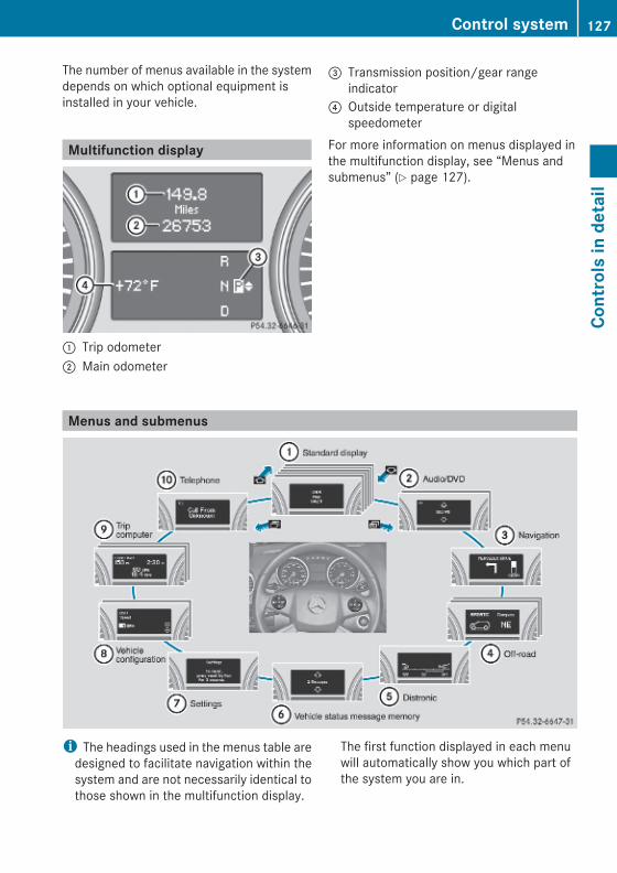
The number of menus available in the systemdepends on which optional equipment isinstalled in your vehicle.
Multifunction display
: Trip odometer; Main odometer
= Transmission position/gear rangeindicator
? Outside temperature or digitalspeedometer
For more information on menus displayed inthe multifunction display, see “Menus andsubmenus” (Y page 127).
Menus and submenus
i The headings used in the menus table aredesigned to facilitate navigation within thesystem and are not necessarily identical tothose shown in the multifunction display.
The first function displayed in each menuwill automatically show you which part ofthe system you are in.
Control system 127
Cont
rols
in d
etai
l
X164_AKB; 5; 31, en-USd2ureepe, Version: 2.11.8.1
2009-09-11T12:30:16+02:00 - Seite 127
Z

Function
: Standard display menu(Y page 128)
; Audio/DVD menu (Y page 129)
= Navigation menu (Y page 130)
? Off-road menu (Y page 131)
A Distronic menu (Y page 131)
B Vehicle status message memory12 menu (Y page 131)
C Settings menu (Y page 132)
D Vehicle configuration menu(Y page 140)
E Trip computer menu (Y page 141)
F Telephone menu (Y page 142)
Standard display menu
Standard display
In the standard display, trip odometer : andmain odometer ; appear in themultifunction display.X If you see another display, press buttonV or U repeatedly until the standarddisplay appears.
X Press button & or * to select thefunctions in the Standard display menu.
The following functions are available:RRestarting the tire pressure loss warning
system (Y page 238) (Canada only)RChecking tire inflation pressure with the
Advanced TPMS (Y page 239) (USA only)RChecking coolant temperature
(Y page 128)RCalling up digital speedometer or outside
temperature (Y page 129)RCalling up maintenance service indicator
display (Y page 274)
Checking coolant temperature
G Warning!Driving when your engine is overheated cancause some fluids which may have leaked intothe engine compartment to catch fire. Youcould be seriously burned.Steam from an overheated engine can causeserious burns which can occur just by openingthe engine hood. Stay away from the engineif you see or hear steam coming from it.Stop the vehicle in a safe location away fromother traffic. Turn off the engine, get out of thevehicle and do not stand near the vehicle untilthe engine has cooled down.
X Press button & or * repeatedly untilthe coolant temperature appears in themultifunction display.
During severe operating conditions, e.g. stop-and-go traffic, the coolant temperature mayrise close to 248‡ (120†).
! Excessive coolant temperature triggers awarning in the multifunction display.
12 The vehicle status message memory menu is only displayed if there is a message stored.
128 Control systemCo
ntro
ls in
det
ail
X164_AKB; 5; 31, en-USd2ureepe, Version: 2.11.8.1
2009-09-11T12:30:16+02:00 - Seite 128

The engine should not be operated with acoolant temperature above 248‡(120†). Doing so may cause seriousengine damage which is not covered by theMercedes-Benz Limited Warranty.
Calling up digital speedometer or outside temperature You can select whether the digitalspeedometer or the outside temperatureappears in the multifunction display(Y page 135).
G Warning!The outside temperature indicator is notdesigned to serve as an ice-warning deviceand is therefore unsuitable for that purpose.Indicated temperatures just above thefreezing point do not guarantee that the roadsurface is free of ice. The road may still be icy,especially in wooded areas or on bridges.
X Press button & or * repeatedly untilthe digital speedometer or the outsidetemperature appears in the multifunctiondisplay.
Digital speedometer
Outside temperature
Audio/DVD menuThe functions in the Audio/DVD menuoperate the audio or video equipment whichyou have currently switched on.The following functions are available:RSelecting radio station (Y page 129)ROperating audio devices/audio media
(Y page 130)ROperating video DVD (Y page 130)If no audio equipment is currently switchedon, the message AUDIO Off appears in themultifunction display.
Selecting radio station The HD Radio with SIRIUS Satellite Radio istreated as a radio application.For more information on HD Radio withSIRIUS Satellite Radio, refer to separateCOMAND system operating instructions.Additional optional satellite radio equipmentand a subscription to a satellite radio serviceprovider are required for satellite radiooperation. Contact an authorized Mercedes-Benz Center for details and availability foryour vehicle.X Switch on the COMAND system and select
radio. Refer to separate COMAND systemoperating instructions.
X Press button V or U repeatedly untilthe currently tuned station appears in themultifunction display.
Example illustration: Wave band setting and stored memory
position; Station frequency
Control system 129
Cont
rols
in d
etai
l
X164_AKB; 5; 31, en-USd2ureepe, Version: 2.11.8.1
2009-09-11T12:30:16+02:00 - Seite 129
Z

X Selecting next or previous stored station: Press button * or & brieflyto select a stored station.
X Selecting next or previous station in the station list: Press and hold button * or& to select a station.
X Selecting next or previous station in wave band (Only if no station list isavailable): Press and hold button * or& to select a station.
You can only store new stations using thecorresponding feature on the radio. Refer toseparate COMAND system operatinginstructions.You can also operate the radio in the usualmanner.
Operating audio devices/audio mediaX Switch on the COMAND system and select
the audio device or audio media. Refer toseparate COMAND system operatinginstructions.
X Press button V or U repeatedly untilthe Audio/DVD menu appears in themultifunction display.
Example illustration: Disc number; Current track
X Selecting next or previous track: Pressbutton * or & briefly.
X Selecting a track from the track list (quick search): Press and hold button* or &.
The current track does not appear duringAudio AUX mode operation.
Operating video DVDX Switch on the COMAND system and select
DVD-Video. Refer to separate COMANDsystem operating instructions.
X Press button V or U repeatedly untilthe Audio/DVD menu appears in themultifunction display.
: Disc number; Current scene
X Press button * or & to select ascene.
Navigation menuThe Navigation menu contains the functionsneeded to operate your navigation system.X Press button V or U repeatedly until
the Navigation menu appears in themultifunction display.The message shown in the multifunctiondisplay depends on the status of thenavigation system:RWith the COMAND system switched off,
the message NAVI Off appears in themultifunction display.RWith the COMAND system switched on
but route guidance not activated, thedirection of travel and, if applicable, thename of the street currently traveled onappear in the multifunction display.RWith the COMAND system switched on
and route guidance activated, thedirection of travel and maneuverinstructions appear in the multifunctiondisplay.
130 Control systemCo
ntro
ls in
det
ail
X164_AKB; 5; 31, en-USd2ureepe, Version: 2.11.8.1
2009-09-11T12:30:16+02:00 - Seite 130

Please refer to separate COMAND systemoperating instructions for instructions on howto activate the route guidance system.
Off-road menuThe Off-road menu displays the messages forair suspension, differential locks and thedirection into which you are currently driving.X Press button V or U repeatedly until
one of the following messages appears inthe multifunction display.
Vehicles with air suspension:
Vehicles with air suspension and differentiallocks:
For information on air suspension, see “Airsuspension program” (Y page 159).For information on differential locks, see“Differential locks” (Y page 121).For information on the compass, see“Compass” (Y page 223).
Distronic menuUse the Distronic menu to display thecurrent settings for your Distronic system.The information shown in the multifunctiondisplay depends on whether the Distronicsystem is activated or deactivated.
Please refer to the “Driving systems” sectionof this manual (Y page 147) for instructionson how to activate Distronic.
Vehicle status message memory menu
Use the Vehicle status message memorymenu to scan malfunction and warningmessages that may be stored in the memory.Such messages appear in the multifunctiondisplay and are based on conditions orsystem status the vehicle’s system hasrecorded.The Vehicle status message memory menuonly appears if messages have been stored.
G Warning!Malfunction and warning messages are onlyindicated for certain systems and areintentionally not very detailed. Themalfunction and warning messages aresimply a reminder with respect to theoperation of certain systems. They do notreplace the owner’s and/or driver’sresponsibility to maintain the vehicle’soperating safety. Have all requiredmaintenance and safety checks performed onthe vehicle. Bring the vehicle to an authorizedMercedes-Benz Center to address themalfunction and warning messages.
X Press button V or U repeatedly untilthe Vehicle status message memorymenu appears in the multifunction display.If conditions have occurred causing statusmessages to be recorded, the number ofmessages appears in the multifunctiondisplay.
Control system 131
Cont
rols
in d
etai
l
X164_AKB; 5; 31, en-USd2ureepe, Version: 2.11.8.1
2009-09-11T12:30:16+02:00 - Seite 131
Z

X Press button & or *.The stored messages will now be displayedin the order in which they have occurred.For malfunction and warning messages,see “Vehicle status messages in themultifunction display” (Y page 287).
i After you have scrolled through allrecorded status messages, the firstrecorded message appears again.
Should the vehicle’s system record anyconditions while driving, the number ofmessages will reappear in the multifunctiondisplay when the SmartKey in the starterswitch is turned to position 0 or removedfrom the starter switch. With KEYLESS-GO,the number of messages will reappear whenyou turn off the engine by pressing theKEYLESS-GO start/stop button and open thedriver’s door.Except for high-priority messages, the vehiclestatus message memory will be cleared whenyou switch off the ignition.
Settings menu
IntroductionIn the Settings menu there are twofunctions: The function To reset, press reset button for 3 seconds, with whichyou can reset all the settings to the originalfactory settings and a collection of submenuswith which you can make individual settingsfor your vehicle.The following settings and submenus areavailable in the Settings menu:RResetting to factory settings
(Y page 132)RSubmenus in the Settings menu
(Y page 133)RInstrument cluster submenu
(Y page 133)RTime/Date submenu (Y page 135)RLighting submenu (Y page 136)
RVehicle submenu (Y page 138)RComfort submenu (Y page 139)
Resetting to factory settingsYou can reset the settings of all submenus tothe factory settings.For safety reasons, the function Lamp Circuit Headlamp in the Lightingsubmenu cannot be reset while driving.The following message appears in themultifunction display:SettingsCannot becompletely resetto factory settingswhen engine is running.X Press button V or U repeatedly until
the Settings menu appears in themultifunction display.
X Press the reset button in the instrumentcluster (Y page 124) for approximately3 seconds.The request to press the reset button oncemore to confirm appears in themultifunction display.
X Press the reset button once more.The settings you have changed will not bereset unless you confirm the action bypressing the reset button a second time. After
132 Control systemCo
ntro
ls in
det
ail
X164_AKB; 5; 31, en-USd2ureepe, Version: 2.11.8.1
2009-09-11T12:30:16+02:00 - Seite 132

approximately 5 seconds, the Settingsmenu reappears in the multifunction display.
Submenus in the Settings menuX Press button V or U repeatedly until
the Settings menu appears in themultifunction display.
X Press button &.The collection of the submenus appears inthe multifunction display. There are moresubmenus than can be displayedsimultaneously.
X Press button X.The selection marker moves to the nextsubmenu.
X Scroll down with button X, scroll upwith button W.
X With the selection marker on the desiredsubmenu, use button & to access theindividual functions within that submenu.
X Once within the submenu, use button& to move to the next function or button* to move to the previous functionwithin that submenu.
X Use button W or X to change thesettings of the respective function.
The following lists show what settings can bechanged within the various menus. Detailedinstructions on making individual settings canbe found on the following pages.
Instrument cluster submenuRSelecting speedometer/odometer display
mode (Y page 134) (Canada only)RSelecting digital speedometer display
mode (Y page 134)
RSelecting language (Y page 134)RSelecting display (digital speedometer or
outside temperature) for status indicator(Y page 135)
Time/Date submenuRSetting the time (Y page 135)RSetting the date (Y page 135)
Lighting submenuRSwitching daytime running lamp mode on
or off (USA only) (Y page 136)RSwitching locator lighting on or off
(Y page 136)RSetting ambient lighting (Y page 137)RSwitching night security illumination
(Headlamps delayed shut-off feature) on oroff (Y page 137)RSwitching interior lighting delayed shut-off
on or off (Y page 138)
Vehicle submenuRSwitching automatic central locking on or
off (Y page 138)
Comfort submenuRActivating easy-entry/exit feature
(Y page 139)RActivating/deactivating seat belt
adjustment feature (Y page 139)RSwitching fold-in function for exterior rear
view mirrors on or off (Y page 140)
Instrument cluster submenuAccess the Instrument Cluster submenuvia the Settings menu. Use theInstrument Cluster submenu to changethe instrument cluster display settings.
Control system 133
Cont
rols
in d
etai
l
X164_AKB; 5; 31, en-USd2ureepe, Version: 2.11.8.1
2009-09-11T12:30:16+02:00 - Seite 133
Z

The following functions are available:RSelecting speedometer/odometer display
mode (Y page 134) (Canada only)RSelecting digital speedometer display
mode (Y page 134)RSelecting language (Y page 134)RSelecting display (digital speedometer or
outside temperature) for status indicator(Y page 135)
Selecting speedometer/odometer display mode (Canada only) X Press button V or U repeatedly until
the Settings menu appears in themultifunction display.
X Press button &.X Move the selection marker with buttonW or X to the Instrument Cluster submenu.
X Press button & or * repeatedly untilthe message Display Unit Speedometer/Odometer appears in themultifunction display.The selection marker is on the currentsetting.
X Press button W or X to setspeedometer/odometer unit to Km orMiles.
Selecting digital speedometer display mode X Press button V or U repeatedly until
the Settings menu appears in themultifunction display.
X Press button &.
X Move the selection marker with buttonW or X to the Instrument Cluster submenu.
X Press button & or * repeatedly untilthe message Display Unit Digital Speedometer appears in the multifunctiondisplay.The selection marker is on the currentsetting.
X Press button W or X to set digitalspeedometer unit to Km or Miles.
Selecting language X Press button V or U repeatedly until
the Settings menu appears in themultifunction display.
X Press button &.X Move the selection marker with buttonW or X to the Instrument Cluster submenu.
X Press button & or * repeatedly untilthe message Language appears in themultifunction display.The selection marker is on the currentsetting.
X Press button W or X to select thelanguage to be used for the multifunctiondisplay messages.
134 Control systemCo
ntro
ls in
det
ail
X164_AKB; 5; 31, en-USd2ureepe, Version: 2.11.8.1
2009-09-11T12:30:16+02:00 - Seite 134

Selecting display (digital speedometer or outside temperature) for status indicator X Press button V or U repeatedly until
the Settings menu appears in themultifunction display.
X Press button &.X Move the selection marker with buttonW or X to the Instrument Cluster submenu.
X Press button & or * repeatedly untilthe message Status Line Displayappears in the multifunction display.The selection marker is on the currentsetting.
X Press button W or X to select thedesired setting.The selected display is then showncontinuously in the status indicator (lowerdisplay).The other display now appears in theStandard display menu (Y page 128).
Time/Date submenuAccess the Time/Date submenu via theSettings menu. Use the Time/Datesubmenu to change the time and date displaysettings.The following functions are available:RSetting the time (Y page 135)RSetting the date (Y page 135)If your vehicle is equipped with the COMANDsystem and navigation module, see separateCOMAND system operating instructions forinformation on how to set the time and date.
Setting the time This function is not available if your vehicle isequipped with the COMAND system andnavigation module.X Press button V or U repeatedly until
the Settings menu appears in themultifunction display.
X Press button &.X Move the selection marker with buttonW or X to the Time/Date submenu.
X Press button & or * repeatedly untilthe message Clock Set Hour or Clock Set Minute(s) appears in themultifunction display.The selection marker is on the currentsetting.
Example illustration for setting the hour
X Press button W or X to set the hoursor minute(s).
Setting the date This function is not available if your vehicle isequipped with the COMAND system andnavigation module.X Press button V or U repeatedly until
the Settings menu appears in themultifunction display.
X Press button &.X Move the selection marker with buttonW or X to the Time/Date submenu.
X Press button & or * repeatedly untilthe message Date Set Month, Date Set Day, or Date Set Year appears in themultifunction display.The selection marker is on the currentsetting.
Control system 135
Cont
rols
in d
etai
l
X164_AKB; 5; 31, en-USd2ureepe, Version: 2.11.8.1
2009-09-11T12:30:16+02:00 - Seite 135
Z

Example illustration for setting the month
X Press button W or X to set themonth, day, or year.
Lighting submenuAccess the Lighting submenu via theSettings menu. Use the Lighting submenuto change the lamp and lighting settings onyour vehicle.The following functions are available:RSwitching daytime running lamp mode on
or off (USA only) (Y page 136)RSwitching locator lighting on or off
(Y page 136)RSetting ambient lighting (Y page 137)RSwitching night security illumination on or
off (Y page 137)RSwitching interior lighting delayed shut-off
on or off (Y page 138)
Switching daytime running lamp mode on or off (USA only) X Press button V or U repeatedly until
the Settings menu appears in themultifunction display.
X Press button &.X Move the selection marker with buttonW or X to the Lighting submenu.
X Press button & or * repeatedly untilthe message Daytime Running Lampsappears in the multifunction display.The selection marker is on the currentsetting.
X Press button W or X to switch thedaytime running lamp mode On or Off.
With daytime running lamp mode activatedand the exterior lamp switch inposition $ or Ã, the daytime runninglamps are switched on when the engine isrunning.In low ambient light conditions the followinglamps will come on additionally:RLow-beam headlampsRParking lampsRTail lampsRLicense plate lampsRSide marker lampsFor more information on the daytime runninglamp mode, see (Y page 99).For safety reasons, changing the setting forthe daytime running lamp mode is notpossible while the vehicle is in motion.The following message appears in themultifunction display:Settings can only be made with engine off.For safety reasons, resetting all the functionsof all submenus to the factory settings whiledriving (Y page 132) will not deactivate thedaytime running lamp mode.
Switching locator lighting on or off With the locator lighting feature activated, theexterior lamp switch in position à and theinterior lighting in automatic mode, thefollowing lamps will come on during darknesswhen the vehicle is unlocked using button% on the SmartKey:
136 Control systemCo
ntro
ls in
det
ail
X164_AKB; 5; 31, en-USd2ureepe, Version: 2.11.8.1
2009-09-11T12:30:16+02:00 - Seite 136

RParking lampsRTail lampsRLicense plate lampsRSide marker lampsRFront fog lampsThe locator lighting goes out when the driver’sdoor is opened.If you do not open the driver’s door afterunlocking the vehicle with the SmartKey, thelamps will go out automatically afterapproximately 40 seconds.X Press button V or U repeatedly until
the Settings menu appears in themultifunction display.
X Press button &.X Move the selection marker with buttonW or X to the Lighting submenu.
X Press button & or * repeatedly untilthe message Surround Lighting Function appears in the multifunctiondisplay.The selection marker is on the currentsetting.
X Press button W or X to switch thelocator lighting function On or Off.
X Turn the exterior lamp switch to positionà when exiting the vehicle.The locator lighting feature is activated.
Setting ambient lightingUse this function to adjust the brightness ofthe ambient lighting.X Press button V or U repeatedly until
the Settings menu appears in themultifunction display.
X Press button &.
X Move the selection marker with buttonW or X to the Lighting submenu.
X Press button & or * repeatedly untilthe message Ambient Light Levelappears in the multifunction display.The selection marker is on the currentsetting.
X Press button W or X to select thedesired brightness of the ambient lighting.The setting 1 represents the darkest leveland setting 5 the brightest level. Theambient light is switched off at setting 0.
Switching night security illumination (Headlamps delayed shut-off feature) on or off Use this function to set whether you wouldlike the exterior lamps to remain on for15 seconds during darkness after exiting thevehicle and closing all doors.With the headlamps delayed shut-off featureactivated and the exterior lamp switch inposition à before the engine is turned off,the following lamps will come on when theengine is turned off:RParking lampsRTail lampsRLicense plate lampsRSide marker lampsRFront fog lampsIf, after turning off the engine, you do notopen a door or do not close an opened door,the lamps will automatically go out after60 seconds.
Control system 137
Cont
rols
in d
etai
l
X164_AKB; 5; 31, en-USd2ureepe, Version: 2.11.8.1
2009-09-11T12:30:16+02:00 - Seite 137
Z

X Press button V or U repeatedly untilthe Settings menu appears in themultifunction display.
X Press button &.X Move the selection marker with buttonW or X to the Lighting submenu.
X Press button & or * repeatedly untilthe message Headlamp Delayed Shut-off appears in the multifunction display.The selection marker is on the currentsetting.
X Press button W or X to switch theheadlamps delayed shut-off feature On orOff.
X Turn the exterior lamp switch to positionà before turning off the engine.The headlamps delayed shut-off feature isactivated.
You can temporarily deactivate theheadlamps delayed shut-off feature:X Before exiting the vehicle, turn the
SmartKey in the starter switch to position0.
X Then turn it to position 2 and back toposition 0.The headlamps delayed shut-off feature isdeactivated. It will reactivate as soon asyou start the engine.
Switching interior lighting delayed shut-off on or off Use this function to set whether you wouldlike the interior lighting to remain on for10 seconds during darkness after you haveremoved the SmartKey from the starterswitch.
X Press button V or U repeatedly untilthe Settings menu appears in themultifunction display.
X Press button &.X Move the selection marker with buttonW or X to the Lighting submenu.
X Press button & or * repeatedly untilthe message Interior Lighting Delayed Shut-off appears in themultifunction display.The selection marker is on the currentsetting.
X Press button W or X to switch theinterior lighting delayed shut-off featureOn or Off.
Vehicle submenuAccess the Vehicle submenu via theSettings menu. Use the Vehicle submenuto set the automatic central locking.
Switching automatic central locking on or off Use this function to switch the automaticcentral locking on or off. With the automaticcentral locking activated, the vehicle islocked centrally at a vehicle speed ofapproximately 9 mph (15 km/h).X Press button V or U repeatedly until
the Settings menu appears in themultifunction display.
X Press button &.
138 Control systemCo
ntro
ls in
det
ail
X164_AKB; 5; 31, en-USd2ureepe, Version: 2.11.8.1
2009-09-11T12:30:16+02:00 - Seite 138

X Move the selection marker with buttonW or X to the Vehicle submenu.
X Press button & or * repeatedly untilthe message Automatic Door Lockingappears in the multifunction display.The selection marker is on the currentsetting.
X Press button W or X to switch theautomatic central locking On or Off.
Comfort submenuAccess the Comfort submenu via theSettings menu.The following functions are available:RActivating easy-entry/exit feature
(Y page 139)RActivating/deactivating the seat belt
adjustment feature (Y page 139)RSwitching fold-in function for exterior rear
view mirrors on or off (Y page 140)
Activating easy-entry/exit feature Use this function to activate and deactivatethe easy-entry/exit feature (Y page 92).
G Warning!You must make sure no one can becometrapped or injured by the moving steeringwheel when the easy-entry/exit feature isactivated.To stop steering wheel movement do one ofthe following:RMove steering wheel adjustment stalk.RPress one of the memory position buttons.RPress memory button M.
Do not leave children unattended in thevehicle, or with access to an unlocked vehicle.Children could open the driver’s door andunintentionally activate the easy-entry/exitfeature, which could result in an accidentand/or serious personal injury.
X Press button V or U repeatedly untilthe Settings menu appears in themultifunction display.
X Press button &.X Move the selection marker with buttonW or X to the Comfort submenu.
X Press button & or * repeatedly untilthe message Easy-entry Functionappears in the multifunction display.The selection marker is on the currentsetting.
X Press button W or X to activate (On)or deactivate (Off) the easy-entry/exitfeature.
Activating/deactivating seat belt adjustment featureUse this feature to set the seat belts to beadjusted automatically with the driver’s orfront passenger seat belt fastened and thestarter switch in position 2.For more information on the seat beltadjustment feature, see (Y page 51).X Press button V or U repeatedly until
the Settings menu appears in themultifunction display.
X Press button &.
Control system 139
Cont
rols
in d
etai
l
X164_AKB; 5; 31, en-USd2ureepe, Version: 2.11.8.1
2009-09-11T12:30:16+02:00 - Seite 139
Z

X Move the selection marker with buttonW or X to the Comfort submenu.
X Press button & or * repeatedly untilthe message Belt Adjustment appears inthe multifunction display.The selection marker is on the currentsetting.
X Press button W or X to active (On) ordeactivate (Off) the seat belt adjustmentfeature.
Switching fold-in function for exterior rear view mirrors on or off Use this function to set the exterior rear viewmirrors to be folded in automatically whenyou lock your vehicle.With this function set to On and the exteriorrear view mirrors folded in using the buttonon the door control panel (Y page 95), theexterior rear view mirrors will not fold outwhen you switch on the ignition. You will thenhave to fold out the exterior rear view mirrorsusing the button on the door control panel(Y page 95).Make sure both exterior rear view mirrors arefolded out completely before driving off.X Press button V or U repeatedly until
the Settings menu appears in themultifunction display.
X Press button &.X Move the selection marker with buttonW or X to the Comfort submenu.
X Press button & or * repeatedly untilthe message Fold In Mirrors When Locking appears in the multifunctiondisplay.The selection marker is on the currentsetting.
X Press button W or X to switch thefunction On or Off.
Vehicle configuration menuUse the Vehicle configuration menu toactivate/deactivate the Distance warningfunction (Y page 140) or to set the DSRspeed (Y page 141).
Distance warning functionIn vehicles equipped with Distronic, you candetermine whether the distance warningfunction is to be enabled or disabled. With thisfunction set to On, the system will alert youwhen recognizing a stationary obstacle or aslower vehicle moving in your vehicle’s pathand the danger of a collision exists, evenwhen the Distronic is switched off.X Press button V or U repeatedly until
the vehicle configuration menu appearsin the multifunction display.
X Press button & or * repeatedly untilthe message Distance Warning appearsin the multifunction display.The selection marker is on the currentsetting.
X Press button W or X to switch thedistance warning function On or Off.
140 Control systemCo
ntro
ls in
det
ail
X164_AKB; 5; 31, en-USd2ureepe, Version: 2.11.8.1
2009-09-11T12:30:16+02:00 - Seite 140

: Symbol for activated distance warningfunction
If the distance warning function is switchedon you will see the symbol Ä in theStandard display. When the distance warningfunction is switched off the symbol Ä willnot appear.
DSR (Downhill Speed Regulation) programmed default speedUse this function to program the defaultspeed the DSR is set to when it is activated.You can program the default speed between3 - 10 mph (Canada: 4- 18 km/h). The setvalue is increased in 1 mph (Canada:2 km/h) increments.X Press button V or U repeatedly until
the Vehicle configuration menu appearsin the multifunction display.
X Press button & or * repeatedly untilthe message DSR Speed appears in themultifunction display.The selection marker is on the currentsetting.
X Press button W or X repeatedly untilthe desired speed is shown in themultifunction display.When DSR is switched on, DSR will use theprogrammed default speed to regulate thevehicle’s speed.
Once DSR is switched on, you can adjust theset speed using the cruise control lever(Y page 157).
Trip computer menuUse the Trip computer menu to call upstatistical data on your vehicle.The following information is available:RFuel consumption statistics since start
(Y page 141)RFuel consumption statistics since last reset
(Y page 142)RResetting fuel consumption statistics
(Y page 142)RDistance to empty (Y page 142)RCurrent fuel consumption (Y page 142)When you enter the Trip computer menu,you will always see the fuel consumptionstatistics since start first.
Fuel consumption statistics since start X Press button U or V repeatedly until
the message From Start appears in themultifunction display.
: Distance driven since start; Time elapsed since start= Average speed since start? Average fuel consumption since start
All statistics stored since the last engine startwill be reset approximately 4 hours after theSmartKey in the starter switch is turned toposition 0 or removed from the starter switch.Resetting will not occur if you turn theSmartKey back to position 1 or 2 within thistime period.
Control system 141
Cont
rols
in d
etai
l
X164_AKB; 5; 31, en-USd2ureepe, Version: 2.11.8.1
2009-09-11T12:30:16+02:00 - Seite 141
Z

Fuel consumption statistics since last resetX Press button U or V repeatedly until
the message From Start appears in themultifunction display.
X Press button & or * repeatedly untilthe message From Reset appears in themultifunction display.
: Distance driven since last reset; Time elapsed since last reset= Average speed since last reset? Average fuel consumption since last reset
Resetting fuel consumption statisticsX Press button U or V repeatedly until
the message From Start appears in themultifunction display.
X Press button & or * repeatedly untilthe reading that you want to reset appearsin the multifunction display.
X Press and hold the reset button in theinstrument cluster until the respectivevalues are reset to 0.
The fuel consumption statistics resetautomatically to 0 after 99 999 miles or9 999 hours, whichever occurs first.
Distance to emptyX Press button U or V repeatedly until
the message From Start appears in themultifunction display.
X Press button & or * repeatedly untilthe message Range: appears in themultifunction display.The calculated remaining driving rangebased on the current fuel tank levelappears in the multifunction display.If only very little fuel is left in the tank, avehicle at the fuel pump C appearsinstead of the remaining driving range.
Current fuel consumptionX Press button U or V repeatedly until
the message From Start appears in themultifunction display.
X Press button & or * repeatedly untilthe message Consumption appears in themultifunction display.The current fuel consumption appears inthe multifunction display.
Telephone menu
G Warning!A driver’s attention to the road must alwaysbe his/her primary focus when driving. For
142 Control systemCo
ntro
ls in
det
ail
X164_AKB; 5; 31, en-USd2ureepe, Version: 2.11.8.1
2009-09-11T12:30:16+02:00 - Seite 142

your safety and the safety of others, werecommend that you pull over to a safelocation and stop before placing or taking atelephone call. If you choose to use thetelephone while driving, please use the hands-free device and only use the telephone whenweather, road and traffic conditions permit.Some jurisdictions prohibit the driver fromusing a mobile phone while driving a vehicle.Bear in mind that at a speed of just 30 mph(approximately 50 km/h), your vehicle iscovering a distance of 44 feet (approximately14 m) every second.
You can connect your telephone to theCOMAND system via Bluetooth®, seeseparate COMAND system operatinginstructions.X Switch on the COMAND system.
Refer to separate COMAND systemoperating instructions.
X Press button U or V repeatedly untilthe message TEL appears in themultifunction display.One of the following messages will appearin the multifunction display:RNo Service: No network is available.RBluetooth Ready: The telephone has
not been connected to the COMANDsystem via Bluetooth® yet.X Connect the telephone to the
COMAND system via Bluetooth®.
RReady or name of the network provider(if available): The telephone has found anetwork and is ready for use. You canoperate it using the control system.
Answering a call When your telephone is ready to receive calls,you can answer a call at any time. In themultifunction display you will then see thefollowing message, or if available, the callerID (number or name):
X Press button 6.You have answered the call.
Ending a call or rejecting an incoming callX Press button ~.
Dialing a number from the phone book When your telephone is ready to receive calls,you may select and dial a number from thephone book at any time.X Press button U or V repeatedly until
the message TEL appears in themultifunction display.
X Press button & or * repeatedly untilthe desired name appears in themultifunction display.If you press and hold button & or* for longer than 1 second, the systemscrolls rapidly through the list of namesuntil you release the button again.The stored names are displayed inalphabetical order.
: Selected name from the phone book
X Press button 6.The control system dials the selectedphone number.
Control system 143
Cont
rols
in d
etai
l
X164_AKB; 5; 31, en-USd2ureepe, Version: 2.11.8.1
2009-09-11T12:30:16+02:00 - Seite 143
Z

If the connection is successful and thisfeature is supported by your networkprovider, the name of the party (if stored inyour phone book) you are calling willappear in the multifunction display.The control system stores the dialednumber in the redial memory.
orX Press button ~ if you do not want to
make the call.
Redialing The control system stores the most recentlydialed phone numbers. This eliminates theneed to search through your entire phonebook.X Press button U or V repeatedly until
the message TEL appears in themultifunction display.
X Press button 6.The first number in the redial memoryappears in the multifunction display.
X Press button & or * repeatedly untilthe desired number or name appears in themultifunction display.
X Press button 6.The control system dials the selectedphone number.
Driving systems
IntroductionThis section describes the following drivingsystems of your vehicle:RCruise controlRDistronic
RDistance warning function (only availablewith Distronic)RHill-start assist systemRDownhill Speed Regulation (DSR)ROff-road driving program (vehicles without
enhanced off-road package)RAir suspension program (Adaptive
Damping System (ADS) and vehicle levelcontrol)RAll-wheel drive (4MATIC)RParktronic systemRRear view cameraVehicles with enhanced off-road package:For information on LOW RANGE mode, see“LOW RANGE mode” (Y page 120) and forinformation on differential locks, see“Differential locks” (Y page 121).The driving safety systems ABS, BAS, EBP,ESP® and 4-ETS are described in the “Safetyand security” section (Y page 61).
Cruise controlThe cruise control maintains the speed youset for your vehicle automatically.The use of the cruise control is recommendedfor driving at a constant speed for extendedperiods of time.The currently set speed or last set speed(“Resume” function) appears in the statusindicator of the multifunction display:RUSA only: e.g. Cruise 55 MilesRCanada only: e.g. ¯ 90 Km/hi The cruise control should not be activated
during off-road driving.
G Warning!The cruise control is a convenience systemdesigned to assist the driver during vehicleoperation. The driver is and must always
144 Driving systemsCo
ntro
ls in
det
ail
X164_AKB; 5; 31, en-USd2ureepe, Version: 2.11.8.1
2009-09-11T12:30:16+02:00 - Seite 144

remain responsible for the vehicle’s speedand for safe brake operation.Only use the cruise control if the road, traffic,and weather conditions make it advisable totravel at a constant speed.RThe use of the cruise control can be
dangerous on winding roads or in heavytraffic because conditions do not allow safedriving at a constant speed.RThe use of the cruise control can be
dangerous on slippery roads. Rapidchanges in tire traction can result in wheelspin and loss of control.RDeactivate the cruise control when driving
in fog.
The “Resume” function should only beoperated if the driver is fully aware of thepreviously set speed and wishes to resumethis particular preset speed.
G Warning!When the cruise control is braking, the brakepedal is retracted (i.e. depressedautomatically). The pedals’ range of motionmust not be impeded by any obstacles:RDo not place any objects in the footwell.RMake sure that the floormats and carpets
are securely in place.RDo not rest your foot underneath the brake
pedal, as it could otherwise be trapped.
You could otherwise cause an accident andinjure yourself and/or others.
: Setting current or higher speed ; Setting current or lower speed= Canceling the cruise control? Activating the cruise control or resuming
to last set speed
Activating cruise control You can activate the cruise control at avehicle speed above 20 mph (30 km/h).You cannot activate the cruise controlRwhen you brakeRwhen you have engaged the parking brakeRwhen the automatic transmission is in park
position P, reverse gear R, or neutralposition NRthe ESP® is switched off or has switched off
due to a malfunctionThe vehicle speed displayed in thespeedometer can briefly vary from the speedsetting for the cruise control system.
Setting current speed X Accelerate or decelerate to the desired
speed.X Briefly lift the cruise control lever in
direction of arrow : or press in directionof arrow ;.
X Remove your foot from the acceleratorpedal.
i On uphill grades, the cruise control maynot be able to maintain the set speed. Once
Driving systems 145
Cont
rols
in d
etai
l
X164_AKB; 5; 31, en-USd2ureepe, Version: 2.11.8.1
2009-09-11T12:30:16+02:00 - Seite 145
Z
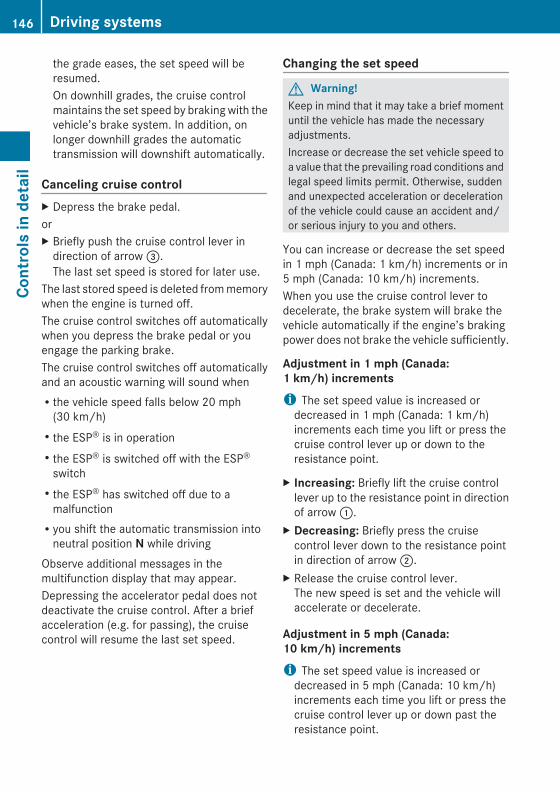
the grade eases, the set speed will beresumed.On downhill grades, the cruise controlmaintains the set speed by braking with thevehicle’s brake system. In addition, onlonger downhill grades the automatictransmission will downshift automatically.
Canceling cruise control X Depress the brake pedal.orX Briefly push the cruise control lever in
direction of arrow =.The last set speed is stored for later use.
The last stored speed is deleted from memorywhen the engine is turned off.The cruise control switches off automaticallywhen you depress the brake pedal or youengage the parking brake.The cruise control switches off automaticallyand an acoustic warning will sound whenRthe vehicle speed falls below 20 mph
(30 km/h)Rthe ESP® is in operationRthe ESP® is switched off with the ESP®
switchRthe ESP® has switched off due to a
malfunctionRyou shift the automatic transmission into
neutral position N while drivingObserve additional messages in themultifunction display that may appear.Depressing the accelerator pedal does notdeactivate the cruise control. After a briefacceleration (e.g. for passing), the cruisecontrol will resume the last set speed.
Changing the set speed
G Warning!Keep in mind that it may take a brief momentuntil the vehicle has made the necessaryadjustments.Increase or decrease the set vehicle speed toa value that the prevailing road conditions andlegal speed limits permit. Otherwise, suddenand unexpected acceleration or decelerationof the vehicle could cause an accident and/or serious injury to you and others.
You can increase or decrease the set speedin 1 mph (Canada: 1 km/h) increments or in5 mph (Canada: 10 km/h) increments.When you use the cruise control lever todecelerate, the brake system will brake thevehicle automatically if the engine’s brakingpower does not brake the vehicle sufficiently.
Adjustment in 1 mph (Canada: 1 km/h) incrementsi The set speed value is increased or
decreased in 1 mph (Canada: 1 km/h)increments each time you lift or press thecruise control lever up or down to theresistance point.
X Increasing: Briefly lift the cruise controllever up to the resistance point in directionof arrow :.
X Decreasing: Briefly press the cruisecontrol lever down to the resistance pointin direction of arrow ;.
X Release the cruise control lever.The new speed is set and the vehicle willaccelerate or decelerate.
Adjustment in 5 mph (Canada: 10 km/h) incrementsi The set speed value is increased or
decreased in 5 mph (Canada: 10 km/h)increments each time you lift or press thecruise control lever up or down past theresistance point.
146 Driving systemsCo
ntro
ls in
det
ail
X164_AKB; 5; 31, en-USd2ureepe, Version: 2.11.8.1
2009-09-11T12:30:16+02:00 - Seite 146

X Increasing: Briefly lift the cruise controllever up past the resistance point indirection of arrow :.
X Decreasing: Briefly press the cruisecontrol lever down past the resistancepoint in direction of arrow ;.
X Release the cruise control lever.The new speed is set and the vehicle willaccelerate or decelerate. Keep in mind thatit may take a brief moment until the vehiclehas reached the set speed.
Setting stored speed (Resume function)
G Warning!The set speed stored in memory should onlybe set again if prevailing road conditions andlegal speed limits permit. Possibleacceleration or deceleration differencesarising from returning to the preset speedcould cause an accident and/or serious injuryto you and others.
X Briefly pull the cruise control lever indirection of arrow ?.If no speed is stored, the current speed isset and stored.
X Remove your foot from the acceleratorpedal.
The last stored speed is deleted from memorywhen the engine is turned off.
Distronic
Safety notesWhen activated, the Distronic adaptive cruisecontrol increases the driving convenienceafforded by the cruise control while travelingon expressways and other major roadways.RIf the Distronic distance sensor detects a
slower moving vehicle directly ahead, yourvehicle speed will be reduced so that you
follow that vehicle at your preset followingdistance.RIf there is no vehicle directly ahead of you,
the Distronic will function in the same wayas standard cruise control (Y page 144).
G Warning!The Distronic requires familiarity with itsoperational characteristics. We stronglyrecommend that you review the followinginformation carefully before operating thesystem.
G Warning!When the Distronic is braking, the brake pedalis retracted (i.e. depressed automatically).The pedals’ range of motion must not beimpeded by any obstacles:RDo not place any objects in the footwell.RMake sure that the floormats and carpets
are securely in place.RDo not rest your foot underneath the brake
pedal, as it could otherwise be trapped.
You could otherwise cause an accident andinjure yourself and/or others.
G Warning!The Distronic is a convenience system. Itsspeed adjustment reduction capability isintended to make cruise control moreeffective and usable when traffic speeds vary.It is not however, intended to, nor does it,replace the need for extreme care.The responsibility for the vehicle’s speed,distance to the preceding vehicle and, mostimportantly, brake operation to ensure a safestopping distance, always remains with thedriver.The Distronic cannot take street and trafficconditions into account. Complex drivingsituations are not always fully recognized bythe Distronic. This could result in wrong ormissing distance warnings.
Driving systems 147
Cont
rols
in d
etai
l
X164_AKB; 5; 31, en-USd2ureepe, Version: 2.11.8.1
2009-09-11T12:30:16+02:00 - Seite 147
Z

G Warning!The Distronic adaptive cruise control is not asubstitute for active driving involvement. Itdoes not react to pedestrians or on stationaryobjects, nor does it recognize or predict thelane curvature or the movement of precedingvehicles.The Distronic can only apply 20% of themaximum braking power of the vehicle.It is the driver’s responsibility at all times tobe attentive to the road, weather and trafficconditions. Additionally, the driver mustprovide the steering, braking and other drivinginputs necessary to remain in control of thevehicle.High-frequency sources such as toll stations,speed measuring systems etc. can cause theDistronic system to malfunction.
G Warning!The Distronic cannot take road and trafficconditions into account. Only use theDistronic if the road, weather and trafficconditions make it advisable to travel at aconstant speed.
G Warning!Use of the Distronic can be dangerous onslippery roads. Rapid changes in tire tractioncan result in wheel spin and loss of control.The Distronic does not function in adversesight and distance conditions. Do not use theDistronic during conditions of fog, heavy rain,snow or sleet.
G Warning!The Distronic cannot take weather conditionsinto account. Switch off the Distronic or donot switch it on if:Rroads are slippery or covered with snow or
ice. The wheels could lose traction whilebraking or accelerating, and the vehiclecould skid.Rthe Distronic system sensor cover is dirty
or visibility is diminished due to snow, rain
or fog, for example. The distance controlsystem functionality could be impaired.
Always pay attention to surrounding trafficconditions even while the Distronic isswitched on. Otherwise, you may not be ableto recognize dangerous situations until it istoo late. This could cause an accident in whichyou and/or others could be injured.
G Warning!The “Resume” function should only beoperated if the driver is fully aware of thepreviously set speed and wishes to resumethis particular preset speed.
G Warning!Close attention to road and traffic conditionsis imperative at all times, regardless ofwhether or not the Distronic is activated.Use of the Distronic can be dangerous onwinding roads or in heavy traffic becauseconditions do not allow safe driving at aconstant speed.The Distronic will not react to stationaryobjects in the roadway (e.g. a stopped vehiclein a traffic jam or a disabled vehicle). TheDistronic will also not respond to oncomingvehicles.Switch off the Distronic:Rwhen changing from the left to the right
lane if vehicles are moving more slowly inthe left laneRwhen entering a turn lane or highway off
rampRin complex driving situations, such as in
highway construction zones
In these situations, the Distronic will continueto maintain the set speed unless deactivated.The Distronic is designed and intended onlyto maintain a set speed and keep a setdistance from moving objects in front of it.
i USA only:
148 Driving systemsCo
ntro
ls in
det
ail
X164_AKB; 5; 31, en-USd2ureepe, Version: 2.11.8.1
2009-09-11T12:30:16+02:00 - Seite 148

This device has been approved by the FCCas a “Vehicular Radar System”. The radarsensor is intended for use in an automotiveradar system only. Removal, tampering, oraltering of the device will void anywarranties, and is not permitted by theFCC. Do not tamper with, alter, or use inany non-approved way.Any unauthorized modification to thisdevice could void the user’s authority tooperate the equipment.
i Canada only:This device complies with RSS-210 ofIndustry Canada. Operation is subject tothe following two conditions:1. This device may not cause interference,
and2. this device must accept any
interference received, includinginterference that may cause undesiredoperation of the device.
Removal, tampering, or altering of thedevice will void any warranties, and is notpermitted. Do not tamper with, alter, or usein any non-approved way.Any unauthorized modification to thisdevice could void the user’s authority tooperate the equipment.
Distronic displays in the speedometer
When the Distronic is activated, one or twocruise control speed segments come onaround set speed :.
The vehicle speed displayed on thespeedometer can briefly vary from the speedsetting on the Distronic system.
When the Distronic detects a vehicle directlyahead, the cruise control speedsegments ; appear in the speedometer.These segments represent the differencebetween the set speed of your vehicle : andthe speed of the preceding vehicle =.If the Distronic calculates that there is adanger of collision, the distance warning lamp· in the instrument cluster comes on andan intermittent warning sounds.X Immediately apply the brakes to avoid a
collision.Under no circumstances should the driverawait the intermittent warning soundbefore braking.The intermittent warning sound ceases andthe distance warning lamp · goes outwhen the necessary distance to the vehicleahead is established again.
G Warning!An intermittent warning sounds and thedistance warning lamp · in the instrumentcluster is illuminated if the Distronic systemcalculates that the distance to the vehicleahead and your vehicle’s current speedindicate that the Distronic will not be capableof slowing the vehicle sufficiently to maintainthe preset following distance, which createsa danger of a collision.
Driving systems 149
Cont
rols
in d
etai
l
X164_AKB; 5; 31, en-USd2ureepe, Version: 2.11.8.1
2009-09-11T12:30:16+02:00 - Seite 149
Z

Immediately brake the vehicle to increaseyour distance to the preceding vehicle. Thewarning sound is intended as a final cautionin which you should intercede with your ownbraking inputs to avoid a potentiallydangerous situation. Do not wait for theoperation of the warning signal to intercedewith your own braking. This will result inpotentially dangerous emergency brakingwhich will not always result in an impact beingavoided.Tailgating increases the risk of an accident.
G Warning!The Distronic brakes your vehicle with amaximum deceleration of 6.5 ft/s2 (2 m/s2).This corresponds to approximately 20% of themaximum deceleration of your vehicle.You must also apply the brakes yourself toavoid a collision. The Distronic brakes thevehicle in an effort to restore the presetdistance or to maintain the set speed. Thebrake pedal is automatically applied as thishappens which results in the brake pedalmovingKeep driver’s foot area clear at all times,including the area under the brake pedal.Objects stored in this area may impair pedalmovement which could interfere with thebraking ability of the Distronic system.Do not place your foot under the brake pedal– your foot could become caught.
Distronic menu in the control systemUse the DISTRONIC menu to display thecurrent settings for your Distronic system.The information shown in the multifunctiondisplay depends on whether the Distronicsystem and/or the distance warning functionare activated or deactivated.
i To activate or deactivate the Distronicsystem, see (Y page 151) or see(Y page 152).To activate or deactivate the Distancewarning function, see (Y page 140).
X Press button V or U repeatedly untilone of the following two displays appearsin the multifunction display.
Distronic deactivatedWhen the Distronic is deactivated, you willsee the standard Distronic display in themultifunction display.
: Preceding vehicle, if detected; Actual distance to the preceding vehicle= Preset distance threshold to the
preceding vehicle? Your vehicle
Distronic activatedWhen the Distronic is activated :, you willsee the set speed ; in the multifunctiondisplay for approximately 5 seconds. Thefollowing display appears in the multifunctiondisplay.
After approximately 5 seconds the currentlyset speed ; appears in the status indicatorof the multifunction display:RUSA only: DTR XXX MilesRCanada only: DTR XXX km/h
Cruise control leverThe Distronic system is operated by means ofthe cruise control lever.
150 Driving systemsCo
ntro
ls in
det
ail
X164_AKB; 5; 31, en-USd2ureepe, Version: 2.11.8.1
2009-09-11T12:30:16+02:00 - Seite 150

: Setting current or higher speed; Setting current or lower speed= Deactivating the Distronic? Activating the Distronic or resuming to
the last set speed
Activating DistronicYou can activate the Distronic when thevehicle speed is between 20 mph (30 km/h)and 110 mph (180 km/h).When the Distronic is activated, one or twocruise control speed segments around the setspeed in the speedometer dial areilluminated. The multifunction display willshow a message such asDISTRONIC 55 MPH(Canada: DISTRONIC 90 km/h).After approximately 5 seconds the currentlyset speed appears in the status indicator ofthe multifunction display:RUSA only: e.g. DTR 55 MilesRCanada only: e.g. DTR 90 km/hIf the Distronic is not activated after thecruise control lever is pulled in direction ofarrow ? (Y page 150), you will see themessage DISTRONIC Off in themultifunction display.In the following cases you cannot activate theDistronic:Rup to 2 minutes after starting the engineRwhen you brakeRwhen you have engaged the parking brake
Rwhen the automatic transmission is in parkposition P, reverse gear R, or neutralposition NRwhen the ESP® is switched off or has
switched off due to a malfunctionThe vehicle speed displayed on thespeedometer can briefly vary from the speedsetting on the Distronic system.
Setting the current speedX Accelerate or decelerate to the desired
speed.X Briefly lift the cruise control lever in
direction of arrow : or depress indirection of arrow ; (Y page 151).
X Remove your foot from the acceleratorpedal.
i If you do not take your foot off of theaccelerator pedal and continue toaccelerate past the set speed, the followingmessage will appear in the multifunctiondisplay:DISTRONIC OverrideThe distance to a slower moving vehicle infront of you will not be set. Your vehiclespeed will then be determined only by theaccelerator pedal position.
Changing the set speed
G Warning!Keep in mind that it may take a brief momentuntil the vehicle has made the necessaryadjustments.Increase or decrease the set vehicle speed toa value that the prevailing road conditions andlegal speed limits permit. Otherwise, suddenand unexpected acceleration or decelerationof the vehicle could cause an accident and/or serious injury to you and others.
You can increase or decrease the set speedin 1 mph (Canada: 1 km/h) increments or in5 mph (Canada: 10 km/h) increments.
Driving systems 151
Cont
rols
in d
etai
l
X164_AKB; 5; 31, en-USd2ureepe, Version: 2.11.8.1
2009-09-11T12:30:16+02:00 - Seite 151
Z

When you use the cruise control lever todecelerate, the brake system will brake thevehicle automatically if the engine’s brakingpower does not brake the vehicle sufficiently.
Adjustment in 1 mph (Canada: 1 km/h) incrementsi The set speed value is increased or
decreased in 1 mph (Canada: 1 km/h)increments each time you lift or press thecruise control lever up or down to theresistance point.
X Increasing: Briefly lift the cruise controllever up to the resistance point in directionof arrow : (Y page 150).
X Decreasing: Briefly press the cruisecontrol lever down to the resistance pointin direction of arrow ; (Y page 150).
X Release the cruise control lever.The new speed is set and the vehicle willaccelerate or decelerate.
Adjustment in 5 mph (Canada: 10 km/h) incrementsi The set speed value is increased or
decreased in 5 mph (Canada: 10 km/h)increments each time you lift or press thecruise control lever up or down past theresistance point.
X Increasing: Briefly lift the cruise controllever up past the resistance point indirection of arrow : (Y page 150).
X Decreasing: Briefly press the cruisecontrol lever down past the resistancepoint in direction of arrow ;(Y page 150).
X Release the cruise control lever.The new speed is set and the vehicle willaccelerate or decelerate. Keep in mind thatit may take a brief moment until the vehiclehas reached the set speed.
Setting stored speed (Resume function)
G Warning!The set speed stored in memory should onlybe set again if prevailing road conditions andlegal speed limits permit. Possibleacceleration or deceleration differencesarising from returning to the preset speedcould cause an accident and/or serious injuryto you and others.
X Briefly pull the cruise control lever indirection of arrow ? (Y page 151).If no speed is stored, the current speed isset and stored.
X Remove your foot from the acceleratorpedal.
Deactivating DistronicX Depress the brake pedal.orX Briefly push the cruise control lever in
direction of arrow = (Y page 151).The cruise control speed segments in thespeedometer dial will go out and thefollowing message appears briefly in themultifunction display: DISTRONIC OffThe last set speed is stored for later use.
The last stored speed is deleted from memorywhen the engine is turned off.The Distronic switches off automaticallywhen you depress the brake pedal or youengage the parking brake. In this case, thecruise control speed segments in thespeedometer dial will go out.The Distronic also switches off automaticallywhenRthe vehicle speed falls below 20 mph
(30 km/h)Rthe ESP® is in operationRthe ESP® is switched off with the ESP®
switch
152 Driving systemsCo
ntro
ls in
det
ail
X164_AKB; 5; 31, en-USd2ureepe, Version: 2.11.8.1
2009-09-11T12:30:16+02:00 - Seite 152

Rthe ESP® has switched off due to amalfunctionRyou shift the automatic transmission into
neutral position N while drivingThe cruise control speed segments in thespeedometer dial goes out and an acousticwarning will sound. Observe additionalmessages in the multifunction display thatmay appear.
G Warning!Distronic switches off and releases the brakeswhen the vehicle decelerates below theminimum speed of 20 mph (30 km/h) byoperation of the system. At that time thedriver must apply the brakes in order toreduce vehicle speed further or bring it to astop.
Depressing the accelerator pedal does notdeactivate the Distronic. After a briefacceleration (e.g. for passing), the Distronicwill resume the last set speed.
Setting the following distance in DistronicYou can set the specified following distancefor Distronic by varying the time settingbetween 1.0 and 2.0 seconds. Using this timesetting and the current speed of your vehicle,Distronic calculates and sets the requiredfollowing distance to the preceding vehicle.The set distance will be shown in themultifunction display.
G Warning!It is up to the driver to exercise discretion toselect the appropriate setting given roadconditions, traffic, driver’s preferred drivingstyle and applicable laws and drivingrecommendations for safe following distance.
X Increasing distance: Turn distancesetting switch : in direction of arrow =.Increasing the distance setting tellsDistronic to maintain a greater followingdistance to the preceding vehicle.
X Decreasing distance: Turn distancesetting switch : in direction of arrow ;.Decreasing the distance setting tellsDistronic to maintain a shorter followingdistance to the preceding vehicle.
Driving with DistronicThis section describes a number of drivingsituations where special precaution isrequired on the part of the driver. Be preparedto brake in such situations. Braking willdeactivate the Distronic system.
G Warning!The Distronic works to maintain the speedselected by the driver unless a movingobstacle proceeding directly ahead of it in thesame travel direction is detected (e.g.following another vehicle ahead of you at yourset distance).This means that:RYour vehicle can pass another vehicle after
you have changed lanes.RWhile in a sharp turn or if the preceding
vehicle is in a sharp turn, the Distroniccould lose sight of the preceding vehicle.Your vehicle could then accelerate to thepreviously selected speed.
Driving systems 153
Cont
rols
in d
etai
l
X164_AKB; 5; 31, en-USd2ureepe, Version: 2.11.8.1
2009-09-11T12:30:16+02:00 - Seite 153
Z

The Distronic regulates only the distancebetween your vehicle and those directlyahead of it, but does not register stationaryobjects in the road, e.g.:Ra stopped vehicle in a traffic jamRa disabled vehicleRan oncoming vehicle
The driver must always be alert, observe alltraffic and intercede as required by means ofsteering or braking the vehicle.
G Warning!The Distronic should not be used in snowy oricy road conditions.
The most likely cause for a malfunctioningsystem is a dirty Distronic system sensorcover (located in the hood grille), especiallyat times of snow and ice or heavy rain.In such a case, the Distronic will switch off,and the message DISTRONIC Currently Unavailable – See Operator’s Manualappears in the multifunction display.For cleaning and care of the Distronic systemsensor cover, see (Y page 278).
i If the message DISTRONIC Available Again appears during driving, the dirt (e.g.slush) has dissolved; the Distronic worksagain, if you reactivate it (Y page 151).
Turns and bends
In turns or bends, the Distronic may notdetect a moving vehicle in front, or it maydetect one too soon. This may cause yourvehicle to brake late or unexpectedly.
Offset driving
A vehicle traveling in your lane but offset fromyour direct line of travel may not be detectedby the Distronic. There will be insufficientdistance to the preceding vehicle.
Lane changing
The Distronic has not yet detected the vehiclechanging lanes. There will be insufficientdistance to the lane-changing vehicle.
Narrow vehicles
Because of their narrow profile, the vehiclestraveling near the outer edges of the lane
154 Driving systemsCo
ntro
ls in
det
ail
X164_AKB; 5; 31, en-USd2ureepe, Version: 2.11.8.1
2009-09-11T12:30:16+02:00 - Seite 154

have not yet been detected by the Distronic.There will be insufficient distance to thepreceding vehicles.
Distance warning functionThis function warns you at a vehicle speed ofabove approximately 20 mph (30 km/h) inthe following cases:RAt the current speed, the distance between
your vehicle and the preceding vehicle istoo low for several seconds. The distancewarning lamp · in the instrumentcluster comes on.RYou are gaining on a preceding vehicle
rapidly. An intermittent warning soundsand the distance warning lamp · in theinstrument cluster comes on.
If these warnings are issued, you must applythe brakes to maintain a safe distance andavoid a collision with the preceding vehicle.When depressing the brake pedal, thewarning sound ceases. The warning soundwill also cease when the distance to thepreceding vehicle is sufficient again withoutapplying the brakes. In this case, the distancewarning lamp · will also go out.
G Warning!If the distance warning lamp · in theinstrument cluster comes on while drivingand/or an intermittent warning sounds,immediate attention on the part of the driveris required. As required by the trafficsituation, apply the brakes and navigatearound a possible obstacle. However, do notdrive by relying on the distance warningfunction, as this will result in an emergencybraking application. This will not alwaysenable you to avoid a collision, especiallywhen traveling on varying road surfaceconditions and with varying driver reaction.Complex driving situations are not alwaysfully recognized by the distance warningfunction. This could result in wrong or missingdistance warnings.
X Activating/deactivating: Activate ordeactivate the distance warning function inthe control system (Y page 140).When activated, the distance warningfunction indicator Ä appears in themultifunction display.
Hill-start assist system
G Warning!The hill-start assist system is not designed tofunction as a parking brake. It does notprevent the vehicle from moving when parkedon an incline.Always engage the parking brake in additionto shifting the automatic transmission intopark position P.
On uphill grades, the hill-start assist systemmaintains the pressure in the brake systemfor approximately 1 second after you havereleased the brake pedal. Therefore, you canstart off smoothly without the vehicle movingimmediately after releasing the brake pedal.X Depress the brake pedal.X Shift the automatic transmission into drive
position D or reverse gear R.X Release the brake pedal.X Carefully depress the accelerator pedal.The hill-start assist system is inactiveRwhen starting off on a level road or downhill
gradesRwith the automatic transmission in neutral
position NRwith the parking brake engagedRif the ESP® has switched off due to a
malfunction
Downhill Speed Regulation (DSR)For information on off-road driving, see “Off-road driving” (Y page 262).
Driving systems 155
Cont
rols
in d
etai
l
X164_AKB; 5; 31, en-USd2ureepe, Version: 2.11.8.1
2009-09-11T12:30:16+02:00 - Seite 155
Z

The DSR is an aid for driving downhill. TheDSR regulates your vehicle’s speed whendriving downhill to the value set in the controlsystem (Y page 141). The steeper thedownhill gradient is, the greater the brakeapplication. On flat road surfaces, the DSRbrakes only slightly or not at all.
G Warning!The Downhill Speed Regulation (DSR) is aconvenience system designed to assist thedriver during vehicle operation. The systemmust be set to be appropriate for thetopographical and weather conditionsencountered which can change quickly. Thedriver is and must remain at all timesresponsible for the vehicle speed and for safebrake operation.Depending on the programmed speed, actualvehicle speed and gradient, switching on theDSR while driving can cause the vehicle toslow down rapidly and you may hear a soundwhich is caused by the activation of thevehicle’s brake system through the DSR.Sudden and unexpected deceleration canresult in loss of vehicle control, causing anaccident and/or serious personal injury toyou and others. Do not switch on the DSR ina circumstance where rapid decelerationcould result in a loss of vehicle control.
The DSR regulates the vehicle’s speed inautomatic transmission positions D, or R.
i In addition, make use of the engine’sbraking effect by shifting the automatictransmission into a lower gear.
You can drive slower or faster than the setspeed at any time by braking the vehicle ordepressing the accelerator pedal.
i Whenever the DSR is switched on, theDSR will use the programmed defaultspeed to regulate the vehicle’s speed. Thedefault speed programmed at the factory is4 mph (Canada: 6 km/h). The default speedcan be reprogrammed using the control
system (Y page 141). The next time theDSR is switched on, the DSR will use thenewly programmed default speed toregulate the vehicle’s speed.Once the DSR is switched on, you canadjust the set speed using the cruisecontrol lever (Y page 145). Keep in mindthat adjusting the set speed using thecruise control lever with the DSR switchedon will not change the programmed defaultspeed. If the DSR is switched off and thenswitched on again, the DSR will use theprogrammed default speed.Depending on the road surface and level ofdownhill grade, the DSR may not be able tomaintain the set speed. To maintain the setspeed, apply the brakes if necessary.
Switching the DSR on/off
Vehicles without enhanced off-road package
Vehicles with enhanced off-road package
156 Driving systemsCo
ntro
ls in
det
ail
X164_AKB; 5; 31, en-USd2ureepe, Version: 2.11.8.1
2009-09-11T12:30:16+02:00 - Seite 156

G Warning!If the accelerator pedal is depressed while theDownhill Speed Regulation (DSR) is activated,the vehicle can drive faster than theprogrammed set speed. You should thereforedrive downhill with particular caution as itcould otherwise lead to an accident and/orserious injury to you or others. Keep in mindthat as soon as you remove your foot from theaccelerator pedal with the DSR switched on,the DSR will start regulating the vehicle’sspeed including use of brakes if required.Depending on the programmed set speed,actual vehicle speed and gradient, the DSRcan cause the vehicle to slow down rapidly.Sudden and unexpected deceleration canresult in loss of vehicle control, causing anaccident and/or serious personal injury toyou and others.
Switching on the DSRThe DSR can only be switched on if the vehiclespeed is below 20 mph (Canada: 30 km/h).X Press DSR switch :.
Indicator lamp ; comes on.The message DSR and the set speed appearin the multifunction display.
i If the DSR is switched on at a speed above20 mph (Canada: 30 km/h), the messageDSR Max. Speed 20 MPH (Canada:30 km/h) appears in the multifunctiondisplay.
For information on how to program the setspeed while driving, see “Adjusting the DSRspeed” (Y page 157).
Switching off the DSRX Press DSR switch :.
Indicator lamp ; goes out.The message DSR Off appears in themultifunction display.
i At a speed above approximately 21 mph(Canada approximately: 35 km/h), the DSRis automatically switched off. The messageDSR Off appears in the multifunctiondisplay and an acoustic signal sounds. Forinformation on how to switch the DSR onagain, see “Switching on the DSR”(Y page 157).
Adjusting the DSR speedWith the DSR switched on (Y page 157), thespeed setting can be changed using thecruise control lever.
Cruise control lever
You can change the set speed between3-10 mph (Canada: 4-18 km/h).You can increase or reduce the set speed intwo ways.
Adjustment in 1 mph (Canada: 1 km/h) incrementsi The set value is increased or decreased in
1 mph (Canada: 1 km/h) increments eachtime you lift or depress the cruise controllever to the resistance point.
Driving systems 157
Cont
rols
in d
etai
l
X164_AKB; 5; 31, en-USd2ureepe, Version: 2.11.8.1
2009-09-11T12:30:16+02:00 - Seite 157
Z

Increase set speed:X Briefly lift the cruise control lever up to the
resistance point in direction of arrow :.X Release the cruise control lever.
The vehicle speed increases in incrementsof 1 mph (Canada: 1 km/h).
Reduce set speed:X Briefly press the cruise control lever down
to the resistance point in direction ofarrow ;.
X Release the cruise control lever.The vehicle speed decreases in incrementsof 1 mph (Canada: 1 km/h).Each time the set speed is changed, DSRwill appear in the multifunction display andthe changed set speed is shown.
The set speed is canceled when the DSR isswitched off. If the DSR is switched on again,the DSR will use the programmed defaultspeed (Y page 141).
Adjustment in 5 mph (Canada: 10 km/h) incrementsi The set value is increased or decreased in
5 mph (Canada: 10 km/h) increments eachtime you lift or depress the cruise controllever past the resistance point.
Increase set speed:X Briefly lift the cruise control lever up past
the resistance point in direction ofarrow :.
X Release the cruise control lever.The vehicle speed increases in incrementsof 5 mph (Canada: 10 km/h).
Reduce set speed:X Briefly press the cruise control lever down
past the resistance point in direction ofarrow ;.
X Release the cruise control lever.The vehicle speed decreases in incrementsof 5 mph (Canada: 10 km/h).
Each time the set speed is changed, DSRwill appear in the multifunction display andthe changed set speed is shown.The new speed is set and the vehicle willaccelerate or decelerate. Keep in mind thatit may take a brief moment until the vehiclehas reached the new set speed.
The set speed is canceled when the DSR isswitched off. If the DSR is switched on again,the DSR will use the programmed defaultspeed (Y page 141).
Off-road driving program (Vehicles without enhanced off-road package)
The off-road driving program is designed toassist the driver when driving off-road interrain and crossing water. The off-roaddriving program adjusts the engine power andshifting of the automatic transmission to bemore suitable for the off-road use of thevehicle. In addition, the ABS, ESP®, and 4-ETSdesigned for off-road use are automaticallyactivated.In the following situations you should switchto the off-road driving program:Rduring off-road drivingRwhen crossing water (Y page 266)Rwhen towing up or down on steep gradients
X Switching on: Press switch :.Indicator lamp ; comes on. The symbolÇ appears in the lower multifunctiondisplay.
158 Driving systemsCo
ntro
ls in
det
ail
X164_AKB; 5; 31, en-USd2ureepe, Version: 2.11.8.1
2009-09-11T12:30:16+02:00 - Seite 158

X Switching off: Press switch : again.Indicator lamp ; goes out. The symbolÇ disappears.
Air suspension programThe system lets you select the chassis andsuspension setup. The chassis andsuspension setup adjusts the dampingbehavior and the ride height for your vehicle.The system consists of two components. TheAdaptive Damping System (ADS)(Y page 159) and the vehicle level control(Y page 159).
Adaptive Damping System (ADS)The Adaptive Damping System (ADS) iscontrolled electronically and operatescontinuously. It adjusts the dampingcharacteristics to the current operating anddriving conditions. The damping is adjustedindividually for each wheel. Driving safety andtire comfort are increased.The fine tuning of the damping is dependenton:Ryour driving styleRroad surface conditionsRyour personal settings
Vehicles without enhanced off-road package
Vehicles with enhanced off-road package
The following settings are available:RAUTO (for normal driving situations)
Indicator lamps ; and = are off.RSPORT (for sporty driving)
Indicator lamp ; comes on.With the ADS SPORT setting, the vehicle islowered approximately 0.6 in (15 mm).RCOMF (for comfort driving)
Indicator lamp = comes on.
X Start the engine.X Press ADS switch : repeatedly until the
desired suspension tuning is reached.The setting remains stored when you turn offthe engine.
Vehicle level controlYour vehicle automatically adjusts its rideheight to increase vehicle safety and toreduce fuel consumption.
Driving systems 159
Cont
rols
in d
etai
l
X164_AKB; 5; 31, en-USd2ureepe, Version: 2.11.8.1
2009-09-11T12:30:16+02:00 - Seite 159
Z

Changes to the vehicle level should be madewhile the vehicle is moving. The vehicle willthen reach the set level as fast as possible.When you park the vehicle and the ambienttemperature changes, the vehicle level maychange visibly. When the temperature drops,the vehicle lowers. When the temperaturerises, the vehicle raises.The vehicle automatically regulates its rideheight based on the set vehicle height and thecurrent speed:RAs your driving speed increases, the vehicle
is lowered by increments until it reacheshighspeed level.RVehicles with ADS: If you are driving with
the ADS setting COMF or AUTO, thevehicle is raised back to highway level asyour driving speed decreases.RVehicles with ADS: You can select the
highspeed level via the ADS settingSPORT. In ADS SPORT, the vehicle islowered directly to highspeed level as yourdriving speed increases.
The vehicle begins adjusting to the set vehiclelevel as soon as the doors or tailgate areunlocked or opened or closed with the vehicleunlocked.In order to operate the vehicle level controlswitch (Y page 160) or (Y page 162),however, the engine must be running.
G Warning!Make sure no one is near the wheel housingor under the vehicle when you lower thevehicle while it is standing still. Limbs couldbecome wedged into or under the vehicle.For safety reasons, the vehicle can only belowered with all doors and the tailgate closed.Lowering is interrupted if a door or the tailgateis opened and will continue after the door isclosed again.
G Warning!Please be aware that by raising the vehiclelevel, the center of gravity also rises.
Therefore, always ensure that the vehiclelevel is as low as possible. With higher rideheight the ESP® may activate earlier in certainsituations.Adapt your speed and driving to possiblechanged driving behavior of the vehicle afterchanging the vehicle level. The ESP® cannotprevent accidents, including those resultingfrom excessive speed. The ESP® cannotprevent the natural laws of physics fromacting on the vehicle.
! Keep in mind that in rough or uneventerrain, adjusting the vehicle to a lowerlevel may cause the vehicle underbody tocome in contact with the ground and resultin damage to the vehicle underbody.Always make sure the vehicle has sufficientground clearance before adjusting it to alower level.
! Before jacking up the vehicle withequipment that lifts one or more of thewheels completely off of the ground,remove the SmartKey from the starterswitch.
For information on off-road driving, see “Off-road driving” (Y page 262).
Vehicles without enhanced off-road package
160 Driving systemsCo
ntro
ls in
det
ail
X164_AKB; 5; 31, en-USd2ureepe, Version: 2.11.8.1
2009-09-11T12:30:16+02:00 - Seite 160

Basic settingsThe following vehicle chassis ride heights canbe selected using vehicle level controlswitch : in the center console:
Level Driving situation
Raised level For off-road driving ordriving in rough terrain.Indicator lamp ; is on.
Highwaylevel
For driving on paved roadsin fair or better condition.Indicator lamp ; is off.
i The third available level is the highspeedlevel that is set automatically.
The following is the approximate change inride height for each of the level settings:
Level Ride height
Raised level +2.3 in (60 mm)
Highwaylevel13
+/-0 in (0 mm)
Highspeedlevel
-0.6 in (-15 mm)
i Vehicles with ADS:Depending on the ADS setting(Y page 159), the vehicle will be lowered tothe highspeed level when traveling athigher speeds. At speeds below 40 mph(64 km/h) at the latest, it will be returnedto the highway level.
i The highspeed level is not available whentowing a trailer. For more information ontowing a trailer, see “Trailer towing”(Y page 269).
Raised levelOnly select the raised level if appropriate forthe driving situation encountered. Otherwisethe fuel consumption may increase and/or
the handling characteristics of the vehiclemay be unfavorable.
i You can select the raised level at speedsup to 40 mph (64 km/h). At higher speeds,the message Á Level Selection Not Permitted appears in themultifunction display.
X Start the engine.
When indicator lamp ; is off:X Press vehicle level control switch :.
Indicator lamp ; flashes. The vehicleadjusts to the raised level.The following message appears in themultifunction display while the level isbeing set:
i The message can be cleared by pressingthe V, U, & or * button onthe multifunction steering wheel.
When the raised level is reached, indicatorlamp ; comes on continuously and thefollowing message appears in themultifunction display for 5 seconds:
Highway level! Keep in mind that on rough or uneven
roads, adjusting the vehicle to a lower levelmay cause the vehicle underbody to comein contact with the road and result in
13 Ground clearance: 8.5 in (217 mm)
Driving systems 161
Cont
rols
in d
etai
l
X164_AKB; 5; 31, en-USd2ureepe, Version: 2.11.8.1
2009-09-11T12:30:16+02:00 - Seite 161
Z

damage to the vehicle underbody. Alwaysmake sure the vehicle has sufficient groundclearance before adjusting it to a lowerlevel.
X Start the engine.
When indicator lamp ; is on:X Press vehicle level control switch :.
Indicator lamp ; flashes. The vehicleadjusts to the highway level.The following message appears in themultifunction display while the level isbeing set:
i The message can be cleared by pressingthe V, U, & or * button onthe multifunction steering wheel.
When the highway level is reached, indicatorlamp ; goes out and the following messageappears in the multifunction display for5 seconds:
i The vehicle is lowered to the highway levelautomatically if the vehicle speed is above55 mph (88 km/h) or if the vehicle speedstays between 40 mph (64 km/h) and55 mph (88 km/h) for approximately 20seconds.
Vehicles with enhanced off-road package
Basic settingsThe following vehicle chassis ride heights canbe selected using rotatable outer adjustmentring : in the center console:
Level Driving situation
Off-roadlevel 3
Exclusively for clearingimpracticable situations atlow speed. Lower, middleand upper indicator lamps= are on.
Off-roadlevel 2
Off-road driving. Lower andmiddle indicator lamps =are on.
Off-roadlevel 1
For driving on easy terrain.Lower indicator lamp = ison.
Highwaylevel
For normal driving. Indicatorlamps = are off.
i Another available level is the highspeedlevel that is set automatically.
The following is the approximate change inride height for each of the level settings:
162 Driving systemsCo
ntro
ls in
det
ail
X164_AKB; 5; 31, en-USd2ureepe, Version: 2.11.8.1
2009-09-11T12:30:16+02:00 - Seite 162
Level Ride height
Off-roadlevel 3
+3.5 in (90 mm)
Off-roadlevel 2
+2.3 in (60 mm)
Off-roadlevel 1
+1.2 in (30 mm)
Highwaylevel13
+/-0 in (0 mm)
Highspeedlevel
-0.6 in (-15 mm)
i Vehicles with ADS:Depending on the ADS setting(Y page 159), the vehicle will be lowered tothe highspeed level when traveling athigher speeds. At speeds below 40 mph(64 km/h) at the latest, it will be returnedto the highway level.
i The highspeed level is not available whentowing a trailer. For more information ontowing a trailer, see “Trailer towing”(Y page 269).
You can only select the off-road levels belowa certain speed. At higher speeds, themessage Level Selection Not Permitted appears in the multifunctiondisplay.You can selectROff-road level 1: selectable below 60 mph
(96 km/h)ROff-road level 2: selectable below 40 mph
(64 km/h)ROff-road level 3: selectable below 12 mph
(20 km/h)
Off-road levelsG Warning!Vehicle off-road level 3 is not intended for useon paved roads. This vehicle level is intendedfor clearing impracticable situations at lowspeed exclusively. The vehicle has a very highcenter of gravity in off-road level 3. Thisincreases the overturning hazard.RSelect off-road level 3 exclusively for
clearing impracticable situations at lowspeed.RAdapt your driving style to the modified
conditions.RDo not exceed a speed of 12 mph
(20 km/h).RAvoid extreme, quick steering movements.RKeep in mind the vehicle’s driving
characteristics are modified.
You should therefore drive in off-road level 3with particular caution as it could otherwiselead to an accident and/or serious injury toyou or others.
If you are driving too fast while using off-roadlevel 3, you will see the following message inthe multifunction display:Reduce speed to under 12 MPH(20 km/h)In addition, an acoustic signal sounds.
i This message cannot be deactivated.For more information, see “Displaymessages” (Y page 302).
Only use off-road levels when necessary.Otherwise the fuel consumption mayincrease and/or the handling characteristicsof the vehicle may be unfavorable.X Start the engine.X Turn outer adjustment ring : repeatedly
to position 2 until indicator lamps = ofthe desired level flashes.
13 Ground clearance: 8.5 in (217 mm)
Driving systems 163
Cont
rols
in d
etai
l
X164_AKB; 5; 31, en-USd2ureepe, Version: 2.11.8.1
2009-09-11T12:30:16+02:00 - Seite 163
Z

ROff-road level 1, lower indicator lampflashesROff-road level 2, lower and middle
indicator lamps flashesROff-road level 3, lower, middle and upper
indicator lamps flashesThe vehicle adjusts to the correspondingoff-road level. For example, the followingmessage appears in the multifunctiondisplay while the level is being set:
The vehicle is raised from off-road level 1 tooff-road level 2.
i The message can be cleared by pressingthe V, U, & or * button onthe multifunction steering wheel.
When the off-road level 2 is reached, thefollowing message appears in themultifunction display for 5 seconds:
The lower and middle indicator lamps =comes on continuously.While the vehicle is adjusting from off-roadlevel 2 to off-road level 3, you will see, forexample, the following message in themultifunction display:
Once off-road level 3 is reached, you will see,for example, the following message in themultifunction display:
i The message Max. 12 MPH (20 km/h)reminds you of the maximum permissibledriving speed with off-road level 3.
If you drive faster than 12 mph (20 km/h) fora short period while using off-road level 3, thefollowing message appears in themultifunction display in red:
Off-road level 3 is canceled.If you continue to increase your speed, themessage remains in the multifunctiondisplay.The new level will not be shown until thevehicle has been able to adjust to a levelappropriate for the speed at which you arecurrently driving.If you maintain or reduce your speed, you willsee, for example, the following message inthe multifunction display while the vehicle islowering:
164 Driving systemsCo
ntro
ls in
det
ail
X164_AKB; 5; 31, en-USd2ureepe, Version: 2.11.8.1
2009-09-11T12:30:16+02:00 - Seite 164

The vehicle is lowered to off-road level 2.Once off-road level 2 is reached, you will see,for example, the following message in themultifunction display:
While driving, the vehicle is loweredautomatically as follows:RAt vehicle speeds above 55 mph
(88 km/h) or if the vehicle speed staysbetween 40 mph (64 km/h) and 55 mph(88 km/h) for approximately 20 seconds,the off-road level 2 setting is canceled andthe vehicle is lowered to the off-roadlevel 1.You will see, for example, the followingmessage in the multifunction display:
RAt speeds above 60 mph (96 km/h) the off-road level 1 setting is canceled and thevehicle is lowered to the highway level.
You will see, for example, the followingmessage in the multifunction display:
RDepending on the ADS setting(Y page 159), the vehicle will be lowered tothe highspeed level when traveling athigher speeds. At speeds below 25 mph(40 km/h) at the latest, it will be returnedto the highway level.
i The setting is stored when you turn off theengine.
Highway level! Keep in mind that on rough or uneven
roads, adjusting the vehicle to a lower levelmay cause the vehicle underbody to comein contact with the road and result indamage to the vehicle underbody. Alwaysmake sure the vehicle has sufficient groundclearance before adjusting it to a lowerlevel.
X Start the engine.
When one or more indicator lamps = are on:X Turn outer adjustment ring : repeatedly
to position 4 until all lit indicator lamps= flash.The vehicle adjusts to the highway level.The following message appears in themultifunction display while the level isbeing set:
Driving systems 165
Cont
rols
in d
etai
l
X164_AKB; 5; 31, en-USd2ureepe, Version: 2.11.8.1
2009-09-11T12:30:16+02:00 - Seite 165
Z

i The message can be cleared by pressingthe V, U, & or * button onthe multifunction steering wheel.
When the highway level is reached, indicatorlamps = go out and the following messageappears in the multifunction display for5 seconds:
i The vehicle is lowered to the highway levelautomatically if the vehicle speed is above60 mph (96 km/h).
All-wheel drive (4MATIC)In vehicles with all-wheel drive (4MATIC),both axles are powered at all times when thevehicle is being operated. The 4MATICimproves traction in conjunction with theESP® (Y page 63) and the Electronic TractionSystem (4-ETS) (Y page 64).
G Warning!If a drive wheel is spinning due to insufficienttraction:RWhile driving off, apply as little throttle as
possible.RWhile driving, ease up on the accelerator
pedal.RAdapt your speed and driving style to the
prevailing road conditions.
Failure to observe these guidelines couldcause the vehicle to skid.The 4MATIC cannot prevent accidentsresulting from excessive speed.
! Do not tow with one axle raised. Doing socould damage the transfer case, which isnot covered by the Mercedes-Benz Limited
Warranty. All wheels must be on or off theground. Observe instructions for towing thevehicle with all wheels on the ground.
! Only conduct operational or performancetests on a two-axle dynamometer. If suchtests are necessary, contact an authorizedMercedes-Benz Center. You couldotherwise seriously damage the brakesystem and/or the transfer case which isnot covered by the Mercedes-Benz LimitedWarranty.
i In winter operation, the maximumeffectiveness of the 4MATIC is onlyachieved with winter tires (Y page 257) orsnow chains as required.
Parktronic systemThe Parktronic system is an electronicparking aid with ultrasonic sensors designedto assist the driver during parking maneuvers.The Parktronic system indicates the relativedistance between the vehicle and an obstaclevisually and audibly.The Parktronic system is activatedautomatically whenRyou switch on the ignition
andRyou release the parking brake
andRthe automatic transmission is in drive
position D, reverse gear R, or neutralposition N
The Parktronic system deactivates at speedsabove approximately 11 mph (18 km/h). Atlower speeds, the Parktronic systemactivates again.The Parktronic system also deactivates whenyou shift the automatic transmission intopark position P or engage the parking brake.The Parktronic system monitors thesurroundings of your vehicle with six sensors
166 Driving systemsCo
ntro
ls in
det
ail
X164_AKB; 5; 31, en-USd2ureepe, Version: 2.11.8.1
2009-09-11T12:30:16+02:00 - Seite 166

in the front bumper and four sensors in therear bumper.
To function properly, sensors : must be freeof dirt, ice, snow and slush. Cleansensors : regularly. Be careful not toscratch or damage sensors :, see “Cleaningthe driving systems sensors” (Y page 278).
G Warning!The Parktronic is a supplemental system. It isnot intended to, nor does it replace, the needfor extreme care. The responsibility duringparking and other critical maneuvers alwaysremains with the driver.
G Warning!Make sure no persons or animals are in ornear the area in which you are parking/maneuvering. Otherwise, they could beinjured.
! Special attention must be paid to objectswith smooth surfaces or low silhouettes(e.g. trailer couplings, painted posts,elevated crossbars or road curbs). Suchobjects may not be detected by the systemand can damage the vehicle.During parking maneuvers, pay specialattention to objects located above or belowthe height of the sensors (e.g. street curbs,painted posts, or trailer hitches etc.). TheParktronic system will not detect suchobjects at close range and damage to yourvehicle or the object may result.
! Ultrasonic signals from outside sources(e.g. truck air brakes, car wash, orjackhammers) may impair the operation ofthe Parktronic system.
Range of the sensors
Front sensors
Center approx. 40 in (100 cm)
Corners approx. 24 in (60 cm)
Rear sensors
Center approx. 48 in (120 cm)
Corners approx. 32 in (80 cm)
Minimum distance
Center approx. 8 in (20 cm)
Corners approx. 6 in (15 cm)
If the Parktronic system detects an obstaclein this range, all the distance warningsegments illuminate and you hear a warning
Driving systems 167
Cont
rols
in d
etai
l
X164_AKB; 5; 31, en-USd2ureepe, Version: 2.11.8.1
2009-09-11T12:30:16+02:00 - Seite 167
Z

signal. If the obstacle is closer than theminimum distance, the actual distance mayno longer be indicated by the Parktronicsystem.
Warning indicators Visual signals indicate the relative distancebetween the sensors and an obstacle.
Front area warning indicators
Rear area warning indicators
Each warning indicator is divided into fiveyellow and two red distance segments for leftside : and right side ; of the vehicle. TheParktronic system is ready to measure whenthe yellow readiness indicators = areilluminated.The current transmission position determineswhich warning indicator will be activated.
Currenttransmissionposition
Warning indicator
D Front area activated
R or N Front and rear areaactivated
As your vehicle approaches an object, one ormore distance segments will illuminate,depending on the distance. When the seventhdistance segment illuminates, you havereached the minimum distance.RFront area: An intermittent acoustic
warning lasting a maximum of 2 secondswill sound as the first red distance segmentilluminates. A constant acoustic warninglasting a maximum of 2 seconds will soundfor the second red distance segment. Thesignal is canceled when the automatictransmission is shifted into parkposition P or the parking brake is engaged.RRear area: An intermittent acoustic
warning lasting a maximum of 2 secondswill sound as the first red distance segmentilluminates. A constant acoustic warninglasting a maximum of 2 seconds will soundfor the second red distance segment. Thesignal is canceled when the automatictransmission is shifted into driveposition D, or park position P, or theparking brake is engaged.
Switching the Parktronic system on/off The Parktronic system switches onautomatically when the ignition is switchedon.
168 Driving systemsCo
ntro
ls in
det
ail
X164_AKB; 5; 31, en-USd2ureepe, Version: 2.11.8.1
2009-09-11T12:30:16+02:00 - Seite 168

Vehicle without enhanced off-road package
Vehicle with enhanced off-road package
X Switching off: Press Parktronicswitch :.Indicator lamp ; comes on.
X Switching on: Press Parktronic switch :again.
Trailer towingThe rear Parktronic sensors will bedeactivated when you have established theelectrical connection between your vehicleand the trailer you are about to tow.
! The distance between the sensors in thebumpers and an obstacle is referred to asthe minimum range of the Parktronic. Atrailer hitch will reduce the distance to anobstacle. Keep this in mind to avoid anydamage.
Parktronic system malfunction There is a malfunction in the Parktronicsystem, if only the red distance segmentsilluminate and an acoustic warning sounds.The Parktronic system will switch offautomatically after 20 seconds and indicatorlamp ; in Parktronic switch : comes on.X Have the Parktronic system checked at an
authorized Mercedes-Benz Center as soonas possible.
If only the red distance segments illuminateand no acoustic warning sounds, theParktronic system sensors are dirty (e.g. dirt,ice, snow and slush). Another cause could beinterference from other radio or ultrasonicsignals (e.g. truck air brakes, car wash, orjackhammers). The Parktronic system willswitch off automatically after 20 seconds andindicator lamp ; in Parktronic switch :comes on.X Switch off the ignition.X Clean the Parktronic system sensors
(Y page 278).X Switch on the ignition.
orX Check the Parktronic system operation at
another location to rule out interferencefrom outside radio or ultrasonic signals.
Rear view cameraThe rear view camera is an optical parking aid.The area behind the vehicle appears in theCOMAND system display as a mirror image,like in the rear view mirror.In addition, the rear view camera containsguidelines to help you with driving in reverse.
G Warning!Make sure no persons or animals are in ornear the area in which you are parking/maneuvering. Otherwise, they could beinjured.
Driving systems 169
Cont
rols
in d
etai
l
X164_AKB; 5; 31, en-USd2ureepe, Version: 2.11.8.1
2009-09-11T12:30:16+02:00 - Seite 169
Z

G Warning!The rear view camera is only an aid and maydisplay obstaclesRfrom a distorted perspectiveRinaccuratelyRmay not display obstacles at all
The rear view camera does not relieve you ofthe responsibility to be cautious. Take careand pay careful attention. The rear viewcamera may not show objects which areRvery close to the rear bumperRunder the rear bumperRabove the tailgate handle
You are responsible for safety at all times andmust continue to pay attention to theimmediate surroundings when parking andmaneuvering. This includes the area behind,in front of, and beside the vehicle. Otherwiseyou could endanger yourself and/or others.
G Warning!The rear view camera either will not functionor will not function to its full capability ifRthe tailgate is openRit is raining very hard, snowing or foggyRit is night or you are parking/maneuvering
your vehicle in an area where it is very darkRthe camera is exposed to a very bright white
lightRthe immediate surroundings are
illuminated with fluorescent light (thedisplay may flicker)Rthere is a sudden change in temperature,
e.g. if you drive into a heated garage fromthe cold (lens condensation)Rthe camera lens is dirty or coveredRthe rear of your vehicle is damaged
In this case, have the position and settingof the camera checked by a qualifiedspecialist workshop. Mercedes-Benz
recommends that you contact a Mercedes-Benz Center for this purpose.
Do not use the rear view camera in thesesituations. Otherwise you could injureyourself or others and/or damage propertyincluding your vehicle while parking/maneuvering.
G Warning!Use of rear view camera can be dangerous ifyou are color-blind or have impaired colorvision.Only use rear view camera if you can see anddistinguish all colored guidelines shown byrear view camera on the COMAND systemdisplay.
Camera lens : must be free of dirt, ice,snow, and slush to function properly. Cleanthe camera lens regularly. Being careful notto scratch or damage the camera lens, see“Cleaning the rear view camera lens”(Y page 278).
Switching on/offX Switching on: Switch on the ignition.X Switch on the COMAND system.X Shift the automatic transmission to reverse
gear R.The COMAND system display will show thearea behind the vehicle with guidelines.
170 Driving systemsCo
ntro
ls in
det
ail
X164_AKB; 5; 31, en-USd2ureepe, Version: 2.11.8.1
2009-09-11T12:30:16+02:00 - Seite 170

G Warning!Please note that objects which do not touchthe ground may appear to be further awaythan they actually are, for example:Rthe bumper of a vehicle parked behind youRa trailer hitchRthe back of a truck
In such cases, you should not use theguidelines to judge the distance. You maymisjudge the distance which increases therisk of impacting the objects.Even when the object you approach is directlyon the ground do not approach the object anycloser than the red guideline.
Red guideline = indicates an approximatedistance of 10 in (0.25 m) from the rear of thevehicle. Yellow guidelines ; indicate anapproximate distance of 3 ft (1 m) from therear of the vehicle. Blue guidelines :indicate the approximate width required forthe vehicle.
i The image from the rear view camera willno longer be displayed if you select anotherfunction on the COMAND system whilereverse gear R is engaged. To display theimage again, disengage and reengagereverse gear R.
X Switching off: Shift the automatictransmission into park position P, neutralposition N, or drive position D.
Driving systems 171
Cont
rols
in d
etai
l
X164_AKB; 5; 31, en-USd2ureepe, Version: 2.11.8.1
2009-09-11T12:30:16+02:00 - Seite 171
Z

Overview of climate control system functions and air vents
Your vehicle is equipped with either of the following climate control systems:
Climate control (Y page 175) 3-zone automatic climate control
USA only (Y page 181)
Canada only (Y page 183)
The climate control combines an automaticheating and ventilation system with a coolingsystem. You can adjust the automaticclimate control separately for the driver’sand passenger side.
The 3-zone automatic climate controlcombines an automatic heating andventilation system with a cooling system.You can adjust the 3-zone automatic climatecontrol separately for each zone in thevehicle.
Rear automatic climate control (Y page 185)
The rear automatic climate control allowsseparate climate settings for the rearcompartment.
Air vents
G Warning!When operating the climate control, the airthat enters the passenger compartmentthrough the air vents can be very hot or verycold (depending on the set temperature). Thismay cause burns or frostbite to unprotectedskin in the immediate area of the air vents.Always keep sufficient distance betweenunprotected parts of the body and the airvents. If necessary, use the air distributionadjustment to direct the air to air vents in thevehicle interior that are not in the immediatearea of unprotected skin.
172 Overview of climate control system functions and air ventsCo
ntro
ls in
det
ail
X164_AKB; 5; 31, en-USd2ureepe, Version: 2.11.8.1
2009-09-11T12:30:16+02:00 - Seite 172

For best possible performance of the climatecontrol:X Keep the air intake grille in front of the
windshield free of snow, leaves, sticks, andany other debris.
X Always keep all air vents and grilles in thepassenger compartment free fromobstruction.
i For draft-free ventilation, move theadjustable center and side air vents to themiddle position.
Center air vents
: Left center air vent, adjustable; Right center air vent, adjustable= Thumbwheel for air volume control for
adjustable right center air vent? Thumbwheel for air volume control for
adjustable left center air vent
X Opening/closing: Turn thumbwheels =and ? in the required direction.
Side air vents
Example illustration driver’s side: Left side defroster air vent, fixed; Left side air vent, adjustable= Thumbwheel for air volume control for
adjustable left side air vent
X Opening/closing: Turn thumbwheel = inthe required direction.
Rear center console air vents
: Left rear center air vent, adjustable; Right rear center air vent, adjustable= Rear climate control panel
When the front climate control panel isswitched on or off, the air supply through therear center air vents is also switched on oroff.
Overview of climate control system functions and air vents 173
Cont
rols
in d
etai
l
X164_AKB; 5; 31, en-USd2ureepe, Version: 2.11.8.1
2009-09-11T12:30:16+02:00 - Seite 173
Z

Air vents in the roof liner over the second-row seats
Vehicles with 3-zone automatic climate controlonly: Thumbwheel for air volume control; Air vent, adjustable
X Opening/closing: Turn thumbwheels :upward or downward.
Air vents in the roof liner over the third-row seats
Vehicles with 3-zone automatic climate controlonly: Left air vent, adjustable; Right air vent, adjustable= Thumbwheel for air volume control for
adjustable right air vent? Thumbwheel for air volume control for
adjustable left air vent
X Opening/closing: Turn thumbwheels =and ? upward or downward.
174 Overview of climate control system functions and air ventsCo
ntro
ls in
det
ail
X164_AKB; 5; 31, en-USd2ureepe, Version: 2.11.8.1
2009-09-11T12:30:16+02:00 - Seite 174

Climate control
Control panel
Function Recommendation/Notes
: Temperature control, driver’sside
i Set the temperature to 72‡(22†).
(Y page 178)
; Air distribution and air volume(automatic mode)
i Switches on the automaticmode. The indicator lamp inbutton à comes on.
(Y page 178)
= Front defroster i Keep this setting selectedonly until the windshield or theside windows are clear again.
(Y page 179)
? Increasing air volume (Y page 179)
A Air distribution (directs airthrough the windshield and sideair vents)
(Y page 178)
B AC cooling on/off i Switches on the airconditioning. The indicatorlamp in button Á comeson.
(Y page 177)
Residual heat/ventilation i With the engine turned off, itis possible to continue to heator ventilate the interior.
(Y page 180)
Climate control 175
Cont
rols
in d
etai
l
X164_AKB; 5; 31, en-USd2ureepe, Version: 2.11.8.1
2009-09-11T12:30:16+02:00 - Seite 175
Z

Function Recommendation/Notes
C Temperature control, passengerside
i Set the temperature to 72‡(22†).
(Y page 178)
D ± Rear climate control on/off or air supply for rearpassenger compartment on/off(USA only)
^ Rear climate control on/off or air supply for rearpassenger compartment on/off(Canada only)
E Air distribution (directs airthrough center and side airvents)
(Y page 178)
F Air distribution (directs airthrough the footwells and sideair vents)
(Y page 178)
G Air volume display
H Decreasing air volume (Y page 179)
I Rear window defroster (Y page 191)
J Air recirculation i Only use this function for ashort time, e.g. in a tunnel.Otherwise, the windows canfog up due to lack of fresh air.
(Y page 180)
K Interior temperature sensor
L Climate control on/off i Switches on the climatecontrol system. The indicatorlamp in button ^ goes out.
(Y page 177)
Notes on climate controlThe climate control is operational wheneverthe engine is running. You can operate theclimate control system in either theautomatic or manual mode. The system coolsor heats the interior depending on theselected interior temperature and the currentoutside temperature.
Nearly all dust particles, pollutants and odorsare filtered out before outside air enters thepassenger compartment through the airdistribution system.
G Warning!Severe conditions (e.g. strong air pollution)may require replacement of the filter beforeits scheduled replacement interval. A cloggedfilter will reduce the air volume to the interior
176 Climate controlCo
ntro
ls in
det
ail
X164_AKB; 5; 31, en-USd2ureepe, Version: 2.11.8.1
2009-09-11T12:30:16+02:00 - Seite 176

and the windows could fog up, impairingvisibility and endangering you and others.Have a clogged filter replaced as soon aspossible at an authorized Mercedes-BenzCenter.
The air conditioning will not engage (nocooling) if the A/C mode is deactivated(Y page 177).
G Warning!Follow the recommended settings for heatingand cooling given on the following pages.Otherwise the windows could fog up,impairing visibility and endangering you andothers.
Keep the air intake grille in front of thewindshield free of snow and debris.
i If the vehicle interior is hot, ventilate theinterior before driving off, see “Summeropening feature” (Y page 107). The climatecontrol will then adjust the interiortemperature to the set value much faster.
Deactivating the climate control system
G Warning!When the climate control system is switchedoff, the outside air supply and circulation arealso switched off. Only choose this setting fora short time. Otherwise the windows could fogup, impairing visibility and endangering youand others.
X Deactivating: Press button ^.The indicator lamp in the button comes on.
X Reactivating: Press button Ã.
i You can also press button ^ on theclimate control panel.If you press button ¦ to reactivate theclimate control system, the defrostingmode is activated.
Deactivating the rear climate control from the frontX Deactivating: Press button ±.
The indicator lamp in the button comes on.X Reactivating: Press button ±.
The indicator lamp in the button goes out.
Air conditioningThe air conditioning is operational while theengine is running and cools the interior air tothe temperature set by the operator. Inaddition, the air conditioning dehumidifiesthe interior air and helps prevent windowfogging.
G Warning!If you switch off the air conditioning, thevehicle will not be cooled when weatherconditions are warm. The windows can fog upmore quickly. Window fogging may impairvisibility and endanger you and others.
i Condensation may drip out fromunderneath the vehicle. This is normal andnot an indication of a malfunction.
DeactivatingIt is possible to deactivate the airconditioning. The interior air will then nolonger be cooled or dehumidified.X Press button Á.
The indicator lamp in the button goes out.The cooling function switches off after ashort delay.
ActivatingMoist air can fog up the windows. You candehumidify the interior air with the airconditioning.X Press button Á again.
The indicator lamp in the button comes on.
Climate control 177
Cont
rols
in d
etai
l
X164_AKB; 5; 31, en-USd2ureepe, Version: 2.11.8.1
2009-09-11T12:30:16+02:00 - Seite 177
Z

The air conditioning uses the refrigerantR134a. This refrigerant is free of CFCs whichare harmful to the ozone layer.
! If the air conditioning cannot be activatedagain, this indicates that the airconditioning is losing refrigerant. Thecompressor has turned off.Have the air conditioning checked at thenearest authorized Mercedes-Benz Center.
Automatic modeWhen operating the climate control system inautomatic mode, the interior air temperature,air volume and air distribution are adjustedautomatically.In automatic mode, cooling withdehumidification is switched on. This functioncan be switched off if necessary.
G Warning!If you switch off the air conditioning, thevehicle will not be cooled when weatherconditions are warm. The windows can fog upmore quickly. Window fogging may impairvisibility and endanger you and others.
X Set the desired temperature(Y page 178).
X Activating: Press button Ã.The indicator lamp in the button comes on.The air volume and air distribution areadjusted automatically.
i The settings for the passenger side arealso used for the rear passengercompartment.
X Deactivating: Press button I or K.The indicator lamp in button à goes out.The automatic operation of air volumeswitches off. The selected blower speed is
shown in air volume display G(Y page 175).
orX Press air distribution button ̄ , P, orO.The indicator lamp in button à goes out.The automatic operation of air distributionswitches off.
Setting the temperatureYou can adjust the air temperature on eachside of the passenger compartment. Youshould raise or lower the temperature settingin small increments, preferably starting at72‡ (22†).X Increasing/decreasing: Turn
temperature control : and/or C(Y page 175) slightly clockwise orcounterclockwise.
Adjusting air distributionThe air distribution can be adjusted manually.The symbols on the buttons represent thefollowing functions:
Symbol Function
¯ Directs air to the windshield andside air vents
P Directs air through the centerand side air vents
O Directs air to the footwells andside air vents
X Press the desired air distribution button¯, P, or O.The indicator lamp in button à goes out.The automatic mode is switched off. Airdistribution is controlled according to thedesired button.
178 Climate controlCo
ntro
ls in
det
ail
X164_AKB; 5; 31, en-USd2ureepe, Version: 2.11.8.1
2009-09-11T12:30:16+02:00 - Seite 178

Adjusting air volumeX Decreasing/increasing: Press buttonI or K.The automatic mode is switched off. Theselected blower speed is shown in airvolume display G (Y page 175).
When using the Voice Control System, theblower speed reduces automatically. Whenthe Voice Control System is not usedanymore, the blower speed increases to thepreviously selected level.
Front defrosterYou can use this setting to defrost thewindshield, for example if it is iced up.You can also defog the windshield and theside windows.
i Keep this setting selected only until thewindshield or the side windows are clearagain.
ActivatingX Press button ¦.
The indicator lamp in the button comes on.The climate control switches to thefollowing functions automatically:Rmost efficient blower speed and heating
power, depending on outsidetemperatureRair flows onto the windshield and the
front door windows (side air vents mustbe open)Rthe air conditioning compressor
switches on at outside temperaturesabove approximately 41‡ (5†) for air-drying
AdjustmentsYou can adjust the air volume and thetemperature when the front defroster isswitched on. The air flow will remain on thewindshield and front door windows.
X Press button I to decrease or buttonK to increase air volume to the desiredlevel.The air volume decreases/increases to thenext lower/higher blower speed andheating switches to the temperature thatwas set before the front defroster wasswitched on.The indicator lamp in button ¦ goes out.The indicator lamp in button Á comeson.
orX Turn temperature control : and/or C
(Y page 175) slightly in any direction.Heating switches to the temperature thatwas set before the front defroster wasswitched on.The indicator lamp in button ¦ goes out.The indicator lamp in button Á comeson.
i The air conditioning compressor remainson even if the indicator lamp in button¦ goes out. This helps to prevent thewindshield from fogging.
DeactivatingX Press button ¦ again.
The indicator lamp in the button goes out.Defrosting is turned off.The previous settings are once again ineffect. The air conditioning compressorremains switched on.
i To deactivate, you can also press button^ or Ã.
Windshield fogged on the outsideX Switch the windshield wipers on
(Y page 103).X Press air distribution button P or O.
Climate control 179
Cont
rols
in d
etai
l
X164_AKB; 5; 31, en-USd2ureepe, Version: 2.11.8.1
2009-09-11T12:30:16+02:00 - Seite 179
Z

Air recirculation modeSwitch to air recirculation mode to preventunpleasant odors from entering the vehiclefrom the outside (e. g. before driving througha tunnel). This setting cuts off the intake ofoutside air and recirculates the air in thepassenger compartment.
G Warning!Fogged windows impair visibility,endangering you and others. If the windowsbegin to fog on the inside, switching off theair recirculation mode immediately shouldclear interior window fogging. If interiorwindow fogging persists, make sure the airconditioning is activated, or press button¦.
X Activating: Press button d.The indicator lamp in the button comes on.
i The air recirculation mode is activatedautomatically at high outsidetemperatures.The indicator lamp in button d is not litwhen the air recirculation mode is switchedon automatically.A quantity of outside air is added afterapproximately 30 minutes.If you have turned off the air conditioningor the outside temperature is below 41‡(5†), the air recirculation mode will notswitch on automatically.
X Deactivating: Press button d.The indicator lamp in the button goes out.
i The manually selected air recirculationmode is deactivated automatically:Rafter 5 minutes if the outside
temperature is below approximately41‡ (5†)Rafter 5 minutes if the air conditioning and
air-drying are turned offRafter 30 minutes if the outside
temperature is above approximately41‡ (5†)
Residual heat and ventilationWith the engine switched off, it is possible tocontinue to heat or ventilate the interior forup to 30 minutes. This feature makes use ofthe residual heat produced by the engine.
i How long the system will provide heatingdepends on the coolant temperature andthe battery voltage.Regardless of the temperature and airvolume set on the climate control panel, aninterior temperature is aimed at by 72‡(22†) and the blower runs on low speed toprotect the vehicle battery.
X Activating: Switch off the ignition.X Press button Á.
The indicator lamp in the button comes on.X Deactivating: Press button Á again.
The indicator lamp in the button goes out.The residual heat is deactivated automaticallyRwhen the ignition is switched onRafter approximately 30 minutesRif the battery voltage dropsRif the coolant temperature is too low
180 Climate controlCo
ntro
ls in
det
ail
X164_AKB; 5; 31, en-USd2ureepe, Version: 2.11.8.1
2009-09-11T12:30:16+02:00 - Seite 180

3-zone automatic climate control
Control panels
USA only
Function Recommendation/Notes
: Temperature control, driver’sside
i Set the temperature to 72‡(22†).
(Y page 187)
; Air distribution and air volume(automatic mode)
i Switches on the automaticmode. The indicator lamp inbutton à comes on.
(Y page 187)
= Front defroster i Keep this setting selectedonly until the windshield or theside windows are clear again.
(Y page 189)
? Increasing air volume (Y page 189)
A Air distribution (directs airthrough the windshield and sideair vents)
(Y page 188)
3-zone automatic climate control 181
Cont
rols
in d
etai
l
X164_AKB; 5; 31, en-USd2ureepe, Version: 2.11.8.1
2009-09-11T12:30:16+02:00 - Seite 181
Z

Function Recommendation/Notes
B AC cooling on/off i Switches on the airconditioning. The indicatorlamp in button Á comeson.
(Y page 186)
Residual heat/ventilation i With the engine turned off, itis possible to continue to heator ventilate the interior.
(Y page 191)
C Temperature control, passengerside
i Set the temperature to 72‡(22†).
(Y page 187)
D Operating the rear climatecontrol from the front
(Y page 186)
E Air distribution (directs airthrough center and side airvents)
(Y page 188)
F Air distribution (directs airthrough the footwells and sideair vents)
(Y page 188)
G Air volume display
H Decreasing air volume (Y page 189)
I Rear window defroster (Y page 191)
J Air recirculation i Only use this function for ashort time, e.g. in a tunnel.Otherwise, the windows canfog up due to lack of fresh air.
(Y page 190)
K Interior temperature sensor
L Climate control on/off i Switches on the climatecontrol system. The indicatorlamp in button ^ goes out.
(Y page 185)
182 3-zone automatic climate controlCo
ntro
ls in
det
ail
X164_AKB; 5; 31, en-USd2ureepe, Version: 2.11.8.1
2009-09-11T12:30:16+02:00 - Seite 182

Canada only
Function Recommendation/Notes
: Temperature control, driver’sside
i Set the temperature to 72‡(22†).
(Y page 187)
; Air distribution and air volume(automatic mode)
i Switches on the automaticmode. The indicator lamp inbutton à comes on.
(Y page 187)
= Air distribution, driver’s side(directs air through thewindshield and side air vents)
(Y page 188)
? Front defroster i Keep this setting selectedonly until the windshield or theside windows are clear again.
(Y page 189)
A Increasing air volume (Y page 189)
B Rear window defroster (Y page 191)
C Air distribution, passenger side(directs air through thewindshield and side air vents)
(Y page 188)
D Operating the rear climatecontrol from the front
(Y page 186)
E Temperature control, passengerside
i Set the temperature to 72‡(22†).
(Y page 187)
3-zone automatic climate control 183
Cont
rols
in d
etai
l
X164_AKB; 5; 31, en-USd2ureepe, Version: 2.11.8.1
2009-09-11T12:30:16+02:00 - Seite 183
Z

Function Recommendation/Notes
F Automatic climate control on/off
i Switches on the climatecontrol system. The indicatorlamp in button ^ goes out.
(Y page 185)
G Air distribution, passenger side(directs air through the footwellsand side air vents)
(Y page 188)
H Air distribution, passenger side(directs air through center andside air vents)
(Y page 188)
I AC cooling on/off i Switches on the airconditioning. The indicatorlamp in button Á comeson.
(Y page 186)
Residual heat ventilation i With the engine turned off, itis possible to continue to heator ventilate the interior.
(Y page 191)
J Display
K Decreasing air volume (Y page 189)
L Air recirculation i Only use this function for ashort time, e.g. in a tunnel.Otherwise, the windows canfog up due to lack of fresh air.
(Y page 190)
M Air distribution, driver’s side(directs air through center andside air vents)
(Y page 188)
N Air distribution, driver’s side(directs air through the footwellsand side air vents)
(Y page 188)
O Interior temperature sensor
P Adopting driver’s side settingsfor all zones
(Y page 191)
184 3-zone automatic climate controlCo
ntro
ls in
det
ail
X164_AKB; 5; 31, en-USd2ureepe, Version: 2.11.8.1
2009-09-11T12:30:16+02:00 - Seite 184

Rear automatic climate control
: Increasing air volume; Temperature control= Air distribution and air volume (automatic
mode)? Air distribution (directs air through the
side air vents)A Air distribution (directs air through the
footwells and side air vents)B Rear automatic climate control on/offC Decreasing air volume
Notes on 3-zone automatic climate control
With the help of a sun sensor, the automaticclimate control determines the relation of thesun to the vehicle and automatically adjuststhe inside temperature for every individualzone.The automatic climate control is operationalwhenever the engine is running. It cools thevehicle’s interior according to the angle andintensity of the sun’s rays, the outsidetemperature and the selected temperature.You can operate the automatic climatecontrol in either the automatic or manualmode.Nearly all dust particles, pollutants and odorsare filtered out before outside air enters thepassenger compartment through the airdistribution system.
G Warning!Severe conditions (e.g. strong air pollution)may require replacement of the filter beforeits scheduled replacement interval. A cloggedfilter will reduce the air volume to the interiorand the windows could fog up, impairingvisibility and endangering you and others.Have a clogged filter replaced as soon aspossible at an authorized Mercedes-BenzCenter.
The air conditioning will not engage (nocooling) if the A/C mode is deactivated(Y page 186).
G Warning!Follow the recommended settings for heatingand cooling given on the following pages.Otherwise the windows could fog up,impairing visibility and endangering you andothers.
Keep the air intake grille in front of thewindshield free of snow and debris.
i If the vehicle interior is hot, ventilate theinterior before driving off, see “Summeropening feature” (Y page 107). The climatecontrol will then adjust the interiortemperature to the set value much faster.
Deactivating the climate control system
G Warning!When the climate control system is switchedoff, the outside air supply and circulation arealso switched off. Only choose this setting fora short time. Otherwise the windows could fogup, impairing visibility and endangering youand others.
Deactivating the front climate controlX Deactivating: Press button ^.
The indicator lamp in the button comes on.
3-zone automatic climate control 185
Cont
rols
in d
etai
l
X164_AKB; 5; 31, en-USd2ureepe, Version: 2.11.8.1
2009-09-11T12:30:16+02:00 - Seite 185
Z

Canada only: Display J (Y page 183) iscleared.
X Reactivating: Press button Ã.
i You can also press button ^ on theclimate control panel.If you press button ¦ to reactivate theclimate control system, the defrostingmode is activated.
Deactivating the rear climate control from the frontUSA onlyX Deactivating: Press button ±.
The indicator lamp in the button comes on.X Reactivating: Press button ±.
The indicator lamp in the button goes out.
Canada onlyX Deactivating: Press button X.
The indicator lamp in the button comes on.In display J (Y page 183), you will see theY symbol followed by MODE forapproximately 3 seconds.
X Within these 3 seconds press button^.In display J, you will see the Y symbolfollowed by OFF.The rear climate control is switched off.
X Reactivating: Press button X.The indicator lamp in the button comes on.In display J, you will see the Y symbolfollowed by ON and MODE. The MODE displayis cleared and the indicator lamp in buttonX goes out after approximately3 seconds.The rear climate control switches on.
Deactivating the rear climate control from the rearX Deactivating: Press button ^.
The indicator lamp in the button comes on.X Reactivating: Press button Ã.
The indicator lamp in the button comes on.
Air conditioningThe air conditioning is operational while theengine is running and cools the interior air tothe temperature set by the operator. Inaddition, the air conditioning dehumidifiesthe interior air and helps prevent windowfogging.
G Warning!If you switch off the air conditioning, thevehicle will not be cooled when weatherconditions are warm. The windows can fog upmore quickly. Window fogging may impairvisibility and endanger you and others.
i Condensation may drip out fromunderneath the vehicle. This is normal andnot an indication of a malfunction.
DeactivatingIt is possible to deactivate the coolingfunction of the climate control system. Theinterior air will then no longer be cooled ordehumidified.X Press button Á.
The indicator lamp in the button goes out.The cooling function switches off after ashort delay.
ActivatingMoist air can fog up the windows. You candehumidify the interior air with the airconditioning.X Press button Á again.
The indicator lamp in the button comes on.
186 3-zone automatic climate controlCo
ntro
ls in
det
ail
X164_AKB; 5; 31, en-USd2ureepe, Version: 2.11.8.1
2009-09-11T12:30:16+02:00 - Seite 186
The air conditioning uses the refrigerantR134a. This refrigerant is free of CFCs whichare harmful to the ozone layer.
! If the air conditioning cannot be activatedagain, this indicates that the airconditioning is losing refrigerant. Thecompressor has turned off.Have the air conditioning checked at thenearest authorized Mercedes-Benz Center.
Automatic modeYou can switch the climate control system onand off for each zone of the passengercompartment as desired.When operating the climate control system inautomatic mode, the interior air temperature,air volume and air distribution are adjustedautomatically.In automatic mode, cooling withdehumidification is switched on. This functioncan be switched off if necessary.
G Warning!If you switch off the air conditioning, thevehicle will not be cooled when weatherconditions are warm. The windows can fog upmore quickly. Window fogging may impairvisibility and endanger you and others.
X Set the desired temperature(Y page 187).
X Activating: Press button Ã.The indicator lamp in the button comes on.
i The settings for the passenger side arealso used for the rear passengercompartment.
X Deactivating: Press button I or K.The indicator lamp in button à goes out.The automatic air volume is switched offand is controlled according to the desired
setting. The automatic air distributionremains switched on.
orX Press an air distribution button Z14,M14, \14, P, ¯15, c14 orO.The indicator lamp in button à goes out.The automatic air distribution is switchedoff and is controlled according to thedesired position. The automatic air volumeremains switched on.
Automatic mode with rear climate control panelX Activating: Press button Ã.
The indicator lamp in the button comes on.The temperature, air volume and airdistribution are adjusted automatically.
X Deactivating: Press button I or K.The automatic air volume is switched offand is controlled according to the desiredsetting. The automatic air distributionremains switched on.
orX Press button M or P.
The automatic air distribution is switchedoff and is controlled according to thedesired position. The automatic air volumeremains switched on.
Setting the temperatureYou can set the air temperature for each ofthe 3 zones separately.You should raise orlower the temperature setting in smallincrements, preferably starting at 72‡(22†).
14 Canada only15 USA only
3-zone automatic climate control 187
Cont
rols
in d
etai
l
X164_AKB; 5; 31, en-USd2ureepe, Version: 2.11.8.1
2009-09-11T12:30:16+02:00 - Seite 187
Z

Front temperature with front climate control panel
USA onlyX Increasing/decreasing: Turn
temperature control : and/or C(Y page 181) slightly clockwise orcounterclockwise.
Canada onlyX Increasing/decreasing: Turn
temperature control : and/or E(Y page 183) slightly clockwise orcounterclockwise.
Rear temperature with front climate control panel
USA onlyX Press button ±.X Increasing/decreasing: Turn
temperature control C (Y page 181)slightly clockwise or counterclockwise.
Canada onlyX Press button X.
In display J (Y page 183) you will see theY symbol.
X Increasing/decreasing: Turntemperature control E (Y page 183)slightly clockwise or counterclockwise.
Rear temperature with rear climate control panelX Increasing/decreasing: Turn
temperature control ; (Y page 185)slightly clockwise or counterclockwise.
Adjusting air distribution
USA onlyThe air distribution can be adjusted manually.The symbols on the buttons represent thefollowing functions:
Symbol Function
¯ Directs air to the windshield andside air vents
P Directs air through the centerand side air vents
O Directs air to the footwells andside air vents
X Press the desired air distribution button¯, P, or O.The automatic mode is switched off. Theindicator lamp in the desired button comeson.
Canada onlyThe air distribution can be adjustedseparately on each side of the passengercompartment.The symbols on the buttons represent thefollowing functions:
188 3-zone automatic climate controlCo
ntro
ls in
det
ail
X164_AKB; 5; 31, en-USd2ureepe, Version: 2.11.8.1
2009-09-11T12:30:16+02:00 - Seite 188

SymbolDriver’sside
SymbolPassengerside
Function
Z M Directs air tothe windshieldand side airvents
\ P Directs airthrough thecenter, sideand rearpassengercompartmentair vents
c O Directs air tothe footwellsand side airvents
X Press the desired air distribution buttonZ, \, or c for the driver’s side,or M, P, or O for the passengerside.The automatic mode is switched off. Theindicator lamp in the desired button comeson.
Adjusting air volumeUSA onlyX Decrease/increase: Press button I orK.The automatic mode is switched off. Theselected blower speed is shown in airvolume display G (Y page 181).
Canada onlyX Decrease/increase: Press button I orK.The automatic mode is switched off. Theselected blower speed appears in displayJ (Y page 183).
When using the Voice Control System, theblower speed reduces automatically. Whenthe Voice Control System is not usedanymore, the blower speed increases to thepreviously selected level.
Front defrosterYou can use this setting to defrost thewindshield, for example if it is iced up.You can also defog the windshield and theside windows.
i Keep this setting selected only until thewindshield or the side windows are clearagain.
ActivatingX Press button ¦.
The indicator lamp in the button comes on.The climate control switches to thefollowing functions automatically:Rmost efficient blower speed and heating
power, depending on outsidetemperatureRair flows onto the windshield and the
front door windows (side air vents mustbe open)Rthe air conditioning compressor
switches on at outside temperaturesabove approximately 41‡ (5†) for air-drying
AdjustmentsYou can adjust the air volume and thetemperature when the front defroster isswitched on. The air flow will remain on thewindshield and front door windows.X Press button I to decrease or buttonK to increase air volume to the desiredlevel.The air volume decreases/increases to thenext lower/higher blower speed andheating switches to the temperature that
3-zone automatic climate control 189
Cont
rols
in d
etai
l
X164_AKB; 5; 31, en-USd2ureepe, Version: 2.11.8.1
2009-09-11T12:30:16+02:00 - Seite 189
Z

was set before the front defroster wasswitched on.The indicator lamp in button ¦ goes out.The indicator lamp in button Á comeson.
orX Turn temperature control : and/or C
(USA only) (Y page 181) or : and/or E(Canada only) (Y page 183) slightly in anydirection.Heating switches to the temperature thatwas set before the front defroster wasswitched on.The indicator lamp in button ¦ goes out.The indicator lamp in button Á comeson.
i The air conditioning compressor remainson even if the indicator lamp in button¦ goes out. This helps to prevent thewindshield from fogging.
DeactivatingX Press button ¦ once more.
The indicator lamp in the button goes out.Defrosting is turned off.The previous settings are once again ineffect. The air conditioning compressorremains switched on.
i To deactivate, you can also press button^ or Ã.
Windshield fogged on the outsideX Switch the windshield wipers on
(Y page 103).X Press button Ã.
The indicator lamp in the button goes out.Air volume and air distribution arecontrolled separately for each zone.
If the automatic air volume and airdistribution are switched off:
X Press buttons O/c16 and P/\16.
Air recirculation modeSwitch to air recirculation mode to preventunpleasant odors from entering the vehiclefrom the outside (e. g. before driving througha tunnel). This setting cuts off the intake ofoutside air and recirculates the air in thepassenger compartment.
G Warning!Fogged windows impair visibility,endangering you and others. If the windowsbegin to fog on the inside, switching off theair recirculation mode immediately shouldclear interior window fogging. If interiorwindow fogging persists, make sure the airconditioning is activated, or press button¦.
X Activating: Press button d.The indicator lamp in the button comes on.
i The air recirculation mode is activatedautomatically at high outsidetemperatures.The indicator lamp in button d is not litwhen the air recirculation mode is switchedon automatically.A quantity of outside air is added afterapproximately 30 minutes.If you have turned off the air conditioningor the outside temperature is below 41‡(5†), the air recirculation mode will notswitch on automatically.
X Deactivating: Press button d.The indicator lamp in the button goes out.
16 Canada only
190 3-zone automatic climate controlCo
ntro
ls in
det
ail
X164_AKB; 5; 31, en-USd2ureepe, Version: 2.11.8.1
2009-09-11T12:30:16+02:00 - Seite 190

i The manually selected air recirculationmode is deactivated automatically:Rafter 5 minutes if the outside
temperature is below approximately41‡ (5†)Rafter 5 minutes if the air conditioning and
air-drying are turned offRafter 30 minutes if the outside
temperature is above approximately41‡ (5†)
At outside temperatures above 79‡ (26†)the system will not automatically switch backto outside air. A quantity of outside air isadded after approximately 30 minutes.
Residual heat and ventilationWith the engine switched off, it is possible tocontinue to heat or ventilate the interior forup to 30 minutes. This feature makes use ofthe residual heat produced by the engine.
i How long the system will provide heatingdepends on the coolant temperature andthe battery voltage.Regardless of the temperature and airvolume set on the climate control panel, aninterior temperature is aimed at by 72‡(22†) and the blower runs on low speed toprotect the vehicle battery.
X Activating: Switch off the ignition.X Press button Á.
The indicator lamp in the button comes on.X Deactivating: Press button Á again.
The indicator lamp in the button goes out.The residual heat is deactivatedautomatically:Rwhen the ignition is switched onRafter approximately 30 minutesRif the battery voltage dropsRif the coolant temperature is too low
Using driver-side settings for all temperature zones
This feature is only available in Canadavehicles.You can use the settings of the driver’s side,such as temperature, air volume and airdistribution, for all temperature zones. Thesesettings only need to be made once and theclimate control system will automaticallyregulate the settings for all temperaturezones quickly and comfortably.X Activating: Adjust the air temperature, air
volume and air distribution.X Press button ¸.
The indicator lamp in the button comes on.The driver-side settings are used for alltemperature zones.
X Deactivating: Press button ¸ again.The indicator lamp in the button goes out.
i If you manually set the temperature, airvolume or air distribution for the passengerside or the rear passenger compartmentwhen the MONO setting is active, theMONO setting will be switched off.
Rear window defroster
G Warning!Any accumulation of snow and ice should beremoved from the rear window before driving.Visibility could otherwise be impaired,endangering you and others.
The rear window defroster uses a largeamount of power. To keep the battery drainto a minimum, switch off the defroster assoon as the rear window is clear. Thedefroster is switched off automatically aftersome time of operation depending on theoutside temperature.
Rear window defroster 191
Cont
rols
in d
etai
l
X164_AKB; 5; 31, en-USd2ureepe, Version: 2.11.8.1
2009-09-11T12:30:16+02:00 - Seite 191
Z

X Switch on the ignition.X Switching on: Press button ª on the
respective climate control panel.The indicator lamp in the button comes on.
X Switching off: Press button ª again.The rear window defroster switches off whenthe battery voltage is too low. The indicatorlamp in button ª flashes. Too manyelectrical consumers may be operatingsimultaneously.X Switch off consumers that are currently not
needed if required.
Power tilt/sliding sunroof
Opening and closing
G Observe Safety notes, see page 55.
G Warning!When opening or closing the tilt/slidingsunroof, make sure there is no danger ofanyone being harmed by the opening/closingprocedure.The tilt/sliding sunroof is equipped with theexpress operation and automatic reversalfunction. If the movement of the tilt/slidingsunroof is blocked during the closingprocedure, the tilt/sliding sunroof will stopand open slightly.The tilt/sliding sunroof operates differentlywhen the sunroof switch is pressed and held.See the “Closing when the tilt/sliding sunroofis blocked” section for details.The opening/closing procedure of the tilt/sliding sunroof can be immediately halted byreleasing the sunroof switch or, if the sunroofswitch was moved past the resistance pointand released, by moving the sunroof switch inany direction.
G Warning!The tilt/sliding sunroof is made out of glass.In the event of an accident, the glass may
shatter. This may result in an opening in theroof.In a vehicle rollover, occupants not wearingtheir seat belts or not wearing them properlymay be thrown out of the opening. Such anopening also presents a potential for injury foroccupants wearing their seat belts properly asentire body parts or portions of them mayprotrude from the passenger compartment.
! To avoid damaging the seals, do nottransport any objects with sharp edgeswhich can stick out of the tilt/slidingsunroof.Do not open the tilt/sliding sunroof if thereis snow or ice on the roof, as this couldresult in malfunctions.If you cannot open or close the tilt/slidingsunroof due to a malfunction contactRoadside Assistance or an authorizedMercedes-Benz Center.
! Please keep in mind that weatherconditions can sometimes change rapidly.Make sure to close the tilt/sliding sunroofwhen leaving the vehicle. If water entersthe vehicle interior, vehicle electronicscould be damaged which is not covered bythe Mercedes-Benz Limited Warranty.
i You can also open or close the tilt/slidingsunroof using the SmartKey or theKEYLESS-GO function, see “Summeropening feature” (Y page 107) and“Convenience closing feature”(Y page 107).
i After switching off the ignition orremoving the SmartKey from the starterswitch, you can operate the tilt/slidingsunroof until you open the driver’s or frontpassenger door. If no door was opened youcan operate the tilt/sliding sunroof for upto 5 minutes.
192 Power tilt/sliding sunroofCo
ntro
ls in
det
ail
X164_AKB; 5; 31, en-USd2ureepe, Version: 2.11.8.1
2009-09-11T12:30:16+02:00 - Seite 192
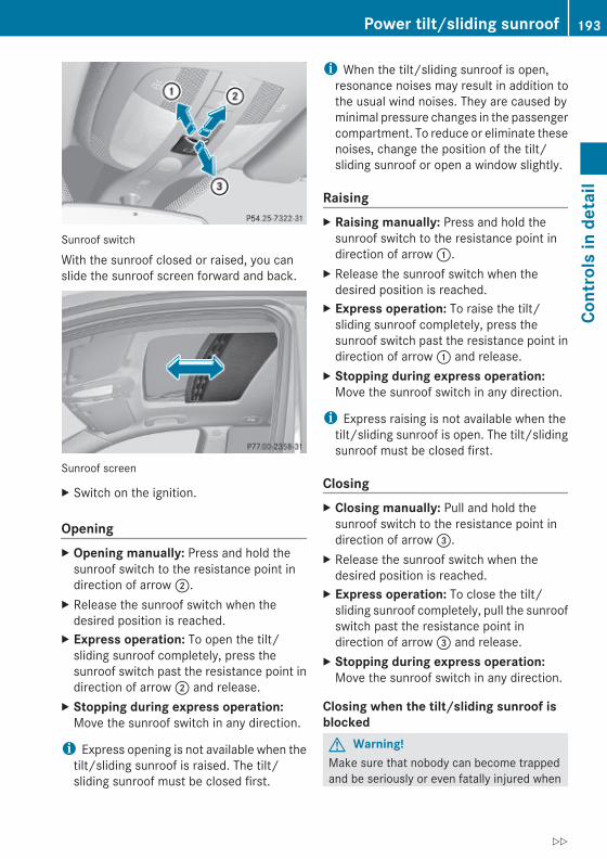
Sunroof switch
With the sunroof closed or raised, you canslide the sunroof screen forward and back.
Sunroof screen
X Switch on the ignition.
OpeningX Opening manually: Press and hold the
sunroof switch to the resistance point indirection of arrow ;.
X Release the sunroof switch when thedesired position is reached.
X Express operation: To open the tilt/sliding sunroof completely, press thesunroof switch past the resistance point indirection of arrow ; and release.
X Stopping during express operation:Move the sunroof switch in any direction.
i Express opening is not available when thetilt/sliding sunroof is raised. The tilt/sliding sunroof must be closed first.
i When the tilt/sliding sunroof is open,resonance noises may result in addition tothe usual wind noises. They are caused byminimal pressure changes in the passengercompartment. To reduce or eliminate thesenoises, change the position of the tilt/sliding sunroof or open a window slightly.
RaisingX Raising manually: Press and hold the
sunroof switch to the resistance point indirection of arrow :.
X Release the sunroof switch when thedesired position is reached.
X Express operation: To raise the tilt/sliding sunroof completely, press thesunroof switch past the resistance point indirection of arrow : and release.
X Stopping during express operation:Move the sunroof switch in any direction.
i Express raising is not available when thetilt/sliding sunroof is open. The tilt/slidingsunroof must be closed first.
ClosingX Closing manually: Pull and hold the
sunroof switch to the resistance point indirection of arrow =.
X Release the sunroof switch when thedesired position is reached.
X Express operation: To close the tilt/sliding sunroof completely, pull the sunroofswitch past the resistance point indirection of arrow = and release.
X Stopping during express operation:Move the sunroof switch in any direction.
Closing when the tilt/sliding sunroof is blockedG Warning!Make sure that nobody can become trappedand be seriously or even fatally injured when
Power tilt/sliding sunroof 193
Cont
rols
in d
etai
l
X164_AKB; 5; 31, en-USd2ureepe, Version: 2.11.8.1
2009-09-11T12:30:16+02:00 - Seite 193
Z

closing the tilt/sliding sunroof with greaterforce or without automatic reversal function.
If the movement of the tilt/sliding sunroof isblocked during the closing procedure (e.g. byice or pollution), the tilt/sliding sunroof willstop and open slightly.X Immediately after the tilt/sliding sunroof
has stopped and opened because it wasblocked, pull and hold the sunroof switchin direction of arrow = until the tilt/slidingsunroof is fully closed.The tilt/sliding sunroof closes with greaterforce.
If the tilt/sliding sunroof is blocked again andopens slightly:X Immediately after the tilt/sliding sunroof
was blocked and has opened, pull and holdthe sunroof switch in direction of arrow= until the tilt/sliding sunroof is fullyclosed.The tilt/sliding sunroof closes withoutautomatic reversal function.
G Warning!Pulling and holding the sunroof switch toclose the tilt/sliding sunroof immediatelyafter it had been blocked two times will causethe tilt/sliding sunroof to close without anyreversal function for as long as you hold thesunroof switch.
SynchronizingThe tilt/sliding sunroof must be synchronizedRafter the battery has been disconnected or
dischargedRafter a malfunctionRif the tilt/sliding sunroof does not open
smoothly
! If the tilt/sliding sunroof cannot be closedor synchronized, contact an authorizedMercedes-Benz Center or call RoadsideAssistance.
X Vehicles with SmartKey: Switch off theignition and remove the SmartKey from thestarter switch.
X Vehicles with KEYLESS-GO: Switch off theignition and open the driver’s door. Thisputs the starter switch in position 0, sameas with the SmartKey removed from thestarter switch. The driver’s door then canbe closed again.
X Remove the fuse for the tilt/sliding sunrooffrom the fuse box (Y page 355).
X Reinsert the fuse in the fuse box.X Switch on the ignition.X Press and hold the sunroof switch in
direction of arrow : (Y page 193) until thetilt/sliding sunroof is fully raised at therear.
X Keep holding the sunroof switch indirection of arrow : for approximately1 second.
X Check the express operation feature(Y page 193).If the tilt/sliding sunroof opens and closescompletely, the roof is synchronized.Otherwise repeat the above steps.
Loading and storing
Loading instructions
G Warning!Always fasten items being carried as securelyas possible. Use cargo tie-down rings andfastening materials appropriate for the weightand size of the load.In an accident, during hard braking or suddenmaneuvers, loose items will be thrown aroundinside the vehicle. This can cause injury tovehicle occupants unless the items aresecurely fastened in the vehicle.To help avoid personal injury during a collisionor sudden maneuver, exercise care whentransporting cargo. Do not pile luggage orcargo higher than the seat backrests.
194 Loading and storingCo
ntro
ls in
det
ail
X164_AKB; 5; 31, en-USd2ureepe, Version: 2.11.8.1
2009-09-11T12:30:16+02:00 - Seite 194

The cargo compartment is the preferred placeto carry objects. Always use cargo tie-downrings, and if so equipped, always use the cargonet when transporting cargo.Never drive a vehicle with the tailgate open.Deadly carbon monoxide (CO) gases mayenter vehicle interior resulting inunconsciousness and death.
Load distribution
The Gross Vehicle Weight (GVW) is the weightof the vehicle including:RfuelRtoolsRspare wheelRinstalled accessoriesRpassengersRluggage/cargoIt must never exceed the load limit and theGross Vehicle Weight Rating (GVWR) for yourvehicle. The load limit and the GVWR arespecified on the placard located on thedriver’s door B-pillar (Y page 242).In addition, the load must be distributed sothat the weight on each axle never exceeds
the Gross Axle Weight Rating (GAWR) for thefront and rear axle. The GVWR and GAWR foryour vehicle are indicated on the certificationlabel located on the driver’s door B-pillar(Y page 242).For more information, see “Tire and LoadingInformation” (Y page 242).The handling characteristics of a fully loadedvehicle depend greatly on the loaddistribution. It is therefore recommended toload the vehicle according to the illustrationshown. The heaviest items are to be placedtowards the front of the vehicle.
i The cargo compartment is the preferredplace to carry objects. The expanded cargovolume (Y page 201) should only be usedfor items which do not fit in the cargocompartment alone.
Please pay attention to and comply with thefollowing instructions when loading thevehicle and transporting cargo:RAlways place items being carried against
front or rear seat backrests, and fastenthem as securely as possible.RThe heaviest portion of the cargo should
always be kept as low as possible againstfront or rear seat backrests.
For additional safety when transporting cargowhile the rear seats are unoccupied, fastenthe outer seat belts crosswise into theopposite side buckles.
Loading and storing 195
Cont
rols
in d
etai
l
X164_AKB; 5; 31, en-USd2ureepe, Version: 2.11.8.1
2009-09-11T12:30:16+02:00 - Seite 195
Z

CarriersFor information about further carriers,contact an authorized Mercedes-BenzCenter.
G Warning!Only use carriers when the crossbars havebeen completely mounted. The left and rightroof rails are only stabilized by means of thecrossbars mounted.Follow the manufacturer’s installationinstructions. Otherwise, an improperlyattached carrier or its load could becomedetached from the vehicle.Do not exceed the maximum roof load of198 lb (90 kg).Take into consideration that when the roof isloaded, the handling characteristics aredifferent from those when operating thevehicle without the roof loaded.
Make sureRyou can raise the tilt/sliding sunroof at the
rear completelyRyou can open the tailgate completely
i The following accessories are availablefor your Mercedes-Benz:RRoof Cargo Container – Small, Medium,
or LargeRSki and Snowboard Carrier – StandardRSki and Snowboard Carrier – Deluxe
(Only in connection with correspondingadapter.)
For more information on Mercedes-Benzaccessories, contact your authorizedMercedes-Benz Center.
Roof rails
CrossbarsThe maximum roof load of any add-on roofequipment is reduced by the unladen weightof the crossbars (13.7 Ibs/6.2 kg).Installing the crossbars increases the totalvehicle height given in the “Technical data”section by 2 in (50 mm).Four keys and an hex key required forinstalling and removing are included with thecrossbars.
i The keys and the hex key are stored withthe vehicle tool kit under the cargocompartment floor (Y page 284).
i Spare parts are available as Mercedes-Benz accessories. Contact your authorizedMercedes-Benz Center.
Installing the crossbarsG Warning!Please follow these installation instructionscarefully. Caution should be exercised toavoid damage to the vehicle while installingthe crossbars. Also, be careful not to injureyourself or others while installing andadjusting the crossbars or loading items onthem.Each individual step of the installationinstructions, the warning notices, the generalsafety precautions and the instructions foruse must be followed exactly. If the crossbarsare not mounted correctly, they and the
196 Loading and storingCo
ntro
ls in
det
ail
X164_AKB; 5; 31, en-USd2ureepe, Version: 2.11.8.1
2009-09-11T12:30:16+02:00 - Seite 196

objects attached to them could come loosefrom your vehicle and cause an accident,thereby injuring you and other persons and/or causing damage to property, includingdamage to your vehicle.
G Warning!Every time the crossbars are mounted, beforeyou set off on a journey and periodicallyduring longer journeys, check all the screwson the crossbars to make sure that they aresecure, and tighten them if necessary. Repeatthese checks at regular intervals as road-surface conditions dictate, and at least afterevery 1500 miles (2500 km) of continuoususe.Otherwise, the crossbars, mountedaccessories and the objects attached to themcould come loose from the vehicle causing anaccident, thereby injuring you and otherpersons and/or causing damage to property,including damage to your vehicle.Do not use lubricant on the screws of thecrossbars. The screws could work loose andthe crossbars could become detached fromyour vehicle, together with the objectsattached to them causing an accident,thereby injuring you and other persons and/or causing damage to property, includingdamage to your vehicle.
G Warning!Only install the crossbars at the exactlocations designated on the roof rails. Thedesignated locations for the front crossbarsare between the markings engraved on theinside of the roof rails. The designatedlocations for the rear crossbars are betweenthe gaps on the roof rails.Otherwise, the crossbars, mountedaccessories and the objects attached to themcould come loose from the vehicle causing anaccident, thereby injuring you and otherpersons and/or causing damage to property,including damage to your vehicle.
G Warning!A roof load creates a greater surface areaexposed to the wind and causes the vehicleto have a higher center of gravity, therebychanging the vehicle’s driving characteristics.Accordingly, the additional weight on the roofof the vehicle can have a detrimental effecton braking, cornering and acceleration.Never exceed the maximum permissible roofload or the maximum permissible vehicleweight, even when accessories for thecrossbars (e.g. ski racks, bicycle racks, etc.)are being used. Overloading the vehicle couldresult in an accident. When calculating theweight placed on the roof please make sureto add the weight of the crossbars, accessoryracks and the load carried together.Always adapt your driving style to the road,traffic and weather conditions, and drive withadded caution when the roof is loaded.Always drive with extreme care when thecarrier is loaded. Take into consideration thatwhen the carrier is loaded, the handlingcharacteristics are different from those whenoperating the vehicle without a carrier loaded.
G Warning!Do not use accessories which have not beenapproved by Mercedes-Benz for use inconjunction with these crossbars. If non-approved accessories are used, theseaccessories and/or the objects attached tothem could come loose from the vehicle,thereby injuring you and other persons and/or causing damage to property, includingdamage to your vehicle.
! Have a second person assist you wheninstalling the crossbars. The vehicle couldotherwise be damaged.
! Objects attached to the crossbarsystem’s accessories must not be allowedto restrict the movement of the tilt/slidingsunroof. The tilt/sliding sunroof couldotherwise be damaged when it is raised.
Loading and storing 197
Cont
rols
in d
etai
l
X164_AKB; 5; 31, en-USd2ureepe, Version: 2.11.8.1
2009-09-11T12:30:16+02:00 - Seite 197
Z

: Key; Cover cap= Sticker FRONT (or REAR)? Screw for clamping clawA Clamping claw
The front and rear crossbars are of differentlengths. Please pay close attention to stickers= FRONT and REAR on the crossbars.X Unlock cover cap ; with key :.X Remove cover cap ;.
Sticker = indicating the location, FRONTor REAR, becomes visible.
X Turn screw ? counterclockwise with theincluded hex key until clamping claw A iswide open.
B Front crossbarC Rear crossbarD GapsE MarkingsF Roof rails
X Place front crossbar B between markingsE on roof rails F.
i Markings E are located on the inside ofeach roof rail, indicated by the white linesin the illustration.
? Screw for clamping clawA Clamping clawF Roof rail
X Make sure clamping claw A lies flushagainst the inside of roof rail F as shownin the illustration.If necessary, adjust clamping width ofcrossbar (Y page 199).
X Slightly tighten screw ? on both sides byturning it clockwise.
X Place rear crossbar C on roof rails F insuch a way that the clamping claws reachinto gaps D (Y page 198) on the roof rails.
X Make sure clamping claw A lies flushagainst the inside of roof rail F as shownin the illustration (Y page 198).If necessary, adjust clamping width ofcrossbar (Y page 199).
X Slightly tighten screw ? on both sides byturning it clockwise.
X On the front and rear crossbars tightenscrews ?. Observe a tightening torque of4 lb-ft (6 Nm).
G Warning!Have the tightening torque checked aftermounting the crossbars. The screws couldcome loose if they are not tightened to atorque of 4 lb-ft (6 Nm).
198 Loading and storingCo
ntro
ls in
det
ail
X164_AKB; 5; 31, en-USd2ureepe, Version: 2.11.8.1
2009-09-11T12:30:16+02:00 - Seite 198

X Attach cover caps (Y page 198) and lockthem.
X Store key and hex key back into the storagewell (Y page 284).
Adjusting the clamping widths of the crossbarsG Warning!Only install the crossbars at the exactlocations designated on the roof rails. Thedesignated locations for the front crossbarsare between the markings engraved on theinside of the roof rails. The designatedlocations for the rear crossbars are betweenthe gaps on the roof rails.Otherwise, the crossbars, mountedaccessories and the objects attached to themcould come loose from the vehicle causing anaccident, thereby injuring you and otherpersons and/or causing damage to property,including damage to your vehicle.
The clamping widths of the crossbars arefactory set for your vehicle. These clampingwidths are solely intended for the designatedpositions.Only install the crossbars at the designatedlocations and pay attention to the stickers= FRONT and REAR (Y page 198).
? Screw for clamping clawA Clamping clawG Screws for adjusting clamping width (2 in
total for each side)H Cover strip
X Pull cover strip H out of groove until yousee screws G on each end of the crossbar.
X Turn screws G on both sidescounterclockwise approximately 2rotations.
X Place the crossbar at designated locations(Y page 198) on roof rails.
X On both sides, make sure the clampingclaws A lie flush against the roof rails. Ifnecessary, pull out or push in the clampingclaws A.
X Tighten screws G. Observe a tighteningtorque of 4 lb-ft (6 Nm).The width of the clamping claws is correctlyadjusted.
G Warning!Have the tightening torque checked aftermounting the crossbars. The screws couldcome loose if they are not tightened to atorque of 4 lb-ft (6 Nm).
X Press cover strip H piece by piece intogroove of crossbar.
X Install the crossbars as described(Y page 196).
Removing the crossbars
: Key; Cover cap= Sticker FRONT (or REAR)? Screw for clamping clawA Clamping claw
Loading and storing 199
Cont
rols
in d
etai
l
X164_AKB; 5; 31, en-USd2ureepe, Version: 2.11.8.1
2009-09-11T12:30:16+02:00 - Seite 199
Z

X Unlock cover cap ; with key :.X Remove cover cap ;.X Turn screws for clamping claws A
counterclockwise until the crossbars canbe lifted from the roof rails.
Shortening the cover stripThe cover strips reduce the wind noisecaused by the crossbars. In order to installadd-on roof equipment, it may be necessaryto shorten the cover strips.
H Cover strip
X Pull cover strip H out of groove.X Attach add-on roof equipment to the
crossbars.X Place cover strip H flush against the add-
on roof equipment, and mark the end ofcrossbar on cover strip.
X Cut off cover strip H at marked location.X Press cover strip H piece by piece into
groove of the crossbar.
i Cover strips are available as Mercedes-Benz accessories. Contact your Mercedes-Benz Center.
Parcel nets
G Warning!Vehicles with Occupant Classification System(OCS)Do not place objects with a combined weightof more than 4.4 lbs (2 kg) into the parcel net
on the back of the front passenger seat.Otherwise, the OCS may not be able toproperly approximate the occupant weightcategory.
G Warning!Parcel nets are intended for storing light-weight items only, such as road maps, mail,etc.Heavy objects, objects with sharp edges, orfragile objects may not be transported in theparcel nets. In an accident, during hardbraking, or sudden maneuvers, they could bethrown around inside the vehicle and causeinjury to vehicle occupants.Parcel nets cannot protect transported goodsin the event of an accident.
Parcel nets are located in the front passengerfootwell and on each of the front seatbackrests.
Cargo tie-down ringsYour vehicle is equipped with eight cargo tie-down rings.Always follow loading instructions(Y page 194).Carefully secure cargo by applying even loadon all the cargo tie-down rings with a rope ofsufficient strength to hold down the cargo.The maximum permissible weight per cargotie-down ring is 331 lb (150 kg).
Cargo tie down rings, cargo compartment
200 Loading and storingCo
ntro
ls in
det
ail
X164_AKB; 5; 31, en-USd2ureepe, Version: 2.11.8.1
2009-09-11T12:30:16+02:00 - Seite 200

Cargo tie down rings, second-row footwell
For Information on how to fold the third-rowseats, see “Expanding cargo volume”(Y page 201).
HooksTwo hooks are located on the rearcompartment trim panels, one on each side.Use the hooks to secure light-weight itemsonly. The maximum permissible weight perhook is 9 lbs (4 kg).
Expanding cargo volumeYou can separately fold each seat of the rearpassenger compartment to expand the cargovolume.You can expand the cargo volumeRin part, i.e. folding third-row seats
(Y page 201)Rfully, i.e. folding second-row and third-row
seats (Y page 201)
G Warning!When expanding the cargo volume, alwaysfully fold the corresponding seats and, if soequipped, always use the cargo net whentransporting cargo.Unless you are transporting cargo, the seatbackrests must remain properly locked in theupright position.In an accident, during hard braking or suddenmaneuvers, loose items will be thrown aroundinside the vehicle. This can cause injury tovehicle occupants unless the items aresecurely fastened in the vehicle.Always use the cargo tie-down rings.
G Warning!Never drive a vehicle with the tailgate open.Deadly carbon monoxide (CO) gases mayenter vehicle interior resulting inunconsciousness and death.
! When the second-row seats are foldedforward, the front seats may not be movedto the rearmost position. Otherwise youcould damage the front and second-rowseats.
Expanding cargo volume in part
Folding third-row seatsThere are several ways to fold the third-rowseats.Use the left button, indicated by L, to folddown the left third-row seat.
Loading and storing 201
Cont
rols
in d
etai
l
X164_AKB; 5; 31, en-USd2ureepe, Version: 2.11.8.1
2009-09-11T12:30:16+02:00 - Seite 201
Z

Use the right button, indicated by R, to folddown the right third-row seat.Two buttons are located on the right side trimof the third-row seats.
i It is only possible to fold the third-rowseats down when the rear right door isopen.
Example, button for the left third-row seats: Button for returning third-row seats to
upright position; Button for folding the third-row seats
Two buttons are located on the passenger-side in the cargo compartment.
i It is only possible to fold the third-rowseats down when the tailgate is open.
Example, button for the right third-row seats: Button for returning third-row seats to
upright position; Button for folding the third-row seats
X Lower the head restraints of the third-rowseats completely (Y page 88).
X Remove cargo compartment cover blind(Y page 205).
X Press button ; for each side until thethird-row seats are fully folded.
If a third-row seat is not engaged properly, forexample, the message 3rd Row Of Seats-Right Not Locked appears in themultifunction display (Y page 125).X Press button ; again, until the message
disappears.
Expanding cargo volume fully
G Warning!Folded second-row seats are intended toserve as a cargo volume expansion inconjunction with folded third-row seats only.Do not fold the second-row seats and allowthird-row seat occupants to use foldedsecond-row seats as a footrest while driving.Third-row seat occupants must, like all vehicleoccupants, keep both feet on the floor in frontof their seat. Otherwise, occupants couldslide under their seat belt in a collision. Ifoccupants slide under the seat belt, it wouldapply force at the abdomen or neck. Thatcould cause serious or even fatal injuries. Donot fold the second-row seats and allow third-row seat occupants to use folded second-rowseats as a table while driving. Objects placedon folded second-row seats may come looseduring braking, vehicle maneuvers, or an
202 Loading and storingCo
ntro
ls in
det
ail
X164_AKB; 5; 31, en-USd2ureepe, Version: 2.11.8.1
2009-09-11T12:30:16+02:00 - Seite 202

accident and be thrown around the vehicleinterior. Objects thrown around the vehicleinterior may cause an accident and/orserious personal injury.
Folding second-row seats! When the second-row seats are folded
forward, the front seats may not be movedto the rearmost position. Otherwise youcould damage the front and second-rowseats.
X Lower the head restraints of the second-row seats completely (Y page 88).
X Pull strap : in direction of arrow.X Fold seat cushion ; forward.
X Pull and hold lever = in direction of arrowat resistance point.The seat backrest folds down.
X Check for secure locking by pushing andpulling on the seat backrest.
Folding third-row seatsUse the left button, indicated by L, to folddown the left third-row seat.Use the right button, indicated by R, to folddown the right third-row seat.There are several ways to fold the third-rowseats.Two buttons are located on the right side trimof the third-row seats.
i It is only possible to fold the third-rowseats down when the rear right door isopen.
Example, button for the left third-row seats: Button for returning third-row seats to
upright position; Button for folding the third-row seats
Two buttons are located on the passenger-side in the cargo compartment.
Loading and storing 203
Cont
rols
in d
etai
l
X164_AKB; 5; 31, en-USd2ureepe, Version: 2.11.8.1
2009-09-11T12:30:16+02:00 - Seite 203
Z

i It is only possible to fold the third-rowseats down when the tailgate is open.
Example, button for the right third-row seats: Button for returning third-row seats to
upright position; Button for folding the third-row seats
X Lower the head restraints of the third-rowseats completely (Y page 88).
X Remove cargo compartment cover blind(Y page 205).
X Press button ; for each side until thethird-row seats are fully folded.The cargo compartment is fully extended.
If a third-row seat is not engaged properly, forexample, the message 3rd Row Of Seats-Right Not Locked appears in themultifunction display (Y page 125).X Press button ; again, until the message
disappears.
Returning seats to their original positionG Warning!Make sure all seats are properly locked inposition before driving off. Do not drive withseats not properly locked.Never ride in a moving vehicle with the seatnot properly locked as this can be dangerous.The seat could move forward and the seatbackrest could fold. You could slide under theseat belt during braking, vehicle maneuvers,or in an accident. If you slide under it, the seatbelt would apply force at the abdomen orneck. That could cause serious or even fatalinjuries. Never ride in a moving vehicle withthe seat not properly locked as this can bedangerous. The seat could move forward andthe seat backrest could fold. You could slideunder the seat belt during braking, vehiclemaneuvers, or in an accident. If you slideunder it, the seat belt would apply force at theabdomen or neck. That could cause seriousor even fatal injuries.The seat backrest and seat belt provide thebest restraint when the wearer is in a nearlyupright position and the seat belt is properlypositioned on the body.
X Step 1: Return third-row seats to itsoriginal position (Y page 203).
204 Loading and storingCo
ntro
ls in
det
ail
X164_AKB; 5; 31, en-USd2ureepe, Version: 2.11.8.1
2009-09-11T12:30:16+02:00 - Seite 204

X Step 2: Pull and hold lever ; in directionof arrow at resistance point.
X Fold seat backrest : rearward until itengages.
X Check for secure locking by pushing andpulling on seat backrest :.
X Fold seat cushion = rearward until it locksinto position.
Cargo compartment cover blindThe cargo compartment cover blind can beinstalled behind the third-row seats or thesecond-row seats.
! With the cargo compartment cover blindinstalled, do not pile luggage higher thanthe lower edges of the rear side windows.
X Rolling out: Pull cargo compartment coverblind on handle : across the cargocompartment.
X Guide cargo compartment cover blind intomounts ; and release.
X Rolling up: Disengage cargo compartmentcover blind and guide retraction by itshandle :.
Before removing or installing cargocompartment cover blind behind the third-row seats, fold the left or right third-row seatforward (Y page 201). Afterwards, return theleft or right third-row seat into its originalposition.Before installing cargo compartment coverblind behind the second-row seats, fold thethird-row seats forward (Y page 201).
X Removing: Roll up cargo compartmentcover blind.
X Push release button =.X Pull cargo compartment cover blind ? to
the left.X Remove cargo compartment cover blind.X Installing: Remove the mount covers in the
side trims of the third-row seats wheninstalling the cargo compartment coverblind behind the second-row seats.
Mount cover behind second-row seats
Loading and storing 205
Cont
rols
in d
etai
l
X164_AKB; 5; 31, en-USd2ureepe, Version: 2.11.8.1
2009-09-11T12:30:16+02:00 - Seite 205
Z

X Press on mount cover at its upper edge asindicated by arrow.The mount cover’s lower edge flips up.
X Remove mount cover by pulling its loweredge out of the side trim.
i To avoid loss of the mount covers, insertthe mount covers into the mounts currentlynot in use.
X Make sure release button = faces up andthe handle : is to the rear before insertingthe cargo compartment cover blind.
X Place left side of cargo compartment coverblind in left mount.
X Position right side of cargo compartmentcover blind over right mount.
X Press release button = and guide cargocompartment cover blind into mount.
X Make sure cargo compartment cover blindis securely fastened.
Cargo net
G Warning!Make sure the cargo net is properly engagedat top and bottom position and the tighteningbelts are securely fastened.Never use a damaged cargo net.Always use cargo net when transportingcargo. This helps to avoid personal injury fromsmaller objects being thrown around in theoccupant compartment during a collision orsudden maneuver.The cargo net cannot prevent the movementof large, heavier objects into the passengercompartment in an accident. Such items mustbe properly secured using the cargo tie-downrings in the cargo compartment floor.Passenger use of seats behind installed cargonet is restricted because of the footwell beingtaken up by the net.
Use of the cargo net is a particularlyimportant safety factor when the vehicle isloaded higher than the top of the seat
backrests with smaller objects. For yoursafety, always use the cargo net whentransporting cargo.The cargo net can be installed behind theB-pillar or the C-pillar.
RWith the cargo volume fully expanded(Y page 202), use holders : behindB-pillars and the cargo tie-down rings in thesecond-row footwell (Y page 201).RWith the cargo volume expanded in part
(Y page 201), use holders ; behindC-pillars and the cargo tie-down ringsbehind the third-row seat backrests(Y page 200).
X Open the hook and loop fasteners on thecargo net package.
X Roll out the cargo net.X Unfold the cargo net.X Engage the upper cargo net bar.
The cargo net bar must engage audibly.
Installing the cargo net
Cargo net installed behind the C-pillar
206 Loading and storingCo
ntro
ls in
det
ail
X164_AKB; 5; 31, en-USd2ureepe, Version: 2.11.8.1
2009-09-11T12:30:16+02:00 - Seite 206

X Hang cargo net bar ; on holder : asindicated by the arrow.
X Push cargo net bar ; forward intoholder : in direction of arrow.
X Engage lower cargo net bar.The cargo net bar must engage audibly.
Pulling the cargo net tight
Belt hook attached behind the third-row seatbackrest
X Hook belt hook : into cargo tie-downring ; in direction of arrow.
X Pull tightening belt = by the loose end indirection of arrow until the cargo net ispulled tight.
X After driving a short distance, make surethe cargo net is still tight and, if necessary,pull it tight again.
Loosening the cargo net
Belt hook attached behind the third-row seatbackrest
X Loosen the tightening belt by pullingbuckle : upward in direction of arrow.
X Remove belt hook ; from cargo tie-downring =.
Removing and storing the cargo netX Take cargo net bar ; (Y page 206) out of
holder : (Y page 206).X Press the red button on the upper and lower
cargo net bar.X Fold the cargo net.X Roll up the cargo net.X Close the hook and loop fasteners on the
cargo net package.
Front storage compartments
G Warning!To help avoid personal injury during a collisionor sudden maneuver, exercise care whenstoring objects in the vehicle. Put luggage orcargo in the cargo compartment if possible.Do not pile luggage or cargo higher than theseat backrests.If so equipped, always use the cargo net whentransporting cargo. The cargo net cannotsecure hard or heavy objects.Parcel nets cannot secure hard or heavyobjects.Keep compartment lids closed. This will helpto prevent stored objects from being thrownabout and injuring vehicle occupants duringRbrakingRvehicle maneuversRan accident
Glove box Depending on vehicle equipment, an AUXsocket or a media interface is located in theglove box. For information on Audio AUXmode or on media interface, see separateCOMAND system operating instructions.
Loading and storing 207
Cont
rols
in d
etai
l
X164_AKB; 5; 31, en-USd2ureepe, Version: 2.11.8.1
2009-09-11T12:30:16+02:00 - Seite 207
Z

X Opening: Pull glove box lid release :.
X Closing: Push glove box lid ; upwardsuntil it engages.
You can lock the glove box, e.g. when thevehicle is in the shop for service.The glove box can only be locked or unlockedwith the mechanical key.
1 Glove box unlocked2 Glove box locked
Storage compartment in front center consoleIn vehicles with enhanced off-road package,the upper storage compartment contains acontrol panel (Y page 123).
X Press the front of the cover briefly.The cover opens automatically.
Front armrest storage compartment
i The Roadside Assistance button º(Y page 216) and the Information buttonE (Y page 217) are located in thestorage compartment.
X Opening storage compartment: Pullbutton : and lift up armrest.
Coin holders = are located in front of storagecompartment ;.
208 Loading and storingCo
ntro
ls in
det
ail
X164_AKB; 5; 31, en-USd2ureepe, Version: 2.11.8.1
2009-09-11T12:30:16+02:00 - Seite 208

Rear storage compartmentsDepending on vehicle equipment, yourvehicle may not be equipped with threestorage compartments in the front of the rearseats.
: Storage compartment; Storage compartment cover= Release button? Storage compartment
X Briefly press release button = on storagecompartment cover ;.The storage compartment opensautomatically.
Useful features
Cup holders
G Warning!In order to help prevent spilling liquids onvehicle occupants and/or vehicle equipment,only use containers that fit into the cupholder. Use lids on open containers and donot fill containers to a height where thecontents, especially hot liquids, could spillduring braking, vehicle maneuvers, or in anaccident. Liquids spilled on vehicle occupantsmay cause serious personal injury. Liquidsspilled on vehicle equipment may causedamage not covered by the Mercedes-BenzLimited Warranty.
When not in use, keep the cup holder closed.An open cup holder may cause injury to youor others when contacted during braking,vehicle maneuvers, or in an accident.Keep in mind that objects placed in the cupholder may come loose during braking,vehicle maneuvers, or in an accident and bethrown around in the vehicle interior. Objectsthrown around in the vehicle interior maycause an accident and/or serious personalinjury.
Cup holder in front center consoleA cup holder and a removable card/ticketholder are located in the front center console.The cup holder can be removed for cleaningpurposes.
X Removing: Hold cup holder at itsbridge ; and pull out bridge in direction ofarrow.
X Pull cup holder : out in direction of arrow.X Reinstalling: First, insert cup holder :
and then insert bridge ;.
Cup holder in rear armrest X Fold down the rear armrest.
Useful features 209
Cont
rols
in d
etai
l
X164_AKB; 5; 31, en-USd2ureepe, Version: 2.11.8.1
2009-09-11T12:30:16+02:00 - Seite 209
Z

! Do not sit on or lean your body weightagainst the armrest when it is folded down,as you could otherwise damage it.
Cup holders in third-row side trimsCup holders are located in the side trims ofthe third-row seats.
Sun visors
G Warning!Do not use the vanity mirror while driving.Keep the vanity mirrors in the sun visorsclosed while vehicle is in motion. Reflectedglare can endanger you and others.
: Sun visor; Additional sun visor= Vanity mirror lamp? Vanity mirror coverA Holder, e.g. for gas cardsB Vanity mirrorC Mounting
Glare through the windshieldX Flip sun visor : down when you
experience glare.
Glare through a door windowX Close vanity mirror cover ? if opened.X Disengage sun visor : from mounting C.X Pivot sun visor : to the side.
X Adjust sun visor : by pushing or pulling indirection of arrows.
X Flip down additional sun visor ; when youexperience additional glare through thewindshield.
210 Useful featuresCo
ntro
ls in
det
ail
X164_AKB; 5; 31, en-USd2ureepe, Version: 2.11.8.1
2009-09-11T12:30:16+02:00 - Seite 210

Vanity mirrorVanity mirror lamp = only functions whensun visor : is engaged in mounting C.X Flip sun visor down.X Lift up vanity mirror cover ?.
Vanity mirror lamp = comes on.
Rear panorama roof sunshadeThe rear panorama roof sunshade over thethird-row seats prevents the sun from shiningdirectly into the vehicle.You can open and close the sunshade byhand.
! Always guide the sunshade. Do not let itsnap back abruptly, as it could bedamaged.
X Extending: Grasp on handle = and insertclips ; into mounting :.The third-row sunshade engages.
X Retracting: Press on button ? todisengage the third-row sunshade frommounting :.
Ashtrays
Center console ashtray i A storage compartment is located under
the ashtray insert.
! The storage compartment is not heat-proof. Therefore, do not stub cigarettes inthe storage compartment.
X Opening: Press cover ; briefly.X Removing ashtray insert: Grab ashtray
insert : on the sides and pull it outupwards.
X Reinstalling ashtray insert: Installashtray insert :.
X Closing: Push cover ;.
Rear center console ashtray ! Close the ashtray when not in use and
before folding the second-row seats.Otherwise you could damage the ashtray.
X Opening: Press cover ; briefly.X Removing ashtray insert: Grab ashtray
insert : on the sides and pull it outupwards.
Useful features 211
Cont
rols
in d
etai
l
X164_AKB; 5; 31, en-USd2ureepe, Version: 2.11.8.1
2009-09-11T12:30:16+02:00 - Seite 211
Z

X Reinstalling ashtray insert: Installashtray insert :.
X Closing: Push cover ;.
Cigarette lighter
G Observe Safety notes, see page 55.
G Warning!Never touch the heating element or sides ofthe lighter; they are extremely hot. Hold theknob only.Make sure any children traveling with you donot injure themselves or start a fire with thehot cigarette lighter.
If the engine is off and the cigarette lighter isbeing used extensively, the vehicle batterymay become discharged.X Open the ashtray (Y page 211).
X Switch on the ignition.X Push in cigarette lighter :.
Cigarette lighter : will pop outautomatically when hot.
X Take out cigarette lighter :.X Reinsert cigarette lighter : in its socket
after use.
! The lighter socket can be used toaccommodate 12V DC electricalaccessories (up to a maximum of 180 W)designed for use with the standard“cigarette lighter” plug type. Keep in mind,however, that connecting accessories to
the lighter socket (for example extensiveconnecting and disconnecting, or usingplugs that do not fit properly) can damagethe lighter socket. With the socketdamaged, the lighter may not functionproperly any longer.
! The cigarette lighter is not designed foruse with the electric air pump. Use thepower outlet in the second-row footwell forelectric air pump operation.
Power outletsi You can use the power outlets even if the
ignition is switched off.An emergency shut-off feature is designedto prevent the vehicle’s on-board voltagefrom dropping below a minimum level. Ifthe on-board voltage drops to thisminimum level, the power outlets areautomatically switched off, to helppreserve engine starting power.
12V Power outlets! If you use all power outlets in the vehicle,
make sure that the maximum currentdrawn does not exceed 55 A.
! The power outlets in the front passengerfootwell and cargo compartment are notdesigned for use with the electric air pump.Use the power outlet in the second-rowfootwell for electric air pump operation.
The power outlets can be used toaccommodate 12V DC electrical accessories(e.g. mobile phone chargers, auxiliary lamps)up to a maximum of 20 A (240 W).
212 Useful featuresCo
ntro
ls in
det
ail
X164_AKB; 5; 31, en-USd2ureepe, Version: 2.11.8.1
2009-09-11T12:30:16+02:00 - Seite 212

Front passenger footwell
Second-row footwell
Cargo compartment
115V AC Socket
G Warning!The 115V AC socket operates at high voltage.Use the 115V AC socket in the vehicle withthe same caution and prudence that youexercise when using power outlets at home.Keep any fluids away from the 115V ACsocket. Do not clean the socket with fluids or
tapered objects. Keep the 115V AC socketcover in the closed position, when not in use.Otherwise, you could suffer an electric shockand be seriously or even fatally injured.
G Warning!A device that you connect must have asuitable plug that complies with U.S.standards. Never pull on the cable to unpluga plug from the 115V AC socket. Do not usea damaged connection cable. The 115V ACsocket may not be connected to another115V AC power source. Do not use convertersto a grounding plug with the 115V AC socket.This could cause serious personal injury toyou and/or others.
G Warning!If the 115V AC socket is damaged or torn outof the trim, do not use or touch the 115V ACsocket. Using a 115V AC socket that isdamaged or torn out of the trim could causeserious personal injury to you and/or others.
The 115V AC socket : provides analternating current of 115 volts, whichenables you to connect small electricaldevices with a combined received power of150 W at most. You can connect smalldevices such as game consoles, mobilephone chargers, laptops, etc.
Useful features 213
Cont
rols
in d
etai
l
X164_AKB; 5; 31, en-USd2ureepe, Version: 2.11.8.1
2009-09-11T12:30:16+02:00 - Seite 213
Z

Prerequisites for operation:RThe 12V power outlets in the second-row
footwell and cargo compartment(Y page 212) are operational.RThe plug of the small device must be
inserted fully into 115V AC socket :.RThe on-board voltage of the vehicle is within
the permissible voltage range.RThe specified wattage of the small device
is identical or lower than the maximumpermissible wattage (150 W) of the 115VAC socket :.
X Operation: Open cover =.X Insert the plug of the small device into
115V AC socket :.LED ; comes on.
If LED ; does not come on, refer to thesection on possible nonoperation causes.X Switching off: Pull the plug out of 115V AC
socket :.Do not pull on the cable.
X Close cover =.Possible nonoperation causes:RThe on-board voltage of the vehicle is not
within the permissible voltage range.X Start the engine.
RThe temperature of the DC/AC inverter istemporarily too high.X Pull the plug of the small device out of
115V AC socket : and plug it in againafter waiting a few minutes.
RSome small devices have a continuouspower rating of less than 150 W but a veryhigh switch-on current. Such devices willnot operate. When connecting such adevice, 115V AC socket : will not providepower.
If LED ; still does not come on, contact anauthorized Mercedes-Benz Center.
Tele Aid! In order to activate the Tele Aid system, a
subscriber agreement must be completed.To ensure your system is activated andoperational, please press Informationbutton E to perform the acquaintancecall. Failure to complete either of thesesteps may result in a system that is notactivated.If you have any questions regardingactivation, please call the CustomerAssistance Center at1-800-FOR-MERCedes (1-800-367-6372)(USA only) or 1-888-923-8367 (Canadaonly).
Shortly after the completion of your Tele Aidacquaintance call, you will receive a user IDand password in the mail. You may use thispassword to access the Tele Aid section in“Owner’s Online” at www.mbusa.com (USAonly). The “My Tele Aid” section will give youaccess to account information, remote doorunlock and more.The Tele Aid system is available ifRit has been activated and is operational.
Activation requires a subscription formonitoring services, connection andcellular air timeRvehicle battery power is availableRthe relevant cellular phone network and
GPS signals are available and pass theinformation on to the Customer AssistanceCenter
i Location of the vehicle on a map is onlypossible if the vehicle is able to receivesignals from the GPS satellite network andpass the information on to the CustomerAssistance Center.
The Tele Aid system(Telematic Alarm Identification on Demand)
214 Useful featuresCo
ntro
ls in
det
ail
X164_AKB; 5; 31, en-USd2ureepe, Version: 2.11.8.1
2009-09-11T12:30:16+02:00 - Seite 214

The Tele Aid system consists of three typesof response:RAutomatic and manual emergencyRRoadside AssistanceRInformation
To adjust the speaker volume during a TeleAid call do the following:X Press button W or X on the
multifunction steering wheel.orX Use the adjustment button on your
COMAND system.Be sure to check “Owner’s Online” atwww.mbusa.com (USA only) for moreinformation and a description of all availablefeatures.
System self-test The system performs a self-test after youhave switched on the ignition.
G Warning!A malfunction in the system has beendetected if any or all of the followingconditions occur:RThe indicator lamp in the SOS button does
not come on during the system self-test.RThe indicator lamp in Roadside Assistance
button º does not come on during thesystem self-test.RThe indicator lamp in Information buttonE does not come on during the systemself-test.RThe indicator lamp in the SOS button,
Roadside Assistance button º, orInformation button E remainsilluminated constantly in red after thesystem self-test.RThe message Tele Aid Inoperative orTele Aid Not Activated appears in themultifunction display after the system self-test
If a malfunction is indicated as outlined above,the system may not operate as expected. Incase of an emergency, help will have to besummoned by other means.Have the system checked at the nearestMercedes-Benz Center or contact theCustomer Assistance Center at1-800-FOR-MERCedes (1-800-367-6372)(USA only) or 1-888-923-8367 (Canada only)as soon as possible.
Emergency calls ! In order to activate the Tele Aid system, a
subscriber agreement must be completed.To ensure your system is activated andoperational, please press Informationbutton E to perform the acquaintancecall. Failure to complete either of thesesteps may result in a system that is notactivated.If you have any questions regardingactivation, please call the CustomerAssistance Center at1-800-FOR-MERCedes (1-800-367-6372)(USA only) or 1-888-923-8367 (Canadaonly).
An emergency call is initiated automaticallyfollowing an accident in which the EmergencyTensioning Devices (ETDs) or air bags havedeployed.
i An automatically initiated Tele Aidemergency call cannot be canceled.
An emergency call can also be initiatedmanually (Y page 216).Once the emergency call is in progress, theindicator lamp in the SOS button will begin toflash. The message Connecting Callappears in the multifunction display and theCOMAND system is muted. When theconnection is established, the messageCall Connected appears in themultifunction display.All information relevant to the emergency,such as the location of the vehicle
Useful features 215
Cont
rols
in d
etai
l
X164_AKB; 5; 31, en-USd2ureepe, Version: 2.11.8.1
2009-09-11T12:30:16+02:00 - Seite 215
Z

(determined by the GPS satellite locationsystem), vehicle model, identification numberand color are generated.A voice connection between the CustomerAssistance Center and the occupants of thevehicle will be established automatically soonafter the emergency call has been initiated.The Customer Assistance Center will attemptto determine the nature of the emergencymore precisely, provided they can speak toan occupant of the vehicle.
i If no vehicle occupant responds, anambulance will be sent to the vehicleimmediately.
G Warning!If the indicator lamp in the SOS button isflashing continuously and there was no voiceconnection to the Customer AssistanceCenter established, then the Tele Aid systemcould not initiate an emergency call (e.g. therelevant cellular phone network is notavailable).The message Call Failed appears in themultifunction display for approximately10 seconds.Should this occur, assistance must besummoned by other means.
i The “911” emergency call system is apublic service. Using it without due causeis a criminal offense.
Initiating an emergency call manually
X Briefly press on cover : to open.X Press SOS button ; briefly.
The indicator lamp in SOS button ; willflash until the emergency call is concluded.
X Wait for a voice connection to theCustomer Assistance Center.
X Close cover : after the emergency call isconcluded.
G Warning!If you feel at any way in jeopardy when in thevehicle (e.g. smoke or fire in the vehicle,vehicle in a dangerous road location), pleasedo not wait for voice contact after you havepressed the emergency button. Carefullyleave the vehicle and move to a safe location.The Customer Assistance Center willautomatically contact local emergencyofficials with the vehicle’s approximatelocation if they receive an automatic SOSsignal and cannot make voice contact with thevehicle occupants.
X Terminating calls: Press button ~ onthe multifunction steering wheel.
orX Press the respective button for ending a
telephone call on the COMAND system.
Roadside Assistance button X Open the front armrest storage
compartment (Y page 208).
216 Useful featuresCo
ntro
ls in
det
ail
X164_AKB; 5; 31, en-USd2ureepe, Version: 2.11.8.1
2009-09-11T12:30:16+02:00 - Seite 216

X Press and hold Roadside Assistancebutton : for longer than 2 seconds.A call to a Mercedes-Benz RoadsideAssistance dispatcher will be initiated. Theindicator lamp in Roadside Assistancebutton : will flash while the call is inprogress. The message Connecting Call will appear in the multifunctiondisplay and the COMAND system is muted.
When the connection is established, themessage Call Connected appears in themultifunction display. The Tele Aid system willtransmit data generating the vehicleidentification number, model, color andlocation (subject to availability of cellular andGPS signals).
i The COMAND system display indicatesthat a Tele Aid call is in progress. While thecall is connected you can change to thenavigation menu by pressing the NAVIbutton on the COMAND system. Spokencommands are not available.
A voice connection between the RoadsideAssistance dispatcher and the occupants ofthe vehicle will be established.X Describe the nature of the need for
assistance.The Mercedes-Benz Roadside Assistancedispatcher will either dispatch a qualifiedMercedes-Benz technician or arrange to towyour vehicle to the nearest authorizedMercedes-Benz Center. For services such aslabor and/or towing, charges may apply.Refer to the Roadside Assistance manual formore information.Sign and Drive services (USA only):Services such as a jump start, a few gallonsof fuel or the replacement of a flat tire withthe vehicle spare wheel are obtainable at nocharge.
i If the indicator lamp in RoadsideAssistance button : is flashingcontinuously and there was no voiceconnection to the Customer AssistanceCenter established, then the Tele Aid
system could not initiate a RoadsideAssistance call (e.g. the relevant cellularphone network is not available). Themessage Call Failed appears in themultifunction display.
X Terminating calls: Press button ~ onthe multifunction steering wheel.
orX Press the respective button for ending a
telephone call on the COMAND system.
Information button X Open the front armrest storage
compartment (Y page 208).
X Press and hold Information button : forlonger than 2 seconds.A call to the Customer Assistance Centerwill be initiated. The indicator lamp inInformation button : will flash while thecall is in progress. The messageConnecting Call will appear in themultifunction display and the COMANDsystem is muted.
When the connection is established, themessage Call Connected appears in themultifunction display. The Tele Aid system willtransmit data generating the vehicleidentification number, model, color andlocation (subject to availability of cellular andGPS signals).
i The COMAND system display indicatesthat a Tele Aid call is in progress. While thecall is connected you can change to the
Useful features 217
Cont
rols
in d
etai
l
X164_AKB; 5; 31, en-USd2ureepe, Version: 2.11.8.1
2009-09-11T12:30:16+02:00 - Seite 217
Z

navigation menu by pressing the NAVIbutton on the COMAND system. Spokencommands are not available.
A voice connection between the CustomerAssistance Center representative and theoccupants of the vehicle will be established.Information regarding the operation of yourvehicle, the nearest authorized Mercedes-Benz Center or Mercedes-Benz USA productsand services is available to you.For more details concerning the Tele Aidsystem, please visit www.mbusa.com (USAonly), log in to “Owner’s Online” and visit the“My Tele Aid” section to learn more.
i If the indicator lamp in Informationbutton : is flashing continuously andthere was no voice connection to theCustomer Assistance Center established,then the Tele Aid system could not initiatean Information call (e.g. the relevantcellular phone network is not available).The message Call Failed appears in themultifunction display.
X Terminating calls: Press button ~ onthe multifunction steering wheel.
orX Press the respective button for ending a
telephone call on the COMAND system.
Call priorityIf other service calls such as a RoadsideAssistance call or Information call are active,an emergency call is still possible. In thiscase, the emergency call will take priority andoverride all other active calls.The indicator lamp in the respective buttonflashes until the call is concluded. Automaticinitiated emergency calls can only beterminated by a Customer Assistance Centerrepresentative. All other calls can beterminated by pressing button ~ on themultifunction steering wheel or therespective button for ending a telephone callon the COMAND system.
i When a Tele Aid call has been initiated,the COMAND system audio is muted. Themobile phone is no longer connected to theCOMAND system. If you must use thisphone, we recommend that you use it onlywith the vehicle at a standstill in a safelocation.
Destination Download to the COMAND systemi The components and operating principles
of the COMAND system can be found in theseparate COMAND system operatinginstructions.
Destination Download allows you access to adatabase of over 10 million points of interest(POIs) that can be downloaded to yourvehicle’s navigation system. If you know thedestination, the address can be downloaded,or can be provided with points of interestsnear your location.
Route guidanceYou will be prompted to confirm that routeguidance to the entered address is to bestarted.X Select Yes using button = or ; on
the COMAND system.X Press button 9 on the COMAND system
to confirm.The system calculates the route andsubsequently starts the route guidance to thedefined address.
i If you select No, you can save the addressto your address book.
i The Destination Download feature isavailable if the relevant mobile phonenetwork is available and data connection ispossible.
Search & Send “Search & Send” is a navigation destinationaddress entry service. For more information
218 Useful featuresCo
ntro
ls in
det
ail
X164_AKB; 5; 31, en-USd2ureepe, Version: 2.11.8.1
2009-09-11T12:30:16+02:00 - Seite 218

on “Search & Send”, refer to separateCOMAND system operating instructions.
Remote door unlock In case you have locked your vehicleunintentionally (e.g. SmartKey inside vehicle),and the reserve SmartKey is not available:X Contact the Customer Assistance Center
at 1-800-FOR-MERCedes(1-800-367-6372) (USA only) or1-888-923-8367 (Canada only).You will be asked to provide your password.
X Then return to your vehicle at the timearranged and pull the tailgate recessedhandle (Y page 75) for a minimum of20 seconds until the indicator lamp in theSOS button is flashing.The message Connecting Call appears inthe multifunction display.
As an alternative, you may unlock the vehiclevia Internet in the “My Tele Aid” section of“Owner’s Online”, using your ID and password(USA only).
i The remote door unlock feature isavailable if the relevant cellular phonenetwork is available.The SOS button will flash and the messageCall Connected will appear in themultifunction display to indicate receipt ofthe door unlock command.If the tailgate recessed handle was pulledfor more than 20 seconds before doorunlock authorization was received by theCustomer Assistance Center, you mustwait 15 minutes before pulling the tailgaterecessed handle again.
Stolen Vehicle Recovery Services In the event your vehicle was stolen:X Report the incident to the police.
The police will issue a numbered incidentreport.
X Pass this number on to the CustomerAssistance Center along with yourpassword.The Customer Assistance Center will thenattempt to covertly contact the vehicle’sTele Aid system. Once the vehicle islocated, the Customer Assistance Centerwill contact the local law enforcement andyou. The vehicle’s location will only beprovided to law enforcement.
i If the anti-theft alarm stays on for morethan 30 seconds, the Tele Aid system willnotify the Customer Assistance Centerautomatically.
Garage door openerThe integrated remote control can operate upto three separately controlled devicescompatible with HomeLink® or some othersystems.
G Warning!Before programming the integrated remotecontrol to a garage door opener or gateoperator, make sure people and objects areout of the way of the device to preventpotential harm or damage. Whenprogramming a garage door opener, the doormoves up or down. When programming a gateoperator, the gate opens or closes.Do not use the integrated remote control withany garage door opener that lacks safety stopand reverse features as required by U.S.federal safety standards (this includes anygarage door opener model manufacturedbefore April 1, 1982). A garage door thatcannot detect an object - signaling the doorto stop and reverse - does not meet currentU.S. federal safety standards.
Useful features 219
Cont
rols
in d
etai
l
X164_AKB; 5; 31, en-USd2ureepe, Version: 2.11.8.1
2009-09-11T12:30:16+02:00 - Seite 219
Z

When programming a garage door opener,park vehicle outside the garage.Do not run the engine while programming theintegrated remote control. Inhalation ofexhaust gas is hazardous to your health. Allexhaust gas contains carbon monoxide (CO),and inhaling it can cause unconsciousnessand possible death.
Interior rear view mirror with integrated remotecontrol
Hand-held remote control A is not part of thevehicle equipment.
Programming the integrated remote controlX Step 1: Switch on the ignition.X Step 2: If you have previously programmed
a signal transmitter button and wish toretain its programming, proceed to step 3.
orX If you are programming the integrated
remote control for the first time, press andhold the two outer signal transmitterbuttons ; and ? and release them whenindicator lamp : begins to flash afterapproximately 20 seconds.Do not hold the buttons for longer than30 seconds.This procedure erases any previoussettings for all three channels andinitializes the memory. If you later wish toprogram a second and/or third hand-heldtransmitter to the remaining two signal
transmitter buttons, do not repeat this stepand begin directly with step 3.
X Step 3: Hold the end of hand-held remotecontrol A of the device you wish to trainapproximately 2 to 12 in (5 to 30 cm) awayfrom the signal transmitter button (;, =or ?) to be programmed, while keepingindicator lamp : in view.
X Step 4: Using both hands, simultaneouslypress hand-held remote control button Band the desired signal transmitter button(;, = or ?). Do not release the buttonsuntil step 5 is completed.Indicator lamp : will flash, first slowly andthen rapidly.
i Indicator lamp : flashes immediatelythe first time the signal transmitter buttonis programmed. If this button has alreadybeen programmed, the indicator lamp willstart flashing after 20 seconds.
X Step 5: After indicator lamp : changesfrom a slow to a rapidly flashing light,release the hand-held remote controlbutton and the signal transmitter button.
X Step 6: Press and hold the just-trainedsignal transmitter button (;, = or ?) andobserve indicator lamp :.If indicator lamp : stays on constantly,programming is complete and your deviceshould activate when the respective signaltransmitter button (;, = or ?) is pressedand released.
i If indicator lamp : flashes rapidly forapproximately 2 seconds and then turns toa constant light, continue withprogramming steps 8 through 12 as yourgarage door opener may be equipped withthe “rolling code” feature.
X Step 7: To program the remaining twosignal transmitter buttons, repeat the stepsabove starting with step 3.
220 Useful featuresCo
ntro
ls in
det
ail
X164_AKB; 5; 31, en-USd2ureepe, Version: 2.11.8.1
2009-09-11T12:30:16+02:00 - Seite 220

Rolling code programmingTo train a garage door opener (or other rollingcode devices) with the rolling code feature,follow these instructions after completing the“Programming” portion (steps 1 through 6) ofthis text. For your convenience and tocomplete the procedure faster, you mightwant to have someone assist you.X Step 8: Locate the “training” button on the
garage door opener motor head unit.
i Exact location and color of the button mayvary by garage door opener brand.Depending on manufacturer, the “training”button may also be referred to as “learn” or“smart” button. If there is difficulty locatingthe transmitting button, refer to the garagedoor opener Operator’s Manual.
X Step 9: Press the “training” button on thegarage door opener motor head unit.The “training light” is activated.You have 30 seconds to initiate thefollowing two steps.
X Step 10: Return to the vehicle and firmlypress, hold for 2 seconds and release theprogrammed signal transmitter button (;,= or ?).
X Step 11: Press, hold for 2 seconds andrelease same signal transmitter button asecond time to complete the trainingprocess.
i Some garage door openers (or otherrolling code equipped devices) may requireyou to press, hold for 2 seconds andrelease the same signal transmitter buttona third time to complete the trainingprocess.
X Step 12: Confirm the garage dooroperation by pressing the programmedsignal transmitter button (;, = or ?).
X Step 13: To program the remaining twosignal transmitter buttons, repeat the stepsabove starting with step 3.
Gate operator/Canadian programmingCanadian radio-frequency laws requiretransmitter signals to “time-out” (or quit)after several seconds of transmission whichmay not be long enough for the integratedsignal transmitter to pick up the signal duringprogramming. Similar to this Canadian law,some U.S. gate operators are designed to“time-out” in the same manner.If you live in Canada or if you are havingdifficulties programming a gate operator(regardless of where you live) by using theprogramming procedures, replace step 4 withthe following:X Step 4: Press and hold the signal
transmitter button (;, = or ?). Do notrelease this button until it has beensuccessfully trained.
X While still holding down the signaltransmitter button (;, = or ?), “cycle”your hand-held remote control button Bas follows: Press and hold button B for2 seconds, then release it for 2 seconds,and again press and hold it for 2 seconds.Repeat this sequence on the hand-heldremote control until the frequency signalhas been learned.Upon successful training, indicatorlamp : will flash slowly and then rapidlyafter several seconds.
X Proceed with programming step 5 andstep 6 to complete.
i Upon completion of programming theintegrated remote control, make sure youretain the hand-held remote control thatcame with the garage door opener, gateoperator or other device. You may need itfor use in other vehicles, for futureprogramming of an integrated remotecontrol, or simply for continued use as ahand-held remote control to operate therespective device in other situations.
Useful features 221
Cont
rols
in d
etai
l
X164_AKB; 5; 31, en-USd2ureepe, Version: 2.11.8.1
2009-09-11T12:30:16+02:00 - Seite 221
Z

Reprogramming a single signal transmitter buttonTo program a device using a signaltransmitter button previously trained, followthese steps:X Switch on the ignition.X Press and hold the desired signal
transmitter button (;, = or ?). Do notrelease the button.Indicator lamp : will begin to flash after20 seconds.
X Without releasing the signal transmitterbutton, proceed with programming startingwith step 3.
Operation of integrated remote controlX Switch on the ignition.X Select and press the appropriate
integrated signal transmitter button (;,= or ?) to activate the remote controlleddevice.The integrated remote control transmittercontinues to send the signal as long as thebutton is pressed – up to 20 seconds.
Erasing the integrated remote control memoryi If you sell your vehicle, erase the codes of
all three channels.
X Switch on the ignition.X Simultaneously press and hold outer signal
transmitter buttons ; and ?, forapproximately 20 seconds, until indicatorlamp : flashes rapidly. Do not hold forlonger than 30 seconds.The codes of all three channels are erased.
Programming tipsIf you are having difficulty programming theintegrated remote control, here are somehelpful tips:RCheck the frequency of hand-held remote
control A (typically located on the reverseside of the remote). The integrated remotecontrol is compatible with radio-frequencydevices operating between 280-390 MHz.RPut a new battery in hand-held remote
control A. This will increase the likelihoodof the hand-held remote control sending astronger and more accurate signal to theintegrated remote control.RWhile performing step 3, hold hand-held
remote control A at different lengths andangles from the signal transmitter button(;, = or ?) you are programming.Attempt varying angles at the distance of 2to 12 inches (5 to 30 cm) away or the sameangle at varying distances.RIf another hand-held remote control is
available for the same device, try theprogramming steps again using that otherhand-held remote control. Make sure newbatteries are in the hand-held remotecontrol before beginning the procedure.RStraighten the antenna wire from the
garage door opener assembly. This mayhelp improve transmitting and/or receivingsignals.
i Certain types of garage door openers areincompatible with the integrated remotecontrol. If you should experience furtherdifficulties with programming theintegrated remote control, contact anauthorized Mercedes-Benz Center, or callthe Mercedes-Benz Customer AssistanceCenter (USA only) at1-800-FOR-MERCedes (1-800-367-6372),or the HomeLink® Hotline (USA only) at1-800-355-3515, or the Customer Service(Canada only) at 1-800-387-0100.
222 Useful featuresCo
ntro
ls in
det
ail
X164_AKB; 5; 31, en-USd2ureepe, Version: 2.11.8.1
2009-09-11T12:30:16+02:00 - Seite 222

i USA only:This device complies with Part 15 of theFCC Rules. Operation is subject to thefollowing two conditions:1. This device may not cause harmful
interference, and2. this device must accept any
interference received, includinginterference that may cause undesiredoperation.
Any unauthorized modification to thisdevice could void the user’s authority tooperate the equipment.
i Canada only:This device complies with RSS-210 ofIndustry Canada. Operation is subject tothe following two conditions:1. This device may not cause interference,
and2. this device must accept any
interference received, includinginterference that may cause undesiredoperation of the device.
Any unauthorized modification to thisdevice could void the user’s authority tooperate the equipment.
CompassX Calling up the compass: Press buttonV or U on the multifunction steeringwheel repeatedly until the off-road menuappears in the multifunction display.The compass displays the direction intowhich the vehicle is currently traveling: N,NE, E, SE, S, SW, W, or NW.
Floormats
G Warning!Whenever you are using floormats, make surethere is enough clearance and that thefloormats are securely fastened.Floormats should always be securely fastenedusing the fastening equipment.Before driving off, check that the floormatsare securely in place and adjust them ifnecessary. A loose floormat could slip andhinder proper functioning of the pedals.Do not place several floormats on top of eachother as this may impair pedal movement.
X Move the driver’s seat or front passengerseat as far to the rear as possible.
X Removing: Pull floormat off of retainerpins :.
X Installing: Press floormat eyelets ; ontoretainer pins :.
Infrared reflecting windshieldInfrared reflecting glass reduces the amountof radiated heat entering the vehicle interiorthrough the windows.The infrared reflecting glass also prevents thetransmission of signals through the glass byin-vehicle electronic devices, e.g. electronictoll collection devices.
Useful features 223
Cont
rols
in d
etai
l
X164_AKB; 5; 31, en-USd2ureepe, Version: 2.11.8.1
2009-09-11T12:30:16+02:00 - Seite 223
Z

To allow the use of these devices in thevehicle, infrared transparent areas : areplaced in the windshield.
Seat cover under third-row seatsIf something falls under the third-row seats,you can remove the seat cover in order toreach under the seats.
Example passenger side
X Removing: Fold the respective seathalfway in or out (Y page 201).
X Reach into the recess in the seat cover.X Pull the seat cover in direction of arrow.X Remove the seat cover to reach under the
seats.X Installing: Fold the seat halfway in or out
(Y page 201).X Put the seat cover back into place using the
guide pins.
X Press the seat cover down until it engages.X Make sure the seat cover is engaged
properly by folding the seat all the way inand out.
224 Useful featuresCo
ntro
ls in
det
ail
X164_AKB; 5; 31, en-USd2ureepe, Version: 2.11.8.1
2009-09-11T12:30:16+02:00 - Seite 224

Vehicle equipment ............................ 226The first 1000 miles (1500 km) ....... 226At the gas station ............................. 226Engine compartment ........................ 228Tires and wheels ............................... 233Winter driving ................................... 257Driving instructions .......................... 259Maintenance ...................................... 273Vehicle care ....................................... 275
225
Oper
atio
n
X164_AKB; 5; 31, en-USd2ureepe, Version: 2.11.8.1
2009-09-11T12:30:16+02:00 - Seite 225

Vehicle equipment
i This Operator’s Manual describes allfeatures, standard or optional, potentiallyavailable for your vehicle at the time ofpurchase. Please be aware that yourvehicle might not be equipped with allfeatures described in this manual.
The first 1000 miles (1500 km)
The more cautiously you treat your vehicleduring the break-in period, the more satisfiedyou will be with its performance later on.RDrive your vehicle during the first
1 000 miles (1 500 km) at varying butmoderate vehicle and engine speeds.RDuring this period, avoid heavy loads (full
throttle driving) and excessive enginespeeds (no more than 2/3 of maximum rpmin each gear).RAvoid accelerating by kickdown.RDo not attempt to slow the vehicle down by
shifting to a lower gear using the gearselector lever.RSelect gear ranges 3, 2 or 1 (Y page 118)
only when driving at moderate speeds (forhill driving).
After 1 000 miles (1 500 km) you maygradually increase vehicle and engine speedsto the permissible maximum.All of the above instructions, as may apply toyour vehicle type, also apply when driving thefirst 1 000 miles (1 500 km) after the engine,the transfer case, the center differential orthe rear differential have been replaced.
i Always obey applicable speed limits.
At the gas station
Refueling
G Warning!Gasoline and diesel fuels are highly flammableand poisonous. They burn violently and cancause serious injury.Never allow sparks, flames or smokingmaterials near gasoline or diesel fuel!Turn off the engine before refueling.Whenever you are around gasoline or dieselfuel, avoid inhaling fumes and any skin orclothing contact. Extinguish all smokingmaterials.Direct skin contact with fuels and theinhalation of fuel vapors are damaging yourhealth.
G Warning!Overfilling of the fuel tank may createpressure in the system which could cause agas discharge. This could cause the gas tospray back out when removing the fuel pumpnozzle, which could cause personal injury.
G Warning!Do not fill diesel tanks with gasoline. Do notmix diesel fuel with gasoline. Otherwise thefuel system and engine could be damaged. Inaddition, the vehicle could catch fire.
! Never refuel vehicles with gasoline enginewith diesel fuel. Never refuel vehicles withdiesel engine with gasoline. Even smallamounts of incorrect fuel will damage thefuel system and engine. Damage resultingfrom the use of non-approved fuels or fueladditives or resulting from mixing gasolinewith diesel fuel or vice versa is not coveredby the Mercedes-Benz Limited Warranty.
! If you have accidentally filled the tankwith incorrect or non-approved fuel, do notswitch on the ignition. Otherwise theincorrect or non-approved fuel will get intothe fuel lines. The fuel system must be
226 At the gas stationOp
erat
ion
X164_AKB; 5; 31, en-USd2ureepe, Version: 2.11.8.1
2009-09-11T12:30:16+02:00 - Seite 226
drained completely. Contact an authorizedMercedes-Benz Center to have the fuelsystem drained completely.
! Gasoline engine:To prevent damage to the catalyticconverters, only use premium unleadedgasoline in this vehicle.Any noticeable irregularities in engineoperation should be repaired promptly.Otherwise, excessive unburned fuel mayreach the catalytic converter, causing it tooverheat and potentially start a fire.
! Diesel engine:When filling the diesel fuel tank using fuelcontainers, place a filling filter, a suedecloth or a clean flannel cloth as a filter.Otherwise, particles from the fuel containercould clog the fuel lines and/or the dieselinjection system.
! Diesel engine:The engine is more susceptible to wear anddamage if you useRmarine diesel fuelRheating oilRadditivesThe exhaust aftertreatment device will beseriously damaged if you use any otherdiesel fuel than ULTRA-LOW SULFURHIGHWAY DIESEL FUEL (ULSD, 15 ppmSULFUR MAXIMUM).The use of such non-approved fuels and/orspecial additives is not covered by theMercedes-Benz Limited Warranty.
i Gasoline engine:Only use premium unleaded gasoline witha minimum Posted Octane Rating of 91(average of 96 RON/86 MON).Information on gasoline quality cannormally be found on the fuel pump. Pleasecontact gas station personnel in caselabels on the pump cannot be found.
For more information on gasoline, see“Premium unleaded gasoline (gasolineengine)” (Y page 371), see “Fuelrequirements” (Y page 371), or contact anauthorized Mercedes-Benz Center, or visitwww.mbusa.com (USA only).
i Diesel engine:Only use commercially available vehicularULTRA-LOW SULFUR HIGHWAY DIESELFUEL (ULSD, 15 ppm SULFUR MAXIMUM).Information on diesel quality can normallybe found on the fuel pump. Please contactgas station personnel in case labels on thepump cannot be found.For more information on diesel fuels, see“Fuel requirements” (Y page 371), orcontact an authorized Mercedes-BenzCenter, or visit www.mbusa.com (USAonly).
i Diesel engine:If you have driven the vehicle until the tankis empty, the fuel system needs to be bled(Y page 345).
Locking/unlocking the vehicle with theSmartKey or KEYLESS-GO automaticallylocks/unlocks the fuel filler flap.
i In case the central locking system doesnot release the fuel filler flap, see “Fuel fillerflap” (Y page 324).
The fuel filler flap is located on the right-handside of the vehicle towards the rear.
X Turn off the engine.
At the gas station 227
Oper
atio
n
X164_AKB; 5; 31, en-USd2ureepe, Version: 2.11.8.1
2009-09-11T12:30:16+02:00 - Seite 227
Z

i Leaving the engine running and the fuelfiller cap open can cause the yellow fueltank reserve warning lamp to flash and themalfunction indicator lamp ! (USAonly) or ; (Canada only) to illuminate.For more information, see also “Practicalhints” (Y page 320).
X Remove the SmartKey from the starterswitch.KEYLESS-GO: Open the driver’s door. Thisputs the starter switch in position 0, sameas with the SmartKey removed from thestarter switch. The driver’s door then canbe closed again.
X Opening: Press fuel filler flap : at thepoint indicated by the arrow.
X Turn fuel filler cap ; counterclockwise.X Take off fuel filler cap ;.
! The fuel filler cap is tethered to the fuelfiller neck. Do not drop the cap. It coulddamage the vehicle paint finish.
X Set fuel filler cap ; on fuel filler flap :.X Fully insert filler nozzle unit and refuel.X Only fill your tank until the filler nozzle unit
cuts out – do not top off or overfill.X Closing: Turn fuel filler cap ; clockwise
until it audibly engages.
i Close the fuel filler flap before locking thevehicle. Otherwise the flap locking pin willprevent closing the fuel filler flap.
X Close fuel filler flap :.
Low outside temperatures (diesel engine)! Do not fill the tank with gasoline. Do not
blend diesel fuel with gasoline or kerosene.The fuel system and engine will otherwisebe damaged, which is not covered by theMercedes-Benz Limited Warranty.
To prevent malfunctions, diesel fuel withimproved cold flow characteristics is offered
in the winter months. Check with your fuelretailer.
Check regularly and before a long tripFor information on quantities andrequirements of operating agents, see “Fuels,coolants, lubricants, etc.” (Y page 368).Check the following:REngine oil level (Y page 230)RTire inflation pressure (Y page 237)RCoolant level (Y page 231)RVehicle lighting (Y page 328)RWasher system and headlamp cleaning
system (Y page 232)RBrake fluid (Y page 233)
Engine compartment
Hood
G Warning!Do not pull the release lever while the vehicleis in motion. Otherwise the hood could beforced open by passing air flow.This could cause the hood to come loose andinjure you and/or others.
Opening
G Warning!Do not open the hood when the engine isoverheated. You could be seriously injured.Observe the coolant temperature display todetermine whether the engine may beoverheated. If you see flames or smokecoming from the engine compartment, moveaway from the vehicle. Wait until the enginehas cooled. If necessary, call the firedepartment.
228 Engine compartmentOp
erat
ion
X164_AKB; 5; 31, en-USd2ureepe, Version: 2.11.8.1
2009-09-11T12:30:16+02:00 - Seite 228

G Warning!You could be injured when the hood is open –even when the engine is turned off.Parts of the engine can become very hot. Toprevent burns, let the engine cool completelybefore touching any components on thevehicle. Comply with all relevant safetyprecautions.
G Warning!To help prevent personal injury, stay clear ofmoving parts when the hood is open and theengine is running.The radiator fan may continue to run forapproximately 30 seconds or may evenrestart after the engine has been turned off.Stay clear of fan blades.
G Warning!Vehicles with gasoline engine:The engine is equipped with a transistorizedignition system. Because of the high voltageit is dangerous to touch any components(ignition coils, spark plug sockets, diagnosticsocket) of the ignition systemRwith the engine runningRwhile starting the engineRwhen the ignition is switched on and the
engine is turned manually
G Warning!Vehicles with diesel engine:The engine is equipped with a high-voltageelectronic control unit for the injectionsystem. Because of the high voltage it isdangerous to touch any components of theinjection system (injectors, electrical wires)Rwith the engine runningRwhile starting the engineRwhen the ignition is switched on
X Pull hood lock release lever :.The hood is unlocked.
! Never open the hood if the wiper arms arefolded forward away from the windshield.Otherwise the windshield wipers or thehood could be damaged.
X Press and hold handle ;.The hood is unlocked.
X Pull up on the hood in direction of arrowand then release it.The hood will be held open at shoulderheight by gas-filled struts automatically.
Closing
G Warning!When closing the hood, use extreme cautionnot to catch hands or fingers. Be careful thatyou do not close the hood on anyone.Make sure the hood is securely engagedbefore driving off. Do not continue driving ifthe hood can no longer engage after an
Engine compartment 229
Oper
atio
n
X164_AKB; 5; 31, en-USd2ureepe, Version: 2.11.8.1
2009-09-11T12:30:16+02:00 - Seite 229
Z

accident, for example. The hood couldotherwise come loose while the vehicle is inmotion and injure you and/or others.
X Let the hood drop from a height ofapproximately 8 in (20 cm).
X Check to make sure the hood is fullyclosed.If you can raise the hood at a point abovethe headlamps, then it is not properlyclosed. Open it again and let it drop withsomewhat greater force.
Radiatori Vehicles with diesel engine:
Do not cover the radiator, for example witha winter front or bug cover. Otherwise thereadings of the on-board diagnostic systemmay be inaccurate. Some of thesesreadings are required by law and must beaccurate at all times.
Engine oilThe amount of oil your engine consumes willdepend on a number of factors, includingdriving style. Increased oil consumption canoccur when the vehicle is new or the vehicleis driven frequently at higher engine speeds.Engine oil consumption checks should onlybe made after the vehicle break-in period.
! Do not use any special lubricant additives,as these may damage the drive assemblies.Using special additives not approved byMercedes-Benz may cause damage notcovered by the Mercedes-Benz LimitedWarranty.For further information contact anauthorized Mercedes-Benz Center.
Notes on checking engine oil levelWhen checking the oil level the vehicle mustbe parked on level ground and the vehicle
must have been stationary for at least5 minutes with the engine turned off.
Checking engine oil level X Open the hood (Y page 228).
Example illustration: Gasoline engine
Example illustration: Diesel engine
X Pull out oil dipstick :.X Wipe oil dipstick : clean.X Slowly insert oil dipstick : fully into the
dipstick guide tube.X Pull out oil dipstick : again after
approximately 3 seconds to obtainaccurate reading.The oil level is correct when it is betweenlower (min) mark = and upper (max)mark ; of oil dipstick :.
i The filling quantity between the upper andlower marks on the oil dipstick isapproximately 2.1 US qt. (2.0 l).
X If necessary, add engine oil.
230 Engine compartmentOp
erat
ion
X164_AKB; 5; 31, en-USd2ureepe, Version: 2.11.8.1
2009-09-11T12:30:16+02:00 - Seite 230

For more information on engine oil, see“Fuels, coolants, lubricants etc.”(Y page 368).For information on messages in themultifunction display concerning engine oil,see the “Practical hints” section(Y page 308).
Adding engine oil ! Only use approved engine oils and oil
filters required for vehicles withMaintenance System. For a listing ofapproved engine oils and oil filters, contactan authorized Mercedes-Benz Center orvisit www.mbusa.com (USA only).The following will result in engine oremission control system damage notcovered by the Mercedes-Benz LimitedWarranty:RUsing engine oils and oil filters of
specification other than those expresslyrequired for the Maintenance System.RChanging of oil and oil filter at change
intervals longer than those called for bythe Maintenance System.RUsing any oil additives.
Example illustration: GL 450 (GL 350 BlueTEC,GL 550 similar)
X Unscrew filler cap : from filler neck.X Add engine oil as required. Be careful not
to overfill with oil.
Be careful not to spill any oil when adding.Avoid environmental damage caused by oilentering the ground or water.
! Excess oil must be siphoned or drainedoff. It could cause damage to the engineand emission control system not coveredby the Mercedes-Benz Limited Warranty.
X Screw filler cap : back on filler neck.For more information on engine oil, see the“Technical data” section (Y page 368) and(Y page 370).
Transmission fluid levelThe transmission fluid level does not need tobe checked. If you notice transmission fluidloss or gearshifting malfunctions, have anauthorized Mercedes-Benz Center check thetransmission.
Coolant levelThe engine coolant is a mixture of water andanticorrosion/antifreeze.When checking the coolant level, the vehiclemust be parked on level ground, and thecoolant temperature must be below 158‡(70†).
G Warning!In order to avoid any potentially serious burns:RUse extreme caution when opening the
hood if there are any signs of steam orcoolant leaking from the cooling system, orif the coolant temperature display indicatesthat the coolant is overheated.RDo not remove the cap on the coolant
expansion tank if the coolant temperatureis above 158‡ (70†). Allow the engine tocool down before removing the cap. Thecoolant expansion tank contains hot fluidand is under pressure.
Engine compartment 231
Oper
atio
n
X164_AKB; 5; 31, en-USd2ureepe, Version: 2.11.8.1
2009-09-11T12:30:16+02:00 - Seite 231
Z

RUsing a rag, slowly open the capapproximately 1/2 turn to relieve excesspressure. If opened immediately, scaldinghot fluid and steam will be blown out underpressure.RDo not spill antifreeze on hot engine parts.
Antifreeze contains ethylene glycol whichmay burn if it comes into contact with hotengine parts.
X Using a rag, slowly open cap ;approximately 1/2 turn to relieve excesspressure.
X Continue turning cap ; counterclockwiseand remove it.The coolant level is correct if the levelRfor cold coolant: reaches marking
bar : in coolant expansion tank =Rfor warm coolant: is approximately 0.6 in
(1.5 cm) higherX Add coolant as required.X Screw cap ; back on and tighten it.For more information on coolant, see the“Technical data” section (Y page 369) and(Y page 373).
Washer system and headlamp cleaning system
G Warning!Washer solvent/antifreeze is highlyflammable. Do not spill washer solvent/
antifreeze on hot engine parts, because it mayignite and burn. You could be seriouslyburned.
! Always use washer solvent/antifreezewhere temperatures may fall belowfreezing point. Failure to do so could resultin damage to the washer system/fluidreservoir.
! Only use washer fluid which is suitable forplastic lenses. Improper washer fluid candamage the plastic lenses of theheadlamps.
! Do not use distilled or deionized water inthe washer fluid reservoir. Otherwise, thewasher fluid level sensor could bedamaged.
Fluid for the washer system, rear windowwasher system, and the headlamp cleaningsystem is supplied from the washer fluidreservoir.During all seasons, use MB WindshieldWasher Concentrate “MB SummerFit”. Mix itwith water or premixed washer solvent/antifreeze depending on the ambienttemperature (Y page 375).X Opening washer fluid reservoir: Pull tab
of cap : upwards.X Refill the washer fluid reservoir.X Closing washer fluid reservoir: Press
cap : onto filler hole until it engages.
232 Engine compartmentOp
erat
ion
X164_AKB; 5; 31, en-USd2ureepe, Version: 2.11.8.1
2009-09-11T12:30:16+02:00 - Seite 232

For more information, see “Washer systemand headlamp cleaning system”(Y page 370).
Brake fluid level! If you find that the brake fluid in the brake
fluid reservoir has fallen to the minimummark or below, have the brake systemchecked for brake pad thickness and leaksimmediately. Contact an authorizedMercedes-Benz Center immediately. Donot add brake fluid as this will not solve theproblem. For more information, see“Practical hints”.
When checking the brake fluid level, thevehicle must be parked on level ground.
The brake fluid level is correct when it isbetween lower mark (MIN) ; and uppermark (MAX) : of the brake fluid reservoir.
Tires and wheels
Safety notesContact an authorized Mercedes-Benz Centerfor information on tested and recommendedrims and tires for summer and winteroperation. They can also offer adviceconcerning tire service and purchase.
G Warning!Replace rims or tires with the samedesignation, manufacturer and type as shownon the original part. For further information
contact an authorized Mercedes-Benz Center.If incorrectly sized rims and tires aremounted, the wheel brakes or suspensioncomponents can be damaged. Also, theoperating clearance of the wheels and thetires may no longer be correct.
G Warning!Worn, old tires can cause accidents. If the tiretread is worn to minimum tread depth, or ifthe tires have sustained damage, replacethem.When replacing rims, only use genuineMercedes-Benz wheel bolts specified for theparticular rim type. Failure to do so can resultin the bolts loosening and possibly anaccident.Retreaded tires are not tested orrecommended by Mercedes-Benz, sinceprevious damage cannot always berecognized on retreads. The operating safetyof the vehicle cannot be assured when suchtires are used.
G Warning!If you feel a sudden significant vibration orride disturbance, or you suspect that possibledamage to your vehicle has occurred, youshould turn on the hazard warning flashers,carefully slow down, and drive with caution toan area which is a safe distance from the road.Inspect the tires and the vehicle underbodyfor possible damage. If the vehicle or tiresappear unsafe, have the vehicle towed to thenearest authorized Mercedes-Benz Center ortire dealer for repairs.
G Warning!Do not drive with a flat tire. A flat tire affectsthe ability to steer or brake the vehicle. Youcould lose control of the vehicle. Continueddriving with a flat tire or driving at high speedwith a flat tire will cause excessive heat build-up and possibly a fire.
Tires and wheels 233
Oper
atio
n
X164_AKB; 5; 31, en-USd2ureepe, Version: 2.11.8.1
2009-09-11T12:30:16+02:00 - Seite 233
Z

Important guidelinesROnly use sets of tires and rims of the same
type and make.RTires must be of the correct size for the rim.RBreak in new tires for approximately
60 miles (100 km) at moderate speeds.RRegularly check the tires and rims for
damage. Dented or bent rims can cause tireinflation pressure loss and damage to thetire beads.RIf the vehicle is heavily loaded, check tire
inflation pressure and correct as required.RDo not allow your tires to wear down too
far. Adhesion properties on wet roads aresharply reduced at tread depths of lessthan 1/8 in (3 mm).RWhen replacing individual tires, you should
mount new tires on the front wheels first(on vehicles with same-sized wheels allaround).
Recommended tire inflation pressure
G Warning!Follow recommended tire inflation pressures.Do not underinflate tires. Underinflated tireswear excessively and/or unevenly, adverselyaffect handling and fuel economy, and aremore likely to fail from being overheated.Do not overinflate tires. Overinflated tires canadversely affect handling and ride comfort,wear unevenly, increase stopping distance,and result in sudden deflation (blowout)because they are more likely to becomepunctured or damaged by road debris,potholes etc.Do not overload the tires by exceeding thespecified load limit as indicated on the Tireand Loading Information placard on thedriver’s door B-pillar. Overloading the tirescan overheat them, possibly causing ablowout. Overloading the tires can also result
in handling or steering problems, or brakefailure.
Your vehicle is equipped with the Tire andLoading Information placard located on thedriver’s door B-pillar (Y page 242).The tire inflation pressure should be checkedregularly. Only adjust the tire inflationpressure on cold tires. The tires can beconsidered cold if the vehicle has beenparked for at least 3 hours or driven less than1 mile (1.6 km). Depending on the ambienttemperature, the driving speed and the tireload, the tire temperature changes. When thetire temperature changes by 18‡ (10†), thetire inflation pressure will change byapproximately 1.5 psi (0.1 bar). Keep this inmind when checking tire inflation pressure onwarm tires and adjust the tire pressure onlyif the tire inflation pressure is too low for thecurrent operating conditions. If you check thetire inflation pressure when the tires arewarm, the reading will be higher than the coldreading. This is normal. Do not let air out tomatch the specified cold tire inflationpressure. Otherwise, the tire will beunderinflated.Follow recommended cold tire inflationpressures listed on Tire and LoadingInformation placard on the driver’s doorB-pillar.Keeping the tires properly inflated providesthe best handling, tread life and ridingcomfort.In addition to the Tire and LoadingInformation placard on the driver’s doorB-pillar, also consult the tire inflationpressure label on the inside of the filler flapfor any additional information pertaining tospecial driving situations. For moreinformation, see “Important notes on tireinflation pressure” (Y page 235).
i Data shown on Tire and LoadingInformation placard example are forillustration purposes only. Tire data arespecific to each vehicle and may vary from
234 Tires and wheelsOp
erat
ion
X164_AKB; 5; 31, en-USd2ureepe, Version: 2.11.8.1
2009-09-11T12:30:16+02:00 - Seite 234

data shown in the following illustration.Refer to Tire and Loading Informationplacard on vehicle for actual data specificto your vehicle.
The Tire and Loading Information placard liststhe recommended cold tire inflationpressures : for maximum loaded vehicleweight. The tire inflation pressures listedapply to the tires installed as originalequipment.
Important notes on tire inflation pressure
G Warning!If the tire inflation pressure drops repeatedly,check the tires for punctures from foreignobjects and/or whether air is leaking from thevalves or from around the rim.
Tire temperature and tire inflation pressureare also increased while driving, dependingon the driving speed and the tire load.If you will be driving your vehicle at highspeeds of 100 mph (160 km/h) or higher,where it is legal and conditions allow, consultthe tire inflation pressure label on the insideof the fuel filler flap on how to adjust the coldtire inflation pressure. If you do not adjust thetire inflation pressure, excessive heat canbuild up and result in sudden tire failure.If you are not sure about the proper tireinflation pressure, contact an authorizedMercedes-Benz Center.
i Driving comfort may be reduced when thetire inflation pressure is adjusted to thevalue for speeds above 100 mph(160 km/h) as specified on the tire inflationpressure label located on the inside of thefuel filler flap.
Make sure to readjust the tire inflationpressure for normal driving speeds.Supplemental tire inflation pressureinformation for different loading conditions ofthe vehicle can be found on the tire inflationpressure label. The tire inflation pressurelabel is located on the inside of the fuel fillerflap.For the tire inflation pressure for sparewheels such as Minispare wheels or sparewheels with collapsible tire refer toRthe yellow label on the spare wheel rimRthe “Technical data” section of this
Operator’s Manual (Y page 368)Rthe Tire and Loading Information placard on
the driver’s door B-pillarUnless specified otherwise, the tire inflationpressures on the tire inflation pressure labelare valid for all approved, factory-equippedtires.
i Data shown on tire inflation pressurelabel examples are for illustration purposesonly. Tire inflation pressure data arespecific to each vehicle and may vary fromdata shown in the following illustrations.Refer to the tire inflation pressure label onvehicle for actual data specific to yourvehicle.
Tires and wheels 235
Oper
atio
n
X164_AKB; 5; 31, en-USd2ureepe, Version: 2.11.8.1
2009-09-11T12:30:16+02:00 - Seite 235
Z

Example illustration: Tire inflation pressures for allapproved, factory equipped tires
When a tire size is specified, the tire inflationpressure that follows applies to thatparticular tire size only.
Example illustration: Tire inflation pressures forparticular tire sizes
Some tire inflation pressure labels may onlyshow the rim diameter instead of the entiretire size, e.g. R 18 or 18".The rim diameter is part of the tire size asspecified on the tire sidewall (Y page 251).
Example illustration: Tire inflation pressuresspecific to rim diameter
i When towing a trailer, inflate the tires tothe tire inflation pressure as specified for afully loaded vehicle.
Potential problems associated with underinflated and overinflated tires
Underinflated tiresG Warning!Follow recommended tire inflation pressures.Do not underinflate tires. Underinflated tireswear excessively and/or unevenly, adverselyaffect handling and fuel economy, and aremore likely to fail from being overheated.
Underinflated tires canRcause excessive and uneven tire wearRadversely affect fuel economyRlead to tire failure from being overheatedRadversely affect handling characteristics
Overinflated tiresG Warning!Follow recommended tire inflation pressures.Do not overinflate tires. Overinflated tires canadversely affect handling and ride comfort,wear unevenly, increase stopping distance,and result in sudden deflation (blowout)because they are more likely to becomepunctured or damaged by road debris,potholes etc.
Overinflated tires canRadversely affect handling characteristicsRcause uneven tire wearRbe more prone to damage from road
hazardsRadversely affect ride comfortRincrease stopping distance
236 Tires and wheelsOp
erat
ion
X164_AKB; 5; 31, en-USd2ureepe, Version: 2.11.8.1
2009-09-11T12:30:16+02:00 - Seite 236

Checking tire inflation pressure
Safety notes
G Warning!Follow recommended tire inflation pressures.Do not underinflate tires. Underinflated tireswear excessively and/or unevenly, adverselyaffect handling and fuel economy, and aremore likely to fail from being overheated.Do not overinflate tires. Overinflated tires canadversely affect handling and ride comfort,wear unevenly, increase stopping distance,and result in sudden deflation (blowout)because they are more likely to becomepunctured or damaged by road debris,potholes etc.Do not overload the tires by exceeding thespecified load limit as indicated on the Tireand Loading Information placard on thedriver’s door B-pillar. Overloading the tirescan overheat them, possibly causing ablowout. Overloading the tires can also resultin handling or steering problems, or brakefailure.
Check the tire inflation pressure at least oncea month.Check and adjust the tire inflation pressurewhen the tires are cold (Y page 234).
Checking tire inflation pressure manuallyFollow the steps below to achieve correct tireinflation pressure:X Remove the cap from the valve on one tire.X Firmly press a tire gauge onto the valve.X Read the tire inflation pressure on the tire
gauge and check against therecommended tire inflation pressure on theTire and Loading Information placard on thedriver’s door B-pillar (Y page 242). Ifnecessary, add air to achieve therecommended tire inflation pressure.
X If you have overfilled the tire, release tireinflation pressure by pushing the metal
stem of the valve with e.g. a tip of a pen.Then recheck the tire inflation pressurewith the tire gauge.
X Install the valve cap.X Repeat this procedure for each tire.
Tire pressure loss warning system (Canada only)While the vehicle is being driven, the tirepressure loss warning system monitors theset tire inflation pressures by evaluating eachwheel’s rotational speed. This allows thesystem to detect a significant loss of pressurein a tire. If a wheel’s rotational speed changesdue to falling tire inflation pressure, you willsee a corresponding warning message in themultifunction display.The tire pressure loss warning system mayfunction in a restricted manner or with a delayRwhen snow chains are mounted to the
vehicleRin the presence of ice and snowRwhen you are driving on a loose surface
(e.g. sand or gravel)Rwhen you are driving in a very sporty
manner (involving rapid acceleration orhigh speeds in curves)
G Warning!When the multifunction display shows themessage Tire Pressure Check Tires, oneor more of your tires are significantlyunderinflated. You should stop and checkyour tires as soon as possible, and inflatethem to the proper tire inflation pressure asindicated on the vehicle’s Tire and LoadingInformation placard or on the tire inflationpressure label.Driving on a significantly underinflated tirecauses the tire to overheat and can lead totire failure. Underinflation also reduces fuelefficiency and tire tread life, and may affectthe vehicle’s handling and stopping ability.
Tires and wheels 237
Oper
atio
n
X164_AKB; 5; 31, en-USd2ureepe, Version: 2.11.8.1
2009-09-11T12:30:16+02:00 - Seite 237
Z

Each tire, including the spare, should bechecked at least once a month when cold.Inflate the tires to the recommended tireinflation pressure as specified onRthe Tire and Loading Information placard on
the driver’s door B-pillarorRthe tire inflation pressure label located on
the inside of the fuel filler flap
i The recommended tire inflation pressuresfor your vehicle can be found onRthe Tire and Loading Information placard
located on the driver’s door B-pillar(Y page 242)Rthe tire inflation pressure label on the
inside of the fuel filler flapThe tire inflation pressures are not listed inthe Operator’s Manual.
G Warning!The tire pressure loss warning system doesnot provide a warning for wrongly selected tireinflation pressures. Always adjust tireinflation pressure according to the Tire andLoading Information placard on the driver’sdoor B-pillar or on the tire inflation pressurelabel located on the inside of the fuel filler flap.The tire pressure loss warning system doesnot replace regular checks of the tire inflationpressures since a gradual pressure loss inmore than one tire cannot be detected by thetire pressure loss warning system.The tire pressure loss warning system is notable to issue a warning due to a suddendramatic loss of tire inflation pressure (e.g.tire blowout caused by a foreign object). Inthis case bring the vehicle to a halt by carefullyapplying the brakes and avoiding abruptsteering maneuvers.
Restarting the tire pressure loss warning systemThe tire pressure loss warning system mustbe restarted in the following situations:Rafter you have changed the tire inflation
pressureRafter you have replaced the wheels or tiresRafter you have installed new wheels or tiresX Using the Tire and Loading Information
placard on the driver’s door B-pillar or, ifavailable, the tire inflation pressure label onthe inside of the fuel filler flap, make surethe tire inflation pressure of all four tires iscorrect.
G Warning!The tire pressure loss warning system canonly warn you in a reliable manner if you haveset the correct tire inflation pressures foreach tire.If an incorrect tire inflation pressure was set,the system will monitor the pressureaccording to the incorrect value.
X Switch on the ignition.X Make sure the standard display appears in
the multifunction display (Y page 128).X Press button * or & on the
multifunction steering wheel repeatedlyuntil the following message appears in themultifunction display:Run Flat IndicatorActiveMenu: R-Button
X Press the reset button (Y page 124).The following message will appear in themultifunction display:RestartRun Flat Indicator?
X If you wish to confirm: Press buttonW.The following message will appear in themultifunction display:Run Flat IndicatorRestarted
238 Tires and wheelsOp
erat
ion
X164_AKB; 5; 31, en-USd2ureepe, Version: 2.11.8.1
2009-09-11T12:30:16+02:00 - Seite 238

After a certain “learning phase”, the tirepressure loss warning system checks theset pressure values for all four tires.
X If you wish to cancel: Press button X.
Advanced Tire Pressure Monitoring System (Advanced TPMS), (USA only)Your vehicle is equipped with the AdvancedTire Pressure Monitoring System (AdvancedTPMS). It measures the tire inflation pressurein the vehicle’s tires and issues warnings incase of pressure loss in one or more of thetires.The TPMS is equipped with a combination lowtire pressure/ TPMS malfunction telltale inthe instrument cluster. Depending on how thetelltale illuminates, it indicates a low tirepressure condition or a malfunction in theTPMS system itself:RIf the telltale illuminates continuously, one
or more of your tires is significantlyunderinflated. There is no malfunction inthe TPMS.RIf the telltale flashes for 60 seconds and
then stays illuminated, the TPMS systemitself is not operating properly.
The TPMS only functions on wheels that areequipped with the proper electronic sensors.
G Warning!The TPMS does not indicate a warning forwrongly selected inflation pressures. Alwaysadjust tire inflation pressure according to theTire and Loading Information placard or thesupplemental tire inflation pressureinformation on the inside of the fuel filler flap.The TPMS is not able to issue a warning dueto a sudden dramatic loss of pressure (e.g. tireblowout caused by a foreign object). In thiscase bring the vehicle to a halt by carefullyapplying the brakes and avoiding abruptsteering maneuvers.
G Warning!Each tire, including the spare (if provided),should be checked at least once a monthwhen cold and inflated to the inflationpressure recommended by the vehiclemanufacturer on the Tire and LoadingInformation placard on the driver’s door B-pillar or the tire inflation pressure label on theinside of the fuel filler flap. If your vehicle hastires of a different size than the size indicatedon the Tire and Loading Information placardor the tire inflation pressure label, you shoulddetermine the proper tire inflation pressurefor those tires.As an added safety feature, your vehicle hasbeen equipped with a tire pressure monitoringsystem (TPMS) that illuminates a low tirepressure telltale when one or more of yourtires are significantly underinflated.Accordingly, when the low tire pressuretelltale illuminates, you should stop and checkyour tires as soon as possible, and inflatethem to the proper pressure. Driving on asignificantly underinflated tire causes the tireto overheat and can lead to tire failure.Underinflation also reduces fuel efficiencyand tire tread life, and may affect the vehicle’shandling and stopping ability. Please note thatthe TPMS is not a substitute for proper tiremaintenance, and it is the driver’sresponsibility to maintain correct tirepressure, even if underinflation has notreached the level to trigger illumination of theTPMS low tire pressure telltale.Your vehicle has also been equipped with aTPMS malfunction indicator to indicate whenthe system is not operating properly. TheTPMS malfunction indicator is combined withthe low tire pressure telltale. When thesystem detects a malfunction, the telltale willflash for approximately 1 minute and thenremain continuously illuminated. Thissequence will continue upon subsequentvehicle start-ups as long as the malfunctionexists. When the malfunction indicator is
Tires and wheels 239
Oper
atio
n
X164_AKB; 5; 31, en-USd2ureepe, Version: 2.11.8.1
2009-09-11T12:30:16+02:00 - Seite 239
Z

illuminated, the system may not be able todetect or signal low tire pressure as intended.TPMS malfunctions may occur for a variety ofreasons, including the installation ofincompatible replacement or alternate tiresor wheels on the vehicle that prevent theTPMS from functioning properly. Alwayscheck the TPMS malfunction telltale afterreplacing one or more tires or wheels on yourvehicle to ensure that the replacement oralternate tires and wheels allow the TPMS tocontinue to function properly.
i If a condition causing the TPMS tomalfunction develops, it may take up to10 minutes for the system to signal amalfunction using the TPMS telltaleflashing and illumination sequence.The telltale extinguishes after a fewminutes driving if the malfunction has beencorrected.
Tire pressure inquiries are made using themultifunction display. The current tireinflation pressure for each tire appears in themultifunction display after a few minutes ofdriving.
i Possible differences between thereadings of a tire pressure gauge of an airhose, e.g. gas station equipment, and thevehicle’s control system can occur. The tirepressure displayed by the control systemapply to sea level. In high-altitudelocations, the reading on a tire pressuregauge will be higher than the reading issuedby the vehicle’s control system. Do notreduce the tire inflation pressure undersuch circumstances.
X Switch on the ignition.X Press button V or U on the
multifunction steering wheel repeatedlyuntil the standard display appears in themultifunction display (Y page 128).
X Press button & or * until the currentinflation pressure for each tire appears inthe multifunction display.
Example illustration
When the vehicle has been parked for longerthan 20 minutes, the message Tire pressure displayed after driving for a few minutes. appears in themultifunction display.The TPMS recognizes new wheels or sensorsautomatically after the learn-in phase. As longas the tire inflation pressure values cannot beallocated to the individual wheels, themessage Tire Pressure Monitor Activeappears. Despite this message, the tireinflation pressure values are monitoredalready.
i With a spare wheel mounted, the systemmay still indicate the tire inflation pressureof the removed road wheel for someminutes. If this happens, keep in mind thatthe indicated value where the spare wheelis mounted does not reflect the actualspare tire inflation pressure.
i Operating radio transmission equipment(e.g. wireless headsets, two-way radios) inor near the vehicle could cause the TPMSto malfunction.
i This device complies with Part 15 of theFCC Rules. Operation is subject to thefollowing two conditions:1. This device may not cause harmful
interference, and2. this device must accept any
interference received, includinginterference that may cause undesired.
Any unauthorized modification to thisdevice could void the user’s authority tooperate the equipment.
240 Tires and wheelsOp
erat
ion
X164_AKB; 5; 31, en-USd2ureepe, Version: 2.11.8.1
2009-09-11T12:30:16+02:00 - Seite 240

Tire inflation pressure warningsIf the system detects a significant loss of tireinflation pressure in one or more than onetire, a message appears in the multifunctiondisplay. In addition, an acoustic warningsounds and the low tire pressure telltale in theinstrument cluster comes on.
Example illustration
The respective tire is indicated by a redrectangle.
Restarting Advanced TPMSG Warning!It is the driver’s responsibility to set the tireinflation pressure to the recommended coldtire inflation pressure. Underinflated tiresaffect the ability to steer or brake the vehicle.You might lose control over the vehicle.
When you restart the TPMS, the system setsnew reference values for each tire.The TPMS must be restarted when you haveadjusted the tire inflation pressure to a newlevel (e.g. because of different load or drivingconditions). The TPMS is then recalibrated tothe current tire inflation pressures.Restart the TPMS after adjusting the tireinflation pressure to the inflation pressurerecommended for the vehicle operatingcondition. Tire pressure should only beadjusted on cold tires. Observe therecommended tire inflation pressure on theTire and Loading Information placard on thedriver’s door B-pillar. Some vehicles may havesupplemental tire pressure information fordriving at high speeds or for vehicle loads lessthan the maximum loaded vehicle condition.If such information is provided, it can befound on the inside of the fuel filler flap.
X Using the Tire and Loading Informationplacard on the driver’s door B-pillar(Y page 242) or the supplemental tireinflation pressure information on the insideof the fuel filler flap, make sure the tireinflation pressure of all four tires is correct.
X Switch on the ignition.X Press button V or U on the
multifunction steering wheel repeatedlyuntil the standard display appears in themultifunction display (Y page 128).
X Press button & or * repeatedly untilyou see the current inflation pressures foreach tire appear in the display or thefollowing message appears in themultifunction display: Tire pressuredisplayed afterdriving fora few minutes.
X Press the reset button (Y page 124).The following message will appear in themultifunction display:Restart tirepressure monitor?
X If you wish to confirm: Press buttonW.The following message will appear in themultifunction display:Tire Pressure MonitorRestartedAfter driving a few minutes the systemverifies that the current tire inflationpressures are within the system’s specifiedrange. Afterwards the current tire inflationpressures are accepted as reference valuesand then monitored.
X If you wish to cancel: Press button X.
i When the wheel positions have beenchanged, the inflation pressure of a tiremay be displayed for the wrong positiontemporarily. After driving for a few minutes,the inflation pressure will be shown for thecorrect position.
Tires and wheels 241
Oper
atio
n
X164_AKB; 5; 31, en-USd2ureepe, Version: 2.11.8.1
2009-09-11T12:30:16+02:00 - Seite 241
Z

Maximum tire inflation pressure
G Warning!Never exceed the maximum tire inflationpressure. Follow recommended tire inflationpressures.Do not underinflate tires. Underinflated tireswear excessively and/or unevenly, adverselyaffect handling and fuel economy, and aremore likely to fail from being overheated.Do not overinflate tires. Overinflated tires canadversely affect handling and ride comfort,wear unevenly, increase stopping distance,and result in sudden deflation (blowout)because they are more likely to becomepunctured or damaged by road debris,potholes etc.
i For illustration purposes only. Actual dataon tires are specific to each vehicle andmay vary from data shown in aboveillustration.
This is the maximum permissible tire inflationpressure : for the tire.Always follow the recommended tire inflationpressure (Y page 234) for proper tireinflation.
Loading the vehicleTwo labels on your vehicle show how muchweight it may properly carry.(1) The Tire and Loading Information placard
can be found on the driver’s door
B-pillar. This placard tells you importantinformation about the number of peoplethat can be in the vehicle and the totalweight that can be carried in the vehicle.It also contains information on the propersize and recommended tire inflationpressures for the original equipment tireson your vehicle.
(2) The certification label, also found on thedriver’s door B-pillar. It tells you about thegross weight capacity of your vehicle,called the Gross Vehicle Weight Rating(GVWR). The GVWR includes the weightof the vehicle, all occupants, fuel andcargo. The certification label also tellsyou about the front and rear axle weightcapacity, called the Gross Axle WeightRating (GAWR).The GAWR is the total allowable weightthat can be carried by a single axle (frontor rear). Never exceed the GVWR orGAWR for either the front axle or rearaxle.
: Driver’s door B-pillar
Following is a discussion on how to work withthe information contained on the Tire and
242 Tires and wheelsOp
erat
ion
X164_AKB; 5; 31, en-USd2ureepe, Version: 2.11.8.1
2009-09-11T12:30:16+02:00 - Seite 242

Loading Information placard with regards toloading your vehicle.
Tire and Loading Information
G Warning!Do not overload the tires by exceeding thespecified load limit as indicated on the Tireand Loading Information placard on thedriver’s door B-pillar. Overloading the tirescan overheat them, possibly causing ablowout. Overloading the tires can also resultin handling or steering problems, or brakefailure.
Tire and Loading Information placardi Data shown on Tire and Loading
Information placard example are forillustration purposes only. Load limit dataare specific to each vehicle and may varyfrom data shown in the followingillustration. Refer to Tire and LoadingInformation placard on vehicle for actualdata specific to your vehicle.
The Tire and Loading Information placardshowing load limit information : is locatedon the driver’s door B-pillar (Y page 242).X Locate the statement “The combined
weight of occupants and cargo shouldnever exceed XXX kilograms or XXX lbs.”on the Tire and Loading Informationplacard.
The combined weight of all occupants,cargo/luggage and trailer tongue load (if
applicable) should never exceed the weightreferenced in that statement.
Seating capacity i Data shown on Tire and Loading
Information placard example are forillustration purposes only. Seating capacitydata are specific to each vehicle and mayvary from data shown in the followingillustration. Refer to Tire and LoadingInformation placard on vehicle for actualdata specific to your vehicle.
The seating capacity gives you importantinformation on the number of occupants thatcan be in the vehicle. Observe front and rearseating capacity. The Tire and LoadingInformation placard showing seatingcapacity : is located on the driver’s doorB-pillar (Y page 242).
Steps for determining correct load limit The following steps have been developed asrequired of all manufacturers under Title 49,Code of U.S. Federal Regulations, Part 575pursuant to the “National Traffic and MotorVehicle Safety Act of 1966”.X Step 1: Locate the statement “The
combined weight of occupants and cargoshould never exceed XXX kg or XXX lbs.”on your vehicle’s Tire and LoadingInformation placard.
X Step 2: Determine the combined weight ofthe driver and passengers that will be ridingin your vehicle.
Tires and wheels 243
Oper
atio
n
X164_AKB; 5; 31, en-USd2ureepe, Version: 2.11.8.1
2009-09-11T12:30:16+02:00 - Seite 243
Z

X Step 3: Subtract the combined weight ofthe driver and passengers fromXXX kilograms or XXX lbs.
X Step 4: The resulting figure equals theavailable amount of cargo and luggage loadcapacity. For example, if the “XXX” amountequals 1 400 lbs and there will be five150 lbs passengers in your vehicle, theamount of available cargo and luggage loadcapacity is 650 lbs(1 400 - 750 (5 x 150) = 650 lbs).
X Step 5: Determine the combined weight ofluggage and cargo being loaded on thevehicle. That weight may not safely exceedthe available cargo and luggage loadcapacity calculated in step 4.
X Step 6 (if applicable): If your vehicle willbe towing a trailer, load from your trailerwill be transferred to your vehicle. Consultthis manual to determine how this reducesthe available cargo and luggage loadcapacity of your vehicle (Y page 246).
The following table shows examples on howto calculate total and cargo load capacitieswith varying seating configurations andnumber and size of occupants. The followingexamples use a load limit of 1 500 lbs. This is for illustration purposes only. Make sureyou are using the actual load limit for yourvehicle stated on the vehicle’s Tire andLoading Information placard (Y page 243).
244 Tires and wheelsOp
erat
ion
X164_AKB; 5; 31, en-USd2ureepe, Version: 2.11.8.1
2009-09-11T12:30:16+02:00 - Seite 244

Example 1 Example 2 Example 3
Step 1 Combined weight limit of occupants and cargo from Tire and Loading Information placard
1 500 lbs 1 500 lbs 1 500 lbs
Example 1 Example 2 Example 3
Step 2 Number of occupants (driver and passengers)
5 3 1
Seating configuration front: 2rear: 3
front: 1rear: 2
front: 1
Occupants weight Occupant 1:150 lbsOccupant 2:180 lbsOccupant 3:160 lbsOccupant 4:140 lbsOccupant 5:120 lbs
Occupant 1:200 lbsOccupant 2:190 lbsOccupant 3:150 lbs
Occupant 1:150 lbs
Combined weight of all occupants
750 lbs 540 lbs 150 lbs
Example 1 Example 2 Example 3
Step 3 Available cargo/luggage and trailer tongue weight (total load limit from Tire and Loading Information placard minus combined weight of all occupants)
1 500 lbs -750 lbs =750 lbs
1 500 lbs -540 lbs =960 lbs
1 500 lbs -150 lbs =1 350 lbs
The higher the weight of all occupants, theless cargo and luggage load capacity isavailable.For more information, see “Trailer tongueload” (Y page 246).
Certification labelEven after careful determination of thecombined weight of all occupants, cargo andthe trailer tongue load (if applicable)(Y page 246) as to not exceed thepermissible load limit, you must make sureyour vehicle never exceeds the Gross Vehicle
Tires and wheels 245
Oper
atio
n
X164_AKB; 5; 31, en-USd2ureepe, Version: 2.11.8.1
2009-09-11T12:30:16+02:00 - Seite 245
Z

Weight Rating (GVWR) and the Gross AxleWeight Rating (GAWR) for either the front orrear axle. You can obtain the GVWR andGAWR from the certification label. Thecertification label can be found on the driver’sdoor B-pillar, see the “Technical data” section(Y page 360).Gross Vehicle Weight Rating (GVWR): Thetotal weight of the vehicle, all occupants, allcargo, and the trailer tongue load (ifapplicable) must never exceed the GVWR.Gross Axle Weight Rating (GAWR): The totalallowable weight that can be carried by asingle axle (front or rear).To assure that your vehicle does not exceedthe maximum permissible weight limits(GVWR and GAWR for front and rear axle),have the loaded vehicle (including driver,passengers and all cargo and, if applicable,trailer fully loaded) weighed on a suitablecommercial scale.
Trailer tongue loadThe tongue load of any trailer is an importantweight to measure because it affects the loadyou can carry in your vehicle. If a trailer istowed, the tongue load must be added to theweight of all occupants riding and any cargoyou are carrying in the vehicle. The tongueload typically is between 8% and 15% of thetrailer weight and everything loaded in it.
Maximum tire load
G Warning!Do not overload the tires by exceeding thespecified load limit as indicated on the Tireand Loading Information placard on thedriver’s door B-pillar. Overloading the tirescan overheat them, possibly causing ablowout. Overloading the tires can also resultin handling or steering problems, or brakefailure.
i For illustration purposes only. Actual dataon tires are specific to each vehicle andmay vary from data shown in aboveillustration.
The maximum tire load rating : is themaximum weight the tires are designed tosupport.For more information on tire load rating, see(Y page 251).For information on calculating total and cargoload capacities, see (Y page 243).
Direction of rotationUnidirectional tires offer added advantages,such as better hydroplaning performance. Tobenefit, however, you must make sure thetires rotate in the direction specified.An arrow on the sidewall indicates theintended direction of rotation of the tire.Spare wheels may be mounted against thedirection of rotation (spinning) even with aunidirectional tire for temporary use only untilthe regular drive wheel has been repaired orreplaced. Always observe and followapplicable temporary use restrictions andspeed limitations indicated on the sparewheel.
MOExtended systemThe MOExtended system allows you tocontinue driving your vehicle even if there isa total loss of pressure in one or more tires.
246 Tires and wheelsOp
erat
ion
X164_AKB; 5; 31, en-USd2ureepe, Version: 2.11.8.1
2009-09-11T12:30:16+02:00 - Seite 246

You may only use the MOExtended system inconjunction with the tire pressure losswarning system (Y page 237) or theAdvanced TPMS (Y page 239).
i Vehicles with MOExtended system arenot factory-equipped with a TIREFIT kit.When retrofitting with tires that do not haverun-flat characteristics, e.g. winter tires,you should also equip your vehicle with aTIREFIT kit. TIREFIT kits are available at anyauthorized Mercedes-Benz Center.
For information on driving in case of pressureloss in one or more tires (emergency mode),see the “Practical hints” section(Y page 345).
Tire care and maintenance
G Warning!Regularly check the tires for damage.Damaged tires can cause tire inflationpressure loss. As a result, you could losecontrol of your vehicle.Worn, old tires can cause accidents. If the tiretread is worn to minimum tread depth, or ifthe tires have sustained damage, replacethem.
Check the tire inflation pressure at least oncea month. For more information on checkingtire inflation pressure, see “Recommendedtire inflation pressure” (Y page 234).
Tire inspection Every time you check the tire inflationpressure, you should also inspect your tiresfor the following:Rexcessive treadwear (Y page 247)Rcord or fabric showing through the tire’s
rubberRbumps, bulges, cuts, cracks or splits in the
tread or side of the tireReplace the tire if you find any of the aboveconditions.
Make sure you also inspect the spare tireperiodically for condition and inflation. Sparetires will age and become worn over time evenif never used, and thus should be inspectedand replaced when necessary.
Life of tire
G Warning!Tires and spare tire should be replaced after6 years, regardless of the remaining tread.
The service life of a tire is dependent uponvarying factors including but not limited to:RDriving styleRTire inflation pressureRDistance driven
Tread depth
G Warning!Although the applicable federal motor vehiclesafety laws consider a tire to be worn whenthe treadwear indicators (TWI) become visibleat approximately 1/16 in (1.6 mm), werecommend that you do not allow your tiresto wear down to that level. As tread depthapproaches 1/8 in (3 mm), the adhesionproperties on a wet road are sharply reduced.Depending upon the weather and/or roadsurface (conditions), the tire traction varieswidely.
Do not allow your tires to wear down too far.Adhesion properties on wet roads are sharplyreduced at tread depths of less than 1/8 in(3 mm).Treadwear indicators (TWI) are required bylaw. These indicators are located in six placeson the tread circumference and becomevisible at a tread depth of approximately1/16 in (1.6 mm), at which point the tire isconsidered worn and should be replaced.The recommended minimum tire tread depthfor summer tires is 1/8 in (3 mm). The
Tires and wheels 247
Oper
atio
n
X164_AKB; 5; 31, en-USd2ureepe, Version: 2.11.8.1
2009-09-11T12:30:16+02:00 - Seite 247
Z

recommended minimum tire tread depth forwinter tires is 1/6 in (4 mm).
Treadwear indicator : appears as a solidband across the tread.
Storing tires ! Keep unmounted tires in a cool, dry place
with as little exposure to light as possible.Protect tires from contact with oil, greaseand fuels.
Cleaning tires ! Never use a round nozzle to power wash
tires. The intense jet of water can result indamage to the tire.Always replace a damaged tire.
Uniform Tire Quality Grading Standards
The Uniform Tire Quality Grading is a U.S.Government requirement designed to givedrivers consistent and reliable information
regarding tire performance. Tiremanufacturers are required to grade tiresbased on three performance factors:treadwear :, traction ;, and temperatureresistance =. Although not a Government ofCanada requirement, all tires made for sale inNorth America have these grades branded onthe sidewall.
i For illustration purposes only. Actual dataon tires are specific to each vehicle andmay vary from data shown in aboveillustration.
Quality grades can be found, whereapplicable, on the tire sidewall between treadshoulder and maximum section width. Forexample:
Treadwear Traction Temperature
200 AA A
All passenger car tires must conform tofederal safety requirements in addition tothese grades.
Treadwear The treadwear grade is a comparative ratingbased on the wear rate of the tire when testedunder controlled conditions on a specifiedU.S. Government test course. For example, atire graded 150 would wear one and one-half(1 1/2) times as well on the governmentcourse as a tire graded 100.The relative performance of tires dependsupon the actual conditions of their use,however, and may depart significantly fromthe norm due to variations in driving habits,service practices and differences in roadcharacteristics and climate.
Traction
G Warning!The traction grade assigned to this tire isbased on straight-ahead braking traction
248 Tires and wheelsOp
erat
ion
X164_AKB; 5; 31, en-USd2ureepe, Version: 2.11.8.1
2009-09-11T12:30:16+02:00 - Seite 248

tests, and does not include acceleration,cornering, hydroplaning, or peak tractioncharacteristics.
The traction grades, from highest to lowest,are AA, A, B, and C. Those grades representthe tire’s ability to stop on wet pavement asmeasured under controlled conditions onspecified government test surfaces of asphaltand concrete. A tire marked C may have poortraction performance.
G Warning!If ice has formed on the road, tire traction willbe substantially reduced. Under such weatherconditions, drive, steer and brake withextreme caution.
The safe speed on a wet, snow covered or icyroad is always lower than on a dry road.You should pay particular attention to thecondition of the road whenever the outsidetemperature is close to the freezing point.Mercedes-Benz recommends winter tires(Y page 257) with a minimum tread depth ofapproximately 1/6 in (4 mm) on all four wheelsfor the winter season to ensure normalbalanced handling characteristics. Onpacked snow, they can reduce your stoppingdistance compared to summer tires.Stopping distance, however, is stillconsiderably greater than when the road isnot covered with snow or ice. Exerciseappropriate caution.
! Avoid spinning of a drive wheel. This maycause serious damage to the drivetrainwhich is not covered by the Mercedes-BenzLimited Warranty.
Temperature
G Warning!The temperature grade for this tire isestablished for a tire that is properly inflatedand not overloaded. Excessive speed,underinflation, or excessive loading, eitherseparately or in combination, can cause
excessive heat build-up and possible tirefailure.
The temperature grades are A (the highest),B, and C, representing the tire’s resistance tothe generation of heat and its ability todissipate heat when tested under controlledconditions on a specified indoor laboratorytest wheel. Sustained high temperature cancause the material of the tire to degenerateand reduce tire life, and excessivetemperature can lead to sudden tire failure.The grade C corresponds to a level ofperformance which all passenger car tiresmust meet under the Federal Motor VehicleSafety Standard No. 109. Grades B and Arepresent higher levels of performance on thelaboratory test wheel than the minimumrequired by law.
Rotating tires
G Warning!Rotate front and rear wheels only if the tiresare of the same dimension.If your vehicle is equipped with mixed-sizetires (different tire dimensions front vs. rear),tire rotation is not possible.
G Warning!Have the tightening torque checked afterchanging a wheel. The wheels could comeloose if they are not tightened to a torque of110 lb-ft (150 Nm).Only use genuine Mercedes-Benz wheel boltsspecified for your vehicle’s rims.
Tire rotation can be performed on vehicleswith tires of the same dimension all around.If your vehicle is equipped with tires of thesame dimension all around, tires can berotated, observing a front-to-rear rotationpattern that will maintain the intendedrotation (spinning) direction of the tire(Y page 246).In some cases, such as when your vehicle isequipped with mixed-size tires (different tire
Tires and wheels 249
Oper
atio
n
X164_AKB; 5; 31, en-USd2ureepe, Version: 2.11.8.1
2009-09-11T12:30:16+02:00 - Seite 249
Z

dimension front vs. rear), tire rotation is notpossible.If applicable to your vehicle’s tireconfiguration, tires can be rotated accordingto the tire manufacturer’s recommendedintervals in the tire manufacturer’s warrantypamphlet located in your vehicle literatureportfolio. If none is available, tires should berotated every 3 000 to 6 000 miles (5 000 to10 000 km), or sooner if necessary, accordingto the degree of tire wear. The same rotation(spinning) direction must be maintained.Rotate tires before the characteristic tirewear pattern becomes visible (shoulder wearon front tires and tread center wear on reartires).Thoroughly clean the mounting face of wheelsand brake disks, i.e. the inner side of thewheels/tires, during each rotation. Check forand ensure proper tire inflation pressure.For information on wheel change, see “Flattire” (Y page 336).
Tire labelingBesides tire name (sales designation) andmanufacturer name, a number of markingscan be found on a tire.Following are some explanations for themarkings on your vehicle’s tires:
: Uniform Tire Quality Grading Standards(Y page 248)
; DOT, Tire Identification Number(Y page 253)
= Maximum tire load (Y page 246)? Maximum tire inflation pressure
(Y page 242)A ManufacturerB Tire ply material (Y page 254)C Tire size designation, load and speed
rating (Y page 251)D Load identification (Y page 253)E Tire name
i For illustration purposes only. Actual dataon tires are specific to each vehicle andmay vary from data shown in aboveillustration.For more information, see “Rims and tires”(Y page 365).
250 Tires and wheelsOp
erat
ion
X164_AKB; 5; 31, en-USd2ureepe, Version: 2.11.8.1
2009-09-11T12:30:16+02:00 - Seite 250

Tire size designation, load and speed rating
: Tire width; Aspect ratio in %= Radial tire code? Rim diameterA Load index B Speed symbol
i For illustration purposes only. Actual dataon tires are specific to each vehicle andmay vary from data shown in aboveillustration.
General: Depending on the design standardsused, the tire size molded into the sidewallmay have no letter or a letter preceding thetire size designation.No letter preceding the size designation (asillustrated above): Passenger car tire basedon European design standards.Letter “P” preceding the size designation:Passenger car tire based on U.S. designstandards.Letter “LT” preceding the size designation:Light Truck tire based on U.S. designstandards.Letter “T” preceding the size designation:Temporary spare tires which are highpressure compact spares designed fortemporary emergency use only.
Tire widthTire width : indicates the nominal tire widthin millimeters.
Aspect ratioAspect ratio ; is the dimensionalrelationship between tire section height andsection width and is expressed in percentage.The aspect ratio is arrived at by dividingsection height by section width.
Tire codeTire code = indicates the tire constructiontype. The “R” stands for radial tire type. Letter“D” means diagonal or bias ply construction;letter “B” means belted-bias ply construction.At the tire manufacturer’s option, any tirewith a speed capability above 149 mph(240 km/h) can include a “ZR” in the sizedesignation (for example: 245/40 ZR 18). Foradditional information, see “Tire speedrating” (Y page 252).
Rim diameterRim diameter ? is the diameter of the beadseat, not the diameter of the rim edge. Therim diameter is indicated in inches (in).
Load indexG Warning!The tire load rating must always be at leasthalf of the GAWR of your vehicle. Otherwise,tire failure may be the result which may causean accident and/or serious injury to you orothers.Always replace rims and tires with the samedesignation, manufacturer and type as shownon the original part.
G Warning!Do not overload the tires by exceeding thespecified load limit as indicated on the Tireand Loading Information placard on thedriver’s door B-pillar. Overloading the tirescan overheat them, possibly causing ablowout. Overloading the tires can also resultin handling or steering problems, or brakefailure.
Load index A is a numerical code associatedwith the maximum load a tire can support.
Tires and wheels 251
Oper
atio
n
X164_AKB; 5; 31, en-USd2ureepe, Version: 2.11.8.1
2009-09-11T12:30:16+02:00 - Seite 251
Z
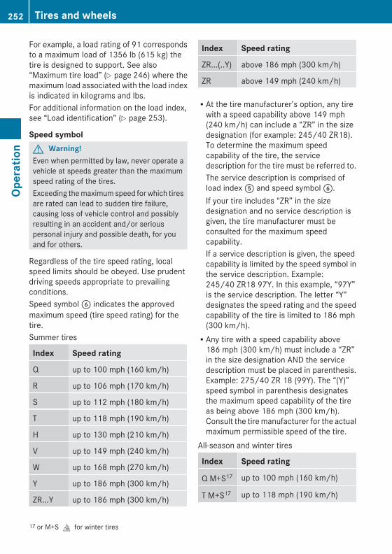
For example, a load rating of 91 correspondsto a maximum load of 1356 lb (615 kg) thetire is designed to support. See also“Maximum tire load” (Y page 246) where themaximum load associated with the load indexis indicated in kilograms and lbs.For additional information on the load index,see “Load identification” (Y page 253).
Speed symbol G Warning!Even when permitted by law, never operate avehicle at speeds greater than the maximumspeed rating of the tires.Exceeding the maximum speed for which tiresare rated can lead to sudden tire failure,causing loss of vehicle control and possiblyresulting in an accident and/or seriouspersonal injury and possible death, for youand for others.
Regardless of the tire speed rating, localspeed limits should be obeyed. Use prudentdriving speeds appropriate to prevailingconditions.Speed symbol B indicates the approvedmaximum speed (tire speed rating) for thetire.Summer tires
Index Speed rating
Q up to 100 mph (160 km/h)
R up to 106 mph (170 km/h)
S up to 112 mph (180 km/h)
T up to 118 mph (190 km/h)
H up to 130 mph (210 km/h)
V up to 149 mph (240 km/h)
W up to 168 mph (270 km/h)
Y up to 186 mph (300 km/h)
ZR...Y up to 186 mph (300 km/h)
Index Speed rating
ZR...(..Y) above 186 mph (300 km/h)
ZR above 149 mph (240 km/h)
RAt the tire manufacturer’s option, any tirewith a speed capability above 149 mph(240 km/h) can include a “ZR” in the sizedesignation (for example: 245/40 ZR18).To determine the maximum speedcapability of the tire, the servicedescription for the tire must be referred to.The service description is comprised ofload index A and speed symbol B.If your tire includes “ZR” in the sizedesignation and no service description isgiven, the tire manufacturer must beconsulted for the maximum speedcapability.If a service description is given, the speedcapability is limited by the speed symbol inthe service description. Example:245/40 ZR18 97Y. In this example, “97Y”is the service description. The letter “Y”designates the speed rating and the speedcapability of the tire is limited to 186 mph(300 km/h).RAny tire with a speed capability above
186 mph (300 km/h) must include a “ZR”in the size designation AND the servicedescription must be placed in parenthesis.Example: 275/40 ZR 18 (99Y). The “(Y)”speed symbol in parenthesis designatesthe maximum speed capability of the tireas being above 186 mph (300 km/h).Consult the tire manufacturer for the actualmaximum permissible speed of the tire.
All-season and winter tires
Index Speed rating
Q M+S17 up to 100 mph (160 km/h)
T M+S17 up to 118 mph (190 km/h)
17 or M+Sifor winter tires
252 Tires and wheelsOp
erat
ion
X164_AKB; 5; 31, en-USd2ureepe, Version: 2.11.8.1
2009-09-11T12:30:16+02:00 - Seite 252
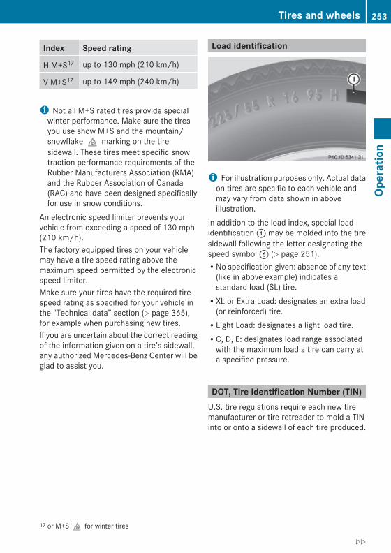
Index Speed rating
H M+S17 up to 130 mph (210 km/h)
V M+S17 up to 149 mph (240 km/h)
i Not all M+S rated tires provide specialwinter performance. Make sure the tiresyou use show M+S and the mountain/snowflakeimarking on the tiresidewall. These tires meet specific snowtraction performance requirements of theRubber Manufacturers Association (RMA)and the Rubber Association of Canada(RAC) and have been designed specificallyfor use in snow conditions.
An electronic speed limiter prevents yourvehicle from exceeding a speed of 130 mph(210 km/h).The factory equipped tires on your vehiclemay have a tire speed rating above themaximum speed permitted by the electronicspeed limiter.Make sure your tires have the required tirespeed rating as specified for your vehicle inthe “Technical data” section (Y page 365),for example when purchasing new tires.If you are uncertain about the correct readingof the information given on a tire’s sidewall,any authorized Mercedes-Benz Center will beglad to assist you.
Load identification
i For illustration purposes only. Actual dataon tires are specific to each vehicle andmay vary from data shown in aboveillustration.
In addition to the load index, special loadidentification : may be molded into the tiresidewall following the letter designating thespeed symbol B (Y page 251).RNo specification given: absence of any text
(like in above example) indicates astandard load (SL) tire.RXL or Extra Load: designates an extra load
(or reinforced) tire.RLight Load: designates a light load tire.RC, D, E: designates load range associated
with the maximum load a tire can carry ata specified pressure.
DOT, Tire Identification Number (TIN)U.S. tire regulations require each new tiremanufacturer or tire retreader to mold a TINinto or onto a sidewall of each tire produced.
17 or M+Sifor winter tires
Tires and wheels 253
Oper
atio
n
X164_AKB; 5; 31, en-USd2ureepe, Version: 2.11.8.1
2009-09-11T12:30:16+02:00 - Seite 253
Z

The TIN is a unique identifier. The TINfacilitates efforts by tire manufactures tonotify purchasers in recall situations or othersafety matters concerning tires. It givespurchasers the means to easily identify suchtires.The TIN is comprised of “Manufacturer’sidentification mark” ;, “Tire size” =, “Tiretype code” ? and “Date of manufacture”A.
i For illustration purposes only. Actual dataon tires are specific to each vehicle andmay vary from data shown in aboveillustration.
DOT (Department of Transportation)Tire branding symbol : denotes that the tiremeets requirements of the U.S. Departmentof Transportation.
Manufacturer’s identification markManufacturer’s identification mark ;denotes the tire manufacturer.New tires have a mark with two symbols.Retreaded tires have a mark with foursymbols. For more information on retreadedtires, see (Y page 233).
Tire sizeCode = indicates the tire size.
Tire type codeTire type code ? may, at the option of themanufacturer, be used as a descriptive codefor identifying significant characteristics ofthe tire.
Date of manufactureThe date of manufacture A identifies theweek and year of manufacture.The first two figures identify the week,starting with “01” to represent the first fullweek of the calendar year. The second twofigures represent the year.For example, “3208” represents the 32ndweek of 2008.
Tire ply material
i For illustration purposes only. Actual dataon tires are specific to each vehicle andmay vary from data shown in aboveillustration.
This marking tells you about the type of cordand number of plies in the sidewall : andunder the tread ;.
Tire and loading terminology
Accessory weight The combined weight (in excess of thosestandard items which may be replaced) ofautomatic transmission, power steering,power brakes, power windows, power seats,
254 Tires and wheelsOp
erat
ion
X164_AKB; 5; 31, en-USd2ureepe, Version: 2.11.8.1
2009-09-11T12:30:16+02:00 - Seite 254

radio, and heater, to the extent that theseitems are available as factory-installedequipment (whether installed or not).
Air pressure The amount of air inside the tire pressingoutward on each square inch of the tire. Airpressure is expressed in pounds per squareinch (psi), kilopascal (kPa), or bar.
Aspect ratio Dimensional relationship between tiresection height and section width expressedin percentage.
Bar Metric unit for air pressure. There are14.5038 pounds per square inch (psi) to1 bar; there are 100 kilopascals (kPa) to 1 bar.
Bead The tire bead contains steel wires wrapped bysteel cords that hold the tire onto the rim.
Cold tire inflation pressure Tire inflation pressure when your vehicle hasbeen sitting for at least 3 hours or driven nomore than 1 mile (1.6 km).
Curb weight The weight of a motor vehicle with standardequipment including the maximum capacityof fuel, oil, and coolant, and, if so equipped,air conditioning and additional optionalequipment, but without passengers andcargo.
DOT (Department of Transportation) A tire branding symbol which denotes the tiremeets requirements of the U.S. Departmentof Transportation.
GAWR (Gross Axle Weight Rating) The GAWR is the maximum permissible axleweight. The gross vehicle weight on each axlemust never exceed the GAWR for the frontand rear axle indicated on the certificationlabel located on the driver’s door B-pillar.
GTW (Gross Trailer Weight) The GTW is the weight of the trailer plus theweight of all cargo, equipment, luggage etc.loaded on the trailer.
GVW (Gross Vehicle Weight) The GVW comprises the weight of the vehicleincluding fuel, tools, spare wheel, installedaccessories, passengers and cargo and, ifapplicable, trailer tongue load. The GVW mustnever exceed the GVWR indicated on thecertification label located on the driver’s doorB-pillar.
GVWR (Gross Vehicle Weight Rating) This is the maximum permissible vehicleweight of the fully loaded vehicle (weight ofthe vehicle including all options, passengers,fuel, and cargo and, if applicable, trailertongue load). It is indicated on thecertification label located on the driver’s doorB-pillar.
Kilopascal (kPa) Metric unit for air pressure. There are 6.9 kPato 1 psi; another metric unit for air pressureis bar. There are 100 kilopascals (kPa) to1 bar.
Load index Numerical code associated with themaximum load a tire can support.
Maximum load rating The maximum load in kilograms and poundsthat can be carried by the tire.
Tires and wheels 255
Oper
atio
n
X164_AKB; 5; 31, en-USd2ureepe, Version: 2.11.8.1
2009-09-11T12:30:16+02:00 - Seite 255
Z
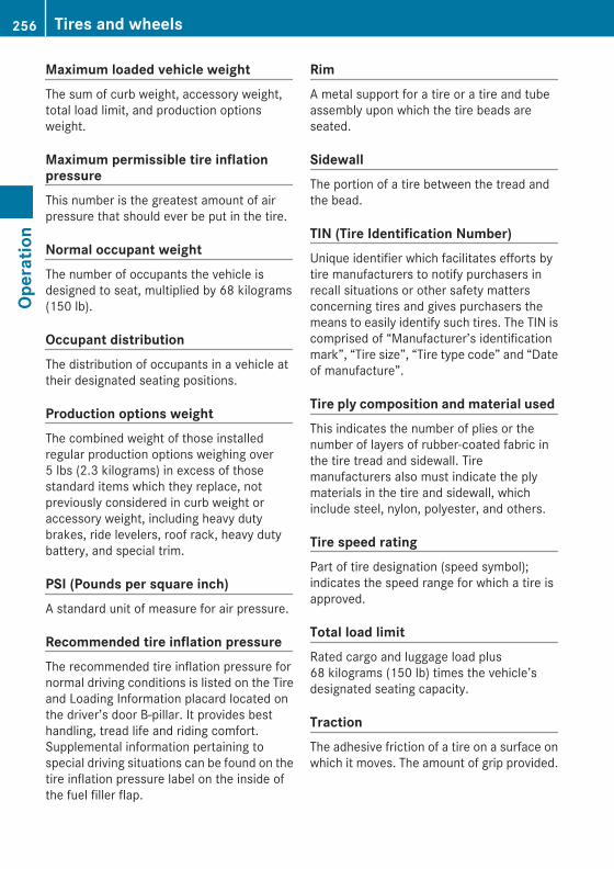
Maximum loaded vehicle weight The sum of curb weight, accessory weight,total load limit, and production optionsweight.
Maximum permissible tire inflation pressure This number is the greatest amount of airpressure that should ever be put in the tire.
Normal occupant weight The number of occupants the vehicle isdesigned to seat, multiplied by 68 kilograms(150 lb).
Occupant distribution The distribution of occupants in a vehicle attheir designated seating positions.
Production options weight The combined weight of those installedregular production options weighing over5 lbs (2.3 kilograms) in excess of thosestandard items which they replace, notpreviously considered in curb weight oraccessory weight, including heavy dutybrakes, ride levelers, roof rack, heavy dutybattery, and special trim.
PSI (Pounds per square inch) A standard unit of measure for air pressure.
Recommended tire inflation pressure The recommended tire inflation pressure fornormal driving conditions is listed on the Tireand Loading Information placard located onthe driver’s door B-pillar. It provides besthandling, tread life and riding comfort.Supplemental information pertaining tospecial driving situations can be found on thetire inflation pressure label on the inside ofthe fuel filler flap.
Rim A metal support for a tire or a tire and tubeassembly upon which the tire beads areseated.
Sidewall The portion of a tire between the tread andthe bead.
TIN (Tire Identification Number) Unique identifier which facilitates efforts bytire manufacturers to notify purchasers inrecall situations or other safety mattersconcerning tires and gives purchasers themeans to easily identify such tires. The TIN iscomprised of “Manufacturer’s identificationmark”, “Tire size”, “Tire type code” and “Dateof manufacture”.
Tire ply composition and material used This indicates the number of plies or thenumber of layers of rubber-coated fabric inthe tire tread and sidewall. Tiremanufacturers also must indicate the plymaterials in the tire and sidewall, whichinclude steel, nylon, polyester, and others.
Tire speed rating Part of tire designation (speed symbol);indicates the speed range for which a tire isapproved.
Total load limit Rated cargo and luggage load plus68 kilograms (150 lb) times the vehicle’sdesignated seating capacity.
Traction The adhesive friction of a tire on a surface onwhich it moves. The amount of grip provided.
256 Tires and wheelsOp
erat
ion
X164_AKB; 5; 31, en-USd2ureepe, Version: 2.11.8.1
2009-09-11T12:30:16+02:00 - Seite 256

Tread The portion of a tire that comes into contactwith the road.
Treadwear indicators Narrow bands, sometimes called “wear bars”that show across the tread of a tire when only1/16 in (1.6 mm) of tread remains.
TWR (Tongue Weight Rating) Maximum permissible weight on trailertongue.
Uniform Tire Quality Grading Standards A tire information system that providesconsumers with ratings for a tire’s traction,temperature and treadwear. Ratings aredetermined by tire manufacturers using U.S.government testing procedures. The ratingsare molded into the sidewall of the tire.
Vehicle maximum load on the tire Load on an individual tire that is determinedby distributing to each axle its share of themaximum loaded vehicle weight and dividingit by two.
Winter driving
General informationHave your vehicle winterized at an authorizedMercedes-Benz Center.
i Vehicles with diesel engine:Do not cover the radiator, for example witha winter front. Otherwise the readings ofthe on-board diagnostic system may beinaccurate. Some of theses readings arerequired by law and must be accurate at alltimes.
Winter tires
G Warning!Winter tires with a tread depth of less than1/6 in (4 mm) must be replaced. They are nolonger suitable for winter operation.
G Warning!If you use your spare wheel when winter tiresare fitted on the other wheels, be aware thatthe difference in tire characteristics may verywell impair turning stability and that overalldriving stability may be reduced. Adapt yourdriving style accordingly.Have the spare wheel replaced by a regularroad wheel with a winter tire at the nearestauthorized Mercedes-Benz Center.
Always use winter tires at temperaturesbelow 45‡ (7†) and whenever wintry roadconditions prevail. Not all M+S rated tiresprovide special winter performance. Makesure the tires you use show the mountain/snowflakeimarking on the tire sidewall.These tires meet specific snow tractionperformance requirements of the RubberManufacturers Association (RMA) and theRubber Association of Canada (RAC) andhave been designed specifically for use insnow conditions. Use of winter tires is theonly way to achieve the maximumeffectiveness of your vehicle’s driving safetysystems such as the ABS and the ESP® inwinter operation.For safe handling, make sure all mountedwinter tires are of the same make and havethe same tread design.For information on winter tires for yourvehicle model, see the “Technical data”section (Y page 365).Always observe the speed rating of the wintertires installed on your vehicle.
Winter driving 257
Oper
atio
n
X164_AKB; 5; 31, en-USd2ureepe, Version: 2.11.8.1
2009-09-11T12:30:16+02:00 - Seite 257
Z

After installing winter tires:X Check the tire inflation pressure and adjust
it if necessary (Y page 237).X Restart the tire pressure loss warning
system (Y page 237) or the Advanced TirePressure Monitoring System (Y page 239).
Snow chains! Vehicles with Adaptive Damping System
(ADS):When driving with snow chains, do notselect SPORT mode as this may result indamage to your vehicle.
! Some tire sizes do not leave adequateclearance for snow chains. To help avoidserious damage to your vehicle or tires,make sure the use of snow chains ispermissible as specified in the “Technicaldata” section of this Operator’s Manual.
Snow chains should only be driven on snow-covered roads at speeds not to exceed30 mph (50 km/h). Remove chains as soonas possible when driving on roads withoutsnow.Observe the following guidelines when usingsnow chains:RUse of snow chains is not permissible with
all wheel/tire combinations (Y page 365).RUse snow chains in pairs and on rear
wheels only. Follow the manufacturer’smounting instructions.
! If snow chains are mounted to the frontwheels, they may scrape against the bodyor axle components. The tires or the vehiclecould be damaged as a result.ROnly use snow chains that are approved by
Mercedes-Benz. Any authorized Mercedes-Benz Center will be glad to advise you onthis subject.RUse of snow chains may be prohibited
depending on location. Always check local
and state laws before installing snowchains.RDo not use snow chains on the spare wheel.
i When driving with snow chains, you maywish to switch off the ESP® (Y page 63)before setting the vehicle in motion. Thiswill improve the vehicle’s traction.
Winter driving instructions
G Warning!If the vehicle becomes stuck in snow, makesure snow is kept clear of the exhaust pipeand from around the vehicle with the enginerunning. Otherwise, deadly carbon monoxide(CO) gases may enter vehicle interiorresulting in unconsciousness and death.To assure sufficient fresh air ventilation, opena window slightly on the side of the vehiclenot facing the wind.
G Warning!The outside temperature indicator is notdesigned to serve as an ice-warning deviceand is therefore unsuitable for that purpose.Indicated temperatures just above thefreezing point do not guarantee that the roadsurface is free of ice. The road may still be icy,especially in wooded areas or on bridges.
G Warning!On slippery road surfaces, never downshift inorder to obtain braking action. This couldresult in drive wheel slip and reduced vehiclecontrol. Your vehicle’s ABS will not preventthis type of control loss.Do not engage the transfer case in positionLOW when driving on ice or packed snow. Atspeeds below 18 mph (30 km/h) vehiclesteering is adversely affected by the Off-roadABS.
The most important rule for slippery or icyroads is to drive sensibly and to avoid abruptacceleration, braking and steering
258 Winter drivingOp
erat
ion
X164_AKB; 5; 31, en-USd2ureepe, Version: 2.11.8.1
2009-09-11T12:30:16+02:00 - Seite 258

maneuvers. Do not use the cruise controlsystem under such conditions.When the vehicle is in danger of skidding, shiftthe automatic transmission to neutralposition N. Try to keep the vehicle undercontrol by corrective steering action.
i For information on driving with snowchains, see “Snow chains” (Y page 258).
Road salts and chemicals can adverselyaffect braking efficiency. Increased pedalforce may become necessary to produce thenormal brake effect.Depressing the brake pedal periodically whentraveling at length on salt-strewn roads canbring road-salt-impaired braking efficiencyback to normal.If the vehicle is parked after being driven onsalt-treated roads, the braking efficiencyshould be tested as soon as possible afterdriving is resumed.
G Warning!Make sure not to endanger any other roadusers when carrying out these brakingmaneuvers.
Driving instructions
Drive sensibly – save fuelTo save fuel you should:RKeep tires at the recommended inflation
pressures.RRemove unnecessary loads.RRemove carriers when not in use.RRemove the crossbars when not in use.RAllow engine to warm up under low load
use.RAvoid frequent acceleration and
deceleration.RHave all maintenance work performed at
the intervals specified in the MaintenanceBooklet and as required by the
Maintenance system. Contact anauthorized Mercedes-Benz Center.
Fuel consumption is also increased by drivingin cold weather, in stop-and-go traffic, onshort trips and in mountainous areas.
Drinking and driving
G Warning!Drinking and driving and/or taking drugs anddriving are very dangerous combinations.Even a small amount of alcohol or drugs canaffect your reflexes, perceptions andjudgment.The possibility of a serious or even fatalaccident are greatly increased when you drinkor take drugs and drive.Do not drink or take drugs and drive or allowanyone to drive who has been drinking ortaking drugs.
Pedals
G Warning!Make sure absolutely no objects areobstructing the pedals’ range of movement.Keep the driver’s footwell clear of allobstacles. If there are any floormats orcarpets in the footwell, make sure that thepedals still have sufficient clearance.During sudden driving or braking maneuvers,the objects could get caught between thepedals. You could then no longer brake oraccelerate. This could lead to accidents andinjury.
Power assistance
G Warning!There is no power assistance for the steeringand the brake when the engine is not running.
Driving instructions 259
Oper
atio
n
X164_AKB; 5; 31, en-USd2ureepe, Version: 2.11.8.1
2009-09-11T12:30:16+02:00 - Seite 259
Z

Steering and braking requires significantlymore effort and you could lose control of thevehicle and cause an accident as a result.Do not turn off the engine while the vehicle isin motion.
Brakes
Downhill grades! When driving down long and steep
grades, relieve the load on the brakes byshifting into a lower gear to use theengine’s braking power. This helps preventoverheating of the brakes and reduceswear.When using the engine’s braking power, adrive wheel may not spin for an extendedperiod of time, e.g. on slippery roadsurfaces. This may cause serious damageto the drivetrain which is not covered by theMercedes-Benz Limited Warranty.
Continuous or hard braking
G Warning!Resting your foot on the brake pedal willcause excessive and premature wear of thebrake pads.It can also result in the brakes overheating,thereby significantly reducing theireffectiveness. It may not be possible to stopthe vehicle in sufficient time to avoid anaccident.
After hard braking, it is advisable to drive onfor some time, rather than immediately park,so that the air stream will cool down thebrakes faster.
Wet roads
G Warning!After driving in heavy rain for some timewithout applying the brakes or through waterdeep enough to wet brake components, the
first braking action may be somewhatreduced and increased pedal pressure may benecessary to obtain expected brake effect.Maintain a safe distance from vehicles infront.
To help prevent brake disk corrosion afterdriving on wet or salt-covered roads, it isadvisable to brake the vehicle withconsiderable force prior to parking. The heatgenerated serves to dry the brakes.
Salt-covered roads
G Warning!A layer of salt on the brake discs and the brakelinings may cause a delay in the brakingeffect, resulting in a significantly increasedbraking distance, which could lead to anaccident.To avoid this danger, you should:Roccasionally brake carefully when you are
driving on salt-covered roads, so that anylayer of salt that may have built up on thebrake discs and the brake linings isremoved without putting other road usersat riskRmaintain a greater distance to the vehicle
ahead and drive with particular careRcarefully apply the brakes at the end of a
trip and immediately after commencing anew trip, so that salt residues are removedfrom the brake disc
Brake service! The brake fluid level in the reservoir may
be too low if the brake warning lamp in theinstrument cluster comes on and anacoustic warning sounds although theparking brake is released. Observeadditional messages in the multifunctiondisplay that may appear.Brake pad wear or a leak in the system maybe the reason for low brake fluid in thereservoir.
260 Driving instructionsOp
erat
ion
X164_AKB; 5; 31, en-USd2ureepe, Version: 2.11.8.1
2009-09-11T12:30:16+02:00 - Seite 260

Have the brake system inspectedimmediately. Contact an authorizedMercedes-Benz Center.
All checks and service work on the brakesystem should be carried out by qualifiedtechnicians only. Contact an authorizedMercedes-Benz Center.Only install brake pads and use brake fluidrecommended by Mercedes-Benz.
G Warning!If other than recommended brake pads areinstalled, or other than recommended brakefluid is used, the braking properties of thevehicle can be degraded to an extent that safebraking is substantially impaired. This couldresult in an accident.
! Only conduct operational or performancetests on a two-axle dynamometer. If suchtests are necessary, contact an authorizedMercedes-Benz Center. You couldotherwise seriously damage the brakesystem or the transfer case which is notcovered by the Mercedes-Benz LimitedWarranty.
! Because the ESP® operatesautomatically, the engine and ignition mustbe shut off (SmartKey in starter switchposition 0 or 1 or KEYLESS-GO start/stopbutton in position 0 or 1) when the parkingbrake is being tested on a brake testdynamometer. Such testing should be nolonger than 10 seconds.Active braking action through the ESP®
may otherwise seriously damage the brakesystem which is not covered by theMercedes-Benz Limited Warranty.
If your brake system is only subjected tomoderate loads, you should occasionally testthe effectiveness of the brakes by applyingabove-normal braking pressure at higherspeeds. This will also enhance the grip of thebrake pads.
G Warning!Make sure not to endanger any other roadusers when carrying out these brakingmaneuvers.
Refer to the description of the Brake AssistSystem (BAS) (Y page 63).
Parking brake When driving on wet roads or dirt coveredsurfaces, road salt and/or dirt can get intothe parking brake.To prevent corrosion and a reduction in thebraking power of the parking brake, observethe following:X From time to time, lightly engage the
parking brake before driving off.X Drive a distance of approximately 110 yds
(100 m) at a maximum speed of 12 mph(20 km/h).
G Warning!While performing this procedure pleaseassure that the vehicle is stopped beforeapplying the parking brake. Otherwise therear wheels could lock up. You could losecontrol of the vehicle and cause an accident.In addition, the vehicle’s brake lights do notlight up when the parking brake is engaged.Make sure not to endanger any other roadusers when you engage the parking brake.
Driving offWarm up the engine smoothly. Do not placefull load on the engine until the operatingtemperature has been reached.
! When driving off on a slippery surface, donot allow a drive wheel to spin for anextended period with the ESP® switchedoff. Doing so may cause serious damage tothe drivetrain which is not covered by theMercedes-Benz Limited Warranty.
Driving instructions 261
Oper
atio
n
X164_AKB; 5; 31, en-USd2ureepe, Version: 2.11.8.1
2009-09-11T12:30:16+02:00 - Seite 261
Z

! Simultaneously depressing theaccelerator pedal and applying the brakesreduces engine performance and causespremature brake and drivetrain wear whichis not covered by the Mercedes-BenzLimited Warranty.
HydroplaningDepending on the depth of the water layer onthe road, hydroplaning may occur, even at lowspeeds and with new tires. In heavy rain orwhen conditions indicate possiblehydroplaning:X Reduce vehicle speed.X Avoid track grooves in the road.X Apply brakes cautiously.
Standing water! Do not drive through flooded areas.
Before driving through water, determine itsdepth.If you must drive through standing water,drive slowly to prevent water from enteringthe passenger compartment or the enginecompartment. Water in these areas couldcause damage to electrical components orwiring of the engine or transmission, orcould result in water being ingested by theengine through the air intake causingsevere internal engine damage. Any suchdamage is not covered by the Mercedes-Benz Limited Warranty.
i Select the raised level (Y page 159)before driving through standing water.
For more information, see “Driving throughwater” (Y page 266).
Off-road driving
G Warning!Do not load items on the crossbars. It maycause instability during some maneuverswhich could result in an accident.Drive slowly in unknown terrain. This willmake it easier to recognize unexpectedobstacles and avoid damage to the vehicle.To help avoid the vehicle rolling over, neverturn it around on steep inclines. If the vehiclecannot complete the attempted climb, back itdown in reverse gear.Do not drive along the side of a slope. Thevehicle might otherwise rollover. If in doing sothe vehicle begins to show a tendency to roll,immediately steer into a line of gravity(straight up or downhill).Never let the vehicle roll backwards in idle.You may lose control of the vehicle if you useonly the service brake. For information ondriving downhill, see “Driving downhill”.
G Warning!Sand, dirt, mud and other material havingfriction property can cause exceptional wearand tear as well as brake failure.Have the brakes checked for dirt build-up andcleaned. There is otherwise a risk that fullbraking power may not be available in anemergency.
G Warning!Please be aware that by raising the vehiclelevel, the center of gravity also rises.Therefore, always ensure that the vehiclelevel is as low as possible. With higher rideheight the ESP® may activate earlier in certainsituations.
Read this chapter carefully before you beginoff-road travel.Familiarize yourself with the vehiclecharacteristics and gear changing before youattempt any difficult terrain off-road driving.
262 Driving instructionsOp
erat
ion
X164_AKB; 5; 31, en-USd2ureepe, Version: 2.11.8.1
2009-09-11T12:30:16+02:00 - Seite 262

We recommend that you start out with easyoff-road travel.
Special driving features for off-road drivingThe following driving features are available forspecific kind of operation:ROff-road ABS (Y page 63)ROff-road ESP® (Y page 65)ROff-road 4-ETS (Y page 64)RHill-start assist system (Y page 117)RLOW RANGE mode (Y page 120)RDifferential locks (Y page 121)RDownhill Speed Regulation (DSR)
(Y page 155)ROff-road driving program (Vehicles without
enhanced off-road package) (Y page 158)RAir suspension program (Y page 159)
Off-road driving rulesREngage the off-road driving program
(Y page 158) or LOW RANGE mode(Y page 120) before driving under off-roadconditions.RIf necessary, activate differential locks
(Y page 121).RMake sure you select a vehicle level
(Y page 159) appropriate to thetopographical conditions. Always makesure the vehicle has enough groundclearance.RFasten items being carried as securely as
possible (Y page 194).RAlways navigate gradients with the engine
on and with the transmission engaged in agear. Switch on the DSR (Y page 155) tohelp maintain a preset speed.
! Observe the following during off-roaddriving:RKeep doors, tailgate, windows, and tilt/
sliding sunroof closed whenever drivingoff-road.RAdjust vehicle speed to condition of
terrain. The more uneven, rutty andsteeper the terrain, the lower the speedshould be. Drive through water slowly atan even speed, avoiding a bow wave.RBe especially careful when driving in
unknown territory. It may be necessaryto get out of the vehicle and scout thepath you intend to take.RWatch out for obstacles, such as rocks,
holes, tree stumps and ruts.RBefore driving through water, determine
its depth.RDo not stop vehicle while immersed in
water, and do not shut off the engine.RIn sandy soil, drive at a steady speed as
allowed by conditions. This helpsovercome the vehicle rolling resistanceand reduces the likelihood of the vehiclesinking into the ground.RDo not initiate jumps with the vehicle. It
interrupts the forward momentum of thevehicle.RAlways drive onto slopes with the engine
running and the vehicle in gear.RDo not shift automatic transmission into
neutral position N.
G Warning!Do not reduce the tire inflation pressurebefore driving through sand. However, if youdo so, remember to correct the tire inflationpressure before continuing your trip. Drivingwith reduced tire inflation pressure increasesthe risk of losing control of the vehicle androlling over.
Driving instructions 263
Oper
atio
n
X164_AKB; 5; 31, en-USd2ureepe, Version: 2.11.8.1
2009-09-11T12:30:16+02:00 - Seite 263
Z

Checklist before off-road driving
Engine oil levelRCheck the engine oil level (Y page 230).
Only with a proper oil level can the vehicleobtain a trouble-free oil supply, even onsteep gradients.
! If the engine oil level warning lamp comeson while driving, stop the vehicle in a safelocation or as soon at is safe to do so.Check the engine oil level.The engine oil level warnings should not beignored. Extended driving with the symboldisplayed could result in serious enginedamage that is not covered by theMercedes-Benz Limited Warranty.
TiresRCheck the tread depth and maintain
specified tire inflation pressure. A placardwith the recommended tire inflationpressures is located on the driver’s door B-pillar (Y page 243).RCheck tires for possible damage and
remove foreign objects.RReplace missing valve caps.
RimsRDented or bent rims can cause tire inflation
pressure loss and damage the tire beads.For this reason, check and, if necessary,change rims before driving off-road.
Vehicle tool kitRCheck if the jack (Y page 286) is
functional.RAlways take the vehicle tool kit, a strong
tow rope, a shovel and a small plank (to putunder the jack on sandy soil) with you.
Driving in steep terrain
Slope angle: Overhang angle, front; Overhang angle, rear
Vehicleswith airsuspensionprogram
:
GL 450,GL 350BlueTEC
:
GL550
;
allmodels
Raised level 31° 32° 26°
Highway 26° 27° 21°
Vehicleswithenhancedoff-roadpackage
:
GL 450,GL 350BlueTEC
:
GL550
;
allmodels
Off-roadlevel 3
32° 33° 27°
Off-roadlevel 2
31° 32° 26°
Off-roadlevel 1
28° 28° 23°
Highway 26° 27° 21°
RComply with the warnings (Y page 262) andrules for off-road driving (Y page 263).RDriving on embankments, slopes and other
steep inclines should only be done straightup or downhill, i.e. in the line of gravity.Maximum vehicle climbing ability is a
264 Driving instructionsOp
erat
ion
X164_AKB; 5; 31, en-USd2ureepe, Version: 2.11.8.1
2009-09-11T12:30:16+02:00 - Seite 264

100% grade which is equivalent to a slopeangle of 45°. Keep in mind that theclimbing ability of the vehicle depends onterrain conditions.RShift automatic transmission into gear
range 1 (Y page 118).RDrive slowly.RAvoid excessive engine speeds – drive with
moderate engine speeds (max. 3 000 rpm).RUtilize the engine’s braking power when
descending a slope, observe the enginespeed (do not overrev the engine). Applythe service brake as needed.
i For maximum engine speed, see“Tachometer” (Y page 125) and see vehiclespecification for your vehicle(Y page 362).RCheck the brakes after a lengthy
downgrade drive.
G Warning!Never turn the vehicle around on steepinclines. The vehicle might roll over. If thevehicle cannot complete the attempted climb,back it down in reverse gear.
i The hill-start assist system supports youwhen driving uphill.For more information, see “Hill-start assistsystem” (Y page 155).
Traction in steep terrainThe maximum vehicle climbing ability is a100% grade which is equivalent to a slopeangle of 45°. Keep in mind that the climbingability of the vehicle depends on terrainconditions.Be easy on the accelerator and watch forcontinuous wheel traction when driving insteep terrain.
i The 4-ETS helps greatly when starting outon a steep incline when the front wheelshave then the tendency to slip due to theweight shifting towards the rear axle.
The 4-ETS recognizes the situation andlimits the torque for the front wheels bybraking them.Simultaneously the torque for the rearwheels is increased.
i Vehicles with enhanced off-road packageare equipped with automatic locks for thecenter and rear axle differential to improvevehicle traction.
Driving across a hilltopDecelerate just ahead of a hilltop (do not shiftautomatic transmission into neutral positionN), to prevent the vehicle from speeding uptoo much after climbing a hill.Use the momentum of the vehicle to driveacross the hilltop.After climbing a hill, driving in this mannerprevents the vehicle from:Rlosing ground contact when cresting hillsRlosing its forward momentumRspeeding up too much after climbing the hill
Driving downhillRDrive slowly.RDo not drive at an angle to the incline. Steer
into the line of gravity and drive with thefront wheels pointing straight downhill.Otherwise, the vehicle may slide sidewaysoff the path and roll over.RShift automatic transmission into gear
range 1 (Y page 118).ROn steep inclines, use the Downhill Speed
Regulation (Y page 155).RUtilize the engine’s braking power to
reduce vehicle speed.If this is insufficient, apply the brakesgently. Make sure the vehicle is moving inthe line of gravity.RCheck the brakes after a lengthy
downgrade drive.
Driving instructions 265
Oper
atio
n
X164_AKB; 5; 31, en-USd2ureepe, Version: 2.11.8.1
2009-09-11T12:30:16+02:00 - Seite 265
Z

i The special Off-road ABS (Y page 63)setting allows for precise and brief(cyclical) blocking of the front wheels,permitting them to dig into loose ground.Remember that, when stopped, the frontwheels slide across a surface and thus losetheir ability to steer the vehicle.
Driving through water
: Fording depth
Vehicles with airsuspensionprogram (raisedlevel)
:
20 in (50 cm)
Vehicles withenhanced off-roadpackage
:
Off-road level 1 20 in (50 cm)
Off-road level 2 20 in (50 cm)
Off-road level 3 23.6 in (60 cm)
RBefore driving through water, determine itsdepth.
! The water depth must not exceed therespective value listed in the table. Theground under the water might not be firmwhich could result the water being deeperthan expected when driving the vehicle
through it. Please note that the water levelis correspondingly lower for flowing water.RSelect the highest vehicle level possible
(Y page 159).RSwitch to off-road driving program
(Y page 158) or LOW RANGE mode(Y page 120) before driving through water.RShift automatic transmission into gear
range 1 or 2 (Y page 118).RAvoid high engine speeds.REnter and leave the water only at a shallow
spot, driving at walking speed.
! Never accelerate before driving into thewater. The bow wave could force water intothe engine and auxiliary equipment, thusdamaging them.RDrive through the water slowly and at a
constant speed.RDo not stop vehicle while immersed in
water, and do not shut off the engine.
! Do not open any of the vehicle’s doorswhile driving through water. Water couldotherwise enter the vehicle interior anddamage the vehicle’s electronics, as well asthe interior equipment.RThere is a very high level of driving
resistance in water. The surface is slipperyand may not be firm, making pulling awayin water difficult and dangerous.RMake sure that only small bow waves are
formed when driving the vehicle throughwater.RClean mud off the tire tread after driving
through water.RTo dry the brakes, apply pressure to the
brake pedal several times while drivingafter leaving the water.
266 Driving instructionsOp
erat
ion
X164_AKB; 5; 31, en-USd2ureepe, Version: 2.11.8.1
2009-09-11T12:30:16+02:00 - Seite 266

Crossing obstacles
! Obstacles can damage the vehicleunderbody or suspension components. Ifpossible use the assistance of a secondperson outside the vehicle to scout thepath you intend to take and check foradequate ground clearance when you crossobstacles with your vehicle. The personassisting you outside the vehicle shouldalways be a safe distance away from thevehicle and positioned so that he or shecannot get hurt in case of any unexpectedvehicle movement.After off-road driving or crossing obstacles,inspect vehicle for any damage, especiallyvehicle underbody and suspensioncomponents. Failure to do so can adverselyaffect the vehicle’s future performance,including increased chance of an accident.
When driving over tree stumps, big rocks andother obstacles, observe the following rules:RMake sure the off-road driving program
(Y page 158) or if equipped theLOW RANGE mode (Y page 120) isswitched on.RAvoid high engine speeds.RShift automatic transmission into gear
range 1 (Y page 118).RCheck the vehicle clearance before
crossing obstacles.RCross obstacles (e.g. tree stumps or big
rocks) very slowly by aiming one of the front
wheels at the center of the obstacle, andrepeat same with the rear wheel.
! Special attention is needed when youcross obstacles on a steep incline.The vehicle could slide sideways as a resultof its possible slanted position which in turnmay result in the vehicle tipping or rollingover.
Driving on sand
G Warning!Do not reduce the tire inflation pressurebefore driving through sand. However, if youdo so, remember to correct the tire inflationpressure before continuing your trip. Drivingwith reduced tire inflation pressure increasesthe risk of losing control of the vehicle androlling over.
When driving on sand, observe the followingrules:RSet the raised level (Y page 159).RAvoid high engine speeds.RShift automatic transmission into a gear
range that is appropriate for the terrain.RIn sandy soil, drive at a steady speed as
conditions permit. This helps overcome thevehicle rolling resistance and reduce thelikelihood of the vehicle sinking into theground.RDrive in tracks of other vehicles if they are
not too deep and you have sufficientclearance.
Ruts A number of off-road tracks or other bywayshave deep ruts which can cause theunderbody to come in contact with theground.RMake sure the off-road driving program
(Y page 158) or, if equipped, the
Driving instructions 267
Oper
atio
n
X164_AKB; 5; 31, en-USd2ureepe, Version: 2.11.8.1
2009-09-11T12:30:16+02:00 - Seite 267
Z

LOW RANGE mode (Y page 120) isswitched on.RSet the raised level (Y page 159).
! Check that the ruts are not too deep andyour vehicle’s clearance is sufficient.Otherwise:Ryour vehicle may be damagedRthe underbody of the vehicle may come
in contact with the ground and you mayget stuck
RAvoid high engine speeds.RShift automatic transmission into gear
range 1 (Y page 118).RDrive next to the ruts rather than through
them if at all possible.RIf the ruts are too deep to drive in, drive with
one side of the vehicle on the grassy centerstrip if the route permits.
Returning from off-road driving
G Warning!If you feel a sudden significant vibration orride disturbance, or you suspect that possibledamage to your vehicle has occurred, youshould turn on the hazard warning flashers,carefully slow down, and drive with caution toan area which is a safe distance from the road.Inspect the tires and the vehicle underbodyfor possible damage. If the vehicle or tiresappear unsafe, have the vehicle towed to thenearest authorized Mercedes-Benz Center ortire dealer for repairs.
Off-road driving increases strain on thevehicle.We recommend that you inspect the vehiclefor possible damage after each off-road trip.Recognizing any damage and a subsequenttimely repair reduces the chance of a possiblebreakdown or accident later on.
Proceed as follows:RSwitch off the off-road driving program
(Y page 158) or the LOW RANGE mode(Y page 120).RSwitch off the DSR (Y page 156).RSet the differential locks to AUTO
(Y page 122).RLower the vehicle back to a level suitable
for road conditions, e.g. highway/high-speed level (Y page 159).RClean all exterior lamps and check for
possible damage.RClean the front and rear license plate.RRemove excessive dirt from tires, wheels,
wheel housings, and underbody.For instance, after driving in mud, clean theradiator, chassis, engine, brakes, andwheels from extreme dirt using a strong jetof water.RCheck tires for possible damage.RInspect vehicle underbody, oil pan, brake
hoses, etc., as well as vehicle underbodyfor possible damage.RCheck for brush or branches caught in the
underbody.
! Brush or branches could increase thepossibility of a fire, as well as cut fuel and/or brake lines, puncture rubber bellows ofthe axles or drive shafts.RAfter continued operation in mud, sand,
water or other dirty conditions clean thebrake discs, wheels, brake pads and checkand clean axle joints.RConduct a brake test.
268 Driving instructionsOp
erat
ion
X164_AKB; 5; 31, en-USd2ureepe, Version: 2.11.8.1
2009-09-11T12:30:16+02:00 - Seite 268

Trailer towing
G Warning!Failure to use proper equipment and drivingtechnique can result in a loss of vehiclecontrol when towing a trailer.Improper towing or failure to follow theinstructions in this manual can result invehicle damage and/or serious personalinjury. Follow the guidelines below carefullyto assure safe trailer operation.Contact an authorized Mercedes-Benz Centershould you require an explanation ofinformation contained in this manual.
Trailer hitch ROnly install a trailer hitch receiver approved
for your vehicle.For information on availability andinstallation, contact an authorizedMercedes-Benz Center.RThe bumpers on your vehicle are not
designed for use with clamp-type hitches.Do not attach rental hitches or otherbumper-type hitches to them.RTo reduce the possibility of damage,
remove the hitch ball adapter from thereceiver when not in use.
Electrical connections The vehicle is prewired to accept the seven-wire harness included in the Mercedes-Benzapproved trailer hitch receiver kit.
i A four-pole conversion plug is availablefrom your authorized Mercedes-BenzCenter as a spare part.
For further information, contact anauthorized Mercedes-Benz Center.
Vehicle and trailer weights and ratings The Gross Trailer Weight (GTW) is the weightof the trailer plus the weight of all cargo,equipment, luggage, etc. loaded on the
trailer. The maximum permissible GTW to betowed: 7 500 lb (3 402 kg).Trailer Tongue Weight Rating (TWR) is themaximum permissible weight on the trailertongue: 600 lb (272 kg) limit for Mercedes-Benz approved hitch receiver.
Loading a trailerRWhen loading a trailer, you should observe
that neither the permissible GTW, nor theGross Vehicle Weight Rating (GVWR) areexceeded. The GVWR is indicated on thecertification label located on the driver’sdoor B-pillar (Y page 242).Maximum permissible values are listed onthe safety compliance certification labelsfor the vehicle and for the trailer to betowed.The lowest value listed must be selectedwhen determining how the vehicle andtrailer are loaded.RThe tongue weight at the hitch ball must be
added to the rear axle weight to preventexceeding the rear Gross Axle WeightRating (GAWR). The GAWR is indicated onthe certification label located on thedriver’s door B-pillar (Y page 242).
i Mercedes-Benz recommends loading thetrailer in such a manner that it has a tongueweight between 8 % and 15 % of the GTW.
i The weight of other accessories,passengers and cargo will reduce themaximum trailer weight and tongue weightyour vehicle can tow.
Checking weights of vehicle and trailerRTo assure that the towing vehicle and trailer
are in compliance with the maximumpermissible weight limits, have the loadedrig (towing vehicle including driver,passengers and cargo, trailer fully loaded)weighed on a commercial scale.RCheck the vehicle’s front and rear gross
axle weight, the Gross Trailer Weight (GTW)and tongue weight.
Driving instructions 269
Oper
atio
n
X164_AKB; 5; 31, en-USd2ureepe, Version: 2.11.8.1
2009-09-11T12:30:16+02:00 - Seite 269
Z

The values as measured must not exceedthe weight limits listed under “Vehicle andtrailer weights and ratings” (Y page 269).
Coupling a trailer
G Warning!While you are coupling or decoupling a trailer,make sure nobody locks or unlocks thevehicle and/or opens or closes doors or thetailgate.The vehicle’s level could change and youcould endanger yourself and/or others as aresult.Make sure that you do not operate the ADSbutton or the vehicle level control systemwhen coupling/decoupling the trailer.
Observe maximum permitted trailerdimensions (width and length).Most states and all Canadian provincesrequireRsafety chains between the towing vehicle
and the trailerThe chains should be criss-crossed underthe trailer tongue. They must be attachedto the hitch receiver, and not to thevehicle’s bumper or axle.Make sure to leave enough slack in thechains to permit turning corners.Ra separate brake system at various trailer
weightsRa break-away switch on trailers with a
separate brake system.Check with your local state laws for specificrequirements.The switch activates the trailer brakes inthe possible event that the trailer mightseparate from the tow vehicle.
! Do not connect a trailer brake system (iftrailer is so equipped) directly to thevehicle’s hydraulic brake system, as yourvehicle is equipped with antilock brakes. Ifyou do, neither the vehicle’s brakes nor thetrailer’s brakes will function properly.
i The provided vehicle electrical wiringharness for trailer towing has a brake signalwire for hook-up to a brake controller.
X Make sure the automatic transmission is inpark position P (Y page 115).
X Engage the parking brake for the vehicle(Y page 112).
X Start the engine (Y page 108).X Select the highway level (Y page 159).X Vehicles with Adaptive Damping System
(ADS):Set the ADS to AUTO or COMF(Y page 159).
X Turn off the engine (Y page 113).X Close all doors and the tailgate.X Attach the trailer.X Plug in all electrical connectors.
i When you are towing a trailer, the vehiclelevel always remains in the highway setting.The following applies additionally whentowing a trailer:RThe vehicle is lowered to the highway
level when it reaches a speed of 5 mph(8 km/h) if not set to highway level.RThe highspeed level is not available.The restrictions that apply to towing alsoapply when using accessories that areconnected to the trailer power socket, suchas a bicycle rack.
Towing a trailer There are many different laws, includingspeed limit restrictions, having to do withtrailer towing. Make sure your rig will be legal,not only for where you reside, but also forwhere you will be driving. A good source forthis information can be the police or localauthorities.Note the following, when driving with a trailer:RIn order to gain skill and an understanding
of the vehicle’s behavior, you should
270 Driving instructionsOp
erat
ion
X164_AKB; 5; 31, en-USd2ureepe, Version: 2.11.8.1
2009-09-11T12:30:16+02:00 - Seite 270

practice turning, stopping and backing upin an area which is free of traffic.RBefore you start driving check the
- trailer hitch- break-away switch- safety chains- electrical connections- lighting- tires
RAdjust the mirrors (Y page 94) to permitunobstructed view beyond rear of trailer.RIf the trailer has electric brakes, start your
vehicle and trailer moving slowly, and thenapply only the trailer brake controller byhand to make sure the brakes are workingproperly.RAlways secure items in the trailer to
prevent load shifts while driving.RWhen towing a trailer, check occasionally
to make sure the load is secure, and thattrailer lighting and brakes (if so equipped)are functioning properly.RTake into consideration that when towing a
trailer, the handling characteristics aredifferent and less stable from those whenoperating the vehicle without a trailer.It is important to avoid sudden maneuvers.RThe vehicle and trailer combination is
heavier, and therefore limited inacceleration and climbing ability, and has alarger braking distance.It is more prone to reacting to cross windgusts, and requires more sensitive steeringinput.RIf possible, do not brake abruptly, but
rather engage the brake slightly at first topermit the trailer to activate its brake. Thenincrease the braking force.
! If the trailer should begin to sway, reducethe vehicle’s speed immediately.
Do not attempt to straighten out the towvehicle and trailer by increasing the speed.RIf the transmission shifts between gears on
inclines repeatedly, shift to a lower gearrange manually (Y page 118). Select 4, 3,2 or 1.A lower gear and reduction of speedreduces the chance of engine overloadingand/or overheating.ROn very steep inclines, not manageable
with automatic transmission in gear range1, switch on off-road driving program(Y page 158) or LOW RANGE mode(Y page 120).RWhen going down an incline, shift into a
lower gear and use the engine’s brakingeffect.Avoid riding the brakes, thus overheatingthe vehicle and trailer brakes (if soequipped).RIf the engine coolant rises to an extremely
high temperature when the air conditioningis on, turn off the air conditioning system.Engine coolant heat can be additionallyvented by opening the windows, switchingthe climate control fan speed to high andsetting the temperature control to themaximum.RDuring a passing maneuver extreme care
must be exercised since your vehicle witha trailer will require additional passingdistance ahead than when driving withouta trailer.Because your vehicle and trailer is longerthan your vehicle alone, you will also needto go much farther ahead of the passedvehicle before you can return to your lane.
Decoupling a trailer
G Warning!While you are coupling or decoupling a trailer,make sure nobody locks or unlocks the
Driving instructions 271
Oper
atio
n
X164_AKB; 5; 31, en-USd2ureepe, Version: 2.11.8.1
2009-09-11T12:30:16+02:00 - Seite 271
Z

vehicle and/or opens or closes doors or thetailgate.The vehicle’s level could change and youcould endanger yourself and/or others as aresult.Make sure that you do not operate the ADSbutton or the vehicle level control systemwhen coupling/decoupling the trailer.
X Make sure the automatic transmission is inpark position P (Y page 115).
X Engage the parking brake for the vehicle(Y page 112).
X Start the engine (Y page 108).X Close all doors and the tailgate.X Engage the parking brake for the trailer.
G Warning!As soon as you disconnect the electricalconnection between the trailer and thevehicle, the vehicle will lower. To help avoidpersonal injury, make sure no one is near thewheel housing or underneath the vehiclebefore the electrical connection isdisconnected.When you decouple the trailer, the vehicle istemporarily raised because the springs arerelieved of load. Be especially careful duringthis process, as you could otherwise injureyourself and/or others. Make sure that anypersons remaining in the vehicle do not pressthe switches for vehicle level control or theADS.
X Disconnect all electrical plug connectors.X Decouple the trailer.X Make sure that the trailer coupling is free
of load.X Turn off the engine (Y page 113).
Driving abroadIf you plan to drive the vehicle outside the U.S.or Canada, you should request dealer
network information for your destination fromany authorized Mercedes-Benz Center.
Control and operation of radio transmitter
Safety notes
G Warning!Please do not forget that your primaryresponsibility is to drive the vehicle. A driver’sattention to the road must always be his/herprimary focus when driving. For your safetyand the safety of others, we recommend thatyou pull over to a safe location and stopbefore placing or taking a telephone call.If you choose to use the telephone18 whiledriving, please use the hands-free device andonly use the telephone when road, weatherand traffic conditions permit. Somejurisdictions prohibit the driver from using amobile telephone while driving a vehicle.Only operate the COMAND18 (CockpitManagement and Data System) if road,weather and traffic conditions permit.Otherwise, you may not be able to observetraffic conditions and could endanger yourselfand others.Bear in mind that at a speed of just 30 mph(approximately 50 km/h), your vehicle iscovering a distance of 44 feet (approximately14 m) every second.
Emission controlCertain systems of the engine serve to keepthe toxic components of the exhaust gaseswithin permissible limits required by law.These systems will function properly onlywhen maintained strictly according to factoryspecifications. Any adjustments on theengine should, therefore, be carried out onlyby qualified Mercedes-Benz Centerauthorized technicians.
18 Observe all legal requirements.
272 Driving instructionsOp
erat
ion
X164_AKB; 5; 31, en-USd2ureepe, Version: 2.11.8.1
2009-09-11T12:30:16+02:00 - Seite 272

Engine adjustments should not be altered inany way. Moreover, the specified serviceprocedures must be carried out regularlyaccording to Mercedes-Benz servicingrequirements. For details refer to theMaintenance Booklet.
G Warning!Inhalation of exhaust gas is hazardous to yourhealth. All exhaust gas contains carbonmonoxide (CO), and inhaling it can causeunconsciousness and possible death.Do not run the engine in confined areas (suchas a garage) which are not properly ventilated.If you think that exhaust gas fumes areentering the vehicle while driving, have thecause determined and correctedimmediately. If you must drive under theseconditions, drive only with at least onewindow fully open at all times.
Maintenance
NotesThe Maintenance System in your vehicletracks the distance driven and the timeelapsed since the last maintenance service.It calculates other maintenance service workrequired, and calls for the next maintenanceservice accordingly.We strongly recommend that you have yourvehicle serviced at an authorized Mercedes-Benz Center. Have it serviced in accordancewith the Maintenance Booklet at the timescalled for by the maintenance serviceindicator.
i Failure to have the vehicle maintained inaccordance with the Maintenance Bookletand maintenance service indicator at thedesignated times/mileage will result invehicle damage not covered by theMercedes-Benz Limited Warranty.
Maintenance service indicator message
Information on maintenance work andmaintenance intervals are specified in theMaintenance Booklet. Contact an authorizedMercedes-Benz Center, or visitwww.mbusa.com (USA only) for additionalinformation.The maintenance service indicator messagewill notify you when the next maintenanceservice is required.Starting approximately 1 month before thenext maintenance service is required, one ofthe following messages will appear in themultifunction display. The messages willappear while you are driving or when youswitch on the ignition (example service A):Service A In XXXXX Miles (km)Service A In XX DaysService A In X DayService A Due Now
Refer to Maintenance Booklet for a listing ofmaintenance services and intervals they needto be performed at.
Clearing the maintenance service indicator messageThe maintenance service indicator messageis cleared automaticallyRafter approximately 10 seconds when you
switch on the ignitionRafter approximately 10 seconds when
reaching the service threshold while drivingRafter approximately 30 seconds, once the
suggested maintenance service term haspassed
Maintenance 273
Oper
atio
n
X164_AKB; 5; 31, en-USd2ureepe, Version: 2.11.8.1
2009-09-11T12:30:16+02:00 - Seite 273
Z

X Clearing the maintenance service indicator message manually: Press resetbutton : on the instrument cluster.The standard display appears in themultifunction display.
Maintenance service term exceeded If you have exceeded the suggestedmaintenance service term, you will see thefollowing message in the multifunctiondisplay:Service A Exceeded By XXXXX Miles (Km)Service A Exceeded By XXX DaysService A Exceeded By X DayIn addition, a signal sounds when themessage appears.Any authorized Mercedes-Benz Center willreset the maintenance service indicatorfollowing a completed maintenance service.
Calling up the maintenance service indicator display
i The menu overview can be found on(Y page 127).
You can call up the maintenance serviceindicator display at any time to check whenthe next maintenance service is required.X Switch on the ignition.X Press button V or U on the
multifunction steering wheel repeatedly
until the standard display (Y page 128)appears in the multifunction display.
X Press button * or & on themultifunction steering wheel until themaintenance service indicator display withthe service symbol ¯ and themaintenance service deadline appears inthe multifunction display.
i If the battery was disconnected, the daysof disconnection will not be included in thecount shown by the maintenance serviceindicator. To arrive at the true maintenanceservice deadline, you will need to subtractthese days from the days shown in themaintenance service indicator message ormaintenance service indicator display.Do not confuse the maintenance serviceindicator with the engine oil level indicator4.
Resetting the maintenance service indicator
In the event that the maintenance service onyour vehicle is not carried out at an authorizedMercedes-Benz Center, you can have themaintenance service indicator reset.The automotive maintenance facility carryingout the maintenance service will find theinformation for resetting the maintenanceservice indicator in the maintenance-relevantliterature for your vehicle.Such literature is available at any authorizedMercedes-Benz Center or directly fromMercedes-Benz.
! If the maintenance service indicator wasreset inadvertently, have an authorizedMercedes-Benz Center correct it.Only reset the maintenance serviceindicator if the proper maintenance servicehas been performed. Not following theproper maintenance service as describedin the Maintenance Booklet will result inengine damage and/or other vehicle
274 MaintenanceOp
erat
ion
X164_AKB; 5; 31, en-USd2ureepe, Version: 2.11.8.1
2009-09-11T12:30:16+02:00 - Seite 274

damage not covered by the Mercedes-BenzLimited Warranty.
Vehicle care
Cleaning and care of the vehicle
NotesRegular and proper care will help to maintainthe value of your vehicle.
G Warning!Many cleaning products can be hazardous.Some are poisonous, others are flammable.Always follow the instructions on theparticular container. Always open yourvehicle’s doors or windows when cleaning theinside.Never use fluids or solvents that are notdesigned for cleaning your vehicle.Always lock away cleaning products and keepthem out of reach of children.
! When cleaning the vehicle, do not usescouring agents. Never apply strong forceand only use a soft, wet cloth or sponge.Otherwise you may scratch or damage thesurface to be cleaned.
While in operation, even while parked, yourvehicle is subjected to varying externalinfluences which, if gone unchecked, canattack the paintwork as well as the vehicleunderbody and cause lasting damage.Such damage is caused not only by extremeand varying climatic conditions, but also by:RAir pollutionRRoad saltRTarRGravel and stone chippingTo avoid paint damage, you shouldimmediately remove:RGrease and oilRFuel
RCoolantRBrake fluidRBird droppingsRInsectsRTree resins etc.Frequent washing reduces and/or eliminatesthe aggressiveness and potency of the aboveadverse influences.More frequent washings are necessary todeal with unfavorable conditions:Rnear the oceanRin industrial areas (smoke, exhaust
emissions)Rduring winter operationYou should check your vehicle from time totime for stone chipping or other damage. Anydamage should be repaired as soon aspossible to prevent corrosion.In doing so, do not neglect the underbody ofthe vehicle. A prerequisite for a thoroughcheck is a washing of the underbody followedby a thorough inspection. Damaged areasneed to be re-undercoated.Your vehicle has been treated at the factorywith a wax-base rustproofing in the bodycavities which will last for the lifetime of thevehicle. Post-production treatment is neithernecessary nor recommended by Mercedes-Benz because of the possibility ofincompatibility between materials used in theproduction process and others applied later.We have selected vehicle-care products andcompiled recommendations which arespecially matched to our vehicles and whichalways reflect the latest technology. You canobtain Mercedes-Benz approved vehicle-careproducts at an authorized Mercedes-BenzCenter.Scratches, corrosive deposits, corrosion ordamage due to negligent or incorrect carecannot always be removed or repaired withthe vehicle-care products recommended
Vehicle care 275
Oper
atio
n
X164_AKB; 5; 31, en-USd2ureepe, Version: 2.11.8.1
2009-09-11T12:30:16+02:00 - Seite 275
Z

here. In such cases it is best to seek aid at anauthorized Mercedes-Benz Center.The following topics deal with the cleaningand care of your vehicle and give important“how-to” information as well as references toMercedes-Benz approved vehicle-careproducts.
Power washer! Follow the instructions provided by the
power washer manufacturer onmaintaining a distance between the vehicleand the nozzle of the power washer.Never use a round nozzle to power-washtires. The intense jet of water can result indamage to the tire.Always replace a damaged tire.Always keep the jet of water moving acrossthe surface. Do not aim directly at electricalparts, electrical connectors, seals, or otherrubber parts.
i Vehicles with KEYLESS-GO:If a door handle is hit by a strong jet ofwater, and a SmartKey is withinapproximately 3 ft (1 m) of the vehicle, itcould be inadvertently locked or unlocked.
Tar stainsQuickly remove tar stains before they dry andbecome more difficult to remove. A tarremover is recommended.
Paintwork, painted body components! Affixing stickers, magnets, adhesive tape
or similar materials to painted bodycomponents may damage the paintwork.
Mercedes-Benz approved Paint Care shouldbe applied when water drops on the paintsurface do not “bead up”. This shouldnormally be done every 3 to 5 months,depending on the climate and washingdetergent used.
Mercedes-Benz approved Paint Cleanershould be applied if the paint surface showssigns of embedded dirt (i.e. loss of gloss).Do not apply any of these products or wax ifyour vehicle is parked in the sun or if the hoodis still hot.X Use the appropriate MB-Touch-Up Stick for
quick and provisional repairs of minor paintdamage (i.e. chips from stones, vehicledoors, etc.).
Engine cleaningPrior to cleaning the engine compartment,make sure to protect electrical componentsand connectors from contact with water andcleaning agents.Corrosion protection, such as MBAnticorrosion Wax should be applied to theengine compartment after every enginecleaning. Before applying, all control linkagebushings and joints should be lubricated. Thepoly-V-belt and all pulleys should beprotected from any wax.
Vehicle washingIn the winter, thoroughly remove all traces ofroad salt as soon as possible.When washing the vehicle underbody, do notforget to clean the inner sides of the wheels.
i Vehicles with KEYLESS-GO:If a door handle is hit by a strong jet ofwater, and a SmartKey is withinapproximately 3 ft (1 m) of the vehicle, itcould be inadvertently locked or unlocked.
Hand-washX Do not use hot water or wash your vehicle
in direct sunlight.X Only use a soft, wet cloth or sponge to
clean the vehicle.X Only use a mild vehicle wash detergent,
such as Mercedes-Benz approved CarShampoo.
276 Vehicle careOp
erat
ion
X164_AKB; 5; 31, en-USd2ureepe, Version: 2.11.8.1
2009-09-11T12:30:16+02:00 - Seite 276

X Thoroughly spray the vehicle with adiffused jet of water.
X Do not spray directly towards theventilation intake.
X Use plenty of water and rinse the spongeand chamois frequently.
X Rinse with clean water and dry with achamois thoroughly.Do not allow cleaning agents to dry on thefinish.
Automatic car washYou can have your vehicle washed in anautomatic car wash from the start. Brushlesscar washes are preferable.X To protect the filter system, activate the air
recirculation mode using button d onthe climate control panel.
! Do not clean your vehicle in an automatictouchless car wash which uses causticspray. Caustic spray will damage the paintor ornamental moldings.
If the vehicle is very dirty, prewash it beforerunning it through the automatic car wash.
! Make sure the combination switch is setto wiper setting $. Otherwise, the rainsensor could activate and cause the wipersto move unintentionally. This may lead tovehicle damage.Due to the width of the vehicle, fold inexterior rear view mirrors prior to runningthe vehicle through an automatic car washto prevent damage to the mirrors.
X When taking the vehicle through an automatic conveyor-type car wash:Make sure the automatic transmissionremains in neutral position N. Observeinstructions, see “Remaining in neutralposition N” (Y page 115).
When leaving the automatic car wash, makesure the mirrors are folded out.After running the vehicle through anautomatic car wash, wipe any wax off of thewindshield and the wiper blade inserts. This
will prevent smears and reduce wiping noisewhich can be caused by residual wax on thewindshield.
Ornamental moldingsX For regular cleaning and care of ornamental
moldings, use a damp cloth.
! Do not use chrome cleaner on ornamentalmoldings. Although ornamental moldingsmay have chrome appearance, they couldbe made of anodized aluminum that will bedamaged when cleaned with chromecleaner. Instead, use a damp cloth to cleanthose ornamental moldings.For very dirty ornamental moldings ofwhich you are sure are chrome-plated, usea chrome cleaner. If in doubt whether anornamental molding is chrome-plated,contact an authorized Mercedes-BenzCenter.
Headlamps, brake lamps, tail lamps, side markers, turn signal lensesX Use a mild vehicle wash detergent, such as
Mercedes-Benz approved Car Shampoo,with plenty of water.
! Only use window cleaning solutions thatare suitable for plastic lamp lenses.Window cleaning solutions which are notsuitable may damage the plastic lamplenses of the headlamps. Therefore, do notuse abrasives, solvents or cleaners thatcontain solvents.
Vehicle care 277
Oper
atio
n
X164_AKB; 5; 31, en-USd2ureepe, Version: 2.11.8.1
2009-09-11T12:30:16+02:00 - Seite 277
Z

Cleaning the driving systems sensors
X Switch off the ignition.X Clean Distronic system sensor cover : by
hand.To clean Distronic system sensor cover :and the bumper area near sensors ; observethe following:RUse a mild vehicle wash detergent, such as
Mercedes-Benz approved Car Shampoo,with plenty of water.RUse a soft, non-scratching cloth.
! If you use a power washer to clean thesensor covers, observe the following:RFollow the instructions provided by the
power washer manufacturer.RMaintain a distance between the sensor
covers and the nozzle of the powerwasher.
Cleaning the rear view camera lens
X Only use clean water and a soft, non-scratching cloth to clean rear view cameralens :.
Be careful not to apply wax to rear viewcamera lens : when waxing the vehicle. Ifnecessary, remove the wax using theMercedes-Benz approved Car Shampoo withplenty of water.
! Do not clean the camera and the areaaround the cameraRwith a high-pressure cleanerRwith a dry cloth and strong pressureRwith aggressive cleaning agentsYou could otherwise damage the camera.
Cleaning the windows and the wiper blades! Never open the hood when the wiper arms
are folded forward.
G Warning!For safety reasons, switch off wipers andremove SmartKey from starter switch beforecleaning the windshield and/or the wiperblades. Vehicles with KEYLESS-GO: Makesure the vehicle’s on-board electronics havestatus 0. Otherwise, the wiper motor couldsuddenly turn on and cause injury.
! Do not pull on the wiper blade inserts.They could tear.
278 Vehicle careOp
erat
ion
X164_AKB; 5; 31, en-USd2ureepe, Version: 2.11.8.1
2009-09-11T12:30:16+02:00 - Seite 278

X Fold the wiper arms forward until they snapinto place.
X Clean the windshield and the wiper bladeinserts with a clean cloth and milddetergent solution.
X Use a soft, clean cloth and a mild windowcleaning solution on all outside and insideglass surfaces.An automotive glass cleaner isrecommended.
! Fold the windshield wiper arms back ontothe windshield before turning the SmartKeyin the starter switch or pressing theKEYLESS-GO start/stop button.Hold on to the wiper when folding the wiperarm back. If released, the force of theimpact from the tensioning spring couldcrack the windshield.
! To clean the window interior, do not usea dry cloth, abrasives, solvents or cleanerscontaining solvents. Do not touch theinside of the windows with hard objectssuch as an ice scraper or ring. Doing so maydamage the windows.
Light alloy wheelsIf possible, clean wheels once a week.X Use Mercedes-Benz approved Wheel Care,
a soft bristle brush and a strong spray ofwater for cleaning the light alloy wheels.
! Only use acid-free cleaning materials.Acid may cause corrosion or damage theclear coat.
! The vehicle should not be parked for anextended period of time immediately afterit has been cleaned. This applies especiallyafter the wheel rims have been cleanedwith wheel rim cleaner. Wheel rim cleanerscan lead to increased corrosion of thebrake disks and brake pads. Non-approvedwheel cleaners may also damage the wheelpaint if the vehicle is not driven aftercleaning.
Therefore, the vehicle’s brake systemshould always be warmed-up before it isparked after cleaning. Drive your vehicle forseveral minutes to allow the brakes to dry.When applying Mercedes-Benz approvedTire Care and Mercedes-Benz approvedWheel Care products, take care not tospray them on the brake disks.
Plastic and rubber partsX Use a gentle dishwashing detergent or mild
detergent for delicate fabrics as a washingsolution.
X Wipe with a cloth moistened in a lukewarmsolution.The surface may temporarily change color.If this is the case, wait for it to dry.
G Warning!Do not use cleaners or cockpit care sprayscontaining solvents to clean the cockpit or thesteering wheel. Cleaners containing solventswill make the surface porous and vehicleoccupants could suffer serious injuries fromplastic parts coming loose in the event of airbag deployment.
! Do not use oil, wax or scouring agents.Otherwise you may scratch or damage thesurface.
Hard plastic trim items X Use Mercedes-Benz approved Interior Care
on a soft, lint-free cloth and apply with lightpressure.
COMAND display! You must switch off the COMAND display
and allow it to cool prior to cleaning.
! Do not use any liquids or cleaning agents.These can damage or even destroy theCOMAND display screen.
X Use a standard microfiber cloth and applywith light pressure.
Vehicle care 279
Oper
atio
n
X164_AKB; 5; 31, en-USd2ureepe, Version: 2.11.8.1
2009-09-11T12:30:16+02:00 - Seite 279
Z

Steering wheelX Wipe with a damp cloth and dry thoroughly
or clean with Mercedes-Benz approvedLeather Care.
CarpetsX Use Mercedes-Benz approved Carpet and
Fabric Care for cleaning the carpets.
HeadlinerX Use a soft bristle brush or a dry-shampoo
cleaner in case of excessive dirt.
Seat beltsX Only use clear, lukewarm water and soap.
! The seat belts must not be treated withchemical cleaning agents. Do not dry theseat belts at temperatures above 176‡(80†) or in direct sunlight.
G Warning!Do not bleach or dye seat belts as this mayseverely weaken them. In a crash they maynot be able to provide adequate protection.
UpholsteryUsing aftermarket seat covers or wearingclothing that have the tendency to give offcoloring (e.g. when wet, etc.) may cause theupholstery to become permanentlydiscolored. By lining the seats with a properintermediate cover, contact-discoloration willbe prevented.
G Warning!Only use seat or head restraint covers whichhave been tested and approved by Mercedes-Benz for your vehicle model.
Using other seat or head restraint covers mayinterfere with or preventRdeployment of the front side impact air
bagsRdeployment of the rear side impact air bagsRactivation of the NECK-PRO active front
head restraints
Contact an authorized Mercedes-Benz Centerfor availability.
Leather upholsteryPlease note that leather upholstery is anatural product and is therefore subject to anatural aging process. Leather upholsterymay also react to certain ambient influencessuch as high humidity or high temperature byshowing wrinkles for example.X Wipe leather upholstery with a damp cloth
and dry thoroughly or clean with Mercedes-Benz approved Leather Care.
! To avoid damage to leather upholstery:RWipe with light pressure only.RDo not clean with abrasive cleaning
agents such as scouring milk or powder.RDo not soak the leather upholstery.
As leather is a natural product, it couldotherwise harden or become porous.RExercise particular care when cleaning
perforated leather as its undersideshould not become wet.
MB Tex upholsteryX Use Mercedes-Benz approved Interior Care
onto a soft, lint-free cloth and apply withlight pressure for cleaning the upholstery.
Wood trimsX Only use water and a damp cloth to clean
wood trims in your vehicle.
! Do not use solvents like tar remover orwheel cleaner nor polishes or waxes asthese may be abrasive.
280 Vehicle careOp
erat
ion
X164_AKB; 5; 31, en-USd2ureepe, Version: 2.11.8.1
2009-09-11T12:30:16+02:00 - Seite 280

Chrome-plated exhaust tipRegular cleaning and care of chrome-platedexhaust tips will help to maintain their shineand the classy appearance.X Use Mercedes-Benz approved Chrome
Polishing Paste each time the vehicle hasbeen washed, especially during the winter.
! Do not use alkaline cleaners such aswheel cleaners as they could causecorrosion.
Vehicle care 281
Oper
atio
n
X164_AKB; 5; 31, en-USd2ureepe, Version: 2.11.8.1
2009-09-11T12:30:16+02:00 - Seite 281
Z

282
X164_AKB; 5; 31, en-USd2ureepe, Version: 2.11.8.1
2009-09-11T12:30:16+02:00 - Seite 282

Vehicle equipment ............................ 284Where will I find ...? .......................... 284Vehicle status messages in themultifunction display ....................... 287What to do if … .................................. 314Unlocking/locking manually ........... 323Resetting activated NECK-PROactive front head restraints ............. 325Replacing SmartKey batteries ......... 326Replacing bulbs ................................. 328Replacing wiper blades .................... 334Flat tire .............................................. 336Bleeding the fuel system (dieselengine only) ....................................... 345AdBlue® (diesel engine only) ........... 346Battery ............................................... 348Jump starting .................................... 350Towing the vehicle ............................ 352Fuses .................................................. 355
283
Prac
tical
hin
ts
X164_AKB; 5; 31, en-USd2ureepe, Version: 2.11.8.1
2009-09-11T12:30:16+02:00 - Seite 283

Vehicle equipment
i This Operator’s Manual describes allfeatures, standard or optional, potentiallyavailable for your vehicle at the time ofpurchase. Please be aware that yourvehicle might not be equipped with allfeatures described in this manual.
Where will I find ...?
First aid kiti Check expiration dates and contents for
completeness at least once a year andreplace missing/expired items.
The first aid kit is located on the driver’s sidein the cargo compartment behind the cover.
X Turn lock : by 90° in direction of thearrow.
X Fold down cover ;.The first aid kit can be removed.
Vehicle tool kitThe vehicle tool kit is located in the spaceunderneath the cargo compartment floor.The vehicle tool kit includes:RAlignment bolt 19
RCollapsible wheel chock 19
RFuse chart
RJack19
RReversible ratchet for jack19
RTowing eye boltRWheel wrench19
RSpare wheel bolts19
X Removing: Open the tailgate (Y page 75).
X Push in floor handle ; as indicated byarrow.
X Lift cargo compartment floor : using floorhandle ;.
X Release securing hook = (located belowthe floor handle) from holder.
19 Vehicles with spare wheel only.
284 Where will I find ...?Pr
actic
al h
ints
X164_AKB; 5; 31, en-USd2ureepe, Version: 2.11.8.1
2009-09-11T12:30:16+02:00 - Seite 284

X Engage securing hook = on upper cargocompartment lip ?.
! With the cargo compartment cover blindinstalled behind the third-row seats,disengage cargo compartment cover blindand flip it forward. Otherwise the strap ofthe securing hook could damage the cargocompartment cover blind.
! To prevent damage, always disengage thesecuring hook from upper cargocompartment lip and lower the cargocompartment floor before closing thetailgate.
Vehicles without spare wheeli Vehicles without spare wheel are not
factory-equipped with the tools required fora wheel change such as a jack or a wheelwrench. Some tools required for a wheelchange are specific to your vehicle.Contact an authorized Mercedes-BenzCenter to obtain the tools approved foryour vehicle. The illustration shows thevehicle retrofitted with the necessary toolsfor a wheel change.
: Jack; Towing eye bolt= Reversible ratchet for jack? Alignment boltA Fuse chartB Collapsible wheel chockC Wheel wrench
Vehicles with spare wheel
: Alignment bolt; Towing eye bolt= Wheel wrench? Reversible ratchet for jackA Hook and loop fastenerB JackC Spare wheel boltsD Collapsible wheel chockE Fuse chartF Storage well casing
X To remove jack B, loosen hook and loopfastener A.
Where will I find ...? 285
Prac
tical
hin
ts
X164_AKB; 5; 31, en-USd2ureepe, Version: 2.11.8.1
2009-09-11T12:30:16+02:00 - Seite 285
Z

Collapsible wheel chock The collapsible wheel chock serves to securethe vehicle, e.g. while changing a wheel.X Take the collapsible wheel chock from the
vehicle tool kit (Y page 284).
X Setting up: Tilt both plates upward :.X Fold the lower plate outward ;.X Guide the tabs of the lower plate all the way
into the openings of base plate =.For information on where to place wheelchocks when changing a wheel, see “Liftingthe vehicle” (Y page 341).
Jack
G Warning!Only use the jack supplied with your vehicleto lift the vehicle briefly for wheel changes. Ifyou use the jack for any other purpose, you orothers could be injured, as the jack isdesigned only for the purpose of changing awheel.When using the jack, observe the safety notesin the “Mounting the spare wheel” section andthe notes on the jack.
X Take the jack from the vehicle tool kit(Y page 284).
Storage position
X Take the reversible ratchet from the vehicletool kit (Y page 284).
Operational position
X Attach reversible ratchet ; to jack : insuch a way that the word UP can be seen.
Before placing the jack and the reversibleratchet back into the vehicle tool kit:X Fully collapse the jack (storage position).X Remove the reversible ratchet.
Spare wheel
G Observe Safety notes, see page 336.
i The GL 350 BlueTEC does not have aspare wheel.
The spare wheel is located in the spaceunderneath the cargo compartment floor.
286 Where will I find ...?Pr
actic
al h
ints
X164_AKB; 5; 31, en-USd2ureepe, Version: 2.11.8.1
2009-09-11T12:30:16+02:00 - Seite 286

X Removing: Open the tailgate (Y page 75).X Lift the cargo compartment floor and
secure it on the upper cargo compartmentlip (Y page 284).
! To prevent damage, always disengage thesecuring hook from upper cargocompartment lip and lower the cargocompartment floor before closing thetailgate.
X Remove the jack from the vehicle tool kit(Y page 285).
X Remove retaining screw : by turning itcounterclockwise.
i If retaining screw : does not comeloose, turn storage well casing = slightlycounterclockwise. Retaining screw :should then come loose easily.
X Remove storage well casing =.X Remove spare wheel ;.For information on mounting the spare wheel,see “Flat tire” (Y page 336).
Storing the spare wheel after useX Place spare wheel ; into the spare wheel
well (Y page 287).X Place storage well casing = into the spare
wheel (Y page 287).X Secure spare wheel ; by turning retaining
screw : clockwise (Y page 287).
X Place the jack into the vehicle tool kit(Y page 285).
X Close and pull tight the hook and loopfastener (Y page 285) that secures thejack.
Vehicle status messages in the multifunction display
NotesWarning and malfunction messages appear inthe multifunction display located in theinstrument cluster.Certain warning and malfunction messagesare accompanied by an audible signal.Address these messages accordingly andfollow the additional instructions given in thisOperator’s Manual.Selecting the Vehicle status message memory menu in the control system(Y page 131) displays both cleared anduncleared messages.High-priority messages appear in themultifunction display in red color.Certain messages of high priority cannot becleared from the multifunction display usingthe reset button (Y page 124) or button&, *, U or V on themultifunction steering wheel.Other messages of high priority andmessages of less immediate priority can becleared from the multifunction display usingthe reset button or button &, *,U or V on the multifunction steeringwheel. They are then stored in the Vehicle status message memory menu(Y page 131). Remember that clearing amessage will only make the messagedisappear. Clearing a message will notcorrect the condition that caused themessage to appear.
Vehicle status messages in the multifunction display 287
Prac
tical
hin
ts
X164_AKB; 5; 31, en-USd2ureepe, Version: 2.11.8.1
2009-09-11T12:30:16+02:00 - Seite 287
Z

G Warning!All categories of messages contain importantinformation which should be taken note ofand, where a malfunction is indicated,addressed as soon as possible at anauthorized Mercedes-Benz Center.Failure to repair the condition noted maycause damage not covered by the Mercedes-Benz Limited Warranty, or result in propertydamage or personal injury.
G Warning!No messages will be displayed if either theinstrument cluster or the multifunctiondisplay is inoperative.As a result, you will not be able to seeinformation about your driving conditions,such as
RspeedRoutside temperatureRwarning/indicator lampsRmalfunction/warning messagesRfailure of any systems
Driving characteristics may be impaired.If you must continue to drive, do so with addedcaution. Contact an authorized Mercedes-Benz Center as soon as possible.
On the pages that follow, you will find acompilation of the most important warningand malfunction messages that may appear.For your convenience the messages aredivided into text messages (Y page 288) andsymbol messages (Y page 299).
Text messages
Safety systems
Display messages Possible causes/consequences and M Solutions
ABS ABS, ESP InoperativeSee Operator’s Manual
The brake system is still functioning normally but due to amalfunction, the ABS, the BAS, the ESP®, and the PRE-SAFE® system are unavailable.X Continue driving with added caution. Wheels may lock
during hard braking, reducing steering capability.X Have the system checked at an authorized Mercedes-Benz
Center as soon as possible.Failure to follow these instructions increases the risk of anaccident.
ABS ABS, ESP UnavailableSee Operator’s Manual
The self-diagnosis may not be completed yet.The display will clear after driving a short distance at a vehiclespeed of above 12 mph (20 km/h).
288 Vehicle status messages in the multifunction displayPr
actic
al h
ints
X164_AKB; 5; 31, en-USd2ureepe, Version: 2.11.8.1
2009-09-11T12:30:16+02:00 - Seite 288

Display messages Possible causes/consequences and M Solutions
ABS ABS, ESP Unavailable See Operator’s Manual
The brake system still functions normally but due toinsufficient power supply, the ABS, the BAS, the ESP®, andthe PRE-SAFE® system are unavailable.When the voltage is above the required value again, the ABS,the BAS, the ESP®, and the PRE-SAFE® system areoperational again and the message should disappear.X If the message does not disappear: Have the system
checked at an authorized Mercedes-Benz Center as soonas possible.
ESP Inoperative See Operator’s Manual
In addition, the yellow ESP® warning lamp d comes on.The brake system is still functioning normally but due to amalfunction the BAS, the ESP®, and the PRE-SAFE® systemare unavailable.The ABS may not be operational.X Continue driving with added caution. Wheels may lock
during hard braking, reducing steering capability.X Have the system checked at an authorized Mercedes-Benz
Center as soon as possible.Failure to follow these instructions increases the risk of anaccident.
ESP Unavailable See Operator’s Manual
The brake system still functions normally but due toinsufficient power supply the ESP®, the BAS, and thePRE-SAFE® system are unavailable.X Continue driving with added caution. Wheels may lock
during hard braking, reducing steering capability.When the voltage is above the required value again, theESP®, the BAS, and the PRE-SAFE® system are operationalagain and the message in the multifunction display shoulddisappear.If the message in the multifunction display does notdisappear:X Have the alternator and the battery checked.X Have the system checked at an authorized Mercedes-Benz
Center as soon as possible.
Vehicle status messages in the multifunction display 289
Prac
tical
hin
ts
X164_AKB; 5; 31, en-USd2ureepe, Version: 2.11.8.1
2009-09-11T12:30:16+02:00 - Seite 289
Z

Display messages Possible causes/consequences and M Solutions
ESP Unavailable See Operator’s Manual
If the yellow ESP® warning lamp d flashes while drivingand this message appears, the Electronic Traction System(4-ETS) has switched off to prevent overheating of the drivewheel brakes.As soon as the brakes have cooled off, the Electronic TractionSystem (4-ETS) switches on again.The message in the multifunction display disappears and theESP® warning lamp d goes out.
ESP Unavailable See Operator’s Manual
The self-diagnosis may not be completed yet.The display will clear after driving a short distance at a vehiclespeed of above 12 mph (20 km/h).
PRE-SAFE Inoperative See Operator’s Manual
The PRE-SAFE® system has failed. All other occupant safetysystems, such as the air bags, are still available.X Contact an authorized Mercedes-Benz Center as soon as
possible.
290 Vehicle status messages in the multifunction displayPr
actic
al h
ints
X164_AKB; 5; 31, en-USd2ureepe, Version: 2.11.8.1
2009-09-11T12:30:16+02:00 - Seite 290

Display messages Possible causes/consequences and M Solutions
Front Passenger Airbag Enabled See Operator’s Manual
USA only:The front passenger front air bag is activated while drivingeven though a child, small individual, or object below thesystem’s weight threshold is on the front passenger seat, orthe front passenger seat is empty. Objects on the seat orforces acting on the seat may make the system sensesupplemental weight.X Stop the vehicle in a safe location as soon as possible.X Engage the parking brake.X Switch off the ignition.X Open the front passenger door.X Remove child and child restraint from front passenger seat
and properly secure the child in rear seat employing thechild restraint if necessary.
X Remove any other items from on and around the frontpassenger seat and make sure the parcel net on the backof the front passenger seat is empty.
X Make sure no objects which apply forces to the seat arepresent (e.g. objects such as books, briefcases etc. lodgedbehind or around the seat, head restraints pushing againstroof etc.). The system may recognize such forces assupplemental weight and sense that an occupant on thefront passenger seat is of a greater weight than actuallypresent.
X Keep the seat unoccupied, close the front passenger doorand switch on the ignition.
Monitor the 42 indicator lamp in the centerconsole (Y page 45) and the multifunction display in theinstrument cluster for the following:With the seat unoccupied and the ignition switched on,Rthe 42 indicator lamp in the center console
should illuminate and remain illuminated, indicating thatthe OCS (Y page 42) has deactivated the front passengerfront air bag.Rthe message Front Passenger Airbag Enabled See Operator’s Manual or the message Front Passenger Airbag Disabled See Operator’s Manual should notappear in the multifunction display at any time the seat isunoccupied. Wait at least 60 seconds for the system tocomplete the necessary check cycles and to make sureneither message appears in the multifunction display.
Vehicle status messages in the multifunction display 291
Prac
tical
hin
ts
X164_AKB; 5; 31, en-USd2ureepe, Version: 2.11.8.1
2009-09-11T12:30:16+02:00 - Seite 291
Z

Display messages Possible causes/consequences and M SolutionsIf above conditions are met, you can occupy the frontpassenger seat again. Depending on the front passengerclassification sensed by the OCS, the 42indicator lamp will remain illuminated or go out.If above conditions are not met, the system is not workingproperly. Have the system checked at an authorizedMercedes-Benz Center as soon as possible.
G Warning!If the 42 indicator lamp remains out even after performing the above correctivesteps, do not have any children 12 years old and under and other small individuals use the frontpassenger seat until the system has been repaired.
292 Vehicle status messages in the multifunction displayPr
actic
al h
ints
X164_AKB; 5; 31, en-USd2ureepe, Version: 2.11.8.1
2009-09-11T12:30:16+02:00 - Seite 292

Display messages Possible causes/consequences and M Solutions
Front Passenger Airbag Disabled See Operator’s Manual
USA only:The front passenger front air bag is deactivated while drivingeven though an adult or someone larger than a smallindividual is occupying the front passenger seat. Forcesacting on the seat may make the system sense a decrease inweight.X Stop the vehicle in a safe location as soon as possible.X Engage the parking brake.X Switch off the ignition.X Have the front passenger vacate the seat and exit the
vehicle.X Adjust the seat height to a higher position (Y page 83).X Make sure no objects which apply forces to the seat are
present (e.g. objects such as books, briefcases etc. lodgedunderneath, behind or around the seat). Such forces maycause the system to sense that an occupant of a lesserweight than actually present is on the front passenger seat.
X Keep the seat unoccupied, close the front passenger doorand switch on the ignition.
Monitor the 42 indicator lamp in the centerconsole (Y page 45) and the multifunction display in theinstrument cluster for the following:With the seat unoccupied and the ignition switched on,Rthe 42 indicator lamp in the center console
should illuminate and remain illuminated, indicating thatthe OCS (Y page 42) has deactivated the front passengerfront air bag.Rthe message Front Passenger Airbag Enabled See Operator’s Manual or the message Front Passenger Airbag Disabled See Operator’s Manual should notappear in the multifunction display at any time the seat isunoccupied. Wait at least 60 seconds for the system tocomplete the necessary check cycles and to make sureneither message appears in the multifunction display.
If above conditions are met, you can occupy the frontpassenger seat again. Depending on the front passengerclassification sensed by the OCS, the 42indicator lamp will remain illuminated or go out.If above conditions are not met, the system is not workingproperly. Have the system checked at an authorizedMercedes-Benz Center as soon as possible.
Vehicle status messages in the multifunction display 293
Prac
tical
hin
ts
X164_AKB; 5; 31, en-USd2ureepe, Version: 2.11.8.1
2009-09-11T12:30:16+02:00 - Seite 293
Z

G Warning!If the 42 indicator lamp remains illuminated with an adult occupant on the frontpassenger seat even after performing the above corrective steps, do not have any passenger usethe front passenger seat until the system has been repaired.
Driving systems
Display messages Possible causes/consequences and M Solutions
Cruise Control
Inoperative
The cruise control is malfunctioning.X Have the cruise control checked at an authorized
Mercedes-Benz Center.
Cruise Control
- - - MPH One of the activation conditions for cruise control has notbeen fulfilled. You may have attempted to set a speed below20 mph (30 km/h).X Drive faster than 20 mph (30 km/h) if the situation allows
and set the speed.X Check the activation conditions for cruise control
(Y page 145).
DISTRONIC - - - Km/h(Canadaonly)
One of the activation conditions for Distronic has not beenfulfilled. You may have attempted to set a speed below20 mph (30 km/h).X Drive faster than 20 mph (30 km/h) if the situation allows
and set the speed.X Check the activation conditions for Distronic
(Y page 151).
DISTRONIC Inoperative
The Distronic or the display are malfunctioning.X Contact an authorized Mercedes-Benz Center as soon as
possible.
DISTRONIC Override You have accelerated. The Distronic has switched off.X Stop accelerating.
DISTRONIC Available Again
Distronic had been deactivated and is available again.X Activate Distronic (Y page 151).
294 Vehicle status messages in the multifunction displayPr
actic
al h
ints
X164_AKB; 5; 31, en-USd2ureepe, Version: 2.11.8.1
2009-09-11T12:30:16+02:00 - Seite 294

Display messages Possible causes/consequences and M Solutions
DISTRONIC Currently Unavailable See Operator’s Manual
Distronic is deactivated because:RThe Distronic cover in the radiator grille is dirty.RThe functionality is impaired by heavy precipitation or fog.RThe system is overheated.X If necessary, clean the Distronic cover in the area of the
radiator grille (Y page 278).X If necessary, wait until the system has cooled down.X Restart the vehicle.Distronic becomes operational again without the engine beingrestarted when:Rdirt on the radiator grille has fallen off while driving (e.g.
slush or snow)Rthe system recognizes full sensor availability (due to
lessening rain or the road surface drying)Rthe message in the multifunction display disappearsYou can then operate Distronic as usual again.
DISTRONIC Currently Unavailable See Operator’s Manual
Distronic is deactivated because the functionality is impairedby external interferences, e.g. high-frequency sources suchas toll stations, speed measuring systems etc.X Leave the area of the external interference.X Activate Distronic again (Y page 151) when the messageDISTRONIC Available Again appears.
Distronic is deactivated because the Distronic sensor has notsensed any other vehicles or objects, e.g. road sign or such,for a long time.X Activate Distronic again (Y page 151) when the messageDISTRONIC Available Again appears.
G Warning!Distronic cannot take weather conditions intoaccount. Switch off Distronic or do not turn iton if the sensor is dirty or visibility isdiminished as a result of snow, rain or fog. Thedistance control may be impaired even before
the system is able to detect a dirty sensor. Themessage DISTRONIC Currently Unavailable See Operator’s Manual willbe displayed in the multifunction display andDistronic will be turned off.
Vehicle status messages in the multifunction display 295
Prac
tical
hin
ts
X164_AKB; 5; 31, en-USd2ureepe, Version: 2.11.8.1
2009-09-11T12:30:16+02:00 - Seite 295
Z

Vehicle
Display messages Possible causes/consequences and M Solutions
Depress brake to shift out of P.
You have attempted to shift the automatic transmission intodrive position D, reverse gear R or neutral position N withoutdepressing the brake pedal.X Depress the brake pedal.
Door Open Vehicle Not In Park
You have opened the driver’s door and the automatictransmission is still in drive position D, reverse gear R orneutral position N.X Before you leave the vehicle, make sure the automatic
transmission is in park position P and the parking brake isengaged.
Drive to workshop without shifting gears.
The automatic transmission cannot be shifted out of thecurrent transmission position because of a malfunction.If the automatic transmission is in drive position D:X Without shifting the automatic transmission out of drive
position D, drive to an authorized Mercedes-Benz Center.If the automatic transmission is set to neutral position N,reverse gear R or park position P:X Do not drive.X Contact an authorized Mercedes-Benz Center or call
Roadside Assistance.
Only shift to P when vehicle is at a standstill.
You have attempted to shift the automatic transmission intopark position P although the vehicle was still in motion.X Stop the vehicle.
Shift to P or N to start engine.
You have attempted to start the engine with the KEYLESS-GOstart/stop button while the automatic transmission was inreverse gear R or drive position D.X Shift the automatic transmission into park position P or
neutral position N. Make sure the brake pedal is depressed.
Auxiliary Battery
Malfunction
The backup battery for the automatic transmission is nolonger charging.X Contact an authorized Mercedes-Benz Center.
296 Vehicle status messages in the multifunction displayPr
actic
al h
ints
X164_AKB; 5; 31, en-USd2ureepe, Version: 2.11.8.1
2009-09-11T12:30:16+02:00 - Seite 296

Tires
Display messages Possible causes/consequences and M Solutions
Check tires,
then restart Run Flat Indicator.
There has been a warning message about a loss in the tireinflation pressure and the tire pressure loss warning systemwas not restarted yet.X Make sure the correct tire inflation pressure is set for each
tire.X Then restart the tire pressure loss warning system
(Y page 237).
Run Flat Indicator
Inoperative
The tire pressure loss warning system is malfunctioning.X Have the tire pressure loss warning system checked at an
authorized Mercedes-Benz Center.
Tire Pressure
Check Tires
The tire pressure loss warning system indicates that the tireinflation pressure is too low in at least one tire.X Carefully bring the vehicle to a halt, avoiding abrupt
steering and braking maneuvers. Observe the trafficsituation around you.
X Check the tires and, if necessary, change the wheel(Y page 336).
X Check and adjust tire inflation pressure as required(Y page 237).
X Restart the tire pressure loss warning system afteradjusting the tire inflation pressure values (Y page 237).
Tire pressure displayed after
driving for a few minutes.
The tire inflation pressure is being checked by the AdvancedTPMS.X Drive the vehicle for a few minutes.
Tire Pressure Monitor
Inoperative
The Advanced TPMS is malfunctioning.X Have the Advanced TPMS checked at an authorized
Mercedes-Benz Center.
Tire Pressure Monitor
Inoperative No Wheel Sensors
There are wheels without appropriate wheel sensors mounted(e.g. winter tires).X Have the Advanced TPMS checked at an authorized
Mercedes-Benz Center.X Have the appropriate wheel sensors installed at an
authorized Mercedes-Benz Center.
Vehicle status messages in the multifunction display 297
Prac
tical
hin
ts
X164_AKB; 5; 31, en-USd2ureepe, Version: 2.11.8.1
2009-09-11T12:30:16+02:00 - Seite 297
Z

Display messages Possible causes/consequences and M Solutions
Tire Pressure Monitor
Wheel Sensor Missing
At least one sensor is defect (e.g. battery is empty).The respective tire is indicated by – – instead of the tireinflation pressure in the multifunction display.X Have the Advanced TPMS checked at an authorized
Mercedes-Benz Center.X Have the wheel sensors installed at an authorized
Mercedes-Benz Center.
At least one wheel without appropriate wheel sensors ismounted (e.g. spare tire).The respective tire is indicated by – – instead of the tireinflation pressure in the multifunction display.X Have the Advanced TPMS checked at an authorized
Mercedes-Benz Center.X Have the wheel sensors installed at an authorized
Mercedes-Benz Center.
Tire Pressure Monitor
Currently Unavailable
The Advanced TPMS cannot monitor the tire inflation pressuredue to a nearby radio interference source or insufficientpower supply.As soon as the causes of the malfunction have been rectified,the Advanced TPMS becomes active again automatically aftera few minutes of driving.
Tire Pressure(s) Please Correct
The tire inflation pressure is too low in at least one tire.orThe tire inflation pressures of the individual tires differ fromeach other significantly.The tire inflation pressure values are shown in themultifunction display.X Check and correct tire inflation pressure as required
(Y page 237).X Restart the Advanced TMPS (Y page 241).
Caution: Tire Defect
At least one tire is deflating.The respective tire is indicated in the multifunction display.X Carefully bring the vehicle to a halt, avoiding abrupt
steering and braking maneuvers.X If necessary, change the wheel (Y page 336).
298 Vehicle status messages in the multifunction displayPr
actic
al h
ints
X164_AKB; 5; 31, en-USd2ureepe, Version: 2.11.8.1
2009-09-11T12:30:16+02:00 - Seite 298

Display messages Possible causes/consequences and M Solutions
Check Tire(s)
The tire inflation pressure in at least one tire is significantlybelow the reference value.The respective tire is indicated in the multifunction display.X Carefully bring the vehicle to a halt, avoiding abrupt
steering and braking maneuvers.X Check and adjust tire inflation pressure as required.X If necessary, change the wheel (Y page 336).
G Warning!Do not drive with a flat tire. A flat tire affects the ability to steer or brake the vehicle. You maylose control of the vehicle. Continued driving with a flat tire will cause excessive heat build-upand possibly a fire.
G Warning!Follow recommended tire inflation pressures.Do not underinflate tires. Underinflated tires wear excessively and/or unevenly, adversely affecthandling and fuel economy, and are more likely to fail from being overheated.Do not overinflate tires. Overinflated tires can adversely affect handling and ride comfort, wearunevenly, increase stopping distance, and result in sudden deflation (blowout) because they aremore likely to become punctured or damaged by road debris, potholes etc.
Symbol messages
Brake
Display messages Possible causes/consequences and M Solutions
# Brake Wear The brake pads have reached their wear limit.X Have the brake pads replaced as soon as possible.
! Brake pad thickness must be visually inspected by a qualified technician at the intervalsspecified in the Maintenance Booklet.
Vehicle status messages in the multifunction display 299
Prac
tical
hin
ts
X164_AKB; 5; 31, en-USd2ureepe, Version: 2.11.8.1
2009-09-11T12:30:16+02:00 - Seite 299
Z

Display messages Possible causes/consequences and M Solutions
$(USA only)J(Canadaonly)
EBV, ABS, ESP Inoperative See Operator’s Manual
The brake system is still functioning normally but due to amalfunction, the ABS, the BAS, the EBP, the ESP®, and thePRE-SAFE® system are unavailable.X Continue driving with added caution. Wheels may lock
during hard braking, reducing steering capability.X Adjust driving to be consistent with reduced braking
responsiveness.X Have the system checked at an authorized Mercedes-Benz
Center as soon as possible.
$(USA only)!(Canadaonly)
Release Parking Brake
You are driving with the parking brake engaged. In additionan acoustic warning sounds.X Release the parking brake.
$(USA only)J(Canadaonly)
Check Brake Fluid Level
There is insufficient brake fluid in the reservoir.Risk of accident!X Stop the vehicle in a safe location or as soon as it is safe
to do so.X Engage the parking brakeX Do not drive any further.X Contact an authorized Mercedes-Benz Center or call
Roadside Assistance.Do not add brake fluid! This will not solve the problem.
G Warning!Driving with the message Check Brake Fluid Level displayed can result in an accident. Haveyour brake system checked immediately.Do not add brake fluid before checking the brake system. Overfilling the brake fluid reservoir canresult in spilling brake fluid on hot engine parts and the brake fluid catching fire. You can beseriously burned.
! If you find that the brake fluid in the brake fluid reservoir has fallen to the minimum markor below, have the brake system checked for brake pad thickness and leaks.
300 Vehicle status messages in the multifunction displayPr
actic
al h
ints
X164_AKB; 5; 31, en-USd2ureepe, Version: 2.11.8.1
2009-09-11T12:30:16+02:00 - Seite 300

Safety systems
Display messages Possible causes/consequences and M Solutions
G Tele Aid Inoperative
One or more main functions of the Tele Aid system aremalfunctioning.X Have the Tele Aid system checked at an authorized
Mercedes-Benz Center.
+ Restraint Sys. MalfunctionService Required
The system is malfunctioning.X Drive with added caution to the nearest authorized
Mercedes-Benz Center and have the system checkedimmediately.
G Warning!In the event a malfunction of the SRS isindicated as outlined above, the SRS may notbe operational.For your safety, we strongly recommend thatyou contact an authorized Mercedes-Benz
Center immediately to have the systemchecked. Otherwise the SRS may not beactivated when needed in an accident, whichcould result in serious or fatal injury, or itmight deploy unexpectedly and unnecessarilywhich could also result in injury.
Driving systems
Display messages Possible causes/consequences and M Solutions
Á Level Selection Not Permitted
The selected vehicle level cannot be adjusted, becauseRyou are driving too fast for the desired vehicle levelRyou are towing a trailerRyou are using accessories that are connected to the trailer
power socket, e.g. a bicycle rackX Reduce vehicle speed and set the desired vehicle level
again (Y page 159).X Observe the notes on trailer towing (Y page 269).
Á Malfunction
The air suspension is malfunctioning.X Do not drive faster than 50 mph (80 km/h).X Have the system checked at an authorized Mercedes-Benz
Center.
Vehicle status messages in the multifunction display 301
Prac
tical
hin
ts
X164_AKB; 5; 31, en-USd2ureepe, Version: 2.11.8.1
2009-09-11T12:30:16+02:00 - Seite 301
Z

Display messages Possible causes/consequences and M Solutions
Á Compressor Cooling Down
You have selected a higher vehicle level. Due to frequent levelchanges within a short period, the compressor must cooldown first.
! When the message Compressor Cooling Down appearsin the multifunction display, driving is still possible. Keep inmind that the ride height of the vehicle is not yet reached,so you can damage the underbody of the vehicle.
X Let the compressor cool down until the messagedisappears.The selected level will be set once the compressor hascooled down.
Á Rising Max. 12 MPH
The vehicle is adjusting to off-road level 3.X Do not drive faster than 12 mph (20 km/h).
Á Max. 12 MPH
You are driving while using off-road level 3. The messagereminds you of the maximum speed at which you may drivewith off-road level 3.X Do not drive faster than 12 mph (20 km/h).
Æ Being lowered Max. 12 MPH
The vehicle is being lowered from off-road level 3 to off-roadlevel 2.X Do not drive faster than 12 mph
(20 km/h) until the off-road level 2 is reached.
Æ Reduce speed to under 12 MPH
You are driving too fast for the set vehicle level.
G Warning!Adapt your driving style to the modified driving conditions.Avoid extreme, quick steering maneuvers. Please keep inmind that the driving characteristics of the vehicle have beenmodified. You should therefore drive in off-road level 3 withparticular caution as it could otherwise lead to an accidentand/or serious injury to you or others.X Do not drive faster than 12 mph
(20 km/h) until the off-road level 2 is reached.
8 Locking System Inoperative Service Required
The differential locks are malfunctioning.X Do not drive faster than 50 mph (80 km/h).X Have the vehicle checked at an authorized Mercedes-Benz
Center.
302 Vehicle status messages in the multifunction displayPr
actic
al h
ints
X164_AKB; 5; 31, en-USd2ureepe, Version: 2.11.8.1
2009-09-11T12:30:16+02:00 - Seite 302

Display messages Possible causes/consequences and M Solutions
8 Diff. Lock System Overheated - Wait briefly.
The differential locks are too hot and have been deactivatedas a result.X Continue driving with added caution. The lock function is
unavailable.X Wait for the lock system to cool down.
The differential locks will be reactivated as soon as theyhave cooled down.
8 Stop vehicle, engage parking brake.
A shifting procedure could not be completed. LOW RANGE isin neutral position. There is no connection between the engineand the drive wheels.X Do not attempt to continue driving. You could otherwise
damage the vehicle’s drivetrain.X Stop the vehicle in a safe location or as soon as it is safe
to do so.X Engage the parking brake.X Perform the shifting procedure again (Y page 120).
Å Service Required If parked engage pk. brake.
The LOW RANGE system is malfunctioning.X Do not drive faster than 50 mph (80 km/h).X Engage the parking brake if parked.X Contact an authorized Mercedes-Benz Center as soon as
possible.
Å Max. Speed 25 MPH
Speed too high for shifting procedure.X Continue driving more slowly.
The shifting procedure will be performed.
Å Max. Speed 40 MPH
Speed too high for shifting procedure.X Continue driving more slowly.
The shifting procedure will be performed.
Å Shift briefly into N.
You have reduced engine speed, but the automatictransmission is not in neutral position N.X Briefly shift automatic transmission to neutral position N.
Å Shifting Process Canceled Reactivate
The shifting procedure was not carried out.X Repeat the shifting procedure if desired.
à Inoperative
Downhill Speed Regulation is malfunctioning.X Have the Downhill Speed Regulation checked at an
authorized Mercedes-Benz Center.
Vehicle status messages in the multifunction display 303
Prac
tical
hin
ts
X164_AKB; 5; 31, en-USd2ureepe, Version: 2.11.8.1
2009-09-11T12:30:16+02:00 - Seite 303
Z

Vehicle
Display messages Possible causes/consequences and M Solutions
E You are driving with the hood or the tailgate open.X Stop the vehicle in a safe location as soon as it is safe to
do so.X Close the hood (Y page 229) or the tailgate (Y page 75).There is otherwise danger of an accident.
You are trying to lock the vehicle with the KEYLESS-GOfunction with a door or the tailgate open.X Close all doors and/or the tailgate (Y page 75).
; You are driving with at least one door open.X Close all doors.
+ Key Detected In Vehicle
A SmartKey with KEYLESS-GO left in the vehicle wasrecognized while trying to lock the vehicle from the outside.X Take the SmartKey out of the vehicle.
+ Don’t Forget Your Key
This message appears for a maximum of 60 seconds if thedriver’s door is opened with the engine turned off and noSmartKey in the starter switch. This message is only areminder.X Take the SmartKey with you when leaving the vehicle.
+ Remove Key You have forgotten to remove the SmartKey.X Remove the SmartKey from the starter switch.
+ You need a new key.
The SmartKey is malfunctioning.X Contact an authorized Mercedes-Benz Center.
+ Key Does Not Belong to Vehicle
The SmartKey in the starter switch does not belong to thevehicle.X Find the SmartKey that belongs to the vehicle to operate
the vehicle.
+ Change Key Batteries
The batteries in the SmartKey with KEYLESS-GO aredischarged.X Replace the batteries (Y page 326).
304 Vehicle status messages in the multifunction displayPr
actic
al h
ints
X164_AKB; 5; 31, en-USd2ureepe, Version: 2.11.8.1
2009-09-11T12:30:16+02:00 - Seite 304

Display messages Possible causes/consequences and M Solutions
+ Key Not Detected(messageappears inred)
The SmartKey with KEYLESS-GO is not detected while theengine is running because the SmartKey is not in the vehicle.X Stop the vehicle as soon as it is safe to do so.X Engage the parking brake.X Search for the SmartKey.
The vehicle cannot be locked centrally nor can the enginebe started again after the engine is stopped.
+ Key Not Detected(messageappears inred)
The SmartKey with KEYLESS-GO is not detected while theengine is running because there is strong radio-frequencyinterference.X Stop the vehicle as soon as it is safe to do so.X Engage the parking brake.X Remove the KEYLESS-GO button from the starter switch
(Y page 80).X Operate the vehicle with the SmartKey in the starter switch.
+ Key Not Detected(messageappears inwhite)
The SmartKey with KEYLESS-GO is momentarily not detected.X Change the position of the SmartKey in the vehicle.X If necessary, remove the KEYLESS-GO button from the
starter switch (Y page 80).X Operate the vehicle with the SmartKey in the starter switch.
+ Pull starting button out then insert key.
The SmartKey with KEYLESS-GO is permanently not detected.X Remove the KEYLESS-GO button from the starter switch
(Y page 80).X Operate the vehicle with the SmartKey in the starter switch.X Contact an authorized Mercedes-Benz Center.
~ Bluetooth Ready
The telephone has not yet been connected to the COMANDsystem via Bluetooth®.X Connect the telephone to the COMAND system via
Bluetooth®.
¥ Top Up Washer Fluid
The fluid level has dropped to approximately 1/3 of totalreservoir capacity.X Add washer fluid (Y page 232).
Vehicle status messages in the multifunction display 305
Prac
tical
hin
ts
X164_AKB; 5; 31, en-USd2ureepe, Version: 2.11.8.1
2009-09-11T12:30:16+02:00 - Seite 305
Z

Engine
Display messages Possible causes/consequences and M Solutions
+ Top Up Coolant See Operator’s Manual
The coolant level is too low.X Add coolant (Y page 231).X If you have to add coolant frequently, have the cooling
system checked at an authorized Mercedes-Benz Center.
G Warning!Do not spill antifreeze on hot engine parts. Antifreeze contains ethylene glycol which may burnif it comes into contact with hot engine parts. You could be seriously burned.
! Do not ignore the low engine coolant level warning. Extended driving with the messageand symbol displayed may cause serious engine damage not covered by the Mercedes-BenzLimited Warranty.Do not drive without sufficient amount of coolant in the cooling system. The engine willoverheat causing major engine damage.
Display messages Possible causes/consequences and M Solutions
? Coolant Stop car, switch engine off.
The coolant is too hot.X Stop the vehicle immediately as soon as it is safe to do so.X Turn off the engine immediately.X Engage the parking brake.X Only start the engine again after the message disappears.
You could otherwise damage the engine.X Observe the coolant temperature in the multifunction
display.X If the temperature rises again: Contact an authorized
Mercedes-Benz Center immediately.During severe operation conditions and stop-and-go citytraffic, the coolant temperature may rise close to 248‡(120†).
G Warning!Driving when your engine is overheated can cause some fluids which may have leaked into theengine compartment to catch fire. You could be seriously burned.Steam from an overheated engine can cause serious burns which can occur just by opening theengine hood. Stay away from the engine if you see or hear steam coming from it.Stop the vehicle in a safe location away from other traffic. Turn off the engine, get out of thevehicle and do not stand near the vehicle until the engine has cooled down.
306 Vehicle status messages in the multifunction displayPr
actic
al h
ints
X164_AKB; 5; 31, en-USd2ureepe, Version: 2.11.8.1
2009-09-11T12:30:16+02:00 - Seite 306

! The engine should not be operated with the coolant temperature above 248‡ (120†).Doing so may cause serious damage which is not covered by the Mercedes-Benz LimitedWarranty.
Display messages Possible causes/consequences and M Solutions
? Coolant Stop car, switch engine off.
The poly-V-belt could be broken.X Stop the vehicle immediately as soon as it is safe to do so.X Turn off the engine immediately.X Check the poly-V-belt.X If it is broken: Do not continue to drive. Otherwise the
engine will overheat due to an inoperative water pumpwhich may result in damage to the engine. Contact anauthorized Mercedes-Benz Center.
X If it is intact: Do not continue to drive the vehicle with thismessage displayed. Doing so could result in serious enginedamage that is not covered by the Mercedes-Benz LimitedWarranty.
X Observe the coolant temperature in the multifunctiondisplay.
X Drive to the nearest authorized Mercedes-Benz Centerimmediately.
? The radiator cooling fan is malfunctioning.X Observe the coolant temperature in the multifunction
display.If the coolant temperature is below 248‡ (120†), you maycontinue driving to an authorized Mercedes-Benz Center.
X Avoid placing heavy loads on the engine (e.g. by drivinguphill) as well as stop-and-go traffic.
X Have the fan replaced as soon as possible.
Vehicle status messages in the multifunction display 307
Prac
tical
hin
ts
X164_AKB; 5; 31, en-USd2ureepe, Version: 2.11.8.1
2009-09-11T12:30:16+02:00 - Seite 307
Z

Display messages Possible causes/consequences and M Solutions
# The battery is no longer charging.Possible causes:Ralternator malfunctioningRbroken poly-V-beltRa malfunction in the electronic systemX Stop immediately in a safe location or as soon as it is safe
to do so and check the poly-V-belt.X If it is broken: Do not continue to drive. Otherwise the
engine will overheat due to an inoperative water pumpwhich may result in damage to the engine. Contact anauthorized Mercedes-Benz Center.
X If it is intact: Drive to the nearest authorized Mercedes-Benz Center immediately. Adjust driving to be consistentwith reduced braking responsiveness.
# Battery/AlternatorStop Vehicle
The battery is defective.X Stop the vehicle in a safe location or as soon as it is safe
to do so.X Engage the parking brake.X Do not continue to drive.X Contact an authorized Mercedes-Benz Center.
4 Check engine oil level at next refueling.
The engine oil level is too low.X Check the engine oil level (Y page 230) and add engine oil
as required (Y page 231).X If you must add engine oil frequently, have the engine
checked for possible leaks.
If the message Check engine oil level at next refueling. appears while theengine is running and at operatingtemperature, the engine oil level has droppedto approximately the minimum level.The message will be stored in the vehiclestatus message memory after you havecleared it from the multifunction display.Visually check for oil leaks. If there are noobvious oil leaks, drive to the nearest servicestation to refill your engine oil to the requiredlevel.
For information on approved engine oilscontact an authorized Mercedes-Benz Centeror visit www.mbusa.com (USA only).
! Engine oil level warnings should not beignored. Extended driving with the symboldisplayed could result in serious enginedamage that is not covered by theMercedes-Benz Limited Warranty.
308 Vehicle status messages in the multifunction displayPr
actic
al h
ints
X164_AKB; 5; 31, en-USd2ureepe, Version: 2.11.8.1
2009-09-11T12:30:16+02:00 - Seite 308

Display messages Possible causes/consequences and M Solutions
C The fuel level is low.X Refuel at the next gas station.
8 Reserve Fuel
The fuel level has dropped below the reserve mark.X Refuel at the next gas station.
8 Ultra Low-sulfurDiesel Fuel Only
Vehicles with diesel engine only:The fuel level has dropped below the reserve mark.X Refuel at the next gas station.X Only use commercially available vehicular ULTRA-LOW
SULFUR HIGHWAY DIESEL FUEL (ULSD, 15 ppm SULFURMAXIMUM).
8 Gas Cap Open
A loss of pressure has been detected in the fuel system. Thefuel cap may not be closed properly or the fuel system maybe leaking.X Check the fuel cap (Y page 227).X If it is not closed properly: Close the fuel cap.X If it is closed properly: Have the fuel system checked at
an authorized Mercedes-Benz Center.
¸ Replace air filter
The air filter is clogged.X Have the air filter checked at an authorized Mercedes-Benz
Center.
· Clean Fuel Filter
There is water in the fuel filter.X Have the water drained at an authorized Mercedes-Benz
Center as soon as possible.
Ø Check Additive See Operator's Manual
The AdBlue® supply is almost depleted.X Have the AdBlue® tank refilled as soon as possible
(Y page 346).Contact an authorized Mercedes-Benz Center.
Ø Remaining Starts: 20
The AdBlue® supply has dropped to the minimum level.X Have the AdBlue® tank refilled immediately (Y page 346).
Contact an authorized Mercedes-Benz Center.
i When the message Remaining Starts: 20 appears in the multifunctiondisplay, you can start the engine 20 moretimes. If you do not add AdBlue®, theengine cannot be started beyond that
point. Therefore, fill the AdBlue® tank withapproximately 1 gal (3.79 l) AdBlue®
(corresponds to approximately 2 refillcontainers AdBlue®) or have the AdBlue®
tank filled at an authorized Mercedes-Benz
Vehicle status messages in the multifunction display 309
Prac
tical
hin
ts
X164_AKB; 5; 31, en-USd2ureepe, Version: 2.11.8.1
2009-09-11T12:30:16+02:00 - Seite 309
Z

Center. After AdBlue® was refilled, theengine can be started again.
Lamps
Display messages Possible causes/consequences and M Solutions
b Active Headlamps Inoperative
The active Bi-Xenon headlamp system is malfunctioning.X Contact an authorized Mercedes-Benz Center as soon as
possible.
b Daytime Running Light LeftorDaytime Running Light Right
The left or right daytime running lamps are malfunctioning.X Contact an authorized Mercedes-Benz Center as soon as
possible.
b Reverse Lamp LeftorReverse Lamp Right
The left or right backup lamp is malfunctioning.X Replace the bulb as soon as possible (Y page 328).
b Brake Lamp LeftorBrake Lamp Right
The left or right brake lamp is malfunctioning. A substitutebulb is being used.X Replace the bulb as soon as possible (Y page 328).
b 3rd Brake Lamp
The high-mounted brake lamp is malfunctioning. Thismessage will only appear if all LEDs have stopped working.X Contact an authorized Mercedes-Benz Center as soon as
possible.
b Front Foglamp LeftorFront Foglamp Right
The left or right front fog lamp is malfunctioning.X Contact an authorized Mercedes-Benz Center as soon as
possible.
310 Vehicle status messages in the multifunction displayPr
actic
al h
ints
X164_AKB; 5; 31, en-USd2ureepe, Version: 2.11.8.1
2009-09-11T12:30:16+02:00 - Seite 310

Display messages Possible causes/consequences and M Solutions
b Marker Lamp Front LeftorMarker Lamp Front Right
The front left side or right side marker lamp is malfunctioning.X Replace the bulb as soon as possible (Y page 328).
b Parking Lamp Front LeftorParking Lamp Front Right
The left or right front parking lamp is malfunctioning. Asubstitute bulb is being used.X Replace the bulb as soon as possible (Y page 328).
b High Beam LeftorHigh Beam Right
The left or right high-beam lamp is malfunctioning.X Halogen headlamp: Replace the bulb as soon as possible
(Y page 328).X Bi-Xenon headlamp: Contact an authorized Mercedes-
Benz Center as soon as possible.
b License Plate Lamp LeftorLicense Plate Lamp Right
The left or right license plate lamp is malfunctioning.X Replace the bulb as soon as possible (Y page 328).
b AUTO Light Inoperative
The light sensor is malfunctioning. The headlamps come onautomatically.X Contact an authorized Mercedes-Benz Center as soon as
possible.
To switch off the headlamps (U.S. vehicles only):X In the control system, set daytime running lamp mode to
manual (Y page 136).X Switch off the headlamps using the exterior lamp switch
(Y page 97).
Vehicle status messages in the multifunction display 311
Prac
tical
hin
ts
X164_AKB; 5; 31, en-USd2ureepe, Version: 2.11.8.1
2009-09-11T12:30:16+02:00 - Seite 311
Z

Display messages Possible causes/consequences and M Solutions
b Low Beam LeftorLow Beam Right
The left or right low-beam lamp is malfunctioning.X Halogen headlamp: Replace the bulb as soon as possible
(Y page 328).X Bi-Xenon headlamp: Contact an authorized Mercedes-
Benz Center as soon as possible.
b Foglamp Rear Left
The rear fog lamp is malfunctioning.X Replace the bulb as soon as possible (Y page 328).
b Switch Off Lights
You have removed the SmartKey from the starter switch,opened the driver’s door and left the headlamps on orremoved the SmartKey with KEYLESS-GO from the vehicleand left the headlamps on.X Turn the exterior lamp switch to $ or Ã
(Y page 97).orX With the rear fog lamp switched on: Push in the exterior
lamp switch to its stop.
b Tail Lamp LeftorTail Lamp Right
The left or right tail lamp is malfunctioning. A substitute bulbis being used.X Replace the bulb as soon as possible (Y page 328).
b Trailer Brake Lamp
The left or right trailer brake lamp is malfunctioning.X Replace the bulb as soon as possible.
b Trailer Tail Lamp LeftorTrailer Tail Lamp Right
The left or right trailer tail lamp is malfunctioning.X Replace the bulb as soon as possible.
b Trailer Turn Signal LeftorTrailer Turn Signal Right
The left or right trailer turn signal lamp is malfunctioning.X Replace the bulb as soon as possible.
312 Vehicle status messages in the multifunction displayPr
actic
al h
ints
X164_AKB; 5; 31, en-USd2ureepe, Version: 2.11.8.1
2009-09-11T12:30:16+02:00 - Seite 312

Display messages Possible causes/consequences and M Solutions
b Turn Signal Rear LeftorTurn Signal Rear Right
The left or right rear turn signal lamp is malfunctioning. Asubstitute bulb is being used.X Replace the bulb as soon as possible (Y page 328).
b Turn Signal Front LeftorTurn Signal Front Right
The left or right front turn signal lamp is malfunctioning. Asubstitute bulb is being used.X Replace the bulb as soon as possible (Y page 328).
b Turn Signal Left MirrororTurn Signal Right Mirror
The turn signal in the left or right exterior rear view mirror ismalfunctioning. This message will only appear if all LEDs havestopped working.X Contact an authorized Mercedes-Benz Center as soon as
possible.
Tires
Display messages Possible causes/consequences and M Solutions
h Tire pressure(s) Please Correct
The tire inflation pressure is too low in at least one tire.orThe tire inflation pressure of the individual tires differ fromeach other significantly.X Check and correct tire inflation pressure as required
(Y page 237).
h Tire Pressure Caution: Tire Defect
At least one tire is deflating.X Carefully bring the vehicle to a halt, avoiding abrupt
steering and braking maneuvers.X If necessary, change the wheel (Y page 336).
Vehicle status messages in the multifunction display 313
Prac
tical
hin
ts
X164_AKB; 5; 31, en-USd2ureepe, Version: 2.11.8.1
2009-09-11T12:30:16+02:00 - Seite 313
Z

Display messages Possible causes/consequences and M Solutions
h Tire Pressure Check Tires
The tire inflation pressure in at least one tire is significantlybelow the reference value.X Carefully bring the vehicle to a halt, avoiding abrupt
steering and braking maneuvers.X Check and adjust tire inflation pressure as required.X If necessary, change the wheel (Y page 336).
G Warning!Do not drive with a flat tire. A flat tire affects the ability to steer or brake the vehicle. You maylose control of the vehicle. Continued driving with a flat tire will cause excessive heat build-upand possibly a fire.
G Warning!Follow recommended tire inflation pressures.Do not underinflate tires. Underinflated tires wear excessively and/or unevenly, adversely affecthandling and fuel economy, and are more likely to fail from being overheated.Do not overinflate tires. Overinflated tires can adversely affect handling and ride comfort, wearunevenly, increase stopping distance, and result in sudden deflation (blowout) because they aremore likely to become punctured or damaged by road debris, potholes etc.
What to do if …
Lamps in instrument cluster
NotesIf any of the following lamps in the instrumentcluster fails to come on during the bulb self-check when switching on the ignition, havethe respective bulb checked and replaced ifnecessary.
When you switch on the ignition, all lamps(except low-beam headlamp indicator lamp,high-beam headlamp indicator lamp, and turnsignal indicator lamps unless activated) in theinstrument cluster come on. If a lamp in theinstrument cluster fails to come on when theignition is switched on, have it checked andreplaced if necessary.
314 What to do if …Pr
actic
al h
ints
X164_AKB; 5; 31, en-USd2ureepe, Version: 2.11.8.1
2009-09-11T12:30:16+02:00 - Seite 314

Brake
Problem Possible causes/consequences and M Solutions
! The yellow ABSindicator lampcomes on whilethe engine isrunning.
The ABS has detected a malfunction and switched off. The BAS,the ESP® and the PRE-SAFE® are also switched off.The brake system is still functioning normally but without thesystems specified above available.If the ABS control unit is malfunctioning, other systems such asthe navigation system or the automatic transmission may also bemalfunctioning.X Continue driving with added caution. Wheels may lock during
hard braking, reducing steering capability.X Read and observe messages that may appear in the
multifunction display (Y page 287).X Have the system checked at an authorized Mercedes-Benz
Center as soon as possible.Failure to follow these instructions increases the risk of anaccident.
! The yellow ABSindicator lampcomes on whilethe engine isrunning.
The ABS has switched off due to insufficient power supply.The battery might not be charged sufficiently.When the voltage is above the required value again, the ABS isoperational again. The ABS indicator lamp should go out.X If the ABS indicator lamp does not go out: Have the alternator
and the battery checked.
! The yellow ABSindicator lampcomes on whilethe engine isrunning.
The self-diagnosis has not been completed yet.The indicator lamp will go out after driving a short distance at avehicle speed of above 12 mph (20 km/h).
What to do if … 315
Prac
tical
hin
ts
X164_AKB; 5; 31, en-USd2ureepe, Version: 2.11.8.1
2009-09-11T12:30:16+02:00 - Seite 315
Z

Problem Possible causes/consequences and M Solutions
$ (USA only)J (Canada only)!d
The red brake warninglamp comes on whiledriving. In addition, theyellow ABS malfunctionindicator lamp, and theyellow ESP® warninglamp come on and anacoustic warningsounds.
The Electronic Brake Proportioning (EBP) switched off due to amalfunction.The ABS, the BAS, the ESP® and PRE-SAFE® are also switched off.X Have the system checked at an authorized Mercedes-Benz
Center as soon as possible.Failure to follow these instructions increases the risk of anaccident.
$ (USA only)J (Canada only)The red brake warninglamp comes on whiledriving and an acousticwarning sounds.
You are driving with the parking brake engaged.X Release the parking brake.
$ (USA only)J (Canada only)The red brake warninglamp comes on whilethe engine is runningand an acousticwarning sounds.
There is insufficient brake fluid in the reservoir.Risk of accident!X Do not drive any further. Stop the vehicle in a safe location as
soon as it is safe to do so.X Engage the parking brake.X Read and observe messages that may appear in the
multifunction display (Y page 287).X Contact an authorized Mercedes-Benz Center.Do not add brake fluid! This will not solve the problem.
G Warning!Driving with the brake warning lampilluminated can result in an accident. Haveyour brake system checked immediately if thebrake warning lamp stays on. Do not addbrake fluid before checking the brake system.Overfilling the brake fluid reservoir can resultin spilling brake fluid on hot engine parts and
the brake fluid catching fire. You can beseriously burned.
! If you find that the brake fluid in the brakefluid reservoir has fallen to the minimummark or below, have the brake systemchecked for brake pad thickness and leaks.
316 What to do if …Pr
actic
al h
ints
X164_AKB; 5; 31, en-USd2ureepe, Version: 2.11.8.1
2009-09-11T12:30:16+02:00 - Seite 316

Safety systems
Problem Possible causes/consequences and M Solutions
7 The red seat belttelltale comeson for amaximum of6 seconds afterstarting theengine.
The seat belt telltale reminds you and your passengers to fastenyour seat belts before driving off.X Fasten your seat belts.Regardless of whether the seat belts are fastened or not, the seatbelt telltale always comes on and remains lit for 6 seconds afterstarting the engine.
7 The red seat belttelltale comeson. In additionyou hear awarning chimefor a maximumof 6 secondsafter starting theengine.
You have forgotten to fasten your seat belt.X Fasten your seat belt.
The warning chime stops sounding.
7 The red seat belttelltale comeson while thevehicle isstanding stilland the engine isrunning or whiledriving.
You and/or your front passenger have forgotten to fasten yourseat belts.X Fasten your seat belts.
The seat belt telltale goes out.
There are items placed on the front passenger seat and thereforethe system senses the front passenger seat as being occupied.X Remove the items from the front passenger seat and put them
in a safe place.The seat belt telltale goes out.
7 The red seat belttelltale flasheswhile driving. Inaddition, anintermittentwarning chimesounds withincreasingintensity.
The vehicle’s speed once exceeded 15 mph (25 km/h) and youand/or your front passenger have forgotten to fasten your seatbelts.X Fasten your seat belts.
The seat belt telltale goes out and the warning chime stopssounding.
There are items placed on the front passenger seat and thereforethe system senses the front passenger seat as being occupied.X Remove the items from the front passenger seat and put them
in a safe place.The seat belt telltale goes out and the warning chime stopssounding.
What to do if … 317
Prac
tical
hin
ts
X164_AKB; 5; 31, en-USd2ureepe, Version: 2.11.8.1
2009-09-11T12:30:16+02:00 - Seite 317
Z
i After 60 seconds with an unfastened seat belt the warning chime stops sounding and theseat belt telltale illuminates continuously. The seat belt telltale will only go out if both, thedriver and front passenger’s seat belt are fastened, or the vehicle is standing still and a frontdoor is opened.
Problem Possible causes/consequences and M Solutions
+ The red SRSindicator lampcomes on whiledriving.
There is a malfunction in the restraint systems. The air bags orEmergency Tensioning Devices (ETDs) could deploy unexpectedlyor fail to activate in an accident.X Drive with added caution to the nearest authorized Mercedes-
Benz Center.
G Warning!In the event a malfunction of the SRS isindicated as outlined above, the SRS may notbe operational.For your safety, we strongly recommend thatyou contact an authorized Mercedes-Benz
Center immediately to have the systemchecked. Otherwise the SRS may not beactivated when needed in an accident, whichcould result in serious or fatal injury, or itmight deploy unexpectedly and unnecessarilywhich could also result in injury.
Problem Possible causes/consequences and M Solutions
d The yellow ESP®
warning lampcomes on whilethe engine isrunning.
The ESP® has been switched off.Risk of accident!When the ESP® is switched off it will not stabilize the vehicle if thesystem recognizes that the vehicle starts to skid or that a wheelis spinning.X Switch the ESP® back on.
Exceptions: (Y page 64).X If leaving the ESP® switched off, adapt your speed and driving
to the prevailing road and weather conditions.X If the ESP® cannot be switched back on: Have the system
checked at an authorized Mercedes-Benz Center as soon aspossible.
d The yellow ESP®
warning lampcomes on whilethe engine isrunning.
The ESP® is not operational due to a malfunction.Risk of accident!X Read and observe additional messages that may appear in the
multifunction display.X Continue driving with added caution.X Adapt your speed and driving to the prevailing road and weather
conditions.X Have the system checked at an authorized Mercedes-Benz
Center as soon as possible.
318 What to do if …Pr
actic
al h
ints
X164_AKB; 5; 31, en-USd2ureepe, Version: 2.11.8.1
2009-09-11T12:30:16+02:00 - Seite 318

Problem Possible causes/consequences and M Solutions
d The yellow ESP®
warning lampflashes whiledriving.
The ESP® or the 4-ETS has come into operation because ofdetected traction loss in at least one tire.The cruise control is deactivated.X When driving off, apply as little throttle as possible.X While driving, ease up on the accelerator pedal.X Adapt your speed and driving to the prevailing road and weather
conditions.X Do not deactivate the ESP®.
Exceptions: (Y page 64).Failure to follow these instructions increases the risk of anaccident.
At least one wheel is spinning and the 4-ETS has switched off toprevent overheating of the drive wheel brakes.X Read and observe additional messages that may appear in the
multifunction display.As soon as the brakes have cooled off, the 4-ETS switches onagain.The message in the multifunction display disappears and theESP® warning lamp d goes out.
Driving systems
Problem Possible causes/consequences and M Solutions
· The red distancewarning lampcomes on whiledriving.
You are too close to the vehicle in front of you to maintain selectedspeed.X Apply the brakes immediately to increase the following
distance.
· The red distancewarning lampcomes on whiledriving and anacousticwarning sounds.
You are gaining too rapidly on the vehicle ahead of you or thedistance warning system has recognized a stationary obstacle onyour probable line of travel.X Apply the brakes immediately.X Carefully observe the traffic situation. You may need to brake
or maneuver to avoid hitting an obstacle.
What to do if … 319
Prac
tical
hin
ts
X164_AKB; 5; 31, en-USd2ureepe, Version: 2.11.8.1
2009-09-11T12:30:16+02:00 - Seite 319
Z

Vehicle
Problem Possible causes/consequences and M Solutions
The yellow fuel tankreserve warning lamp inthe fuel gauge comeson while driving.
The fuel level has gone below the reserve mark.X Refuel at the next gas station.
Engine
Problem Possible causes/consequences and M Solutions
! (USA only); (Canada only)The yellow enginemalfunction indicatorlamp comes on whenthe engine is running.
There may be a malfunction inRthe fuel management systemRthe ignition systemRthe emission control systemRsystems which affect emissionsSuch malfunctions may result in excessive emissions values andmay switch the engine to limp-home (emergency operation) mode.X Have the vehicle checked as soon as possible at an authorized
Mercedes-Benz Center.
i Some states may by law require you to visit a workshop assoon as the engine malfunction indicator lamp comes on. Checklocal requirements.
! (USA only); (Canada only)The yellow enginemalfunction indicatorlamp comes on whenthe engine is running.
A loss of pressure has been detected in the fuel system. The fuelcap may not be closed properly or the fuel system may be leaky.X Check the fuel cap (Y page 226).X If it is not closed properly: Close the fuel cap.X If it is closed properly: Have the fuel system checked by an
authorized Mercedes-Benz Center.
Diesel engine: Your fuel tank was driven empty.X After refueling, start, turn off and restart the engine three or four
times in succession.The limp-home mode is canceled. You do not need to have yourvehicle checked.
320 What to do if …Pr
actic
al h
ints
X164_AKB; 5; 31, en-USd2ureepe, Version: 2.11.8.1
2009-09-11T12:30:16+02:00 - Seite 320

Tires
Problem Possible causes/consequences and M Solutions
h USA only:Combinationlow tire pressuretelltale/TPMSmalfunctiontelltale for theAdvanced TPMSilluminatescontinuously.
The Advanced TPMS detects a loss of pressure in at least one tire.X Carefully bring the vehicle to a halt, avoiding abrupt steering and
braking maneuvers. Observe the traffic situation around you.X Read and observe messages in the multifunction display
(Y page 287).If the tire inflation pressure in the respective tire(s) has (have) beencorrected, the combination low tire pressure/TPMS malfunctiontelltale goes out after a few minutes of driving.
h USA only:Combinationlow tire pressuretelltale/TPMSmalfunctiontelltale for theAdvanced TPMSflashes 60seconds andthen staysilluminated.
There is a malfunction in the Advanced TPMS.X Read and observe messages in the multifunction display
(Y page 287).X Have the Advanced TPMS checked at an authorized Mercedes-
Benz Center.After the malfunction has been remedied, the combination low tirepressure/TPMS malfunction telltale goes out after a few minutesof driving.
G Warning!Each tire, including the spare (if provided),should be checked at least once a monthwhen cold and inflated to the inflationpressure recommended by the vehiclemanufacturer on the Tire and LoadingInformation placard on the driver’s door B-pillar or the tire inflation pressure label on theinside of the fuel filler flap. If your vehicle hastires of a different size than the size indicatedon the Tire and Loading Information placardor the tire inflation pressure label, you shoulddetermine the proper tire inflation pressurefor those tires.As an added safety feature, your vehicle hasbeen equipped with a tire pressure monitoringsystem (TPMS) that illuminates a low tirepressure telltale when one or more of yourtires are significantly underinflated.Accordingly, when the low tire pressuretelltale illuminates, you should stop and check
your tires as soon as possible, and inflatethem to the proper pressure. Driving on asignificantly underinflated tire causes the tireto overheat and can lead to tire failure.Underinflation also reduces fuel efficiencyand tire tread life, and may affect the vehicle’shandling and stopping ability. Please note thatthe TPMS is not a substitute for proper tiremaintenance, and it is the driver’sresponsibility to maintain correct tirepressure, even if underinflation has notreached the level to trigger illumination of theTPMS low tire pressure telltale.Your vehicle has also been equipped with aTPMS malfunction indicator to indicate whenthe system is not operating properly. TheTPMS malfunction indicator is combined withthe low tire pressure telltale. When thesystem detects a malfunction, the telltale willflash for approximately 1 minute and thenremain continuously illuminated. This
What to do if … 321
Prac
tical
hin
ts
X164_AKB; 5; 31, en-USd2ureepe, Version: 2.11.8.1
2009-09-11T12:30:16+02:00 - Seite 321
Z

sequence will continue upon subsequentvehicle start-ups as long as the malfunctionexists. When the malfunction indicator isilluminated, the system may not be able todetect or signal low tire pressure as intended.TPMS malfunctions may occur for a variety ofreasons, including the installation ofincompatible replacement or alternate tires
or wheels on the vehicle that prevent theTPMS from functioning properly. Alwayscheck the TPMS malfunction telltale afterreplacing one or more tires or wheels on yourvehicle to ensure that the replacement oralternate tires and wheels allow the TPMS tocontinue to function properly.
Lamp in center console
Problem Possible causes/consequences and M Solutions
Canada only:42
The front passengerfront air bag offindicator lampilluminates andremains illuminated(Y page 47).
A BabySmartTM child seat is installed on the front passenger seat.Therefore the front passenger front air bag is switched off.
The system is malfunctioning when there is no BabySmartTM childseat installed on the front passenger seat.X Have the system checked as soon as possible at an authorized
Mercedes-Benz Center.
Canada only:42
The front passengerfront air bag offindicator lamp does notilluminate or does notremain illuminated witha BabySmartTM childseat properly installedon the passenger seat.
The system is malfunctioning.X Make sure there is nothing between seat cushion and child seat.X Check installation of the child seat (Y page 58).If the front passenger front air bag off indicator lamp remains out:X Have the system checked as soon as possible at an authorized
Mercedes-Benz Center.Do not use the BabySmartTM restraint to transport children on thefront passenger seat until the system has been repaired.
USA only:42
The front passengerfront air bag offindicator lampilluminates andremains illuminatedwith the weight of atypical adult orsomeone larger than asmall individual on thefront passenger seat.
The system is malfunctioning.X Have the system checked as soon as possible at an authorized
Mercedes-Benz Center.X Read and observe messages in the multifunction display and
follow corrective steps (Y page 287).
322 What to do if …Pr
actic
al h
ints
X164_AKB; 5; 31, en-USd2ureepe, Version: 2.11.8.1
2009-09-11T12:30:16+02:00 - Seite 322

G Warning!If the 42 indicator lampilluminates and remains illuminated with theweight of a typical adult or someone larger
than a small individual on the front passengerseat, do not have any passenger use the frontpassenger seat until the system has beenrepaired.
Problem Possible causes/consequences and M Solutions
USA only:42
The front passengerfront air bag offindicator lamp does notilluminate and/or doesnot remain illuminatedwith the weight of atypical 12-month-oldchild in a standard childrestraint or less on thefront passenger seat.
The system is malfunctioning.X Make sure there is nothing between seat cushion and child seat
and check installation of the child seat.X Make sure no objects applying supplemental weight onto the
seat are present.X Make sure no objects which apply forces to the seat are present
(e.g. objects such as books, briefcases etc. lodged behind oraround the seat, head restraints pushing against roof etc.). Thesystem may recognize such forces as supplemental weight.
X If the front passenger front air bag off indicator lamp remainsout, have the system checked as soon as possible at anauthorized Mercedes-Benz Center. Do not transport a child onthe front passenger seat until the system has been repaired.
X Read and observe messages in the multifunction display andfollow corrective steps (Y page 287).
G Warning!If the 42 indicator lamp does notilluminate or remains out with the weight of atypical 12-month-old child in a standard childrestraint or less on the front passenger seat,do not transport a child on the frontpassenger seat until the system has beenrepaired.
Unlocking/locking manually
Unlocking the vehicleIf you cannot unlock the vehicle with theSmartKey or with KEYLESS-GO, unlock thedriver’s door using the mechanical key.The anti-theft alarm system will trigger whenyouRunlocking the driver’s door with the
mechanical key
andRopen the driver’s doorTo cancel the alarm, insert the SmartKey intothe starter switch.
Removing the mechanical key
SmartKey
Unlocking/locking manually 323
Prac
tical
hin
ts
X164_AKB; 5; 31, en-USd2ureepe, Version: 2.11.8.1
2009-09-11T12:30:16+02:00 - Seite 323
Z
SmartKey with KEYLESS-GO
X Move locking tab : in the direction ofarrow.
X Slide mechanical key ; out of the housing.
Unlocking the driver’s door
X Insert mechanical key ; into the driver’sdoor lock.
X Turn mechanical key ; counterclockwiseto position 1.
X Pull the door handle past the resistancepoint until the locking knob moves up.The driver’s door is unlocked.
X Pull the door handle once more to open thedriver’s door.
X Turn mechanical key ; back and removeit from the driver’s door lock.
Locking the vehicleIf you cannot lock the vehicle with theSmartKey or with KEYLESS-GO, lock it asfollows:X Close the front passenger door, the right
rear door, and the tailgate.X Open the driver’s door and the rear left
door.X Press the central locking switch
(Y page 75).The locking knobs of the front passengerdoor and the rear doors move down.
X If the vehicle battery is disconnected or drained: Press down the locking knobs onthe front passenger door and the reardoors.
X Exit the vehicle.X Close the driver’s door.X Enter the vehicle through the rear left door.X Press down the locking knob of the driver’s
door.
! To prevent inadvertent lockout, makesure to have the SmartKey with you beforeproceeding with the next step. The nextstep will lock the vehicle.
X Exit the vehicle.X Close the rear left door.
The vehicle is locked.
i This procedure does not arm the anti-theft alarm system, nor does it lock the fuelfiller flap.
Fuel filler flap
G Warning!Avoid contact with the vehicle walls as theymay contain sharp edges. Otherwise, youcould injure yourself while releasing the fuelfiller flap.
324 Unlocking/locking manuallyPr
actic
al h
ints
X164_AKB; 5; 31, en-USd2ureepe, Version: 2.11.8.1
2009-09-11T12:30:16+02:00 - Seite 324

In case the central locking system does notrelease the fuel filler flap, you can open itmanually.The fuel filler flap release is located on thepassenger side in the cargo compartmentbehind the cover.X Open the tailgate (Y page 75).X Open the cover on the passenger-side trim
panel (Y page 332).
X Pull red fuel filler flap release : indirection of arrow.The fuel filler flap is unlocked.
X Open the fuel filler flap (Y page 226).X Close the cover.X Close the tailgate.
Resetting activated NECK-PRO active front head restraints
If the NECK-PRO active front head restraintshave been triggered in a rear-end collision,they must be reset.You can tell that the NECK-PRO active fronthead restraints have been triggered whenthey have been moved forward and cannot beadjusted.
G Warning!For safety reasons, have the NECK-PRO activefront head restraints checked at anauthorized Mercedes-Benz Center after arear-end collision.
G Warning!When pushing back the head restraintcushion, make sure your fingers do notbecome caught between the head restraintcushion and the cover. Failing to do so maylead to injury.
i Pressing the head restraint cushion backrequires high force. If you encounterdifficulties when pushing the head restraintback, please have the procedureperformed at an authorized Mercedes-BenzCenter.
Head restraints (standard)
X Pull the top of the head restraint cushion indirection of arrow : as far as it will go.
X Adjust the head restraint cushiondownward in direction of arrow ; as far asit will go.
X Firmly press the top of the head restraintcushion towards the head restraint cover indirection of arrow = until it engages.
X Repeat this procedure on the NECK-PROactive front head restraint for the secondfront seat.
Resetting activated NECK-PRO active front head restraints 325
Prac
tical
hin
ts
X164_AKB; 5; 31, en-USd2ureepe, Version: 2.11.8.1
2009-09-11T12:30:16+02:00 - Seite 325
Z

Comfort head restraints
X Take reset tool : out of the Mercedes-Benz literature pouch.
X Guide reset tool : into rectangularopening ; between head restraint cushionand head restraint cover.
X Press reset tool : downward in directionof arrow until you hear the head restraintrelease mechanism audibly engage.
X Pull out reset tool :.X Firmly press the head restraint cushion
backward towards the head restraint coverin direction of arrow = until it engages.
X Repeat this procedure for the second frontseat.
X After resetting the NECK-PRO active fronthead restraints store reset tool : in theMercedes-Benz literature pouch.
For information on NECK-PRO active fronthead restraints, see “NECK-PRO active fronthead restraints” (Y page 53).
Replacing SmartKey batteries
If the batteries in the SmartKey aredischarged, the vehicle can no longer belocked or unlocked. It is recommended tohave the batteries replaced at an authorizedMercedes-Benz Center.
G Warning!Batteries contain poisonous and corrosivesubstances. Therefore, keep the batteries outof reach of children.If a battery is swallowed, seek medical helpimmediately.
G Warning!SmartKey batteries contain perchloratematerial, which may require special handlingand regard for the environment. Check withyour local government’s disposal guidelines.California residents, see www.dtsc.ca.gov/HazardousWaste/Perchlorate/index.cfm.
Batteries contain materials that can harm theenvironment if disposed of improperly.Recycling of batteries is the preferred methodof disposal. Many states (USA only) orprovinces (Canada only) require sellers ofbatteries to accept old batteries for recycling.When inserting the batteries, make sure theyare clean and free of lint.When replacing batteries, always replaceboth batteries.
i The required replacement batteries areavailable at any authorized Mercedes-BenzCenter.
Replacement batteries: Lithium, typeCR 2025 or equivalent.X Remove the mechanical key from the
SmartKey (Y page 323).
326 Replacing SmartKey batteriesPr
actic
al h
ints
X164_AKB; 5; 31, en-USd2ureepe, Version: 2.11.8.1
2009-09-11T12:30:16+02:00 - Seite 326

SmartKey
X Press mechanical key ; into the SmartKeyopening until battery compartmentcover : opens. Do not keep the covershut.
X Remove the battery compartment cover.X Pat the SmartKey against the palm of your
hand until battery = falls out.X Insert the new battery with the positive
terminal (+) facing up. Use a lint-free cloth.X Insert the tabs of the battery compartment
cover into the housing and press the coverclosed.
X Slide mechanical key : back into theSmartKey.
X Check the operation of the SmartKey.
SmartKey with KEYLESS-GO
X Insert mechanical key : into opening.X Press mechanical key : in direction of
arrow.Battery compartment ; is unlatched.
X Pull battery compartment ; out of theSmartKey housing.
X Pull out batteries =.X Insert new batteries = under contact
springs ? with the positive terminal (+)side facing up.
X Return battery compartment ; intoSmartKey housing until it locks into place.
X Slide mechanical key : back into theSmartKey.
X Check the operation of the SmartKey aswell as the KEYLESS-GO function.
Replacing SmartKey batteries 327
Prac
tical
hin
ts
X164_AKB; 5; 31, en-USd2ureepe, Version: 2.11.8.1
2009-09-11T12:30:16+02:00 - Seite 327
Z

Replacing bulbs
Safety notesSafe vehicle operation depends on properexterior lighting and signaling to a largedegree.Correct headlamp adjustment is extremelyimportant. Have headlamps checked andreadjusted at regular intervals and when abulb has been replaced. Contact anauthorized Mercedes-Benz Center forheadlamp adjustment.
G Warning!Bulbs and bulb sockets can be very hot. Allowthe lamp to cool down before changing a bulb.Keep bulbs out of reach of children.Halogen lamps contain pressurized gas. Abulb can explode if youRtouch or move it when hotRdrop the bulbRscratch the bulb
Wear eye and hand protection.Because of high voltage in Xenon lamps, it isdangerous to replace the bulb or repair thelamp and its components. We recommendthat you have such work done by a qualifiedtechnician.
i Since replacing bulbs is a technicallyhighly demanding process, we recommendto have them replaced at an authorizedMercedes-Benz Center.
i If the headlamps or front fog lamps arefogged up on the inside as a result of highhumidity, driving the vehicle a distance withthe lights on should clear up the fogging.
328 Replacing bulbsPr
actic
al h
ints
X164_AKB; 5; 31, en-USd2ureepe, Version: 2.11.8.1
2009-09-11T12:30:16+02:00 - Seite 328

BulbsYou can replace the following bulbs yourself:
Halogen headlamps Type: Low-beam lamp: H7 55 W; High-beam lamp/High-beam flasher
lamp: H7 55 W= Parking and standing lamp: W 5 W? Turn signal lamp: 3457AA Side marker lamp: WY 5 W
Bi-Xenon headlamps Type: High-beam flasher lamp/High-beam
flasher spot lamp: H7 55 W; Parking and standing lamp: W 5 W= Turn signal lamp: 3457A? Side marker lamp: WY 5 W
Replacing bulbs 329
Prac
tical
hin
ts
X164_AKB; 5; 31, en-USd2ureepe, Version: 2.11.8.1
2009-09-11T12:30:16+02:00 - Seite 329
Z

Rear lamps Type: Backup lamp: P 21 W; Rear foglamp (driver’s side only): H 21 W
License plate lamps Type: License plate lamps: C 5 W
Notes on bulb replacement! Do not replace LEDs or bulbs not
described in this section. You couldotherwise damage the LEDs, the bulbs orparts of the vehicle. Only have the LEDs andbulbs replaced at an authorized Mercedes-Benz Center.ROnly use 12-volt bulbs of the same type and
with the specified watt rating.RSwitch the lights off before changing a bulb
to prevent short circuits.RAlways use a clean lint-free cloth when
handling bulbs.RYour hands should be dry and free of oil and
grease.RIf the newly installed bulb does not come
on, contact an authorized Mercedes-BenzCenter.
i Mercedes-Benz recommends usingLonglife (LL) bulbs.
Replacing bulbs for front lampsBefore you start to replace a bulb for a frontlamp, do the following:X Switch off the ignition.X Turn the exterior lamp switch to position$.
X Open the hood (Y page 228).
330 Replacing bulbsPr
actic
al h
ints
X164_AKB; 5; 31, en-USd2ureepe, Version: 2.11.8.1
2009-09-11T12:30:16+02:00 - Seite 330

Example illustration: Driver’s side headlamp: Housing cover for low-beam halogen or Bi-
Xenon headlamp; Housing cover for high-beam halogen
bulb (high beam and high-beam flasher)= Bulb socket for parking and standing lamp
bulb? Bulb socket for front turn signal lamp bulbA Bulb socket for side marker lamp bulb
G Warning!Do not remove the cover for the Bi-Xenonheadlamp. Because of high voltage in Xenonlamps, it is dangerous to replace the bulb orrepair the lamp and its components. It isrecommended to have such work done by aqualified technician.
Low-beam bulb (halogen headlamps only)
B Bulb socket for low-beam headlamp
X Turn housing cover : counterclockwiseand remove it.
X Turn bulb socket B with the bulbcounterclockwise and remove it.
X Pull bulb E out of bulb socket B.
i Do not remove clip D from bulb socketB.
X Gently press the new bulb into bulb socketB.
X Place bulb socket B back into the housingand turn it clockwise until it engages.
X Align housing cover : and turn itclockwise until it engages.
High-beam and high-beam flasher bulb (halogen headlamps only)/high-beam flasher bulb (Bi-Xenon headlamps only)
C Bulb socket for high-beam headlamp
Replacing bulbs 331
Prac
tical
hin
ts
X164_AKB; 5; 31, en-USd2ureepe, Version: 2.11.8.1
2009-09-11T12:30:16+02:00 - Seite 331
Z

X Turn housing cover ; counterclockwiseand remove it.
X Turn bulb socket C with the bulbcounterclockwise and remove it.
X Pull the bulb out of bulb socket C.X Gently press the new bulb into bulb socketC.
X Place bulb socket C back into the housingand turn it clockwise until it engages.
X Align housing cover ; and turn itclockwise until it engages.
Parking and standing lamp bulb,front turn signal lamp bulb,side marker lamp bulbX Turn respective bulb socket =, ? or A
(Y page 331) with the bulbcounterclockwise and remove it.
X Pull the bulb out of the bulb socket.X Gently press the new bulb into the bulb
socket.X Place bulb socket =, ? or A back into
the housing and turn it clockwise until itengages.
Replacing bulbs for rear lampsBefore you start to replace a bulb for a rearlamp, do the following:X Switch off the ignition.X Turn the exterior lamp switch to position$.
Tail lamp unit To access the tail lamp units, you first have toremove the cover in the corresponding sidetrim panel of the cargo compartment.X Open the tailgate.
Opening the driver’s side trim panel
X Turn lock : counterclockwise by 90°.X Remove cover ;.
X Remove everything from storagecompartment ?.
X Insert a suitable object such as a coin intothe slot of lock =.
X Turn lock = counterclockwise by 90°.X Remove storage compartment ?.
Opening the passenger-side trim panel
332 Replacing bulbsPr
actic
al h
ints
X164_AKB; 5; 31, en-USd2ureepe, Version: 2.11.8.1
2009-09-11T12:30:16+02:00 - Seite 332

X Insert a suitable object such as a coin intothe slot of lock :.
X Turn lock : by 90° in direction of thearrow.
X Remove cover ;.
Replacing bulbs
Example illustration: LED rear lamp driver’s side: Backup lamp bulb socket; Rear fog lamp bulb socket (driver’s side
only)
X Depending on which bulb needs to bereplaced, turn the respective bulb socketcounterclockwise.
X Pull the bulb socket out of the housing.X Backup lamp bulb :: Gently press onto
the bulb and turn it counterclockwise outof its bulb socket.
X Gently press the new bulb into its bulbsocket and turn it clockwise until itengages.
X Rear fog lamp bulb ;: Pull the bulb outof its bulb socket.
X Gently press the new bulb into its bulbsocket.
X Align the bulb socket and turn it clockwise.X Make sure the bulb socket is attached
properly.X Close the respective cover in the cargo
compartment.X Close the tailgate.
License plate lamps
X Loosen screws : of lamp cover to beremoved.
X Remove lamp cover ;.X Replace the bulb.X Reinstall lamp cover ;.X Retighten screws :.
Adjusting headlamp aim
: V Vertical centerline; H Horizontal mounting height, measured
from the center
Replacing bulbs 333
Prac
tical
hin
ts
X164_AKB; 5; 31, en-USd2ureepe, Version: 2.11.8.1
2009-09-11T12:30:16+02:00 - Seite 333
Z

Correct headlamp adjustment is extremelyimportant. High beam adjustmentssimultaneously aim the low beam. To checkand readjust a headlamp, follow the stepsdescribed:X Park the vehicle on a level surface 25 feet
(7.6 m) from a vertical test screen or wall.X Make sure the vehicle has a normal tailgate
load.X Switch on the low beam headlamps L.
If the beam does not show a beam pattern asindicated in the figure left, then follow thesteps below:X Open the hood (Y page 228).
The adjustment screws are located under thecover panel.X Insert a suitable tool into the openings in
the panel cover. The direction of arrows= and ? indicate the angle in which thetool has to be inserted in oder to access theadjustment screws.
X Always turn the adjustment screws equallyfor vertical adjustment until the headlampis adjusted as shown in :. Turn clockwisefor upward movement andcounterclockwise for downwardmovement.Graduations:RScrew at arrow =: 0.67° pitchRScrew at arrow ?: 0.50° pitch
The left and right headlamps must beadjusted individually.
i If it is not possible to obtain a properheadlamp adjustment, have the systemchecked at an authorized Mercedes-BenzCenter.
Replacing wiper blades
Safety notes
G Warning!For safety reasons, switch off the wipers andremove the SmartKey from the starter switch(vehicles with KEYLESS-GO: Make sure thevehicle’s on-board electronics have status 0)before replacing a wiper blade. Otherwise, thewiper motor could suddenly turn on and causeinjury.
G Warning!Wiper blades are components that are subjectto wear and tear. Replace the wiper bladestwice a year, preferably in the spring and fall.Otherwise the windows will not be wipedproperly. As a result, you may not be able toobserve surrounding traffic conditions andcould cause an accident.
! Never open the hood when a front wiperarm is folded forward.Hold on to the wiper when folding a wiperarm back. If released, the force of theimpact from the tensioning spring couldcrack the windshield or the rear window.Do not allow a wiper arm to contact thewindshield glass or the rear windowwithout a wiper blade inserted.Mercedes-Benz recommends that you havethis work carried out at an authorizedMercedes-Benz Center.
X Remove the SmartKey from the starterswitch.
Vehicles with KEYLESS-GO:X Make sure the vehicle’s on-board
electronics have status 0 (Y page 80).
334 Replacing wiper bladesPr
actic
al h
ints
X164_AKB; 5; 31, en-USd2ureepe, Version: 2.11.8.1
2009-09-11T12:30:16+02:00 - Seite 334

Removing wiper blades
Front wiper blades! Do not pull on the wiper blade inserts.
They could tear.
X Fold the wiper arms forward until theyengage.
X Press tabs ; together.X Tilt wiper blade : away from wiper arm=.
X Take off wiper blade : in direction ofarrow.
Rear wiper blade! Do not pull on the wiper blade insert. It
could tear.
X Fold wiper arm : away from the rearwindow until it engages.
X Turn wiper blade ; as far as it will go.
X Hold wiper arm : and disengage wiperblade ; by carefully sliding it in directionof arrow.
X Remove wiper blade ;.
Installing wiper blades
Front wiper blades
X With guide tab = sliding into opening ?,place wiper blade : onto wiper arm indirection of arrow.
X Fold wiper blade : towards wiper arm.Tabs ; (Y page 335) must engage intoboth recesses of attachment ;.
X Check whether the wiper blade is securelyfastened.
X Fold the wiper arm backward to rest on thewindshield.Make sure you hold on to the wiper armwhen folding it back.
! Make sure the wiper blades are installedproperly. Improperly installed wiper bladesmay cause windshield damage.
Replacing wiper blades 335
Prac
tical
hin
ts
X164_AKB; 5; 31, en-USd2ureepe, Version: 2.11.8.1
2009-09-11T12:30:16+02:00 - Seite 335
Z

Rear wiper blade
X Insert wiper blade ; into wiper arm :.X Hold wiper arm : and engage wiper
blade ; by pushing it in direction of arrowuntil it locks into place.
X Check whether the wiper blade is securelyfastened.
X Fold wiper arm : to rest on the rearwindow.Make sure to hold on to the wiper whenfolding the wiper arm back.
! Make sure the wiper blade is installedproperly. An improperly installed wiperblade may cause rear window damage.
Flat tire
Safety notesYour vehicle may be equipped with anMOExtended system or a Minispare wheel.Vehicles with an MOExtended system do nothave a spare wheel or a TIREFIT kit.For information on your vehicle’s equipment,see “Rims and tires” (Y page 365).
G Warning!The dimensions of the spare wheel aredifferent from those of the road wheels. As aresult, the vehicle handling characteristicschange when driving with a spare wheelmounted. Adapt your driving styleaccordingly.
The spare wheel is for temporary use only.When driving with a spare wheel mounted,ensure proper tire inflation pressure and donot exceed a vehicle speed of 50 mph(80 km/h).Contact the nearest authorized Mercedes-Benz Center as soon as possible to have thespare wheel replaced with a regular roadwheel.Never operate the vehicle with more than onespare wheel mounted.Do not switch off the ESP® when a sparewheel is mounted.
G Warning!Your vehicle is equipped with air suspensionprogram. Do not open or close any doors orthe tailgate while mounting a spare wheel. Thevehicle could rise or lower to a previouslyselected level. You or others could be injuredas a result.
Preparing the vehicleX Make sure the vehicle level is set to
highway level (Y page 159).X Whenever possible, park the vehicle in a
safe distance from moving traffic on a hard,flat surface.
X Turn on the hazard warning flasher.X Turn the steering wheel so that the front
wheels are in a straight-ahead position.X Engage the parking brake.X Shift the automatic transmission into park
position P.X Turn off the engine.X Remove the SmartKey from the starter
switch.orX Vehicles with KEYLESS-GO: Open the
driver’s door (this puts the starter switch inposition 0, same as with the SmartKeyremoved from the starter switch). Thedriver’s door can then be closed again.
336 Flat tirePr
actic
al h
ints
X164_AKB; 5; 31, en-USd2ureepe, Version: 2.11.8.1
2009-09-11T12:30:16+02:00 - Seite 336

Open doors only when conditions are safeto do so.
X Vehicles with KEYLESS-GO: Remove theKEYLESS-GO start/stop button from thestarter switch.
X Have any passenger exit the vehicle at asafe distance from the roadway. Opendoors only when conditions are safe to doso.
i Vehicles retrofitted with TIREFIT kit:Only use the power outlet in the second-row footwell for electric air pumpoperation.You can use the power outlet even whenthe ignition is switched off, e.g. in order toinflate the collapsible tire.An emergency shut-off feature is designedto prevent the vehicle’s on-board voltagefrom dropping below a minimum level. Ifthe on-board voltage drops to thisminimum level, the power outlets areswitched off automatically to help preserveengine starting power.
Sealing tires with TIREFITThis section applies to vehicles retrofittedwith a TIREFIT kit only.Small tire punctures, particularly those in thetread, can be sealed with TIREFIT.TIREFIT can be used in ambient temperaturesdown to -4‡ (-20†).
G Warning!TIREFIT is a limited repair device. TIREFITcannot be used for cuts or punctures largerthan approximately 0.16 in (4 mm) and tiredamage caused by driving with extremely lowtire inflation pressure, or on a flat tire, or adamaged wheel.Do not drive the vehicle under suchcircumstances.
Contact the nearest authorized Mercedes-Benz Center for assistance or call RoadsideAssistance.
X Foreign objects (e.g. screws or nails)should not be removed from the tire.
X Take the TIREFIT kit, the sticker, and theelectric air pump out of the vehicle.
Two-part stickerX Attach upper part : of the sticker where
it will be easily seen by the driver on theinstrument cluster.
X Attach lower part ; of the sticker to thedamaged tire (close to the tire valve).
G Warning!Take care not to allow the contents of TIREFITto come in contact with hair, eyes or clothing.TIREFIT is harmful if inhaled, swallowed orabsorbed through the skin - causes skin, eyeand respiratory irritation.Any contact with eyes or skin should beflushed immediately with plenty of water.If clothing comes in contact with TIREFIT,change clothing as soon as possible.In case of allergic reaction or rash, consult aphysician immediately.
G Warning!Keep TIREFIT out of reach of children. Ifswallowed, rinse mouth immediately withplenty of water and drink plenty of water.Do not induce vomiting!Consult a physician immediately.
Flat tire 337
Prac
tical
hin
ts
X164_AKB; 5; 31, en-USd2ureepe, Version: 2.11.8.1
2009-09-11T12:30:16+02:00 - Seite 337
Z

i If sealant has leaked out, let it dry. Youcan then peel it off.If clothing has come in contact withTIREFIT, have it dry-cleaned withperchloroethylene as soon as possible.
G Warning!Observe safety instructions on air pump label.
Your vehicle may be equipped with either oftwo versions of the electric air pump:RVersion 1: The air hose with pressure
gauge and the electrical plug are locatedbehind a flap.RVersion 2: The pressure gauge is located
in the pump housing. The air hose andelectrical plug are located at the bottom ofthe pump housing.
The following description applies to bothversions. Differences in usage are expresslydeclared.
Version 1
Version 2
X Version 1 only: Open flap C on theelectric air pump.
X Pull plug ? and air hose A out of the pumphousing.
X Screw the air pump’s air hose A ontoflange B of TIREFIT container :.
X Stick TIREFIT container : upside downinto notch ; of the electric air pump.
Example illustrationX Unscrew the valve cap of the damaged tire
from tire valve E.
Version 1X Version 1 only: Close vent screw F on
pressure gauge G.X Screw filler hose D onto tire valve E.X Insert electrical plug ? into the power
outlet in the second-row footwell(Y page 212).
! The cigarette lighter as well as the poweroutlets in the passenger footwell and cargocompartment are not designed for use withthe electric air pump. Use the power outlet
338 Flat tirePr
actic
al h
ints
X164_AKB; 5; 31, en-USd2ureepe, Version: 2.11.8.1
2009-09-11T12:30:16+02:00 - Seite 338

in the second-row footwell for electric airpump operation.
X Turn the SmartKey in the starter switch toposition 1.
orX Vehicles with KEYLESS-GO: Press the
KEYLESS-GO start/stop button once. Donot depress the brake pedal.
X Press I on electric air pump switch =.The electric air pump is switched on andinflates the tire.
i First, the sealing is pumped into the tire.The pressure may briefly rise to up to 73 psi(5 bar). This is normal and not an indicationof a malfunction. Do not switch off the electric air pump.
X Let the electric air pump inflate the tire forapproximately 5 minutes.The pressure gauge must display at least26 psi (1.8 bar).
G Warning!The air hose can become hot during inflation.Please exercise appropriate caution.
! Do not operate the electric air pumplonger than 8 minutes without interruption.Otherwise it may overheat.You may operate the air pump again afterit has cooled off.
If the tire inflation pressure of at least 26 psi (1.8 bar) is not attained:X Turn off the electric air pump by pressing
0 on electric air pump switch =.X Detach filler hose D from tire valve E.X Drive vehicle back or forth very slowly
approximately 30 ft (10 m).This serves to better distribute the TIREFITsealant material inside the tire.
X Inflate the tire again.
G Warning!If a tire inflation pressure of 26 psi (1.8 bar)is not attained, the tire is too severelydamaged for TIREFIT to provide a reliable tirerepair.In this case, TIREFIT cannot properly seal thetire.Do not drive the vehicle.Contact the nearest Mercedes-Benz Center orcall Roadside Assistance.
After attaining a tire inflation pressure of at least 26 psi (1.8 bar):X Press 0 on electric air pump switch =.
The electric air pump is switched off.X Detach the TIREFIT kit from the tire valve.
G Warning!The air hose may still be hot. Exercise propercaution to avoid burning yourself whendetaching the electric air pump.
! Remaining TIREFIT sealant could escapefrom the filler hose after it has beendetached from the tire valve. TIREFITsealant may cause stains.Therefore, cover the filler hose, e.g. byinserting it into the plastic bag the TIREFITkit was packed in.
X Drive off immediately.
G Warning!Do not exceed a vehicle speed of 50 mph(80 km/h). A TIREFIT repair is not designed tooperate at higher speeds.The sticker must be attached on theinstrument cluster where it will be easily seenby the driver.Vehicle handling characteristics of a TIREFITrepaired tire may change. Adapt your drivingaccordingly.
Flat tire 339
Prac
tical
hin
ts
X164_AKB; 5; 31, en-USd2ureepe, Version: 2.11.8.1
2009-09-11T12:30:16+02:00 - Seite 339
Z

Version 2X After driving the vehicle for an initial
10 minutes, check the tire inflationpressure using pressure gauge G on theair pump.
G Warning!If tire inflation pressure has fallen below20 psi (1.3 bar) do not continue to drive thevehicle.Park your vehicle safely away from theroadway and contact the nearest authorizedMercedes-Benz Center or RoadsideAssistance.Have the damaged tire replaced.
If the tire inflation pressure is at least 20 psi(1.3 bar), inflate or deflate the tire to thecorrect tire inflation pressure (see Tire andLoading Information placard on the driver’sdoor B-pillar):X To increase tire inflation pressure:
Switch on the electric air pump.X To decrease tire inflation pressure:
Version 1: Open vent screw F onpressure gauge G (Y page 338).Version 2: Press deflate button F locatedat the end of the filler hose.
X Drive to the nearest qualified workshop,e.g. an authorized Mercedes-Benz Center,to have the damaged tire replaced.
X Recommended duration of use: Amaximum of 300 miles (500 km) at 50 mph
(80 km/h) or below with the recommendedtire inflation pressure.
X Contact an authorized Mercedes-BenzCenter as soon as possible to obtain a newTIREFIT kit.
X Bring used TIREFIT materials to anauthorized Mercedes-Benz Center forproper disposal.
X Replace your TIREFIT container every4 years. Replacement containers areavailable at any authorized Mercedes-BenzCenter.
Mounting the spare wheel
IntroductionX Prepare the vehicle as described
(Y page 336).X Take the following out of the vehicle:Rspare wheelRjackRwheel wrenchRcollapsible wheel chockRalignment bolt
For information on where to find therespective items, see “Where will I find ...?”(Y page 284) and (Y page 286).
i Vehicles without spare wheel are notfactory-equipped with the tools required fora wheel change such as a jack or a wheelwrench. Some tools required for a wheelchange are specific to your vehicle.Contact an authorized Mercedes-BenzCenter to obtain the tools approved foryour vehicle. This section describes thewheel change using the tools approved andrecommended for your vehicle.
340 Flat tirePr
actic
al h
ints
X164_AKB; 5; 31, en-USd2ureepe, Version: 2.11.8.1
2009-09-11T12:30:16+02:00 - Seite 340

Lifting the vehicle
G Warning!When jacking up the vehicle, only use the jackwhich has been specifically approved byMercedes-Benz for your vehicle.The jack is designed exclusively for jacking upthe vehicle at the jack take-up brackets builtinto both sides of the vehicle. Make sure thejack arm is fully seated in the jack take-upbracket. The jack must always be verticalwhen in use, especially on inclines ordeclines.The jack is intended only for lifting the vehiclebriefly for wheel changes. It is not suited forperforming maintenance work under thevehicle. To help avoid personal injury, use thejack only to lift the vehicle during a wheelchange.Never get beneath the vehicle while it issupported by the jack. Keep hands and feetaway from the area under the lifted vehicle.Always lower the vehicle onto sufficientcapacity jackstands before working under thevehicle.Always engage the parking brake firmly andblock the wheels with wheel chocks or othersizeable objects before raising the vehiclewith the jack. Do not disengage the parkingbrake while the vehicle is raised.Make sure that the ground on which thevehicle is standing and where you place thejack is solid, level and not slippery. Ifnecessary, use a large underlay. On slipperysurfaces, such as tiled floors, you should usea non-slip underlay, for example a rubber mat.Do not use wooden blocks or similar objectsto support the jack. Otherwise the jack maynot be able to achieve its load-bearingcapacity if it is not at its full height.Never start the engine when the vehicle israised.Also observe the notes on the jack.
X Prevent the vehicle from rolling away byblocking wheels with wheel chocks or othersizeable objects.When your vehicle is equipped with a wheelchock, it is included with the vehicle tool kit(Y page 284). For information on setting upthe collapsible wheel chock, see(Y page 286).
G Warning!Only jack up the vehicle on level ground or onslight inclines/declines. Otherwise, thevehicle could fall off the jack and injure you orothers.
Changing a wheel on a level surface
Changing rear wheel on passenger side (exampleillustration)
X Place a wheel chock or other sizeableobject in front of and another wheel chockor other sizeable object behind the wheelthat is diagonally opposite to the wheelbeing changed.
Changing a wheel on a slight declineAlways try lifting the vehicle using the jack ona level surface. However, shouldcircumstances require you to do so on a slightdecline:
Flat tire 341
Prac
tical
hin
ts
X164_AKB; 5; 31, en-USd2ureepe, Version: 2.11.8.1
2009-09-11T12:30:16+02:00 - Seite 341
Z

Changing wheel on passenger side (exampleillustration)
X Place wheel chocks or other sizeableobjects on the downhill side in front of bothwheels on the side opposite to the side onwhich the wheel is to be changed.
Changing a wheel on a slight inclineAlways try lifting the vehicle using the jack ona level surface. However, shouldcircumstances require you to do so on a slightincline:
Changing wheel on passenger side (exampleillustration)
X Place wheel chocks or other sizeableobjects on the downhill side in front of bothwheels on the side opposite to the side onwhich the wheel is to be changed.
X On the wheel to be changed, loosen but donot yet remove the wheel bolts(approximately one full turn with wheelwrench :).
X Assemble the jack (Y page 286).
The jack take-up brackets are located directlybehind the front wheel housings and in frontof the rear wheel housings.
G Warning!The jack is designed exclusively for jacking upthe vehicle at the jack take-up brackets. Makesure the jack arm is fully seated in the jacktake-up bracket.If you do not position the jack correctly in thejack take-up bracket, the vehicle can fall offthe jack and seriously or fatally injure you orothers.
! Do not position the jack on the body ofthe vehicle, as this may cause damage tothe vehicle.
342 Flat tirePr
actic
al h
ints
X164_AKB; 5; 31, en-USd2ureepe, Version: 2.11.8.1
2009-09-11T12:30:16+02:00 - Seite 342

X Attach reversible ratchet ? to jack = insuch a way that the word UP can be seen.
X Place jack = on firm ground.X Position jack = under take-up
bracket ; so that it is always vertical asseen from the side, even if the vehicle isparked on an incline.
X Turn ratchet ? up and down until jack =is fully seated in take-up bracket ; and thejack base evenly meets the ground.
X Jack up the vehicle until the wheel is amaximum of 1.2 in (3 cm) from the ground.
Removing the wheel
X Unscrew the uppermost wheel bolt andremove it.
X Replace this wheel bolt with alignmentbolt :.
X Remove the remaining bolts.
! Do not place wheel bolts in sand or dirt.This could result in damage to the wheelbolts and wheel hub threads.
X Remove the wheel.
Attaching the spare wheel
G Warning!Always replace wheel bolts that are damagedor rusted.Never apply oil or grease to wheel bolts.Damaged wheel hub threads should berepaired immediately. Do not continue todrive under these circumstances! Contact anauthorized Mercedes-Benz Center or callRoadside Assistance.Incorrect wheel bolts or improperly tightenedwheel bolts can cause the wheel to come off.This could cause an accident. Make sure touse the correct wheel bolts.
G Warning!Only use genuine Mercedes-Benz wheel bolts.Other wheel bolts may come loose.
Flat tire 343
Prac
tical
hin
ts
X164_AKB; 5; 31, en-USd2ureepe, Version: 2.11.8.1
2009-09-11T12:30:16+02:00 - Seite 343
Z

Do not tighten the wheel bolts when thevehicle is raised. Otherwise the vehicle couldfall off the jack.
Wheel bolt : must be used for 19", 20", and21" light alloy wheels. Wheel bolt ; must beused for the Minispare wheel. The wheel boltsfor the Minispare wheel are located in vehicletool kit.
! Wheel bolts ; must be used whenmounting the Minispare wheel. The use ofany wheel bolts other than wheel bolts ;for the Minispare wheel will damage thevehicle’s brakes.
G Warning!Make sure to use the original length wheelbolts when remounting the original wheelafter it has been repaired.
X Clean contact surfaces of wheel and wheelhub.
! To avoid paint damage, place wheel flatagainst hub and hold it there whileinstalling first wheel bolt.
X Guide the spare wheel onto the alignmentbolt and push it on.
X Insert the wheel bolts and tighten themslightly.
X Unscrew the alignment bolt.X Install the last wheel bolt and tighten it
slightly.
Lowering the vehicleX Attach ratchet to vehicle jack so that the
word DOWN can be seen.
Lower the vehicle until the vehicle is restingfully on its own weight:X Turn ratchet in direction DOWN.X Remove the jack.
X Tighten the five wheel bolts evenly,following the diagonal sequence illustrated(: to A), until all bolts are tight. Observea tightening torque of 110 lb-ft (150 Nm).
344 Flat tirePr
actic
al h
ints
X164_AKB; 5; 31, en-USd2ureepe, Version: 2.11.8.1
2009-09-11T12:30:16+02:00 - Seite 344

G Warning!Have the tightening torque checked afterchanging a wheel. The wheels could comeloose if they are not tightened to a torque of110 lb-ft (150 Nm).
X Fully collapse the jack to storage position,see (Y page 286).
X Store the jack and the other vehicle toolsin the designated storage space.
For information on storing the spare wheelafter it has been replaced by a regular roadwheel, see (Y page 286).
i The damaged road wheel cannot bestored in the spare wheel well under thecargo compartment floor. It should betransported in the cargo compartmentwrapped in a protective wrap.
i USA only:Do not restart the tire inflation pressuremonitor until a full size wheel/tire withfunctioning sensor has been placed backinto service on the vehicle.
MOExtended systemThe MOExtended system allows you tocontinue driving your vehicle even if there isa total loss of pressure in one or more tires.You may only use the MOExtended system inconjunction with the tire pressure losswarning system (Y page 237) or theAdvanced TPMS (Y page 239).The maximum distance in emergency modedepends on the vehicle’s load. It is 50 miles(80 km) if the vehicle is partially loaded and18 miles (30 km) if the vehicle is fully loaded.The point at which the maximum drivingdistance in emergency mode begins is whenthe warning message appears in themultifunction display indicating that there isa loss of tire inflation pressure.X Do not exceed the maximum speed of
50 mph (80 km/h).
G Warning!In emergency mode, your vehicle’s drivingcharacteristics are diminished in suchsituations as:Rdriving around curvesRwhile brakingRwhile accelerating rapidly
Therefore, your driving style must be adaptedaccordingly. Avoid abrupt steering and drivingmaneuvers, as well as driving over obstacles(road curbs, potholes, or off-road areas). Thisis especially important if the vehicle is heavilyloaded.The emergency driving distance that can beachieved greatly depends on the demandsplaced on the vehicle. Depending on speed,load, driving maneuvers, road conditions,outside temperature, etc., the distance can besignificantly shorter or, if the vehicle is drivencautiously, somewhat longer.Do not continue driving in emergency mode ifRyou notice knocking soundsRthe vehicle starts to shakeRsmoke develops and you smell rubberRESP® is intervening continuouslyRyou notice tears on the tire sidewalls
After driving in emergency mode, you musthave the rims inspected by an authorizedMercedes-Benz Center to check if they aresuitable for further use. The failed tire mustbe replaced in any case.
When replacing individual or all tires on thevehicle, make sure only tires marked with“MOExtended” are mounted in the sizespecified for your vehicle (Y page 365).
Bleeding the fuel system (diesel engine only)
Driving the vehicle until the fuel tank is emptyis not recommended. Otherwise, air may be
Bleeding the fuel system (diesel engine only) 345
Prac
tical
hin
ts
X164_AKB; 5; 31, en-USd2ureepe, Version: 2.11.8.1
2009-09-11T12:30:16+02:00 - Seite 345
Z

sucked into the fuel system. If this happens,the malfunction indicator lamp = (USAonly) or ; (Canada only) comes on and theengine may not start immediately afterrefueling the vehicle.After refueling:X Make sure the automatic transmission is in
park position P.The transmission position indicator in themultifunction display should be on P.
X Do not depress the accelerator.X If necessary, remove the KEYLESS-GO
start/stop button from the starter switch.X Turn the SmartKey in the starter switch to
position 2 for at least 10 seconds.X Return the SmartKey in the starter switch
to position 0.X Turn the SmartKey in the starter switch to
position 3 and hold it there for a maximumof 10 seconds or until the engine runssurge-free.
If the engine does not start:X Turn the SmartKey in the starter switch
once more to position 2 for at least10 seconds.
X Return the SmartKey in the starter switchto position 0.
X Turn the SmartKey in the starter switchonce more to position 3 and hold it therefor a maximum of 10 seconds or until theengine runs surge-free.
X If necessary, repeat the above steps.If the engine still does not start after3 attempts:Do not make any further attempts to start theengine. Contact an authorized Mercedes-Benz Center or call Roadside Assistance(Y page 216).
i When the malfunction indicator lamp= (USA only) or ; (Canada only) inthe instrument cluster has been illuminatedfor the above condition, it will remainilluminated until the engine was cycled onand off four times in a row.
AdBlue® (diesel engine only)
The BlueTEC exhaust gas aftertreatmentsystem requires a reducing agent (AdBlue®)in order to function properly. Refilling withAdBlue® is part of the regular maintenanceservice work. A tankful of AdBlue® shouldsuffice until the next maintenance serviceunder normal driving conditions.When the AdBlue® tank is low, the messageCheck Additive See Operator’s Manual appears in the multifunction display.When the AdBlue® level drops to theminimum level, the message Remaining Starts: 20 appears in the multifunctiondisplay.
i When the message Remaining Starts: 20 appears in the multifunction display, youcan start the engine 20 more times. If youdo not add AdBlue®, the engine cannot bestarted beyond that point. Fill theAdBlue® tank with approximately 1 gal(3.79 l) AdBlue® (corresponds toapproximately 2 AdBlue® refill containers)or have the AdBlue® tank filled by anauthorized Mercedes-Benz Center.
i For refilling outside the maintenanceservice intervals, refill the AdBlue® tankwith approximately 1 gal (3.79 l) AdBlue®
(corresponds to approximately 2 AdBlue®
refill containers).
Always use the particular AdBlue® refillcontainers for refilling outside themaintenance service interval. Contact anauthorized Mercedes-Benz Center or callRoadside Assistance if necessary(Y page 216).Additional information on BlueTEC exhaustgas aftertreatment and AdBlue® is availableat any authorized Mercedes-Benz Center.
346 AdBlue® (diesel engine only)Pr
actic
al h
ints
X164_AKB; 5; 31, en-USd2ureepe, Version: 2.11.8.1
2009-09-11T12:30:16+02:00 - Seite 346

Refilling with AdBlue®
G Warning!Make sureRAdBlue® does not come into contact with
skin, eyes, or clothingRto keep AdBlue® out of the reach of children
If you and/or others have come into contactwith AdBlue®:RIf AdBlue® has gotten into contact with
eyes, flush with plenty of water immediatelyand seek medical help.RClean affected skin immediately with plenty
of water.RIf AdBlue® was swallowed, rinse mouth
immediately with plenty of water and drinkplenty of water. Consult a physician.
G Warning!When opening the filler cap of the AdBlue®
tank ammonia gas vapors may escape. RefillAdBlue® in a well ventilated area only.Ammonia gas vapors have a pungent odor andare particularly irritating for your skin,mucous membranes, and eyes. Inhalingammonia gas vapors will cause burning eyes,nose, and throat, as well as coughing andwatering eyes.
! Only use AdBlue® complying withISO 22241. Do not add additives toAdBlue® and do not dilute AdBlue® withwater. Otherwise, the BlueTEC exhaust gasaftertreatment system could be damaged.Damage caused by using additives ordiluting with water are not covered by theMercedes-Benz Limited Warranty.
! Rinse surfaces that have come intocontact with AdBlue®, or remove AdBlue®
with a moist cloth and cold waterimmediately. If AdBlue® has crystallizedalready, use cold water and a sponge.
AdBlue® residues will crystallize and soilthe affected surfaces.
! AdBlue® is not a fuel additive and mustnot be added to the diesel fuel tank. IfAdBlue® reaches the diesel fuel tank, theengine could be damaged which is notcovered by the Mercedes-Benz LimitedWarranty.
For more information on AdBlue®, see(Y page 373).The AdBlue® filler neck is located under thecargo compartment floor.X Switch off the ignition.X Open the tailgate (Y page 75).X Lift the cargo compartment floor
(Y page 284).
X Turn AdBlue® filler cap cover :counterclockwise and remove it.
X Turn AdBlue® filler cap ;counterclockwise and open it.Filler cap ; is tethered with a plastic strap.
AdBlue® (diesel engine only) 347
Prac
tical
hin
ts
X164_AKB; 5; 31, en-USd2ureepe, Version: 2.11.8.1
2009-09-11T12:30:16+02:00 - Seite 347
Z

X Pull dust cap off of AdBlue® refill container=.
X Place AdBlue® refill container = on thefiller neck as illustrated and tighten itmoderately (hand-tight) by turning itclockwise.
! Make sure to tighten the AdBlue® refillcontainer only moderately, i.e. hand-tight,as you could otherwise damage it.
X Push AdBlue® refill container = down.The AdBlue® tank is filled. This may take upto 1 minute.
i When you stop pushing the AdBlue® refillcontainer down, the filling process isstopped and you can remove the refillcontainer.
X Release AdBlue® refill container =.X Turn AdBlue® refill container =
counterclockwise and remove it.X Place AdBlue® filler cap ; (Y page 347) on
filler neck and turn it clockwise.
X Place AdBlue® filler cap cover : asillustrated and turn it clockwise to its stop.
X Lower cargo compartment floor.X Close the tailgate.X Drive the vehicle at a speed of at least
10 mph (16 km/h).The message Check Additive See Operator’s Manual disappears afterapproximately 1 minute.
i If the message Check Additive See Operator’s Manual still appears in themultifunction display, refill with one morecontainer of AdBlue®.
i Have the AdBlue® level checked and, ifnecessary, filled completely afterward atan authorized Mercedes-Benz Center.
Battery
Safety notesA battery should always be sufficientlycharged in order to achieve its rated servicelife. Refer to Maintenance Booklet for batterymaintenance intervals.If you use your vehicle mostly for short-distance trips, you will need to have thebattery charge checked more frequently.When replacing a battery, always use abattery approved by Mercedes-Benz.If you do not intend to operate your vehiclefor an extended period of time, contact anauthorized Mercedes-Benz Center aboutsteps you need to observe.
G Warning!Observe all safety instructions andprecautions when handling automotivebatteries.
348 BatteryPr
actic
al h
ints
X164_AKB; 5; 31, en-USd2ureepe, Version: 2.11.8.1
2009-09-11T12:30:16+02:00 - Seite 348

Risk of explosion.
Fire, open flames andsmoking are prohibitedwhen handling batteries.Avoid creating sparks.Battery acid is caustic. Donot allow it to come intocontact with skin, eyes orclothing.Wear suitable protectiveclothing, especially gloves,apron and faceguard.Wear eye protection.Rinse any acid spillsimmediately with clearwater. Contact a physicianif necessary.Keep children away.
Follow the instructions inthis Operator’s Manual.
A battery contains materials that can harmthe environment if disposed of improperly. Alarge 12 V storage battery contains lead.Recycling of the battery is the preferredmethod of disposal. Many states (USA only)or provinces (Canada only) require sellers ofbatteries to accept the old battery forrecycling.
G Warning!Failure to follow these instructions can resultin severe injury or death.Never lean over batteries while connecting.You might get injured.Battery fluid contains sulfuric acid. Do notallow this fluid to come in contact with eyes,skin or clothing. In case it does, immediately
flush affected area with water and seekmedical help if necessary.A battery will also produce hydrogen gas,which is flammable and explosive. Keepflames or sparks away from battery, avoidimproper connection of jumper cables,smoking etc.
G Warning!Do not place metal objects on the battery asthis could result in a short circuit.Use leak-proof batteries only to avoid the riskof acid burns in the event of an accident.Take care that you do not become staticallycharged, e.g. by wearing synthetic clothing orrubbing against textiles. For this reason, youalso should not pull or push the battery overcarpets or other synthetic materials.Never touch the battery first. First touch theoutside body of the vehicle in order to releaseany possible electrostatic charges.Do not rub the battery with rags or cloths. Thebattery could explode if touched due toelectrostatic charge or due to sparkformation.
! The battery is a Valve-Regulated LeadAcid (VRLA) battery, also referred to as“fleece” battery.Such batteries do not require topping-up ofthe electrolyte level. VRLA batteriestherefore do not have cell caps and thebattery cover is non-removable. Do notattempt to open the battery as otherwisethe battery will be damaged.VRLA batteries do not require topping-up ofthe electrolyte level. They cannot beopened to check the electrolyte level.However, the battery condition must bechecked periodically by performing abattery conductance test. Refer toMaintenance Booklet for battery conditiontesting intervals.
Battery 349
Prac
tical
hin
ts
X164_AKB; 5; 31, en-USd2ureepe, Version: 2.11.8.1
2009-09-11T12:30:16+02:00 - Seite 349
Z

The factory-equipped battery may only bereplaced with a battery thatRhas the same security featuresRis of identical sizeRis of identical voltageRis of identical capacity
! As any other battery, the battery maydischarge if you do not operate the vehiclefor an extended period of time. Have thebattery disconnected at a qualifiedworkshop or an authorized Mercedes-BenzCenter in such a case. You may alsoconnect an accessory battery charge unitexpressly approved by Mercedes-Benz foryour vehicle model to maintain the batterycharge. Contact an authorized Mercedes-Benz Center for further information.The battery, the battery ventilation hoseand the lateral plug must always besecurely installed when the vehicle is inoperation.
! Never loosen or detach battery terminalclamps while the engine is running or theSmartKey is in the starter switch orKEYLESS-GO button is in position 1.Otherwise the alternator and otherelectronic components could be severelydamaged.Have the battery checked regularly at anauthorized Mercedes-Benz Center.Refer to Maintenance Booklet formaintenance intervals or contact anauthorized Mercedes-Benz Center forfurther information.
i After battery power was interrupted, dothe following:RSet the clock (Y page 135).
Vehicles with COMAND system withnavigation module: Time and date are setautomatically.RSynchronize the door windows
(Y page 107).
RSynchronize the power tilt/slidingsunroof (Y page 194).RSynchronize the exterior rear view
mirrors (Y page 96).
Charging the battery
G Warning!Never charge a battery while still installed inthe vehicle unless the accessory batterycharge unit approved by Mercedes-Benz isbeing used. Gases may escape duringcharging and could cause an explosion thatmay result in personal injury, paint damage orcorrosion.An accessory battery charge unit speciallyadapted for Mercedes-Benz vehicles andtested and approved by Mercedes-Benz isavailable. It permits the charging of thebattery in its installed position. Contact anauthorized Mercedes-Benz Center forinformation and availability.Charge battery in accordance with theseparate instructions for the accessorybattery charger.
Have the battery charged at an authorizedMercedes-Benz Center. If you charge thebattery yourself, follow the operatinginstructions for your charging device.Only use a battery charge unit with amaximum charging voltage of 14.8 V.X Charge battery in accordance with the
instructions of the battery chargermanufacturer.
Jump starting
G Warning!Failure to follow these directions will causedamage to the electronic components, andcan lead to a battery explosion and severeinjury or death.
350 Jump startingPr
actic
al h
ints
X164_AKB; 5; 31, en-USd2ureepe, Version: 2.11.8.1
2009-09-11T12:30:16+02:00 - Seite 350

Never lean over batteries while connecting orjump starting. You might get injured.Battery fluid contains sulfuric acid. Do notallow this fluid to come in contact with eyes,skin or clothing. In case it does, immediatelyflush affected area with water, and seekmedical help if necessary.A battery will also produce hydrogen gas,which is flammable and explosive. Keepflames or sparks away from battery, avoidimproper connection of jumper cables,smoking, etc.Attempting to jump start a frozen battery canresult in it exploding, causing personal injury.Read all instructions before proceeding.
! Do not tow-start the vehicle. You couldotherwise seriously damage the automatictransmission which is not covered by theMercedes-Benz Limited Warranty.
! Jump starting should only be performedusing the jump-start terminals located inthe engine compartment.Avoid repeated and lengthy startingattempts.Do not attempt to start the engine using abattery quick-charge unit.If the engine does not run after severalunsuccessful starting attempts, have itchecked at the nearest authorizedMercedes-Benz Center.Excessive unburned fuel generated byrepeated failed starting attempts maydamage the catalytic converter20 and maypresent a fire risk.Make sure the jumper cables do not haveloose or missing insulation.Make sure the cable clamps do not touchany other metal part while the other end isstill attached to a battery.
If the battery is discharged, the engine can bestarted with jumper cables and the fullycharged battery of another vehicle or anequivalent starter pack. Observe thefollowing:RAccess to the battery is not possible on all
vehicles. If you cannot access the batteryof the other vehicle, provide jump startpower by an external battery or starterpack.RJump starting should only be performed
when the engine and catalytic converter21
are cold.RDo not start the engine if the battery is
frozen. Let the battery thaw out first.ROnly jump start from batteries with the
same voltage rating (12 V). Jump startingwith a more powerful battery could damagethe vehicle’s electrical system. Suchdamage will not be covered by theMercedes-Benz Limited Warranty.ROnly use jumper cables with sufficient
cross-section and insulated terminalclamps.RAlways make sure the jumper cables are
not on or near pulleys, fans or other partsthat move when an engine is started orrunning.RShould the battery be drained completely,
let the donating power source charge thevehicle for several minutes beforereattempting the starting process.
The jump-start contacts are located in theengine compartment on the passenger side.X Make sure the two vehicles do not touch.X Switch off all electrical consumers.X Engage the parking brake.X Make sure the automatic transmission is in
park position P.X Open the hood (Y page 228).
20 Vehicles with gasoline engine only.21 Vehicles with gasoline engine only.
Jump starting 351
Prac
tical
hin
ts
X164_AKB; 5; 31, en-USd2ureepe, Version: 2.11.8.1
2009-09-11T12:30:16+02:00 - Seite 351
Z

Position C represents the charged battery ofanother vehicle or an equivalent starter pack.X Flip up cover : of positive terminal = in
direction of arrow.
! Never invert the terminal connections!
X Connect positive terminal ; of chargedbattery C with positive terminal = with ajumper cable. Clamp the cable to positiveterminal ; of charged battery C first.
X Start engine of the vehicle with chargedbattery C and run at idle speed.
X Slide cover A from negative terminal B indirection of arrow.
X Connect negative terminal ? of chargedbattery C with negative terminal B witha jumper cable. Clamp the cable tonegative terminal ? of charged batteryC first.
X Start engine of the vehicle with thedischarged battery and run at idle speed.You can now turn on the electricalconsumers. Do not switch on theheadlamps under any circumstances.
X Remove the jumper cables from negativeterminals ? and B first.
X Remove the jumper cables from positiveterminals ; and =.You can now switch on the headlamps.
X Close cover : of positive terminal =.X Slide cover A back onto negative terminalB.
X Have the battery checked at the nearestauthorized Mercedes-Benz Center.
Towing the vehicle
Safety notesMercedes-Benz recommends that the vehiclebe transported with all wheels off the groundusing flatbed or appropriate wheel lift/dollyequipment. This method is preferable to othertypes of towing.
! To prevent damage during transport, donot tie down vehicle by its chassis orsuspension parts.
If circumstances do not permit therecommended towing methods, the vehicle
352 Towing the vehiclePr
actic
al h
ints
X164_AKB; 5; 31, en-USd2ureepe, Version: 2.11.8.1
2009-09-11T12:30:16+02:00 - Seite 352

may be towed with all wheels on the groundonly so far as necessary to have the vehiclemoved to a safe location where therecommended towing methods can beemployed.
! Before towing the vehicle observe thefollowing instructions:RDo not tow-start the vehicle. You could
otherwise seriously damage theautomatic transmission which is notcovered by the Mercedes-Benz LimitedWarranty.RDo not tow with sling-type equipment.
Towing with sling-type equipment overbumpy roads will damage radiator andsupports.RTowing of the vehicle should only be
done using the properly installed towingeye bolt. Never attach a tow cable, towrope or tow rod to the vehicle chassis,frame or suspension parts.
! Do not tow with one axle raised. Doing socould damage the transfer case, which isnot covered by the Mercedes-Benz LimitedWarranty. All wheels must be on or off theground. Observe instructions for towing thevehicle with all wheels on the ground.
G Warning!With the engine not running, there is no powerassistance for the brake and steeringsystems. In this case, it is important to keepin mind that a considerably higher degree ofeffort is necessary to brake and steer thevehicle. Adapt your driving accordingly.
! Avoid pulling the vehicle abruptly ordiagonally, since it could result in damageto the chassis alignment.
! Do not use the towing eye bolt forrecovery, as this could damage the vehicle.If in doubt, recover the vehicle with a crane.
i If the battery is disconnected ordischargedRthe SmartKey will not turn in the starter
switchRthe automatic transmission will remain in
park position PFor more information see “Battery”(Y page 348) or “Jump starting”(Y page 350).
Installing towing eye boltDepending on whether you are towing avehicle or you are being towed, the towing eyebolt can be screwed into threaded holeswhich are located behind covers on eachbumper.The towing eye bolt is supplied with thevehicle tool kit, located in the cargocompartment underneath the cargocompartment floor (Y page 284).X Take the towing eye bolt out of the space
underneath the cargo compartment floor.
Removing cover in front bumper
X Press mark on cover : as indicated by thearrow.
X Lift cover : off to reveal the threaded holefor the towing eye bolt.
Towing the vehicle 353
Prac
tical
hin
ts
X164_AKB; 5; 31, en-USd2ureepe, Version: 2.11.8.1
2009-09-11T12:30:16+02:00 - Seite 353
Z

Removing cover in rear bumper
G Warning!In order to avoid possible serious burns orinjury, use extreme caution when removingthe rear cover, because the rear exhaust pipeis extremely hot.
X Press mark on cover : as indicated by thearrow.
X Lift cover : off to reveal the threaded holefor the towing eye bolt.
Fixing towing eye bolt
Example illustration front bumper
X Take the towing eye bolt and, if soequipped, the wheel wrench from thevehicle tool kit.
X Screw towing eye bolt ; clockwise intothreaded hole to its stop.
X Insert wheel wrench into towing eye andtighten towing eye bolt ; by turning itclockwise.
orX If your vehicle is not equipped with a wheel
wrench, use a suitable object to turn thetowing eye bolt.
Removing towing eye boltX Loosen towing eye bolt ; by turning it
counterclockwise.X Unscrew towing eye bolt ;.X Reinstalling cover: Engage cover :
(Y page 353) on the right and press on theleft.
X Store the towing eye bolt ; and wheelwrench back into the vehicle tool kit.
Towing with all wheels on the ground
G Warning!If circumstances require towing the vehiclewith all wheels on the ground, always tow witha tow bar if:Rthe engine will not runRthere is a malfunction in the brake systemRthere is a malfunction in the power supply
or in the vehicle’s electrical system
This is necessary to adequately control thetowed vehicle.Prior to towing the vehicle with all wheels onthe ground, make sure the SmartKey is instarter switch position 2.
G Warning!With the engine not running, there is no powerassistance for the brake and steeringsystems. In this case, it is important to keepin mind that a considerably higher degree ofeffort is necessary to brake and steer thevehicle. Adapt your driving accordingly.
354 Towing the vehiclePr
actic
al h
ints
X164_AKB; 5; 31, en-USd2ureepe, Version: 2.11.8.1
2009-09-11T12:30:16+02:00 - Seite 354
X Make sure the ignition is switched on.X With the vehicle at a standstill, depress the
brake pedal and keep it pressed.X Shift the automatic transmission into
neutral position N.X Release the brake pedal.X If engaged, release the parking brake.X Switch on the hazard warning flasher
(Y page 101).
! Keep in mind that it is important to havethe ignition switched on. Removing theSmartKey from the starter switch oropening a front door with the ignitionswitched off will automatically shift theautomatic transmission into park positionP.
! The vehicle may be towed only fordistances up to 30 miles (50 km) and at aspeed not to exceed 30 mph (50 km/h).
i While being towed with the hazardwarning flasher in use, use the combinationswitch in the usual manner to signal turns.Only the selected turn signal will operate.Upon canceling the turn signal, the hazardwarning flasher will operate again.
Stranded vehicleFreeing a stranded vehicle, on which thewheels are dug into sand or mud, should bedone with the greatest of care, especially ifthe vehicle is heavily loaded.Note the following when freeing a strandedvehicle:RAvoid pulling the vehicle abruptly or
diagonally, since it could result in damageto the chassis alignment.RNever try to free a vehicle that is still
coupled to a trailer.RIf possible, a vehicle equipped with a trailer
hitch receiver should be pulled backward inits own previously made tracks.
Fuses
IntroductionThe electrical fuses in your vehicle serve toswitch off malfunctioning power circuits.If a fuse is blown, the components andsystems secured by that fuse will stopoperating.
G Warning!Only use fuses approved by Mercedes-Benzwith the specified amperage for the system inquestion and do not attempt to repair orbridge a blown fuse. Using other thanapproved fuses or using repaired or bridgedfuses may cause an overload leading to a fire,and/or cause damage to electricalcomponents and/or systems. Have the causedetermined and remedied by an authorizedMercedes-Benz Center.
A blown fuse must be replaced by anappropriate spare fuse (recognizable by itscolor or the fuse rating given on the fuse) ofthe amperage recommended in the fusechart. Any Mercedes-Benz Center will be gladto advise you on this subject.
i In case of a blown fuse contact RoadsideAssistance or an authorized Mercedes-Benz Center.
If a newly inserted fuse blows again, have thecause determined and rectified by anauthorized Mercedes-Benz Center.The fuse chart is located in the cargocompartment with the vehicle tool kit(Y page 284). The fuse chart explains the fuseallocation and fuse amperages.
Before replacing fusesX Engage the parking brake.X Make sure the automatic transmission is in
park position P.The transmission position indicator in themultifunction display should be on P.
X Switch off all electrical consumers.
Fuses 355
Prac
tical
hin
ts
X164_AKB; 5; 31, en-USd2ureepe, Version: 2.11.8.1
2009-09-11T12:30:16+02:00 - Seite 355
Z

X Turn off the engine.X Remove the SmartKey from the starter
switch.X Vehicles with KEYLESS-GO: Open the
driver’s door (this puts the starter switch inposition 0, same as with the SmartKeyremoved from the starter switch). Thedriver’s door then can be closed again.
Fuse box in passenger compartment! Do not use sharp objects such as a
screwdriver to open the fuse box cover inthe dashboard. You could damage the fusebox cover or the dashboard.
The fuse box is located behind a cover in thedashboard on the front passenger side.
X Open the front passenger door.X Opening: Open the glove box.X Opening: Insert flat, blunt object as a lever
into the edge of fuse box cover : at theposition indicated by the arrow.
X Loosen fuse box cover : from thedashboard using the lever.
X Using your hands, pull fuse box cover :out and remove.
X Closing: Hook fuse box cover : intoholders on the front of the dashboard.
X Press fuse box cover : back on until itengages.
! The fuse box cover must be properlypositioned as described. Otherwise,
moisture or dirt could enter the fuse boxand possibly impair fuse operation.
Fuse box in engine compartmentX Open the hood.
Example illustration fuse box GL 450 (GL 350BlueTEC, GL 550 similar)
X With a dry cloth, remove any moisture fromfuse box cover :.
X Opening: Pull clamps ; in direction ofarrow.
X Lift fuse box cover : up.
X Closing: Make sure the sealing rubber ispositioned properly.
X Press fuse box cover : down and securewith clamps ;.
! The fuse box cover must be properlypositioned as described. Otherwise,moisture or dirt could enter the fuse boxand possibly impair fuse operation.
X Close the hood after checking or replacingfuses.
356 FusesPr
actic
al h
ints
X164_AKB; 5; 31, en-USd2ureepe, Version: 2.11.8.1
2009-09-11T12:30:16+02:00 - Seite 356

Fuse box in cargo compartment
X Opening: Open the cargo compartment.X Insert a suitable object such as a coin into
the slot of lock :.X Turn lock : by 90° in direction of arrow.X Remove cover ;.X Closing: Install everything in reverse order.
Emergency engine shutdownIf the engine cannot be turned off asdescribed (Y page 113), you may use thefollowing emergency procedure.X Take the fuse chart from the vehicle tool kit
(Y page 284).X Open the fuse box in engine compartment.X Remove fuse 120.
Find its location in the fuse chart.
Fuses 357
Prac
tical
hin
ts
X164_AKB; 5; 31, en-USd2ureepe, Version: 2.11.8.1
2009-09-11T12:30:16+02:00 - Seite 357
Z

358
X164_AKB; 5; 31, en-USd2ureepe, Version: 2.11.8.1
2009-09-11T12:30:16+02:00 - Seite 358

Vehicle equipment ............................ 360Parts service ..................................... 360Warranty coverage ........................... 360Identification labels .......................... 360Vehicle specification GL 350 Blue-TEC (164.825) ................................... 362Vehicle specification GL 450(164.871) ........................................... 362Vehicle specification GL 550(164.886) ........................................... 363Rims and tires ................................... 365Fuels, coolants, lubricants, etc. ...... 368
359
Tech
nica
l dat
a
X164_AKB; 5; 31, en-USd2ureepe, Version: 2.11.8.1
2009-09-11T12:30:16+02:00 - Seite 359

Vehicle equipment
i This Operator’s Manual describes allfeatures, standard or optional, potentiallyavailable for your vehicle at the time ofpurchase. Please be aware that yourvehicle might not be equipped with allfeatures described in this manual.
Parts service
All authorized Mercedes-Benz Centersmaintain a stock of Genuine Mercedes-BenzParts required for maintenance and repairwork. In addition, strategically located partsdistribution centers provide quick andreliable parts service.More than 300 000 different parts forMercedes-Benz models are available.Genuine Mercedes-Benz Parts are subjectedto stringent quality inspections. Each part hasbeen specifically developed, manufactured orselected for and adapted to Mercedes-Benzvehicles.Therefore, Genuine Mercedes-Benz Partsshould be installed.
! Do not use non-genuine Mercedes-Benzparts and accessories not authorized byMercedes-Benz. Doing so could damagethe vehicle, which is not covered by theMercedes-Benz Limited Warranty. Also, itcould compromise the vehicle’s durabilityor safety.
Warranty coverage
Your vehicle is covered under the terms of thewarranties printed in the Service andWarranty Information booklet.Your authorized Mercedes-Benz Center willexchange or repair any defective partsoriginally installed in the vehicle in
accordance with the terms of the followingwarranties:RNew Vehicle Limited WarrantyREmission System WarrantyREmission Performance WarrantyRCalifornia, Connecticut, Maine,
Massachusetts, New York, Pennsylvania,Rhode Island, and Vermont EmissionControl Systems Warranty22
RState Warranty Enforcement Laws (LemonLaws)
Replacement parts and accessories arecovered by the Mercedes-Benz Parts andAccessories warranties, copies of which areavailable at any authorized Mercedes-BenzCenter.
Loss of Service and Warranty Information booklet
Should you lose your Service and WarrantyInformation booklet, have an authorizedMercedes-Benz Center arrange for areplacement. It will be mailed to you.
Identification labels
22 Applicable to vehicles with gasoline engine only.
360 Identification labelsTe
chni
cal d
ata
X164_AKB; 5; 31, en-USd2ureepe, Version: 2.11.8.1
2009-09-11T12:30:16+02:00 - Seite 360

The Vehicle Identification Number (VIN) canbe foundRon certification label : on the driver’s door
B-pillarRon passenger side underneath the second-
row seat (Y page 361)Ron the lower edge of the windshield
(Y page 361)
Example certification label (U.S. vehicles); Paintwork code = VIN
Example certification label (Canada vehicles); Paintwork code= VIN
i Data shown on certification label are forillustration purposes only. These data are
specific to each vehicle and may vary fromdata shown in the illustration. Refer tocertification label on vehicle for actual dataspecific to your vehicle.
Passenger-side second-row seat
X Fold carpet A forward in direction ofarrow.VIN ? is now visible.
B Emission control information label,includes both federal and Californiacertification exhaust emission standards
C Engine number (engraved on engine) D VIN (on lower edge of windshield)
i When ordering parts, please specifyvehicle identification and engine number.
Identification labels 361
Tech
nica
l dat
a
X164_AKB; 5; 31, en-USd2ureepe, Version: 2.11.8.1
2009-09-11T12:30:16+02:00 - Seite 361
Z

Vehicle specification GL 350 BlueTEC (164.825)
The quoted data apply only to the standardvehicle. Contact an authorized Mercedes-Benz Center for the corresponding data of allspecial bodies and special equipment.
Engine GL 350 BlueTEC
Engine, type 642
Mode of operation Diesel 4-strokeengine
No. of cylinders 6
Bore 3.27 in (83.00 mm)
Stroke 3.62 in (92.00 mm)
Total piston displacement
182.3 cu in(2 987 cm3)
Compression ratio
16.5:1
Output acc. to SAE J 1349
210 hp/3 400 rpm(157 kW/3 400 rpm)
Maximum torque acc. to SAE J 1349
400 lb-ft/1 600 - 2 400 rpm
(543 Nm/1 600 - 2 400 rpm)
Maximum engine speed
4 500 rpm
Firing order 1-4-2-5-3-6
Poly-V-belt 2 035 mm
Electrical system GL 350 BlueTEC
Alternator 14 V/220 A
Starter motor 12 V/2.0 kW
Battery 12 V/95 Ah
Main dimensions GL 350 BlueTEC
Overall vehicle length
201.1 in (5 108 mm)
Overall vehicle width23
83.6 in (2 124 mm)
Overall vehicle height
72.4 - 75.6 in(1 840 - 1 920 mm)24
72.4 - 76.8 in(1 840 - 1 950 mm)25
Wheelbase 121.1 in (3 075 mm)
Track, front 64.8 in (1 645 mm)
Track, rear 64.9 in (1 648 mm)
Ground clearance 8.0 - 10.9 in(202 - 277 mm)24
8.0 - 12.1 in(202 - 307 mm)2529
Turning circle 39.7 ft (12.1 m)
Weights GL 350 BlueTEC
Roof load max. 198 lb (90 kg)
Vehicle specification GL 450 (164.871)
The quoted data apply only to the standardvehicle. Contact an authorized Mercedes-Benz Center for the corresponding data of allspecial bodies and special equipment.
Engine GL 450
Engine, type 273
Mode of operation 4-stroke engine,gasoline injection
23 Exterior rear view mirrors folded out.24 Depending on the set vehicle level (vehicles without enhanced off-road package).25 Depending on the set vehicle level (vehicles with enhanced off-road package).29 Depending on the set vehicle level (vehicles with enhanced off-road package).
362 Vehicle specification GL 450 (164.871)Te
chni
cal d
ata
X164_AKB; 5; 31, en-USd2ureepe, Version: 2.11.8.1
2009-09-11T12:30:16+02:00 - Seite 362

Engine GL 450
No. of cylinders 8
Bore 3.66 in (92.90 mm)
Stroke 3.39 in (86.00 mm)
Total piston displacement
284.5 cu in(4 663 cm3)
Compression ratio
10.7:1
Output acc. to SAE J 134926
335 hp/6 000 rpm(250 kW/6 000 rpm)
Maximum torque acc. to SAE J 1349
339 lb-ft/2 700 - 5 000 rpm
(460 Nm/2 700 - 5 000 rpm)
Maximum engine speed
6 500 rpm
Firing order 1-5-4-2-6-3-7-8
Poly-V-belt 2 398 mm
Electrical system GL 450
Alternator 14 V/180 A
Starter motor 12 V/1.4 kW
Battery 12 V/95 Ah
Spark plugs, type NGK PLKR 7A
Spark plugs, electrode gap
0.031 in (0.8 mm)
Spark plugs, tightening torque
15 - 18 lb-ft(20 - 25 Nm)
Main dimensions GL 450
Overall vehicle length
201.1 in (5 108 mm)
Overall vehicle width27
83.6 in (2 124 mm)
Overall vehicle height
72.4 - 75.6 in(1 840 - 1 920 mm)28
72.4 - 76.8 in(1 840 - 1 950 mm)29
Wheelbase 121.1 in (3 075 mm)
Track, front 64.8 in (1 645 mm)
Track, rear 64.9 in (1 648 mm)
Ground clearance 8.0 - 10.9 in(202 - 277 mm)28
8.0 - 12.1 in(202 - 307 mm)2529
Turning circle 39.7 ft (12.1 m)
Weights GL 450
Roof load max. 198 lb (90 kg)
Vehicle specification GL 550 (164.886)
The quoted data apply only to the standardvehicle. Contact an authorized Mercedes-Benz Center for the corresponding data of allspecial bodies and special equipment.
26 Premium fuel required. Performance may vary with fuel octane rating.27 Exterior rear view mirrors folded out.28 Depending on the set vehicle level (vehicles without enhanced off-road package).29 Depending on the set vehicle level (vehicles with enhanced off-road package).25 Depending on the set vehicle level (vehicles with enhanced off-road package).
Vehicle specification GL 550 (164.886) 363
Tech
nica
l dat
a
X164_AKB; 5; 31, en-USd2ureepe, Version: 2.11.8.1
2009-09-11T12:30:16+02:00 - Seite 363
Z

Engine GL 550
Engine, type 273
Mode of operation 4-stroke engine,gasoline injection
No. of cylinders 8
Bore 3.86 in (98.00 mm)
Stroke 3.56 in (90.50 mm)
Total piston displacement
333.2 cu in(5 461 cm3)
Compression ratio
10.7:1
Output acc. to SAE J 134930
382 hp/6 000 rpm(285 kW/6 000 rpm)
Maximum torque acc. to SAE J 1349
391 lb-ft/2 800 - 4 800 rpm
(530 Nm/2 800 - 4 800 rpm)
Maximum engine speed
6 500 rpm
Firing order 1-5-4-2-6-3-7-8
Poly-V-belt 2 398 mm
Electrical system GL 550
Alternator 14 V/180 A
Starter motor 12 V/1.4 kW
Battery 12 V/95 Ah
Spark plugs, type NGK PLKR 7A
Electrical system GL 550
Spark plugs, electrode gap
0.031 in (0.8 mm)
Spark plugs, tightening torque
15 - 18 lb-ft(20 - 25 Nm)
Main dimensions GL 550
Overall vehicle length
200.8 in (5 101 mm)
Overall vehicle width31
83.6 in (2 124 mm)
Overall vehicle height
72.4 - 75.6 in(1 840 - 1 920 mm)32
72.4 - 76.8 in(1 840 - 1 950 mm)33
Wheelbase 121.1 in (3 075 mm)
Track, front 66.3 in (1 683 mm)34
Track, rear 66.5 in (1 688 mm)34
Ground clearance 8.0 - 10.9 in(202 - 277 mm)32
8.0 - 12.1 in(202 - 307 mm)33
Turning circle 39.7 ft (12.1 m)
Weights GL 550
Roof load max. 198 lb (90 kg)
30 Premium fuel required. Performance may vary with fuel octane rating.31 Exterior rear view mirrors folded out.32 Depending on the set vehicle level (vehicles without enhanced off-road package).33 Depending on the set vehicle level (vehicles with enhanced off-road package).34 21" wheels.
364 Vehicle specification GL 550 (164.886)Te
chni
cal d
ata
X164_AKB; 5; 31, en-USd2ureepe, Version: 2.11.8.1
2009-09-11T12:30:16+02:00 - Seite 364

Rims and tires
Notes! Only use tires which have been tested and
approved by Mercedes-Benz. Tiresapproved by Mercedes-Benz are developedto provide best possible performance inconjunction with the driving safety systemson your vehicle such as the ABS or theESP®. Tires specially developed for yourvehicle and tested and approved byMercedes-Benz can be identified by findingthe following on the tire’s sidewall:RMO = Mercedes-Benz Original
equipment tiresRMOE = Mercedes-Benz Original Extended
(tires with limited run-flatcharacteristics) original equipment tires
Using tires other than those approved byMercedes-Benz may result in damage thatis not covered by the Mercedes-BenzLimited Warranty.
For information on driving with MOExtendedtires, see the “Practical hints” section(Y page 345).
i Vehicles with MOExtended system arenot factory-equipped with a TIREFIT kit.When retrofitting with tires that do not haverun-flat characteristics, you should alsoequip your vehicle with a TIREFIT kit.TIREFIT kits are available at any authorizedMercedes-Benz Center.
! Using tires other than those approved byMercedes-Benz can have detrimentaleffects, such asRpoor handling characteristicsRincreased noiseRincreased fuel consumptionMoreover, tires and rims not approved byMercedes-Benz may, under load, exhibitdimensional variations and different tiredeformation characteristics that couldcause them to come into contact with the
vehicle body or axle parts. Damage to thetires or the vehicle may be the result.
i Further information on tires and rims isavailable at any authorized Mercedes-BenzCenter. The Tire and Loading Informationplacard with the recommended tireinflation pressures for cold tires is locatedon the driver’s door B-pillar. Supplementaltire inflation pressure information fordriving at high speeds or for vehicle loadsless than the maximum loaded vehiclecondition can be found on the tire inflationpressure label. The tire inflation pressurelabel is located on the inside of the fuel fillerflap. The tire inflation pressure should bechecked regularly and should only beadjusted on cold tires. Follow tiremanufacturer’s maintenancerecommendation included with the vehicle.
For information on recommended tireinflation pressure and supplemental tireinflation pressure information for specialdriving situations, see (Y page 234).
i Please keep in mind that the vehicle mustbe equippedRwith wheels of identical dimensions on
each axle (left and right)Rwith tires of identical characteristics all
around, i.e. summer tires, winter tires,all-season tires, or MOExtended tires etc.
i The following pages also list the approvedrim and tire sizes for equipping your vehiclewith winter tires. Winter tires are notavailable as standard or optional factoryequipment, but can be purchased from anauthorized Mercedes-Benz Center.Equipping your vehicle with winter tiresapproved for your vehicle model mayrequire the purchase of rims of therecommended size for use with thesewinter tires. This depends on vehicle modeland the standard or optional factory-equipped wheel rim/tire configuration on
Rims and tires 365
Tech
nica
l dat
a
X164_AKB; 5; 31, en-USd2ureepe, Version: 2.11.8.1
2009-09-11T12:30:16+02:00 - Seite 365
Z

your vehicle. For more information contactan authorized Mercedes-Benz Center.
366 Rims and tiresTe
chni
cal d
ata
X164_AKB; 5; 31, en-USd2ureepe, Version: 2.11.8.1
2009-09-11T12:30:16+02:00 - Seite 366
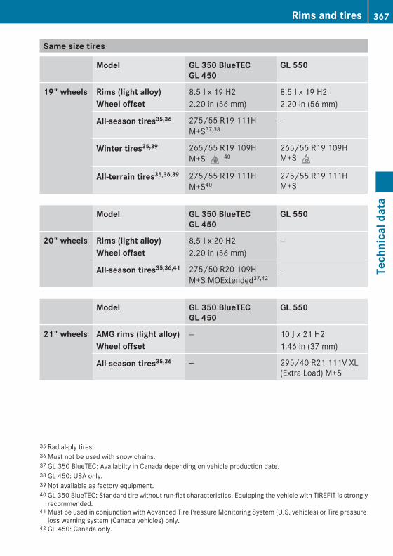
Same size tires
Model GL 350 BlueTECGL 450
GL 550
19" wheels Rims (light alloy)Wheel offset
8.5 J x 19 H22.20 in (56 mm)
8.5 J x 19 H22.20 in (56 mm)
All-season tires35,36 275/55 R19 111HM+S37,38
—
Winter tires35,39 265/55 R19 109HM+Si40
265/55 R19 109HM+Si
All-terrain tires35,36,39 275/55 R19 111HM+S40
275/55 R19 111HM+S
Model GL 350 BlueTECGL 450
GL 550
20" wheels Rims (light alloy)Wheel offset
8.5 J x 20 H22.20 in (56 mm)
—
All-season tires35,36,41 275/50 R20 109HM+S MOExtended37,42
—
Model GL 350 BlueTECGL 450
GL 550
21" wheels AMG rims (light alloy)Wheel offset
— 10 J x 21 H21.46 in (37 mm)
All-season tires35,36 — 295/40 R21 111V XL(Extra Load) M+S
35 Radial-ply tires.36 Must not be used with snow chains.37 GL 350 BlueTEC: Availabilty in Canada depending on vehicle production date.38 GL 450: USA only.39 Not available as factory equipment.40 GL 350 BlueTEC: Standard tire without run-flat characteristics. Equipping the vehicle with TIREFIT is strongly
recommended.41 Must be used in conjunction with Advanced Tire Pressure Monitoring System (U.S. vehicles) or Tire pressure
loss warning system (Canada vehicles) only.42 GL 450: Canada only.
Rims and tires 367
Tech
nica
l dat
a
X164_AKB; 5; 31, en-USd2ureepe, Version: 2.11.8.1
2009-09-11T12:30:16+02:00 - Seite 367
Z

Spare wheel
! Compare the recommended tire inflation pressure for your vehicle with the tire inflationpressure on the yellow label located on the spare wheel rim.If the tire inflation pressure on the yellow label on the spare wheel rim differs from the valuesgiven in this Operator’s Manual, inflate the tire to the recommended tire inflation pressuregiven on the yellow label on the spare wheel rim.
i Please note that the tire inflation pressure of the spare wheel differs from the tire inflationpressure of the road tires.
i The GL 350 BlueTEC does not have a spare wheel.
Model GL 450GL 550
Rim 4.5 B x 19 H2
Wheel offset 1.58 in (40 mm)
Minispare tire43 T 165/90 D19 119MorT 165/90 R19 119M
Recommended tire inflation pressure 61 psi (4.2 bar)
Fuels, coolants, lubricants, etc.
CapacitiesVehicle components and their respectivelubricants must match. Therefore only useproducts tested and approved by Mercedes-Benz.For information on tested and approvedproducts, contact an authorized Mercedes-Benz Center or visit www.mbusa.com (USAonly).
G Warning!Comply with all valid regulations with respectto handling, storing, and disposing of service
fluids. Otherwise you could endanger personsor the environment.Keep service fluids out of the reach ofchildren.For health reasons, you should preventservice fluids from coming into direct contactwith your skin or clothing.If a service fluid is swallowed, contact aphysician immediately.
43 Must not be used with snow chains.
368 Fuels, coolants, lubricants, etc.Te
chni
cal d
ata
X164_AKB; 5; 31, en-USd2ureepe, Version: 2.11.8.1
2009-09-11T12:30:16+02:00 - Seite 368

Model Capacity Fuels, coolants, lubricants, etc.
Engine with oil filter
GL 350 BlueTEC 9.0 US qt (8.5 l) Approved engineoils
GL 450GL 550
9.5 US qt (9.0 l)
Automatic transmission
All models 9.5 US qt (9.0 l) MB AutomaticTransmission Fluid
Front axle All models 1.2 US qt (1.1 l) Hypoid gear oil
Rear axle All models 1.2 US qt (1.1 l) Hypoid gear oil
Rear axle with differential lock
All models 1.7 US qt (1.6 l) Hypoid gear oil
Transfer case single speed
All models 0.53 US qt (0.5 l) MB AutomaticTransmission Fluid
Transfer case double speed
All models 1.6 US qt (1.5 l) MB AutomaticTransmission Fluid
Power steering All models approx. 1.1 US qt (1.0 l) MB Power SteeringFluid or approvedDexron III ATF
Brake system All models 0.63 US qt (0.6 l) MB Brake Fluid(DOT 4+)
Cooling system GL 350 BlueTEC approx. 10.0 US qt (9.5 l) MB 325.0Anticorrosion/AntifreezeGL 450
GL 550approx. 12.7 US qt (12.0 l)
Fuel tank All models 26.4 US gal (100.0 l) Gasoline engine:Premium unleadedgasoline (MinimumPosted Octane 91[Avg. of96 RON/86 MON])Diesel engine:ULTRA-LOWSULFUR HIGHWAYDIESEL FUEL(ULSD, 15 ppmSULFUR MAXIMUM)
Fuel tank reserve
All models approx. 3.4 US gal (13.0 l)
AdBlue® tank GL 350 BlueTEC 8.3 US gal (31.7 l) AdBlue® complyingwith ISO 22241
Fuels, coolants, lubricants, etc. 369
Tech
nica
l dat
a
X164_AKB; 5; 31, en-USd2ureepe, Version: 2.11.8.1
2009-09-11T12:30:16+02:00 - Seite 369
Z

Model Capacity Fuels, coolants, lubricants, etc.
Air conditioning system
All models — R134a refrigerantand specialPAG lubricant oil(never R 12)
Washer system and headlamp cleaning system
All models 7.6 US qt (7.2 l) MB WindshieldWasherConcentrate44
(Y page 375)Washer fluid mixingratio (Y page 375)
Approved engine oilsEngine oils are specifically tested for theirsuitability in our engines and durability for ourservice intervals. Therefore, only useapproved engine oils and oil filters requiredfor vehicles with the Maintenance System.For a listing of approved engine oils and oilfilters, contact an authorized Mercedes-BenzCenter or visit www.mbusa.com (USA only).
! Using engine oils and oil filters of aspecification other than those expresslyrequired for the Maintenance System, orchanging of oil and oil filter at changeintervals longer than those called for by theMaintenance System will result in engine oremission control system damage notcovered by the Mercedes-Benz LimitedWarranty.Please follow Maintenance Systemrecommendations for scheduled oilchanges. Failure to do so will result inengine or emission control system damagenot covered by the Mercedes-Benz LimitedWarranty.
Mercedes-Benz recommends MOBIL OIL.
Use the table below to determine theMB sheet number.
Model Engine,type
MB sheetnumber
GL 350 BlueTEC 642 229.51
GL 450 273 229.5
GL 550 273 229.5
i MB sheet numbers are printed on theoutside of oil containers.
Viscosity grades for engine oilsUsing the chart below, select oil viscosityaccording to the lowest air temperatureexpected before the next oil change.
44 Mixed with water or commercially available premixed washer solvent/antifreeze.
370 Fuels, coolants, lubricants, etc.Te
chni
cal d
ata
X164_AKB; 5; 31, en-USd2ureepe, Version: 2.11.8.1
2009-09-11T12:30:16+02:00 - Seite 370

Engine oil additives! Do not blend oil additives with engine oil.
They may damage the engine. Damage ormalfunctions resulting from blending oiladditives are not covered by the Mercedes-Benz Limited Warranty.
Air conditioning refrigerantR134a (HFC) refrigerant and special PAGlubricating oil are used in the air conditioningsystem.
! Never use R 12 (CFC) or mineral-basedlubricating oil. Otherwise damage to thesystem will occur.
Brake fluid
G Warning!During vehicle operation, the boiling point ofthe brake fluid is continuously reducedthrough the absorption of moisture from theatmosphere.Under extremely strenuous operatingconditions, this moisture content can lead tothe formation of bubbles in the system, thusreducing the system’s efficiency.Therefore, the brake fluid must be replacedregularly. Refer to your vehicle’s MaintenanceBooklet for replacement interval.
Only brake fluid approved by Mercedes-Benzis recommended. Any authorized Mercedes-Benz Center will provide you with additionalinformation.
Premium unleaded gasoline (gasoline engine)
G Warning!Gasoline is highly flammable and poisonous.It burns violently and can cause seriouspersonal injury.
Never allow sparks, flames or smokingmaterials near gasoline!Turn off the engine before refueling.Whenever you are around gasoline, avoidinhaling fumes and any skin or clothingcontact. Extinguish all smoking materials.Direct skin contact with fuels and theinhalation of fuel vapors are damaging yourhealth.
! To maintain the engine’s durability andperformance, premium unleaded gasolinemust be used.If premium unleaded gasoline is notavailable and low octane gasoline is used,follow these precautions:RHave the fuel tank only partially filled
with unleaded regular gasoline and fill upwith premium unleaded gasoline as soonas possible.RAvoid full throttle driving and abrupt
acceleration.RDo not exceed an engine speed of
3 000 rpm if the vehicle is loaded with alight load such as two persons and noluggage.RDo not exceed 2/3 of maximum
accelerator pedal position if the vehicleis fully loaded or operating inmountainous terrain.
Fuel requirements
Gasoline engineOnly use premium unleaded gasoline. Theoctane number (posted at the pump) must be91 min. It is an average of both the ResearchOctane Number (RON) and the Motor OctaneNumber (MON): (RON+MON)/2. This is alsoknown as the ANTI-KNOCK INDEX.Reformulated gasolines (RFG) and/orunleaded gasoline containing oxygenatessuch as ethanol, TAME, ETBE, IPA, IBA, and
Fuels, coolants, lubricants, etc. 371
Tech
nica
l dat
a
X164_AKB; 5; 31, en-USd2ureepe, Version: 2.11.8.1
2009-09-11T12:30:16+02:00 - Seite 371
Z

TBA can be used provided the ratio of any oneof these oxygenates to gasoline does notexceed 10%; MTBE must not exceed 15%.The ratio of methanol to gasoline must notexceed 3% plus additional cosolvents.Using mixtures of ethanol and methanol is notallowed. Gasohol, which contains 10%ethanol and 90% unleaded gasoline, can beused.These blends must also meet all other fuelrequirements, such as resistance to sparkknock, boiling range, vapor pressure, etc.
Diesel engine Only use commercially available vehicularULTRA-LOW SULFUR HIGHWAY DIESEL FUEL(ULSD, 15 ppm SULFUR MAXIMUM) thatmeets the ASTM D975 standard. Failure touse ULTRA-LOW SULFUR HIGHWAY DIESELFUEL (ULSD) can severely damage thevehicle’s exhaust after-treatment device.To prevent malfunctions, diesel fuel withimproved cold flow characteristics is offeredin the winter months. Check with your fuelretailer.
! Do not fill the tank with gasoline. Do notblend diesel fuel with gasoline or kerosene.The fuel system and engine will otherwisebe damaged, which is not covered by theMercedes-Benz Limited Warranty.
For further information on diesel fuel pumplabeling, contact an authorized Mercedes-Benz Center or visit www.mbusa.com (USAonly).
Biodiesel (FAME = Fatty Acid Methyl Ester) containing fuelsMercedes-Benz USA approves the use of B5(standard ULSD which may contain amaximum of 5% biodiesel) in all Common-railinjection (CDI) and BlueTEC diesel engines.Diesel fuels containing a higher percentage ofbiodiesel, e.g. B20, as well as straightbiodiesel may cause severe damage to yourengine/fuel system and are not approved.
Please ask your service station personnel forfurther information. If the B5 biodiesel blendis not sufficiently labeled to clearly indicatethat it meets the ULSD standard, please donot use it.The Mercedes-Benz Limited Warranty doesnot cover damages caused by the use of fuelsnot meeting Mercedes-Benz approved fuelstandards.
Gasoline additives (gasoline engine)A major concern among enginemanufacturers is carbon build-up caused bygasoline. Mercedes-Benz recommends onlythe use of quality gasoline containingadditives that prevent the build-up of carbondeposits.After an extended period of using fuelswithout such additives carbon deposits canbuild up, especially on the intake valves andin the combustion area, leading to engineperformance problems such as:RWarm-up hesitationRUnstable idleRKnocking/pingingRMisfireRPower lossIn areas where carbon deposits may beencountered due to lack of availability ofgasoline which contains these additives, theuse of Mercedes-Benz approved additives isrecommended.Contact an authorized Mercedes-Benz Centeror visit www.mbusa.com (USA only) for alisting of approved products. Followdirections on the product label.Do not blend other fuel additives with fuel.This only results in unnecessary cost and maybe harmful to the engine operation.
! Damage or malfunction resulting frompoor fuel quality or from blending additionalfuel additives other than those tested andapproved by us for use on Mercedes-Benz
372 Fuels, coolants, lubricants, etc.Te
chni
cal d
ata
X164_AKB; 5; 31, en-USd2ureepe, Version: 2.11.8.1
2009-09-11T12:30:16+02:00 - Seite 372

vehicles are not covered by the Mercedes-Benz Limited Warranty or by any pre-ownedor Extended Limited Warranties.
AdBlue®
AdBlue® is a non-flammable, non-toxic,colorless and odorless, water-soluble liquid.
! Only use AdBlue® complying withISO 22241. Do not blend with additives.
! Rinse surfaces that have come intocontact with AdBlue®, or remove AdBlue®
with a moist cloth and cold waterimmediately. If AdBlue® has crystallizedalready, use cold water and a sponge.AdBlue® residues will crystallize and soilthe affected surfaces.
High ambient temperaturesIf AdBlue® in the reservoir heats up to above122‡ (50†) for a long period of time, forexample due to direct sunlight, ammonia gasvapors may escape when opening theAdBlue® tank.
G Warning!When opening the filler cap of the AdBlue®
tank ammonia gas vapors may escape. RefillAdBlue® in a well ventilated area only.Ammonia gas vapors have a pungent odor andare particularly irritating for your skin,mucous membranes, and eyes. Inhalingammonia gas vapors will cause burning eyes,nose, and throat, as well as coughing andwatering eyes.
Low ambient temperaturesAdBlue® freezes at a temperature ofapproximately 12‡ (-11†). Your vehicle isfactory equipped with an AdBlue® preheatingsystem. The vehicle can thus be operated attemperatures below 12‡ (-11†).
Special additives
! Only use AdBlue® complying withISO 22241. Do not add additives toAdBlue® and do not dilute AdBlue® withwater. Otherwise, the BlueTEC exhaust gasaftertreatment system could be damaged.Damage caused by using additives ordiluting with water are not covered by theMercedes-Benz Limited Warranty.
PurityThe purity of AdBlue® is of particularimportance for avoiding malfunctions in theexhaust gas aftertreatment.If AdBlue® is pumped out of the tank, e.g.during repair work, the same liquid must notbe used to refill the tank as its purity is nolonger guaranteed.
! Impurities caused for example by otherservice products, cleaning agents, and dustresult in increased emissions,malfunctions, catalyst damage, or enginedamage.
CoolantsThe engine coolant is a mixture of water andanticorrosion/antifreeze, which provides:RCorrosion protectionRFreeze protectionRBoiling protection (by increasing the boiling
point)The cooling system was filled at the factorywith a coolant providing freeze protection toapproximately -35‡ (-37†) and corrosionprotection.
! Add premixed coolant solution only.Adding water and MB 325.0 Anticorrosion/Antifreeze separately from each other,could cause engine damage not covered bythe Mercedes-Benz Limited Warranty.
Fuels, coolants, lubricants, etc. 373
Tech
nica
l dat
a
X164_AKB; 5; 31, en-USd2ureepe, Version: 2.11.8.1
2009-09-11T12:30:16+02:00 - Seite 373
Z

If the antifreeze mixture is effective to -35‡(-37†), the boiling point of the coolant in thepressurized cooling system is reached atapproximately 266‡ (130†).The coolant solution must be used year roundto provide the necessary corrosion protectionand increase boil-over protection. Refer tothe Maintenance Booklet for replacementinterval.Coolant system design and coolant useddetermine the replacement interval. Thereplacement interval published in theMaintenance Booklet is only applicable ifMB 325.0 Anticorrosion/Antifreeze solutionor other Mercedes-Benz approved productsof equal specification are used to renew thecoolant concentration or bring it back up tothe proper level.For information on other Mercedes-Benzapproved products of equal specification,contact an authorized Mercedes-Benz Centeror visit www.mbusa.com (USA only).To provide important corrosion protection,the solution must be at least 50%anticorrosion/antifreeze (equivalent tofreeze protection to approximately -35‡[-37†]).If you use a solution that is more than 55%anticorrosion/antifreeze (freeze protectionto approximately -49‡ [-45†]), the enginetemperature will increase due to the lowerheat transfer capability of the solution.Therefore, do not use more than this amountof anticorrosion/antifreeze.
If the coolant level is low, water and MB 325.0Anticorrosion/Antifreeze should be used tobring it up to the proper level (have coolingsystem checked for signs of leakage). Pleasemake sure the mixture is in accordance withlabel instructions.The water in the cooling system must meetminimum requirements, which are usuallysatisfied by normal drinking water.If you are not sure about the water quality,contact an authorized Mercedes-BenzCenter.
Anticorrosion/antifreeze Your vehicle contains a number of aluminumparts. The use of aluminum components inmotor vehicle engines necessitates thatanticorrosion/antifreeze coolant used insuch engines be specifically formulated toprotect the aluminum parts. Failure to usesuch anticorrosion/antifreeze coolant willresult in a significantly shortened service life.Therefore, the following product is stronglyrecommended for use in your vehicle:MB 325.0 Anticorrosion/Antifreeze agent.Before the start of the winter season (or oncea year in hot southern regions), you shouldhave the anticorrosion/antifreezeconcentration checked.The coolant is also regularly checked eachtime you bring your vehicle to an authorizedMercedes-Benz Center for service.
Model Approximate freeze protection
-35‡ (-37†) -49‡ (-45†)
Cooling system GL 350 BlueTEC 5.0 US qt (4.75 l) 5.5 US qt (5.2 l)
GL 450GL 550
6.3 US qt (6.0 l) 7.0 US qt (6.6 l)
374 Fuels, coolants, lubricants, etc.Te
chni
cal d
ata
X164_AKB; 5; 31, en-USd2ureepe, Version: 2.11.8.1
2009-09-11T12:30:16+02:00 - Seite 374

Washer system and headlamp cleaning system
G Warning!Washer solvent/antifreeze is highlyflammable. Do not spill washer solvent/antifreeze on hot engine parts, because it mayignite and burn. You could be seriouslyburned.
X Use MB Windshield Washer Concentrate“MB SummerFit”.
X Mix with water for temperatures abovefreezing point.
X Mix with commercially available premixedwasher solvent/antifreeze fortemperatures below freezing point.
Washer fluid mixing ratio For temperatures above the freezing point:1 part “MB SummerFit” to 100 parts water(1.34 fl oz [40 ml] “MB SummerFit” to 1 gal[4.0 l] water)For temperatures below freezing point:1 part “MB SummerFit” to 100 parts solvent(1.34 fl oz [40 ml] “MB SummerFit” to 1 gal[4.0 l] solvent)
Fuels, coolants, lubricants, etc. 375
Tech
nica
l dat
a
X164_AKB; 5; 31, en-USd2ureepe, Version: 2.11.8.1
2009-09-11T12:30:16+02:00 - Seite 375
Z

376
X164_AKB; 5; 31, en-USd2ureepe, Version: 2.11.8.1
2009-09-11T12:30:16+02:00 - Seite 376

Service and LiteratureYour authorized Mercedes-Benz Center hastrained technicians and Genuine Mercedes-Benz Parts to service your vehicle properly.For expert advice and quality service, contactan authorized Mercedes-Benz Center.If you are interested in obtaining serviceliterature for your vehicle, please contact anauthorized Mercedes-Benz Center.We consider this the best way for you toobtain accurate information for your vehicle.For further information you can find us on theMercedes-Benz web site www.mbusa.com(USA only) or www.mercedes-benz.ca(Canada only).
G Warning!To help avoid personal injury, be extremelycareful when performing any service work orrepairs. Improper or incomplete service or theuse of incorrect or inappropriate parts ormaterials may damage the vehicle or itsequipment, which may in turn result inpersonal injury.If you have any questions about carrying outany type of service, turn to the advice of anauthorized Mercedes-Benz Center.
We reserve the right to make changes indesign and equipment.Therefore, information, illustrations anddescriptions in this Operator’s Manual mightdiffer from your vehicle.Reprinting, translation and copying, even ofexcerpts, is not permitted without our priorauthorization in writing.Press time September 11, 2009GSP/OISPrinted in U. S. A.
X164_AKB; 5; 31, en-USd2ureepe, Version: 2.11.8.1
2009-09-11T12:30:16+02:00 - Seite 377

Order no. 6515 4318 13 Part no. 164 584 15 83 Edition B 2010
É1645841583&ËÍ1645841583
X164_AKB; 5; 31, en-USd2ureepe, Version: 2.11.8.1
2009-09-11T12:30:16+02:00 - Seite 378