gb - riba product selector · analysis and evaluations from an ergonomic ... • flexible technical...
TRANSCRIPT

PlanningGuide
© G
uldm
ann
Stepless – Access for allUnder the Stepless brand we sell accessibility– accessibility that gives the walking-impaired,wheelchair users and others on wheels accessto their surroundings.• Portableramps&doorstepramps• Platformlifts• Bespokeplatformlifts
Guldmann – Time to careUnder the Guldmann brand we are engaged primarily in improving the overall working environment within the health care sector, where people need assistance being moved, liftedandpositioned.
Guldmann Consulting – Competence programs Tailor-made educational programs, project courses, topic days, seminars, lectures, analysisandevaluationsfromanergonomicperspective.Ourparticularareaofexpertiseisthe physical working environment surrounding thetransfer,mobilizationandrehabilitationofpeople/patients.
V. Guldmann A/SGrahamBellsVej21-23ADK-8200 AahusNTlf. +4587413100Fax +4587413131E-mail [email protected]
GB


3
Stepless planning guide
The purpose of the Stepless planning guide is to offer architects, consulting engineers, and others who work with access conditions a tool that can help them to plan access solutions incorporating ramps and lifting platforms.
In recent years the focus on improving physical access in private homes and public and private buildings has been sharpened. The aim of this is to give people with reduced mobility greater independence, more freedom of movement, and heightened safety, and thereby improve their quality of life.
The Stepless division at V. Guldmann A/S has specialised in accessibility for the purpose of creating access solutions for people with reduced mobility. Our intention with this product/architect guide is to pass on vital information so that physical access conditions can be optimised. The contents of this guide cannot provide a solution to all problems as these vary from place to place. We therefore recommend that it is used as a planning guide and ask you to contact us for professional advice in connection with concrete projects.
In addition to professional advice regarding accessibility, we offer:
• Needs analyses and surveys• Our own project department• Flexible technical aids in attractive designs• A wide range of products that promote accessibility • Or put differently – turnkey solutions in the field of accessibility
Guldmann has also prepared a planning guide for architects that simplifies planning ceiling hoist systems. This guide can be ordered from Guldmann’s Export Department.
Yours faithfully,Stepless by Guldmann
V. Guldmann A/SGraham Bells Vej 21-23ADK-8200 Aarhus N, DenmarkTlf. +45 8741 3100Fax +45 8741 3131E-mail [email protected]. nr. 27 70 67 46

4
© G
uldm
ann
1627
/04/
16

Stepless develops, manufactures,distributes and maintains products and
services that makes it possible to efficiently negotiate physical barriers due to
differences in level.
INTRO
CONSIDERATIONS
SOLUTIONS
STANDARD AND LEGISLATION
PLANNING GUIDE
Vers. 022

6
© G
uldm
ann
1627
/04/
16

7
© G
uldm
ann
1627
/04/
16
INTROV. Guldmann A/S – company profile . . . . . . . . . . . . . . . . 10
CONSIDERATIONSNeeds analysis in connection with establishing access conditions . . . . . . . . . . . . . . . . . . . . . 12Choice of lifting platform . . . . . . . . . . . . . . . . . . . . . . . . 13Recommended dimensions in connection with turning radiuses for various wheelchairs/rollators . . . . . . 14
SOLUTIONS
RAMPS . . . . . . . . . . . . . . . . . . . . . . . . . . . . . . . . . 18Portable ramps . . . . . . . . . . . . . . . . . . . . . . . . . . . . . . . . 19Lite Ramps . . . . . . . . . . . . . . . . . . . . . . . . . . . . . . . . . . 21Excellent ramp kits . . . . . . . . . . . . . . . . . . . . . . . . . . . . . 22Doorstep ramps & cover plates . . . . . . . . . . . . . . . . . . . . 23
LIFTING PLATFORMS . . . . . . . . . . . . . . . . . . . . . . . . 24Vertical lifting platform LP1 . . . . . . . . . . . . . . . . . . . . . . . 24
Technical specifications . . . . . . . . . . . . . . . . . . . . . . . . 25Installation dimensions . . . . . . . . . . . . . . . . . . . . . . . . 26
Vertical lifting platform LP5 . . . . . . . . . . . . . . . . . . . . . . . 27Technical specifications . . . . . . . . . . . . . . . . . . . . . . . . 28Platform installation / recessing . . . . . . . . . . . . . . . . . 29Platform installation / Built-in dimensions . . . . . . . . . . 30
Vertical lifting platform LP5+. . . . . . . . . . . . . . . . . . . . . . 31Technical specifications . . . . . . . . . . . . . . . . . . . . . . . . 32Platform installation / recessing . . . . . . . . . . . . . . . . . 33Platform installation / Built-in dimensions . . . . . . . . . . 34
Vertical lifting platform LP50 & LP50H . . . . . . . . . . . . . . 35Technical specifications . . . . . . . . . . . . . . . . . . . . . . . . 36
Vertical lifting platform LP11 . . . . . . . . . . . . . . . . . . . . . . 37Technical specifications . . . . . . . . . . . . . . . . . . . . . . . . 38
Vertical lifting platform LP8 . . . . . . . . . . . . . . . . . . . . . . . 39Technical specifications . . . . . . . . . . . . . . . . . . . . . . . . 40Main dimensions . . . . . . . . . . . . . . . . . . . . . . . . . . . . . 41Installation dimensions . . . . . . . . . . . . . . . . . . . . . . . . 42
Lifting platforms . . . . . . . . . . . . . . . . . . . . . . . . . . . . . . . 44 Control panels . . . . . . . . . . . . . . . . . . . . . . . . . . . . . . 44
STANDARDS AND LEGISLATIONStandards and legislation in connection with negotiating height differences . . . . . . . . . . . . . . . . . . . . 48Building reulations . . . . . . . . . . . . . . . . . . . . . . . . . . . . . 49EN 81-41: Lifting platforms . . . . . . . . . . . . . . . . . . . . . . . 50

8
© G
uldm
ann
1627
/04/
16

9
© G
uldm
ann
1627
/04/
16
INTR
O INTROV. Guldmann A/S – company profile . . . . . . . . . . . . . . . . 10

10
INTR
O©
Gul
dman
n 16
27/0
4/16
Guldmann in briefV. Guldmann A/S was established in 1980 by Viggo Guldmann with the concept to develop, manufacture and market technical aids for the disabled and working tools for their carers.
Today we supply products and services within three main areas and under three trademarks.
1. Guldmann Under the Guldmann brand we are engaged primarily in improving the overall working environment within the social sector, where people need assistance being moved, lifted and positioned:• Ceiling hoist systems• Rail systems• Mobile lifting systems• Slings• Beds
2. SteplessUnder the Stepless brand we sell accessibility– accessibility that gives the walking-impaired,wheelchair users and others on wheels accessto their surroundings:• Portable ramps & doorstep ramps• Lifting platforms
3. Guldmann Consulting Tailor-made educational programmes, project courses, topic days, seminars, lectures, analyses and evaluations from an ergonomic perspective. Our particular area of expertise is the physical working environment surrounding the transfer, mobilisation and rehabilitation of people/patients.
An international companyWe have customers all over the world and they are being serviced from one of our sales offices in Denmark, Sweden, Germany, Italy, France, England and the USA or via our distributors who cover markets from Iceland in the north to Australia in the south.
Facts about GuldmannStarted 1980Number of employees 330Headquarters DenmarkCVR-nr. 27 70 67 46Share capital DKK 600,000Owner Guldmann Holding A/SBank SydbankAccountants DeloitteMember of Danish Rehabilitation Group
The Confederation of Danish Industries
Guldmann’s FACT of life
FlexibilityWe know and we act according to the fact that what is right today may be wrong tomorrow – we do not have a monopoly of the truth.
AmbitionsWe set common ambitious goals and strive for improvements.
CompetenceWe know what we are talking about. The capability and knowledge of the individual is our common strength.
TrustworthinessWe aspire to instill confidence in us through confidence in each other.
V. Guldmann A/S – company profile
11
© G
uldm
ann
1627
/04/
16
CONS
IDER
ATIO
NS CONSIDERATIONSNeeds analysis in connection with establishing access conditions . . . . . . . . . . . . . . . . . . . . . 12Choice of lifting platform . . . . . . . . . . . . . . . . . . . . . . . . 13Recommended dimensions in connection with turning radiuses for various wheelchairs/rollators . . . . . . 14

12
CONS
IDER
ATIO
NS©
Gul
dman
n 16
27/0
4/16
Needs analysis in connection with establishing access conditions
Stepless has drawn up a list of the most important issues that should be clarified before deciding which product to use in a given situation. The list takes its point of departure in the Stepless needs analysis:
Stepless needs analysis
By identifying the eight core areas it is possible to plan and select the aid facility that is most suitable for the place in question. Places with restricted space, for example, will exclude such products as a long ramp system.
SurroundingsEvaluate the surroundings, including space and the situation regarding use, as well as whether this is public or private.
Technical areasEvaluate the technical aspects, including which lifting capacity is required, size, etc.
End-UserEvaluate who and how well-functioning the useris, and which technical aids the user has (manualor electric wheelchair, scooter, etc.).
Price levelFind out which price level has been budgeted for.
LengthFind out lengths, differences in levels, and how much space there is.
ExtraFind out whether it is necessary to order extra accessories, or whether to establish additional lighting, alarm systems, etc., in order to ensure optimum use.
Standards and legislationStandards and legislation, including building regulations that must be complied with.
Stepless consultant's visitConsider whether there is a need for a Stepless consultant to handle surveys, planning, advice, etc.
PRODUCT
S
T
E
P
L
E
S
S

13
CONS
IDER
ATIO
NS©
Gul
dman
n 16
27/0
4/16
Choice of lifting platform
(According to EN 81-41 & ISO 9386-1 - Extract)
IntroductionThis guidance is to assist in the selection of a suitable powered lifting platform.
SuitabilityWhen selecting a powered lifting platform, consider if the needs of the user are likely to change in the future.
Select a lifting platform with a rated load that is capable of carrying the maximum foreseeable load.
Where either manual or automatic operation are optionally available for devices such as doors, barriers or hinged platforms, consider which is more appropriate for the user.
Control (operating) devicesConsider the position, type and number of operating controls that would suit users with differing disabilities.
Consider whether a key switch, electronic card, or similar means is necessary to restrict the use of the lifting platform to authorised users.
Location of the lifting platformCheck if the proposed location of the lifting platform is suitable. For example, check the following:
a) that the installation will not obstruct normal activities in and around the building
b) that the site location and proposed supporting structure is strong enough to support the lifting platform
c) that adequate wheelchair manoeuvring space will be available at each landing level served (approx. 1500 x 1500 mm)
Electrical supply and lightingEnsure that a suitable electrical supply is available.Ensure that adequate lighting is available on the landings.
Operating/emergency instructionsEnsure that operation of the lifting platform is demonstrated to the user and that the user is fully instructed on its safe use, including
a) instruction on the correct emergency operating procedure in the case of breakdown
b) the names, addresses and telephone numbers of persons to contact for emergency services
MaintenanceEnsure that the purchaser is informed of the requirements for the examination, testing and servicing of the lifting platform and of any associated national regulatory requirements.
Alarm systemConsideration should be given to the desirability of providing an alarm system.

14
CONS
IDER
ATIO
NS©
Gul
dman
n 16
27/0
4/16
Recommended dimensions in connection with turning radiuses for various wheelchairs/rollators
1. Rollator Rollator and user
0.60 x 1.00 m 90° turn 1.10 x 1.10 m 180° turn 1.30 x 1.30 m 360° turn 1.40 x 1.40 m
2. Manual wheelchair Wheelchair and user
0.75 x 1.20 m 90° turn 1.40 x 1.40 m 180° turn 1.50 x 1.50 m 360° turn 1.70 x 1.70 m
3. Electric wheelchair – indoors and out Wheelchair and user
0.70 x 1.30 m 90° turn 1.60 x 1.60 m 180° turn 1.85 x 1.85 m 360° turn 2.10 x 2.10 m

15
CONS
IDER
ATIO
NS©
Gul
dman
n 16
27/0
4/16
Recommended dimensions in connection with turning radiuses for various wheelchairs/rollators
4. Scooter/ Electric wheelchair – outside Scooter and user
0.70 x 1.50 m 90° turn 2.00 x 2.00 m 180° turn 2.25 x 2.25 m 360° turn 2.50 x 2.50 m
5. Manual wheelchair Wheelchair, user and helper
0.75 x 1.75 m 90° turn 1.75 x 1.75 m 180° turn 1.75 x 1.75 m 360° turn 1.75 x 1.75 m
6. Comfort wheelchair Wheelchair, user and helper
0.75 x 2.00 m 90° turn 2.10 x 2.10 m 180° turn 2.10 x 2.10 m 360° turn 2.10 x 2.10 m
Recommended dimensions for necessary manoeuvring area for various types
of wheelchair, wheelchairs with helpers, patient hoists, and ceiling-mounted
patient hoists (all measurements in metres). There may be special needs in
accommodation designed for the elderly and the handicapped with a need
for care, cf. chapter 8.
Source:
Accessibility for all, figur 2.1, p. 14
DS 3028:2001, 1. edition
Dansk Standard, Kollegievej 6, 2920 Charlottenlund

16
© G
uldm
ann
1627
/04/
16

17
© G
uldm
ann
1627
/04/
16
SOLU
TIO
NSList of solutions
50 cm
50 cm
87,5 cm
300 cm
60 cm
50/75
cm
100 cm
RAMPS . . . . . . . . . . . . . . . . . . . . . . . . . . . . . . . . . 18Portable ramps . . . . . . . . . . . . . . . . . . . . . . . . 19Lite Ramps . . . . . . . . . . . . . . . . . . . . . . . . . . . 21Excellent ramp kits . . . . . . . . . . . . . . . . . . . . . 22Doorstep ramps & cover plates . . . . . . . . . . . . 23
LIFTING PLATFORMS . . . . . . . . . . . . . . . . . . . . . . . . 24Vertical lifting platform LP1 . . . . . . . . . . . . . . . 24 Technical specifications . . . . . . . . . . . . . . . . 25 Installation dimensions . . . . . . . . . . . . . . . . 26
Vertical lifting platform LP5 . . . . . . . . . . . . . . . 27 Technical specifications . . . . . . . . . . . . . . . . 28 Platform installation / recessing . . . . . . . . . 29 Platform installation / Built-in dimensions . . 30
Vertical lifting platform LP5+ . . . . . . . . . . . . . . 31 Technical specifications . . . . . . . . . . . . . . . . 32 Platform installation / recessing . . . . . . . . . 33 Platform installation / Built-in dimensions . . 34
Vertical lifting platform LP50 & LP50H . . . . . . . 35 Technical specifications . . . . . . . . . . . . . . . . 36
Vertical lifting platform LP11 . . . . . . . . . . . . . . 37 Technical specifications . . . . . . . . . . . . . . . . 38
Vertical lifting platform LP8 . . . . . . . . . . . . . . . 39 Technical specifications . . . . . . . . . . . . . . . . 40 Main dimensions . . . . . . . . . . . . . . . . . . . . . 41 Installation dimensions . . . . . . . . . . . . . . . . 42
Lifting platforms . . . . . . . . . . . . . . . . . . . . . . . 44 Control panels . . . . . . . . . . . . . . . . . . . . . . . . 44

18
© G
uldm
ann
1627
/04/
16
R A M P S

19
SOLU
TIO
NS©
Gul
dman
n 16
27/0
4/16
Portable rampsTechnical specifications
Item no. Type Max/min Inner Outer Width Max Weight length width width folded load mm mm max. mm max. mm kg/pair kg/each
30000-050 Plain ramp 500 182 260 - 350 1.5
30000-105 Plain ramp 1050 182 260 - 350 3.2
30000-130 Plain ramp 1300 182 260 - 350 3.9
30000-155 Plain ramp 1550 182 260 - 350 4.7
30000-200 Plain ramp 2000 182 260 - 350 6.0
30015-100 Telescopic ramp 1000/677 182 279 - 350 4.3
30015-150 Telescopic ramp 1500/927 182 279 - 350 5.7
30015-200 Telescopic ramp 2000/1177 182 279 - 350 7.2
30015-250 Telescopic ramp 2500/1427 182 279 - 200 8.6
30015-300 Telescopic ramp 3000/1677 182 279 - 200 10.1
30020-110 Folding ramp 1100/580 182 260 - 350 4.0
30020-160 Folding ramp 1600/830 182 260 - 350 5.7
30020-210 Folding ramp 2100/1080 182 260 - 350 7.2
30020-260 Folding ramp 2600/1330 182 260 - 200 8.6
30020-310 Folding ramp 3100/1580 182 260 - 200 10.1
30030-100 Wide plain ramp 1000 770 880 - 325 9.7
30030-125 Wide plain ramp 1250 770 880 - 325 12.1
30030-150 Wide plain ramp 1500 770 880 - 325 14.4
30030-200 Wide plain ramp 2000 770 880 - 325 19.1
30030-300 Wide plain ramp 3000 770 880 - 200 28.6
30040-150 Wide folding ramp 1500/780 770 880 - 325 17.5
30040-200 Wide folding ramp 2000/1030 770 880 - 325 22.2
30040-250 Wide folding ramp 2500/1280 770 880 - 200 26.9
30040-300 Wide folding ramp 3000/1530 770 880 - 200 31.7
30070-180 EasyFold Telescopic ramp 1830/1120 760 820 405 325 16.4
30070-210 EasyFold Telescopic ramp 2130/1270 760 820 405 325 18.9
30070-240 EasyFold Telescopic ramp 2440/1430 760 820 405 325 21.4
30070-300 EasyFold Telescopic ramp 3050/1730 760 820 405 200 26.4
30080-095 EasyFold Pro ramp 935 760 776 398 350 7.8
30080-120 EasyFold Pro ramp 1185 760 776 398 350 9.0
30080-150 EasyFold Pro ramp 1485 760 776 398 350 11.4
30080-180 EasyFold Pro ramp 1785 760 776 398 350 13.4
30080-210 EasyFold Pro ramp 2085 760 776 398 350 15.8
30085-165 EasyFold Pro3 ramp 1635 760 786 273 350 13.4
30000-xxx & 30030-xxx
30020-xxx & 30040-xxx
30015-xxx
30070-xxx
30080-xxx
30085-xxx

20
SOLU
TIO
NS©
Gul
dman
n 16
27/0
4/16
MaterialRamp slopes : Anodised aluminium with skid
resistant surfaceEnd profile and handle : Impact-proof and non-skid plasticBrackets : Stainless steel, glass blownBrakets 30080 : Plastic
Other measurementsHeight of edge : 46 mmHeight of edge 30080/85 : 40 mm/50 mmAngle of contact : max. 12 degreesContact surface, 30000/30015/30020 : 65 mm 30030/30040 : 110 mm 30070/30080/30085 : 90 mm
MarkingThe product is manufactured in compliance with the Council Directive 93/42/EEC of June 14th 1993, including amendments, as medical device class 1.
ClassificationAccording to ISO 9999 : 18 30 15
Portable rampsTechnical specifications
21
SOLU
TIO
NS©
Gul
dman
n 16
27/0
4/16
Lite RampsTechnical specifications
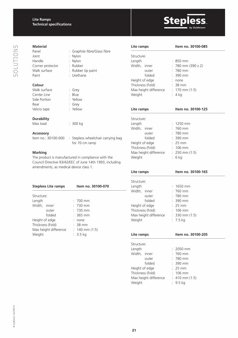
MaterialPanel : Graphite fibre/Glass fibreJoint : NylonHandle : NylonCorner protector : RubberWalk surface : Rubber tip paintPaint : Urethane
ColourWalk surface : GreyCenter Line : BlueSide Portion : YellowRear : GreyVelcro tape : Yellow
DurabilityMax load : 300 kg
AccessoryItem no.: 30100-000 : Stepless wheelchair carrying bag
for 70 cm ramp
MarkingThe product is manufactured in compliance with the Council Directive 93/42/EEC of June 14th 1993, including amendments, as medical device class 1.
Stepless Lite ramps Item no. 30100-070
Structure:Length : 700 mmWidth, inner : 730 mm outer : 730 mm folded : 365 mmHeight of edge : noneThickness (Fold) : 38 mmMax height difference : 140 mm (1:5)Weight : 3.5 kg
Lite ramps Item no. 30100-085
Structure:Length : 850 mmWidth, inner : 780 mm (390 x 2) outer : 780 mm folded : 390 mmHeight of edge : noneThickness (Fold) : 38 mmMax height difference : 170 mm (1:5)Weight : 4 kg
Lite ramps Item no. 30100-125
Structure:Length : 1250 mmWidth, inner : 760 mm outer : 780 mm folded : 390 mmHeight of edge : 25 mmThickness (Fold) : 106 mmMax height difference : 250 mm (1:5)Weight : 6 kg
Lite ramps Item no. 30100-165
Structure:Length : 1650 mmWidth, inner : 760 mm outer : 780 mm folded : 390 mmHeight of edge : 25 mmThickness (Fold) : 106 mmMax height difference : 330 mm (1:5)Weight : 7.5 kg
Lite ramps Item no. 30100-205
Structure:Length : 2050 mmWidth, inner : 760 mm outer : 780 mm folded : 390 mmHeight of edge : 25 mmThickness (Fold) : 106 mmMax height difference : 410 mm (1:5)Weight : 9.5 kg

22
SOLU
TIO
NS©
Gul
dman
n 16
27/0
4/16
Excellent ramp kitsTechnical specifications
Excellent ramp kits – doorstep ramps for many purposesStepless launches a new series of the popular Excellent ramp kits that offer even better adjustment possibilities. The new kits are available in 2 widths: 750 and 1000 mm and also in an outdoor version called “S” with SlipStop, which provides extra grip on the outdoor ramps.
The doorstep ramps are sold as kits which makes handling and installation easy. The two upper layers are loose to facilitate an accurate height adjustment. The ramp kits are available in various versions to compensate for differences in height up to 150 mm. They are delivered complete with instruction guide and fittings for setting-up and final adjustments.
The kit series also comprises the double-sided doorstep ramp with corner modules which has the same smooth driving surface as the new kits.
The Excellent doorstep ramps are environmentally friendly products – they are 100% PVC free, 100% nontoxic and have a maximum capacity in excess of one ton.
750 mm width
Item No. Type W x L x H mm
11-12100 Kit 0 – up to 24 mm 750 x 125 x 24
11-12101 Kit 1 – up to 42 mm 750 x 250 x 42
11-12102 Kit 2 – up to 78 mm 750 x 500 x 78
11-12103 Kit 3 – up to 114 mm 750 x 750 x 114
11-12104 Kit 4 – up to 150 mm 750 x 1000 x 150
11-12105 Kit Add-on1 – repair ¹) 750 x 62 x 15
750 mm width with SlipStop (outdoor use)
Item No. Type W x L x H mm
11-12112 Kit 1S – up to 42 mm 750 x 250 x 42
11-12113 Kit 2S – up to 78 mm 750 x 500 x 78
11-12114 Kit 3S – up to 114 mm 750 x 750 x 114
11-12115 Kit 4S – up to 150 mm 750 x 1000 x 150
¹ Kit Add-on1 - repair set Used for extra height adjustment up to 15 mm on Kit 1-4 or as a repair set when re-locating Kit 1-4.
² Kit Add-on100 - repair set Used for extra height adjustment up to 15 mm on Kit 101-104 or as a repair set when re-locating Kit 101-104.
1000 mm width
Item No. Type W x L x H mm
11-12106 Kit 100 – up to 24 mm 1000 x 125 x 24
11-12107 Kit 101 – up to 42 mm 1000 x 250 x 42
11-12108 Kit 102 – up to 78 mm 1000 x 500 x 78
11-12109 Kit 103 – up to 114 mm 1000 x 750 x 114
11-12110 Kit 104 – up to 150 mm 1000 x 1000 x 150
11-12111 Kit Add-on100 - repair ²) 1000 x 62 x 15
1000 mm width with SlipStop (outdoor use)
Item No. Type W x L x H mm
11-12116 Kit 101S – up to 42 mm 1000 x 250 x 42
11-12117 Kit 102S – up to 78 mm 1000 x 500 x 78
11-12118 Kit 103S – up to 114 mm 1000 x 750 x 114
11-12119 Kit 104S – up to 150 mm 1000 x 1000 x 150
Doorstep ramp with corner modules
Item No. Type W x L x H mm
11-12501 Package of 1 complete kitof doorstep ramps withcorner modules.Fits both sides of the doorstep.
Dimension on the low side:Dimension on the high side:
1000 x 125 x 211250 x 250 x 39

23
SOLU
TIO
NS©
Gul
dman
n 16
27/0
4/16
Doorstep ramps & cover platesTechnical specifications
Cover plate – for doorstepsA doorstep creates an impediment for wheelchairs, rollators and other equipment for disabled persons. This impediment can be permanently done away with by removing the existing doorstep and installing a Stepless cover plate over the hole that is created as a result.
Material: Extruded aluminium or bronze/champagne-coloured aluminium with incorporated non-slip surface (grooves). Load: 500 kg.
Doorstep rampThe doorstep ramp is placed over the existing doorstep and thereby eases approach from both sides.
Material: Bent 3 mm aluminium plate with black non-slip coveringLoad: 350 kg.
Item no. Type Length x width, mm
780105 Cover plate bronze/champagne-coloured, aluminium 1800 x 105
780130 Cover plate bronze/champagne-coloured, aluminium 1800 x 130
780155 Cover plate bronze/champagne-coloured, aluminium 1800 x 150
780180 Cover plate bronze/champagne-coloured, aluminium 1800 x 180
780199 Cover plate aluminium-coloured, aluminium (without grooves) 1800 x 50
780200 Cover plate aluminium-coloured, aluminium 1800 x 80
780201 Cover plate aluminium-coloured, aluminium 1800 x 105
780202 Cover plate aluminium-coloured, aluminium 1800 x 130
780204 Cover plate aluminium-coloured, aluminium 1800 x 150
780206 Cover plate aluminium-coloured, aluminium 1800 x 180
Weight, kg Max. load, kg Width x length x height, mm
39167 Doorstep ramp 3.4 350 670 x 600 x 25
39177 Doorstep ramp 4.3 350 770 x 600 x 25

24
© G
uldm
ann
1627
/04/
16
L P 1
Vertical lifting platform LP1
25
SOLU
TIO
NS©
Gul
dman
n 16
27/0
4/16
LP1Technical specifications
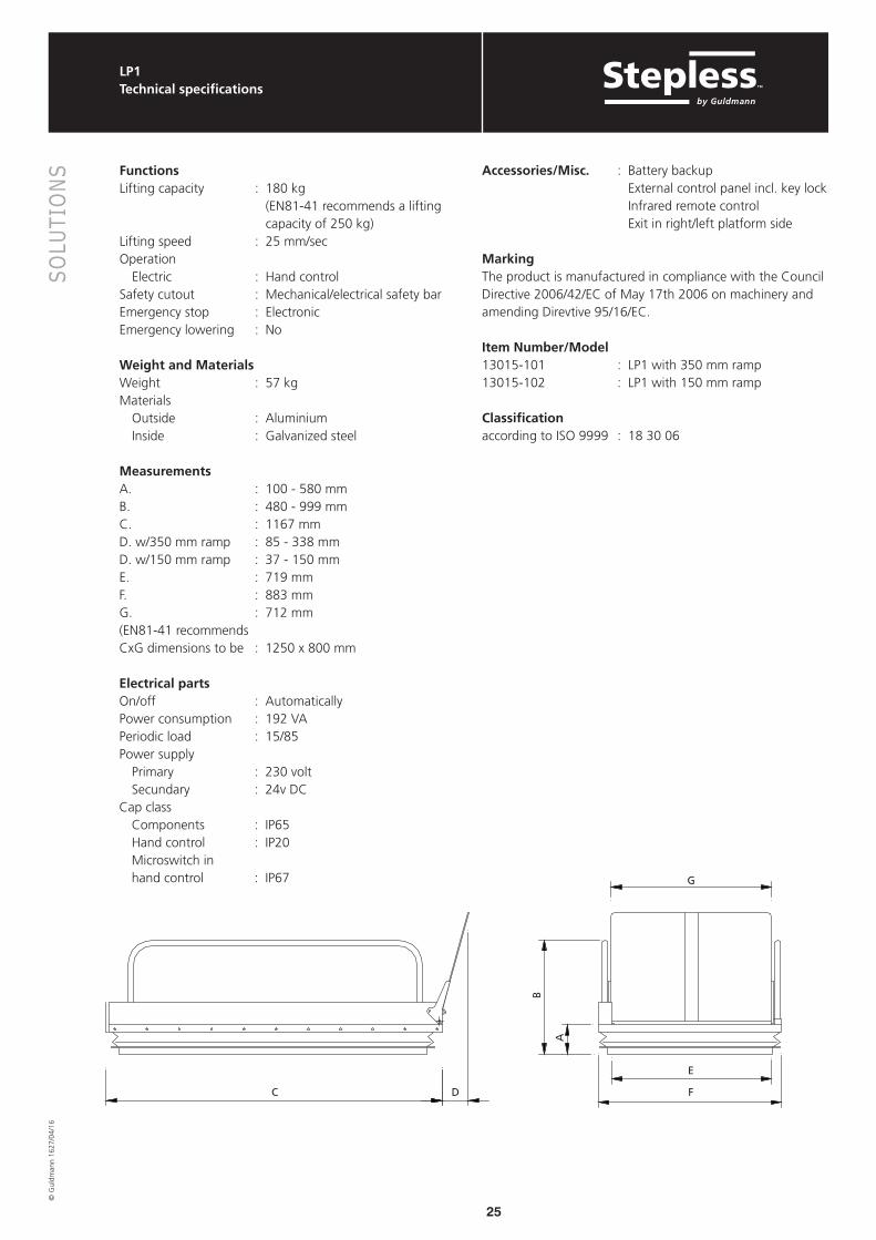
FunctionsLifting capacity : 180 kg
(EN81-41 recommends a lifting capacity of 250 kg)
Lifting speed : 25 mm/secOperation Electric : Hand controlSafety cutout : Mechanical/electrical safety barEmergency stop : ElectronicEmergency lowering : No
Weight and MaterialsWeight : 57 kgMaterials Outside : Aluminium Inside : Galvanized steel
Measurements A. : 100 - 580 mmB. : 480 - 999 mmC. : 1167 mmD. w/350 mm ramp : 85 - 338 mmD. w/150 mm ramp : 37 - 150 mmE. : 719 mmF. : 883 mmG. : 712 mm(EN81-41 recommends CxG dimensions to be : 1250 x 800 mm
Electrical partsOn/off : AutomaticallyPower consumption : 192 VAPeriodic load : 15/85Power supply Primary : 230 volt Secundary : 24v DCCap class Components : IP65 Hand control : IP20 Microswitch in hand control : IP67
Accessories/Misc. : Battery backup External control panel incl. key lock Infrared remote control Exit in right/left platform side
MarkingThe product is manufactured in compliance with the Council Directive 2006/42/EC of May 17th 2006 on machinery and amending Direvtive 95/16/EC.
Item Number/Model13015-101 : LP1 with 350 mm ramp 13015-102 : LP1 with 150 mm ramp
Classificationaccording to ISO 9999 : 18 30 06
C D
B
A
G
E
F
26
SOLU
TIO
NS©
Gul
dman
n 16
27/0
4/16
LP1Installation dimensions
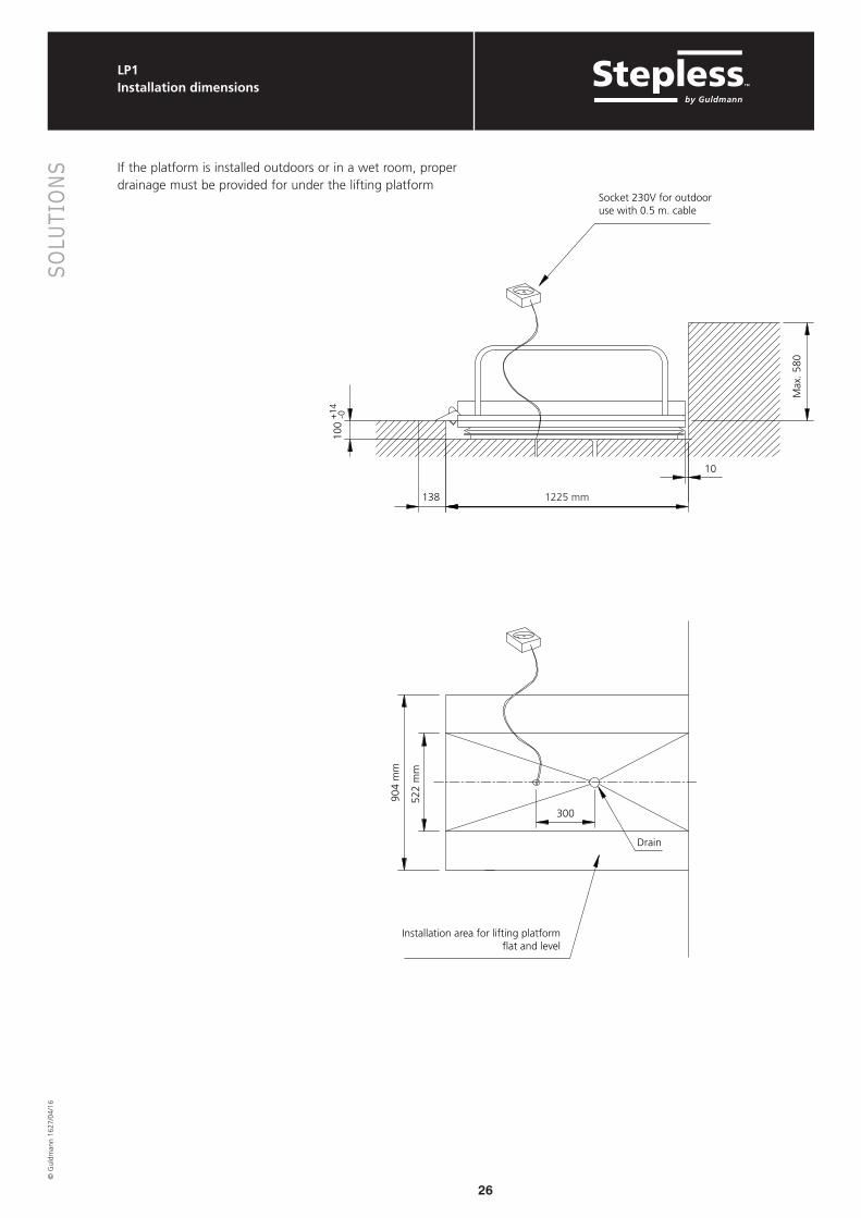
If the platform is installed outdoors or in a wet room, proper drainage must be provided for under the lifting platform
Drain
Socket 230V for outdooruse with 0.5 m. cable
904
mm
1225 mm
10
138
100
Max
. 580
300
+14
-0
Installation area for lifting platformflat and level
522
mm

27
© G
uldm
ann
1627
/04/
16
L P 5
Vertical lifting platform LP5

28
SOLU
TIO
NS©
Gul
dman
n 16
27/0
4/16
LP5Technical specifications
FunctionsLifting capacity : 300 kgLifting speed : 13 mm/sec
Operation Electric : Operating panel Emergency stop : Electronic Emergency lowering : Mechanical Safety lists : Mechanical/electrical safety lists
WeightLP5 : 118 kgSafety gate : 76 kg
MaterialsMaterials : AluminiumMaterials : Powder coated/galvanized steelRailing : AluminiumSafety gate : Powder coated steel and hardened
safety glassCover plate, Safety gate : Electro-galvanized steel plate Electrical partsOn/off : AutomaticallyPower consumption Stand-by : 3 W Operation : 14,7 WPeriodic load : 10/90Fuse : T10ABatteries : 2 x 12V/4.5 Ah Gastight and maintenance-freePower supply Primary : 230 V/115 V Secundary : 24 V DC
Classification, tightnessComponents : IP 65Operating panel : IP 67Safety gateComponents : IP 65
Accessories/ : External control panel Wireless operation
Safety gate Hand control with spiral cable
Exit in right/left platform side
MarkingThe product is manufactured in compliance with the Council Directive 2006/42/EC of May 17th 2006 on machinery and amending Direvtive 95/16/EC.
Item Number/Model13050-101 : LP5, standard13050-102 : LP5, for recessing130590 : Safety gate, fully automatic,
left-hinged (seen from the upper landing)
130595 : Safety gate, fully automatic, right-hinged (seen from the upper landing)
ClassificationAccording to ISO 9999 : 18 30 06
Safety gate
1602 900
1076
790/
150
595
140
- 8
70
120
1100
50
945 1150

29
SOLU
TIO
NS©
Gul
dman
n 16
27/0
4/16
LP5Platform installation / recessing
Platform installationProper drainage must be provided for any outdoor installation of the platform ramp.Never allow the platform to sit in a puddle of water.
The platform’s contact surface must be 100% perpendicular to the vertical wall, or the mounted gate.The base must be firm and stable, e.g. concrete, paving stones, strong timber or asphalt. Sand, gravel or earth CANNOT be used.The platform must not only be supported at different points; there must be support under ALL of the platform’s base frame.Attach the platform to the base through holes in the fittings by the scissors. One fitting to each side of the platform.
Hook up electrical connection of the gate, external service panels and wireless remote control in a connection box under the platform.
Recessing the PlatformIt is possible to recess the platform to provide access without changing levels.If the platform is for recessing, please order it on at special item No.Be aware that when the platform is recessed, the lifting height is reduced by that amount.
Proper drainage must be provided for outdoor recessed installations.
The opening for the recession must be dug in compliance with the illustration.
When the platform is mounted with the gate on the upper level (always with lifting height above 500 mm (20”)), the hole for the down-building must be extended by the thickness of the gate. See dimensioned sketch.
Max
. 870
mm
+20
1640 mm
150 mm
- 014
0
mm
10 mm
1130
mm
500
mm
300
1640 mm
1070 mm

30
SOLU
TIO
NS©
Gul
dman
n 16
27/0
4/16
LP5Platform installation / Built-in dimensions
Platform installationYou can order either a right or left-hinged gate and it will always swing away from the platform. Right/left-hinging can be changed on site if necessary.Mount the gate on the vertical wall, between the platform and upper level. Fixing points in compliance with the dimensioned sketch.Mount pos. 1 on gate so that it is flush with the top edge of the landing. The accompanying board must be mounted to the gate to prevent fingers and feet being crushed between the gate and the platform.Use the accompanying rustproof metal sheet as finish between the landing and the gate.
Hook up electrical connection of the gate, external service panels and wireless remote control in a connection box under the platform.
Built-in dimensionsWhen the lifting platform is mounted between two walls, it is important that the distance between the walls is minimum 1150 mm, as the hinges are wider than the frame of the gate. Min.
1150
437,5437,5
390
1110
320
35
120
50 70
1150
1125
945
Pos. 1

31
© G
uldm
ann
1627
/04/
16
L P 5 +
Vertical lifting platform LP5+

32
SOLU
TIO
NS©
Gul
dman
n 16
27/0
4/16
LP5+Technical specifications
FunctionsLifting capacity : 300 kgLifting speed : 13 mm/sec
Operation Electric : Operating panel Emergency stop : Electronic Emergency lowering : Mechanical Safety lists : Mechanical/electrical safety lists
WeightLP5+ : 150 kgSafety gate : 76 kg
MaterialsMaterials : AluminiumMaterials : Powder coated/galvanized steelRailing : Aluminium and transparent
polycarbonateSafety gate : Powder coated steel and hardened
safety glassCover plate, Safety gate : Electro-galvanized steel plate Electrical partsOn/off : AutomaticallyPower consumption Stand-by : 3 W Operation : 14,7 WPeriodic load : 10/90Fuse : T10ABatteries : 2 x 12V/4.5 Ah Gastight and maintenance-freePower supply Primary : 230 V/115 V Secundary : 24 V DC
Classification, tightnessComponents : IP 65Operating panel : IP 67Safety gateComponents : IP 65
Accessories/ : External control panelMiscellaneous Wireless operation Safety gate Hand control with spiral cable
Exit in right/left platform side
MarkingThe product is manufactured in compliance with the Council Directive 2006/42/EC of May 17th 2006 on machinery and amending Direvtive 95/16/EC.
Item Number/Model13056-101 : LP5+, standard13056-102 : LP5+, for recessing130590 : Safety gate, fully automatic,
left-hinged (seen from the upper landing)
130595 : Safety gate, fully automatic, right-hinged (seen from the upper landing)
ClassificationAccording to ISO 9999 : 18 30 06
Safety gate
110
0
140
- 8
70 1602 1076
900
790/
150
120
1100
50
945 1150

33
SOLU
TIO
NS©
Gul
dman
n 16
27/0
4/16
LP5+Platform installation / recessing
Platform installationProper drainage must be provided for any outdoor installation of the platform ramp.Never allow the platform to sit in a puddle of water.
The platform’s contact surface must be 100% perpendicular to the vertical wall, or the mounted gate.The base must be firm and stable, e.g. concrete, paving stones, strong timber or asphalt. Sand, gravel or earth CANNOT be used.The platform must not only be supported at different points; there must be support under ALL of the platform’s base frame.Attach the platform to the base through holes in the fittings by the scissors. One fitting to each side of the platform.
Hook up electrical connection of the gate, external service panels and wireless remote control in a connection box under the platform.
Recessing the PlatformIt is possible to recess the platform to provide access without changing levels.If the platform is for recessing, please order it on at special item No.Be aware that when the platform is recessed, the lifting height is reduced by that amount.
Proper drainage must be provided for outdoor recessed installations.
The opening for the recession must be dug in compliance with the illustration.
When the platform is mounted with the gate on the upper level (always with lifting height above 500 mm (20”)), the hole for the down-building must be extended by the thickness of the gate. See dimensioned sketch.
+20
- 014
0
mm
150 mm
1700 mm
725
mm
Max
. 870
mm
1130
mm
500
mm
300
1700 mm
1070 mm

34
SOLU
TIO
NS©
Gul
dman
n 16
27/0
4/16
LP5+Platform installation / Built-in dimensions
Platform installationYou can order either a right or left-hinged gate and it will always swing away from the platform. Right/left-hinging can be changed on site if necessary.Mount the gate on the vertical wall, between the platform and upper level. Fixing points in compliance with the dimensioned sketch.Mount pos. 1 on gate so that it is flush with the top edge of the landing. The accompanying board must be mounted to the gate to prevent fingers and feet being crushed between the gate and the platform.Use the accompanying rustproof metal sheet as finish between the landing and the gate.
Hook up electrical connection of the gate, external service panels and wireless remote control in a connection box under the platform.
Built-in dimensionsWhen the lifting platform is mounted between two walls, it is important that the distance between the walls is minimum 1150 mm, as the hinges are wider than the frame of the gate. Min.
1150
437,5437,5
390
1110
320
35
120
50 70
1150
1125
945
Pos. 1
35
© G
uldm
ann
1627
/04/
16
L P 5 0 & L P 5 0 H
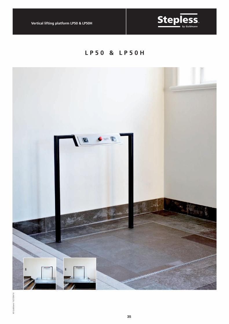
Vertical lifting platform LP50 & LP50H

36
SOLU
TIO
NS©
Gul
dman
n 16
27/0
4/16
LP50 & LP50HTechnical specifications
FunctionsLifting capacity : up to 375 kgLifting speed : 13 mm/sec.
Operation Electric : Operating panel/wireless operation Emergency stop : Electronic Safety cutout : Mechanical/electrical safety cutout
MaterialsMaterials : Aluminium/galvanized steelSafety edge : Anodized aluminium with rubber
stripOperating panel : Powder coated steel. Front
rustproof steel.Platform floor finish : Optional. The weight of the floor
finish will be deducted from the lifting capacity.
Measurements Thickness of floor finish : 22 mmLifting height LP50 : 500 mm Lifting height LP50H : 830 mm. Be aware of local
regulations in relation to lifting height.
Pit depth : 150 mm. Frame for embedment must always be supplied by Guldmann.
Cantilever LP50H : 900 mm
Electrical partsOn/off : AutomaticallyPower consumption Stand-by : 3W Operation : 14.7 WPeriodic load : 10/90Fuse : T10ABatteries : 2 x 12V/7.0 Ah Gas-proof and maintenance-free
Power supply Primary : 230 V/115 V Secundary : 24 V DC
Accessories/Miscellaneous : External operating panel
Wireless operation MarkingThe product is manufactured in compliance with the Council Directive 2006/42/EC of May 17th 2006 on machinery and amending Direvtive 95/16/EC.
Item Number/Model13013-xxx : LP50 vertical lifting platform13012-xxx : LP50H cantilever vertical lifting
platform
Classification According to ISO 9999 : 18 30 06
LP50
LP50H
830

37
© G
uldm
ann
1627
/04/
16
L P 1 1
Vertical lifting platform LP11

38
SOLU
TIO
NS©
Gul
dman
n 16
27/0
4/16
LP11Technical specifications
FunctionsLifting capacity : 300 kgLifting speed : 27-32 mm/secUpper ramp - width adjustable : 630 - 800 mm- length : 1000 mmLower ramp - length : 900 mm
Operation Electric : Operating panel Emergency stop : Electronic Emergency lowering : Electronic Safety lists : Mechanical/electrical safety lists
WeightLP11 : 149 kg
MaterialsPlatform/Ramps : AluminiumBase frame : Steel, powder coatedRailing : Aluminium, powder coated
Electrical partsOn/off : AutomaticallyPower consumption Stand-by : 3 W Operation : 14.7 WPeriodic load : 10/90Fuse : T10ABatteries : 2 x 12V/7.2 Ah Gastight and maintenance-freePower supply & charger Primary : 230 V/115 V Secundary : 24 V DC
Classification, tightnessComponents : IP 65Operating panel : IP 67
Accessories/miscellaneous : Cover for LP11 : Strap for cover
MarkingThe product is manufactured in compliance with the Council Directive 2006/42/EC of May 17th 2006 on machinery and amending Directive 95/16/EC.
Item Number/Model13011 : LP11 - mobile lifting platform
Classificationaccording to ISO 9999 : 18 30 06
850 mm
1140 mm
min
. 120
0 m
m
180
- 100
0 m
m
1400 mm
1630 mm

39
© G
uldm
ann
1627
/04/
16
L P 8
Vertical lifting platform LP8
L P 8
40
SOLU
TIO
NS©
Gul
dman
n 16
27/0
4/16
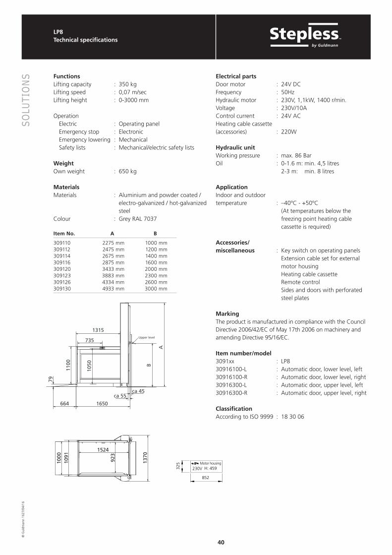
LP8Technical specifications
FunctionsLifting capacity : 350 kgLifting speed : 0,07 m/secLifting height : 0-3000 mm
Operation Electric : Operating panel Emergency stop : Electronic Emergency lowering : Mechanical Safety lists : Mechanical/electric safety lists
WeightOwn weight : 650 kg
MaterialsMaterials : Aluminium and powder coated /
electro-galvanized / hot-galvanized steel
Colour : Grey RAL 7037
Item No. A B
309110 2275 mm 1000 mm309112 2475 mm 1200 mm309114 2675 mm 1400 mm309116 2875 mm 1600 mm309120 3433 mm 2000 mm309123 3883 mm 2300 mm309126 4334 mm 2600 mm309130 4933 mm 3000 mm
Electrical partsDoor motor : 24V DCFrequency : 50HzHydraulic motor : 230V, 1,1kW, 1400 r/min.Voltage : 230V/10AControl current : 24V ACHeating cable cassette (accessories) : 220W
Hydraulic unitWorking pressure : max. 86 BarOil : 0-1.6 m: min. 4,5 litres
2-3 m: min. 8 litres
ApplicationIndoor and outdoortemperature : –40ºC - +50ºC (At temperatures below the
freezing point heating cable cassette is required)
Accessories/miscellaneous : Key switch on operating panels Extension cable set for external
motor housing Heating cable cassette
Remote control Sides and doors with perforated steel plates
MarkingThe product is manufactured in compliance with the Council Directive 2006/42/EC of May 17th 2006 on machinery and amending Directive 95/16/EC.
Item number/model3091xx : LP830916100-L : Automatic door, lower level, left30916100-R : Automatic door, lower level, right30916300-L : Automatic door, upper level, left30916300-R : Automatic door, upper level, right
Classification According to ISO 9999 : 18 30 06
664
Upper level
1100
1315
79
A
B
1650
735
1050
ca 45 ca 55
325
852
Motor housingH: 459230V
1091
923
1524
1370
1000

41
SOLU
TIO
NS©
Gul
dman
n 16
27/0
4/16
LP8Main dimensions
664
Upper level= 173
1100
79
Tow
er h
eigh
ts (A
)
B1650
1050
Lifting height A B
1000 mm 2275 mm 1000 mm
1200 mm 2475 mm 1200 mm
1400 mm 2675 mm 1400 mm
1600 mm 2875 mm 1600 mm
2000 mm 3433 mm 2000 mm
2300 mm 3883 mm 2300 mm
2600 mm 4334 mm 2600 mm
3000 mm 4933 mm 3000 mm
Radius = 1138
Radius = 1065
2690
1524 92
3
1370
1091
1000

42
SOLU
TIO
NS©
Gul
dman
n 16
27/0
4/16
LP8Installation dimensions
325
852
1470
-0
Motor housingH: 459
490 -0
1650 -0
1250
-0
Pit
125
Drain
250
250250
230V
L 1650 x B 1470 mm
79+
5 -0
The external motor housing/engine box can be placed within a radius of 2.5 metres from the point X. Power point outlet 230V should be placed where the external motor housing is planed to be located.

43
SOLU
TIO
NS©
Gul
dman
n 16
27/0
4/16
LP8Installation dimensions
Surfaces less than:1. 400 mm from the platform:
Must constitute an unbroken surface and comprise hard elements (e.g. bricks, raw concrete, wood, or similar).
2. 120 mm from the platform: Must be smooth without irregularities that exceed the limits shown in figure 9 (e.g. plastered concrete wall).
3. 20 mm from the platform: Must be completely smooth (e.g. aluminium panels, glass, smooth wooden panels, or similar).
x = distance to closet structure dependent on the type of finish.
xx
xx
44
SOLU
TIO
NS©
Gul
dman
n 16
27/0
4/16
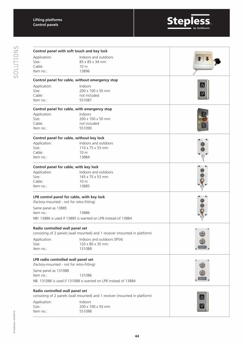
Control panel with soft touch and key lock
Application: Indoors and outdoorsSize: 85 x 85 x 34 mmCable: 10 mItem no.: 13896
Control panel for cable, without emergency stop
Application: IndoorsSize: 200 x 100 x 50 mmCable: not includedItem no.: 551087
Control panel for cable, with emergency stop
Application: IndoorsSize: 200 x 100 x 50 mmCable: not includedItem no.: 551090
Control panel for cable, without key lock
Application: Indoors and outdoorsSize: 110 x 75 x 53 mmCable: 10 mItem no.: 13884
Control panel for cable, with key lock
Application: Indoors and outdoorsSize: 145 x 75 x 53 mmCable: 10 mItem no.: 13885
LP8 control panel for cable, with key lock(factory-mounted - not for retro-fitting)
Same panel as 13885Item no.: 13886
NB! 13886 is used if 13885 is wanted on LP8 instead of 13884
Radio controlled wall panel setconsisting of 2 panels (wall mounted) and 1 receiver (mounted in platform)
Application: Indoors and outdoors (IP54)Size: 120 x 80 x 35 mmItem no.: 131088
LP8 radio controlled wall panel set(factory-mounted - not for retro-fitting)
Same panel as 131088Item no.: 131086
NB. 131086 is used if 131088 is wanted on LP8 instead of 13884
Radio controlled wall panel setconsisting of 2 panels (wall mounted) and 1 receiver (mounted in platform)
Application: IndoorsSize: 200 x 100 x 50 mmItem no.: 551088
Lifting platformsControl panels
45
SOLU
TIO
NS©
Gul
dman
n 16
27/0
4/16
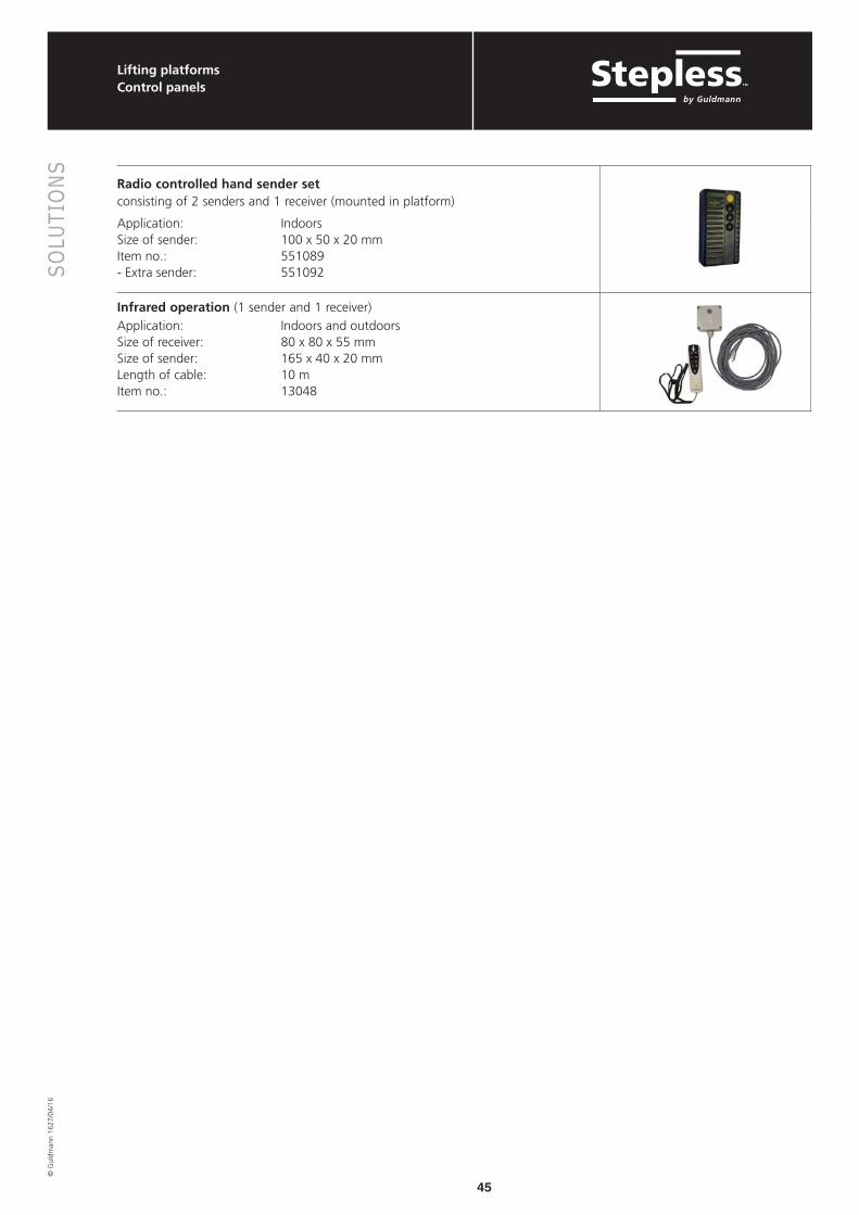
Radio controlled hand sender setconsisting of 2 senders and 1 receiver (mounted in platform)
Application: IndoorsSize of sender: 100 x 50 x 20 mmItem no.: 551089- Extra sender: 551092
Infrared operation (1 sender and 1 receiver)
Application: Indoors and outdoorsSize of receiver: 80 x 80 x 55 mmSize of sender: 165 x 40 x 20 mmLength of cable: 10 mItem no.: 13048
Lifting platformsControl panels
Item no.:

46
SOLU
TIO
NS©
Gul
dman
n 16
27/0
4/16

47
© G
uldm
ann
1627
/04/
16
STAN
DAR
DS
AND
LEG
ISLA
TIO
N STANDARDS AND LEGISLATIONStandards and legislation in connection with negotiating height differences . . . . . . . . . . . . . . . . . . . . 48Building reulations . . . . . . . . . . . . . . . . . . . . . . . . . . . . . 49EN 81-41: Lifting platforms . . . . . . . . . . . . . . . . . . . . . . . 50
48
STAN
DAR
DS
AND
LEG
ISLA
TIO
N©
Gul
dman
n 16
27/0
4/16
Standards and legislation in connection with negotiating height differences
Standards and building regulations are important sources of reference when establishing proper access conditions.A ramp system that is too steep and which does not comply with the building regulations may present a danger to the user. The following is a brief excerpt from the different standards. For more detailed information a Stepless consultant should be contacted or reference made to the complete text of the rules.
Please check your local building code before planning proper access.

49
STAN
DAR
DS
AND
LEG
ISLA
TIO
N©
Gul
dman
n 16
27/0
4/16
It is important to know the local Building CODE when building a stationary ramp system for wheelchair access.
You should therefore obtain and follow the local Building CODE/Disabled Act for your country with specific attention to the following issues:
• Access to public/private buildings• The maximum gradient• The size (lengths/widths) of walkways and platforms• Railing • Landings• Non-skid surface• Stairs/steps
Please note that local building regulations may vary.
Some general recommendation can be given. However, please confirm it with your local Building Code/Disabled Act:
• The maximum gradient 1:20 (ramp approach should not be steeper than 1:12)
Platform outside a door should be
• 150x150 cm • 150x170 cm, here is added 20 cm for
doors that open outwards
• Platform in level with the floor inside
• Intermediate landings should be placed every 10 m
• Minimum width of walkway in public areas
• Rise and depth of the stairs
• Height of railing
Building reulations
18 cm
30 cm
Ca. 90 cm
130 cm
10 m

50
STAN
DAR
DS
AND
LEG
ISLA
TIO
N©
Gul
dman
n 16
27/0
4/16
EN 81-41: Lifting platforms
EN 81-41: Safety rules for the construction and installation of lifts - Special lifts for the transport of persons and goods - Part 41: Vertical lifting platforms intended for use by persons with impaired mobility.
EN 81-41 - Extract:
5.1.5 Rated speed The rated speed of the lifting platform shall not be greater than 0.15 m/s.
5.1.6 Rated load The rated load shall be calculated at not less than 250 kg/m2 of the clear loading area. […]
The maximum permissible rated load shall be 500 kg.
5.1.7 Load controlThe platform shall be fitted with a device to prevent normal starting, excluding re-levelling of hydraulic drives in the event of overload on the platform. The overload is considered to occur when the rated load is exceeded by 75 kg.
In the event of overload: a) users shall be informed be an audible and visible signal
on the platform; b) doors shall remain unlocked or unlockable in the
unlocking zone.
5.1.8 Platform dimensions
5.1.8.1 The clear loading area of the platform including any sensitive edge, photo cell or light curtain, but excluding hand rails, shall not exceed 2 m2.
5.1.8.2 […]
5.1.8.3 In buildings with public access, the platform length shall not be less than 1400 mm, to enable sufficient space for an attendant.
5.4.10.17 Emergency operation
5.4.10.17.1 Moving the platform downwards The lifting platform shall be provided with a manually operated emergency lowering valve allowing the platform, even in case of a power failure, to be lowered to a level where the passengers can leave the platform. The emergency lowering valve is to be positioned outside of the liftway. [...]
5.5.15 Control devices
5.5.15.2 Control devices shall operate as follows:
a) Control devices located on the platform, which are used to control the movement of the platform shall be dependent upon hold-to-run.
b) Control devices located at landings, which are used to control the movement of the platform shall not be hold to run. […].
5.5.16 Emergency alarm devices
5.5.16.1 In order to call for outside assistance, passengers shall have available in the platform an easily recognisable and accessible device for this purpose. This device shall allow a two way voice communication allowing a permanent contact with a rescue service.
Minimum dimensions of platform
Principal useMinimum plan dimensions
(width x length)Minimum rated load Kg
Type A and B wheelchairs with an attendant and adjacent entrances
1100x1400 385
Type A and B wheelchairs with an attendant and adjacent entrances
900 x 1400 315
Lone user, either standing or in a type A wheelchair
800 x 1250 250

51
STAN
DAR
DS
AND
LEG
ISLA
TIO
N©
Gul
dman
n 16
27/0
4/16
EN 81-41: Lifting platforms
5.6 Specific requirements for lifting platforms with enclosed liftways
5.6.1 Top clearanceWhen the lifting platform is in contact with the upper mechanical stop, the vertical clearance between the floor of the platform and the lowest parts of the overload obstacles shall not be less than 2 m.
5.6.3 Enclosure construction
5.6.3.1 Each wall of the enclosure shall form a continuous vertical smooth surface and be composed of hard elements.
5.6.3.2 Any hollows in or projections of enclosure walls shall not exceed 5 mm and projections exceeding 1.5 mm shall be cambered to at least 15° to the vertical (see Figure).
1 1
1,5 mm 1,5-5 mm
15º
Figure 9: Definition of max. permissible rough spots on rendered building elements
Figure – Dimensions of permissible projections for enclosed liftways
5.6.3.4 For lifting platforms with travel up to 3 m the enclosure shall extend to a height of not less than 1.1 m above the floor of the upper landing level. For travel heights over 3 m the enclosure shall extend to a height of not less than 2.0 m above the floor of the upper landing level.
5.6.4 Glass
Glass panels to be used in walls of enclosed liftway or of the platform:
Type of glass Minimum thickness in mm
Diameter of inscribed circle
1000 max. 2000 max.
Toughened and laminated
8(4+4+0.76)
10(5+5+0.76)
Laminated 10(5+5+0.76)
12(6+6+0.76)
Dimensions in millimetres
Glass panels to be used in hinged doors:
Type of glass Minimum thickness
Maximum diameter of
inscribed circle
Toughened 8 100
Toughened and laminated
8(4+4+0.76)
1000
Laminated 10(5+5+0.76)
1000
Dimensions in millimetres
In short:• Max. load 500 kg• Automatic run from the landings• Still hold-to-run from the platform • Travel more than 3 m = no half door

PlanningGuide©
Gul
dman
n
Stepless – Access for allUnder the Stepless brand we sell accessibility– accessibility that gives the walking-impaired,wheelchair users and others on wheels accessto their surroundings.• Portableramps&doorstepramps• Platformlifts• Bespokeplatformlifts
Guldmann – Time to careUnder the Guldmann brand we are engaged primarily in improving the overall working environment within the health care sector, where people need assistance being moved, liftedandpositioned.
Guldmann Consulting – Competence programs Tailor-made educational programs, project courses, topic days, seminars, lectures, analysisandevaluationsfromanergonomicperspective.Ourparticularareaofexpertiseisthe physical working environment surrounding thetransfer,mobilizationandrehabilitationofpeople/patients.
V. Guldmann A/SGrahamBellsVej21-23ADK-8200 AahusNTlf. +4587413100Fax +4587413131E-mail [email protected]
GB