full page fax print - nasa · introduction this flight plan has been prepared by the flight...
TRANSCRIPT

APORO 10
APOLLO AS-505/CSM-106/LM-4
FINAL FLIGHT PLAN
APRIL 17, 1969
Submitted by: Clw...^„^ Z) : 'L,. t,I TT^_E^ FippertJr. -^7TFlight Planning Branch
feyFlight Planning Branch
W. M. AndersonFlight Planning Branch
Approved by:
Chief , Might Crew Support Division
ad-K. S
laytonDirector of Flight Crow Operations
Concurrence:George M.ILOWManager , Apollo Spacecraft Program
rrs op Kraft, r./Director of Flight Operati ns
Any comments or questions on this document should beforwarded to E. B. Pippert or W. M. Anderson , FlightPlanning Branch , mail code CF34 , extension 4271.
TABLE OF CONTENTS
Introducti onAbbrevi ations
SECTION 1 - GENERAL
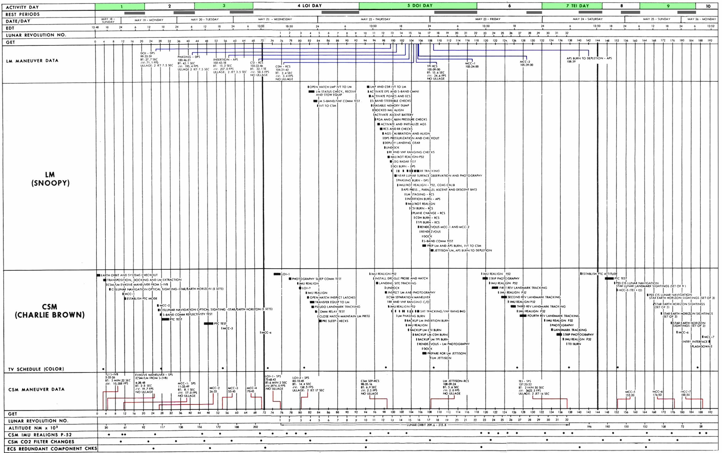
Mission DescriptionSunmary Flight Plan (Fig. 1-1)Rendezvous Profile (Fi g. 1-2)Spacecraft Altitude vs. GET (Fig. 1-3)Bum Schedules (Table 1-1 and 1-2)Lunar Landing Site and Landmar!< Tracking Data (Table 1-3, 1-4)CSM and LM Flight Plan NotesCSM and LM Communications and Instrumentation Notes
SECTION 2 - MANEUVER UPOATE FORMS
Maneuver Update Fonns SunmaryCSM Maneuver Update FormsLM Maneuver Update Forms
SECTION 3 - DETAILED TIMELINE
LaunchS-IVB Orbital OperationsTransl unar Coast Activi ties
Hi dcourse Nav; gat; onLunar Orbit Insert; on
Lunar Orbit Act; vitiesFi rst IngressLM Checkout and ActivationLM Undocking thru UndockingAPS Bum to Depletionlandmark TrackingTransearth Inject; on
Transearth CoastEntry
SECTION 4 - DETAILED TEST OBJECTIVES
Detailed Test ObjectivesMission Activity/Test Objective Cross Reference (Table 4-1)Test Objectives/Mission Activity Cross Reference (Table 4-2)Correlation of Test Objectives with Mission Phases and Activities
SECTION 5 - CONSUMABLES ANALYSIS
SM-RCS SunmaryCSM SPS SunmaryCSM Cryogen; c SUlTlJlary
iiiii
1-11-51-61-71-8, 1-91-101-111-29
2-12-22-24
3-13-33-63-9, 3-183-393-393-433-523-563-663-753-913-913-116
4-14-24-34-8, 4-9
5-15-15-1

LM RCS SummaryLM DPS SummaryLM APS SummaryLM 02 Summary
LM EPS Summary
INTRODUCTION
This Flight Plan has been prepared by the Flight Planning Branch, FlightCrew Support Division, with technical support by TRW Systems.
This document schedules the AS-505/CSM-106/LM-4 operations and crew activitiesto fulfill, when possible, the test objectives defined in the Mission Re-quirements, F Type Mission, Change A, dated April 9, 1969.
The trajectory parameters used in this Flight Plan are for May 18, 1969launch, with a 72° launch azimuth and were supplied by Mission Planning andAnalysis Division as defined by the Apollo Mission F Spacecraft OperationalTrajectory.
The Apollo 10 Flight Plan is under the configuration control of the CrewProcedures Control Board (CPCB). All proposed changes to this documentthat fall in the following categories should be submitted to the CPCB viaa Crew Procedures Change Request:
1. Items that impose additional crew training or impact crew procedures.
2. Items that impact the accomplishment of detailed test objectives.
3. Items that result in a significant RCS or EPS budget change.
4. Items that result in moving major activities to a different activityday in the Flight Plan.
5. Items that require a change to the flight data file.
The Chief, Flight Planning Branch (FCSD) will determine what proposed changesfall in the above categories.
Mr. W. M. Anderson will act as co-ordinator for all proposed changes tothe Apollo 10 Flight Plan.
Any requests for additional copies or changes to the distribution lists ofthis document must be made in writing to Mr. W. J. North, Chief, Flight CrewSupport Division, MSC, Houston, Texas.
ii

I.,' ~~
ABBREVIATIONS
/CaL _QI!~I'''''''''' ~r,' 1...'_. LIl l ... ' .......t.. ' bI< bU.. II/CII IsC"'-tOllo !H.... 50........ I"'" UPII lt~ ""cl... '1"'t1,~ Oil,..,..,.I(T ktt 'III lot CIIli fllll I.Itt""'~IIfIUclIIIl.,. .-U ... t.J' 50\ SIlo" ....,1.~ ~tI"'.. f_ l ........... • 111....'1' m Spoeo<"'"II(A _. 11..I....t<> _I, IJI iEl!I:.......n ••r , .....,.,. IIIlI III<1rtA. "",I. SCI $.."..1 Candlttonll!1 ["Ii1,l1~tIlil _llOut_._,... UI b-,,",,1 OWl "'_1 sa S~t 1t;uUOI'I Contf'Ql SrSl.e!IIAll ............. IN .....t_ SC'T Sc-.i.., T.lel'tClP='AU .'U_ ,
f S'"'
1llI_....... o,...t(;,....s~ lI[C -AI')'.....-".... ~ f.. l cell ICe111__100.
IUO S-l" 1"'11. (ol-off... ...11".... RIM n t"'l Dt _ ....Ult.... '"10''''' o«-tI "''110'. c:.ttol tenter .... ItDwstaa lI[, Sopo...",.. ""'.... Fl.I '11",. 01'" M::C 5(Q 500-.... -- III ~::r.":',,=,,,.tod IDl: lilt. Ot.,I., Cooso'. SIft Sa.... IV 1(1IIt ... Sla90l... .,1I.0J>t••11<••• _ nrr OQS .........t SU Sto-ot .. _1. Ul Moo..'
"/t1!, ~lItof••f St....l .......hUt... 0' SI .. '" ... m ,., pe" MCOIM 11:1 USIlS III......,. 5LOS SUr l t ......,.lllit"t.ID'f 11 _t Dotl<.' '.1_ n.,." foot 11:1 ItIntlllft £vent ttal,. .. ServIa ltadllli'.IPS _lCllllt 'f"OPtIItl.ton SUlbl)'l~ no ,,,11 h""Ul. PoIitt.. IU li..l. 1_1 ...,1. sPG'f Spot .......IllS ~........tttlt,.uOlll ....1 111_1_1.. sPs Son1eo .....,.t.. SilO.An MtI_ Cli Iir.Ift4 ....... Is'....... El'llttinll f"t ...... Ill.
.u..._51 SMrtll'..... ...... '1 ..... - In....._ (lVIl U """"'t. [slM4 a Floriillll SII; ".." ........ COO..t ....
U Ilrt..llo eo; 1l7I'00I..,., c...'" - _..... - w.ocIkot... _ ... IC(IS GIl...... t1'tfln1i1 ~ ::::.:..'1:::I
nt:C'::_1$I Suo...
UI ......, 11:1 _II......". IISfll sn 5-_ I..-tl _ ... IIDl - 11:11 _ 11.,... 11. o'l.,ttl.. IIIIC ......l n.,....l Wf(:t... C.tTOI !iIIC Sel,r Wtfll" ~JIo(It. It_tea' 00......teo _1I11l llU i'ru' SOt swt ...• ..""...,. CIIT _do,..n• 112 1ft....., SIT s......tIT .... I .... IiIII i0oi_ ... "..1,,01'" M, flarigaU.• :=,"',.. CIICS .._ "ri,.lt. C_, s,._ fI:( Corneu_ CdIIiIItl'lt10lIl ....,....r I It• ., I"""""",,,.. - - .. ....'.ul Niltl II'llElla.l'. .....chl CIIl ~••III'CO .... _..,
TA l __t....I.151 _ .., S,....... I• 1.............. I4I4.ItflCin"W' COIl O:-I.e-l..... 112 .,...,.. .. _Ill
11 It._ ...CAL I Collntt.....1. M -...11t".-
lit(01I'M c_. ... _It
:::::ut..leA T100 of C'....I "l>l>rM<hG (Irat. _. - .,'" lit .... (1'\.111 ..s til( t ...."""flt.II.... t.. llJI U ..tt..• Coos.... Otl.. ""_ ... =='LI':'~'"::.:. 01' "tll1_ .. f\ool ""0 m: I .... Eor1ft Coo••- - _...
11M II&A 0..... '''''1'''''0 111 I~ JMI!rtton- till c...U"I Du...to "' III'" ...1 ..1It ..t ...ct ....1 *'t.Mnt till' r",rt.b.lre- (IK c:t..c.larluU. :L "'t.. IIOt ... 0fIS ta;: ...... s,.... '1(. r....' "I"Ql CIlotk .....,.0<11,. (.-.... IoIIt...lI.l (l1li .., To =a,,1.lt, To...01
__10 ..,. _.... --. _I .... Dt."., C.......~ L.... mCIIC ~_Io,,-,". lIlT ... "'t$.i~hl!
..100 Ort_tttt.. fll Tt_II' J..tttllll'lCIlIlT CooU_ - 0........ at fl":lM '-gqr Cout010 - ICDU '....,.101 c..lt...... llolt ,'ttefo
al t .....llA1:r [ftW1'tj CItI- __,.'11.'ID ldnUfl¢ltiClft MIl Ttl.. IIp<Iato 1'\.11 1.1_.....
CIlI. Cootro' ICII l.,tIt. I'Ol "',.. Co<Io _lott... '" till_t,..l ....IN Ftl!llllCIG QIooo:l ... IJII I.rttal ...,.....rU; _it 'C ""'<:7","t.. "I T..... ft,l.l_~" [lIittfn~OIIICOM e- ~t1<a1 111_t Sl,,,, ,"n Ifltti.l1l11tlOlll !'SO _ ............-It TOll T....t... h .....rdelDUtu... e--tcattam. lIT 1_1_10. ..cs .....'101-. ....:.::1 .. COO....1 Stoll.. r/J. r......ttttr/RKl'iqrCOIfIG COO,t,....t. " 1,.$ tit' Pat.t 'I.... - lrtfls1.t101'1CIlIlT cooot_ l~ r.t:r.HUiU.. ""it 1'1.15 ~1:~;:I~1 ~":..IIc<lI"""to. IT '.h'tls1.CP Coot..' ....t llC ~'ttrwflt 0lIl11 t e.-unt.ut1.:!Ii .. __,.tod nc "'....1 fft.... Cool..,(Ill C4rn1..... t -..sl:r..lt. In ••tr'ilwhta.la.. trtfllfe, 'CO- hl.-riltJ or .-ol.lrUt.. TIll 1_aro '"-,< .. ~~ Sooth .".t<.CSI Coom"t< __ lot"..... __ .lin ..-ttt-s_ .., 1M _tll<a'Clll e-.d 'Sth'U tIDIhiIll' PIIfI' ,..,.•••t .. - _ICIIIS ~..c:....";;1:3 SlIt.> .... Itt_It_ "ISS -- us I>ot ... SlaIK , •••til Ollltl "'..".LA 1..... .l.rl...tIo PT ....t , I<loct.,DIIP Dt gl'" ...~ 'tlol LIT Ult_ .... '_tt_l ... USIS 1_'"ilia DI.db.ltkI LIl Loo IU .... (TLlll '" , •.,.011..1 IfttH••u.. VIlf Q')' "I'" f .........,lI:.O. Dt,l'" '-'" ..._1, LIS.,. lb._ Nl5 .......11 ••• UtlH ••U....... Ga,t.. s,..." VU f.1_DIlII\ Do.. l ••". .... D'.. '., lliri ly Lei Ll~.t~ Cool.. ,.,...1 PTC hll.... ~l c.t",l '1 JIMr-t,t.l ""0<:1\,DIIS ~. lOG ......dillllJ "'"
_.IIDl ....,.......1'"DfPI. o.,orolt .. U1'll ......II".. P.. ......... u ... "'.....lEI Ueblf'll't't,Ui., or Dt,l ltl lttelllt Ttr.ler LEI l~rE.j ......tll)'
01" '",- va LIIII'l..r , .... lionJon Ilt7 Q!Mru:tt, If/O ,"_I11I hd: or DlH:tH UlC LJllot_,-to. .-r WU....,..1 to1II1 Oesant OP"'1 t 1ftS,t?'tt II1II LJI L."-..... • ..11/"- IftI WlS ....._W'S Dnaru, """'15tOll "'11~ 'III lacll Hof'tIO.lrl.tl 11M "'1110..OS! 00.. Stor... lout,....t vt:1 L.ft-.... (oot_, la, UO RadtU(II" II'U l'rnt.h'rr.olT
I::~~I~n~=r:-: L1MI 1."'.-_ '-... l ...t_1 .., .tIIt htlD..... ..n frln:.i 1: Of' r.,.~ftSI"f t t......lIlO LHm Loll _ 5t ... S...... too.. l..... •ts Rue Um COIItro I S)'1 t_ -10 ' ...n!t,..,...III! DI,. ..I ..." •• -"_I, Ltllll UUlt ...........t* leU -.ot.@' COII"IU.I iLIII'tlIIIl - LUI ........ lMlttng Hill iil'l It' a~~ft... , ,..
LLOS L_"'U.. 0' 5';11' I!((l US05 ..........1 Erl;!._li1!! LIt I...... NI;Jdw_t IInINi "'fenrtIcf! 5t1bl~ ....." ....ltrh: ., ,"1.<117 Ooao" (Ptfr.....Wllw.rp hf'ly 1.po110 Scito,.Unt ["'1IIi1rt"...~ ..iI......"" lII' L.-.r 'bhl'" P"ilot II~ 1«:1."'''' .we Wo'O<tl,)' C..... " C09'''' C.tofTUS h-l'iP"lDl'o'""Cfltll Cord"'Gl 51Uc-:l L" llllltr :NiH... IIDrl,fOll ICQD fIoqutJ'N III '1DI1tion ~~ (Dl'f@'~till)Ifll hr." iii... dori1_ lOl L......r Of"btt l'lll$trtion .. .,...,.....11 h"Ui1 (..'In;Is~rt'~ lf11l.1' ..f.~ lQIIG l""'ln.... 01' ~dlU$ 01' UJMIt~ Sttt:' &-bllls fliOflit Dtf"H:tor Atli 1...-. II1;Jl(oIt.(Ir lroAJ)a Ihl'Nt.tQj'J LOS t::/';...~c:l';;:i ~1ri'5 ~f S~ t.t' "Ol Ilen4lt.l'l'ltU1oUlIO'. 1o.1loL.-.... L'll OR _".t~'5. R.4t,. I Cs. '(APIS
~~~ r:::~~ron~ LI L....t"'l_. 051 Ran StUUit ... hdtl,.Ul)1DItt LT Lt"'1 " billlllj•.fPc [irtb r.,... h., Or'blt LTG U"'U"I -I< 1iI!'"~I-'I~[,,""1'IdCP~ [1.lCtl"l,"51~rs.,tli ... J'1-"'t'III t, UIII'K:. hfllelof

SECTION 1 - GENERAL

MISSION DESCRIPTION
1. Launch and LP.O. (Duration 2:33) TO - 2:33 GET
(a) Nominal launch time is Sunday, 12:48 EDT, May la. 1969, with a
launch window duration of 4 hrs. 25 min.
(b) Earth orbit insertion into a lOOnm circular orbit at 11 min.
43 sec. after lift~off
(c) CSM systems C/O in earth orbit
(d) IMU 'realign (P52) to the pad REFSMMAT during the first night
period
(e) TlI occurs at 2:33:26 GET over the Pacific Ocean during the
second revolution. (See Table 1-1 for bum data and Figure 1-3
for altitUdes)
2. Translunar Coast (Duration 73:12) 2:33 - 75:45 GET
After 111 which places the spacecraft in a free lunar return trajecto
ry, the fo 11lJili n9 major events occur pri or to lOI:
(a) TV at 3:48 p.m. May 18; 4:03 p.m. May 19; 6:48 p.m. May 20;
1 :08 p.m. May 21 (EDT)
(b) Transpos iti on. docking and LM eject; on ; ncl uct; n9 51 VB photo-
graphy
(c) SIVB separation and a CSM evasive maneuver at 4:28:48 GET
(d) SIV8 propulsive venting of propellants (slingshot)
(e) Two batches of P23 cislunar navigation, star/earth horizon,
consisting of five sets at 05:30 GET and five sets at 25:00
GET
(fj The IMU will be realigned to the PTC REFSMMAT after MeCl
,
(g) Four midcourse corrections which take place at TLI + 9 (SPS) TLI +
24, LOI - 22 and LOI - 5 hours withL>V nominally zero (See Ta-
ble 1-1) for MCC 2, 3, 4
1-1

(h) S-Band reflectivity test with the Ascention SO-ft. cooled antennaat 27:00 GET and at an altitude of l12,OOOnm.
(i) The HGA will be checked for the sleep Comm mode at 32:00 GET
(j) Passive thermal control (PTC) will be conducted at all periodswhen other activities do not require different attitudes
(k) LOI will be performed at 75:45 GET which ends the TLC phase
3. Lunar Orbit (Duration 61:35) 75:45 - 137:20 GET
LOI Day. (Starts at 68:00 GET)
(a) TV at 1:08 p.m. and 9:33 p.m. May 21
(b) LOI-l
(c) Photos of targets of opportunity
(d) LOI-2
(e) Post LOI-2 LM entry and inspection. LM S-Band OMNI andsteerable antenna tests
(f) Post LOI-2 Pseudo landmark tracking(two sets of sightings) (See Table 1-4)
(g) Rest period (8 hours)
DOl Day (Starts at 93:DO GET)
(a) TV at 3:01 p.m. May 22; 1:23 a.m. May 23 (EDT)
(b) Docked LM activation and checkout
(c) Docked Apollo landing site number two sighting (one set of sight-ings) (See Table 1-3)
(d) Undockin9 and separation (See Figure 1-2 Rendezvous Proffle)
(e) Undocked Pre-DOl LM activities
(f) DPS DOl maneuver (See Figure 1-2 and Table 1-2)
(g) DPS phasing maneuver
1-2

(h) LM staging maneuver •
(i) APS insertion maneuver
(j) lM active rendezvous
CSI
PC
CllH
TPI
(k) Docking
(1) Configure LM for APSburn to depletion and perform communi
cati ons tes ts
(m) Unmanned LM APS burn to depletion
(n) Rest period (9 hours)
Landmark Tracking Day (Starts at 118:00 GET)
(a) TV at 7:08 p.m. May 23 (EDT)
(b) Landmark. tracking for four revolutions (four landmarks per rev.)
(See Table 1-4)
(c) One revolution of strip photography
(d) Rest period (3.5 hours)
TEl Day (Starts at 132 :00 GET)
(a) SPS TEl maneuver at 137:20:22 GET
(b) Rest period (5.5 hours)
(c) One revolution of landmark tracking and photography
Lunar Orbit Particulars (Average Values for a 50 x 60nm Orbit)
(a) Revolutions start at 1800 longitude
(b) Revolutioo duration - 1 hr. 58.5 min.
(c) SIC night period duration - 47 min.
(d) MSFN coverage per rev. - 72 mi n.
(e) Orbit inclination _ 1.30
T-3
•
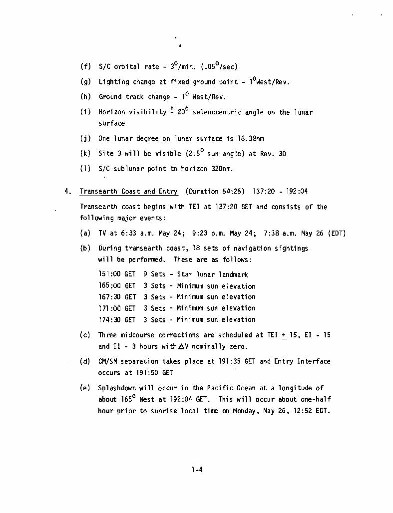
(f) SIC orbital rate - 30/min. (.050/sec)
(9) lighting change at fixed ground point - lOWest/Rev.
(h) Ground track change - ,0 West/Rev.
(n Horizon visibility! 20° selenocentric angle on the lunar
surface
(j) One lunar degree on lunar surface ;s 16.38nrn
(k) Site 3 will be visible (2.5° sun angle) at Rev. 30
(1) SIC sub lunar point to horizon 320nm.
4. Transearth Coast and Entry (Duration 54:25) 137:20 - 192 :04
Transearth coast begins with TEl at 137:20 GET and consists of thefollowing major events:
(a) TV at 6:33 a.m. May 24; 9:23 p.m. May 24; 7:38 a.m. May 26 (EDT)
(b) During transearth coast, 18 sets of navigation s;ghtings
will be perforrred. These are as follows:
151 :00 GET 9 Sets - Star lunar landmark
165:00 GET 3 Sets - Minimum sun elevation
167:3) GET 3 Sets Minimum sun elevation
171 :00 GET 3 Sets Minimum sun elevation174:30 GET 3 Sets Minimum sun elevation
(c) Three midcourse corrections are scheduled at TEl!. 15, EI . 15
and EI - 3 hours with~V nominally zero.
(d) CM/SM separation takes place at 191 :35 GET and Entry Interface
occurs at 191:50 GET
(e) Splashdown will occur in the Pacific Ocean at a longi~ude ofabout 165° west at 192:04 GET. This will occur about one-half
hour prior to sunrise local time on Monday, May 26, 12:52 EDT.
1-4

"
'-- ---;.)-4. ---------:------------- ~ "1~u_
~
MINl-fOOTlAll1,2 - (SEE DETAil)
lNAL PHASEe, 9, 10Th~DETAILl
""
"-""\
'\\:-~,,,••
NTIN./IlJ ),~'~OIS'tAC!ME ,TRAILING 250
". ,
..~
us TIlAJECTORY"F" MiSSiON RE~~;~~~INEAIl CO-ORO.)(CSM CENTERED
END:
-NIGHT
_ -- DAYlIGHT
.n...'" ...'"9llo3S:16
NO.
CSM SE'ARAlION~"....,
I 100;"":11,
~lsINGIURN,
, ~
t~,,~l:~'~"L-__~:~'~N~I~-~.:OO~'~..~I:~~----,..7--~·--;-"'''.o_____=::~~O:...::'A~':':M'~N'~-'N~-.M-'f_J----2~----2 '~,'!.... -'"O~ 'UIION' ",..110 l-I----.(1 10
,
'HA$I!lUMINAL

]
200
I' ,'1
1: :j, , ..
" ,",IIi :~:
,,',":",.. ,1::', ., ,
190
""i:J:
:It:;= -;:!...• ,_, -'t
180
.;::::..;! -f.... ,.. ,,,,:::", t-,
;.'1
170
" 1-+4 -ll'r+.,-I I .
-IT 'if ;:1:
I.· i:t :-;c~.~ ;:-';+-'-' ~', -~ .. _- .
160
i
150140
i: . '~-!it:l' U'Fi' j':
++--c- " -, •• j"
'.1:
..::t -•.- .-,~ '-'- +
;:~~ h;:' ,.t :~-iFij. I-Nl;:l:~:i y:t:j-prf j
~ ~2 -~~;. -~l;W~.*~ ~-~~~ <it ~!h_~:f.,
iT.: '
,... ,
'fll"jiinli' [I'! IFi ill 111 ' ~TEI ,"
iii i'hlll,:Ci HI L1i '111[il11' 'jl
"
LUNAR ORBIT 209.6 - 215.8 Ki: ~:t,~n~- :, r:
80 90 100 110 120 130
GROUND ELAPSED TIME iG.E. T.)
,..
-,+
7060
- ~+,,-, .:::: ;,
t~ t'+1 :J=~
+; r;.-' .;' t-
50403020
'e~.
{'~~C;I'
10
\:It; wIt _ ,.1
:q=:. '-ttt'-,!Fe:
oo
180
140
x::< 120Z
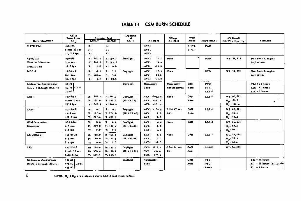
TABLE 1-1 CSM BURN SCHEDULE
GETl LlrbainrBun. Tm.. Aititu" .. ., Ullar" 'vc l>V Ru"lt
Bu.."fM...eu""r .V ~'LV taartial GETl IJ.V llpo' 4V (fpal ..... REYSMMAT (SC wi., Up' "AI Rem....k ••s_lve TLl Z,33,Zl> R. R, 4VX, S·IVB p~
5 mla 2Z _ee p, p, 4VY, I. U.
10,05811'0' y, y. ll.VZ,
=Ie>< 4:28048 R, lSO. I RI180.7 DaylilJht l>VX: ,. , N_ .p~ WT, 94.513 Un B"lIl< A enri"..
Evuive Ma"""""r Z.8 'ee p, nZ.6 p, 163.3 6.VY, 0.0 wll val.....
from S-IVB 19.7 tpa y, O•• y, 0.0 ll.VZ, -19.0
MeC·j 11,33>10' R, U R, U Daylipt 4VX, --fz. 9 N=. .,C WT, 94, 392 Un Bank B onsine
8. t a"e p, •42.6 p, ,., 'VY. ,.. ban valve•
51.0 ipa y, ,.," 10.5 ll.VZ, -36.0
MidcDUr.e Corrections ,",,,I Oayll,ht Non>Ulally Nou>t.....ly ~N .,C T L:I + 24 houn
(MeC _2. Ihrough MeC.oj,) 53,,,"5 GETI Zero Not Required ~~ .,C LOt - ZZ "OIln
70,45 LU-' LOI • 5 b""n
LOI-! 15,45'43 R, 356.5 R,3S6.3 Dayli,ht 4VX, -2912. ') N=. ~N CU·, WT:9Z•.u7
6 ...... 2 ..'" 16Z.8 P,Z32.0 "(SS - 8,11) "'VY, -587.5 A.~ lip: 59.6 -p, .2.974 fps " 345.6 Y, 340. 5 4VZ, -201,0 "A' 170.6
LOI-Z 80,10,45 R, O•• R, O. , Daylight AVX, -138.5 Z Jet 17 ..ee EON LLS-Z WT,68.Ut
t4.4 lee p, I8z.4 P,2zt.O (SR + 20:45j AVY, 0.0 AV, Auto Hp ,59.6
UB.5 fp. y, 357.6 y, 357. 6 AVZ, 0.0 N ,60.2
CSM separation 9i,35,16 R, 0.0 R, 0.0 Dayllpt AVX: 0.0 N_. ~N LU-' WT,36.4B4
Maneu,,",r 6.9 ,,"e p, 269. B p, 194.2 (SS _ 14:44) AVY, 0.0 tip,59.2
2.5fpl y, 0.0 y, 0.0 AVZ, ., H ,60.1
LM 3etti.."" IOB:09:Z4 R, 180.0 a, lBO.O Do,_ AVX, 0.0 N_ ~N LLS-2 WT,36.674
5.6 lee p, 89.9 p, 70.3 (58 _ 32.,36) AVY, 0.0 tip,59.3
2.0 fpl Yo 0.0 y, 0.0 AVZ, ·.0 N ,60.0
"" 137,20,22 R, 179.9 a, IBO.O D&yll.tl:ht AVX, 3618. I 2 Jet 14 lee ~ LU-' WT,36.575
2 miD 50 lee p, HO.' p, ,.. (Sa + U:zz) AVY, -H.8 AV, A.~
3622.5 fpa Yo 359.9 Y, 359. 8 AVZ, 1176.4
Mtd<:ou.... Correetl",," t5Z:Z01 Dayli,ht Nomi....lly ""H .,C TEl + 15 hou...
(MCC_5 through MCC_7J 176,50 CiETI Zero Auto .,C E< - 15 hou... El191'5°1IB8,50 Entry E, _ 3 hout.
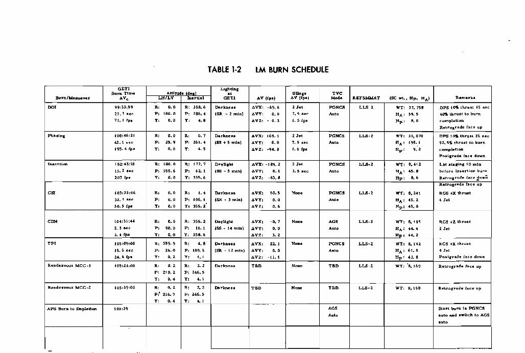
TABLE 1-2 LM BURN SCHEDULE
GETI LillhtUllBurn Time Attitude " ., Ullage TYC
Burn/MuJue""r ". utia GETl 4V (ipe' 4V (ipe) ..... REFSMMAT (SC ..t., Mp. HA' Remuka
DO< 99:33;~9 R, ,., R, 358.6 DArkneu ll.VX: _69.6 2 Jet PONeS w , WT: 37.758 DPS t~ thr"ot 15 •••27.1uc p, 180.0 p, 286... I~ ~ 2 min) 4VY: ,. , 1.5 .ec ~'o HA: 59. 5 ."'" thruet to burn71. 1 lpo y, ,. , y, ••• .Il.VZ: . ,. , t. 5 ip. tip: ••• completion
Retrograde face up
Pllulng 100:46:21 R, ,. , R, ,. , Darkn.... 4VX: 169. I 2 Jet PONCS LLS-Z WT: 31,070 DPS l()fo tlln,,"' 26 oec
oil. I .ec p, 25.9 p, 261. " (SS + 5 min) ll.V¥; ,. , 7.5 no AulD HA
, 195. I 92. Sf, thruat to burn
195.4 fpo Y ,. , y, .. , .:l.VZ: -94.8 t.6 ip. Hp : '-' <omplett""
Po.igrede face dovm
lnaertion 102:43:18 R, 180.0 " 171.7 DayUgbt 4VX, 189.2 2 Jel PaNCS LLS_Z WT, 8.412 LM staging 10 ml"
15.2 UC p, 155.6 p, 62. I lSS - 5 min) iJ.VY: ,. , J.5 ne Auto HA' 45.8 before Inaert'.,.. hurn
207 IV- y, ,. , y 355.6 6VZ, _83.8 Hp' .. Retrograd.. f"e~ 20"';'lI... ,rograd.. tau up
C~ 103:33:46 R, ,. , "' ... Dark>l~.. Il.VX: 50.5 N~ ~=, LLS_Z WT, 8, Z41 RCS +x thrlUlt
3Z. I ue p, ,. , p, 106.1 ($ - 3 min) 4VY, ,. , Amo "A: 45. Z 4 J ..t
50.5 fPf' y, ,. ,"' 355. Z 4VZ: ,..
Hp ' 45.0
C~ 104,31:44 R, ,. , R, 355. Z Daylight Il.VXt .., N~ AO' LLS_Z WT, 8.195 RCS +z thruOi
Z.3 sec p, 90.0 p, 16. I (SS _ 14 min) Il.VY, ,. , Amo "A: 44.4 Z Jet3.4 Ips y, ,., y, 358.6 Il.VZ: ,. , H , 44. Z
TP> 105:09:00 R, 359.9 R, ••• Dar""... Il.VX: ,,- , N_. PGNCS LLS-Z WT: 8.19Z RCS +x thruot
15.6 lee p, Z6.0 p, 189.5 (sa -12mln) 4VY: ,. ,~'" "A: 61.8 4 Jet
24.6 fps y, ,., y, ,., Il.VZ: ·11. 1 Up: 43.8 Pooigrade face down
Rendezvouo MCC_l 105:24:00 R, '-' R, U Darkness TBD N_ TBD LLS-2 WT, 8.169 Retrograde lace upp, 210.2 p, 246.5
"' ,.. "' .. ,RendesvouB MCC_2 105:39:00 R, ,. , R, '-, Dar""e .. TBD N~ TBD LLS-2 WT: 8,158 Retrog?ade lace up
P:' 216.7 p, 246.5
"' ,.. "' .,APS Bu.... to Depletion 108:39 AO' Start bu ..... in PGNCS
Auto auto ...d ...itch to ACS
auto
- -----

TABLE 1-3 • LUNAR LANDING SITE DATA
(For Gene..1 Infonnation Dnly)
DAY
~AY 18
~AY 20
~AY 23
~AY 24
~AY 25
SITE DESIG.
2(I1 P6)
3(1 I P8)
4(III P11)
5(I1 P13)
5(1I P13)
LAT
0044'N
0022'N
3039'S
10 46'N'~o46IN
LDNG
230 39'E,oZl'W
360 42'W
41 056'W
41 056'W
SUN ELEVATION ANGLES·mOL. AZ. ) (J080L AZ. )
11.4° 14.3°
10.9° 13.7°
10.3° 12.9°
17.0° 19.0°
28.0° 30.0°
*Sun El angles are for approximately 25 hours after LOI
TABLE 1-4 LANDMARK TRACKING DATA
~ITE DESIG. LAT LONG SUN EL GET (TCA)
REV. 4
IP (Fl) ,°171 N 93°50' E 71° 82:32
FI 1036'N 86oS3'E 64° 82:34
IP(BI ) 1°30' N 40006'E 18° 82:49
B1 2°31' N 3So02 l E 13° 82 :51
REV. 11
IP(130) ,oS3 I N 28044'E 13° 96:40
130 1°16 ,N 23041'E 8° 96:42
EV. 24, 25, 26, 27**
IP1OOOIN 178°26' E 4° 121 :28
CPIOOS3'N 170°09' E 12° 121 :30
IP20048'N 132029'E 50° 121 :42
CP2 100'N. 127024'E 55° 121:44
IP(Fl) ,o17'N 93°50 'E 89° 121 :54
Fl 1036'N 86oS3'E 84° 121 :56
IP (130) 1053'N 28044'E 26° 122: 16
130 ,o16'N .23041'E 21° 122:18REV 30
IP(Bl) 1°30' N 40°06' E 44° 134:02
B1 2031'N 35002'E 39° 134:04
IP(l50) 0018'N 3°23' E 7° 134:14150 0017'N 1026'W 2.6° 134:15
··Sun E1. and GET for REV 24 only
1-10
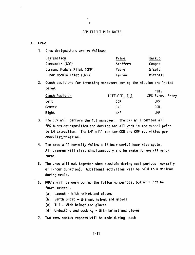
CSM FLIGHT PLAN NOTES
A. Crew
1. Crew designations are as follows:
Designation
Commander (CDR)Command Module Pilot (CMP)Lunar Module Pilot (LMP)
PrimeStafford
Young
Cernan
Backup
CooperEisele
Mitchell
2. Couch positions for thrusting maneuvers during the mission are listedbelow:
TO&ECouch Position LIFT-OFF, TLI SPS Burns. Entry
Left CDR CMPCenter CMP CDRRight LMP LMP
3. The CDR will perform the TLI maneuver. The eMP will perform allSPS burns,transposition and docking and all work in the tunnel priorto LM extraction. The LMP will monitor CDR and eM? activities perchecklist/timeline.
4. The crew will normally follow a 15-hour work.9-hour rest cycle.All crewmen will sleep simultaneously and be awake during all majorburns.
5. The crew will eat together when possible during meal periods (normallyof l-hour duration). Additional activities will be held to a minimumduring meals.
6. PGA's will be worn during the following periods, but will not be"hard suited".(a) Launch - With helmet and Qloves(b) Earth Orbit - Without helmet and gloves(cj TLI - With helmet and gloves(dj Undocking and docking - With helmet and gloves
7. Two crew status reports will be made during each
1-11
activity day. The first report will be given after the first mealof the day and will concern the sleep obtained during the previoussleep period. The second report will be given following the finalmeal of the day and will concern the radiation dose received duringthe previous 24 hours. The following information should be transmitted or logged as appropriate:(a) A daily report of each crewman's best estimate as to sleep
quantity and quality(b) A daily report of the integrated radiation dose each crewman
receives(c) An onboard record of food not eaten and exercise (no voice
report required)(d) Used fecal bags will be marked as to crewman and GET(e) A daily report of all medication used by each crewman
8. General flight plan updates containing changes to the schedulednext day's activities will be voiced up once a day.
9. Negative reporting will be used in reporting completion of eachchecklist.
10. No CSM biomedical switching is required. Continuous biomedicaldata are automatically transmitted to the ground Simultaneouslyfor all crewmen.
11. Crewmen will sleep simultaneously. Two crewmen will normally bein the sleep stations under the couches and one in the couch.During the LOI Day sleep period. two crewmen will be in thecouches because the probe and drogue will be stored in one of thesleep stations.
12. One crewman will wear headsets at all times during the mission.
13. All onboard gage readings will be read directly from the gagesand will not be corrected by the appropriate calibration factors.
14. Periodic spacecraft systems monitoring is a continuing task andis not scheduled in the flight plan timeline.
B. Maneuvers
1. CSM/LM and CSM attitude maneuvers will normally be at a rate of
1-12
O.Zo/sec. or O.So/sec. unless other rates are required to supportmission objectives or time critical events.
Note: At 0.20/sec. 15 minutes is required tomaneuver 1800 • At O.So/sec, 6 minutesis required to maneuver 1800
.
2. Passive thermal control mode will be initiated after MCCl and maintained throughout the mission (except in lunar orbit) until atleast three hours before entry except for interruptions for midcourse corrections, communications orientation, and/or performanceof mission objectives (maximum interruption of three hours). PTCwill not be initiated until approximately TLI + 12 hours.
3. In order to conserve SM RCS, the SPS engine will be used to IIbackUpll all LM burns. The SPS gimbal motors will not be turned onduring the lIback-up" maneuver preparation.
4. The fi rst SPS burn wi 11 be on engi ne valves BANK !lA" and the secondburn will be on BANK uB".
5. The CSM will perform the final docking maneuver after the LMactive re~dezvous.
6. The crew will manually back up all critical engine starts andcut-offs.
C. Electrical Power System and Water Management
1. Spacecraft lift-off switch positions are listed in the ApolloOperations Handbook (Volume 2) for CSM 106.
2. The spacecraft will remain fully powered up throughout the mission(CMC, IMU and SCS in the lloperate ll configuration and" optics poweredup as required).
1-13
•
3. Fuel cell HZ and 0z purging will be scheduled as follows:
02 purge - each lZ hours
HZ purge - each 48 hours
This schedule may change in real time depending on the purity of
the Oz and HZ. HZ purge line heaters are activated ZO minutes be
fore an HZ purge.
4. Hydrogen VAC ION pumps will be inactive throughout the mission.
The fuses will be pulled.
5. The O2 VAC ION PUMP MAIN A/MAIN B CB (2) (PANEL NO. 229) will be
open for launch and will be closed at 85% - 90% QT'1 (before pressure
about the VAC ION pump increases si gni fi cantly).
6. Potable water will be chlorinated before each sleep period start
ing at the first sleep period.
7. No FC purges or waste water dumps will be scheduled within one hour
prior to optical sightings.
8. Waste HZO dumping will be managed to allow:
(a) Maximum QTY: 85-90%
(b) Minimum QTY:25%
(c) At LOI :QTY = 75%
(d) At CM-SM SEP:QTY = 90%
(eJ No dumping after MCC-4 until after LOI
(f) Dumps will be perfonned (if required) within 2 hours preced
ing MCC maneuvers.
(g) In lunar orbit if dUlllling is required, du~s will be perfonn
ed ilTl1'ediately prior to sleep periods.
(h) The water dUmp will not be operated in the automatic mode at
anytime during the mission.
1-14
9. The cryogenic heaters will betin AUTO during the mission and the
fans will be operated manually. The fans will be cycled for one
minute before and after each sleep cycle.
10. The batteries will be charged after TLI. LOl 2 and TEl. The tenta
tive charging schedule is as follows:
Battery A - GET 2:45 {interrupted for evasive maneuver}
Battery B - GET 22 :00
Battery A - GET 87: 30
Battery B - GET 118:00
Battery A - GET 146 :00
Battery B - GET 164:30
11. Inverter No.1 and 2 will be used during the mission even though the
C & Wtemperature light for inverter number one is inoperative. In
verter No.3 will be used as the backup inverter.
D. Environmental Control System and Cabin Pressurization
1. One CO2 odor absorber filter (LiOH canister) is changed every 12
hours or. if CO 2 partial pressure is greater than 7.6rrm Hg. There are
20 filters (2 in the canisters onboard and 18 stowed).
2. An Ecs recij.mdant component check is perforrred at 24-hour intervals
(in order to prevent secondary evaporator dry out) and prior to TLI,
Lor (4 to 10 hours before), and entry (2 to 10 hours before).
3. The ECS redundant component checks will inc1 ude secondary evaporator
operation and the secondary evaporator water control valves wi 11 be
turned "OFF" at deactivation.
4. The evaporator operation will be as follows:
{a} Launch -primary loop operation
(b) Earth Orbit - primary loop operation and secondary loop test
plus redundant operation test
(c) Post TLl - deactivate both evaporators
(d) LOI Minus 2 Hours - activate primary evaporator
(e) Post TEl - deacti ve primary evaporator
(0 Entry Interface Minus 1.5 hours - activate primary evaporator
(9) Secondary evaporator may be activated (EI - 1 hour) at crew
option for cold soak.
1-15
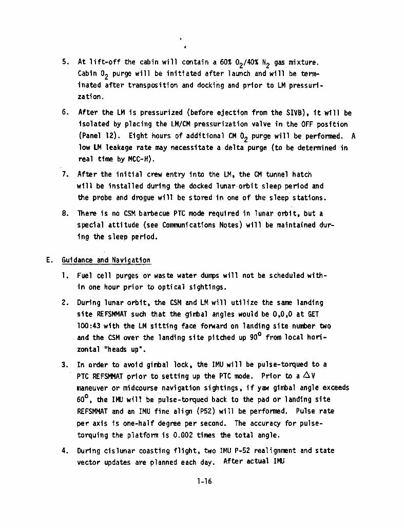
5. At lift-off the cabin will contain a 60% OZ/4O% NZ gas mixture.
Cabin Oz purge will be initiated after launch and will be term
inated after transposition and docking and prior to LM pressuri
zation.
6. After the LM is pressurized (before ejection from the SIV8). it will be
isolated by placing the LM/CM pressurization valve in the OFF position(Panel lZ). Eight hours of additional CM O2 purge will be performed. A
low LM leakage rate may necessitate a delta purge (to be determined inreal time by MCC-H).
7. After the initial crew entry into the LM. the CM tunnel hatch
will be installed during the docked lunar orbit sleep period and
the probe and drogue will be stored in one of the sleep stations.
8. There 1s no CSM barbecue PTe mode required in lunar orbit, but aspecial attitude (see Communications Notes) will be maintained during the sleep period.
E. Guidance and Navigation
1. Fuel cell purges or waste water dulTJ,)s will not be scheduled within one hour prior to optical sightings.
2. During lunar orbit. the CSM and LM will utilize the same landing
site REFSMMAT such that the gimbal angles would be 0.0.0 at GET
100:43 with the LM sitting face forward on landing site number twoand the CSM over the landing site pitched up gOO from local hori
zontal "heads up".
3. In order to avoid gimbal lock. the IMU will be pulse-torqued to a
PTC REFSMMAT prior to setting up the PTC mode. Prior to a f!.vmaneuver or midcourse navigation sightings. if ylJiI gimal angle exceeds
600• the IMU will be pulse-torqued back to the pad or landing site
REFSMMAT and an IMU fine align (P52) will be performed. Pulse rate
per axis is one-half degree per second. The accuracy for pulse
torquing the platform is 0.002 times the total angle.
4. During cislunar coasting flight. two IMU P-52 realigmrent and statevector updates are planned each day. After actual If4J
1-16
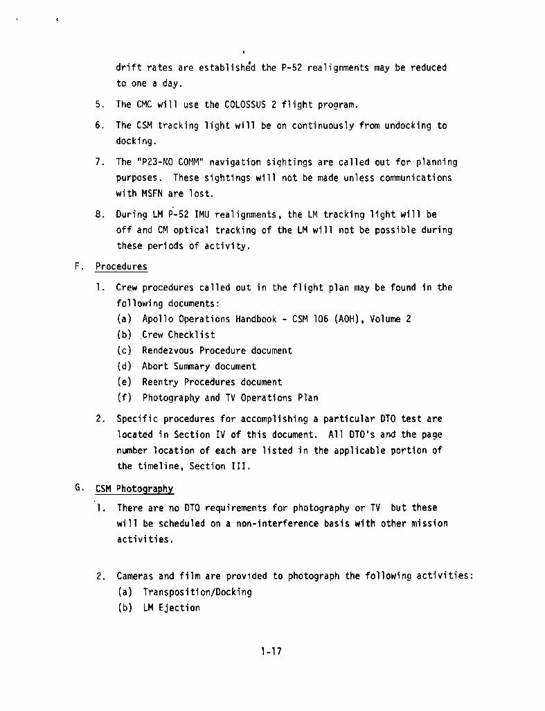
drift rates are established the P-52 realignments may be reduced
to one a day.
5. The CMC will use the COLOSSUS 2 flight program.
6. The CSM tracking light will be on continuously from undocking to
docking.
7. The "P23-NO COMM" navigation sightings are called out for planning
purposes. These sightings will not be made unless communications
with MSFN are lost.
8. During LM P-52 IMU realignments , the LM tracking light will be
off and CM optical tracking of the LM will not be possible during
these periods of activity.
F. Procedures
1. Crew procedures called out in the flight plan may be found in the
following documents:
(a) Apollo Operations Handbook - CSM 106 (AOH), Volume 2
(b) Crew Checklist
(c)
(d)
(e)
(f)
Rendezvous Procedure document
Abort Summary document
Reentry Procedures document
Photography and TV Operations lan
2. Specific procedures for accomplishing a particular DTO test are
located in Section IV of this document. All DTO's and the page
number location of each are listed in the applicable portion of
the timeline, Section III.
G. CSM Photography
1. There are no DTO requirements for photography or TV but these
will be scheduled on a non-interference basis with other mission
activities.
2. Cameras and film are provided to photograph the following activities:
(a) Transposition/Docking
(b) LM Ejection
1-17

(d) SLA/LM/SIVB
(e) Earth Photography
(f) Lunar Surface Targets
(g) IVT (CDR)
(h) LM Undocking and Inspection
(1) Rendezvous (to within 300 ft. of CSM)
(k) IVA Photography - CM Activities
Folding, Unfolding Couch
Stowing equipment on Aft Bulkhead
Donning/Doffing Space Suits
H. The schedule for TV transmissions to earth is as follows:
T&D - 3:00 to 3:15
TLC-1 - 27:15 to 27:30
TLC-2 - 54:00 to 54;15
PRE LOI-1 - 72:20 to 72:35
POST LOI-2 - 80:45 tc 81:55
UNDOCKING - 98:13 to 98:23
APS BURN TO DEPLETION - 108:35 to 108:50
AFTER 3RD LANDMARK TRACKING - 126:20 - 127:00
POST TEI - 137:45 to 138:00
TEC - 152:35 to 152:45
TEC - 186:50 to 187:05
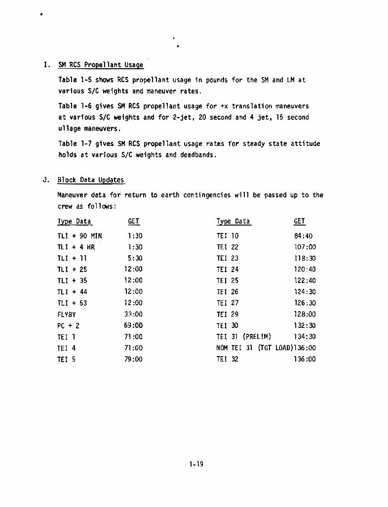
I. SM RCS Propellant Usage
Table 1-5 shows RCS propellant usage in pounds for the SM and LM at
various S/C weights and maneuver rates.
Table 1-6 gives SM RCS propellant usage for +x translation maneuvers
at various S/C weights and for 2-jet, 20 second and 4 jet, 15 second
ullage maneuvers.
Table 1-7 gives SM RCS propellant usage rates for steady state attitude
holds at various S/C weights and deadbands.
J. Block Data Updates
Maneuver data for return to earth contingencies will be passed up to the
crew as follows:
Type Data GET Type Data GET
TLI + 90 MIN 1:30 TEI 10 84:40
TLI + 4 HR 1:30 TEI 22 107:00
TLI + 11 5:30 TEI 23 118:30
TLI + 25 12:00 TEI 24 120:40
TLI + 35 12:00 TEI 25 122:40
TLI + 44 12:00 TEI 26 124:30
TLI + 53 12:00 TEI 27 126:30
FLYBY 33:00 TEI 29 128:00
PC + 2 69:00 TEI 30 132:30
TEI 1 71:00 TEI 31 (PRELIM) 134:30
TEI 4 71:00 NOM TEI 31 (TGT LOAD)136:00
TEI 5 79:00 TEI 32 136:00
1-19

TABLE 1-5 RCS PROPELLANT USAGE - LBS/MANEUVER
SPACECRAFT MANEUVERS
CSM (GNCS)
1-AXIS (180°) 3-AXIS (180 °)S/C WT
0.2°/SEC 0.5°/SEC 0 .2°/SEC 0.5°/SEC IN LBS
2.2 lbs 5.6 lbs 3 .2 lbs 7.7 lbs 94,000
1.7 lbs 4.5 lbs 2 .5 lbs 6.0 lbs 70,000
1.0 lbs 2.5 lbs 1 .5 lbs 3.4 lbs 47,600
0.3 lbs 0.9 lbs 0 .75 lbs 1.3 lbs 38,000
0.3 lbs 0.75 lbs 0 .7 lbs 1.2 lbs 28,600
LM (AGS)
0.5°/SEC 2°/SEC 0 .5°/SEC 2°/SEC
0.4 lbs 1.3 lbs 0 .8 lbs 2.6 lbs 31,000
0.2 lbs 0.75 lbs 0. 4 lbs 1.5 lbs 8,400
.2 lbs 0 . 7 lbs 0 . 4 lbs 1.4 lbs 8,000
TABLE 1-6 CSM G&N RCS TRANSLATION
20 SEC, 2 JET ULLAGE 14.0 lbs N/A
15 SEC, 4 JET ULLAGE 19.4 lbs N/A
I FPS +X TRANSLATION 10.7 lbs 94,000
1 FPS +X TRANSLATION 8.0 lbs 70,000
1 FPS +X TRANSLATION 4.3 lbs 38,000
1 FPS +X TRANSLATION 3.3 lbs 28,600
1-20
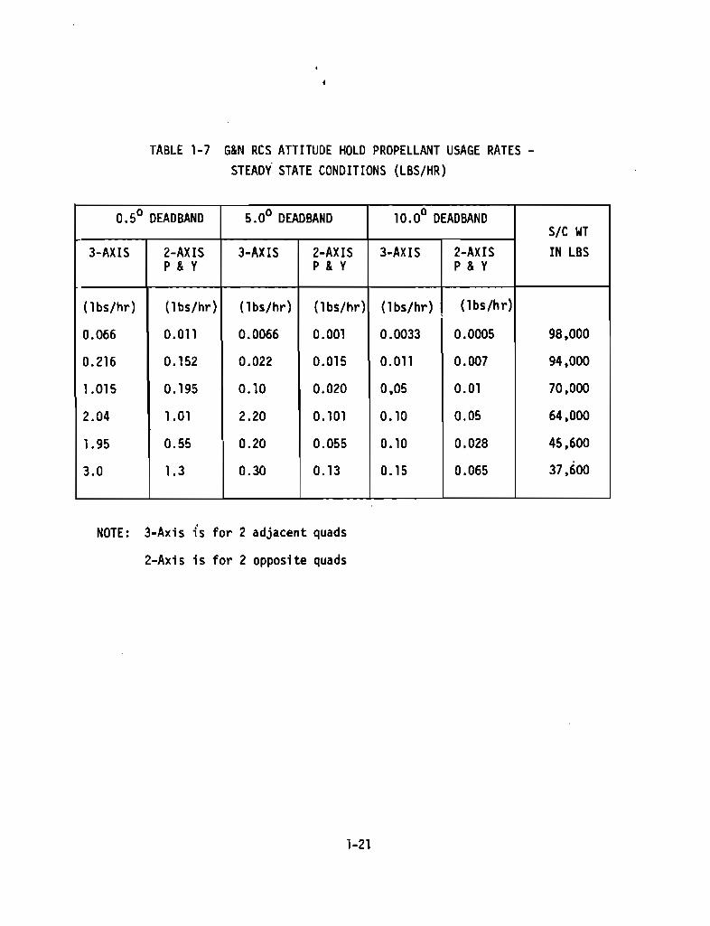
TABLE 1-7 G&N RCS ATTITUDE HOLD PROPELLANT USAGE RATES -
STEADY STATE CONDITIONS (LBS/HR)
0.5° DEADBAND 5.00 DEADBAND 10.0 0 DEADBANDS/C WT
3-AXIS 2-AXIS 3-AXIS 2-AXIS 3-AXIS 2-AXIS IN LBSP&Y P&Y P&Y
(lbs/hr) ( lbs/hr ) ( lbs/hr ) ( lbs/hr ) ( lbs/hr ) ( lbs/hr)
0.066 0.011 0 . 0066 0 . 001 0.0033 0 . 0005 98,000
0.216 0 . 152 0.022 0 . 015 0.011 0.007 94,000
1.015 0.195 0 . 10 0.020 0,05 0.01 70,000
2.04 1.01 2 . 20 0.101 0 . 10 0.05 64,000
1.95 0.55 0.20 0.055 0.10 0 . 028 45,600
3.0 1.3 0 . 30 0.13 0.15 0 . 065 37,600
NOTE : 3-Axis is for 2 adjacent quads
2-Axis is for 2 opposite quads
LUNAR MODULE FLIGHT PLAN NOTES
A. LM Crew
1. The LM inspection and housekeeping activities will be performed
by the LMP in flight coveralls.
2. The LMP will initiate the final LM activation and checkout in
coveralls. The CDR will enter the LM in his PGA (without donning
helmet and gloves). The LMP will return to the CM and don his PGA
(without helmet and gloves). The LMP and CDR will don helmets and
gloves and perform a PGA/ARS pressure integrity check just prior
to the LM cabin regulator check.
3. It should not be necessary to change the primary LM LiOH cannister
during the LM manned operations.
4. One PLSS and two OPS will be carried in the LM. The PLSS will not
be checked out or used during the nominal mission. The OPS's will
be checked out during the housekeeping activities on LOI day.
5. The CM transfer umbilical will not be used during LM activation
and checkout.
6. The LM crew will be suited (without helmet and gloves) during most
of the undocked portion of the mission. For undocking and staging
the LM crew will be fully suited.
7. The LM switch settings at the initial entry will be as specified
in the LM AOH,Volume 2.
B. LM Guidance and Navigation
1. The LGC will use the LUMINARY-69 flight program.
2. The LM AGS will use Flight Program 5 (Mission G will use Flight
Program "X"). Flight Program 5 will not have the RR filter which
increases the range for RR data update to AGS. The AGS RR update
range will be limited to 100nm.
1-22
3. One LGC erasable memory dump and ,~1CC-H verification will be
accomplished prior to DOL If a significant nurmer of errors
are found, 001 will be delayed to allow for memory correction
and re-verification.
4. All maneuvers during the undocked manned lM operati ons will be
under PGNCS control except for the LM staging maneuver and the LM
CDH maneuver (if required). These two maneuvers will be under AGS
control.
5. The capability for ~1CC-H to update the lGC via uplink will normal
ly be blocked by the LM UP-DATA LINK switch (panel 11).
6. A LM CGAS star sighting will be used during the 001 maneuver to
check IMU drift rates. The star should be within 20 of the initial
COAS position prior to the maneuver. The AOT will not be used for
this purpose. The lunar horizon will not be visible during the 001
maneuver.
7. A LM COAS accuracy check will be perforrred after the IMU alignrrent
prior to staging.
8. The Apollo 10 Mission timeline will not include the time required
for all PADS that are required on the Apollo 11 mission for LUNAR
surface aborts or insertion maneuvers.
9. The LM IMU will be manually aligned to the CSM IMU during the 001
day LM activation and checkoYt. P-52/AOT alignments will be per
for~d as soon as possible prior to:
001
Phasing
Insertion
There will be no "back-to-back" PGNCS/AOT alignments performed dur
ing the mission which are not interrupted by a DPS, APS or RCS thrust
i ng maneuver.
10. AGS alignments to the IMU will not be performed when IMU gimbal
angles are at 00 or multiples of 450.
1-13

11. In order to UPLINK data, TLM should be in HBR in order to
facilitate MCC-H verification of LM receipt of the data via
LM-TLM.
12. The time from rendezvous TPI to the rendezvous MCC-1 is 15 minutes
and the time from rendezvous MCC·l to rendezvous MCC-2 is 15
minutes.
13. In order to perfonn AGS initialization, the LM TLM must be in HBR
in order to obtain state vector data from the LM-TLM downlink.
AGS initialization is perforrred prior to each engine bum.
C. lM RCS Operation and Interface Constraints
1. LM RCS "+X" two jet ullage (System B) will be used for unstaged
ullage maneuvers in order to prevent asymrretrical RCS thrust caus
ed by impingement on the descent stage.
2. During CSM/LM docked checkout operations. the SM B3(-x) and C4
(~x) thrusters will be deactivated before the LM steerable and/
or RR antennas have been unstowed in order to prevent SM-RCS
impingement on these antennas.
3. The RCS interconnect will be used during the APS insertion maneu
ver and several of the rendezvous maneuvers in order to conserve
LM RCS propellant. The interconnect can only be used for +x
translations.
4. The maximum +x continuous RCS firing time is 55 seconds on LM-4
(85 seconds on LM-6). For multiple pulse fi rings approximately
one minute of "off" time for cooling offsets approximately one
second of previous "on" time. (See the Spacecraft Operational
Data Book for specifics).
D. LM APS Bum to Dep,letion
1. Prior to LM jettison the CSM will be in narrow deadband attitude
control and the LM will be in wide deadband control (CSM control ling CSM/LM attitudes.)
1-24

2. LM jettison will occur at 90 degrees east longitude approximately
30 minutes prior to the APS burn.
3. The LM S-Band steerable antenna will be set at a fixed position dur-
ing the APS burn and DATA will be in the HBR position.
4. The APS burn to depletion will place the ascent stage in orbit around
the sun.
5. The PGNCS (under MCC-H RTC) will control the start of the ullage maneu-
ver and RTC will be used to switch to AGS control for the remainder of
the ullage maneuver and the APS start and bum.
6. Both RCS interconnects will be closed during the unmanned APS burn to
depletion.
7. The probe and drogue will be stored in the LM during the APS burn to
depletion.
8. The APS will be approximately 50% propellant loaded at the start of
the burn in order to ensure adequate backup RCS propellant to stabi-
lize the LM during and after the burn.
9. MSFN will attempt to track the LM and obtain TLM data after the APS
burn to depletion.
E. Pasive Thermal Control Maneuvers
1. There is no requirement to perform any LM passive thermal control maneu-
vers during lunar orbit.
2. There will be no telemetry or crew monitoring of LM temperatures (or
any other LM data ) between LM pre-launch checkout and the post LOI-2
LM entry and inspection.
F. Rendezvous Radar
1. The turn-on and turn-off times for the rendezvous radar will be scheduled
in such a manner as to prevent overheating of the rendezvous radar an-
tenna.
2. Accurate RR range and range rate telemetry data will not be obtain-
able on the lunar farside because a HBR TLM capability is not
available. This situation prevents MSFN from analyzing the
1-25
operation of the RR system on the lunar farside via DSE data
playback. LM RR LGC state vector updates will be checked
against MSFN computed state vectors after each AOS.
3. Rendezvous radar lock will be broken just prior to TPI in
order to make a +x axis TPI burn. (This is different from the
Apollo 11 Mission).
4. The RR shaft and trunion angles will be at zero during each
AGS RR update.
G. Rendezvous
1. The LM tracking light will be on continuously between separation
and docking except during PGNCS/AOT P-52 realignments.
H. LM Pressurization
1. The LM cabin will contain N2 and some ambient air at launch and
will bleed down to a pressure of zero psi during the launch insertion
maneuver. The LM will be pressurized after transposition and
docking and will then be isolated before ejection and allowed
to bleed down.
I. LM Procedures
Crew procedures called out in the flight plan may be found in the
following documents:
(a) Apollo Operations Handbook LM-4 (AOH) Volume 2
(b) Crew Checklist
(c) LM Rendezvous Procedures Document
(d) Abort Summary Document
(e) Photography and TV Operations Plan
J. Photography
There are no photographic DTO requirements, but cameras and film
will be carried aboard the LM to photograph the following:
(a) Lunar surface strip over landing site
(b) Braking/formation flying
(c) Photos of CSM from LM after rendezvous
1-26
K. lM Activation and Checkout Notes
Activities will be performed during the periods as shown below:
1. Post LOI-2lMP IVT to lM and verify CSM to lM roll calibration anglelM entry status checkTransfer required crew equipment and housekeepingTransfer to lM power and comm activationS-Band/VHF B comm testOMNI and Steerable Antenna voice/TM TestslM and MSFN relay TestsComm deactivation and transfer to CSM powerlMP IVT to CSM and close lM hatch
2. Docked Pre-DOlIVT to lM and verify CSM/lM roll calibration angle
Transfer to lM power and EPS Activation, S-Band TlM-lBR on OMNIActivate Mission TimerBackup S-Band comm activation and comm checkPrimary glycol loop activationCaution and Warning system checkoutPGNCS turn on and self testCircuit breaker activation and talkback verificationECS activation and checkoutSuit Fan/H20 Separator checkGlycol pump checks (1, 2. and secondary)S-Band Steerable Antenna checksVHF activation and checkout
LGC/CMC Clock Sync and TEPHEM updateE Memory dumplM docked manual IMU coarse alignInstall drogue and close lM hatchAscent batteries activation and checkoutARS/PGA pressure integrity checkRegulator checks
1-27
AGS activation and self testRate Gyro check and docked manual fine align IMULM IMU Drift checkAGS initializationORDEAL initializationDAP data load, gimbal drive and throttle testsRCS pressurizationReS checkout (cold and hot fire)Rendezvous Radar activation and self testAGS accelerometer and gyro calibrationUpdate and align AGS to PGNCSDPS pressurization and checkoutLanding gear deploy
3. Undocked Pre-DOl
LM inspection by CSM and formation flyingRendezvous Radar/VHF ranging checkIMU AOT realign (P52)System checksLanding radar testAlign and update AGS
4. Undocked Prior to APS Insertion BurnIMU Realign/COAS calibrationParallel ascent and descent batteriesLM stagingPressurize and check the APS
1-28
csr1 & LM COMMUNICATiONS AND INSTRUMENTATION NOTES
A. CSM/LM Notes - All Mission Phases
1. Table 1-8 is a matrix that shows how the CSM and LM communicationswill be utilized throughout the mission. The matrix consolidatesall communications requirements specified in the Detailed Test Ob
jectives and the Operational Procedures (AOH Volume 2). This
matrix shows the following:
(a) The mission phase or event where each uplink. downlink,antenna, transceiver, power amplifier and data recorder
is exercised
(b) All communications modes used for the lunar earth side
(MSFN coverage) and the lunar fars; de (no MSFN coverage)
(c) Which S-Band antenna (omn;. CSM high gain, LM steerable)
;s used for each uplink or downlink signal corJbination.
(d) Which uplink signal combinations are exercised for CSM
and which uplink signal combinations are exercised for
tM LM
2. The MSFN as-ft. antennas wi 11 normally be used for all lunar dis
tance cormnunication. The Goldstone 2l0-ft. antenna may not be
available for the Apollo 10 Mission. The "uncooled" 3D-ft. MSFN
antennas may be used for CSM lunar distance simulation communi
cations tests at approximately 70Knm. The "cooled" 3D-ft. MSFN
antennas may be used at approximately 110Knm for CSM lunar distance
simulation conrnunications tests.
3. LM to CSM VHF TLM data cannot be transmitted and received during
VHF ranging periods.
4. During communications, the spacecraft will be referred to by narre
(Apollo 10) and MCC-H will be referred to as "Houston". Code:
names assigned to the CSM and LM durinq undocked operations are:
CSM - Charlie Brown
LM - Snoopy
1-29
5. Voice silence (120 seconds) will be required during the CSM PRN
ranging code acquisition sequence when the downlink signal combi
nation is in mode 8 (TLM-LBR and Back-up Voice).
6. The preferred S-Band communications mode for CSM and lM is:
(a) Uplink Mode 6 (Voice, PRN and Updata)
(b) Downlink flode 2 (Voice, PRN, TLM-HBR)
7. It is desirable to have the spacecraft TLM in HBR for all MSFN CSM
or LM computer updates (via the uplink) in order to facilitate ~lCC-H
verification of the updata receipt.
B. CSM/LM Notes - Lunar Orbi t Phase
1. All CSM and LM HBR data at lunar distance will normally require the
use of the high gain or steerable antennas with 85-ft. MSFN antennas.
HBR can also be obtained by MSFN 3D-ft. "cooled ll antennas.
2. After each ADS in lunar orbit, it is desirable for MSFN to use PRN
as much as possible.
3. During lunar orbit, the CSM and LM S-Band systems will not be shut down
on the lunar farside.
4. The lM steerable antenna and the CSM HGA will not be in view of MSFN
during any CSM tracking of a landing site while the vehicles are dock
ed. TLM-LBR and OMNI antennas will be used during this activity.
5. VHF Ranging/Data Switching will be in accordance with the rendezvous
procedure. Voice silence between vehicles should be maintained for
approximately 10 seconds whi le acqui ring VHF ranging.
6. VHF A Simplex is normally used for all VHF Voice Corrmunications ex
cept during VHF ranging when VHF Duplex is used.
7. MCC-H will not nonnally switch S-Band antennas. This activity will
be a crew action except during crew sleep period.
1-30
C. CSM Notes - Launch and Earth Parking Orbit
1. OMNI B and VHF LEFT will be selected for launch. OMNI 0 wi 11 be
selected by the crew during boost phase if the launch azimuth is
less than 96°. OMNI C will be selected if the launch azimuth 1s
greater than 96 0• Of>fllI 0 will probably be the best antenna for
use during earth orbi t.
2. VHF Duplex B will be used for launch and VHF Simplex Awill be
used for earth orbit operations (switch over at CYI LOS). VHF
Simplex "A" will be used during entry in order to be compatible
wi th the recovery forces.
3. CSM FM Modes are normally used for DSE playbacks and TV. HGA will
be required for FM mode operation after TLI.
4. CSM S-Band backup communication modes checks will not be made.
The LM corrmunication system will be used as the backup communi
cation system, if necessary.
5. All CSM communications checkouts and tests may be performed during
translunar coast (post TD&E to pre-LOI). The lunar sleep comm
mO,de will be checked in lunar orbit prior to the first sleep period
6. The CM cOllTl1unications system switches will be configured to permit
MCC-H real time control of routine cOllTl1unications switching and max
imum crew control of the communications without the crew having to
use CMD RESET.
7. The CMC updata link input will normally be blocked by the crew UP
TLM ACCEPT/BLOCK switch. This will not prevent MCC-H from using
real ti me command to cant ro1 the corrmuni cati ons sys tern.
8. The CSM S-Band system will normally be configured as follows unless
preflight tests show that the seconoilry systems wuuld have higher
galn:
(a) Pnmary trilnsponder - ON
(b) Primary Power Amplifier - HI
1-31

9. The trans 1unar and t ransearth sleep cOl11l1uni cati ons mode wi 11 be as
follows:
The CSM x-axis will be placed nonnal to the ecliptic plane.
The CSM wi 11 be placed in GNCS ~ 200 pitch and yaw attitude
hold. All four SM RCS quads will be used with the roll chan
nel disabled. The CSM will be rolled at a rat,e of approxi
mately one revolution per hour. During the near earth sleep
periods (range less than approximately 120Knm) onTIi antennas
Band 0 may be used. During the other sleep periods (beyond
approximately 120Knm) the high gain antenna may be used in the
auto REACQ mode (oane1 2). The auto REACQ configuration will
provide almost 210 degrees of HGA coverage per CSM/LM revo
lution or 35 minutes of MSFN coverage per hour (for a CSM s,pin
rate of one revolution per hour). The auto REACQ configuration
will also allow MCC-H to use real time control to select TLM
HBR or LBR and to dump the DSE during each spacecraft revolution.
The auto REACQ sleep mode will be tested before the second trans
lunar coast sleep period.
10. The communications mode for the lunar orbit sleep period will be as
follows:
The CSM will be referenced to the landing site nunber two REFSMMAT
and will be in an attitude which will place two RCS quads toward the
sun and two RCS quads toward the lunar surface.
The CSM will be placed in an attitude which will allow the HGA to be
used.
The CSM will be placed in a GNCS 3-axis + 100 inertial hold mocle
using two adjacent quads.
1-32

The HGA will be in the auto REACQ mode ( panel 2). The S-Band
squelch will be enabled. The S-Band system will be controlled
by RTC at HCC- H and will be in TLM-HBR on the lunar earthside
and LBR/DSE recording on the lunar farside. This procedure
will provide approximately 75 minutes of HBR for each lunar orbit
and will permit MCC-H real time control of the DSE and playback
of LBR data recorded on the lunar farside . This communications
mode will be tested for suitability just prior to the lunar or-
bit sleep period.
11. During translunar and transearth coast crew-awake PTC periods, the
crew will use manual antenna switching to maintain continuous
communications with MSFN via OMNI and /or HGA. The S-Band squelch
will be disabled to allow the crew to use the upvoice discrimi-
nator noise as a cue to indicate when to switch to another antenna.
12. In lunar orbit the crew will acquire MSFN using the CSM high gain
antenna for each ADS unless specified differently in the flight
plan timeline.
13. A small portable voice recorder will be carried in the CM to be
used at the discretion of the crew.
14. CSM-TV may be scheduled in real time if the Goldstone 85-ft. antenna
is in view of the spacecraft . CSM-TV via the Madrid 85-ft. antenna
should be scheduled approximately 15 hours in advance in order to
reserve communications satellite time.
1-33
D. LM Notes
1. LM voice recorder has a maximum utilization of 10 hours. This
recorder will be used during LM operations to record all LM
voice data during undocked operations (8.5 hours). The record-
er will be operated in the continuous mode (not VOX).
2. As many LM communications special tests as possible will be per-
formed between docking and LM jettison.
3. During "undocked" operation several LM communications test ob-
jectives will be performed as part of the normal mission communi-
cations procedures.
4. The LM S-Band System will normally be configured as follows un-
less preflight tests show that the secondary systems would have
higher gains:
(a) Primary transponder - ON
(b) Primary Power Amplifier - ON
5. In lunar orbit MSFN will acquire the LM steerable antenna for each
AOS unless specified differently in the flight plan timeline.
6. LM TLM will be switched to LBR at each LOS and to HBR at AOS by
the LMP unless specified otherwise in the flight plan timeline.
7. LM Bio-Med switching will be checked out for the CDR and the LMP
during LM checkout and will be switched from one crew member to
the other approximately every two hours after LM undocking.
1-34

8. There will be no TV transmissions from the LM.
E. CSM DSE Notes
The CSM DSE is used as follows:
1. The DSE will normally be operated via ground command. In special
cases the crew may be asked to operate the DSE.
2. DSE will be operated HBR during the launch phase. These data
will be dumped if real time launch data are lost.
3. During the earth orbit period when the CSM is not over a MSFN
station, CSM TLM-LBR data will be recorded on the DSE and will
be dumped durino the pass over the US and over CR0 (if possible)
just prior to TLI.
4. The DSE will be used for CSM HBR and voice recording during all
CSM engine burns and during the accomplishment of certain specified
DTO's.
5. DSE recordings will be made in CSM LBR mode whenever possible in
order to minimize the DSE dump time.
6. All critical data will be hand recorded by the crew when not in
voice contact with MSFN. DSE voice recording will be used as
backup for recording critical data.
7. During translunar and transearth PTC simultaneous sleep
periods using the HGA auto REACQ communications mode, the DSE
will be used to record LBR data when the HGA is not in the MSFN
field of view.
8. During lunar orbit LM operations, the DSE will be used to record
LM-TLM-LBR data during all LM phases/events that occur on the
lunar farside (unless VHF ranging is required).
1-35
9. During lunar orbit. time (in the attitude hold control mode) willbe provided in the flight time1ine to allow for MCC-H DSE dump.rewind and start of DSE after each MSFN AOS (acquisition ofsignal). except where a DSE dump would interfere with DSE recording of critical CSM backup TLM data or the HGA is not visibleto MSFN.
10. LM data will normally be dumped first after each AOS during lMactive operations.
11. Twenty-five minutes will normally be allowed for the completedata dump cycle for CSM and LM LBR data recorded on the lunarfarside. HBR data will require additional dump time dependingon the length of the recording.
12. DSE will be used to record all entry data in HBR during theblackout region.
13. In lunar orbit at LOS, the crew will initiate UP TLM CMO RESET(momentarily) then NORMAL (panel 3) if the OSE motion is notnoted. This situation will occur if MSFN does not get the DSEstarted before LOS.
F. Normal Lunar CSM Comm Configuration
S-BD XPNDR - PRIMS-BD PWR AMPL - PRIMS-BD PWR AMPL HI-HIS-BD MODE VOICE - VOICES-BD MODE PCM - PCMS-BD RNG - RNGS-BD AUX TAPE - ON VOICE BuS-BD AUX TV - OFF (CTR)UP TLM DATA - DATAUP TLM CMD - NORMVHF AM A -OFF
1-36
VHF AM B - OFFVHF AM B RCV ONLY - OFFVHF RNG - OFFVHF ANT - SM RIGHTTAPE RCDR PCM - PCM/ANLGTAPE RCOR RCD - RCD
TAPE RCDR FWD - FWDPMP PWR - NORMSCE - POWER - NOHMPCM BIT HATE - LOW
S-BD SQUELCH - OFF
HI rAIN oNT PWR - PWR
HI GAIN ANT TRACK - MAN
HI GAIN ANT BEAM - WIDE
HI GAIN ANT SERVO -PRIM
UP TLM SWITCHES (MDC 2 - BLOCK & PNL 122 - ACCEPT)
SECTION 2 - MANEUVER UPDATE FORMS

MANEUVER UPDATE FORMS SUMMARY
This section contains samples of the update pads which are contained
in the In Flight Data File on board the spacecraft. The CSM forms
are as follows:
1. TLI Maneuver
2. P37 Block Data
3. P27 Update
4. P30 Maneuver( External AV)
5. Entry
6. Earth Orbit Entry Update
7. Earth Orbit Block Data
8. CSM Sep
9. CSM Rescue
10. CSM Backup Insertion
11. P76 (DOI, Phasing, Insertion)
12. CSM Rendezvous Rescue (CSI, CDH, TPI)
The LM forms are:
1. P27 Update
2. AGS State Vector Update
3. P30 LM Maneuver
4. P32 CSI Update
5. P33 CDH Update
6. P34 TPI Update
7. P76 (DOI, Phasing , Insertion)
In addition, definitions of abbreviations used on the forms are presented
on facing pages.
2-1
CSM
MANEUVER
UPDATE FORMS
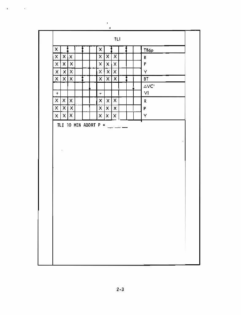
TLI
X X TB6p
X X X X X X R
X X X X X X P
X X X X X X Y
X X X X X X BT
ovcI
+ + VI
7 7 7
7 7 7
X X X
TLI 10 MIN
X
X
X
ABORT P =
X
X
X
X
X
X
R
P
U Y
2-3
TLI PAD
TB 6p X : XX:XX ( HRS:MIN:SEC)
R XXX (DEG)P XXX (DEG)Y XXX (DEG)
BT XX : XX (MIN:SEC)
AVC' XXXXX . X (fps)
VI +XXXXX (fps)
R SEP XXX (DEG)P SEP XXX (DEG)Y SEP XXX (DEG)
P XXX (DEC)
PREDICTED TIME OF BEGINNING OFS-IVB RESTART PREPARATION FORTLI (TB6 = TLI IGN -9 MIN)
PREDICTED SPACECRAFT IMUGIMBAL ANGLES AT TLIIGNITION
DURATION OF TLI BURN
NOMINAL TLI AV SET INTOEMS AV COUNTER
NOMINAL INERTIAL VELOCITYDISPLAYED ON DSKY AT TLICUTOFF
PREDICTED SPACECRAFT IMUGIMBAL ANGLES AT COMPLETIONOF S-IVB MIVR TO CSM/S-IVBSEP ATTITUDE
PITCH ANGLE FOR TLI + 10 MIN ABORT
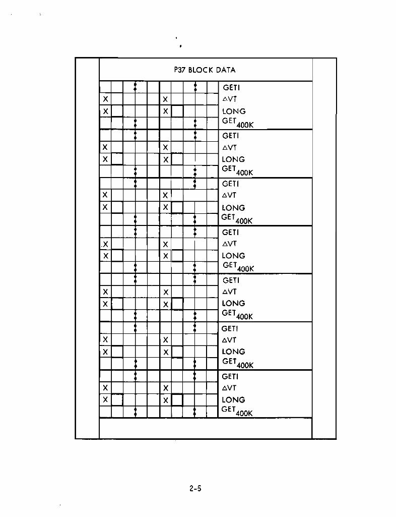
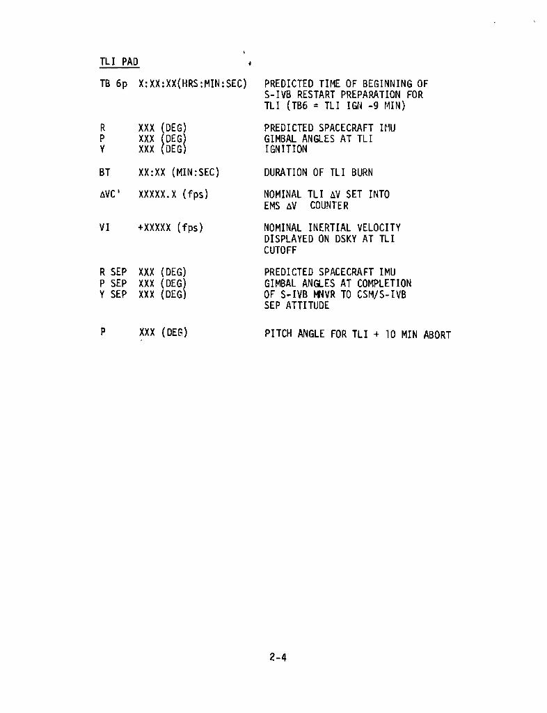
P37 BLOCK DATA
GETI
X x WT
X X LONG
GET400KGETI
X X oVTX X LONG
GET400K
GETIX X oVT
X X LONG
GET400K
GETIX X tVT
X X LONG
GET400K
GETI
X X oVT
X x LONG
GET400K
GETIX X oVT
X X LONG
GET400K
GETIX X oVT
X X LONG
GET400K
2-5
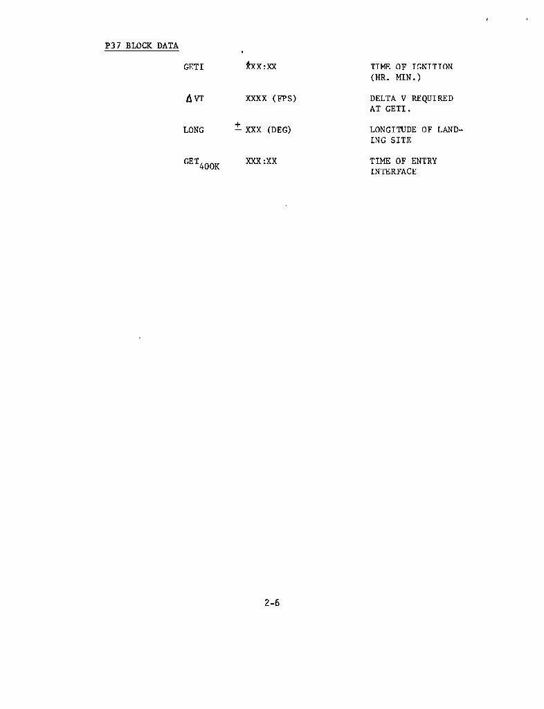
P37 BLOCK DATA
GETI *XX:XX TIME OF IGNITION
(HR. MIN.)
A VT XXXX (FPS) DELTA V REQUIRED
AT GETI.
LONG ± XXX (DEG) LONGITUDE OF LAND-
ING SITE
GET400XXX :XX TIME OF ENTRY
KINTERFACE

P27 UPDATE
PURP V V V
GET
304 01 IN DEX IN DEX IN DEX
02
03
04
05
06
07
10
11
12
13
14
15
16
1720
21
22
23
24
N34 HRS X X X X X X
MIN X X X X X X X X
NAV CHECK SEC X X X XN43 LAT 0 0
LONGALT + 0 + 0
2-7
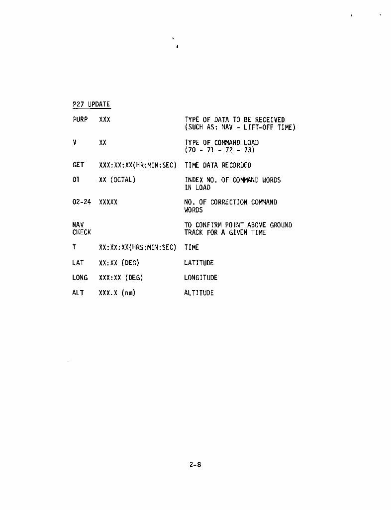
P27 UPDATE
PURP XXX TYPE OF DATA TO BE RECEIVED(SUCH AS: NAV - LIFT-OFF TIME)
V XX TYPE OF COh44AND LOAD(70 - 71 - 72 - 73)
GET XXX:XX:XX (HR:MIN:SEC ) TIME DATA RECORDED
01 XX (OCTAL) INDEX NO . OF COMMAND WORDSIN LOAD
02-24 XXXXX NO. OF CORRECTION COMMANDWORDS
NAV TO CONFIRM POINT ABOVE GROUNDCHECK TRACK FOR A GIVEN TIME
T XX:XX:XX( HRS:MIN:SEC) TIME
LAT XX:XX (DEG) LATITUDE
LONG XXX: XX (DEG ) LONGITUDE
ALT XXX.X (nm) ALTITUDE
P30'MANEUVER4
PURPOSE
SET STARS 11 PROP/GUID
+ WT N47RALIGN 0 0 P
TR1M N48-- -
P AlIGN_ 0 0 YTR1M- -
Y + 0 0 HRS GET1ALlGN ___+ 0 0 0 MIN N33+ 0 SEC
ULLAGE6VX NBT/:,VyI:N Z
X X X R
X X X P
X X X Y
+ HA N44Hp
+ 6VT
HORIZON/WINDOW _ X X X 8T
X 6V(
X X X X SXTS
+ 0 SFT+ a 0 TRN
X X X BSS
X X SPA
X X X SXP
OTHER 0 LAT N6l
LONG
+ RTGO EMS
+ Vla
I GET O.05G
2-9
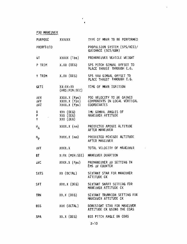
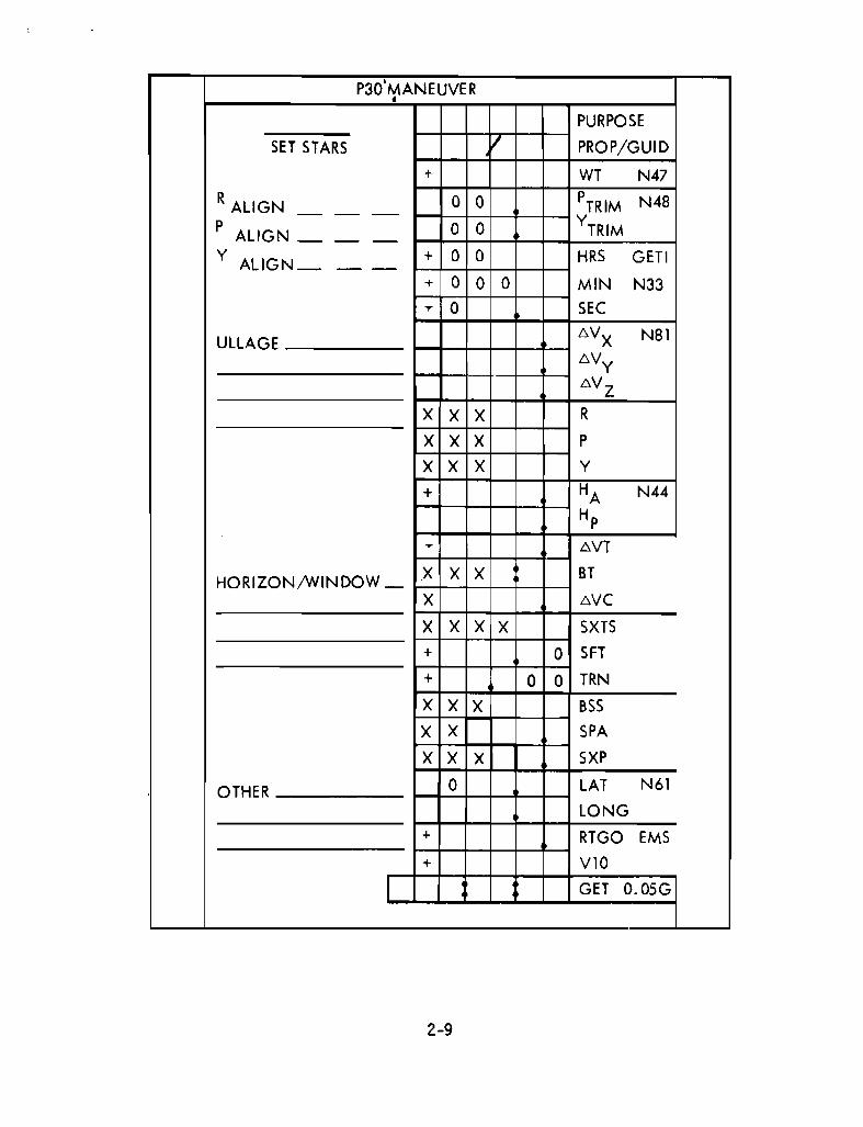
P30 MANEUVER
PURPOSE XXXXXX TYPE OF MNVR TO BE PERFORMED
PROP/G UID PROPULSION SYSTEM (SPS/RCS)/GUIDANCE (SCS/G&N)
WT XXXXX (lbs) PREMANEUVER VEHICLE WEIGHT
P TRIM X.XX (DEG) SPS PITCH GIMBAL OFFSET TOPLACE THRUST THROUGH C.G.
Y TRIM X.XX (DEG) SPS YAW GIMBAL OFFSET TOPLACE THRUST THROUGH C.G.
GE TI XX:XX:XX TIME OF NNVR IGNITION(HRS:M IN:SEC)
MVX XXXX.X (fps) P30 VELOCITY TO BE GAINEDMVY XXXX.X (fps) COMPONENTS IN LOCAL VERTICALAVZ XXXX.X (fps) COORDINATES
R XXX (DEG) IMU GIMBAL ANGLES OFP XXX (DEG) MANEUVER ATTITUDEY XXX (DEG)
HA XXXX.X (nm) PREDICTED APOGEE ALTITUDEAFTER MANEUVER
HP XXXX.X (nm) PREDICTED PERIGEE ALTITUDEAFTER MANEUVER
MVT XXXX.X TOTAL VELOCITY OF MANEUVER
BT X:XX (MIN:SEC) MANEUVER DURATION
AVC XXXX.X (fps) PREMANEUVER AV SETTING INEMS AV COUNTER
S XTS XX (OCTAL) SEXTANT STAR FOR MANEUVERATTITUDE CK
S FT XXX.X (DEG) SEXTANT SHAFT SETTING FORMANEUVER ATTITUDE CK
TRN XX.X (DEG) SEXTANT TRUNNION SETTING FORMANEUVER ATTITUDE CK
B55 XXX (OCTAL) BORESIGHT STAR FOR MANEUVERATTITUDE CK USING THE COAS
SPA XX.X (DEG) BSS PITCH ANGLE ON COAS
2-10

MANEUVER PAD (cont'd)
SXP X .X (DEG ) BSS X POSITION ON COAS
LAT XX.XX LATITUDE AND LONGITUDE OF THELONG XXX . XX LANDING POINT FOR ENTRY
GUIDANCE
RTGO XXXX.X RANGE TO GO FOR EMSINITIALIZATION
VIO XXXXXX (fps) INERTIAL VELOCITY AT . 05G FOREMS INITIALIZATION
GET(.05G) XX:XX:XX TIME OF .05G
SET STARS STARS FOR TELESCOPE FORBACKUP GDC ALIGN
R, P, Y ATTITUDE TO BE SET IN(ALIGN) ATTITUDE SET TW FOR BACKUP
GDC ALIGN
ULLAGE NO. OF SM RCS JETS USED ANDLENGTH OF TIME OF USSAGE
HORIZON WINDOW MARKING AT WHICHWINDOW HORIZON IS PLACED AT A
SPECIFIED TIG (ATT CK)
2-11
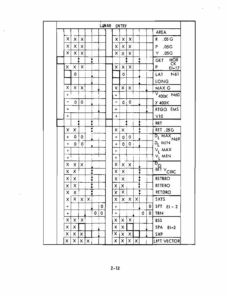
.LUNAR ENTRY
AREA
X X X X X X R .05G
X X X X X X P .05GX X X X X X Y .05G
• : GET HOR
! CKX X X : X X X P EI-17,
0 I 0 LAT N61
LONG
X X X X X X MAX G
+ i + i V400K N60
0,
OiO- 0 - I Y 400K
+ +,
RTGO EMS
+ , + VIO
l : I RRT,
X xi • XiX !,
RET .05(,• I
O!O ! I + 0,0, ! DL MAX
N69+ ,
+ 0 0: ! + OiO DL MIN,+ ! + , , VL MAX
I
+ , + , VL
MIN
X X X, X X X IDo
X X X,X RET VCIRC
X X I xix I RETBBO
X X,
X 'X RETEBO•X X I X X • RETDROI
X X X X,
X X X X SXTS•
0,
0 SFT EI - 2+ +
+ 0 0 + 0 0 TRN
X X X,
X X X BSSI
X X • X X SPA EI-2
X X X X X X SXP
X X X X X X X X LIFT VECTOR
2-12

I
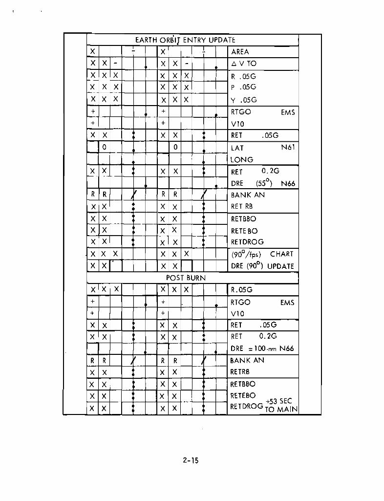
EARTH ORBIJ ENTRY UPDATE
X ~ X ! AREA
X X - X X - 6 V TO
X X X X X X R .05G
X X X X X X P .05G
X X X X X X Y .05G
+ + RTGO EMS
+ + V10
X X X X RET .05G
0 0 LAT N61
LONG
X X X X RET 0.2G
DRE (55°) N66
R R ~ R R '( BANK ANI
X X X X RET RB
X X X X RETBBO
X X X X RETE BO
X X X X RETDROG
X X X X X X (90°/fps) CHART
X X X X DRE (90°) UPDATE
POST BURN
X X X X X X R.05G
+ + RTGO EMS+ + V10
X X X X RET .05G
X X X X RET O.2G
DRE ± l00-nm N66
R R ~ R R II BANK ANi i
X X X X RETRB
X X X X RETBBO
X X X X RETEBO C+53 SE
X X X X RETDROG TO MAIN
2-15
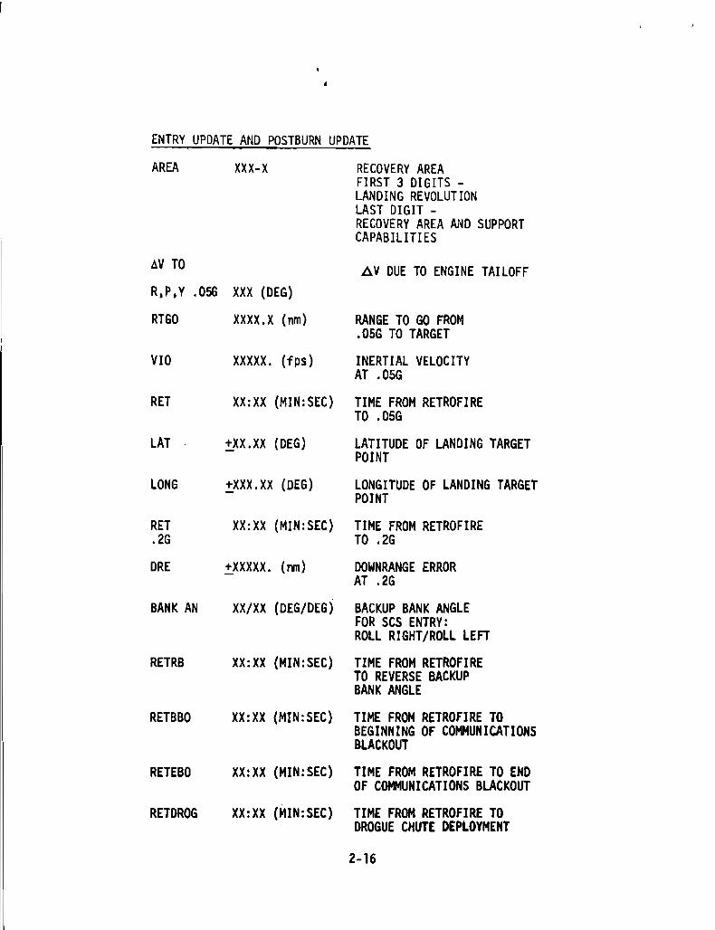
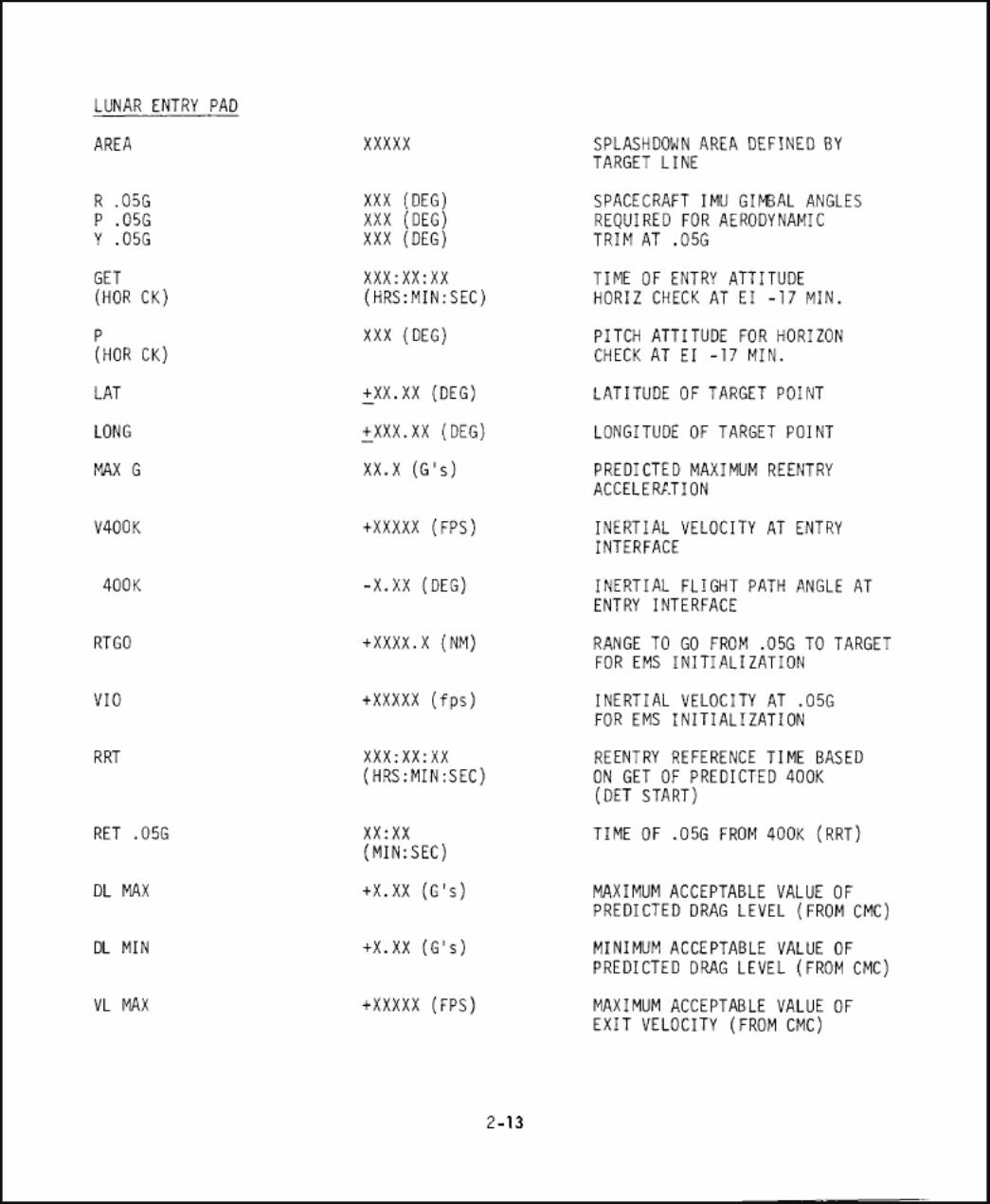
ENTRY UPDATE AND POSTBURN UPDATE
AREA XXX-X RECOVERY AREAFIRST 3 DIGITS -LANDING REVOLUTIONLAST DIGIT -RECOVERY AREA AND SUPPORTCAPABILITIES
t:.V TO L>V DUE TO ENGINE TAILOFFR,P,Y .05G XXX (DEG)
RTGO XXXX.X (nm) RANGE TO GO FROM.05G TO TARGET
VIO XXXXX. (fps) INERTIAL VELOCITYAT .05G
RET XX:XX (MIN:SEC) TIME FROM RETROFIRETO .D5G
LAT :':.XX.XX (DEG) LATITUDE OF LANDING TARGETPOINT
LONG :':.XXX.XX (DEG) LONGITUDE OF LANDING TARGETPOINT
RET XX:XX (MIN:SEC) TIME FROM RETROFIRE.2G TO .2G
ORE :':.XXXXX. (nm) DOWNRANGE ERRORAT .2G
BANK AN XX/XX (DEG/DEG) BACKUP BANK ANGLEFOR SCS ENTRY:ROLL RIGHT/ROLL LEFT
RETRB XX:XX (MIN:SEC) TIME FROM RETROFIRETO REVERSE BACKUPBANK ANGLE
RETBBO XX:XX (MIN:SEC) TIME FROM RETROFIRE TOBEGINNING OF COMMUNICATIONSBLACKOUT
RETEBO XX:XX (MIN:SEC) TIME FROM RETROFIRE TO ENDOF COMMUNICATIONS BLACKOUT
RETDROG XX:XX (MIN:SEC) TIME FROM RETROFIRE TODROGUE CHUTE DEPLOYMENT
2-16
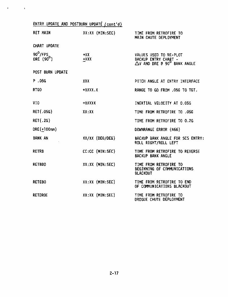
ENTRY UPDATE AND POSTBURN UPDATE cont'd
RET MAIN XX:XX (MIN:SEC)
CHART UPDATE
90°/FPSORE (90°)
POST BURN UPDATE
P .05G
RTGO
VIO
RET(.05G)
RET( .2G)
DRE(+IOOnm)
BANK AN
RETRB
RETBBO
+XX+XXX
xxx
+XXXX.X
XX/XX ( DEG/DEG)
CC:CC (MIN:SEC)
XX:XX (MIN:SEC)
RETEBO XX:XX (MIN:SEC)
RETDROC XX:XX (MIN:SEC)
TIME FROM RETROFIRE TOMAIN CHUTE DEPLOYMENT
VALUES USED TO RE-PLOTBACKUP ENTRY CHAT -,n^V AND DRE @ 90 BANK ANGLE
PITCH ANGLE AT ENTRY INTERFACE
RANGE TO GO FROM .05G TO TGT.
INERTIAL VELOCITY AT 0.05G
TIME FROM RETROFIRE TO .05G
TIME FROM RETROFIRE TO 0.2G
DOWNRANGE ERROR (N66)
BACKUP BANK ANGLE FOR SCS ENTRY:ROLL RIGHT/ROLL LEFT
TIME FROM RETROFIRE TO REVERSEBACKUP BANK ANGLE
TIME FROM RETROFIRE TOBEGINNING OF COMMUNICATIONSBLACKOUT
TIME FROM RETROFIRE TO ENDOF COMMUNICATIONS BLACKOUT
TIME FROM RETROFIRE TODROGUE CHUTE DEPLOYMENT

EARTH ORBIT BLOCK DATA
X X X X AREA
X X X X X X LAT
X X X X LONG
GETI
X X X X X X 1WC
X X X X AREA
X X X X X X LAT
X X X X LONG
GETI
X X X X X XAVC
X X X X AREA
X X X X X X LAT
X X X X LONG
GETI
X X X X X X avC
X X X X AREA
X X X X X X LAT
X X X X LONG
GETI
X X X X X X 1 IAVC
X X X X AREA
X X X X X X LAT
X X X X LONG
GETI
X X X X X XoVC
REMARKS:
2-18
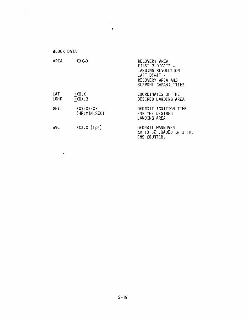
BLOCK DATA
AREA xxx -x RECOVERY AREAFIRST 3 DIGITS -LANDING REVOLUTIONLAST DIGIT -RECOVERY AREA ANDSUPPORT CAPABILITIES
LAT +XX.X COORDINATES OF THELONG +XXX.X DESIRED LANDING AREA
GETI XXX:XX:XX DEORBIT IGNITION TIME(HR:MIN:SEC ) FOR THE DESIRED
LANDING AREA
aVC XXX.X (fps) DEORBIT MANEUVERAV TO BE LOADED INTO THEEMS COUNTER.

8',1,hrO~O'------i' 000 : 0LL.--,-~PL--,----,DL~
br-"--'--O·1
TPI
CSI TWO
CSM RENDEZVOUSRESCUE PADS
CSI ONE
7 00 • 000 :• 0 .1 . . .9 .T XX • xx • xx •• • •
eOH
81,ll==_0_0_~. 000 • 0
L_~p,-----,~bL--=----
:br.~oo'-.---'5 000 •
3
85
S 8
EXTERNAL DV PADS
CSM SEP PAD NOMINAL LM IGNITION TIMES3 00 • 000 • 0 CSI 11 00 • 000 • 0• • • • ·1 ;foooo.o + I 0000.0 -I 0002.5 PC 33 00 • 000 • 0• • ·2 XXX XXX TPI 37 00 • 000 • 0• • ·
CSM BACKUPINSERTION PAD
INITIALRE~C E TW" PAD
7 + . + 00000. 47 + . + 00000.8 . '" ..3 00 • 000 • 0 33 00 • 000 • 0• • · • • ·, T T . . 81 r . I . I .2 XXX XXX XXX 22 XXX XXX XXX
e X · AVe X .1 00 • 000 0 00 • 000 • 0• • · 11 .7 00 ~ 000 0 37 00 • 000 • 0• · • • ·I , T
CSM BACKUPINSERTION PAD
UPDATE7 + . + 00000.8 . CANNED RESCUE TWO PADS FOR:3 00 • 000 • 0 1. PARTIAL PHASING (0 - 40)• ·1 I I 2. PARTIAL PHASING (40 - NOM) LO· . .2 XXX XXX XXX 3. PARTIAL INSERTION
X ARE INCLUDED ON RESCUE CHECKLISTSe ·1 00 • 000 • 0• ·7 00 • 000 • 0• • ·
1
44
3
8
2AV
13,
3
8
2
4
4
3
82
AV
1
3,
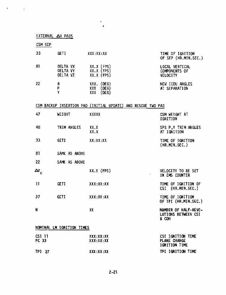
EXTERNAL &V PADS
CSM SEP
33 GETI XXX :XX:XX TIME OF IGNITIONOF SEP (HR.MIN.SEC.)
81 DELTA VX XX.X (FPS) LOCAL VERTICALDELTA VY XX.X (FPS) COMPONENTS OFDELTA VZ XX.X (FPS) VELOCITY
22 R XXX . (DEG) NEW ICDU ANGLESP XXX (DEG) AT SEPARATIONY XXX (DEG)
CSM BACKUP INSERTION PAD (INITIAL UPDATE) AND RESCUE TWO PAD
47 WEIGHT XXXXX CSM WEIGHT ATIGNITION
48 TRIM ANGLES XX.X SPS P,Y TRIM ANGLESXx.x AT IGNITION
33 GETI XX:XX:XX TIME OF IGNITION(H R. MI N. SEC.)
81 SAME AS ABOVE
22 SAME AS ABOVE
AVc XX.X (FPS) VELOCITY TO BE SETIN EMS COUNTER
11 GETI XXX:XX:XX TIME OF IGNITION OFCSI (HR.MIN.SEC.)
37 GETI XXX:XX:XX TIME OF IGNITIONOF TPI (HR.MIN.SEC.)
XX NUMBER OF HALF-REVO-LUTIONS BETWEEN CSI& CDH
NOMINAL LM IGNITION TIMES
CSI 11 XXX:XX:XX CSI IGNITION TIMEPC 33 XXX:XX:XX PLANE CHANGE
IGNITION TIME
TPI 37 XXX:XX:XX TPI IGNITION TIME
2-21
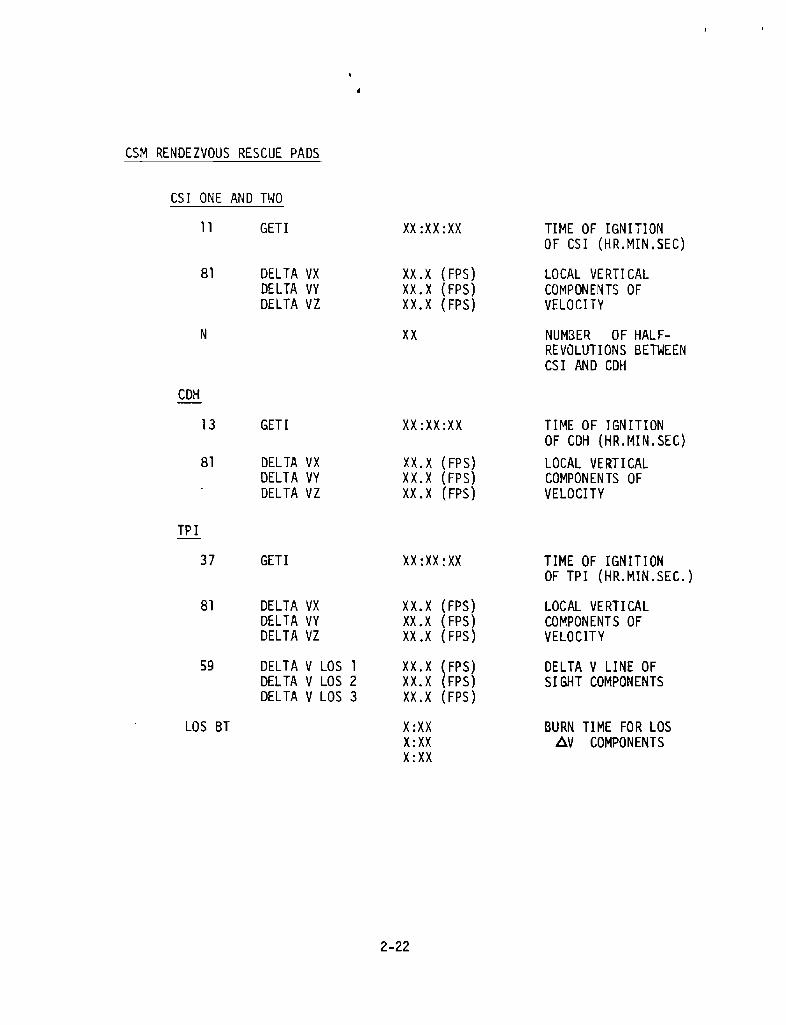
CSM RENDEZVOUS RESCUE PADS
CSI ONE AND TWO
11 GETI XX:XX:XX TIME OF IGNITIONOF CSI ( HR.MIN.SEC)
81 DELTA VXDELTA VYDELTA VZ
XX.X (FPS)XX.X (FPS)XX.X (FPS)
LOCAL VERTICALCOMPONENTS OFVELOCITY
N XX NUMBER OF HALF-REVOLUTIONS BETWEENCSI AND CDH
CDH
13 GETI XX:XX:XX TIME OF IGNITIONOF CDH ( HR MIN SEC). .
81 DELTA VXDELTA VYDELTA VZ
XX.X (FPS)XX.X (FPS)XX.X (FPS)
LOCAL VERTICALCOMPONENTS OFVELOCITY
TPI
37 GETI XX:XX:XX TIME OF IGNITIONOF TPI (HR.MIN.SEC.)
81 DELTA VXDELTA VYDELTA VZ
XX.X (FPS)XX.X (FPS)XX.X (FPS)
LOCAL VERTICALCOMPONENTS OFVELOCITY
59 DELTA V LOS 1DELTA V LOS 2DELTA V LOS 3
XX.X (FPS)XX.X (FPS)XX.X (FPS)
DELTA V LINE OFSIGHT COMPONENTS
LOS BT X:XXX:XXX:XX
BURN TIME FOR LOSAV COMPONENTS

LM
MANEUVER
UPDATE FORMS
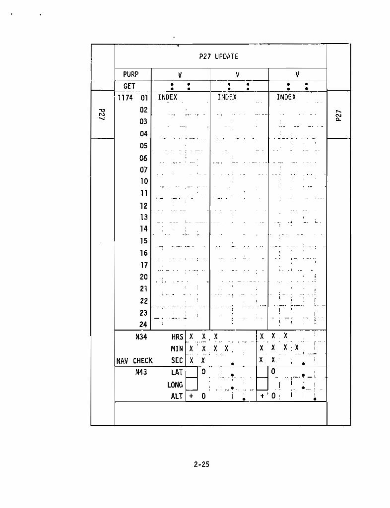
P27 UPDATE
PURP
GET
1174 01
02
03
INDEX INDEX INDEX
04
05
06
07
10
11
12
13
14
15
16
17
20
21
22
23
24
N34 HRS
MIN
NAV CHECK SEC
X X XX X X X
X X
X X 1 XX X X X
X XN43 LAT
LONG
0 0
ALT + 0
2-25

P27 UPDATE
PURP XXX TYPE OF DATA TO BE RECEIVED(SUCH AS: NAV - LIFT-OFF TIME)
V XX TYPE OF COMMAND LOAD(70 - 71 - 72 - 73)
GET XXX:XX:XX(HR:MIN:SEC) TIME DATA RECORDED
01 XX (OCTAL ) INDEX NO. OF COMMAND WORDS.IN LOAD
02-24 XXXXX NO. OF CORRECTION COMMANDWORDS
NAV TO CONFIRM POINT ABOVE GROUNDCHECK TRACK FOR A GIVEN TIME
T XX:XX:XX(HRS:MIN:SEC) TIME
LAT XX:XX (DEG) LATITUDE
LONG XXX:XX (DEG) LONGITUDE
ALT XXX.X (nm) ALTITUDE
2-26

REMARKS:
AGS STATE VECTOR UPDATE
PURP
240
241
242
260
261
262
254
244
245
246
264
265
266
272
2-27
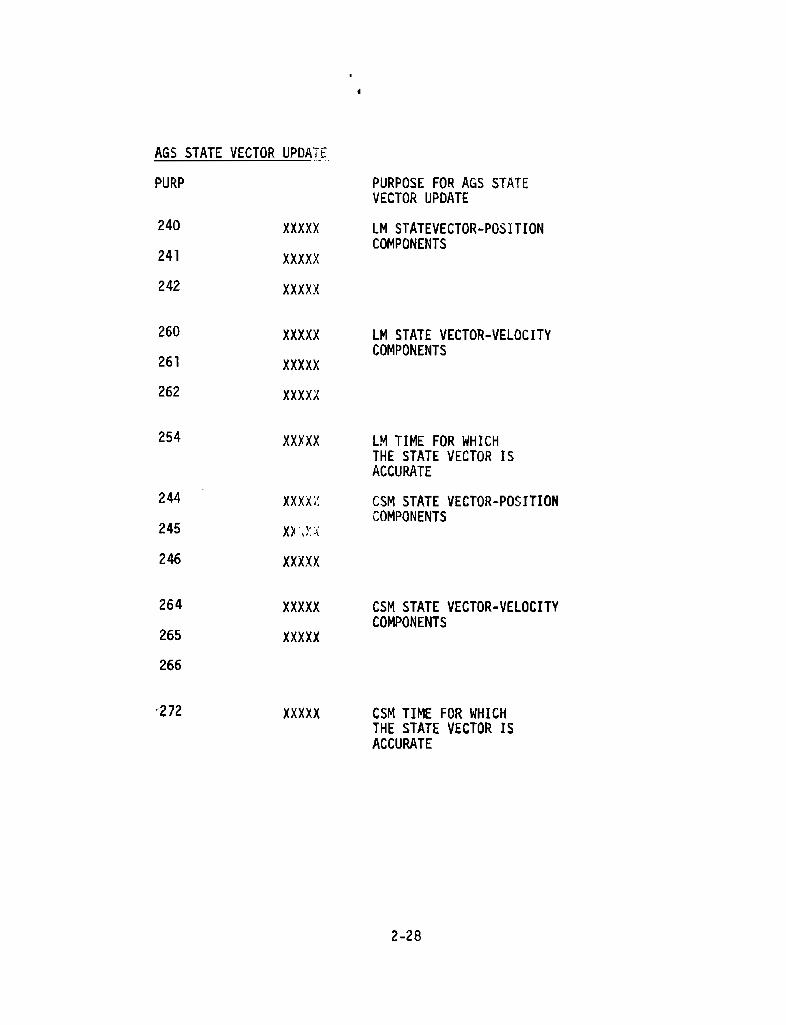
AGS STATE VECTOR UPDATE
PURP PURPOSE FOR AGS STATEVECTOR UPDATE
240 XXXXX LM STATEVECTOR-POSITIONCOMPONENTS
241 xxxxx242 xxxxx
260 XXXXX LM STATE VECTOR-VELOCITYCOMPONENTS
261 xxxxx262 xxxxx
254 XXXXX LM TIME FOR WHICHTHE STATE VECTOR ISACCURATE
244 xxx x CSM STATE VECTOR-POSITIONCOMPONENTS
245 XX LX
246 xxxxx
264 xxxxx CSM STATE VECTOR-VELOCITYCOMPONENTS
265 xxxxx266
'272 xx xxx CSM TIME FOR WHICHTHE STATE VECTOR ISACCURATE
·_.
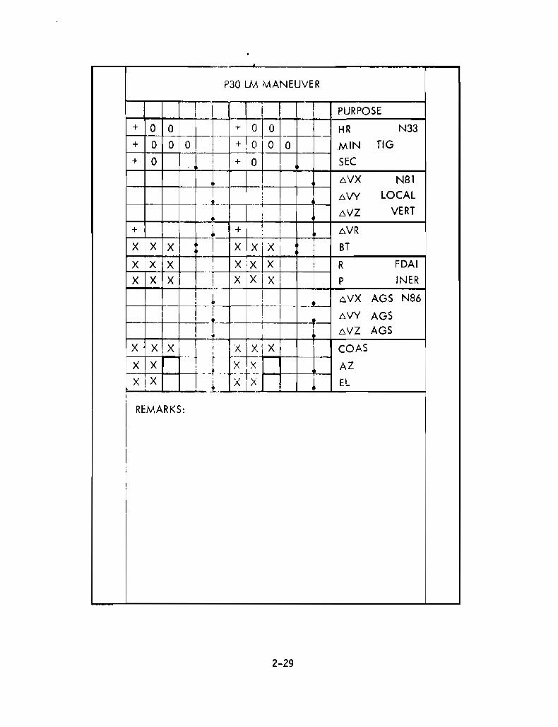
P30 LM MANEUVER
! I PURPOSE
+ 0 0 l-*0HR N33
+ ola ._-f-i-+ 0 0 g__ I 0 .MIN TIG
+ 0 I + 0 SEC,
I 6VX N81c_ -- - --j
6VY LOCAL-.,-!:- --
I 6VZ VERTI
+ ; +,
6VR•I -X X XI , X XiX BT
X X X X X X R FDAI
X X X--_.._-,-
X X X INERI P-,--I! ,
6VX AGS N86, ,I--- t--- ~,
6VY AGS,-1!
,6VZ AGS,, ,
~
X X X i: x x' X COAS
X X ! ',- x* AZ
XiX '; -x-tX I EL
I
_1 __:L
REMARKS,
I,,iI
2-29

LM MANEUVER UPDATE
PURPOSE PURPOSE OF MANEUVER(SUCH AS DOCKED DPS,PHASING, INSERTION)
TIG IGNITION TIME FOR THE MANEUVER
HR xxx
MIN xx
SEC XX.XX
LOCAL VERT
AVX +XXXX.X(fps) LOCAL VERTICAL AVCOMPONENTS OF THE
MVY +XXXX.X(fps) MANEUVER
MVZ +XXXX.X(fps)
MVR XXXX.X(fps) TOTAL AV REQUIREDFOR THE MANEUVER
BT X:XX BURN DURATIONFDAI INER
R XXX (DEG) INERTIAL FDAIANGLES AT THE
P XXX (DEG) BURN ATTITUDE
MVX AGS +XXXX.X(fps) LOCAL VERTICAL AVCOMPONENTS OF THE
MVY AGS +XXXX.X(fps) MANEUVER USED TOTARGET THE AGS;
AVZ AGS +XXXX.X(fps ROTATED THROUGH THEHALF-ANGLE OF THE BURN
COAS XX(OCTAL) IDENTIFIER FOR COAS STARUSED TO VERIFY SPACECRAFTATTITUDE AT THE BURN ATTITUDE
AZ XXX (DEG) THE AZIMUTH AND ELEVATIONANGLES OF THE COAS STAR
EL XXX (DEG)
2-30
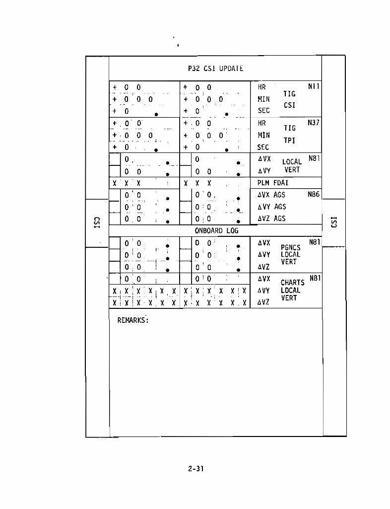
P32 CSI UPDATE
+ 0 0 + 0 0 HR N11- __. ..: _ _.. _. _. _.. TIG
0 0 + 0 0 0 MINCSI
+ 0 + 0 SEC
+ 0 0 +. 0 0 HR N37TIG
+ 0 0 0 + 0 0 0 MINTPI
+ 0 + 0 • SEC
0 0 0 • AVX LOCAL N81
0 0 0 0 AVY VERT0 •
X X X X X X PLM FDAI
0 0 • 0 0 • AVX AGS N86 _
0 0 0 0 0 AVY AGS. ,
ti 0 0 , 0 0 AVZ AGS
ONBOARD LOG
- 0 - 0 0 0 ' AVX N81PGNCS
0 0. 0 0 ; AVY LOCALVERT
0 00
0 AVZ
0 0 0 0 AVX CHARTSN81
X X X X X X X X X' X XX AVY LOCAL
X X i x:1
X X X X X X X
,
X. X AVZ VERT
REMARKS :
2-31

CSI UPDATE
TIG CSI IGNITION TIME FOR THECSI MANEUVER
HR XXX
MIN xx
SEC xx.xx
TIG TPI IGNITION TIME FOR THETPI MANEUVER
HR XXX
MIN xxSEC XX.Xx
LOCAL VERT
AVX +XX.X (fps)LOCAL VERTICAL
AVY +XX.X (fps) AV COMPONENTSOF THE CSIMANEUVER
PLM FDAI XXX (DEG) LM FDAI INERTIALPITCH ANGLE ATCSI BURN ATTITUDE
AVX AGS +XX.X (fps) LOCAL VERTICAL AVCOMPONENTS OF CSI
AVY AGS +XX.X (fps) USED TO TARGET AGSEXT AV; ROTATED
AVZ AGS +XX.X (fps) THROUGH THE HALF-ANGLE
ON BOARD LOGS OF THE BURN
AVX PGNCS +XX.X
AVY LOCAL +XX.X
AVZ VERTICAL +XX. X
AVX CHARTS
AVY LOCAL
AVZ VERTICAL
+XX.X+XX. X+XX.X
2-32

P33 COH UPDATE
+ 10 0 ii + o i 0 , HR N13,
- ..,.--- r I .•_- i --,-, ..., .-_.. . -- ._- ,
TIG+; 0 '0 O' . + 0 0 O. MIN•...• , ...... 1' " -_.. -, -_.. • '0" , COH+ 0 i + o· SEC•
- 0 • - 0 • 6VX N8T,- - ~.,~.- " LOCAL0 0 0 0 6VY- .. _. ----• - , --- - • - VERT0 0 0 0 6VZ•
X ex x x X PlM FOAl0 0
"
6VX AGS N86- , -- • - ,
- 0 0 - 0 0 • 6VY AGS.-.- " .'---. ,._- " " . ,
0 0 0 0 6VZ AGSONBOARO lOG
f-0 0
f- 0 0 6VX PGNCS N81,- ,.
., . •0 0 0 0 6VY LOCAL
f- , .." .. -- -'; _.' - f- - , • VERTO' 0 0 0 6VZ•0 .0 0 0 • 6VX CHARTS N81
•n X X X X X X X X X X X X LOCAL
"00 VERT '"" 0 0 0 6VZ u
• •REMARKS:
2-33

CDH UPDATE
TIG CDH IGNITION TIME FOR THECDH MANEUVER
HR xxxMIN xxSEC xx.xx
LOCAL VERT
AVX ±XX.X (fps)LOCAL VERTICAL AV
AVY +XX.X (fps) COMPONENTS OFTHE CDH MANEUVER
AVZ +XX.X (fps)
PLM FDAI XXX (DEG) LM FDAI INERTIALPITCH ANGLE ATCDH BURN ATTITUDE
AVX AGS ±XX.X (fps) LOCAL VERTICAL AVCOMPONENTS OF CDH
AVY AGS +XX.X (fps) USED TO TARGET AGSEXT AV; ROTATED
AVZ AGS +XX.X (fps) THROUGH THE HALF-ANGLEOF THE BURN
ONBOARD LOGAVX PGNCS +XX.X (fps )
AVY LOCAL +XX.X (fps)
AVZ VERTICAL +XX.X (fps)
AVX CHARTS +Xx.x (fps)LOCAL
AVZ VERTICAL +XX.X (fps)
2-34
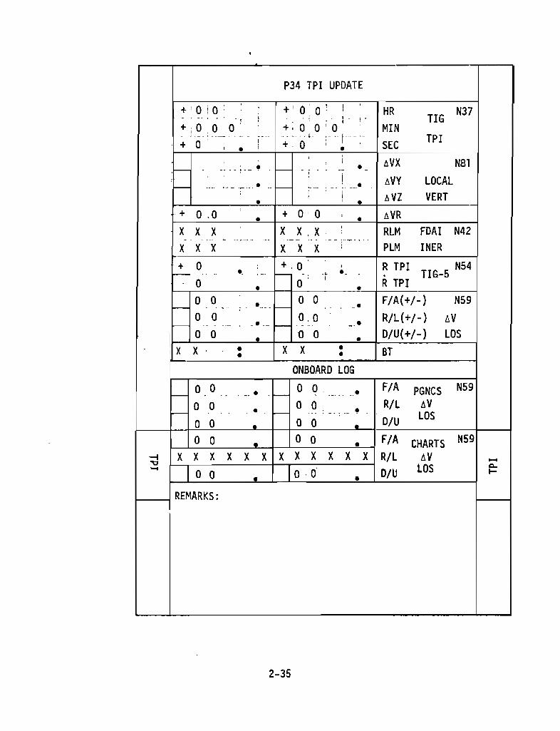
P34 TPI UPDATE
+' 0: 0 +' 0' 0 ' ! HR N37, , ,. TlG, ,+ i 00 0' +, 0 0'0 MIN
---~ ..- .. -- -.' ... ,0- I -- .._. TPI+ 0
, + 0 SEC, •,
• ,I ~VX N81- --- - - t-- • - ., ·--,!• • ~VY LOCAL- .... - --,, ,
~ VZ VERT• , •+ o .0 + o ' 0 ~VR• •X X X X X,X
,RLM FOAl N42
, - -"-,,.... -- .- -- -- -- ., --
X X X X X X PLM INER+ 0 + 0 , R TPI TlG-5 N54f-- • . f- , •., .
0 • 0 • R TPI0 0 • 0 0 F/A(+/-} N59
I-- ' . .. -- e- , •0 0 0, 0 R/L(+/-) ~V
f-- . . ---- _. -- f- , •I
0 0 • 0 0 • D/U(+/-) LOS• X X •i X X • • BT
ON80ARD LOG0 0 0 0 • F/A PGNCS N59
I-- . , -- • e- , .-
0 0 0 0 R/L ~VI-- - -_.. • - e- .. · --- • LOS
0 0 • 0 0 D/U0 0 0 0 F/A CHARTS N59•
-l X X X X X X X X X X X X R/L ~V -"'" LOS "'-- I 0 10 00 D/U >-• •
REMARKS:
2-35
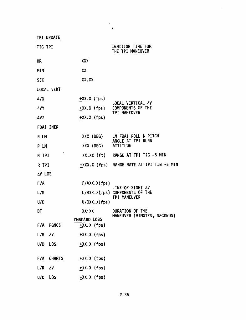
TPI UPDATE
TIG TPI IGNITION TIME FORTHE TPI MANEUVER
HR xxx
MIN xx
SEC XX.XX
LOCAL VERT
AVX +XX.X (fps)LOCAL VERTICAL AV
AVY +XX.X (fps) COMPONENTS OF THETPI MANEUVER
AVZ +XX.X (fps)
FDAI INER
R LM XXX (DEG ) LM FDAI ROLL & PITCHANGLE AT TPI BURN
P LM XXX (DEG) ATTITUDE
R TPI XX.XX ( ft) RANGE AT TPI TIG -5 MIN
R TPI +XXX.X (fps) RANGE RATE AT TPI TIG -5 MIN
AV LOS
F/A F/AXX.X(fps)LINE-OF-SIGHT AV
L/R L/RXX.X(fps) COMPONENTS OF THETPI MANEUVER
U/D U/DXX .X(fps)
BT XX:XX DURATION OF THEMANEUVER (MINUTES, SECONDS)
ONBOARD LOGS
F/A PGNCS ±XX.X (fps)
L/R AV +XX.X (fps)
U/D LOS +XX.X (fps)
F/A CHARTS +XX.X (fps)
L/R AV +XX.X (fps)
U/D LOS +XX.X (fps)
2-36

P76 UPDATE PAD
PURPOSE
+ 0 0 + 0 0 HR N33
+ 0 0 0 + 0 0 0 MIN TIG
+ 0 + 0 SEC• • AVX N84
• • AVY
• • AVZ
PURPOSE'ov
0 0 + 0 0 HR N33
+ 0 0 0 + 0 0 0 MIN TIG
+ 0 + 0 • SECAVX N84
• • AVY TIG
• • AVZ
PURPOSE
+ 0 0 + 0 0 HR N33
+ 0 0 0 + 0 0 0 MIN TIG
+ 0 + 0 • SEC
• • AVX N84
' • AVY
• AVZ
PURPOSE
* 0 0 + 0 0 HR N33
+ 0 0 0 + 0 0 0 MIN TIG
+ 0 + 0 SEC
• • AVX N84
• • AVY• • AVZ
2-37
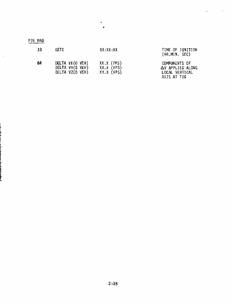
P76 PAD
33 GETI XX:XX:XX TIME OF IGNITION(HR.MIN. SEC)
84 DELTA VX (O VEH)DELTA VY( O VEH )DELTA VZ(O VEH)
XX.XXX.XXX.X
(FPS)(FPS)(FPS)
COMPONENTS OFAV APPLIED ALONGLOCAL VERTICALAXIS AT TIG
SECTION 3 - DETAILED TIMELINE

FLIGHT PLANTIME EVENT REMARKS
-00:09 LCC: REPORT IGNITION FIRST OPPORTUNITY LIFT-OFF MAY lB,124B EDT, 72° LA, TARGETED FOR LANOING
00:00 LCC: CDR: REPORT LI FT-OFF SITE 2. LIFT-OFF: 1648 GMT1148 EST
00:02 CDR: REPORT YAW MNVR 1148 COT1048 CST
00:11 CDR: REPORT ROLL ANO PITCH PROGRAMINITIATE
00:30 CDR: REPORT ROLL COMPLETE
00:42 MCC: REPORT MARK MODE IB PROP DUMP TO RCS CMD .00:50 LMP: REPORT CABIN PRESS DECREASING ALTITUDE 14,000 ft
01 :17 MAXQ
01:56 MCC: REPORT MARK MODE IC ALTITUDE 100,000 ft
02:00 MCC: CDR: REPORT GO/NO GO FOR STAGING
02: 16 CDR: REPORT INBOARD OUT
02:40 CDR: REPORT OUTBOARD OUT
02:41 CDR: REPORT STAGING
03: 11 CDR: REPORT S-II SEP LIGHT OUT
03:16 CDR: REPORT TWR JETT AND MODE II
03:21 CDR: REPORT GUI DANCE
03:53 MCC: REPORT TRAJECTORY AND GUIDANCE GO/NO GO
MISSON F IEDITION FINAL IDATE APRIL 17, 1969 IPAGE 3-1MSC FORM 2114C (JUL 67)
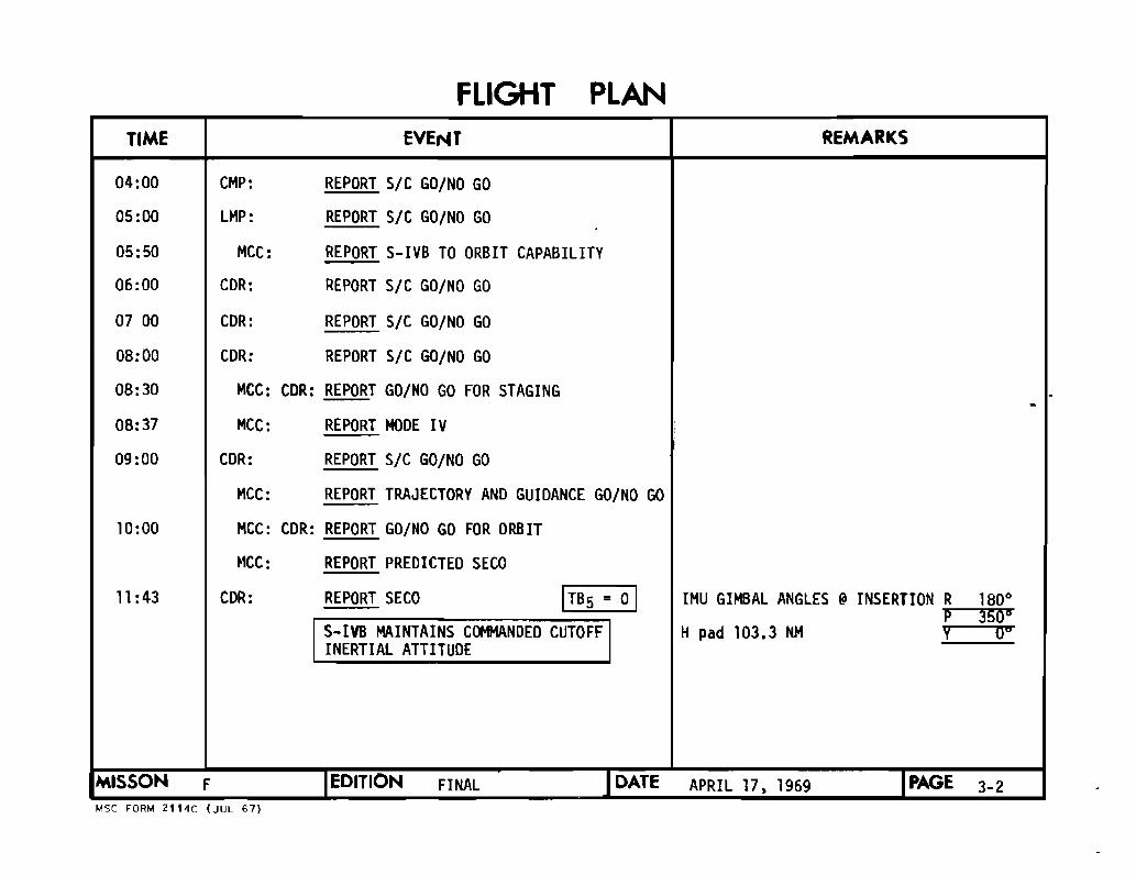
FLIGHT PLANTIME EVENT REMARKS
04:00 CMP: REPORT SIC GO/NO GO
05:00 LMP: REPORT SIC GO/NO GO
05:50 MCC: REPORT S-IVB TO ORBIT CAPABILITY
06:00 COR: REPORT SIC GO/NO GO
07 00 COR: REPORT SIC GO/NO GO
08:00 COR: REPORT SIC GO/NO GO
08:30 MCC: COR: REPORT GO/NO GO FOR STAGING ..08:37 MCC: REPORT MOOE IV
09:00 COR: REPORT SIC GO/NO GO
MCC: REPORT TRAJECTORY ANO GUIOANCE GO/NO GO
10:00 MCC: COR: REPORT GO/NO GO FOR ORB IT
~'CC : REPORT PREDICTED SECO
11 :43 CDR: REPORT SECO ITB5 = 01 IMU GIM8AL ANGLES @ INSERTION R 180'P 350'
S-IVS MAINTAINS COMMANDED CUTOFF H pad 103.3 NM Y 06
INERTIAL ATTITUDE
MISSON F IEDITION FINAL IDATE APRIL 17. 1969 TPAGE 3-2MSC FORM 2114C (JUL 67)

FLIGHT PLANTIME EVENT REMARKS
SECO r MCC: REPORT ORBITAL GO/NO GO INSERTION+10 SEC
SECO S-IVB MANEUVERS TO LH ANO ITITIATES+20 SEC ORB RATE (HEADS DOWN) ..
INSERTION CHECKLIST
SECO S-IVB INITIATES CONTINUOUS LH2+59 SECVENTING (TERMINATES AT TB6 + 42.2 SEC) ..
12:41 BOA LOS
16:28 CYI ADS
MCC UPOATE: GO FOR OSE REWI~D
23:35 CYI LOS
POST INSERTION ECS CONFIGURATION
MISSON F IEDITION FINAL IOATE APRIL 17 1969 1PAGE 3-3MSC FORM 2114C (JUL 671

FLIGHT PLANTIME EVENT REMARKS
CONFIGURE CAMERA FOR T &0AND S-IVB PHOTO
CM/SEQ/1B/CEX-BRKT(RH WIN)
MIR (f11.250.~)12 fps. 7 MIN)
32:00 SIC SUNSET CM/EL/80/CEX-SPOT (5.250.focus)20
36:30 TAN AOS
I MCC UPDATE: AAZ CORRECTION
42:32 TAN LOS
CDR INSTALL COAS .CMP JETTISON OPTICS COVERS
P52 IMU REALIGN REALIGNS to PAD ORIENTATION(Option 3-REFSMMAT)
52: 11 CRO AOS
1MISSON F IEDITION FINAL I DATE APRIL 17. 1969 IPAGE 3-4MSC FORM 2114C (JUL 67)
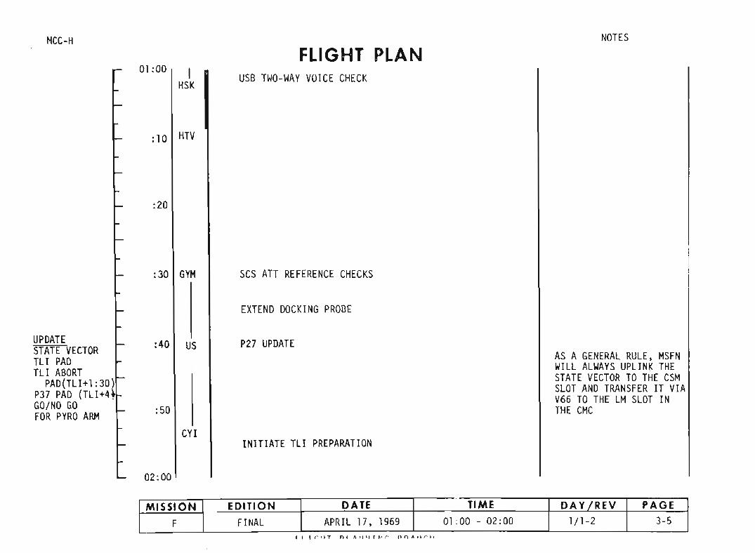
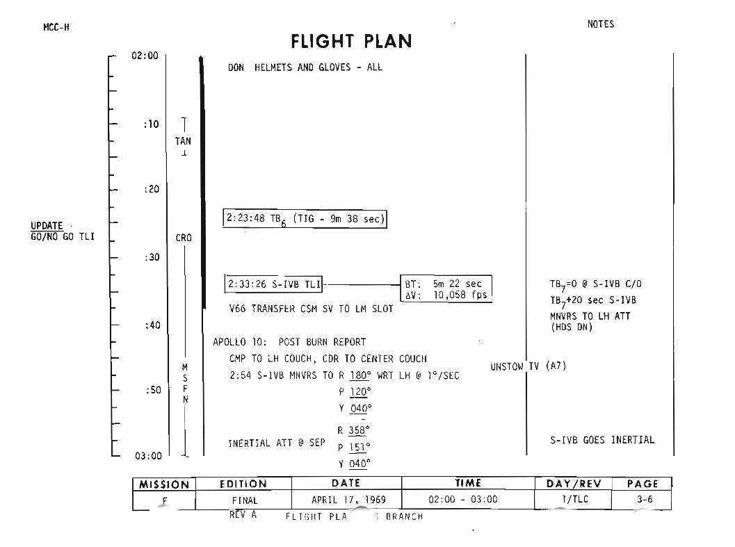
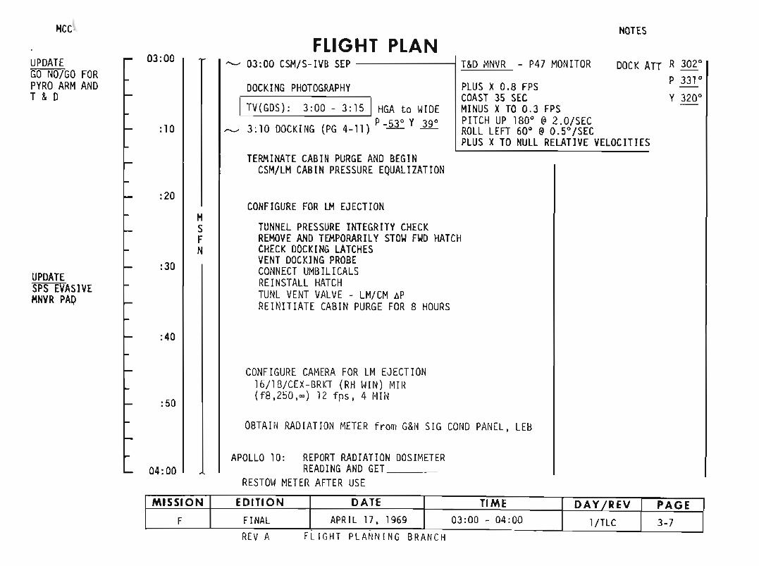
DOCK All
HCCI
UPDATEGO NO/GO FORPYRO ARMANOT & 0
03:00
:10
FLIGHT PLAN--- 03 :00 CSH/S-IVB SEP
DOCKING PHOTOGRAPHY
ITV(GDS): 3:00 - 3: 15 1HGA to WIDE
___ 3:10 DOCK ING (PG 4-11 ) P -~ Y~
TERM INATE CABI NPURGE AND BEG INCSH/LH CAB INPRESSURE EQUAL IZAT ION
NOTES
T&DMNVR - P47 MONITOR
PLUS X0.8 FPSCOA ST 35 SECMINUS XTO 0.3 FPSPITCH UP 180° @2.0/SECROLL LEFT 60° @0.5°/SECPLUS X TO NULL RELATIVE VELOCIT IES
R 302°P 331°Y 320°
UPOATESPS EVASIVEHNVR PAD
:20
:30
:40
:50
HSFN
CONFIGURE FOR LH EJECTION
TUNNEL PRESSURE INTEGRITY CH ECKREMOVE ANDTEMPORARI LY STOW FWD HATCHCHECK DOCKING LATCHESVENT DOCKINGPROBECONNECT UMB ILI CALSREINSTALL HATCHTUNL VENT VALV E - LM/ CMAPREIN ITIATE CAB IN PURGE FOR B HOURS
CONFIGURE CAMERA FOR LMEJECT ION16/1B/ CEX- BRKT (RH WIN ) MIR( f8 , 2 50, ~) 11 fps, 4 MI N
OBTAIN RAD IATION METE R from G&N SIG COND PANEL, LEB
APOLLO 10: REPORT RADIATION DOSIMETER04:00 READ ING ANO GET ___
RESTOWMETER AFTER USE
MISSION EDITION DATE TIME DAY fREV PAGEF FINAL APRIL 17 , 1969 03:00 - 04:00 l/TLC 3-7
REV A Fl lGll T PLA NNING BR ANCH
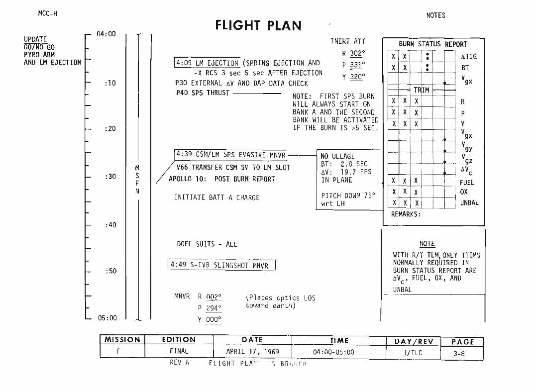
FLIGHT PLANNOTES
INERT ATT BURN STATUS REPORTR 302 0
X X • lI.TlG•NAND P 331° X X • BT•ECTION Y 320° VgxCK -
TR 1MTE: FIRST SPS BURN
X X X RLL ALWAYS START ONNK A AND THE SECOND X X X PNK WILL BE ACTIVATED X X X YTHE BURN IS >5 SEC. Vgx
Vgy- NO ULLAGE VgzBT: 2.8 SEC
t:,.V: 19.7 FPS 6. VcIN PLANE X X X FUEL
PITCH DOWN 75° X X X OXwrt LH X X X L1NBAL
REMARKS:
INITIATE BATT A CHARGE
14:09 LM EJECTION (SPRING EJECTIO-x RCS 3 sec 5 sec AFTER EJ
P30 EXTERNAL 6V AND DAP DATA CHEP40 SPS THRUST NO
WIBABAIF
4:39 CSM/LM SPS EVASIVE MNVR'--
V66 TRANSFER CSM SV TO LM SLOTAPOLLO 10: POST BURN REPORT
MSFN
: 10
:40
:30
:20
04:00
~lCC-H
UPDATEGO/NO GOPYRO ARMAND LM EJECTION
:50
05:00
DOFF SUITS - ALL
MNVR R 002 0
P ~94°
Y 000 0
(Places 0ptics LOStm'la rei ea rth)
NOTEWITH R/T TLM,ONLY ITEMSNORMALLY REQUIRED INBURN STATUS REPORT AREt:,.V , FUEL, OX, ANDcUNBAL
r; BRld·:n.JFLIGHT PLA'REV A
MISSION EDITION DATE TIME DAY /REV PAGEF FINAL APRIL 17, 1969 04:00-05:00 l/TLe 3-8- ._.

MCt~rf NOTES
FLIGHT PLAN05:00 P52 IMU REALIGN(OPTIONAL} 20.000 NM from EARTH
(Option 3 - REFSMMAT) 6h 33m to MCC 1P52 OPT
UPDATE -P37 PAD (TLI N71 :--, --+11 ) P27 UPDATE (ZERO TR~ BIAS) NOS: •ZERO TRN -----BIAS N93:
:30 P23 CISLUNAR NAViGATION-STAR/EARTH HORIZON X •-----(3 MARKS EACH SET) Y •-----SET 1: ALTAIR(40)N Z______.
SET 2: ALTAIR(40}NEH EARTH HORIZON INCORP P23 MARK DATA
M SET 3: ANTARES(33)F FH FAR HORIZON AND UPDATES NH NEAR HORIZONONBOARD STATE VECTORF SET 4: ANTARES(33)F
06:00 NSET 5: PEACOCK(42}N
PTC NOT ESTABLISHEDUNTIL GET 12:00.
:30
07:00
DEACTIVATE PRIMARY EVAPORATORGLY EVAP H20 FLOW - OFFGLY EVAP STH PRESS AUTO - MANGLY EVAP STH PRESS INCR - INCR(5B SEC)
COHM BASIC EXCEPTS-BD AUX TAPE - OFF
POWER OOWN VHF TAPE RCDR FWD - OFFCOMM BASIC CDAST AWAKE ----I CREW MANAr,ES ANT OPS
MISSIONF
EDITIONFINAL
DATE TIMEAPRIL 17. 1969 05:00 - 07:00
FLIGHT PLANNING BRANCH
DAY REV
l/TLCPAGE
3-9

MCC-H
07:00FLIGHT PLAN
NOTES
30,000 NM from EARTH
The PTC REFSMMAT will beuplinked if MCCl can bemade with the PTCREFSMMAT. Otherwise,the PTC REFSMMAT will beuplinked after MCC l asshown at GET 12:00.
:30
MSFN
08:00
FLIGHT PLP lNG BRANCH
MISSION EDITION DATE TIME DAY IREV PAGEF FINAL APRIL 17, 1969 07:00-08:00 l/TLC 3-10
, .,

FLIGHT PLANMCC-H
08:00
:30
-09:80
:30
10:00
MSFN
BATTERY VENT
EVENING MEAL
Fie O2 PURGE
CANISTER A CHANGE(3 to At T to 85)
RECORD BATTERY MANIFOLDPRESSURE (4A) BEFORE,AFTER BATTERY VENT
NOTES
45,000 NM from EA!UM
MISSION EDITION DATE TIME DAY /REV PAGEF FINAL APRIL 17. 1969 08:00-10:00 l/TLe 3-11
FLIGHT PLANNING BRANC~
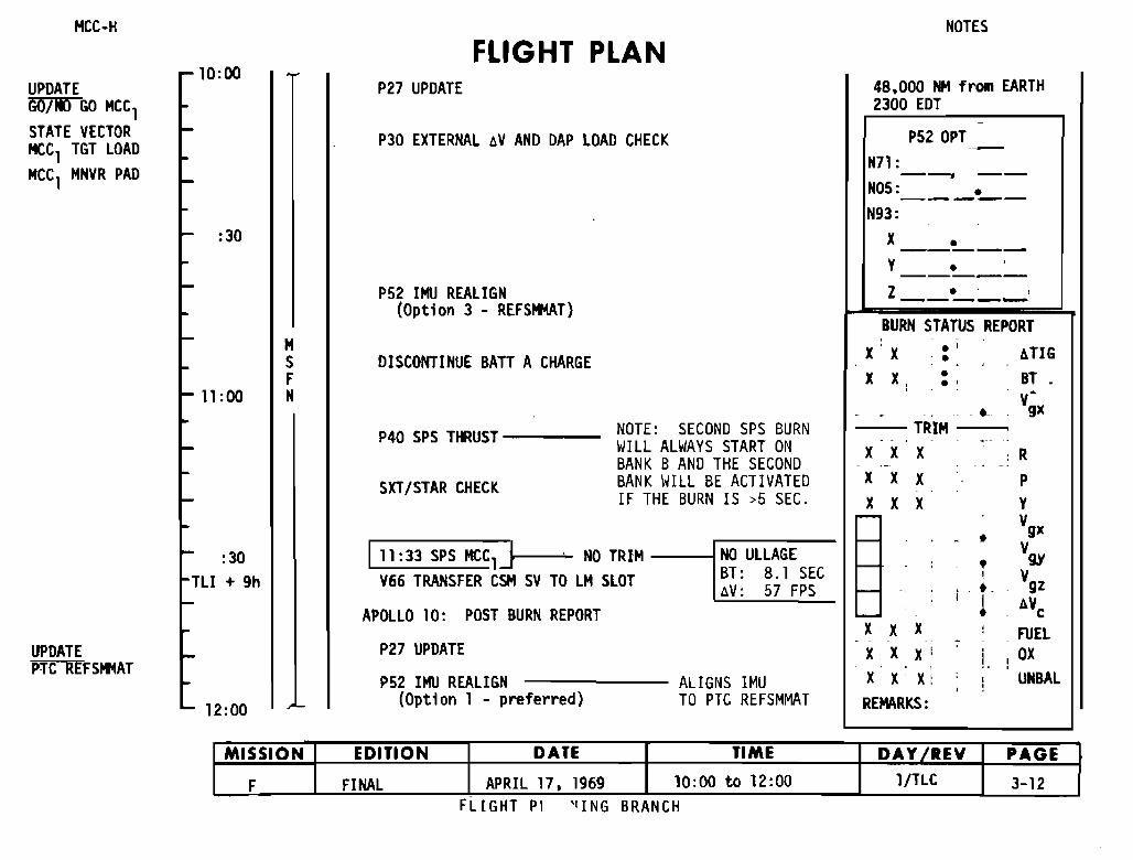
NOTES
FLIGHT PLAN:
P27 UPDATE 48.000 NM from EARTH2300 EDT
P30 EXTERNAL oV ANO OAP LOAD CHECK P52 OPT -N71 :-~ --
N05: •-----N93:
:30 X •-----Y •-----
P52 lHU REALIGN Z •(Opt;on 3 - REFSHMAT) -----
BURN STATUS REPORTM , .:S DISCONTINUE BATT A CHARGE X X • 6TIGF X X: • BT ..'1:DO N Y;x- - ~
P40 SPS THRUST NOTE: SECONO SPS BURN TRIMWILL ALWAYS START ON - - .--
X X X : RBANK B ANO THE SECOND ,- - ,
SXTISTAR CHECK BANK WILL BE ACTIVATED X X X PIF THE BURN IS ,5 SEC. X X X Y
~ Ygxl- •111 :33 SPS HeC1]
.Ygy:30 ND TRIM ND ULLAGE
I- ,:
I + 9h Y66 TRRNSFER CSH SY TD LM SLDT BT: 8.1 SEC ! YgzoV: 57 FPS l- i ' .APOLLO 10: POST BURN REPORT '- ! , oYc
X'X X , FUELP27 UPDATE - .
X: X X' ! OX, .P52 IHU REALIGN ALIGNS IMU X: X X: UNBAL,
12:DD L (Option 1 - preferred) TO PTC REFSMMAT REMARKS:
MISSION EDITION DATE TIME DAY IREV PAGE
F FINAL APRIL 17. 1969 10:00 to 12:00 l/TLC 3-12
1
10 DO
TL
MCC-H
UPDATEPTC REFSHMAT
UPDATEGO/Iil GO MCC1STATE VECTORHeC1 TGT LOADHCC1 HNVR PAD
FLIGHT PI 'lING BRANCH
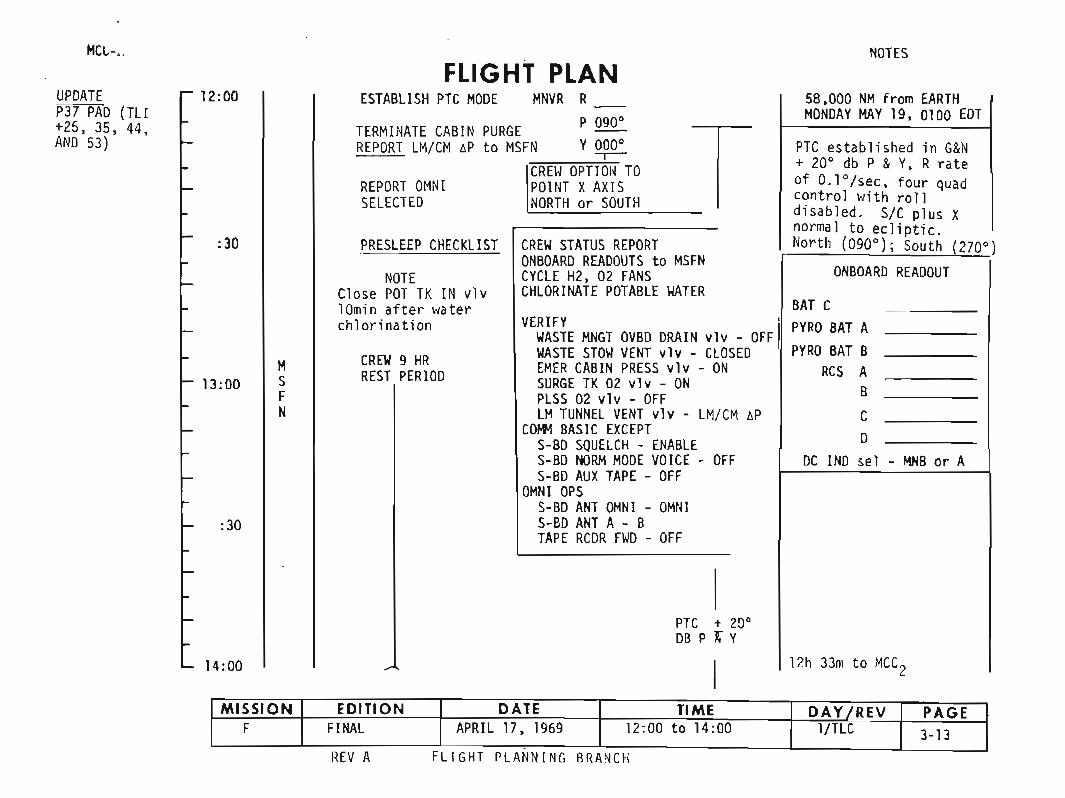
HCl-, NOTES
58,000 NH from EARTHMONOAY MAY 19, 0100 EDT
PTC established in G&N+ 20· db P & Y, R rateof C.lo/sec, four quadcontrol with rolldisabled. SIC plus Xnormal to ecliptic.North (090·); South (270.)
ONBOARO REAOOUT
BAT CPYRO 8AT APYRO BAT B
RCS AB
C
oI-
DC INO sel - ~B or A
CREW STATUS REPORTONBOARD READOUTS to MSFNCYCLE H2, 02 FANSCHLORINATE POTABLE WATER
VERIFY [WASTE HNGT OVBO DRAIN vlv - OFFWASTE STOW VENT vlv - CLOSEOEHER CABIN PRESS vlv - ONSURGE TK 02 vlv - ONPLSS 02 vlv - OFFLH TUNNEL VENT vlv - LM/CM oP
COHM BASIC EXCEPTS-BD SQUELCH - ENABLES-BD NORM MODE VOICE - OFFS-BD AUX TAPE - OFF
OMNI OPSS-BD ANT OMNI - OHNIS-BD ANT A - BTAPE RCDR FWD - OFF
CREW 9 HRREST PERIOD
FLIGHT PLANESTABLISH PTC HODE HNVR R
P 090·TERMINATE CABIN PURGEREPORT LM/CM oP to MSFN Y~
CREW OPTIOH TOREPORT OMNI POINT XAXISSELECTEO NORTH or SOUTH
PRESLEEP CHECKLIST
NOTEClose POT TK IN vlvlOrnin after waterchlorination
HSFN
:30
:30
13:00
12:00UPDATEP37 PAD (TLl+25, 35, 44,AND 53)
PTe + 20°DB P X Y
14:00 12h 33m to MCC2
FLIGHT PLANNING BRANCHREV A
MISSION EDITION DATE TIME DAY /REV PAGEF FINAL APRIL 17, 1969 12:00 to 14:00 l/TLC 3-13
.
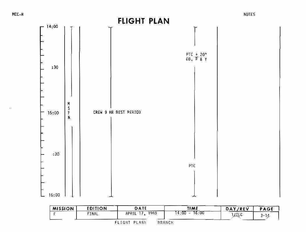
MCC-H
14:00
: 30
HS
15:00 FN
:30
16:00
FLIGHT PLAN
CREW9 HR REST PERIOD
rPTC + 20·OS , P & Y
PTC
NOTES
MISSION EDITION DATE TIME DAY fREY PAGEF FINAL APRI L 17 ,1 969 IO:UU - 16: uu
~C 3-1)FLIG HT Pl AII ~ SRArlCH

16:00FLIGHT PLAN
NOTES
PTC. 20·DB.-P & Y
17:00
M5
18:00 FN
CREW 9 HR REST PERIllO
19:00
PTC
20:00
fLIGHT PLANNING BRANCH
MISSION EDITION DATE TIME DAY/REV PAGE
F FINAL APRIL 17. 1969 16:00 - 20:00 l/TLC 3-15- .

MCC-HFLIGHt PLAN
NOTES
20:0090,000 NM from EARTH
PTC + 20·DB, if & Y
:30 CREW 9 HR REST PERIOD
MS
21:00 FN
:30 END REST PERIOD
BREAKFAST PTC
MONDAY, MAY 19,)030 EDT5h to MCC212h 30m to next restperiod
CANISTER B CHANGE(4 TO B, !TO B5)
22:00
FLIGHT PLA' -"G BRANCH
MISSION EDITION DATE TIME DAY fREV PAGEF FINAL APRIL 17, 1969 20:00 - 22:00 l/TLC 3-16
-. ~
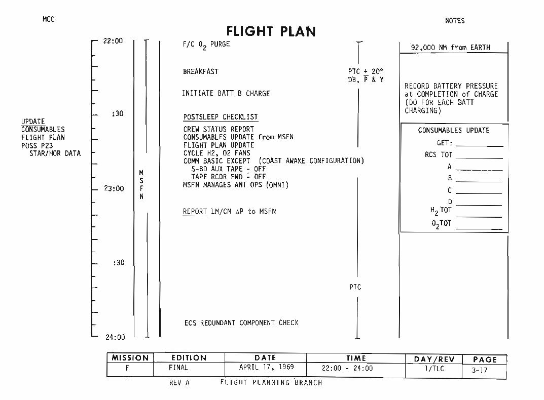
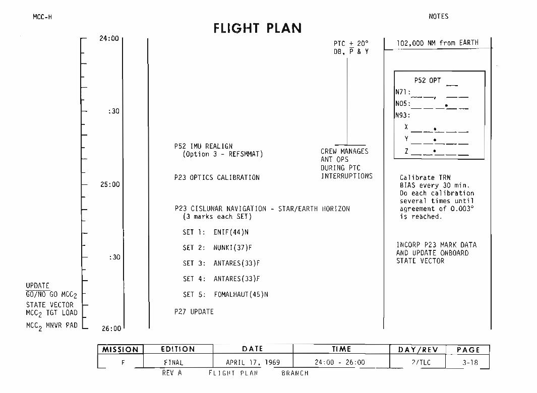

P30 EXTERNAL 6V AND DAP DATA CHECK
FLI GHT PLAN
ITV( GDS) : 27:15 - 27:301HGA to NARROW
P40/ 41 SPS/ RCS THRUST
SXT STAR CHECK
/
NOTES
108,000 NM from EARTH1500 EDT
8URN STATUS REPORT
X X • 6TIG•X X • BT•
VgxTR 1M I
X X X RX X X PX X X Y
.. VgxI Vgy
Vgz6Vc
X X X FUELX X X OXX X X UNBAL
RE MA RKS :
After comple t ion of t hePTC mode test at +30° DBa decis ion wil l be madereal t ime on t heoperati on al DB for PTC(! 20° or + 30°) androll rate TO.l or 0.3° sec
UNSTOW, SETUP TV
RE-ESTABLISH [email protected]°/SEC ROLL RATE ,DI SABLE ROLL JETS.10m LATER GO TO+ 30· DB. MAINTAIN aMINIMUMOF 4 HRS. (Pg 4-14)
REPORT OMN I SE LECTED
NOON MEAL
MNVR RP 090·Y 000·
126:33 MCC2] DO NOT TRIM
V66 TRANSFER CSM SV TO LM SLOT
APOLLO 10: POST BU RN REPORT
MSFN
28:00
:30
27:00
26:00
:30TLI + 24
MCC-H
MIS SION EDITIO N DATE TIME DAYf REY PAGEF FINAL APRIL 17. 1969 26:00 - 20 :00 2/ TLC 3-19
REV A FLIGI1T PLANNI NG BRANCH

S-BANo REFLECTIV ITYTEST
MNVR R P Y HGA P Y
NOTETHE S-BANo REFLECTIV ITY TE STWITH THE CSM/ LMHAS BEEN DE LETED .THE TEST MA Y BE SCHEDULED REALTIME WITH THE CSM DURING TEC.
TEST NO2 3
I~_1 00 .200 _30·
I ,,;;. I 1 ;: ;;. 1360·P · 10° _200 _300
330· 3400
1. MNVR HGA METER
2. SET HGA CNTLLLl..EQ:
3. HI GAINANT BEAM - WI DEHI GAI N ANT TRACK- MANUAL
4. WHEN HGA METER COMPARES TO HGA CNTLHI GA IN ANT TRACK- AU TOHI GAIN ANT BEAM - NARROW
5. RECORD I TEsT NO. I1 1 2 1 3
COMMBAS IC EXCEPTS-Bo RANGING - OFF
GO TO HGA OPS, VERI FY LoCXATT HOLD 0. 5· dbDO STEPS 1-6 TEST 1
HGA METER ~I I /==.j%SIGNAL
6. EVALUATE VOICE COHMREPEAT STEPS 1-6 TEST 2REPEAT STEPS 1-6 TEST 3
7. RETURNTO COMMCOAST AWAKES- BD· AUXTAPE - OFFTAPE RCDR FWD- OFF
FLI GHT PLANNING BRANCH
MISSION EDITION DATE TIME DAY/REV PAGEF FINAL APRIL 17 , 1969 26: 00 - 20:00 2/ TLC 3- 19A
nl:"11 1\ ,
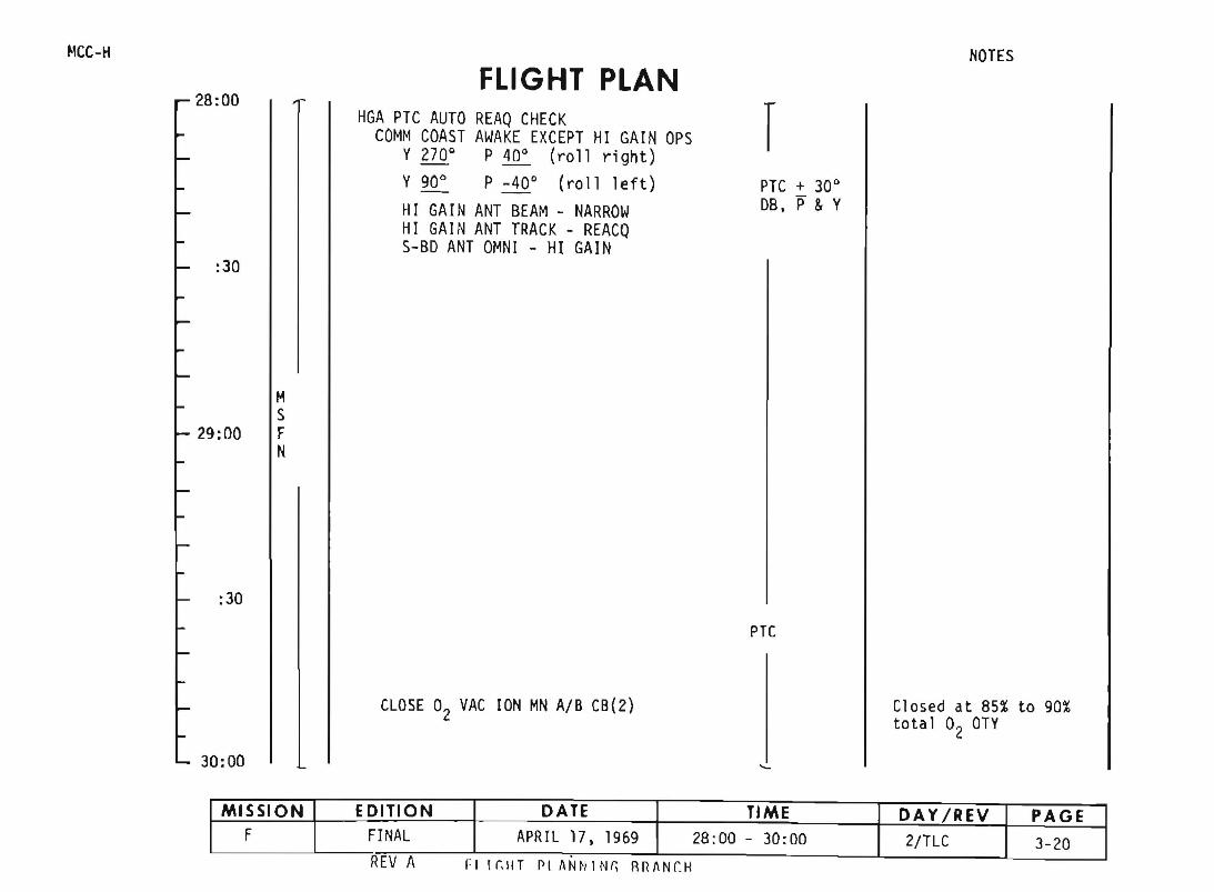
~'CC-H
28:00
:30
FLIGHT PLANHGA PTC AUTO REAQ CHECK
COMM COAST AWAKE EXCEPT HI GAIN OPSY 270 0 P 40 0 (roll right)- -Y 90° P -40 0 (roll left)
HI GAIN ANT BEAM - NARROWHI GAIN ANT TRACK - REACQS-BD ANT OMNI - HI GAIN
rPTe + 30 0
DB, P & Y
NOTES
MS
29:00 FN
:30
PTe
CLOSE 02 VAC ION MN AlB C8(2) Closed at 85% to 90%total 02 OTY
30:00
REV A fl I (;IIT rl ANN 1Nr; RRI\Nr.H
MISSION EDITION DATE TIME DA YjREV PAGEF FINAL APRIL 17, 1969 28:00 - 30:00 2/TlC 3-20
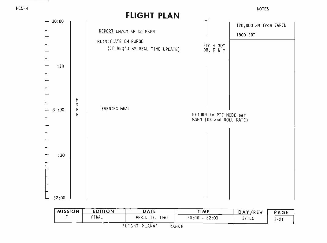
MCC-H
30:00FLIGHT PLAN
RE PORT LM/ CM, P to MSFN
RE IN ITI ATE CMPURGE(IF REQ 'D BY REAL TIME UPDATE )
rPTC + 30°DB , l' &Y
NOTES
120 ,000 NM f rom EARTH
1900 EDT
:30
31:00
MSFN
EVE NING MEALRETURN to PTC MODE perMSFN (DB and ROLL RATE)
:3D
32:00
RArICHFLlGltT PLA NN '
MISSION EDITION DATE TIME DA YIR EV PAGEF FINAL AP RIL 17, 1969 30:00 - 32 :00 2/TLC 3-21-

MCL
32: 00
:30
NOTESfliGHT PLAN
122.000 NM from EARTH
PTC
1.r------
UPDATEGO/ NO GOSTATE VECTORLUNAR FLY BY PAD
33:00
:30
MSFN
PRESLEEP CHECKL IST
P27 UPDATE
CREWSTATUS REPORTONBOARDREADOUTS to MSFNCYCLE H2. 02 FANSCHLORI NATE POTABLE WATERVERIFY
WASTE MNGT OVBD ORAI Nvlv - OFFWASTE STOWVENT vlv - CLOSEDEMER CABIN PRESS vl v - BOTHSURGE TK 02 vl v - ONPLSS 02 vlv - OFFLMTUNNEL VENT vlv - LM/ CM 6P
COHM BAS IC EXCEPTS-BD SQU EL CH - ENABLES-BD NORMMODE VOI CE - OFFS-BDAU XTAPE - OFF
ONBOARDREADOUT
BAT CPYRO BAT A _PYRO BAT B _
RCS A _B _
C _
0 _
DC IND SEL to MNA or MNB
GO TO HGA OR CONTINUE OMN I OPS PER MSF~
34:00
CANISTER A CHANGE(5 to A. 3 to B5 )
FIC O2 PURGE
III GAINOPSY270 P40 (rol l right )Y90 P-40 (rol l left )HI GA INANT BEAM - NARROWIII GAIN ANT TRACK- REACQS-BD ANT OMNI - HI GAI N
OMN I OPSS-BD ANT OMN I - OMN IS-BD ANT A - BTAPE RECDR FWD - OFF
MISSION EDITION DATE TIME DAY / REV PAGEF FINAL APRIL 17. 1969 32:00 - 34:uu 2/ TLC 3-22
RE VA FLIG HT PLA NN IN G BRANCH
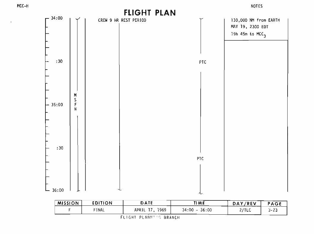
MCC-H
34:00FLIGHT PLAN
CREW 9 HR REST PERIOD
NOTES
130 ,000 NM f rom EARTH
MAY 19 , 2300 EDT
19h 45m to MCC3
: 30 I I I I PTC
MS
35:00 I FN
: 30
PTC
36:00
MISSION EDITION DATE TIME DAY tREY PAGEF FINAL APRIL 17. 1969 34:00 - 36: 00 2/ TLC J-23
fLI GHT PLAN N " ' ~ BRA NCH

MCC NOTES
FLIGHT PLAN36:00 i
PTC
38:00
SCREW 9 HR REST PERIOD39:00 F
N
40:00
PTC4U 00
37:00
MISSION EDITION DATE TIME DAY REV
M
42:00
F FINAL APRIL 17, 1969 36:00 - 42:00 2/TLC
FLIGHT PLANNING BRANCH
PAGE3-24
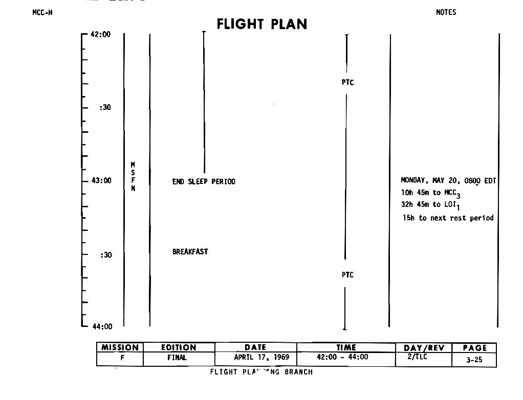
MCC-H NOTES
FLIGHT PLANr 42:00
PTC
:30
- 43:00
MSFN
END SLEEP PERIOD
BREAKFAST
MONDAY, MAY 20, 0800 EDT
10h 45m to MCC3
32h 45m to LOI1
15h to next rest period
PTC
- 44:00
MISSION EDITION DATE TIME DAY REV PAGEF FINAL APRIL 17, 1969 42:00 - 44:00 2/TLC 3-25
FLIGHT PLPV ' NG BRANCH

NOTES
155,000 I~ from EARTH IFLIGHT PLAN
PDSTSLEEP CH ECKL IST
REV A FLIGHT PL AN N I N~ BRANCH
CREWSTATUS REPORT CONSUMABLES UPDATECONSUHABLES UPDATE from MSFN PTCFLIGHT PLAN UPDATE GET:CYCLE HZ, OZ FANS RCS TOTCOMM BASIC EXCEPT
S-BD AU XTAPE - OFF ATAPE RCDR FWD - OFF B:30 MSFNMANAGES ANT OPS
CPZ7 UPDATE 0
HZTOT
OZTOTP5Z IIt l REALIGN
M 10pti on 3 - REF SMHAT)S CHECKCELESTIAL BODYOPTION)
45:00 FN
HNVR R-P 090'-Y000'-
REPORT OMN I SELECTED:30 ]HZ PURGE LINE HTRS - ON P5ZOPT
IPTC - IN71:- - . - -NOS: •---- -N93:
CANI STER B CHANGEX(6 to B, 4 to B5 ) •- - - - -Y •46:00 --- - -- Z •- - ---
MISSION EDITI ON DATE TIME DAY I REV PAGEF FINAL APRI L 17, 1969 44 :00 - 46:00 21TLC 3-Z6
_._ --'
44:00
f1CC-1
UPDATESTATE VECTOR
UPDATECDN SUMABLESFLIGHT PLAN

HCC-H
46: 00
: 30
47:00
:30
48: 00
HSFN
FLIGHT PLAN
FIC O2, H2 PURGE
NOON HEAL
rPTC
PTC
NOTES
7h 45m to MCC3
MISSION EDITION DA TE TIM E DAY/R EV PAGEF FI NAL APRIL 17. 1969 46:00 - 48:00 2/ TLC 3- 27
Fll GHT PLAt BRANCH

48:00FLIGHT PLAN
NOTES
165,000 NM from EARTH
ECS REOUNDANT COMPONENT CHECK
:30PTC
49:00
MSFN
:30
PTC
50:00
FLIGHT PLANNING BRANCH
MISSION EDITION DATE TIME DAY IREV PAGEF FiNAl APRIL 17, 1969 48:00 - 50:00 3/TLC 3-28
.- .

MCC-H NOTES
FLIGHT PLANr 50:00
PTC
-- 51:00
MSFN
PTC
52:00 t
MONDAY, MAY 201500 EDT
MISSION EDITION DATE TIME DAY REV PAGEF FINAL APRIL 17, 1969 50:00 - 52:00 /TL -
FLIGHT PLANr BRANCH
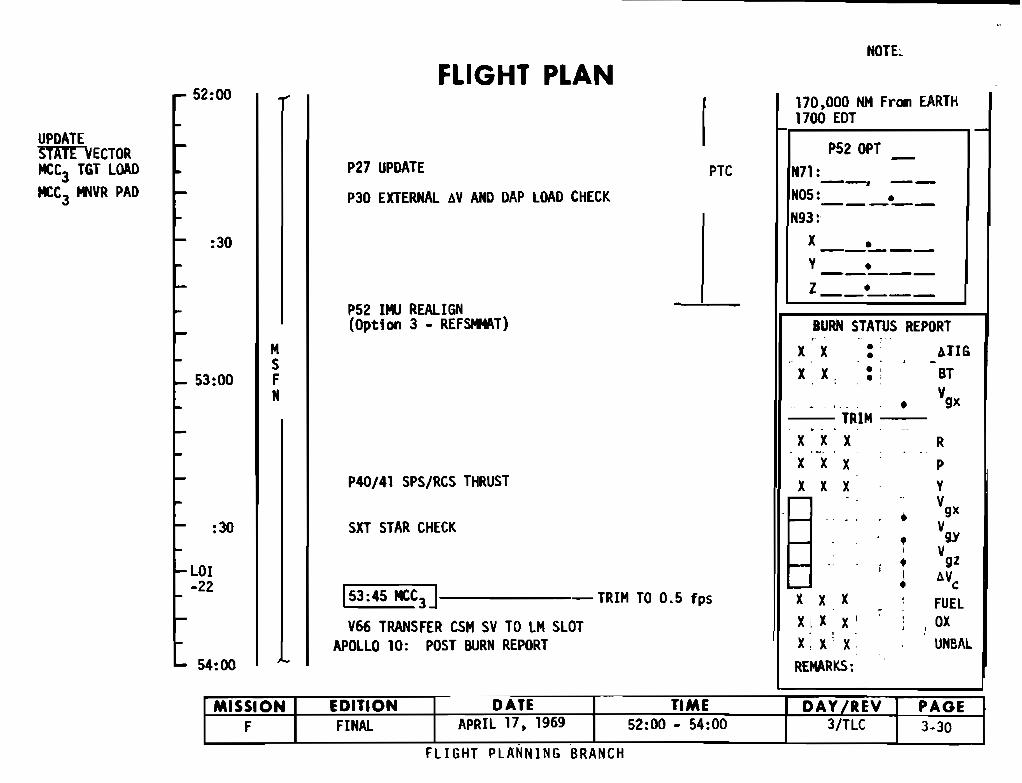
NOTE:
FLIGHT PLANr- 52:00
L
170,000 NM Fran EARTH1700 EDT
UPDATESTATE VECTOR P52 OPTMCC3 TGT LOAD
MCC3 MNVR PAD
P27 UPDATE
P30 EXTERNAL CV AND DAP LOAD CHECK
PTC N71: __
N05:
N93:--
:30 XY
Z
I
P52 IMU REALIGN(Option 3 - REFSMMAT) BURN STATUS REPORT
MS
x X _.•._
.ATIG
L_ 53:00 FN
X X .'
TRIM
BT
Vgx
P40/41 SPS/RCS THRUST
X
X
x
X X
X x
X x
P
Y
Vgx:30 SXT STAR CHECK ♦ V
♦ 9Y
♦ VgzLOI + Av-22
c
53:45 MCC TRIM T 0 53 - .O fps x X X FUEL
V66 TRANSFE R CSM SV TO LM SLOT X X x ox
L- 54:00APOLLO 10 : POST BURN REPORT X. x x
REMARKS:
UNBAL
MISSION EDITION DATE TIME DAY/REV I PAGEF FINAL APRIL 17, 1969 52:00 - 54:00 3/TLC 3-30
FLIGHT PLANNING BRANCH

MCC-H NOTES
r 54:00
55:00
:30
56:00
MSFN
FLIGHT PLANEVENING MEAL
TV (GDS ) 54:00 - 54:15
HGA to NARROW
PTC
PTC
1
1900 EDT176,000 MN from EARTH39,000 NM from MOON
MISSION EDITION DATE TIME DAY REV PAGEF FINAL APRIL 17, 1969 54 :00 - 56:00 3/TLC 3-31
FLIGHT PLAT G BRANCH
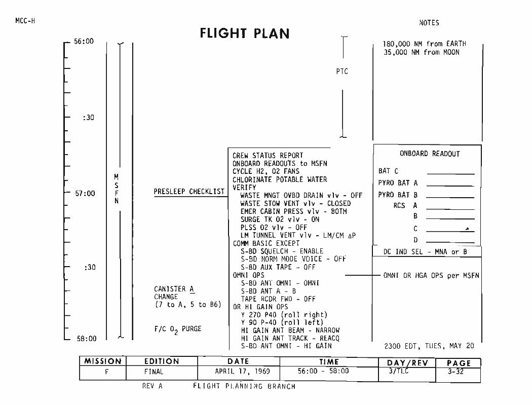
EARTH
NOTES
2300 EDT, TUES, MAY 20
160 000 NMf, rom35 ,000 NMfrom MOON
C
-ONBOARD READOUT
BAT CPY RO BAT A
- OFF PYRO BAT BED RCS AH B
C •~P 0- ..
DC INDSEL - MNA or BF
OMNI OR HGA OP S per MSFN
TPT
CREWSTATUS REPORTONBOARDREADOUTS to MSFNCYCLE H2, 02 FANSCHLORINATE POTABLE WATERVERIFY
WASTE MNGT OVBD DRA IN v1vWASTE STOW VENT v1v - CLDSEMER CABIN PRESS v1 v - BOTSURGE TK02 v1v - ONPLSS 02 vlv - OFFLM TUNN EL VENT v1v - LM/ CM
COHM BASI C EXCEPTS-BD SQUE LCH - ENAB LES-BD NORM MODE VOICE - OFS-BDAUXTAPE - OFF
OMNI OPSS-BDANT tlMNI - OMNIS- BDANT A - BTAPE RCDR FWD - OFF
OR HI GAINOPSY270 P4D (r oll ri ght)YgO P-4D (rol l lef t )HI GAIN ANT BEAM - NARROWHI GAINANT TRACK - REACQS- BDANT OMNI - HI GAI N
FLI GHT PLAN
FIC O2 PURGE
PRE5LEEP CHECKLIST
CANISTER ACHANGE -(7 to A, 5 to B6)
MSFN
:30
:30
5B:00
57:00
56 :00
ftCC-H
MISSION EDITIO N DATE TI ME DAY f REV PAG EF FINAL APRIL 17, 1969 56:00 - 5B:00 3/ TLC 3-32
REV A FLl nur PI.A Nfl l NG BR ANCH
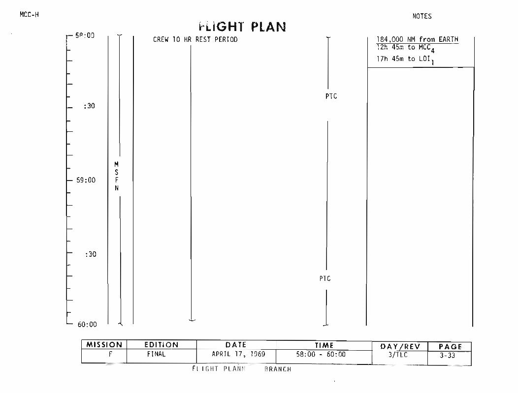
MCC-H
r 5P ;O:lH.iGHT PLAN
CREW10 HR REST PE RI OD
NOTES
184.000 11M f rom EARTHW i 45::: to MCC417h 45m to LOl l
PTC: 30
MS
59:00 I FN
:30
PTC
60:00 1BRANCIIFll r.IIT PLA II I'
MISSION EDITI O N DATE TIME DAY f REY PAGEF FINAL APR IL 17 . 1969 58:00 - 60:00 3/TLC 3-33
. - - - --
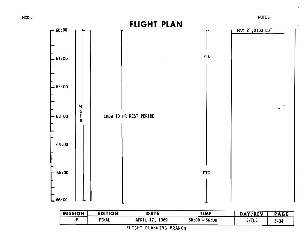
MCC-,, NOTES
FLIGHT PLANr 60:00
PTC
r MAY 21,0100 EDT
`- 62:00
`- 63:00
MSFN
CREW 10 HR REST PERIOD
I- 64:00
- 65:00
L 66:00
PTC
iMISSION EDITION DATE TIME DAY REV PAGE
F FINAL APRIL 17, 1969 60:00 -66:00 3/TLC 3-34
FLIGHT PLANNING BRANCH

MCC-H
66:00FLIGHT PLAN
INOTES
198.000 NM from EARTH
PTC
:30
67:00
MSFN
CREW 10 HR REST PERIOD
:30
PTC
68:00END REST PERIOD 1
NG BRANCHFLIGHT PL,
MISSION EDITION DATE TIME DAY fREV PAGEF FINAL APRIL 17. 1969 64:00 - 68:00 3/TLC 3-35
----
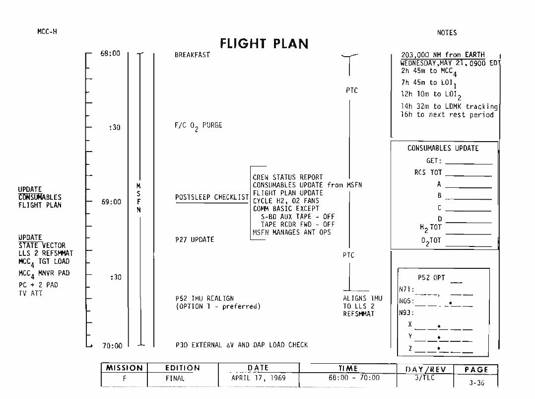
PZ7 UP DATE
PTC
CREWSTATUS REPORTCONSliMABLES UPDATE fromMSFN
POSTSLEEP CHECKL IST FLI GHT PLANUPDATE_______ CYCLE HZ, OZ FANSCO,'" BAS IC EXCEPT
S-BD AU XTAPE - OFFTAPE RCDR FWD - OFF
MSFN MANAGES ANT OPS
A T
NOTES
Z03, 000 NM from E R H IWEONE SOAY,MAY Zl,0900 EDZh 4Sm to MCC47h 45m to LOlllZh 10m t o LOIZ14h 3Zm to LDMK tra cking16h to next rest per Iod
CONS UMABLES UPOATEGET:
RCS TOTABC0
HZTOT
OZTDT
PSI OPT -N7l :- - , --NOS: •- - - - -N93 :
X •- - - - -Y •-----Z •- - ---
PTC
ALIGNS IMUTO LL S IREFSI+IAT
T
L
P30 EXTERNAL aVAND DAP LOAD CHECK
FLIGHT PLANBR EAKFAST
FIC Oz PURGE
PSI IMU REALIGN(OPTION 1 - prefer red)
:30
:30
70 :00
MS
69:00 FN
6B:00
HCC -H
UPDATESTATE VECTORLLS Z REFSI+IATHCC4 TGT LOAOHCC4 HNVR PAOPC t Z PADTV All
UPDATECOHSOOBLESFLIGHT PLAN
M I SSIO N EDITI ON DA TE TIME OAY f REV PAGEF FINAL APRIL 17,1969 68:00 - 70:00 3/TLC
3-3 6- - - --- --- - - - --. --- -

FLIGHT PLANMCC-H
UPDATEKKK.... LOll'
MN VR PADTEll PADTEI 4 PAD
70:00
:30
LOI - 5h
71:00
:30
72:00
MSFN
CANISTER B CHANGE(B TO B;-6 TO B6)
P40/P41 SPS/RCS THRUST
sXT STAR CHECK
170:45 MCC4 I
V66 TRANSFER CSM SV TO LM SLOTAPOLLO 10: POST BURN REPORT
TV UPDATER HGAP PY Y
UN ST OW. SETUP TV
ECS REUUNDANT COMPON ENT CHECK
TRIM X to 1 fps
NOTE:A11 at t itudes int he t imel ine arei nertial wr t LOGsite 2 REFSMMAT.
NOTES
BURN STATUS REPORT
X X • ATIG•X X • BT•
VgxTRIM
X X X . RX X X PX X X Y
I-- .!-Vgx
1 VgyVgz.. AVe
X X X FUELX X X OXX X X UNBALREMARKS:
MISSION EDITION DATE TIME DAY/REV PAGEF FINAL APRIL 17. 1969 70:00 - 72:00 3/TLC 3-37
REV A FLI GH T PU IG BRANC H
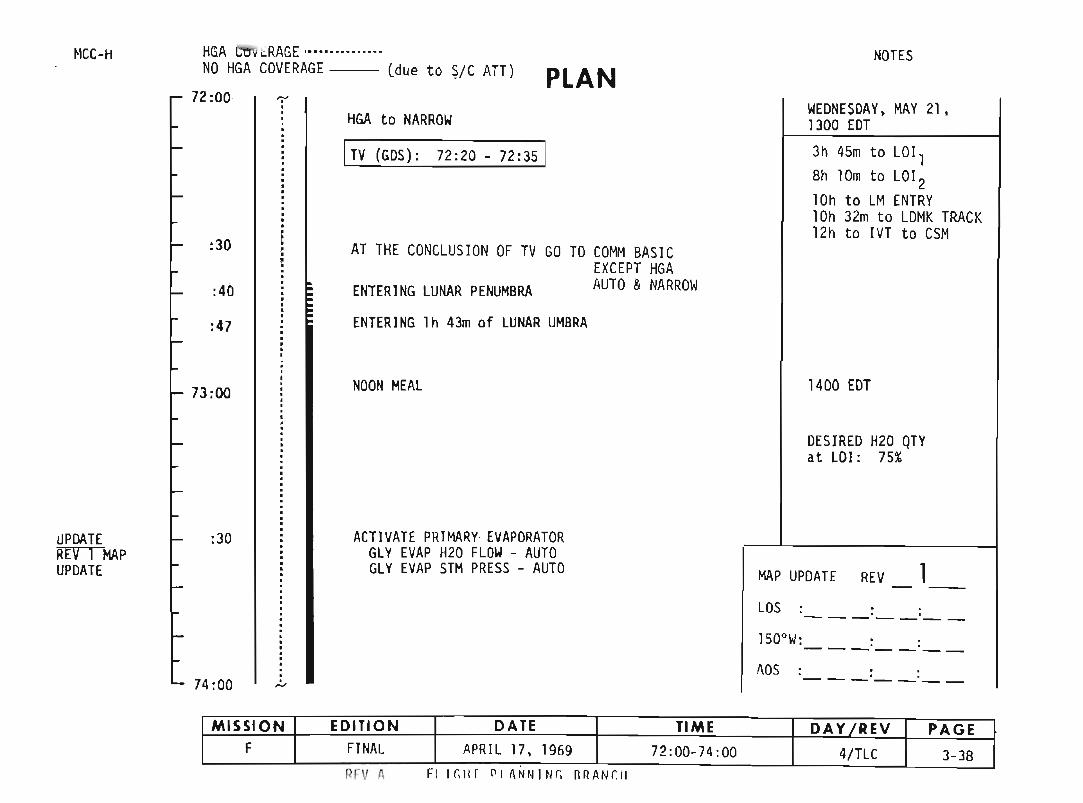
ITV (GDS) : 72:20 - 72:35 1
72:00HGA to NARROW
HGA Cll"i "RAGE ·········..·•·NO HGA COVERAGE (due to ~/C ATT)
3h 45m to LOl lBh 10m to LO l210h t o LM ENTRY10h 32m t o LOMK TRACK12h to IVT to CSM
NOTES
WEDNESDAY, MAY 21,1300 EDT
PLAN
ENTERING LUNAR PENUMBRA
AT THE CONC LUS IONOF TV GO TO COMM BAS ICEXCEPT HGAAUTO &NARROW
:30
:40
fICC-H
:47 ENTER ING Ih 43m of LUNAR UMBRA
73: 00 NOONMEAL 1400 EDT
DES IREDH20 QTYat LOI : 75%
~PllAT E
REV 1 HAPUPDATE
:30 ACT IVATE PR IMARY· EVAPORATORGLY EVAP H20 FLOW- AUTOGLY EVAP STMPRESS - AUTO MAP UPDATE REV 1- -
LOS : ::- - - -- - -1500W : : :----- - -
74:00AOS . .. .----- - -
MISSION EDITION DATE TIME DAY/REV PAGEF FINAL APR IL 17, 1969 72:00- 74 :00 4/ TLC 3-38
I?rv " FI ,r.", PI IHlt l I Nt. RRArIC H

NOTES
FLIGHT PLAN~ :uu ...
P52 IMU REALI GN 210,000 NM from EARTH(Option 3 - REFSMMAT) WEDNESDAY, MAY 21,
1500 EDTP27 UPDATE
P52 OPT._-P30 EXTERNAL 6V AND DAP DATA CHECK N71:- - , --MNVR R 3560 and CK LOl l BURN ATT N05 : •-----
:30 P 2320 (SXT STAR CHECK) N93 :
Y 3400 X •- - - -- --:40 Y •F - - ---
Z •_ ._--_.-L BURN STATUS REPORTOMN I
X X • 6TIG•; :00 X X • BT•V9x
n 1MX X X R
P40 SPS THRUST X X X PX X X Y
NOTE : IF NO DSE MOTION @LOS Vgx:30 GO CMD RESET then NORM
:38Vgy- LOI , OV ERBURN CRITER IA: 10 SEC Vgz
1 75:45 LOl l 1- - NO TR IM6Vc
~~~*fjlNO ULLAGEBT: 6m 02 SEC X X X FUEL~i·*:#..
2974 FPSV66 TRANSFER CSM 6V: X X X OXSV TO LM .SLOT 60 x 170
X X X UNBAL6:00 HOLD CUTOFF ATT UNTIL 76:00REMARKS :
MISSION EDITION DATE TIME DAY/REV PAGEF FINAL APRIL 17 , 1969 74 :00-76:00 4/1 3-39
7
7
7
,/@:'\1f~:
HCC-
UPDATESTATE VECTORLO ll TGT LOADLOll MNVR PAD
UPDATEiillfROGO LOll
REVA FLI GHT PLA NNIN G BRAN CH
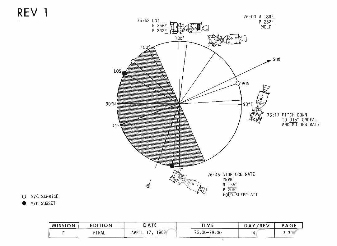
76: 00 R lliQ:P liE.HOLD
SUN
76: 17 PI TCH DOWNTO 3150 ORD EALANDGlY ORB RATE
ADS
~: 76:45 STOP ORB RATE~~~ MNVR 0
:.- V(~ . /; R 135
.~VJJ ~O~~~~LEEP ATT
J
75 :52 LOI ~.<f1R 356
0
~'<tJ
P 232
0
~.. ,,<> 1"180
0{ •I 1____
900 W
o SI C SUNRISE
• SIC SUNSET
REV 1
MISSION I EDI TION DATE TIME DAYf REY PAGE IF FI NAL APR IL 17, 1969~ 76 :00-78 :00 4 ~ 3-39Jf
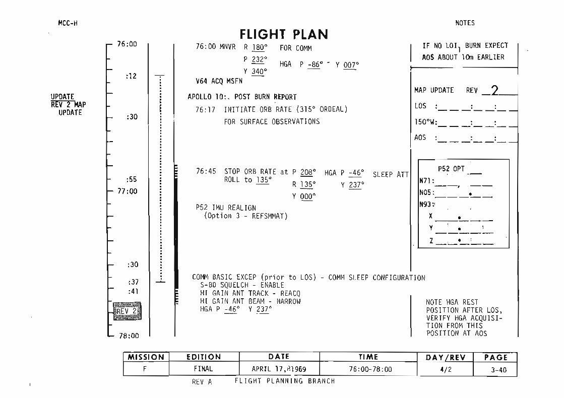

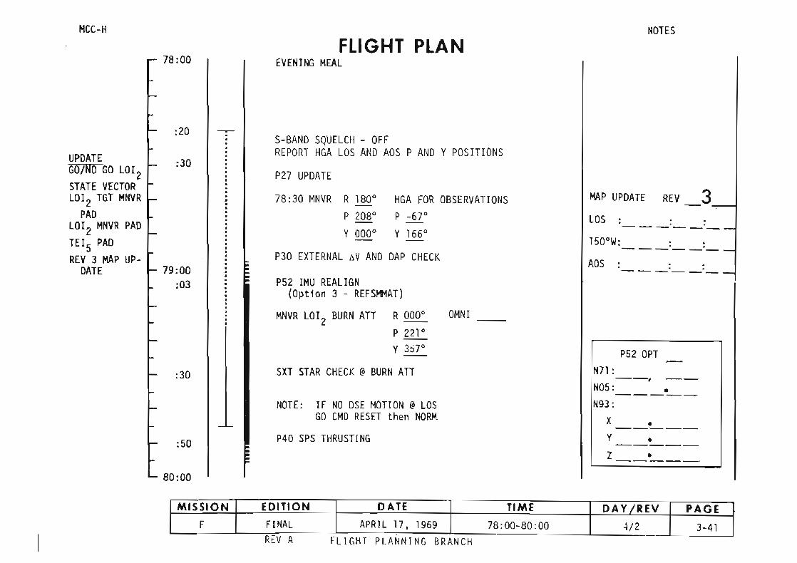
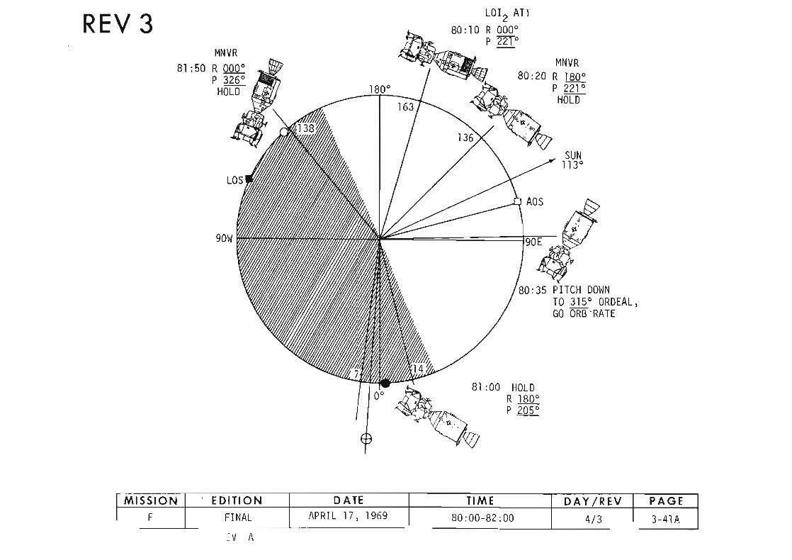


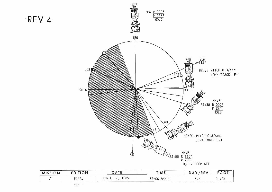

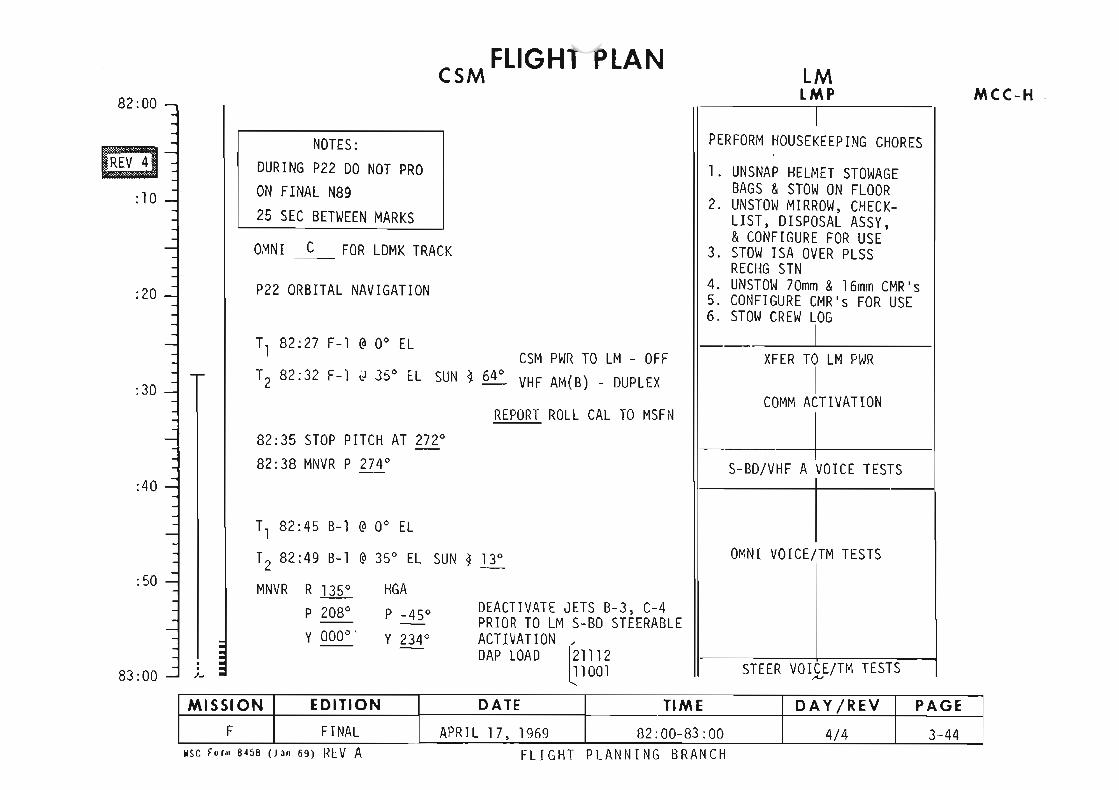
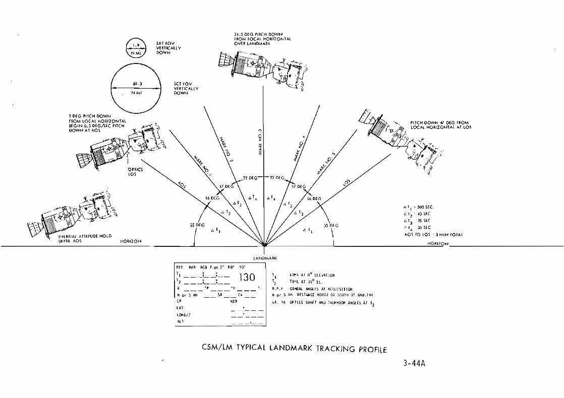


~lCC·
86:00
:10
:24
:30
87:00
:30
:36
:45
88:00
FLIGHT PLAN
CREW 8 HR REST PERIOD
SLEEP An
SLEEP ATT
NOTES
MISSION EDITION DATE TIME DAY fREV PAGE
F FINAL APRIL" 17. 1969 86:00 - 88:00 4/6 3-48
FLIGHT PLANNlNG BRANCH
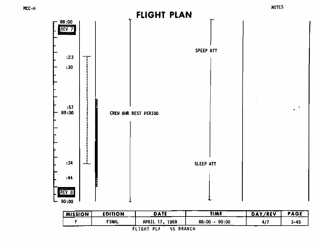
HCC-H
88:00
B:JFLIGHT PLAN
NOTES
SPEEP ATT:23
:30
:5789:00 CREW 8HR REST PERIOD
:34 SLEEP ATT
:44
REV 8
90:00
FLIGHT PL' ~G BRANCH
MISSION EDITION DATE TIME DAY/REV PAGE
F FINAL APRIL 17. 1969 88:00 - 90:00 4/7 3-49-

90:00
:20
:30
:5691 :00
:33
:42
m92:00
-
FLIGHT PLAN
SLEEP ATT
CREW 8HR REST PERIOD
SLEEP ATT
NOTES
MISSION EDITION DATE TIME DAY fREV PAGEF FINAL APRIL 17. 1969 90:00 - 92:00 4/8 3-50
FLIGHT PLANNING BRANCH
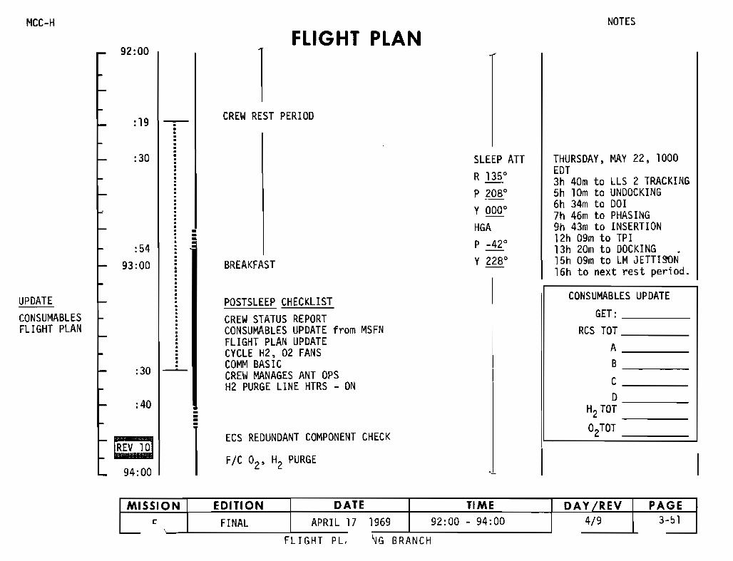
~lCC-H
92:00FLIGHT PLAN
1
NOTES
:19 CREW REST PERIDD
:30
:5493:0D
•--BREAKFAST
SLEEP ATTR 1350
P 2080
Y ODO°HGAP _42 0
Y 2280
THURSDAY, MAY 22, 1000EDT3h 4Dm to LLS 2 TRACKING5h lDm to UNDDCKING6h 34m to DOl7h 46m to PHASING9h 43m to INSERTION12h D9m to TPI13h 20m to DOCKING .15h 09m to LM JETTISON16h to next rest period.
UPDATECONSUMABLESFLIGHT PLAN
:30
:40
[REV @94:00
•--
1
POSTSLEEP CHECKLISTCREW STATUS REPORTCONSUMABLES UPDATE from MSFNFLIGHT PLAN UPDATECYCLE H2, 02 FANSCDMM BASICCREW MANAGES ANT OPSH2 PURGE LINE HTRS - ON
ECS REDUNDANT COMPONENT CHECK
FIC O2, H2 PURGE
CONSUMABLES UPDATEGET: ----
RCS TOT _A _B _C _
DH2TOT----
°2TOT
~G BRANCHFLIGHT PL,
MISSION EDITION DATE TIME DAY/REV PAGEc FINAL APRIL 17 1969 92:00 - 94:00 4/9 3-51
L-


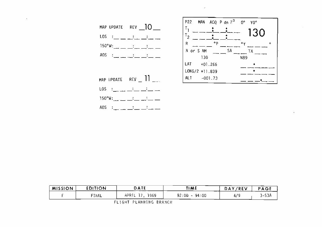

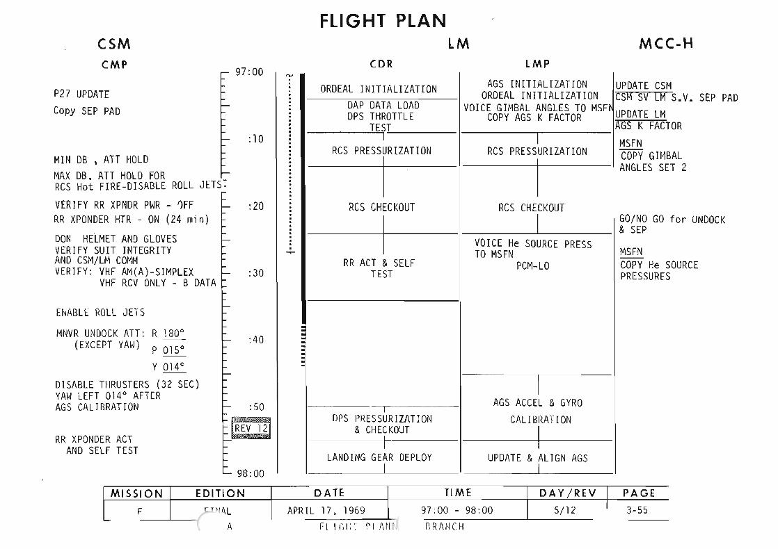


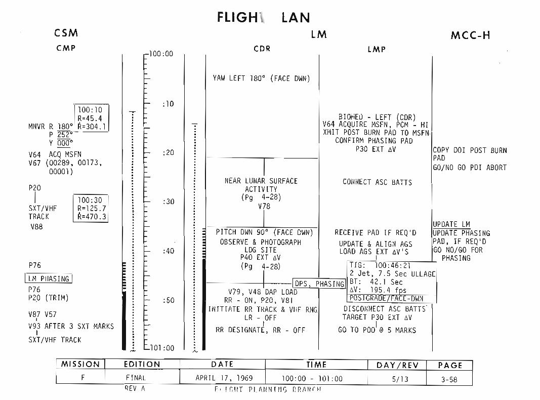
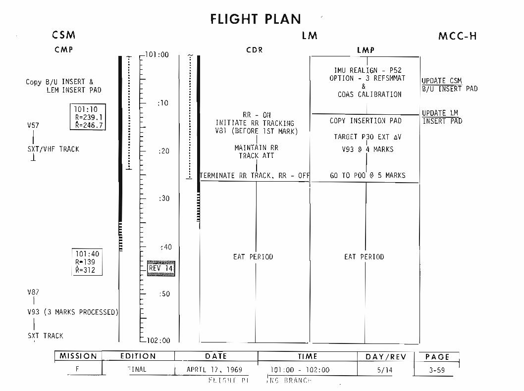


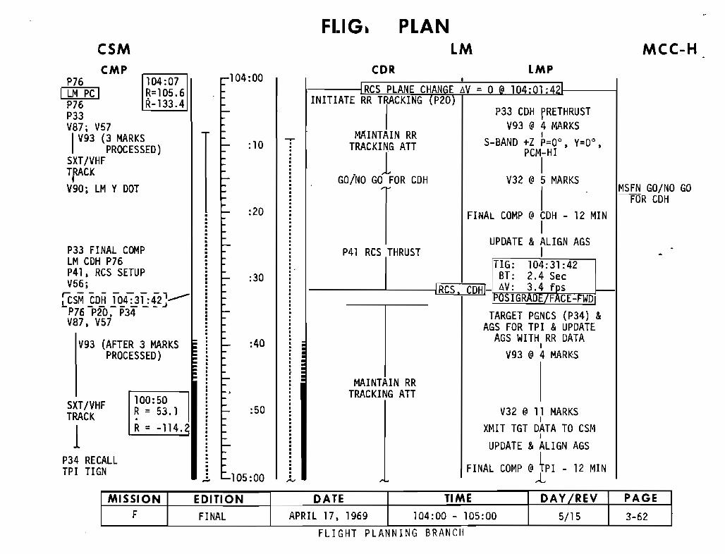
MCC-H
MSFN GO/NO GO-rDR CDH
LMP
PLANLM
CDR
V32 @ 11 MARKSI
XMIT TGT DATA TO CSMI
UPDATE &ALIGN AGSI
FINAL COMP @~PI - 12 MIN
,RCS PLANE CHANGE t>V = 0 • 104:01:
MAINTAIN RRTRACKING ATT
INITIATE RR TRAj
CKING (P20) P33 COH fRETHRUST
V93 @4 MARKSMAINTAIN RR I
TRACKIN.G ATT S-BANO ;~M~~r, Y=oo,
. J- IGO/NO GO FOR COH V32 @ 5 MARKS
IFINAL COMP @CDH - 12 MIN
IUPDATE &ALIGN AGS
P41 RCS THRUST I
ITIG: 104:31:42
-----L---IRCS, CDH,-Jtl"':~;m~~~:~EEEQj'-~ FE-FWD
TARGET PGNCS (P34) &AGS FOR TPI &UPDATE
AGS WITH RR DATAI
V93 @ 4 MARKS
:50
:40
:30
:20
:10
105:00
104:00
•··•·..;.
104:07R=105.6R-133.4
RKSCESSED)
DOT
COMP
ETUP
4:31:42'''''''--___ J
34
ER 3 MARKSCESSED)
100:50R = 53.1.R = -114.
SXT/VHFTRACK
1P34 RECALLTPI TIGN
P33 FINALLM CDH P76P41, RCS SV56;
~SM EDB .fIl.P76 P20. PV87, V57
V93 (AFTPRO
CSMCMP
P76I LM PC I
P76P33V87: V57
IV93 (3 MAPRO
SXT/VHFTfACKV90: LM Y
MISSION EDITION DATE TIME DAY fREY PAGE
F FINAL APRIL 17, 1969 104:00 - 105:00 5/15 3-62FLIGHT PLANNING BRANCH
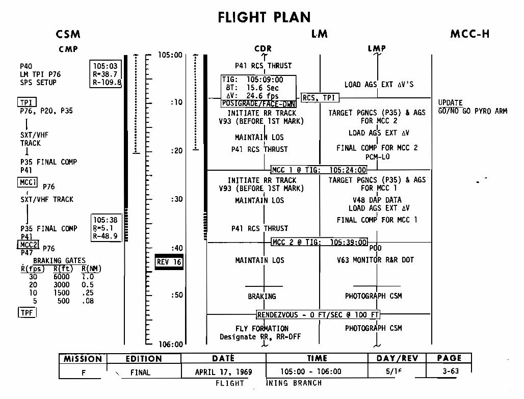
MCC-H
UPDATEGO/NO GO PYRO ARM
1
LMP
TCDR
1""
FLIGHT PLANLM
P41 RCS THRUSTI
TIG: 105:09:00 LOAD AGS EXT oV'SBT: 15.6 Sec~]RCS, TPI I I
INITIATE RR TRACK TARGET PGNCS (P35) &AGSV93 (BEFORE 1ST MARK) FOR MCC 2
MAINTAI~ LOS LOAD AG1S EXT oVI I
P41 RCS rRUST FINAL COMP FOR MCC 2PC,-LO
MCC 1 @TIG: 105:24:00INITIATE RR TRACK TARGET PGNCS (P35) &AGS
V93 (BEFORE 1ST MARK) FOR MCC 1I I
MAINTAIN LOS V48 DAP DATA
ILOAD AGS EXT oV
FINAL COM~ FOR MCC 1P41 RCS THRUST
MC 2 @ TIG: 105:39:P 0
MAINTAIN LOS V63 MONITdR R&R DOT
--t- -J-BRAKING PHOTOGRAPH CSM
IRENDEZVOUS - 0 FT/SEC @100 FT
FLY FO~TION PHOTOGR!lPH CSMDesignate RR, RR-DFF
:50
:20 -
:30
:10
106:00
105:00 -:-•
:40
lREV 16j
-105:03R=38.7R-109.!
105:38~=5.1
R-48.9
~).0.52508
CSMeMP
P40LM TPI P76SPS SETUP
(ill]P76, P20, P35
ISXT/VHFTRACK1
P35 FINAL COMPP41
IMCCll P76I
SXT/VHF TRACK
jP35 FINAL COMP
...Ell~P76P47
BRAKING GATESR(fps) !illi) lli!1
30 6000 120 3000 010 15005 500
(TPF I
MISSION I EDITION DATE TIME DAY fREY PAGE
F I , FINAL APRIL 17. 1969 105:0D - 106:00 5/1- 3-63FLI GHT NING BRANCH

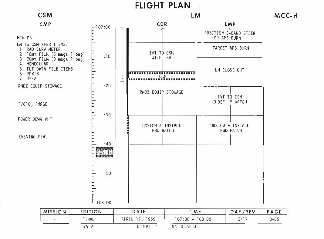
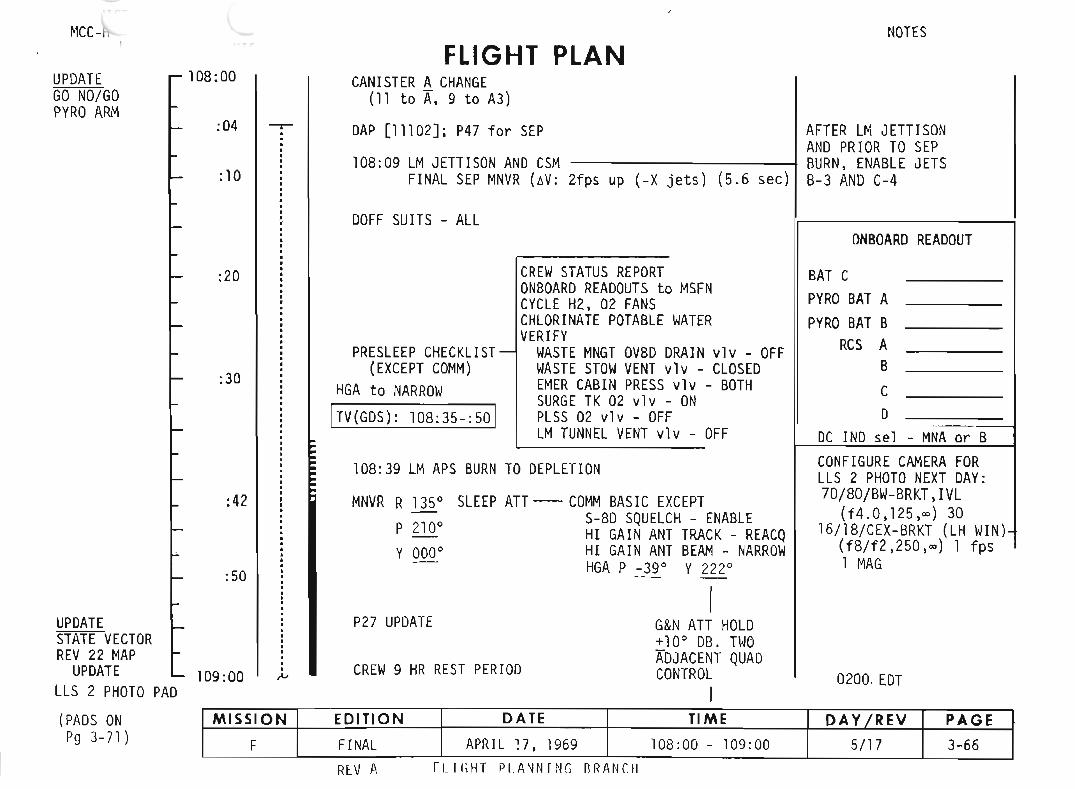
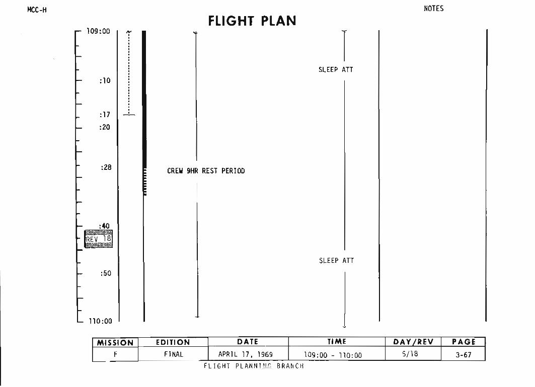

~lCC-" NOTES.
FLIGh PLAN110:00
:03
SLEEP ATT
:30
:40
111:00
:15
:27
REV 19
112:00
CREW 9HR REST PERIOO
SLEEP ATT
MISSION EDITION DATE TIME DAY/REV PAGE
F FINAL APRIL 17. 1969 110:00 - 112:00 5/19 3-68FLIGHT PLANNING BRANCH

MCC-H
FLIGHT PLANNOTES
112:00
SLEEP An
:39 •
113:00 CREW 9HR REST PERIOO
:13
:26
SLEEP An
114:00 ..,.,.
BRANCHFLI GHT PLA
MISSION EDITION DATE TIME DAY 'REV PAGE< FINAL APRIL 17 1969 112:00 - 114:00 '/20 3..69_
'--

MeL
114:00
:30
:38
115:00
:11
:24
IW
:57116:00
·:·•:··•·i••·•I
FLIGHT PLAN
CREW 9HR REST PERloo
rSLEEP An
R 1350 HGA
P 2100 P _39 0
Y 0000 Y 221 0
SLEEP An
NOTES
MISSION EDITION DATE TIME DAY fREV PAGE
F FINAL APRIL 17. 1969 114:00 - 116:00 5/21 3-70
FLIGHT PLANNING BRANCH
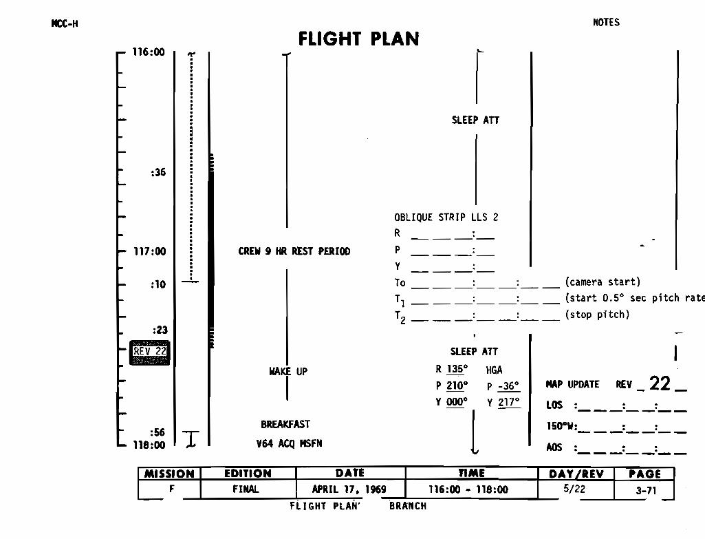
IItt-H NOTES
116:00FLIGHT PLAN
SLEEP ATT
:36
OBLIQUE STRIP LLS 2
R
P ----Y •----To :__:__ (camera start)
T1 :__:__ (start 0.50 sec pitch rate
T2 :__:__ (stop pitch)
117:00
:10
:23
11 22
'
:56118:00 T
CREW 9 HR REST PERIOO
IIAKE UP
IBREAKFAST
V64 ACQ MSFN
SLEEP ATT
R 1350 HGA-.P 2100 P _36 0
'~l ,m'
IMAP UPDATE REV _ 22_LOS : :__:__
15D"W: ::-------AOS: ::-------
BRANCHFLI GHT PLAN
MISSION EDITION DATE TIME DAY fREV PAGEF FINAl APRIL 17. 1969 116:00 - 118:00 5/22 3-71
- -,


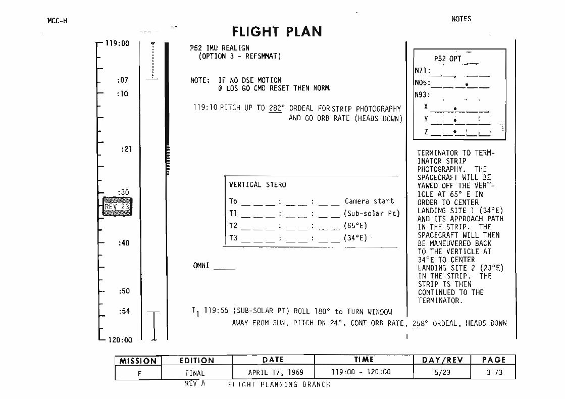
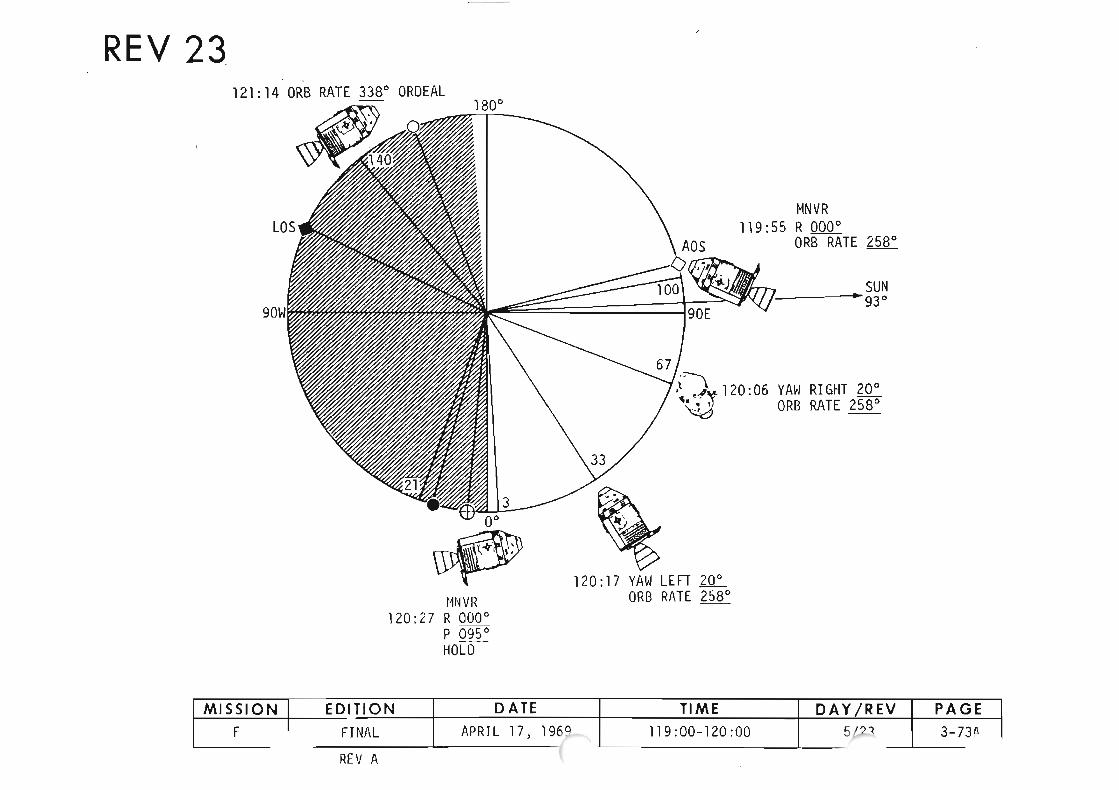
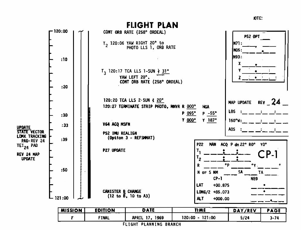
V64 ACQ MSFN
120:20 TCA LLS 2-SUN • 200
120:27 TERMINATE STRIP PHOTO. MHVR R 0000
P 0950
Y~
P52 IMU REALIGN(Option 3 - REFSMHAT)
HGAP _550
Y 1870
MAP UPDATE REV _ 24 _LOS : :__:__
ADS = :__:__
P22 MAN ACQ P dn 220 ROO YDo
o
•
CP-l
---,--------•
• •,-_.__.-
T ••l ~_.__
T ••2 __ • _,,__
R op oy.---. --- ---.Nor S NM __ SA __TA __
CP-l NB9+00.875+85.073+000.00
LAT
LONG/2ALT
P27 UPDATE
CANISTER B CHANGE(12 to 8. 10 to AJ)121 :00 ,..,
MISSION
F
EDITION
FINAL
DATE
APRI L 17. 1969
TIME
120:00 - 121 :00
PAGE
3-74FLIGHT PLANNING BRANCH
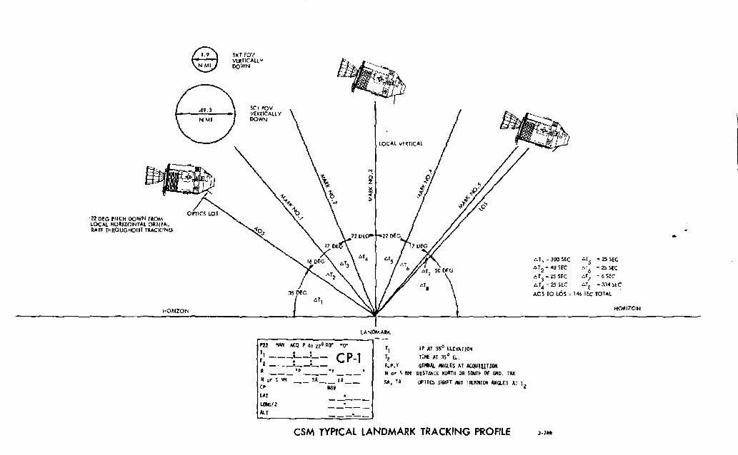
"22 DEG PITCH DOWN fROM.LOCAL HO~IZONTAL OUITALUIE THROUGIiOUT lUCKING
HO~IZON
~\ii5I
SXI rov~T1CALLY
DOWN
SCTroVVUIICALLYDOWN
'".ozl:i..:li
LOCAL VEUICAl
"T) = JOOSfC "l5 = 25 SEC
"T2 ~ ~o SEC "T6 = 25 SEC
"IJ ~ 25 SEC "17 • 6 SEC
"T~ = 25 SEC "Ta ~ 334 SEC
AOS TO lOS = T46 SEC TOTAL
HO~IZON
P22 !IAN ACQ P dn 220 ~Q' W'
T .' CPr1---~-:-- -1
2'_,,""""""-~_.__R (lip ofIy
N or S NHCP
LAT
Lc.«;/2AU
SA TAHa9
-'
LANOMA~K
I)
12R,P, Y
N o. S Nfol
SA, TA
IP AT ,50 ELUAHON
TI~ AI 3,0 u.
G'18AL ....GLES AT ACQI1lli!QIt01 STAA CE NORTH OR SOUTH OF ~O. IRK
OP TI CS SHAFT HW TRlJIOIION AllGLfS AT T2
CSM TYPICAL lANDMARK TRACKING PROFILE 3-14,\
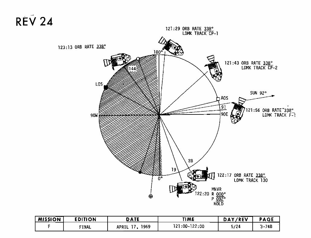
-
REV 24
90W
121:43 ORB RATE~LOMK TRACK CP-2
121:56 ORB RATE"338"LOMK TRACK F-l
28
__1_9 ~~ 122:17 ORB RATE~~ LOMK TRACK 130
~ MNVR~122:20 R 000"
P 092 0
HOLO
MISSION EDITION DATE TIME DAY fREY PAGEF FINAL APRIL 17. 1969 121 :00-122:00 5/24 3-74B
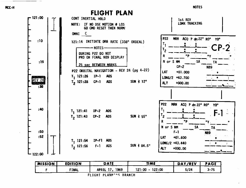
P22 ORBITAL NAVIGATION - REV 24 (pg 4-22)T1 121:26 IP-1 ADST2 121:28 CP-1 AOS SUN • 120
I
•
•
0Y 0
••---1'--t........ j ......_·~~--...
SA TA-~ -- --.
N89
I
R 0p- ----. --~ .--...--~N or S NM SA TA- -..-. ..--.~ ~~.
CP-2 N89
+01.000
+63.700
+000.\00
lATlCl4G/2AlT
NOTES
1st REVU»lK TRACKING
P22 MAN ACQ P dn 22° RO° yoo
T •• '1 --_. ._-' CP 2T •• -2 ••.-.-.. -.----~-..........~
P22 MAN ACQ P dn 220 ROO yoo
11 -_:_: =-- F 112 •• -- ~~.....--.~-.-.,-~
R op oy. 0--..-.....; _. ~ , .........~~
N or S NMF-1
LAT +01.600
LONG/2 +43.440AI.1 +000. 0.0
SUN f 55°
SUN f 84.5°IP-Fl AOSF-l AOS
IP-2 ADS
CP-2 ADS
T1 121:54T2 121:56
FLIGHT PLANCONT INERTIAL HOLDNOTE: IF NO DSE MOTION. lOS
GO CMD RESET THEN NORM!OMNI C
121:14 INITIATE ORB RATE (338° ORDEAL)
r---NOTES,----DURING P22 DO NOTPRO ON FINAL N89 DESPLAY
25 sec BETWEEN R
T1 121:41T2 121:43
......,•••·••·•·
I
:19
:40
:50:52
:10
122:00
121 :00
fREY 241:30
MCC-H
MISSION EDITION DATE TIME DAY IREV PAGE
F FINAL APRIL 17. 1969 121:00 - 122:00 5/24 3-75.FLIGHT PLAN~~~~ BRANCH

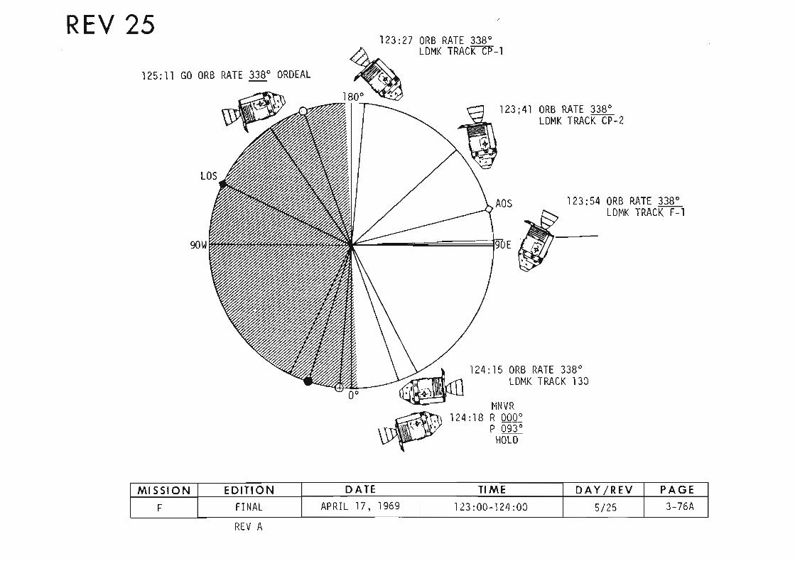
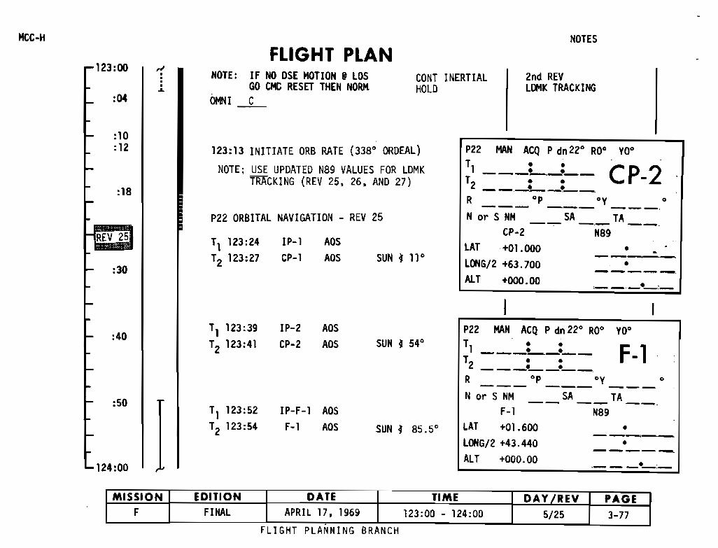
NOTESMCC-H
123:00
:04
..-•···~
FLIGHT PLANNOTE: IF NO OSE MOTION i LOS
GO CMe RESET THEN NORMOMNI C
CONT INERTIALHOLD
2nd REVLIlMK TRACKING
:10:12
:18
123:13 INITIATE ORB RATE (338' ORDEAL)
NOTE: USE UPDATED N89 VALUES FOR LDMKTRACKING (REV 25, 26, AND 27)
P22 MAN ACQ P dn 22' RD' YO'
T1 L-=__ CP-2T2 __._L_;__R op oy 0
P22 OR8ITAL NAVIGATION - REV 25
•---._-.
--- ---,
_._-,--•
,_._._e_:_
Nor S NM __SA_._ TA __CP-2 N89
LAT +01.000LOHG/2 +63.700ALT +000.00
SUN ~ II'ADSADS
IP-1CP-l
T1 123:24T2 123:27
:30
REV 25
T1 123:39 IP-2 ADS P22 MAN ACQ P dn 22' RD' YO':40 T2 123:41 CP-2 ADS SUN ~ 54' T1 • • F-l---!.....-.-._-
T2
••-_._~-'--
R 'P 'Y •--- --- ---Nor S NM SA TA:50 -- -- --T1 123:52 IP-F-1 ADS F-l N89
T2 123:54 F-l ADS SUN ~ 85.5° LAT +01.600 •---LOHGI2 +43.440 •-----ALT +000.00 .___e_:_124:00
FLIGHT PLANNING BRANCH
MISSION EDITION DATE TIME DAY IREV PAGEF FINAL APRIL 17. 1969 123:00 - 124:00 5/25 3-77.

P22 MAN ACQ P dn 22' RO' YO'
MCC-H
124:00FLIGHT PLAN
EVENING MEAL
CONT ORB RATE {33a' ORDEAL}r
NOTES
2nd REV LOMK TRACKING1700 EDT
AOS ' '__:__
150'W: :__,__
LOS : :__:__
MAP UPDATE REV _ 26 _
,
,
-_.-
•
•
130
-----•-----_: e_:_
_._---•---.--.
SA TA-- -,- --Na9
SA TA-- -.- --Na9
N or S NM130
+01.266
+11.839
-DOL 73
T ••1 t......_.__
T2 ---_:__:_-R op oy--- --- ---
LAT
LONG{2
ALT
--- --- ---
r
N or S NMCP-l
LAT +00.875
LONG/2 +85.073
ALT +000.00
P22 MAN ACQ P dn 22' RO' YO'
T1 L_=-_ CP-1T2 --_:__:_-R op oy
SUN ~ 22'
IP-130 ADS
Ll»lK 130 AOS (LLS-2)
R 000' HGA
P 093' P -70'Y 000' Y 191'
V64 ACQ MSFN
P52 IMU REALIGN(Option 3 - REFSMMAT)
T1 124:13
T2 124:15
124:1B MNVR
P27 UPDATE
:50
:40
:10
:20
:30
125:00
UPDATESTATE VECTORTEI
26PAD
Ll»lK TRACKINGPAD· REV 26
REV 26 MAPUPDATE
DEBRIEF Ll»lKTRACKING
MISSION EDITION DATE TIME DAY fREV PAGE
F FINAL APRIL 17, 1969 124:00 - 125:00 5/25 3-78
FLIGHT PLAN.' , BRANCH
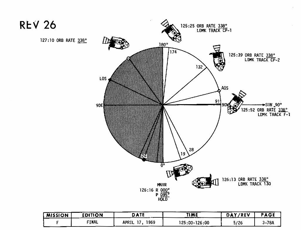
Rl::v 26127:10 ORB RATE 3380- ~
.. 125:25 ORB RATE 3380
lDMK TRACK CP-1
..1800
125:39 ORB RATE 3380
lDMK TRACK CP-2
90E • SUN ...900
125:52 ORB RATE ~lDMK TRACK F-l
0'~~ 126:13 ORB RATE 33B'
fJfiVR ~ lDMK TRACK 130126:16 R 000 0
P 095 0
HOlD
MISSION EDITION DATE TIME DAY IREV PAGE
F FINAL APRIL 17, 1969 125:00-126:00 5/26 3-78A
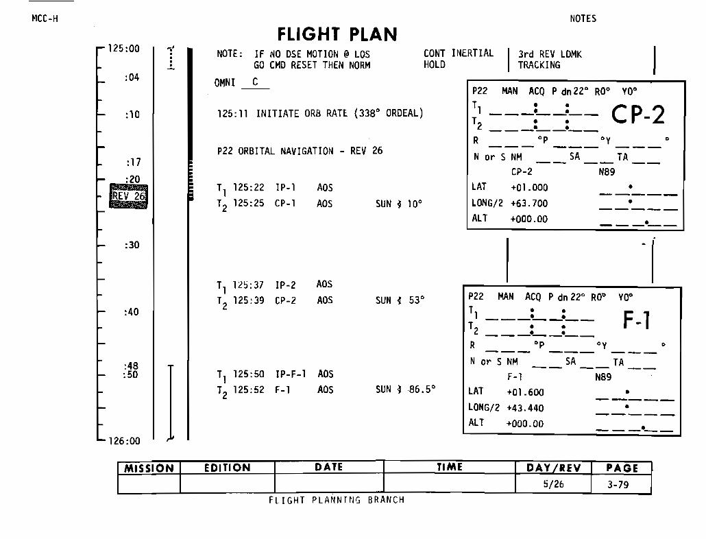
NOTES
--- --- ---
P22 MAN ACQ P dn 22" RO" YO"
T1 ---=--=-- CP-2
T2 --_:__:_-R 0p oy
125:11 INITIATE ORB RATE (338" ORDEAL)
0_-
o
o-----
3rd REV LOMKTRACKING
N or S NM SA TA-- -- --CP-2 N89+01.000+63.700+000.00
LATLONG/2ALT
CONT INERTIALHOLD
SUN lID"ADSADS
FLIGHT PLAN
P22 ORBITAL NAVIGATION - REV 26
T1 125:22 IP-lT2 125:25 CP-l
NOTE: IF NO OSE MOTION @ LOSGO CMO RESET THEN NORM
OMNI C
~.·••·-
:10
:04
:17
:20aZz,
125:00
fICC-H
:30
:40
T1 12,:37T2 125:39
IP-2CP-2
ADSADS SUN l 53" MAN ACQ P dn 22" RO"
o 0o 0-------o 0___0__0_-
0p oy
YO"
F-l--- --- ---
SA TA-- -- --N89
LATLONG/2ALT
:48:50
126:00
T1 125:50T2 125:52
IP-F-lF-l
ADSADS SUN l86.5"
N or S NMF-l+01.600+43.440+000.00
o-----o-----
0_-
MISSION EDITION DATE TIME DAY /REV PAGE,/26 3-79
FLIGHT PLANNinG BRANCH
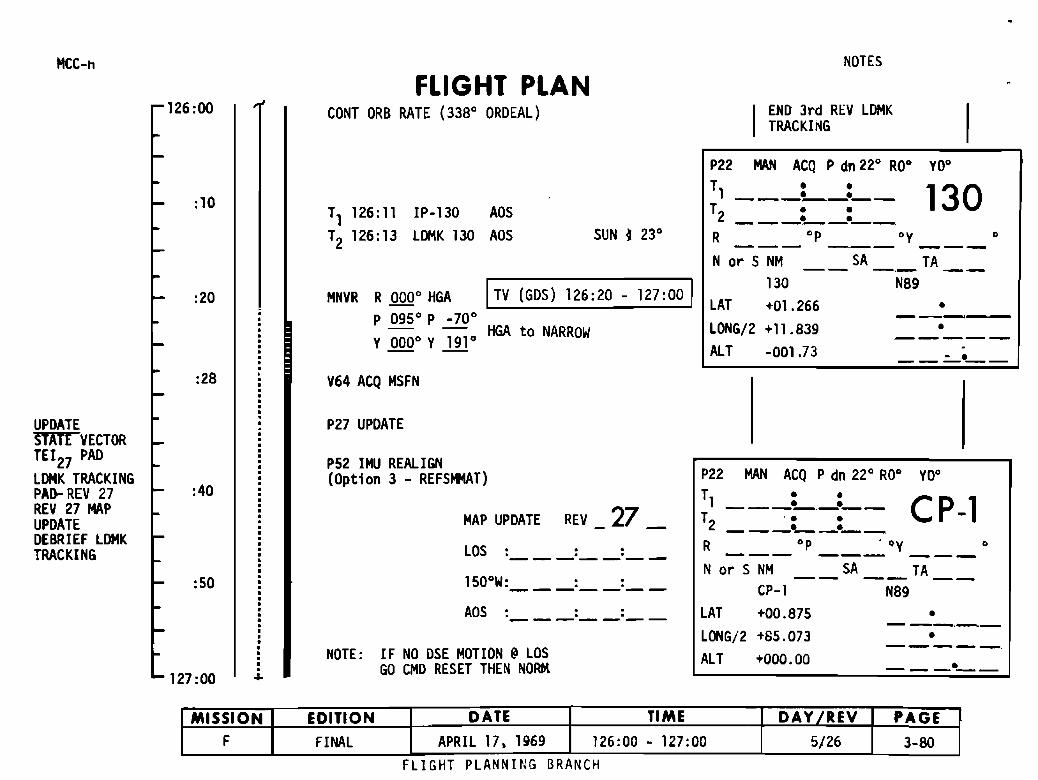
MCC-h
126:00FLIGHT PLAN
CONT ORB RATE (338" ORDEAL)
NOTES
END 3rd REV LDMKTRACKING
:10T1 126:11 IP-130 AOS
T2 126:13 LDMK 130 AOS SUN ~ 23"
P22 MAN ACQ P dn 22" RO" YO"
~~ ==; ;=130R op oy 0--- --- ---
SA TA-- -,- --NB9
:20 MNVR R 000" HGA ITV (GDS) 126:20 - 127:00 IP 095" P _70"
- - HGA to NARROWY 000" Y 191"
N or S NM
130
LAT +01.266
LONG/2 +11.839
ALT -001.73
•-----•
.-:28 V64 ACQ MSFN
--_._-----_.
___ op __--:. ~V "
._-••
CP-1MAN ACQ P dn 22" RO" YO"P22
T1 L._:__T2 --_:__:_
RNor S NM __ SA __ TA __
CP-l N89
LAT +00.87S
LONG/2 +8S. 073
ALT +000.00
MAP UPDATE REV 27LOS: ::-------150"W: :__:__
AOS : :__:__
P27 UPOATE
P52 IMU REALIGN(Option 3 - REFSMMAT)
NOTE: IF NO DSE MOTION @LOSGO CMD RESET THEN NORK
•••·•·...
:50
:40
127:00
UPDATESIDE VECTORTEI27 PAD
LDMK TRACKINGPAo- REV 27REV 27 MAPUPOATEDEBRIEF LDMKTRACKING
MISSION EDITION DATE TIME DAY fREY PAGE
F FINAL APRIL 17. 1969 126:00 - 127:00 5/26 3-80FLIGHT PLANNING BRANCH
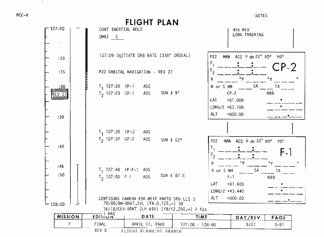
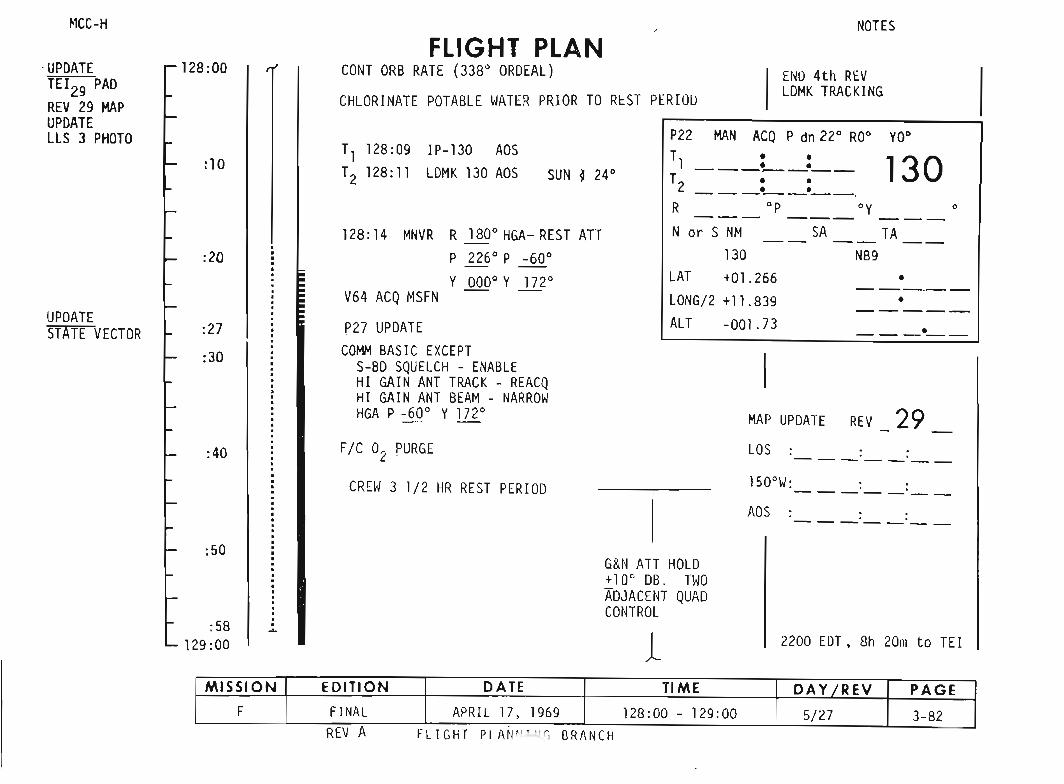
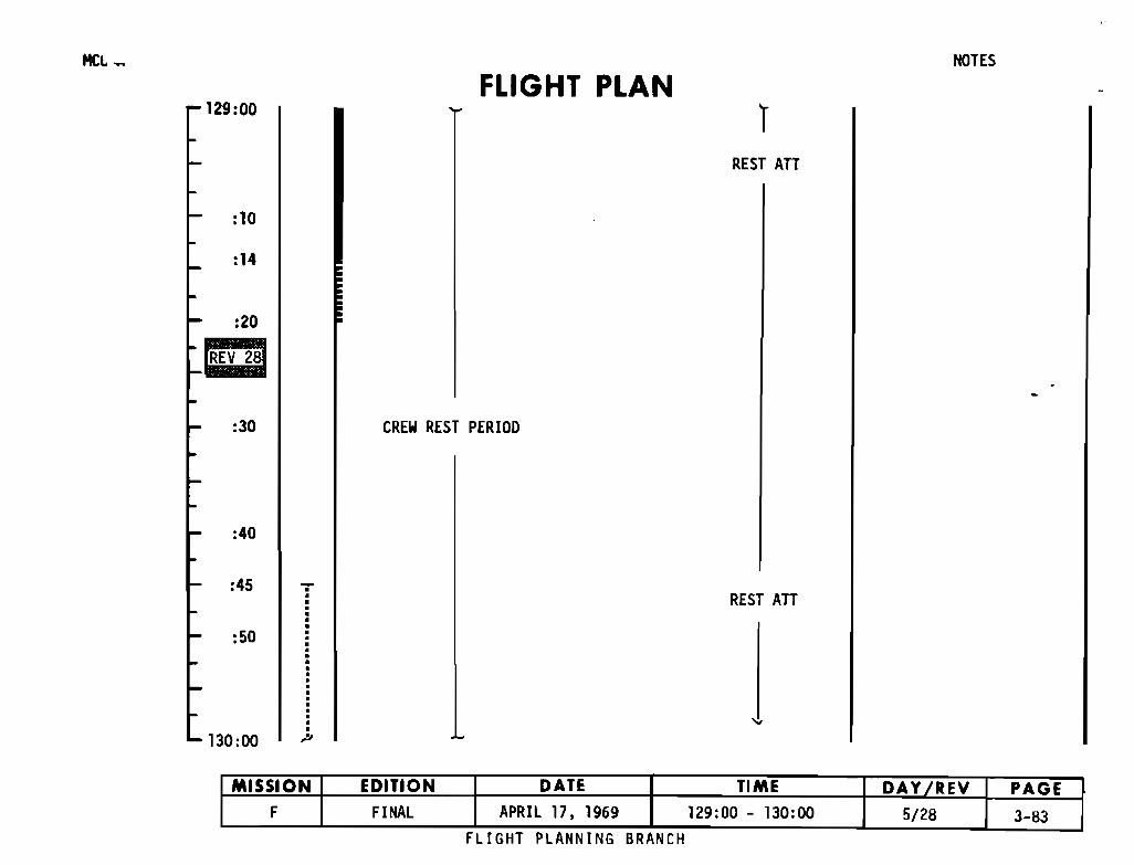
129:00
:10
:14
:20
Em:30
:40
:45
:50
130:00 '"
FLIGHT PLAN
CREW REST PERIOO
IREST An
REST An
NOTES
MISSION EDITION DATE TIME DAY fREV PAGEF FINAL APRIL 17. 1969 129:00 - 130:00 5/28 3-83
FLIGHT PLANNING BRANCH
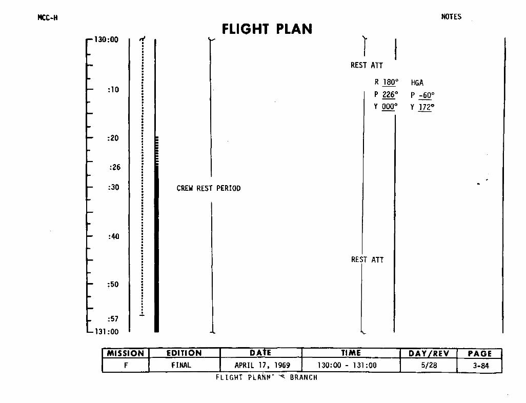
MCC-H
130:00
: 10
:20
:26
:30
:40
:50
:57131:00
•
•
-
FLIGHT PLAN
CREW REST PERIOO
REST ATT
R 1800
P 2260
Y0000
REST ATT
HGA
P -600
Y 172°
NOTES
MISSION EDITION DAtE TIME DAY IREV PAGEF FINAL APRIL 17. 1969 130:00 - 131 :00 5/28 3-84
FLIGHT PLAN~~ ~ BRANCH
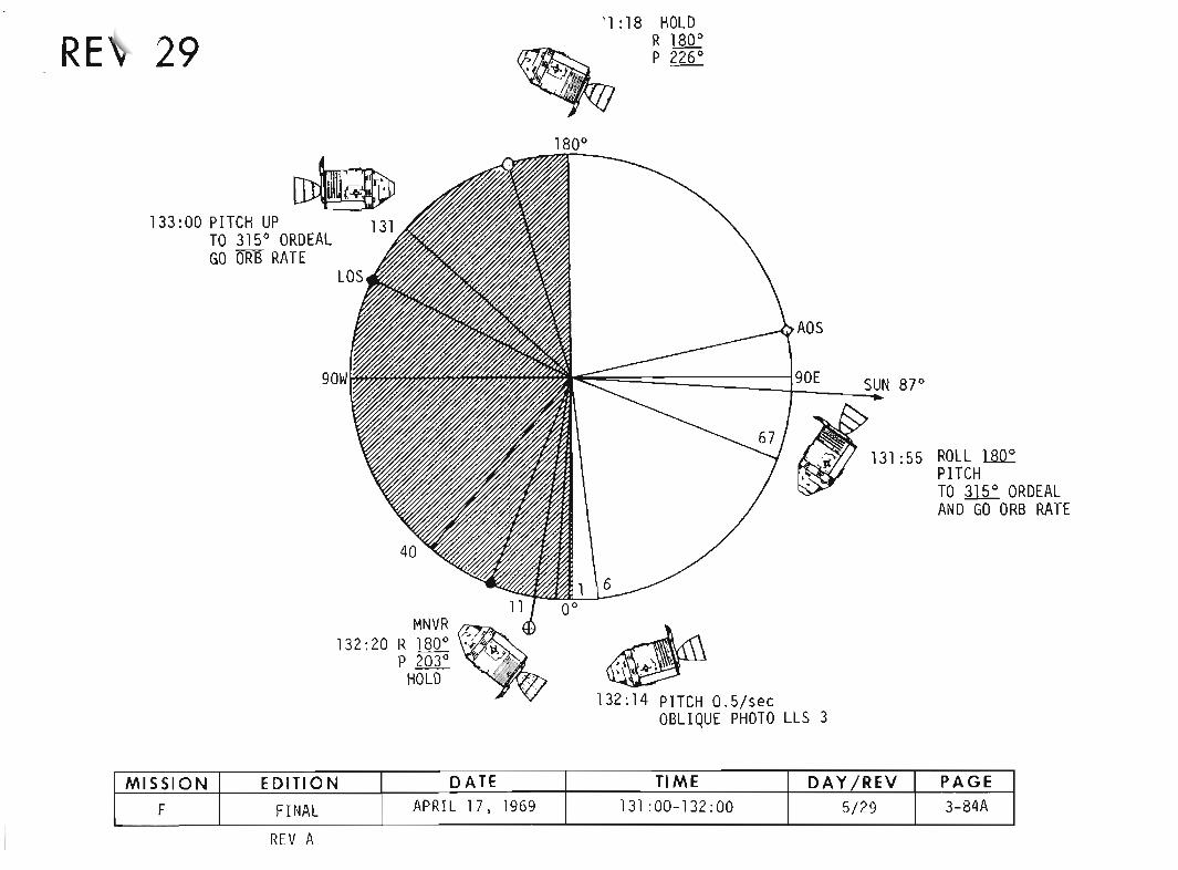


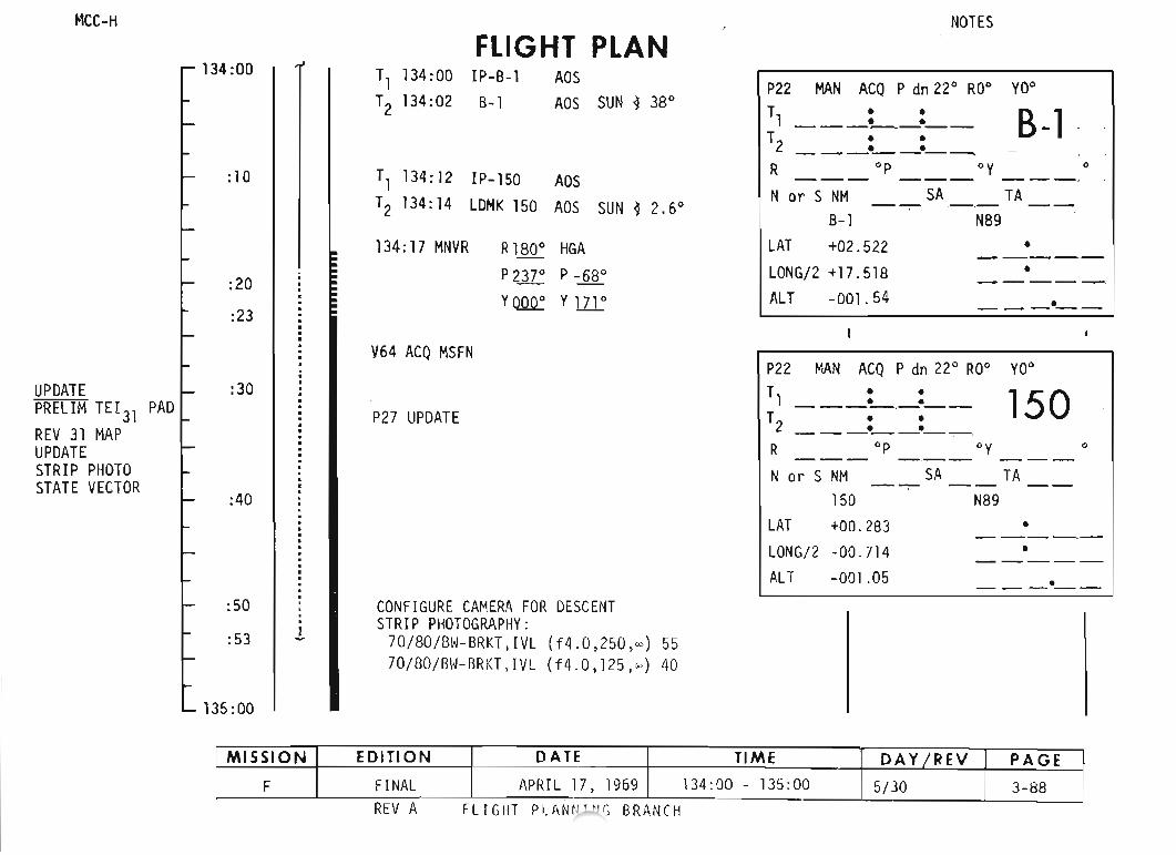
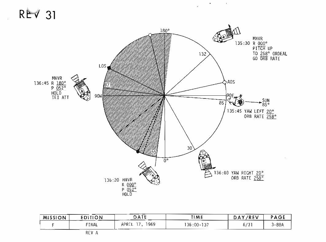
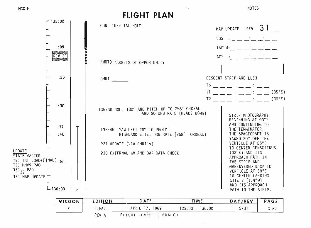
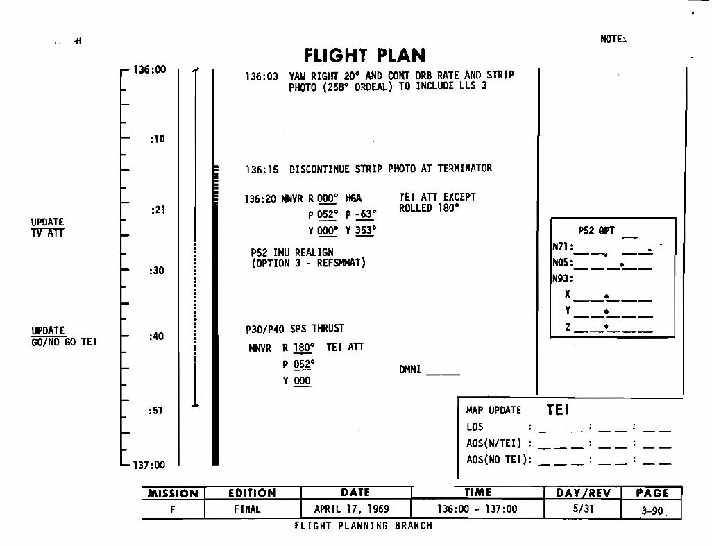
.. ·tt
136:00
NOTE>.
FLIGHT PLAN136:03 YAW RIGHT 200 AND CONT ORB RATE. AND STRIP
PHOTO (25BO ORDEAl) TO INCLUDE LLS 3
:10
136:15 DISCONTINUE STRIP PHOTO AT TERMINATOR
MAP UPDATE TE ILOS : __ : __AOS(W/TEI) : : __ : __AOS(NO TEl): : _._: __
UPDATETVATT
UPDATEGO/NO GO TEl
:21
:30
:40
:51
137:00
1
136:20 MNVR R0000 HGAP 0520 P _63 0
Y0000 Y3530
P52 IMU REALIGN(OPTION 3 - REFSMMAT)
P30/P40 SPS THRUST
MNVR R!§Q.° TEl ATTP 0520
Y 000
TEl ATT EXCEPTROLLED 1800
OMNI __
P52 OPT .-N71: _--, --
NOS:___L._
N93:X__
L__
Y •-----Z •-----
FLIGHT PLANNING BRANCH
MISSION EDITION DATE TIME DAy7REV PAGEF FINAL APRIL 17. 1969 136:00 - 137:00 5/31 3-90
.

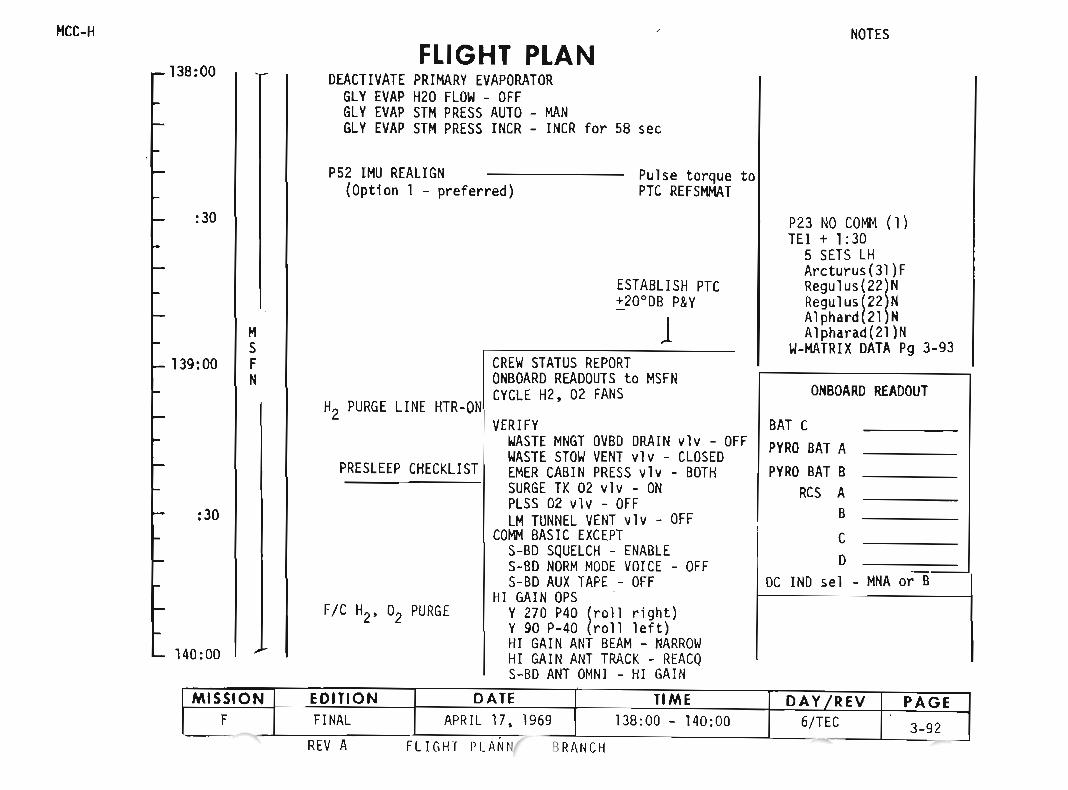

MeL-..
UPDATESTATE VECTOR
140:00FLIGHT PLAN
ECS REDUNDANT COMPONENT CHECKP27 UPDATE
PTC +20·ply
NOTES
203,000 NM from EARTH12h 2Qn to MeC526h sCm to MeC6
:30 CREW 5 1/2 HR REST PERIOD 0930 EDT
1llh 5Qn to MeC5
M W-MATRIXS
141 :00 F In the event of a loss of COHM the W-MATRIX willN be initialized to the values listed before BATCH VALUES TO Be
the next scheduled batch of si9htin9s. NR LOADED VIA V67NOTE INTO THE DSKY
The W-MATRIX is initialized only once on the Rl R2Transearth leg. 1 +00094 +00057
Batch 2 has two sets of values listed; if the 2 +02928 +00039MSFN State Vector update at GET 147:00 has not +00998 +00008
:30 been received. the first set should be used; if3received before loss of COHM occurr. the second +00998 +00008
set should be US~d. If loss of COHM occurs4after EI-30 hrs GET 161:50). and provlded"tne +00998 +00008
t!~jU hrs entry pad update has been recieved, thecurrent CMC state vector will provide reentry 5 +00998 +00008
142:00 capability, and no navigation marks will be made.6 +00998 +00008
FLIGHT PLANNINu BRANCH
MISSION EDITION DATE TIME DAY IREV PAGEF FINAL APRIL 17. 1969 140:00 - 142:00 6/TEC 3-93
"


148:00
:30
M149:00 S
FN
:30
150:00
FLIGHT PLAN
NOTEINITIAlIZE THE W-MATRIXPRIOR TO THE FIRST STAR/LUNARLDMK SIGHTING TO R1 00094
Rz 00057
THE W~MATRIX WILL NOT BERE~INITIALIZED PRIOR TO THEREMAINING P23 SIGHTINGS SCHEDULED
TPTe +30° DBPlY -
PTC
NOTES
P23 NO COIt4 (2)TEI + 12:30
5 SETS LHRegulus(22)NRegulus(22)NGienah(24)FSpica(26)FSpica(26)F
W-MATRIX DATA Pg 3-93
FLIGHT PLANNING BRANCH
MISSION EDITION DATE TIME DAY IREY PAGEF FINAl APRIL 17. 1969 148:00 - 150:00 7/TEC 3-97
- .
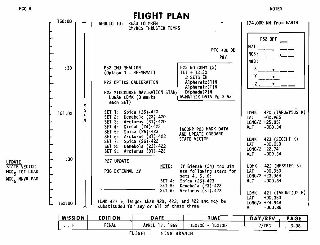
~lCC-H
FLIGHT PLAN150:00 APOLLO 10: REAO TO MSFN
rCM/RCS THRUSTER TEMPS
PTC :t.30 DBP&Y
:30 P52 IMU REALIGN P23 NO COMM (3)(Option 3 - REFSMMAT) TEl + 13:30
3 SETS EHP23 OPTICS CALIBRATION A1Pheratz~l)N
Alpheratz l)NP23 MIDCOURSE NAVIGATION STAR/ Diphada(2)N
LUNAR LDMK (3 marks I W-MATRIX DATA P9 3-93
Meach SET)
151 :00 S SET 1: Spica (26)-420F SET 2: Denebola ~23l'420N SET 3: Arcturus 31 -420
SET 4: Gienah (24)-423 INCORP P23 MARK DATASET 5: Spica (26)·423SET 6: Arcturus (31)'423 AND UPDATE ONBOARDSET 7: Spica (26)-422 STATE VECTORSET 8: Denebola (23),422SET 9: Arcturus (31)-422
UPDATE :30 P27 UPDATEsTATE VECTOR NOTE: If Gienah (24) too dimMCC5 TGT LOAO P30 EXTERNAL AV use following stars for
MCC 5 MNVR PAD sets 4, 5, 6:SET 4: Spica (26)-423SET 5: Denebola (23)-423SET 6: Arcturus (31).423
152:00 LDMK 421 is 1arger than 420, 423, and 422 and may besubstituded for any or all of these three
NOTES
174,000 NM from EARTH
P52 OPTN71 :--, --NOS: °-----N93:
X__o _
Y 0-----z 0-----
-LDMK 420 (TARUNT1US p)LAT +00.866LONG/2 +25.851ALT -000.34
lDMK 423 (SECCHI K)LAT -00.050LONG/2 +22.741All -000.34
LDMK 422 (MESSIER B)LAT -00.950LONG/2 +23.968ALT -000.34
LDMK 421 (TARUNTIUS H)LAT +00.350LONG/2 +24.949ALT -000.86
NING BRANCHFLI GHT ,
MISSION EDITION DATE TIME I DAY/REV PAGE. • F FINAL APRIL 17, 1969 150:00 - 152:00 l 7/TEC . 3-98
~

NOTES
R--PYVgx•
• Vgy, V
gzi'·1 AVe
I i FUELL lOX
: I UNBAL
ONBDARD READDUT
BAT CPYRO BAT APYRD BAT B
RCS AB
CD
DC IND sel - MNA or 8
ESTABLISH PTC
1CREW STATUS REPORTONBOARO READOUTS to MSFNCYCLE H2 02 FANSCHLORINATE POTABLE WATERVERIFY
WASTE MNGT OVBO DRAIN v1v - DFFWASTE STDW VENT vlv - CLOSEOEMER CABIN PRESS vlv - BOTHSURGE TK 02 v1v - DN
.PLSS 02 v1v - OFFLM TUNNEL VENT vlv - OFF
COMM BASIC EXCEPTS-BD SQUELCH - ENABLES-BD NORM MODE VOICE - OFFS-BD AUX TAPE - OFF
HI GAIN OPS (or OMNI DPS per MSFN)Y270 P40 (roll ri9ht)Y 90 P-40 (roll left)HI GAIN ANT BEAM - NARROWHI GAIN ANT TRACK - REACQS-BD ANT OMNI - HI GAIN
FLIGHT PLAN I BURN STATUS REPORT,--------..,1 X' X :' >" HIG
P23 NO coltot (4) - •TEl + 16:00 X x. : , BT
5 SETS EH • VA1tair(40)F ... gxOiphda(2)N -- TRIMOiphda(2)NA1pheratz{l)N X X XA1pheratz{l)N X X X
W-MATRIX OATA P9 3-93 X X X.-:-:f- .f- .
f-L-X'X X
, XI X £I! --, -1 ~-
. X! X XIREMARKS:
EMS CHECK
SXT/STAR CHECK
PRESLEEP CHECKLIST
P40/P41 SPS/RCS THRUST
F/C O2 PURGE
CANISTER A CHANGE(15 to A,'3 to A4)
TRIM To 0.2 fps1152:20 MCC5J all axes
V66 TRANSFER CSM SV TO LM SLOTAPOLLO 10: POST BURN REPORT
TV(GOS) :152: 35 - HGA to NARROW152:45
MSFN
154:00
:30
153:00
TEl+15h
:30
152:00
MCC-"h-
MISSION EDITION DATE TIME DAY IREV PAGEF FINAL APRIL 17, 1969 152:00 - 154:00 7/TEC 3-99
FLIGHT PLANNING BRANCH

MCC-HFLIGHT PLAN
NOTES
154:00
CREW 9 HR REST PERIOD163,000 NM from EARTH
SATURDAY, MAY 242300 EDT22h 5Dm to MCC6
:30PTC
MS
155:00 FN
:~ ~C
-156:00
FLIGHT PL~'NG BRANCH
MISSION EDITION DATE TIME DAY IREV PAGEF FINAL APRIL 17. 1969 154:00 - 156:00 7/TEC 3-100
.

MCC-H NOTES
FLIGHT PLAN156:00
rPTC
157:00
P23 NO COMM (5)TEl + 20:00
3 SETS LHRe9u1us (22)N
158:00 Spica(26)FSpica(26)F
W-HATRIX OATA P9 3-93
MS
159:00 F CREW 9 HR REST PERIODN
160:00PTC
161 :00
162:00
P23 NO COMM (6)TEl + 23:00
3 SETS EHAIPheratZ/I)NAlpheratz I)NAltair{40lF
W-MATRIX OATA P9 3-93
MISSION EDITION DATE TIME DAY IREV PAGEF FINAL APRIL 17. 1969 156:00 - 162:00 l/TEC 3-101
FLIGHT PLANNING BRANCH
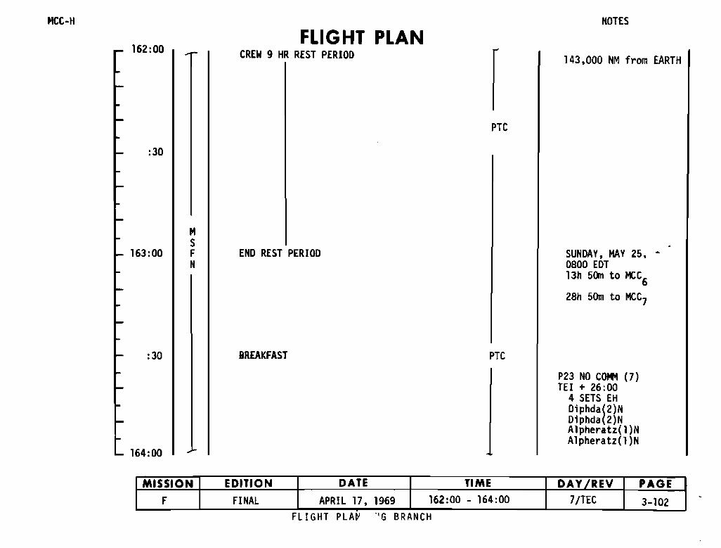
MCC-H
162:00FLIGHT PLAN
CREW 9 HR REST PERIOO
NOTES
143,000 NM from EARTH
PTC
:30
163:00
MSFN
ENO REST PERIOO SUNDAY, MAY 25. 0800 EOT13h 50m to MCC
628h 50m to MeC7
:30 BREAKFAST PTC
164:00
P23 NO COlt! (7)TEl + 26:00
4 SETS EHOiphda(2)NOiphda(2)NAlpheratz(l)NA1pheratz(l )N
FLIGHT PLA~ G BRANCH
MISSION EDITION DATE TIME DAY fREV PAGEF FINAL APRIL 17, 1969 162:00 - 164:00 7/TEC 3-102
- ,

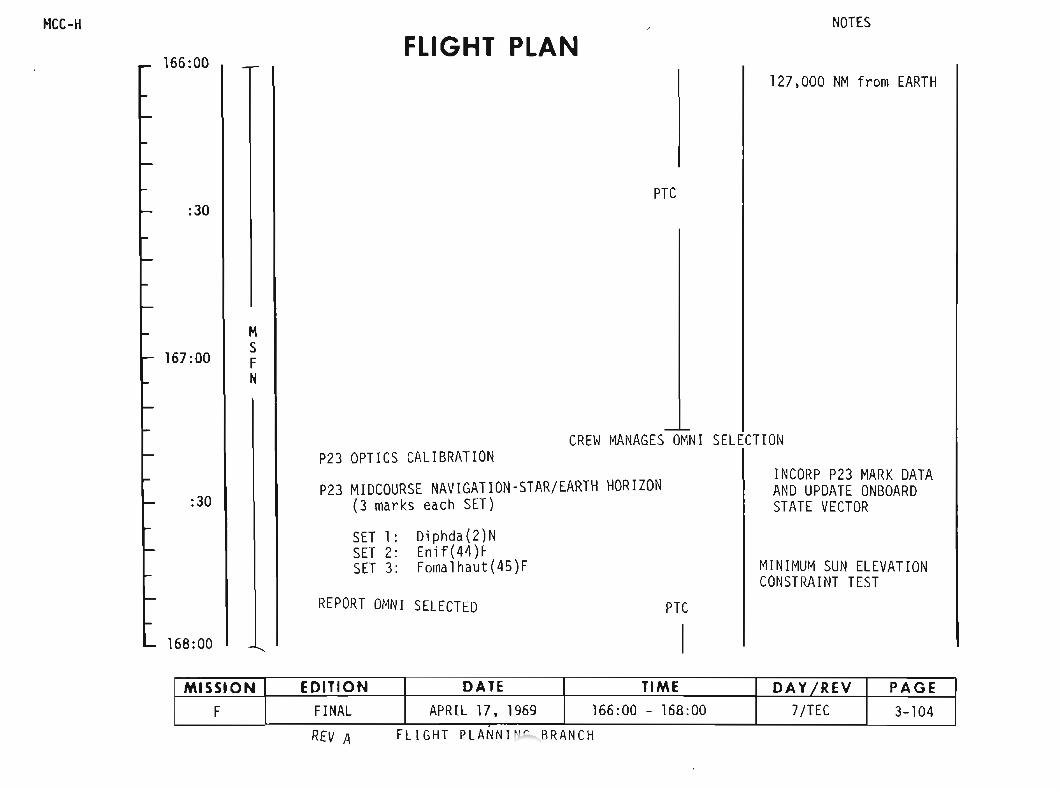
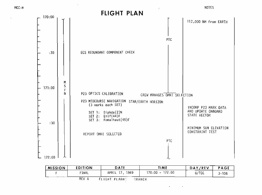

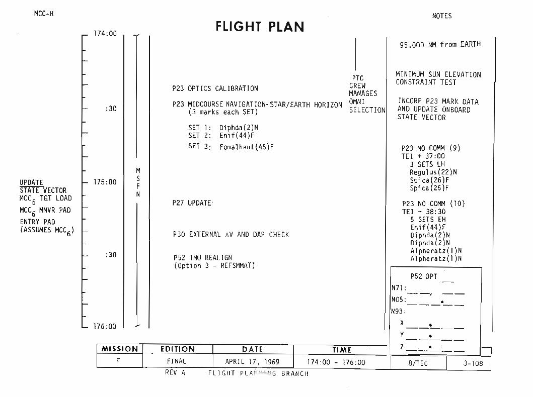

~lCC-H
176:00FLIGHT AN
~OTES
:30 P40/P41 SPS/RCS THRUST
PTe
EI-15
177 :00MSFN
1176:50 MCC6] TRIM to 0.2 fps all axes
V66 TRANSFER CSM SV TO LM SLOT
APOLLO 10: POST BURN REPORT
MNVR R__
P 090 0
y 0000
:30
REPORT OMNI SELECTED
PRESLEEP CHECKLIST (NEXT PAGE)
CANISTER A CHANGE(17 to A. 15 to A4)
178:00
F/C 02 PURGE
READ TO MSFN CM/RCS THRUSTER TEMPS SC506A6B6C60
REV A FLIGHT PLANNING BRANCH
MISSION EDITION DATE TIME DAY IREV PAGEF FINAL APRIL 17,1969 176:00 - 178:00 B/TEe 3-109

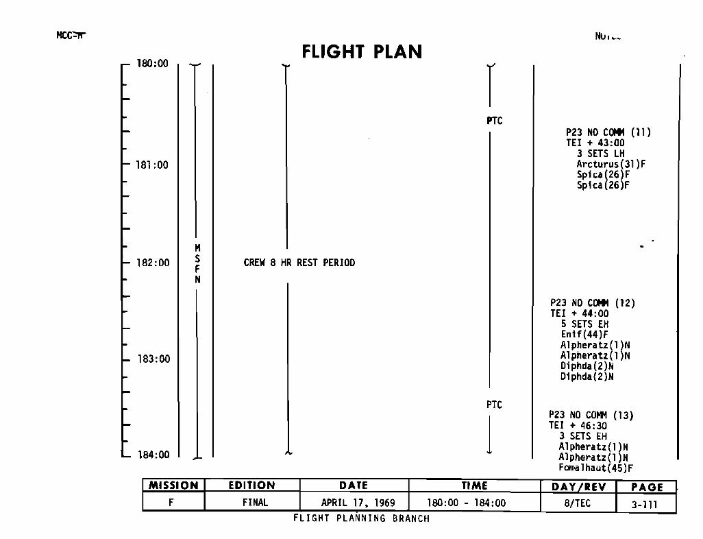
HCC":1'r
180:00FLIGHT PLAN
rNl.tl"'~
181 :00
PTCP23 NO COItl (11)TEl + 43:00
3 SETS LHArcturus(31)FSpica(26)FSplca(26)F
182:00MSFN
CREW 8 HR REST PERIOD
183:00
P23 NO COItl (12)TEl + 44:00
5 SETS EHEnlf(44)FAlpheratz (1 )NA1pheratz(1 )NDiphda(2)NDiphda(2)N
184:00
PTC
1P23 NO COI'M (13)TEl + 46:30
3 SETS EHA1pheratz(1 )NAl pheratz (1 )NFamaIhaut(45)F
FLIGHT PLANNING BRANCH
MISSION EDITION DATE TIME DAY IREV PAGEF FINAL APRIL 17. 1969 180:00 - 184:00 8/TEC 3-111.

MCC-H
184:00FLIGHT PLAN
1NOTES
PTC
:30CREW 8 HR REST PERIOO
185:00
MSFN
PTC
:30
186:00 ENO REST PERIOO
FLIGHT PLN-.NG BRANCH
MISSION EDITION DATE TIME DAY/REV PAGEF FINAL APRIL 17, 1969 184:00 - 186:00 8/TEC 3-112
- •
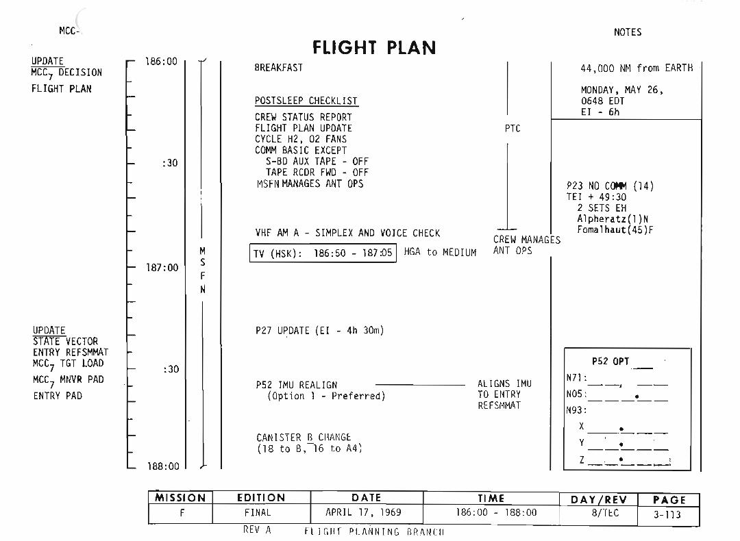

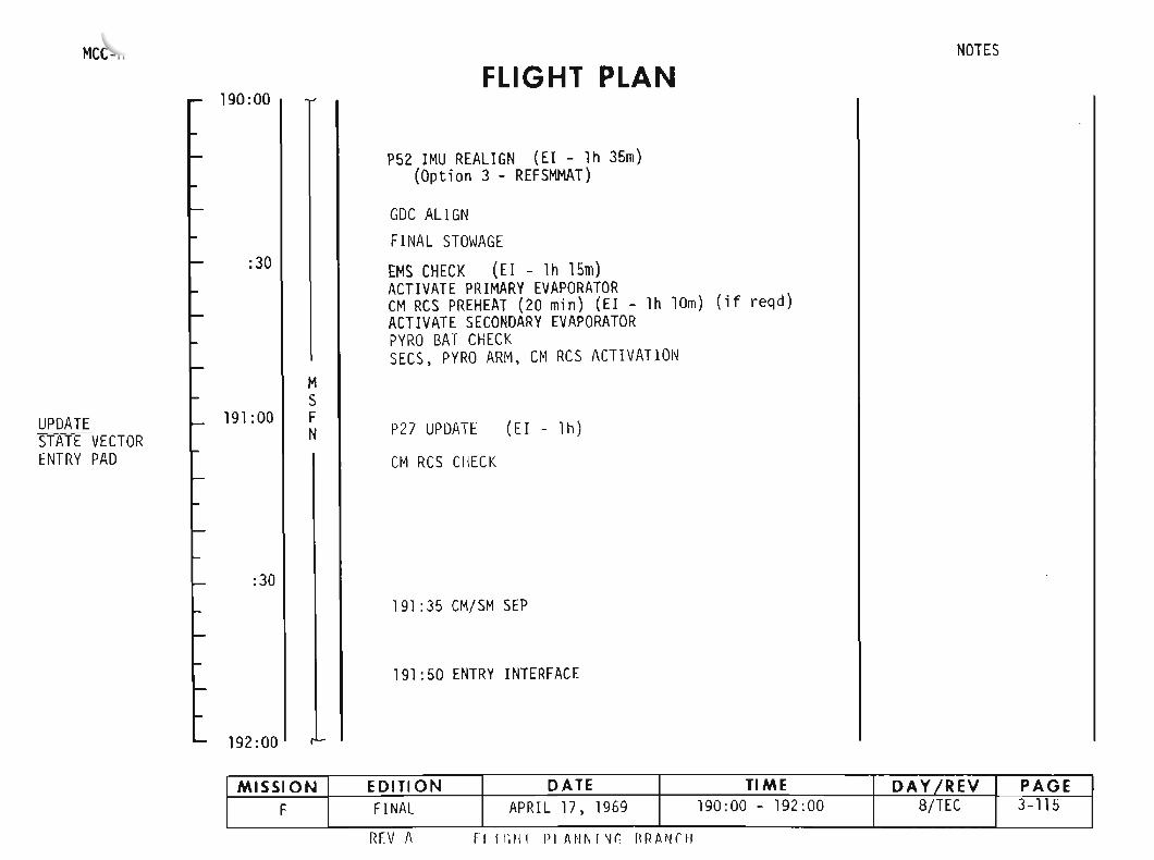
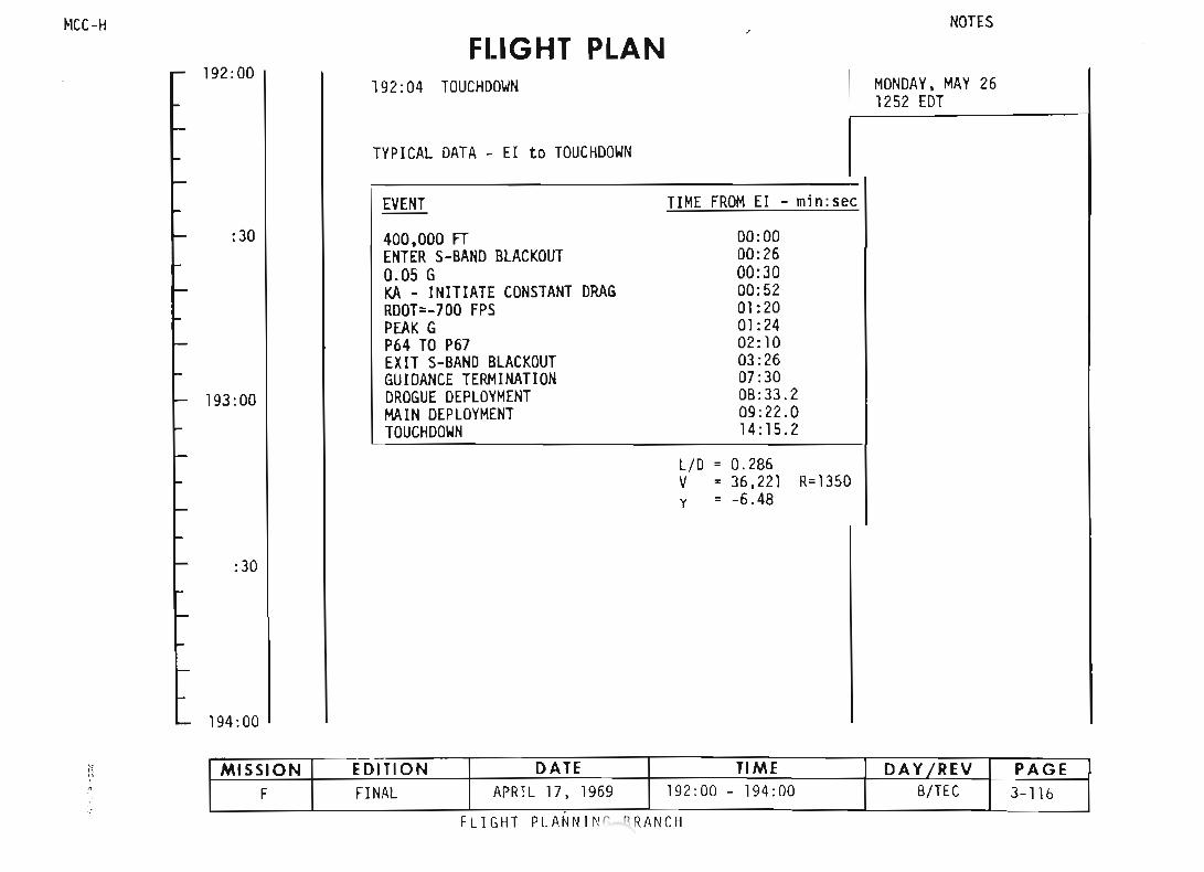

SECTION 4 - DETAILED TEST OBJECTIVES

SECTION 4
OETAILED TEST OBJECTIVE ACTIVITIES
This section contains the activity sunmaries which reflect the testobjectives for Mission F as described in uMission Requirements F Type Mission",SPD9-R-037, dated February 11,1969. These activity·summaries are presented inthe approximate sequence in which they are planned to occur during- the mission.In the case of activities which are repeated in the mission plan. they aredescribed only once in this summary. Those test objectives which do not relateto specific mission activities and require minimal support for accofl1tJ1ishment aregrouped at the end of this section as "Passive Tests." Test objective requirements which are not scheduled in this flight plan are identified as being notimplemented. "N. I."
Each activity summary provides the following information:
A. TEST OBJECTIVES. This is the listing of the Functional TestObjectives (conJ;>lete or partial) which relate to theparti cul ar acti vi ty;
B. TEST REQUIREMENTS. Here the special test prerequisites (andmission phase if necessary) are presented in addition to briefs taterrents of the requi rements for perfonning the acti vity;
C. TEST PROCEDURES/CHECKLISTS. These are the proceduralreferences for the performance of the activi ty as far asthe test objectives are concerned; and
D. DATA REQUIREMENTS. This part of the summary identifies thegross data which are needed for evaluation of test resultsin terms of flight crew and ground support requirements.
Cross references for relating Detailed and Functional Test Objectives withthe acti vity summari es and re 1ati ng acti viti es to Functi ana1 Tes t Objecti ves, areprovided as the initial part of this section.
The following ground rules are to be used in implementing data requirerents:
A. The collection of highly desirable (HD) data should not constrainthe ti me 1i ne of the crew procedures.
B. CSM data storage equipment (DSE) HBR recording is needed only whenMSFN coverage is not available and when mandatory data are required.
C. Post-flight debriefing requirements which are fulfilled by real timetransmission of data per the DATA REQUIREMENTS sections may be deletedfrom the post-flight debriefing.
4-1

ACTIVITY
TABLE 4-1 MISSION ACTIVITY/TEST OBJECTIVE
CROSS REFERENCE
FTO
Trans/Docking/Ejection
PTC
.Mi dcourse Nav; gati on
MCC
LOI
lM Sensor Biases
LM IMU Alignment
lunar landmark Tracking
LM Inspection by CSM
001
Near Lunar Surface Act; vity
Phasing
Insertion and Rendezvous
Station Keeping
APS Bum to Depletion
Telecommunications
LM Consumables
Passive Tests
4-2
20.46-1, 2
7.26-1: 20.79-1, 2, 3, 4
1.39-1,2,3,4
20.95-1
20.117-1,2
11.17-1; 12.6-1
11. 17-2
20.91-1, 2, 3,4.5; 20.121-1. 2, 3
20.86-1, 3
11.15-2; 13.14-1; 16.14-2: 20.82-1, 2:
20.86-2, 3
16.14-1: 20.86-4: 16.10-3
11.17-3: 13.14-1: 11.15-1; 12.6-1:
16.14-2: 20.82-1,2
12.10-1, 2: 16.15-1.2. 3, 4, 5:
20.77-1,20.78-1.2; 20.82-1, 2i
20.86-2, 3
12.8-1,2,5.6,7, 8i 20.78-2
11.17-3: 12.9-1, 3: 13.13-1,2
6.9-1: 16.10-1,2,3: 16.12-1; 16.17-1,
2,3,4.5
20.83-1,2. 3,4,5
7.26-1.2: 20.66-1, 2: 20.80-1

...,w
TABLE 4-2TEST OBJECTIVE/MISSION ACTIVITY
CROSS REFERENCE
DTD/FTO TEST OBJECTIVE SECTIONNUMBER
MISSION ACTIVITY PAGE NO.
51.39 Midcourse Navigation/Star-Lunar Landmark51. 39-1 Star/Lunar landmark Navigation Accuracy Midcourse Navigation 4-1651. 39-2 OSS Adequacy for Star/lunar Landmark Navigation Midcourse NaVigation 4-1651. 39-3 Coordinate Optics and Maneuvers/Identify LMK Midcourse Navigation 4-1651. 39_4 Propellant Usage/Time for Navigation Midcourse NaVigation 4"16
53.22- PUG5 Evaluation53.22-1 DELETED Lunar Orbit Insertion 4-18 .
Transearth Injection 4-56 -56.9 C5M Hi9h Gain Antenna Reflectlvi~
5ti.9-1 C5M HGA Reflectivity Region - Decked Tel econmuni cat; Dns 4-42
57.26 Space Environment Thermal Control57.26-1 Te System - Translunar and Transearth Pass i ve Thermal Control 4-14
Passive Test 4-54
P7.26-2 Te System - Lunar Orbit Pass i ve Tes t 4-54
P11.15 PGNCS Undocked CPS PerformanceP11.15-1 PGNCS/DP5 High Thrust Burn Phasing 4-32P11.15-2 PGNCS/DPS Descent Orbit Insertion Descent Orbit Insertion 4-26
511.17 LM IMU Performance-511.17-1 LM PIPA Bias LM Sensor Biases 4-20511.17-2 LM IMU Drift Rate lM IMU Alignment 4-21511. 17-3 LM PGNC5 Errors Phasing 4-32
APS Burn to Depletion 4-41
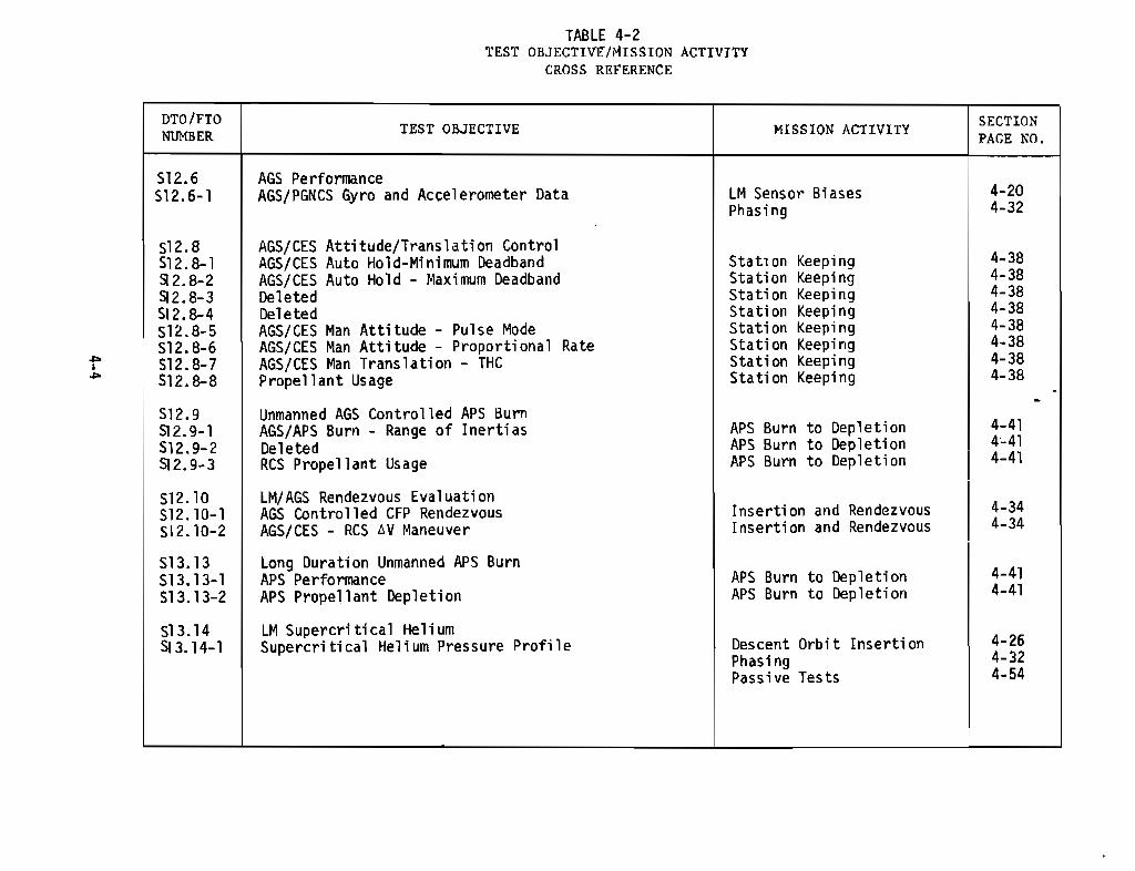
TABLE 4-2TEST OBJECTIVE/MISSION ACTIVITY
CROSS REFERENCE
DTO/FTO SECTIONNUMBER TEST OBJECTIVE MISSION ACTIVITY PAGE NO.
512.6 AGS Performance512.6-1 AGS/PGNCS Gyro and Accelerometer Data lM Sensor Biases 4-20
Phasing 4-32
512.8 AGS/CES Attitude/Translation Control512.8-1 AG5/CE5 Auto Hold-Minimum Deadband Stati on Keepi ng 4-38Q2. 8-2 AGS/CES Auto Hold - Maximum Deadband Station Keeping 4-38Q2.8-3 Deleted Stati on Keeping 4-38512.8-4 Deleted Stati on Keeping 4-38512.8-5 AG5/CE5 Man Attitude - Pulse Mode Stati on Keepi ng 4-38512.8-6 AGS/CES Man Attitude - Proportional Rate Stati on Keeping 4-38... 512.8-7 AG5/CE5 Man Translation - THC Station Keeping 4-38,... 512.8-8 Propellant Usage Station Keeping 4-38 .512.9
.Unmanned AGS Controlled APS Burn
512.9-1 AGS/APS Burn - Range of Inertias AP5 Burn to Depletion 4-41512.9-2 Deleted AP5 Burn to Depletion 4c41512.9-3 RCS Propellant Usage AP5 Burn to Depletion I
4-41
512.10 lM/AGS Rendezvous Evaluation512.10-1 AGS Controlled CFP Rendezvous Inserti on and Rendezvous 4-34512.10-2 AGS/CES - RCS !::.v Maneuver Insertion and Rendezvous 4-34
513.13 long Duration Unmanned APS Burn513.13-1 APS Performance AP5 Burn to Depletion 4-41513.13-2 APS Propellant Depletion AP5 Burn to Dep 1eti on 4-41
513.14 LM Supercriti ca1 He1i urn513.14-1 Supercritical Helium Pressure Profi 1e Descent Orbit Inserti on 4-26
Phas i ng 4-32Passive Tests 4-54

...,~
TABLE 4-2TEST OBJECTIVE/MISSION ACTIVITY
CROSS REFERENCE
DTO/FTO TEST OBJECTIVE MISSION ACTIVITY SECTIONNUMBER PAGE NO.
P16. 10 LM Steerable Antenna PerformanceP16.10-1 LM S-Band Steerable Antenna - Lunar Distance Telecommunications 4-42P16.10-2 Steerable Antenna Pattern Telecommunications 4-42P16.10-3 Steerable Antenna Procedure~ Telecommunications 4-42
Near lunar Surface 4-28516.12 LM Omni~Antennas Lunar Di stance516.12-1 LM Omni-Antennas lunar Distance Telecommunications 4-42
P16.14 Landing Radar TestP16.14-1 Landing Radar Lock-on Near-Lunar Surface 4-28PI6.14-2 Spurious Signal lock-on Descent Orbit Insertion 4-26
Phasing 4-32516.15 Rendezvous Radar Performance516.15-1 Maintain Lock at Maximum Range Insert; on and Rendezvous I 4-34516.15-2 Range Data Accuracy Insertion and Rendezvous 4-34516.15-3 Range Rate Data Accuracy Insertion and Rendezvous 4-34516.15-4 Tracking Angle Data Insertion and Rendezvous 4-34516.15-5 LM -X RCS Pl ume Effect on RR Insertion and Rendezvous 4-34
516.17 Rela~ Modes Voice/TM516.17-1 LM/M FN via 5-Band, LM/C5M via VHF, C5M/M5FN via S-Band Telecommunications 4-42516.17-2 LM/MSFN/C5M 5-Band Conference, MSFN Relay Telecommunications 4-42516.17-3 LM/C5M via V~F, C5M/MSFN via 5-Band,. C5M Relay Telecommunications 4-42516.17-4 LM Voice and LBR to C5M - C5M Oump Telecommunications 4-42516.17-5 LM/C5M via VHF, C5M/MSFN via 5-Band, LM Relay Telecommunications 4-42
520.46 Transposition/Docking/LM Ejection520.46-1 Trans/Dock/Ejection Demonstration Trans/Dock/Ejection 4-11520.46-2 Trans/Dock/Ejection Procedures and Time Trans/Dock/Ejecti on 4-11
P20.66 Crew Activities Lunar DistanceP20.66-1 Pre-LOI Through DOl Timeline Passive Tests 4-54P20.66-2 Lunar Orbi t Mi ss i on Procedures Passive Tests 4-54

TABLE 4-2TEST OBJECTIVE/MISSION ACTIVITY
CROSS REFERENCE
Descent Orbit Insertion 4-26Phasi ng 4-32Insert; on and Rendezvous 4-34Descent Orbit Insertion 4-26Phasing 4-32Insertion and Rendezvous 4-34
DTO/FTO TEST OBJECTIVENUMBER
520.77 VHF Ranging520.77-1 Accuracy of VHF Ranging During Rendezvous
P20.7B CSM/LM Rendezvous CapabilityP20.78-l LM Rendezvous Demons trati onP20.78-2 LM Rendezvous Procedures
520.79 Passive Thermal Control Modes520.79-1 PTC-Docked-Roll 0.1 Deg/5ec520.79-2 PTC-Docked- RollO. 3 De9/5ec... 520.79-3 PTC-C5M-Ro11 0.1 Deg/5ec,520.79-4 PTC-C5M-Ro11 0.3 Deg/5ecm
520.80 Ground Support Lunar Distance520.80-1 Ground Support Lunar Distance
520.82 PGNC5/AG5 Monitoring520.82-1 Ground Monitor of PGNCS/AGS
520.82-2 Crew Monitor of PGNC5/AG5
MISSION ACTIVITY
Insertion and Rendezvous
Insertion and RendezvousInsertion and RendezvousStation Keeping
Passive Thermal ControlPassive Thennal ControlPassive Thermal ControlPassive Thermal Contra)
Passive Tests
SECTIONPAGE NO.
4-34
4-344-344-38
4-144_144-144-14
4-54
520.83520.83-1520.83-2520. B3-3520.83-4520.83-5
LM Consumables Lunar OrbitElectrical LoadsWater and Oxygen RequirementsLiOH RequirementsPropellant RequirementsFood Requi rements
Lm Cons umab1esLM ConsumablesLM Cons umab 1esLM ConsumablesLM Consumables
4-534-534-53'4-534-53
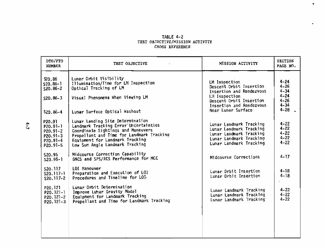
DTD/FTONUMBER
TABLE 4-2TEST OBJECTIVE/MISSION ACTIVITY
CROSS REFERENCE
TEST OBJECTIVE MISSION ACTIVITYSECTIONPAGE NO.
•
...,~
520.86520.86-1520.86-2
520.86-3
520.86-4
P20.91P20.91-1P20.91-2P20.91-3P20.91-4P20.91-5
520.95520.95-1
520.117520.117-1520.117-2
P20.121P20.121-1P20.121-2P20.121-3
lunar Orbit VisibilityIllumination/Time for LM InspectionOptical Tracking of LM
Visual Phenomena When Viewing LM
Lunar Surface Optical Washout
Lunar Landing Site DeterminationLandmark Track; n9 Error- Uncertai nti esCoordinate Sightings and ManeuversPropellant and Time for Landmark TrackingEquipment for Landmark TrackingLow Sun Angle Landmark Tracking
Midcourse Correction C~pab;lity
GNC5 and 5P5/RC5 Performance for MCC
lOI r~aneuver
Preparation and Execution of LOIProcedures and Timeline for LOI.
Lunar Orbit DeterminationImprove LUhar Gravity ModelEquipment for Landmark TrackingPropellant and Time for Landmark Tracking
LH InspectionDescent Orbit InsertionInsertion and RendezvousL:" Inspecti onDescent Orbit InsertionInsertion and RendezvousNear Lunar Surface
Lunar Landmark TrackingLunar Landmark TrackingLunar Landmark TrackingLunar Landmark TrackingLunar Landmark Tracking
Midcourse Corrections
Lunar Orbit InsertionLunar Orbit Insertion
Lunar Landmark TrackingLunar Landmark TrackingLunar Landmark Tracking
4-244-264-344-244-264-344-28 •
4-224-224-224-224-22
4-17
4-184-18
4-224-224-22
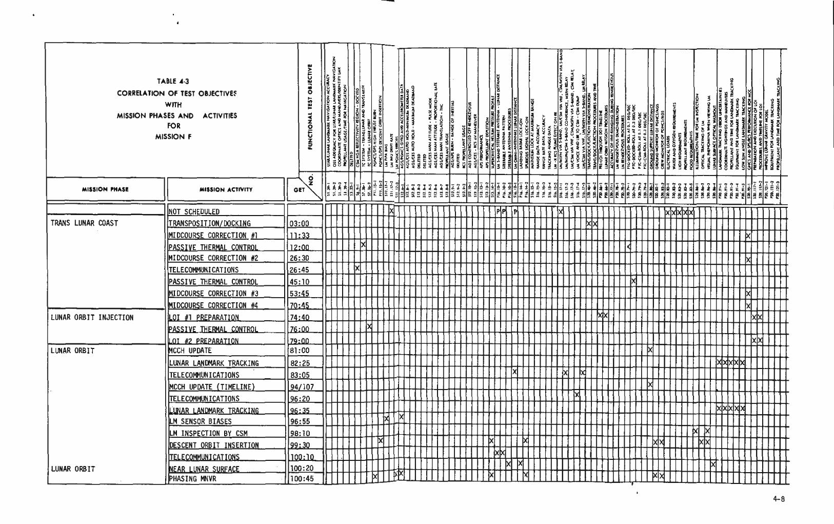

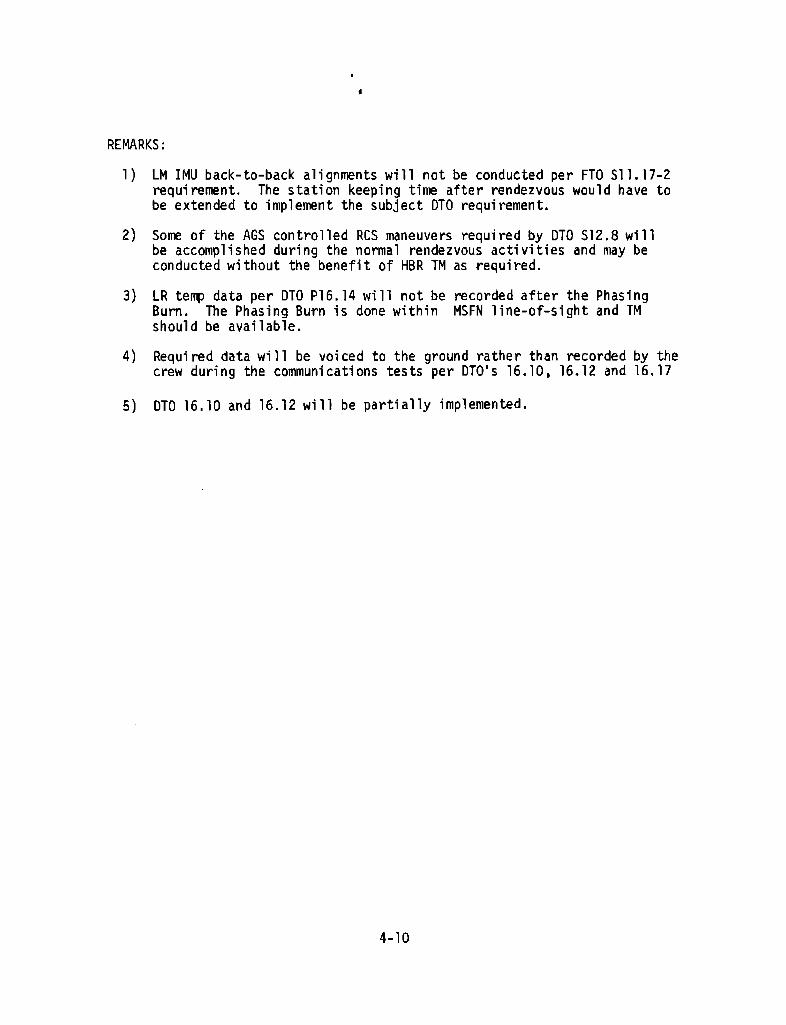
•
REMARKS:
1) LM IMU back-to-back alignments will not be conducted per FTO 511.17-2requirement. The station keeping time after rendezvous would have tobe extended to implement the subject DTO requirement.
2) Salre of the AGS controlled Res maneuvers required by DrO 512.8 willbe accomplished during the normal rendezvous activities and may beconducted without the benefit of HBR TM as requi red.
3) LR temp data per oro P16. 14 wi 11 not be recorded after the Phas; ngBurn. The Phasing Burn is done within MSFN line-of-sight and TMshould be available.
4) Requi red data wi 11 be VOl ced to the ground rather than recorded by thecrew during the communications tests per DID's 16.10. 16.12 and 16.17
5) DTD 16.10 and 16.12 will be partially implemented.
4-10
·TRANSPOSITIO~/OOCKING/EJECTION
A. TEST OBJECTIVES
520.46-1 Transpos i ti on/Dock; ngjEjecti on Demons trati on520.46-2 Transposition/Docking/Ejection Procedures and T;meline
B. TEST REQUIREMENTS
1. Accomplish transposition, aocking and LM ejection. [20.46]
2. Foll""ing S-IVB TLI burn and in sunlight. [20.46J
3. S-IVB attitude and maximum limit cycle rates during docking andejection will be in accordance with the Apollo Inter-Center ICDSOM90505. "Flight Mechanics Panel Interface Control Documentfor the Apollo-Saturn 505". Paragraph mo. [20.46J
4. S-IVB in inertial hold. [20.46J
5. lighting constraints as specified in MSCjMSFC Trajectory DocumentNo. TBD, "Joint Operational Mission Constraints" for Mission F willbe met. [20.46J
6. Photograph view through right hand rendezvous window from end oftransposition until initial probe and drogue capture latching using16 ri1n sequence camera with 18 Il111 lens and color film at 6 framesper second. [20.46J
7. MSFN coverage required for entire test. [20~46]
C. TEST PROCEOURES/CHECKLISTS
1. CSM-AOH lILM Interface"
2. FCAC "Separati on Through Wit"hdrawa 111, L9- 1 through 3
D. DATA REQUIREMENTS
1. Flight Crew Reports/Logs
a. Conrrent on CSM handl i ng characteri s ti cs duri n9 transpos i ti on anddocking. [20.46J (M)
b. Conment on adequacy of docking alignment target on the LM.[20.46J (M)
c. Comment on vehicle dynamics of CSM/LM during ejection from theS-IVB. [20.46J (M)
d. Connent on adequacy of attitude control and s tabil ity characteri sti csof S-IVB prior to, during and immediately after the separation andejection of the LM from the S-IVB/SLA. [20.46J (M)
4-11

e. Comment on any adverse effects of the SM RCS plumes on astronautvisibility or on S-IVB stability.[20.46] (HO)
f. Comment on adequacy of sunlight and CSM docking lights. [20.46] (HO)
g. Comment on adequacy of contact with ground operational facilities.[20.46] (M)
Radial, angular and rotational ali~nment at time of initialprobe and drogue contact.[20.46] (I~) .
h. Log
(1) GET when transposition initiated.[20.46] (M)
( 2)
(3) Axial, radial and angular relative velocities at time of initialprobe and drogue contact. [20.46] (M)
(4) After docking, the included angle between the CM and LM Z-Xplanes, measured about the CM X axis.[20.46] (M)
(5) GET when CSM/LM ejection was completed. [20.46] (M)
(6) Separation rate during ejection. [20.46] (HO)
2. Photographs
a. Photos through right hand rendezvous window from end of CSM transposition until initial probe and drogue capture latching.[20.46] (HO)
b. Log film mag, footage in Photographic Log. [20.46] (HO)
3. Ground Support
a. CSM TM HBR.[20.46] (HO)
b. CSM TM LBR.[20.46] (M)
c. LVOC TM Oata.[20.46] (M)
d. Fli ght Di rector will assess ground operat1 ona1 support and determineits adequacy. [20.46] (M)
4-12

DOCKING VELOCITY AND ALIGNMENT•820.46 Transposition/Docking/LM Ejection
REWMAN O~T1CAl
ALIGNMENT SIGHTS'ANDO~F C~OSS
(CSM-ACflVE DOCKINGAlIGNMlNT TARGET)
LM COA5 LINEOF SIGH T ~05T
PITCMOVU POSITION'
STANDOFF CROSS ANDALIGNMENT SUIPS
(LM • ACTIVE DOCKINGALIGNMENT TARGETl
RECORD:
Conta
GET Trans 0
GET CSM/LM E ection Com leted
1---+-~'-.1.:!~~~~~~__~f--+_~~S.l-k(lia1~__-I
Rota tiona! () /Se_~~J,5.!U~u......---_~~t-...J.......,J......lo.:::..":;O,.:.L..-=~
Final'::: Between CSM -Z and LM +Z A
FIGURE 4-1 DOCKING VELOCITY AND ALIGNMENT
4-13
PASSIVE ,THERMAL CONTROL MODES
A. TEST OBJECTIVES
57.26-1 Te System for Translunar and Transearth Flight520.79-1 PTC-Docked-Ro11 0.1 DEG/SEC520.79-2 PTC-Docked-Roll 0.3 DEG/SEC520.79-3 PTC-CSM-Roll 0.1 DEG/SEC520.79-4 PTC-CSM-Roll 0.3 DEG/SEC
B. TEST REQUIREMENTS
1. At least four uninterrupted hours for each PTe Mode. [20.79-1,2,3,4]
2. MSFN Coverage. [7.26,20.79-1,2,3,4]
3. Roll Modes - Orient the SIC to place the X axis perpendicular tothe LOS to the sun within +5 degrees attitude deadband. Roll aboutthe X axis at the rate and-within the attitude deadband specifiedbelow:
a. 0.1 DEG/SEC roll, pitch & yaw D/B :.200
(1 ) Trans 1unar - Docked CSM/LM [20.79-1]
(2) Transearth - CSM only [20.79-3]
b. 0.3 DEG/SEC roll, pitch & yaw D/B +300
(1) Trans 1unar - Docked CSM/ LM [20.79-2]
(2) Transearth - CSM only [20.79-3]
4. Roll jets should be disabled when the required roll rate is established&the computer procedure for PTe should be terminated before re-enablingthe roll jets. [20.79-1,2,3,4]
C. TEST PROCEDURES/CHECKLISTS
1. CSM AOH 4.10.2.9 Passive Thermal Control
2. FCAC, IlPass; ve Therma 1 Control", G2-95
D. DATA REQUIREMENTS
1. Flight Crew Reports/Logs
a. Voice record of sequence of events. [20.79-1,2,3.4] (M)
b. Comment on ease of operation and adequacy of procedures toaccomplish required communications. [20.79] (M)
4-14
c. Cornrrent on preferred technique for initiating and maintainingPTC. [20.79-1,2,3,4] (M)
2. Ground Support
a. CSM TM HBR.[7.26, 20.79-1, 2,3,4] (M)
b. CSM TM LBR. [7.26,20.79-1,2,3,4] (M)
c. BET. [20.79-1, 2, 3, 4] (M)
4-15
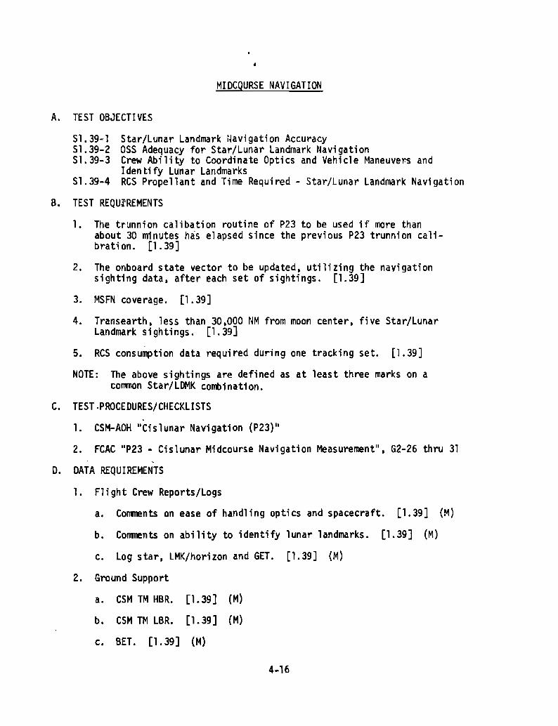
MIDCQURSE NAVIGATION
A. TEST OBJECT! VES
51.39-1 Star/Lunar Landmark ~avigat;on Accuracy51.39-2 ass Adequacy for Star/Lunar landmark Navigation51.39-3 Crew Ability to Coordinate Optics and Vehicle Maneuvers and
Iden tHy Lunar Landmarks51.39-4 ReS Propellant and Time Required - Star/Lunar landmark Navigation
B. TEST REQU,'REMENTS
1. The trunnion calibation routine of P23 to be used if more thanabout 30 minutes has elapsed since the previous P23 trunnion calibration. [1.39]
2. The onboard state vector to be updated. utilizing the navigationsighting data. after each set of sightings. [1.39]
3. MSFN coverage. [1.39]
4. Transearth, less than 30.000 NM from moon center, five Star/LunarLandmark si9htings. [1.39]
5. ReS consumption data required during one tracking set. [1.39]
NOTE: The above sightings are defined as at least three marks on acommon Star/LDMK combination.
C. TEST ,PROCEDURES/CHECKLISTS
1. CSM-AOH "Cislunar Navigation {P23)11
2. FCAC "p23 - Cislunar Midcourse Navigation Measurenent", G2-26 thru 31
D. DATA REQUIREMENTS
1. Flight Crew Reports/Logs
a. Comments on ease of handling optics and spacecraft. [1.39] (M)
b. Comments on ability to identify lunar landmarks. [1.39] (M)
c. Log star, LMK/horizon and GET. [1.39] (M)
2. Ground Support
a. CSM TM HBR. [1. 39] (M)
b. CSM TM LBR. [1. 39] (M)
c. BET. [1.39] (M)
4-16
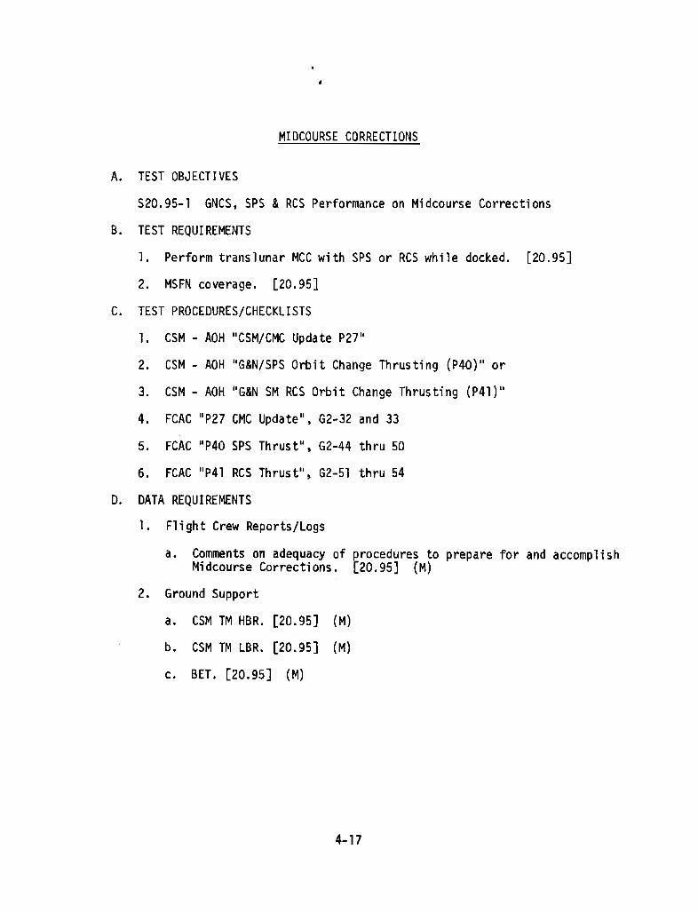
MIDCOURSE CORRECTIONS
A. TEST OBJECTIVES
520.95-1 GNCS, SPS &Res Performance on Midcourse Corrections
B. TEST REQUIREMENTS
1. Perform translunar MCC with SPS or RCS while docked. [20.95]
2. MSFN coverage. [20.95]
C. TEST PROCEDURES/CHECKLISTS
1. CSM - AOH "CSM/CMC Update P27"
2. CSM - AOH "G&N/SPS Orbit Change Thrusting (P40)" or
3. CSM - AOH "G&N SM ReS Orbit Change Thrusting (P4l) "
4. FCAC "p27 CMe Update". G2-32 and 33
5. FCAC IIp40 SPS Thrust". G2-44 thru 50
6. FCAC "p41 ReS Thrust", G2-51 thru 54
D. DATA REQUIREMENTS
1. Flight Crew Reports/logs
a. Comments on adequacy of erocedures to prepare for and accomplishMidcourse Corrections. l20.95] (M)
2. Ground Support
a. CSM TM HBR. [20.95] (M)
b. CSM TM LBR. [20.95] (M)
c. BET. [20.95] (M)
4-17

LUNAR ORBIT INSERTION
A. TEST OBJECTIVES
520.117-1 Crew/Spacecraft/MSFN Preparation and Execution of LO! Maneuver520.117-2 Procedures and Timeline Adequacy for LO! Maneuver
B. TEST REQUIREMENTS
1. SPS operation to insert the docked CSMjlM into lunar orbit in twostages as follows; [20.117]
a. The fir5t burn of approximately 352 seconds in duration willinsert the CSM into a 60 x 170 NM orbit.
b. The second burn of approximately 10 seconds in duration willcircularize the orbit to 60 NM.
2. DSE recording 40 seconds before, during and 2 minutes after both burns.[20.117]
3. IMU realignment performed as soon pr·;or to lOI-l as practicable.[20.117]
4. MSFN tracking prior to LOS before LO!. [20.117]
5. MSFN record dumped DSE data at AOS after LO!. [20.117]
C. TEST PROCEDURES/CHECKLISTS
1. CSM - AOH "G&N SPS Orbit Change Thrusting (P40)"
2. FCAC "SPS Thrusting (P40)", G2-44 thru 50
D. DATA REQUIREMENTS
1. F1 i ght Crew Reports/Logs
a. Procedura 1 and/or ti me 1i ne diffi cult; es or inadequaci es. [20.117] (M)
b. Feasibility of monitoring abort parameters on FOAI's. [20.117] (M)
c. Adequac~ of contact with[20.117J (HD)
ground operational support facilities.
2. Ground Support
a. CSM TM LBR from DSE after AOS. [20.117] (M)
4-1B

b. CSM TM HBR from OSE after ADS. [20.117] (HO)
c. BET before LOS and after ADS. [20.117] (M)
d. Flight Director's reports of procedural and/or timeline difficultiesor inadequacies. [20.117] (M)
4-19

LM SENSOR BIASES
A. TEST OBJECTIVES
Sll.17-1 LM PGNCS PIPA Bias During Coasting FlightS12.6-1 AGS Gyro Bias and Accelerometer Data and PGNCS Gyro Data During
Drifting Flight
B. TEST REQUI REMENTS
1. MSFN collection of LM PGNCS PIPA bias data at least three times duringthe mission using uninterrupted TM for at least five minute intervalsas follows: [11.17]
a. Dur1ng LM systems activation and checkout.
b. During LM activation prior to rendezvous.
c. After LM rendezvous.
2. IMU and LGC on [11.17, RCS off. [11.17, 12.6]
3. MSFN collection of AGS gyro bias and accelerometer data and PGNCS gyrodata during drifting flight using uninterrupted n~ for at least fiveminutes. [12.6]
4. MSFN coverage. [11.17, 12.6]
C. DATA REQUIREMENTS
1. LM TM HBR•. [11.17 ,12.6] (M)
4-20

LM IMU ALIGNMENT
A. TEST OBJECTIVES
Sl1.17-2 PGNCS IRIG Drift Rates During Coasting Flight
B. TEST REQUI REMENTS
1. One set of back-to-back lM H1U ali gnments duri ng caas ti ng fl i ght.[11. 17] N. !.
2. At least one hour between mu alignments with no intervening thrustmaneuvers. [11.17] I:'!.
'3. PGNCS powered up between alignments in a set. [11.17]
4. MSFN coverage. [11. 17]
C. TEST PROCEDURES/CHECKLISTS
1. LM-AOH "IMU Orientation Determination Program (P51}11 or
2. LM AOH "IMU Realign (P52)"
3. FeAC "PSl - IMU Orientation" or
4. FeAC "p52 - IMU Realign"
D. DATA REQUIREMENTS
LM TM HBR following the second alignment of each set of alignments.[11.17] (M) N.!.
4-21
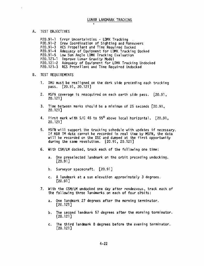
LUNAR LANDMARK TRACKING
A. TEST OBJECTIVES
P20.91-1 Error Uncertainties - LDMK Tracking .P20.91-2 Crew Coordination of Sighting and ManeuversP20.91-3 ReS Propellant and Time Required DockedP20.91-4 Adequacy of Equipment for LDMK Tracking DockedP20.91-5 Low Sun Angle lDMK Tracking EvaluationP20. 121-' Improve Lunar Grav; ty ModelP20.121-2 Adequacy of Equipment for lDMK Tracking UndockedP20.121-3 ReS Propellant and Time Required Undecked
B. TEST REQUI REMENTS
l. IMU must be realigned on the dark side preceding each trackingpass. [20.91, 20.121]
2. MSFN coverage is reacquired on each earth side pass. [20.91,20.121]
3. Time between marks should be a minimum of 25 seconds [20.91,20.121]
4. First mark with SIC 45 to 55° above local horizontal. [20.91,20.121]
5. MSFN will support the tracking schedule with updates if necessary.If HBR TM data cannot be recorded in real time by MSFN, the datawi 11 be recorded on the DSE and dumped at the fi rst opportuni tyduring the same revolution. [20.91, 20.121]
6. Wi th CSM/lM docked, track each of the following one time:
a. One preselected landmark on the orbit preceding undocking.[20.91]
b. Surveyor spacecraft. [20.91]
c. A landmark at a sun elevation approximately 3 degrees.[20.91 ]
7. Wi th the CSM/lM undocked one day after rendezvous, track each ofthe following three landmarks on each of four orbits:
a. One landmark 27 degrees after the morning terminator.[20.121]
b. The second landmark 57 degrees after the morning terminator.[20.121]
c. The third landmark 8 degrees before the evening terminator.[20.121]
4-22

Photograph the above laQdmark through the SIC window using thehighest resolution camera/lens combination. [20.121]
C. TEST PROCEOURES/CHECKLISTS
1. CSM-AOH "Orbital Navigation (P22)"
2. FCAC "p22 Orbital Navigation;' G2-18 thru 24
O. DATA REQUIREMENTS
1. F1 i ght Crew Reports/Logs
a. Conrnents on ease of handling optics and spacecraft. [20.91, 20.121] (M)
b. Comments on minimum sun elevation angle for lunar lDMK tracking.[20.91] (M)
c. Comments on the lunar landmark recognition on each successiverevolution. [20.91,20.121] (M)
d. "Landmark Tracking Log" (Flight Plan) [20.91, 20.121] (M)
e. Photographs of Landmarks. [20.121] (HO)
2. Ground Support
a. BET. [20.91] (M)
b. CSM TM HBR from OSE after AOS. [20.91] (M) [20.121] (HO)
c. CSM TM LBR from OSE after AOS. [20.91, 20.121] (M)
4-23
LM INSPECTION BY CSM
A. TEST OBJECTIVES
520.86-1 Illumination and Time Required for CSM Inspection of LMin lunar Orbit
520.86-3 Visual Phenomena Observed from CSM During lM Inspectionand LM Descent and Ascent
B. TEST REQUIREMENTS
1. Undocked. [20.86]
2. CSM pilot visually inspects LM in lunar orbit prior to 001. [20.86]
C. DATA REQUIREMENTS
1. CSM pilot comment on illumination of LM and any unexpected visualphenomena during LM inspection. [20.86] (M)
2. CSM pilot corrment on adequacy of time allotted for LM inspection.[20.86] (HOl
4-24

CMP Maintain inertial attitude hold in lowrate, wide deadband.
CDR When clear of CSM by 40 to SO feet, nullseparation velocity and maintain stationkeeping distance, inertial hold.
Yaw right 1200 and pitch + 900 •
For inspection, yaw 3600 at 2 deg/secclockwise.
LMP Inspect the CM probe extension when inview.
CMP Inspect the following LM components throughthe CDR's window:
Landing GearDrogue
- 1lescent Engine NozzleS-Band AntennaThermal Shields &Surfaces
4-25
DESCE~T ORBIT INSERTION
A. TEST OBJECTIVES·
Pl1.15-2513.14-1516.14-2
S20.B2-1520.82-2520.86-2
520.86-3
Capabil ity of PGNCS to .Execute the 001 ManeuversSupercritical Helium Pressure ProfileNo Ve' acity / Alti meter Frequency Tracker lock On to Spur; ousDoppler SignalsGround Monitoring of LM PG~CS/AGS
Crew Monitoring of LM PG~CS/AGS
Optical Tracking of LM by CSM Pilot During LM Descent to50,000 FeetUnusual Visual Phenomena Observed by the CSM Pilot DuringLM Descent to 50,000 Feet
B. TEST REQUIREMENTS
1. 001, including orientation, to be performed under PGNC$ control withDPS. [11 .. 15]
2. Burn profile to be the same as that planned for the LLM. (HD)[11.15]
3. CSM pilot to track LM with the SXT. [20.86]
4. DSE on HBR while taking marks and processing data. [20.86]
5. VHF ranging required during tracking. [20.82, 20.B6]
6. LR. to be operated during DOllOPS burn with antenna in position 1. [16.14]
7. LM crew di s'p lays, procedures and computati ana' ai ds sha 11 be used ;nmonitoring LM PGNCS/AGS performance to determine if guidance should betransferred at any point during the burn. [20.aa]
C. TEST PROCEDURES/CHECKLISTS
1. LM AOH paragraph 4.10;1, "DPS Thrust Program (P40) with AGS Follow-Up/In Control U
2. CSM AOH paragraph 4.6.2, "CSM Rendezvous Navigation'1, steps 1 through 7
3. FCAC, "P20 Rendezvous Navigation", G2-l5
4. LM AOH paragraph 4.6.3.2, "Landing Radar Power Uplt
D. DATA REQUIREME~TS
1. Flight Crew Reports/Logs
a. Confirm that false LR lock did not occur. [16.14] (HDl
4-26
b. Comments on adequacy of procedures necessary to accomplishDOl. [11.15] (M)
the
c. COlIITIents on PGNCS performance during 001. [11.15] (HO)
d. CSM pilot corrments on lM tracking with SXT during LM descentincluding GET of loss of view. [20.86] (HO)
e. Comments on any significant unexpected visual phenomena.[20.86] (M)
f. Record LR antenna te"",erature at end of DPS burn and two minuteslater. [16.14] (HO)
g. Conments on adequacy of LM displays. onboard procedures andonboard charts used to perform ~u;dance monitor functions during1unar orbi t operati ons. [20.82 J (M)
h. Conments on adequacy and clarity of MSFN data concerning PGNCS/AGS residuals during lunar orbit operations as furnished by voicelink to the LM. [20.82] (M)
i. Comments on adequacy and c1 ari ty of GNCS and VHF deri ved rangerate data as furnished by voice link from" the eM to the lM.[20.82] (M)
2. Ground Support
a. LM TM LBR [11.15, 13.4-1, 16.14] (M), recorded on OSE
b. BET LM [11.15, 20.86] (M); BET CSMfLM [20.82] (HO); [20.86] (M)
c. Flight Director's reports of timeline and/or procedural difficulties.(M)
d. Real time S-band ranging data from LM. [20.82, 20.86] (M)
e. Real time S-band ranging data from CSM. [20.82, 20.86] (HO)
f. MSFN doppler data during powered phases. [20.82, 20.86] (M)
g. CSM TM HBR. (20.86] (M)
4-27
NEAR LUNA~ SURFACE ACTIVITY
A. TEST OBJECTIVES
P16.10~3 Evaluate Steerable Antenna During Simulated "Gil Descent ManeuversP16.14-1 Lock on for Landing Radar Beams and Generation of Velocity/Altitude
Data520.86-4 Extent/Severity of Washout When Viewing the Lunar Surface from
the LM
B. TEST REQUIREMENTS
1. Landing radar to be operated during the 200 sec. period prior to andduring the·200 sec. peri-od after pericynthion.
a. LR antenna in position 2. [16.14]
b. Constant pitch rotation rate of .052 deg/sec. (lunar Orb. Rate).[16.14]
c. lM +X axis vertical, +Z axis forward, a degrees yaw. [16.14]
d. Roll angle 0 (tl) degree. [16.14]
e. Altitude above lunar surface not to exceed 10 NM. [16.14]
f. Steerable antenna operational procedures to be exercised during1800 roll face up and gOo pitch up to local vertical. [16.10]
2. Commander to observe lunar surface near point of closest approach.[20. B6D
C. TEST PROCEDURES/CHECKLISTS
1. LM AOH paragraph 4.6.3.2, lILanding Radar Power~Up"
2. LM AOH paragraph 4.6.3.4, lILanding Radar Checkout ll
D. DATA REQUIREMENTS
1. Flight Crew Reports/Logs
a. Commander comments on extent and severity of observed surfacewashout. [20.86] (M)
b. LPD coordinates defining the area of loss of useful detailand time of observation. [20.86] (M)
c. Data TBD for the steerab1e antenna test. [16.10] (M)
4-28

2. Ground Support
a. BET [16.14J (M)
b. LM TM HBR [16.14J (M)
c. LM TM LBR [16.14J (M)
d. MSFN records of received S-band signal strength. [16.10J (M)
4-29

•
Lo
.---.-- - _.-AR LUNAR SURFACE ACTIVITY
6.10 LM/MSFN Comm. Lunar Distance6.14 Landing Radar0.86 Lunar Surface Washout.
QUIRED
R Powered Uprdeal - Orb Rate
Steerable Antenna - MSFN AcquisitionTo - PericynthionAntenna Position - 2
OCEDURE
To -900 SeC. Acquire MSFN (Steerable Antenna)Yaw Right 1800 (Face Down to Face Up)Pitch Up to Within 10° of Lbcal VerticalStart Orbit Rate ~ .052 Deg/Sec Pitch DownTo -400 Sec, Checkout LRTo -200 Sec, Pitch Down 100 To Local VerticalObserve Lunar Surface Through Front WindowUse LPn Markings to Designate Washout AreaRecord Washout Area Coordinates and Time Observed
TO DEG. RRS.
TO AHEAD X MIN.-BEHIND X SEC.
ITo +200 Sec, Pitch Down 900 (Face Down)
Observe Landing Site (photographs HD)Terminate LR TestTerminate Orbit RateTo +600 sec, Mnvr to Phasing Burn Attitude
- --
NE
PR
RE
P1P152
4-30
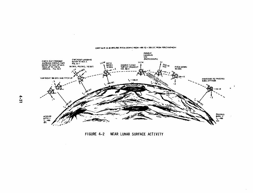
ORBIT un (0.05 DEGt.;EC PITCIl DOWN) FROM -400 TO .200 ,EC fll()IA PUICYNnllON
~I
W-
CHECK OUT STUIAIUANTfNNA DUlliNG fACEDO'IfN TO FACE UP ANDPIlCH UP 10 lOCAl.IlERTICAL P16.1003
ACOUIREMSFN :::;To ·900SliC
FIGURE 4-2
OBSERIIElANDINGSITElPHOTOGRAPIi)
LV/-</(
OBSERVE lUNAR tSUIlFAa WASHOUTS20.~
NEAR LUNAR SURFACE ACTIVITY
PilCH DOWN
MANElNU TO PIIASING...... .... BlJlN A,1ITUDf
PHASINGtuRN ~
10 +900SEC
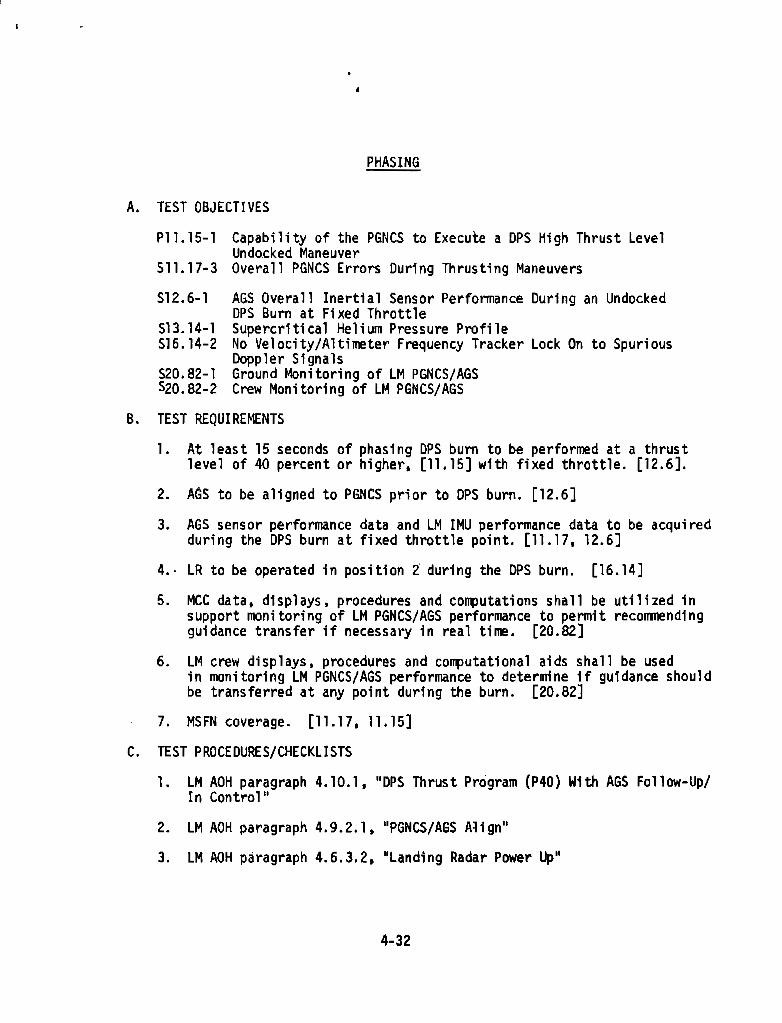
,
PHASING
A. TEST OBJECTIVES
Pll.15-1 Capability of the PGNCS to Execute a OPS High Thrust LevelUndncked Maneuver
511.17-3 Overall PGNCS Errors During Thrusting Maneuvers
512.6-1 AGS Overall Inertial Sensor Performance During an UndockedCPS Burn at Fi xed Throttle
513.14-1 Supercritical Helium Pressure Profile516.14-2 No Velocity/Altimeter Frequency Tracker Lock On to Spurious
Ooppler SignalsS20.82-1 Ground Monitoring of LM PGNCS/AGSS20.B2-2 Crew Monitoring of LM PGNCS/AGS
B. TEST REQUIREMENTS
1. At least 15 seconds of phasing DPS burn to be performed at a thrustlevel of 40 percent or higher, [11.15] with fixed throttle. [12.6].
2. AGS to be aligned to PGNCS prior to CPS burn. [12.6]
3. AGS sensor performance data and LM IMU performance data to be acqu; redduring the CPS burn at fixed throttle point. [11.17, 12.6]
4.· LR to be operated in position 2 during the CPS burn. [16.14]
5. MeC data. displays, procedures and computations shall be utilized insupport monitoring of LM PGNCS/AGS performance to permit recommendingguidance transfer if necessary in real time. [20.82]
6. LM crew displays. procedures and computational aids shall be usedin monitoring LM PGNCS/AGS performance ta determine if guidance shouldbe transferred at any point during the burn. [20.B2]
7. MSFN coverage. [11.17,11.15]
C. TEST PROCEOURES/CHECKLISTS
1. LM AOH paragraph 4.10.1, "CPS Thrust Program (P40) With AGS Follow-Up/In Cantrall!
2. LM AOH paragraph 4.9.2.1, "PGNCS/AGS Align"
3. lM AOH paragraph 4.6.3.2, "Landing Radar Power Up"
4-32
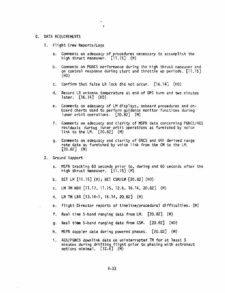
,
O. DATA REQUIREMENTS
1. Fl; ght Crew Reports/Logs
a. Comments on adequacy of procedures necessary to accofllJlish thehigh thrust maneuver. [11.15] (M)
b. Comments on PGNCS performance during the high thrust maneuver andon control response during start and throttle up periods. [11.15](HO)
c. Confirm that false LR lock did not occur. [16.14] (HO)
d. Record LR antenna temperature at end of DPS burn and two m; nuteslater. [16.14] (HO)
e. Conments on adequacy of LM displays, onboard procedures and onboard charts used to perform guidance monitor functions duringlunar orbit operations. [20.82] (M)
f. Comments on adequacy and clarity of MSFN data concerning PGNCS/AGSresiduals during lunar orbit operations as furnished by voicelink to the LM. [20.82] (M)
g. Comments on adequacy and clarity of GNCS and VHF derived rangerate data as furnished by voice link -from the CM to the LM.[20.82] (M)
2. Ground Support
a. MSFN tracking 60 seconds prior to. during and 60 seconds after thehigh thrust maneuver. [11.15] (M)
b. BET LM [11.15] (M); BET CSM/LM [20.82] (HO)
c. LM TM HBR [11.17,11.15,12.6,16.14,20.82] (M)
d. LM TM LBR [13.14-1, 16.14,20.82] (M)
e. Flight Director reports of timeline/procedural difficulties. (M)
f.
g.
h.
Real time S-band ranging data from LM. [20.82] (M)
Real time S-band ranging data from CSM. [20.82] (HO)
MSFN doppler data during powered phases. [20.82] (M)
i. AGS/PGNCS downlink data on uninterrupted TM for at least 5minutes during drifting flight prior to phasing with astronautmotions minimal. [12.6] (M)
4-33
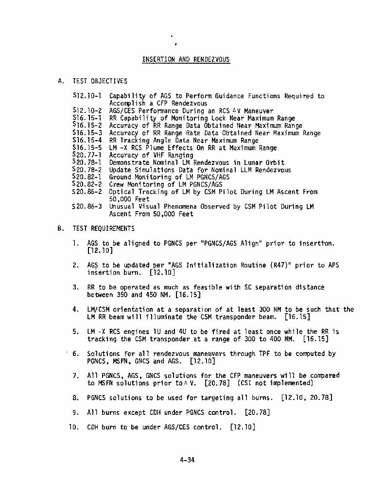
INSERTION AND RENDEZVOUS
A. TEST OBJECTIVES
512.10-1 Capability of AGS to Perform Guidance Functions Required toAccornp1; sh a CFP Rendezvous
512.10-2 AGS/CES Perfonnance During an ReS D.V Maneuver516. 15~1 RR Capability of Monitoring Lock Near Maximum Range516.15-2 Accuracy of RR Range Data Obtained Near Maximum Range516.15-3 Accuracy of RR Range Rate Data Obtained Near Maximum Range516.15·4 RR Tracking Angle Data Near Maximum RangeS16.15-5 LM -X RCS Plume Effects On RR at Maximum RangeS20.77-1 Accuracy of VHF Ranging520.78-1 Demonstrate Nominal lM Rendezvous in Lunar Orbit520.78-2 Update Simulations Data for Nominal LLM RendezvousS20.B2-1 Ground Monitoring of LM PGNCS/AGSS20.B2-2 Crew Monitoring of LM PGNCS/AGS5'20.86-2 Optlcal Tracking of LM by CSM Pilot During LM Ascent From
50,000 Feet520.86-3 Unusual Visual Phenomena Observed by CSM Pilot During LM
Ascent From 50,000 Feet
B. TEST REQUIREMENTS
1. AGS to be aligned to PGNCS per uPGNCS/AGS Align" prior to inserti·on.[12.10]
2. AGS to be updated per IlAGS Initialization Routine (R47)11 prior to APSinsertion burn. [12.10]
3. RR to be operated as much as feasible with SC separation distancebetween 350 and 450 NM. [16.15]
4. lM/CSM orientation at a separation of at least 300 NM to be such that theLM RR beam will illuminate tRe CSM transponder beam. [16.15]
5. lM -x RCS engines lU and 4U to be fi.red at least once while the RR istracking the CSM transponder at a range of 300 to 400 NM. [16.15]
6. Solutions for all rendezvous maneuvers through TPF to be computed byPGNCS, MSFN, GNCS and AGS. [12.10]
7. All PGNCS. AGS, GNCS sol uti ons for the CFP maneuvers wi 11 be comparedto MSFN solutions prior toll V. [20.78] (CSI not implemented)
8. PGNCS solutions to be used for targeting all burns. [12.10, 20.7B]
9. All burns except CDH under PGNCS control. [20.7B]
10. CDH burn to be under AGS/CES control. [12.10]
4-34
11. AGS state vector to be updated every 3 minutes from CDH +10 minutestoTPI. [12.10]
12. Prior to TPI, AGS to be updated for the last tiTre. [12.10]
13. AGS wi 11 not be used as a reference pas t TPI. [12.10]
14. MCC data, displays, procedures and computations shall be utilized insupport monitoring of LM PGNCSjAGS performance to permit recommendingguidance transfer if necessary in real time. [20.82]
used inshould
lM crew displays, procedures and computational aids shall bemonitoring LM PGNCSjAGS performance to determine if guidancebe transferred at any point during the burn. [20.82J
16. CSM pilot to track LM with SXT from insertion through Rendezvous.[20.86]
15.
17. DSE on H8R for all burns conducted during MSFN LOS. [20.77]
18. VHF ranging required during trackinQ except during DPSjAPS burnsconducted outside the MSFN 1ine-of-sight. [20.77, 20.82, 20.86]
C. TEST PROCEDURES/CHECKLISTS
1. LM AOH paragraph 4.9.2.1, "PGNCS/AGS Align"
2. LM AOH paragraph 4.6.1.18, "AGS Initialization Routine (R47)"
3. LM AOH paragragh 4.8.2.2, nAGS Manual Rendezvous Radar LM StateVector Update"
4. CSM AOH paragraph 4.6, lIRendezvous"
5. LM AOH paragraph 4.6.3.1, "Rendezvous Radar Power Up"
6. CSM AOH paragraph 4.7.6.9, "Rendezvous Transponder Activation andSelf Test"
7. MSC Document, IIlM Rendezvous Procedures F Mission ll
8. FCAC, "Pl7 TPI Search or P77 LM TPI Search", G2-14
9. FCAC, lIp20 Rendezvous Navigation ll, G2-15
10. FCAC,"P34 TPI Prethrust (P74 LM)", G2-38
11. FCAC, "P35 TPM Prethrust (P75 LM)", G2-39
12. FCAC, "P38 SOR Targeting (P78 LM)", G2-42
4-35
13. FCAC. "p39 Stable Orbit Mid (P79 LM)". G2-43
14. FCAC. "V83 Rndz Parameter Display #1". G2-73
15. FCAC. IIV8S Rndz Parameter Display #2", G2-74
16. FCAC. "V90 Out of Plane Oispl ay ll, G2-75
O. DATA REQUIREMENTS
1. Flight Crew Reports/Logs
a. COl1Tl1en~s on adequacy, of AGSjCES procedures and performanceduring the COH burn. [12.10] (HD)
b. Comments on ability to maintain RR lock at a range greater than350 NM. [16.15] (HD)
c. GET t 1 minute at any deliberate break of RR lock. [16.15] (M)
d. Min/Max transponder AGe voltage readings during LM -x ReSfirings. [16.15] (Hol
e. Comnents on planned and actual crew procedures used. '[20.78] (M)
f. Comments on AGS & RR performance. [20.78] (M)
g. Comments on PGNCS & RR performance. [20.78] (M)
h. Comments on single crewmember LM rendezvous capability.[20.78] (M)
i. COllll'<!nts on usefulness of CSM rendezvous beacon light. [20.78] (M)
j. CSM crewman comments on adequacy of rendezvous procedures usingVHF ranging and optics. [20.77] (M)
k. Rendezvous targeting solution data as recorded by the CSM and LMcrewman. [20.77] (M)
1. Comrrents on adequacy of LM displays, onboard procedures and onboard charts used to perform guidance monitor functions duringlunar orbit operations. [20.8a] (M)
m. Conments on adequacy and cl arity of MSFN data concerning PGNCS/AGS residuals during lunar orbit operations as furnished byvoice link to the LM. [20.82] (M)
n. Conments on adequacy and clarity of GNCS and VHF derived rangerate data as furnished by voice link from the eM to the LM.[20.82] (M)
4-36
o. Comments on LM tracking with SXT. [20.86] (HO)
p. Corrments on significant unexpected visual phenomena. [20.86] (M)
2. Ground Support
a. BET of CSM and LM [16.15, 20.77, 20.78, 20.86] (M); [12.10, 20.82](HO) .
b. MSFN tracking data prior to, during and after COH burn. [12.10] (M)
c. Flight Director's Post Mission Report. [20.78] (M)
d. LM TM HBR [12.10,16.15,20.78,20.82] (M)
e. LM TM LBR [12.10, 20.B2] (M); [16.15, 20.7B] (HO)
f. Real time S-band ranging data from LM. [20.82, 20.86] (M)
g. Real time S-band ranging data from CSM. [20.82, 20.86] (HO)
h. MSFN doppler data during powered phases. [20.82, 20.86] (M)
i. CSM TM LBR [12.10,16.15,20.78] (M); [20.82] (HO)
j. CSM TM HBR [20.86] (M)
k. MSFN-RTCC trajectory profile. [20.77] (M)
4-37

STATION KEEPING
A. TEST OBJECTIVES
$12.8-1 AGS Automatic Attitude Hold - Min. Deadband512.8-2 AGS Automatic Attitude Hold Max. DeadbandS12.8-3 DeletedS12.8-4 De 1eted512.8-5 AGS Manual Attitude Control - Pulsed Mode512.8-6 AGS Manual Attitude Control - Proportional Rate512.8-7 AGS Manual Translation Control512.8-8 Res Propellant Usage During AGS ControlPZO.78-2 Update Simulations Data for Nominal LLM Rendezvous
B. TEST REQUIREMENTS
1. AGS/CES attitude hold/control and translation to be 'demonstratedwith a staged LM. [12.8]
2. MSFN coverage required for all modes. [12.8]
3. The following modes are to be demonstrated during normal operationor as special tests.
a. Automatic hold in minimum deadband. MSFN coverage requiredwith HBR for 0.5 minute. It;s HD that the vehicle ratesexceed 1 deg/sec in all axes prior to enabling attitude hold.[12.8]
b. Automatic hold in maximum deadband. MSFN coverage requiredwith HBR for 5 minutes~ It is HD that the vehicle ratesexceed 1 deg/sec in all axes prior to enabling attitude hold.[12.8]
c. Manual attitude control using minimum pulse mode. [12.8]
(1 ) Two jets operation, pitch and roll.
(2 ) Four jets operation. yaw.
d. Manual attitude control usi ng proporti ana1 rate command inall axes (+ and -). [12.8]
e. Manual translation control in + and - axes usi ng THC.[12.8]
C. TEST PROCEDURES/CHECKLISTS
1. L~1 AOH paragraph 4.10.5, "AGS RCS AXis-by-Axis Thrust"
2. LM AOH Paragraph 4.5.1.6 "AGS Attitude Hold/Rate Command
4-38
D. DATA REQUIREMENTS
1. Flight Crew Reports/Logs
a. Initial body rates prior to auto attitude control. [12.8] (M)
b. Time auto attitude hold demonstration/periods begin. [12.8] (M)
c. Time interval of attitude error zero crossings in each axis forthe m; n/max deadband atti tude hal d demons trati cns. [12.8] (M)
d. Cornnents on the success of controlling the SIC in each of themannua1 attitude control modes. [12.8] (M)
e. Comments on the success of manually controlling the SIC duringthe translation maneuver. [12.8] (M)
f. Conments re9arding any unusual[12.8] (HD)
2. Ground Support
a. LM TM HBR [12.8] (M)
b. LM TM LBR [12.8] (M)
c. BET CSM/LM [20.78] (M)
4-39
torques or venting detected.

AGS CONTROL AND MANEUVER CAPABILITY
S12.8 AGS/CES Attitude/Translation Control
Required:
LM StagedTM - HBRAGS Control
Demonstrate the Following:
a) Automatic attitude hold - Min DbndMax Dbnd
b) Manual attitude control - Prop RatePulse Mode
c) Manual translation control
Procedure
Guidance Control - AGSMode Control - Attitude HoldAttitude Control R, P, Y - Mode ContDeadband - MaxACA - Mnvr sIc to any New Attitude. Exceed 1.0 Deg
Sec. in All Axis During ManeuverStart Attitude HoldGET :AlloWS Min.Attitude Hold With Continuous TM
CoverageDeadband - MinACA - Maneuver sIc To Any New Attitude. Exceed
lO/Sec. In All Axis During ManeuverStart Attitude HoldGET :Allow 0.5 Min:-AttItUde!iold With Continuous TM
CoverageAttitude Control R, P, Y - PulseACA - Maneuver SIC About 3 Axis (Free Drift)Attitude Control, R, P, Y - Mode ControlTTCA Lever - DownTTCA - Translate SIC Along All 3 Axis In The
+ and - Directions
4-40
.

APS BURN TO DEPLETION
A. TEST OBJECTIVES
Sl1.17-3S12.9-1S12.9-2S12.9-3S13.13-1S13.13-2
Overa'l PGNCS Errors During Thrusting ManeuversAGS Controlled APS Bum Over An Extended Range Of InertiasDeletedReS Fuel Consumption>APS Performance CharacteristicsAPS Propellant Depletion Shutdown Hazard Determination
B. TEST REQUIREMENTS
1. LM IMU perfonnance data to be obtained by TM. [11.17]
2. Crew to preset LM switching prior to leaving LM for subsequent MeCcontrol. [12.9]
a. Set mode control switch to AUTO.
b. Close the ABORT switch.
c. Set AGS DEDA address 616 to O.
3. PGNCS to be prograrrmed as if it were controlling the burn. Externalt.V prethrust program P30 will be called and targeting parameter input VIA the uplink. P42 will be called prior to initiation of theburn. [12.9]
4. Continuous tracking and telemetry data are required for a deltavelocity of at least lOOD feet per second. [12.9]
5. The APS burn will be AGS controlled to depletion with the ascent engineoperating continuously for a" minimum duration of 100 seconds. [13.13]
C. TEST PROCEDURES/CHECKLISTS
1. LM AOH paragraph 4.10.6. uAPS Burn to Depletion"
D. DATA REQUIREMENTS
1. LM TN HBR [11.17, 13.13] (M)
2. LM TM LBR [12.9, 13.13] (M)
3. BET [12.9, 13.13] (M)
4. Preflight data on isolation valve inlet pressures and tank tempsfrom servicin9 to launch. [13.13] (M)
4-41

·TELfCOMMUNICATIONS
A. TEST OBJECTIVES
56.9-1P16.10-1P16.10-2PI6.10-3
516.12-1516.17-1516.17-2516.17-3
516.17-4
516.17-5
CSM High Gain Antenna Reflectivity with CSM/LM DockedlM Steerable Antenna Carom Modes at Lunar Distance, Docked/UndockedVerify LM Steerable Antenna on Target"GainEvaluate Steerable Antenna Procedures During Maneuvers That
Simulate Descent to Lunar SurfaceLM Omn; Antenna Cornm Modes at Lunar Distance. Docked/UndockedCSM/LMjMSFN Simultaneous Voice Communications Using S-Band &VHFLMjMSFNjCSM Voice Conference via S-Band using MSFN as Voice RelayLM/CSM/MSFN Voice Conference via S-Band and VHF using CSM as
Voice RelaySimultaneous LM Voice/LBR Transmission to CSM with CSM Recording/
Dumping to MSFNLM/CSM via VHF, LM/MSFN via S-Band, LM Relay.
B. TEST REQUIREMENTS
1. lunar distance or equlValent ;s defined as: [6.9]
a. 200K NM with 85 1 ground antenna.
b. 110K NM with 30 1 ground antenna cooled.
c. 70K NM with 30 1 ground antenna uncooled.
2. Manl,tal acquisition will be demonstrated using wide beam width. [6.9]
3. Automatic tracking will be demonstrated with the CSM high gain antennausing wide, medium and narrow beamwidths. [6.9]
4. Test,S
a. Reflectivity lunar Distanceor Equivalent [6.9](3 designated attitudes)
b. lM Steerable Antenna lunarDistance [16.10]
c. lM Omni lunar Distance [16.12]
Signal Combination (M)
7.8
6.2, 8.4 and 6.7
6.4, 6.1, 6.15 and 6.2
5. lM steerable antenna data will be obtained to verify on targetgain at lunar distance. [16.10]
6. lM steerable antenna operational procedures will be performed tosimulate maneuvers during lM descent to the lunar surface. [16.10]
7. At least one signal combination while docked and at least one signalcorrbination while undocked. [16.10]
4-42
8. Simultaneous voice communications between the CSM ana MSFN by S-bandand between the lM and MSFN via S-band and between the lM and CSMvia VHF will be demonstrated in the undocked configuration. usingthe S-band steerable antenna. CSM HI gain antenna and VHF inflightantennas. [16.17]
9. Voice conference capab;lity among the lM. MSFN and the CSM will bedemonstrated in the docked configuration using the lM S-band steer-able and CSM High Gain antennas with MSFN acting as voice relay. [16.17]
10. Voice conference comnuntcations among the lM, CSM and MSFN will bedemons trated in the docked confi gura ti on usi ng VHF voi ce comnuni cations between the lM and the CSM with CSM providing voice relay to MSFNvia S-band. Use VHF inflight and CSM HI Gain antenna. [16.17]
11. lM voice will be transmitted via VHF~A simultaneous with lBR TM viaVHF-B. The LM voice and LBR will be recorded by the CSM DSE. TheLM TM data wi 11 be dumped by the CSM to MSFN via S-band FM mode 3.The lM voice data will be dumped by the CSM to MSFN via S-band FMmode 2. Use VHF inflight and CSM HI Gain antenna. [16.17]
12. Voice conference communications among the CSM. lM and" MSFN will bedemonstrated in the docked configuration using VHF voice betweenthe CSM and lM and S-band voi ce between the LM and MSFN wi th lM relay.Use VHF inflight antennas and the lM steerable antenna. [16.17]
C. TEST PROCEDURES/CHECKLISTS
1. CSM AOH paragraph 4.7.6, IITelecommunications"
2. FCAC, "Telecomm Procedures", 52-193. lM AOH paragraph 4.13.2, "Communications"
D. DATA REQUIREMENTS
1. Flight Crew Reports/Logs
a. Comments on adequacy of communications quality and procedures.[6.9, 16.10, 16.17] (M) [16.12] (HD)
b. Time/Pitch/Yaw/S-Band antenna information to be recorded duringthe SIC reflectivity tests. [6.9] (M)
c. Data TBD for the steerable antenna pattern coverage test. [16.10] (M}
d. Data acquired during simulated lM descent to lunar surface maneuversconcerning S-Band antenna procedures. [16.10] (M)
e. LM tape recording of MSFN voice. [16.10] (M)
f. LM recording of CSM, MSFN and MSFN relayed to CSM voice. [16.17] (M)
4-43

•
2. Ground Support
a. BET CSM [6.9] (M)
b. Post launch Instrurrentation Message containing infonnation onadequacy of CSM/MSFN communication procedures and quality.[6.9, 16.10, 16.12] (HD)
c. Unified S-band telerretry bit stream. [16.10, 16.12] (M)
d. Unified S-band tracking data processor output. [6.9, 16.10] (M)[16.12] (HD)
e. BET LM [16.10] (M) [16.12] (HD)
f. Flight Director's Post-Mission Report [6.9] (/1) [16.10, 16.12] (M)
g. MSFN tape recording of LM voice. [16.10,16.12,16.17] (M)
h. MSFN records of received S-band signal strength. [16.10, 16.12] (tl)
i. LM TM HBR [16.10, 16.12] (M)
j. LM TM LBR [16 .. 1D, 16.12] (M)
k. MSFN tape recording of LM errergency key mode. [16.12] (HD)
1. MSFN recording of CSM voice. [16.17] (M)
m. MSFN recording of CSM playback of LM LBR TM. [16.17] (M)
n. MSFN recording of CSM playback of LM voice. [16.17] (M)
o. MSFN record; og of the LM VOl ce relayed from the CSM. [16.17] (M)
p. LM recording of MSFN voice. [16.17] (M)
q. LM recording of CSM voice. [16.17] (M)
r. LM recording of MSFN voice for CSM. [16.17] (M)
4-44

CSM COMMUNICATIONS TESTS6.9 CSM High Gain Antenna Reflectivity
PROCEOUREMNVR R 71.5 P 323.8 Y 318.5 (PTC REFSMMAT)R P Y __
COMMUNICATIONS MOOE 7.8SWITCH CONFIGURATION - BASIC, EXCEPTS-BANO RANGING - OFFSET UP HGA OPERATION(HGA pitch _10°, yaw 340°)ATTITUOE HOLO - MAX O/B, LOW RATESTEPS 1 THROUGH 7, COLUMN 1
1. VERIFY HGA TWO WAY LOCKCOLUMN 1 2 3-----
2. MNVR SIC TO - PITCH (HGA METER) _10° _20° _30°YAW (HGA METER) 340° 350° 360°
3. SET HGA CNTL POSITION - PITCH -100 _20° _30°YAW 320° 330° 340°
4. BEAM WIOTH - WIDE, TRACK SW - MANUAL(when HGA indicators compare to cntl settings)
5. TRACK SW - AUTO, BEAM WIDTH - NARROW6. RECORD: COLUMN 1 2 3
M16 DEGREES PITCH ~ __, ~ __, ~ __M18 DEGREES YAW ' ' _M17 PERCENT SIGNAL ~ __' ~ __' ~ __
7. EVALUATE VOICE COMMUNICATIONSREPEAT STEPS 1. THROUGH 7. COLUMN 2REPEAT STEPS 1. THROUGH 7. COLUMN 3RETURN TO COAST AWAKE COMMUNICATIONS MODE
4-45
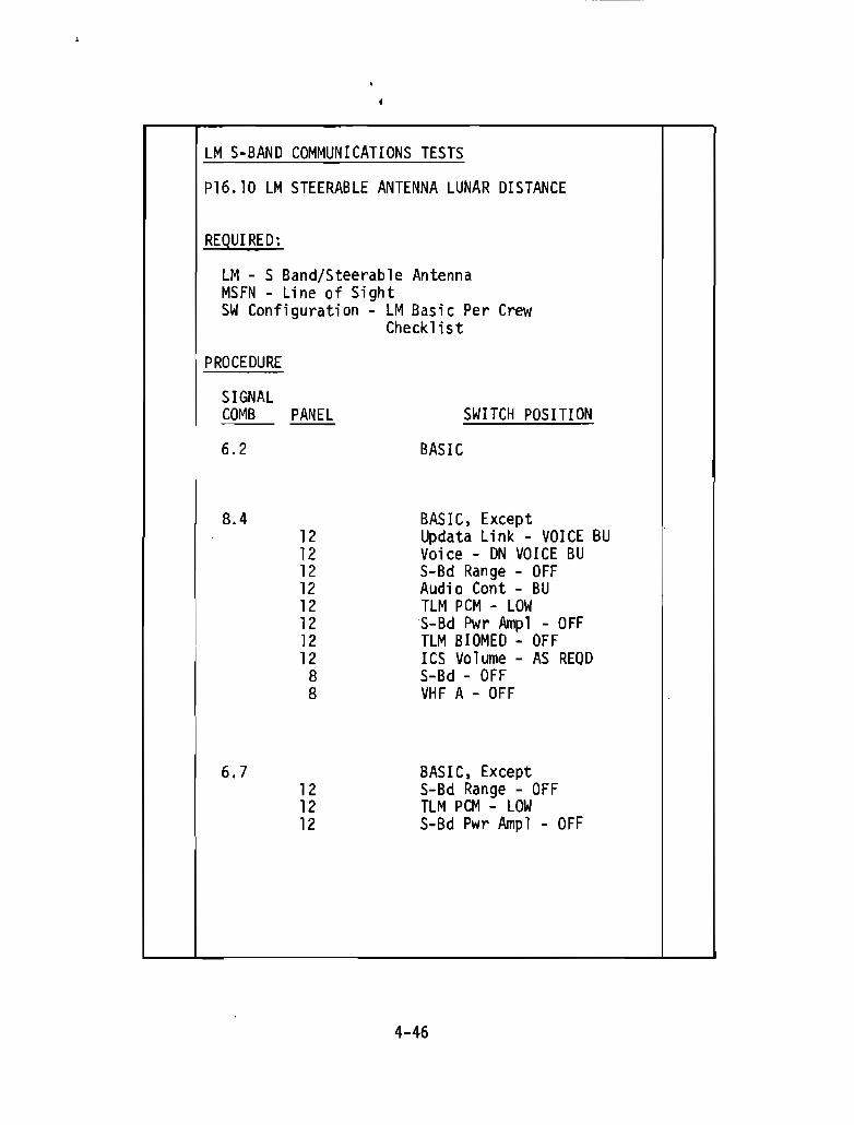
LM S-BAND COMMUNICATIONS TESTS
P16.10 LM STEERABLE ANTENNA LUNAR DISTANCE
REQUIRED:
LM - S Band/Steerable AntennaMSFN - Line of SightSW Configuration - LM Basic Per Crew
Checklist
PROCEDURE
SIGNALCOMB PANEL SWITCH POSITION
6.2 BASIC
B.4 BASIC, Except12 Updata Link - VOICE BU12 Voice - ON VOICE BU12 S-Bd Range - OFF12 Audio Cont - BU12 TLM PCM - LOW12 S-Bd Pwr Amp1 - OFF12 TLM BIOMED - OFF12 ICS Volume - AS REOD8 S-Bd - OFF8 VHF A - OFF
6.7 BASIC, Except12 S-Bd Range - OFF12 TLM PCM - LOW12 S-Bd Pwr Ampl - OFF
4-46
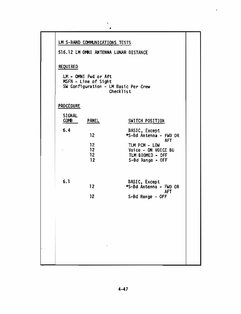
LM S-BAND COMMUNICATIONS TESTS
S16.12 LM DMNI ANTENNA LUNAR DISTANCE
REQUIRED
LM - OMNI Fwd or AftMSFN - Line.of SightSW Configuration - LM Basic Per Crew
Checklist
PROCEDURE
SIGNALCOMB PANEL SWITCH POSITION
6.4 BASIC, Except12 *S-Bd Antenna - FWD OR
AFT12 TLM PCM - LOW12 Voice - ON VOICE BU12 TLM BIOMED - OFF12 S-Bd Range - OFF
6.1 BASIC, Except12 *S-Bd Antenna - FWD OR
AFT12 S-Bd Range - OFF
4-47

PROCEDURE CON TO.
SIGNALCOMB PANEL SWITCH POSITION
6.15 BAsIC, Except12 *S-Bd Antenna - FWD OR
AFT12 Voice - OFF12 BIOMED - OFF
6.2 BASIC, Except12 *S-Bd Antenna - FWD OR
AFT
* Maneuver LM to Permit Optimum Communications WithEither the Forward or Rear Omni antenna.
4-48

----- -----------------r--""-lCOMMUNICATIONS RELAY MODES
816.17 LM/CSM/MSFN Voice/TM
REQUIRED
CSM S-Band/VHF1M ~-Band/VHF
MSFN - Line-of-SightSW. Configuration - C8M Basic Per Crew
Checklist1M Basic Per CrewChecklist
PROCEDURE
1.
LM .. VOICE VIA VHF.. C8M
CSMLM
FANEL
MSFN
SWITCH CONFIGURATION
BASICBASIC
L-_--L.- . .-l--..I
4-49
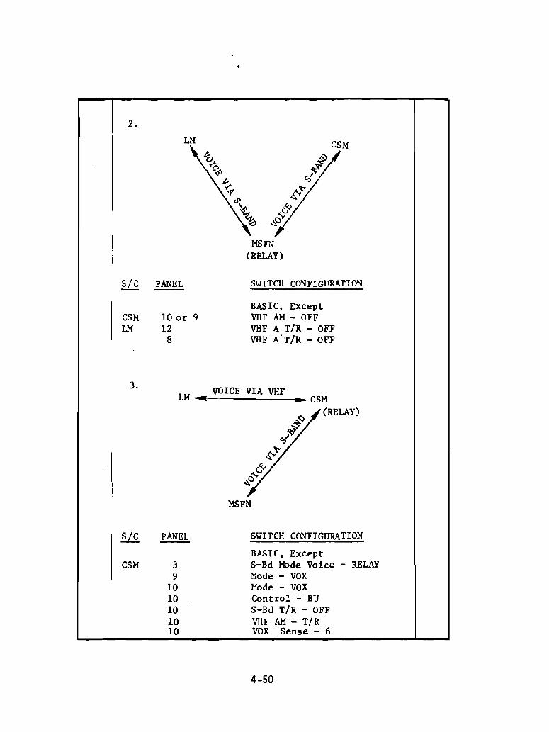
2.
LM
MSFN(RELAY)
SIC PANEL SWITCH CONFIGURATION
BASIC, ExceptCSM 10 or 9 VHF AM - OFFLM 12 VHF A r/R - OFF
8 VHF Ar/R - OFF
3.VOICE VIA VHF
LM .. .. CSM
J:(RELAY)
<!I.'"..
6-&
'"MSFN
Sic PANEL SWITCH CONFIGURATION
BASIC, ExceptCSM 3 S-Bd Mode Voice - RELAY
9 Mode - VOX10 Mode - VOX10 Control - BU10 S-Bd r/R - OFF10 VHF AM - r/R10 VOX Sense - 6
4-50
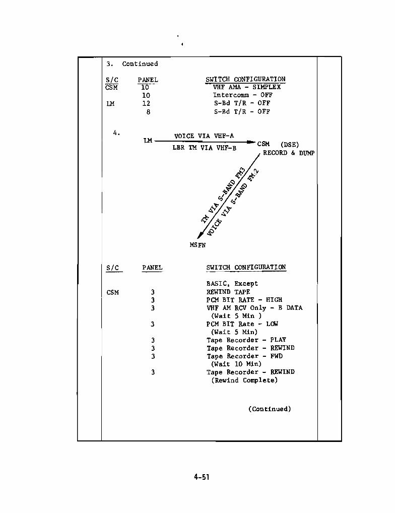
SWITCH CONFIGURATIONVHF AMA - SIMPLEXIntercomm - OFFS-Bd T/R - OFFS-Bd TIR - OFF
VOICE VIA VHF-A--::::::::=.:..:::...:::::.,.=----.. CSM (DSE)LBR TM VIA VHF-BRECORD & DUMP
3. Continued
sic PANELCSM 10
10LIl 12
8
4.LIl
MSFN
SiC PANEL
CSM 333
3
333
3
SWITCH CONFIGURATION
BASIC, ExceptREWIND TAPEPCM BIT RATE - HIGHVHF AM RCV Only - B DATA
(Wait 5 Min )PCM BIT Rate - LOW
(Wait 5 Min)Tape Recorder - PLAYTape Recorder - REWINDTape Recorder - FWD
(Wait 10 Min)Tape Recorder - REWIND
(Rewind Complete)
(Continued)
4-51

4. Continued
Sic PANEL SWITCH CONFIGURATION
CSM 3 Tape Recorder - LM PCM3 Tape Recorder - FWD
(Wait 10 Min)
LM 12 TLM PCM - LOW12 S-Bd T/R - OFF
8 S-Bd T/R - OFF
5.(RELAY)
VOICE VIA VHFLM .. ... CSM
'0~'i!>
~.,.
'"\,"MSFN
SiC PANEL SWITCH CONFIGURATION
BASIC, ExceptCSM 10 or 9 S-Bd T/R - OFF
3 VHF B- DUPLEX3 VHF A - OFF
LM 8 VHF B - ReV8 Mode - VOX8 les T/R - OFF
12 RELAY - ON12 Mode - VOX12 ICS T/R - OFF12 Audio Cant - BU12 VHF B RCVR - ON
4-52
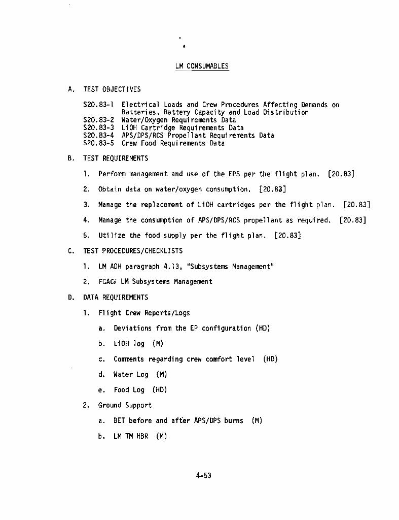
LM CONSUMABLES
A. TEST OBJECTIVES
520.83-1 Electrical Loads and Crew Procedures Affecting Demands onBatter; es ~ Battery Capacity and load Oi s tri but; on
520.83-2 Water/Oxygen Requi rerrents DataS20.83-3 LiOH Cartridge Requirements DataS20.83-4 APS/DPS/RCS Propellant Requirements Data520.83-5 Crew Food Requi rements Da ta
B. TEST REQUIREMENTS
1. Perform management and use of the EPS per the flight plan. [20.83]
2. Obtain data on water/oxygen consumption. [20.83]
3. Manage the replacement of LiOH cartridges per the flight plan. [20.83]
4. Manage the consumption of APS/DPS/RCS propellant as required. [20.83]
5. Utilize the food supply per the flight plan. [20.83]
C. TEST PROCEDURES/CHECKLISTS
1. LM AOH paragraph 4.13, "Subsystems Management"
2. FCAC, LM Subsystems Management
D. DATA REQUIREMENTS
1. Fl; ght Crew Reports/Logs
a. Deviations from the EP configuration (HD)
b. LiOH log (M)
c. Conments regarding crew comfort level (HD)
d. Water Log (M)
e. Food Log (HD)
2. Ground Support
a. BET before and after APS/OPS burns (M)
b. LM TM HBR (M)
4-53
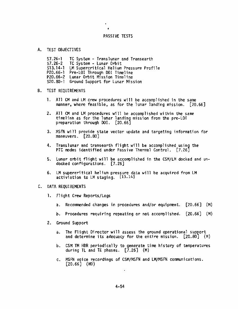
PASSIVE TESTS
A. TEST OBJECTIVES
57.26-157.26-2513.14-1P20.66-1P20.66-2520. BO-l
Te System - Translunar and TransearthTe System - Lunar OrbitLM Supercritical Helium Pressure ProfilePre-lOr Through 001 TimelineLunar Orbit Mission TimelineGround Support for Lunar Mission
4.
B. TEST REQUIREMENTS
1. All eM and LM crew procedures will be accomplished in the samemanner, where feasible, as for the lunar landing mission. [20.66]
2. All eM and lM procedures will be accomplished within the sametirneline as for the lunar landing mission from the pre-LOrpreparation through DOl. [20.66J
3. MSFN will provide state vector update and targeting information formaneuvers. [20.80]
Translunar and transearth flight will be accomplished using thePTC roodes identified under Passive Thermal Control. [7.26J
5. Lunar orbit flight will be accomplished in the CSM/lM docked and undocked configurations. [7.26]
6. lM supereritical helium pressure data will be acquired from lMactiviation to lM staging. [13.14]
C. DATA REQUIREMENTS
1. Fl i ght Crew Reports/Logs
a. Recommended changes in procedures and/or equipment. [20.66] (M)
b. Procedures requiring repeating or not accomplished. [20.66] (M)
2. Ground Support
a.
b.
The Flight Director will assess the ground operational supeortand determine its adequacy for the entire mission. [20.80J (M)
CSM TM HBR periodically to generate time history of temperaturesduring TL and TE phases. [7.26] (M)
c. MSFN voice r:ecordings of CSM/MSFN and lM/MSFN communications.[20.66] (HD)
4-54

•d. LM 1M HBR when LM is manned and activated while in lunarorbit of the front side of the IIDon. [7.26] (M)
e. LM 1M LBR [13.14] (M)
4-55

A. TEST OBJECTIVESS3.22-1 Deleted
TRANSEARTH INJECTION
4-56
SECTION 5 - CONSUMABLES ANALYSIS
CONSUMABLES OATA TO BE SUPPLIED
5-1