fuel and core design assessment - hse
TRANSCRIPT

Office for Nuclear RegulationAn agency of HSE
PROTECTIVE MARKING IF APPLICABLE
Generic Design Assessment – New Civil Reactor Build
Step 4 Fuel and Core Design Assessment of the Westinghouse AP1000® Reactor
Assessment Report: ONR-GDA-AR-11-005 Revision 0
11 November 2011

PROTECTIVE MARKING IF APPLICABLE
Report ONR-GDA-AR-11-005Office for Nuclear Regulation An agency of HSE
Revision 0
PROTECTIVE MARKING IF APPLICABLE
COPYRIGHT
© Crown copyright 2011 First published December 2011 You may reuse this information (excluding logos) free of charge in any format or medium, under the terms of the Open Government Licence. To view the licence visit www.nationalarchives.gov.uk/doc/open-government-licence/, write to the Information Policy Team, The National Archives, Kew, London TW9 4DU, or email [email protected].
Some images and illustrations may not be owned by the Crown so cannot be reproduced without permission of the copyright owner. Enquiries should be sent to [email protected].
Unless otherwise stated, all corporate names, logos, and Registered® and Trademark™ products mentioned in this Web site belong to one or more of the respective Companies or their respective licensors. They may not be used or reproduced in any manner without the prior written agreement of the owner(s).
For published documents, the electronic copy on the ONR website remains the most current publically available version and copying or printing renders this document uncontrolled.

PROTECTIVE MARKING IF APPLICABLE
Report ONR-GDA-AR-11-005Office for Nuclear Regulation An agency of HSE
Revision 0
Page (i)
PREFACE
The Office for Nuclear Regulation (ONR) was created on 1st April 2011 as an Agency of the Health and Safety Executive (HSE). It was formed from HSE's Nuclear Directorate (ND) and has the same role. Any references in this document to the Nuclear Directorate (ND) or the Nuclear Installations Inspectorate (NII) should be taken as references to ONR.
The assessments supporting this report, undertaken as part of our Generic Design Assessment (GDA) process, and the submissions made by Westinghouse relating to the AP1000® reactor design, were established prior to the events at Fukushima, Japan. Therefore, this report makes no reference to Fukushima in any of its findings or conclusions. However, ONR has raised a GDA Issue which requires Westinghouse to demonstrate how they will be taking account of the lessons learnt from the events at Fukushima, including those lessons and recommendations that are identified in the ONR Chief Inspector’s interim and final reports. The details of this GDA Issue can be found on the Joint Regulators’ new build website www.hse.gov.uk/newreactors and in ONR’s Step 4 Cross-cutting Topics Assessment of the AP1000® reactor.
PROTECTIVE MARKING IF APPLICABLE
Report ONR-GDA-AR-11-005Office for Nuclear Regulation An agency of HSE
Revision 0
Page (ii)
EXECUTIVE SUMMARY
This report presents the findings of the Fuel and Core Design assessment of the AP1000 reactor undertaken as part of Step 4 of the Health and Safety Executive’s Generic Design Assessment. The assessment has been carried out on the Pre-construction Safety Report and supporting documentation submitted by Westinghouse during Generic Design Assessment Step 4.
This assessment has followed a step-wise-approach in a claims-argument-evidence hierarchy. In Generic Design Assessment Step 2 the claims made by Westinghouse were examined, in Generic Design Assessment Step 3 the arguments that underpin those claims were examined.
The scope of the Generic Design Assessment Step 4 was to review the safety aspects of the AP1000 reactor in greater detail, by examining the evidence, supporting arguments and claims made in the safety documentation, building on the assessments already carried out for Generic Design Assessment Steps 2 and 3, and to make a judgement on the adequacy of the Fuel and Core Design information contained within the Pre-construction Safety Report and supporting documentation, including the responses to queries.
It is seldom possible, or necessary, to assess a safety case in its entirety, therefore sampling is used to limit the areas scrutinised, and to improve the overall efficiency of the assessment process. Sampling is done in a focused, targeted and structured manner with a view to revealing any topic-specific, or generic, weaknesses in the safety case. To identify the sampling needed for the Fuel and Core Design an assessment plan for Generic Design Assessment Step 4 was set-out in advance. My assessment has focussed on:
Aspects of the fuel and core design which could conceivably cause the Critical Heat Flux to be exceeded and therefore impair cooling of the fuel.
Design Criteria which during Step 3 appeared not to meet UK safety objectives or modern standards.
Areas of the design that introduce novel features.
Parts of the topic area not considered in detail in Generic Design Assessment Step 3 including the validation of key computer models.
The result of my assessment is given in this report. From my assessment I have determined that:
The fuel design for AP1000 is a development of existing Westinghouse products and appears to have benefited from a successful programme to improve the performance and reliability of the fuel.
The approach to qualifying new aspects of the design appears to be systematic and reasonable although the detail provided in the safety submission was initially insufficient for UK licensing and more information was required as part of the Generic Design Assessment review.
Westinghouse has enhanced core diagnostic capabilities by addition of in-core instrumentation. However, some aspects of its use require further justification.
Westinghouse is continuing to make progress in their analysis methods and in minimising the potential for degradation of the fuel condition during irradiation.
As a result of the Generic Design Assessment process, measures have been taken to improve the protection of the fuel cladding against cracking during faults. Moreover, additional safety constraints and improved analysis techniques have been developed.

PROTECTIVE MARKING IF APPLICABLE
Report ONR-GDA-AR-11-005Office for Nuclear Regulation An agency of HSE
Revision 0
Page (iii)
More detailed analysis of fuel damage has shown that even with the temperatures experienced in the worst credible loss-of-coolant accident, a coolable geometry is likely.
An acceptable case has been made for loading Westinghouse fuel into the AP1000 reactor. However, Nuclear Directorate will need to assess the additional information that becomes available as the Generic Design Assessment Design Reference is supplemented with additional details on a site by site basis.
In some areas there has been a lack of detailed information which has limited the extent of my assessment. As a result, Nuclear Directorate will need additional information to underpin my conclusion and these requirements are identified as Assessment Findings to be carried forward as normal regulatory business. These are listed in Annex 1.
I note that a number of core loading pattern strategies have been considered, but a selection will need to be made by the licensee in due course and this will need to be analysed and justified. In particular, this will include showing consistency with the generic limits that have been substantiated.
Results of ongoing fuel examination and testing are expected to confirm my conclusions in a number of areas. The data anticipated include further detail on assembly distortion, crud and the dry storage of spent fuel. In particular:
Westinghouse has systematic methods of addressing assembly distortion which are commendable and in consultation with plant operators, will need to develop a planned programme of measurement on assemblies of the AP1000 design.
Details of surveillance for fuel crud have yet to be finalised and an acceptance criterion requires more substantial justification.
More information is required on the performance of the cladding of spent fuel in dry storage to strengthen the evidence currently available.
Some of the observations identified within this report are of particular significance and will require resolution before HSE would agree to the commencement of nuclear safety-related construction of an AP1000 reactor in the UK. These are identified in this report as Generic Design Assessment Issues and are listed in Annex 2. In summary these relate to requirements to:
Take more explicit account of approximations in the modelling of fuel pin performance, with particular reference to the modelling of fuel pellet temperatures.
Address the issue of forces on reactor internals in the event of a large depressurisation fault.
Systematically consider the effect of any potential malfunction of the BEACON™ software system.
Reconcile the generic core design data with assumptions made in recent fault studies to ensure that they are realised in practice.

PROTECTIVE MARKING IF APPLICABLE
Report ONR-GDA-AR-11-005Office for Nuclear Regulation An agency of HSE
Revision 0
Page (iv)
There will be a need to update the supporting documentation to reflect the changes made within Generic Design Assessment and rectify some shortfalls in the level of detail required, but overall, based on the sample undertaken in accordance with Nuclear Directorate procedures, I am broadly satisfied that the claims, arguments and evidence laid down within the Pre-construction Safety Report and supporting documentation submitted as part of the Generic Design Assessment process present an adequate safety case for the generic AP1000 reactor design. The AP1000 reactor is therefore suitable for construction in the UK, subject to satisfactory progression and resolution of Generic Design Assessment Issues to be addressed during the forward programme for this reactor and assessment of additional information that becomes available as the Generic Design Assessment Design Reference is supplemented with additional details on a site-by-site basis.

PROTECTIVE MARKING IF APPLICABLE
Report ONR-GDA-AR-11-005Office for Nuclear Regulation An agency of HSE
Revision 0
Page (v)
LIST OF ABBREVIATIONS
ALARP As Low As Reasonably Practicable
ASME American Society of Mechanical Engineers
BMS (Nuclear Directorate) Business Management System
CHF Critical Heat Flux (for departure from nucleate boiling)
DNB Departure from Nucleate Boiling
DNBR Departure from Nucleate Boiling Ratio
DFBN Debris Filter Bottom Nozzle
EPRI Electrical Power Research Institute
GDA Generic Design Assessment
GRCA Gray Rod Cluster Assemblies
HSE The Health and Safety Executive
IAEA International Atomic Energy Agency
IFBA Integral Fuel Burnable Absorber
LBLOCA Large-break Loos-of-coolant Accident
LOCA Loss-of-coolant Accident
ND The (HSE) Nuclear Directorate
ONR Office for Nuclear Regulation
PCER Pre-construction Environment Report
PCI Pellet-clad Interaction (including both stress and corrosive effects).
PCMI Pellet-clad mechanical Interaction
PCSR Pre-construction Safety Report
PSI Paul Scherrer Institute
RAPFE Radial-averaged Peak Fuel Enthalpy
RCCA Reactivity Control Cluster Assembly (control rod assembly)
RCSL Reactor Control Surveillance and Limitation
RI Regulatory Issue
RIA Regulatory Issue Action
RO Regulatory Observation
ROA Regulatory Observation Action
SAP Safety Assessment Principle
SSC System, Structure and Component
STUK Finnish Radiation and Nuclear Safety Authority
TAG (Nuclear Directorate) Technical Assessment Guide
TQ Technical Query
TPA Thimble Plug Assemblies

PROTECTIVE MARKING IF APPLICABLE
Report ONR-GDA-AR-11-005Office for Nuclear Regulation An agency of HSE
Revision 0
Page (vi)
LIST OF ABBREVIATIONS
US NRC United States Nuclear Regulatory Commission
WABA Wet Annular Burnable Absorbers
WANO World Association of Nuclear Operators
WENRA The Western European Nuclear Regulators’ Association

PROTECTIVE MARKING IF APPLICABLE
Report ONR-GDA-AR-11-005Office for Nuclear Regulation An agency of HSE
Revision 0
Page (vii)
TABLE OF CONTENTS
1 INTRODUCTION...................................................................................................................... 1
2 NUCLEAR DIRECTORATE’S ASSESSMENT STRATEGY FOR FUEL AND CORE DESIGN2 2.1 Assessment Plan ............................................................................................................ 2 2.2 Standards and Criteria .................................................................................................... 2 2.3 Assessment Scope ......................................................................................................... 3
2.3.1 Findings from GDA Step 3............................................................................................. 3 2.3.2 Additional Areas for Step 4 Fuel and Core Design Assessment ................................... 3 2.3.3 Use of Technical Support Contractors........................................................................... 3 2.3.4 Cross-cutting Topics and Integration with Other Assessment Topics........................... 4 2.3.5 Out of Scope Items ........................................................................................................ 5
3 WESTINGHOUSE’S SAFETY CASE....................................................................................... 6 3.1 Control of Core Reactivity ............................................................................................... 7 3.2 Nuclear Design ............................................................................................................... 8 3.3 Thermal Hydraulic Design............................................................................................... 9 3.4 Design Requirements ..................................................................................................... 9 3.5 Structure of the Supporting Documentation.................................................................... 9
4 GDA STEP 4 NUCLEAR DIRECTORATE ASSESSMENT FOR FUEL AND CORE DESIGN 11 4.1 Core Power Distribution ................................................................................................ 11
4.1.1 Westinghouse Case..................................................................................................... 11 4.1.2 Assessment ................................................................................................................. 12 4.1.3 First Core design ......................................................................................................... 13 4.1.4 Equilibrium Core Designs ............................................................................................ 14 4.1.5 Findings ....................................................................................................................... 14
4.2 Assembly Edge Effects ................................................................................................. 14 4.2.1 Westinghouse Case..................................................................................................... 15 4.2.2 Assessment ................................................................................................................. 15 4.2.3 Finding ......................................................................................................................... 16
4.3 Core Stability................................................................................................................. 17 4.3.1 Westinghouse Case..................................................................................................... 17 4.3.2 Assessment ................................................................................................................. 17 4.3.3 Finding ......................................................................................................................... 17
4.4 Fuel and Core Neutronic Performance in Normal Operation and Faults ...................... 18 4.4.1 Westinghouse Case..................................................................................................... 18 4.4.2 Assessment ................................................................................................................. 18 4.4.3 Shutdown Margin......................................................................................................... 18 4.4.4 Moderator Temperature Response ............................................................................. 19 4.4.5 Findings ....................................................................................................................... 19
4.5 The Beacon™ Core Monitoring Code........................................................................... 19 4.5.1 Westinghouse Case..................................................................................................... 20 4.5.2 Assessment ................................................................................................................. 21

PROTECTIVE MARKING IF APPLICABLE
Report ONR-GDA-AR-11-005Office for Nuclear Regulation An agency of HSE
Revision 0
Page (viii)
4.6 Qualification of Westinghouse Physics Codes.............................................................. 22 4.6.1 Westinghouse Case..................................................................................................... 22 4.6.2 Assessment ................................................................................................................. 22 4.6.3 Physics Testing............................................................................................................ 23
4.7 Core Misloading Faults ................................................................................................. 23 4.7.1 Westinghouse Case..................................................................................................... 24 4.7.2 Assessment ................................................................................................................. 24 4.7.3 Finding ......................................................................................................................... 25
4.8 Fuel Pin Performance Modelling................................................................................... 25 4.8.1 Westinghouse Case..................................................................................................... 26 4.8.2 Assessment ................................................................................................................. 26
4.9 Fuel Clad Corrosion...................................................................................................... 27 4.9.1 Westinghouse Case..................................................................................................... 27 4.9.2 Assessment ................................................................................................................. 28
4.10 Crud Mitigation.............................................................................................................. 28 4.10.1 Westinghouse Case..................................................................................................... 28 4.10.2 Assessment ................................................................................................................. 29 4.10.3 Findings ....................................................................................................................... 30
4.11 Fuel Clad Stress ........................................................................................................... 30 4.11.1 Westinghouse Case..................................................................................................... 30 4.11.2 Assessment ................................................................................................................. 31 4.11.3 Stress-corrosion Cracking ........................................................................................... 31 4.11.4 Cladding Fatigue.......................................................................................................... 32
4.12 High Burnup Issues....................................................................................................... 32 4.12.1 Westinghouse Case..................................................................................................... 33 4.12.2 Assessment ................................................................................................................. 33
4.13 Critical Heat Flux........................................................................................................... 33 4.13.1 Westinghouse Case..................................................................................................... 34 4.13.2 Assessment ................................................................................................................. 34 4.13.3 Qualification of VIPRE ................................................................................................. 35 4.13.4 Finding ......................................................................................................................... 36
4.14 Fuel Performance in Reactivity Faults .......................................................................... 36 4.14.1 Westinghouse Case..................................................................................................... 36 4.14.2 Assessment ................................................................................................................. 36
4.15 Fuel Performance in Loss of Coolant Accidents ........................................................... 37 4.16 Fuel Assembly Component Design............................................................................... 38
4.16.1 Westinghouse Case..................................................................................................... 38 4.16.2 Spacer Grids................................................................................................................ 38 4.16.3 Top Nozzle................................................................................................................... 39 4.16.4 Bottom Nozzle ............................................................................................................. 39 4.16.5 Assessment ................................................................................................................. 39 4.16.6 Spacer Grids................................................................................................................ 40 4.16.7 Top Nozzle................................................................................................................... 41 4.16.8 Bottom Nozzle ............................................................................................................. 41 4.16.9 Guide tubes ................................................................................................................. 41

PROTECTIVE MARKING IF APPLICABLE
Office for Nuclear Regulation An agency of HSE
Report ONR-GDA-AR-11-005Revision 0
Page (ix)
4.17 Non-fuel Core Components .......................................................................................... 42 4.17.1 Westinghouse Case..................................................................................................... 42 4.17.2 Rod Cluster Control Assemblies.................................................................................. 43 4.17.3 Wet Annular Burnable Absorber Rod (WABA) ............................................................ 43 4.17.4 Neutron Sources.......................................................................................................... 44 4.17.5 Assessment ................................................................................................................. 44 4.17.6 Control Rods................................................................................................................ 44 4.17.7 Wet Annular Burnable Absorber.................................................................................. 45 4.17.8 Primary Source Rods................................................................................................... 45 4.17.9 Secondary Source Rods.............................................................................................. 46 4.17.10 Thimble Plug Assembly (TPA)..................................................................................... 46 4.17.11 Finding ......................................................................................................................... 46
4.18 Long-term Storage of Spent Fuel in Interim Storage Facilities ..................................... 46 4.18.1 Westinghouse Case..................................................................................................... 47 4.18.2 Assessment ................................................................................................................. 47 4.18.3 Cladding Creep............................................................................................................ 47 4.18.4 Corrosion ..................................................................................................................... 48 4.18.5 Hydride Embrittlement ................................................................................................. 48 4.18.6 Stress-corrosion Cracking ........................................................................................... 49 4.18.7 Finding ......................................................................................................................... 49
4.19 Overseas Regulatory Interface ..................................................................................... 49 4.20 Interface with Other Regulators .................................................................................... 49 4.21 Other Health and Safety Legislation ............................................................................. 50
5 CONCLUSIONS..................................................................................................................... 51 5.1 Key Findings from the Step 4 Assessment ................................................................... 51
5.1.1 Assessment Findings................................................................................................... 52 5.1.2 GDA Issues.................................................................................................................. 52
6 REFERENCES....................................................................................................................... 53
Tables
Table 1: Areas for Further Assessment During Step 4.
Table 2: Relevant Safety Assessment Principles for Fuel and Core Design considered during Step 4.
Annexes
Annex 1: Assessment Findings to be Addressed During the Forward Programme as Normal Regulatory Business – Fuel and Core Design – AP1000
Annex 2: GDA Issues - Fuel and Core Design – AP1000

PROTECTIVE MARKING IF APPLICABLE
Report ONR-GDA-AR-11-005Office for Nuclear Regulation An agency of HSE
Revision 0
Page 1
1 INTRODUCTION
1 This report presents the findings of the Step 4 Fuel and Core Design assessment of the AP1000 reactor Pre-construction Safety Report (PCSR) (Ref. 13) and supporting documentation provided by Westinghouse under the Health and Safety Executive's (HSE) Generic Design Assessment (GDA) process. Assessment was undertaken of the Pre-construction Safety Report (PCSR) and the supporting evidentiary information derived from the Master Submission List (Ref. 15). The approach taken was to assess the principal submission, i.e. the PCSR, and then undertake assessment of the relevant documentation sourced from the Master Submission List on a sampling basis in accordance with the requirements of the Nuclear Directorate (ND) Business Management System (BMS) procedure AST/001 (Ref. 2). The Safety Assessment Principles (SAP) (Ref. 4) have been used as the basis for this assessment. Ultimately, the goal of assessment is to reach an independent and informed judgment on the adequacy of a nuclear safety case.
2 During the assessment a number of Technical Queries (TQ), and Regulatory Observations (RO) were issued and the responses made by Westinghouse assessed.
3 Details of the assessment strategy are given in Section 2. A number of items have been agreed with Westinghouse as being outside the scope of the GDA process and hence have not been included in this assessment. See Section 2.3 for the particular case of Fuel and Core Design.
4 A short overview of the safety case presented in the Fuel and Core Design topic area is given in Section 3 and my assessment of the case is detailed in Section 4.

PROTECTIVE MARKING IF APPLICABLE
Report ONR-GDA-AR-11-005Office for Nuclear Regulation An agency of HSE
Revision 0
Page 2
2 NUCLEAR DIRECTORATE’S ASSESSMENT STRATEGY FOR FUEL AND CORE DESIGN
5 The intended assessment strategy for GDA Step 4 for the Fuel and Core Design topic area was set out in an assessment plan that identified the intended scope of the assessment and the standards and criteria that would be applied. This is summarised below:
2.1 Assessment Plan
6 The plan for assessment of fuel and core in GDA Step 4 is set out in Ref. 1. Particular focus was placed on the evidence required to support the values for safety limits presented as design criteria in the safety case. The assessment focused on the following topics:
Because of its high safety significance, aspects of the fuel and core design which may influence the critical heat flux and therefore impair cooling of the fuel.
Design criteria which appear not to meet UK safety objectives or modern standards in the case presented for GDA Step 4.
Parts of the topic area not considered in detail in Step 3 including the validation of key computer models.
7 The specific Fuel and Core Design assessment aims for GDA Step 4 are detailed in Table 1. The major items in Table 1 form the basis of the assessment detailed in Section 4 of this report together with the findings from the assessment carried out in GDA Step 3.
2.2 Standards and Criteria
8 The standards and criteria that are used to judge the AP1000 are the 2006 HSE SAPs for Nuclear Facilities (Ref. 4). In particular, the following are considered:
key principles EKP.1 to EKP.3;
reliability claims ERL.1 to ERL.2;
commissioning ECM.1;
maintenance, inspection and testing EMT.1;
ageing and degradation EAD.1 to EAD.2;
reactor core ERC.1 to ERC.4; and
fault analysis FA.4, 9, 17 to 21.
9 More details of these criteria are found in Table 2.
10 Westinghouse has have assessed the safety case against their own design requirements. The American Society of Mechanical Engineering (ASME) publishes design and construction rules, which constitute a set of design and inspection criteria for the fuel. Westinghouse has adopted these. This follows standard practice in the industry.
11 Detailed design rules are discussed in Section 3 below.

PROTECTIVE MARKING IF APPLICABLE
Report ONR-GDA-AR-11-005Office for Nuclear Regulation An agency of HSE
Revision 0
Page 3
2.3 Assessment Scope
12 For the purposes of GDA, the assessment has concentrated on examining the core designed for an 18-month reload cycle utilising enriched uranium-dioxide pellets. This is because I understand that this design is most likely to be loaded initially. In practice, actual core designs vary in detail and require some assessment prior to each core loading.
2.3.1 Findings from GDA Step 3
13 My GDA Step 3 report identified a number of specific issues which need addressing by Westinghouse in sufficient time to be assessed in Step 4:
proposals to demonstrate no clad failures due to thermal stress in postulated frequent faults;
justification of design criteria and interface parameters including justification of the Radial-averaged Peak Fuel Enthalpy criterion to reflect good practice;
the case for operation with surface crud on the fuel;
implications of crud for Critical Heat Flux (CHF) and the proposed measures for surveillance;
assessment of the effect of changes to fuel design and cladding material on preservation of coolable fuel geometry in large Loss of Coolant Accidents (LOCA) faults;
CHF performance of the edge of the spacer;
the design substantiation of novel components; and
longer-term safety of the fuel following discharge from the reactor building to a long-term storage facility.
14 In each of these areas, Westinghouse has made substantial progress within GDA Step 4 and the detailed findings of my assessment are discussed in Section 4 of this report.
2.3.2 Additional Areas for Step 4 Fuel and Core Design Assessment
15 I identified areas that were not assessed in GDA Step 3 and these are:
performance and integrity of non-fuel core components;
arrangements for surveillance and monitoring of core power distribution and physics parameters;
the appropriateness and validity of the computer codes used in accordance with SAPs FA.17 to FA.21; and
independent confirmatory analysis undertaken by Technical Support Contractors.
2.3.3 Use of Technical Support Contractors
16 Technical support contractors have been used in four areas:
the development of an independent nuclear physics model of the AP1000 reactor core and the determination of reactor core kinetics parameters;
PROTECTIVE MARKING IF APPLICABLE
Report ONR-GDA-AR-11-005Office for Nuclear Regulation An agency of HSE
Revision 0
Page 4
the assessment of the fuel behaviour in the large loss-of-coolant accident;
the assessment of crud mitigation; and
the review of the requirements for long-term storage of spent fuel.
17 The contractor review of spent fuel was managed in the Waste and Decommissioning area and is reported in (Ref. 62). I used that report as a starting point for my assessment of the likely degradation of the fuel during storage. See Section 4.18. The assessment of waste storage generally is reported in Ref. 63.
18 Similarly, the analysis of primary chemistry to assess the likelihood of crud deposits has been managed by my chemistry colleagues and is reported in Ref. 64. This reference provides some independent confirmation of the claims made. The chemistry assessment for GDA is reported in Ref. 65.
19 The remainder of these tasks were confirmatory calculations carried out using independent analysis codes.
20 The reactor core model developed by my contractor is reported in Ref. 66. The model was principally developed for use in fault studies and was intentionally not as spatially detailed as the Westinghouse model, but results were consistent with those of Westinghouse.
21 The analysis of the effect of the large loss-of-coolant accident was prompted by the temperatures predicted for some fuel, which indicated that a significant number of fuel pins are likely to burst following depressurisation and emptying of the reactor vessel and coolant circuit. Confirmatory analysis with advanced analysis methods was performed using an independent fuel pin model (Ref. 67). The results confirmed the argument that the postulated fuel cladding bursts will not lead to a general loss of fuel rod structural integrity and any resulting restriction to coolant flow will be tolerable. More details are found in Section 4.15.
2.3.4 Cross-cutting Topics and Integration with Other Assessment Topics
22 The following formal Cross-cutting Topics have been considered within this report:
Limits & Conditions; and
Spent Fuel Pond.
23 When considering limits to the fuel operation, the interaction with fault studies has inevitably been routine and the two assessment areas have been very closely integrated, with contact on a daily basis. My particular concern has been to ensure that the assumptions on fuel performance made in fault studies are realised in practice, both in the physical design of the fuel and in the design of core loading patterns.
24 The storage of spent fuel has also required collaboration. My colleague in waste disposal assessed the fuel storage and disposal facilities and strategy, and I assessed the fuel rod performance limits that need to be respected. For the details of the assessment of waste storage, please see Ref. 63.
25 In addition, fuel crud is principally a chemistry issue and I have collaborated with my chemistry colleagues in this area. They have carried out a thorough assessment of a technically challenging area. My concern has been to ensure that there are inspection standards and mitigation measures necessary to ensure that crud will not adversely affect the fuel performance. Assessment of wider issues related to crud is found in Ref. 65.

PROTECTIVE MARKING IF APPLICABLE
Report ONR-GDA-AR-11-005Office for Nuclear Regulation An agency of HSE
Revision 0
Page 5
2.3.5 Out of Scope Items
26 The following items relevant to fuel and core have been agreed with the RP as being outside the scope of GDA:
27 The use of mixed oxides of uranium and plutonium (MOX) has been considered outside the scope of GDA and would require significant assessment effort. It is anticipated that a particular safety case will be developed for each proposed core loading pattern and that issues such as the use of MOX will be considered as a modification to the generic safety case in accordance with the arrangements defined under the site licence.
Technical Specifications for the reactor are presented in the EDCD but these have not been assessed in GDA. It is for a future operator to produce definitive Technical Specifications and Operating Procedures.
The design of storage facilities for spent fuel, although the constraints on fuel required to be respected by such a design is within the scope.

PROTECTIVE MARKING IF APPLICABLE
Report ONR-GDA-AR-11-005Office for Nuclear Regulation An agency of HSE
Revision 0
Page 6
3 WESTINGHOUSE’S SAFETY CASE
28 The safety case is summarised in Chapter 22 of the Pre-construction Safety Report (Ref. 14), with further detail presented in the European Design Control Document (Ref. 18).
29 The reactor contains a matrix of fuel rods supported in mechanically identical fuel assemblies along with control and structural elements. The assemblies are loaded within a fabricated steel core barrel. This directs the flow of the coolant past the fuel rods.
30 An AP1000 fuel assembly consists of 264 fuel rods in a 17x17 square array. The centre position in the fuel assembly has a guide tube that is reserved for in-core instrumentation. A further 24 positions in the fuel assembly have guide thimbles for control rods. The guide thimbles are joined to the top and bottom nozzles of the fuel assembly and provide the supporting structure for the fuel spacer grids.
31 The fuel spacer grids consist of an egg-crate arrangement of interlocked straps that maintain lateral spacing between the fuel rods. The grid straps have spring fingers and dimples that grip and support the fuel rods. The intermediate mixing vane grids also have coolant mixing vanes. The top and bottom grids do not contain mixing vanes.
32 The AP1000 fuel assemblies are similar to the 17x17 Robust and 17x17 XL Robust fuel assemblies. The design benefits from their substantial operating experience.
33 The bottom nozzle has a debris filter that minimizes the potential for fuel damage due to debris in the reactor coolant. The AP1000 fuel assembly design also includes a protective grid for enhanced debris resistance.
34 The fuel rods consist of enriched uranium, in the form of cylindrical pellets of uranium dioxide, contained in ZIRLO™ (Ref. 8) tubing. The tubing is plugged and seal welded at the ends to encapsulate the fuel.
35 The fuel rods in the AP1000 fuel assemblies contain additional gas space below the fuel pellets, compared to other previous fuel assembly designs. This allows for increased fission gas production due to high fuel burnups.
36 Depending on the position of the assembly in the core, the guide thimbles can be loaded with:
Rod Cluster Control Assemblies (RCCA);
Gray Rod Cluster Assemblies (GRCA);
neutron source assemblies;
non-integral discrete burnable absorber (BA) assemblies; or
thimble plugs.
37 With the exception of the thimble plugs, which are used to limit the fraction of the flow bypassing the fuel, these components are used to control core reactivity and power distribution.
38 The bottom nozzle is a box-like structure that serves as the lower structural element of the fuel assembly and directs the coolant flow into the assembly. The size of flow passages through the bottom nozzle limits the size of debris that can enter the fuel assembly.
39 The top nozzle assembly serves as the upper structural element of the fuel assembly and provides a guide for the rod cluster control assembly or other components.

PROTECTIVE MARKING IF APPLICABLE
Report ONR-GDA-AR-11-005Office for Nuclear Regulation An agency of HSE
Revision 0
Page 7
40 With the exception of zirconium alloy tubes and grids, structural members are constructed of Type 304 stainless steel. The springs exposed to the reactor coolant are nickel-chromium-iron Alloy 718. These materials provide suitable resistance to stress-corrosion cracking in the reactor environment.
41 The analysis confirming compliance with Design Criteria is set out in Ref. 19.
3.1 Control of Core Reactivity
42 The principle short term control of reactivity is carried out by moving rod cluster control assemblies in and out of the core. The Rod Cluster Control Assemblies (RCCA) are divided into two categories, control and shutdown. The control groups compensate for reactivity changes due to variations in operating conditions of the reactor, that is, power and temperature variations and to some extent, fuel depletion of fissile material.
43 Two nuclear design criteria have been employed for selection of the control group.
First, the total reactivity worth must be adequate to meet the nuclear requirements of the reactor.
Second, in view of the fact that these rods may be partially inserted at power operation, the total power peaking factor should be low enough to confirm that the power capability is met.
44 The control and shutdown groups provide adequate shutdown margin. The RCCAs have neutron absorber material over the active length of the control rods.
45 The rod cluster control assemblies consist of 24 absorber rods fastened at the top end to a common hub assembly. Each absorber rod consists of an alloy of silver-indium-cadmium, which is clad in stainless steel. The rod cluster control assemblies are used to control relatively rapid changes in reactivity and to control the axial power distribution.
46 The gray rod cluster assemblies consist of 24 rodlets fastened at the top end to a common hub. Geometrically, the gray rod cluster assembly is the same as a normal rod cluster control assembly except that 12 of the 24 rodlets are fabricated of stainless steel, while the remaining 12 are silver-indium-cadmium (of a reduced diameter as compared to the RCCA absorber) with stainless steel clad.
47 The gray rod cluster assemblies are used to compensate for changes in core reactivity with power level as the power demanded is varied. This minimises the need for changes to the concentration of soluble boron.
48 Soluble boron in the moderator/coolant serves as a neutron absorber. The concentration of boron is varied to control reactivity changes that occur relatively slowly, including the effects of fuel burnup. Fixed burnable absorbers are also employed for reactivity control. These reduce reactivity in the early part of a cycle of irradiation before becoming depleted. They limit the amount of soluble boron required and thereby maintain the desired negative feedback in response to changes in coolant density.
49 The burnable absorber rods consist of borosilicate glass tubes contained within Type 304 stainless steel tubular cladding, which is plugged and seal welded at the ends to encapsulate the glass.
50 The Wet Annular Burnable Absorber rods (WABA) consist of pellets of alumina-boron carbide material contained within zirconium alloy tubes. These zirconium alloy tubes, which form the outer clad for the burnable absorber rod, are plugged, pressurized with helium, and seal-welded at each end to encapsulate the stack of absorber material.
PROTECTIVE MARKING IF APPLICABLE
Report ONR-GDA-AR-11-005Office for Nuclear Regulation An agency of HSE
Revision 0
Page 8
51 The performance of the core is monitored by fixed neutron detectors outside the core, fixed neutron detectors within the core, and thermocouples at the outlet of selected fuel assemblies. The ex-core nuclear instrumentation provides input to automatic control functions.
52 For the first core, a neutron source is placed in the reactor to provide a positive neutron count of at least two counts per second on the source range detectors attributable to core neutrons. The source assembly also permits detection of changes in the core multiplication factor during core loading, refuelling, and approach to criticality. In core reloads, the primary sources are replaced by secondary source assemblies, which gain their activity by irradiation in the previous loading cycle.
53 The primary and secondary source rods both use the same cladding material as the absorber rods. The secondary source rods contain antimony-beryllium pellets. The primary source rods contain capsules of californium source material and alumina spacers to position the source material within the cladding.
54 Dynamic control of power distribution is achieved predominantly by automatic control using a combination of banks of control rods. Two functions are achieved: control of coolant temperature and control of axial power shape. These control functions are based on signals from neutron flux detectors located outside of the reactor core (ex-core).
55 The reactor power control system enables the plant to respond to the following load change transients without a reactor trip or steam dump actuation by compensating for changes in coolant temperature with steam demand.
56 The axial offset control subsystem controls the core axial power difference between the top and bottom halves of the core to a value that is within the desired control range for load follow and grid frequency change transients. This is accomplished by using control rod banks separate from those used for the reactor power control.
57 The combination of these systems is likely to reduce the requirements on the operator to act to control axial power shapes and potentially reduces the likelihood of the plant operating with reduced margins to safety limits.
58 Incore power distribution is monitored by a series of vanadium wire neutron detectors placed within instrumentation tubes in fuel assemblies. These instruments are too slow to be a candidate for automatic protection (Ref. 49), but provide detailed data for diagnostic purposes and combined with the BEACON™ physics code, can detect even relatively small changes in local reactivity.
3.2 Nuclear Design
59 The nuclear design analyses establish the core locations for control rods and burnable absorbers. The design requirements are set down in a well established procedure approved within the US, based on the results of fault studies.
60 Fault analyses of the core operation determines the values of limiting design criteria, such as fuel enrichments and boron concentration in the coolant.
61 The nuclear design establishes that the reactor core and the reactor control system satisfy the design criteria, even under limiting conditions of operation.
62 In addition the operability of the core is confirmed. For example, axial power oscillations, which may be induced by load changes, must be suppressed by the use of the rod cluster control assemblies.
PROTECTIVE MARKING IF APPLICABLE
Report ONR-GDA-AR-11-005Office for Nuclear Regulation An agency of HSE
Revision 0
Page 9
3.3 Thermal Hydraulic Design
63 The thermal-hydraulic design analyses establish that adequate heat transfer is provided between the fuel clad and the reactor coolant. The thermal design takes into account local variations in dimensions, power generation, flow distribution, and mixing.
64 The mixing vanes incorporated in the fuel assembly spacer-grid design and the fuel assembly intermediate flow mixers induce additional flow mixing between the various flow channels within a fuel assembly, as well as between adjacent assemblies.
3.4 Design Requirements
65 The plant conditions for design are divided into four categories:
Condition I - normal operation and operational transients;
Condition II - events of moderate frequency (greater than 1 in 100 yrs);
Condition III - infrequent incidents (between 1 in 100 yrs and 1 in 10,000 yrs); and
Condition IV - limiting faults (frequency less than 1 in 10,000 yrs).
66 The mechanical design and physical arrangement of the reactor core components, provide that:
Fuel damage, resulting in a breach of the fuel rod clad pressure boundary, is not expected during Condition I and Condition II events. A very small amount of fuel damage may occur due to incipient defects or variability. However, this will remain within the capability of the plant cleanup system and is consistent with the plant design bases.
The reactor can be brought to a safe state following a Condition III event with only a small fraction of fuel rods damaged.
The reactor can be brought to a safe state and the core kept subcritical with some fuel damage possible, but an acceptable heat transfer geometry and fuel rod structural integrity maintained following transients arising from Condition IV events.
67 The fuel assemblies are also designed to withstand loads induced during shipping, handling, and core loading.
3.5 Structure of the Supporting Documentation
68 The safety case for fuel and core performance is set out in Chapter 22 of the Pre-construction Safety Report. The issued document for GDA Step 4 did not provide a comprehensive safety case itself, but relied heavily on the information provided in the European Design Control Document (Ref. 18). Furthermore, much of the design information is found in correspondence between Westinghouse and US NRC associated with approval of previous submissions. I have asked for this situation to be improved and a clearer set of arguments and evidence provided. A revised document has been prepared within GDA.
69 The Pre-construction Safety Report has been subject to significant change during GDA Step 4 and appears to be an improvement. When it is issued, the revised report will need to be reviewed after GDA Step 4 assessment reports are complete. There is a cross-
PROTECTIVE MARKING IF APPLICABLE
Report ONR-GDA-AR-11-005Office for Nuclear Regulation An agency of HSE
Revision 0
Page 10
cutting GDA issue requiring the documentation to be updated to reflect the current design reference point.
70 Prior to this, much of the assessment has been based on Chapter 4 of the European Design Control document for the fuel. This has been supplemented by responses to Technical Queries.
71 The fuel rod and fuel assembly design bases are established to satisfy the general performance and safety criteria. The design bases and acceptance limits used by Westinghouse are also described in the Westinghouse Fuel Criteria Evaluation Process document (Ref. 19).
72 The fuel rods are designed to satisfy the fuel rod design criteria for rod burnup levels up to the design discharge burnup using the extended burnup design methods described in the Extended Burnup Evaluation report (Ref. 23).
73 Much of the detail of the design qualification is found in supporting references for the qualification of previous fuel designs for example Ref. 16 and particularly in the document supporting the review of changes to the fuel for AP1000 (Ref. 75).
PROTECTIVE MARKING IF APPLICABLE
Report ONR-GDA-AR-11-005Office for Nuclear Regulation An agency of HSE
Revision 0
Page 11
4 GDA STEP 4 NUCLEAR DIRECTORATE ASSESSMENT FOR FUEL AND CORE
DESIGN
74 My assessment has been carried out on a targeted basis and has sampled a number of topics which I believe to be important to ensure the safe design and operation of the reactor core.
75 I have concentrated my consideration on areas where the AP1000 design has introduced changes, or where experience has shown that particular attention is required.
76 For each topic, a brief statement of my understanding of the proposed safety case is presented below, followed by my assessment.
77 The topics selected address the establishment of the core performance parameters, safety limits for the fuel, and novel features of the design.
4.1 Core Power Distribution
78 Safety analysis limits generally address the most limiting fuel in the reactor and predominantly this will be fuel operating at or near to the highest local power level. Safety therefore requires that the peak linear rating be limited. There are various ways of doing this, while still meeting the economic requirements of the fuel cycle.
79 I recognise that developing a core design is not always a simple task. For example, while it may be desirable to increase margins to safety limits in potential faults, this desire may conflict with the requirements of SAP RW.2, which seeks to minimise the quantity of nuclear waste produced.
80 My assessment of the core loading pattern has been measured against the key safety principle EKP.1 – ‘the underpinning safety aim for any nuclear facility should be an inherently safe design’. In particular, I would expect that the power should fall with core temperature and void and power distributions should be stable against perturbations.
4.1.1 Westinghouse Case
81 A proposed core loading pattern and power distribution for the first core load is presented in Ref. 18, with further detail in Ref. 68. However, this does not give much useful information about the core loading strategy beyond Cycle 1. Westinghouse has presented some detail for further core loadings (Ref. 77) but has chosen not to submit a particular loading strategy for assessment at this stage. My understanding is that they are considering a more advanced design, but are not yet ready to submit this for review the UK.
82 The initial core design is a simple checkerboard of low and medium enrichments, with a ring of high-enrichment fuel at the extreme edge of the core.
83 The review reported in the PCSR indicated that it would be as low as reasonably practicable (ALARP) to limit the peak boric acid concentration to ensure satisfactory core shutdown by injection of boric acid in the event of the control rods failing to insert.
84 The proposal is to use fixed burnable poisons extensively to reduce the initial boron concentration to acceptable levels, and to control power distribution. The design proposed has an initial boric acid concentration below 1000ppm.
PROTECTIVE MARKING IF APPLICABLE
Report ONR-GDA-AR-11-005Office for Nuclear Regulation An agency of HSE
Revision 0
Page 12
85 The illustrative reload designs, aimed at 12 and 18 months of irradiation, utilise enriched zirconium diboride coatings on the external surface of the pellets to temporarily reduce the reactivity of the fresh fuel. However, in longer cycles of irradiation, this needs to be supplemented for example by gadolinium-doped pellets to ensure a suitable variation of boric acid concentration and power shape over the period of the cycle.
86 The design presented for equilibrium reload cores share a number of common features: A more or less continuous ring of fresh fuel is loaded near the edge of the core, which is subsequently moved inwards towards the core centre, then after a further cycle of irradiation, a fraction of the batch is moved out to the edge of the core prior to discharge. In cycles intended for longer irradiation, the U235 inventory is supplemented by loading further fresh fuel assemblies in a checkerboard through the central region of the core.
87 The reload analysis methodology is described in Chapter 4 of the Design Control Document. Since the late 1960s and early 1970s, Westinghouse has used a set of design parameters to describe the core macroscopic performance and to pessimistically assess safety margins in a way which encompasses the performance of real cores. Values of these key parameters which define the safety case boundary are summarised in a safety analysis checklist for first cores and a reload safety analysis checklist for reload cores. The intention is to document and track the core parameters utilised in the plant transient analysis and fault studies and to ensure that the core designs conform to the safety requirements
88 With the exception of modelling rod ejection faults, it is rarely necessary to repeat fault studies for new core designs, unless a new fuel design is incorporated or compliance with the design constraints can not be demonstrated.
4.1.2 Assessment
89 A reasonable level of detailed information has been provided for the first core load and this is usually the most challenging to the core designer from the point of view of peaking factor and economics. The loading pattern presented demonstrates that it is possible to operate the AP1000 with a relatively benign peaking factor and to achieve a reasonable cycle length without too high an initial boron concentration.
90 Westinghouse has chosen not to submit detailed information on the strategy for subsequent core loading patterns, except to give an indication of the possible strategies by providing a sample of equilibrium loading patterns. The reason for this is that the approach currently proposed could be changed by any potential licensee to meet the needs of its commercial strategy.
91 It is the practice in the UK to manage fuel reloads as changes to the safety case. Each fuel reload is justified by a formal safety submission as part of the modification process required by the nuclear site license (these changes would be categorised by the plant operator in accordance with their safety significance and assessed appropriately).
92 I have assessed the information supplied and I am content that suitable reload core designs can be made. However, I feel that it is necessary to have a baseline reload strategy incorporated in the safety case. The selection of a particular core design should consider not only whether the limits of the deterministic safety case are met, but whether the risk associated with that particular design is as low as reasonably practical. A safety case for operation should demonstrate that these requirements are met throughout the plant life. I have made a finding to this effect (see Section 4.1.5 below). I feel that a

PROTECTIVE MARKING IF APPLICABLE
Report ONR-GDA-AR-11-005Office for Nuclear Regulation An agency of HSE
Revision 0
Page 13
finding is appropriate because I accept that this must involve the plant operators if it is to be meaningful.
93 I asked Westinghouse to consider the potential benefit of adding a heavy reflector at the edge of the core (see TQ-AP1000-590). Westinghouse advised that it would introduce a modest reduction in vessel dose and improve the peaking factor and fuel utilisation, but the cost and effort involved is likely to preclude this in the current design. I accept that this is probably not ALARP at this stage in the design process.
94 Westinghouse follows a design process which attempts to divorce the core design from the safety justification, by carrying out the safety analysis using generic parametric data (Ref. 54). I have reviewed the generic aspects of the design to ensure that the generic features of the design are documented in such a way that consistency between core design and fault studies can be maintained. The checklist proposed is a suitable vehicle to control the boundary of the core design, but the current document is not finalised and it does not reflect all of the analysis performed for GDA. In particular, it does not include the boron worth and Moderator Temperature Coefficient assumed in certain fault analysis. It also does not explicitly include the requirement that the Moderator Temperature Coefficient is negative for all possible hot zero power conditions and the radial form factor for the revised Large Break LOCA (LBLOCA) analysis is not included. These deficiencies, found on a sample basis, indicate that the document needs to be thoroughly reviewed and reissued. This requirement has been subsumed into a more general issue in the Fault Studies topic area, where a requirement to consolidate a reference design has been identified (this is found in action GI-AP1000-FS-02.A2, see Ref. 42).
4.1.3 First Core design
95 The core power distribution for the first core is flat with relatively low peaking factors. This helps limit the level of boiling and the likelihood of crud formation. With such core designs, there will be a significant safety margin between the likely core operating state and the limiting conditions assumed in fault studies.
96 I welcome the extensive use of fixed burnable poisons to limit the boric acid concentration to values below 1000ppm boron. This has a beneficial effect not only on the worth of any injected boron, but the design also helps promote a favourable chemistry for avoidance of corrosion and crud. However, I note that power tends to peak at the fuel assembly edge. This increased the importance of the analysis of the condition of peripheral pins and is addressed in Section 4.2.
97 The control of reactivity in the first core uses a number of designs of absorber material and this has the benefit that each depletes at a different rate and the boron concentration remains limited through the first cycle of operation. However, subsequent cores are likely to use predominantly fuel pellets that are coated with a thin film of zirconium diboride to limit initial reactivity. This is a well established process within the USA, but has not been used previously in the UK at Sizewell B.
98 The advantage of using boron over Gadolinium is that a relatively thin layer is used and the thermal performance of the fuel pin is not substantially impacted. The main disadvantage to this type of absorber is that it can be rubbed off within the fuel rod during the pellet loading process. This potentially introduces an increased uncertainty in the fuel pin power profile.

PROTECTIVE MARKING IF APPLICABLE
Report ONR-GDA-AR-11-005Office for Nuclear Regulation An agency of HSE
Revision 0
Page 14
99 Westinghouse has a process where the axial distribution of boron can be determined during manufacture and compared against the relevant safety case allowance. This appears to be satisfactory, but since this process is new to the UK, it will need to be monitored during the fuel manufacturing campaign to build confidence.
100 There is also an issue relating to the release of helium as a result of the transmutation of boron. This has the potential to affect the fuel rod internal pressure.
101 A model has been incorporated into the Westinghouse’s major design fuel code, PAD, to accommodate this by assuming that all the helium generated by the capture process is released from the pellet. This is a reasonable approach given limited data.
4.1.4 Equilibrium Core Designs
102 Details of an equilibrium core design which has been assessed by the US Nuclear Regulatory Commission (US NRC) are available in Ref. 70. The information suggests that cores with power shapes typical of other Pressurised Water Reactors (PWR) are possible in AP1000. A similar set of designs were discussed with Westinghouse during Step 4 and are found in Ref. 43.
103 The designs considered in Ref. 43 feature a peripheral ring of moderately depleted fuel assemblies at the core edge which limit the peripheral power and hence the neutron leakage from the core. This is both an economic benefit and a means of limiting vessel dose and is important to determining the vessel life.
104 Immediately inboard, a ring of fresh fuel is loaded. Here neutron leakage from the core helps to limit the contribution of the fresh fuel to the core reactivity and this also creates a relatively uniform radial power profile.
105 This loading strategy is similar to others I have seen and appears reasonable. However, it led me to examine the effect of loading fresh fuel contiguously. In a number of cases, the loading of contiguous regions of fresh fuel has resulted in heavy crud deposits on the peripheral fuel rods, causing fuel failures in operation. The performance of the edge of the assembly is considered in Section 4.2 below.
106 Overall, the core design information supplied gives confidence that the AP1000 can be operated well within the bounds of its generic safety case as defined by the safety analysis. However, the current safety case does not document and justify a fuel reload strategy.
4.1.5 Findings
AF-AP1000-FD-01: The licensee shall document and justify a fuel reload strategy, taking the core from first fuel load to an approximate equilibrium state, including detailed core design data and ALARP justification before fuel is delivered to site.
AF-AP1000-FD-02: The licensee shall, before power raise, review the results of surveillance of the distribution of zirconium diboride within the fuel pins monitored during the fuel manufacturing campaign and confirm compliance with the assumptions of the safety case.
4.2 Assembly Edge Effects
107 The assembly edge differs from the bulk of the fuel in two ways:

PROTECTIVE MARKING IF APPLICABLE
Report ONR-GDA-AR-11-005Office for Nuclear Regulation An agency of HSE
Revision 0
Page 15
The edge spacer grid design differs hydraulically from that of the remainder of the assembly.
The geometry of the inter-assembly gap can affect the reaction rates in peripheral pins.
108 Historically, the neutronic design of reactor cores has only focused on the bulk of the assembly. This is partly because core designs are validated by comparing predictions against neutron flux measurements taken in the instrument tube at the centre of the assembly. However, in recent years, fuel suppliers and utilities have become aware that while resident in the core, fuel distorts subtly and the gap between fuel assemblies can vary away from the design value (Ref. 51). This causes a local variation in the fuel-to-moderator ratio and hence the spectrum of neutron energies. Basically, as fuel assemblies move apart, the concentration of thermal neutrons in the gap increases and so does the power in peripheral pins.
109 The effect of power variation described in the previous paragraph is partly compensated by the associated local increase in coolant flow rates caused by the larger gap, but as gaps become larger, the net effect is that the margin to safety limits is locally eroded. In RO-AP1000-064, I asked for a detailed analysis of this effect for the AP1000 core.
4.2.1 Westinghouse Case
110 Westinghouse has taken measures to understand the distortion of their fuel during irradiation and have achieved some notable success in predicting the distribution of distortion in their cores (Ref. 36). This work provides sufficient confidence that the topic is subject to suitable control. The following safety claims are made:
1. The design of the proposed fuel is such that the assemblies should have a high resistance to deformation and this has been confirmed by experiment.
2. Westinghouse has established and validated analysis methods that allow it to predict fuel assembly bow and these methods give confidence that the proposed reactor cores will not suffer from excessive distortion.
3. Westinghouse has assessed the consequences for fuel assembly power distribution of core distortion and has confirmed that the distortion levels expected for AP1000 will be sufficiently small as to be well within the allowances of the safety case.
4. An ongoing program of surveillance will ensure that distortion in AP1000 cores will be monitored and any unexpected deviation from the norm will be detected and appropriate measures taken.
111 Experimental data indicates that the design of the spacer grid edge straps gives an increased margin to the critical heat flux compared to the inner region of the assembly, but this is not claimed in determining the margin to the safety limits.
4.2.2 Assessment
112 I have focused my assessment on examining the effect of bowing on the margin to the Critical Heat Flux limit. This is because eroding this margin introduces a risk of significant damage to the structure of the fuel pin, possibly leading promptly to embrittlement.
113 The AP1000 fuel assembly is based on the existing Westinghouse 17x17 Robust Fuel Assembly (RFA) design. This design has been subject to a number of enhancements in

PROTECTIVE MARKING IF APPLICABLE
Report ONR-GDA-AR-11-005Office for Nuclear Regulation An agency of HSE
Revision 0
Page 16
order to improve on the performance of the V5 design. The primary design features of the AP1000 and RFA fuel assembly designs that provide resistance to fuel assembly bow are:
a) increased thickness of the guide tube wall;
b) stiffened dashpot region of the guide tube with a tube-in-tube design, effectively increasing the guide tube wall thickness;
c) use of ZIRLO™ as the grid and guide tube material to reduce neutron fluence induced growth; and
d) optimized top nozzle hold-down spring forces.
114 These changes have been established as effective measures to reduce distortion and the results of the improvements are evident in the data derived from examination of RFA assemblies.
115 In order to extrapolate this information to the AP1000 design, lateral stiffness experiments have been performed for the AP1000 fuel assembly design and compared to the existing 12 and 14 foot RFA designs. Results reported in Ref. 36 show that the AP1000 fuel assembly lateral stiffness is similar to the current RFA designs.
116 Satisfactory data has been presented to demonstrate that the use of ZIRLO™ for assembly guide tubes introduces a significant benefit in terms of irradiation growth compared to Zircaloy. Westinghouse believes that this is due to the reduced corrosion rate leading to reduced swelling associated with hydride precipitation.
117 Westinghouse has developed a method for predicting assembly bow. Given the initial bow of the assemblies loaded into the core at the beginning of a cycle of irradiation, the detailed mechanical model can provide a good estimation of the fuel assembly bow expected at the end of the cycle. This modelling has been used to help generate statistical data. This data has been used as part of the assessment of the likely effect of assembly distortion on the ratings of fuel pins with the lowest safety margin. The results presented were impressive.
118 Westinghouse has demonstrated that while the linear rating can increase significantly as the gap increases, channel enthalpy rise does not increase substantially (because of the increased flow associated with a larger gap). The increased gap has some impact on safety margins to the departure from nucleate boiling, but this can be limited to within the allowances in the safety analysis limit if the level of fuel assembly distortion can be constrained to be within prescribed limits.
119 Westinghouse intends that a surveillance program will be conducted to confirm the dimensional stability of the AP1000 fuel in accordance with AP1000 Fuel Reliability Guidelines (Ref. 83). This program will include measurements of fuel assembly bow and twist. Any unusual results, which might indicate fuel assembly distortion beyond the expected limits, will be evaluated.
120 Fuel reloads with the AP1000 fuel design, are expected to take place in 2012. Loading into AP1000 reactors is expected in 2013.
4.2.3 Finding
AF-AP1000-FD-03.A3: The licensee shall, before fuel is delivered to site, review surveillance data on AP1000 fuel assembly distortion and confirm compliance with the assumptions of the safety case.

PROTECTIVE MARKING IF APPLICABLE
Report ONR-GDA-AR-11-005Office for Nuclear Regulation An agency of HSE
Revision 0
Page 17
4.3 Core Stability
121 SAP ECR.3 requires consideration of the stability of the core power distributions. Principally this relates to the interaction between power distribution and the distribution of xenon (which is a fission product and a strong neutron poison). Perturbations in axial power shape – usually related to moving control rods or power level - can perturb the xenon distribution and hence the local reactivity.
122 The issue of flow stability is also relevant. If power densities are high and vapour densities low, the onset of boiling can result in flow starvation. However, this is not generally a significant issue for commercial PWR.
4.3.1 Westinghouse Case
123 Westinghouse has demonstrated, for its reference core, xenon perturbations do not lead to loss of control of axial power shape. Westinghouse claims that the core designs examined are unconditionally stable to radial power oscillations. This has been demonstrated by plant testing for Westinghouse PWRs with 121 and 157 assemblies. The results of these tests are applicable to the 157-assembly AP1000 core. Measures are in place to limit and mitigate axial oscillations and these have been demonstrated analytically for AP1000 (Ref. 18, Chapter 4).
124 In the case of flow instability, Westinghouse claims that within the bounds of safe operation, no flow instability is observed.
4.3.2 Assessment
125 The core is relatively small radially; with 157 assemblies compared to 193 in Sizewell B. This is well within operational experience and therefore I do not consider radial xenon instability a realistic concern.
126 Westinghouse has presented a simulation of the effectiveness of the automatic control system in controlling axial power shape and has analysis methods to demonstrate that for the majority of the fuel irradiation any perturbation in axial xenon distribution decays naturally.
127 For AP1000 they propose automatic control of axial power shape, with a combination of partly-inserted strongly-absorbing (black) control rods controlling power shape and moderately-absorbing (grey) rods compensating for changes in reactivity. For the majority of the cycle of irradiation, the control is extremely tight without the need for manual intervention.
128 Control towards the end of cycle depends on rod worth and therefore it is prudent to confirm the effective functioning of the system by analysis of the proposed core loading pattern.
4.3.3 Finding
AF-AP1000-FD-04: The licensee shall, before receipt of fuel to site, demonstrate effective control of axial power shape for the particular core loading pattern and cycle of irradiation proposed.

PROTECTIVE MARKING IF APPLICABLE
Report ONR-GDA-AR-11-005Office for Nuclear Regulation An agency of HSE
Revision 0
Page 18
4.4 Fuel and Core Neutronic Performance in Normal Operation and Faults
129 Westinghouse, for most of the faults, assesses the neutronic performance of the core by using relatively simple parametric representations of the core macroscopic performance. Limiting values of the core kinetic data are used in fault studies to demonstrate safety margins for all potential core loading patterns that respect the boundaries of the parametric data.
130 A set of bounding data, validated by fault studies, is established in this way as the Safety Analysis Bounding Limits for use in core design. This approach allows a generic safety case to be developed, much of which does not need to be reanalysed for each core loading pattern.
131 A number of these key parameters embody requirements of key safety assessment principles. This includes the requirements for fault tolerance in EKP.1 and 2 and shutting down of the reactor in SAP ERC.2. I have examined key parameters to satisfy myself that they have been set to suitable values.
132 Since these parameters are confirmed for a particular core using reactor physics analysis, part of the assessment of this topic is an assessment of reactor physics methods.
133 I also considered the tools available to the plant operators to help maintain the core in a safe state. The most notable of these is the BEACON™ code, which is considered in Section 4.5.
4.4.1 Westinghouse Case
134 Section 4.3 of the Design Control Document describes the design bases and functional requirements used in the nuclear design of the fuel and reactivity control system. Analysis uses NRC approved techniques. This is discussed in Ref. 54 and Ref. 19.
135 The values of the design limits are defined in the Safety Analysis Checklist for the AP1000 (Ref. 53). These limits are intended to bound the performance of the Cycle 1 design as well as expected future cycle designs.
4.4.2 Assessment
136 The Safety Analysis Checklist contains items which are yet to be determined, noted as “TBD”. There are also items that are in a proposed state and items subject to confirmation since they may change based upon the outcome of the safety analysis work.
137 There is a limit to the assessment that can be carried out in this area in the absence of finalised documentation. It is necessary that a complete and consistent set of documentation is produced for there to be a suitable and sufficient safety case and therefore a GDA Issue has been raised by the Step 4 Fault Studies Design Basis Assessment (Ref. 42) to address this as part of a wider requirement for consolidation. Not withstanding this reservation, it is possible to form conclusions on the AP1000 reactor design based on the available data.
4.4.3 Shutdown Margin
138 Ref. 54 provides a useful overview of the process, although some of the detail is no longer applicable and needs to be updated. The shutdown margin appears to be

PROTECTIVE MARKING IF APPLICABLE
Report ONR-GDA-AR-11-005Office for Nuclear Regulation An agency of HSE
Revision 0
Page 19
generally adequate and the arrangements to accommodate decay of xenon sufficient. Examination of specific fault sequences is found in Ref. 42.
4.4.4 Moderator Temperature Response
139 It is fundamental to the design of a PWR reactor core that its response to changes in temperature and density of the coolant are always such as to reduce the nuclear reaction rate as the coolant density decreases. This ensures that the reactor always has negative feedback when subject to increases in coolant temperature. I consider this necessary to meet the requirements of inherent safety and fault tolerance in SAPs EKP.1 and 2. The limiting moderator temperature response is defined in Ref. 53 for full-power operation, but the potentially more limiting hot zero power condition is not defined. This is a significant shortcoming. It is important to demonstrate that the reactor core is safe by design and does not require administrative measures to ensure this. I expect that an updated Safety Analysis Checklist will include appropriate limiting values for the Moderator Temperature Coefficient under zero power conditions.
140 The performance of the first core load design is detailed in Chapter 4 of Ref. 18. Inspection of the data presented confirms that the core dynamic response will be satisfactory. This is principally determined by the boron concentration at which the core becomes critical with the control rods withdrawn. The value is a function of fuel enrichment and the level of poisoning and can be readily adjusted by the addition of a fixed absorber. Provided that Westinghouse adheres to a policy of low initial boric acid concentration, the AP1000 will continue to meet this requirement.
141 In conclusion, I have examined the proposal for the first cycle of core loading and determined that the core is satisfactory from the neutronic view point and I judge that suitable reload cores can be designed and a generic safety case can be made.
4.4.5 Findings
AF-AP1000-FD-05: The licensee shall, before receipt of fuel to site, ensure that the document used to control the interface between core design and fault studies specifies the limits on moderator temperature coefficient of reactivity appropriately to ensure that under hot zero power critical conditions, increases in temperature lead to reductions in core reactivity under all conceivable conditions.
AF-AP1000-FD-06: The licensee shall, before receipt of fuel to site, reissue the document defining the reload safety evaluation methodology with obsolete information removed.
4.5 The Beacon™ Core Monitoring Code
142 A description of the BEACON™ core monitoring system is found in Ref. 59. The code makes an analysis of information from core instrumentation and presents it to operations staff. The system uses a copy of the ANC reactor physics code to calculate the power distribution in the core, taking into account the prior operation of the core as determined from plant instrumentation.
143 Periodically, the software is calibrated against maps of the core neutron flux taken as part of the plant inspection programme.

PROTECTIVE MARKING IF APPLICABLE
Report ONR-GDA-AR-11-005Office for Nuclear Regulation An agency of HSE
Revision 0
Page 20
144 BEACON™ is therefore able to extrapolate the plant response with high fidelity and this can be used to inform operational strategies. In particular, Westinghouse proposes to use BEACON™ to confirm margins to certain safety limits.
145 Westinghouse has extended this functionality in the AP1000 by fitting an extensive array of incore detectors which give real-time signals of power distribution. This allows the operator to see a map of anomalies in power distribution between the BEACON™ extrapolation and the actual core state.
146 All of the above features bring obvious benefits to operators. However, I have a concern that, should the system malfunction, it could potentially mask a problem with the plant, or the operators could develop too much trust in the system and be misled. I therefore issued Regulatory Observation RO-AP1000-049, requiring Westinghouse to demonstrate continuous compliance with the fuel safety technical specifications that is independent of the BEACON™ code. The requirement being to demonstrate with a robust safety case, that all reasonably practical measures have been taken to mitigate possible risk associated with the use of BEACON™.
4.5.1 Westinghouse Case
147 Westinghouse argues that BEACON™, as implemented on the AP1000™, will provide a marked improvement in core monitoring and surveillance methods that will enhance understanding of reactor limits and simplify confirmation of operation within those limits.
148 The On-line 3D monitoring in BEACON™ that is licensed for control room Technical Specification power distribution surveillance provides many benefits over traditional core monitoring:
Direct continuous monitoring of departure from nucleate boiling, peak linear heat rate and nuclear hot channel or nuclear enthalpy rise hot channel factors instead of monitoring indirect parameters such as Axial Flux Difference and Quadrant Power Tilt Ratio.
The direct monitoring of Power Margin - the minimum margin available in any of the monitored parameters.
On-line monitoring of shutdown margin and associated relaxation of rod insertion limits.
149 The BEACON™ Core Monitoring System utilises signals from 42 long-life OPARSSEL™ fixed incore detectors assemblies with seven axial sections. This allows on-line measurement of the 3-D power distribution and core reactivity condition and an accurate assessment of available margins to reactor thermal and shutdown reactivity limits (Peak Linear Heat Rate, Departure from Nucleate Boling Ratio (DNBR), and Shutdown margin).
150 Reactor operations staff using BEACON™ technology will more easily observe and diagnose anomalies in core behaviour.
151 BEACON™ functionality will be established in several stages during a cycle start up and checked with on-line processes and periodic checks performed by plant personnel. The basic stages are:
cycle specific model generation and installation;
plant Data Signal Generation;
start up of the BEACON™ processes;
PROTECTIVE MARKING IF APPLICABLE
Report ONR-GDA-AR-11-005Office for Nuclear Regulation An agency of HSE
Revision 0
Page 21
checks during reactor start up and power ascension; and
continuing periodic checks.
152 All of these checks and processes reduce the likelihood of a failure or error in the BEACON™ system going unnoticed by operating personnel.
153 The BEACON™ system hardware and software interfaces with the plant instrumentation system. The design incorporates two complete sets of identical and redundant hardware and software. This mitigates consequences of any one hardware failure causing a failure of the BEACON™ system function at the AP1000.
154 The process in BEACON™ that collects the online plant data also performs checks that the data is of acceptable quality and is within expected limits of the parameter.
155 If a signal of plant data is of bad quality, it is excluded from the calculations performed in core monitoring. If too much data is of questionable quality, the BEACON™ system incorporates processes that will declare it to be not functional, which triggers alarms in the main control room.
4.5.2 Assessment
156 I accept that BEACON™ is likely to provide benefits to the operation of the plant in terms of the operator’s ability to diagnose faults.
157 I do not accept that direct indications of margins to limits such as Peak Linear Heat Rate and DNBR require a system as complex as BEACON™. In my experience this can be provided with a simpler Safety-classified protection system, with the added benefit that unacceptable erosion of safety margins results in reactor trip.
158 The response to the RO focused on the arrangements made to improve the reliability of BEACON™ and did not adequately address the consequences of a potential failure of the system. However high the quality of the software, a system as complex as BEACON™ is liable to fail in unpredictable ways. This can potentially represent a hazard to the plant. These hazards need to be identified, analysed and where appropriate, the risks mitigated. In short, a safety case is required.
159 Based on the documentation received to date, I am not clear what the likely consequences of a failure of the BEACON™ systems would be and what the options would be to mitigate such a failure. While significant effort has been made to demonstrate that BEACON™ is a useful and reliable tool, these arguments are only of limited use. While reliance is placed on the correct functioning of a system, a high safety classification is indicated and this may not be reasonably achievable.
160 The NII safety assessment principles advise that design basis analysis should provide an input into safety classification and the requirements for systems providing a safety function. Accordingly, a safety case must address the consequences of the software failing or an unrevealed failure becoming apparent during a fault. The safety analysis process for BEACON™ should be similar to the consideration of failure in any other system - it should examine potential hazards and ultimately quantify the risk. I have therefore raised GDA Issue GI-AP1000-FD-03 requiring that this be given further consideration. The complete GDA Issue and associated action is formally defined in Annex 2 of this report.

PROTECTIVE MARKING IF APPLICABLE
Report ONR-GDA-AR-11-005Office for Nuclear Regulation An agency of HSE
Revision 0
Page 22
4.6 Qualification of Westinghouse Physics Codes
161 The reactor physics codes are used to determine the core macroscopic performance to confirm that it will meet the assumptions of the safety justification and that it will perform satisfactorily for the duration of the planned cycle of operation. To some degree, this process is verified by observation of the actual core behaviour for each cycle. However the importance of this role requires a high standard of formal validation.
4.6.1 Westinghouse Case
162 Analysis of a proposed core loading uses the conventional two-stage process where a detailed neutron transport model generates parametric data for use in a 3D representation of the core as a whole.
163 PHOENIX-P performs a neutron transport-theory solution of reaction rates in a fuel assembly. It generates data for the ANC whole-core model comprising:
microscopic feedback cross sections;
burnable absorber data; and
pin-power distribution factors.
164 ANC solves the neutron diffusion equation for 2 neutron Energy Groups, employing the Nodal Expansion method, together with pin-power reconstruction based on super-position of local pin form factors from PHOENIX-P.
165 The fuel burnup calculation is based on pin power reconstruction; its modeling includes detailed radial Reflector representation. Pin power distributions are available for rodded and unrodded configurations.
166 As part of qualification, ANC has been applied to the widest possible range of diverse core designs and its analysis is based on first principles with no arbitrary adjustments. Agreement with the measured core response is extremely good.
167 SPNOVA is essentially the same as ANC in its solution of the homogeneous neutron diffusion equation, but includes a kinetic capability and is used for 3D fault study calculations.
4.6.2 Assessment
168 The Westinghouse code suite was the basis for the licensing of Sizewell B and remains the same in broad concept, but it has undergone some significant enhancement since then. The modelling is detailed in Refs 57 and 58, with the qualification for PWR detailed in Ref. 61. This documentation is adequate, but does not fully reflect the current position. However I have also considered more recent material given in presentations which indicates a continued programme of development and qualification in line with the requirements of SAP FA.24. The published documentation is starting to appear old and Westinghouse should plan for reissue to reflect the current position at the next major release of the code.
169 The modelling suite used by Westinghouse was among the first to utilise the nodal method for the calculation of core power distribution and it has been steadily developed over a long period. It has similar capabilities to the PANTHER code used at British Energy; with the exceptions that ANC includes a full representation of the actinide production for each node and reflects the burnup history of the particular assembly on a

PROTECTIVE MARKING IF APPLICABLE
Report ONR-GDA-AR-11-005Office for Nuclear Regulation An agency of HSE
Revision 0
Page 23
pin level. In principal, this allows the detail of fuel reload strategies to be correctly represented in ANC without the need to make adjustments to fuel reactivity.
170 The use of ANC as part of the modelling of core performance in the BEACON™ code suite provides continual validation as the performance of the core and the code are routinely compared.
171 In recent unpublished comparisons, the agreement between predicted and measured critical boron concentration shows the expected degree of variability, but a mean error of only a few ppm boron has been quantified. This is well within measurement uncertainty assumed and is a significant achievement.
172 When the new subcritical measurement technique is applied, the error in predicted rod worth is smaller than I expected on mean and standard deviation: about an order of magnitude lower than the conventional uncertainty assumed in fault studies. This represents a real improvement in recent years.
173 The published documentation is slightly less impressive, but nonetheless presents an acceptable position. Based on the totality of the information I have received, ANC is a suitable tool for core design.
174 For criticality calculations, Westinghouse has used very old established codes. However, Westinghouse has chosen to employ the CASMO code in recent calculations for the fuel pond. I have briefly considered the validation of CASMO to determine whether it needed to be sampled. CASMO is a commercial code and has been subject to extensive scrutiny. The results of which demonstrate that it is fit for purpose for example Ref. 55. I have therefore not examined Westinghouse material.
175 The isotopic composition of fuel during irradiation is calculated using the ORIGIN code. This is used for the purposes of determining: inventories of fission products, actinides, and decay heat.
176 I am aware that ORIGIN has been compared against the FISPIN code used at Sizewell B and found to give virtually identical results for the same data (Ref. 56). I have therefore decided not to examine this in detail.
4.6.3 Physics Testing
177 The General principles for the definition of Core Physics tests are set out in Section 14.2 of the Design Control Document (Ref. 18). This follows the guidance given in US NRC Regulatory Guide 1.68. The tests include verification of the core power distribution, the effectiveness of the control and shutdown system and the core dynamic response. The acceptance parameters are set at widely accepted values. On a sample basis I find these arrangements satisfactory.
4.7 Core Misloading Faults
178 Considerable care is expended on designing a scheme for the placement of the fuel in the core so as to achieve the desired core power distribution when at power and the desired core characteristics in general. Failing to load fuel in the proposed arrangement is a foreseeable error and requires satisfactory measures to mitigate the consequences. I therefore asked for supplementary information on the arrangements consequences of this fault in TQ-AP1000-669.

PROTECTIVE MARKING IF APPLICABLE
Report ONR-GDA-AR-11-005Office for Nuclear Regulation An agency of HSE
Revision 0
Page 24
4.7.1 Westinghouse Case
179 Robust administrative controls in fuel manufacturing and core loading are the primary means of preventing misloads.
180 Core Loading is supervised by the TracWorks software.
181 When each assembly is loaded, the neutron flux at the Source-Range Detector location is plotted to estimate the rate at which the core is approaching a critical condition. Core misloading faults leading directly to criticality will be detected by the Source-Range Detectors before they reach criticality.
182 Once the core is built, the placement of assemblies is verified visually before the reactor vessel head is replaced. Should this visual check fail, start-up power distribution measurements are used to confirm that the core is loaded properly. These are likely to detect all except relatively benign misloadings. Analysis demonstrates that more than 99% of the misloads severe enough to damage fuel are likely to be detected at the predetermined criterion level (even with the minimum level of instrumentation available).
183 As power ascension continues and fuel is poisoned or depleted, the use of the BEACON™ system for continuous monitoring will give indication of anomalies that grow with time (Ref. 77).
4.7.2 Assessment
184 I briefly visited the Westinghouse manufacturing plant in Columbia. The arrangements to avoid fuel misloading, resulting from manufacturing error, broadly follow accepted practice for control of materials. The likelihood of a manufacturing error is therefore small, but not incredible.
185 At an AP1000 power plant, the core loading sequence will be controlled with software developed by Westinghouse and already deployed in the US. This is potentially a strength compared with manual systems, but such systems are not error free and defence in depth is necessary.
186 During fuel load, expected values for fission neutron count rate signal levels are not used as a reference while monitoring the core reactivity. This is a potential shortfall measured against good practice (Ref. 78), but trends in measurements are monitored.
187 For at least 10 seconds after a fuel assembly is inserted into a predetermined core location, the indicated fission neutron count rate trend is observed. The count rate is expected to stabilize at a new level within 10 seconds. When the count rate has stabilized, the trend is plotted for each installed source range detector (Ref. 79).
188 If the core approaches criticality, this will become apparent as an increase in the time to stabilise the signal and as a deviation from the expected trend in count rate.
189 Westinghouse has not examined the number of misloaded assemblies required to cause a reactivity fault prior to completion of the loading. In essence, it assumes that there are sufficient administrative controls to prevent this. This is a strong claim and will need detailed substantiation when procedures for core loading are developed. I am therefore raising finding AF-AP1000-FD-07 to this effect (see Section 4.7.3 below).
190 Nevertheless, I judge that monitoring the neutron detector signals should permit anomalies to be identified before they lead to a significant event in a part-constructed core. However, I require a robust design basis analysis of this fault.
PROTECTIVE MARKING IF APPLICABLE
Report ONR-GDA-AR-11-005Office for Nuclear Regulation An agency of HSE
Revision 0
Page 25
191 Monitoring is not likely to detect more limited misloads that do not result in criticality. More limited misloads are credible and the plant needs to be protected against operating with an adverse core power distribution.
192 The visual inspection of fuel-assembly identifiers in core (prior to replacing the vessel head) is likely to detect the majority of loading sequence errors. Should this fail, physics tests provide an additional barrier to prevent fuel damage.
193 The means proposed for confirming power distribution and rod worth are conventional, but the extent of fixed incore instrumentation gives an enhanced level of confidence compared to existing plant. The analysis demonstrates that the physics tests proposed should detect all except the most benign errors.
194 The continuous use of the BEACON™ system has the potential for interpreting anomalies in power distribution measurements which develop over time and could be used to assist in detecting misloading errors. This is an enhancement in protection.
195 Overall, I judge that the measures taken to mitigate the risk associated with fuel misloading are reasonable, but more evidence is needed on the protection against gross misloads during refuelling.
4.7.3 Finding
AF-AP1000-FD-07: The licensee shall, before receipt of fuel to site, demonstrate that the procedures proposed for loading the reactor core with fuel will ensure that an uncontrolled criticality is incredible or that all reasonably practical measures have been taken to prevent this.
4.8 Fuel Pin Performance Modelling
196 The fuel itself is the first barrier to the release of fission products into the plant and potentially to the environment. Fuel pin integrity is an important part of any strategy of defence in depth as required by SAP EKP.3.
197 A set of design criteria are required to ensure that the fuel operates within its design envelope taking account of any degradation which may occur during operation. Safety margins are generally assessed by modelling the performance of the fuel pin for a postulated history of operation, including (where appropriate) fault conditions. The fuel pin modelling at Westinghouse is predominantly carried out using the PAD computer code.
198 I examined the PAD documentation and found that it described the development of the code, rather than the functionality of a particular version. I was also concerned about the completeness of the material presented and the extent to which the data represented the most limiting fuel in a modern core. I determined that PAD had two significant shortcomings:
The modelling omits the reduction in oxide fuel conductivity as the fuel crystal structure is damaged by irradiation.
The fission gas release model is a conservative empirical fit to fuel irradiation and does not represent the accelerated release that occurs at high levels of irradiation and temperature.

PROTECTIVE MARKING IF APPLICABLE
Report ONR-GDA-AR-11-005Office for Nuclear Regulation An agency of HSE
Revision 0
Page 26
199 I therefore issued RO-AP1000-092 requiring stand-alone documentation including definition of the range of applicability of the code, any biases to apply and the qualified code uncertainty.
4.8.1 Westinghouse Case
200 The documentation of PAD version 3 is found in Ref. 26. Changes made to the PAD code for version 4 are found in Ref. 27. These include addition of temperature dependence to the irradiation creep modelling and updates to the gas laws. Changes for ZIRLO™ cladding are found in the clad qualification reports.
201 Westinghouse acknowledges that the licensing history of the PAD code has been a series of “delta” documents, for the most part documenting the change in the code since the previous licensed version. This makes it more of a challenge for someone not involved in the process over the years to see the overall qualification of the code system.
202 The next planned US PAD licensing activity scheduled is the High Burnup Topical Report planned for 2013. Westinghouse has given a commitment to ensure that this provides an integrated report qualifying the PAD code.
203 Westinghouse carries out fuel modelling to determine the following:
fission gas release from the fuel, to comply with pressure limits;
fuel temperatures to set fuel melt protection;
fuel stored energy for Large LOCA analysis; and
clad stress for PCI protection.
204 In terms of fuel temperature and stored energy, Westinghouse argues that, even when the impact of thermal conductivity degradation is taken into account, the fresh fuel is still limiting for cores designed to the current burnup limits. Moreover PAD can be used to represent this fuel because the burnup effects will be largely absent. The argument supporting this conclusion is that the drop off in peak fuel rod power with burnup more than compensates for the decrease in fuel conductivity. Thus the fuel temperatures decrease with burnup.
205 Westinghouse believes that the current version of the PAD code provides an adequate fuel rod design tool when used with the current methods to conservatively evaluate fuel rod performance up the 62 GWD/MTU, the current licensed limit in the US and other countries.
206 In the case of fission gas release, there is ample data demonstrating that PAD is conservative at moderate burnup and some data approaching the burnup levels licensed which allows conclusions to be drawn.
207 There is also an issue relating to the release of helium as a result of the transmutation of boron in Integral Fuel Burnable Absorber (IFBA) rods. This affects the fuel rod internal pressure. A model has been incorporated into the PAD code to accommodate this conservatively, assuming that all the helium generated by this process is released from the pellet.
4.8.2 Assessment
208 Having examined the available data, I judged that the PAD documentation qualifying the code for the conditions proposed does not meet the requirements of ND’s technical

PROTECTIVE MARKING IF APPLICABLE
Report ONR-GDA-AR-11-005Office for Nuclear Regulation An agency of HSE
Revision 0
Page 27
assessment guidance (Ref. 28) and I could not satisfy myself that the assessments were appropriately conservative. I therefore required a cross code comparison against the ENIGMA code which Westinghouse acquired from British Nuclear Fuels Limited. This comparison confirmed that the PAD modelling was potentially misleading in the trends it predicted, but also confirmed that it was likely that Westinghouse would be able to substantiate its argument that fresh fuel was limiting if a suitable constraint on core designs was derived. I accepted that a case could be made based on the argument that fresh fuel is bounding in terms of fuel temperature, provided that the argument is robustly substantiated and a constraint on core design developed.
209 In response to my Regulatory Observation, Westinghouse has provided details of a particular core irradiation where the radial form factor for second-dwell fuel does not exceed 1.35 and for third-dwell fuel does not exceed 0.9. They propose to include a constraint in the core design requirements set out in the Safety Analysis Checklist. The values quoted are taken from a discussion with US NRC and seem to be plausible as a basis for constraints. However, the underling argument is not rigorously substantiated.
210 In the case of fission gas release, Westinghouse has presented measured v predicted data for a small number of fuel pins at higher burnup. The scatter in the data is substantial, with the worst data point up to about 20% under predicted. Westinghouse claims that this remains within the uncertainty used in its analysis, but this claim is not substantiated within the document by the normal statistical arguments.
211 Westinghouse has demonstrated that its empirical model for slow fuel pellet swelling is a reasonable representation of the data up to the proposed irradiation. A detailed defence of the transient thermal creep modelling is not attempted for high burnup, but this is potentially subject to the same arguments as cladding temperatures; fresh fuel can be limiting in terms of safety margins.
212 I do not consider uncertainties in the clad creep model to be as serious as those for the fuel temperature model. However, they still need to be qualified. The information presented suggests a plausible clad response and because the code is used both to derive and assess the limits, it is being used mostly as a means of interpolating experimental data.
213 In conclusion, I do not consider that the substantiation of the use of the PAD code is fit for purpose and I have raised GDA Issue to this effect, GI-AP1000-FD-01. A more substantial justification is required before GDA can be complete. I judge that with suitable constraints on the core loading patterns, this can be readily resolved. The complete GDA Issue and associated actions are formally defined in Annex 2 of this report.
4.9 Fuel Clad Corrosion
214 In previous generations of fuel, corrosion of the cladding (and associated embrittlement) has limited the permitted irradiation of the fuel. However, the change of the cladding material to the ZIRLO™ alloy appears to have relaxed this restriction. Nevertheless, I chose to examine the performance of the alloy and the limits proposed.
4.9.1 Westinghouse Case
215 The ZIRLO™ cladding material provides: low neutron absorption cross-section; high corrosion resistance; and high strength and ductility at operating temperatures.

PROTECTIVE MARKING IF APPLICABLE
Report ONR-GDA-AR-11-005Office for Nuclear Regulation An agency of HSE
Revision 0
Page 28
216 Ref. 16 provides a discussion of chemical and mechanical properties of the ZIRLO™ cladding material and a comparison to the conventional alternative; Zircaloy-4. This demonstrates that ZIRLO™ is able to achieve higher cladding irradiations for the same level of degradation than Zircaloy.
217 The coolant lithium concentration is to be limited to 3.5ppm in line with EPRI guidance and within the bounds of operational experience.
4.9.2 Assessment
218 I have examined data on the corrosion performance of ZIRLO™ from a variety of sources. I am satisfied that the cladding material represents a significant improvement over Zircaloy 4 for levels of corrosion and is reasonably represented for analysis purposes by the PAD code.
219 The oxide film appears less prone to spalling than that of Zircaloy and the hydrogen uptake is similar (Ref. 21). Hence the oxidation limits appear to remain appropriate.
220 There is now ample experience to demonstrate the satisfactory oxidation performance of ZIRLO™ up to the proposed level of irradiation. However, I note that Westinghouse is promoting a new alloy with a reduced tin content, termed Optimized ZIRLO™. This is being developed to support higher levels of burnup (Ref. 71). The use of optimised ZIRLO™ may become the ALARP option when sufficient performance data becomes available, but it would need to be justified as a design modification.
221 Overall, I am satisfied that the proposed cladding material is suitable for use in AP1000.
4.10 Crud Mitigation
222 The corrosion of steam generator tubes results in the release of nickel into the primary circuit and potentially its deposition on the fuel. This deposit forms a crystalline layer termed crud, which becomes activated during the fuel irradiation.
223 As chemistry changes and the crud layer grows, some of the crystalline material is released from the fuel surface in the form of radioactive particulates, which become distributed around the primary circuit and the fuel storage pond. This activated material can increase radiation dose to plant operators. Furthermore, the crud itself can, in extreme cases, inhibit efficient heat transfer from the fuel, leading to fuel degradation and fuel cladding failure. Crud can incorporate boron from the coolant and perturb the power distribution leading to concerns relating to the core neutronic performance (Ref. 47).
224 For all of the above reasons, it is necessary to take reasonably practical measures to limit and monitor crud formation. I issued RO-AP1000-062 which asked Westinghouse to address this issue in Step 4 of GDA.
4.10.1 Westinghouse Case
225 Westinghouse uses boiling mass flux as a parameter to indicate crud risk, but Electric Power Research Institute (EPRI) use an index related to coolant temperature and heat flux. According to the EPRI ranking index, AP1000 would be classified as Medium Duty, but since boiling mass flux is similar to other Westinghouse high duty plants, Westinghouse is conservatively treating AP1000 as High Duty and is therefore proposing enhanced mitigation measures. There are other currently-operating PWRs that have a higher boiling mass flux, so AP1000 is bounded by current operating experience.

PROTECTIVE MARKING IF APPLICABLE
Report ONR-GDA-AR-11-005Office for Nuclear Regulation An agency of HSE
Revision 0
Page 29
226 The design is calculated to have no boiling in the average fuel and a small fraction of the permitted void fraction in the limiting fuel; calculated using the generic limit on radial form factor. Westinghouse plans that an EPRI-recommended risk assessment will be made for each reload design.
227 Westinghouse will use a type of Inconel 690 tubing for the steam generator with a particular surface treatment. This material is associated with significantly reduced corrosion rates compared to the older Inconel 600 tubes.
228 Zinc addition will be applied to the RCS during hot functional testing before the fuel is present in the RCS. Westinghouse claims that this allows the maximum benefits of zinc to be attained by immediately conditioning the RCS surface and steam generator tubing surfaces to reduce corrosion. Zinc has been shown not to interact with Zircaloy-clad fuel.
229 Westinghouse has addressed the potential effect of crud on flow distribution in core. There is a limited amount of experimental data, but Westinghouse has identified a case where the deposit of mineral material can result in a 40% increase in frictional pressure gradient in two-phase flow conditions.
230 To assess the thermal-hydraulic implications, a sensitivity study has been carried out where the fuel with the minimum margin to the CHF is assumed to have a deposit on its surface and the remainder is assumed to be clean (Ref. 48). Sub-channel flow calculations have demonstrated that this condition would only result in a small reduction in safety margins and this would be within the bounds of calculation uncertainty except for thick crud. On this basis, Westinghouse proposed to permit operation with crud thicknesses up to a limit of approximately 0.12 mm after which a CHF penalty would be required.
231 Details of the AP1000 fuel surveillance program are not available at present and will be finalized in consultation with operating utilities since it will involve access to their sites and examinations of the utility owned fuel assemblies.
4.10.2 Assessment
232 The choice of steam generator material for AP1000 does not definitively exclude the possibility of particulate release into the primary circuit and crud becoming deposited on the fuel. There is therefore a need to ensure that the core power and chemistry prevent deposition becoming an operational and safety issue.
233 I have examined the issue of crud from the point of view of fuel integrity. My colleagues in Chemistry take a more general view. Their assessment can be found in Ref. 65.
234 The AP1000 core design, proposed for the first core load, contains sufficient fixed neutron absorber to ensure that the coolant boron concentration remains below 1000ppm boron and therefore it is possible to maintain a high pH throughout cycle within established lithium levels. This puts the core outside the region of elevated risk defined in EPRI guidelines (Ref. 47). While the evidence is not conclusive, avoiding these conditions appears to provide increased confidence that significant crud formation can be avoided.
235 Based on German experience, it is also clear that minimising nickel release from the steam generator can be protective measure. The choice of steam generator tube material should be helpful, compared to the older Inconel 600 material and the treatment of the coolant with zinc is also likely to help.

PROTECTIVE MARKING IF APPLICABLE
Report ONR-GDA-AR-11-005Office for Nuclear Regulation An agency of HSE
Revision 0
Page 30
236 I judge that AP1000 is not likely to suffer from excessive crud formation. However, this conclusion is dependent on maintaining a core reload strategy designed to achieve a low boric acid concentration.
237 There will be a need to define a suitable surveillance programme, but this should be informed by any available data from first reloads in sister plants.
238 As part of my assessment, I noted that crud can potentially result in significant local flow reduction (Ref. 60). I therefore required analysis of the effect of crud on thermal safety margins and set limits for surveillance. The pressure loss data Westinghouse used for this was from magnetite deposits and therefore not necessarily typical of the Nickel-ferrite crud observed in PWR (Ref. 48). There is a need to gather more directly-applicable data. I have not examined this analysis in detail because I await prototypic data on crud hydraulic roughness which may require the analysis to be revised.
239 Assessment of other reactor designs has indicated to me that moderate crud levels are not a safety issue. Furthermore, I acknowledge that under certain circumstances, crud can provide a benefit for the boiling process, so margin to CHF is not always eroded, but this is not a general conclusion and while I can accept that this issue may only have a limited effect on safety margins, a more robust and systematic substantiation of a proposed limit on the tolerable level of crud will be needed as input to a surveillance programme.
4.10.3 Findings
AF-AP1000-FD-08: The licensee shall, before power raise, review data from crud inspection for AP1000 fuel and define a suitable surveillance programme for fuel surface crud.
AF-AP1000-FD-09: The licensee shall, before receipt of fuel to site, substantiate acceptance criteria for surveillance of surface crud based on measurements of the effect of representative crud on flow resistance and on an assessment of impact on margins to safety limits.
4.11 Fuel Clad Stress
240 When fuel is loaded into the fuel pin cladding, a gap between the fuel and the cladding exists, which initially gives the cladding some protection against the effects of fuel pellet thermal transients. However, under the influence of coolant pressure and neutron flux, this gap closes during operation.
241 Following the gap closing, fuel swelling and thermal expansion of the fuel induces circumferential strain in the cladding. Occasionally this has lead to failure of the cladding in operational transients and it is considered good practice to provide protection for the cladding at least in normal operation and Frequent Faults. It is for this reason that I issued RO-AP1000-050, which asked Westinghouse to justify that they have taken all reasonably practical measures to avoid cladding failure.
4.11.1 Westinghouse Case
242 Westinghouse has modified their process for assessment of cladding stresses to allow them to set the reactor protection at a level which provides effective protection of the fuel cladding against corrosion-assisted cracking. They demonstrate that for faults with a
PROTECTIVE MARKING IF APPLICABLE
Report ONR-GDA-AR-11-005Office for Nuclear Regulation An agency of HSE
Revision 0
Page 31
return frequency of greater than once (per reactor) in a thousand years, there will be no failures of the fuel cladding due to stress induced by differential expansion of the fuel pellets and the cladding (excepting that there may be random failures due to fuel detects).
243 The standard Westinghouse approach is to demonstrate that the cladding stress levels are not sufficient for plastic deformation, but to meet UK requirements, a slightly more restrictive criterion has been adopted based on the stress levels required to prevent cladding failure by iodine-assisted cracking (generally referred to as Pellet-Clad Interaction or PCI).
244 The analysis is based on a process which relates cases of clad failure in power-ramp tests to a threshold stress limit, then applies the limit in a full-core model to determine the conditions where pins are likely to start failing. Protection is set to prevent failure with sufficient margin to account for uncertainty.
245 The assessment of cladding fatigue is analysed on a conservative basis and substantial safety factors are applied to the analysis results before comparison against safety limits.
4.11.2 Assessment
246 The ductility of zirconium is generally high, but irradiation hardens the material and can result in a significant reduction in macroscopic ductility. It is therefore prudent to prevent material damage by limiting the amount of plastic deformation. The safety case does this by using the conventional limits on cladding stress and strain. I judge that these are appropriate. However, in addition to preserving the material ductility, analysis of stress-corrosion cracking and fatigue is required and is considered below.
4.11.3 Stress-corrosion Cracking
247 The protection against stress-corrosion cracking is ensured by limiting the cladding stress permitted in normal operation and frequent faults.
248 The approach adopted has used the PAD code to determine a failure threshold from tests on samples of fuel. Then Westinghouse has applied the same code to postulated fault conditions. This approach has the benefit that the effect of any modelling error is mitigated to the extent that the testing is representative of the fault conditions.
249 Westinghouse found that PAD provided a reasonable representation of cladding strain for the fuel likely to be limiting in their current core designs.
250 The linear rating at which fuel is likely to fail has been determined based on power increases above the Conditioned Power level. Conditioned Power is defined as the power at which the cladding and the pellet are in equilibrium such that the interface stress is stable.
251 Westinghouse has developed a relatively simple model for predicting how the Conditioned Power level changes as the actual power level changes:
Power increases cause the Conditioned power to increase in accordance with a correlation of the high-stress thermal creep data.
Power decreases cause the Conditioned Power to fall over time at a rate determined by irradiation creep.

PROTECTIVE MARKING IF APPLICABLE
Report ONR-GDA-AR-11-005Office for Nuclear Regulation An agency of HSE
Revision 0
Page 32
252 The data presented in the response to RO-AP1000-050 indicate that this model is suitably conservative.
253 Having qualified the model, it has been tested and then used to assess the margin to failure, in a selection of fault conditions, for each fuel pin in the reactor. This is done for increasingly distorted core axial power shapes and for different reactor power levels until the conditions likely to cause failure are defined. The protection is set for each new fuel reload, to ensure that damaging conditions will not be reached without a reactor trip signal.
254 The model has also been compared against data derived from analysis of fuel failures experienced in operational reactors. This analysis of real failures has proved particularly useful because it highlighted the role of pellet chips in creating locally high cladding stress. This has led to tighter constraints on the manufacturing process and automated inspection of fuel pellets: A commendable example of learning from experience.
255 The protection approach is intended to provide sufficient protection to ensure that (in the event of a reactor fault) clad stress will not be expected to cause failure of fuel pins that meet the manufacturing standards.
256 The change to the design of the fuel pin bottom plenum has been examined and no performance difficulties are anticipated.
257 I am content that Westinghouse has taken appropriate measures to reduce the risk of clad cracking in fault conditions.
4.11.4 Cladding Fatigue
258 In the case of fatigue, I am conscious that the analysis method has a number of shortcomings:
The PAD code is not well qualified for high-burnup fuel.
The approach does not explicitly account for the possibility of a fault transient towards the end of the fatigue life.
PAD does not fully account for stress-concentration factors.
259 However, I note the use of large factors of safety: doubling the stress or increasing the fatigue usage by a factor of 20 (whichever is more conservative).
260 I judge that this approach is more conservative than that used elsewhere and is probably sufficiently conservative to account for the uncertainty. I also note that the approach has been adopted widely within the US industry and has protected against fuel failure for many years. Principally on the basis of experience, I am content to accept the approach.
261 I judge that the approach to protecting the fuel clad against failure resulting from interaction with the pellet is reasonable. I believe in the case of faults, Westinghouse has provided a good level of protection for the cladding compared with relevant practice.
4.12 High Burnup Issues
262 I have examined the adequacy of the fuel irradiation limit set by Westinghouse. The purpose of this limit is to ensure that issues (which could potentially arise with increases in burnup) are adequately analysed and accommodated in the safety case. For the purpose of this safety case, a limiting rod-mean irradiation of 62 MWd/kgU has been specified.

PROTECTIVE MARKING IF APPLICABLE
Report ONR-GDA-AR-11-005Office for Nuclear Regulation An agency of HSE
Revision 0
Page 33
4.12.1 Westinghouse Case
263 The fuel rods are designed for a maximum fuel rod average burn-up of 62 megawatt-days per kg of uranium (MWd/kgU). This value has been justified in a safety case approved by US NRC (Ref. 23). Components have been designed to meet this duty. However, in a number of cases, components have been designed against a more stringent limit of 68 MWd/kgU in accordance with a practice of demonstrating a contingency margin (Ref. 75).
264 This burnup has been enabled by a number of evolutionary changes to the design which have now been substantiated by a substantial amount of operational experience.
4.12.2 Assessment
265 Historically, the fuel irradiation has been limited by acceptable levels of cladding oxidation. The change of the fuel cladding to ZIRLO™ has resulted in fairly stable rates of corrosion up to the proposed irradiation limit and has relaxed the constraint oxidation imposed.
266 I accept that this material change also reduces creep rates and that this allows increased irradiation without increased fuel assembly distortion.
267 As the burnup limit is approached, there is a tendency for the fuel pellet material to become more porous due to irradiation damage. This results in enhanced fission gas release and the AP1000 design has an enhanced capability to accommodate fission products due to its extra plenum at the base of the fuel rod. At the proposed irradiation level, the effect of porosity is still modest.
268 The ALARP arguments for determining the optimum irradiation are complex and are not presented in any detail in the submission. However, I note that the values of burnup proposed are consistent with established practice and a detailed consideration of burnup is more appropriate if increases are proposed.
269 I note that the formation of fission gas bubbles within the outer rim of the fuel pellet stresses the fuel material and potentially affects the stability of the material in fault transients. Simulated fuel response to large LOCA has demonstrated that, under certain conditions, fuel of very high burnup can experience pellet fragmentation. However, IAEA’s Committee on the Safety of Nuclear Installations (CSNI) conclude:- For burnups up to 60-65 MWd/kgU, it is believed that any fuel dispersal would be minimal (Ref. 74). I also note that the burnup proposed has been an established limit in the US for many years.
270 On this basis, I am content with the burnup limit proposed.
4.13 Critical Heat Flux
271 Provided that the fuel cladding surface is liquid-water cooled (usually by a combination of forced convection and nucleate boiling), the cladding surface temperature is close in value to the boiling point of water at the local pressure. This is a necessary condition for ensuring fuel integrity.
272 As the fuel surface heat flux is increased, a critical value is eventually reached where the generation of vapour prevents sufficient water contact with the surface. This value is a fundamental design criterion for demonstrating satisfactory heat removal from the fuel in anticipated faults as required by SAP ERC.1.

PROTECTIVE MARKING IF APPLICABLE
Report ONR-GDA-AR-11-005Office for Nuclear Regulation An agency of HSE
Revision 0
Page 34
4.13.1 Westinghouse Case
273 In normal operation and Frequent faults, integrity of the fuel requires that the Critical Heat Flux is not exceeded. This is achieved by maintaining sufficient water flow and limiting the local power density.
274 In Infrequent faults, some degree of overheating is acceptable provided that the cladding is not damaged to the extent that a coolable geometry is lost.
275 The safety analysis examines the margin between the fuel surface heat flux and the Critical Heat Flux (CHF) at which the nucleate boiling process breaks down. This margin is expressed in terms of the ratio between the limit and the local heat flux: the Departure from Nucleate Boiling Ratio (DNBR). The approach is semi-empirical.
276 The Critical Heat Flux is evaluated by conducting a series of experiments on a limited number of electrically heated pins; designed to simulate part of a fuel assembly. The results are correlated with the local thermal conditions expressed in terms of coolant velocity and enthalpy. This condition is represented using the WRB2M correlation within the normal range of operation and faults, and the W3 correlation for more extreme conditions (with a larger allowance for uncertainty).
277 The analysis takes account of various sources of uncertainty including: the uncertainty in the operating conditions; the fuel manufacturing parameters; and computer models. A statistical safety analysis limit on the Departure from Nucleate Boiling Ratio is defined to encompass these uncertainties at the 95% probability level at 95% confidence.
278 The method allows a combination of the statistical and deterministic factors affecting the DNBR:
measured thermal-hydraulic parameters;
local power uncertainty;
manufacturing tolerances;
Critical Heat Flux (CHF) correlation uncertainty;
design code error; and
rod bow penalty.
279 Other uncertainties associated with the progression of the fault are accounted for within
the models that derive the core conditions considered.
280 The limiting local conditions used to derive the correlation are calculated using the VIPRE01 thermal-hydraulics code.
4.13.2 Assessment
281 The qualification of the WRB-2M correlation for predicting Critical Heat Flux in 17x17 Rod Bundles with appropriate Mixing Vane Grids is found in Ref. 43. This presents the experimental data over the range of applicability and demonstrates a good fit to the data over the applicability range in terms of pressure, flow and quality. The report constitutes a systematic demonstration of the applicability of the correlation.
PROTECTIVE MARKING IF APPLICABLE
Report ONR-GDA-AR-11-005Office for Nuclear Regulation An agency of HSE
Revision 0
Page 35
282 Experiments have represented the effect of introducing the Westinghouse design of mixing vanes and of the tabs at the edge of the assembly. The tabs introduce higher margin to the CHF limit at the assembly edge compared to the bulk of the assembly and visual inspection of the fuel in my experience, has not shown indications of any local anomalies. On this basis, I have assumed that the CHF correlation is valid for the assembly as a whole and focused my consideration on ensuring that heat fluxes remain below the limit.
283 The uncertainties in the CHF relating to (for example) manufacturing variability of the fuel are allowed for in the design value of the Critical Heat Flux. This is done by assuming a linear response surface mapping the uncertainties to the safety margin and applying the method of Owens (Ref. 45). This approach is unchanged from the Sizewell B PCSR and is considered acceptable within the bounds of the principle DNB correlation.
284 At lower pressure, an older correlation is employed, together with a larger uncertainty. The analysis for the main steam line break fault assumes a limiting DNBR of 1.45. However, consideration of the data in the region of 550 psi, suggests that the value of 1.45 may be too low. The documentation qualifying this correlation consists of a record of correspondence with the US NRC (Ref. 46) and is not satisfactory for general use.
285 In the particular case of the main steam line break fault, Westinghouse argues that the correlation is applied at a pressure close to 70 bar and here the correlation uncertainty is lower. I accept this argument and therefore the use of the correlation can be justified in this particular case.
286 In fault assessment, simplifying assumptions have been made on the radial power distribution with in the core. I requested justification of these assumptions and from the results I am satisfied that the effect of simplifying the radial power distribution in the way described does not invalidate the method of analysis.
4.13.3 Qualification of VIPRE
287 Part of the assessment involves calculating local values of flow velocity and enthalpy. Westinghouse has chosen to use the VIPRE01 code (rather than the full porous-medium solution found in VIPRE02). VIPRE01 is a sub-channel model based on solution of an approximation to the transverse momentum equation.
288 The VIPRE01 code is a derivative of the COBRA3C code used at British Energy. It has been used as an independent assessment code during the construction of Sizewell B and to help justify the adoption of COBRA3C. The predictions of these codes do not differ significantly.
289 VIPRE01 has been approved for use by the US NRC, both in its original form and after the Westinghouse modifications. Westinghouse has modified the code to extend its functionality (Ref. 44). This included adding the Baker-Just cladding oxidation correlation and its own post-dryout heat transfer correlation. British Energy made these modifications independently and based on my experience, I consider them to be pessimistic.
290 Westinghouse has chosen to employ the Levy correlation for sub-cooled void. This is an unexpected choice. However, Westinghouse has demonstrated that compared to the EPRI model, the choice does not affect the value of the safety limit derived for the WRB2M correlation (Ref. 44). My judgement is that provided consistency is maintained between the options used in qualification and fault analysis, the correlation is acceptable.

PROTECTIVE MARKING IF APPLICABLE
Report ONR-GDA-AR-11-005Office for Nuclear Regulation An agency of HSE
Revision 0
Page 36
291 I note that the modelling of transverse frictional pressure loss is relatively crude. However, in my experience, this shortfall is not significant for the conditions in which VIPRE01 has been used and therefore I have chosen not to consider this issue in detail.
292 In conclusion, I find the analysis methods used for the prediction of the critical heat flux satisfactory.
4.13.4 Finding
AF-AP1000-FD-10: The licensee shall, before receipt of fuel to site, provide suitable documented justification for the general use of the W3 or a suitable alternative correlation outside the range of the WRB2M correlation.
4.14 Fuel Performance in Reactivity Faults
293 The rapid insertion of reactivity into the core can in certain circumstances, occur faster than the thermal response of the fuel pin. In these cases, the fuel is potentially subject to temperatures and stresses not encountered in other conditions.
294 The approach to assessment of the performance of fuel under these demanding conditions has been to combine data from a sequence of fuel pin experiments with modelling of the power transient. Historically this has focused on avoiding fuel and cladding melt, but more recently, a more conservative approach has been adopted; to avoid excessive fragmentation of high-burnup fuel, a cladding failure criterion has been used. A fuel enthalpy rise limit is set at a level that would prevent cladding failure by plastic deformation. In RO-AP1000-063, I requested further justification of the Westinghouse approach in the context of recent experiments.
4.14.1 Westinghouse Case
295 Westinghouse has accepted the use of a clad failure limit as a means of avoiding fuel dispersal in such a postulated fault. The US NRC has proposed a fuel enthalpy limit for the reactivity insertion accident (Ref. 39) and Westinghouse has adopted this. However, it anticipates that some relaxation may be possible in the future.
296 To assess the fuel safety margin in the rod ejection fault, Westinghouse has developed a multi-dimensional transient analysis calculation method. This method is documented in Ref. 38. The method has been used to provide a safety margin assessment for a typical fuel reload design. Results demonstrate that sufficient safety margin will exist to the criterion (Ref. 37).
297 To simplify the justification of other potential core loads, a correlation has been made between the transient enthalpy rise for various core designs and the static ejected rod worth and hot spot peaking factors (which can be easily calculated by the nuclear design code). This allows for a simple and conservative confirmation of the reload safety margins for each cycle.
4.14.2 Assessment
298 I am familiar with the US NRC criterion for cladding failure. It is the failure limit used for analysis at Sizewell B. The approach is based on the experimental data after a correction for the effect of experimental conditions on the loading of the cladding using

PROTECTIVE MARKING IF APPLICABLE
Report ONR-GDA-AR-11-005Office for Nuclear Regulation An agency of HSE
Revision 0
Page 37
the FAPTRAN fuel performance code Ref. 39. The code is documented in Refs 40 and 41. I judge that the code is suitable for this process.
299 The effect of oxidation on the cladding ductility is accounted for and therefore the approach provides a suitable constraint on the fuel of concern while recognising the robust nature of fresh fuel.
300 The 3D analysis method uses ANC/SPNOVA and VIPRE01 and makes appropriate allowances for uncertainty consistent with the qualification of the ANC code. This includes limiting values of uncertainty for the principle factors determining the core reactivity.
301 Single failure is including as a single stuck RCCA adjacent to the ejected rod. I am familiar with this approach and I consider it appropriate.
302 I have in the past modelled this fault with VIPRE01 coupled to a reactor physics code similar to SPNOVA. The analysis of a CSNI benchmark gave results that were not significantly different from the reference solution.
303 I am convinced by the correlation between the safety margin in the fault and the core design parameters of ejected rod worth and radial power form factor.
304 I welcome the adoption of this detailed assessment method by Westinghouse. I judge that it provides a more mechanistic representation of the likely core response to this fault than previously, while still retaining substantial conservatism.
4.15 Fuel Performance in Loss of Coolant Accidents
305 The performance of the fuel and core is generally not sensitive to the detail of loss-of coolant accidents provided that the fuel remains covered by water. This is therefore generally the focus of the fault analysis and is assessed in Ref. 60.
306 In large LOCA uncovery does occur, but the emergency core cooling system is designed to reflood the fuel before significant damage occurs.
307 My assessment of the plant response to the loss-of-coolant accident is discussed in some detail in Ref. 42. Briefly, the fault can be expected to result in rapid dryout of the fuel and progressive reflooding after a short time. In the interim, the fuel with highest levels of stored energy will be expected to suffer cladding burst as a result of the gas pressure within the pin.
308 Westinghouse argues that it has characterised its fuel and demonstrated that there will be no detriment to heat transfer as a result of the partial blockage to the flow through the fuel assembly.
309 I have required additional justification of this and I have commissioned independent calculations. The ballooning of the fuel pins was calculated to result in channel blockages not dissimilar to those observed in experiments performed in the late 1980s and just as in those experiments, the fuel temperatures were found to be not substantially affected by the changes in the flow passages.
310 The completion of this work gives increased confidence in Westinghouse’s conclusion. I am therefore content to accept the argument that a coolable geometry is likely to be maintained. However, I note that the pressure forces resulting from depressurisation have not been analysed for large LOCA. I regard this as a significant shortfall and I have raised GDA Issue GI-AP1000-FD-02 requiring that this is done. The complete GDA Issue and associated action is formally defined in Annex 2 of this report.

PROTECTIVE MARKING IF APPLICABLE
Report ONR-GDA-AR-11-005Office for Nuclear Regulation An agency of HSE
Revision 0
Page 38
4.16 Fuel Assembly Component Design
311 The design of fuel assembly is required to provide a reliable means of locating the fuel rods and permitting their handling. I have examined the case against the requirements of SAPs EAD.1 and EAD.2 and FA.4. These principles require analysis of the safety margins throughout the life of the assembly and demonstration of tolerance to fault conditions.
312 The assessment focuses on areas of novelty and measures taken to improve reliability as required by SAPs ERL.1 and 2. Items of particular note are mentioned below. Where an item appears to have an established record, it is often sufficient to consider the particulars of its application to AP1000.
4.16.1 Westinghouse Case
313 The fuel assembly design for AP1000 is described in Ref. 62, This is a fairly standard 17x17 rod bundle array - incorporating features from the RFA and XL designs, with a few detailed changes:
redesign of the redundant central instrumentation tube (and top nozzle) for top entry;
adapting the bottom nozzle and bottom grid system to improve fretting and an anti-debris performance; and
minor modifications to the spacer grids to guide-tube joint to improve stiffness.
314 The key nuclear design parameter affecting the mechanical design of the fuel components is burn-up. The burn-up limits are based on requirements from the Utility Requirements Document, the Design Control Document submitted to the NRC for licensing. These limits are:
lead-rod maximum burn-up 62GWD/MTU; and
fuel assembly average burn-up 60GWD/MTU.
315 These are the minimum burn-ups that the AP1000 fuel must be designed to meet; however, in some cases more conservative burn-up limits are assumed. For example, the fuel assembly growth analysis is conservatively performed based on a fuel assembly burn-up of 68.2GWD/MTU consistent with past practice.
316 Reload core designs, as well as the initial cycle design, are anticipated to operate approximately 18 months between refuelling. Conservatively, the fuel rods and fuel assemblies are designed for a core residence time of six years.
317 These limits are reflected in the core design process.
4.16.2 Spacer Grids
318 The detailed design of the spacers ensures satisfactory support of the fuel rods. Successful operating experience with these grid materials (ZIRLOTM and Alloy-718) has shown that irradiation-induced creep will not lead to fuel rod fretting or fuel handling problems.
319 The spacer grid assembly peripheral dimensions remain within the overall fuel assembly envelope to prevent fuel assembly hang up during core loading or removal operations.

PROTECTIVE MARKING IF APPLICABLE
Report ONR-GDA-AR-11-005Office for Nuclear Regulation An agency of HSE
Revision 0
Page 39
The assessment includes allowance for possible fuel assembly distortion, but the gaps are not so large that they unduly increases LOCA blowdown impact loads.
320 Testing of the AP1000 symmetric, balanced mixing vane pattern confirms that these assemblies are not subject to self-excited resonant vibration. The fuel assembly resonant frequencies have been determined experimentally. There is no direct correspondence between any of these fuel assembly modal and pump impellor vane-passing frequencies.
321 AP1000 test data shows significantly improved fuel rod cladding fretting performance relative to current RFA-type designs with sufficient margin to meet the 10% fretting wear criterion.
322 There has been considerable Post Irradiation Examination (PIE) of the 17x17 RFA-type fuel assembly designs which demonstrates very good fretting performance, with most wear being less than 10% of cladding wall thickness.
4.16.3 Top Nozzle
323 The AP1000 Top Nozzle design differs from previous designs in that it has upper mounted instrumentation. Consequently, the top nozzle contains an instrumentation hole. The design of this hole is similar to the design of previous bottom nozzle instrumentation holes. The top nozzle structure is now a precision casting, rather than a fabricated component, although the material is similar. This allows the ligaments between flow passages to be optimised to reduce the resistance to coolant flow.
324 Shipping and handling loads are more limiting than Condition III and Condition IV events for the top-nozzle, as an axial load equal to four times the weight of the fuel assembly plus an RCCA will bound all loads imposed on the top nozzle by Condition III and Condition IV events. A verification test was performed in which AP1000 production nozzles were axially loaded.
325 Analyses performed on top nozzles representative of the AP1000 top nozzle design have consistently yielded fatigue usage factors two orders of magnitude less than the ASME Code limit.
4.16.4 Bottom Nozzle
326 The AP1000 Debris Filter Bottom Nozzle (DFBN) is a slight variation on the current “12-foot” Westinghouse Debris Filter Bottom Nozzle. The AP1000 bottom nozzle incorporates:
the 1DFBN casting with the 17x17 XL adaptor plate;
an instrumentation hole like the current Westinghouse Top Nozzle due to upper mounted instrumentation; and
optimized pressure drop features with improved inlet and outlet flow-hole features.
327 The debris capture of the design will meet requirements based upon testing of the adaptor plate.
4.16.5 Assessment
328 The safety assessment principles require analysis of the safety margins throughout the life of the assembly and demonstration of tolerance to fault conditions.

PROTECTIVE MARKING IF APPLICABLE
Report ONR-GDA-AR-11-005Office for Nuclear Regulation An agency of HSE
Revision 0
Page 40
329 Due to the large number of components in a reactor core, some defects are inevitable. A small number of fuel rods with failed cladding can in exceptional circumstances be tolerated, but the World Association of Nuclear Power Operators (WANO) expressed intent is that core reloads would be expected to be defect free and to operate without failures developing. I have taken this as my measure of good practice.
330 I have sampled the component design documentation to determine whether the design follows established practice and to consider whether the analysis results introduce any new issues compared to established practice.
331 The design of the AP1000 fuel assembly has been subject to a systematic review process where component performance has been analysed against established design requirements and the design iterated to achieve a suitable product (Ref. 75). This process is part of their internal arrangements and in the US, not normally part of licensing. Review of this documentation significantly builds confidence.
332 I have examined the main components, focusing on the changes from established designs and the means by which these have been substantiated.
4.16.6 Spacer Grids
333 The space grid design parameters are not substantially different to current commercial fuel (Ref. 50) and therefore experience accrued over many years gives confidence. Some minor changes to improve the stiffness of the assembly have been made. However, I judge the changes as likely to be a benefit without significantly diluting the value of the experience data. Hence I consider the RFA design experience to be directly applicable. I note that coolant mass velocities for AP1000 are expected to be slightly lower than those experienced by existing fuel in XL plants (Ref. 18) and therefore the conditions are expected to be more benign for flow-induced vibration.
334 In addition to benefiting from experience data, the fretting wear of the fuel rod cladding has been evaluated by long-term hydraulic-flow tests. The fuel rod vibration characteristics and measured wear depth are obtained and used as a basis for analytical evaluation where the wear depth is extrapolated to predict the expected maximum wear depth at the end of life in the reactor. The required dwell is confirmed.
335 Measurements were taken of vibration and wear on a fuel assembly subject to extreme flow conditions. I visited the experimental facilities and was impressed by the nature of the testing.
336 The lower core support plate on which the assemblies stand, is significantly thicker that in conventional designs and provides a higher resistance to flow. This is likely to remove some of the variability in flow at the fuel assembly inlet and hence reduce to cross flow within the fuel assemblies (which can cause excitation).
337 I also note that design of the Reactor Vessel Flow Skirt is intended to prevent lower-plenum flow vortexing. I have not examined this claim in detail, but note that the approach adopted has been used successfully elsewhere and its performance will become evident when the first AP1000 operates. The design of the core barrel is such as to avoid cross flow at the core edge which could excite vibration in peripheral fuel assemblies.
338 These measures increase confidence that the fuel will not see flow-induced fretting caused by cross flow. I am content that Westinghouse has taken reasonably practical

PROTECTIVE MARKING IF APPLICABLE
Report ONR-GDA-AR-11-005Office for Nuclear Regulation An agency of HSE
Revision 0
Page 41
measures to reduce the likelihood of fretting failures and continues to work to increase performance margins in this area.
339 The design of the spacer does not appear to introduce novel issues in the handling or hydraulic performance.
4.16.7 Top Nozzle
340 Westinghouse has examined the structural strength of this component by finite element design against accepted standards and has addressed the issue of casting inclusions by simulating a maximum credible inclusion and testing the component against deformation limits. These were met with a significant margin.
341 The housing for the hold-down spring is a development of recent designs, which use a dowel rather than a bolted joint. This is a response to experience of stress corrosion cracking of the previous fastening. Recent operation experience with a similar design appears to be trouble free. The current design has been optimised to ensure that it can accommodate the worst conceivable guide tube growth without completing the spring travel.
342 All stainless steel components are manufactured with low carbon content and sensitivity to stress-corrosion cracking has been addressed.
343 The handling and location of this component uses essentially the same systems as current designs and is well established.
344 The flow distribution is argued to be more uniform in this design than the current nozzle. This is credible given the quality of the new casting. The pressure loss has been determined in hydraulic testing and is confirmed to be lower.
4.16.8 Bottom Nozzle
345 Design review of the bottom nozzle shows that it is not substantially novel and meets it structural and functional requirements.
346 Experience with operating plants has shown that a high fraction of fuel failures can be traced to debris in the reactor coolant that becomes lodged in the grids and results in eventual perforation of the cladding. This is therefore a key issue for the bottom nozzle.
347 Testing of the NGF design (same flow-hole design as for AP1000) demonstrates good debris-capture effectiveness (Ref. 75). Additionally, the robust P-grid and removal of communication holes from the side plates further impedes debris bypass.
348 I am satisfied that measures have been taken to optimise the design for fuel reliability.
4.16.9 Guide tubes
349 The guide tubes are important to the stiffness and dimensional stability of the fuel assembly. The use of ZIRLO™ for the guide tubes reduces assembly growth compared to Zircaloy.
350 The design evaluation method for the fuel rod growth assumes that contact will be precluded assuming upper bound fuel rod growth. The analysis indicates that the design criterion is satisfied within a target lead rod burnup of 62GWD/MTU with adequate design margin.
PROTECTIVE MARKING IF APPLICABLE
Report ONR-GDA-AR-11-005Office for Nuclear Regulation An agency of HSE
Revision 0
Page 42
351 In conclusion, I judge that the design of the fuel assembly is a result of a systematic process based on operational experience and the fuel assembly is likely to show improved performance compared to previous designs.
4.17 Non-fuel Core Components
352 The Non-fuel Core components comprise:
Rod Cluster Control Assemblies (RCCA);
Grey Rod Control Assemblies (GRCA);
Wet Annular Burnable Absorbers (WABA);
Primary Source Assemblies;
Secondary Source Assemblies; and
Thimble Plug Assemblies (TPA).
353 The neutron sources consist of rods of radioactive material encapsulated in cladding tubes and suspended from a manifold structure designed to ensure that each rod assembly inserts into a guide tube within the fuel assembly. The rods are designed to provide sufficient neutrons to ensure that the reactivity of the core can be adequately monitored when in a shutdown state and that protection systems can function as required.
354 The RCCAs are physically similar except that they consist of material designed to absorb neutrons and are able to be raised and lowered within the guide tubes to control core reactivity and the axial power shape. The intention is to operate the reactor with the RCCAs withdrawn from the core as far as practical - to achieve optimal fuel utilisation and to maximise their effectiveness in shutting down the reactor.
355 The GRCAs are essentially RCCAs with a reduced neutron absorption cross section and are designed to provide fine tuning of the core reactivity. This means that they can be deeply inserted into the core and are raised and lowered periodically.
356 The thimble plugs as the name suggest, are designed to plug the tops of the fuel assembly guide tubes to prevent the coolant flow bypassing the fuel. They allow just enough flow to prevent boiling inside the tubes.
4.17.1 Westinghouse Case
357 The design bases and acceptance limits for the performance of the incore components are given in outline in Chapter 4 of Ref. 18 and its supporting references.
358 Materials for both permanent and temporary devices are selected for the following features:
compatibility in the PWR environment;
adequate mechanical properties at room and operating temperatures;
resistance to adverse property changes in a radioactive environment; and
compatibility with interfacing components (particularly the fuel assembly).

PROTECTIVE MARKING IF APPLICABLE
Report ONR-GDA-AR-11-005Office for Nuclear Regulation An agency of HSE
Revision 0
Page 43
359 Westinghouse fuel and core component manufacturing has an extensive amount of information available from fuel surveillance programs over many years which is used to support design analysis.
360 The radial and axial temperature profiles within the source and absorber rods are determined by considering gap conductance, thermal expansion, neutron or gamma heating of the contained material as well as gamma heating of the clad.
361 The designs of the burnable absorber and source rods provide a sufficient cold void volume to accommodate the internal pressure increase during operation. For the discrete burnable absorber rod, there is sufficient void volume to limit the internal pressure to satisfy the design criteria. For the source rods, a void volume is provided within the rod to limit the maximum internal pressure increase at end-of-life.
362 Tests and inspections are performed on each reactivity control component to verify the mechanical characteristics. The rod cluster control assemblies and gray rod cluster assemblies are also functionally tested following core loading to demonstrate reliable operation of the assemblies.
363 Design limits are established not only to prevent the peak stresses from reaching unacceptable values in normal operation and faults, but also to limit the amplitude of the oscillatory stress component in consideration of the fatigue characteristics of the materials. Each component is considered in more detail below.
4.17.2 Rod Cluster Control Assemblies
364 The absorber material used in the control rods is Ag-In-Cd alloy, which is essentially opaque to thermal neutrons and has sufficient additional resonance absorption to significantly increase worth. On reactor trip, the RCCAs drop under gravity into the reactor core and have enough negative reactivity worth to shut down the reactor (although they may need to be supplemented in order the maintain this in certain faults).
365 Since the rods are long and slender, they are relatively free to conform to any misalignments with the guide thimble.
366 The RCCA rods are periodically repositioned within the core so that flow-induced wear on the RCCA absorber rods as they sit at the top of the guide thimbles is evenly spread and within acceptable limits.
367 The design of the RCCA and GRCA satisfies the following design requirements:
wear allowance met;
bending of the rod due to a misalignment in the guide thimble is tolerable;
forces imposed on the rods during rod drop and handling is tolerable;
radiation exposure and thermal conditions during maximum core life is tolerable; and
absorber material temperature does not exceed the melting temperature for silver-indium-cadmium.
4.17.3 Wet Annular Burnable Absorber Rod (WABA)
368 There are two sorts of burnable absorber rods that could be used in the AP1000: WABA rods and borosilicate glass (Pyrex) absorber rods. The main differences being that there

PROTECTIVE MARKING IF APPLICABLE
Report ONR-GDA-AR-11-005Office for Nuclear Regulation An agency of HSE
Revision 0
Page 44
is a coolant flow through the centre of the WABA and that it is clad in zirconium rather than stainless steel, giving it a lower residual absorption cross section.
369 These absorber rod assemblies are installed in fuel assemblies to compensate for excess reactivity present in the early part of a cycle due to the loading of fresh fuel. The current core design for the initial core loading uses Pyrex rods, but Westinghouse is working on new core designs using WABA.
370 The WABA rods have enhanced neutronic features (compared to steel and glass designs): zirconium alloy cladding and end plugs to reduce the residual absorption at the end of the cycle of irradiation; and the central coolant flow provides additional moderation.
371 The burnable absorber material is non-structural. The structural elements of the burnable absorber rod are designed to maintain the absorber geometry even if the absorber material is fractured.
372 The temperature limit for the absorber material is well above the temperatures likely to be experienced and a significant fraction of the helium generated during irradiation will be retained in the absorber material.
4.17.4 Neutron Sources
373 The neutron source rods are designed to withstand the following:
the external pressure equal to reactor coolant system operating pressure with appropriate allowance for overpressure transients; and
internal pressure equal to the pressure generated by released gases over the source rod life.
374 Double encapsulation of the active material ensures a low likelihood of release of radionuclides into the coolant.
4.17.5 Assessment
375 I have assessed the design of these components and the design criteria applied by making comparisons with the Westinghouse-manufactured components loaded at Sizewell B as described in Ref. 76. The designs are very similar as are the design constraints. I have assumed that components which are essentially unchanged have established an acceptable operational record.
376 I also note that Westinghouse is currently seeking approval in the US for an alternative design for RCCA and GRCA assemblies. These alternatives have not been assessed as part of GDA.
4.17.6 Control Rods
377 In the GRCA design some of the conventional silver-based absorber rods are replaced with stainless steel rods and the remainder contain reduced volumes of silver. The construction of the absorber material may give a different stiffness to the assembly, which could influence wear rates, but operational experience to date is positive and experience in AP1000 will be available before first fuel load for a UK AP1000™.

PROTECTIVE MARKING IF APPLICABLE
Report ONR-GDA-AR-11-005Office for Nuclear Regulation An agency of HSE
Revision 0
Page 45
378 Although the GRCAs are expected to drop during a trip, the insertion of these assemblies is not required to shut down the reactor and they are not designated as Class 1. However, their interface with fuel assemblies and the presence of activated material makes their satisfactory performance nonetheless important for reactor safety. I have not found evidence that their treatment differs significantly from that of the RCCA assemblies.
379 An RCCA comprises 24 individual neutron absorber rods fastened at the top end to a common hub assembly. The absorber material is in the form of solid bars sealed in cold-worked stainless-steel tubes. Neither the stainless steel nor the silver alloy rod corrodes significantly in the primary coolant, so that failure of the cladding would not be expected to result in rapid degradation of the RCCA.
380 The material used in the absorber rod end plugs is Type 308 stainless steel. This has a similar performance to 304, but in my experience is often used for its weldability and its use is not particularly novel.
381 The continuing correct functioning of the RCCAs will be confirmed by testing during outages.
382 The main operational constraints are that wear or swelling could result in degradation of the material. However, the RCCA is designed for a 15-year life, so there is ample scope to detect degradation by a suitable programme of inspection.
4.17.7 Wet Annular Burnable Absorber
383 Both the Pyrex and the WABA rods have been used at Sizewell B. The Pyrex is the older design. The WABA assembly is slightly more complex in that it includes provision for internal flow, which gives better moderation and hence fuel utilisation.
384 Both rod designs use boron for reactivity control and therefore need to be designed to accommodate a degree of gas generation. This results in internal pressure within the rod and potentially outward creep of the cladding. Limits are placed on outward creep to ensure that the absorber assembly can be removed at the end of a cycle of irradiation.
385 The design of the WABA rod is not significantly different from that of the original load in Sizewell B. The materials generally are the same. The only difference I could discern from the arrangement drawing was the increase in length - corresponding to the longer core.
386 The WABA is essentially a passive component with a long history of satisfactory use. Ref. 75 specified the cladding as Zirconium alloy. Sizewell B used Zircaloy and this is the material justified in Ref. 69. If a different zirconium alloy is to be used, this will require a separate safety justification.
387 On the basis that these components are not significantly changed from the component assessed for Sizewell B, I am satisfied that they are suitable.
4.17.8 Primary Source Rods
388 The design of the primary source rods is not significantly different from the source rods used for the primary Protection System at Sizewell B. A capsule of Californium is contained in a stainless steel tube, resting on an alumina pellet. The only apparent difference is the absence of a spring clip in the proposed design. Since I do not think that small axial movements in the location of the source will be significant, this seems to be a reasonable change.
PROTECTIVE MARKING IF APPLICABLE
Report ONR-GDA-AR-11-005Office for Nuclear Regulation An agency of HSE
Revision 0
Page 46
389 On the basis that this component is not significantly changed from the component assessed for Sizewell B, I am satisfied that it is suitable.
4.17.9 Secondary Source Rods
390 The secondary source assemblies differ from the Sizewell B design in that they are doubly encapsulated. They retain a similar outside diameter and therefore the pellets of active material are slightly smaller. The change to double encapsulation is to provide an additional barrier to the release of activity into the coolant.
391 The end fitting design is also different in that its design is consistent with that of the other core components.
392 These design modifications appear to enhance safety and therefore I support them.
4.17.10 Thimble Plug Assembly (TPA)
393 The exact diameter of the Sizewell B TPA is not quoted in Ref. 76, but the component appears to be identical and to carry out the same function.
394 In conclusion, the proposed incore components are similar to those used in Sizewell B or involve small evolutionary changes that appear on the whole to be reasonable. I take comfort from the fact that the design coolant flow rate is slightly less than the fuel designs have experienced in previous cores. However, I am conscious that in the past, pumps have exceeded design expectations and therefore this needs to be reviewed when the plant has been built.
4.17.11 Finding
AF-AP1000-FD-11: The licensee shall, before power raise, review as-built flow rates and reflect conclusions for flow-induced wear in the maintenance schedule for affected components.
4.18 Long-term Storage of Spent Fuel in Interim Storage Facilities
395 The topic of long-term dry storage of fuel is the subject of significant current discussion as new facilities are designed. ND procured its own review of the subject for AP1000 fuel and this is reported in Ref. 62.
396 The current plan is to store the fuel in the reactor pond until the heat generated by fission product decay has fallen sufficiently for the fuel to meet design limits for interim storage or transport, then to load a number of assemblies in casks, filled with inert gas. This interim storage will be used long term until the fuel condition is suitable for final disposal or reprocessing.
397 SAP RW.5 requires that the safety case should identify the limits and conditions required for safe fuel storage. A number of the factors requiring consideration are significantly impacted by the prior operation of the fuel and therefore, while I recognise that the details of the proposed long-term fuel storage have not been finalised, I have required that fuel limits be defined to ensure that the design of these facilities can remain consistent with the proposed constraints on fuel operation.

PROTECTIVE MARKING IF APPLICABLE
Report ONR-GDA-AR-11-005Office for Nuclear Regulation An agency of HSE
Revision 0
Page 47
4.18.1 Westinghouse Case
398 The case for dry storage of spent fuel is made in Ref. 34. Extensive destructive and non-destructive post-irradiation examination has been conducted for Westinghouse PWR fuel. Furthermore, the relevant creep properties of Zircaloy fuel cladding have been extensively tested and form the basis of the Westinghouse assessment method.
399 Westinghouse determine a limiting cladding strain criterion for which the fuel cladding is conservatively expected to remain intact and predict the allowable cladding temperature and stress that will ensure that the ductility limit is not exceeded.
400 For particular fuel reloads, the expected limiting fission gas release and predicted decay heating at discharge from the fuel storage pond can then be compared against the failure criterion.
401 The cladding stress and temperature criteria are used as constraints on core design.
402 In response to queries on the potential effect of hydride on cladding deformation, Westinghouse proposes as a generic limit: a maximum hoop stress of 90MPa and a maximum cladding temperature of 400°C; consistent with the interim generic US NRC limit defined in Ref. 35.
403 To demonstrate the capabilities and limitations of irradiated fuel in dry cask storage, a series of tests have been performed using irradiated ZIRLO™ cladding as part of the Studsvik Clad Integrity Programme. The results of these tests give confidence in the proposed criterion.
4.18.2 Assessment
404 I have considered the various failure mechanisms for spent fuel in long-term storage. Potential fuel degradation mechanisms include:
• clad strain resulting from rod internal pressure;
• corrosion;
• hydride embrittlement; and
• stress-corrosion cracking.
405 I have considered these topics in the context of the objective of retaining fuel cladding integrity. They are each discussed below.
406 I have not given consideration to irradiation damage of the fuel material during storage. Westinghouse presented evidence to demonstrate that the cumulative self-irradiation damage does not destroy the crystallographic structure of the fuel within the time period envisaged for interim storage and this is supported by the conclusions of Ref. 62.
4.18.3 Cladding Creep
407 Clad strain is avoided by ensuring that the temperatures remain sufficiently low for creep rates to be small. Westinghouse has analysed the likely creep rates in Ref. 34. They demonstrate that the diametral strain likely to be achieved occurs predominantly in the early years of storage and can be expected to be below the limits they have set. Independent calculations with the ENIGMA fuel performance code have confirmed that the claims made are credible (Ref. 30).

PROTECTIVE MARKING IF APPLICABLE
Report ONR-GDA-AR-11-005Office for Nuclear Regulation An agency of HSE
Revision 0
Page 48
4.18.4 Corrosion
408 Corrosion is avoided by chemistry control in wet storage. Provided that the chemistry is controlled, the low temperatures expected during wet storage are unlikely to result in any significant corrosion.
409 In dry storage, an inert atmosphere should preclude this issue.
410 The assessment of corrosion issues relating to fuel storage in the pond is addressed in the chemistry topic area.
4.18.5 Hydride Embrittlement
411 Hydride embrittlement is avoided by limiting the level of hydrogen uptake during irradiation and also by limiting the cladding hoop stress to levels where hydrogen-assisted cracking is not expected to occur on the basis of a limiting-pin deterministic analysis.
412 The cladding ductility is potentially affected by any reorientation of hydride precipitates within the material. Conventionally, the hydride limit for Zircaloy cladding has been set at 600ppm and this has been retained for ZIRLO™, so there is potential for cladding embrittlement should the condition of the hydride precipitates within the cladding change adversely.
413 Westinghouse argues that below a hoop stress of 90MPa, and a temperature of 400°C, the amount of radial hydride precipitated as the cladding cools will be limited to acceptable levels. This argument is supported from evidence derived from testing of irradiated ZIRLO™ cladding (for example Ref. 33) and by examination of spent fuel after dry storage (Ref. 34). The constraints proposed lie within the range of available data.
414 However, I am conscious that the subject of hydride precipitation is complex and the stress required to cause reorientation may not have been fully characterised. Research programmes currently underway will provide further information. The results of these programmes will need to be reviewed before core designs are finalised. See assessment finding AF-AP1000-FD-12 below. I do not believe that this will lead to a serious problem because experience with dry storage of fuel has been essentially positive.
415 In addition to the effect of hydride precipitates in the bulk of the material, hydrogen potentially leads to Delayed Hydride Cracking. This is crack growth aided by brittle hydride precipitation at the crack tip. The phenomenon presumes the pre-existence of an incipient crack and requires significant mechanical loading. It has been a concern for Zirconium-alloy pressure tubes in CANDU reactors.
416 I asked Westinghouse to justify that their cladding would not be subject to failure by this mechanism. Their approach is essentially empirical.
417 A series of tests have been performed using irradiated ZIRLO™ cladding as part of the SCIP program. To check for Delayed Hydride Cracking a high burnup cladding was heated to 400°C and then placed under a tensile hoop stress. The cladding was then cooled to 300°C and then held there for 48 hours under tensile stress of 130MPa. Then the cool down continued. No evidence of delayed hydride cracking was observed in metallographic examination. These conditions are in excess of the 90MPa design criteria proposed. Based on this evidence, and more general reading, I am satisfied that cladding failure by this mechanism can be discounted for the proposed conditions.
418 I can not discount the possibility that cracking may occur within defective welds of the fuel assembly skeleton, but the likelihood will depend upon the extent of defects within the

PROTECTIVE MARKING IF APPLICABLE
Report ONR-GDA-AR-11-005Office for Nuclear Regulation An agency of HSE
Revision 0
Page 49
welds and here I note that the assembly skeleton has a high degree of redundancy. I rely on the experience with spent fuel to date which does not indicate an operational problem.
4.18.6 Stress-corrosion Cracking
419 Westinghouse argues that fuel temperatures during storage are such that most mobile elements such as iodine or caesium will not be released at a sufficient rate to cause stress-corrosion cracking (SCC) and that the stresses will be below the required threshold. Ref. 62 concludes that the risk of failure by SCC can be disregarded if the temperature remains below 420°C.
420 These arguments seem reasonable based on in-reactor experience and I am satisfied that it is possible to design a suitable storage facility for interim storage of spent AP1000 fuel.
4.18.7 Finding
AF-AP1000-FD-12: The licensee shall, before receipt of fuel to site, provide further justification of the limits on cladding temperature and stress required to ensure adequate ductility in dry storage.
4.19 Overseas Regulatory Interface
421 HSE’s Strategy for working with overseas regulators is set out in (Ref. 72) and (Ref. 73). In accordance with this strategy, HSE collaborates with overseas regulators, both bilaterally and multinationally.
422 Interface with other regulators internationally has been provided principally by bilateral contact meetings with the US Nuclear Regulatory Commission. This helped me assign priorities to technical issues. The contacts were enabled through OECD Nuclear Energy Agency working group meetings in the context of the Multinational Design Evaluation Programmes.
423 In the case of a number of the fuel performance issues arising recently, work by the US NRC has informed my regulatory decision making. This is particularly true in the area of fuel performance in rapid reactivity faults and in high-temperature cladding oxidation where US NRC has taken a lead role in establishing a consensus. It has also been useful to read previous assessments of the design, for example Ref. 17.
424 The formal contact has been supplemented by attending an IAEA fuel expert meeting at the Paul Scherrer Institute. Such meetings provide useful background information for judgements. The Paul Scherrer Institute meeting included a tour of their research facilities and examination of PSI tests on dry storage of spent fuel.
4.20 Interface with Other Regulators
425 The fuel area interfaces with the Environment Agency indirectly in that fuel design and operation places demands on the design of facilities for long-term storage of the fuel and fuel design potentially influences radioactive discharges. However, direct contact within these areas has been made by my colleagues in the waste topic area.

PROTECTIVE MARKING IF APPLICABLE
Report ONR-GDA-AR-11-005Office for Nuclear Regulation An agency of HSE
Revision 0
Page 50
4.21 Other Health and Safety Legislation
426 In assessing fuel and core design, my principle consideration has been to ensure that the fuel is constructed and operated in accordance an appropriate safety case as required by the Health and Safety at work act and its relevant statutory provisions. I have not considered other legislation.

PROTECTIVE MARKING IF APPLICABLE
Report ONR-GDA-AR-11-005Office for Nuclear Regulation An agency of HSE
Revision 0
Page 51
5 CONCLUSIONS
427 This report presents the findings of the GDA Step 4 Fuel and Core Design assessment of the Westinghouse AP1000 reactor.
428 I have examined the safety case as provided in the PCSR for assessment during GDA Step 4, but found most of the safety case arguments in the European Design Control Document and supporting references (the PCSR has subsequently been updated as a result of assessment within GDA and now includes much of the required material). Shortfalls and areas requiring further work have been identified in a number of detailed findings and some issues identified.
429 The design of the fuel and core is broadly acceptable and in a number of areas, Westinghouse has made significant advances. I welcome the improved reactor physics methods, although I require more justification of the proposed use of BEACON™.
430 I judge that the changes to the design of the fuel assemblies increase operational margin and reliability.
431 The increased protection against clad cracking in faults is a significant improvement developed during GDA and the 3D analysis of core performance in reactivity faults is an improvement to the assessment of this fault.
432 The interface with the fault studies needs to be updated to reflect the progress in substantiating the design made during GDA.
433 I have required Westinghouse to provide a safety case to justify the analysis used to qualify its proposed core loading strategy. This strategy needs to be provided in more detail by the licensee.
434 The documentation and qualification of the PAD fuel performance code is not satisfactory to substantiate its use to model high-burnup fuel. A revised safety justification is required and analysis is required of forces on components in a large LOCA.
435 I also require more information to support the surveillance of fuel to monitor for various degradation methods.
436 While some further analysis is required, I do not anticipate that any of these items are likely to present significant difficulties for Westinghouse or the licensee to resolve.
437 To conclude, I am broadly satisfied with the claims, arguments and evidence laid down within the PCSR and supporting documentation for the Fuel and Core Design. I consider that from a Fuel and Core Design view point, the Westinghouse AP1000 design is suitable for construction in the UK. However, this conclusion is subject to satisfactory progression and resolution of GDA Issues to be addressed during the forward programme for this reactor and assessment of additional information that becomes available as the GDA Design Reference is supplemented with additional details on a site-by-site basis.
5.1 Key Findings from the Step 4 Assessment
438 The fuel design for AP1000 is a development of existing fuel designs and there appears to be an evidence based rationale for the changes.
439 The fuel has been designed against an established set of criteria using conventional methods and the operational envelope is broadly consistent with that of existing fuel.

PROTECTIVE MARKING IF APPLICABLE
Report ONR-GDA-AR-11-005Office for Nuclear Regulation An agency of HSE
Revision 0
Page 52
440 Westinghouse has responded to requests for consideration of reasonably practical safety enhancements by introducing additional operational constraints (for example the new RAPFE limit) and in the case of clad stress, they have engineered additional protection.
441 The fuel design has features which increase the margin to safety limits as the fuel reaches its limiting irradiation and the cladding material performs well, with improved corrosion performance compared to Zircaloy. However, some additional data from ongoing research programmes will be needed for confirmation of the design constraints – particularly for dry storage.
442 The fuel performance computer code used for the assessment of margins to safety limits is considered deficient in its ability to represent fuel of the high burnup levels proposed and Westinghouse needs either to use an alternative analysis method to substantiate the fuel design or provide satisfactory evidence to demonstrate that core designs will be constrained to ensure that high-rated fresh fuel is limiting in terms of margin to limits.
443 Westinghouse intends to provide the BEACON™ reactor core performance model to provide assistance to the plant operator and in particular, for use as part of monitoring the margins to safety limits.
444 BEACON™ is welcomed as potentially beneficial development in the available analysis tools. However, its proposed use needs to be justified in a similar way to any other safety devices or systems by providing a suitable safety case that considers the consequences of the system giving mislead advice.
445 On the topic of large loss of coolant accidents, Westinghouse needs to present a safety case for the impact of shock waves on the core.
5.1.1 Assessment Findings
446 I conclude that the Assessment Findings listed in Annex 1 should be included in the forward programme of this reactor as normal regulatory business.
5.1.2 GDA Issues
447 I conclude that the GDA Issue(s) listed in Annex 2 must be satisfactorily addressed before Consent should be granted for the commencement of nuclear island safety-related construction.
PROTECTIVE MARKING IF APPLICABLE
Report ONR-GDA-AR-11-005Office for Nuclear Regulation An agency of HSE
Revision 0
Page 53
6 REFERENCES
1 GDA Step 4 Fuel and Core Design Assessment Plan for the Westinghouse AP1000. HSE-ND Assessment Plan AR 09/046. April 2010. TRIM Ref. 2009/455244.
2 ND BMS. Assessment Process. AST/001 Issue 4. HSE. April 2010. www.hse.gov.uk/foi/internalops/nsd/assessment/ast001.htm.
3 ND BMS. Technical Reports. AST/003 Issue 3. HSE. November 2009. www.hse.gov.uk/foi/internalops/nsd/assessment/ast003.htm.
4 Safety Assessment Principles for Nuclear Facilities. 2006 Edition Revision 1. HSE. www.hse.gov.uk/nuclear/saps/saps2006.pdf.
5 Nuclear power stations Generic Design Assessment – guidance to requesting parties. Version 3. HSE. August 2008. http://www.hse.gov.uk/newreactors/ngn03.pdf.
6 Safety of Nuclear Power Plants: Design. Safety Requirements. IAEA Safety Standards Series No. NS-R-1. International Atomic Energy Agency. Vienna. 2000.
7 Design of the Reactor Core for Nuclear Power Plants. Safety Guide. IAEA Safety Standards Series No. NS-G-1.12. International Atomic Energy Agency. Vienna. 2005.
8 Step 3 Fuel Design Assessment of the Westinghouse AP1000. HSE-ND Assessment Report AR 09/040. November 2009. TRIM Ref. 2009/343221.
9 Western European Nuclear Regulators’ Association. Reactor Harmonization Group. WENRA Reactor Reference Safety Levels. WENRA. January 2008.
10 Westinghouse AP1000 - Schedule of Technical Queries Raised during Step 4. HSE-ND. TRIM Ref. 2010/600721.
11 Westinghouse AP1000 - Schedule of Regulatory Observations Raised during Step 4. HSE-ND. TRIM Ref. 2010/600724.
12 Westinghouse AP1000 - Schedule of Regulatory Issues Raised during Step 4. HSE-ND. TRIM Ref. 2010/600725.
13 AP1000 Pre-construction Safety Report. UKP-GW-GL-732 Revision 2. Westinghouse Electric Company LLC. December 2009. TRIM Ref. 2011/23759.
14 AP1000 Pre-construction Safety Report. UKP-GW-GL-793 Revision A. Westinghouse Electric Company LLC. December 2010. TRIM Ref. 2011/23783.
15 Master Submission List: Maintaining the Configuration of the UK Generic Design Assessment of the European AP1000 Design, 2007 – 2011. UKP-GW-GLX-001 Revision 0. Westinghouse Electric Company LLC. April 2011. TRIM Ref. 2011/246930.
16 VANTAGE+ Fuel Assembly Reference Core Report. WCAP-12610-P-A (P). Westinghouse Electric Company LLC. April 1995.
17 Final Safety Evaluation Report Related to Certification of the AP1000 Standard Design. NUREG 1793 Volume 1 Chapters 1 - 9. US Nuclear Regulatory Commission. September 2004.
18 AP1000 European Design Control Document. EPS-GW-GL-700 Revision 1. Westinghouse Electric Company LLC. 2010. TRIM Ref. 2011/81804.
19 Fuel Criteria Evaluation Process. WCAP-12488-A. Westinghouse Electric Company LLC. October 1994. TRIM Ref. 2010/286859.
20 Not used.

PROTECTIVE MARKING IF APPLICABLE
Report ONR-GDA-AR-11-005Office for Nuclear Regulation An agency of HSE
Revision 0
Page 54
21 NII Requested data on High Burnup ZIRLOTM Hotcell Exam Results. NRFE-09-124. Westinghouse Electric Company LLC. August 14 2009. TRIM Ref. 2011/148872.
22 Not used.
23 Extended Burnup Evaluation of Westinghouse Fuel. WCAP-10125-P-A. Westinghouse Electric Company LLC. 1985. TRIM Ref. 2010/286905.
24 Improved Fuel Performance Models for Westinghouse Fuel Rod Design and Safety Evaluations. WCAP-10851-P-A. Westinghouse Electric Company LLC. 1988. TRIM Ref. 2011/78950.
25 The Effects of Assembly Bow on Safety Margins. Response to RO-AP1000-064. Letter from AP1000 Joint Programme Office to ND. WEC00318N. 31 August 2010. TRIM Ref. 2011/93534.
26 Improved Fuel Performance Models for Westinghouse Fuel Rod Design and Safety Evaluations. (PAD 3.4). WCAP-10851-P-A. Westinghouse Electric Company. 1988. TRIM Ref. 2011/78950.
27 Westinghouse Improved Performance Analysis and Design Model (PAD 4.0). WCAP-15063-P-A Revision 1. Westinghouse Electric Company LLC. 1999. TRIM Ref. 2011/144202.
28 Technical Assessment Guide - Validation of Computer Codes and Calculational Methods. T/AST/042 Issue 1. www.hse.gov.uk/foi/internalops/nsd/tech_asst_guides/tast042.pdf
29 Not used.
30 Not used.
33 Radial-Hydride-Induced Embrittlement of High-Burnup ZIRLO Cladding Exposed to Simulated Drying Conditions. T A Burtseva, Y Yan and M C Billone. Argonne National Laboratory. June 2010. TRIM Ref. 2011/89854.
34 Dry Storage of High Burnup Nuclear Fuel. WCAP-15168. Westinghouse Energy Systems. March 1999. TRIM Ref. 2011/15809.
35 Cladding Considerations for the Transportation and Storage of Spent Fuel. US NRC Spent Fuel Project Office Interim Staff Guidance - 11 Revision 3. November 2003. TRIM Ref. 2011/90149.
36 The Effects of Assembly Bow on Safety Margins. Westinghouse Response to RO-AP1000-064. Westinghouse Electric Company LLC. August 2010. TRIM Ref. 2010/410131.
37 RIA Fault Safety Margin. Westinghouse Response to RO-AP1000-063. Westinghouse Electric Company LLC. September 2010. TRIM Ref. 2011/93515.
38 Westinghouse Control Rod Ejection Accident Analysis Methodology Using Multi-Dimensional Kinetics. WCAP-15806-P-A. Westinghouse Electric Company LLC. November 2003. TRIM Ref. 2011/104331.
39 An Assessment of Postulated Reactivity-Initiated Accidents for Operating Reactors in the U.S. Research Information Letter No. 0401. NRC Memorandum. March 2004. TRIM Ref. 2011/104508.
40 FRAPTRAN: A Computer Code for the Transient Analysis of Oxide Fuel Rods. NUREG/CR-6739 Vol. 1. PNNL-13576. Pacific Northwest National Laboratory. US NRC. August 2001. TRIM Ref. 2011/104208.

PROTECTIVE MARKING IF APPLICABLE
Report ONR-GDA-AR-11-005Office for Nuclear Regulation An agency of HSE
Revision 0
Page 55
41 FRAPTRAN: Integral Assessment. NUREG/CR-6739 Vol. 2. PNNL-13576. Pacific Northwest National Laboratory, U.S. Nuclear Regulatory Commission. September 2001., TRIM Ref. 2011/104215.
42 Step 4 Fault Studies - Design Basis Fault Assessment of the Westinghouse AP1000® Reactor. ONR Assessment Report ONR-GDA-AR-11-004a Revision 0. TRIM Ref. 2010/581406.
43 Modified WRB-2 Correlation, WRB-2M for Predicting Critical Heat Flux in 17x17 Rod Bundles with Modified LPD Mixing Vane Grids. WCAP-15025-P-A. Westinghouse Electric Company LLC. February 1998. TRIM Ref. 2010/443163.
44 VIPRE-01 Modelling and Qualification for Pressurized Water Reactor Non-LOCA Thermal-Hydraulic Safety Analysis. WCAP-14565-P-A. Westinghouse Electric Company LLC. 1999. TRIM Ref. 2011/106554.
45 Revised Thermal Design Procedure. WCAP-11397. Westinghouse Electric Corporation. 1989. TRIM Ref. 2011/106726.
46 Reactor Core Response to Excessive Secondary Steam Releases. WCAP-9226-P-A Revision 1. Westinghouse Electric Company LLC. 1989. TRIM Ref. 2010/441711.
47 PWR Axial Offset Anomaly (AOA) Guidelines. EPRI Report 1008102 Revision 1. Electric Power Research Institute (EPRI). June 2004.
48 Effect of Crud on Fuel Safety Margins and Associated Regulatory Observation Actions. Westinghouse Response to RO-AP1000-062. Westinghouse Electric Company LLC. September 2010. TRIM Ref. 2011/93496.
49 AP1000 Flux Protection and Diversity for Frequent Faults. Response to RO-91. UKP-GW-GL-083 Revision A. Westinghouse Electric Company LLC. 2010. TRIM Ref. 2011/80389.
50 Interface Information and Core Parameters for the 17x17 AP1000 Fuel Assembly Design for the Advanced First Core Design. NRFE-08-133. Westinghouse Electric Company LLC. November 2008. TRIM Ref. 2011/94623.
51 Structural behaviour of fuel assemblies for water cooled reactors. Proceedings of a technical meeting held in Cadarache, France. IAEA-TECDOC-1454. 22–26 November 2004. TRIM Ref. 2010/609793.
52 Not used.
53 AP1000 Safety Analysis Checklist (SAC). NRFE-09-18 Revision 0. Westinghouse Electric Company LLC. September 2009. TRIM Ref. 2011/93715.
54 Westinghouse Reload Safety Evaluation Methodology. WCAP-9272-P-A. Westinghouse Electric Company LLC. March 1978. TRIM Ref. 2011/82188.
55 Calculation With MCNP of Reactivity And Power Distribution of ATRIUM-10XP Design And Comparison With Isotopics Obtained With Monteburns, MCNP-ACAB and CASMO4. Transactions of Top Fuel 2006 International Meeting On LWR Fuel Performance. 22-26 October 2006. TRIM Ref. 2011/117662.
56 Realistic methods for calculating the releases and consequences of a Large LOCA. EUR 14179 EN.1991. EU Directorate-general Science, Research and Development. TRIM Ref. 2011/117696.
57 ANC: A Westinghouse Advanced Nodal Computer Code. WCAP-10965-P-A. Westinghouse Electric Company LLC. September 1986. TRIM Ref. 2010/287499.

PROTECTIVE MARKING IF APPLICABLE
Report ONR-GDA-AR-11-005Office for Nuclear Regulation An agency of HSE
Revision 0
Page 56
58 ANC: A Westinghouse Advanced Nodal Computer Code; Enhancements to ANC Rod Power Recovery. WCAP-10965-P-A Addendum 1. Westinghouse Electric Company. April 1989. TRIM Ref. 2010/287497.
59 BEACON Core Monitoring and Operation Support System. WCAP-12472-P-A Addendum 2. Westinghouse Electric Company LLC. March 2001. TRIM Ref. 2010/287477.
60 Demonstration of the PWR Axial Offset Anomaly in IFA-665. HWR-808. OECD Halden Reactor Project. June 2005. TRIM Ref. 2011/118514.
61 Qualification of the PHOENIX-P/ANC Nuclear Design System for Pressurized Water Reactor Cores. WCAP-11596-P-A. Westinghouse Electric Company LLC. June 1988. TRIM Ref. 2011/118596.
62 A preliminary assessment of the long-term storage of AP1000 spent fuel. SPR03860/06/10/06 Issue 1. National Nuclear Laboratory. February 2010. TRIM Ref. 2010/80826.
63 Step 4 Radioactive Waste and Decommissioning Assessment of the Westinghouse AP1000® Reactor. ONR Assessment Report ONR-GDA-AR-11-014 Revision 0. TRIM Ref. 2010/581517.
64 AP1000 Reactor Circuit Materials and Primary Coolant Chemistry Control. 15913/TR/004 Issue 03. AMEC. November 2010. TRIM Ref. 2011/31552.
65 Step 4 Reactor Chemistry Assessment of the Westinghouse AP1000® Reactor. ONR Assessment Report ONR-GDA-AR-11-008 Revision 0. TRIM Ref. 2010/581523.
66 GRS Technical Support Services to the ND of HSE, WP01: Reactor Physics of AP-1000. GRS-V-HSE-WP01-01. GRS. October 2010. TRIM Ref. 2011/53314.
67 MATARE Clad Ballooning Assessment of the AP1000 LBLOCA Transient. Issue 1. AMEC. Error! Reference source not found. February 2011. TRIM Ref. 2011/102623.
68 Core Design Input Data. NRFE-09-237 Revision 0. Westinghouse Electric Company LLC. December 2009. TRIM Ref. 2011/81920.
69 Westinghouse Wet Annular Burnable Absorber Evaluation Report. WCAP-10021-P-A Revision 1. Westinghouse Electric Corporation. October 1983. TRIM Ref. 2011/128609.
70 US-APWR Fuel System Design Evaluation. MUAP-07016-NP Revision 0. Mitsubishi Heavy Industries Ltd. February 2008. TRIM Ref. 2011/129344.
71 Cladding to Sustain Corrosion, Creep and Growth at High Burn-Ups. Nuclear Engineering and Technology, Vol.41, No.2. March 2009. TRIM Ref. 2011/129874.
72 New nuclear power stations Generic Design Assessment: Safety assessment in an international context. HSE NGN05 Version 3. March 2009. www.hse.gov.uk/newreactors/ngn05.pdf.
73 New nuclear power stations Generic Design Assessment: Strategy for working with overseas regulators. HSE NGN04. March 2009. http://www.hse.gov.uk/newreactors/ngn04.pdf.
74 Safety Significance of the Halden IFA-650 LOCA Test Results. NEA/CSNI/R(2010)5. OECD. November 2010. TRIM Ref. 2011/62655.
75 AP1000 Fuel Development Design Closeout Package. NRFE-10-59 Revision 1. Westinghouse Electric Company LLC. September 2011. TRIM Ref. 2011/80380.
PROTECTIVE MARKING IF APPLICABLE
Report ONR-GDA-AR-11-005Office for Nuclear Regulation An agency of HSE
Revision 0
Page 57
76 Sizewell B Power Station Safety Report. IR 4.2(1) Detailed Core Component Design Description. SXP-IP-772001-923. British Energy. October 2008. TRIM Ref. 2011/136533.
77 Core Design Presentation Material. GDA Technical Query. TQ-AP1000-1281. TRIM Ref. 2011/105443.
78 Not used.
79 Modelling of Core Misloading. GDA Technical Query. TQ-AP1000-669. May 2010. TRIM Ref. 2010/269568.
80 GDA Issue GI-AP1000-FD-01 Revision 0. Background and explanatory information. TRIM Ref. 2011/81155.
81 GDA Issue GI-AP1000-FD-02 Revision 0. Background and explanatory information. TRIM Ref. 2011/81229.
82 GDA Issue GI-AP1000-FD-03 Revision 0. Background and explanatory information. TRIM Ref. 2011/81234.
83 The Effects of Assembly Bow on Safety Margins. Westinghouse Response to RO-AP1000-064. August 31 2010. TRIM Ref. 2010/410131.

PROTECTIVE MARKING IF APPLICABLE
Report ONR-GDA-AR-11-005Office for Nuclear Regulation An agency of HSE
Revision 0
Page 58
Table 1
Areas for Further Assessment During Step 4
Assessment Area Description
Generic Validation of computer codes and methodologies.
Nuclear Design Review the claim that the moderator coefficient is always negative.
Nuclear Design Discuss with Westinghouse the requirements to meet: 1) the stuck rod criterion and; 2) ensure the fuel will be maintained sufficiently subcritical such that removal of a RCCA will not result in criticality.
Nuclear Design The demands placed on the operator and the control system of control banks will need to be explored further in order to ensure that control and shutdown margin requirements are met.
LBLOCA Independent assessment of the modelling of core reflood Clad ballooning and blockage.
Clad Stress Assess revised case against PCI when available.
Fuel Irradiation Assess evidence for high-burnup effects at an irradiation of 62 MWd/kgU.
Fuel Pin
Review the design substantiation against structural, thermal and Neutronic criteria.
CHF The effect of crud and assembly bowing will be reviewed.
Fuel Assembly Design changes to the structure will be reviewed.
RAPFE Review justification for proposed limit.
Modelling Review the adequacy of fuel modelling.
Design Criteria A more detailed assessment of reactor core design criteria. Consideration of the adequacy of controls to ensure that the safety case boundary is intact. Westinghouse needs to outline their proposals for continuous compliance with the Technical Specifications.
Crud Review the fuel-performance aspects of the proposed chemistry strategy.
Long-term Fuel Storage
Review justification of the fuel limits in the context of Westinghouse’s spent fuel storage plans.

PROTECTIVE MARKING IF APPLICABLE
Report ONR-GDA-AR-11-005Office for Nuclear Regulation An agency of HSE
Revision 0
Page 59
Table 2
Relevant Safety Assessment Principles for Fuel and Core Design Considered During Step 4
SAP No. SAP Title Description
EKP - Engineering Key Principles
EKP.1 Inherent safety The underpinning safety aim for any nuclear facility should be an inherently safe design, consistent with the operational purposes of the facility.
EKP.2 Fault tolerance The sensitivity of the facility to potential faults should be minimised.
EKP.3 Defence in depth A nuclear facility should be so designed and operated that defence in depth against potentially significant faults or failures is achieved by the provision of several levels of protection.
ERL - Reliability Claims
ERL.1 Form of claims The reliability claimed for any structure, system or component important to safety should take into account its novelty, the experience relevant to its proposed environment, and the uncertainties in operating and fault conditions, physical data and design methods.
ERL.2 Measures to achieve reliability The measures whereby the claimed reliability of systems and components will be achieved in practice should be stated.
EAD - Ageing and Degradation
EAD.1 Safe working life The safe working life of structures, systems and components that are important to safety should be evaluated and defined at the design stage.
EAD.2 Lifetime margins Adequate margins should exist throughout the life of a facility to allow for the effects of materials ageing and degradation processes on structures, systems and components that are important to safety.
EMT - Maintenance, inspection and testing
EMT.1 Identification of requirements Safety requirements for in-service testing, inspection and other maintenance procedures and frequencies should be identified in the safety case.

PROTECTIVE MARKING IF APPLICABLE
Report ONR-GDA-AR-11-005Office for Nuclear Regulation An agency of HSE
Revision 0
Page 60
Table 2
Relevant Safety Assessment Principles for Fuel and Core Design Considered During Step 4
SAP No. SAP Title Description
FA - Validity of Data and Methods
FA.4 Fault tolerance
DBA should be carried out to provide a robust demonstration of the fault tolerance of the engineering design and the effectiveness of the safety measures.
FA.9 Further use of DBA DBA should provide an input into the safety classification and the engineering requirements for systems, structures and components performing a safety function; the limits and conditions for safe operation; and the identification of requirements for operator actions.
FA.17 Theoretical models Theoretical models should adequately represent the facility and site.
FA.18 Calculation methods Calculational methods used for the analyses should adequately represent the physical and chemical processes taking place.
FA.19 Use of data The data used in the analysis of safety-related aspects of plant performance should be shown to be valid
FA.20 Computer models Computer models and datasets used in support of the analysis should be developed, maintained and applied in accordance with appropriate quality assurance procedures.
FA.21 Documentation Documentation should be provided to facilitate review of the adequacy of the analytical models and data.
FA.22 Sensitivity studies Studies should be carried out to determine the sensitivity of the fault analysis (and the conclusions drawn from it) to the assumptions made, the data used and the methods of calculation.
FA.23 Data collection Data should be collected throughout the operating life of the facility to check or update the fault analysis.
ERC - Reactor Core
ERC.1 Design and operation of reactors The design and operation of the reactor should ensure the fundamental safety functions are delivered with an appropriate degree of confidence for permitted operating modes of the reactor.

PROTECTIVE MARKING IF APPLICABLE
Office for Nuclear Regulation An agency of HSE
Report ONR-GDA-AR-11-005Revision 0
Page 61
Table 2
Relevant Safety Assessment Principles for Fuel and Core Design Considered During Step 4
SAP No. SAP Title Description
ERC.2 Shutdown systems At least two diverse systems should be provided for shutting down a civil reactor.
ERC.3 Stability in normal operation The core should be stable in normal operation and should not undergo sudden changes of condition when operating parameters go outside their specified range.
ERC.4 Monitoring of safety-related parameters The core should be designed so that safety-related parameters and conditions can be monitored in all operational and design basis fault conditions and appropriate recovery actions taken in the event of adverse conditions being detected.
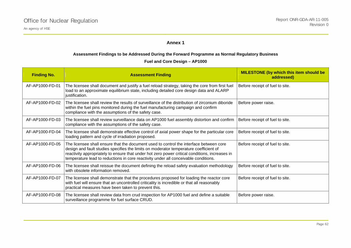
PROTECTIVE MARKING IF APPLICABLE
Office for Nuclear Regulation Report ONR-GDA-AR-11-005
An agency of HSE Revision 0
Annex 1
Page 62
Assessment Findings to be Addressed During the Forward Programme as Normal Regulatory Business
Fuel and Core Design – AP1000
Finding No. Assessment Finding MILESTONE (by which this item should be
addressed)
AF-AP1000-FD-01 The licensee shall document and justify a fuel reload strategy, taking the core from first fuel load to an approximate equilibrium state, including detailed core design data and ALARP justification.
Before receipt of fuel to site.
AF-AP1000-FD-02 The licensee shall review the results of surveillance of the distribution of zirconium diboride within the fuel pins monitored during the fuel manufacturing campaign and confirm compliance with the assumptions of the safety case.
Before power raise.
AF-AP1000-FD-03 The licensee shall review surveillance data on AP1000 fuel assembly distortion and confirm compliance with the assumptions of the safety case.
Before receipt of fuel to site.
AF-AP1000-FD-04
The licensee shall demonstrate effective control of axial power shape for the particular core loading pattern and cycle of irradiation proposed.
Before receipt of fuel to site.
AF-AP1000-FD-05
The licensee shall ensure that the document used to control the interface between core design and fault studies specifies the limits on moderator temperature coefficient of reactivity appropriately to ensure that under hot zero power critical conditions, increases in temperature lead to reductions in core reactivity under all conceivable conditions.
Before receipt of fuel to site.
AF-AP1000-FD-06
The licensee shall reissue the document defining the reload safety evaluation methodology with obsolete information removed.
Before receipt of fuel to site.
AF-AP1000-FD-07
The licensee shall demonstrate that the procedures proposed for loading the reactor core with fuel will ensure that an uncontrolled criticality is incredible or that all reasonably practical measures have been taken to prevent this.
Before receipt of fuel to site.
AF-AP1000-FD-08
The licensee shall review data from crud inspection for AP1000 fuel and define a suitable surveillance programme for fuel surface CRUD.
Before power raise.

PROTECTIVE MARKING IF APPLICABLE
Office for Nuclear Regulation An agency of HSE
Report ONR-GDA-AR-11-005Revision 0
Annex 1
Page 63
Assessment Findings to be Addressed During the Forward Programme as Normal Regulatory Business
Fuel and Core Design – AP1000
Finding No. Assessment Finding MILESTONE (by which this item should be
addressed)
AF-AP1000-FD-09
The licensee shall substantiate acceptance criteria for surveillance of surface crud based on measurements of the effect of representative crud on flow resistance and on an assessment of impact on margins to safety limits.
Before receipt of fuel to site.
AF-AP1000-FD-10
The licensee shall provide suitable documented justification for the general use of the W3 or a suitable alternative correlation outside the range of the WRB2M correlation.
Before receipt of fuel to site.
AF-AP1000-FD-11
The licensee shall review as-built flow rates and reflect conclusions for flow-induced wear in the maintenance schedule for affected components.
Before power raise.
AF-AP1000-FD-12
The licensee shall provide further justification of the limits on cladding temperature and stress required to ensure adequate ductility in dry storage.
Before receipt of fuel to site.
Note: It is the responsibility of the Licensees / Operators to have adequate arrangements to address the Assessment Findings. Future Licensees / Operators can adopt alternative means to those indicated in the findings which give an equivalent level of safety. For Assessment Findings relevant to the operational phase of the reactor, the Licensees / Operators must adequately address the findings during the operational phase. For other Assessment Findings, it is the regulators' expectation that the findings are adequately addressed no later than the milestones indicated above.
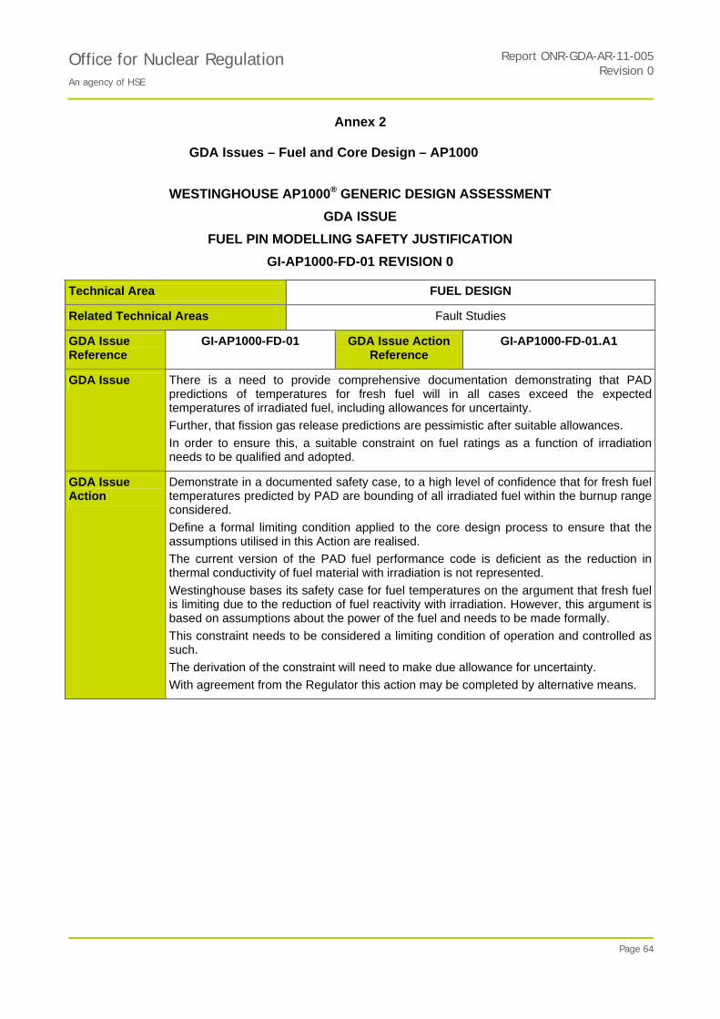
PROTECTIVE MARKING IF APPLICABLE
Report ONR-GDA-AR-11-005Office for Nuclear Regulation An agency of HSE
Revision 0
Annex 2
Page 64
GDA Issues – Fuel and Core Design – AP1000
WESTINGHOUSE AP1000® GENERIC DESIGN ASSESSMENT
GDA ISSUE
FUEL PIN MODELLING SAFETY JUSTIFICATION
GI-AP1000-FD-01 REVISION 0
Technical Area FUEL DESIGN
Related Technical Areas Fault Studies
GDA Issue Reference
GI-AP1000-FD-01 GDA Issue Action Reference
GI-AP1000-FD-01.A1
GDA Issue There is a need to provide comprehensive documentation demonstrating that PAD predictions of temperatures for fresh fuel will in all cases exceed the expected temperatures of irradiated fuel, including allowances for uncertainty.
Further, that fission gas release predictions are pessimistic after suitable allowances.
In order to ensure this, a suitable constraint on fuel ratings as a function of irradiation needs to be qualified and adopted.
GDA Issue Action
Demonstrate in a documented safety case, to a high level of confidence that for fresh fuel temperatures predicted by PAD are bounding of all irradiated fuel within the burnup range considered.
Define a formal limiting condition applied to the core design process to ensure that the assumptions utilised in this Action are realised.
The current version of the PAD fuel performance code is deficient as the reduction in thermal conductivity of fuel material with irradiation is not represented.
Westinghouse bases its safety case for fuel temperatures on the argument that fresh fuel is limiting due to the reduction of fuel reactivity with irradiation. However, this argument is based on assumptions about the power of the fuel and needs to be made formally.
This constraint needs to be considered a limiting condition of operation and controlled as such.
The derivation of the constraint will need to make due allowance for uncertainty.
With agreement from the Regulator this action may be completed by alternative means.

PROTECTIVE MARKING IF APPLICABLE
Report ONR-GDA-AR-11-005Office for Nuclear Regulation An agency of HSE
Revision 0
Annex 2
Page 65
WESTINGHOUSE AP1000® GENERIC DESIGN ASSESSMENT
GDA ISSUE
FUEL PIN MODELLING SAFETY JUSTIFICATION
GI-AP1000-FD-01 REVISION 0
Technical Area FUEL DESIGN
Related Technical Areas Fault Studies
GDA Issue Reference
GI-AP1000-FD-01 GDA Issue Action Reference
GI-AP1000-FD-01.A2
GDA Issue Action
Present a formal safety justification of the uncertainty of the current models of fission gas release and their limits of applicability.
The current version of the PAD fuel performance code is deficient as the empirical fission gas release model does not include a gas release threshold model. Consequentially the prediction of the rate of gas release tends to be too high initially, and then too low later.
Westinghouse bases its safety case for fuel pin pressures on the argument that empirical data can be used as a basis for prediction of fission gas release, but AP1000 envisages operating at fuel pin ratings and irradiations in excess of the current bulk of the data.
This brings into question the basis for the assessment of uncertainty in the current safety case and requires a thorough justification of its statistical basis at the limiting conditions of relevance.
With agreement from the Regulator this action may be completed by alternative means.

PROTECTIVE MARKING IF APPLICABLE
Report ONR-GDA-AR-11-005Office for Nuclear Regulation An agency of HSE
Revision 0
Annex 2
Page 66
WESTINGHOUSE AP1000® GENERIC DESIGN ASSESSMENT
GDA ISSUE
TOLERABILITY OF DEPRESSURISATION FORCES IN A LARGE BREAK LOSS OF COOLANT ACCIDENT (LBLOCA)
GI-AP1000-FD-02 REVISION 0
Technical Area FUEL DESIGN
Related Technical Areas Fault Studies
GDA Issue Reference
GI-AP1000-FD-02 GDA Issue Action Reference
GI-AP1000-FD-02.A1
GDA Issue Demonstrate that pressure forces associated with the depressurisation of the primary circuit are sufficiently limited that a coolable geometry is maintained in the core.
GDA Issue Action
Present arguments and analysis of the impact of depressurisation loads from large LOCA on the analysis of loss of coolable geometry.
ONR requires a suitable set of safety arguments and evidence to demonstrate that, in the event of a large LOCA, the reactor pressure vessel internals will not be damaged sufficiently for the assumptions of the safety case to be invalid. This needs to be documented in an assessment report and referenced from the safety report.
Please note that an acceptable case for preclusion of the double-ended break has not been made, and in any event, the fault is still likely to be viewed as risk significant, so its consequences would need to be considered even if it were not deemed to be a Design Basis fault.
With agreement from the Regulator this action may be completed by alternative means.

PROTECTIVE MARKING IF APPLICABLE
Office for Nuclear Regulation An agency of HSE
Report ONR-GDA-AR-11-005Revision 0
Annex 2
Page 67
WESTINGHOUSE AP1000® GENERIC DESIGN ASSESSMENT
GDA ISSUE
USE OF THE BEACON CODE FOR ON-LINE COMPLIANCE
GI-AP1000-FD-03 REVISION 0
Technical Area FUEL DESIGN
Related Technical Areas Fault Studies
GDA Issue Reference
GI-AP1000-FD-03 GDA Issue Action Reference
GI-AP1000-FD-03.A1
GDA Issue Provide a safety case to demonstrate compliance with the fuel and fault study limits in the event of an unrevealed failure of the BEACON code.
GDA Issue Action
Identify the processes in which BEACON contributes directly or indirectly to nuclear safety and the hazards that arise should the BEACON software act in a malignant manor.
Evaluate by fault studies the risk associated with each failure sequence and demonstrate that no further measures to mitigate the risk of BEACON failure are reasonably practical.
While significant effort has been made to demonstrate that BEACON is a useful and reliable tool, these arguments are only of limited use. While reliance is placed on the correct functioning of a system, a high safety classification is indicated and this may not be reasonably achievable.
The NII safety assessment principles advise that design basis analysis should provide an input into safety classification and the requirements for systems providing a safety function. Accordingly, a safety case must address the consequences of the software failing or an unrevealed failure becoming apparent during a fault. The safety analysis process for BEACON should be similar to the consideration of failure in any other system i.e. it should examine potential hazards and ultimately quantify risk.
ONR expects a detailed justification that the processes in which BEACON is used are robust against BEACON failure in normal operation and in simultaneous faults and that risk is ALARP.
Usually acceptable mitigation of faults can be claimed if an independent means exists for the operator to verify that the reactor remains compliant with the safety case and that these are likely to be used on a frequency determined by the risk assessment.
With agreement from the Regulator this action may be completed by alternative means.
Further explanatory / background information on the GDA Issues for this topic area can be found at:
GI- AP1000-FD-01 Revision 0 Ref. 80
GI- AP1000-FD-02 Revision 0 Ref. 81
GI- AP1000-FD-03 Revision 0 Ref. 82