fuel cycle research and development: core materials ... cycle research and development: core...
TRANSCRIPT
Fuel Cycle Research and Development: Core Materials Technologies Overview - Fast Reactor and LWR Fuel Cladding
Stuart A. Maloy Core Materials Technical Lead for Fuels Los Alamos National Laboratory DOE NE Materials-Cross-Coordination Webinar July 30, 2013 LA-UR-13-25972
2
Contributors
LANL: Tarik Saleh, Toby Romero, Bill Crooks, Ed Garcia, Rob Aikin jr., Osman Anderoglu, Ming Tang, Sara Perez-Berquist, Mark Bourke, Don Brown, Bjorn Clausen
PNNL: Mychailo Toloczko, Glenn Grant, David Senor, Jim Buelt INL: Jim Cole, Randy Fielding, Jian Gan, Mitch Meyer, Bulent H.
Sencer, Emmanuel Perez, Michael Teague
ORNL: T.S. Byun, David Hoelzer, M. Brady, K. Terrani, M. Fechter, L. Snead, B. Pint
Techsource: F. Garner
UCSB: G.R. Odette
UCB: P. Hosemann
SDSMT: M. West, B. Jasthi
ATI Inc.- M. Ferry, Jean Stewart
TAMU – Haiyan Wang
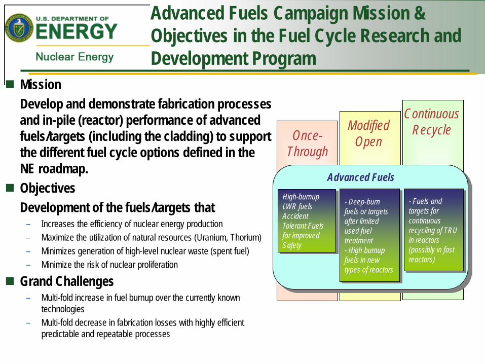
Advanced Fuels Campaign Mission & Objectives in the Fuel Cycle Research and Development Program
Mission Develop and demonstrate fabrication processes
and in-pile (reactor) performance of advanced fuels/targets (including the cladding) to support the different fuel cycle options defined in the NE roadmap.
Objectives Development of the fuels/targets that
– Increases the efficiency of nuclear energy production – Maximize the utilization of natural resources (Uranium, Thorium) – Minimizes generation of high-level nuclear waste (spent fuel) – Minimize the risk of nuclear proliferation
Grand Challenges – Multi-fold increase in fuel burnup over the currently known
technologies – Multi-fold decrease in fabrication losses with highly efficient
predictable and repeatable processes
Once- Through
Modified Open
Continuous Recycle
Advanced Fuels
High-burnup LWR fuels Accident Tolerant Fuels for improved Safety
- Deep-burn fuels or targets after limited used fuel treatment - High burnup fuels in new types of reactors
- Fuels and targets for continuous recycling of TRU in reactors (possibly in fast reactors)

4
Approach to Enabling a Multi-fold Increase in Fuel Burnup over the Currently Known Technologies
Coa
ting
Line
rs
Adv
ance
d A
lloys
F/M
Ste
els
Adv
ance
d A
lloys
Cr Si Al
Increasing content
F/M
Ste
els
HT-
9
Adv
ance
d F/
M
Ste
els,
e.g
. NF6
16
OD
S S
teel
s
Adv
ance
d A
lloys
200 dpa 300 dpa 400 dpa
500 C 600 C 700 C
Reduced embrittlement, swelling, creep
Enhancements with Fabrication Complexity
Enhancements with Fabrication Complexity Enhancements with Fabrication Complexity
Different Reactor options to change
requirements LFR, GFR
FCCI
Radiation Temperature
Corrosion
Ultimate goal: Develop advanced materials immune to fuel, neutrons and coolant interactions under specific reactor environments
Ultra-high Burnup Fuels
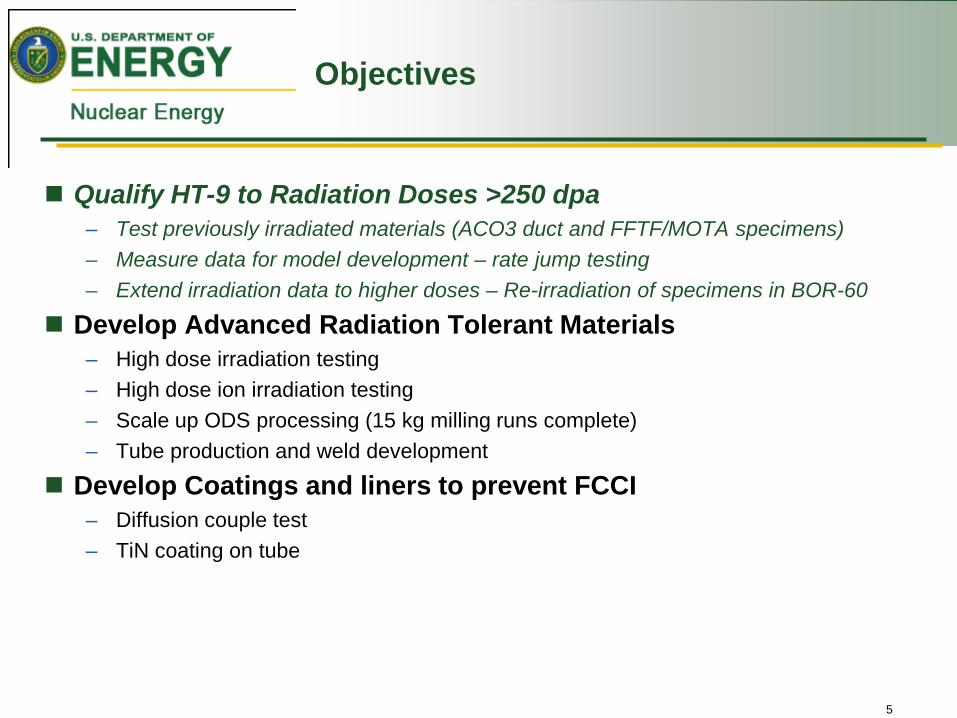
Objectives
Qualify HT-9 to Radiation Doses >250 dpa – Test previously irradiated materials (ACO3 duct and FFTF/MOTA specimens) – Measure data for model development – rate jump testing – Extend irradiation data to higher doses – Re-irradiation of specimens in BOR-60
Develop Advanced Radiation Tolerant Materials – High dose irradiation testing – High dose ion irradiation testing – Scale up ODS processing (15 kg milling runs complete) – Tube production and weld development
Develop Coatings and liners to prevent FCCI – Diffusion couple test – TiN coating on tube
5
6
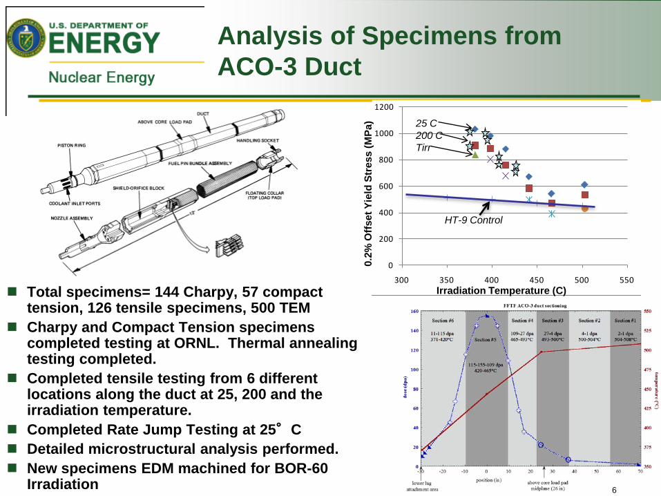
Analysis of Specimens from ACO-3 Duct
Total specimens= 144 Charpy, 57 compact tension, 126 tensile specimens, 500 TEM
Charpy and Compact Tension specimens completed testing at ORNL. Thermal annealing testing completed.
Completed tensile testing from 6 different locations along the duct at 25, 200 and the irradiation temperature.
Completed Rate Jump Testing at 25°C Detailed microstructural analysis performed. New specimens EDM machined for BOR-60
Irradiation
0
200
400
600
800
1000
1200
300 350 400 450 500 550
HT-9 Control
Irradiation Temperature (C)
0.2%
Offs
et Y
ield
Str
ess
(MPa
) 25 C 200 C Tirr

Tensile Testing Completed on High Dose Irradiated F/M Steels
LANL recently shipped samples to Russia for re-irradiation in BOR-60 through CRADA with Terrapower.
LANL completed rate jump tests on specimens from the ACO-3 duct. Data is being coordinated with model development.
Stress-strain curves measured on irradiated HT-9 while performing rate jump testing
Diagram showing specimen cut plan from ACO-3 duct for re-irradiation in BOR-60

8 Managed by UT-Battelle for the Department of Energy
Study on Annealing Recovery of Fracture Toughness in ACO-3 Duct HT9 by Specimen Reusing Technique
These Charpy specimen halves were reused for J-R tests: annealed, notched, precracked, and fracture (J-R)-tested.
L-direction
0
1
2
3
4
5
-200 -100 0 100 200 300 400
Temperature, oC
Abs
orbe
d en
ergy
, J
2E5-L(503°C,3.2dpa)2E4-L(503°C,3.1dpa)6C8-L(380°C,20.5dpa)4C3-L(467°C,87.9dpa)5C2-L(441°C,146.9dpa)4C2-L(465°C,95.7dpa)5C3-L(438°C,147.6dpa)6C5-L(398°C,41.7dpa)6C6-L(396°C,38.8dpa)6C3-L(412°C,95.8dpa)6C2-L(396°C,38.8dpa)6C9-L(382°C,23.3dpa)
Subsize Charpy specimen from ACO-3 Duct
3.05 (thickness)x4x27 mm
Pieces after fracture(J-R) test An annealed half
Charpy impact test data
9 Managed by UT-Battelle for the Department of Energy
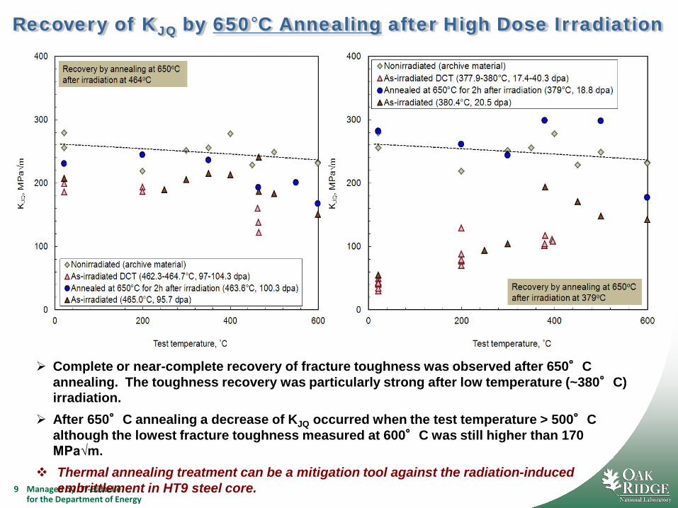
Recovery of KJQ by 650°C Annealing after High Dose Irradiation
Complete or near-complete recovery of fracture toughness was observed after 650°C annealing. The toughness recovery was particularly strong after low temperature (~380°C) irradiation.
After 650°C annealing a decrease of KJQ occurred when the test temperature > 500°C although the lowest fracture toughness measured at 600°C was still higher than 170 MPa√m.
Thermal annealing treatment can be a mitigation tool against the radiation-induced embrittlement in HT9 steel core.

Objectives
Qualify HT-9 to Radiation Doses >250 dpa – Test previously irradiated materials (ACO3 duct and FFTF/MOTA specimens) – Measure data for model development – rate jump testing – Extend irradiation data to higher doses – Re-irradiation of specimens in BOR-60
Develop Advanced Radiation Tolerant Materials – High dose irradiation testing – High dose ion irradiation testing – Scale up ODS processing (15 kg milling runs complete) – Tube production and weld development
Develop Coatings and liners to prevent FCCI – Diffusion couple test – TiN coating on tube
10
11
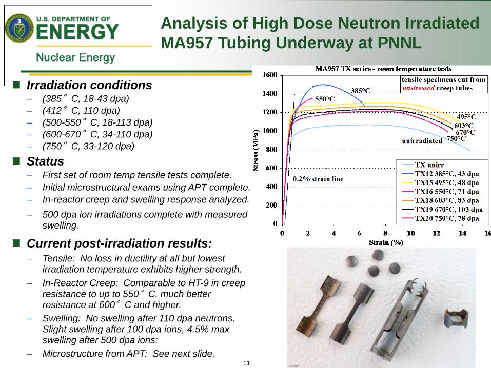
Analysis of High Dose Neutron Irradiated MA957 Tubing Underway at PNNL
Irradiation conditions – (385°C, 18-43 dpa) – (412°C, 110 dpa) – (500-550°C, 18-113 dpa) – (600-670°C, 34-110 dpa) – (750°C, 33-120 dpa)
Status – First set of room temp tensile tests complete. – Initial microstructural exams using APT complete. – In-reactor creep and swelling response analyzed. – 500 dpa ion irradiations complete with measured
swelling.
Current post-irradiation results: – Tensile: No loss in ductility at all but lowest
irradiation temperature exhibits higher strength. – In-Reactor Creep: Comparable to HT-9 in creep
resistance to up to 550°C, much better resistance at 600°C and higher.
– Swelling: No swelling after 110 dpa neutrons. Slight swelling after 100 dpa ions, 4.5% max swelling after 500 dpa ions:
– Microstructure from APT: See next slide.

High Dose MA957 ODS Ferritic Alloy APT Exams at UC Berkeley
12
Objective – Study microstructure of neutron irradiated ODS ferritic steel, with emphasis on oxide particle morphology.
Material - MA957 from in-reactor pressurized tube creep specimens.
Preliminary APT examinations completed on specimens irradiated at 412, 550, 670, and 750°C to 109-121 dpa.
Initial Results MA957 pressurized tubes have a small
oxide particle size of ~2 nm similar to newer ODS steels such as 14YWT.
No obvious ballistic dissolution at these irradiation temperatures, but small difference in oxide particle population at 412°C.
Cr-rich alpha-prime clusters observed at 412°C irradiation temperature consistent with 14Cr composition.
Some grain boundary segregation.
TiO signal from oxide particles
Cr-rich
alpha prime
MA957 – 412°C, 109 dpa

Scale Up Production of 14YWT Ferritic Alloy (Heat FCRD-NFA1)
4 of 4 ball milling runs completed by Zoz V540-01: 15 kg of coarse (>150 µm) powder V540-02: 15 kg of medium (45-150 µm) and fine
(<45 µm) powder V540-03: 15 kg medium, fine and small amount
of V540-01 coarse powder V540-04: 15kg medium, fine powder mixed with
yttria for the oxide dispersion.
V540-02 Ball Milled 40 h MET. SPECIMEN NO: 12-0581 LOAD in grams: 200
Indent no. HV 1 723.57 2 744.47 3 726.78 4 713.14 5 700.18 6 768.03
AVERAGE = 729.36 STD = 23.99
0.0
0.1
0.2
0.3
0.4
0.5
0.6
0.7
0.8
0.9
1.0
0 20 40 60 80 100 120 140 160 180 200 220
OTiY
Com
posi
tion
(wt.%
)
Line Scan Length (µm)
EPMA showed 40 h ball milling distributed Y uniformly in fine and medium powders
40 h ball milling did not distribute Y uniformly in coarse powders
Mechanical testing underway.

High Toughness ODS Ferritic Alloy Development in FC R&D (I-NERI)
• Development and Characterization of Nanoparticle Strengthened Dual Phase Alloys for High Temperature Nuclear Reactor Applications
• To develop high toughness NFAs* for high temperature (700ºC) high dose (>300 dpa) applications: 100 MPa√m over the range of RT - 700°C.
• Use grain boundary strengthening/modification techniques.
• ORNL (TS Byun & D.T. Hoelzer) – KAERI (JH Yoon)
• Dec. 1, 2010 – Nov. 30, 2013
* Nanostructured Ferritic Alloys (NFAs) vs. Oxide Dispersion Strengthened (ODS) Alloys

Characterization
Production of Base Materials (9YWTV)
Two alloy power heats (8 kg each) have been produced by gas atomization process at ATI Powder Metals: Fe-9Cr-2W-0.4Ti-0.2V-0.12C+0.3Y2O3 & Fe-9Cr-2W-0.4Ti-0.2V-0.05C+0.3Y2O3
Extruded below 850°C Cut into 4 inch long blocks
Ball milling for 40 hours in Zoz CM08 machine (6 loads)/ Canned & degassed (6 cans, 920g each)
Goals of Yrs 2 & 3: • Post-Extrusion TMT Optimization • Micro & High Temp. Characterization • Feedbacks for new processing

Preliminary Results for Fracture Toughness
o 9YWTV-PM2-850C-200m: Annealed at 850°C for 200 minutes.
o 9YWTV-PM2-850C-20H: Annealed at 850°C for 20 hours.
o 9YWTV-PM2-900C-50%R: Hot-rolled for multi-step 50% reduction after annealing at 900°C.
Fracture toughness can be significantly improved by some controlled rolling, and the KJQ values are as high as those of FM steels.
Further development/optimization of processing is underway.
14YWT-PM1R

Fabrication of Cladding Tubes from ODS alloys
3 cans were designed and fabricated for producing thick wall tubes from the ODS 14YWT and 9Cr-ODS alloys
Powder has been ball milled, canned and hot extruded. Potential collaboration with Y. de Carlan, CEA, Saclay to
produce cladding tubes High-Precision Tube Roller Pilger equipment at CEA
L. Toualbi et. al, Journal of Nuclear Materials (2012) In Press DOI:10.1016/j.jnucmat.2011.12.013

Objectives
Qualify HT-9 to Radiation Doses >250 dpa • Test previously irradiated materials (ACO3 duct and FFTF/MOTA specimens) • Measure data for model development – rate jump testing • Extend irradiation data to higher doses – Re-irradiation of specimens in BOR-60
Develop Advanced Radiation Tolerant Materials • High dose irradiation testing • High dose ion irradiation testing • Scale up ODS processing (15 kg milling runs complete) • Tube production and weld development
Develop Coatings and liners to prevent FCCI • Diffusion couple test • TiN coating on tube
18
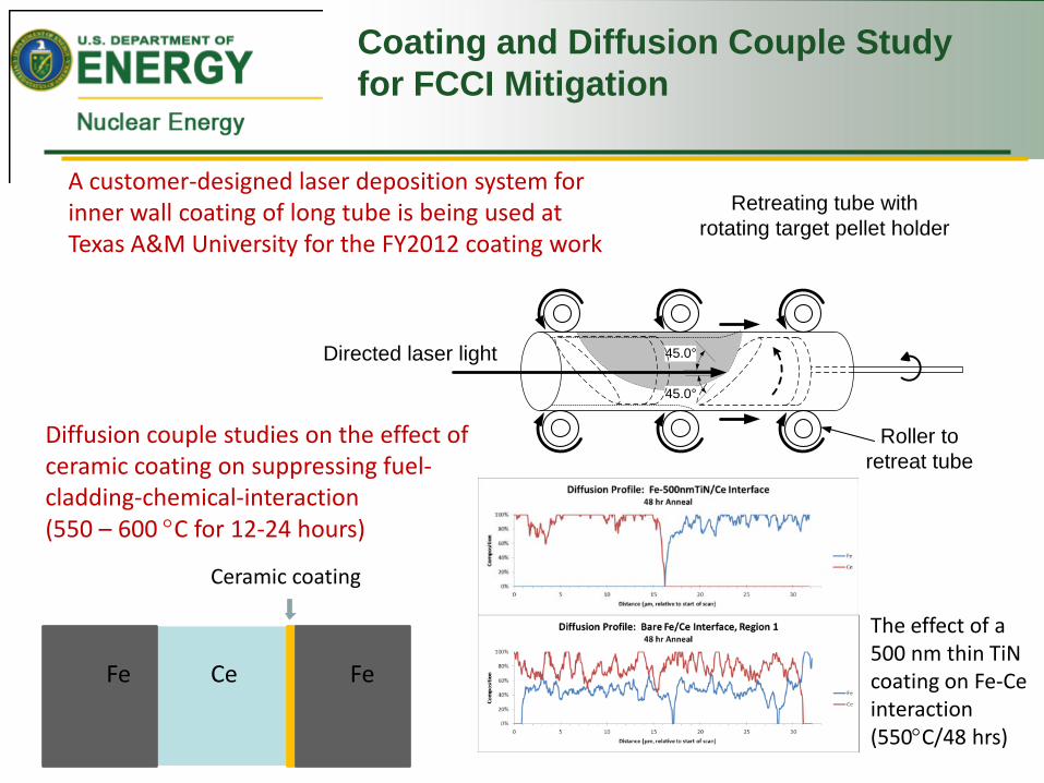
Directed laser light 45.0°
45.0°
Retreating tube withrotating target pellet holder
Roller to retreat tube
A customer-designed laser deposition system for inner wall coating of long tube is being used at Texas A&M University for the FY2012 coating work
Ce Fe Fe
Ceramic coating
Diffusion couple studies on the effect of ceramic coating on suppressing fuel-cladding-chemical-interaction (550 – 600 °C for 12-24 hours)
The effect of a 500 nm thin TiN coating on Fe-Ce interaction (550°C/48 hrs)
Coating and Diffusion Couple Study for FCCI Mitigation

Met Level 2 Milestone to Fabricate Coated Cladding Tube for Fuels Irradiation in ATR
TiN Inner coating formed on glass tube to test TiN coating process
20
Successful run performed on HT-9 tube for ATR irradiation.

Designed a diffusion couple irradiation experiment in ATR (550 °C for 50 days) to meet the temperature and post-irradiation-examination requirements.
Diffusion couple thermal annealing studies on chemical compatibility at the cladding – liner interface (HT-9 vs. V or Zr). (704 – 815 °C for 50-200 hours)
704 °C for 200 hrs
Interaction zone thickness: 0.5 µm Interdiffusion zone thickness: 18 µm
Interaction zone thickness: 8 µm Interdiffusion zone thickness: 28 µm
Diffusion Couple Studies on FCCI Mitigation
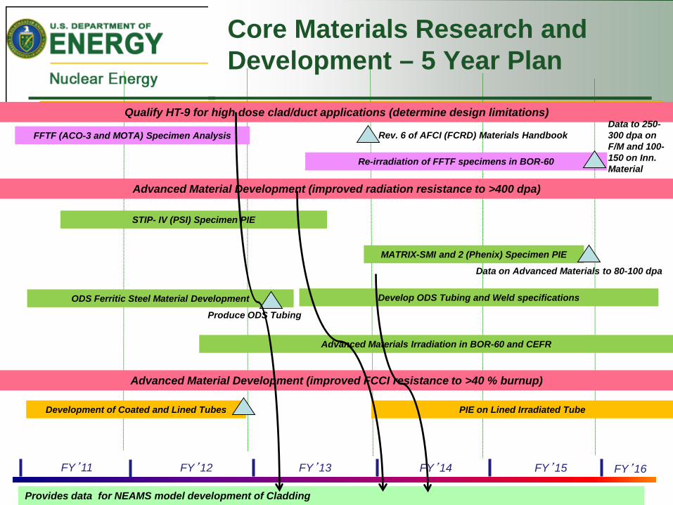
Core Materials Research and Development – 5 Year Plan
FY’16 FY’15 FY’14 FY’11 FY’13 FY’12
STIP- IV (PSI) Specimen PIE
MATRIX-SMI and 2 (Phenix) Specimen PIE
Re-irradiation of FFTF specimens in BOR-60
Provides data for NEAMS model development of Cladding
FFTF (ACO-3 and MOTA) Specimen Analysis
Advanced Material Development (improved radiation resistance to >400 dpa)
Qualify HT-9 for high dose clad/duct applications (determine design limitations)
ODS Ferritic Steel Material Development
Produce ODS Tubing
Advanced Materials Irradiation in BOR-60 and CEFR
Advanced Material Development (improved FCCI resistance to >40 % burnup)
Development of Coated and Lined Tubes
Rev. 6 of AFCI (FCRD) Materials Handbook
PIE on Lined Irradiated Tube
Develop ODS Tubing and Weld specifications
Data to 250-300 dpa on F/M and 100-150 on Inn. Material
Data on Advanced Materials to 80-100 dpa

23
Grand Challenge for Core Materials for Next Generation LWR Fuels
Develop and test advanced alloys for Next Generation LWR Fuels with Enhanced Performance and Safety and Reduced Waste Generation – Low Thermal Neutron Crossection
• Element selection (e.g. Zr, Mg) • Reduce cladding wall thickness
– Irradiation tolerant to at least 15 dpa • Resists swelling and irradiation creep • Does not accumulate damage • Stable microstructure (resists RIS)
– Mechanically robust under loading and transportation conditions – Compatibility with Fuel and Coolant
• Resists stress corrosion cracking • Resists accident conditions (e.g. high temperature steam) • Resists abnormal coolant changes (e.g. salt water)
– Weldable and Processed into tube form • Maintain hermetic seal under normal/off-normal conditions

Objectives
Measure Kinetics of Oxidation in Steam • Steam oxidation testing up to 1300C (ORNL) • Fundamental oxidation studies in steam (LANL)
Develop Processing Techniques to produce thin-walled tubing • Producing tubing of MA-956 with 250 micron thick walls (LANL) • Measuring mechanical properties of thin walled tubes (ORNL) • Weld development on thin-walled tubing (INL and ORNL)
Measure Radiation Tolerance of ATF ferritic alloys • Ion irradiated materials (LANL) • ATR irradiated materials
- Tensile testing (LANL) - Fracture toughness testing (ORNL)
Developing Improved ATF alloy (ORNL) • Weld development for improved ATF alloy (INL) • Mechanical testing and ion irradiations (LANL)
Develop Advanced ATF alloy (LANL) • Production of Mo tubing using FB-CVD processing
25
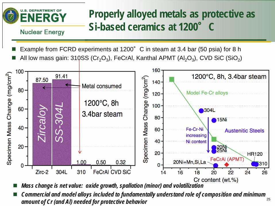
Properly alloyed metals as protective as Si-based ceramics at 1200°C
Example from FCRD experiments at 1200°C in steam at 3.4 bar (50 psia) for 8 h All low mass gain: 310SS (Cr2O3), FeCrAl, Kanthal APMT (Al2O3), CVD SiC (SiO2)
Mass change is net value: oxide growth, spallation (minor) and volatilization Commercial and model alloys included to fundamentally understand role of composition and minimum
amount of Cr (and Al) needed for protective behavior
Zirc
aloy
S
S-3
04L

Measurements on hydrogen evolution performed in steam
Hydrogen Production begins in Zircaloy-4 at ~700C and in 304L at ~1000C Similar testing will be performed on all advanced alloys in FY13
Zirc-4 in N2 containing ~25%
water vapor to 1100°C
304 in N2 containing ~25%
water vapor to 1100°C

Mechanical Property Testing
Ring-compression Load-Displacement curves with Zry-4 oxidized at 1200°C for CP-ECR=30%
Ring-compression Load-Displacement curves with SS-317 oxidized at 1200°C for CP-ECR=30%
Brittle Ductile
Both samples have the same OD and wall thickness, and were oxidized at 1200°C for ~900s

Summary of Oxidation Kinetics Screening Tests
A series of ~35 conditions has been carried of on silica formers (i.e. SiC) chromia formers (i.e. stainless steels) and alumina former (i.e. alumina forming alloys “AFA’s”.)
Results are dependent on temperature, time, pressure, and velocity and therefore the specific beyond LOCA scenario may be critical. However, a subset of attractive materials (CVD and NITE SiC, 310 stainless, and AFA’s) have been identified.
A series of papers have been submitted: T. Cheng : “Oxidation of Fuel Cladding Materials in Steam Environments at High
Temperature and Pressure.” submitted Journal of Nuclear Materials. K. Terrani et. Al. “Protection of Zirconium by Alumina- and Chromia-Forming Steels
under High-Temperature Steam Exposure” to be submitted Journal of Nuclear Materials.
J. Keiser High Temperature Oxidation of Candidate Advanced Iron-Based Alloy Cladding Materials in Steam-Hydrogen Environments,” Proceedings of Nuclear Fuels and Structural Materials for the Next Generation Nuclear Reactors, Chicago, Illinois, June 2012.
B. A. Pint, et. al. “High Temperature Oxidation of Fuel Cladding Candidate Materials in Steam-Hydrogen Environments” 8th International Symposium on High-Temperature Corrosion and Protection of Materials

Core Materials Research and Development ATF Clad Development - 5 Year Plan
FY’16 FY’15 FY’14 FY’13 FY’12
Develop Steel thin-walled tubing
Advanced Material Development (improved accident tolerance for LWR’s)
Oxidation testing in Steam on
Advanced Steel Alloys
Thin walled tube development for advanced steel alloys
ATR irradiation of ATF cladding with advanced fuels
Weld development for thin walled tubing
Oxidation testing in Steam on Advanced Steel Alloys
Irradiation testing and PIE on ATF clad materials
Corrosion testing on ATF clad materials
IASCC testing on ATF clad materials
Produce thin walled tubing for ATF irradiation
Oxidation testing in Steam on Advanced Steel Alloys
after irradiation
Qualified weld procedure for thin walled tubing
Report on initial results of LOCA testing on ATF clad materials
Final report of LOCA testing on ATF clad materials
Report on irradiation testing of clad materials to at least 15 dpa
Summary report on corrosion resistance of ATF clad materials
Coordinate and collaborate with ATF fuel development with industry through FOA and NEUP projects including the IRP on development of ATF
FY’17

Materials Integration and University and International Collaborations
Integrate FCRD Core Materials Activities • Fuels Core Materials Work- (INL, PNNL, LANL, ORNL, LLNL)
- Materials teleconferences monthly • University Materials Research (attend university review, review quarterly progress
reports) - UCSB- Optimized Compositional Design and Processing-Fabrication Paths for Larger Heats of Nanostructured
Ferritic Alloys - TAMU-Bulk nanostructured austenitic stainless steels with enhanced radiation tolerance - U. Ill Urb/Champaign–Development of Austenitic ODS Strengthened Alloys for Very High Temperature Applications
• ATR Reactor Irradiations (provide materials and preparing to collaborate in testing) Working group meetings and Workshops
• NE Materials Cross-cut Webinars in August 2012 and July-August 2013 International Collaborations
• INERI-GETMAT- 14Cr ODS material development • INERI-KAERI- 9Cr ODS material development • Participant in IAEA Coordinated Research Project on “Benchmarking of Structural
Materials Pre-selected for Advanced Nuclear Reactors” – met in Vienna, May 2-6, 2011. • DOE-CIAE Collaboration – Proposed irradiation in CEFR • DOE-Russia – Proposed irradiation in BOR-60 • LANL-Terrapower CRADA – proposed irradiation of ACO-3 specimens in BOR-60