for mids jtrs terminals - viasat, inc....for mids jtrs terminals mids jtrs platform ... audio output...
TRANSCRIPT
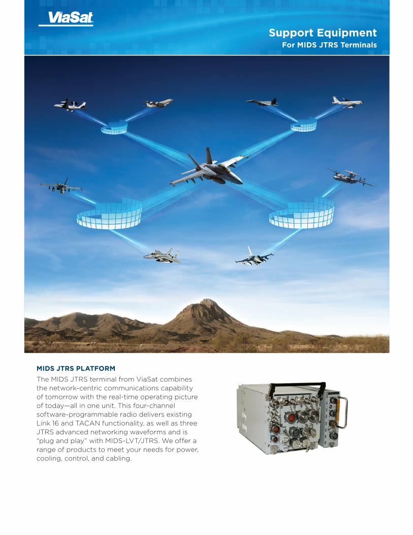
Support EquipmentFor MIDS JTRS Terminals
MIDS JTRS PLATFORMThe MIDS JTRS terminal from ViaSat combines the network-centric communications capability of tomorrow with the real-time operating picture of today—all in one unit. This four-channel software-programmable radio delivers existing Link 16 and TACAN functionality, as well as three JTRS advanced networking waveforms and is “plug and play” with MIDS-LVT/JTRS. We offer a range of products to meet your needs for power, cooling, control, and cabling.

Support Equipment for MIDS JTRS Terminals
ViaSat’s LVT/JTRS Mobile Unit is a transportable case for the MIDS JTRS and MIDS-LVT(1) terminal and its variants. It includes everything required to operate a MIDS-LVT(1) or a MIDS JTRS terminal—power, cooling, control, cabling, attenuator/terminator—and comes ready to use.
The following functions are supported:
» Power Control Panel
» MIDS-LVT/JTRS Power Supply 1U Configuration
» MIDS-LVT/JTRS Cooling Tray
» MIDS-LVT/JTRS Integrated Control Unit Cables
» MIDS-LVT/JTRS Voice Control Unit with W2 Cable
» W3, W4, and W7 Cables for MIDS
» W3 Cable for JTRS
» W16 Cable for JTRS
» B & C Power Cables for JTRS
» AC Power Cable, 12 ft, NEMA 5-15P Plug
» RPS-to-MT Interconnect Cable Set
» Fill Cable
» ETR Cable
» Ethernet Switch, 5-port
» RF Cable with Weinschel 40-30-33 30 dB 150 W Attenuator in Slide Out 2U Drawer
» Weinschel 1426-4 Terminator/Load
» User Guide
MIDS-LVT/JTRS MOBILE UNITSPECIFICATIONSDimensions (with covers) 27 x 28 x 39 in.
Dimensions (without covers) 27 x 28 x 28 in.
Weight with MIDS Terminal 227 lb and RPS
Input Power 115 VAC 60 Hz, 15 Amp
ORDERING INFORMATIONPN: 1136426 MIDS-LVT/JTRS Mobile Rack with Voice
Control Unit with microphone
PN: 1136427 MIDS-LVT/JTRS Mobile Rack with Voice Control Unit with headset
Front View
MIDS-LVT/JTRS Mobile Unit
Rear View
2
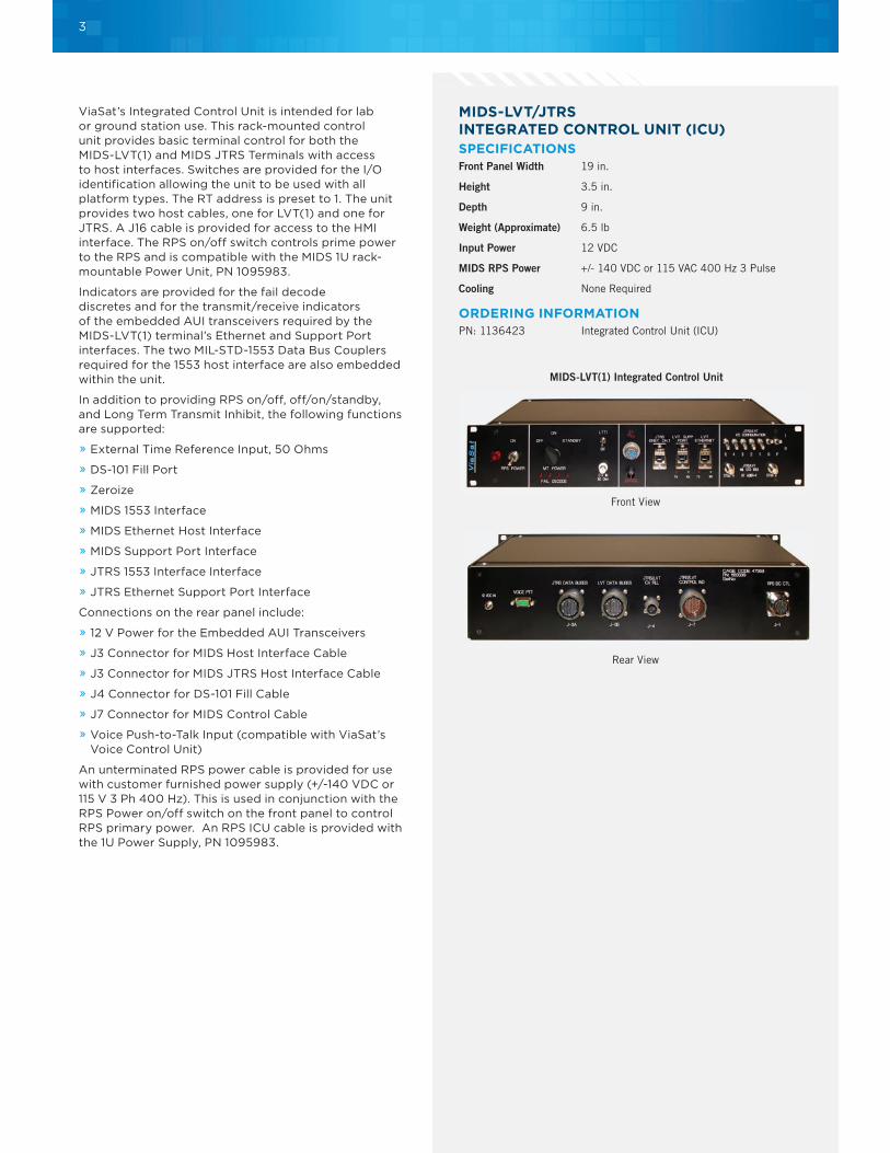
ViaSat’s Integrated Control Unit is intended for lab or ground station use. This rack-mounted control unit provides basic terminal control for both the MIDS-LVT(1) and MIDS JTRS Terminals with access to host interfaces. Switches are provided for the I/O identification allowing the unit to be used with all platform types. The RT address is preset to 1. The unit provides two host cables, one for LVT(1) and one for JTRS. A J16 cable is provided for access to the HMI interface. The RPS on/off switch controls prime power to the RPS and is compatible with the MIDS 1U rack-mountable Power Unit, PN 1095983.
Indicators are provided for the fail decode discretes and for the transmit/receive indicators of the embedded AUI transceivers required by the MIDS-LVT(1) terminal’s Ethernet and Support Port interfaces. The two MIL-STD-1553 Data Bus Couplers required for the 1553 host interface are also embedded within the unit.
In addition to providing RPS on/off, off/on/standby, and Long Term Transmit Inhibit, the following functions are supported:
» External Time Reference Input, 50 Ohms
» DS-101 Fill Port
» Zeroize
» MIDS 1553 Interface
» MIDS Ethernet Host Interface
» MIDS Support Port Interface
» JTRS 1553 Interface Interface
» JTRS Ethernet Support Port Interface
Connections on the rear panel include:
» 12 V Power for the Embedded AUI Transceivers
» J3 Connector for MIDS Host Interface Cable
» J3 Connector for MIDS JTRS Host Interface Cable
» J4 Connector for DS-101 Fill Cable
» J7 Connector for MIDS Control Cable
» Voice Push-to-Talk Input (compatible with ViaSat’s Voice Control Unit)
An unterminated RPS power cable is provided for use with customer furnished power supply (+/-140 VDC or 115 V 3 Ph 400 Hz). This is used in conjunction with the RPS Power on/off switch on the front panel to control RPS primary power. An RPS ICU cable is provided with the 1U Power Supply, PN 1095983.
MIDS-LVT/JTRSINTEGRATED CONTROL UNIT (ICU)SPECIFICATIONSFront Panel Width 19 in.
Height 3.5 in.
Depth 9 in.
Weight (Approximate) 6.5 lb
Input Power 12 VDC
MIDS RPS Power +/- 140 VDC or 115 VAC 400 Hz 3 Pulse
Cooling None Required
ORDERING INFORMATIONPN: 1136423 Integrated Control Unit (ICU)
Front View
MIDS-LVT(1) Integrated Control Unit
Rear View
3
Support Equipment for MIDS JTRS Terminals
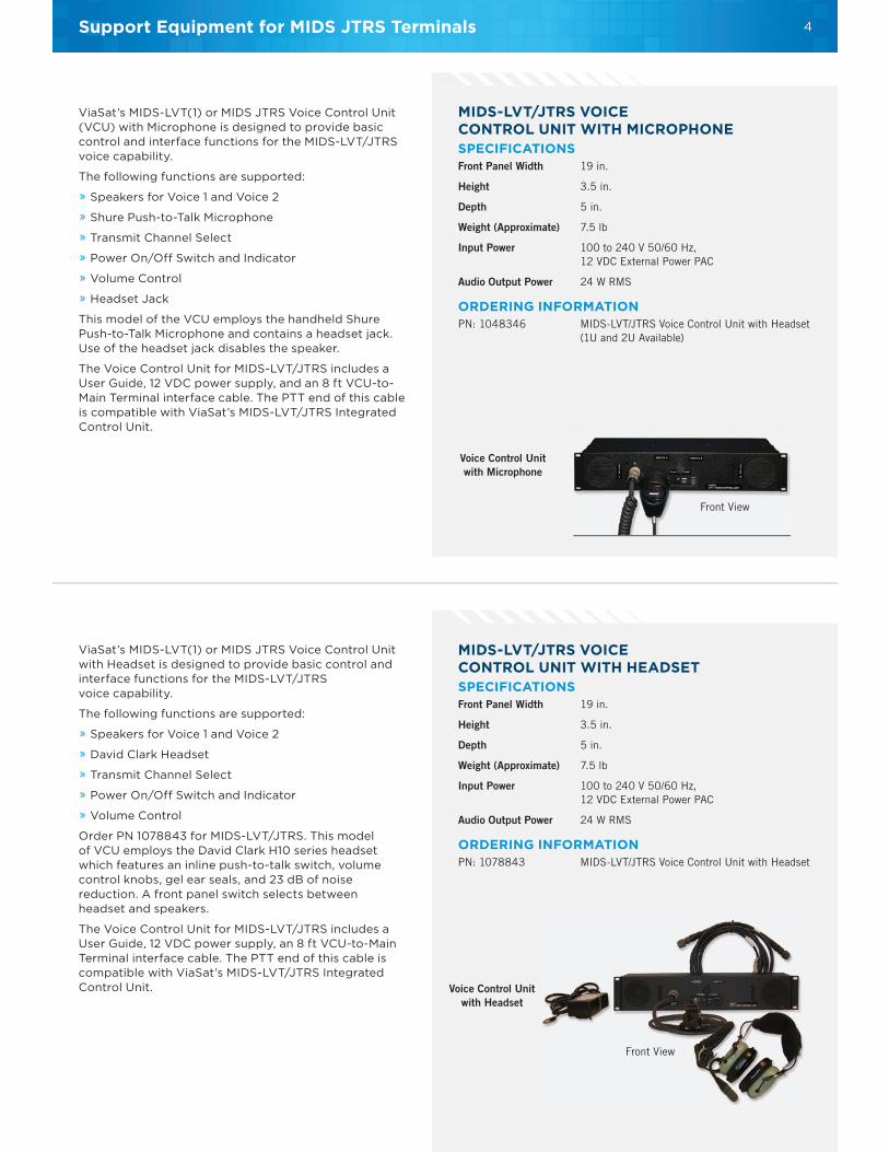
ViaSat’s MIDS-LVT(1) or MIDS JTRS Voice Control Unit (VCU) with Microphone is designed to provide basic control and interface functions for the MIDS-LVT/JTRS voice capability.
The following functions are supported:
» Speakers for Voice 1 and Voice 2
» Shure Push-to-Talk Microphone
» Transmit Channel Select
» Power On/Off Switch and Indicator
» Volume Control
» Headset Jack
This model of the VCU employs the handheld Shure Push-to-Talk Microphone and contains a headset jack. Use of the headset jack disables the speaker.
The Voice Control Unit for MIDS-LVT/JTRS includes a User Guide, 12 VDC power supply, and an 8 ft VCU-to-Main Terminal interface cable. The PTT end of this cable is compatible with ViaSat’s MIDS-LVT/JTRS Integrated Control Unit.
MIDS-LVT/JTRS VOICE CONTROL UNIT WITH MICROPHONESPECIFICATIONSFront Panel Width 19 in.
Height 3.5 in.
Depth 5 in.
Weight (Approximate) 7.5 lb
Input Power 100 to 240 V 50/60 Hz, 12 VDC External Power PAC
Audio Output Power 24 W RMS
ORDERING INFORMATIONPN: 1048346 MIDS-LVT/JTRS Voice Control Unit with Headset
(1U and 2U Available)
Front View
Voice Control Unit with Microphone
Front View
Voice Control Unit with Headset
MIDS-LVT/JTRS VOICE CONTROL UNIT WITH HEADSETSPECIFICATIONSFront Panel Width 19 in.
Height 3.5 in.
Depth 5 in.
Weight (Approximate) 7.5 lb
Input Power 100 to 240 V 50/60 Hz, 12 VDC External Power PAC
Audio Output Power 24 W RMS
ORDERING INFORMATIONPN: 1078843 MIDS-LVT/JTRS Voice Control Unit with Headset
ViaSat’s MIDS-LVT(1) or MIDS JTRS Voice Control Unit with Headset is designed to provide basic control and interface functions for the MIDS-LVT/JTRS voice capability.
The following functions are supported:
» Speakers for Voice 1 and Voice 2
» David Clark Headset
» Transmit Channel Select
» Power On/Off Switch and Indicator
» Volume Control
Order PN 1078843 for MIDS-LVT/JTRS. This model of VCU employs the David Clark H10 series headset which features an inline push-to-talk switch, volume control knobs, gel ear seals, and 23 dB of noise reduction. A front panel switch selects between headset and speakers.
The Voice Control Unit for MIDS-LVT/JTRS includes a User Guide, 12 VDC power supply, an 8 ft VCU-to-Main Terminal interface cable. The PTT end of this cable is compatible with ViaSat’s MIDS-LVT/JTRS Integrated Control Unit.
4

MIDS JTRS CONTROL PLUG, J7SPECIFICATIONSDiameter 1.38 in.
Length 4.78 in.
Weight 3.3 oz
ORDERING INFORMATIONPN: 1035372 Control Plug
Front View
Side View
Do you need to control a terminal in the field without a lot of bulky equipment? Do you need to determine the condition of a terminal when the host has failed or is not connected? The LVT(1) Control Plug connects directly to the MIDS-LVT(1) J7 connector, providing switches for power on/off and standby on/off. Zeroize is accomplished simply by removing the connector. No longer than 5 in., the device fits in your pocket.
The MIDS-LVT(1) Fail Decode LEDs on the end plate provide valuable terminal status information. These include the three most probable LRUs and/or SRUs responsible for a failure detected by the terminal during Startup Built in Test (SBIT), TDMA IBIT, or simultaneous TACAN/TDMA IBIT—even when no host is connected.
For easy reference, the Control Plug comes with a pocket card containing the Fail Decode Matrix.
The MIDS Power Unit (MPU) is a totally self-contained DC prime power source. This small unit is installed in a metal enclosure that is (W x H x D) 10 7/8 x 8 3/4 x 18 1/2 in. and weighs just 33 lb. Its 1200 W power rating will supply the DC power of 280 VDC differential (± 140 VDC) necessary to power two ViaSat MIDS-LVT(1) terminals. The internal fans provide forced convection cooling. Separate DC disconnect switches are provided for each terminal’s Remote Power Supply (RPS).
The MPU comes with all necessary cables. The AC input is supplied by an IEC type power cord. No user setup is required for the specified input voltage ranges.
The MPU-to-MIDS RPS interconnecting cable provides connections for powering two terminals.
The MPU contains two Elgar-Sorrensen programmable DC power supplies that have been set to provide the correct output voltage and current. There is no danger of inadvertent voltage or current settings as this is preset and locked internally. The user simply connects the DC output cable to the MIDS RPS power supply, plugs the MPU into a standard US or Universal voltage source, turns on the main power switch, and then turns on the corresponding DC output switch. It couldn’t be simpler! Transport case is available separately.
A 1U rack-mountable configuration of the 280 VDC differential (±140 VDC) power supplies used in the MIDS Power Unit is also available. This configuration is for use with a single LVT(1) terminal and includes all cables. It interfaces to the Integrated Control Unit (with RPS on/off).
MIDS JTRS POWER UNITSPECIFICATIONSWidth 10.875 in.
Height 8.75 in.
Depth 18.5 in.
Weight (Approximate) 33 lb
Electrical Input Power 90 to 132 VAC, 47 to 63 Hz
Autoranging 180 to 264 VAC, 47 to 63 Hz
ORDERING INFORMATIONPN: 1036848 MIDS-LVT(1) Power Unit
PN: 1095983 MIDS 1U Rackmountable Power Unit
PN: 1037544 Transport Case
Front View
MIDS-LVT(1) Power UnitTransport Case
MIDS-LVT(1) Power Unit
5

Support Equipment for MIDS JTRS Terminals
The MIDS-LVT/JTRS Cooling Tray is a self-contained cooling and mounting device for one MIDS-LVT/JTRS and its corresponding Remote Power Supply (RPS).
Made of lightweight, sturdy aluminum, the MIDS Cooling Tray provides the necessary 45 CFM of ambient cooling air to the MIDS terminal and RPS for Link 16 operation. The rear-mounted blower motor is totally enclosed within the air plenum to minimize noise. Guide channels are provided for both the MIDS-LVT/JTRS and the RPS along with three aircraft hold down devices. Positioning pins are mounted on the plenum wall to ensure proper airflow port alignment.
A stainless steel interlock switch activates the blower whenever a terminal is inserted. There is no danger of operating the terminal with no airflow, as the blower automatically starts as soon as the terminal is inserted.
The cooling tray is designed to provide access to the side panel of the terminal, making it easy to access to SRUs for testing and repair.
There are two versions of the MIDS Cooling Tray; one for US power (115 VAC 60 Hz) and one for European/Asian power (230 VAC 50 Hz). Specify part number 1027226 for the US power option or part number 1027984 for the European/Asian power option.
The unit is rack mountable in a standard 19 in. wide rack configuration (requires a user-supplied shelf).
A standard power cord with MIL D38999 connector is supplied and a mounting template is available upon request.
MIDS JTRS COOLING TRAYINTEGRATED CONTROL UNIT (ICU)SPECIFICATIONSWidth 16.70 in.
Height 9.95 in. (from table top surface)
Depth 25.15 in.
Weight (Approximate) 35 lb (unloaded)
Electrical Input Power
» 115 VAC Cooling Tray 100 to 130 VAC, 60 Hz, single phase, 200 W
» 230 VAC Cooling Tray 200 to 250 VAC, 50 Hz, single phase, 200 W
Cooling None required
Noise Level 68 dBA at 3 ft
ORDERING INFORMATIONMIDS-LVT/JTRS Cooling Tray
PN: 1027226 115 VAC, 60 Hz
PN: 1027984 230 VAC, 50 HzThe cooling tray is sufficient for core (single channel) MIDS JTRS applications, which includes Link 16, Voice, CMN, and TACAN. For multi-channel applications (Channels 2, 3, and 4), please contact ViaSat.
PN: 1037542 Transport Case
Front View
Transport CaseRackmounted MIDS-LVT/JTRScooling Tray with Terminal
Rear View
MIDS-LVT/JTRS Cooling Tray Intgrated Control Unit
6

Enhanced Flight Recorder Kit
ENHANCED FLIGHT RECORDERSPECIFICATIONSDimensions (W x H x D) 6.375 x 4.906 x 1.906 in.
(size excludes connectors and fasteners)
Weight (Approximate) 3 lb
Power 12 to 28 VDC, MIL-STD-704F
HIGHLIGHTS » Supports AUI or Ethernet 10Base-T.
» Provides discrete indicator of recording-in-progress status.
» Automatically connects to terminal and logs history of terminal status and state changes.
» Measures and records fractional time delta between network time and GPS time.
» Records over 80 hr of Packed-2 data at 50% TSDF on the removable 4 GB memory token.
» Includes Datakey DFX Memory Token (Qty 2).
» Includes an adapter to read the Memory Tokens on your PC.
» A CD containing supporting software, including the Recording Configuration Editor (RCE), and the ViaSat Analysis Support Tool (VAST) for MIDS. These tools allow the user to specify what data is to be recorded and to extract specific data from the recording files for subsequent analysis.
ORDERING INFORMATIONPN: 1219204 Enhanced Flight Recorder Kit
PN: 1039313 MIDS-LVT Software Utilities (included)
PN: 1070963 MIDS JTRS Software Utilities (by request)
PN: 1170995 PC Adapter (Memory Token USB Reader) (Qty 1)Datakey DFX Memory Token (QTY 2)
Link 16 terminals, including MIDS-LVT(1)s, MIDS-LVT(2)s, FDLs, and MIDS JTRS, are used by the military for tactical communications. A Support Port on these terminals provides a means of obtaining detailed information about the data exchanged. The MIDS Flight Recorder connects to the terminal support port to automatically record data, including terminal performance data not available on the normal host interface. The additional data is invaluable for flight test verification. A Recording Configuration Editor with simple GUI is provided with the Recorder that eliminates the requirement to perform HEX editing of recording parameters.
The MIDS Flight Recorder mounts to a bulkhead using four #10 fasteners in the corners. ViaSat recommends that NAS 1101 fasteners be used. Although the Recorder is a commercial product, it is suitable for use in fighter aircraft and meets many of the same environmental requirements imposed on MIDS terminals.
INTERFACESThe Recorder employs D38999 connectors. It receives power from the aircraft’s 28 VDC power supply and communicates with the MIDS Terminal via an AUI or Ethernet interface. A compact flash memory card socket interface provides for removable bulk storage and is used for recording of flight test data.
OPERATIONOnce power is applied, the recorder automatically establishes a connection with the terminal and enables the recording function. A control file specifying which Functional Input Messages (FIMs), Functional Output Messages (FOMs), Data Transfer Blocks (DTBs), Internal Data Blocks (IDBs), and status words are to be recorded is prepared in advance and stored on the memory card by the test analyst. This allows the test director to obtain information not available on the 1553 interface without impacting the mission computer. The memory card may also hold the recording software, making it easy to upgrade to new software versions.
A new file is automatically started every time the terminal is restarted using a sequential naming convention. Even if every time slot contains fixed format messages at Packed-4, the 4 GB removable Token will hold over 20 hr of recorded data. That’s a time slot duty factor of 172%. If only half of the slots are used at Packed-2, it will hold over 80 hr of recorded data.
ANALYSISThe recorded data is written in the “.raw” format and may be analyzed using the ViaSat Analysis Support Tool (VAST) provided with the unit, or with other data link analysis systems such as MANDRIL, available from Lockheed Martin UK Integrated Systems & Solutions, Ltd.
TIME RECONCILIATIONTo facilitate the reconciliation of recorded data (which carries a Link 16 time stamp) with TSPI data (which carries a GPS UTC time stamp), the MIDS Recorder accepts as input two 1 PPS signals. The fractional time difference between these two signals is measured with millisecond accuracy and periodically written to a unique file on the CF card.
PC Adapter (Memory TokenUSB Reader)
Datakey DFX MemoryToken
SPI and Flight Recorder Kitwith MIDS-LVT(1)
7

RF NETWORKSSPECIFICATIONSRackmountable Model 9 x 3.5 x 8 in.Dimensions (W x H x D)Weight (Approximate) 5.5 lb
Portable Model 7 x 2 x 7 in.Dimensions (W x H x D) Weight (Approximate) 3.5 lb
ORDERING INFORMATIONPN: 1036073 Rack-Mountable Model
PN: 1028051 Portable Model
The RF Network Unit permits multiple RF devices to be hubbed together in a network. It is intended for lab usage and operates over a frequency range of 0 to 2 GHz. There are 6 Type N female RF low level (1 W) connectors on the chassis and a variable step attenuator that ranges between 0 and 110 dB in 1 dB steps.
The RF Network has an approximate 14 dB insertion loss between ports, and is perfect for bench-top or field use. Included with the unit are four 50 Ohm terminations for use on unused RF ports. The RF Network is available in a 19 in. rackmount model and a portable model measuring just 7 x 7 x 2 in.; small enough to fit in a field service kit.
Rackmountable Model Portable Model
Support Equipment for MIDS JTRS Terminals
MIDS JTRS CABLESORDERING INFORMATIONPN: 1027027 RPS-to-MT Cable Set A set of three ~3 ft
cables connecting the Remote Power Supply to the Terminal providing Power A, B, C
PN: 1052414 RPS-MT W105 B Power A 40 in. cable connecting the MIDS JTRS RPS J4 to the MIDS JTRS Main Terminal J5
PN: 1052382 RPS-MT W112 C Power A 40 in. cable connecting the MIDS JTRS RPS J2 to the MIDS JTRS Main Terminal J12
PN: 1052380 MIDS JTRS W104 Fill Cable A 40 in. cable connecting the MIDS JTRS Main Terminal J4 to a Fill Device. Same form, fit, function as PN: 1027857
pft GPS with Network Time Server
GPS NETWORK TIME SERVERSPECIFICATIONSDimensions (W x H x D) 19 x 1U x 12 in.
Relative Humidity 0 to 95% (non-cond.)
Power Requirements 100 to 260 VAC <10 W
ORDERING INFORMATIONPN: 1044621 pft GPS with Network Time Server
PN: 1048766 MIDS JTRS W103 Host Cable with 1553 and Ethernet A 70 in. MIDS JTRS Host cable for Platform A RT Address 1 with 1553 and Ethernet Channel 1
PN: 1126394 MIDS JTRS Pass Through Cable (Support Port Interceptor) A 6 ft MIDS JTRS Pass Through cable. Provides access to the Ethernet support port and passes all other signals through
PN: 1126528 MIDS JTRS HMI Control Bus Cable (J16) A 6 ft cable connecting the MIDS JTRS Main Terminal J16 to an HMI device
GPS receiver provides 1 PPS signal suitable for use as ETR to MIDS, MIDS JTRS, and STT terminals. GPS antenna and cable included.
» GPS Tracking: 12 parallel channels
» Acquisition Time: <1.5 min (warm start)
» Accuracy (1 PPS): <20 ns
» Holdover: <0.2 micro seconds/day (Rb opt)
» 100/10Base-T Ethernet
» NTP Telnet, TCP/IP, FTP
» Monitor/Control I/F
» Alarm indicator and output
» GPS antenna and 100 ft cable included
» 1 PPS: 10 V, 5 V, and 5 V differential
8
L-BAND GROUND ANTENNASPECIFICATIONSDimensions 40 x 3 in.; 1029 x 76.2 mm
Weight 3.75 lb
HIGHLIGHTS » L-band 960 to 1215 MHz
» Gain 7 dBi
» Operating Temp. -40˚ to +50˚ C
ORDERING INFORMATIONPN: 1044620 L-band Ground Antenna
An L-band antenna is required to transmit Link 16 over the air. ViaSat recommends the high gain XVO 7-960-1215/1120 omni antenna made by European Antennas. This antenna covers the Link 16 band, 960 to 1215 MHz, and has a 7 dBi gain, nearly doubling the range of a system. Receive sensitivity—usually the limiting factor for communications with distant airborne platforms—is increased significantly. The antenna is lightweight (1.7 kg) and has an has an alloy base plate with 4 stainless steel bolts, a 1 in. offset spigot, and M16 stainless steel bolt, and washers. Mounting pole and guy wires are not included.
RF ANTENNA CABLESORDERING INFORMATIONPN: 1003220 RF Antenna Cable, 50 ft Heliax
PN: 1100541 RF Antenna Cable, 50 ft RG-214 double-shielded
» RF Antenna Cable, Outdoor NM-NM 50 ft Heliax with 2.34 dB of loss per 100 ft DC-18 GHz, 1900 W max
» RF Antenna Cable, Outdoor NM-NM 50 ft RG-214 double-shielded with 8 dB of loss per 100 ft
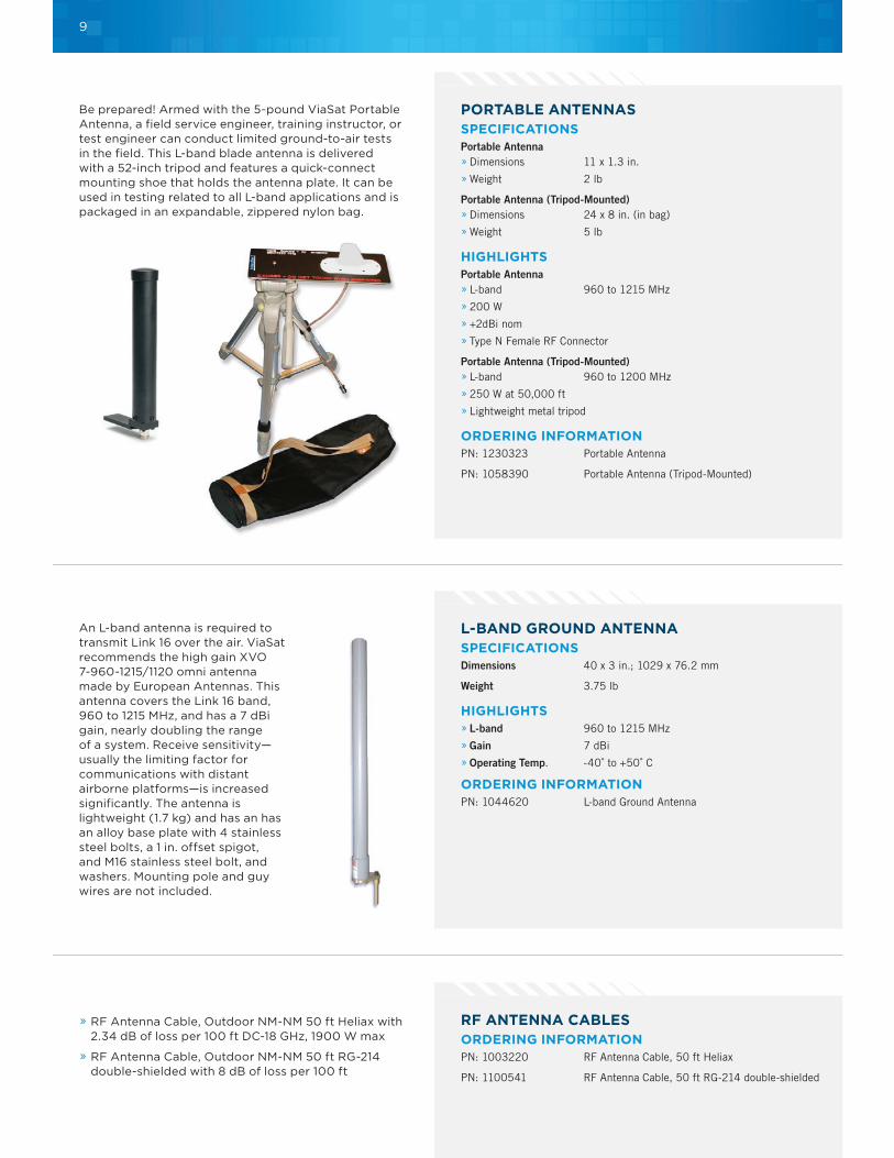
PORTABLE ANTENNASSPECIFICATIONSPortable Antenna » Dimensions 11 x 1.3 in.
» Weight 2 lb
Portable Antenna (Tripod-Mounted) » Dimensions 24 x 8 in. (in bag)
» Weight 5 lb
HIGHLIGHTSPortable Antenna » L-band 960 to 1215 MHz
» 200 W
» +2dBi nom
» Type N Female RF Connector
Portable Antenna (Tripod-Mounted) » L-band 960 to 1200 MHz
» 250 W at 50,000 ft
» Lightweight metal tripod
ORDERING INFORMATIONPN: 1230323 Portable Antenna
PN: 1058390 Portable Antenna (Tripod-Mounted)
Be prepared! Armed with the 5-pound ViaSat Portable Antenna, a field service engineer, training instructor, or test engineer can conduct limited ground-to-air tests in the field. This L-band blade antenna is delivered with a 52-inch tripod and features a quick-connect mounting shoe that holds the antenna plate. It can be used in testing related to all L-band applications and is packaged in an expandable, zippered nylon bag.
9
Support Equipment for MIDS JTRS Terminals
LINK 16 ENVIRONMENT GATEWAY SIMULATOR (LEGS)HIGHLIGHTS » Terminal initialization control
» Terminal status monitoring
» Detailed recording
» MIDS re-programmer
» Scenario generation
» Situation awareness
» Gateway to up to 8 client applications
» Multi-terminal control
SUPPORTED TERMINAL TYPES » MIDS LVT(1) Platform A, B, D, I and Support Port
» MIDS LVT(2) X.25, Plaform J, JREAP-C, and Support Port
» MIDS on Ship (MOS) Platform M and Support Port
» MIDS LVT(3) FDL and Support Port
» Class 2 Navy Shipboard, Navy Airborne, Army 2M, and USAF F-15
» STT Platform J
LEGS-LITE » A low-cost version of the LEGS software that does not include the scenario generation or situation display capabilities is available.
ORDERING INFORMATIONPN: VA-022801-9000 LEGS
PN: VA-022801-9500 LEGS-LITE
LINK 16 FLIGHT-LINE TOOL (LIFT)HIGHLIGHTS » Obtain Terminal Status: IPF Fail, TDMA Rcv/Tx Fail, TDMA Degraded, Thermal Overload, and Sanitization Confirmation
» Initiate Built-In Test (IBIT)
» View SDU alert status
» View position data
» View cockpit ID
» Modify a limited number of settings: Set/Change CCPD, STN, NTR, Time, Tx Mode, Output Power Mode, TACAN Settings, and Voice Channel
» Load an initialization file
» Start net entry
» Participate in a network
» View 12 sec counters
» Observe received RF messages by type
» Exercise TACAN function
» Sanitize terminal for shipment
ORDERING INFORMATIONPN: 1194824 LiFT Handheld Kit
PN: 1043058 Software License and CD
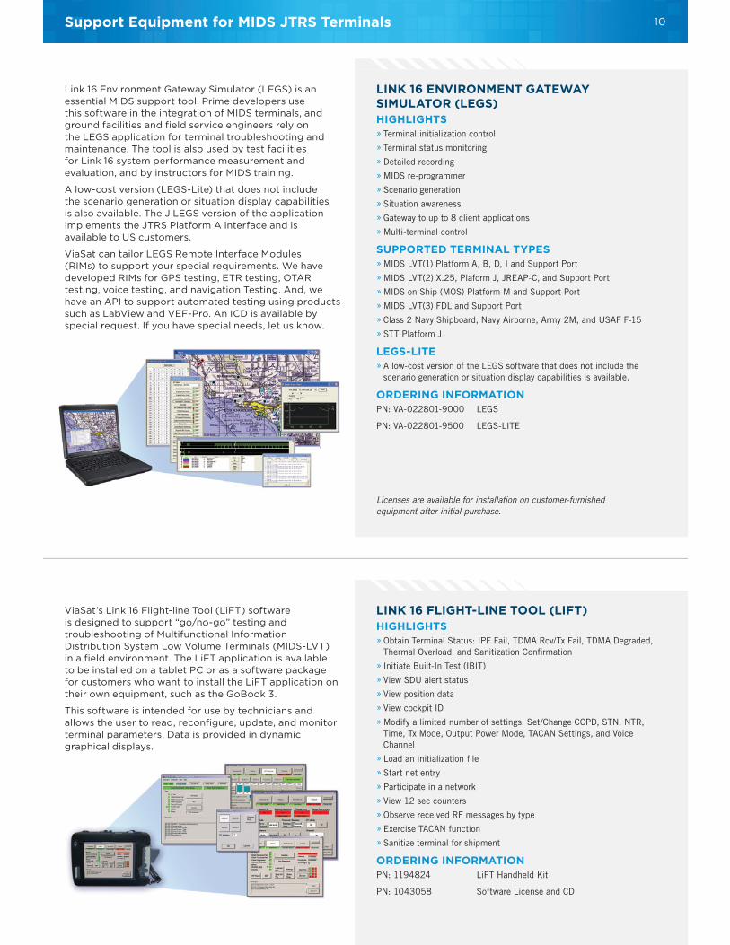
Link 16 Environment Gateway Simulator (LEGS) is an essential MIDS support tool. Prime developers use this software in the integration of MIDS terminals, and ground facilities and field service engineers rely on the LEGS application for terminal troubleshooting and maintenance. The tool is also used by test facilities for Link 16 system performance measurement and evaluation, and by instructors for MIDS training.
A low-cost version (LEGS-Lite) that does not include the scenario generation or situation display capabilities is also available. The J LEGS version of the application implements the JTRS Platform A interface and is available to US customers.
ViaSat can tailor LEGS Remote Interface Modules (RIMs) to support your special requirements. We have developed RIMs for GPS testing, ETR testing, OTAR testing, voice testing, and navigation Testing. And, we have an API to support automated testing using products such as LabView and VEF-Pro. An ICD is available by special request. If you have special needs, let us know.
ViaSat’s Link 16 Flight-line Tool (LiFT) software is designed to support “go/no-go” testing and troubleshooting of Multifunctional Information Distribution System Low Volume Terminals (MIDS-LVT) in a field environment. The LiFT application is available to be installed on a tablet PC or as a software package for customers who want to install the LiFT application on their own equipment, such as the GoBook 3.
This software is intended for use by technicians and allows the user to read, reconfigure, update, and monitor terminal parameters. Data is provided in dynamic graphical displays.
Licenses are available for installation on customer-furnished equipment after initial purchase.
10

Testing Feedback
Hands-on Lab
Classroom Instruction
TDL TECHNICAL SUPPORT AND TRAINING » Each course employs a combination of dialectic lecture and hands-on laboratory.
» The typical percentage breakdown of lecture/lab hours is 40/60.
» Practical lab sessions reinforce all course instruction, providing the student with hands-on experience with MIDS-LVT and LEGS products.
» The lab sessions develop the skill and knowledge of each student for safe and efficient operation of MIDS-LVT and efficient use of LEGS software.
BENEFITS OF ATTENDANCEThe ViaSat MIDS-LVT and/or LEGS training course will provide the following:
» Overview of Link 16
» Overview of MIDS-LVT
» Basic understanding of the LEGS software architecture
» Thorough understanding of LEGS functions and applications
» Knowledge in the safe and efficient operation of MIDS-LVT
» Ability to employ LEGS software to control the MIDS-LVT
» Ability to use LEGS software to easily isolate faults on the MIDS-LVT
ADDITIONAL COURSE INFORMATIONScheduleTraining courses are available for as short as 1 day and as long as 2 weeks (depending on the material to be covered). Class size is normally limited to 12 students.
Contact us for individual pricing information.
LocationThe preferred training location is ViaSat’s Carlsbad facility located at 6155 El Camino Real, Carlsbad, CA 92009
NoteTraining at the customer’s facility requires the provision of terminals and support equipment as customer furnished equipment.
Classroom instruction, materials, and lab procedures are created from testing data and customer feedback.
11

Support Equipment for MIDS JTRS Terminals
COURSE OFFERINGSViaSat offers a variety of training courses related to Link 16 and the operation of the MIDS, MIDS JTRS, and the STT1 terminals. We also offer training on our software products including LEGS, ARMS, and TOES2. Course outlines are available upon request. Tailoring of the standard syllabus to meet specific customer needs is possible—let us know your requirements. The training courses listed below are offered at group rates. We also offer courses at individual rates. Contact ViaSat for further information.
VSAT 101 MIDS Familiarization (Short Course)1-day training course on MIDS-LVT
VSAT 102 LEGS Familiarization (Short Course)1-day training course on ViaSat’s LEGS host
VSAT 103 Link 16 Familiarization (Short Course)2-day training course on the introduction to Link 16
VSAT 104 MIDS and LEGS Familiarization3-day training course covering the use of LEGS and MIDS operation
VSAT 105 MIDS Specifications and Documentation (Short Course) 1-day training course on MIDS ICDs and SSS
VSAT 106 Link 16 Flight-line Tool (LiFT) 2-day training course on ViaSat’s LiFT
VSAT 106A LiFT Training 2-day training course on ViaSat’s LiFT
VSAT 201 Introduction to MIDS/Link 16 for Beginners 5-day training course introducing Link 16 and MIDS (priced individually for entire week)
VSAT 202 MIDS/LEGS: Introduction to Operations and Maintenance 5-day training course on MIDS-LVT, LEGS and the maintenance of the MIDS-LVT
VSAT 204 MIDS/LEGS: Operations and Maintenance for the Field Service Engineer (Available to U.S. Citizens) 7-day training course focusing on the field level maintenance of the MIDS-LVT to include SRU removal
VSAT 205 MIDS JTRS: Operations and Maintenance (Available to MIDS-JTRS Users) 5-day training course focusing on MIDS JTRS operations and maintenance
VSAT 206 ARMS: Link 16 Network Management3-day training course focusing on ARMS Link 16 Network management software
VSAT 207 TOES: Terminal Operational Environment System2-day training course that focuses on the fundamentals, set-up, and operation of TOES in a simulated environment. Course can be tailored to customer requirements
VSAT 208 MIDS Navigation Training3-day training intended for programmers and test analysts responsible for navigation implementation and test verification
VSAT 209 STT Operations 3-day training focusing on user’s Link 16 knowledge and to prepare them to use the STT for dual channel operations
VSAT 210 VLATS Training5-day training focusing on the fundamentals and principles of the VLATS (Available to VLATS Users)
1STT = Small Tactical Terminal2TOES = Terminal Operational Environment Simulator
12
CONTACT
6155 El Camino Real, Carlsbad, CA 92009-1699, USA
U.S. SALES INTERNATIONAL SALES TECHNICAL SUPPORT TEL 760 795 6334 TEL +1 760 476 2675 TEL 866 MIDSLVT EMAIL [email protected] [email protected] EMAIL [email protected] FAX 760 795 1045 WEB www.viasat.com/mids
Copyright © 2009-2016 ViaSat, Inc. All rights reserved. ViaSat and the ViaSat logo are registered trademarks of ViaSat, Inc. All other trademarks mentioned are the sole property of their respective companies. Specifi cations and product availability are subject to change without notice. 030-161128-018