fl exibl e re lia bl e - dyneos ag · precise parallel kinematics hexapod systems with 6 dof and...
TRANSCRIPT
w w w. p i . w s
P R E C I S E
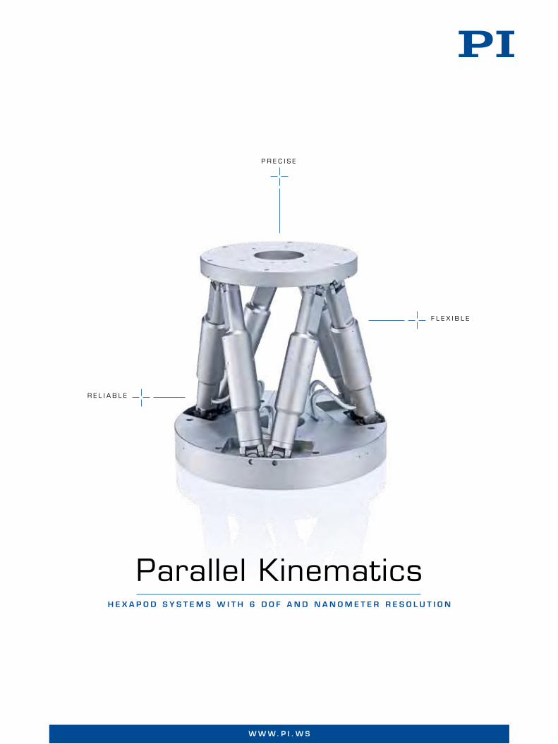
Parallel KinematicsH e x a p o d s y s t e m s w i t H 6 d o F a n d n a n o m e t e r r e s o l u t i o n
f l E x I b l E
R E l I A b l E
2
w w w. p i . w sw w w . p i . w s
H i g H - P r e c i s i o n M o t i o n c o n t r o l i n u P t o s i x A x e s
Hexapods – Parallel-Kinematics Positioning Systems
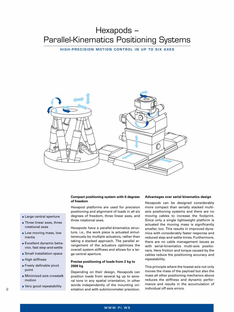
Compact positioning system with 6 degrees of freedom
Hexapod platforms are used for precision positioning and alignment of loads in all six degrees of freedom, three linear axes, and three rotational axes.
Hexapods have a parallel-kinematics struc-ture, i.e., the work piece is actuated simul-taneously by multiple actuators, rather than taking a stacked approach. The parallel ar-rangement of the actuators optimizes the overall system stiffness and allows for a lar-ge central aperture.
Precise positioning of loads from 2 kg to 2000 kg
Depending on their design, Hexapods can position loads from several kg up to seve-ral tons in any spatial orientation, in other words independently of the mounting ori-entation and with submicrometer precision.
Advantages over serial kinematics design
Hexapods can be designed considerably more compact than serially stacked multi-axis positioning systems and there are no moving cables to increase the footprint. Since only a single lightweight platform is actuated the moving mass is significantly smaller, too. This results in improved dyna-mics with considerably faster response and reduced step-and-settle times. Furthermore, there are no cable management issues as with serial-kinematics multi-axis positio-ners. Here friction and torque caused by the cables reduce the positioning accuracy and repeatability.
This principle where the lowest axis not only moves the mass of the payload but also the mass all other positioning mechanics above reduces the stiffness and dynamic perfor-mance and results in the accumulation of individual off-axis errors.
Large central aperture
Three linear axes, three rotational axes
Low moving mass, low inertia
Excellent dynamic beha-vior, fast step-and-settle
Small installation space
High stiffness
Freely definable pivot point
Minimized axis crosstalk motion
Very good repeatability
pi_120265_titel_6achsen.indd 1 16.05.12 16:05
© P
hys
ik In
stru
men
te (
PI)
Gm
bH
& C
o. K
G 2
012.
Su
bje
ct t
o c
han
ge
wit
ho
ut
no
tice
. Lat
est
rele
ases
ava
ilab
le a
t w
ww
.pi.w
s. 1
2/05
/29.
0

3
P I | H e x a P o d sw w w . p i . w s
Selection of the mechanical components
A Hexapod is more than the sum of its indi-vidual parts. All components have to be ca-refully selected and designed with the idea of multi-axis motion in mind. This starts with the use of backlash-free mechanical parts and thermally matched materials. The joints also play a very important part be-cause there are 12 of them and all are in-volved in every move the Hexapod makes. The precision of every strut (actuator) itself is important, too, however it is not enough to equip these actuators with high-resoluti-on sensors and hope the Hexapod system accuracy will be identical to the sensor reso-lution. On the contrary, there are other more important factors.
Motors and drives
PI Hexapods are based on electromechani-cal or piezoelectric drives and differ signifi-cantly from the hydraulic Hexapods known from flight or driving simulators. Depen-ding on the application, direct-drive designs or gear motors are used, rollerscrews or ballscrews, brushless motors and even line-ar motors are employed. PI also makes non-magnetic and EUV compatible Hexapods.
Joints
A number of different joint designs is also available to optimize the Hexapods. If high load capacity and overall stiffness are im-portant universal joints with two ortho-gonally arranged axes, i.e. two degrees of freedom, are the premium choice.
Ball and socket joints offer more degrees of freedom in a relatively simple design. How-ever, the overall stiffness and precision in case of external loads and torque can suffer. A compensating preload is recommended
but requires drives with high output forces such as the NEXLINE® piezo walk motors shown in the figure here.
If the highest precision is required, flexure joints are recommended. They exhibit neit-her friction nor backlash and do not require lubricants. However, they only work over re-latively small travel ranges.
The work space
In addition to linear motion, the Hexapod platform can carry out any combination of tilting and rotation around a freely selectab-le pivot point. Due to the parallel kinematics design, the work space is also not limited by cables movement and cable management systems.
Universal joints of the H-840 Hexapod model
If the stiffness requirements of the total system are lower, a 3-strut design can also be used in which additional degrees of freedom are produced because a passive strut can be moved in two or more axes. Example: In the SpaceFAB the individual struts are driven by one XY translation stage each (figure: PI miCos GmbH)
Ball and socket joints
The Z-axis positioning accuracy of an H-824 Hexapod over 25 mm full travel is in the range of a few micro-meters only, with the repeatability well below ±0.1 µm

4
w w w. p i . w sw w w . P i . w s
Hexapods with passive struts
IInstead of variable, active struts, Hexapo-ds can be designed with passive struts that show constant strut length. In this case the coupling points or joints are usually moved along a linear path. This design is advanta-geous when the drive unit is to be separated from the platform, e.g., outside of vacuum chambers.
Advanced motion control
The individual drives of a Hexapod do not necessarily point in the direction of motion, which is why a powerful controller that can handle the required coordinate transforma-tions in real time is needed.
PI uses advanced digital controllers along with user-friendly software. All motion commands are specifi ed in Cartesian coor-dinates, and all transformations to the indi-vidual actuators take place inside the con-troller.
An important Hexapod property is the free-ly defi nable pivot point. The possibility to rotate around any point in space opens up new applications from fi ber alignment to astronomy.
The entirety of all combinations of translations and rotations that a Hexapod can approach from any given position is called the work space; it is given in reference to the origin of the coordinate system used. The work space can be limited by external factors such as obstacles or the position and size of the load
Constant strut-length Hexapod design. The drive units move the joint position up and down affecting the linear and rotary position of the platform

5
P I | H e x a P o d s
Product Overviewparallel -k inemat ic systems, Hexapods, controllers, soFtware
n Travel ranges to 34 mm / 42°
n Especially compact
n Vacuum-compatible version to 10-6 hPa
page 14H-811 6-Axis Miniature Hexapod
Fast, compact and highly precise
n Travel ranges to 100 mm / 60°
n Vacuum-compatible version to 10-6 hPa
n For high loads
page 8H-850 6-Axis Hexapod
For loads of up to 250 kg
n Travel ranges to 100 mm / 60°
n Cost-effective
page 10H-840 6-Axis Hexapod
High velocity, medium load, affordable
n Travel ranges to 45 mm / 25°
n Vacuum-compatible version to 10-6 hPa
n Cost-effective
page 12H-824 6-Axis Hexapod
Low-profile, precision parallel-kinematic system
n Bidirectional repeatability 0.3 µm
n Min. incremental motion 0.1 µm / 2 µrad
page 16H-206 6-Axis Precision Alignment System
Ideal for fiber alignment
n Travel ranges to 40 mm / 60°
n Especially compact
page 20H-810 6-Axis Miniature Hexapod
High precision in a small package
n Travel ranges to 100 mm / 10°
n Vacuum-compatible version to 10-9 hPa
page 18SF-3000 BS PI miCos SpaceFAB
6-Axis positioning system

6
w w w. p i . w s
n Travel ranges to 400 mm / 40°
n For high loads
n Travel ranges to 100 mm / 6°
n For high loads
n Clear aperture Ø 420 mm
n Long lifetime: 2 million cycles
n Travel range 400 µm coarse, 40 µm fine
n Closed-loop resolution to 2 nm
n Travel ranges 10 mm, 6°
n Non-magnetic
n Nanometer-resolution
page 21
page 22
page 22
page 23
page 23
n Vacuum-compatible version to 10-6 hPa
n For high loads
n Repeatability to 2 µm
page 21M-850KHLH Vacuum-Compatible High-Load Hexapod
Precise positioning of loads of up to 1 ton
M-850KHTH 1000 kg High-Load Hexapod
6 axes, large travel range, accuracy in the micrometer range
M-850KPAH 6-Axis Positioner
Low-profile precision positioning system for large surface loads to 200 kg
M-850KWAH Weather-Resistant Hexapod for Astronomy
Precision 6-axis positioner for outdoor applications
N-510KHFS High-Stiffness Nanopositioning Z Stage with NEXLINE® Piezomotors
High-precision vertical positioning, with capacitive feedback
N-515KNPH Non-Magnetic Piezo Hexapod
6-axis precision positioning system with NEXLINE® piezo stepping drives
n Travel ranges to 1.5 mm / 2°
n Non-magnetic
n Vacuum-compatible version to 10-6 hPa
n Especially compact
page 20P-911KNMV UHV-Compatible Miniature Piezo Hexapod
High-precision positioning even in strong magnetic fields

7
P I | H e x a P o d s
n Optional control of additional motion axes
n Extensive software support
n Rapid start-up
n Universal command set
n Dedicated Hexapod software
n Works under extreme environmental conditions
n Digital motion control-ler for Hexapods with piezo stepping drives
n Optional control of additional motion axes
n Control designs
n Handling systems, tool inspection, medical technology, space telescopes, …
n Manual control unit
n Fiber nanopositioning system
n Extension cable set
page 26
page 28
page 32
page 32
page 33
page 35
n Scalable travel ranges
n For high loads
page 24H-845 Modular, Scalable Hexapod Concept
Faster custom designs for extreme loads
C-887 Controller for Hexapod Positioning Systems
6-D vector motion control, comprehensive functionality
Software from PI
Effective and comfortable solutions
C-843KALM Hexapod Controller for Use at High Altitudes
Signal transmission over long distances
E-712KNHC High-End Digital Motion Controller
For multiaxis systems with piezo step-ping drives and complex control
loops
Application Examples
Accessories
For Hexapod systems
w w w . p i . w s
E f f E c t i v E a n d c o m f o r ta b l E S o l u t i o n S
Motion Control Software from PI
All digital controllers made by PI are accom-panied by a comprehensive software packa-ge. PI supports users as well as program-mers with detailed online help and manuals which ease initiation of the inexperienced but still answer the detailed questions of the professional. Updated software and drivers are always available to PI customers free of charge via the Internet.
PI software covers all aspects of the appli-cation* from the easy start-up to convenient system operation via a graphical interface and quick and comprehensive integration in customer written application programs.
Universal command set simplifies commissioning and programming
PI’s General Command Set (GCS) structure is consistent for all controllers regardless of
their complexity and purpose. GCS with its many preprogrammed functions accelera-tes the orientation phase and the application development process significantly while reducing the chance of errors, because the commands for all supported devices are identical in syntax and function. Further advantages are that different PI controllers can be added and integrated more easily and system upgrades can be introduced with a minimum of programming effort.
Supported operating systems
Windows XP (SP3)
Windows VISTA
Windows 7 32/64 bit
Linux 32/64 bit
NanopositioningS U B - N A N O M E T E R R E S O L U T I O N
MicropositioningL O N G T R A V E L R A N G E S
Parallel KinematicsU P T O 6 D E G R E E S O F F R E E D O M
Drive TechnologyD C , S T E P P E R , P I E Z O , M A G N E T I C
GCSM O T I O N C O N T R O L
Ph
ysik
Inst
rum
ente
(P
I) G
mb
H &
Co
. KG
201
2. S
ub
ject
to
ch
ang
e w
ith
ou
t n
oti
ce. L
ates
t re
leas
es a
vaila
ble
at
ww
w.p
i.ws.
12/
05/2
3.0
* Not every function is available for all controllers. For details, please refer to the corresponding product data sheets.w w w . P i . w s
Application Examples
Patient positioning in radiotherapy
In modern medical technology, a Hexapod can help in radi-ation treatment, for example: the Hexapod makes sure the patient is brought into exactly the right position and orienta-tion. This makes it possible to precisely direct the radiation and mitigate the effect on surrounding tissue (figure: cour-tesy of CIVCO Medical Solutions).
Positioning of telescope reflectors
In the ALMA project (Atacama desert, Chile), up to 64 an-tennas are combined to form a virtual single giant radio telescope. PI M-850k Hexapods are integrated to position the secondary reflectors in the antennas. The M-850K me-chanics and controllers, specially designed for operation in hostile conditions, can position loads of up to 75 kg with sub-micron resolution (figure: © ALMA: ESO/NAOJ/NRAO).
Laboratory technology
The M-850 PI Hexapod here aligns a UHV chamber for crystallographic experiments with high-energy X-rays (figu-re: Beamline I811, MAX-lab, Lund, Sweden / UHV chamber: Dr. J. Alvarez, Universidad Autonoma de Madrid, Spain).
For HAndl ing systeMs, tool insPect ion , Med icAl tecHnology, sPAce telescoPes , …
Notes on specifications for Hexapods, see p. 25

8
w w w. p i . w sH e x a p o d S y S t e m S | w w w . p i . w S
© P
hys
ik In
stru
men
te (
PI)
Gm
bH
& C
o. K
G 2
012.
Su
bje
ct t
o c
han
ge
wit
ho
ut
no
tice
. Lat
est
rele
ases
ava
ilab
le a
t w
ww
.pi.w
s. 1
2/05
/22.
0
6-Axis HexapodFor LoadS oF up to 250 kg
H-850 Load capacity to 250 kg
Repeatability to ±0.2 µm
Travel ranges to 100 mm / 60°
Actuator resolution to 5 nm
MTBF 20,000 h
Reference-class 6-axis positioning systemParallel-kinematic design for six degrees of freedom making it significantly more compact and stiff than serial-kinematic systems, higher dynamic range, no moved cables: Higher reliability, reduced friction. Vacuum-compatible versions to 10-6 hPa are available
Drive variantsH-850.H1x with DC gear motors for heavy loads
H-850.G1x with powerful DC motors for higher velocity. Heavy-duty, ultra-high-resolution bearings for 24/7 applications
Powerful digital controller, open software architectureUser-defined, stable pivot point, software-selectable. Positions commanded in Cartesian coordinates. Macro programming. Open source LabVIEW driver set. Work space simulation software. Virtual Hexapod machine software. Optional: Collision avoidance software (external obstacles).
H-850.xx1 includes C-887.11, 6D vector motion controller plus 2 additional servo axes. Options:
Analog interfaces/photometer cards for visible light (F-206.VVU) or the infrared light range (F-206.iiU)
F-206.NCU fast piezo nano-alignment system for alignment with nanometer precision
H-850.xx2 includes C-887.21 compact 6D vector motion controller
Fields of applicationResearch and industry, standard and vacuum environ-ments. For astronomy, optics positioning, aviation and aerospace

9
P I | H e x a P o d s
Ap
pen
dix
Mic
rop
osi
tio
nin
gN
ano
met
rolo
gy
Hex
apo
ds
Par
alle
l Kin
emat
ics
Nan
op
osi
tio
nin
g &
Pie
zoel
ectr
ics
Lin
ear
Act
uat
ors
&M
oto
rs
H e x a p o d S y S t e m S | w w w . p i . w S
H-850.H1x H-850.G1x Unit Tolerance
for higher loads and holding forces for higher velocity and precision
Active axes X, Y, Z, θX, θY, θZ X, Y, Z, θX, θY, θZ
Motion and positioning
Travel range* X, Y ±50 ±50 mm
Travel range* Z ±25 ±25 mm
Travel range* θX, θY ±15 ±15 °
Travel range* θZ ±30 ±30 °
Single-actuator design resolution 0.005 0.05 µm
Min. incremental motion X, Y 1 1 µm typ.
Min. incremental motion Z 0.5 0.5 µm typ.
Min. incremental motion θX, θY, θZ 5 5 µrad typ.
Backlash X, Y 4 5 µm typ.
Backlash Z 1 1.5 µm typ.
Backlash θX, θY 15 25 µrad typ.
Backlash θZ 30 45 µrad typ.
Repeatability X, Y ±1 ±0.5 µm typ.
Repeatability Z ±0.3 ±0.2 µm typ.
Repeatability θX, θY ±5 ±3 µrad typ.
Repeatability θZ ±9 ±6 µrad typ.
Max. velocity X, Y, Z 0.5 8 mm/s
Max. velocity θX, θY, θZ 6 100 mrad/s
Typ. velocity X, Y, Z 0.3 5 mm/s
Typ. velocity θX, θY, θZ 3 50 mrad/s
Mechanical properties
Stiffness X, Y 7 7 N/µm
Stiffness Z 100 100 N/µm
Load (base plate horizontal / any orientation) 250 / 50 50 / 20 kg max.
Holding force, de-energized 2000 / 500 250 / 85 N max.(base plate horizontal / any orientation)
Motor type DC motor, gearhead DC motor, gearhead
Miscellaneous
Operating temperature range -10 to 50 -10 to 50 °C
Material Aluminum Aluminum
Mass 17 17 kg ±5%
Cable length 3 3 m ±10 mm
Vacuum versions to 10-6 hPa are availab-le under the following ordering number: H-850.xV. Specifi cations for vacuum versions can differ.
Technical data specifi ed at 20±3°C.Ask about custom designs!* The travel ranges of the individual coordinates (X, Y, Z, θX, θY, θZ) are
interdependent. The data for each axis in this table shows its maximum travel, where all other axes are at their zero positions. If the other linear or
rotational coordinates are not zero, the available travel may be less.
H-850, dimensions in mm

10
w w w. p i . w sH e x a p o d S y S t e m S | w w w . p i . w S
6-Axis HexapodHigH Veloc ity, med ium load, affordable
H-840 Load capacity to 30 kg
Travel ranges to 100 mm / 60°
Actuator resolution to 16 nm
Repeatability to ±0.4 µm
MTBF 20,000 h
Velocity to 50 mm/s
Precision-class 6-axis systemParallel-kinematic design for six degrees of freedom making it significantly more compact and stiff than serial-kinematic systems, higher dynamic range, no moved cables: Higher reliability, reduced friction
Drive variantsH-840.G1x with DC gear motorsH-840.D1x with powerful DC motors for higher velocity
Powerful digital controller, open software architectureUser-defined, stable pivot point, software-selectable. Positions commanded in Cartesian coordinates. Macro programming. Open source LabVIEW driver set. Work space simulation software. Virtual Hexapod machine software. Optional: Collision avoidance software (external obstacles).
H-840.xx1 includes C-887.11, 6D vector motion controller plus 2 additional servo axes. Options:
Analog interfaces/photometer cards for visible light (F-206.VVU) or the infrared light range (F-206.iiU)
F-206.NCU fast piezo nano-alignment system for alignment with nanometer precision
H-840.xx2 includes C-887.21 compact 6D vector motion controller
Fields of applicationResearch and industry. For micromanipulation, laser and optics alignment, biotechnology, tool control ©
Ph
ysik
Inst
rum
ente
(P
I) G
mb
H &
Co
. KG
201
2. S
ub
ject
to
ch
ang
e w
ith
ou
t n
oti
ce. L
ates
t re
leas
es a
vaila
ble
at
ww
w.p
i.ws.
12/
05/2
2.0

11
P I | H e x a P o d s
Ap
pen
dix
Mic
rop
osi
tio
nin
gN
ano
met
rolo
gy
Hex
apo
ds
Par
alle
l Kin
emat
ics
Nan
op
osi
tio
nin
g &
Pie
zoel
ectr
ics
Lin
ear
Act
uat
ors
&M
oto
rs
H e x a p o d S y S t e m S | w w w . p i . w S
H-840.G1x H-840.D1x Unit Tolerance
for higher resolution and load for higher velocity
Active axes X, Y, Z, θX, θY, θZ X, Y, Z, θX, θY, θZ
Motion and positioning
Travel range* X, Y ±50 ±50 mm
Travel range* Z ±25 ±25 mm
Travel range* θX, θY ±15 ±15 °
Travel range* θZ ±30 ±30 °
Single-actuator design resolution 0.017 0.5 µm
Min. incremental motion X, Y 1 3 µm typ.
Min. incremental motion Z 0.5 1 µm typ.
Min. incremental motion θX, θY, θZ 5 5 µrad typ.
Backlash X, Y 7 7 µm typ.
Backlash Z 2 2 µm typ.
Backlash θX, θY 30 30 µrad typ.
Backlash θZ 60 60 µrad typ.
Repeatability X, Y ±0.5 ±0.5 µm typ.
Repeatability Z ±0.4 ±0.4 µm typ.
Repeatability θX, θY ±7 ±7 µrad typ.
Repeatability θZ ±12 ±12 µrad typ.
Max. velocity X, Y, Z 2.5 50 mm/s
Max. velocity θX, θY, θZ 30 600 mrad/s
Typ. velocity X, Y, Z 2 30 mm/s
Typ. velocity θX, θY, θZ 20 300 mrad/s
Mechanical properties
Load (base plate horizontal / any orientation) 30 / 10 10 / 3 kg max.
Holding force, de-energized 100 / 25 15 / 5 N max.(base plate horizontal / any orientation)
Motor type DC motor, gearhead DC motor
Miscellaneous
Operating temperature range -10 to 50 -10 to 50 °C
Material Aluminum Aluminum
Mass 12 12 kg ±5%
Cable length 3 3 m ±10 mm
Technical data specifi ed at 20±3°C.Ask about custom designs!* The travel ranges of the individual coordinates (X, Y, Z, θX, θY, θZ) are interdependent. The data for each axis in this table shows its maximum travel, where all other axes are
at their zero positions. If the other linear or rotational coordinates are not zero, the available travel may be less.
H-840, dimensions in mm

12
w w w. p i . w sH e x a p o d S y S t e m S | w w w . p i . w S
© P
hys
ik In
stru
men
te (
PI)
Gm
bH
& C
o. K
G 2
012.
Su
bje
ct t
o c
han
ge
wit
ho
ut
no
tice
. Lat
est
rele
ases
ava
ilab
le a
t w
ww
.pi.w
s. 1
2/05
/22.
0
6-Axis HexapodLow-prof iLe , prec iS ion paraLLeL -K inemat ic SyStem
H-824 Load capacity to 10 kg,
self-locking version
Travel ranges to 45 mm / 25°
Actuator resolution to 7 nm
Min. incremental motion to 0.3 µm
Repeatability to ±0.1 µm / ±2.5 µrad
Velocity up to 25 mm/s
Precision-class 6-axis positioning systemParallel-kinematic design for six degrees of freedom making it significantly more compact and stiff than serial-kinematic systems, higher dynamic range, no moved cables: Higher reliability, reduced friction. Vacuum-compatible versions to 10-6 hPa are available
Low-profile due to folded drive designH-824.G1x with DC gear motorsH-824.D1x with powerful DC motors for higher velocity
Powerful digital controller, open software architectureUser-defined, stable pivot point, software-selectable. Positions commanded in Cartesian coordinates. Macro programming. Open source LabVIEW driver set. Work space simulation software. Virtual Hexapod machine software. Optional: Collision avoidance software (external obstacles).
H-824.xx1 includes C-887.11, 6D vector motion controller plus 2 additional servo axes. Options:
Analog interfaces/photometer cards for visible light (F-206.VVU) or the infrared light range (F-206.iiU)
F-206.NCU fast piezo nano-alignment system for alignment with nanometer precision
H-824.xx2 includes C-887.21 compact 6D vector motion controller
Fields of applicationResearch and industry, standard and vacuum environments. For micromanipulation, laser and optics alignment, biotechnology, tool control

13
P I | H e x a P o d s
Ap
pen
dix
Mic
rop
osi
tio
nin
gN
ano
met
rolo
gy
Hex
apo
ds
Par
alle
l Kin
emat
ics
Nan
op
osi
tio
nin
g &
Pie
zoel
ectr
ics
Lin
ear
Act
uat
ors
&M
oto
rs
H e x a p o d S y S t e m S | w w w . p i . w S
H-824.G1x H-824.D1x Unit Tolerance
for higher resolution and load for higher velocity
Active axes X, Y, Z, θX, θY, θZ X, Y, Z, θX, θY, θZ
Motion and positioning
Travel range* X, Y ±22.5 ±22.5 mm
Travel range* Z ±12.5 ±12.5 mm
Travel range* θX, θY ±7.5 ±7.5 °
Travel range* θZ ±12.5 ±12.5 °
Single-actuator design resolution 0.007 0.5 µm
Min. incremental motion X, Y, Z 0.3 1 µm typ.
Min. incremental motion θX, θY, θZ 3.5 12 µrad typ.
Backlash X, Y 3 3 µm typ.
Backlash Z 1 1 µm typ.
Backlash θX, θY 20 20 µrad typ.
Backlash θZ 25 25 µrad typ.
Repeatability X, Y ±0.5 ±0.5 µm typ.
Repeatability Z ±0.1 ±0.1 µm typ.
Repeatability θX, θY ±2 ±2 µrad typ.
Repeatability θZ ±2.5 ±2.5 µrad typ.
Max. velocity X, Y, Z 1 25 mm/s
Max. velocity θX, θY, θZ 11 270 mrad/s
Typ. velocity X, Y, Z 0.5 10 mm/s
Typ. velocity θX, θY, θZ 5.5 55 mrad/s
Mechanical properties
Stiffness X, Y 1.7 1.7 N/µm
Stiffness Z 7 7 N/µm
Load (base plate horizontal / any orientation) 10 / 5 5 / 2.5 kg max.
Holding force, de-energized 100 / 50 15 / 5 N max.(base plate horizontal / any orientation)
Motor type DC motor, gearhead DC motor
Miscellaneous
Operating temperature range -10 to 50 -10 to 50 °C
Material Aluminum Aluminum
Mass 8 8 kg ±5%
Cable length 3 3 m ±10 mm
Vacuum versions to 10-6 hPa are availab-le under the following ordering number: H-824.xVx. Specifi cations for vacuum versions can differ.
Technical data specifi ed at 20±3°C.Ask about custom designs!* The travel ranges of the individual coordinates (X, Y, Z, θX, θY, θZ) are
interdependent. The data for each axis in this table shows its maximum travel, where all other axes are at their zero positions. If the other linear or
rotational coordinates are not zero, the available travel may be less.
H-824, dimensions in mm

14
w w w. p i . w sH e x a p o d S y S t e m S | w w w . p i . w S
6-Axis Miniature HexapodFaSt, CompaCt and H igHly preC iSe
H-811 Smallest Hexapod with
vacuum option
Travel ranges to 34 mm / 42°
Load capacity to 5 kg
Actuator resolution 40 nm
Min. incremental motion to 0.2 µm
Repeatability to ±0.1 µm
Includes integrated scan algorithms for fiber optic alignment
Reference-class 6-axis positioning systemParallel-kinematic design for six degrees of freedom making it significantly more compact and stiff than serial-kinematic systems, higher dynamic range, no moved cables: Higher reliability, reduced friction. Vacuum-compatible version to 10-6 hPa available
Direct drive with brushless DC motors (BLDC) and long-life ball screwsHigh precision, velocity and lifetime
Powerful digital controller, open software architectureUser-defined, stable pivot point, software-selectable. Positions commanded in Cartesian coordinates. Macro programming. Open source LabVIEW driver set. Work space simulation software. Virtual Hexapod machine software. Optional: Collision avoidance software (external obstacles).
H-811.xx1 includes C-887.11, 6D vector motion controller plus 2 additional servo axes. Options:
Analog interfaces/photometer cards for visible light (F-206.VVU) or the infrared light range (F-206.iiU)
F-206.NCU fast piezo nano-alignment system for alignment with nanometer precision
H-811.xx2 includes C-887.21 compact 6D vector motion controller
Fields of applicationResearch and industry, standard and vacuum environments. For micromanipulation, laser and optics alignment, biotechnology, tool control ©
Ph
ysik
Inst
rum
ente
(P
I) G
mb
H &
Co
. KG
201
2. S
ub
ject
to
ch
ang
e w
ith
ou
t n
oti
ce. L
ates
t re
leas
es a
vaila
ble
at
ww
w.p
i.ws.
12/
05/2
2.0

15
P I | H e x a P o d s
Ap
pen
dix
Mic
rop
osi
tio
nin
gN
ano
met
rolo
gy
Hex
apo
ds
Par
alle
l Kin
emat
ics
Nan
op
osi
tio
nin
g &
Pie
zoel
ectr
ics
Lin
ear
Act
uat
ors
&M
oto
rs
H e x a p o d S y S t e m S | w w w . p i . w S
H-811.D1x Unit Tolerance
Active axes X, Y, Z, θX, θY, θZ
Motion and positioning
Travel range* X, Y, Z ±17, ±16, ±6.5 mm
Travel range* θX, θY, θZ ±10, ±10, ±21 °
Single-actuator design resolution 40 nm
Min. incremental motion X, Y 0.5 µm typ.
Min. incremental motion Z 0.2 µm typ.
Min. incremental motion θX, θY, θZ 3.5 µrad typ.
Backlash X, Y 1 µm typ.
Backlash Z 0.2 µm typ.
Backlash θX, θY 10 µrad typ.
Backlash θZ 15 µrad typ.
Repeatability X, Y ±0.3 µm typ.
Repeatability Z ±0.1 µm typ.
Repeatability θX, θY ±4 µrad typ.
Repeatability θZ ±8 µrad typ.
Max. velocity X, Y, Z 10 mm/s
Max. velocity θX, θY, θZ 250 mrad/s
Typ. velocity X, Y, Z 5 mm/s
Typ. velocity θX, θY, θZ 120 mrad/s
Mechanical properties
Stiffness X, Y 0.2 N/µm
Stiffness Z 3.6 N/µm
Load (base plate horizontal / any orientation) 5 / 2.5 kg max.
Holding force, de-energized (base plate horizontal / any orientation) 15 / 2.5 N max.
Motor type Brushless DC motor
Miscellaneous
Operating temperature range 0 to 50 °C
Material Stainless steel, aluminum
Mass 2.2 kg ±5%
Cable length 2 m ±10 mm
Vacuum versions to 10-6 hPa are available under the following ordering number: H-811.DVx. Specifi cations for vacuum versions can differ.Technical data specifi ed at 20±3°C.Ask about custom designs!* The travel ranges of the individual coordinates (X, Y, Z, θX, θY, θZ) are interdependent. The data for each axis in this table shows its maximum travel, where all other axes are
at their zero positions. If the other linear or rotational coordinates are not zero, the available travel may be less.
H-811, dimensions in mm
16
w w w. p i . w sH e x a p o d S y S t e m S | w w w . p i . w S
6-Axis Precision Alignment Systemideal for f iber al ignment
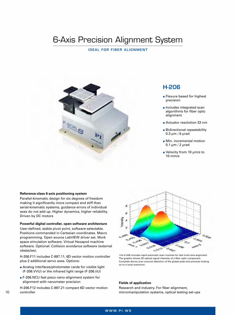
H-206 Flexure based for highest
precision
Includes integrated scan algorithms for fiber optic alignment
Actuator resolution 33 nm
Bidirectional repeatability 0.3 µm / 6 µrad
Min. incremental motion 0.1 µm / 2 µrad
Velocity from 10 µm/s to 10 mm/s
Reference-class 6-axis positioning systemParallel-kinematic design for six degrees of freedom making it significantly more compact and stiff than serial-kinematic systems, guidance errors of individual axes do not add up. Higher dynamics, higher reliability.Driven by DC motors
Powerful digital controller, open software architectureUser-defined, stable pivot point, software-selectable. Positions commanded in Cartesian coordinates. Macro programming. Open source LabVIEW driver set. Work space simulation software. Virtual Hexapod machine software. Optional: Collision avoidance software (external obstacles).
H-206.F11 includes C-887.11, 6D vector motion controller plus 2 additional servo axes. Options:
Analog interfaces/photometer cards for visible light (F-206.VVU) or the infrared light range (F-206.iiU)
F-206.NCU fast piezo nano-alignment system for alignment with nanometer precision
H-206.F12 includes C-887.21 compact 6D vector motion controller
Fields of applicationResearch and industry. For fiber alignment, micromanipulation systems, optical testing set-ups
The H-206 includes rapid automatic scan routines for fast multi-axis alignment. The graphic shows 2D optical signal intensity of a fiber optic component. Complete device scan ensures detection of the global peak and prevents locking on to a local maximum
© P
hys
ik In
stru
men
te (
PI)
Gm
bH
& C
o. K
G 2
012.
Än
der
un
gen
vo
rbeh
alte
n. A
ktu
elle
Rev
isio
n u
nte
r w
ww
.pi.w
s. 1
2/05
/24.
0

17
P I | H e x a P o d s
Ap
pen
dix
Mic
rop
osi
tio
nin
gN
ano
met
rolo
gy
Hex
apo
ds
Par
alle
l Kin
emat
ics
Nan
op
osi
tio
nin
g &
Pie
zoel
ectr
ics
Lin
ear
Act
uat
ors
&M
oto
rs
H e x a p o d S y S t e m S | w w w . p i . w S
H-206.F1x Unit Tolerance
Active axes X, Y, Z, θX, θY, θZ
Motion and positioning
Travel range* X -8 to 5.7 mm
Travel range* Y ±5.7 mm
Travel range* Z ±6.7 mm
Travel range* θX ±5.7 °
Travel range* θY ±6.6 °
Travel range* θZ ±5.5 °
Single-actuator design resolution 33 nm
Min. incremental motion X, Y, Z 0.1 µm typ.
Min. incremental motion θX, θY, θZ 2 µrad (0.4“) typ.
Bidirectional repeatability X, Y, Z 0.3 µm typ.
Bidirectional repeatability θX, θY, θZ 6 µrad typ.
Max. velocity X, Y, Z 10 mm/s
Load (baseplate horizontal) 1.5 kg max.
Miscellaneous
Operating temperature range 5 to 35 °C
Material Aluminum
Mass 5.8 kg ±5%
Cable length 3 m ±10 mm
Technical data specifi ed at 20±3°C.Ask about custom designs!* The travel ranges of the individual coordinates (X, Y, Z, θX, θY, θZ) are interdependent. The data for each axis in this table shows its maximum travel, where all other axes
are at their zero positions. If the other linear or rotational coordinates are not zero, the available travel may be less.
The H-206 Hexapod shows extremely good repeatability of minute steps, in the above graph: 0.5 µm steps with a load of 1 kg in X directionH-206.S, dimensions in mm

18
w w w. p i . w sw w w . p i . w s
6 - A x i s P o s i t i o n i n g s y s t e m
PI miCos SpaceFAB
PI miCos reference-class 6-axis positioning system
Parallel-kinematic design for six degrees of freedom making it significantly more com-pact and stiffer than serial-kinematic sys-tems, higher dynamics. Vacuum-compatible versions to 10-6 hPa are available on request
Special controller and customer-friendly software
Positions commands in Cartesian coordi-nates. Simulation software calculates the work space. Macro functionality
Fields of application
Industry and research, vacuum environ-ments. For automated alignment of optical components, automation, biomedicine and biogenetics
Low-profile, compact system
Linear travel ranges to 50 x 100 x 12.7 mm, rotations to 10°
Load capacity to 3 kg
Vacuum versions available
Virtual pivot point
User-friendly software, controller, and amplifier included
Ask about custom designs and complete solutions!
© P
hys
ik In
stru
men
te (
PI)
Gm
bH
& C
o. K
G 2
012.
Su
bje
ct t
o c
han
ge
wit
ho
ut
no
tice
. Lat
est
rele
ases
ava
ilab
le a
t w
ww
.pi.w
s. 1
2/06
/25.
0
SpaceFAB SF-3000 BS
Active axes X, Y, Z, θX, θY, θZ
Motion and positioning
Travel range* X 50 mm
Travel range* Y 100 mm
Travel range* Z 12.7 mm
Travel range* θX, θY, θZ 10°
Min. incremental motion X, Y, Z, unloaded 0.2 µm
Min. incremental motion θX, θY, θZ unloaded 0.0005°
Bidirectional repeatability X, Y, Z ± 0.5 µm
Bidirectional repeatability θX, θY, θZ 20 µrad
Max. velocity X, Y, Z 30 mm/s
Typ. velocity X, Y, Z 10 µm/s to 10 mm/s
Max. velocity θX, θY, θZ 10°/s
Mechanical properties
Max. load (baseplate horizontal) 3 kg
Miscellaneous
Material Stainless steel, aluminum black anodized
Mass 24 kg
* The travel ranges of the individual coordinates ( X, Y, Z, θX, θY, θZ) are interdependent. The data for each axis in this table shows its maximum travel, where all other axes are at their zero positions. If the other linear or rotational coordinates are not zero, the available travel may be less.
Further data, see www.pimicos.com

19
P I | H e x a P o d sw w w . p i . w s
Customer-specific manufacturing
SpaceFAB 6-axis positioning systems can be easily adapted to individual customer requirements. Vacuum-compatible versions as well as a scaling of the load capacity or dimensions are possible.
What they all have in common is the control with a highly developed digital controller. The commands are comfortably given in Cartesian coordinates, the pivot point for rotary motions can be placed arbitrarily by the customer. In „Contouring Mode“ trajectories can be predefined, and the SpaceFAB can move along them.
A simulation program, the SpaceFAB Simulator, shows possible travel ranges in a specific application-related environment.
Application example: Automated sandwich assembly in six degrees of freedom
A special challenge for the use of a Space-Fab: A fully automated sandwich assembly integrated in the production process for
assembly line production under vacuum conditions with 10-6 mbar.
A carrier is fitted with a precision foil and a rear-side counter holder, thereby the 1 m2 foil has to be positioned with an accuracy of ± 20 µm in relation to the carrier. Since the position of the carrier varies, the assembly process, which must not take longer than 10 seconds, can only be done with a posi- tioning system with six degrees of freedom. For the travels of 50 mm in the direction of assembly and 20 mm perpendicular to it, the SpaceFAB is ideal due to its low height.
The system developed for this application can move loads of 100 kg with low vibra- tion, fast, and very precisely. The key to this is an ingenious combination of the mecha-nical system, the spindle pitch, and a high encoder resolution. This all-in-one solution from PI miCos includes the software for controlling the sandwich assembly, the integration of the sensor measurements as well as the cameras for monitoring the gripper magnets.
Demonstration of a SpaceFAB in a vacuum chamber

20
w w w. p i . w sH E X A P O D S Y S T E M S | W W W . P I . W S
UHV-Compatible Miniature Piezo HexapodH I G H - P R E C I S I O N P O S I T I O N I N G E V E N I N S T R O N G M A G N E T I C F I E L D S
� Ultra-compact
� UHV-compatible to 10-9 hPa
� Non-magnetic
� Ultra-high precision fl exure joints
� Load capacity to 1.5 kg
� Travel ranges to 1.5 mm, to 2°
� With NEXLINE® piezo stepping drives
Customized Travel ranges Max. load Sensor resolution Dimensions
solution
P-911KNMV X, Y, Z: 1.5 mm 1.5 kg 0.1 µm Øexternal: 100 mmminiature θX, θY, θZ: 2° Height 90 mmHexapod
P-911K
The space-saving parallel-kinematic design allows for the low overall height of less than 90 mm and a diameter of only 100 mm. NEXLINE® piezo stepping motor drives and integrated incremental sensors ensure a position resolution down to 0.1 µm in the linear axes
Ap
pen
dix
Mic
rop
osi
tio
nin
g N
ano
met
rolo
gy
Hex
apo
ds
Par
alle
l Kin
emat
ics
Nan
op
osi
tio
nin
g &
Pie
zoel
ectr
ics
Lin
ear
Act
uat
ors
&
Mo
tors
© P
hys
ik In
stru
men
te (
PI)
Gm
bH
& C
o. K
G 2
012.
Su
bje
ct t
o c
han
ge
wit
ho
ut
no
tice
. Lat
est
rele
ases
ava
ilab
le a
t w
ww
.pi.w
s. 1
2/06
/25.
0
6-Axis Miniature HexapodH I G H P R E C I S I O N I N A S M A L L PA C K A G E
� Most compact standard Hexa-pod in the PI portfolio
� Travel ranges to 40 mm / 60°
� Load capacity to 5 kg
� Actuator resolution 40 nm
� Min. incremental motion to 0.5 µm
� Repeatability to ±0.1 µm
H-810
Despite its compact dimensions, the H-810 offers a large a travel range of up to 40 mm. Brushless DC motors and ball screws provide for high precision and long lifetime
Max. Travel Rotation Max. Dimensions load ranges ranges velocity
H-810 5 kg X, Y: ±20 mm θX, θY: ±10° 2.5 mm/s Ø external: 100 mmminiature Z: ±6.5 mm θZ: ±30° Height: 118 mm Hexapod

21
P I | H e x a P o d sH E X A P O D S Y S T E M S | W W W . P I . W S
Vacuum-Compatible High-Load Hexapod
1000 kg High-Load Hexapod
P R E C I S E P O S I T I O N I N G O F L O A D S O F U P T O 1 T O N
6 A X E S , L A R G E T R AV E L R A N G E , A C C U R A C Y I N T H E M I C R O M E T E R R A N G E
� Vacuum compatible to 10-6 hPa
� Load capacity to 1000 kg
� Six Degrees of Freedom
� Six Degrees of Freedom
� Load capacity to 1000 kg in any orientation
� Travel ranges to 400 mm / 40°
� Repeatability to 2 µm
� Drive: brushless motors with brake
� Resolution to 0.8 µm / 0.5 µrad
� Sophisticated controller using vector algorithms
Customized Travel ranges Rotation Max. Dimensionssolution ranges velocity
M-850KHLH X, Y, Z: ±12 mm θX, θY: ±3° X, Y, Z: 0.5 mm/s Ø external: 1 mVacuum θZ: ±4° Height: 0.5 mCompatible HighLoad Hexapod
M-850K
M-850K
Experiments on accelerator rings are often carried out under vacuum con-ditions. This vacuum-compatible Hexapod is well-suited for high precision positioning of loads of up to 1 ton (H-840 standard Hexapod (30 kg load) for size comparison)
Brushless DC servo motors with brakes in this custom parallel-kinematic Hexapod positioning system allow loads of up to one ton to be positioned in any orientation with micrometer accuracy over ranges up to 400 mm
Customized Travel ranges Max. Max. Unidir. Dimensionssolution load velocity repeatability
M-850KHTH X, Y: ±200 mm 1000 kg 1 mm/s X, Y, Z: ±1 µm Base platform:High-Load Z: ±100 mm θX, θY, θZ: ±3 µrad Ø 900 mmHexapod θX, θY: ±20° Upper platform: θZ: ±5° Ø 800 mm Height: 714 mm Aperture: Ø 500 mm
Ap
pen
dix
Mic
rop
osi
tio
nin
g N
ano
met
rolo
gy
Hex
apo
ds
Par
alle
l Kin
emat
ics
Nan
op
osi
tio
nin
g &
Pie
zoel
ectr
ics
Lin
ear
Act
uat
ors
&
Mo
tors
© P
hys
ik In
stru
men
te (
PI)
Gm
bH
& C
o. K
G 2
012.
Su
bje
ct t
o c
han
ge
wit
ho
ut
no
tice
. Lat
est
rele
ases
ava
ilab
le a
t w
ww
.pi.w
s. 1
2/06
/19.
0

22
w w w. p i . w sH E X A P O D S Y S T E M S | W W W . P I . W S
6-Axis Positioner
Weather-Resistant Hexapod for Astronomy
L O W - P R O F I L E P R E C I S I O N P O S I T I O N I N G S Y S T E M F O R L A R G E S U R FA C E L O A D S T O 2 0 0 K G
P R E C I S I O N 6 - A X I S P O S I T I O N E R F O R O U T D O O R A P P L I C AT I O N S
� Six Degrees of Freedom
� Low-profi le design due to parallel kinematics
� Encoder resolution 0.1 µm
� Repeatability 0.3 mm in 6-D space
� Integrated brakes and additional safety switches
� Unidirectional repeatability 5 µm
� Load capacity to 75 kg
� Clear aperture Ø 420 mm
� Long lifetime: 2 million cycles
� No moving cables for improved reliability, reduced friction
� High velocity to 16 mm/s
� Cartesian coordinate control with virtualized pivot point
� Drive: brushless motors
� Corresponds to protection class IP 64
� Corrosion protection
M-850K
M-850K
Hexapod design for precise orientation of large surface loads, e. g. of inspection and assembly systems in LCD production or the positioning of patients in medical engineering
The M-850KWAH custom Hexapod for astronomy applications is protected by rubber boots and and suitable materials. The special mechanical design as well as a non-standard controller make it particularly well-suited for telescope applications in the highlands of Chile, where it is operated out-doors at elevations up to 5,000 m above sea level
Customized solution Travel ranges Max. load Mass Dimensions
M-850KWAH X: ±10 mm 75 kg 46 kg Ø external: 580 mmWeather-Resistant Y: ±11 mm Height: 357 mmfor Astronomy Z: ±16 mm
Customized Travel ranges Min. incremental Max. load Mass Dimensions solution motion
M-850KPAH X, Y: ±50 mm X, Y, Z: 0.1 mm Static: 800 kg 70 kg 1200 × 530 xPositioning Z: ±25 mm θX, θY, θZ: 0.8 mrad Dynamic: 200 kg 184 mmSystem θX, θY, θZ: ±3°
Ap
pen
dix
Mic
rop
osi
tio
nin
g N
ano
met
rolo
gy
Hex
apo
ds
Par
alle
l Kin
emat
ics
Nan
op
osi
tio
nin
g &
Pie
zoel
ectr
ics
Lin
ear
Act
uat
ors
&
Mo
tors
© P
hys
ik In
stru
men
te (
PI)
Gm
bH
& C
o. K
G 2
012.
Su
bje
ct t
o c
han
ge
wit
ho
ut
no
tice
. Lat
est
rele
ases
ava
ilab
le a
t w
ww
.pi.w
s. 1
2/06
/25.
0
23
P I | H e x a P o d sH E X A P O D S Y S T E M S | W W W . P I . W S
High-Stiffness Nanopositioning Z Stage with NEXLINE® Piezomotors
Non-Magnetic Piezo Hexapod
H I G H - P R E C I S I O N V E R T I C A L P O S I T I O N I N G , W I T H C A PA C I T I V E F E E D B A C K
6 - A X I S P R E C I S I O N P O S I T I O N I N G S Y S T E M W I T H N E X L I N E ® P I E Z O S T E P P I N G D R I V E S
� Closed-loop resolution to 2 nm
� Self-locking,no heat generation at rest
� Hybrid piezo drive combines high stiffness, long travel and very fast response
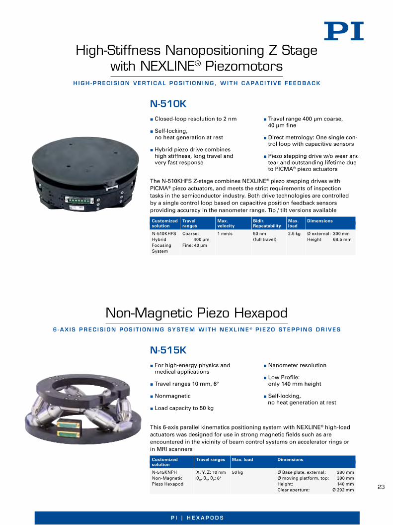
� For high-energy physics and medical applications
� Travel ranges 10 mm, 6°
� Nonmagnetic
� Load capacity to 50 kg
� Travel range 400 µm coarse, 40 µm fi ne
� Direct metrology: One single con-trol loop with capacitive sensors
� Piezo stepping drive w/o wear and tear and outstanding lifetime due to PICMA® piezo actuators
� Nanometer resolution
� Low Profi le: only 140 mm height
� Self-locking, no heat generation at rest
N-510K
N-515K
The N-510KHFS Z-stage combines NEXLINE® piezo stepping drives with PICMA® piezo actuators, and meets the strict requirements of inspection tasks in the semiconductor industry. Both drive technologies are controlled by a single control loop based on capacitive position feedback sensors providing accuracy in the nanometer range. Tip / tilt versions available
This 6-axis parallel kinematics positioning system with NEXLINE® high-load actuators was designed for use in strong magnetic fi elds such as are encountered in the vicinity of beam control systems on accelerator rings or in MRI scanners
Customized Travel ranges Max. load Dimensionssolution
N-515KNPH X, Y, Z: 10 mm 50 kg Ø Base plate, external: 380 mmNon-Magnetic θX, θY, θZ: 6° Ø moving platform, top: 300 mmPiezo Hexapod Height: 140 mm Clear aperture: Ø 202 mm
Customized Travel Max. Bidir. Max. Dimensionssolution ranges velocity Repeatability load
N-510KHFS Coarse: 1 mm/s 50 nm 2.5 kg Ø external: 300 mmHybrid 400 µm (full travel) Height 68.5 mmFocusing Fine: 40 µmSystem
Ap
pen
dix
Mic
rop
osi
tio
nin
g N
ano
met
rolo
gy
Hex
apo
ds
Par
alle
l Kin
emat
ics
Nan
op
osi
tio
nin
g &
Pie
zoel
ectr
ics
Lin
ear
Act
uat
ors
&
Mo
tors
© P
hys
ik In
stru
men
te (
PI)
Gm
bH
& C
o. K
G 2
012.
Su
bje
ct t
o c
han
ge
wit
ho
ut
no
tice
. Lat
est
rele
ases
ava
ilab
le a
t w
ww
.pi.w
s. 1
2/06
/25.
0

24
w w w. p i . w s
Ap
pen
dix
Mic
rop
osi
tio
nin
gN
ano
met
rolo
gy
Hex
apo
ds
Par
alle
l Kin
emat
ics
Nan
op
osi
tio
nin
g &
Pie
zoel
ectr
ics
Lin
ear
Act
uat
ors
&M
oto
rs
H E X A P O D S Y S T E M S | W W W . P I . W S
Modular, Scalable Hexapod ConceptFASTER CUSTOM DES IGNS FOR EXTREME LOADS
� Scalable travel ranges and angles
� Loads scalable to 400 kg in any orientation, horizontally to 1000 kg
� High precision, bidirec-tional repeatability of around 5 µm
� Velocity to 20 mm/s
� Brushless DC motors with brakes
� Sophisticated controller using vector algorithms, virtual pivot point
� Extensive software support
Precision positioning of heavy loads in six degrees of freedom can be achieved with a high degree of fl exibility by parallel-kine-matic structures. The workpiece is actuated simultaneously by multiple actuators, rather than taking a stacked approach. The parallel arrangement of the actuators optimizes the total stiffness, dynamics and allows for a large central aperture.
Custom high-load positioning systems of-ten need to be completely integrated, i.e., the payload acts as the platform to which the 6 actuators need to be attached.
Starting with six identical single struts, PI has developed a concept for an adapted ki-nematic system that meets a wide variety of requirements. A set of different modules for motors, drives, and joints supports the design process and saves time as well as in-vestment costs. The modular design allows
special requirements to be implemented and integrated in the customer‘s application much faster.
The aim is to react to customer requests as quickly as possible and to adapt the positio-ning system according to the individual task at hand.
Powerful digital controller, open software architectureUser-defi ned, stable pivot point, software-selectable. Positions commanded in Cartesi-an coordinates. Macro programming. Open source LabVIEW driver set. Work space si-mulation software. Optional: Control of two additional motorized axes.
© P
hys
ik In
stru
men
te (
PI)
Gm
bH
& C
o. K
G 2
012.
Su
bje
ct t
o c
han
ge
wit
ho
ut
no
tice
. Lat
est
rele
ases
ava
ilab
le a
t w
ww
.pi.w
s. 1
2/05
/21.
0

P I | H e x a P o d s
25
Notes on Specifications for Hexapodsm o t i o n a n d p o s i t i o n i n g
Typ. velocity
Recommended value for continuous ope-ration; also referred to as average or con-tinuous velocity. This value depends on the application.
Mechanical propertiesStiffness
Typical tolerance: ±20%
Max. load
Load limit, load at center of stage, positio-ning system in closed-loop operation. Higher loads will reduce the possible travel ranges and may also reduce the lifetime. Data for vacuum versions can differ.
Max. holding force
The maximum force of the Hexapod when powered down, depending on the orienta- tion of the base plate.
MiscellaneousOperating temperature range
Safe operation, no damage to the drives. All technical data specified in the data sheet refer to room temperature (22°C ±3°C).
Material
Hexapods are made of anodized aluminum or stainless steel. Small amounts of other materials may be used (for bearings, pre-load, coupling, mounting, etc.). For special applications other materials such as invar are possible.
Mass
Typical tolerance: ±5%
Cable length
Typical tolerance: ±10 mm
Travel range
The distance between two limit switches defines the travel range of the individual struts. The maximum travel ranges of the motion axes are interdependent. The stated values indicate the maximum travel of each axis, where all other axes are at their zero positions. If the other linear or rotational co-ordinates are not zero, the available travel may be less.
Design resolution
The theoretical minimum motion that can be made, based on the selection of the me-chanical drive components (spindle pitch, gear ratio, angular motor resolution etc.). Design resolution is usually better than the practical position resolution (minimum incremental motion). For linear encoders, the design describes the resolution of the position feedback sensor system.
Min. incremental motion
The minimum motion that can be repea- tedly executed for a given input is called minimum incremental motion. The values stated are typical measured values.
Backlash
Position error that occurs upon reversing direction due to error in the drivetrain. The values stated are typical measured values. Data for vacuum versions can differ.
Repeatability
Values stated are typical measured values (RMS, 1 sigma) for unidirectional repea- tability.
Max. velocity
This is the short-term peak value for ho-rizontal mounting, with no load, and not intended for continuous operation. Data for vacuum versions can differ.

26
w w w. p i . w s
Controller for Hexapod Positioning Systems6 - D V e c t o r M o t i o n c o n t r o l , c o M p r e h e n s i V e F u n c t i o n a l i t y
c-887 Sophisticated controller
using vector algorithms
Freely programmable, virtual pivot point
Data recorder
Macro program functionality
Stand-alone operation possible and control through TCP/IP and RS-232 interfaces
Extensive software support
Digital controller for 6-axis-parallel kinematicsIncluded in the delivery of all PI standard Hexapod systems C-887.11, 19“ controller, comprises the control for two
additional single axes with servo motors, the functionality can be enhanced with many additional options
C-887.21 compact bench-top controller for a lower system price
Extensive software support
FunctionsReal-time system. Position control using Cartesian coordinates, vectorized motion. Stable, virtual pivot point can be defined freely in the working space. Data recorder for recording operating parameters such as motor control, velocity, position or position error. Macro command language. Stand-alone operation possible with Autostart macro or connection of keyboard and monitor. Optional: Manual control unit
Custom designsCustom designs are available for use at high altitudes, e.g. for astronomical telescope applications. Processing of absolute sensors. Control of motor brakes. Processing of additional (redundant) position sensors for increased safety requirements, e.g. in medical technology
h e x a p o D s y s t e M s | w w w . p i . w s
© P
hys
ik In
stru
men
te (
PI)
Gm
bH
& C
o. K
G 2
012.
Su
bje
ct t
o c
han
ge
wit
ho
ut
no
tice
. Lat
est
rele
ases
ava
ilab
le a
t w
ww
.pi.w
s. 1
2/05
/22.
0
SoftwarePIMikroMove user software. Common command set for all PI positioning systems. Shared libraries for Windows and Linux. Complete set of LabVIEW VI’s. Graphical user interfaces, configuration software and graphically displayed scan routine.Optional: PIVeriMove software for checking a restricted operating space
InterfacesTCP/IP Ethernet can also be used for remote control and service, RS-232. Monitor, mouse and keyboard interface. On request: RS-422 for up to 1.4 km cable length
Possible enhancements for C-887.11 Analog interfaces/photometer cards for visible light
(F-206.VVU) or the infrared light range (F-206.iiU)
F-206.NCU fast piezo nano-alignment system for alignment with nanometer precision
27
P I | H e x a P o d sh e x a p o D s y s t e M s | w w w . p i . w s
Mic
rop
osi
tio
nin
gH
exap
od
s P
aral
lel
Kin
emat
ics
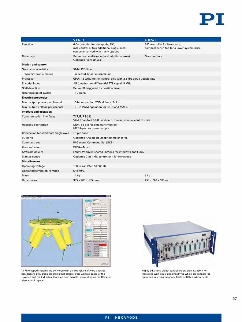
C-887.11 C-887.21
Function 6-D controller for Hexapods, 19“, 6-D controller for Hexapods, incl. control of two additional single axes, compact bench-top for a lower system price can be enhanced with many options
Drive type Servo motors (Hexapod and additional axes) Servo motors Optional: Piezo drives
Motion and control
Servo characteristics 32-bit PID filter
Trajectory profile modes Trapezoid, linear interpolation
Processor CPU: 1.8 GHz, motion control chip with 2.5 kHz servo update rate
Encoder input AB (quadrature) differential TTL signal, 5 MHz
Stall detection Servo off, triggered by position error
Reference point switch TTL signal
Electrical properties
Max. output power per channel 10-bit output for PWM drivers, 24 kHz
Max. output voltage per channel TTL in PWM operation for SIGN and MAGN
Interface and operation
Communication interfaces TCP/IP, RS-232 VGA (monitor), USB (keyboard, mouse, manual control unit)
Hexapod connection MDR, 68-pin for data transmission M12 4-pin. for power supply
Connection for additional single axes 15-pin sub-D –
I/O ports Optional: Analog inputs (photometer cards) –
Command set PI General Command Set (GCS)
User software PIMikroMove
Software drivers LabVIEW driver, shared libraries for Windows and Linux
Manual control Optional: C-887.MC control unit for Hexapods
Miscellaneous
Operating voltage 100 to 240 VAC, 50 / 60 Hz
Operating temperature range 5 to 40°C
Mass 11 kg 5 kg
Dimensions 395 × 483 × 185 mm 255 × 226 × 185 mm
All PI Hexapod systems are delivered with an extensive software package. Included are simulation programs that calculate the working space of the Hexapod and the individual loads on each actuator depending on the Hexapod orientation in space
Highly advanced digital controllers are also available for Hexapods with piezo stepping drives which are suitable for operation in strong magnetic fi elds or UHV environments
Ap
pen
dix
Nan
om
etro
log
y N
ano
po
siti
on
ing
&P
iezo
elec
tric
s Li
nea
r A
ctu
ato
rs &
M
oto
rs

28
w w w. p i . w sw w w . p i . w s
E f f E c t i v E a n d c o m f o r ta b l E S o l u t i o n S
Motion Control Software from PI
All digital controllers made by PI are accom-panied by a comprehensive software packa-ge. PI supports users as well as program-mers with detailed online help and manuals which ease initiation of the inexperienced but still answer the detailed questions of the professional. Updated software and drivers are always available to PI customers free of charge via the Internet.
PI software covers all aspects of the appli-cation* from the easy start-up to convenient system operation via a graphical interface and quick and comprehensive integration in customer written application programs.
Universal command set simplifies commissioning and programming
PI’s General Command Set (GCS) structure is consistent for all controllers regardless of
their complexity and purpose. GCS with its many preprogrammed functions accelera-tes the orientation phase and the application development process significantly while reducing the chance of errors, because the commands for all supported devices are identical in syntax and function. Further advantages are that different PI controllers can be added and integrated more easily and system upgrades can be introduced with a minimum of programming effort.
Supported operating systems
Windows XP (SP3)
Windows VISTA
Windows 7 32/64 bit
Linux 32/64 bit
NanopositioningS U B - N A N O M E T E R R E S O L U T I O N
MicropositioningL O N G T R A V E L R A N G E S
Parallel KinematicsU P T O 6 D E G R E E S O F F R E E D O M
Drive TechnologyD C , S T E P P E R , P I E Z O , M A G N E T I C
GCSM O T I O N C O N T R O L
Ph
ysik
Inst
rum
ente
(P
I) G
mb
H &
Co
. KG
201
2. S
ub
ject
to
ch
ang
e w
ith
ou
t n
oti
ce. L
ates
t re
leas
es a
vaila
ble
at
ww
w.p
i.ws.
12/
05/2
3.0
* Not every function is available for all controllers. For details, please refer to the corresponding product data sheets.

P I | H e x a P o d sw w w . p i . w s
PIMikroMove software ensures rapid start-up
PIMikroMove is PI’s convenient graphi-cal user interface for any type of digital controller and positioning system, regard-less of whether piezoelectric, linear motors, or classical electrical motor drives are used and independent of the configuration and number of axes.
All connected controllers and axes are displayed and controlled consistently with the same graphical interface. Two or more independent axes can be controlled by the position pad using a mouse or joystick; Hexapod six-axis positioning systems are also displayed graphically.
Macro programs simplify repetitive tasks for example in automated processes. The mac-ros are created as GCS command sets that can be executed directly on the controller, e.g., as a start-up macro that allows stand-alone operation; they can also be processed by the host PC.
Scan and align algorithms can record ana-log values, e.g., the output of a power meter as a function of position for later evaluation with external software. They can also auto-matically find the global maximum of, for example, the coupling efficiency of optical devices.
Depending on the specific controller, PIMikroMove supports a number of additi-onal functions. A data recorder can record system parameters and other variables during motion for later analysis.
Optimizing system behavior
When the mechanical properties of a positi-oning system are changed, e.g., by applying a different load, motion control parameters often need to be adapted. PI software provi-des tools for optimization of the system res-ponse and stability. Different parameter sets can be saved for later recall, also accessible from custom application programs.

30
w w w. p i . w sw w w . p i . w s
r a p i d i n t E g r at i o n o f p i p o S i t i o n i n g S y S t E m S a n d c o n t r o l l E r S
Programming
In measuring and control technology and automation engineering, many applications are produced in LabVIEW. PI provides com-plete LabVIEW drivers sets to facilitate pro-gramming. A controller-specific Configurati-on_Setup VI is integrated at the start of the LabVIEW application and includes all system information and initiation steps required for start-up. The application itself is implemented with controller-independent VIs. In case of a controller change or upgrade, it is usually only necessary to exchange the Configurati-on_Setup VI , whereas the application-specific code remains identical due to the consistent GCS command set structure. The driver set includes many specific exemplary programs, e.g., comprehensive scan and align applica-
tions that can be used as template for own programs. Moreover, the open source code of many VIs allows for rapid adaptation to the user needs.
Flexible integration in text-based program-ming languages
The integration of PI positioning systems in text-based programming languages under Microsoft Windows or Linux is simplified by program libraries and exemplary codes.
These libraries support all common pro-gramming languages and all PI positioning systems , allowing the PI GCS command set functions to be integrated seamlessly in ex-ternal programs.
Third-party software packages
Drivers for the PI GCS commands have now been integrated in many third-party soft-ware packages. This allows for the seamless integration of PI positioning systems in soft-ware suites such as MetaMorph, µManager, MATLAB, and ScanImage. Moreover, EPICS and TANGO drivers are available for integra-tion into experiments of large-scale research facilities. The drivers for µManager, MATLAB and a large part of the EPICS drivers are being developed and serviced in-house by PI.
Supported languages and software environments
C, C++, Python, Visual C++, Visual Basic, Delphi
LabVIEW, MATLAB, µManager, EPICS, TANGO, MetaMorph
and all programming environments that support the loading of DLLs

31
P I | H e x a P o d sW W W . p i . W S
Hexapod-Specifi c Software
Due to their parallel kinematic structure, Hexapods necessitate a particularly complex control system. The position coordinates, for example, are given in virtu-al Cartesian axes which are then converted into positioning commands for the indivi-dual actuators by the controller. PI supplies special software that allow the 6-axes posi-tioners to be more convenient in operation and easier to integrate.
Determining the work space
The limits of the work space vary depen-ding on the current position of the Hexa-pod (translation and rotation coordinates) and the current coordinates of the pivot point. A special software tool included with each PI Hexapod calculates these limits and displays them graphically.
Checking the permissible load
As with any multiaxis positioning system, the load limit of the Hexapod varies as a function of a number of factors such as orientation of the Hexapod, size and position of the payload, current position
(translation and rotation coordinates) of the Hexapod platform, and forces and moments acting on the platform.
The Hexapod software package includes a PI simulation tool that calculates all forces and moments and compares them individu-ally against the specifi ed load limits of the corresponding Hexapod mechanics.
Preventing collisions with PIVeriMove
Another proprietary PI simulation software tool enables offl ine graphical confi guration and simulation of the Hexapod motion in the application environment. CAD data of objects can be imported or approximated with simple shapes such as cylinders and cuboids. PIVeriMove then checks restric-tions in the work space. Implemented in the controller fi rmware or the application software, this prevents the Hexapod from approaching positions where the platform, struts, or the mounted load would collide with the surroundings.
Emulation: The Hexapod system as a virtual machine
A virtual machine that can be installed on the customer’s host PC is available to emulate a complete Hexapod systems (mechanics, controller and even periphe-rals). Application programs can then be developed and pre-tested, different load scenarios can be simulated and the work space can be determined before the system arrives, saving signifi cant cost and develop-ment time.
HexaApp: PI Hexapod control via iPhone, iPad or iPod
The Hexapod system can also be controlled wirelessly from mobile Apple iOS devices. A corresponding app enables command control of touchscreen, motion sensors or via a command input window.
The simulation software graphically displays the position and the available work space of the Hexapod model

32
w w w. p i . w sH E X A P O D S Y S T E M S | W W W . P I . W S
© P
hys
ik In
stru
men
te (
PI)
Gm
bH
& C
o. K
G 2
012.
Su
bje
ct t
o c
han
ge
wit
ho
ut
no
tice
. Lat
est
rele
ases
ava
ilab
le a
t w
ww
.pi.w
s. 1
2/06
/25.
0
Hexapod Controller for Use at High Altitudes
High-End Digital Motion Controller
S I G N A L T R A N S M I S S I O N O V E R L O N G D I S TA N C E S
FOR MULT IAX IS SYSTEMS WITH P IEZO STEPPING DRIVES AND COMPLEX CONTROL LOOPS
� Differential transmission of the control signals over long distances
� Control via TCP/IP
� Cooling system and special case
� Sophisticated controller using vector algorithms
� Digital motion controller of the newest generation: up to 50 kHz servo update rate; highly stable 20-bit D/A converter
� Multiaxis coordinate transforma-tion for parallel-kinematic systems (Hexapods)
� Combined control of different positioning technologies feasible
� Freely programmable, virtual pivot point
� Data recorder
� Macro program functionality
� Extensive software support
� Flexible interfaces: Ethernet, USB, RS-232
� Extensive software support
� Optional high-bandwidth analog inputs and outputs
� Modular design for greatest fl exibility in meeting custom requirements
C-843K
E-712KNHC
In the ALMA project (Atacama desert, Chile), up to 64 antennas are combined to form a virtual single giant radio tele-scope. Not only the Hexapod systems from PI, which position the secondary refl ectors in the antennas, must be adapted to the extreme ambient conditions but also the controllers that send their commands sometimes over distances of several hundreds of meters. This robust Hexapod controller is dedicated for use under such conditions and it can, there-fore, easily dissipate heat even in thin mountain air and does not require a fan
The E-712 digital controller system can be confi gured to drive complex piezo positioning systems, for example parallel-kinematic designs with piezo stepping drives. Multiaxis coordinate transformation and coordination of the individual drive sequences required by the piezo-walk motors can be handled by the sophisticated fi rmware. Its modular design allows the controller to be adapted quickly to any requirement such as a variety of feedback sensors and the integration of additional control loops e.g. for active vibration damping
Ap
pen
dix
Mic
rop
osi
tio
nin
g N
ano
met
rolo
gy
Hex
apo
ds
Par
alle
l Kin
emat
ics
Nan
op
osi
tio
nin
g &
Pie
zoel
ectr
ics
Lin
ear
Act
uat
ors
&
Mo
tors

33
P I | H e x a P o d sw w w . p i . w s
F o r U H V - C o m pat i b l e H e x a p o d 6 d - p o s i t i o n e r
Control-Loop Integrates Active Vibration Damping
Positioning systems for UHV environments require special mechanical design features.
One particularly elegant solution is the im-plementation of a parallel-kinematic 6-axis Hexapod with constant leg length, in which only passive parts of the drive system are accommodated inside the vacuum cham-ber. Electrical and electronic parts, such as motors, sensors, wiring or parts in need of
lubrication are situated outside the vacuum chamber. As a result, the space needs within the chamber are very low and the passive hexapod structure inside the chamber is very stiff. Moreover, the vacuum is contami-nated as little as possible and no additional cooling of the drives is needed.
Integrated active vibration damping
A crucial factor for the precision is the de-coupling of low frequency ambient vibra-tions that excite resonances in the mecha-nical system and thus would interfere with the stability and precision of the platform.
For this purpose, the passive struts are equipped with piezo ceramic actuators. A newly developed 6D acceleration sensor feeds vibration back to a closed-loop piezo controller. Digital linearization algorithms for the mechanical and electronic systems and filter functions for the sensor signals further enhance the performance resulting in damping factors in excess of 20 for multi-directional vibrations up to 50 Hz. Lineari-zation algorithms for the mechanical and electronic systems and filter functions for the sensor values then allow undesired vib-rations to be dampened completely. ©
Ph
ysik
Inst
rum
ente
(P
I) G
mb
H &
Co
. KG
201
2. S
ub
ject
to
ch
ang
e w
ith
ou
t n
oti
ce. L
ates
t re
leas
es a
vaila
ble
at
ww
w.p
i.ws.
12/
06/0
4.0
Control design of an E-712 digital controller for active vibration damping
The Hexapod design is based on passive, constant-length struts, where the position of the joint is being shifted by ex-ternal linear actuators. The active and the passive structures are separated by the base plate of the vacuum chamber

34
w w w. p i . w sw w w . P i . w s
Application Examples
Patient positioning in radiotherapy
In modern medical technology, a Hexapod can help in radi-ation treatment, for example: the Hexapod makes sure the patient is brought into exactly the right position and orienta-tion. This makes it possible to precisely direct the radiation and mitigate the effect on surrounding tissue (figure: cour-tesy of CIVCO Medical Solutions).
Positioning of telescope reflectors
In the ALMA project (Atacama desert, Chile), up to 64 an-tennas are combined to form a virtual single giant radio telescope. PI M-850k Hexapods are integrated to position the secondary reflectors in the antennas. The M-850K me-chanics and controllers, specially designed for operation in hostile conditions, can position loads of up to 75 kg with sub-micron resolution (figure: © ALMA: ESO/NAOJ/NRAO).
Laboratory technology
The M-850 PI Hexapod here aligns a UHV chamber for crystallographic experiments with high-energy X-rays (figu-re: Beamline I811, MAX-lab, Lund, Sweden / UHV chamber: Dr. J. Alvarez, Universidad Autonoma de Madrid, Spain).
For HAndl ing systeMs, tool insPect ion , Med icAl tecHnology, sPAce telescoPes , …
Magnetic levitation platform
An unusual example of a Hexapod positioning system: instead of struts, magnetic fields ensure that the platform assumes and maintains the desired position. The relatively large XY motions are accompanied by small angles and Z displacements with accuracy in the nanometer range. The control and operation is performed by a digital controller. In addition to high accelerations and velocities the system is frictionless, vacuum compatible and does not generate any particles.
w w w . P i . w s
Application Examples
Patient positioning in radiotherapy
In modern medical technology, a Hexapod can help in radi-ation treatment, for example: the Hexapod makes sure the patient is brought into exactly the right position and orienta-tion. This makes it possible to precisely direct the radiation and mitigate the effect on surrounding tissue (figure: cour-tesy of CIVCO Medical Solutions).
Positioning of telescope reflectors
In the ALMA project (Atacama desert, Chile), up to 64 an-tennas are combined to form a virtual single giant radio telescope. PI M-850k Hexapods are integrated to position the secondary reflectors in the antennas. The M-850K me-chanics and controllers, specially designed for operation in hostile conditions, can position loads of up to 75 kg with sub-micron resolution (figure: © ALMA: ESO/NAOJ/NRAO).
Laboratory technology
The M-850 PI Hexapod here aligns a UHV chamber for crystallographic experiments with high-energy X-rays (figu-re: Beamline I811, MAX-lab, Lund, Sweden / UHV chamber: Dr. J. Alvarez, Universidad Autonoma de Madrid, Spain).
For HAndl ing systeMs, tool insPect ion , Med icAl tecHnology, sPAce telescoPes , …

35
P I | H e x a P o d s
n Consists of P-611.3SF NanoCube® XYZ nanopositioning system, 100 x 100 x 100 µm, strain gauge sensors with integrated fiber adapter interface and E-760.3S0 NanoCube® piezo controller board, ISA bus
n Optical inputs in the 480 to 1040 nm range
n Analog inputs 0–10 V
n Optical inputs in the 850 to 1680 nm range
n Analog inputs 0–10 V
n For differential signal transmission
n For quick interchange of complete pre-mounted setups
n magnetic kinematically clamped
n Integrates vision systems with PI micro- and nanopositioners
n Includes standard procedures e.g. for gap measurement, autofocus, aligning edges as well as complex alignment routines in six degrees of freedom with an unlimited number of axes of motion
n Mount on a Variety of PI Alignment Systems
n Precision Machined from High-Strength Aluminum/Brass
n Manual control
n Freely definable step size
n Display for position values
C-887.MC Hexapod Control Unit, USB Connector, 3 m Cable
F-206.NCU Rapid 3-Axis Piezo Nanopositioning System
For use in combination with Hexapod systems
F-206.VVU Photometer Card, Visible Range, 2 Channels
F-206.iiU Photometer Card, IR Range, 2 Channels
C-887.A20 Hexapod Cable Set, 20 m
F-206.TMU Additional Mounting Platform
Fits H-206 Hexapods
F-311.LV PIMotion&Vision LabVIEW Driver Set
Supports intelligent automated procedure
F-603 Fiber, Objective and Waveguide Holders
Fits H-206 and P-611 NanoCube®
AccessoriesFor Hexapod systems
For more information, see www.pi.ws
36
w w w. p i . w s
PI (Physik Instrumente) is the leading supplier of piezo-based positioning systems with accuracies in the range of a few nanometers.
The extensive product portfolio is based on a wide range of technologies with electromo-tive or piezoelectric drives for up to six mo-tion axes. Hexapods, nanometer sensors, control electronics as well as software and are supplemented by customized solutions.
All key technologies are developed in-house. This means that every phase from the design right down to the shipment can be controlled: The precision mechanics and the electronics as well as the position sensors and the piezo ceramics or actuators. The latter are pro-duced by the subsidiary company PI Ceramic.
PI is, therefore, the only manufacturer of nano-positioning technology which employs the piezoelectric drives it produces. This ensures
a high degree of flexibility for developing customized piezoceramic components.
More than 100 patents and patents applied for stand for more than 40 years of experi-ence and pioneering work. PI products are employed wherever technology in industry and research is pushed forward – worldwide.
With four German factories and ten subsidiar-ies and sales offices abroad, the PI group is represented internationally.
PI stands for quality in products, processes and service. The ISO-9001 certification, which focuses not only on product quality but also on customer expectations and satisfaction, was achieved back in 1994.
PI is also certified according to the ISO 14001 (environmental management) and OHSAS 18001 (occupational safety) stan-dards, which taken together form an Inte-grated Management System (IMS).
Future Technology Solutions
Today PI delivers micro - and nanopositioning solu- tions for all important high -tech markets:
n Semiconductor technology n Optical metrology,
microscopy n Biotechnology and
medical devicesn Precision automation
and handling n Precision machining n Data storage technologyn Photonics, tele-
communicationsn Nanotechnologyn Micropositioningn Aviation and aerospacen Astronomy
For industry and researcH
Drives that Set the World in Motion
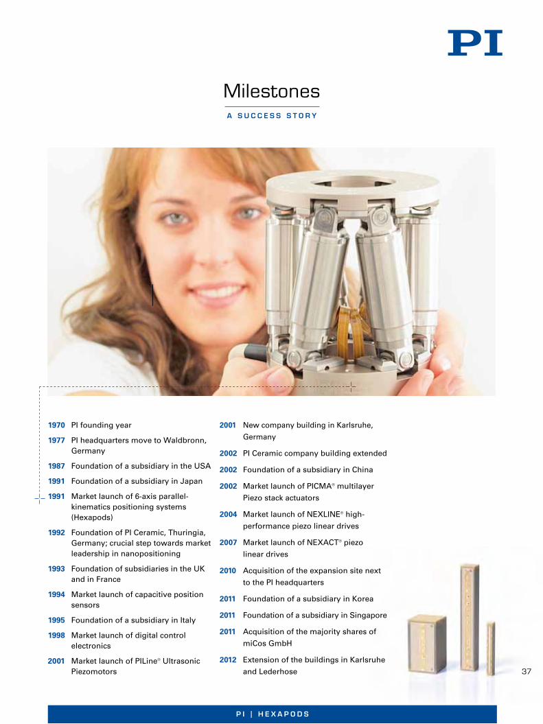
37
P I | H e x a P o d s
1970 PI founding year
1977 PI headquarters move to Waldbronn, Germany
1987 Foundation of a subsidiary in the USA
1991 Foundation of a subsidiary in Japan
1991 Market launch of 6-axis parallel- kinematics positioning systems (Hexapods)
1992 Foundation of PI Ceramic, Thuringia, Germany; crucial step towards market leadership in nanopositioning
1993 Foundation of subsidiaries in the UK and in France
1994 Market launch of capacitive position sensors
1995 Foundation of a subsidiary in Italy
1998 Market launch of digital control electronics
2001 Market launch of PILine® Ultrasonic Piezomotors
2001 New company building in Karlsruhe,
Germany
2002 PI Ceramic company building extended
2002 Foundation of a subsidiary in China
2002 Market launch of PICMA® multilayer
Piezo stack actuators
2004 Market launch of NEXLINE® high-
performance piezo linear drives
2007 Market launch of NEXACT® piezo
linear drives
2010 Acquisition of the expansion site next
to the PI headquarters
2011 Foundation of a subsidiary in Korea
2011 Foundation of a subsidiary in Singapore
2011 Acquisition of the majority shares of
miCos GmbH
2012 Extension of the buildings in Karlsruhe
and Lederhose
a s u c c e s s s t o r y
Milestones
37

38
w w w. p i . w s
1
W W W. P I . W S
P I E Z O N A N O P O S I T I O N I N GP I E Z O N A N O P O S I T I O N I N G
NANOPOS IT ION IERSYSTEME, MIKROSTELLTECHNIK & NANOMESSTECHNIK
Produktportfolio
■ Integrationsstufen vom preis-günstigen OEM-Antrieb bis zum mehrachsigen Positioniersystem
■ Beliebige, unbegrenzte Stellwege
■ Mechanisch einfach integrierbar
■ Selbsthemmend im Ruhezustand
■ Haltekraft bis 15 N
■ Geschwindigkeit bis 500 mm/s
Ultraschall-Piezomotoren können klassische Motor-Spin-del-Kombinationen oder magnetische Antriebe ersetzen und ermöglichen bei der Integration in Positioniersyste-me besonders niedrige Profilhöhen. Sie bieten auf klein-stem Bauraum dynamisches Start-/Stoppverhalten, hohe Ge schwindigkeit und Selbsthemmung. PI bietet minia-tu ri sierte Varianten, OEM-Motoren und -Antriebe sowie kom plette Positioniersysteme mit Controller an. Piezo-motoren von PI sind im Prinzip vakuumtauglich und für den Betrieb unter starken Magnet feldern geeignet.
PILine® Ultraschall-PiezomotorenKlein und schnell über große Strecken
NanopositionierungAuflösung bis in den Picometer-Bereich
■ Von linearen Achsen bis hin zu 6 Freiheitsgraden der Bewegung
■ Parallelkinematisches Prinzip für mehrachsige Systeme
■ Versionen mit direkter Positions-messung
– kapazitive Sensoren: Sub-Nanometer-Auflösung
– Inkrementelle Sensoren: Nano-meter-Auflösung, große Mess-bereiche
■ Variabel in Bauform, Stellweg undPräzisionsklasse
Nanopositioniersysteme bieten Bewegungsauflösung und Positioniergenauigkeit im Bereich von Nanometern und darunter. Die Zielposition wird innerhalb weniger Millisekunden erreicht und stabil gehalten. Als Antrieb werden Piezoaktoren oder Piezoschreitantriebe einge-setzt. Eine Optimierung der Systemperformance wird durch digitale Motion Controller erzielt. Benötigt werden diese Systeme beispielsweise in der optischen Mess-technik, Mikroskopie oder Chipherstellung. Um die erfor-derliche Positionsauflösung und Stabilität zu erzielen, entwickelt und fertigt PI die Sensorik selbst und bietet diese als eigenständige Produktlinie an.
■ Zwei Prinzipien:
– NEXLINE®: bis zu 600 N Stellkraft
– NEXACT®: schnelle Bewegung und bis zu 10 N Stellkraft
■ Integrationsstufen vom preis-günstigen OEM-Antrieb bis zum mehrachsigen Positioniersystem
■ Kompakte Bauform, variabler Stell-weg durch variable Läuferlänge
■ Nanometer-Auflösung
■ Vakuumkompatibel und nichtmagnetisch
Piezoschreitantriebe übertragen die Vorteile von Piezo-aktoren auf Anwendungen mit größeren Stellwegen. Das Zusammenspiel der Bewegung einzelner Aktoren bewirkt eine Schreitbewegung mit hoher Auflösung und Dynamik innerhalb eines Schritts und ermöglicht dabei prinzipiell unbegrenzte Stellwege. Die Aktoren sind gegen den bewegten Läufer vorgespannt. Der Antrieb ist somit im ausgeschalteten Zustand selbsthemmend ohne Halteströme oder zusätzliche mechanische Kom-ponenten. Dadurch treten keine Erwärmung oder Regel-zittern auf, der Antrieb steht stabil.
PiezoWalk® SchreitantriebeÜber Millimeter präzise positionieren
pi_120226_portfolio_musterseite.indd 1 26.03.12 13:47
nanopos it ion ing systems, micropos it ion ing tecHnology & nanometrology
Product Portfolio
Nanopositioning
Resolution Down to Picometers
Nanopositioning systems achieve motion resolutions and positioning accuracy in the nanometer range and below. The target position is achieved within a few milliseconds and stably maintained. Piezo actuators or piezo stepping drives are used as drives. Digital motion controllers optimize the performance of the system. These systems are required in optical me-trology, microscopy, or in microchip production. To achieve the necessary position resolution and stabili-ty, PI manufactures and develops the sensor systems and offers these as an independent product line.
From linear axes to motion in 6 degrees of freedom
Parallel-kinematic principle for multi-axis systems
Versions with direct position mea-surement
– capacitive sensors: Subnanometer resolution
– Incremental sensors: Nanometer resolution, wide measurement ranges
Available in a variety of designs, travel ranges, and precision classes
PiezoWalk® Stepping Drives
Precise Positioning over Several Millimeters
Piezo stepping drives transfer the advantages of con-ventional piezo actuators to applications with larger travel ranges. The interplay of the motion of indivi-dual actuators brings about a walk motion with high resolution and dynamics within a single step and thus, in principle, allows unlimited travel ranges. The actuators are prestressed against the moving slider. The drive is therefore self-locking when switched off without holding currents or additional mechanical components. There is therefore no heat dissipation or control dither, the position is maintained with a high degree of stability.
Two principles:
– NEXLINE®: Generated force up to 600 N
– NEXACT®: Fast motion and gen-erated force up to 10 N
Integration levels from an econo-mical OEM drive to a multi-axis posi-tioning system
Compact design, variable travel due to variable rod length
Nanometer resolution
Vacuum compatible and non-magnetic
PILine® Ultrasonic Piezomotors Small and Fast over Long Distances
Ultrasonic piezomotors are an alternative to the con-ventional motor spindle combinations or to mag-netic drives and allow outstandingly flat positioning systems. They offer excellent start/stop dynamics, high velocity and self-locking in a small package. PI supplies miniaturized versions, OEM motors and drives, and also complete positioning systems with controller. Piezomotors from PI are vacuum-compa-tible in principle and suitable for operation under strong magnetic fields.
Integration levels from an econo-mical OEM drive to a multi-axis posi-tioning system
Flexible travel ranges
Easy mechanical integration
Self-locking at rest
Holding force to 15 N
Velocity to 500 mm/s

39
P I | H e x a P o d s
2
■ Linearpositionierer
– Stellwege von 5 bis 1000 mm
– Geschwindigkeit bis zu 150 mm/s
– Preisgünstige Designs, Varianten als Baukastensystem
■ DC- und Stepper-Mikrometerantriebe
– Stellwege bis 50 mm und Geschwindigkeit bis zu 30 mm/s
– Auflösung bis <100 nm
■ Rotationsversteller mit unein-geschränktem Drehbereich
– bis 720 °/s
– Auflösung bis 1 μrad
– Optionale Encoder für die direktePositionsmessung
Mikropositioniersysteme bieten Bewegungsauflösungen und Positioniergenauigkeiten im Bereich zwischen eini-gen 10 μm bis zu 0,1 μm. Als Antrieb stehen bürstenlose DC- oder Schrittmotoren zur Verfügung wie auch Linear-antriebe wie PILine® Ultraschall-Piezomotoren oder NEXACT® Piezo schreitantriebe. Die Präzision des Sys-tems hängt ab von den verwendeten Komponenten für Antrieb, Positionssensor und Führung. Bei klassischen Motoren spielt außerdem die Qualität des Getriebes, der Spindel bzw. des Schneckentriebs eine wesentliche Rolle. Digitale Steuerungen ermöglichen durch geeignete Regelungs- und Linearisierungsverfahren eine Verbes-serung der Systemeigenschaften.
MikropositionierungPräzisionspositionierung auf langen Wegen
■ Für alle Antriebssysteme
■ Hochauflösende D/A- und A/D-Wandler neueste Prozessoren
■ Digitale Echtzeit-Schnittstellen
■ Umfangreiche Software und Treiber
■ Koordinateninformation für parallele Kinematiken/Hexapoden
Die Leistungsmerkmale eines Präzisions-Positioniersys-tems hängt in gleichen Maßen von der Verstellmechanik wie von der Ansteuerung ab. Digitalcontroller verarbeiten Prozesswerte wie Sensorsignal oder Positionswertvor-gabe mit speziell abgestimmten Algorithmen. So können Bewegungen auf Bahnkurven, Einschwingzeiten oder Bahnabweichungen während schneller Scanvorgänge optimiert werden.
Digitale Steuer- und RegeltechnikDas Optimum an Performance erreichen
■ Geringe bewegte Masse, geringe Trägheit
■ Gutes dynamisches Verhalten, schnelles Einschwingen
■ Geringer Bauraum
■ Hohe Steifigkeit
■ Frei definierbarer Drehpunkt
■ Minimiertes Achsübersprechen
■ Sehr gute Wiederholbarkeit
Überall dort, wo eine mehrachsige und hochpräzise Be -wegung erforderlich ist, setzt PI auf parallelkinematische Designs. Alle Antriebe wirken unmittelbar auf dieselbe bewegte Plattform. Dadurch ergeben sich Vorteile in der Präzision und Dynamik im Vergleich zu seriell gestapel-ten Achsen, bei denen sich die Fehler der Einzelachsen aufsummieren und dynamische Einbußen durch das Mitführen der oberen Achsen entstehen. Das parallel-kinematische Prinzip ist dabei unabhängig vom verwen-deten Antrieb. So können Mikro- und Nanostelltechnik-systeme mit bis zu sechs Freiheitsgraden der Bewegung umgesetzt werden.
Hexapoden — Parallelkinematische PositioniersystemeHochpräzise Positionierung in bis zu sechs Bewegungsachsen
pi_120226_portfolio_musterseite.indd 2 26.03.12 13:47
Micropositioning
Precision Positioning over Long Travel
Micropositioning systems provide motion resolution and positioning accuracies in the range between a few tens of micrometers and 0.1 µm. Brushless DC or stepper motors are available as drives, as well as linear drives such as PILine® ultrasonic piezomotors or NEXACT® piezo stepping drives. The precision of the system depends on the integrated drive, position sensor, and guides. In conventional motors, the quality of the gear, the spindle, or the worm drive play also an essential role. Digital controls with suitable control and linearization methods make it possible to improve the system characteristics. 2
■ Linearpositionierer
– Stellwege von 5 bis 1000 mm
– Geschwindigkeit bis zu 150 mm/s
– Preisgünstige Designs, Varianten als Baukastensystem
■ DC- und Stepper-Mikrometerantriebe
– Stellwege bis 50 mm und Geschwindigkeit bis zu 30 mm/s
– Auflösung bis <100 nm
■ Rotationsversteller mit unein-geschränktem Drehbereich
– bis 720 °/s
– Auflösung bis 1 μrad
– Optionale Encoder für die direktePositionsmessung
Mikropositioniersysteme bieten Bewegungsauflösungen und Positioniergenauigkeiten im Bereich zwischen eini-gen 10 μm bis zu 0,1 μm. Als Antrieb stehen bürstenlose DC- oder Schrittmotoren zur Verfügung wie auch Linear-antriebe wie PILine® Ultraschall-Piezomotoren oder NEXACT® Piezo schreitantriebe. Die Präzision des Sys-tems hängt ab von den verwendeten Komponenten für Antrieb, Positionssensor und Führung. Bei klassischen Motoren spielt außerdem die Qualität des Getriebes, der Spindel bzw. des Schneckentriebs eine wesentliche Rolle. Digitale Steuerungen ermöglichen durch geeignete Regelungs- und Linearisierungsverfahren eine Verbes-serung der Systemeigenschaften.
MikropositionierungPräzisionspositionierung auf langen Wegen
■ Für alle Antriebssysteme
■ Hochauflösende D/A- und A/D-Wandler neueste Prozessoren
■ Digitale Echtzeit-Schnittstellen
■ Umfangreiche Software und Treiber
■ Koordinateninformation für parallele Kinematiken/Hexapoden
Die Leistungsmerkmale eines Präzisions-Positioniersys-tems hängt in gleichen Maßen von der Verstellmechanik wie von der Ansteuerung ab. Digitalcontroller verarbeiten Prozesswerte wie Sensorsignal oder Positionswertvor-gabe mit speziell abgestimmten Algorithmen. So können Bewegungen auf Bahnkurven, Einschwingzeiten oder Bahnabweichungen während schneller Scanvorgänge optimiert werden.
Digitale Steuer- und RegeltechnikDas Optimum an Performance erreichen
■ Geringe bewegte Masse, geringe Trägheit
■ Gutes dynamisches Verhalten, schnelles Einschwingen
■ Geringer Bauraum
■ Hohe Steifigkeit
■ Frei definierbarer Drehpunkt
■ Minimiertes Achsübersprechen
■ Sehr gute Wiederholbarkeit
Überall dort, wo eine mehrachsige und hochpräzise Be -wegung erforderlich ist, setzt PI auf parallelkinematische Designs. Alle Antriebe wirken unmittelbar auf dieselbe bewegte Plattform. Dadurch ergeben sich Vorteile in der Präzision und Dynamik im Vergleich zu seriell gestapel-ten Achsen, bei denen sich die Fehler der Einzelachsen aufsummieren und dynamische Einbußen durch das Mitführen der oberen Achsen entstehen. Das parallel-kinematische Prinzip ist dabei unabhängig vom verwen-deten Antrieb. So können Mikro- und Nanostelltechnik-systeme mit bis zu sechs Freiheitsgraden der Bewegung umgesetzt werden.
Hexapoden — Parallelkinematische PositioniersystemeHochpräzise Positionierung in bis zu sechs Bewegungsachsen
pi_120226_portfolio_musterseite.indd 2 26.03.12 13:47
PICMA® Piezo Ceramic Multilayer Actuators
Higher Reliability and Performance
PI uses its own PICMA® piezo ceramic actuators in its high-precision positioning systems for nanoposi- tioning. Their all-ceramic insulation makes for high-est humidity resistance which results in superior re-liability and lifetime. With the piezo ceramics deve-lopment being part of the PI group a fast and flexible adaptation to customers‘ requirements is possible.
Long lifetime, unaffected by humidity
Flexible cross sections and displacements
Resolution to below one nanometer
Response time to below one millisecond
For all drive systems
High resolution D/A and A/D con-verters, state of the art processor technology
Digital real-time interfaces
Extensive software and drivers
Information on coordinates for parallel kinematics/Hexapods
Digital Control Technology
Achieve the Optimum in Performance
The performance characteristics of a precision po-sitioning system depend equally on the stage me- chanics and the control. Digital controllers use spe-cially adapted algorithms to process process values such as sensor signal or position target value. Mo-tions on trajectories, settling times, or trajectory de-viations can thus be optimized during fast scanning operations.
Linear positioners
– Travel ranges between 5 and 1000 mm
– Velocity to 150 mm/s
– Low-cost designs, variants as modular system
DC and stepper micrometer drives
– Travel ranges to 50 mm and veloci-ty to 30 mm/s
– Resolution to <100 nm
Rotary stage with unlimited slewing range
– to 720 °/s
– Resolution to 1 µrad
– ncremental encoders for direct po-sition measurement as an optional extra

w w w. p i . w s
W W W. P I . W S
P I E Z O N A N O P O S I T I O N I N G
JAPAN
PI Japan Co., Ltd.Tachikawa Business Center Bldg. 5F2-38-5 Akebono-choTachikawa-shi, Tokyo 190-0012Tel. +81 (42) 526 7300Fax +81 (42) 526 [email protected]
PI Japan Co., Ltd.Hanahara Daini Bldg. #7034-11-27 NishinakajimaYodogawa-ku, Osaka-shiOsaka 532-0011Tel. +81 (6) 6304 5605Fax +81 (6) 6304 [email protected]
ITALY
Physik Instrumente (PI) S. r. l.Via G. Marconi, 2820091 Bresso (MI)Tel. +39 (02) 665 011 01Fax +39 (02) 610 396 [email protected]
CHINA
Physik Instrumente (PI Shanghai) Co., Ltd.Building No. 7-106Longdong Avenue 3000201203 Shanghai, ChinaTel. +86 (21) 518 792 98Fax +86 (21) 687 900 [email protected]
UK & IRELAND
PI (Physik Instrumente) Ltd.Trent House, University Way,Cranfield Technology Park,Cranfield, Bedford MK43 0ANTel. +44 (1234) 756 360Fax +44 (1234) 756 [email protected]
FRANCE
PI France S.A.S.244 bis, avenue Marx Dormoy92120 MontrougeTel. +33 (1) 55 22 60 00Fax +33 (1) 41 48 56 [email protected]
SubsidiariesUSA (East) & CANADA USA (West) & MEXIKO
PI (Physik Instrumente) L.P.16 Albert St.Auburn, MA 01501Tel. +1 (508) 832 3456Fax +1 (508) 832 [email protected]
PI (Physik Instrumente) L.P.5420 Trabuco Rd., Suite 100Irvine, CA 92620Tel. +1 (949) 679 9191Fax +1 (949) 679 [email protected]
SOUTH EAST ASIA
PI (Physik Instrumente) Singapore LLP20 Sin Ming Lane #05-60 Midview CitySingapore 573968 Tel. +65 665 98400Fax +65 665 [email protected] ID / MY / PH / SG / TH
KOREA
PI Korea Ltd.6F Jeongu Bldg.Cheonho-Daero 1111Gangdong-gu138-814 SeoulTel. +82 2475 0060Fax +82 2475 [email protected]
HeadquartersGERMANY
Physik Instrumente (PI)GmbH & Co. KGAuf der Roemerstr. 176228 Karlsruhe/PalmbachTel. +49 (721) 4846-0Fax +49 (721) [email protected]
PI miCos GmbHEschbach [email protected]
PI Ceramic [email protected]
pi_rueckseite_e_A4.indd 1 23.01.12 11:24
W W W. P I . W S
P I E Z O N A N O P O S I T I O N I N G
JAPAN
PI Japan Co., Ltd.Tachikawa Business Center Bldg. 5F2-38-5 Akebono-choTachikawa-shi, Tokyo 190-0012Tel. +81 (42) 526 7300Fax +81 (42) 526 [email protected]
PI Japan Co., Ltd.Hanahara Daini Bldg. #7034-11-27 NishinakajimaYodogawa-ku, Osaka-shiOsaka 532-0011Tel. +81 (6) 6304 5605Fax +81 (6) 6304 [email protected]
ITALY
Physik Instrumente (PI) S. r. l.Via G. Marconi, 2820091 Bresso (MI)Tel. +39 (02) 665 011 01Fax +39 (02) 610 396 [email protected]
CHINA
Physik Instrumente (PI Shanghai) Co., Ltd.Building No. 7-106Longdong Avenue 3000201203 Shanghai, ChinaTel. +86 (21) 518 792 98Fax +86 (21) 687 900 [email protected]
UK & IRELAND
PI (Physik Instrumente) Ltd.Trent House, University Way,Cranfield Technology Park,Cranfield, Bedford MK43 0ANTel. +44 (1234) 756 360Fax +44 (1234) 756 [email protected]
FRANCE
PI France S.A.S.244 bis, avenue Marx Dormoy92120 MontrougeTel. +33 (1) 55 22 60 00Fax +33 (1) 41 48 56 [email protected]
SubsidiariesUSA (East) & CANADA USA (West) & MEXIKO
PI (Physik Instrumente) L.P.16 Albert St.Auburn, MA 01501Tel. +1 (508) 832 3456Fax +1 (508) 832 [email protected]
PI (Physik Instrumente) L.P.5420 Trabuco Rd., Suite 100Irvine, CA 92620Tel. +1 (949) 679 9191Fax +1 (949) 679 [email protected]
SOUTH EAST ASIA
PI (Physik Instrumente) Singapore LLP20 Sin Ming Lane #05-60 Midview CitySingapore 573968 Tel. +65 665 98400Fax +65 665 [email protected] ID / MY / PH / SG / TH
KOREA
PI Korea Ltd.6F Jeongu Bldg.Cheonho-Daero 1111Gangdong-gu138-814 SeoulTel. +82 (2) 475-0060Fax +82 (2) [email protected]
HeadquartersGERMANY
Physik Instrumente (PI)GmbH & Co. KGAuf der Roemerstr. 176228 KarlsruheTel. +49 (721) 4846-0Fax +49 (721) [email protected]
PI miCos GmbHEschbach [email protected]
PI Ceramic [email protected]
pi_rueckseite_e_A4.indd 1 25.06.12 13:56
P I E Z O T E C H N O L O G Y
PiezoelectricCeramic Products
FUNDAMENTALS, CHARACTERISTICS AND APPLICATIONS
P IEZOCERAMICMATER IALS
COMPONENTS
INTEGRAT ION
P I E Z O N A N O P O S I T I O N I N G
Headquarters
GERMANY
Physik Instrumente (PI)GmbH & Co. KGAuf der Roemerstraße 176228 Karlsruhe/PalmbachTel: +49 (721) 4846-0Fax: +49 (721) 4846-1019Email: [email protected]
SubsidiariesUSA & CANADA (East)
PI (Physik Instrumente) L.P.16 Albert St.Auburn, MA 01501Tel: +1 (508) 832 3456Fax: +1 (508) 832 0506Email: [email protected]
JAPAN
PI Japan Co., Ltd.Akebono-cho 2-38-5Tachikawa-shiTokyo 190-0012Tel: +81 (42) 526 7300Fax: +81 (42) 526 7301Email: [email protected]
PI Japan Co., Ltd.Hanahara Dai-Ni-Building #7034-11-27 Nishinakajima,Yodogawa-ku, Osaka-shi,Osaka 532-0011Tel: +81 (6) 6304 5605Fax: +81 (6) 6304 5606Email: [email protected]
UK & IRELAND
PI (Physik Instrumente) Ltd.Trent House, University Way,Cranfield Technology Park,Cranfield, Bedford MK43 0ANTel: +44 (1234) 756 360Fax: +44 (1234) 756 369Email: [email protected]
FRANCE
PI France S.A.S.244 bis, avenue Marx Dormoy92120 MontrougeTel: +33 (1) 55 22 60 00Fax: +33 (1) 41 48 56 62Email: [email protected]
ITALY
Physik Instrumente (PI) S. r. l.Via G. Marconi, 2820091 Bresso (MI)Tel: +39 (02) 665 011 01Fax: +39 (02) 610 396 56Email: [email protected]
CHINA
Physik Instrumente(PI Shanghai) Co., Ltd.Building No. 7-106Longdong Avenue 3000201203 ShanghaiTel: +86 (21) 518 792 98Fax: +86 (21) 687 900 98Email: [email protected]
PI Ceramic GmbHLindenstraße07589 LederhoseTel: +49 (36604) 882-0Fax: +49 (36604) 882-4109Email: [email protected]
USA & CANADA (West)& MEXIKO
CA
T12
5EP
iezo
elec
tric
Cer
amic
Pro
du
cts
11/0
5/09
.2,7
;Su
bje
ctto
chan
ge
wit
ho
ut
no
tice
.©P
hys
ikIn
stru
men
te(P
I)G
mb
H&
Co
.KG
2011PI (Physik Instrumente) L.P.
5420 Trabuco Rd., Suite 100Irvine, CA 92620Tel: +1 (949) 679 9191Fax: +1 (949) 679 9292Email: [email protected]
W W W . P I C E R A M I C . C O M
PI General Catalog
Request it now!The 530 page hardbound catalogue fromPI is the most comprehensive referencebook on the fundamentals of nanoposi-tioning, piezo systems and micro-positioning technology yet. The catalogcontains 200 product families, with morethan 1000 drawings, graphs, images andtechnical diagrams.
11_0410_PIC_Kat_E_Umschlag.qxd:Layout 3 12.05.2011 10:27 Uhr Seite 1
P I E Z O T E C H N O L O G Y
Piezokeramische Materialienund Bauelemente
GRUNDLAGEN, EIGENSCHAFTEN UND ANWENDUNGEN
WERKSTOFFE
KOMPONENTEN
INTEGRAT ION
P I E Z O N A N O P O S I T I O N I N G
Hauptsitze
DEUTSCHLAND
Physik Instrumente (PI)GmbH & Co. KGAuf der Römerstraße 176228 Karlsruhe/PalmbachTel: +49 (721) 4846-0Fax: +49 (721) 4846-1019Email: [email protected]
NiederlassungenUSA (OST) & KANADA
PI (Physik Instrumente) L.P.16 Albert St.Auburn, MA 01501Tel: +1 (508) 832 3456Fax: +1 (508) 832 0506Email: [email protected]
JAPAN
PI Japan Co., Ltd.Akebono-cho 2-38-5Tachikawa-shiTokyo 190-0012Tel: +81 (42) 526 7300Fax: +81 (42) 526 7301Email: [email protected]
PI Japan Co., Ltd.Hanahara Dai-Ni Building #7034-11-27 Nishinakajima,Yodogawa-ku, Osaka-shi,Osaka 532-0011Tel: +81 (6) 6304 5605Fax: +81 (6) 6304 5606Email: [email protected]
ENGLAND & IRLAND
PI (Physik Instrumente) Ltd.Trent House, University Way,Cranfield Technology Park,Cranfield, Bedford MK43 0ANTel: +44 (1234) 756 360Fax: +44 (1234) 756 369Email: [email protected]
FRANKREICH
PI France S.A.S.244 bis, avenue Marx Dormoy92120 MontrougeTel: +33 (1) 55 22 60 00Fax: +33 (1) 41 48 56 62Email: [email protected]
ITALIEN
Physik Instrumente (PI) S. r. l.Via G. Marconi, 2820091 Bresso (MI)Tel: +39 (02) 665 011 01Fax: +39 (02) 610 396 56Email: [email protected]
CHINA
Physik Instrumente(PI Shanghai) Co., Ltd.Building No. 7-106Longdong Avenue 3000201203 ShanghaiTel: +86 (21) 518 792 98Fax: +86 (21) 687 900 98Email: [email protected]
PI Ceramic GmbHLindenstraße07589 LederhoseTel: +49 (36604) 882-0Fax: +49 (36604) 882-4109Email: [email protected]
USA (WEST) & MEXIKO
CA
T12
5DP
iezo
kera
mis
che
Wer
ksto
ffe
11/0
3/14
.3,0
;Än
der
un
gen
vorb
ehal
ten
.©
Ph
ysik
Inst
rum
ente
(PI)
Gm
bH
&C
o.K
G20
11
PI (Physik Instrumente) L.P.5420 Trabuco Rd., Suite 100Irvine, CA 92620Tel: +1 (949) 679 9191Fax: +1 (949) 679 9292Email: [email protected]
W W W . P I C E R A M I C . D E
Der PI Gesamtkatalog
Jetzt anfordern!Auf über 500 Seiten präsentiert der PIGesamtkatalog Grundlagen und Techno-logie von Nanopositionierung, Piezo-systemen und Mikropositionierung.Mehr als 200 Produktfamilien werdenvorgestellt und mit über 1000 Abbildun-gen, Messkurven und Prinzipskizzenillustriert.
11_0409_PIC_Kat_Umschlag.qxd:Layout 3 15.03.2011 12:56 Uhr Seite 1
BR
O14
E P
aral
lel K
inem
atic
s 12
/08/
15.1
; Su
bje
ct t
o c
han
ge
wit
ho
ut
no
tice
. © P
hys
ik In
stru
men
te (
PI)
Gm
bH
& C
o. K
G 2
012
© Physik Instrumente (PI) GmbH & Co. KGAll contents, including texts, graphics, data etc., as well as their layout, are subject to copyright and other protective laws. Any copying, modi-fication or redistribution in whole or in parts is subject to a written permission of PI.
NoteAlthough the information in this document has been compiled with the greatest care, errors cannot be ruled out completely. Therefore, we cannot guarantee for the information being complete, correct and up to date. PI reserves the right to supplement or change the information provided without prior notice.