fdot automated quantities (part 2) -...
TRANSCRIPT

Production Support Office | CADD
FDOT Automated Quantities(Part 2)
Kandi Daffin
CADD Support Specialist

Objectives
Explore and learn how to use the tools in the Quantity Workflow to develop Plan Summary Boxes and Summary of Quantity Sheets, export the data to Designer Interface, and create the Summary of Pay Items Sheet.
• Review Plan Summary Box Requirements
• Create Summary Boxes through Linked Data Manager
• Automated
• Non-Automated
• Generate Reports in Quantity Manager to use to fill in Summary Box information
• Get quantity information to Designer Interface
• Access AASHTOWare Project Reporting to get Project Summary Reports for the Summary of Pay Items
• Create Summary of Pay Items Sheet

FDOT Standards
• ALL quantities are to be documented by location on Plan Summary Boxes for Roadway & Structures components.
• Plan Summary Boxes are to be located on the Summary of Quantities sheets.• Plan Set Location
• Roadway – keep in same order sequence behind the Typical Section sheets
• Structures – Directly behind the Summary of Pay Items in the General Bridge section(or behind the Key Sheet if no Summary of Pay Items sheet)
• File Name• Roadway – SUMQRD**
• Structures – B#SumofQuantities*
• Sheet Prefix• Roadway – SQ-
• Structures – BQ#-
FDOT Standards
• All other components (i.e. Signing & Pavement Markings, Signalization, Lighting, etc.) are to use Tabulation of Quantities sheets.
• Drainage systems are to be documented on the Summary of Drainage Structures sheets same as they have always been handled.
• Do NOT add pay item numbers.
• Incidental drainage items to a project can be documented on the Summary of Miscellaneous Drainage Items. Linear and Each items
• Intended for projects with Miscellaneous Drainage Items or on projects with minimal drainage work, i.e. replacing broken inlet tops or moving structures to accommodate added turn lanes, etc.
• Do NOT include items in this box that are included on the Summary of Drainage Structures sheets.

FDOT Standards
• A listing of standard summary boxes is located in Chapter 8 of the BOE.
http://www.fdot.gov/programmanagement/Estimates/BasisofEstimates/BOEManual/Files/Chapter08SummaryBoxes.pdf
• Do NOT create non-standard boxes or modify current summary boxes with Non-Standard columns or rows.
• Formatting in MicroStation is controlled through Excel files.
• FDOT templates have already been formatted for use.
• Columns and rows may be adjusted or hidden in Excel and change is reflected in MicroStation when link is updated.
• Columns may be deleted when not used. However do NOT delete the Construction Remarks or “F” columns.
• When copying data into the template files, make sure to use the“Values Only” option to paste.

Linked Data Manager (LDM)
• FDOT tool that uses Excel templates to generate Plan Summary Boxes.
• Creates a link between the Excel file and the MicroStation dgn file for easy updates.
• Always make changes to spreadsheet, save and then right click on the linkin the list and choose Update Now.
Note: this is a ONE WAY process. Changes made in MicroStation cannot be updated to Excel.

Linked Data Manager (LDM)
Automating Plan Summary Boxes
• When creating a link use the Create New from Quantities option.
• Select the QM database (*.mdb)
• Select the Summary to be created
• Save the file to the Calculations directory of the project

Linked Data Manager (LDM)
Automating Plan Summary Boxes• Adjust the link settings and select OK to
place the links and sheet borders

Linked Data Manager (LDM)
Automating Plan Summary Boxes
• Once placed, the plan sheet borders are not linked and can be moved or deleted as needed. Summary boxes can also be moved. There will be a separate link for each summary box placed.
• If a quantity changes and the boxes need to be updated, the same process can be used. Use LDM’s Create New from Quantities and overwrite the existing Excel file in the Calculations folder, then cancel instead of placing new summary boxes. Update the existing links through LDM.
Note: If there are any customizations in the Excel file (i.e. columns hidden or widened) they will need to be reformatted in the newly created Excel file.

Linked Data Manager (LDM)
Creating Plan Summary Boxes from Templates
• When creating a link, select Create New From Template for summary boxes that are not included in the automated list.
Note: The templates are available for ALL summary boxes in the drop down for designers who do not use D&C Manager or Quantity Manager.

Linked Data Manager (LDM)
Creating Plan Summary Boxes from Templates• Save the Excel file to the Calculations
folder in the project directory.
• Once saved, the Link Information dialog will come back up, select the Box1 worksheet from the dropdown.
• Select the Graphic Settings.
• Select desired link settings.
• Click OK and click in the MicroStation file to place the link and graphics.

Linked Data Manager (LDM)
Creating Plan Summary Boxes from Templates• Right click on the link in the LDM tool
box and select Open Source.
• Once open, add and modify data as necessary in the Excel file and save.
• In MicroStation, right click on the link in LDM again and select Update Now.
Note: Quantity Manager will generate reports which can speed up this process.

Linked Data Manager (LDM)
Creating Plan Summary Boxes from Templates
• Summary of Structures Quantities
• Place the Plan Sheet at a scale of 12
• Do not turn on the option to use the Drawing Scale

Quantity Manager (QM)
Generating Reports
• In QM, set the Trns*port Grouping setting to the appropriate category (Roadway = 0200)
• Select the desired Pay Item in the Pay Item Pane.
• Select Tools > Reports > Create from the QM menu.
Quantity Manager (QM)
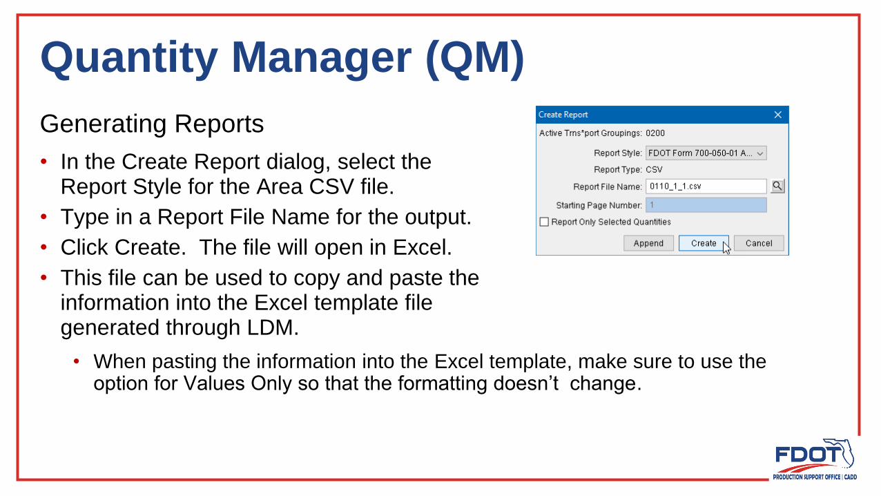
Generating Reports
• In the Create Report dialog, select theReport Style for the Area CSV file.
• Type in a Report File Name for the output.
• Click Create. The file will open in Excel.
• This file can be used to copy and paste theinformation into the Excel template filegenerated through LDM.
• When pasting the information into the Excel template, make sure to use the option for Values Only so that the formatting doesn’t change.

Quantity Manager to Designer Interface
Quantities Workflow
1. Export the Project Header information (xml file) from Designer Interface.
2. Import the project header info into Quantity Manager Project Preferences.
3. Export the quantities report from Quantity Manager (xml file).
4. Import the quantities to the project in Designer Interface.

Quantity Manager to Designer Interface
Quantities Workflow
1. Export the Project Header information (xml file) from Designer Interface.
• This can be done in 2 locations…
• Project List
• Project Details (Click Update in the
Project column to display Project
Details)
• On either screen, select Export Header.

Quantity Manager to Designer Interface
Quantities Workflow
1. Export the Project Header information (xml file) from Designer Interface.
• Select the drop down option beside the Save option and choose Save As.
• Save the xml to the project discipline directory (i.e. Roadway).

Quantity Manager to Designer Interface
Quantities Workflow
2. Import the project header info intoQuantity Manager Project Properties.
• In QM, select Project > Properties.
• In the Project Properties dialog, selectProject > Import aecXML Infrastructure v33 Project
• Select the downloaded file, then select Open.

Quantity Manager to Designer Interface
Quantities Workflow
2. Import the project header info into Quantity Manager Project Properties.
• The Project Properties dialog opens with a new tab for the Trns*port Groupings.
• Select the desired options and then click Import.

Quantity Manager to Designer Interface
Quantities Workflow
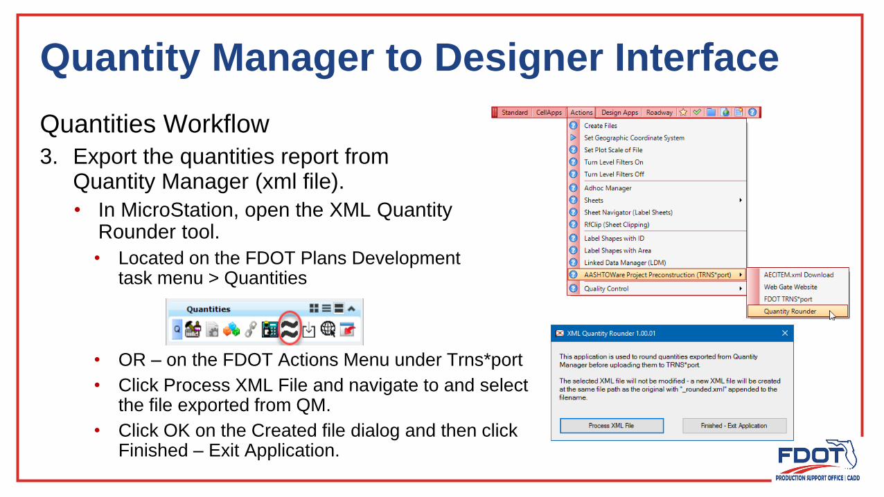
3. Export the quantities report from Quantity Manager (xml file).
• Make sure the Trns*port Grouping is set correctly.
• In the Payitem Table view of the Pay Item Pane, select all of the pay items desired to be exported.

Quantity Manager to Designer Interface
Quantities Workflow
3. Export the quantities report from Quantity Manager (xml file).
• On the Export dialog, select the ExportStyle, aecXML + Funding
• Toggle ON the Rename option and leaveas the default “DesignEstimate”.
• Type in a name for the xml file generated.
• Click Export.
• Click OK on the information dialog about Properties missing. This is normal.The file generated will have all the necessary information.
• Click OK on the Export Complete information dialog.
Quantity Manager to Designer Interface
Quantities Workflow
3. Export the quantities report fromQuantity Manager (xml file).
• In MicroStation, open the XML QuantityRounder tool.
• Located on the FDOT Plans Developmenttask menu > Quantities
• OR – on the FDOT Actions Menu under Trns*port
• Click Process XML File and navigate to and selectthe file exported from QM.
• Click OK on the Created file dialog and then clickFinished – Exit Application.

Quantity Manager to Designer Interface
Quantities Workflow
4. Import the quantities to the project in Designer Interface.
• On either the Project List or Project Details view, click on Import.
• Click on Select Files… and then navigate to the file exported and then rounded from the project directory. (It will have _Rounded appended to the file name.)
• Once selected click on Upload file.

Quantity Manager to Designer Interface
Quantities Workflow
4. Import the quantities to the project in Designer Interface.
• The results will show up on the screen. This is ALL or nothing.
• Green – LoadSuccessful
• Red – Errors(nothing loaded)

Summary of Pay Items
• Access Webgate Reporting
• From Designer Interface
• From Webgate site
• Select Designers, Estimators, and Reviewers > Project Edit Report
• This report should be run firstto identify any errors with thepay items loaded on the project.

Summary of Pay Items
• Access Webgate Reporting
• From Designer Interface
• From Webgate site
• Select General Reports > Summary of Pay Items Report

Summary of Pay Items
• Select the Project
• Select Report Type: CADD File
• Click Submit
• Select the Save As option
• Rename the file if the Project Header file is named the same as the default.
Note: The Auto-Generate Proposal Sections is now available for Designers to run.
• If a proposal has been generated for a project, run this report before creating the Summary of Pay Items if pay items have been added or modified.

Summary of Pay Items
• In MicroStation, select the FDOT TRNS*port tool
OR

Summary of Pay Items
• Select the Browse button and navigate to the saved Summary of Pay Items report xml file.
• County and Financial Number are pulled in from the XML file.
• Label Sheet is toggled on by default.
• Optional
• Click Load Summary of Pay Items

Questions?
Thank you for joining today’s session!
Need HELP? Contact me…
(850) 414-4289
E-mail: [email protected]
http://www.fdot.gov/cadd/
FDOT CADD Support Forum On-line
https://communities.bentley.com/communities/user_communities/fdot_cadd_support/