fdot district iv its disaster recovery plan - smart … recovery plan 06_feb_02 fina… · fdot...
TRANSCRIPT
FDOT District IV ITS Disaster Recovery Plan
Revision: 8.0 02/02/06
ii
Table of Contents Section 1.0: Introduction .......................................................................................... 1
1.1 Document Objectives..................................................................................................1 1.2 Overview of Broward ITS Infrastructure ...................................................................2
1.2.1 FDOT Broward TMC Networks.............................................................................................. 2 1.2.2 Data/Application Server Backup Procedures...................................................................... 2 1.2.3 Broward TMC Computer Procedures................................................................................... 2 1.2.4 Server Backup Storage Location.......................................................................................... 3
1.3 Broward TMC Computer Network Maintenance .......................................................3 1.3.1 Servers .................................................................................................................................... 3 1.3.2 Cisco PBX Telephone System .............................................................................................. 4
1.4 ITS Field Devices.........................................................................................................4 1.4.1 Fiber Optic–Based Communication System ....................................................................... 4 1.4.2 DMS Signs............................................................................................................................... 4 1.4.3 CCTV Cameras ....................................................................................................................... 5 1.4.4 Communications with Road Rangers .................................................................................. 5 1.4.5 Center-to-Center Communications ...................................................................................... 5
Section 2.0: Broward Implementation Plan............................................................. 6 2.1 Key Assumptions........................................................................................................6 2.2 Initial Failure ................................................................................................................7 2.3 Crisis Designations.....................................................................................................7
2.3.1 Assessing the Magnitude of a Crisis ................................................................................... 8 2.3.2 Chain of Command/Decision Making................................................................................... 8 2.3.3 Coordinating with Other Agencies or Districts................................................................... 8 2.3.4 Procedures for Communicating with the News Media ....................................................... 9
2.4 Staff Roles and Responsibilities................................................................................9 2.5 Disaster Recovery Plan Flowchart ..........................................................................10
2.5.1 Description of Figure 1 ........................................................................................................ 10 2.5.2 Description of Figure 2 ........................................................................................................ 11 2.5.3 Description of Figure 3 ........................................................................................................ 12 2.5.4 Description of Figure 4 ........................................................................................................ 14
Section 3.0: Palm Beach ITMS Plan....................................................................... 20 3.1 Overview of ITMS Infrastructure ..............................................................................20
3.1.1 TMC Facility .......................................................................................................................... 20 3.1.2 Power System....................................................................................................................... 20 3.1.3 Computer Servers ................................................................................................................ 20 3.1.4 Workstations......................................................................................................................... 21 3.1.5 Network Equipment.............................................................................................................. 21 3.1.6 Telephones ........................................................................................................................... 21 3.1.7 Radios ................................................................................................................................... 21 3.1.8 ADT Security System........................................................................................................... 21 3.1.9 Field Equipment ................................................................................................................... 22 3.1.10 Communication with Road Rangers .................................................................................. 22 3.1.11 Center-to-Center Communications .................................................................................... 22
3.2 ITMS Plan Implementation........................................................................................23 3.2.1 Overview ............................................................................................................................... 23 3.2.2 Key Assumptions................................................................................................................. 23
3.3 Initial Failure ..............................................................................................................23 3.4 Assessing the Magnitude of a Crisis.......................................................................24
3.4.1 Crisis Designations.............................................................................................................. 24 3.4.2 Chain of Command/Decision Making................................................................................. 25 3.4.3 Coordinating with Other Agencies or Districts................................................................. 25
FDOT District IV ITS Disaster Recovery Plan
Revision: 8.0 02/02/06
iii
3.4.4 Procedures for Communicating with the News Media ..................................................... 26 3.5 Staff Roles and Responsibilities..............................................................................26 3.6 Employee Vacation Status .......................................................................................27 3.7 Disaster Recovery Plan Flowchart ..........................................................................27
3.7.1 Figure 5 – Initial Disaster Recovery Flowchart ................................................................. 28 3.7.2 Figure 6 – Category 2 Disaster Recovery Flowchart ........................................................ 28 3.7.3 Figure 7 – Category 3 Disaster Recovery Flowchart ........................................................ 29 3.7.4 Figure 8 – Category 4 Disaster Recovery Flowchart ........................................................ 30
Section 4.0: Plan Administration ........................................................................... 35 4.1 Distribution ................................................................................................................35 4.2 Plan Off-Site Location...............................................................................................35 4.3 Identification of the Person in Charge of the Plan .................................................35 4.4 Training ......................................................................................................................35
4.4.1 Initial Operator Training ...................................................................................................... 36 4.4.2 Quarterly Plan Review with Senior Management.............................................................. 36
Section 5.0: Plan Performance Metrics ................................................................. 37 5.1 After-Action Report ...................................................................................................37 5.2 Initial Plan Validation ................................................................................................37 5.3 Plan Implementation Drills .......................................................................................37
5.3.1 Semiannual Implementation Drills ..................................................................................... 38 5.3.2 Annual Implementation Drills ............................................................................................. 38
Section 6.0: Broward TMC Hurricane Plan............................................................ 39 6.1 Scope of the Broward TMC Hurricane Plan ............................................................39 6.2 Hurricane Categories ................................................................................................40 6.3 Compliance................................................................................................................41
6.3.1 Develop Hurricane Preparedness Plan.............................................................................. 41 6.3.2 Establish Redundant Communications for Road Rangers, SIRV, and TMC.................. 41 6.3.3 Place TMC Staff at County EOC.......................................................................................... 42 6.3.4 Develop Emergency Contracts ........................................................................................... 42 6.3.5 Train In-house Staff to Repair ITS Field Devices .............................................................. 42 6.3.6 Monitor Volumes and Speed Data on the State Highway System .................................. 43 6.3.7 Develop and Maintain a Spare Parts Inventory................................................................. 43 6.3.8 Establish Inventory of Portable Traffic Control Devices.................................................. 43 6.3.9 Maintain Generators to Power Critical ITS Field Devices ................................................ 43
6.4 Broward TMC Facility Procedures...........................................................................47 6.4.1 Broward TMC Facility Preparation ..................................................................................... 47 6.4.2 Coordination with Regional TMC........................................................................................ 47 6.4.3 TMC Severe-Weather Supplies ........................................................................................... 48 6.4.4 Severe-Weather Radio ......................................................................................................... 48 6.4.5 TMC Facility Generator........................................................................................................ 48 6.4.6 ITS Field Device Preparation............................................................................................... 49
6.5 FDOT Broward TMC Facility Recovery....................................................................49 6.5.1 Emergency Communication Teams ................................................................................... 50 6.5.2 Damage Assessment Teams............................................................................................... 50
6.6 Broward TMC HURRICANE PLAN Flowchart..........................................................50 6.6.1 Description of Figure 11 ...................................................................................................... 50 6.6.2 Description of Figure 12 ...................................................................................................... 51
Section 7.0: Palm Beach ITMS Hurricane Preparedness Plan............................ 56 7.1 Introduction ...............................................................................................................56 7.2 Hurricane Categories ................................................................................................57 7.3 Palm Beach ITMS Facility .........................................................................................58
7.3.1 Road Ranger Redundant Communication Means ............................................................ 58 7.3.2 Develop Emergency Contracts ........................................................................................... 58 7.3.3 Backup Communication Means for External TMC Use .................................................... 58 7.3.4 Place TMC Staff at County Emergency Operations Centers ........................................... 58
FDOT District IV ITS Disaster Recovery Plan
Revision: 8.0 02/02/06
iv
7.3.5 Develop and Maintain a Spare Parts Inventory................................................................. 58 7.3.6 Generator Power for Critical ITS Field Devices ................................................................ 59 7.3.7 Portable Traffic Control Devices - DMS ............................................................................. 59 7.3.8 Monitor Volumes and Speed Data on the State Highway System .................................. 59
7.4 FDOT PB ITMS Facility Preparation.........................................................................59 7.4.1 Palm Beach ITMS Facility and ITS Field Device Preparation .......................................... 59 7.4.2 TMC Severe-Weather Supplies ........................................................................................... 59 7.4.3 Severe-Weather Radio ......................................................................................................... 59 7.4.4 TMC Facility Generator........................................................................................................ 60 7.4.5 ITS Field Device Preparation............................................................................................... 60
7.5 ITMS Facility Operational Status during Storm Event ...........................................60 7.5.1 ITS Field Device and Infrastructure during Storm Event ................................................. 60 7.5.2 ITMS Facility Recovery ........................................................................................................ 60 7.5.3 Emergency Communication Teams ................................................................................... 61 7.5.4 Damage Assessment Teams............................................................................................... 61 7.5.5 ITS Field Device and Infrastructure Recovery .................................................................. 61
Appendix A: Broward TMC Contact List ................................................................... 62 Appendix B: FDOT District IV Emergency Plans..................................................... 63 Appendix C: FDOT Broward TMC Severe-Weather Supplies .................................. 64 Appendix D: Palm Beach ITMS Contact List............................................................. 65 Appendix E: ITMS Severe-Weather Supplies............................................................ 66 Appendix F: ITMS Severe-Weather Plan ................................................................... 67 Section 1.0: Participant Roles................................................................................ 68
1.1 Safeguarding Lives and Property ............................................................................68 1.2 System Operation......................................................................................................68 1.3 Agency Coordination................................................................................................69
1.3.1 General .................................................................................................................................. 69 1.3.2 Road Ranger Service Patrol................................................................................................ 69 1.3.3 Palm Beach County Emergency Operations Center (EOC) ............................................. 69 1.3.4 FDOT West Palm Beach Maintenance................................................................................ 70 1.3.5 SunGuide 511 Traveler Information ................................................................................... 70
Schedule ...................................................................................................................... 70 1.4 Phase A - Before Hurricane......................................................................................71
1.4.1 ITMS....................................................................................................................................... 71 1.4.2 Field Device Maintenance Contractor ................................................................................ 71
1.5 Phase B - Hurricane Alert .........................................................................................71 1.5.1 ITMS....................................................................................................................................... 71 1.5.2 Field Device Maintenance Contractor ................................................................................ 72
1.6 Phase C - Hurricane Watch ......................................................................................72 1.6.1 ITMS....................................................................................................................................... 72 1.6.2 Field Device Maintenance Contractor ................................................................................ 72
1.7 Phase D - Hurricane Warning...................................................................................72 1.7.1 ITMS....................................................................................................................................... 72 Field Device Maintenance Contractor............................................................................................. 73
1.8 Phase E - After Hurricane.........................................................................................73 1.8.1 ITMS....................................................................................................................................... 73 1.8.2 Field Device Maintenance Contractor ................................................................................ 74
FDOT District IV ITS Disaster Recovery Plan
Revision: 8.0 02/02/06
v
List of Figures Figure 1: Initial Disaster Recovery Flowchart for Broward TMC.......................... 16 Figure 2: Category 2 Disaster Recovery Flowchart for Broward TMC................. 17 Figure 3: Category 3 Disaster Recovery Flowchart for Broward TMC................. 18 Figure 4: Category 4 Disaster Recovery Flowchart for Broward TMC................. 19 Figure 5: Initial Disaster Recovery Flowchart for Palm Beach ITMS ................... 31 Figure 6: Category 2 Disaster Recovery Flowchart for Palm Beach ITMS .......... 32 Figure 7: Category 3 Disaster Recovery Flowchart for Palm Beach ITMS .......... 33 Figure 8: Category 4 Disaster Recovery Flowchart for Palm Beach ITMS .......... 34 Figure 9: Critical ITS Locations along I-95 in Broward County............................ 45 Figure 10: Critical ITS Field Devices along I-595 and I-75 in Broward County ..... 46 Figure 11: Broward TMC Hurricane Plan Flowchart................................................ 54 Figure 12: Broward TMC Hurricane Plan Flowchart (Cont.) ................................... 55
FDOT District IV ITS Disaster Recovery Plan
Revision: 8.0 02/02/06
1
Section 1.0: Introduction
The Florida Department of Transportation (FDOT) District IV has developed and deployed an aggressive intelligent transportation system (ITS) program during the past decade. To date, the focus of this ITS deployment has been on the freeway system within Broward and Palm Beach Counties. The Broward County ITS infrastructure consists of a transportation management center (TMC) and field devices along I-95, I-595, and I-75. The Palm Beach County ITS infrastructure consists of an interim TMC and temporary mobile field devices that were deployed during the course of construction projects to widen I-95. FDOT District IV management has identified the need to establish a comprehensive disaster recovery plan to assist ITS operations with system recovery in the event of emergencies. This document describes the disaster recovery plans for both TMC facilities and related ITS infrastructure. It details how the various organizational units intend to perform their responsibilities in the event of a disaster. The objective of the disaster recovery plans is to provide a documented, cost-effective method for responding to a disaster that may disrupt ongoing computer operations and degrade the performance of field ITS elements.
1.1 Document Objectives FDOT District IV is responsible for the safe and continued operation of the Broward and Palm Beach TMC facilities during disaster-related events. The disaster recovery plan is primarily intended to serve as a predefined resource that will aid management during and following a significant crisis that impairs and affects the TMC facilities, computer hardware, software, networks, and telecommunications systems. The Broward TMC and Palm Beach Interim Traffic Management System (ITMS) follows the same model as far as disaster recovery plan processes are concerned, but each will differ in implementation details. Section 1 of the document defines the scope of existing systems that are operated by the Broward TMC. Section 2 of the document addresses implementation of the Broward TMC’s plan; defines the roles and responsibilities of the TMC employees; provides guidelines for assessing the magnitude of the crisis; and groups failures into categories, detailing appropriate, predefined actions. Section 3 is reserved for the Palm Beach Interim Traffic Management System (ITMS) Plan. Section 4 deals with plan administration requirements, such as training and identification of the person in charge of the disaster recovery plan. Section 5 lists performance metrics related to the plan, and discusses annual and semi-annual test drills. Section 6 discusses Broward TMC operational issues related to hurricanes. Section 7 is reserved for Palm Beach’s ITMS Hurricane Preparedness Plan. Appendix A is the Broward TMC emergency contact list for all FDOT and operations and maintenance consultant staff. Appendix B contains the FDOT District IV emergency plans. Appendix C is the Broward TMC severe-weather supplies inventory. Appendix D is the Palm Beach ITMS employee emergency contact list.
FDOT District IV ITS Disaster Recovery Plan
Revision: 8.0 02/02/06
2
1.2 Overview of Broward ITS infrastructure This section documents the major ITS subsystems, computer servers, telemetry control systems, and software that constitute the FDOT District IV ITS infrastructure. It is provided as background information so that users of the document have the necessary system knowledge readily available.
1.2.1 FDOT Broward TMC Networks The FDOT Broward TMC has three distinct networks. They are referred to as the Blue, Green, and Red networks, and their functions are as follows:
• Blue – Consists of a series of Foundry and Cisco switches used for connection to ITS field devices. This switch has spare parts on-site, and the current TMC IT Network Manager is proficient at restoration recovery.
• Green - Consists of a series of Foundry and Cisco switches used for connectivity of internal TMC functions. All ITS computer systems, servers, and video wall computers receive connectivity from this network.
• Red – This is the FDOT state intranet network. It is available only to actual FDOT state employees and is used for e-mail and other internal state communications. It consists of a Nortel switch owned and operated by FDOT’s Office of Information Technology (OIT) department. The switch is connected via a state-owned fiber optic network to the District IV Headquarters building at 3400 Commercial Boulevard. This network is entirely separate from the ITS network because of the sensitivity of information processed on the Red network.
1.2.2 Data/Application Server Backup Procedures Generally, all Broward TMC servers undergo a complete backup every Friday night, covering both application and data files. A nightly backup is performed as well to preserve copies of files that were changed or updated during the day. The FDOT Broward TMC data files reside on the following computer servers:
• ATMS server
• File server
• SMART/Database 1 server
• Database II server
• E-mail server
• SunGuide servers
• CCS server (Mark IV DMS computer)
1.2.3 Broward TMC Computer Procedures It is the policy of the FDOT Broward TMC to store all critical information files and software applications on the network servers. The workstations are not deemed to warrant backups; if a workstation crashes, the software will be reloaded onto
FDOT District IV ITS Disaster Recovery Plan
Revision: 8.0 02/02/06
3
the hard drive or the drive will be replaced with a new hard drive already loaded with appropriate software. Any data files stored on workstations will be lost. Similarly, laptop computers and PDA devices are not deemed important enough to warrant regular backups. If a laptop fails, the software will be reloaded onto the hard drive, or the drive will be replaced with a new hard drive that is already loaded with appropriate software. Software stored on PDA devices can be readily restored. Any data files stored on these devices will be lost.
1.2.4 Server Backup Storage Location The backup data files for the servers are stored with Iron Mountain (an off-site data file storage company). This is the same company used by the District IV OIT Department for storage of the District’s IT system files.
1.3 Broward TMC Computer Network Maintenance The FDOT Broward TMC policy is to have critical spare parts for computer hardware on-site. Agreements are also in place with vendors to ensure that next-day maintenance and replacement service is provided on-site when required.
1.3.1 Servers The FDOT Broward TMC has the following computer servers and associated maintenance agreements:
• ATMS Server: Some critical spare parts for this server are already on-site. The server is protected under a three-year Dell warranty, which provides for two-day delivery on parts.
• File Server: There are no critical spare parts on-site. The server is covered under a three-year Dell warranty, which includes two-day delivery on parts.
• SMART/Database 1 Server: There are no critical spare parts on-site. The server is covered by a three-year Dell warranty that provides for two-day delivery on parts.
• Database II Server: There are no critical spare parts on-site. The server is covered by a three-year Dell warranty that provides for two-day delivery on parts.
• E-mail Server: There are no critical spare parts on-site. The server is covered by a three-year Dell warranty that provides for two-day delivery on parts.
• SunGuide Servers: There are no critical spare parts on-site. These servers are manufactured by HP and are under a three-year warranty. The warranty specifies that an HP technician will arrive on-site within four hours when needed. There are a total of six servers.
• CCS Server: There are no critical spare parts on-site. The server is covered by a three-year Dell warranty, which provides for two-day delivery on parts.
FDOT District IV ITS Disaster Recovery Plan
Revision: 8.0 02/02/06
4
• Workstation: Currently there are spare workstations available in the unassigned operator console positions that will be used should a workstation failure occur. The TMC IT Network Manager, or his designee, will replace the inoperable workstation with a spare. The workstations are manufactured by Dell, and have a three-year parts warranty.
• Laptops: The TMC IT Network Manager, or his designee, will be contacted if a failure should occur; they will coordinate with the appropriate parties. The laptops are manufactured by Dell, and have a three-year parts warranty.
• PDA Devices: The FDOT Broward TMC currently does not have any PDA units. In the event of future PDA procurements, the TMC IT Network Manager, or his designee, will be contacted if a failure should occur; they will coordinate with the appropriate parties to arrange for spare parts and emergency service as needed.
1.3.2 Cisco PBX Telephone System The FDOT Broward TMC facility is shared with the Broward County Traffic Engineering Department (BCTED). The County is responsible for telephony services in the TMC building. If the Cisco PBX telephone system should fail, FDOT personnel will communicate using cell phones until service is restored.
1.4 ITS Field Devices FDOT District IV has deployed ITS field devices within Broward County, and plans to expand the number of these devices in the future. The ITS field devices consist of closed circuit television (CCTV) cameras, dynamic message signs, traffic detectors, and a fiber optic–based communications system. The existing ITS devices are maintained under an operations and maintenance (O&M) contract. Future ITS devices are to be maintained initially by the contractor that installs them; afterward they will need to be added into a comprehensive maintenance contract.
1.4.1 Fiber Optic–Based Communication System FDOT District IV has a fiber optic–based communication system that is utilized as the primary communication medium between the ITS field devices and the FDOT Broward TMC. The fiber optic cable plant is installed along Commercial Boulevard, I-95, I-595, portions of I-75, and along Alligator Alley within Broward County.
1.4.2 Dynamic Message Signs (DMS) FDOT District IV uses DMSs as the primary communication interface with motorists within Broward County. There are currently 31 DMSs installed along I-95, I-595, and I-75 within Broward County, with 9 more planned.
FDOT District IV ITS Disaster Recovery Plan
Revision: 8.0 02/02/06
5
1.4.3 CCTV Cameras FDOT District IV has a total of eight CCTV cameras in operation along I-95 and I-595. The District has two design-build contracts in place to install additional CCTV cameras along portions of I-95, I-595, I-75 and Alligator Alley within Broward County.
1.4.4 Communications with Road Rangers FDOT District IV has entered into an agreement with Highland Wireless to provide private radio communications (operating at 470 MHz) between the TMC and Road Rangers. If a failure occurs with the private Highland radio system, the TMC operators will utilize Verizon or Nextel cellular phones as the backup system for communicating with Road Ranger vehicles in the field.
1.4.5 Center-to-Center Communications The FDOT District IV (Broward) and FDOT District VI (Miami-Dade) TMC share video images over a center-to-center communication link. The center-to-center communication link consists of District IV and District VI fiber interconnections near the county line. The Broward and Palm Beach TMCs share video images over a center-to-center communication link as well. The center-to-center communication link consists of a leased Bellsouth Metro Ethernet circuit administered by the Broward County Traffic Engineering Department (BCTED).
FDOT District IV ITS Disaster Recovery Plan
Revision: 8.0 02/02/06
6
Section 2.0: Broward Implementation Plan
This plan addresses the consequences of disaster events, and not the potential individual events themselves. In terms of District IV ITS operations, any given disaster event has four possible outcomes. The four possible outcomes are defined as categories, and there are predefined responses for each category. This approach facilitates rapid management decision making, which is described later in section 2.5. The distinct categories provide management with a range of options, from handling the disaster event within normal operational resolution capabilities, to deploying emergency maintenance repair crews, to relocating operations to a contingency site, and ultimately to adjusting the five-year work plan to rebuild ITS infrastructure that has suffered catastrophic damage. This implementation plan contains a disaster recovery flowchart that provides a visual decision-making flow process to aid management when the plan is implemented. The disaster recovery plan does not review or categorize the endless variety of possible individual disaster events that could befall TMC facilities, ITS systems, or field devices. The disaster recovery plan will need to be revised as new systems are added and as existing systems are upgraded.
2.1 Key Assumptions The disaster recovery plan defines a disaster as "an occurrence inflicting widespread destruction and/or distress upon the District IV TMC facilities, ITS systems or infrastructure." For the purpose of this document, this means that the facilities, computing resources, or major components thereof are deemed unavailable for operations. This section operates under some general assumptions about potential disasters, but does not include all special situations that could occur. For situations not covered in this plan, any special decisions that are needed at the time of an incident will be made by the senior management of the FDOT ITS. Once a disaster event has occurred and this plan has been declared in effect, the plan, duties, and responsibilities will remain operational until the incident is resolved and proper FDOT authorities are notified. Invoking this plan implies that a recovery operation has begun. That operation will continue as a top priority until ITS operations have been restored. In the event that the disaster recovery plan is implemented, any scheduled employee vacations will not be deferred, and any employee vacations already in progress will continue. To provide operational redundancy, both a primary and a secondary designee will be appointed to cover each senior ITS TMC position. At least one of the two designees will be available at all times to carry out key TMC operations.
FDOT District IV ITS Disaster Recovery Plan
Revision: 8.0 02/02/06
7
2.2 Initial Failure Under most circumstances, initial failures will be noticed by the TMC operators on duty inside the control room. Depending on the time period when the failure is identified, the TMC operators will initiate one of the following two actions:
• Normal Business Hours – During normal business hours, the senior TMC Operator/Lead Operator will notify the TMC Supervisor on duty at that time. The TMC Supervisor will perform preliminary trouble identification and fault isolation procedures and, if the failure does not clear, report the situation to the TMC Manager.
• Non-Business Hours – During evenings, weekends, and holidays, the senior TMC Senior Operator/Lead Operator will file a help-desk trouble ticket for events that do not require immediate attention. For events that require immediate attention, a help-desk ticket will be followed up with a phone call to the scheduled TMC Manager. If the scheduled TMC Manager does not respond to pages, or left messages within 10 minutes, the next TMC Manager on the roster will be contacted. This notification process will continue until all TMC Managers have been contacted, or until a manager responds.
Under certain circumstances, the news media may be present and requesting information or statements during the initial failure process. If so, the TMC Operators will refer to section 2.3.4 of this document, “Procedures for Communicating with the News Media.”
2.3 Crisis Designations The following are potential crisis classifications that the crisis assessment team may designate:
• Category 1 – Defined as an ITS device failure having no real impact on ITS operations (e.g., failure of a camera, DMS, or video wall cube). A single device failure will be handled utilizing normal operational resolution capabilities. This will result in waiting until normal business hours to implement repair procedures. The presenting problems may still warrant special management attention and user communications. Within this classification, routine management and user communication channels will be utilized.
• Category 2 – Defined as an ITS subsystem failure. An ITS subsystem failure is the result of simultaneous failure of multiple devices (two or more), and results in disruption to ITS operations. The subsystems are defined as video wall, TMC network, SMART, communication ring, camera system, DMS system, or ATMS software (SunGuide). Subsystem failures will normally result in the need to implement emergency repair callout procedures that are covered under existing maintenance contracts.
• Category 3 – Defined as an event with catastrophic impact on the Broward TMC, resulting in a complete systems outage that is expected to last more than 48 hours. Such damage might be occasioned by water, smoke, fire, vandalism, terrorism, lightning, or by a protracted period of equipment
FDOT District IV ITS Disaster Recovery Plan
Revision: 8.0 02/02/06
8
downtime that renders a major portion of the facility unusable for more than 48 hours. This category would include communication failures resulting in a systems outage between the TMC and field devices that is expected to exceed 48 hours. Under these circumstances, it is expected that the FDOT District IV ITS operations will relocate to the FDOT District VI TMC in Miami, and continue operations from that location.
• Category 4 – Defined as catastrophic ITS infrastructure damage resulting in the need to undergo major reconstruction. Under this condition, the plan is to prioritize rebuilding of the infrastructure in relation to area transportation needs identified within the five-year plan.
2.3.1 Assessing the Magnitude of a Crisis The TMC Manager will be tasked with gathering information on the disaster event and assessing the magnitude of the crisis. If a Category 3 or 4 emergency is declared, the TMC Manager will initiate a conference with the crisis assessment team to evaluate the pending crisis and decide appropriate actions. The conference notification process may take place in person or by telephone. The crisis assessment team will consist of the following members of the FDOT ITS staff (in descending chain-of-command order):
• Program Manager
• Operations Manager
• Maintenance Manager
• TMC Manager This group will discuss and survey the scope of damage in order to assign a Category 3 or 4 disaster classification. Depending on the classification assigned, the team will decide whether to formally initiate deployment to the contingency site. Depending on the nature of the crisis, the crisis assessment team may also elect to revert to a Category 2 classification and initiate the appropriate procedures outlined therein.
2.3.2 Chain of Command/Decision Making The FDOT ITS Program Manager or designee has the ultimate responsibility for evaluating and declaring the disaster classification, and for assessing the organizational impact the disaster is expected to have on ongoing operations. In the FDOT ITS Program Manager’s absence, the FDOT ITS Operations Manager will be responsible for carrying out these duties.
2.3.3 Coordinating with Other Agencies or Districts As the FDOT transportation management centers around the state become increasingly interconnected, a center experiencing system outages will need to advise its regional partner centers of disaster events. During any declared event that triggers activation of the disaster recovery plan, a general “For Your Information” (FYI) notification may be communicated to the TMC user community. The TMC Manager or the on-call manager will decide whether such
FDOT District IV ITS Disaster Recovery Plan
Revision: 8.0 02/02/06
9
notifications are necessary, and which agencies may be contacted. The TMC Manager will follow the normal standard operational guidelines (SOG) for agency contacts and notifications. This notification is a simple statement that the Broward TMC is experiencing a system outage, and that the duration is either known (specify anticipated duration) or unknown.
2.3.4 Procedures for Communicating with the News Media All press releases and media interviews about the crisis, its impact on the Broward TMC operations, related recovery operations, the current status of recovery, estimates of damage, and the outlook for future operations will be handled through the FDOT Public Information Officer (PIO). All such inquiries are to be directed to Barbara Kelleher; her phone number is (954) 777-4090. Comments about the crisis or disaster will not be offered to reporters or other media representatives by any Broward TMC staff members. Any approaches or questions from the media should be directed to the FDOT PIO. Even when comments are requested concerning various publicly known aspects of the crisis, or previously announced information details concerning the crisis, the inquiry should be directed to the FDOT PIO. News media access to TMC facilities or personnel, and the dissemination of announcements concerning TMC operations, will be handled through the FDOT PIO. This procedure will enable the PIO to control the timing and accuracy of the information being released, project the institutionally sanctioned perspective, and minimize unwarranted speculation and sensationalism.
2.4 Staff Roles and Responsibilities All members of the Broward TMC staff have unique roles and responsibilities that pertain to their positions. The key personnel involved in ITS systems disaster recovery are as follows:
• Senior TMC Operator/Lead Operator – Responsible for system operation and monitoring inside the control center. They will generally be the first individuals to detect any failures. They are responsible for submitting help-desk tickets.
• TMC Supervisor – Responsible for recognizing, documenting, and reporting failures to the TMC Manager during normal business hours. After normal business hours the supervisor on duty is responsible for contacting the TMC Manager.
• TMC Manager – Responsible for assessing the magnitude of the crisis based on information either gathered by the manager or reported by the TMC Operators. The manager is responsible for passing the information on to the TMC IT Network Manager.
• TMC IT Network Manager – Responsible for internal TMC computer and network systems. Will work in conjunction with the FDOT ITS Maintenance Manager to restore operations following failures. Performs initial failure assessments and is responsible for further notifications.
FDOT District IV ITS Disaster Recovery Plan
Revision: 8.0 02/02/06
10
• FDOT ITS Maintenance Manager – Responsible for external Broward ITS field devices, managing repair procedures and contractors during all disaster-related events. Will work in conjunction with the TMC IT Network Manager to restore operations following failures.
• FDOT ITS Operations Manager – Responsible for monitoring all disaster-related events and assessing their impact on ITS operations. Also responsible for managing activities of the FDOT ITS Maintenance Manager.
• FDOT ITS Program Manager – Responsible for overall management, coordination, and planning related to disaster events. Additional responsibilities include communicating situational reports to FDOT District IV management.
The senior FDOT ITS staff member (or designee) on-site at the time of the incident will assume immediate command and control responsibility. After assuming command, that staff member’s first responsibility will be to ensure that people are evacuated as needed. If injuries have occurred as a result of the incident, immediate attention will be given to those persons injured. If the situation allows, attention will then be focused on shutting down systems, turning off power, etc., but evacuation is the highest priority.
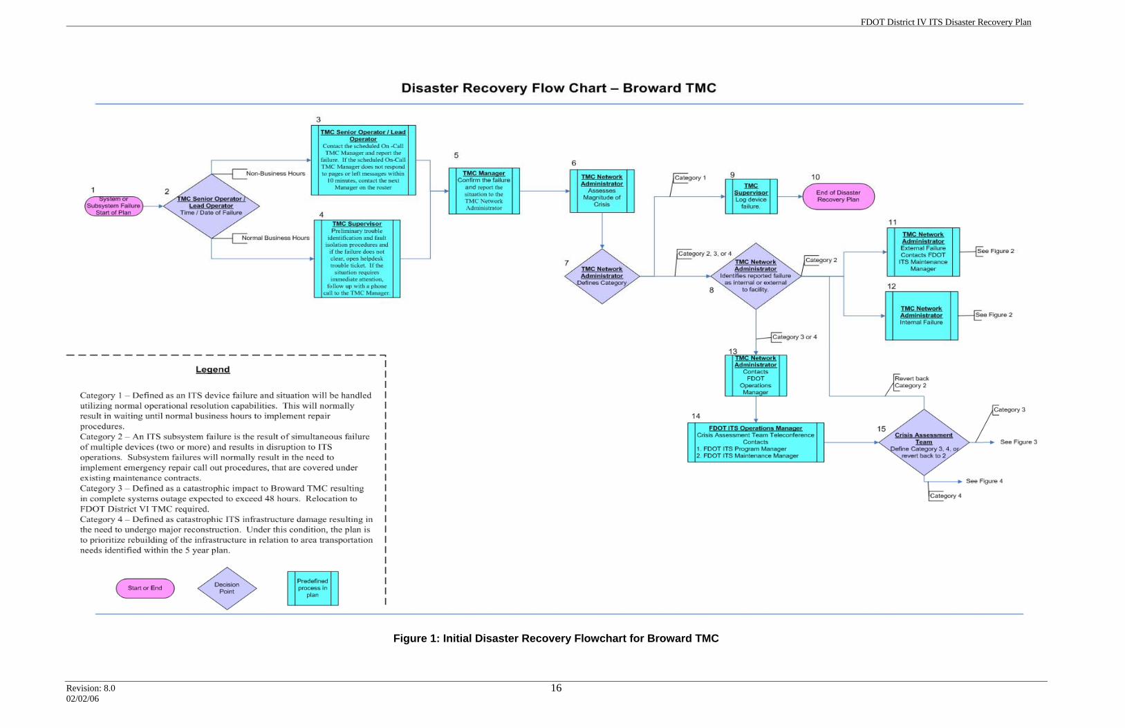
2.5 Disaster Recovery Plan Flowchart In order to facilitate the disaster recovery declaration process, a disaster recovery plan flowchart has been developed to guide emergency operations in the Broward TMC. The flowchart is depicted in figures 1 through 4. The following sections provide a brief description of the functions represented by each box in the figures.
2.5.1 Description of Figure 1 Listed below is a description of the information boxes in figure 1.
1. System Failure – Start of disaster plan. 2. Generally, the TMC operators on duty at the TMC will be the first
individuals to identify a disaster event. 3. If the emergency event occurs during non-business hours, the senior
TMC operator on duty will (a) gather initial information as to which field devices, subsystems, or systems are not in operation, and (b) contact the on-call TMC Manager to report the failure.
4. If the emergency event occurs during business hours, the TMC Supervisor will perform preliminary trouble identification and fault isolation procedures. If the failure does not clear within minutes, the supervisor will open a help-desk trouble ticket.
5. The TMC Manager will confirm the failure and notify the TMC IT Network Manager of the situation.
6. The TMC IT Network Manager is responsible for assessing the magnitude of the crisis.
FDOT District IV ITS Disaster Recovery Plan
Revision: 8.0 02/02/06
11
7. The TMC IT Network Manager defines the appropriate category of failure. 8. The TMC IT Network Manager identifies the failure as either internal or
external to the facility. 9. For single ITS device failures, the TMC IT Network Manager will assign a
Category 1 failure designation and log the device failure. Category 1 failures are defined as non-critical, and are to be handled within the normal operational resolution capabilities.
10. No further actions are required for Category 1 failures; this marks the end of operations under the disaster recovery plan.
11. For external failures, the TMC IT Network Manager contacts and reports the failure to the FDOT ITS Maintenance Manager.
12. For internal failures, the TMC IT Network Manager, or designee, will handle the situation themselves.
13. For Category 3 or 4 failures, the TMC IT Network Manager will contact the FDOT ITS Operations Manager.
14. The FDOT ITS Operations Manager will initiate a conference with the crisis assessment team and contact the FDOT ITS Program Manager and the FDOT ITS Maintenance Manager.
15. The crisis assessment team will designate the failure event as a Category 3 or 4, or they may decide to reclassify the event as a Category 2 failure. The crisis assessment team will exercise their own judgment in assessing the event.
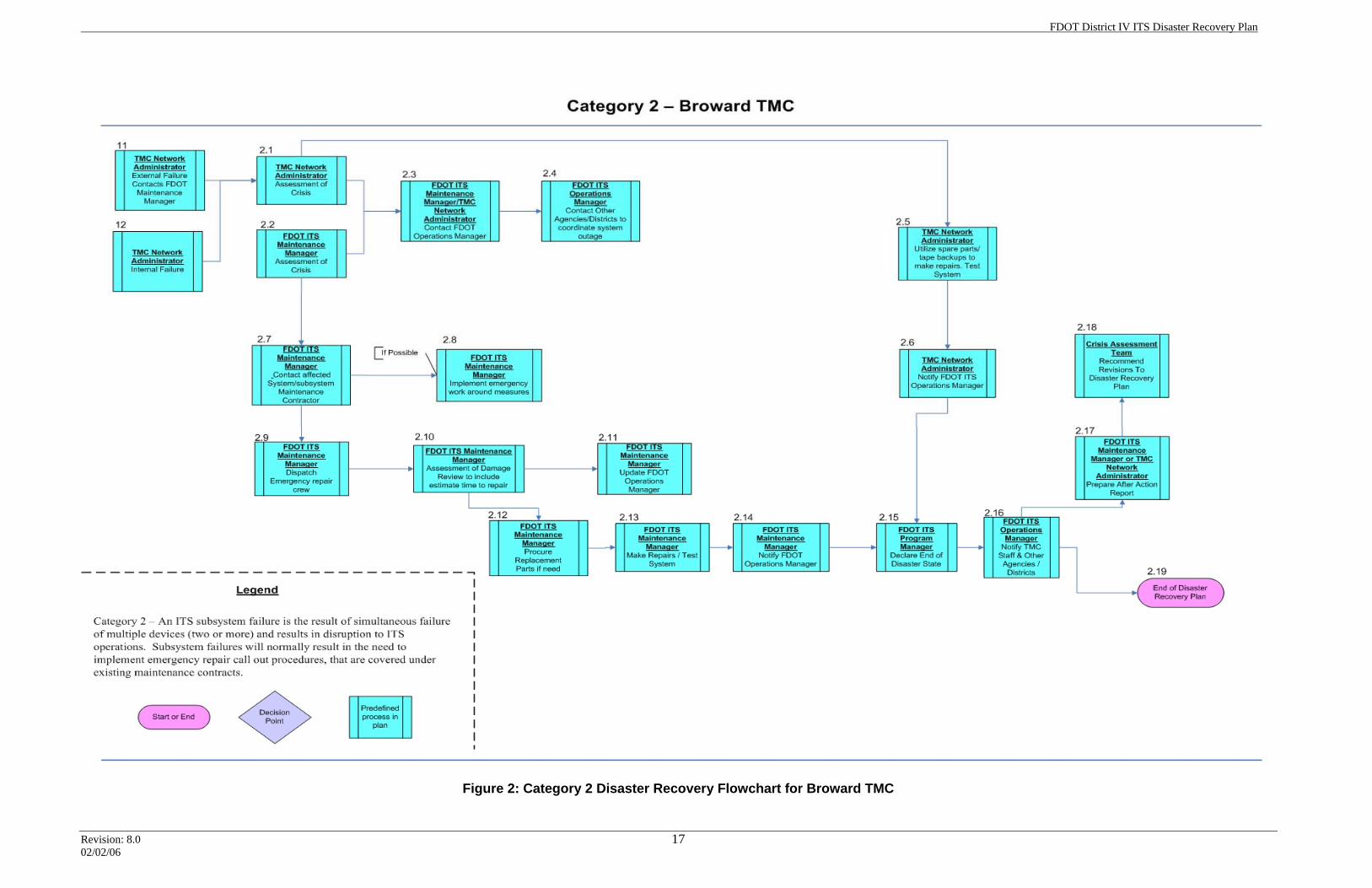
2.5.2 Description of Figure 2 Listed below is a description of the information boxes in figure 2.
2.1 This further defines the actions to be followed during a Category 2 system failure. The TMC IT Network Manager will perform a more technical assessment of the crisis.
2.2 This further defines the actions to be followed during a Category 2 system failure. The FDOT ITS Maintenance Manager will perform a more technical assessment of the crisis.
2.3 After the technical assessment of the crisis is completed, the TMC IT Network Manager or the FDOT ITS Maintenance Manager will brief the FDOT ITS Operations Manager on the current situation.
2.4 The FDOT ITS Operations Manager will contact the governmental agencies and regional TMCs that are interconnected with the Broward TMC and notify them of system outages and reduced operational status.
2.5 For internal failures, the TMC IT Network Manager will utilize spare parts and/or tape backups to make repairs and test the system.
2.6 For internal failures, after repairs are completed, the TMC IT Network Manager will contact the FDOT ITS Operations Manager and notify him or her of the situation.
FDOT District IV ITS Disaster Recovery Plan
Revision: 8.0 02/02/06
12
2.7 For external failures, the FDOT ITS Maintenance Manager will be responsible for contacting the emergency repair contractor and coordinating the repair procedures.
2.8 The FDOT ITS Maintenance Manager will implement emergency workaround measures, if possible bringing the system on line and isolating the failure to a single location.
2.9 The FDOT ITS Maintenance Manager will be responsible for dispatching and coordinating emergency repair crews.
2.10 The FDOT ITS Maintenance Manager will conduct a damage review with the emergency repair contractors.
2.11 The FDOT ITS maintenance Manager will communicate the estimated time to repair or restore full operational capabilities to the FDOT ITS Operations Manager.
2.12 The FDOT ITS Maintenance Manager will coordinate the procurement of replacement parts.
2.13 The FDOT ITS Maintenance Manager will effect repairs and test the system.
2.14 The FDOT ITS Maintenance Manager will notify the FDOT ITS Operations Manager as soon as the system is tested and deemed to be restored to full operational capacity.
2.15 The FDOT ITS Operations Manager will contact the FDOT ITS Program Manager to advise that the situation has been resolved. The FDOT ITS Program Manager will declare the end of the disaster state.
2.16 The FDOT ITS Operations Manager will notify the TMC staff, any governmental agencies, and regional TMC partners that were initially contacted.
2.17 The FDOT Maintenance Manager or the TMC IT Network Manager will prepare the after-action report detailing the circumstances and events of the disaster.
2.18 The crisis assessment team will review the report and recommend any needed revisions to the disaster recovery plan.
2.19 This step is the final activity required under the disaster recovery plan.
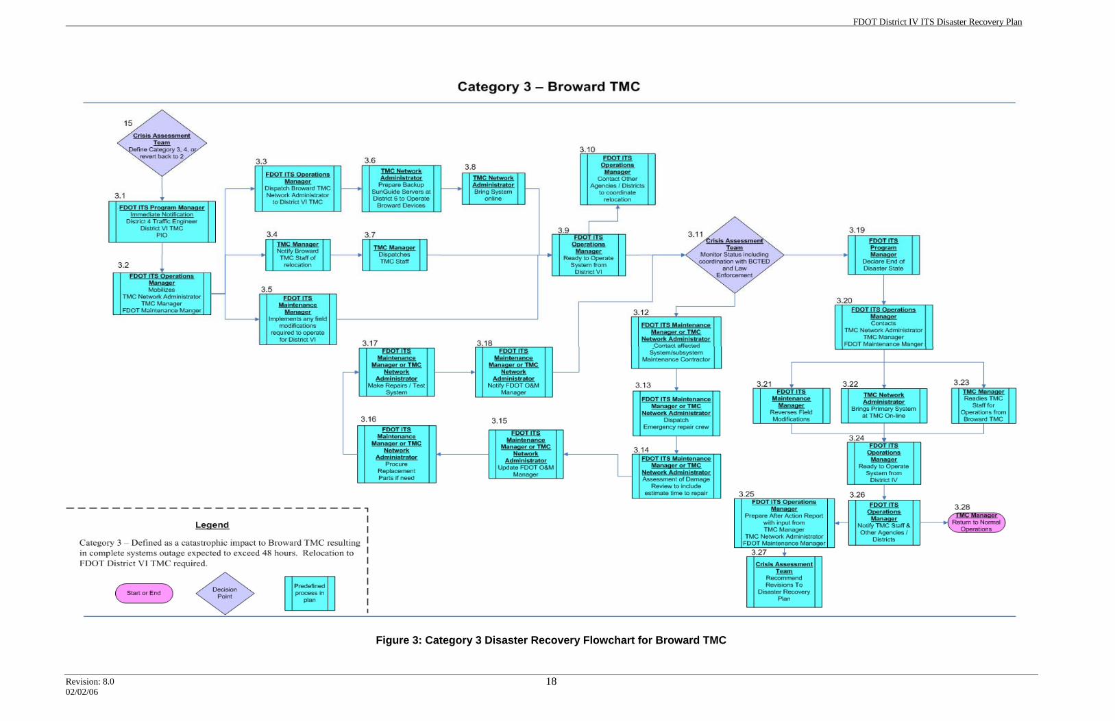
2.5.3 Description of Figure 3 Listed below is a description of the information boxes in figure 3.
3.1 Further defines the actions to be followed during a Category 3 failure. This failure requires deployment to the contingency site. The FDOT ITS Program Manager issues immediate notifications to the District IV Traffic Operations Engineer, the District VI TMC, and the PIO.
3.2 The FDOT ITS Operations Manager mobilizes the TMC IT Network Manager, the TMC Manager, and the FDOT ITS Maintenance Manager.
FDOT District IV ITS Disaster Recovery Plan
Revision: 8.0 02/02/06
13
3.3 The FDOT ITS Operations Manager dispatches the TMC IT Network Manager to the District VI TMC.
3.4 The TMC Manager prepares staff to move operations to District VI TMC. 3.5 The FDOT ITS Maintenance Manager implements any field modifications
required to operate at the District VI TMC. 3.6 The IT Network Manager prepares the pre-deployed SunGuide servers
for primary operation. 3.7 The TMC Manager notifies staff of the relocation, and dispatches two or
more operators to District VI TMC. 3.8 The IT Network Manager brings systems on line. 3.9 Once the systems at the District VI TMC are verified to be on line and
functioning, and the operators have arrived, the FDOT ITS Operations Manager will begin operations from the contingency location.
3.10 The FDOT ITS Operations Manager will contact other governmental agencies and regional TMCs that are interconnected with the Broward TMC and notify them of system outages and the deployment to the contingency site.
3.11 The crisis assessment team will monitor the situation status. If the crisis is related to the facility, the crisis assessment team will coordinate with the BCTED or law enforcement as appropriate.
3.12 If the crisis is related to systems failure, the FDOT ITS Maintenance Manager (failures external to the TMC) or the TMC IT Network Manager (failures internal to the TMC) will contact the maintenance contractors.
3.13 The FDOT ITS Maintenance Manager (failures external to the TMC) or the TMC IT Network Manager (failures internal to the TMC) is responsible for dispatching emergency repair crews.
3.14 The FDOT ITS Maintenance Manager or the TMC I Network Manager, in coordination with the maintenance contractors, will assess the damage and develop an estimated time to repair.
3.15 The FDOT ITS Maintenance Manager (failures external to the TMC) or the TMC IT Network Manager (failures internal to the TMC) will update the FDOT ITS Operations Manager.
3.16 The FDOT ITS Maintenance Manager or the TMC IT Network Manager will procure replacement parts.
3.17 The FDOT ITS Maintenance Manager or TMC IT Network Manager will make repairs and test the system.
3.18 The FDOT ITS Maintenance Manager or TMC IT Network Manager will update the FDOT ITS Operations Manager. The crisis assessment team will monitor the situation and, when ready, recommend an end of disaster status.
3.19 The FDOT ITS Program Manager will declare “end of disaster” status.
FDOT District IV ITS Disaster Recovery Plan
Revision: 8.0 02/02/06
14
3.20 The FDOT ITS Operations Manager relays the status change to the TMC IT Network Manager, the TMC Manager, and the FDOT ITS Maintenance Manager.
3.21 The FDOT ITS Maintenance Manager reverses any field modifications. 3.22 The TMC IT Network Manager brings the primary system at Broward
TMC on line. 3.23 The TMC Manager readies staff for resumption of operations from the
Broward TMC. 3.24 Once the system is ready for operations, the FDOT ITS Operations
Manager will resume primary operations from the Broward TMC. 3.25 The FDOT ITS Operations Manager will be responsible for notifying the
TMC staff, any government agencies, and regional TMC partners that were initially contacted about the system failure.
3.26 The FDOT ITS Operations Manager will coordinate the preparation of an after-action report (with input from the TMC Manager, the IT Network Manager, and the FDOT ITS Maintenance Manager) detailing the circumstances and events of the disaster.
3.27 The crisis assessment team will review the report and recommend any needed revisions to the disaster recovery plan.
3.28 The TMC Manager returns the facility to normal operations.
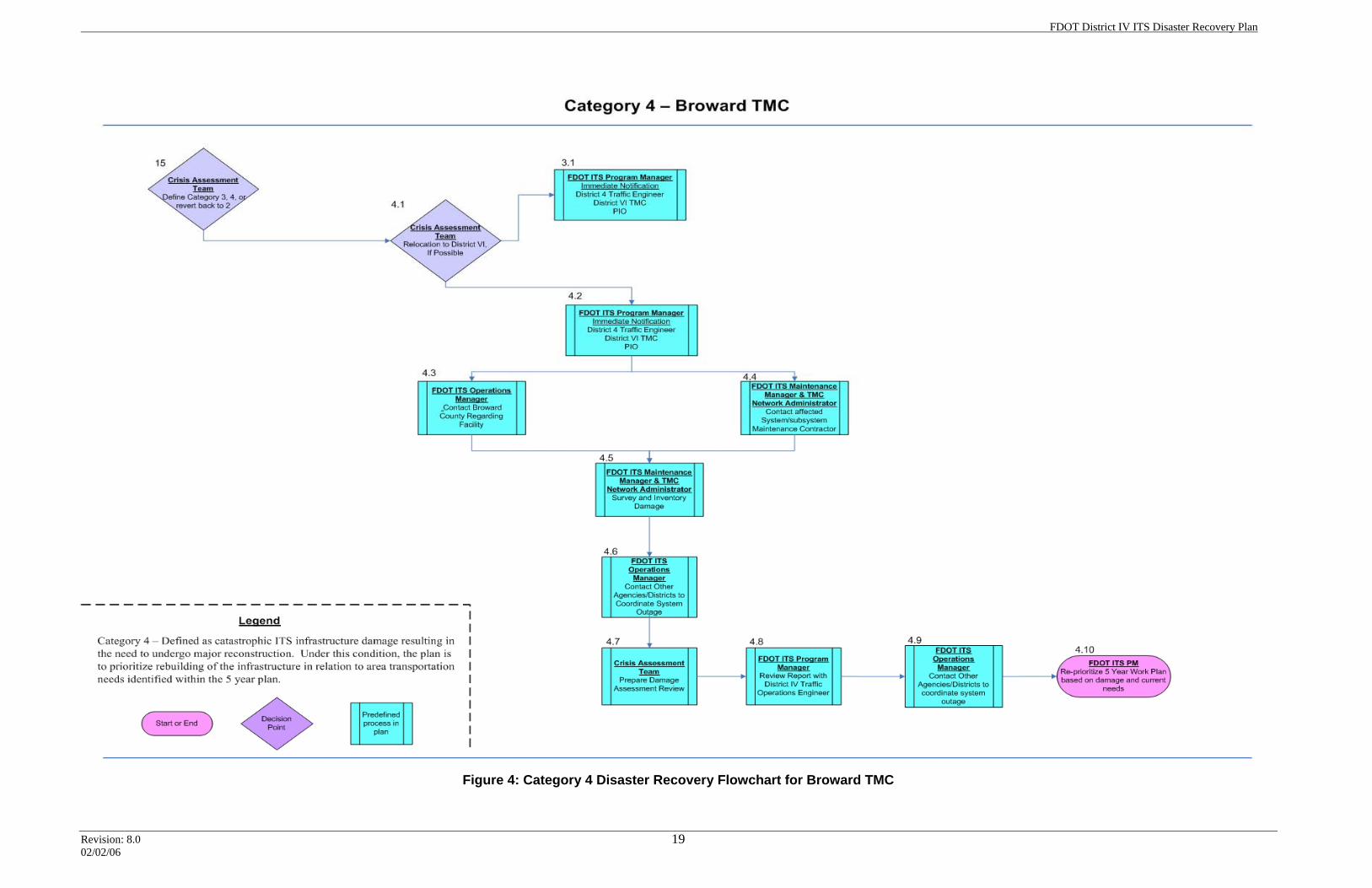
2.5.4 Description of Figure 4 Listed below is a description of the information boxes in figure 4.
4.1 This diagram further defines the actions to be followed during a Category 4 failure. This failure is reserved for a catastrophic event that results in massive damage to the ITS infrastructure within District IV. If possible, the crisis assessment team will relocate to District VI for operations (see relocation process). The FDOT ITS Maintenance Manager or the TMC IT Network Manager will effect repairs and test the system.
4.2 If relocation is not possible, the FDOT ITS Program Manager will notify the District 4 Traffic Operations Engineer, the District VI TMC, and the PIO.
4.3 The FDOT ITS Operations Manager will contact BCTED regarding issues with the Broward TMC facility.
4.4 The FDOT ITS Maintenance Manager and TMC IT Network Manager will contact affected systems maintenance contractors.
4.5 The FDOT ITS Maintenance Manager and the TMC IT Network Manager will coordinate a survey and inventory of the damage with the maintenance contractors, and update the FDOT ITS Operations Manager.
FDOT District IV ITS Disaster Recovery Plan
Revision: 8.0 02/02/06
15
4.6 The Operations Manager will coordinate with any affected governmental agencies and regional TMC partners.
4.7 The crisis assessment team will prepare a damage assessment review report.
4.8 The FDOT ITS Program Manager will review the report with the District IV Traffic Operations Engineer.
4.9 The Operations Manager will continue coordination with any affected governmental agencies and regional TMC partners.
4.10 The FDOT ITS Program Manager will reprioritize the five-year work plan based on the damage assessment review report and current needs.
FDOT District IV ITS Disaster Recovery Plan
Revision: 8.0 02/02/06
16
Figure 1: Initial Disaster Recovery Flowchart for Broward TMC
FDOT District IV ITS Disaster Recovery Plan
Revision: 8.0 02/02/06
17
Figure 2: Category 2 Disaster Recovery Flowchart for Broward TMC
FDOT District IV ITS Disaster Recovery Plan
Revision: 8.0 02/02/06
18
Figure 3: Category 3 Disaster Recovery Flowchart for Broward TMC
FDOT District IV ITS Disaster Recovery Plan
Revision: 8.0 02/02/06
19
Figure 4: Category 4 Disaster Recovery Flowchart for Broward TMC
FDOT District IV ITS Disaster Recovery Plan
Revision: 8.0 02/02/06
20
Section 3.0: Palm Beach ITMS Plan
3.1 Overview of ITMS Infrastructure The Palm Beach ITMS is a 24 × 7 × 365 TMC. The West Palm Beach–based center provides incident management along the 45-mile corridor of I-95 between Boca Raton and Jupiter, using a network of portable ITS equipment that can be moved as the nine-year reconstruction project is completed. The ITMS utilizes a series of 30 SmartZones™ that are controlled remotely from the TMC; they are equipped to provide CCTV cameras, speed data, and portable DMSs. Additional DMSs are adjacent to I-95 along arterial routes to provide advanced warning of adverse conditions. The TMC manages the Road Ranger service patrol and regional incident information between FDOT, Florida Highway Patrol, Palm Beach County Traffic Engineering, and the City of Boca Raton Traffic Engineering.
3.1.1 TMC Facility The TMC facility is a one-story building located at 2200 Centrepark West Drive, Suite 200, West Palm Beach. The structure is load-bearing masonry with filled cells and bond beams. Roofing membrane and tapered insulation overlie metal decking that is attached to steel bar joists. The windows are ‘‘Storefront’’ Dade County window systems rated to withstand the impact of a 2' × 4' object flying at 140 miles per hour.
3.1.2 Power System The center operates on FPL commercial service, with a transfer switch that shifts automatically to a 60 kW Cummins diesel generator when there is a power failure. The 500-gallon fuel tank has the capacity to sustain 24 × 7 operations for an estimated 6–8 days.
3.1.3 Computer Servers The following computer servers support TMC operations:
• MIST™ (Management Information System for Transportation)
• Four rack-mount servers with supporting accessories
• Local intranet network server
• Windows 2000 server for local network operations and data storage at a remote PB Farradyne office in Fort Lauderdale
• Radiant Web server
• Windows 2000 server to host the ITMS Web site
• AVI video wall and server
FDOT District IV ITS Disaster Recovery Plan
Revision: 8.0 02/02/06
21
3.1.4 Workstations • Operators
o The six workstations operate in a client server environment.
• Other Workstations o There is one workstation for the systems administrator, one for the
supervisor, and one for the receptionist.
• Laptops o There are two laptops in service; one for the field engineer, and one
for the operations manager.
• Printers o Lanier copy/printer/fax (networked) o HP laser printer (networked)
3.1.5 Network Equipment • Bell South T1 devices (14)
• Cisco switches and firewalls
• Palm Beach County Traffic Engineering network switch
• Boca Raton Traffic Engineering network switch
• Palm Beach video camera networking equipment
• Broward network switch
3.1.6 Telephones • Internal Siemens digital phone system linked to BellSouth through a T1 line
• Three Nextel cellular phones
• Emergency fixed or portable satellite phone (future plan)
3.1.7 Radios • FHP Troop L and K monitor-only 800 MHz trunk radio
• Bearcat public service communication scanner
• NOAA weather radio
3.1.8 ADT Security System • Card access; magnetic release lock
• Software on administrative assistant’s computer, backed up with network server
FDOT District IV ITS Disaster Recovery Plan
Revision: 8.0 02/02/06
22
• Four exterior CCTVs
• Three card readers for controlling door access
3.1.9 Field Equipment • Portable SmartZones™ (CCTV, radar speed detector, DMS)
o Units deployed in the field: a maximum of 30. o Two additional units (spares) are stored at the contractor’s facility in
West Palm Beach.
• Portable DMS trailers o Trailers in field locations: 44 o Trailers stored at the contractor’s facility in West Palm Beach: 8
• Twelve Hub Sites o PB ITMS field devices are deployed along the 45-mile I-95 corridor in
Palm Beach County. Supplemental portable DMS trailers are strategically located along major arterial/alternate routes. Each portable device is connected by wireless communications (802.1b or GPRS) to the ITMS TMC in West Palm Beach. MasTec NA is responsible for operations and maintenance of all field devices. Future permanent DMS are planned along arterial routes.
3.1.10 Communication with Road Rangers Palm Beach ITMS manages the fleet of free road service patrol vehicles along I-95 in Palm Beach County. Two-way “walkie-talkie” radio communication is established with the “direct connect” feature of the Sprint/Nextel wireless network. A proposed UHF radio system is being reviewed by the FDOT to replace the current Sprint/Nextel system. A third alternative is the Verizon Wireless phone “push-to-talk” feature, which may be implemented in 2006.
3.1.11 Center-to-Center Communications PB ITMS is directly linked to the Broward TMC via a high bandwidth Ethernet line provided by Bell South. This service allows for CCTV video and data exchange. Five ITMS CCTV feeds are sent to Broward. Future plans are to secure the network and exchange video and data from each respective center. Telephone communications, e-mail, and text-message paging are exchanged between ITMS and the following communications centers: the Broward SMART SunGuide TMC, Florida’s Turnpike/Pompano Beach TMC, the SunGuide Miami-Dade TMC, the Palm Beach County Traffic Engineering control center, the Palm Beach County Emergency Operations Center, the Florida Highway Patrol Lake Worth Regional Communications Center, and the City of Boca Raton Traffic Engineering facility.
FDOT District IV ITS Disaster Recovery Plan
Revision: 8.0 02/02/06
23
3.2 ITMS Plan Implementation This section specifies the key assumptions that went into the development of the plan. It also provides a plan overview and details the initial components when the plan is initiated. Further, it contains a disaster recovery flowchart that provides a visual decision-making flow process to help management implement the plan.
3.2.1 Overview The disaster recovery plan addresses the consequences of disaster events, and not the plethora of potential individual events themselves. From the perspective of Palm Beach ITMS operations, any given disaster event has four possible outcomes. Those four outcomes are defined as categories, and each category is associated with predefined actions that facilitate rapid management decision making. Dividing disaster events into predefined categories helps management quickly determine the appropriate response. The response options are tailored to match the severity of the event. The basic options escalate through the following sequence: (a) working within normal operational resolution capabilities, (b) deploying emergency maintenance repair crews, (c) relocating operations to a contingency site, and (d) adjusting the five-year work plan to rebuild the ITS infrastructure following catastrophic damage.
3.2.2 Key Assumptions The disaster recovery plan defines a disaster as "an occurrence inflicting widespread destruction and/or distress upon the District IV TMC facilities, ITS systems, or infrastructure." For the purposes of this document, this means that the facilities, computing resources, or major components thereof are deemed unavailable for operations. This section contains some general assumptions, but does not include all special situations that can occur. Any special decisions that are required for situations not covered in this plan will be made by the senior FDOT ITS management members at the time of the incident. Once a disaster event has occurred and this plan has been declared in effect, the plan, duties, and responsibilities will remain in effect until the incident is resolved and proper FDOT authorities are notified. Invoking this plan implies that a recovery operation has begun and will continue with top priority until workable ITS operations has been reestablished.
3.3 Initial Failure Under most circumstances, initial failures will be noticed by the ITMS operators on duty inside the control room. Depending on the time period when the failure is identified, the ITMS operators will initiate one of the following two actions:
1. Normal Business Hours – During normal business hours, the senior TMC Operator/Lead Operator will notify the TMC Supervisor on duty at that time. The TMC Supervisor will perform preliminary trouble identification and fault-
FDOT District IV ITS Disaster Recovery Plan
Revision: 8.0 02/02/06
24
isolation procedures. If the failure does not clear, the supervisor will report the situation to the TMC Manager.
2. Non-business Hours – During evenings, weekends, and holidays, the senior TMC Operator/Lead Operator will contact the scheduled TMC Manager and report the failure. If the scheduled TMC Manager does not respond to pages or voice messages within 10 minutes, the next TMC Manager on the roster is to be contacted. This notification process will continue until all TMC managers have been contacted, or until a manager responds.
Under certain circumstances the news media may come to the ITMS unannounced, requesting information or statements during the initial failure process. If so, the TMC operators will follow the ITMS standard operating procedure for handling news media inquiries.
3.4 Assessing the Magnitude of a Crisis The PB ITMS Project Manager or Operations Manager will be tasked with gathering information on the disaster event and assessing the magnitude of the crisis. If a Category 3 or 4 emergency is needed, they will initiate a conference with the crisis assessment team about the pending crisis in an effort to decide appropriate actions. The conference notification process may take place in person, or contact may be made over the telephone. The crisis assessment team will consist of the following members (in descending chain-of-command order):
a. FDOT ITS Program Manager b. FDOT ITS Operations Manager c. PB ITMS Project Manager d. PB ITMS Operations Manager e. PB ITMS Field Engineer f. Contractor Project Manager for operations & maintenance
This group will discuss and survey the scope of damage in order to assign a Category 3 or 4 disaster classification. Depending on that final classification, the team may formally initiate deployment to the contingency site. Depending on the nature of the crisis, the crisis assessment team may also elect to revert to a Category 2 classification, and initiate the procedures outlined within.
3.4.1 Crisis Designations The following are potential crisis classifications that the crisis assessment team may designate:
• Category 1 – Defined as an ITS device failure with no real impact on ITS operations. For example, a camera, DMS, or video wall element may have failed. A single device failure will be handled utilizing normal operational capabilities for problem resolution. This will normally entail
FDOT District IV ITS Disaster Recovery Plan
Revision: 8.0 02/02/06
25
waiting until normal business hours to implement repair procedures. The presenting problems may still warrant special management attention and user communications. Within this classification, routine management and user communication channels will be utilized.
• Category 2 – Defined as an ITS subsystem failure. An ITS subsystem failure is the result of simultaneous failure of two or more devices, and results in disruption to ITS operations. Subsystems that would warrant a Category 2 designation upon failure are defined as the video wall, the TMC network, MIST™, the T1 communications line, the camera system, or the DMS system. Subsystem failures will normally result in the need to implement emergency repair callout procedures that are covered under existing maintenance contracts.
• Category 3 – Defined as a catastrophic impact to the PB ITMS facility or infrastructure, and resulting in a complete system outage that is expected to exceed 48 hours duration. Such damage might be occasioned by water, smoke, fire, vandalism, terrorism, lightning, or a protracted period of equipment downtime (estimated or actual) that renders a major portion of the facility unusable for more than 48 hours. This category would also apply to communication failures resulting in a systems outage to a significant portion of the ITS field devices, when the outage is expected to exceed 48 hours. Under these circumstances, it is expected that the ITMS facility will cease operations and/or relocate to one of the following facilities based on the magnitude of the impact:
1. Palm Beach County Traffic Engineering in West Palm Beach 2. FDOT District IV Broward TMC in Fort Lauderdale 3. City of Boca Raton Traffic Engineering, Boca Raton 4. FDOT District IV maintenance Forest Hill facility, West Palm Beach
• Category 4 – Defined as catastrophic ITS infrastructure damage resulting in the need for major reconstruction. For events that fall under this classification, the plan is to prioritize rebuilding of the infrastructure to conform to area transportation needs identified within the five-year plan.
3.4.2 Chain of Command/Decision Making The FDOT ITS Program Manager, or designee, has the ultimate responsibility for evaluating and declaring the disaster classification, and for assessing the organizational impact on the enterprise and its ongoing operations. In the FDOT ITS Program Manager’s absence, the FDOT ITS Operations Manager will be responsible for taking these actions.
3.4.3 Coordinating with Other Agencies or Districts As the FDOT TMCs around the state become increasingly interconnected, a TMC experiencing a system outage will need to advise other TMCs (its regional partners) of disaster events. During a declared disaster recovery plan event, a
FDOT District IV ITS Disaster Recovery Plan
Revision: 8.0 02/02/06
26
general “For Your Information” (FYI) notification may be communicated to the TMC user community. The TMC Manager, or the on-call manager, will decide if an FYI notification is warranted, and which agencies may be contacted. The TMC Manager will follow the standard operational procedures (SOP) for agency contacts and notifications. This notification is a simple statement that the Palm Beach ITMS is experiencing a system outage, and that the duration is either known (xx hours to repair) or unknown.
3.4.4 Procedures for Communicating with the News Media All press releases and media interviews about the crisis, its impact on TMC operations, related recovery operations, the current status of recovery, estimates of damage, and the outlook for future operations will be conducted through the FDOT District IV PIO. All such questions and inquiries are to be directed to Barbara Kelleher; her phone number is (954) 777-4090. Comments about the crisis or disaster will not be offered to reporters or other media representatives by any TMC staff members. Any approaches or questions from the media should be directed to the FDOT PIO. Even when comments are requested concerning various publicly known aspects of the crisis, or previously announced details concerning the crisis, the questioner should be directed to the FDOT PIO. News media access to TMC facilities or personnel, and the dissemination of announcements concerning TMC operations, will be handled through the FDOT PIO. This procedure will enable the PIO to control the timing and accuracy of the information being released, project the institutionally sanctioned perspective, and minimize unwarranted speculation and sensationalism. It is possible that the media will come to the Palm Beach ITMS unannounced. If this situation occurs, ITMS management will be contacted and on-site staff should follow ITMS SOPs for media inquiries.
3.5 Staff Roles and Responsibilities All members of the TMC staff have unique roles and responsibilities that pertain to their positions. The key personnel involved in ITMS systems disaster recovery are as follows:
• FDOT ITS Program Manager – Responsible for overall management, coordinating, and planning related to disaster events. Additional responsibilities include communicating situational reports to FDOT District IV management.
• FDOT ITS Operations Manager – Responsible for monitoring all disaster-related events and assessing their impact on ITS operations.
• ITMS Project Manager – Responsible for assessing the magnitude of the crisis, using the information gathered by the ITMS Operations Manager, Field Engineer, or network administrator. The ITMS Project Manager can authorize implementation of Category 1, 2, 3, or 4 disaster recovery procedures. For Category 3 and 4 disasters, the ITMS Operations Manager
FDOT District IV ITS Disaster Recovery Plan
Revision: 8.0 02/02/06
27
must initiate a conference call with the FDOT ITS Program Manager, the FDOT Operations Manager, the FDOT Maintenance Manager, and the ITMS Project Manager. This group will discuss the event and choose an appropriate course of action.
• ITMS Operations Manager – Responsible for assessing the magnitude of the crisis, based on the information gathered by the TMC operators or shift supervisors. The ITMS Operations Manager can implement Category 1 or 2 disaster recovery procedures. For Category 3 and 4 disasters, the ITMS Operations Manager will contact the ITMS Project Manager and participate in the subsequent conference call. The conference call participants will discuss the event and choose an appropriate course of action.
• ITMS Field Engineer – Responsible for ITMS field equipment and communication systems. Will work in conjunction with the ITMS Project Manager and the ITMS Operations Manager to assess failures and restore operations.
• ITMS Network Administrator – Responsible for internal ITMS computer and network systems. Will work in conjunction with the ITMS Project Manager and the ITMS Operations Manager to assess failures and restore normal operations.
• AM and PM Shift Supervisors – Responsible for recognizing the initial failure during normal hours, gathering the essential information, and reporting the issue to the ITMS Operations Manager.
• Systems Operator I, II, III – Responsible for system operation and monitoring inside the control center. The operators will generally be the first individuals to notice any failures. They are responsible for contacting the AM Shift Supervisor, the PM Shift Supervisor, or the TMC Operations Manager, as appropriate.
3.6 Employee Vacation Status In the event of an implementation of the disaster recovery plan, the policy of the Palm Beach ITMS is to honor previously scheduled employee vacations. All employee vacations already in progress will proceed normally.
3.7 Disaster Recovery Plan Flowchart The Palm Beach ITMS portion of the disaster recovery plan follows the same model as far as processes are concerned, but the key personnel titles are different. The Palm Beach ITMS has developed alternate operational contingency sites at the Boca Raton Traffic Engineering TMC and the Palm Beach Traffic Engineering TMC, deploying remote functioning MIST workstations at these locations. Palm Beach ITMS management, in conjunction with the FDOT ITS Operations Manager, will decide which alternate contingency site will be utilized (depending on the nature and scope of the disaster event). The Palm Beach ITMS part of the disaster recovery plan is defined in detail in section 6.
FDOT District IV ITS Disaster Recovery Plan
Revision: 8.0 02/02/06
28
3.7.1 Figure 5 – Initial Disaster Recovery Flowchart Generally the TMC operators on duty at the ITMS will be the first individuals to detect a disaster event. The disaster event may occur during normal or non-normal business hours. The senior ITMS operator on duty will gather initial information about the field devices, subsystems, or systems that are not in operation and notify the ITMS Operations Manager of the disaster event. The ITMS Operations Manager will assess the magnitude of the crisis with the ITMS Project Manager and initiate a predefined category level response, depending on the event. For single ITS device failures, the on-call manager will assign a Category 1 failure and the senior ITMS operator will log the device failure. Category 1 failures are defined as non-critical, and are to be handled within the normal operational capabilities for problem resolution. For multiple simultaneous ITS device failures defined as a subsystem failure, the ITMS Project Manager will assign a Category 2 failure designation, which by definition requires emergency repair procedures. The ITMS Project Manager will contact the ITMS Operations Manager and the ITMS Field Engineer. For multiple systems failures, or if the TMC facility should need evacuation, the ITMS Project Manager will initiate a conference call with the FDOT Operations Manager, the ITMS Operations Manager, and the ITMS Field Engineer. This management group will discuss the emergency situation and, if needed, relocate operations to one of the contingency sites. The contingency sites have been identified as the Palm Beach Traffic Engineering TMC, the Boca Raton Traffic Engineering TMC, and the FDOT District IV Broward TMC. Depending on the nature of the emergency and the expected duration, the management team may decide to reclassify the event as a Category 2 situation and proceed from there.
3.7.2 Figure 6 – Category 2 Disaster Recovery Flowchart The disaster recovery flowchart further defines the actions to be followed during a Category 2 failure. The ITMS on-call manager will contact the ITMS Operations Manager, the IT Engineer, and the Field Engineer whenever there is a disruption to one or more subsystems and emergency repair is required. The ITMS Operations Manager will coordinate backup operations activities and will notify the ITMS Project Manager of the problem. Based on the type of problem, the IT Engineer and/or the Field Engineer will contact the maintenance contractor for the affected system or subsystem. The engineer(s) will dispatch emergency repair crews to assess the damage and interact with vendors to coordinate hardware salvage, repair, or replacement. More specifically, the IT Engineer will address issues with communications and connectivity, and the Field Engineer will ensure that contractors perform clean-up and restoration activities. The ITMS IT or Field Engineer will work with the emergency repair contractors to assess the damage, and notify the ITMS Project Manager and the ITMS Operations Manager as to the estimated time to repair and restore full operational
FDOT District IV ITS Disaster Recovery Plan
Revision: 8.0 02/02/06
29
capabilities. The ITMS Project Manager will then notify the FDOT ITS Operations Manager of the estimated repair time. The ITMS Project Manager and FDOT ITS Operations Manager will continue to communicate relevant issues throughout the disaster recovery process, until the FDOT ITS Operations Manager declares the end of the disaster state. The FDOT ITS Operations Manager, with continuous input from the ITMS Project Manager, will keep the FDOT ITS Program Manager updated throughout the disaster process. The ITMS Project Manager will then notify the ITMS Operations Manager of the declared end of the disaster state. The ITMS Operations Manager will notify the ITMS staff and coordinate the return to normal operations. Additionally, the ITMS Operations Manager will coordinate the preparation of an after-action report detailing the circumstances and events of the disaster, and will recommend any necessary revisions to the disaster recovery plan. After review, the ITMS Project Manager will issue suitable revisions to the disaster plan.
3.7.3 Figure 7 – Category 3 Disaster Recovery Flowchart The disaster recovery flowchart further defines the actions to be followed during a Category 3 failure. This failure requires deployment to the contingency site. The ITMS Project Manager issues immediate notifications to the FDOT ITS Operations Manager and the District 4 ITS Program Manager. The ITMS Project Manager then notifies the ITMS Operations Manager to prepare for staff relocation, and dispatches the ITMS Network Administrator to the contingency site to prepare backup MIST™ servers for continued operation. The ITMS Operations Manager notifies the staff of the relocation, and dispatches two or more operators to the contingency site. The ITMS Operations Manager will also contact other governmental agencies and regional TMCs that are interconnected with the Palm Beach ITMS to notify them of system outages and the pending deployment to the contingency site. Once the backup systems at the contingency site are verified to be on line and functioning, and the operators have arrived, the ITMS Operations Manager will begin operations from the contingency location. The Network Administrator must prepare the MIST™ servers at the contingency site for primary operation, and bring the system on line. During the above process, the ITMS Field Engineer will contact the emergency repair contractor, conduct a damage assessment review, and prepare a damage assessment and repair report. The ITMS Field Engineer will give the report to the ITMS Project Manager, who will then distribute it to the FDOT ITS Operations Manager. The ITMS Operations Manager will contact the other governmental agencies and regional TMCs and provide suitable updates. The ITMS Field Engineer will coordinate the procurement of replacement parts, effect repairs, and test the system. Once the system is tested and deemed to be restored to full operational capacity, the ITMS Field Engineer will notify the ITMS
FDOT District IV ITS Disaster Recovery Plan
Revision: 8.0 02/02/06
30
Project Manager, who will then notify the FDOT ITS Operations Manager, the ITMS Operations Manager, and the ITMS Network Administrator. The ITMS Network Administrator will ready the primary MIST™ servers for primary operation and bring the systems on line at the Palm Beach ITMS. The ITMS Operations Manager will have operators positioned at the Palm Beach ITMS to be ready to resume normal operation. Once normal operational capability is confirmed, the ITMS Operations Manager will recall the operators from the contingency site. After normal operations are restored, the FDOT ITS Operations Manager will be responsible for declaring an end to the disaster state. At this point in the process, the ITMS Operations Manager will be responsible for notifying the TMC staff, governmental agencies, and regional TMC partners that were initially contacted about the crisis. The ITMS Operations Manager will also coordinate the preparation of an after-action report detailing the circumstances and events of the disaster, and recommend any appropriate revisions to the disaster recovery plan.
3.7.4 Figure 8 – Category 4 Disaster Recovery Flowchart The disaster recovery flowchart further defines the actions to be followed during a Category 4 failure. This failure category is reserved for a catastrophic event that results in massive damage to the ITS infrastructure within District IV. When a Category 4 event occurs, the ITMS Project Manager will contact the ITMS Systems Engineer, the ITMS Field Engineer, and the Project Administrator. The ITMS Field Engineer will conduct an assessment of damage review, contact the emergency maintenance contractor, and prepare a damage assessment and repair report. Based on this report, and if circumstances allow, the ITMS Project Manager will dispatch the ITMS Network Administrator to the Broward TMC to prepare the MIST™ servers (backup or primary) for primary operation and bring the systems on line. The ITMS Operations Manager will notify the staff of the relocation, and dispatch two or more operators to the Broward TMC. The ITMS Operations Manager will contact other governmental agencies and regional TMCs that are interconnected with the Palm Beach ITMS and notify them of system outages and deployment to the contingency site. The ITMS Operations Manager will begin operations from the contingency location once the backup systems at the Broward TMC are verified to be on line and functioning, and the operators have arrived. The FDOT ITS Program Manager will review the damage assessment and repair report with the District 4 Traffic Operations Engineer and make modifications as needed. They will reprioritize the five-year work plan based on current needs and the specific catastrophic damage encountered.
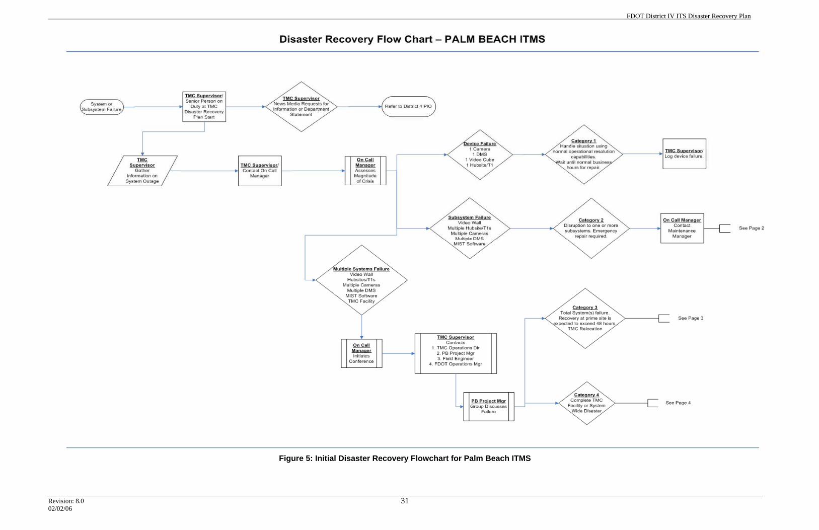
FDOT District IV ITS Disaster Recovery Plan
Revision: 8.0 02/02/06
31
Figure 5: Initial Disaster Recovery Flowchart for Palm Beach ITMS
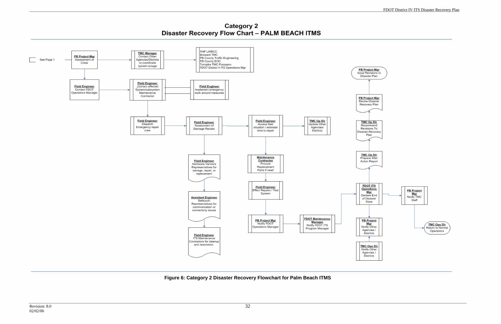
FDOT District IV ITS Disaster Recovery Plan
Revision: 8.0 02/02/06
32
Figure 6: Category 2 Disaster Recovery Flowchart for Palm Beach ITMS
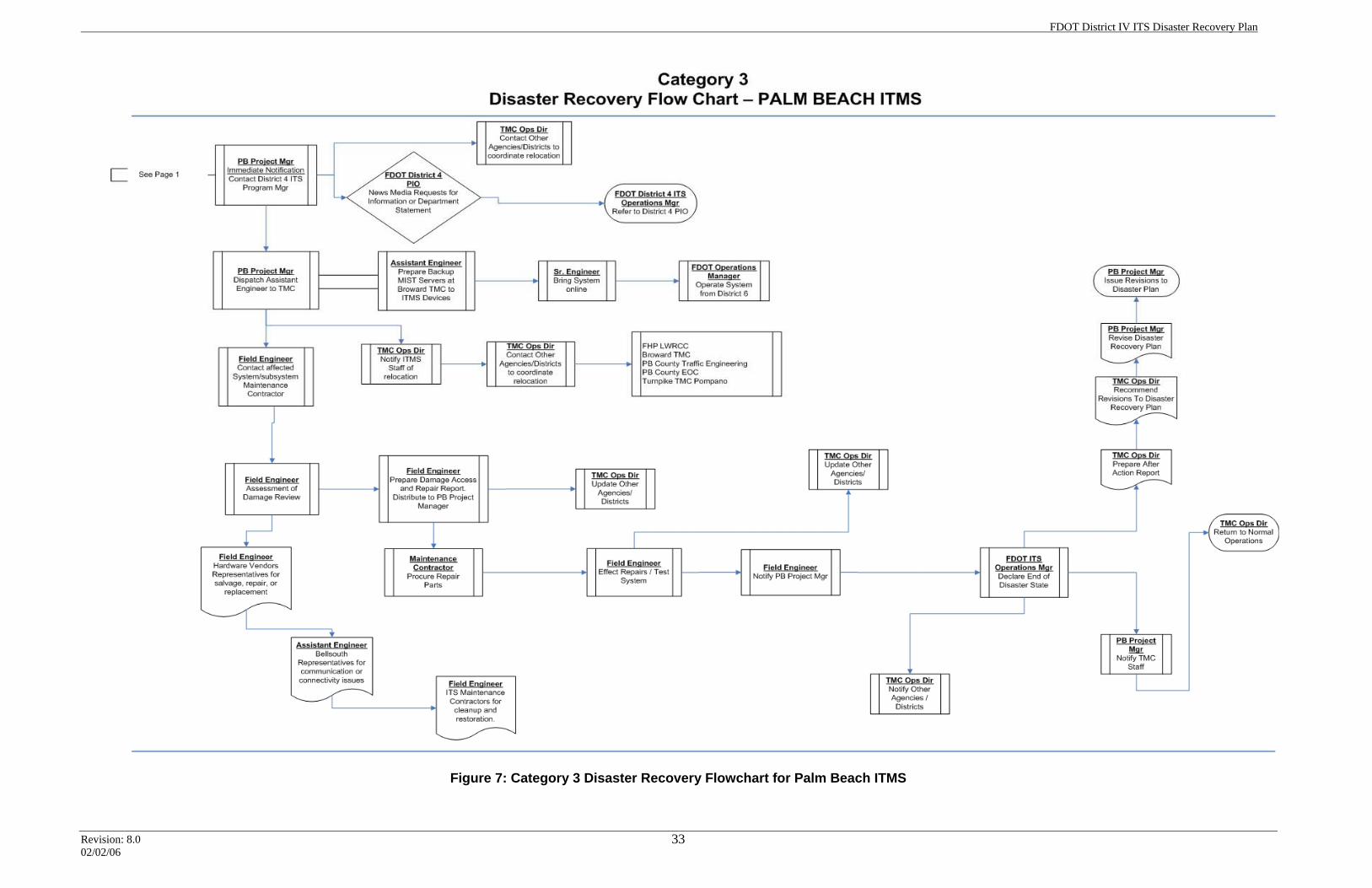
FDOT District IV ITS Disaster Recovery Plan
Revision: 8.0 02/02/06
33
Figure 7: Category 3 Disaster Recovery Flowchart for Palm Beach ITMS
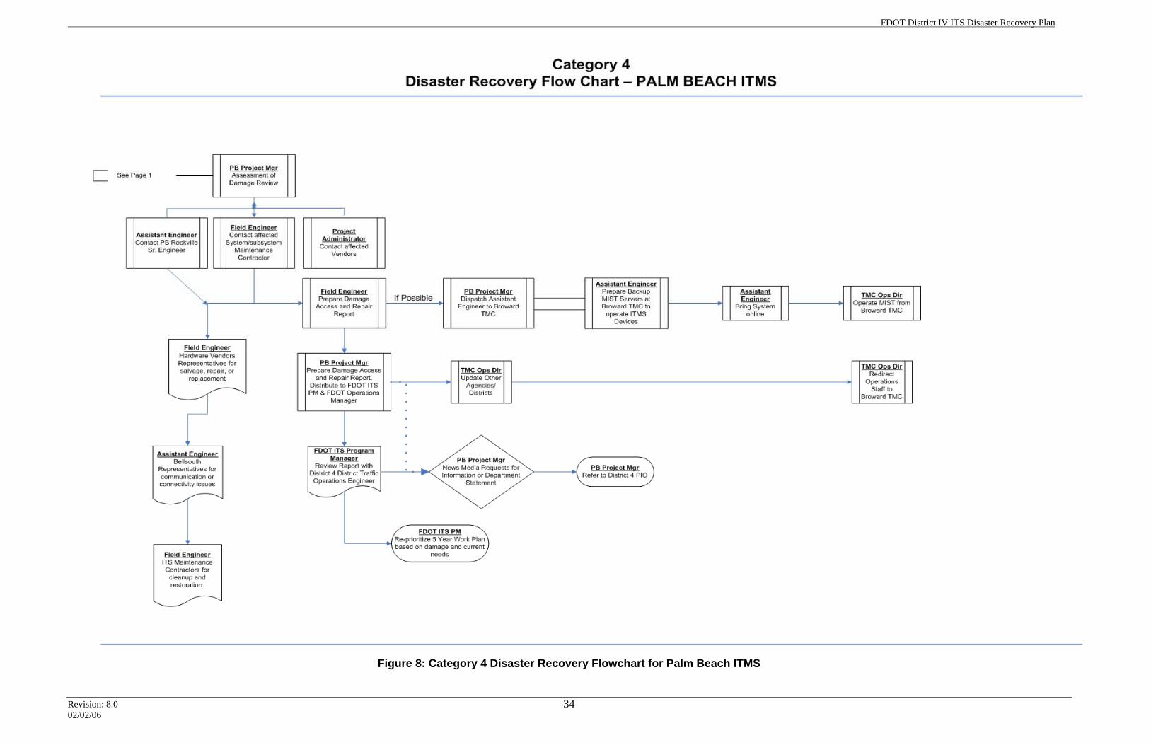
FDOT District IV ITS Disaster Recovery Plan
Revision: 8.0 02/02/06
34
Figure 8: Category 4 Disaster Recovery Flowchart for Palm Beach ITMS
FDOT District IV ITS Disaster Recovery Plan
Revision: 8.0 02/02/06
35
Section 4.0: Plan Administration
4.1 Distribution The disaster recovery plan should be distributed to all senior ITS management staff, and to consultants or contractors providing ITS O&M support services. A copy should also be provided to the FDOT District VI ITS Administrator, as the District VI TMC is considered the District IV contingency site for continuity of operations. At a minimum, the disaster recovery plan administrator will provide plan copies to the following personnel:
• FDOT ITS Program Manager
• FDOT ITS Operations Manager
• FDOT ITS Maintenance Manager
• O&M Maintenance and consulting staff A copy of the disaster recovery plan should be keep at each operator console inside the control center for easy access by the night and weekend shift. A master disaster recovery plan distribution list should be kept by the plan administrator.
4.2 Plan Off-Site Location A copy of the disaster recovery plan will be kept with the tape backups at the Iron Maintain off-site storage location.
4.3 Identification of the Person in Charge of the Plan A critical component of any disaster recovery plan is the need to establish a single point of contact and responsibility for plan updates and associated notifications. The FDOT ITS Program Manager has designated the responsibility for maintaining this disaster recovery plan document to the FDOT ITS Operations Manager. The FDOT ITS Operations Manager may, at his discretion, delegate authority to implement document revisions and notifications to others. Maintenance of the plan includes adherence to the schedule for periodic review of selected provisions, as specified within the plan; monitoring periodic preparedness testing; and maintaining the plan in a constant state of readiness for any potential deployment.
4.4 Training One of the purposes of training is to increase awareness of all parties to the potential threats posed by a disaster, and to acquaint them with the institution's strategies, expectations, procedures, and actions required under such emergency conditions. Staff orientation in the FDOT Broward TMC is specifically geared towards imparting a detailed understanding of the expectations they should meet when a disaster is declared. The disaster recovery plan training should consist of the following type of activities:
• Initial operator training
• Quarterly plan review with senior management
• Annual implementation of parts of the plan
FDOT District IV ITS Disaster Recovery Plan
Revision: 8.0 02/02/06
36
4.4.1 Initial Operator Training All TMC operators should be exposed to the disaster recovery plan concepts and procedures. They should be familiar with the location of the plan, the contact lists, and the reporting hierarchy. New TMC operator hires should be provided exposure during their initial training period. Current TMC operators should be given a training class on the disaster recovery plan concepts and procedures.
4.4.2 Quarterly Plan Review with Senior Management Senior TMC management should meet quarterly to review existing TMC and ITS conditions that may affect the disaster recovery plan. During these quarterly meetings, changes, additions, and modifications to any ITS system that may affect the disaster recovery plan should be identified. Any operational or procedural changes may also be identified, and appropriate disaster recovery plan modifications should be recommended.
FDOT District IV ITS Disaster Recovery Plan
Revision: 8.0 02/02/06
37
Section 5.0: Plan Performance Metrics
Disaster recovery plans have been developed for major IT centers, network operation centers, and computer data centers. Industry-standard disaster recovery plans have one recurring aspect, which is the need to periodically implement the plan on a test basis. These periodic tests provide valuable feedback, enhance the training of staff members involved, and offer a “reality check” of the plan. After such implementation tests, a “lessons learned” assessment is conducted to evaluate selected performance metrics. The disaster recovery plan is then updated to reflect the lessons learned, thereby strengthening the plan’s technical and operational concepts.
5.1 After-Action Report Whenever the disaster recovery plan is implemented, one of the following personnel will be responsible for preparing a “lessons learned” assessment report.
• TMC IT Network Manager – Responsible for lessons learned assessment report related to internal failures.
• FDOT ITS Maintenance Manager - Responsible for lessons learned assessment report related to external failures.
• FDOT ITS Operations Manager - Responsible for lessons learned assessment report related to operational or organizational failures.
The report will document the circumstances surrounding the primary event failure; the personnel involved; the date/time of all major decisions; any equipment needed or utilized; and the length of outages for any systems or subsystems. The lessons-learned assessment will measure critical factors such as response time, availability of appropriate equipment and tools, and operational downtime. The crisis assessment team will review the assessment report, and allocate appropriate resources to modify the disaster recovery plan.
5.2 Initial Plan Validation Upon plan acceptance, the ITS Operations Manager will schedule a series of implementation drills for each of the plan categories. These drills will validate specific recovery procedures for key applications and infrastructure components. They will also ensure the precise documentation of all recovery activities required in the event of a disaster declaration. Upon concluding the initial drills, a lessons-learned assessment will measure the critical factors such as response time, appropriate equipment and tools available, and operational outage downtime. The lessons-learned assessment report will document the successes and failures of the plan and recommend appropriate changes. The recommendations will be reviewed by the FDOT ITS Operations Manager, and the plan will be modified accordingly.
5.3 Plan Implementation Drills The success of the disaster recovery plan can be measured through the use of carefully observed and documented drills. FDOT District IV ITS management will perform semiannual and annual implementation drills to test the procedures and
FDOT District IV ITS Disaster Recovery Plan
Revision: 8.0 02/02/06
38
staff. Additional implementation drills can be scheduled after new systems are installed or whenever major changes occur in existing systems. An unplanned or surprise implementation drill may also be used to test staff familiarity with the disaster recovery plan.
5.3.1 Semiannual Implementation Drills The ITS Operations Manager will conduct semiannual tests of the disaster recovery plan for Category 1 and 2 emergency events. These tests may be conducted in a scheduled and planned format, or in a surprise format. The scheduled semi-annual emergency events will be conducted in the August and November time-frames. This review and rehearsal process will ensure that the disaster recovery plan is maintained up to date as new systems are brought on line and as changes occur in older systems.
5.3.2 Annual Implementation Drills At least once every 12 months, the disaster recovery plan for Category 3 and 4 disasters will be tested. The scheduled or unscheduled emergency events will be conducted in the May time-frame, prior to the start of hurricane season. This means relocating the FDOT Broward TMC to the FDOT District VI TMC for operations. This will not only test the systems, but also the coordination, personnel callout rosters, and operational issues associated with such an event.
FDOT District IV ITS Disaster Recovery Plan
Revision: 8.0 02/02/06
39
Section 6.0: Broward TMC Hurricane Plan
During the years 2004 and 2005, Florida was subjected to direct strikes from five hurricanes that caused massive property damage, the loss of utility power, and major disruptions to the transportation infrastructure. Each of the hurricanes required governmental agencies to initiate evacuation orders to segments of the population. FDOT Central Office prepared the “Hurricane Response Evaluation and Recommendations” document which identifies priority issues and assigns responsibilities for accomplishing these objectives to the district offices. This section of the document addresses the requirements for the District IV area.
6.1 Scope of the Broward TMC Hurricane Plan The objective of the Broward TMC hurricane plan is to demonstrate compliance with the “Hurricane Response Evaluation and Recommendations” document, and identify operational procedures that will enhance the Broward TMC response during and after hurricanes. Additional objectives of this document are to identify critical ITS devices that are needed to remain in operation following a storm event. The preceding storm seasons demonstrated to the TMC operational staff that most ITS device failures are related to post-storm interruptions of commercial power. This plan identifies critical ITS devices that need to remain in operation to support planned re-entry in the South Florida region, and to support the dissemination of any essential diversion route information. The Florida Department of Transportation District IV Emergency Operation Manual 2005 states that the Department has three basic emergency management responsibilities:
• To develop employee assignments, site-specific responses, and procedures that will minimize disruption and ensure the continuity of Department operations when workplace emergencies occur;
• To respond to local emergencies that, directly or indirectly, have an impact on or disrupt the multimodal transportation system; and
• To respond when state emergencies are declared. This plan specifically designates key Department individuals who are charged to act as focal points to accomplish these obligations.
The Broward TMC hurricane plan does not attempt to change any of the requirements put forth by the above-cited manual, but instead focuses on the steps and procedures that are needed—from an ITS perspective—as a hurricane approaches, strikes, and then moves past the area.
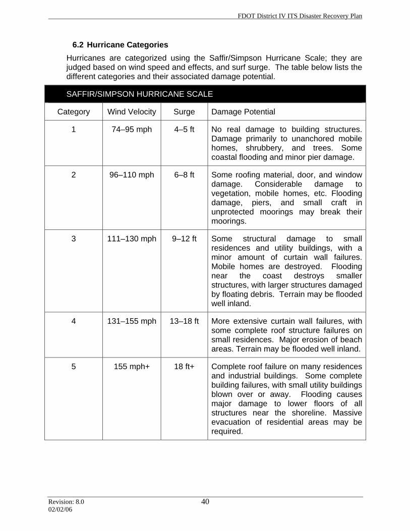
FDOT District IV ITS Disaster Recovery Plan
Revision: 8.0 02/02/06
40
6.2 Hurricane Categories Hurricanes are categorized using the Saffir/Simpson Hurricane Scale; they are judged based on wind speed and effects, and surf surge. The table below lists the different categories and their associated damage potential.
SAFFIR/SIMPSON HURRICANE SCALE
Category Wind Velocity Surge Damage Potential
1 74–95 mph
4–5 ft No real damage to building structures. Damage primarily to unanchored mobile homes, shrubbery, and trees. Some coastal flooding and minor pier damage.
2 96–110 mph 6–8 ft Some roofing material, door, and window damage. Considerable damage to vegetation, mobile homes, etc. Flooding damage, piers, and small craft in unprotected moorings may break their moorings.
3 111–130 mph 9–12 ft Some structural damage to small residences and utility buildings, with a minor amount of curtain wall failures. Mobile homes are destroyed. Flooding near the coast destroys smaller structures, with larger structures damaged by floating debris. Terrain may be flooded well inland.
4 131–155 mph 13–18 ft More extensive curtain wall failures, with some complete roof structure failures on small residences. Major erosion of beach areas. Terrain may be flooded well inland.
5 155 mph+ 18 ft+ Complete roof failure on many residences and industrial buildings. Some complete building failures, with small utility buildings blown over or away. Flooding causes major damage to lower floors of all structures near the shoreline. Massive evacuation of residential areas may be required.
FDOT District IV ITS Disaster Recovery Plan
Revision: 8.0 02/02/06
41
6.3 Compliance The “Hurricane Response Evaluation and Recommendations” document identified the following objectives and responsibilities related to TMC operations:
• Develop a hurricane preparedness plan.
• Establish redundant communication means for Road Ranger, Severe Incident Response Vehicle (SIRV), and TMC operations.
• Place TMC staff at county emergency operations centers (EOCs).
• Develop emergency contracts.
• Train in-house staff to troubleshoot and make repairs to ITS field devices.
• Utilize the hourly counts from locations on major state corridors for monitoring increasing volumes and speed data on the State Highway System (SHS).
• Develop and maintain a spare parts inventory.
• Ensure access to an inventory of portable traffic control devices (Highway Advisory Radio and DMS) prior to the emergency event.
• Obtain and maintain a minimum number of generators to power critical ITS field devices.
• Address hurricane preparedness relating to signal system operations. (This requirement is not applicable to the Broward TMC hurricane plan, and is not addressed within this document.)
These objectives are discussed individually below, in greater detail.
6.3.1 Develop Hurricane Preparedness Plan The FDOT District IV ITS group has developed a Broward TMC hurricane plan that is designed to be in compliance with the “Hurricane Response Evaluation and Recommendations” objectives. That plan is contained within this larger disaster recovery plan. The FDOT Broward TMC facility is shared with the BCTED, and the county is primarily responsible for the maintenance and operation of the building. The BCTED is responsible for preparing the building and its HVAC/mechanical systems for a hurricane event. However, FDOT ITS Operations has a fiduciary obligation to follow up, coordinate, and ensure emergency preparedness has taken place for critical systems (such as generator fueling).
6.3.2 Establish Redundant Communications for Road Rangers, SIRV, and TMC
The “Hurricane Response Evaluation and Recommendations” document identified the requirement for a redundant communication means between the TMC and the Road Ranger vehicles. Starting in July 2005, the FDOT Broward TMC migrated to a private trunk radio system provided by Highland Wireless for primary communication with all Broward County Road Ranger vehicles. As a
FDOT District IV ITS Disaster Recovery Plan
Revision: 8.0 02/02/06
42
backup to the private trunk radio system, the TMC and Road Ranger vehicles will retain their Verizon and Nextel cellular phones. Hurricane Katrina, which struck the District IV area in August 2005, uncovered a weakness in the Highland Wireless private trunk radio system, one that resulted in a storm-related loss of communications. This weakness in the Highland Wireless private trunk radio system is addressed through the installation of a backup Highland Wireless 470 MHz private radio transmittal site. The backup site consists of two 100-watt transmitter sites located on FDOT property. The first site is at the Broward TMC, and the other is at the FDOT maintenance yard near I-595 and the Sawgrass Expressway. This system will be deployed right after a hurricane passes, so that it will not be subject to storm damage. It has the ability to operate for four days without primary power (after UPS and generator failure). The system will be used to communicate between the Broward TMC and mobile vehicles. Based on preliminary design estimates, this system will have a coverage area that encompasses all of I-95 and I-595, as well as I-75 from the Broward-Dade county line to US27. The existing Road Ranger vehicles and the SIRV radios will be programmed to operate on this frequency as a backup to the private trunk radio system provided by Highland Wireless. This system will also be used by the damage assessment teams that are deployed to coordinate field reviews after the hurricane passes. The FDOT Broward TMC facility telephone system is operated and maintained by the BCTED. The FDOT Broward TMC will also have two satellite phones available for external communication with other FDOT departments, the Palm Beach ITMS, the District VI TMC, the FHP, and other governmental agencies. The satellite phones will have a minimum of three backup batteries.
6.3.3 Place TMC Staff at County EOC The FDOT District IV headquarters office has an agreement in place with the Broward County EOC to supply personnel who are familiar with the roadway infrastructure, utilities, and public works areas. The Broward EOC also has the capability to monitor the DMSs though the Internet. In the future, once District IV posts the CCTV camera images on the Internet, the EOC will have the capability to view those images. As part of their standard operating guidelines, the Broward TMC initiates communication via teleconference with the EOC 72 hours prior to expected hurricane landfall. This communication continues through the post-storm period.
6.3.4 Develop Emergency Contracts FDOT District IV utilizes TransCore as the ITS field equipment maintenance contractor. The contract allows for emergency callout procedures to repair equipment during both standard business hours and non-standard business hours.
6.3.5 Train In-house Staff to Repair ITS Field Devices This provision does not apply to the Broward TMC.
FDOT District IV ITS Disaster Recovery Plan
Revision: 8.0 02/02/06
43
6.3.6 Monitor Volumes and Speed Data on the State Highway System FDOT District IV ITS has two ongoing design–build construction projects under way. The first project (Phase 1, Video Monitoring System) is deploying traffic detector stations along I-95 in Broward County and I-595 west to Hiatus Road. The second of these projects (Phase II, Video Monitoring System) will be deploying traffic detector stations along I-75, Alligator Alley, and I-595 from Hiatus Road to I-75. The detector stations will be placed at approximately half-mile intervals to monitor traffic speed and volumes.
6.3.7 Develop and Maintain a Spare Parts Inventory The FDOT Broward TMC has maintenance agreements in place covering the ITS computer and network systems within the building. The existing maintenance agreements are described in Section 1.2 of Broward’s Disaster Recovery Plan. Additionally, the FDOT Broward TMC has spare parts on-site for critical system components. The TMC computer and network systems maintenance agreements and spare parts are managed by the TMC IT Network Manager. As previously discussed, FDOT District IV utilizes a maintenance contractor to maintain the ITS field equipment; the contractor maintains spare field parts as well. The FDOT ITS Maintenance Manager administers this contract with TransCore.
6.3.8 Establish Inventory of Portable Traffic Control Devices FDOT District IV utilizes local maintenance assets and an asset management contractor to provide portable emergency traffic control devices. The asset management contractor is ICA. They are responsible for I-595 from 136th Street to I-75; I-75 from the Broward-Dade county north and west to Alligator Alley, and west to the Collier county line. Their contract with FDOT District IV covers all standard types of traffic control devices, including portable DMSs. The contract does not have any provisions for HAR devices. The FDOT District IV Maintenance Department covers I-95 within Broward County, and I-595 out to 136th Street. FDOT Maintenance has limited local resources, consisting of an attenuator truck, arrow boards, and 100 traffic cones. FDOT Maintenance does have contracts in place with local traffic control device contractors in case an emergency situation overwhelms their limited resources.
6.3.9 Maintain Generators to Power Critical ITS Field Devices The FDOT Broward ITS operations staff developed a list of critical ITS field devices that would need to be kept in operation during a major disruption of the electrical power grid. The critical ITS field devices consist of DMSs and CCTV cameras. The critical ITS field device locations are primarily on existing diversion routes such as the Florida Turnpike, and along evacuation routes such as I-75/Alligator Alley. Figure 9 depicts the critical ITS field devices along I-95 in Broward County; they consist of six DMSs and seven CCTV camera locations. Figure 10 depicts the
FDOT District IV ITS Disaster Recovery Plan
Revision: 8.0 02/02/06
44
ITS field devices along I-595 and I-75 in Broward County, consisting of seven DMSs and four CCTV camera locations. The critical ITS devices total 13 DMSs and 11 CCTV camera devices. As some of these devices utilize a common electrical supply point, there is a need for a total of 19 generators. Some additional generators may be needed to power critical pass-through communication cabinets, depending on the final design of the Phase I and Phase II ITS deployment projects. FDOT District IV is in the process of planning a project to install generators for these locations.
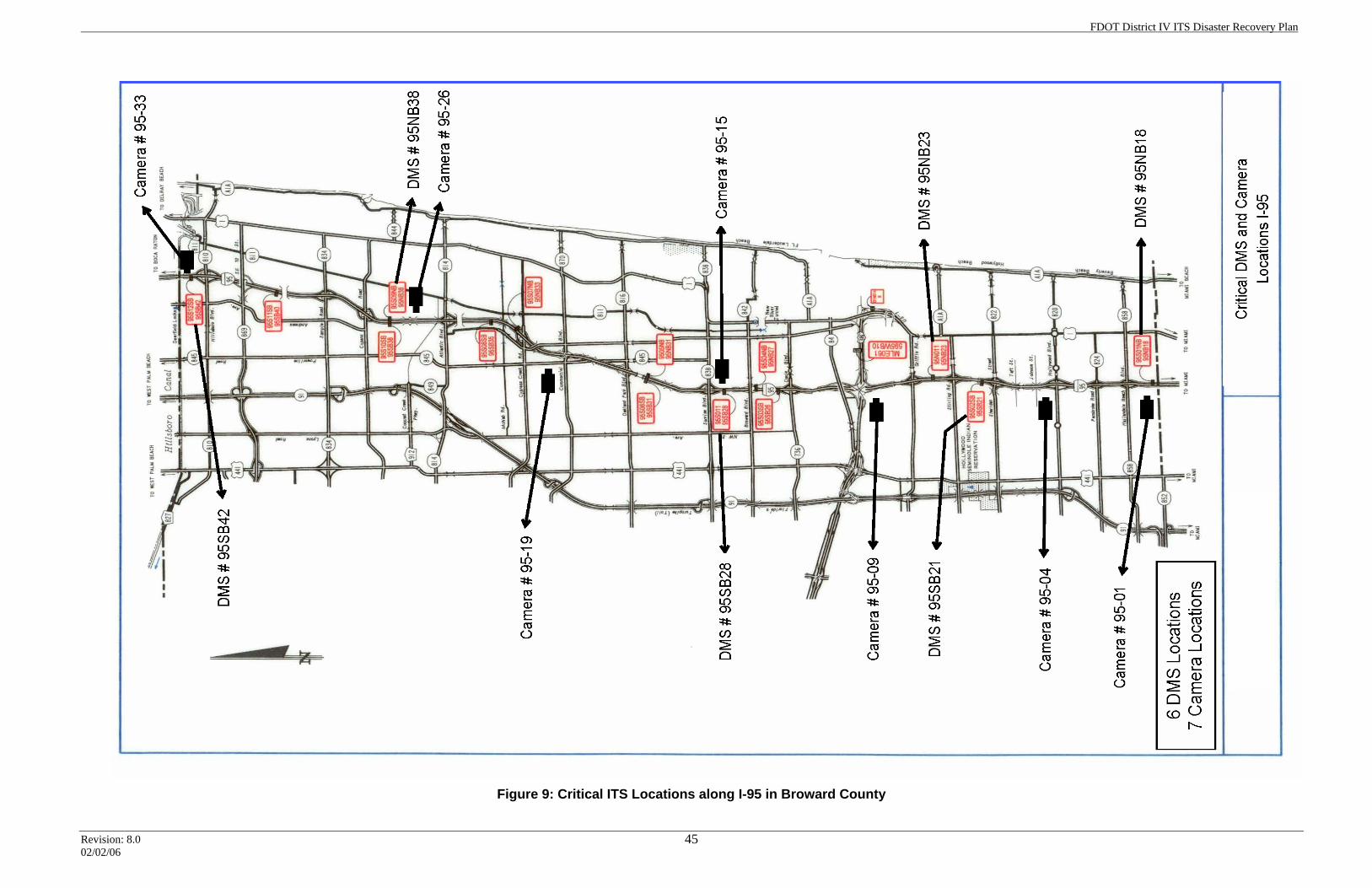
FDOT District IV ITS Disaster Recovery Plan
Revision: 8.0 02/02/06
45
Figure 9: Critical ITS Locations along I-95 in Broward County
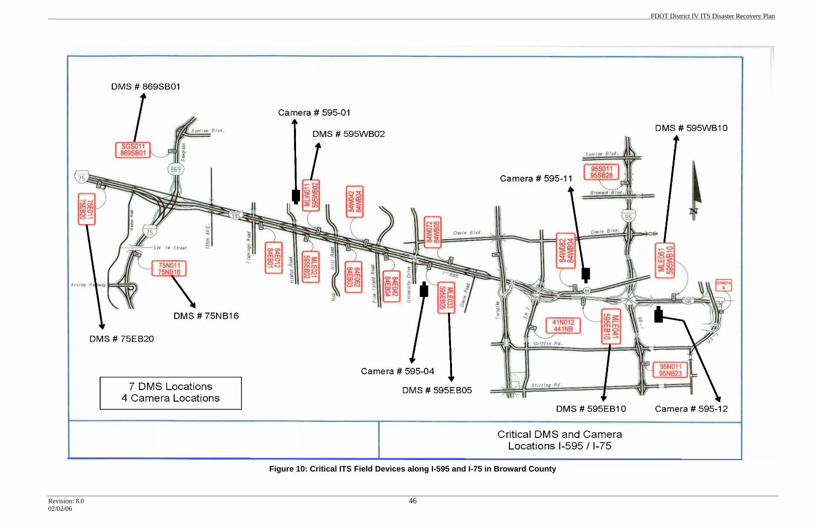
FDOT District IV ITS Disaster Recovery Plan
Revision: 8.0 02/02/06
46
Figure 10: Critical ITS Field Devices along I-595 and I-75 in Broward County
FDOT District IV ITS Disaster Recovery Plan
Revision: 8.0 02/02/06
47
6.4 Broward TMC Facility Procedures Within the Broward TMC hurricane plan, the following actions have been identified as part of the FDOT Broward TMC preparations:
6.4.1 Broward TMC Facility Preparation The Broward TMC is designed to withstand Category 2 hurricane conditions related to wind speed. The ATMS computer room portion of the Broward TMC facility is rated to withstand Category 5 conditions. The FDOT ITS operations staff will staff the FDOT Broward TMC for Category 1 and 2 storms. During Category 1 and 2 storms, the TMC staff will include the TMC Manager and the TMC IT Network Manager. For Category 3, 4, and 5 hurricanes, the FDOT ITS Operations Manager will notify the TMC Manager as to when the facility will be evacuated.
6.4.2 Coordination with Regional TMC The Southeast Florida Regional TMC Operations (SEFRTOC) committee has agreed to the meeting schedule shown below to coordinate efforts during these planned events. Each agency will contact its respective public information office and EOC for critical updates prior to each scheduled call. Road Ranger project managers (District IV, District VI, and Turnpike) will attend each teleconference. Smart Route Systems (511) will be invited to participate in all pre-storm and post-storm activities. Pre-storm Schedule
• Minus 96 hours – E-mail to schedule initial teleconference
• Minus 72 hours – Teleconference o Toll suspensions o EOC activation o Evacuation/contra-flow plans o Contact information
• Minus 48 hours – Teleconference o Status updates o Staffing levels o Road Ranger schedule/level o Traffic operations status (construction activities, signals)
• Minus 24 hours – Teleconference o Status updates o Agency policy – cessation of Road Ranger operations o Shelter information
FDOT District IV ITS Disaster Recovery Plan
Revision: 8.0 02/02/06
48
o Road closures o Diversion routes
• Minus 12 hours – Teleconference (if any area remains in a warning status) o Status updates
Post-storm Schedule
• Within 12 hours (or when Road Rangers are back in service) – Teleconference
o Operations level o ITS infrastructure o Storm damage o Road Ranger level o Curfew o Shelters o Schedule o Contact information
6.4.3 TMC Severe-Weather Supplies The FDOT Broward TMC has developed a severe-weather supplies list and procured the necessary supplies (a copy of the inventory list is attached to this document). The TMC Manager is responsible for inventorying the stored supplies prior to the start of hurricane season, and for re-supplying as indicated by the list. If any of the emergency supplies are utilized during any part of the hurricane season, the TMC Manager will conduct another inventory and reorder any necessary supplies.
6.4.4 Severe-Weather Radio The FDOT Broward TMC has been equipped with two severe-weather radios. The TMC Manager will begin to continuously monitor the severe-weather radio in the TMC 72 hours prior to the predicted hurricane landfall.
6.4.5 TMC Facility Generator The FDOT Broward TMC has been equipped with a building generator to supply electrical power during commercial power interruptions. As previously noted, the FDOT Broward TMC is a joint facility shared with BCTED, which is responsible for maintaining all facility infrastructure (including the generator). The Broward TMC IT Network Manager will be responsible for coordinating with the Broward County representatives (Joe King and Ed Gariboldi, at this writing) concerning the FDOT Broward TMC generator. Generally speaking, the FDOT Broward TMC generator and UPS operate in the following fashion:
FDOT District IV ITS Disaster Recovery Plan
Revision: 8.0 02/02/06
49
UPS runtime without A/C power or a generator is approximately three hours. It powers the first floor PCs, the video wall, the server room, lights, and many offices on the first floor. However, the UPS does not power any A/C equipment, including equipment in the server room. The generator is responsible for powering the following items and areas of the TMC building:
• Powers and recharges the UPS
• All lights for the building (first and second floor)
• First floor air handlers and A/C chillers for the building (second-floor air handlers are not powered)
• Server room A/C
• Most outlets on the first floor (those not covered by the UPS)
• Front elevator (back elevator is left unpowered) Generator runtime at full load is estimated at 24 hours, and the current running load to power the above systems is estimated at 40 percent. The generator fuel capacity is 2,200 gallons, an amount that is estimated to last 50 to 60 hours at 40 percent load. The fuel tank is not kept full; however, BCTED is responsible for monitoring storm situations and will fuel the generator when a storm is projected.
6.4.6 ITS Field Device Preparation When the identified critical ITS field devices have generator systems installed, it will be the ITS Maintenance Manager’s responsibility to fill to capacity each generator’s fuel tank at the bringing of the storm season. During the non-storm season, the tanks should be run down to nearly empty, while conducting periodic testing.
6.5 FDOT Broward TMC Facility Recovery This section describes events that will occur after the storm event has passed and once it is again safe to resume operational status. Immediately after the storm passes, the TMC staff will meet at the FDOT Broward TMC. This determination is made by the national hurricane center, which officially declares when the storm has passed. Any staff member who is unable to report should attempt to contact the TMC or supervisor and report his or her circumstances. After the TMC staff meets at the TMC, the FDOT ITS Operations Manager should check the TMC facility to ensure operations can be safely resumed. After the safety check, the TMC Manager will draw from those present to form operator teams that will restore normal operations. If the FDOT Broward TMC is deemed not capable of safe operations, the TMC staff will redeploy to the contingency site, in accordance with the disaster recovery plan. If any of the FDOT Broward TMC subsystems are not functional, the disaster recovery plan will be placed into effect.
FDOT District IV ITS Disaster Recovery Plan
Revision: 8.0 02/02/06
50
6.5.1 Emergency Communication Teams After the TMC staff meets at the TMC, a high-level meeting will take place to discuss the need to deploy the emergency communication system. If it is needed, the FDOT ITS Operations Manager will form two emergency communication teams responsible for deploying the emergency 470 MHz private radio-based communication system. One team will install the emergency radio system antenna at the Broward TMC and test the system. The other team will be dispatched to the FDOT materials yard near I-595 and I-75 to install the emergency radio system antenna and test the system. The emergency communication teams will report back to the TMC once their assigned systems are operational.
6.5.2 Damage Assessment Teams The FDOT ITS Operations Manager will form damage assessment teams to field-survey hurricane damage. The number of damage assessment teams will be determined at the time of the emergency. The damage assessment teams will utilize the CCTV camera system to survey the state roadway network and ITS field devices. Depending on the outcome of the CCTV survey, the damage assessment teams will conduct field reviews to assess the damage to ITS field device installations within the major state roadways of I-95, I-595, I-75 to the Miami-Dade county line, and the DMS locations along SR84 and SR7. Based on past hurricane damage experience, the local cellular phone network may not be in operation. The damage assessment teams will utilize the emergency radio system for communication with the TMC. The exception to this is the team deployed to I-75 from US27 to the Collier county line; they will utilize one of the satellite phones. The damage assessment teams will survey the ITS field device locations within their areas of responsibility for damage and electrical power. They will document the damage in the field and compile their findings into a report. The report will be delivered to the crisis assessment team for review. The repair of damaged ITS field devices will follow the disaster recovery process.
6.6 Broward TMC Hurricane Plan Flowchart The flowcharts presented in figures 11 and 12 were developed to facilitate hurricane preparations and recovery. A narrative for each flowchart is provided in the following sections.
6.6.1 Description of Figure 11 Listed below is a description of the information boxes in figure 11.
11.1 The TMC Manager will track hurricanes and tropical storms as they are announced by the National Weather Service.
11.2 As hurricanes or typical storms approach the South Florida area, the TMC Manager will generate an e-mail warning message, in accordance with the SEFRTOC.
FDOT District IV ITS Disaster Recovery Plan
Revision: 8.0 02/02/06
51
11.3 When the hurricane is within 72 hours from landfall, the FDOT ITS Operations Manager will initiate directives to perform facility and ITS system checks.
11.4 The IT Network Manager contacts BCTED concerning the fuel supply for the building generator.
11.5 The TMC Manager initiates a teleconference with regional TMC partners and Broward EOC.
11.6 The TMC Manager checks the severe-weather supplies. 11.7 The TMC Manager begins monitoring the severe-weather radio. 11.8 The FDOT ITS Maintenance Manager checks the fuel supplies for the
generators supporting critical ITS field devices. 11.9 The FDOT Freeway Operations Manager coordinates Road Ranger
activities with the TMC (for hurricane-specific operations). 11.10 The FDOT ITS Operations Manager discusses evacuation orders and
contra-flow plans. 11.11 The TMC Manager will deploy additional staff on duty to handle
evacuations orders (if needed). 11.12 When the hurricane is a maximum of 48 hours from landfall, the FDOT
ITS Operations Manager issues appropriate directives. 11.13 The FDOT Freeway Operations Manager continues to coordinate Road
Ranger activities (hurricane-specific operations) with the TMC. 11.14 The TMC Manager initiates a teleconference with the regional TMC
partners, in accordance with the SEFRTOC (to include calls to the EOC).
11.15 The FDOT ITS Operations Manager discusses updates with staff. 11.16 When the hurricane is within a maximum of 24 hours from landfall, the
FDOT ITS Operations Manager issues appropriate directives. 11.17 The FDOT District Secretary issues a formal notice of operations,
describing how the district will operate during the hurricane. 11.18 The FDOT ITS Program Manager conducts a staff meeting and assigns
responsibilities for responding to the hurricane.
6.6.2 Description of Figure 12 Listed below is a description of the information boxes in figure 12.
12.1 Duties of the FDOT ITS Operations Manager for Category 1 or 2
hurricanes.
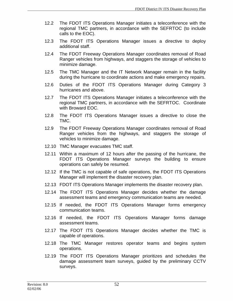
FDOT District IV ITS Disaster Recovery Plan
Revision: 8.0 02/02/06
52
12.2 The FDOT ITS Operations Manager initiates a teleconference with the regional TMC partners, in accordance with the SEFRTOC (to include calls to the EOC).
12.3 The FDOT ITS Operations Manager issues a directive to deploy additional staff.
12.4 The FDOT Freeway Operations Manager coordinates removal of Road Ranger vehicles from highways, and staggers the storage of vehicles to minimize damage.
12.5 The TMC Manager and the IT Network Manager remain in the facility during the hurricane to coordinate actions and make emergency repairs.
12.6 Duties of the FDOT ITS Operations Manager during Category 3 hurricanes and above.
12.7 The FDOT ITS Operations Manager initiates a teleconference with the regional TMC partners, in accordance with the SEFRTOC. Coordinate with Broward EOC.
12.8 The FDOT ITS Operations Manager issues a directive to close the TMC.
12.9 The FDOT Freeway Operations Manager coordinates removal of Road Ranger vehicles from the highways, and staggers the storage of vehicles to minimize damage.
12.10 TMC Manager evacuates TMC staff. 12.11 Within a maximum of 12 hours after the passing of the hurricane, the
FDOT ITS Operations Manager surveys the building to ensure operations can safely be resumed.
12.12 If the TMC is not capable of safe operations, the FDOT ITS Operations Manager will implement the disaster recovery plan.
12.13 FDOT ITS Operations Manager implements the disaster recovery plan. 12.14 The FDOT ITS Operations Manager decides whether the damage
assessment teams and emergency communication teams are needed. 12.15 If needed, the FDOT ITS Operations Manager forms emergency
communication teams. 12.16 If needed, the FDOT ITS Operations Manager forms damage
assessment teams. 12.17 The FDOT ITS Operations Manager decides whether the TMC is
capable of operations. 12.18 The TMC Manager restores operator teams and begins system
operations. 12.19 The FDOT ITS Operations Manager prioritizes and schedules the
damage assessment team surveys, guided by the preliminary CCTV surveys.
FDOT District IV ITS Disaster Recovery Plan
Revision: 8.0 02/02/06
53
12.20 The FDOT ITS Operations Manager coordinates the damage assessment teams’ field surveys.
12.21 FDOT ITS Maintenance Manager compiles a report that is to be shared with the crisis assessment team.
12.22 The crisis assessment team reviews the report and implements the disaster recovery plan as needed.
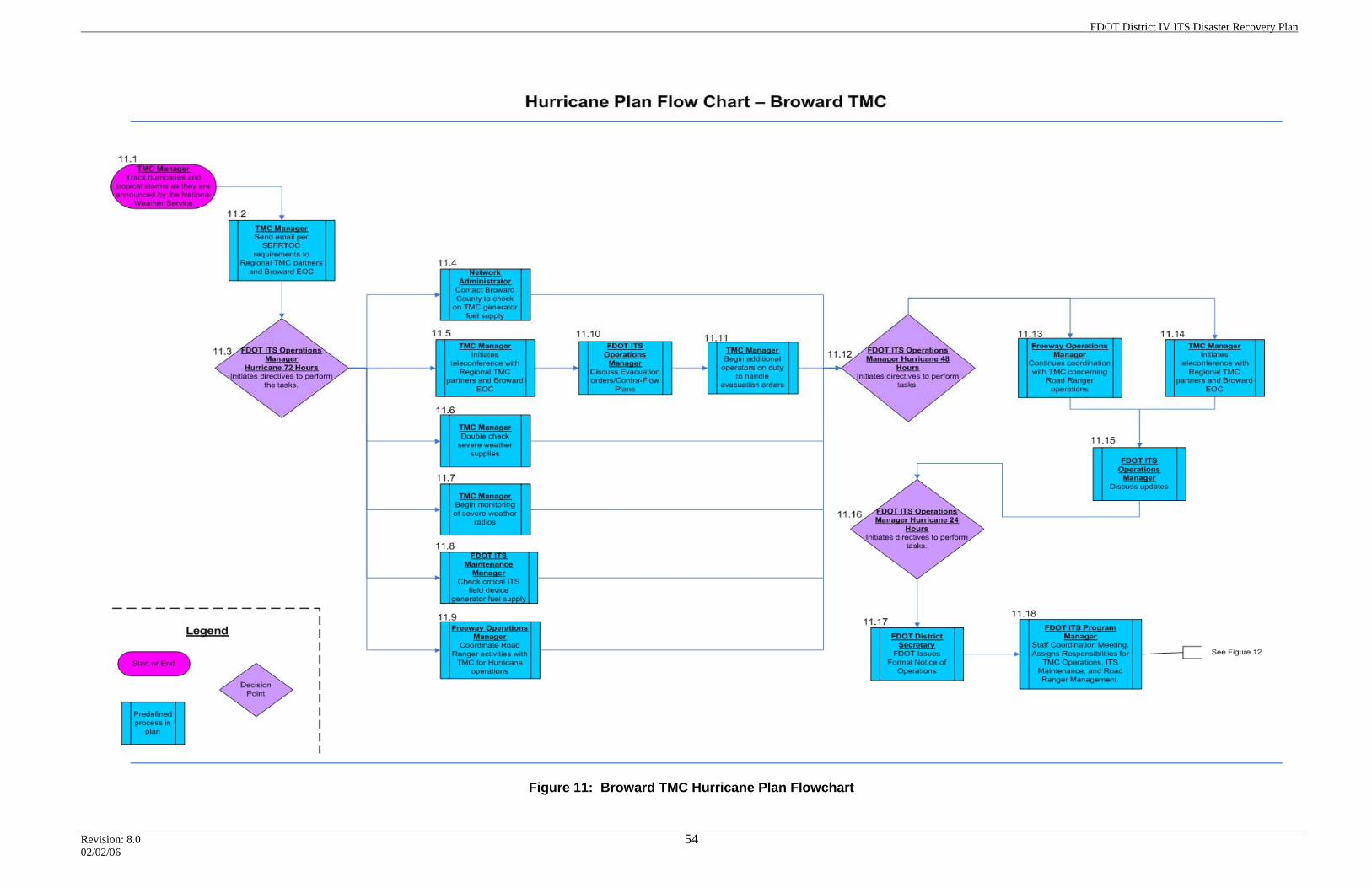
FDOT District IV ITS Disaster Recovery Plan
Revision: 8.0 02/02/06
54
Figure 11: Broward TMC Hurricane Plan Flowchart
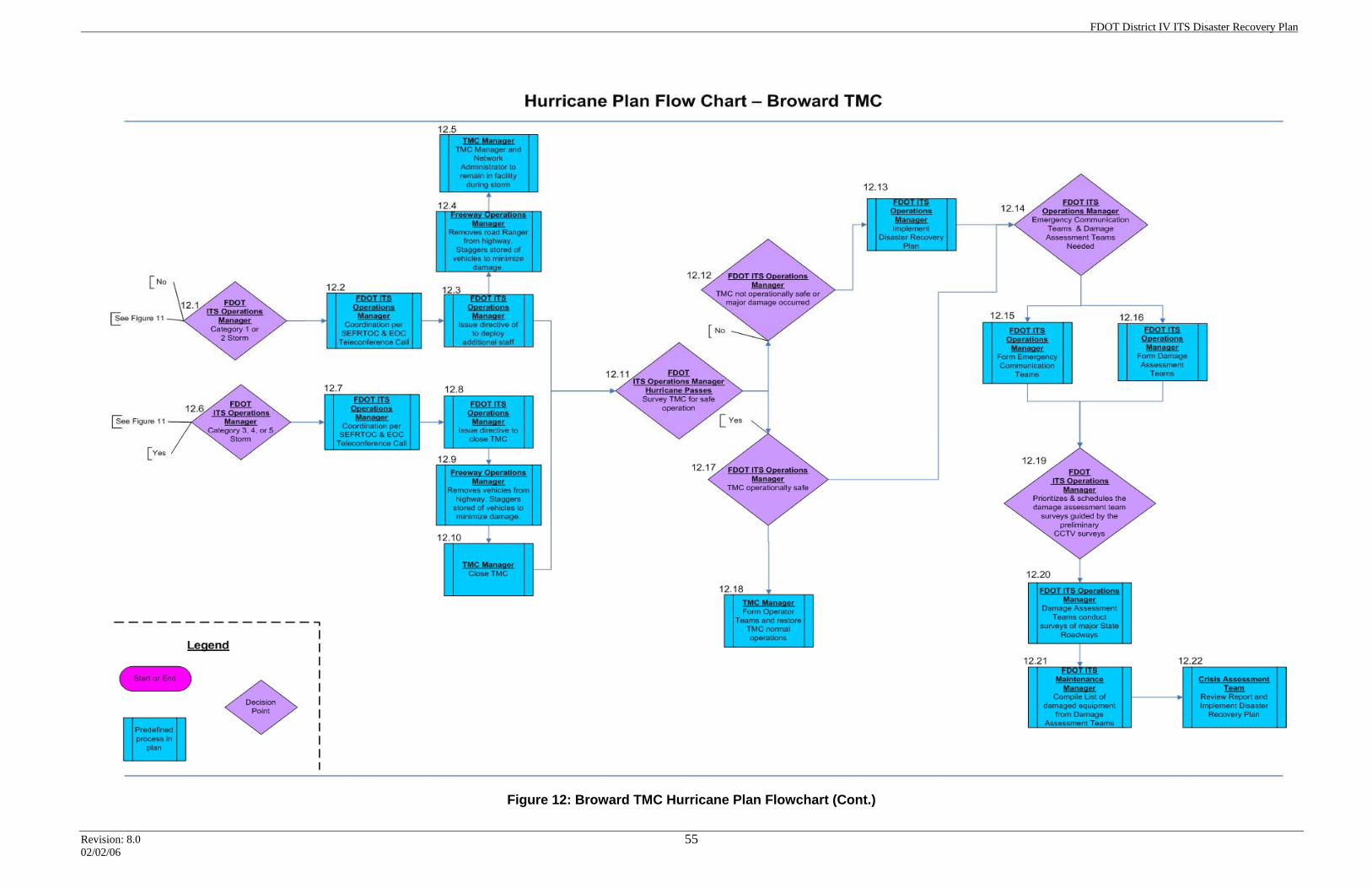
FDOT District IV ITS Disaster Recovery Plan
Revision: 8.0 02/02/06
55
Figure 12: Broward TMC Hurricane Plan Flowchart (Cont.)
FDOT District IV ITS Disaster Recovery Plan
Revision: 8.0 02/02/06
56
Section 7.0: Palm Beach ITMS Hurricane Preparedness Plan
7.1 Introduction FDOT’s “Hurricane Response Evaluation and Recommendations” document serves as the basis for a hurricane response action plan. This document identifies priority issues and assigns responsibilities for accomplishing a number of related objectives, as detailed below. The hurricane response action plan assigned the following ITS-related objectives at the district level:
• Develop a hurricane preparedness plan
• Acquire redundant communication means for the Road Rangers
• Place TMC staff at county emergency operations centers (EOCs)
• Develop emergency contracts
• Train in-house staff to troubleshoot and make repairs to ITS field devices
• Utilize the hourly counts from locations on major state corridors for monitoring increasing volumes and speed data on the State Highway System (SHS)
• Develop and maintain a spare parts inventory
• Obtain and maintain a minimum number of generators to power critical ITS field devices
• Ensure access to an inventory of portable traffic control devices (Highway Advisory Radio and DMS) prior to the emergency event
• Obtain backup communication means (such as satellite phones) for external TMC communications
Additional responsibilities were assigned concerning signal system operations; however, those objectives are not addressed within this document. FDOT’s District IV Emergency Operation Manual 2005 states that the Department has three basic emergency management responsibilities, as follows:
1. Address issues affecting employees and places of work in order to ensure continuity of Department business when work place emergencies occur;
2. Respond to local emergencies that, directly or indirectly, have an impact on or disrupt the multimodal transportation system; and
3. Respond when state emergencies are declared. This plan designates key Department individuals to accomplish these obligations.
This document does not attempt to change any of the requirements put forth by the cited manuals or documents; rather, it focuses on the steps and procedures that are needed from an ITS perspective as a hurricane approaches, strikes, and then moves past the area. This plan offers a structured response to major hurricanes. ITS Operations will determine what procedures or steps will be utilized for minor hurricanes and tropical storms.
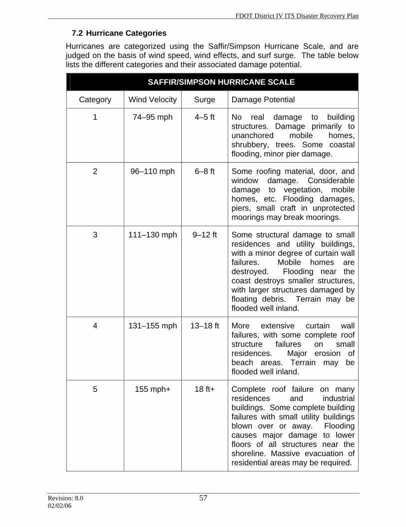
FDOT District IV ITS Disaster Recovery Plan
Revision: 8.0 02/02/06
57
7.2 Hurricane Categories Hurricanes are categorized using the Saffir/Simpson Hurricane Scale, and are judged on the basis of wind speed, wind effects, and surf surge. The table below lists the different categories and their associated damage potential.
SAFFIR/SIMPSON HURRICANE SCALE
Category Wind Velocity Surge Damage Potential
1 74–95 mph
4–5 ft No real damage to building structures. Damage primarily to unanchored mobile homes, shrubbery, trees. Some coastal flooding, minor pier damage.
2 96–110 mph 6–8 ft Some roofing material, door, and window damage. Considerable damage to vegetation, mobile homes, etc. Flooding damages, piers, small craft in unprotected moorings may break moorings.
3 111–130 mph 9–12 ft Some structural damage to small residences and utility buildings, with a minor degree of curtain wall failures. Mobile homes are destroyed. Flooding near the coast destroys smaller structures, with larger structures damaged by floating debris. Terrain may be flooded well inland.
4 131–155 mph 13–18 ft More extensive curtain wall failures, with some complete roof structure failures on small residences. Major erosion of beach areas. Terrain may be flooded well inland.
5 155 mph+ 18 ft+ Complete roof failure on many residences and industrial buildings. Some complete building failures with small utility buildings blown over or away. Flooding causes major damage to lower floors of all structures near the shoreline. Massive evacuation of residential areas may be required.
FDOT District IV ITS Disaster Recovery Plan
Revision: 8.0 02/02/06
58
7.3 Palm Beach ITMS Facility The hurricane response action plan identified several responsibilities related to TMC operations. Many of the responsibilities that were identified were previously addressed within the disaster recovery plan. The Palm Beach ITMS is located at 2200 Centrepark West Drive, Suite 200, in West Palm Beach, Palm Beach County, Florida. The building housing the facility is owned by Hedrick Brothers Construction. FDOT’s Project Manager, PB Farradyne, leases the facilities and equipment under contract with FDOT. PB Farradyne is responsible for electric and HVAC services. The one-story building was constructed using load-bearing masonry with filled cells and bond beams. The roofing membrane and tapered insulation is laid over metal decking attached to steel bar joists. A ‘‘Storefront’’ Dade County window system has been installed; it is rated to withstand the impact of a 2' × 4' object flying at 140 miles per hour.
7.3.1 Road Ranger Redundant Communication Means The hurricane response action plan identified the need for having redundant means for communicating with the Road Ranger vehicles when the cellular networks, such as Nextel and Verizon, are not available. Currently the FDOT is preparing a proposal for a UHF trunked radio system that will replace the Verizon cellular radios.
7.3.2 Develop Emergency Contracts PB Farradyne, in conjunction with FDOT, has previously arranged for emergency “H” contracts and supplemental amendments to the existing agreement to cover equipment damage, labor, and repair.
7.3.3 Backup Communication Means for External TMC Use The PB ITMS staff has proposed a backup satellite phone plan as an alternative that would allow for emergency communications to staff, other TMCs, and FDOT in the event of terrestrial telephone and radio failures. This proposal is currently under evaluation.
7.3.4 Place TMC Staff at County Emergency Operations Centers FDOT District IV Forest Hill maintenance personnel are assigned to the Palm Beach County Emergency Operations Center (EOC) to coordinate all FDOT functions and communicate with the PB ITMS via telephone and wireless phones.
7.3.5 Develop and Maintain a Spare Parts Inventory As part of the Palm Beach ITMS Field Device Maintenance and Relocation Requirements document (revised February 2004), the operations and maintenance contractor is required to stock specific parts and supplies for field device troubleshooting and repairs.
FDOT District IV ITS Disaster Recovery Plan
Revision: 8.0 02/02/06
59
7.3.6 Generator Power for Critical ITS Field Devices The PB ITMS maintenance contractor is required to maintain operations on all portable devices on the project. In case of a battery/solar power system failure, portable generators are required to recharge batteries and maintain operations. As experience has shown that these generators are vulnerable to theft, deployment of these portable devices should be limited to essential installations.
7.3.7 Portable Traffic Control Devices - DMS Spare portable DMS trailers are available for emergency deployment along the PB ITMS project and arterial routes. All portable DMS trailers have the capability to operate on a cellular phone GPRS protocol that allows for flexible placement—even outside the project area. All currently deployed devices are anchored with tie-down straps to prevent or minimize wind damage.
7.3.8 Monitor Volumes and Speed Data on the State Highway System Thirty locations along I-95 in Palm Beach County are monitored with PB ITMS SmartZones™ that contain RTMS speed radar devices. Average speed information is transmitted every 60 seconds via wireless radio back to the PB ITMS MIST™ operating system.
7.4 FDOT PB ITMS Facility Preparation As part of the hurricane preparedness plan, the following actions have been identified as essential parts of the FDOT TMC preparations.
7.4.1 Palm Beach ITMS Facility and ITS Field Device Preparation The PB ITMS facility is housed in a single-story, hurricane-rated (Category 4) structure in West Palm Beach. If any ITS Operations personnel decide to remain at the facility, it will be at their own risk.
7.4.2 TMC Severe-Weather Supplies PB ITMS has developed a severe-weather supplies list. These supplies have been procured. The inventory list is located in appendix E of this document. The TMC Operations Manager is responsible for inventorying the stored supplies prior to the start of hurricane season, and for restocking the inventory as indicated by the list. If any of the supplies are utilized during the hurricane season, the ITMS Operations Manager will conduct another inventory and order any necessary replacement supplies.
7.4.3 Severe-Weather Radio A NOAA weather radio tuned to specific regionally coded channels monitors broadcast radio reports around the clock. Prior to and during a weather emergency, the radio sounds an audible alarm and displays messages on conditions, watches, and warnings.
FDOT District IV ITS Disaster Recovery Plan
Revision: 8.0 02/02/06
60
7.4.4 TMC Facility Generator PB ITMS is equipped with a 60 KW diesel generator to supply electrical power during commercial power interruptions. The generator is connected to an auto-transfer switch that automatically detects any sustained outage and activates the generator. A one-hour UPS is also connected to the power system to maintain power and provide power surge protection. Backup generator power will be sufficient to operate all workstations, servers, the telephone system, the security system, and the HVAC units in the operations center and server room. The PB ITMS Project Manager and Engineer will be responsible for coordinating with Tektron Electrical Services and OK Generators for maintenance, troubleshooting, and fuel supplies.
7.4.5 ITS Field Device Preparation The ITS field devices installed on the ITMS project will be partially operational prior to a storm event. The PB ITMS Project Manager and engineers will establish the PB ITMS retraction plan, in coordination and with the approval of FDOT’s senior management. This plan will list each specific device and its disposition. Although the particulars will depend on individual locations, and whether the device is anchored, typical storm configurations will be as follows: (1) SmartZone tower lowered, solar panels retracted – device remains operational; (2) SmartZone put in transport state but left on pad; (3) SmartZone transported back to storage yard; (4) DMS trailer sign lowered; (5) DMS trailer transported back to storage yard.
7.5 ITMS Facility Operational Status during Storm Event As the facility is hurricane-rated and backup power is available, the staff will be advised and prepared to report and maintain operations during a storm event. This plan will be altered on a case-by-case basis depending on predicted winds, rain, and the field device retraction plan. The facility can be used as a staging area for other incident management team groups, including the Florida Highway Patrol and the Road Rangers.
7.5.1 ITS Field Device and Infrastructure during Storm Event Selected devices will remain operational during a storm. Only those devices that are not anchored or not able to establish wireless signals with MIST will be non-operational.
7.5.2 ITMS Facility Recovery Immediately upon passage of the storm, a damage assessment procedure will be initiated by the operations staff, the field engineer, and operations and maintenance staff. The storm will be considered to have left the area when the National Hurricane Center declares the storm has passed, or when the winds drop to 20 mph at both the ITMS facility and the residence of TMC staff. Relief operations staff will be contacted, and scheduling will be coordinated by the TMC Manager.
FDOT District IV ITS Disaster Recovery Plan
Revision: 8.0 02/02/06
61
If the ITMS facility is deemed not capable of safe operations, the TMC staff will redeploy to the contingency site, in accordance with the disaster recovery plan. If any of the ITMS subsystems are not functional, the disaster recovery plan will be placed into effect.
7.5.3 Emergency Communication Teams Several telecommunication options will be utilized to establish communications between the ITMS Project Manager, the Operations Manager, supervisors, and the Field Engineer. The following systems will be tested and utilized as appropriate (in order of priority): Verizon Cellular, Nextel Direct Connect, Nextel Cellular, BellSouth land lines, personnel cell phones on alternate carriers, and Nextel/internet text messaging.
7.5.4 Damage Assessment Teams The PB ITMS Project Manager, in coordination with the FDOT ITS Operations Manager (if possible), will coordinate dispatching of the PB Field Engineer and the operations and maintenance contractor for damage assessment. ITMS operations staff will utilize any operating CCTV cameras to provide road condition and damage reports. The damage assessment teams will survey all SmartZones, hub sites, arterial DMS trailers, and stored equipment (in that order of priority). The Project Manager and the Field Engineer will have the flexibility to prioritize the order of the surveys, depending on the track the storm followed. The damage assessment teams will communicate with the TMC to track and categorize any damage. After surveying the ITS field device locations within their area of responsibility to assess damage and verify the availability of electrical power, they will report any damage or loss of power to the TMC. The TMC will maintain a list of all reported damage.
7.5.5 ITS Field Device and Infrastructure Recovery Once the damage assessment teams have completed their surveys, the surveys will be compiled into a comprehensive ITS damage list. The FDOT ITS Maintenance Manager will review the ITS damage list with the FDOT Operations Manager, the FDOT ITS Program Manager, and the ITS maintenance contractor to determine a repair priority list based on operational needs, available spare parts, and time needed to effect repairs. If ITS subsystems are damaged to the point of being offline, the disaster recovery plan will be placed into effect.

FDOT District IV ITS Disaster Recovery Plan
Revision: 8.0 02/02/06
62
Appendix A: Broward TMC Contact List
FDOT District IV ITS Disaster Recovery Plan
Revision: 8.0 02/02/06
63
Appendix B: FDOT District IV Emergency Plans
FDOT District IV ITS Disaster Recovery Plan
Revision: 8.0 02/02/06
64
Appendix C: FDOT Broward TMC Severe-Weather Supplies
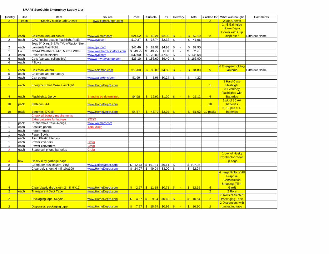
SMART SunGuide Emergency Supply List
Quantity Unit Item Source Price Subtotal Tax Delivery Total # asked for What was bought Comments2 each Stanley Mobile Job Chests www.HomeDepot.com 2 2 Job Chests
2 each Coleman 70quart cooler www.walmart.com $24.62 $ 49.24 $2.95 -$ $ 52.19 2
1 - 5 Gal. Igloo Home Depot
Cooler with Cup dispenser Different Name
2 each GPX Rechargeable Flashlight Radio www.qvc.com $19.37 $ 38.74 $2.32 -$ $ 41.06
2 eachJeep 5" Diag. B & W TV, w/Radio, Siren, Lantern& Flashlight www.qvc.com $41.46 $ 82.92 $4.98 -$ $ 87.90
1 Ea NOAA Weather Radio, Maxon WX80 www.weatherradiostore.com 49.95$ 49.95$ $3.00 -$ 52.95$ 4 each Polar fleece blanket www.qvc.com $32.00 $ 128.00 $7.68 -$ $ 135.68 6 each Cots (canvas, collapsible) www.armynavyshop.com $26.10 $ 156.60 $9.40 -$ $ 166.00 6 each Pillows
5 each Coleman lantern www.coleman.com $16.00 $ 80.00 $4.80 -$ $ 84.80 56 Energizer folding
lanterns Different Name5 each Coleman lantern battery2 each Can opener www.walgreens.com $1.99 $ 3.98 $0.24 -$ $ 4.22
1 each Energizer Hard Case Flashlight www.HomeDepot.com 11 Hard Case
Flashlight
4 each Flashlights, Dorcy Brand to be determined $4.98 $ 19.92 $1.20 -$ $ 21.12 4
3 Eveready Flashlights with
Batteries
10 pack Batteries, AA www.HomeDepot.com 101 pk of 36 AA
batteries
10 pack Batteries, D Cell www.HomeDepot.com $4.87 $ 48.70 $2.92 -$ $ 51.62 10 packs5 -12 pks of D
batteriesCheck all battery requirementsExtra batteries for laptops ?????
1 pack Rubbermaid Take-Alongs www.walmart.com1 each Satellite phone Tom Miller1 each Paper Plates1 each Paper Bowls1 each Asst. Plastic Utensils1 each Power inverters Craig1 each Power converters Craig# each Spare cell phone batteries Craig
# box Heavy duty garbage bags
1 box of Husky Contractor Clean
up bags8 Computer dust covers, vinyl www.OfficeDepot.com 12.73$ 101.84$ $6.11 -$ 107.95$ 2 Clear poly sheet, 6 mil, 10'x100' www.HomeDepot.com 24.97$ 49.94$ $3.00 -$ 52.94$
4 Clear plastic drop cloth, 2 mil, 9'x12' www.HomeDepot.com 2.97$ 11.88$ $0.71 -$ 12.59$ 4
4 Large Rolls of All-Purpose
Construction Sheeting (Film-
Gard)2 each Transparent Duct Tape www.HomeDepot.com 2 2 Rolls
2 Packaging tape, 54 yds www.HomeDepot.com 4.97$ 9.94$ $0.60 -$ 10.54$ 28 Rolls of Scotch Packaging Tape
2 Dispenser, packaging tape www.HomeDepot.com 7.97$ 15.94$ $0.96 -$ 16.90$ 22 Dispensers with
packaging tape
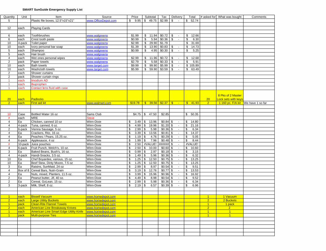
SMART SunGuide Emergency Supply List
Quantity Unit Item Source Price Subtotal Tax Delivery Total # asked for What was bought Comments5 Plastic file boxes, 12.5"x15"x21" www.OfficeDepot.com 9.95$ 49.75$ $2.99 -$ 52.74$
12 each Playing Cards
6 each Toothbrushes www.walgreens $1.99 $ 11.94 $0.72 -$ $ 12.66 6 each Crest tooth paste www.walgreens $0.99 $ 5.94 $0.36 -$ $ 6.30
10 4-pack Toilet paper www.walgreens $2.99 $ 29.90 $1.79 $ 31.69 10 each Ivory personal bar soap www.walgreens $1.39 $ 13.90 $0.83 -$ $ 14.73 5 each Shampoo www.walgreens $0.99 $ 4.95 $0.30 -$ $ 5.25 5 each Hair brush www.walgreens4 each Wet ones personal wipes www.walgreens $2.99 $ 11.96 $0.72 -$ $ 12.68 2 pack Paper towels www.walgreens $2.79 $ 5.58 $0.33 -$ $ 5.91
10 each Bath towels www.target.com $9.99 $ 99.90 $5.99 -$ $ 105.89 10 each Washcloth towels www.target.com $5.99 $ 59.90 $3.59 -$ $ 63.49 2 each Shower curtains2 pack Shower curtain rings1 each Imodium AD1 each Ibuprophen1 each Contact lens fluid with case
20 each Padlocks 208 Pks of 2 Master
Lock sets with keys2 each First aid kit www.walmart.com $19.78 $ 39.56 $2.37 -$ $ 41.93 2 1 160 pc. F/A kit We have 1 so far
10 Case Bottled Water 16 oz Sams Club $4.75 47.50$ $2.85 50.35$ # each MRE Steve4 Ea Chicken, canned 10 oz Winn-Dixie 3.49$ 13.96$ $0.84 -$ 14.80$ 4 4-pack Tuna, canned, 6 oz. Winn-Dixie 4.99$ 19.96$ $1.20 -$ 21.16$ 2 6-pack Vienna Sausage, 5 oz. Winn-Dixie 2.99$ 5.98$ $0.36 -$ 6.34$ 4 Ea Crackers, Ritz, 16 oz. Winn-Dixie 3.39$ 13.56$ $0.81 -$ 14.37$ 4 Ea Peaches / Pears, 15.25 oz. Winn-Dixie 1.19$ 4.76$ $0.29 -$ 5.05$ 4 6-pack Applesauce, 4 oz Winn-Dixie 1.99$ 7.96$ $0.48 -$ 8.44$ # 10-pack Juice pouches Winn-Dixie 2.50$ #VALUE! ###### -$ #VALUE!4 6-pack Fruit Punch, Welch's, 10 oz. Winn-Dixie 2.50$ 10.00$ $0.60 -$ 10.60$ 3 Ea Baked Beans, Bush's, 16 oz. Winn-Dixie 0.99$ 2.97$ $0.18 -$ 3.15$ 4 4-pack Handi-Snacks, 3.5 oz. Winn-Dixie 1.49$ 5.96$ $0.36 -$ 6.32$
10 Ea Chef Boyardee, various, 15 oz. Winn-Dixie 1.25$ 12.50$ $0.75 -$ 13.25$ 10 Ea Beef Stew, Dinty Moore, 7.5 oz Winn-Dixie 1.25$ 12.50$ $0.75 -$ 13.25$ 3 Ea Raisins, SunMaid, 24 oz Winn-Dixie 2.99$ 8.97$ $0.54 -$ 9.51$ 4 Box of 8 Cereal Bars, Nutri-Grain Winn-Dixie 3.19$ 12.76$ $0.77 -$ 13.53$ 4 Ea Nuts, mixed, Planters, 11.5 oz. Winn-Dixie 3.99$ 15.96$ $0.96 -$ 16.92$ 2 Ea Peanut butter, Jif, 40 oz. Winn-Dixie 4.49$ 8.98$ $0.54 -$ 9.52$ 2 Ea Cereal, GoLean, 15 oz. Winn-Dixie 2.99$ 5.98$ $0.36 -$ 6.34$ 3 3-pack Milk, Shelf, 8 oz. Winn-Dixie 2.19$ 6.57$ $0.39 -$ 6.96$
1 each Bissell Vacuum www.homedepot.com 1 1 Vacuum2 each Large Utility Buckets www.homedepot.com 2 2 Buckets1 pack Clean-Rite Flannel Towels www.homedepot.com 1 1 pack2 each American Line Breakaway Knives www.homedepot.com 2 2 1 each American Line Smart Edge Utility Kinfe www.homedepot.com 1 11 pack Multi-purpose Ties www.homedepot.com 1 1
FDOT District IV ITS Disaster Recovery Plan
Revision: 8.0 02/02/06
65
Appendix D: Palm Beach ITMS Contact List
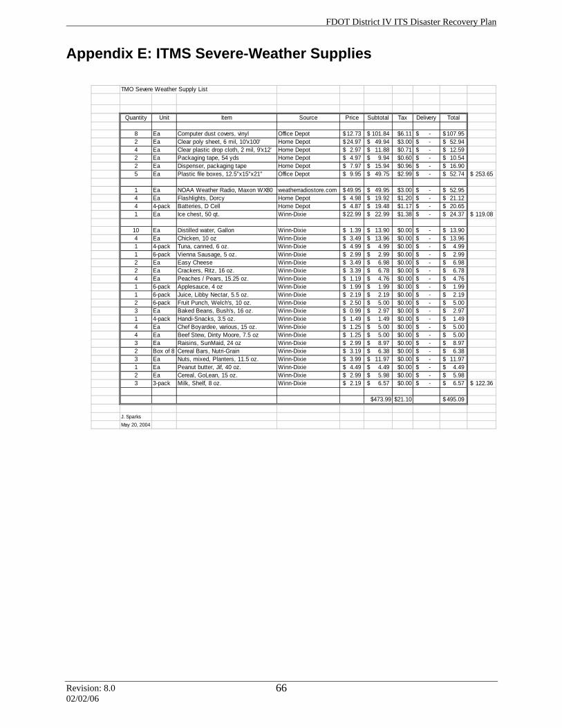
FDOT District IV ITS Disaster Recovery Plan
Revision: 8.0 02/02/06
66
Appendix E: ITMS Severe-Weather Supplies
TMO Severe Weather Supply List
Quantity Unit Item Source Price Subtotal Tax Delivery Total
8 Ea Computer dust covers, vinyl Office Depot 12.73$ 101.84$ $6.11 -$ 107.95$ 2 Ea Clear poly sheet, 6 mil, 10'x100' Home Depot 24.97$ 49.94$ $3.00 -$ 52.94$ 4 Ea Clear plastic drop cloth, 2 mil, 9'x12' Home Depot 2.97$ 11.88$ $0.71 -$ 12.59$ 2 Ea Packaging tape, 54 yds Home Depot 4.97$ 9.94$ $0.60 -$ 10.54$ 2 Ea Dispenser, packaging tape Home Depot 7.97$ 15.94$ $0.96 -$ 16.90$ 5 Ea Plastic file boxes, 12.5"x15"x21" Office Depot 9.95$ 49.75$ $2.99 -$ 52.74$ 253.65$
1 Ea NOAA Weather Radio, Maxon WX80 weatherradiostore.com 49.95$ 49.95$ $3.00 -$ 52.95$ 4 Ea Flashlights, Dorcy Home Depot 4.98$ 19.92$ $1.20 -$ 21.12$ 4 4-pack Batteries, D Cell Home Depot 4.87$ 19.48$ $1.17 -$ 20.65$ 1 Ea Ice chest, 50 qt. Winn-Dixie 22.99$ 22.99$ $1.38 -$ 24.37$ 119.08$
10 Ea Distilled water, Gallon Winn-Dixie 1.39$ 13.90$ $0.00 -$ 13.90$ 4 Ea Chicken, 10 oz Winn-Dixie 3.49$ 13.96$ $0.00 -$ 13.96$ 1 4-pack Tuna, canned, 6 oz. Winn-Dixie 4.99$ 4.99$ $0.00 -$ 4.99$ 1 6-pack Vienna Sausage, 5 oz. Winn-Dixie 2.99$ 2.99$ $0.00 -$ 2.99$ 2 Ea Easy Cheese Winn-Dixie 3.49$ 6.98$ $0.00 -$ 6.98$ 2 Ea Crackers, Ritz, 16 oz. Winn-Dixie 3.39$ 6.78$ $0.00 -$ 6.78$ 4 Ea Peaches / Pears, 15.25 oz. Winn-Dixie 1.19$ 4.76$ $0.00 -$ 4.76$ 1 6-pack Applesauce, 4 oz Winn-Dixie 1.99$ 1.99$ $0.00 -$ 1.99$ 1 6-pack Juice, Libby Nectar, 5.5 oz. Winn-Dixie 2.19$ 2.19$ $0.00 -$ 2.19$ 2 6-pack Fruit Punch, Welch's, 10 oz. Winn-Dixie 2.50$ 5.00$ $0.00 -$ 5.00$ 3 Ea Baked Beans, Bush's, 16 oz. Winn-Dixie 0.99$ 2.97$ $0.00 -$ 2.97$ 1 4-pack Handi-Snacks, 3.5 oz. Winn-Dixie 1.49$ 1.49$ $0.00 -$ 1.49$ 4 Ea Chef Boyardee, various, 15 oz. Winn-Dixie 1.25$ 5.00$ $0.00 -$ 5.00$ 4 Ea Beef Stew, Dinty Moore, 7.5 oz Winn-Dixie 1.25$ 5.00$ $0.00 -$ 5.00$ 3 Ea Raisins, SunMaid, 24 oz Winn-Dixie 2.99$ 8.97$ $0.00 -$ 8.97$ 2 Box of 8 Cereal Bars, Nutri-Grain Winn-Dixie 3.19$ 6.38$ $0.00 -$ 6.38$ 3 Ea Nuts, mixed, Planters, 11.5 oz. Winn-Dixie 3.99$ 11.97$ $0.00 -$ 11.97$ 1 Ea Peanut butter, Jif, 40 oz. Winn-Dixie 4.49$ 4.49$ $0.00 -$ 4.49$ 2 Ea Cereal, GoLean, 15 oz. Winn-Dixie 2.99$ 5.98$ $0.00 -$ 5.98$ 3 3-pack Milk, Shelf, 8 oz. Winn-Dixie 2.19$ 6.57$ $0.00 -$ 6.57$ 122.36$
$473.99 $21.10 495.09$
J. SparksMay 20, 2004
FDOT District IV ITS Disaster Recovery Plan
Revision: 8.0 02/02/06
67
Appendix F: ITMS Severe-Weather Plan
Palm Beach County Interim Traffic Management System
Severe-Weather Response Plan
(Revised December 15, 2005) Introduction The purpose of this plan is to outline the procedures for emergency preparedness, response, and recovery, primarily for coping with hurricanes and other weather emergencies. The plan may be applicable for use in other major emergencies as well. The first priority is the safeguarding of lives and property. The secondary objective is to keep the Interim Traffic Management System (ITMS) operational. The restoration/ redeployment of the system will begin as soon as practicable following the emergency. This document outlines the roles and responsibilities of the ITMS partners and the different responses before, during, and after a major weather event. For ITMS personnel, many of the instructions and contacts needed for response to severe weather are addressed in the ITMS Operations Manual.
FDOT District IV ITS Disaster Recovery Plan
Revision: 8.0 02/02/06
68
Section 1.0: Participant Roles
Evacuation of the population is the major issue in preparing for approaching hurricane. The ITMS is invaluable in providing information to evacuees. Consequently, any decision to shut down the field devices must be weighed against evacuees’ need for real-time travel information. These decisions will be made jointly with FDOT, the ITMS contractor, the field device maintenance contractor, and the Palm Beach County Emergency Operations Center. If and when the field devices are shut down, the ITMS still provides a valuable service as the focal point for information gathering and dissemination. The ITMS will continue to coordinate the activities of Road Rangers as long as they are operational.
1.1 Safeguarding Lives and Property ITMS services are especially valuable during the time when a hurricane is approaching. Consequently, the ITMS will remain open, and may even operate during unscheduled hours, during this period. Operators and the shift supervisor are expected to report to work during their assigned shifts regardless of weather conditions, and should plan accordingly. However, the complete evacuation of the ITMS may be necessary. Should evacuation be ordered, the senior staff member present is responsible for accounting for the ITMS staff. The senior staff member present will order the evacuation, account for the staff, and report the actions taken to the ITMS operations manager and the ITMS operations manager. In the event of an evacuation, some operations may continue to be performed remotely (e.g., Road Ranger coordination, information gathering and dissemination through the Road Rangers, FHP services, 511 service, Metro network services, and others). Remote operation of the ITMS will be orchestrated from the remote terminals at Palm Beach County Traffic Engineering, Boca Raton Traffic Engineering, or at the Broward TMC in Fort Lauderdale, subject to availability of the sites. This determination will be made jointly with FDOT, the ITMS contractor, and the operators of the potential remote locations. The ITMS building, while not “hardened,” is nonetheless substantial. The glazing is impact-resistant. The property owner will secure the exterior of the building.
1.2 System Operation The ITMS will be staffed with a scheduled minimum of two operators. Hurricane activities may require additional staff. During periods of severe weather conditions, the incidents requiring a response may increase to a level that is difficult to manage. In this case additional staff should be called in, and accurate records kept to the degree possible under the circumstances. The ITMS consists primarily of portable devices. In the event of extremely high winds, the SmartZones and portable DMS signs will be secured as described in the sections below. The ITMS will assist in the coordination of these activities. The field device maintenance contractor will keep the ITMS updated on the status of the devices. The financial responsibility for damages directly attributed to the storm is assumed by FDOT.
FDOT District IV ITS Disaster Recovery Plan
Revision: 8.0 02/02/06
69
The ITMS is set up to operate on a generator, and utilizes an uninterruptible power supply (UPS) as a backup and surge protector. This only provides for short-term operations; in the event of a prolonged power failure the ITMS will be closed, and remote operations will be established. The operating system will be shut down in an orderly manner as per the ITMS Operations Manual. As soon as power is again available at the ITMS, the system will be restarted. The ITMS will continue to disseminate weather and traffic information to 511, Metro Networks, and other agencies as long as such information is available and useful, and if it can be provided without jeopardizing the safety of the ITMS staff. This function may be performed from a remote location.
1.3 Agency Coordination
1.3.1 General Agency coordination will continue as described in the ITMS Operations Manual. Information specific to severe-weather conditions is listed in the following sections.
1.3.2 Road Ranger Service Patrol The ITMS will continue dispatch and coordination as long as the Road Rangers remain operational. FDOT and the Road Ranger contractor will jointly determine whether to reduce or suspend Road Ranger operations because of sustained high winds or other indications, and communicate the Road Ranger status with the ITMS.
1.3.3 Palm Beach County Emergency Operations Center (EOC) The Palm Beach County emergency management organization operates using a modified integrated incident command system/emergency support function (ICS/ESF)
organizational structure. FDOT’s role in the use and coordination of local resources is tied to 2 of the 17 ESFs: ESF #1, Transportation, and ESF #3, Public Works. The purpose of ESF #1 is to coordinate all emergency transportation resources for the response to and recovery from any disaster in Palm Beach County. ESF #1 is primarily involved in transporting vulnerable populations to safer locations, and transporting recovery-related resources into affected areas in Palm Beach County. By policy, all transportation service will be suspended when sustained winds reach
40 mph or greater, as reported by the National Weather Service. The purpose of ESF #3 is to define how the public infrastructure of Palm Beach County will be restored during and following a disaster in order to save lives and property. Policies of ESF #3 include the following: • Prioritizing affected areas based on impact assessment data • Coordinating emergency debris removal on essential transportation routes • Coordinating debris removal and disposal from public property • Prioritizing and implementing temporary emergency structural repairs at vital public
facilities, county roads, bridges, and drainage systems • Coordinating road closures
FDOT District IV ITS Disaster Recovery Plan
Revision: 8.0 02/02/06
70
• Establishing staging areas and logistical support bases for requested mutual aid resources (in coordination with all first-response agencies)
1.3.3.1 EOC Activation Levels Level 3 – Monitoring (normal) Level 2 – Partial activation Level 1 – Full activation
1.3.4 FDOT West Palm Beach Maintenance Upon activation of the EOC, FDOT sends two teams of two individuals to the EOC for the duration of the emergency. These teams work alternate 12-hour shifts. FDOT also has four-person, 24-hour staffing at the WPB maintenance facility. After landfall, FDOT
mobilizes six two-person teams for damage assessment and recovery. FDOT Maintenance’s pre-hurricane activities include the lockdown of all bascule bridges when wind speeds reach 40 mph. This determination is made in conjunction with the EOC and the Coast Guard. In addition, FDOT Maintenance will contact the ITMS for specific CCTV views both before and after the storm.
1.3.5 SunGuide 511 Traveler Information The 511 Center is to remain operational during severe weather.
Schedule The plan is broken down into a series of phases and the corresponding steps to be taken up to, during, and immediately following a hurricane or similar conditions. The schedule establishes a general guideline for protective actions before, during, and after a hurricane or similar event. The schedule may be modified to meet hazard constraints, response times, and other conditions that may occur during the weather event. Phase A includes an annual review. It also includes those steps to be performed and items to be maintained and checked (as a general preparedness activity) during normal times. Phase B is the pre-storm “alert” stage, when a storm is within 72 hours of possible landfall. The ITMS will initiate the alert at the direction of the FDOT project manager or the ITMS project manager. Phase C refers to those pre-storm activities performed during a “hurricane watch.” A hurricane watch is issued for a specified coastal area in which a hurricane or a hurricane-related hazard is a possible threat within 36 hours. Phase D refers to those pre-storm activities performed during a “hurricane warning.” A hurricane warning is issued when a hurricane with sustained winds of 74 miles per hour or higher is expected in a specified coastal area within 24 hours or less.
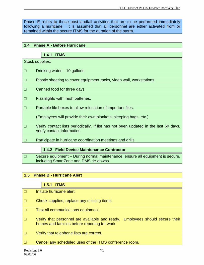
FDOT District IV ITS Disaster Recovery Plan
Revision: 8.0 02/02/06
71
Phase E refers to those post-landfall activities that are to be performed immediately following a hurricane. It is assumed that all personnel are either activated from or remained within the secure ITMS for the duration of the storm.
1.4 Phase A - Before Hurricane
1.4.1 ITMS Stock supplies: □ Drinking water – 10 gallons. □ Plastic sheeting to cover equipment racks, video wall, workstations. □ Canned food for three days. □ Flashlights with fresh batteries. □ Portable file boxes to allow relocation of important files.
(Employees will provide their own blankets, sleeping bags, etc.) □ Verify contact lists periodically. If list has not been updated in the last 60 days,
verify contact information □ Participate in hurricane coordination meetings and drills.
1.4.2 Field Device Maintenance Contractor □ Secure equipment – During normal maintenance, ensure all equipment is secure,
including SmartZone and DMS tie-downs.
1.5 Phase B - Hurricane Alert
1.5.1 ITMS □ Initiate hurricane alert. □ Check supplies; replace any missing items. □ Test all communications equipment. □ Verify that personnel are available and ready. Employees should secure their
homes and families before reporting for work. □ Verify that telephone lists are correct. □ Cancel any scheduled uses of the ITMS conference room.
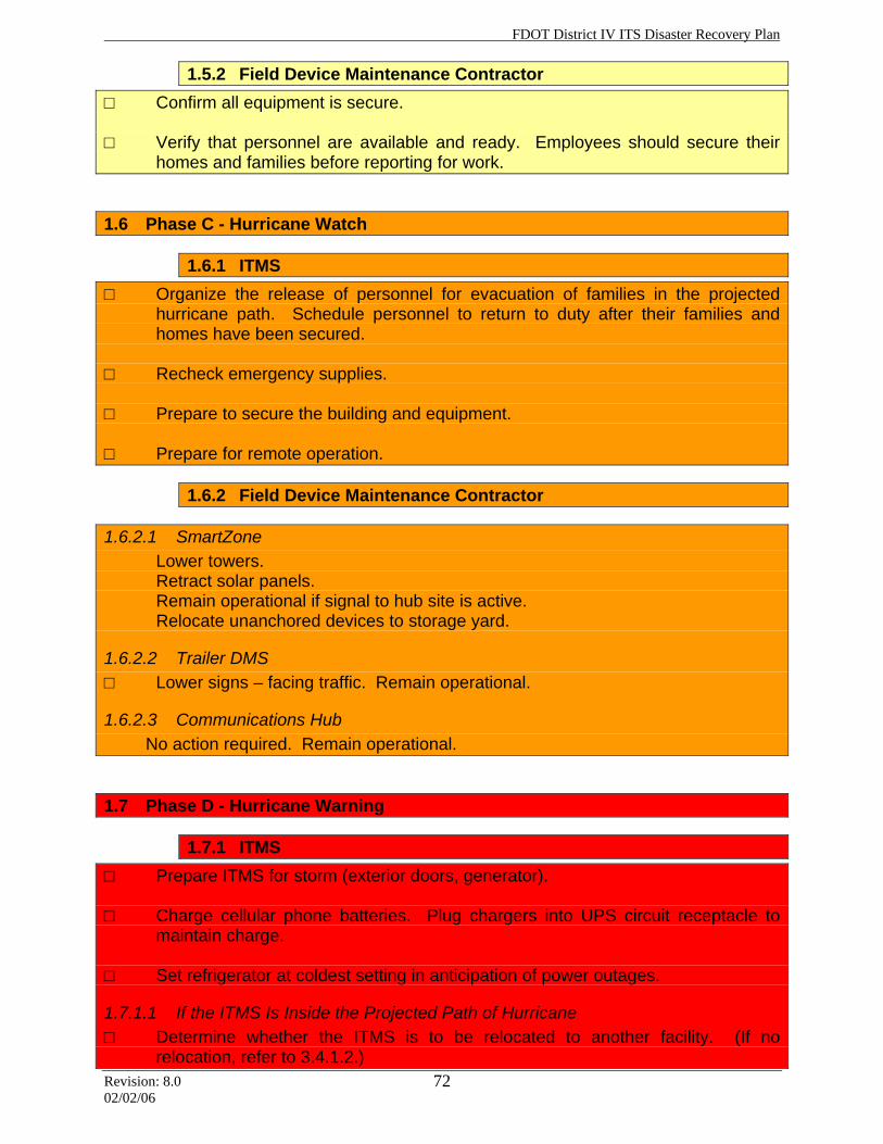
FDOT District IV ITS Disaster Recovery Plan
Revision: 8.0 02/02/06
72
1.5.2 Field Device Maintenance Contractor □ Confirm all equipment is secure. □ Verify that personnel are available and ready. Employees should secure their
homes and families before reporting for work.
1.6 Phase C - Hurricane Watch
1.6.1 ITMS □ Organize the release of personnel for evacuation of families in the projected
hurricane path. Schedule personnel to return to duty after their families and homes have been secured.
□ Recheck emergency supplies. □ Prepare to secure the building and equipment. □ Prepare for remote operation.
1.6.2 Field Device Maintenance Contractor
1.6.2.1 SmartZone Lower towers. Retract solar panels. Remain operational if signal to hub site is active. Relocate unanchored devices to storage yard.
1.6.2.2 Trailer DMS □ Lower signs – facing traffic. Remain operational.
1.6.2.3 Communications Hub No action required. Remain operational.
1.7 Phase D - Hurricane Warning
1.7.1 ITMS □ Prepare ITMS for storm (exterior doors, generator). □ Charge cellular phone batteries. Plug chargers into UPS circuit receptacle to
maintain charge. □ Set refrigerator at coldest setting in anticipation of power outages.
1.7.1.1 If the ITMS Is Inside the Projected Path of Hurricane □ Determine whether the ITMS is to be relocated to another facility. (If no
relocation, refer to 3.4.1.2.)
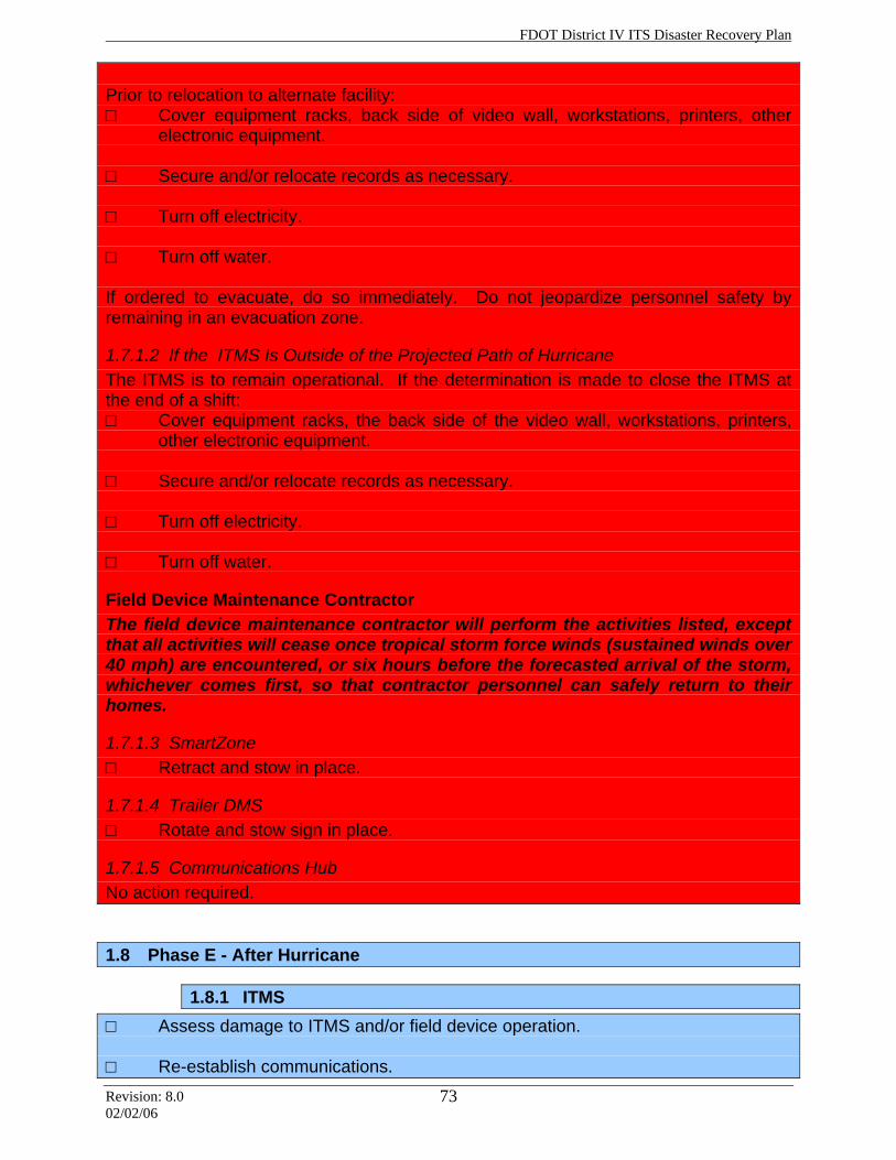
FDOT District IV ITS Disaster Recovery Plan
Revision: 8.0 02/02/06
73
Prior to relocation to alternate facility: □ Cover equipment racks, back side of video wall, workstations, printers, other
electronic equipment. □ Secure and/or relocate records as necessary. □ Turn off electricity. □ Turn off water. If ordered to evacuate, do so immediately. Do not jeopardize personnel safety by remaining in an evacuation zone.
1.7.1.2 If the ITMS Is Outside of the Projected Path of Hurricane The ITMS is to remain operational. If the determination is made to close the ITMS at the end of a shift: □ Cover equipment racks, the back side of the video wall, workstations, printers,
other electronic equipment. □ Secure and/or relocate records as necessary. □ Turn off electricity. □ Turn off water.
Field Device Maintenance Contractor The field device maintenance contractor will perform the activities listed, except that all activities will cease once tropical storm force winds (sustained winds over 40 mph) are encountered, or six hours before the forecasted arrival of the storm, whichever comes first, so that contractor personnel can safely return to their homes.
1.7.1.3 SmartZone □ Retract and stow in place.
1.7.1.4 Trailer DMS □ Rotate and stow sign in place.
1.7.1.5 Communications Hub No action required.
1.8 Phase E - After Hurricane
1.8.1 ITMS □ Assess damage to ITMS and/or field device operation. □ Re-establish communications.
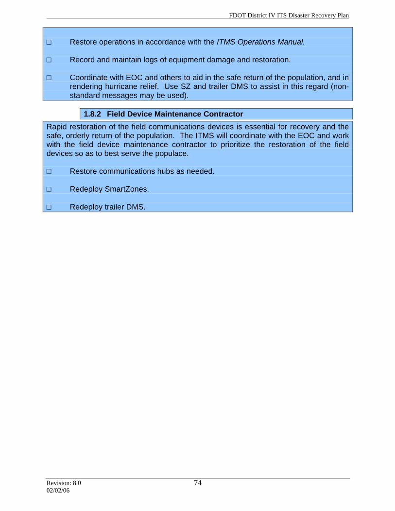
FDOT District IV ITS Disaster Recovery Plan
Revision: 8.0 02/02/06
74
□ Restore operations in accordance with the ITMS Operations Manual. □ Record and maintain logs of equipment damage and restoration. □ Coordinate with EOC and others to aid in the safe return of the population, and in
rendering hurricane relief. Use SZ and trailer DMS to assist in this regard (non-standard messages may be used).
1.8.2 Field Device Maintenance Contractor Rapid restoration of the field communications devices is essential for recovery and the safe, orderly return of the population. The ITMS will coordinate with the EOC and work with the field device maintenance contractor to prioritize the restoration of the field devices so as to best serve the populace. □ Restore communications hubs as needed. □ Redeploy SmartZones. □ Redeploy trailer DMS.