exterior masonry veneer supported by mpcwt
TRANSCRIPT

Exterior Brick Masonry VeneerSupported by Metal Plate Connected
Wood Trusses (MPCWT)
Overview
Revised 11/17/2016

SBCA has been the voice of the structural building
components industry since 1983, providing educational
programs and technical information, disseminating industry
news, and facilitating networking opportunities for
manufacturers of roof trusses, wall panels and floor trusses.
SBCA endeavors to expand component manufacturers’
market share and enhance the professionalism of the
component manufacturing industry.
Copyright © 2016 Structural Building Components Association.

Introduction
• Wood frame structures with attached brick masonry veneer cladding are a common form of residential construction throughout the United States, particularly in central and southeastern regions with moderate seismic and/or high wind activity

Introduction
• Brick veneer cladding is appreciated for its pleasant appearance, excellent thermal performance and its ability to prevent water penetration

Introduction
• “Simple rain screen” construction, shown at right is a common assembly.
• It consists of: – Brick masonry veneer at the
exterior side of the wall
– A wood frame wall at the interior
– Metal ties (veneer anchors) attaching the brick and wood
Photo: gobrick.com

Introduction
• The metal ties hold the brick veneer away from the wood framing creating an air space between the two
• This air space serves multiple role:– Drainage
– Thermal barrier
– Weather resistance
Photo: gobrick.com

Introduction
• Additionally, from a structural perspective the tie connection is important in transferring lateral loads between the brick veneer and wood framing
Photo: gobrick.com

Introduction
• Typically, the wood framing is designed to carry all lateral and gravity loads except for self-weight of the brick
• However, the brick does carry a portion of lateral load due to having higher stiffness than the wood framing
Photo: gobrick.com

Introduction
• No significant structural problems have been reported with brick veneer under typical scenarios: – The cladding is capable of
supporting its own weight all the way down to the foundation
– The cladding is supported by properly sized steel lintel angles and/or wood structural components over conventionally sized window and door openings

Introduction
• Supporting brick veneer cladding above larger openings such as a two-car garage door or large patio door can be more difficult
• The use of brick veneer supported by MPCWT is not covered by the prescriptive methods in the codes
• However, code compliance can be accomplished by both individual designs and by adhering to the recommendations that follow

Issue
• This presentation focuses on the gable end at the transition from a wider section of a building to a narrower section
• The concepts shown can be applied to many different situations utilizing MPCWT’s
Background
• Per IRC 2015, brick veneer masonry can be supported by wood framing when observing the stated limitations– Supporting brick veneer can
include steel angles bolted to wall framing or steel angles supported by beefed-up rafters
– A movement joint is required to be installed between veneers supported by foundation and veneers supported by wood or steel
• R703.8.2 Exterior veneer support
• R703.8.2.1 Support by steel angle
• R703.8.2.2 Support by roof construction

Background
• Additional, prescriptive installation requirements are specified in – The Masonry Society (TMS)
402/602
– The Brick Industry Association (BIA) Technical Notes 18A, 28, 31B, and 44B

Background
• The IRC provides two details for attaching a steel angle to wood framing, Figures R703.8.2.1 (right) and R703.8.2.2 (following slide)

Background
• In both details, there is an adjacent wood framed backup wall

Background
• However, the IRC 2015includes no prescriptive provisions to specifically address an exterior brick veneer wall supported directly by MPCWT
?

Background
• The detail below may be referred to by the building designer to achieve a code-conforming steel lintel connection
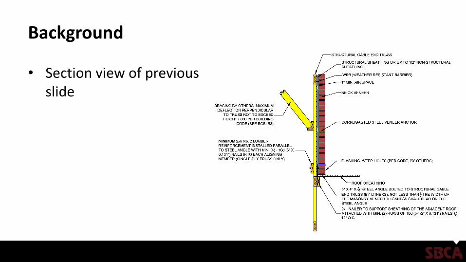
Background
• Section view of previous slide

Background
• The lateral support of brick veneer should be provided by the ties and wood backing system, including proper restraint of the MPCWT to resist the lateral loads imposed
• The ties must be capable of resisting tension and compression resulting from forces acting perpendicular to the truss plane
Photo: masonrymagazine.com

Background
• Direction for the design of MPCWTs carrying the brick veneer needs to be presented to the truss designer and/or the building designer
• Typical MPCWT design only accounts for loads in the plane of the truss.– Lateral loads (i.e., wind and
seismic) acting perpendicular to the face of the truss are not considered

Background
• Examples of supporting brick veneer with MPCWT utilizing a steel lintel are given in the following examples (a) and (b)

Background

Background
• For buildings with conventional construction that contain structural elements exceeding the limits in IRCSection R301 Design Criteria or otherwise not conforming to this code, the IRC has provisions regarding designing these elements in accordance with accepted engineering practice
• R301.1.3. Engineered design
Background
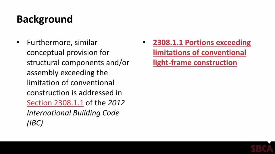
• Furthermore, similar conceptual provision for structural components and/or assembly exceeding the limitation of conventional construction is addressed in Section 2308.1.1 of the 2012 International Building Code (IBC)
• 2308.1.1 Portions exceeding limitations of conventional light-frame construction

Analysis
• For the individual truss carrying the brick/masonry wall through a steel lintel attached to the truss, the guidance and recommendations on the following slides are provided based on our professional judgment and the following sources:– 2015 IRC and 2015 IBC
– Wind loads specified in ASCE 7-10
– Fastener strengths specified in the NDS
– Masonry Structures standards contained in TMS 402/602.
– General guidance given in Brick Industry Association’s Technical Notes 18A, 28, 28B and 44B
Analysis
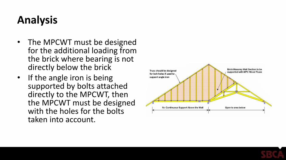
• The MPCWT must be designed for the additional loading from the brick where bearing is not directly below the brick
• If the angle iron is being supported by bolts attached directly to the MPCWT, then the MPCWT must be designed with the holes for the bolts taken into account.

Analysis
• Truss total load deflection is limited to L/600• Load Duration factor is CD=0.9• Creep factor for long-term deflection calculation shall be 1.5 for dry
lumber and 2.0 for unseasoned lumber– Creep is defined as time-dependent deformation of a structural member
under constant load. In this case brick dead load is a constant and/or sustained load (see ANSI/TPI 1-2002, 2007)
• Maximum weight of brick masonry veneer is 40 psf• Maximum height of brick masonry is 12’-8” per the IRC• Sheathing must be covered with a water-resistant membrane,
unless the sheathing is water resistant and the joints are sealed.

Analysis
• Steel lintel attachment to MPCWT should be per the following details:

Analysis

Analysis
• A minimum 6” x 4” x 5/16” (152 mm by 102 mm by 8 mm) steel angle, with the long leg placed vertically, shall be anchored to MPCWT using bolts per the following tables
• For assemblies with Structural Sheathing:
Bolt Spacing(Truss Vertical Member
Spacing)
Bolt Diameter 1,b
With Structural Sheathing (OSB, Plywood)
3/8-inch bolt diam. 1/2-inch bolt diam. 5/8-inch bolt diam. 3/4-inch bolt diam. 2
24 inches o.c.cMax. 4’-6”
brick heightMax. 6’-1”
brick heightMax. 7’-9”
brick heightMax. 9’-5”
brick height
16 inches o.c.cMax. 6’-11”brick height
Max. 9’-5”brick height
Max. 11’-10”brick height
Max. 14’-3” a
brick height
12 inches o.c.cMax. 9’-4”
brick heightMax. 12’-8”brick height
Max. 15’-11” a
brick heightMax. 19’-2” a
brick height
1 Bolt shear capacity is calculated based on 2015 NDS for Wood Construction for lumber with Specific Gravity G=0.42 (Spruce-Pine-Fir) with moisture content less than 19% and the following adjustment factors: CD=0.9, Ct and CM =1.0.2 Use only with minimum 2x4 vertical truss members. Fem=4700 psi, Fes=87000 psi, 5/16” Steel, no gap, Bolt Fyb=45000 psiBrick weight up to 40 PSF.a The maximum height of brick masonry veneer above the steel angle support using prescriptive requirements of 2015 IRC shall be 12’-8”. Weight of brick shall be included in truss design. b Pre-drill oval holes in the shelf angle for easier field installation adjustment.cIt must be noted that the design of the truss only accounts for the gravitational loads in the plane of the truss. The building designer needs to adequately account for loads normal to the face of the
truss and the bracing/restraint of the roof and wall system.

Analysis
• For assemblies with Non-Structural Sheathing:
Bolt Spacing(Truss Vertical Member
Spacing)
Bolt Diameter1,b
With up to ½” of Non-Structural Sheathing (Weather Resistant Barrier, Insulation, etc.)
3/8-inch bolt diam. 1/2-inch bolt diam. 5/8-inch bolt diam. 3/4-inch bolt diam. 2
24 inches o.c.cMax. 3’-1”
brick heightMax. 4’-4”
brick heightMax. 5’-6”
brick heightMax. 6’-8”
brick height
16 inches o.c.cMax. 4’-9”
brick heightMax. 6’-8”
brick heightMax. 8’-5”
brick heightMax. 10’-3”brick height
12 inches o.c.cMax. 6’-6”
brick heightMax. 9’-0”
brick heightMax. 11’-5”brick height
Max. 13’-9” a
brick height
1 Bolt shear capacity is calculated based on 2015 NDS for Wood Construction for lumber with Specific Gravity G=0.42 (Spruce-Pine-Fir) with moisture content less than 19% and the following adjustment factors: CD=0.9, Ct and CM =1.0.2 Use only with minimum 2x4 vertical truss members. Fem=4700 psi, Fes=87000 psi, 5/16” Steel with ½” gap between steel and truss, Bolt Fyb=45000 psi, Brick weight up to 40 PSF.a The maximum height of brick masonry veneer above the steel angle support using prescriptive requirements of 2015 IRC shall be 12’-8”. Weight of brick shall be included in truss design.b Pre-drill oval holes in the shelf angle for easier field installation adjustment.cIt must be noted that the design of the truss only accounts for the gravitational loads in the plane of the truss. The building designer needs to adequately account for loads normal to the face of the
truss and the bracing/restraint of the roof and wall system.

Analysis
• An alternative connection using (3) 2x6’s to support the brick masonry veneer directly above the 2x6’s

Analysis
• Screw spacing and maximum brick height details for the (3) 2x6 masonry support system are found in the following table:
Fasten Master TLOK08/LOG008 or Simpson SDS25800 or USP WS8 Screws 1
8” minimum screw length
SP/DFL SG=0.50 HF/SPF SG=0.42
2 Staggered Rows of Screws @ 8” o.c.b,c Max. 15’-3” a
brick heightMax. 12’-11” a
brick height
2 Staggered Rows of Screws @ 12” o.c.b,c Max. 10’-1”brick height
Max. 8’-6”brick height
2 Staggered Rows of Screws @ 16” o.c.b,c Max. 7’-6”brick height
Max. 6’-4” brick height
2 Staggered Rows of Screws @ 24” o.c.b,c Max. 4’-11”brick height
Max. 4’-1”brick height
1 Screw shear capacity is calculated based on 2015 NDS for Wood Construction for lumber with Specific Gravity G=0.42 (Spruce-Pine-Fir) and Specific Gravity G=0.50 (Douglas Fir-Larch) with moisture content less than 19% and the following adjustment factors: CD=0.9, Ct and CM =1.0. 3” main member, 4-1/2” side memberUse only with minimum 2x6 members. a The maximum height of brick masonry veneer above the steel angle support using prescriptive requirements of 2015 IRC shall be 12’-8”. b Screws to be staggered half the oc spacing with a minimum 1-3/4” edge distance and 6” end distance. Weight of brick shall be included in truss design.cIt must be noted that the design of the truss only accounts for the gravitational loads in the plane of the truss. The building designer needs to adequately account
for loads normal to the face of the truss and the bracing/restraint of the roof and wall system.

Analysis
• Another alternative connection using (3) 2x6’s to support the brick masonry veneer:

Analysis
• An alternative connection using 2-ply MPCWT directly below to support the brick masonry veneer:

Analysis
• An alternative connection using 2x_ material between MPCWT to support the brick masonry veneer:

Analysis
• The maximum slope of the roof construction without stops welded to the steel angle shall be 7:12
• Supporting the brick veneer with trusses with slopes from 7:12 up to 12:12 shall have stops, with a minimum size of 3”x3”x ¼” (76 mm x76 mm x 6 mm) steel plates, welded to the angle at a maximum spacing of 24” (610 mm) o.c. along the angle or as approved by the building official.
7
12
≤12
12

Analysis
• Lateral support is provided by the ties and backing system.
• The ties must be capable of resisting tension and compression resulting from forces acting perpendicular to truss plane.
• Stainless steel ties specified under ASTM A 240 or A 580
• Corrosion protected ties such as zinc coated corrugated steel ties, minimum 22 U.S. gauge thick (0.0299”), 7/8” x 6” (0.76mm x 22 mm x 152 mm) complying with ASTM A 653 and A 153 class B2

Analysis
• Veneer ties shall be spaced at maximum 32” o.c. (610 mm) horizontally and 24” o.c. vertically and shall support max 2.67 ft2 (0.25 m2) of brick veneer wall area
• For new construction, wall stud spacing of 16” o.c. is recommended so that ties can be anchored at this spacing

Analysis
• Strand wire ties are less susceptible to corrosion than corrugated steel sheet ties
• Minimum strand wire size diameter shall be 9 U.S. gauge [(0.148”) or (4 mm)] and be spaced same as corrugated steel ties and shall have a hook embedded in the mortar joint
Analysis
• The following tables provide recommendations for maximum vertical tie spacing for high wind areas when structural gable truss vertical members are spaced at 24”, 16” and 12” on center spacing
• In the areas that are susceptible to both high wind and seismic loads, masonry brick veneer system should be evaluated by an RDP to ensure that brick veneer cladding can resist both seismic and wind design loads

Analysis
• Maximum vertical tie spacing for assemblies with structural sheathing
Wind Speed(3-sec Peak Gust)
Wind1,2,9
Pressure (psf)
Maximum Vertical spacing for Ties in inches1,2,3,4,8 8d (0.131” x 2.5”) Ring-Shank Nails
With ½” Structural Sheathing (OSB, or Plywood) and 2” of Nail penetration4
Truss members @ 24” o.c. Truss members @ 16” o.c. Truss members @ 12” o.c.
SPF SYP SPF SYP SPF SYP
115 mph 19.1 165 165 245 245 245 245
120 mph 20.8 165 165 245 245 245 245
130 mph 24.4 16 165 245 245 245 245
140 mph 28.3 14 165 21 245 245 245
150 mph 32.5 12 126 18 186 245 245
160 mph 37.0 10 126 16 186 21 245
180 mph 46.8 NA7 NA7 12 186, 7 17 187
1 The vertical tie spacing is based on wind loads derived from ASCE 7-10 Components and Cladding – Method 1 (simplified – Figure 30.5-1, Zone 5, Effective wind area = 10 sf), located in Exposure category B, h = 30 ft., importance factor (I=1) and no topographic influence (Kzt=1.0). For other heights, exposure, importance factor and topographic influence, an engineered design is recommended. Table based on a tie in every vertical.
2 Net Design Wind Pressures from ASCE 7-10 Figure 30.5-1 have been multiplied by 0.6 for Allowable Stress Design.3 Nail withdrawal strength is for truss lumber with Specific Gravity G=0.42 (Spruce-Pine-Fir (SPF)) and G=0.55 (Southern Yellow Pine (SYP)) with moisture content less
than 19% and the following adjustment factors: CD=1.0, Ct=0.8, CM, Ceg, and Ctn=1.0. See FEMA Technical Fact Sheet No. 5.4 Attachment of Brick Veneer in High-Wind Regions.
W = 1800G2D x 1.6 SPF NV = 66.55 SYP NV = 114.124 Nail embedment depth of 2” was assumed for 8d common ring-shank nails (0.131”-diameter x 2 ½ ”-long) (1-1/2” truss plus ½” structural sheathing). A minimum of
3 (0.131” x 2”) nails required attaching the sheathing to the truss for every tie.5 The maximum vertical spacing allowed by the Brick Industry Association’s Technical Notes 28 is 24” & requires an anchor for every 2.67 sq. ft. of wall area.6 Where the wind pressure exceeds 30 psf, reduce wall area supported by each anchor to max. 2 SF per the IRC R703.8.4.1 & the Brick Industry Association’s Technical
Note 287 Where wind pressure exceeds 40 psf do not space anchors more than 18” vertically & horizontally per the Brick Industry Association’s Technical Note 288 Additional anchors required around openings larger than 16” in either dimension. See the IRC or IBC for these requirements.9It must be noted that the design of the truss only accounts for the gravitational loads in the plane of the truss. The building designer needs to adequately account for
loads normal to the face of the truss and the bracing/restraint of the roof and wall system.

Analysis
• Maximum vertical tie spacing for assemblies with non-structural sheathing
Wind Speed(3-sec Peak Gust)
Wind1,2,9
Pressure (psf)
Maximum Vertical spacing for Ties in inches1,2,3,4,8 8d (0.131” x 2.5”) Ring-Shank Nails
With Non-Structural Sheathing (Weather Resistant Barrier, Insulation, etc.) and 1-1/2” of Nail penetration in truss member.
Truss members @ 24” o.c. Truss members @ 16” o.c. Truss members @ 12” o.c.
SPF SYP SPF SYP SPF SYP
115 mph 19.1 15 165 23 245 245 245
120 mph 20.8 14 165 21 245 245 245
130 mph 24.4 12 165 18 245 245 245
140 mph 28.3 10 165 15 245 21 245
150 mph 32.5 9 126 13 186 18 245
160 mph 37.0 8 126 12 186 16 245
180 mph 46.8 NA7 NA7 9 16 12 187
1 The vertical tie spacing is based on wind loads derived from ASCE 7-10 Components and Cladding – Method 1 (simplified – Figure 30.5-1, Zone 5, Effective wind area = 10 sf), located in Exposure category B, h = 30 ft., importance factor (I=1) and no topographic influence (Kzt=1.0). For other heights, exposure, importance factor and topographic influence, an engineered design is recommended. Table based on a tie in every vertical.
2 Net Design Wind Pressures from ASCE 7-10 Figure 30.5-1 have been multiplied by 0.6 for Allowable Stress Design.3 Nail withdrawal strength is for truss lumber with Specific Gravity G=0.42 (Spruce-Pine-Fir (SPF)) and G=0.55 (Southern Yellow Pine (SYP)) with moisture content less
than 19% and the following adjustment factors: CD=1.0, Ct=0.8, CM, Ceg, and Ctn=1.0. See FEMA Technical Fact Sheet No. 5.4 Attachment of Brick Veneer in High-Wind Regions.
W = 1800G2D x 1.6 SPF NV = 49.9 SYP NV = 85.64 Nail embedment depth of 1-1/2” was assumed for 8d common ring-shank nails (0.131”-diameter x 2 ½ ”-long).5 The maximum vertical spacing allowed by the Brick Industry Association’s Technical Notes 28 is 24” & requires an anchor for every 2.67 sq. ft. of wall area.6 Where the wind pressure exceeds 30 psf, reduce wall area supported by each anchor to max. 2 SF per the IRC R703.8.4.1 & the Brick Industry Association’s Technical
Note 287 Where wind pressure exceeds 40 psf do not space anchors more than 18” vertically & horizontally per the Brick Industry Association’s Technical Note 288 Additional anchors required around openings larger than 16” in either dimension. See the IRC or IBC for these requirements.9It must be noted that the design of the truss only accounts for the gravitational loads in the plane of the truss. The building designer needs to adequately account for
loads normal to the face of the truss and the bracing/restraint of the roof and wall system.

Analysis
• Flashing and weep holes shall be located in the brick veneer wythe above the steel angle per the building codes.
• Flashing should consist of normal base flashing, step flashing and counter flashing installed directly on the adjacent (i.e., lower) roof sheathing.
• Weep holes shall be at a maximum spacing of 33” (838 mm) o.c. and shall be not less than 3/16” (5 mm) in diameter.

Analysis
• Create vertical expansion joints @ a maximum 25’ (7.6 m) o.c.

Analysis
• The actual location of vertical expansion joints in a structure depends on the structural configuration as well as the expected amount of horizontal movement
• Expansion joints are typically sized similar to a mortar joint, usually between 3/8” (10 mm) and ½” (13 mm)

Analysis
• Vertical expansion joints should also be considered with: – Corners– Offsets – Setbacks– Wall intersections– Changes in the wall height– Wall backing system changes – Brick veneer support changes– Wall function or climatic
exposure changes

Analysis
• MPCWT may also be used to support brick veneer at dormer locations.
• Depending on where the dormer is placed, the truss may need to be designed with an additional point load from a header carrying the front of the dormer brick veneer loading.

Conditions of Use
• Metal plate connected wood trusses can effectively support brick masonry veneer when properly designed to do so.
• Code compliant use of MPCWT to support brick veneer may be accomplished by both individual designs and by adhering to the recommendations shown here.
• The concepts shown can be applied to many different situations utilizing MPCWT’s and are presented only as a guide for use by a qualified Building Designer and/or Contractor.

References
• American Forest & Paper Association (AF&PA). 2015 National Design Specification® (NDS®) for Wood Construction. AF&PA, 1111 19th Street, NW, Suite 800, Washington, DC 20036. http://www.awc.org/
• American Concrete Institute, Masonry Standard Joint Committee (MSJC), Building Code requirements for Masonry Structures (ACI 530-11/ASCE 5-11/TMS 402-11) and Specifications for Masonry Structures (ACI 530.1-11/ASCE 6-11/TMS 602-11). http://www.asce.org/Product.aspx?ID=2147487569&ProductID=197024187
• IRC. International Residential Code (2015 edition). International Code Council, Inc., Washington, DC. http://publicecodes.cyberregs.com/icod/irc/2015/index.htm
• IBC. International Building Code (2015 edition). International Code Council, Inc., Washington, DC. http://publicecodes.cyberregs.com/icod/ibc/2015/index.htm
• ASCE, 2010. Minimum Design Loads for Buildings and Other Structures (ASCE 7-10), American Society of Civil Engineers, Reston, VA. http://www.asce.org/Product.aspx?id=25769807967&productid=154164477
• Masonry Advisory Council. Supporting Exterior Brick Veneer on Wood Construction http://www.maconline.org/tech/construction/bwood/bwood4/bwood4.html
• The Brick Industry Association. Technical Notes on Brick Construction 18A, 28, 28A and 44B. http://www.gobrick.com/Technical-Notes