flashing installation masonry veneer
DESCRIPTION
Installation Manual for FlashingTRANSCRIPT

7/18/2019 Flashing Installation Masonry Veneer
http://slidepdf.com/reader/full/flashing-installation-masonry-veneer 1/6
Flashing Installation: Masonry Veneer
MASONRY CONSTRUCTION GUIDE
Scope
This brief presents general informationon the installation of flashing. It’sintent is to provide instructional infor-mation on how to successfully installflashing for typical conditions encoun-tered in masonry veneer on frameconstruction. This guide does not pre-clude flashing details presented on thearchitectural documents. This guideaddresses the installation of flexibleflashing membranes since this type of membrane is most commonly utilizedin masonry veneer on frame construction.
Introduction
Many water penetration problems in
veneer walls can be traced back to flash-
ing inadequacies. Flashing installation for
masonry veneer construction is very simi-
lar to flashing installation for cavity walls,
and is just as important. The critical lo-
cations are the same: inner and outer
corners, horizontal laps, and flashing end
terminations. However, there are some
differences that must be addressed to
ensure the flashing functions as intended.
Flashing Installation atBase of Wall
Water penetration in masonry veneeconstruction can occur at the base of thewall. Ideally, flashing should be installedcontinuously along the base of the wallThis would eliminate the need to lap theflashing. However, this is rarely possibleso laps must be made. Flashing should
be lapped a minimum of 6 inches. If theflashing is not self-adhering, the lap musbe sealed with a mastic or adhesivecompatible with the flashing material
Figure 1
FLASHING INSTALLATION AT FOUNDATION
RESOURCE INFORMATION FROM THE INTERNATIONAL M ASONRY INSTITUT
TECHNOLOGY BRIEF April 2004
Section 2.7.3
TM

7/18/2019 Flashing Installation Masonry Veneer
http://slidepdf.com/reader/full/flashing-installation-masonry-veneer 2/6
Manufacturers of flashing materialsshould recommend an appropriate ad-hesive. If the flashing is dry-lapped with-out an adhesive, water that collects onthe flashing can flow between the lapand into the building. The flashing needs to run vertically upthe backup so that the building wrap canoverlap it a minimum of 6 inches. If the
vertical leg of the flashing is left exposed,water could easily flow behind the flash-ing. Extend the horizontal leg of theflashing flush with or beyond the face of the masonry unless specified otherwise.Flashing that is terminated within the wallcan result in water flowing underneaththe flashing into the building, or into thecore holes of the masonry unit.
Flashing Above Openings
Flashing should be installed above allopenings. Flashing that is installed abovea window or door usually terminates at both ends to prevent water that has col-lected on the flashing from flowing intothe cores of the unit or into the windowor door jamb. One way to terminatethe flashing is to extend it beyond theopening and turn up the ends to form apan or end dam (see Figure 2). Extending the flashing beyond theopening in increments of 4 inches as-
sures that the flashing can be neatly in-serted into a head joint. Trim the flash-ing in the head joint short of the exteriorface so that it is not visually unaccept-able, but do not cut it so short that wa-ter penetrates the unit or wall (seeFigure 2). The vertical end of the flash-ing should be lapped under the building wrap a minimum of 6 inches. An alternative to turning up the hori- zontal end of the flashing is to install pre-fabricated end dams beyond the open-ing. If a prefabricated end dam is not
self-adhering, it must be fully set in masticthat is compatible with the flashing ma-terial. The vertical end of the prefabri-cated end dam must be inserted beneaththe building wrap. This can be accom-plished by creating a small cut in thebuilding wrap and inserting the verticalleg of the end dam beneath it (seeFigure 3). End dams are commonlyrequired below window openings andcan be installed in a similar manner.
Figure 3
PREFABRICATED FLASHING END DAM
Figure 2
FIELD FORMED FLASHING END DAM

7/18/2019 Flashing Installation Masonry Veneer
http://slidepdf.com/reader/full/flashing-installation-masonry-veneer 3/6
is tedious and requires additional timeand care by the mason. Flashing outercorners is a two-step process (see Figure4). First, the flashing must be extended6 or 8 inches beyond the interior cornerof the backup. Then the flashing mem-brane should be cut along the horizon-tal plane. This will form a flap that
can be rotated 90o flush to the sheathing(see Figure 4a). If the flashing is not selfadhering, the flap must be set in masticthat is compatible with the flashingmaterial. The second step is similar to the firstThe flashing should be extended beyondthe interior corner backup, cut, and
Figure 4FIELD FORMED FLASHING OUTER CORNER
Flashing Installation atOuter Corners
Flashing continuity must be maintainedaround corners because they are moresusceptible to water penetration thanother areas of the wall. Flashing installation at outer corners
7/18/2019 Flashing Installation Masonry Veneer
http://slidepdf.com/reader/full/flashing-installation-masonry-veneer 4/6
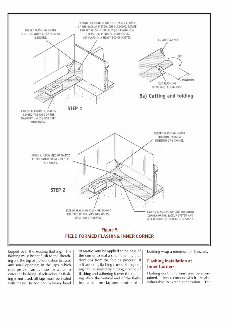
Figure 5FIELD FORMED FLASHING INNER CORNER
apped over the existing flashing. Thelashing must be set flush to the sheath-ng and the top of the foundation to avoidany small openings in the laps, whichmay provide an avenue for water toenter the building. If self-adhering flash-ng is not used, all laps must be sealedwith mastic. In addition, a heavy bead
of mastic must be applied at the base of the corner to seal a small opening that develops from the folding process. If self-adhering flashing is used, the open-ing can be sealed by cutting a piece of flashing and adhering it over the open-ing. Also, the vertical end of the flash-ing must be lapped under the
building wrap a minimum of 6 inches.
Flashing Installation atInner Corners
Flashing continuity must also be main-tained at inner corners which are alsovulnerable to water penetration. The

7/18/2019 Flashing Installation Masonry Veneer
http://slidepdf.com/reader/full/flashing-installation-masonry-veneer 5/6
proper flashing installation at inner cor-ners is similar to flashing outer cornersand can be just as time consuming. Flashing installation at inner cornersis a two-step process (see Figure 5). Theflashing should be extended 6 to 8 inchesbeyond the inner corner of the backupand cut at the corner intersection. Thecut will form a flap that can be rotated
90o over the flashing membrane and set flush against the sheathing (see Figure5a). If the flashing membrane is not self-adhering, the flaps must be thoroughlysealed with mastic that is compatiblewith the flashing material. The second step is similar to the first.The flashing membrane should be ex-tended beyond the interior corner of thebackup, cut, and lapped in the samemanner as step one. A heavy bead of mastic must be applied at the corner
base to seal a small opening which de-velops from the folding process. If self-adhering flashing is used, no additionalsealing is required. The vertical leg of the flashing must be lapped under thebuilding wrap a minimum of 6 inches.
Flashing Installation of Prefabricated Corners
The cutting and folding process requiredto maintain flashing continuity at innerand outer corners can be eliminated by
installing a prefabricated flashing corner.Prefabricated corners will totally encap-sulate the corner, ensuring flashing con-tinuity. If self-adhering flashing is not utilized, the prefabricated corner must be thoroughly set in mastic that’s com-patible with the flashing material. Pre-fabricated corners provide quick, easyinstallation and assure a continuous flash-ing membrane around corner locations(see Figures 6 and 7). The vertical legsof the prefabricated flashing corners must be lapped under the building wrap a
minimum of 6 inches.
Conclusion
The details shown in this guide are so-lutions to common situations that occurin masonry veneer construction. Theintent is to show solutions but not pre-clude other options put forth by thecontractor or architect. Often, field con-ditions demand adjustments to detailsshown on project drawings.
Figure 6
PREFABRICATED FLASHING OUTER CORNER
Figure 7
PREFABRICATED FLASHING INNER CORNER

7/18/2019 Flashing Installation Masonry Veneer
http://slidepdf.com/reader/full/flashing-installation-masonry-veneer 6/6
InternationalMasonryInstitute
42 East Street Annapolis, MD 21401
1-800-IMI-0988www.imiweb.org
This document is intended for the use of industry professionals who are competent to evaluate the significance andlimitations of the information provided herein. This publication should not be used as the sole guide for masonry design andconstruction, and IMI disclaims any and all legal responsibility for the consequences of applying the information.
© IMI 2004. All Rights Reserved