experimental modal analysis of an automotive powertrain
DESCRIPTION
VibrationsTRANSCRIPT
Experimental Modal Analysis of an Automotive Powertrain
C. Delprete1,a, A. Galeazzi1,b and F. Pregno1,c 1Politecnico di Torino, C.so Duca degli Abruzzi, 24 – 10129 Torino
[email protected], [email protected], [email protected]
Keywords: Experimental, modal analysis, powertrain, engine, vibration.
Abstract The work is devoted to study the dynamic properties of a powertrain, performing an experimental modal analysis (EMA). The aim is to determinate structural modes and frequency response function (FRF) using an experimental approach. Two types of excitation mechanism are applied and compared for the EMA: a modal exciter (electromagnetic shaker system) and an impact hammer. Both the analyses with modal shaker and with impact hammer are carried on measuring the acceleration of the structure in the same set of eighty-one points. In both cases, the excitation is performed along three directions (vertical, lateral and longitudinal with respect to the structure). The two different modal analysis methodologies are described, and results (modal parameters such as natural frequencies, damping ratios and modal shapes are identified with commercial software) are compared. The comparison is made in term of result accuracy, reliability and testing time required.
Introduction
The noise, vibration, and harshness (NVH) performances are one of the major challenges in the automotive design field. In a vehicle, there are many sources of noise and vibration: engine, driveline, brakes, tire contact patch and road surface. Designers have to consider NVH during the development of a new internal combustion engine. Noise and vibration reduction is fundamental for the comfort of the passengers. Another design milestone is the weight reduction in order to decrease fuel consumption and pollutant emissions. Weight reduction has not to compromise the structural performance since a lighter structure could not match NVH characteristic requested for passengers’ comfort. Experimental modal analysis (EMA) can help designers to study NVH characteristic of an existing engine in order to set a series of goals to improve a new design project. Moreover, NVH performances of new engines can be evaluated. EMA is based on vibration measurements in order to obtain frequency response function relating output vibration to input excitation.
The EMA is performed on a three cylinder spark ignition engine with gearbox in order to evaluate natural frequencies, damping ratios and mode shapes. It is a multi-input multi-output analysis (MIMO): output responses are accelerations and they are measured with piezoelectric transducers (accelerometers), input signals are obtained using two different excitation instruments. The final critical analysis of the experimental results allows understanding which excitation technique is more suitable.
Instrumentation
The test-bench is set up by: • 1 Impact Hammer PCB PiezotronicsI�C. model T086C03; • 1 Modal Exciter Dongling Vibration model ESD-045 with PA-1200 power amplifier; • 3 accelerometers PCB PiezotronicsI�C. model TLB356A12; • 1 load cell PCB PiezotronicsI�C. model 208C03; • 1 portable front-end LMS SCADAS III model 305; • 1 Hydraulic Floor Crane; • Suspension equipment; • 1 personal computer; • LMS Test.lab software.
Applied Mechanics and Materials Vols. 24-25 (2010) pp 71-76Online available since 2010/Jun/30 at www.scientific.net© (2010) Trans Tech Publications, Switzerlanddoi:10.4028/www.scientific.net/AMM.24-25.71
All rights reserved. No part of contents of this paper may be reproduced or transmitted in any form or by any means without the written permission of TTP,www.ttp.net. (ID: 198.208.209.27-30/08/12,19:03:07)
Experimental methodology
Eighty-one points of measure were identified in order to obtain a complete model of the powertrain, which gives a good representation of the geometry of the whole structure and its components (as illustrated in [3, 4]). The tridimensional model is created with LMS TestLab software using the Cartesian coordinates of these points. The experimental modal analysis was performed using two different excitation instruments: impact hammer and modal exciter (electromagnetic shaker). The powertrain was suspended by means of two springs in both cases, in order to reproduce free-free conditions. The analysis of the experimental data allows the comparison of the two different excitation methods. Modal exciter As regards to the use of modal exciter, the excitation was applied into two points of connection
between the instrument and the structure. In this way it was possible to excite the structure along its three main directions: longitudinal (x in Fig 3), transversal (y in Fig 3) and vertical (z in Fig 3).
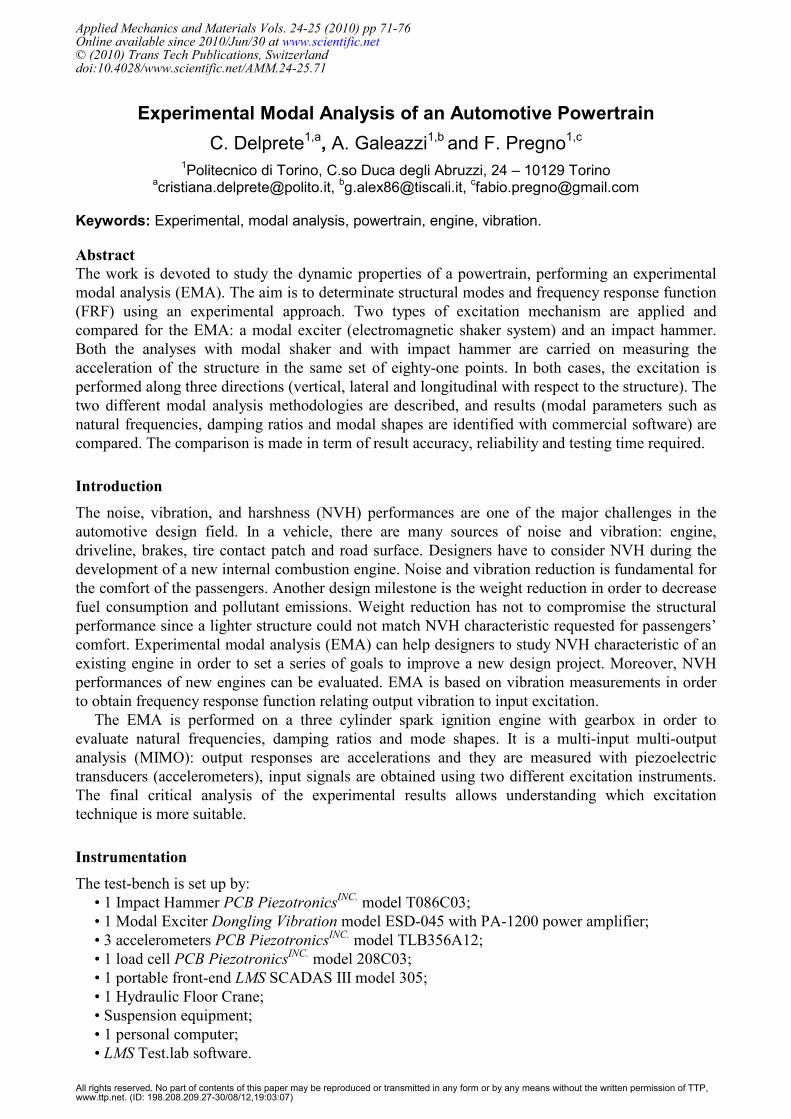
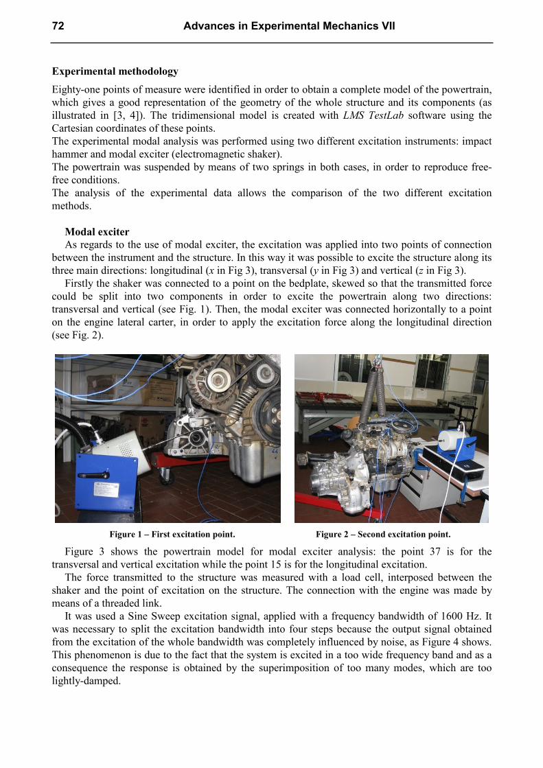
Firstly the shaker was connected to a point on the bedplate, skewed so that the transmitted force could be split into two components in order to excite the powertrain along two directions: transversal and vertical (see Fig. 1). Then, the modal exciter was connected horizontally to a point on the engine lateral carter, in order to apply the excitation force along the longitudinal direction (see Fig. 2).
Figure 1 – First excitation point. Figure 2 – Second excitation point.
Figure 3 shows the powertrain model for modal exciter analysis: the point 37 is for the transversal and vertical excitation while the point 15 is for the longitudinal excitation.
The force transmitted to the structure was measured with a load cell, interposed between the shaker and the point of excitation on the structure. The connection with the engine was made by means of a threaded link.
It was used a Sine Sweep excitation signal, applied with a frequency bandwidth of 1600 Hz. It was necessary to split the excitation bandwidth into four steps because the output signal obtained from the excitation of the whole bandwidth was completely influenced by noise, as Figure 4 shows. This phenomenon is due to the fact that the system is excited in a too wide frequency band and as a consequence the response is obtained by the superimposition of too many modes, which are too lightly-damped.
72 Advances in Experimental Mechanics VII
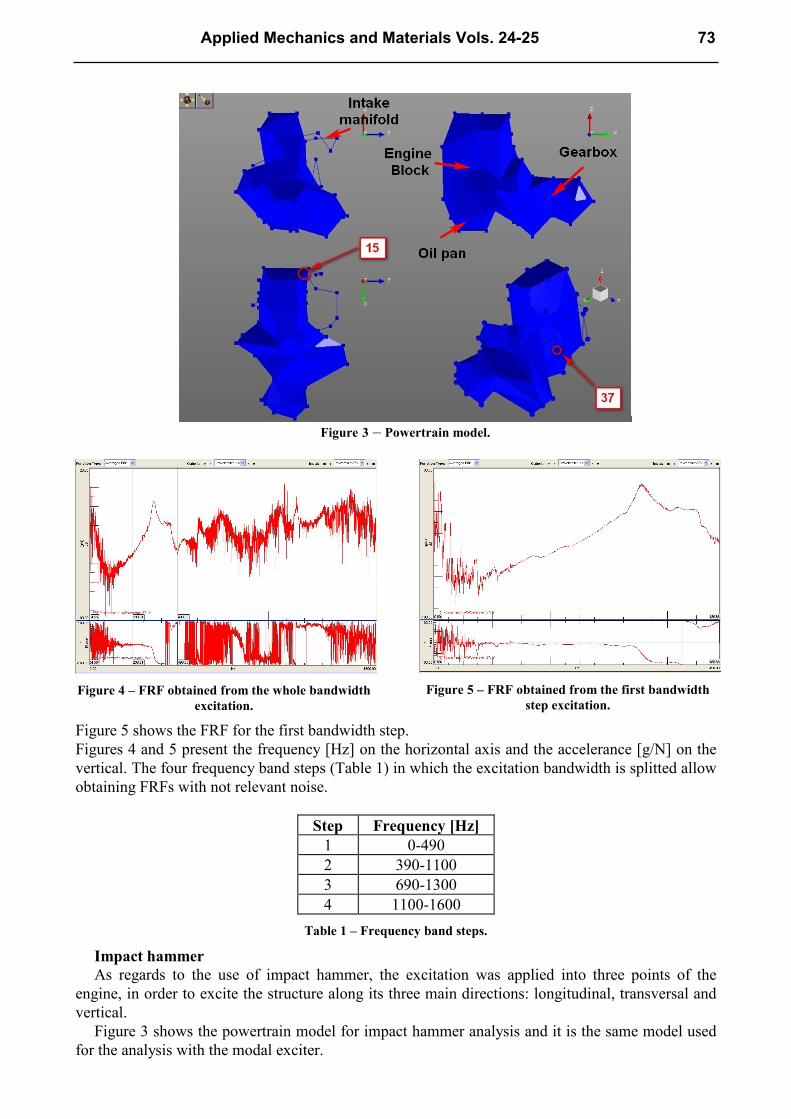
Figure 3 – Powertrain model.
Figure 4 – FRF obtained from the whole bandwidth
excitation.
Figure 5 – FRF obtained from the first bandwidth
step excitation.
Figure 5 shows the FRF for the first bandwidth step. Figures 4 and 5 present the frequency [Hz] on the horizontal axis and the accelerance [g/N] on the vertical. The four frequency band steps (Table 1) in which the excitation bandwidth is splitted allow obtaining FRFs with not relevant noise.
Step Frequency [Hz]
1 0-490 2 390-1100 3 690-1300 4 1100-1600
Table 1 – Frequency band steps.
Impact hammer As regards to the use of impact hammer, the excitation was applied into three points of the
engine, in order to excite the structure along its three main directions: longitudinal, transversal and vertical.
Figure 3 shows the powertrain model for impact hammer analysis and it is the same model used for the analysis with the modal exciter.
Applied Mechanics and Materials Vols. 24-25 73
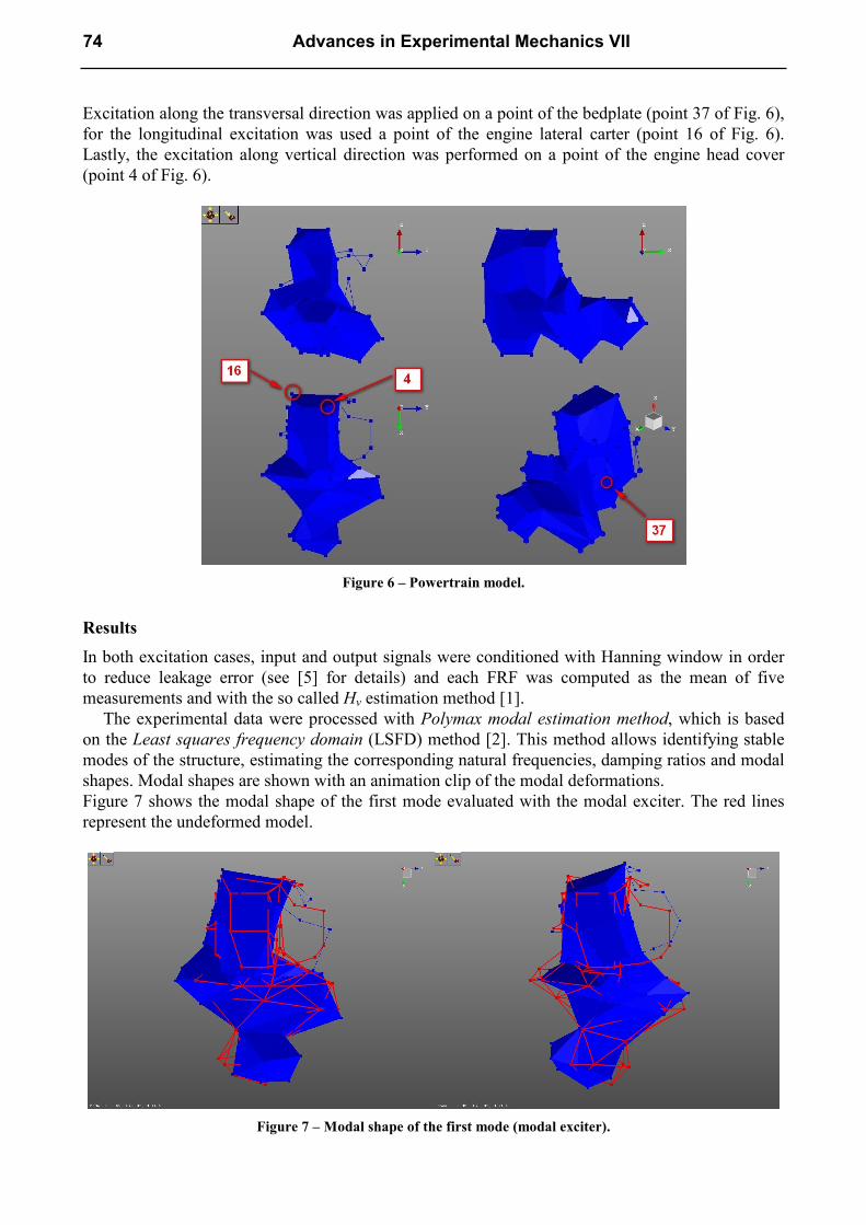
Excitation along the transversal direction was applied on a point of the bedplate (point 37 of Fig. 6), for the longitudinal excitation was used a point of the engine lateral carter (point 16 of Fig. 6). Lastly, the excitation along vertical direction was performed on a point of the engine head cover (point 4 of Fig. 6).
Figure 6 – Powertrain model.
Results
In both excitation cases, input and output signals were conditioned with Hanning window in order to reduce leakage error (see [5] for details) and each FRF was computed as the mean of five measurements and with the so called Hv estimation method [1].
The experimental data were processed with Polymax modal estimation method, which is based on the Least squares frequency domain (LSFD) method [2]. This method allows identifying stable modes of the structure, estimating the corresponding natural frequencies, damping ratios and modal shapes. Modal shapes are shown with an animation clip of the modal deformations. Figure 7 shows the modal shape of the first mode evaluated with the modal exciter. The red lines represent the undeformed model.
Figure 7 – Modal shape of the first mode (modal exciter).
74 Advances in Experimental Mechanics VII
Tables 2 and 3 illustrate the results obtained with the modal exciter and the impact hammer. Mode Frequency
[Hz] Damping ratio [%]
Modal shape
Mode Frequency [Hz]
Damping ratio [%]
Modal shape
1 326 3.14 Bending 1 331 2.96 Bending 2 337 1.30 Bending 2 355 2.35 Bending 3 356 2.05 Bending 3 360 1.66 4 361 1.72 Intake only 4 368 0.18 Bending 5 414 1.66 Torsional 5 415 2.19 Bending 6 453 1.39 6 455 2.00 7 464 1.37 7 474 0.21 8 510 1.52 8 514 0.30
9 522 0.14 Oil pan only
9 567 1.09 10 610 0.14 Torsional 10 605 1.21 11 632 2.02 11 636 3.75 Torsional 12 704 1.63 12 701 1.19 13 734 0.04 Engine only 13 757 1.33 14 745 0.01 Alternator 14 864 0.88 15 753 0.16 15 886 1.44 16 759 1.89 16 1015 0.66 17 830 0.69 17 1133 0.52 18 897 1.01 18 1167 0.52 19 1007 0.28 19 1348 1.08 20 1084 0.35 20 1412 0.18 21 1132 0.71 21 1540 1.24 22 1154 1.01
23 1189 0.28
24 1328 0.87
25 1391 1.64 Engine head
26 1468 2.31
Table 2 – Modal exciter results Table 3 – Impact hammer results
The comparison between the data presented in Tables 2 and 3 shows that it was possible to find a major number of modes using the modal exciter instead of the impact hammer. The difference between the values of natural frequencies of the corresponding modes identified by both excitation strategies is limited to a range of 5 Hz.
Moreover, with the modal exciter it was possible to find a quantity of modes which modal deformation involves only single components (i.e. mode #9 involves only the oil pan); the impact hammer allows identifying only modes which modal deformation involves the whole structure.
Another term of comparison between the two different excitation techniques is offered by the analysis of the identification method parameter called Model size. The Polymax modal estimation method requires that the following relation is respected:
r·�i ≥ 2·� (1)
where r indicates the model size, �i the number of input points and � the number of modes of the structure [2].
It was necessary to set the model size to the value of 60 to apply the identification method to the FRFs obtained from the impact hammer excitation, while it was set to 40 to analyse the data
Applied Mechanics and Materials Vols. 24-25 75
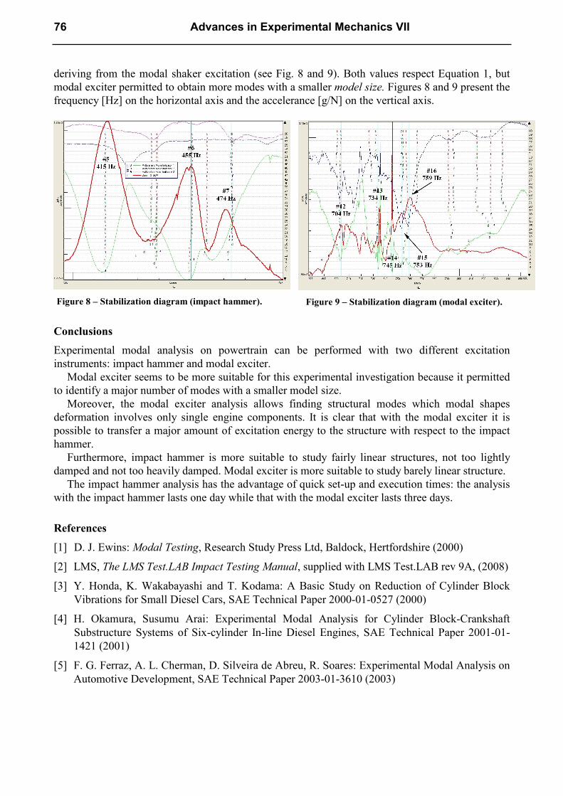
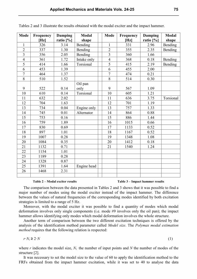
deriving from the modal shaker excitation (see Fig. 8 and 9). Both values respect Equation 1, but modal exciter permitted to obtain more modes with a smaller model size. Figures 8 and 9 present the frequency [Hz] on the horizontal axis and the accelerance [g/N] on the vertical axis.
Figure 8 – Stabilization diagram (impact hammer).
Figure 9 – Stabilization diagram (modal exciter).
Conclusions
Experimental modal analysis on powertrain can be performed with two different excitation instruments: impact hammer and modal exciter.
Modal exciter seems to be more suitable for this experimental investigation because it permitted to identify a major number of modes with a smaller model size.
Moreover, the modal exciter analysis allows finding structural modes which modal shapes deformation involves only single engine components. It is clear that with the modal exciter it is possible to transfer a major amount of excitation energy to the structure with respect to the impact hammer.
Furthermore, impact hammer is more suitable to study fairly linear structures, not too lightly damped and not too heavily damped. Modal exciter is more suitable to study barely linear structure.
The impact hammer analysis has the advantage of quick set-up and execution times: the analysis with the impact hammer lasts one day while that with the modal exciter lasts three days.
References
[1] D. J. Ewins: Modal Testing, Research Study Press Ltd, Baldock, Hertfordshire (2000)
[2] LMS, The LMS Test.LAB Impact Testing Manual, supplied with LMS Test.LAB rev 9A, (2008)
[3] Y. Honda, K. Wakabayashi and T. Kodama: A Basic Study on Reduction of Cylinder Block Vibrations for Small Diesel Cars, SAE Technical Paper 2000-01-0527 (2000)
[4] H. Okamura, Susumu Arai: Experimental Modal Analysis for Cylinder Block-Crankshaft Substructure Systems of Six-cylinder In-line Diesel Engines, SAE Technical Paper 2001-01-1421 (2001)
[5] F. G. Ferraz, A. L. Cherman, D. Silveira de Abreu, R. Soares: Experimental Modal Analysis on Automotive Development, SAE Technical Paper 2003-01-3610 (2003)
76 Advances in Experimental Mechanics VII

Advances in Experimental Mechanics VII 10.4028/www.scientific.net/AMM.24-25
Experimental Modal Analysis of an Automotive Powertrain
10.4028/www.scientific.net/AMM.24-25.71