automotive powertrain control a survey · automotive powertrain control ― a survey jeffrey a....
TRANSCRIPT
AUTOMOTIVE POWERTRAIN CONTROL ― A SURVEY
Jeffrey A. Cook, Jing Sun, Julia H. Buckland, Ilya V. Kolmanovsky,
Huei Peng, and Jessy W. Grizzle
Asian Journal of Control Vol. 8, No. 3, pp. 237-260
September 2006

Asian Journal of Control, Vol. 8, No. 3, pp. 237-260, September 2006 237
Manuscript received March 1, 2005; revised January 2, 2006, accepted May 15, 2006.
Jeffrey A. Cook, Julia H. Buckland and Ilya V. Kol-manovsky are with the Ford Research and Advanced Engi-neering, Dearborn, Michigan 48121, U.S.A.
Jing Sun, Huei Peng and Jessy W. Grizzle are with the Uni-versity of Michigan, Ann Arbor, Michigan, 48109, U.S.A. (e-mail: [email protected]).
AUTOMOTIVE POWERTRAIN CONTROL ― A SURVEY
Jeffrey A. Cook, Jing Sun, Julia H. Buckland, Ilya V. Kolmanovsky, Huei Peng, and Jessy W. Grizzle
ABSTRACT
This paper surveys recent and historical publications on automotive powertrain control. Control-oriented models of gasoline and diesel engines and their aftertreatment systems are reviewed, and challenging control prob-lems for conventional engines, hybrid vehicles and fuel cell powertrains are discussed. Fundamentals are revisited and advancements are highlighted. A comprehensive list of references is provided.
KeyWords: Automotive, powertrain, modeling, control.
I. INTRODUCTION
Modern automobile engines must satisfy challenging and often conflicting requirements. Environmental con-cerns have motivated legislative action by governments around the world to reduce tailpipe emissions. Global commitments to CO2 reduction require improved fuel economy. Customers demand performance and efficiency. All of these objectives must be delivered at low cost and high reliability.
These challenges are being met by modern controls, advanced aftertreatment devices and innovative power-trains. In this paper, we describe approaches to systems engineering, aftertreatment, and control of advanced tech-nology gasoline and diesel engines, hybrid electric power-trains and automotive fuel cells. In each case, fundamental models are discussed and important control problems are illustrated by example. This survey, however, is far from exhaustive and interested readers are encouraged to refer to the proceedings of the recent IFAC workshops on “Ad-vances in Automotive Control” [1-4], the NSF workshop on “Integration of Modeling and Control for Automotive Systems” [5], and the new monograph [6] on the subject.
1.1 A brief history of electronic powertrain control In 1965, the US Congress passed an amendment to the
Clean Air Act providing for the creation and enforcement
of automotive emission standards. This was followed shortly by the establishment of the California Air Re-sources Board and, in 1970, the US Environmental Protec-tion Agency. These regulatory developments spurred major efforts by automotive manufacturers to reduce fuel con-sumption and vehicle emissions, and brought about several technology breakthroughs in the 1970s. That decade saw the introduction of electronic engine control and the de-velopment of key engine control components such as the catalytic converter, exhaust gas recirculation and the com-mon application of electronic fuel injection. Also in the 70s, emission regulations began to be introduced in Europe and Japan. In the 1980s, closed-loop air-fuel ratio control was made possible by the invention of the heated exhaust gas oxygen (HEGO) sensor, and the three-way catalytic con-verter became a standard feature on vehicles in Japan and Europe as well as North America. The 1980s also wit-nessed the increased application of control theory and modeling in the development of automotive powertrain systems. The 1990s defined the “systems” decade for pow-ertrain development. Control intensive engine technologies such as variable valvetrains, direct injection and continu-ously variable transmissions required a multivariable ap-proach to control. At the beginning of the twenty-first cen-tury, with even more stringent emission regulations, tight-ened fuel economy requirements and mandates on green-house gas emissions such as CO2, hybrid electric and fuel cell powertrains appeared as potential solutions to the con-tinued challenges of clean and efficient personal mobility.
1.2 Organization of the paper This paper is organized as follows: in Section 2, mod-
els of the conventional port fuel injection (PFI) gasoline engine and its three-way catalyst (TWC) aftertreatment system are developed and the air-fuel ratio (A/F) control

238 Asian Journal of Control, Vol. 8, No. 3, September 2006
problem is motivated. Important issues in A/F control, to-gether with representative control techniques, are described by reference. Two extensions of the basic engine model are presented for a variable cam timing engine and a turbo-charged engine with electronically controlled wastegate.
Section 3 addresses modeling and control of direct in-jection stratified charge (DISC) gasoline engines. In this section, a DISC engine model and its lean NOx trap (LNT) aftertreatment system are described, and unique control problems due to the hybrid nature of the engine are pre-sented. The problems of mode transition control, LNT ad-aptation, and fuel economy-emission tradeoffs are ad-dressed. A computationally efficient dynamic programming solution is described to guide the DISC system design.
Section 4 covers modeling and control of diesel en-gines. Diesel engine controls, while they share some com-mon features with gasoline engines, have many unique advantages and challenges. Several unique diesel control issues including sensor configuration, subsystem coordina-tion and aftertreatment technology are reviewed in this section.
Sections 5 and 6 are devoted to hybrid and fuel cell powertrain systems. For fuel cell based automotive power-train systems, the control of reactant supply, humidity and temperature are highlighted. For hybrid vehicles, different system architecture and associated control issues are re-viewed, together with methodologies and tools for control strategy development. In both sections, references are given in lieu of the model description, due to the space limit.
II. PORT FUEL INJECTION ENGINE CONTROL
In the conventional PFI gasoline engine, fuel is me-tered to form a homogeneous and generally stoichiometric mixture based on measurements of inlet air flow or intake manifold pressure, and injected into the intake port of each cylinder upstream of the intake valve. Emission control relies primarily on a three way catalyst system to convert the HC, CO, and NOx emissions in the exhaust. This sys-tem may consist of several TWCs with different precious metal formulations (Pt and/or Pd, generally) and locations in the exhaust system to optimize emissions performance. It is characteristic of the three-way catalytic converter that high simultaneous conversion efficiencies for the three species occur only in a narrow band around stoichiometry, emphasizing the criticality of A/F control to minimizing tailpipe emissions. An overview of the challenges related to emissions control in the design and development of power-train control systems for modern passenger vehicles may be found in [7].
Considerable effort as well is made to minimize en-gine out emissions to reduce the amount of costly precious metal required in the TWC. Typically, NOx reduction is
accomplished by reducing combustion temperature through exhaust gas recirculation (EGR). EGR can be introduced externally via a valve that connects the intake and exhaust manifolds, or internally via variable camshaft timing (VCT) control. VCT can improve fuel economy in addition to reducing emissions, but presents control challenges that arise from dynamic interactions in the engine breathing process.
Turbocharged engines present similar challenges. The torque developed by a conventional gasoline engine is proportional to the air supplied to the cylinders, because the A/F is controlled to stoichiometry. In a turbocharged en-gine, the density of the cylinder air charge is increased. Consequently, engine displacement may be reduced at equivalent power, providing improvements to CO2 emis-sions and fuel economy. To achieve these benefits in a modern engine requires coordinated control of the throttle and wastegate actuators.
The following subsection will provide a brief review of models for the PFI engine and the TWC aftertreatment system. Control problems for A/F regulation, VCT torque management, and turbocharged gasoline engines will also be discussed.
2.1 PFI engine and aftertreatment models A great deal of literature over many years describes
the development of “control oriented” engine models: that is, linear and nonlinear low frequency phenomenological representations that capture the essential system dynamics required for control development, along with key static behavior such as emissions and volumetric efficiency that may be obtained experimentally from steady state mapping on an engine dynamometer. The four-stroke engine cycle naturally divides the physical process into four events comprising intake, compression, power generation and exhaust. This hybrid (that is, discrete event plus continuous dynamics) nature of the system is typically captured in the model by crank-angle based sampling. An introduction to engine modeling may be found in [6].
2.1.1 The fundamental PFI engine model The mathematical representation of the conventional,
naturally aspirated engine includes the following elements: (1) the throttle body, (2) the intake manifold, (3) torque generation and (4) engine rotational dynamics. The model may also include the EGR system, exhaust gas temperature and pressure dynamics, and feedgas emissions. The intake manifold dynamics are derived from the ideal gas law:
( )i a egr cyli K W W WP = + − (1)
where Ki depends on the intake manifold volume and tem-perature, Wa, Wegr are the mass flow rates through the throt-tle body and the EGR valve respectively; and Wcyl is the mean value of the flow rate at which the charge is inducted into the cylinders. The flows through the throttle body and

J. A. Cook et al.: Automotive Powertrain Control ⎯ A Survey 239
EGR valve are represented by a standard orifice equation:
egr eth a i ia egr
a ea e
A PA P P PW WP PT T
⎛ ⎞ ⎛ ⎞= φ , = φ⎜ ⎟ ⎜ ⎟
⎝ ⎠ ⎝ ⎠ (2)
where Ath, Aegr are the effective flow areas for the throttle body and EGR valve respectively; Pi, Pe, and Pa are intake manifold, exhaust manifold and ambient pressures; Ta and Te are the ambient and exhaust temperatures. The function φ represents the effects of the pressure ratio on the flow across the valve:
12( 1) 1
12
12 111
2 2if1 1
( )2 21 if
1 1
x
x
x x x
+− −
−−γ⎧ ⎫⎡ ⎤⎪ ⎪⎢ ⎥⎨ ⎬⎢ ⎥⎪ ⎪⎣ ⎦⎩ ⎭
⎧ ⎛ ⎞ ⎛ ⎞⎪ ≤⎜ ⎟ ⎜ ⎟⎪ + +⎝ ⎠ ⎝ ⎠⎪φ = ⎨⎪ ⎛ ⎞− >⎪ ⎜ ⎟− +⎪ ⎝ ⎠⎩
γ γγ γ
γγγ
γ
γγ γ
γγ γ
(3)
where γ is the ratio of specific heats, which takes different values for Wa and Wegr.
The amount of charge inducted into the cylinders, Wcyl, is a function of engine speed, intake manifold pressure and, possibly, temperature, where intake manifold temperature depends on mass air flow and EGR. Wcyl is generally rep-resented as a static regression equation based on steady- state mapping data for a particular engine.
Engine rotational dynamics follow the equation:
30 e b lJ Nπ = −T T (4)
where Tb, Tl are the engine brake and load torque in Nm, respectively, and the factor π/30 is due to the unit conver-sion of engine speed, N, (from rpm to rad/sec). The engine brake torque, Tb, is the net torque available on the crank-shaft to drive the rest of the powertrain, and can be de-composed into:
b i f= −T T T , (5)
where Ti is the indicated torque, a measure of the total torque delivered to the piston by burning the fuel and Tf is the total friction which the engine has to overcome when delivering the torque to the crankshaft. The friction torque includes the pumping losses during the intake and exhaust strokes plus mechanical friction and may be regressed as a function of engine speed and intake manifold pressure. Brake torque is generally represented as a regressed func-tion of Wcyl, A/F, N, and ignition timing.
2.1.2 Three-way catalyst model Control oriented models of the TWC generally incor-
porate two parts: an oxygen storage mechanism to account for the modification of the feedgas A/F as it passes through the catalyst, and the standard steady-state efficiency curves
driven by the tailpipe A/F computed from the oxygen stor-age model [8-11]. The following model is taken from [8].
First, consider the oxygen storage sub-model. Let 0 ≤ Θ ≤ 1 be the fraction of oxygen storage sites occupied in the catalyst. Θ is also referred to as the TWC oxygen load-ing. The oxygen storage mechanism is then modeled as a limited integrator:
1 1( )0 23 ( ) 1 0 1( )
0 otherwise
FG aa FG
W tC W
⎧ ⎛ ⎞ρ λ , Θ . − τ − ≤ Θ ≤⎪ ⎜ ⎟λΘ = ⎨ ⎝ ⎠
⎪⎩
(6)
where Wa denotes the mass air flow rate, used to approxi-mate the flow rate of the mixture entering the TWC and τ is used to account for the transport delay. C represents the effective catalyst “capacity,” or the volume of active sites for oxygen storage, expressed in terms of the mass of oxy-gen that can be stored in the catalyst, as a function of Wa; ρ describes the exchange of oxygen between the exhaust gas and the catalyst; and λ denotes the relative air-fuel ratio, with stoichiometry at λ = 1 (the subscript FG refers to the feedgas).
The effective TWC volume parameter, C, is expressed as a function of Wa in order to account for an observed increase in effective volume at high flow rates, specifically above 10g/s. For clarity, it should be emphasized that C does not represent the physical volume of the catalyst, of-ten sized according to the engine displacement. For exam-ple, if there were no usable storage sites (i.e., if they were poisoned by substances such as sulfur or phosphorus), then C would be zero.
The oxygen storage function ρ is modeled as
( ) 1( )
( ) 1L L FG
FGR R FG
ff
α Θ λ >⎧⎪ρ λ , Θ = ,⎨α Θ λ <⎪⎩ (7)
with 0 ≤ fL ≤ 1 representing the fraction of oxygen from the feedgas attached to a site in the catalyst, and 0 ≤ fR ≤ 1 rep-resenting the fraction of oxygen being released from the catalyst and recombining with the feedgas. In the oxygen storage function, fL and fR vary with the TWC oxygen loading and potentially with the space velocity (that is, the feedgas volumetric flow rate divided by the catalyst vol-ume). In the model, fL is assumed to be monotonically de-creasing, with value one at Θ = 0 and zero at Θ = 1, and fR is assumed to be monotonically increasing, with value zero at Θ = 0 and one at Θ = 1.
The quantity 0.23 × Wa × ( )11FG
− λ represents the dif-
ferential total mass of oxygen in the feedgas with respect to stoichiometry. When multiplied by ρ, it gives the mass of oxygen that is deposited in (or released from) the catalyst. By conservation of mass, the resulting equivalent tailpipe A/F can be directly computed:
240 Asian Journal of Control, Vol. 8, No. 3, September 2006
( ) ( 1)TP FG FG FG= − ρ , Θ × − .λ λ λ λ (8)
2.2 A/F control for PFI engines Three main problems arise in A/F control of the con-
ventional PFI engine: accurate estimation of air charge, compensation for fuel puddling dynamics in the intake manifold runners and precise regulation of closed-loop A/F for good catalyst performance. A low frequency model of the induction process is described in [12], and compensa-tion is developed for the relatively slow dynamics of the conventional hot-wire anemometer used to measure inlet air flow. Transient fuel characteristics for a PFI engine were first reported by Fozo and Aquino in [13]. In [14], a method of adaptive transient compensation for fuel wall-wetting dynamics is described that accounts for vary-ing fuel properties. The technique requires only a heated exhaust gas oxygen (HEGO) sensor, which remains the prevalent feedback sensor for closed-loop A/F control. A HEGO sensor is essentially a switch, indicating that the A/F mixture is either rich or lean of stoichiometry, but not by how much. The basic idea of [14] is to use the feedback signal to evaluate changes in A/F during driver induced transients in closed loop, and store corrections to the com-pensation algorithm indexed by engine temperature for use in the next transient or during open-loop cold start opera-tion.
In [15], it was shown that cylinder-to-cylinder A/F differences result in a closed-loop lean shift in controlled A/F due to preferential diffusion of H2 and CO across the HEGO sensor upstream of the catalyst. This control-point shift causes a dramatic reduction in NOx conversion effi-ciency due to the precipitous nature of the TWC character-istic away from stoichiometry. Typically, this effect is mitigated by biasing the A/F setpoint slightly rich, at a cost in fuel economy and conversion efficiency of the other exhaust constituents. In [16], an approach to achieving uniform cylinder-to-cylinder A/F control for a 4-cylinder engine in the presence of injector mismatch and unbalanced air flow due to engine geometry is presented. The method recognizes that the individual cylinder representation of the fueling process describes a periodically time varying sys-tem due to the unequal distribution of A/F from cylinder to cylinder. The key features of the controller are the con-struction of a time-invariant representation of the process and event-based sampling and feedback. In [17], the method was extended to an 8-cylinder engine in which exhaust manifold mixing dynamics were significant.
A significant advancement in A/F feedback control capability is the introduction in production vehicles of the Universal Exhaust Gas Oxygen (UEGO) sensor. Unlike the conventional HEGO sensor which simply switches about stoichiometry, the UEGO is a linear device that permits an actual measurement of A/F [18]. Control and diagnosis of catalysts using UEGO sensors is described by [19,20]. In [21], Fiengo and co-authors use the catalyst model de-
scribed above along with pre- and post-catalyst UEGO sensors to develop a controller with two objectives: to si-multaneously maximize the conversion efficiencies of HC, CO and NOx, and to obtain steady-state air-fuel control that is robust with respect to disturbances.
2.3 Control of engines with variable cam timing Variable cam timing provides improved performance
and reduced feedgas emissions using an electro-hydraulic mechanism to rotate the camshaft relative to the crankshaft and retard cam timing with respect to the intake and ex-haust strokes of the engine. In this manner, the amount of residual gas trapped in the cylinder at the end of the ex-haust stroke is controlled, suppressing NOx formation [22-24]. In addition, VCT allows the engine designer to optimize cam timing over a wide range of engine operating conditions, providing both good idle quality (minimal overlap between the intake and exhaust events) and im-proved wide-open throttle performance (maximum in-ducted charge). Obviously, variable cam timing has a sub-stantial effect on the breathing process of the engine. Prop-erly controlled, the variable cam can be used to operate the engine at higher intake manifold pressures, reducing pumping losses at part throttle conditions to provide a fuel economy improvement. Uncompensated, however, VCT acts as a disturbance to the breathing process, compromis-ing drivability and substantially reducing its effectiveness in reducing emissions.
Four versions of VCT are available: phasing only the intake cam (intake only), phasing only the exhaust cam (exhaust only), phasing the intake and exhaust cams equally (dual equal), and phasing the two camshafts inde-pendently (dual independent). A low order nonlinear model of a dual-equal VCT engine is derived in [25]. In [26], the model forms the basis for active compensation of VCT induced cylinder air charge variation employing electronic throttle control (ETC). The balance of this section will re-view the VCT model and describe the ETC compensation.
The basic equations of the VCT engine model are the same as those in Section 2.1, modified to incorporate the effects of the cam actuator on engine breathing. For the VCT engine, the mass air flow rate into the cylinders is represented as a function of cam phasing, ζcam, in addition to manifold pressure, Pi, and engine speed, N:
( )cyl i camW F N P= , , ζ (9)
which, for the design model of [26], is approximated by a function affine in Pi:
1 2( ) ( )cyl cam i camW N P N= α , ζ + α , ζ (10)
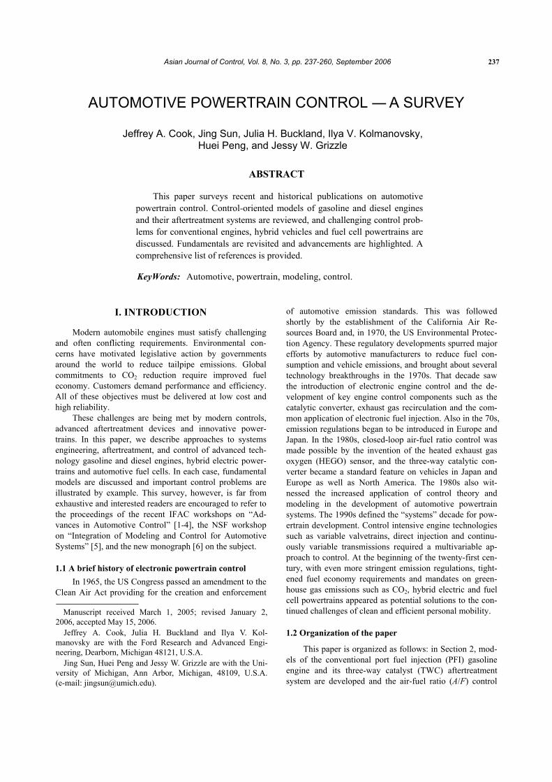
where α1 and α2 are low-order polynomials in N and ζcam. A block diagram of the VCT engine is illustrated in
Fig.1, which shows the cam timing reference, ζref, sched-uled on engine speed and driver demanded throttle position, θ0. Typically, the cam schedule reaches maximal cam re-
J. A. Cook et al.: Automotive Powertrain Control ⎯ A Survey 241
tards at part throttle to provide maximal internal EGR; close to idle and at wide open throttle, the cam phasing is at zero or slightly advanced. Scheduling cam on throttle causes it to change when the pedal is depressed or released. It is this torque variation caused by the cam transient that results in undesirable engine response and drivability prob-lems. Note that the throttle angle is comprised of the throt-tle position due to the driver’s request (θ0) and an additive term due to the compensation (θ*),
0∗θ = θ + θ .
The throttle flow equation is represented as functions of pressure and flow geometry, φ(Pi)g(θ), as in the conven-tional engine model.
A feedforward compensator is designed to recover the drivability of the conventional engine by eliminating the effect of the cam transients on cylinder mass air flow. The algorithm employs θ* as a virtual actuator, according to [26]. That is, a control law is developed for θ* such that the rate of change of Wcyl coincides with that of the conven-tional engine. Specifically, compensation θ* is evaluated:
1 21
0 01
( )( ) ,
( ) ( )cam cami i
cami i i
P Pg gK P P
∂α ∂α∂ζ ∂ζ∗ −
⎛ ⎞+ φ⎜ ⎟θ = + θ − θζ⎜ ⎟φ α φ⎝ ⎠
(11)
where iP is a fictitious reference manifold pressure which should be equal to the manifold pressure of the conven-tional engine driven with the throttle angle, θ0, and engine speed, N. This reference manifold pressure is generated by
( )0 1 2( ) ( ) ( 0) ( 0)i i ii K g N NP PP = φ θ − α , − α , . (12)
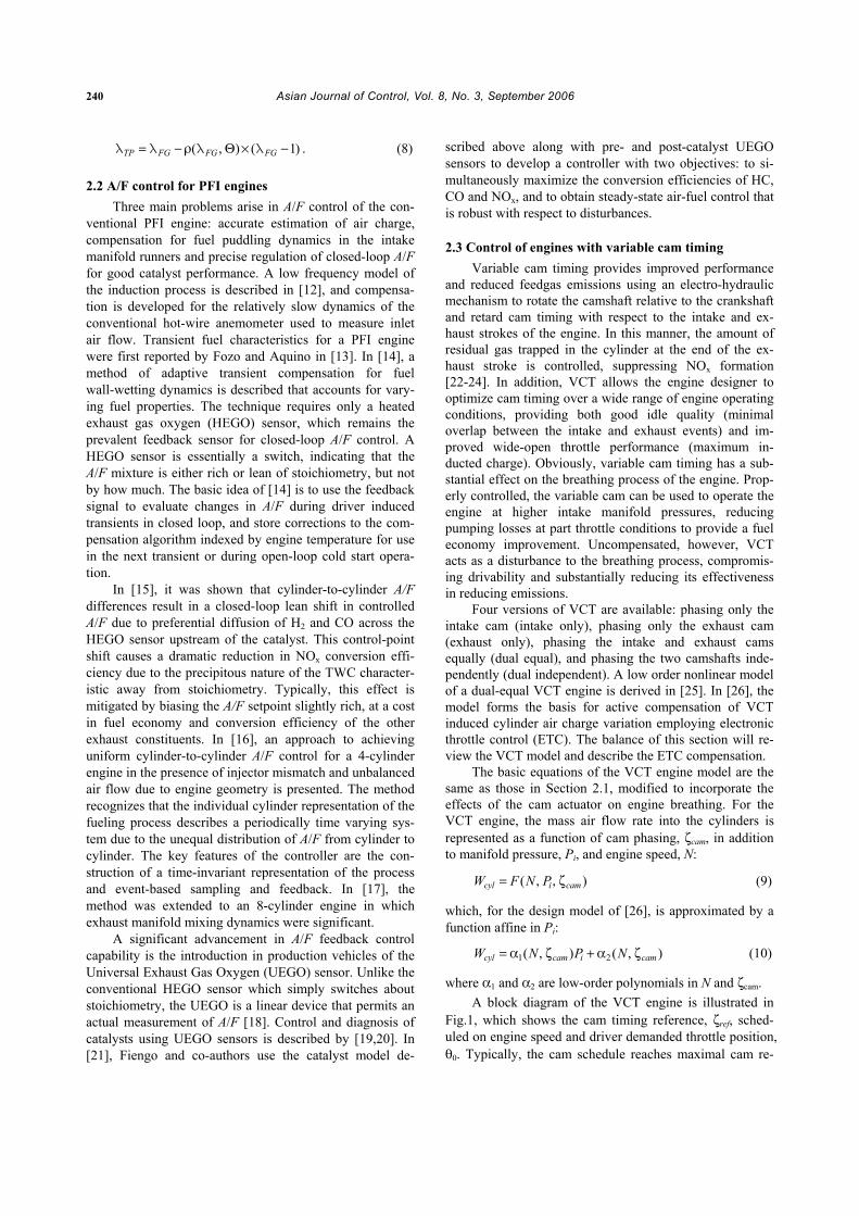
Figure 2 shows the reduction of the torque fluctuation during cam transients achieved by the compensation.
2.4 Control of turbocharged gasoline engines Turbocharging is an efficient method to boost intake
pressure, as it extracts energy from the exhaust gases to drive a compressor to pressurize ambient air. In automotive appli-cations, operating conditions vary over a wide range of speed and load. A design challenge is to develop a system that pro-vides adequate boost at low speed and load without creating an over-boost situation at high speed and loads [27]. Typi-cally, the amount of boost delivered by a turbocharger is controlled by a wastegate.1 In any event, the advantages of turbocharging are accompanied by an increase in complexity of the control design and calibration.
Fig. 1. Engine model with VCT and electronic throttle.
Fig. 2. Torque response of the VCT engine to cam phasing
steps with and without compensation.
Complexity is also introduced by other phenomena associated with turbocharging. For example, increasing charge density increases propensity for engine knock, par-ticularly at high loads. This phenomenon is alleviated in many applications by passive or active thermal manage-ment with a charge cooling device, such as an intercooler. In conventional gasoline engines, knock is further con-trolled by spark retard [29]. In direct injection engines, fuel injection control may also provide some benefit [28].
Transient response is another factor, as turbocharger inertia leads to a phenomenon known as “turbo lag.” Turbo lag describes the delay in torque response due to the time required for the turbocharger to change speed and thus affect boost pressure. Control objectives for fast response to minimize this effect are tempered by limits on boost pressure overshoot, which can lead to unacceptable torque disturbances [30,31].
Modern turbocharged gasoline engines have advanced technology actuators such as electronic throttle and variable valve timing, in addition to the wastegate. Coordinated con-trol of these actuators is critical to achieve the full benefit of these combined technologies. Historically, literature that pertains to wastegate control in gasoline applications, such as [32,33,29], refer to systems with a mechanical throttle.
1 Other advanced technology devices, for example variable geometry turbochargers that directly control turbine or compressor flow are under development by automotive suppliers [28]. Such devices have had application in diesel engines but are currently unsuitable for the high exhaust temperature environment of gasoline engines.
242 Asian Journal of Control, Vol. 8, No. 3, September 2006
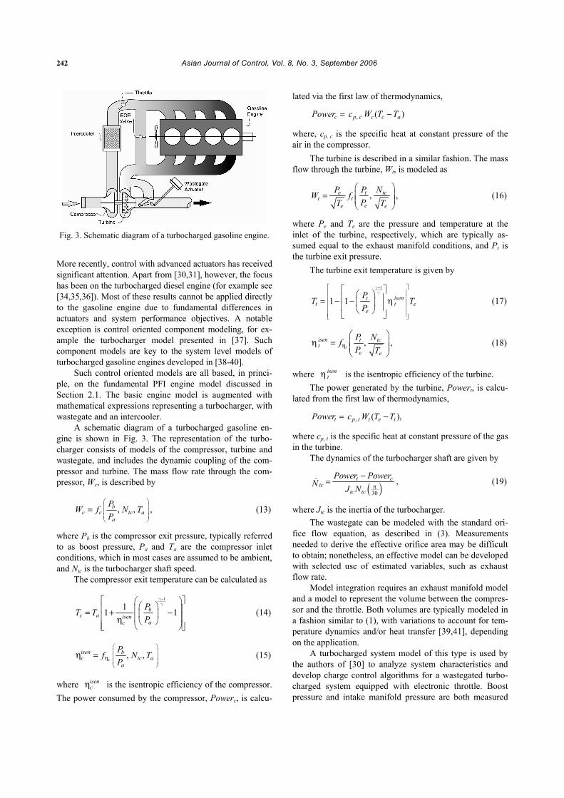
Fig. 3. Schematic diagram of a turbocharged gasoline engine.
More recently, control with advanced actuators has received significant attention. Apart from [30,31], however, the focus has been on the turbocharged diesel engine (for example see [34,35,36]). Most of these results cannot be applied directly to the gasoline engine due to fundamental differences in actuators and system performance objectives. A notable exception is control oriented component modeling, for ex-ample the turbocharger model presented in [37]. Such component models are key to the system level models of turbocharged gasoline engines developed in [38-40].
Such control oriented models are all based, in princi-ple, on the fundamental PFI engine model discussed in Section 2.1. The basic engine model is augmented with mathematical expressions representing a turbocharger, with wastegate and an intercooler.
A schematic diagram of a turbocharged gasoline en-gine is shown in Fig. 3. The representation of the turbo-charger consists of models of the compressor, turbine and wastegate, and includes the dynamic coupling of the com-pressor and turbine. The mass flow rate through the com-pressor, Wc, is described by
bc c tc a
a
PW f N TP
⎛ ⎞⎜ ⎟⎜ ⎟⎜ ⎟⎝ ⎠
= , , , (13)
where Pb is the compressor exit pressure, typically referred to as boost pressure, Pa and Ta are the compressor inlet conditions, which in most cases are assumed to be ambient, and Ntc is the turbocharger shaft speed.
The compressor exit temperature can be calculated as
1
11 1bc a isen
ac
PT TP
−⎡ ⎤⎛ ⎞⎛ ⎞⎢ ⎥⎜ ⎟= + −⎜ ⎟⎢ ⎥⎜ ⎟η ⎝ ⎠⎢ ⎥⎝ ⎠⎣ ⎦
γγ
(14)
c
isen bc tc a
a
Pf N TP
⎛ ⎞⎜ ⎟⎜ ⎟η⎜ ⎟⎝ ⎠
η = , , (15)
where isencη is the isentropic efficiency of the compressor.
The power consumed by the compressor, Powerc, is calcu-
lated via the first law of thermodynamics,
cPower = ( )p c c c ac W T T, −
where, cp, c is the specific heat at constant pressure of the air in the compressor.
The turbine is described in a similar fashion. The mass flow through the turbine, Wt, is modeled as
e t tct t
ee e
P P NW fPT T
⎛ ⎞= , ,⎜ ⎟⎜ ⎟
⎝ ⎠ (16)
where Pe and Te are the pressure and temperature at the inlet of the turbine, respectively, which are typically as-sumed equal to the exhaust manifold conditions, and Pt is the turbine exit pressure.
The turbine exit temperature is given by
1
1 1 isentt t e
e
PT TP
−⎡ ⎤⎢ ⎥⎢ ⎥⎢ ⎥⎢ ⎥⎢ ⎥⎣ ⎦
⎡ ⎤⎛ ⎞⎢ ⎥= − − η⎜ ⎟⎢ ⎥⎝ ⎠⎣ ⎦
γγ
(17)
t
isen t tct
e e
P NfP Tη
⎛ ⎞η = , ,⎜ ⎟⎜ ⎟
⎝ ⎠ (18)
where isentη is the isentropic efficiency of the turbine.
The power generated by the turbine, Powert, is calcu-lated from the first law of thermodynamics,
tPower = ( )p t t e tc W T T, − ,
where cp, t is the specific heat at constant pressure of the gas in the turbine.
The dynamics of the turbocharger shaft are given by
( )30
t ctc
tc tc
Power PowerN J N π
−= , (19)
where Jtc is the inertia of the turbocharger. The wastegate can be modeled with the standard ori-
fice flow equation, as described in (3). Measurements needed to derive the effective orifice area may be difficult to obtain; nonetheless, an effective model can be developed with selected use of estimated variables, such as exhaust flow rate.
Model integration requires an exhaust manifold model and a model to represent the volume between the compres-sor and the throttle. Both volumes are typically modeled in a fashion similar to (1), with variations to account for tem-perature dynamics and/or heat transfer [39,41], depending on the application.
A turbocharged system model of this type is used by the authors of [30] to analyze system characteristics and develop charge control algorithms for a wastegated turbo-charged system equipped with electronic throttle. Boost pressure and intake manifold pressure are both measured
J. A. Cook et al.: Automotive Powertrain Control ⎯ A Survey 243
and conventional decentralized PI control with feedforward on the wastegate is used to regulate these measured vari-ables to desired setpoints, which are chosen to achieve fuel economy, emissions and driveability objectives. This ap-proach produces acceptable performance, however the wastegate is prone to saturation. Multivariable control techniques can be used to analyze the system to guide for-mulation of a modified controller that maintains a simple structure desirable for implementation, and yet benefits from a centralized control methodology. Such an approach is described in [42].
III. LEAN BURN AND DIRECT INJECTION GASOLINE ENGINE CONTROL
Lean-burn engines may be a major enabling technol-ogy for improving fuel economy of gasoline engines. En-gines operated with lean mixtures have lower throttling losses at low and part loads, resulting in reduced (up to 15%) fuel consumption and CO2 generation. The major technical hurdles in extending the lean-burn limit of a PFI engine are combustion stability and NOx treatment. While the lean limit of a conventional PFI engine has been sig-nificantly extended by advanced combustion concepts (such as those that induce high turbulence), the maximum A/F that can be achieved in PFI engines without compro-mising other performance indices is around 22. This limit is substantially extended by direct injection and stratification made possible by technical advances in high-pressure fuel injection and combustion chamber design. The issues of NOx emissions associated with lean-burn (port or direct injected) engines arise because of the fact that conventional three-way catalysts are ineffective for air-fuel ratios even slightly lean of stoichiometry. Consequently, lean-burn engines use an actively controlled emission device called a lean NOx trap (LNT) to meet NOx emission standards. The incorporation of the LNT adds both cost and complexity, making optimization and trade-off analysis the predomi-nant tasks for control and integration of lean-burn gasoline engine systems.
In this section, we will focus on three main control problems for direct injection stratified charge (DISC) en-gines equipped with LNT: mode transition, aftertreatment control and adaptation, and system optimization and inte-gration. While the port fuel injected lean burn engine con-trol problems will not be explicitly addressed here, it should be noted that the issues and solutions for direct in-jection engines are applicable to PFI lean-burn engines as well, with minor modification.
3.1 Unique features and control implications of DISC powertrain system A DISC engine, like a diesel, injects fuel directly into
the combustion chamber. It is different from a conventional PFI engine discussed in Section 2 in several respects. Most
importantly, the DISC engine can, depending on speed and load, operate in one of three combustion modes: homoge-neous stoichiometric (A/F ≈ 14.64), homogeneous lean (between stoichiometry and about 20) or stratified (≥ 20). A homogeneous A/F mixture is achieved by injecting fuel early in the intake stroke, while stratification is achieved by injecting late, during the compression stroke [43]. The torque and emission characteristics corresponding to ho-mogeneous and stratified operation are so distinct that dif-ferent control strategies are required to optimize perform-ance in the two regimes [44,45]. Note also that, in addition to the usual control variables such as throttle position, igni-tion timing, exhaust gas recirculation (EGR) and fueling rate, the DISC engine requires new inputs including injec-tion timing, fuel rail pressure and swirl control at a mini-mum [46]. Finally, the ultra-lean A/F operation of the di-rect injection engine mandates the use of a lean NOx trap (LNT) to manage oxides of nitrogen emissions. The LNT, as a NOx storage device, needs to be purged periodically to regenerate its storage capacity.
These special features of DISC engine operation have important control implications and lead to the following unique control problems:
• Mode transition: Depending on engine operating and LNT loading conditions, the DISC engine will either operate in stratified or homogeneous mode or switch between the two modes. The control must be capable of changing the combustion mode and the air-fuel ra-tio of the engine rapidly without causing noticeable disturbance to the driver.
• Aftertreatment control: The requirements for the after-treatment control include (1) periodically running the engine rich of stoichiometry to regenerate its trap ca-pacity, (2) dealing with the sulphur poisoning problem to maintain its efficiency, and (3) assuring that the LNT operates within its temperature window to main-tain high efficiency and to avoid thermal degradation.
• Optimization and trade-off analysis: The inclusion of the storage device in the aftertreatment system changes the nature of the optimization problem. The interactive characteristics of the subsystems involved, together with the time and trajectory dependent nature of LNT operation, result in a high dimensional and dynamic optimization problem that demands new computational methodologies and tools.
The engine and aftertreatment models, to be discussed in the following subsection, facilitate the model-based treatment of these problems.
3.2 DISC engine and its aftertreatment system models 3.2.1 DISC engine model
References [44,45] describe modeling and control of a direct injection stratified charge (DISC) gasoline engine and discuss the fundamentally hybrid nature of the system. This model is illustrated in Fig. 4. On the surface, the model structure is not dissimilar to a conventional PFI

244 Asian Journal of Control, Vol. 8, No. 3, September 2006
Fig. 4. Block diagram of DISC engine model.
engine discussed in Section 2, consisting of the throttle, intake manifold dynamics, engine pumping, torque genera-tion, rotational inertia and feedgas emissions. In fact, many of the equations used to describe the PFI engines in Section 2 can be applied here. Because of the different characteris-tics for homogeneous and stratified operation, the model is, in fact, hybrid in the sense that most components are rep-resented by two continuous-variable sub-models with a discrete switching mechanism to select the appropriate characterization based on injection timing. Additionally, the injection-to-torque delay, fundamentally associated with the four-stroke engine cycle (intake-compression- power-exhaust), becomes a function not only of engine speed, but also of the operating mode that dictates the rela-tionship between the injection and combustion events.
3.2.2 Lean aftertreatment model The typical aftertreatment system for a lean-burn en-
gine with a commonly used sensor configuration is shown in Fig. 5. It consists of a conventional three-way catalytic converter (usually closely coupled to the engine for optimal cold start performance) and an underbody LNT, with oxy-gen and temperature sensors in various locations.
The key chemical reactions involved in the LNT op-eration can be briefly discussed as follows. NOx storage phase: under lean conditions, NO is oxidized in the gas phase and the resulting NO2 is then adsorbed on storage sites such as barium nitrate. As the NOx stored in the LNT increases, the storage efficiency drops and the trap must be purged to regenerate its capacity. LNT purge phase: under rich conditions, the barium nitrate becomes thermody-namically unstable and releases NO2 and BaO. BaO then combines with CO2 in the exhaust to form BaCO3, thereby regenerating the storage sites. The released NOx is con-verted to N2 over the precious metal sites by reductants (CO or H2) in the engine exhaust stream.
A control oriented representation of the LNT exhaust aftertreatment system was first developed in [47]. In this model, the amount of NOx stored on the LNT is a state. Under lean conditions, the NOx storage capability is mod-eled by a limited integrator with the storage rate of NOx being a monotonically decreasing function of the state of the integrator.
Fig. 5. Aftertreatment system schematic: components and
sensor locations.
In [48], the model is extended by modifying the purge model to capture the interactions between the oxygen stor-age and NOx storage mechanisms in the LNT. By sepa-rately modeling the releasing and conversion reactions during the purge phase, the integrated model is able to rep-licate experimentally observed NOx spikes during the purge phase [49]. In another modification to the original model, air-fuel ratio, λ, is used instead of WCO, in in the functions that represent the NOx release rate and conversion effi-ciency, making the model more amenable to control im-plementation.
3.3 Mode transitions for DISC engine control Typically, stratified operation is limited to low- and
part-load engine operating conditions where the maximum fuel economy benefits of a DISC engine can be achieved. At increasing loads, stratified combustion often results in increased smoke and hydrocarbon emissions, requiring a switch to homogeneous operation. Similarly, as the engine speed increases, a mode switch is also necessary as the time for mixing and breathing is reduced, making it infea-sible to operate in stratified mode (stratified operation re-quires more air charge). Finally, the LNT aftertreatment system needs to be purged periodically to maintain high efficiency, and this is accomplished by transitioning to an air-fuel ratio slightly rich of stoichiometry. Consequently, mode switching between stratified and homogeneous combustion may be initiated not only when the engine torque demand increases, but also when the torque demand is small and constant, such as when the engine is idling. The mode transitions have to be accomplished in a manner that does not create a disturbance noticeable by the driver, while providing the desired value of the engine torque
J. A. Cook et al.: Automotive Powertrain Control ⎯ A Survey 245
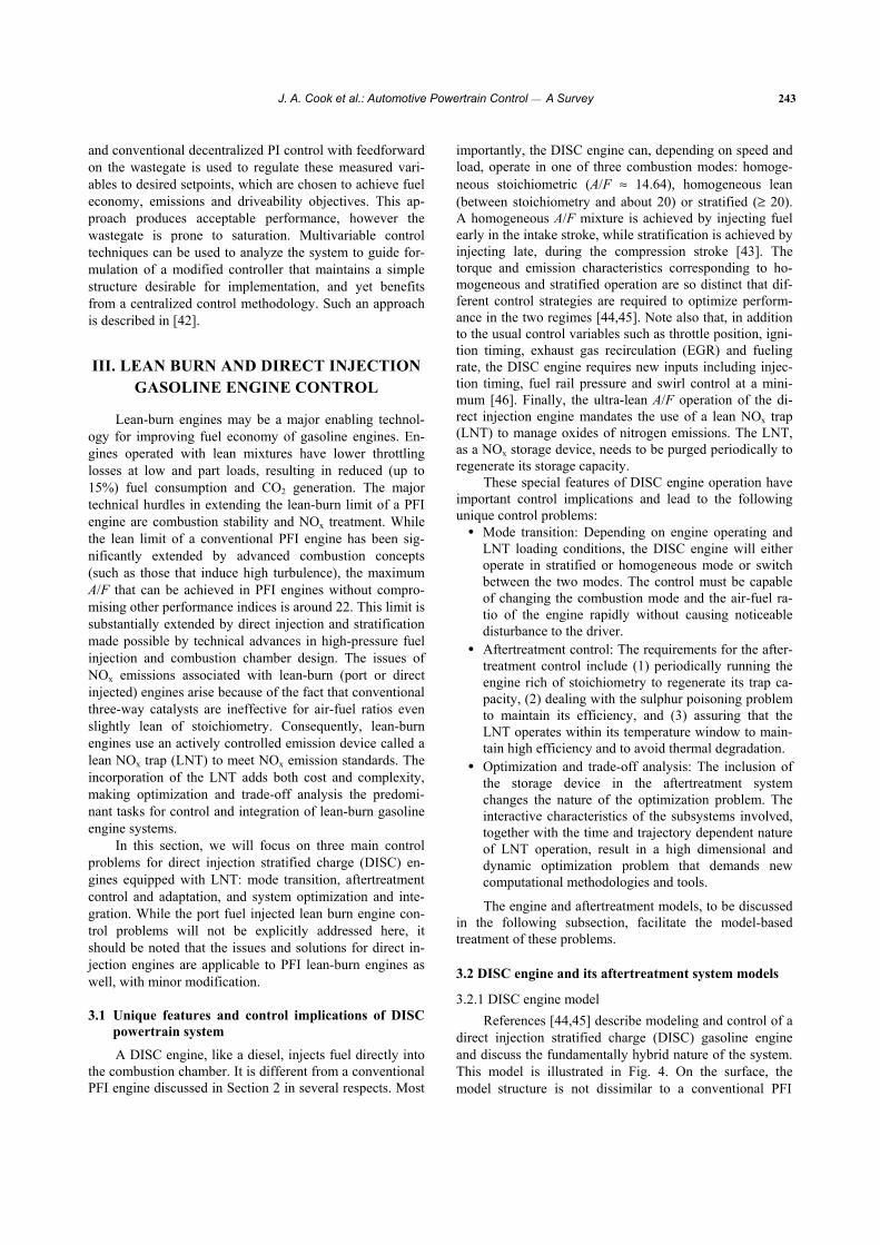
throughout the transition. In [50], a hybrid control scheme is presented to manage the transition. The controller con-sists of a high level Transition Governor that is used to determine the combustion mode and the setpoints, and a low level feedback controller that coordinates the spark timing, throttle, and fuel injection to ensure the desired value of the engine torque throughout the transition. In [45], the coordinating control is derived by minimizing the cost function that incorporates performance indices for torque delivery, charge control, spark control and EGR delivery, with the weighting for each individual performance index adjusted according to the desired mode of operation. Figure 6 shows typical A/F and torque traces on a small DISC engine for constant torque combustion mode transitions. In the case of a transition from homogeneous to stratified, the transient A/F requirement is relaxed, giving the fuel actua-tor substantial authority to maintain constant torque during the mode shift. On the other hand, the transition from stratified to homogeneous operation at stoichiometry re-quires tight control on A/F to meet emission requirements. Consequently, torque management is accomplished via spark, which has limited authority, and throttle, which is slow acting, resulting in slightly deteriorated control.
The same control problem can also be solved using a Lyapunov based speed-gradient algorithm as in [51], and hybrid model predictive control [52] which optimally coor-dinates the actuators over a receding horizon. In [53], the continuously variable transmission (CVT) is exploited to provide an additional control actuation during mode transi-tions to manage wheel torque and mitigate the effect of torque disturbances. The study reveals, however, that an intuitively sound CVT gear ratio control strategy which
Fig. 6. Constant torque DISC mode transition on an engine
dynamometer. Homogeneous to stratified transition (left) prioritizes torque control; stratified to homoge-neous transition (right) relaxes the torque objective to ensure A/F control at stoichiometry.
attempts to completely cancel the engine torque distur-bance, results in unstable zero dynamics. The same paper then proposes a control strategy that coordinates the engine control variables (spark and fuel) with the CVT gear ratio control to stabilize the zero dynamics while achieving seamless mode transition.
The multi-mode operation of a DISC engine also brings new challenges for the standard idle speed control problem, as well as opportunities for improved engine idle performance. In [54] an idle speed controller is de-signed for a DISC engine by exploring the use of elec-tronic throttle, spark and fuel. A hierarchical control ar-chitecture is assumed, where a supervisory engine con-troller determines the combustion mode and the corre-sponding setpoints for all actuators, and all other control features strive to meet the demands set forth by the su-pervisory controller. Two different controller topologies, referred to as speed-dominant and air-fuel ratio dominant respectively, are developed to take advantages of the multi-mode nature of the DISC engine. Rapid completion of an LNT purge cycle was demonstrated while idling, even under considerable external load disturbances. In [55], idle speed is formalized as a constrained optimal control problem where fuel consumption is minimized. A sub-optimal, but easily implementable solution is ob-tained using a command governor.
3.4 Aftertreatment control and adaptation To achieve the best tradeoff among competing re-
quirements such as fuel economy, emissions and drive-ability, the LNT control strategy must manage the purge starting time, duration, and purge condition (such as A/F), and at the same time provide a bumpless transition between the lean and purge modes. The main challenges of LNT control stem from the lack of on-board measurements of key variables and the uncertainties in the characteristics of the key components. The NOx storage capacity of the LNT, one of the most critical parameters for control design and calibration, varies dynamically. In particular, the trap is susceptible to sulfur poisoning [56] and the capacity of the trap is reduced as sulfates accumulate. In addition, ambient conditions and component-to-component variations can affect the LNT operation and lead to deteriorated perform-ance.
In the absence of real-time measurements, the control of the aftertreatment has to rely on feedforward and model-based control, making the system performance vul-nerable to uncertainties and model inaccuracies. In [57], it is shown that the parameters of the LNT model [47] can be identified on-line using a conventional switching exhaust gas oxygen sensor. For the model structure and uncertainty representations used in [57], a nonlinear parametric model results. An on-line recursive algorithm is developed to im-prove the robustness of the model-based feedforward con-trol and to ease the computational requirement of parameter
246 Asian Journal of Control, Vol. 8, No. 3, September 2006
identification for the nonlinear parametric model. Persistent excitation, a condition normally required for parameter convergence, is established in [57] by changing purge thresholds.
In an effort to relax the computational intensity asso-ciated with the nonlinear parametric model used in [57], a new purge model [48] is exploited by the authors of [58] to develop an adaptive control strategy that is more feasible for real-time implementation in a computationally re-source-constrained environment. By incorporating the physical properties of the system and properly choosing the structure for the LNT model and parameterization for the uncertainties, a linear parametric model is developed in [58] for on-line adaptation. Results show that, when inte-grated with model-based LNT control, the adaptation im-proves the aftertreatment control robustness by maintaining the desired tradeoffs between fuel economy and emissions.
3.5 System optimization and integration For the DISC powertrain system incorporating NOx
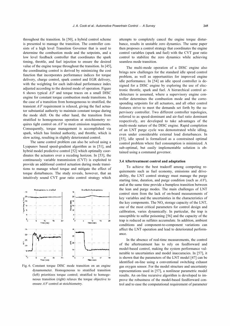
storage, a dynamic optimal control problem has to be for-mulated, because fuel consumption and emissions, evalu-ated over a specified driving cycle, are not simply functions of the instantaneous speed-load point, but of the operating history of the engine. The high degree of freedom intro-duced by the multiplicity of the control variables, coupled with time and trajectory dependency, leads to a very high dimension optimization problem. In [59] a method is in-troduced that dramatically reduces the computational bur-den of dynamic programming to make model-based design decisions for the lean-burn DISC powertrain. Results showing the sensitivity of the fuel economy performance objective at European Stage IV emission standards with respect to physical aftertreatment parameters, including the amount of oxygen storage in the TWC and the capacity of the lean NOx trap, are presented. In another trade-off study, control complexity is evaluated with respect to emissions benefit. Specifically, the optimal fuel economy, constrained by Stage III and Stage IV requirements, is evaluated to show the potential effects of eliminating the homogeneous lean combustion mode. It is determined, as illustrated in Fig. 7 of [46], that as NOx emission requirements become more stringent, the benefits of operating the engine in the homogeneous lean mode become less appreciable, up to a point where the incremental benefits may not be enough to justify the additional complexity.
The most important contributions of [59] are meth-odological. In particular, the computationally intense dy-namic programming algorithm is rendered tractable by model simplification, state descretization, and analy-sis-based restriction on the search trajectories (called “cali-brations”) along with careful treatment of computational details. The dynamic programming problem for a two-state system (TWC plus LNT) over an emissions drive-cycle was reduced to 40 minutes from 60 hours, while still
achieving a near-optimal solution as shown in Fig. 7. These results are similar to the system optimization prob-lems of hybrid vehicles, which will be discussed in more detail in Section 5. Stochastic dynamic programming and game-theoretic methods are explored for this purpose in [60,61].
Using dynamic programming, the authors of [62] also explore the benefits of air-fuel ratio profiling in achieving improved fuel economy, NOx and HC emissions tradeoffs. By allowing A/F to vary during the purge phase, they show that substantial leverage can be achieved in reducing HC and NOx emissions, without a negative impact on fuel economy.
IV. CONTROL OF AUTOMOTIVE DIESEL ENGINES
Diesel engines offer superior fuel economy compared to their conventional gasoline counterparts. Their draw-backs are associated with higher cost, and complexity of the aftertreatment system. Despite an earlier skepticism by even some of their developers,2 diesel engines have achieved a remarkable passenger car market penetration in Europe thanks to technology improvements. The consensus is that their penetration in North America will grow too, albeit at a slower pace due to differences in fuel cost and taxation.
Fig. 7. Fuel economy versus NOx emissions of optimal pol-
icy with calibrations and full optimization over the Euro-cycle. The DISI engine and aftertreatment mod-els are quasi-static. The LNT NOx filling and empty-ing is dynamically updated.
2 Sir Harry Ricardo stated in 1925 that “...the exhaust from diesel engines ... has a characteristic pungent and disagreeable smell... the author cannot believe that the police will allow any large proportion of diesel-engined vehicles in the streets of, say, London.”
J. A. Cook et al.: Automotive Powertrain Control ⎯ A Survey 247
Diesel engines are typically turbocharged or super-charged to improve power density. A variable geometry turbocharger (VGT) enables optimal “sizing” of the turbine for each engine operating condition by opening or closing inlet guide vanes [63], resulting in both improved fuel economy and engine responsiveness. Electric boosting assist devices [64] have been developed for this purpose as well.
Diesel engines, operated on the compression ignition principle, have many different features compared to spark ignited gasoline engines. In particular, the following char-acteristics of diesel engines have strong control implica-tions. First, they operate lean (A/F must usually stay above 22), and therefore require a different aftertreatment system. Second, NOx control, to a much greater extent compared to conventional gasoline engines, relies on high EGR which, due to the lean operation, can contain significant amounts of combustible air. Third, the fueling rate is an independent and fast actuator for torque management, as long as the A/F is maintained within its limits. Modern common rail fuel injection systems permit fuel rate shaping and multiple injections per cycle for torque, noise and emission controls.
4.1 Diesel engine models Mean value models and cylinder-by-cylinder diesel
engine models have been utilized for control system design and validation. Mean value modeling of diesel engines has been covered in the review articles [65,66] and in the book [6], while the cylinder-by-cylinder modeling is addressed in [66] and [67]. Different approaches to control oriented turbocharger modeling, including variable geometry tur-bochargers, are reviewed in the article [37]. References [68-70] explore the use of neural networks and related nonlinear identification techniques for diesel engine mod-eling.
A mean value model is developed in [71] for a diesel engine equipped with a VGT and an EGR valve. Compared to naturally aspirated gasoline engine models, diesel engine mean value models tend to be higher order. They capture the composition and temperature dynamics in the intake and exhaust manifolds and the turbocharger dynamics in addition to the manifold pressure dynamics. The engine torque is modeled as a static function of these states and inputs.
Cylinder-by-cylinder models predict cylinder pressure and engine torque with crank angle resolution. They use mass and energy balances to model the in-cylinder gas properties, in addition to manifold and turbocharger dy-namics. In the simplest kinds of these models, the mass fraction of fuel burned is modeled as a function of the crank angle using Wiebe functions and the cylinder heat transfer is modeled using Hohenberg correlations. The in-take and exhaust valve gas flows are modeled based on the orifice equations while the gas thermodynamic properties are captured using the Krieger-Borman relations. Reference
[72] describes the use of a novel quadratic exponential fit for the mass of fuel burned and contains further references on the subject of cylinder-by-cylinder modeling. It also illustrates the use of a cylinder-by-cylinder model for a cylinder balancing application.
4.2 Control problems for diesel engines Diesel engines provide many challenging control
problems. The number of inputs (degrees of freedom) which needs to be dynamically controlled in a diesel engine ranges between 8 and 20, depending on the engine con-figuration. It can be even higher if individual cylinder be-havior is taken into account. An increase in modeling, con-trol and calibration complexity occurs with each added degree of freedom. Diesel engine dynamics are not only highly nonlinear but they are higher order than the ones for non-boosted gasoline engines. Static and dynamic interac-tions inherent to high order multi-input multi-output nonlinear systems complicate the control system develop-ment. Some of the control problems and pertinent solutions are briefly discussed here. The review articles [65,73] and the book [74] also cover many of the aspects and literature on diesel engine control.
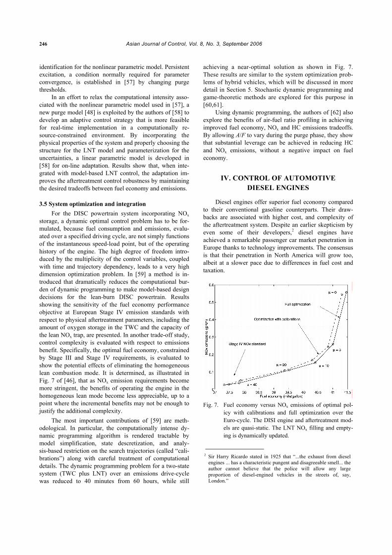
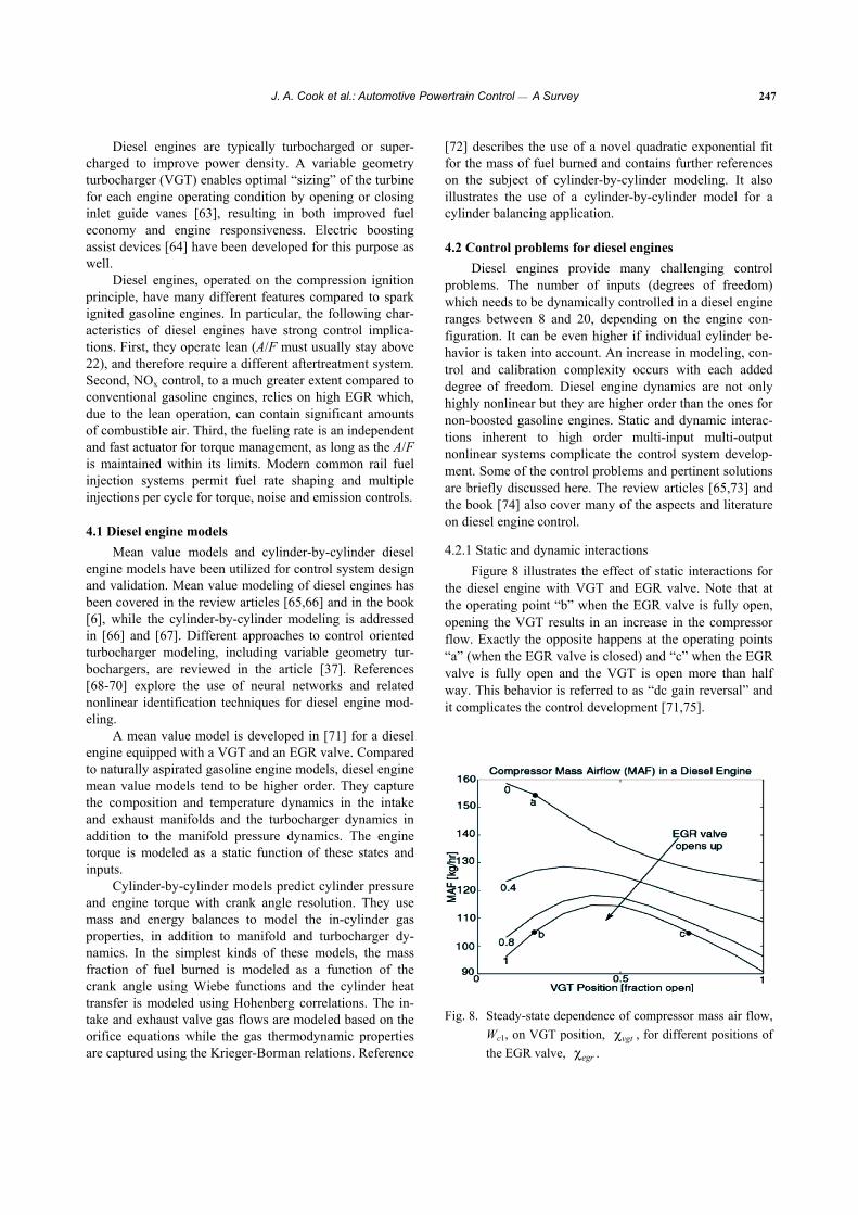
4.2.1 Static and dynamic interactions Figure 8 illustrates the effect of static interactions for
the diesel engine with VGT and EGR valve. Note that at the operating point “b” when the EGR valve is fully open, opening the VGT results in an increase in the compressor flow. Exactly the opposite happens at the operating points “a” (when the EGR valve is closed) and “c” when the EGR valve is fully open and the VGT is open more than half way. This behavior is referred to as “dc gain reversal” and it complicates the control development [71,75].
Fig. 8. Steady-state dependence of compressor mass air flow, Wc1, on VGT position, vgtχ , for different positions of the EGR valve, .egrχ
248 Asian Journal of Control, Vol. 8, No. 3, September 2006
The dynamic phenomena important for control design have been illustrated in [71] where it is shown that the en-gine dynamics become slower when the EGR valve is more open, and that for the usual selection of outputs the system may exhibit non-minimum phase behavior. It is also shown through numerical optimal control-based analysis [75] that the optimal operating strategy of the VGT during a tip-in may not be its immediate closing (as the purely steady-state analysis would suggest). If the VGT is closed immediately during the tip-in, the exhaust pressure may increase rapidly in advance of the pressure increase in the intake manifold, thereby reducing the volumetric efficiency, increasing pumping losses, and increasing the turbo-lag. A more op-timal operation of the VGT during this transient is to ini-tially open it, then close it and reopen it again at higher rpm to prevent over-boost.
4.2.2 Selection of sensor configuration and control system architecture
In view of static and dynamic interactions in the diesel engine, the proper selection of sensor configuration and control system architecture is particularly important. Dif-ferent internal variables may be used for feedback and they result in different levels of sensitivity to uncertainties and transient performance.
The simplest analysis procedure is to determine the steady-state sensitivities of key performance variables (such as fuel consumption and emissions) to the uncertain-ties for different sensor and controller configurations. The underlying assumption in this analysis is that a measured internal variable is maintained by the controller at the de-sired setpoint despite the effects of the uncertainties. In order for this analysis to lead to meaningful conclusions, the relative importance of performance variables and the expected size of uncertainties need to be established. Note also that the best sensor configuration or controller archi-tecture may, in general, depend on the engine operating point, as was noted previously for DISC gasoline engines.
Other related procedures include the use of con-trol-theoretic techniques such as Relative Gain Array (RGA) analysis [71] and µ-analysis [76]. The value of µ is computed in [76] for different sensor configurations and at different operating points wherein low µ implied high ro-bustness against uncertainties and small tracking errors. It is shown that although the numerical value of µ changes with the operating point, the relative ranking of the differ-ent configurations remains the same, thus permitting the identification of the best sensor configuration across the full engine operating range.
Besides formal procedures that consider the effect of uncertainties, the direct analysis of interactions and proper-ties of the system may lead to an effective control archi-tecture. In [34], the feedback architecture is designed based on consideration of available actuator authority at the op-timal setpoints. It is shown that locally at these optimal setpoints, the EGR valve and the VGT become limited in
their ability to independently affect the performance vari-ables. This analysis led to a feedback controller architec-ture reliant on a single integrator instead of two. In refer-ence [35], the exhaust pressure measurement is introduced to avoid the nonminimum-phase dynamics associated with the standard sensor configuration (compressor mass air flow and intake manifold pressure) and take advantage of the relative degree properties of the re-defined output set. This enabled application of effective robust nonlinear con-trol design techniques. References [78,79] propose com-bining switching logic and PID controllers to provide fast boost pressure response with small overshoot. Reference [80] utilizes an air-fuel ratio sensor positioned after the turbine and an LQG/LTR controller for the EGR valve in an engine with a conventional turbocharger. The use of the air-fuel ratio sensor can improve the system robustness and reduce calibration effort, although the transient perform-ance may be limited due to the delay and sensor dynamics.
The guidelines resulting from numerical optimal con-trol [75] can also be useful in comparing different control-ler architectures with each other in terms of their capability to generate an optimal behavior and for ease of subsequent controller calibration. For example, it is shown in [75] that the conventional decentralized architecture, wherein the VGT is controlled using a proportional plus integral feed-back on intake manifold pressure and the EGR valve is controlled using a proportional plus integral feedback on the compressor mass air flow, is limited in its ability to generate the optimal behavior.
4.2.3 Coordinated EGR-VGT control Coordinated control of the EGR valve and VGT has
been a very active and recent research topic, with extensive literature on both linear and nonlinear control design ap-proaches. Reference [81] compares several different linear and nonlinear control designs.
One of the controllers featured in [81] is a multivari-able linear proportional-plus-integral (MIMO PI) controller for EGR valve and VGT position which uses the measure-ments of the intake manifold pressure and compressor mass air flow for feedback. This controller uses a decoupling transformation based on an inverse of the (static) dc gain of the plant for different operating conditions. Only 4 master gains need to be tuned on the engine while the decoupling transformation provides a mechanism for automatic gain scheduling.
Reference [35] develops a nonlinear controller for the diesel engine based on the method of Control Lyapunov Functions applied to a reduced order model of the diesel engine. The Control Lyapunov Function (CLF) is con-structed as a Lyapunov function for the closed-loop system with a feedback linearizing controller; the CLF controller is then derived from the Lyapunov function for the desired mass flow rate of EGR and desired mass flow rate through the turbine. The EGR valve and turbine flow characteristics are inverted to backtrack the desired EGR valve and VGT
J. A. Cook et al.: Automotive Powertrain Control ⎯ A Survey 249
positions from the desired flow rates. The CLF controller enjoys input uncertainty robustness properties such as infi-nite gain margin and 60 degree phase margin and high-lights the advantages of using the exhaust manifold pres-sure measurement for feedback [35]. Reference [77] ex-tends the CLF-based controller to a diesel engine model with delay using the method of Lyapunov-Krasovsky func-tionals.
Authors of [82] propose to control the EGR valve us-ing feedback on the error between estimated and requested cylinder fresh air flow while the controller for VGT is de-rived using feedback passivation ideas to enforce specified exhaust pressure dynamics. In addition, on-line parameter identification is employed to learn parameters in the cylin-der flow and turbocharger models. Feedback passivation design using a master/slave approach is developed in [83]. A sliding mode controller is designed in [84] for the VGT and later extended to both EGR valve and VGT in [85]. A set of linear feedback controllers is designed in [86] and a switching logic is developed to control the engine response by selecting controllers in a sequence from this set. The design of each of the controllers in [86] relies on a poly-topic representation of the model and the application of linear matrix inequality techniques. Reference [87] devel-ops and implements a Model Predictive Control (MPC) algorithm for the coordinated control of EGR valve and VGT. It shows that the parameters in the cost function can be effectively used to shape the system transient response and demonstrates that the performance of the conventional controller has been either matched or exceeded. Bai and Yang [88] illustrate the benefits of a control algorithm which uses an estimate of cylinder air flow for feedback. Interactions between fueling and VGT is considered in [89]. It applies an inverse Nyquist array technique to analyze the interactions and design a controller for the system.
4.2.4 Composition estimation and fuel limiting To avoid visible smoke emissions and reduce
turbo-lag, a precise estimate of fresh air charge inducted into the engine cylinders is needed. The fueling rate can then be limited according to the fresh air charge estimate to maintain A/F above the smoke limit. The estimation of fresh air charge is complicated because the flow through the EGR valve and the gas mixture in both intake and ex-haust manifolds contains both burned gas and fresh air.
Inasmuch as estimating the burned gas fraction is concerned, it is essentially unobservable from standard pressure and flow measurements in the diesel engine [71]. Therefore, an open-loop observer based on the burned gas fraction dynamic model [90], in combination with input observers [91], is used.
Charge estimation problems for diesel engines are studied in a number of other references. They include [92] which derives an adaptive observer for the cylinder flow in the diesel engine without EGR and demonstrates improve-ments over the conventional (open-loop) approach.
Andersson and Eriksson [93] consider a related problem of the observer design for cylinder flow estimation in a diesel engine with a conventional wastegated turbocharger and without external EGR.
4.2.5 Aftertreatment control Tailpipe NOx and particulate emissions (PM) represent
particular challenges for diesel engines, because lean op-eration renders the conventional three-way catalyst ineffec-tive. Much of present controls research is focused on the control of aftertreatment systems such as active lean NOx catalysts (ALNC), lean NOx traps (LNT), urea selective catalytic reduction (SCR), plasma catalysts and diesel par-ticulate filters (DPF).
In an aftertreatment system with ALNC, engine fuel (i.e., HC) is injected upstream of the catalyst (typically by a special injector) to provide a reducing agent for the oxides of nitrogen in the ALNC. The control system must deter-mine the quantity of the HC and control the temperature in order to maximize the ALNC conversion efficiency. The complicating factors are the hydrocarbon storage phe-nomenon in the catalyst and the interactions between hy-drocarbon storage and temperature. A control oriented model for the ALNC is developed and extended in [94,95]. Dynamic programming is applied in [94] to generate a con-trol law that minimizes the weighted sum of tailpipe NOx and spent fuel.
An LNT like that used in lean-burn gasoline applica-tions can also be considered for diesel engine NOx control. This application, however, is particularly arduous as it has the same challenges faced by the lean-burn gasoline engine, in addition to the demands associated with the low operat-ing temperatures of the diesel engine [95]. LNT tempera-ture can be controlled with engine-based methods or by external methods, such as flow control devices in the ex-haust and/or an oxidation catalyst placed upstream of the LNT. Each approach presents its own control challenges. Engine-based control has limited authority given compet-ing objectives of fuel economy, performance and engine out emissions. Exhaust flow control devices involve addi-tional hardware, including control valves, which increase cost and complexity, and introduce durability issues. An oxidation catalyst works well in a lean environment, but the duration of rich A/F conditions must be fairly short to avoid loss of authority.
A potential alternative to the LNT is SCR technology, where urea is injected upstream of a selective reduction catalyst [96]. Urea decomposes to ammonia, which serves as the reductant in the conversion of NOx. Accurate control of urea injection is critical for conversion efficiency and to avoid breakthrough of ammonia, which can lead to a foul odor at the tailpipe. The control problem is complicated by the transient nature of automotive applications. A control oriented model is developed in [97]. Observer based feed-forward control is implemented in [98], along with feed-back from a NOx sensor. NOx measurement issues, includ-ing sensor sensitivity to ammonia, are discussed.
250 Asian Journal of Control, Vol. 8, No. 3, September 2006
A DPF collects particulates emitted by the diesel en-gine. As particulates accumulate, backpressure increases, resulting in deteriorated fuel economy. To avoid the fuel economy loss, the DPF must be periodically regenerated by increasing its inlet temperature to a sufficiently high level to burn the stored particulates. Oxygen flow to the DPF must be carefully controlled during regeneration to avoid an over-temperature condition and damage to the DPF. The temperature increase can be achieved by fuel post-injection (i.e., injecting an extra amount of fuel late in the expansion stroke) and by coordinated control of the EGR valve, VGT and throttle to reduce the air flow through the engine. If an oxidation catalyst is available upstream of the DPF, inject-ing HC ahead of the catalyst creates an exothermic reaction which helps to increase DPF temperature. The key control problems for the DPF are estimating the soot level in the DPF (typically, from the measured pressure difference across the DPF), optimally deciding at which soot level to start regeneration, and controlling regeneration without affecting vehicle drivability and fuel economy or violating temperature limits for the DPF and oxidation catalyst. Ref-erences [99] and [100] provide more background on the associated control problems.
V. ELECTRIC HYBRID POWERTRAIN SYSTEMS
Hybrid vehicles, especially hybrid electric vehicles (HEV), have demonstrated significant potential in reducing fuel consumption and exhaust emissions while maintaining driving performance. Hybrid powertrains may be viewed as a technology competing with variable valve timing, diesel, variable displacement and other fuel saving techniques. A natural question then arises: when would it make sense to choose a hybrid powertrain as opposed to other techniques (several of which are discussed in this paper)? Many “sys-tem-level” simulation studies have been conducted to compare the cost benefits of these techniques; see [101,102]. However, these system-level analyses are highly dependent on the underlying assumptions, such as fuel cost, and may not be that useful for predicting the future benefits and cost of ownership. Therefore, we will focus on a dis-cussion of the fundamental performance benefits of hybrid electric powertrains.
By reviewing the design philosophy and functionality of existing HEVs, it is apparent that HEVs offer a few unique attributes in comparison to other engine-centric fuel saving techniques: (i) regenerating braking—energy that would otherwise be lost—which is only possible because a reversible secondary power source is present; (ii) compo-nent down-sizing or right-sizing—which is possible only when a competent secondary power source is present in parallel; and (iii) the fuel economy improvement (up to 100%) that has been demonstrated for hybrid vehicles. This improvement is available partly because of the first two attributes, and partly because of the control algorithm that properly coordinates the operation of the multiple power sources.
Due to the fact that a hybrid powertrain provides sig-nificantly increased flexibility, it is possible to size the components and integrate them together to achieve vastly different design targets. For example, for smaller passenger cars, which are more likely to be driven in an urban envi-ronment, fuel economy can be given the highest priority. For SUVs, on the other hand, improved launch perform-ance (0~60 time) can be a decisive issue for a purchaser. For luxury sedans, the possibility of greatly improved NVH (noise-vibration-harshness) may be more important than the other potential benefits.
When fuel economy is the main design goal, as a gen-eral rule of thumb, a driving environment with lower aver-age speed and frequent acceleration/deceleration is likely to see higher improvement. Larger vehicles (e.g., a large SUV) will probably see larger and faster market penetra-tion, compared with smaller vehicles, because of their more favorable fuel saving returns.
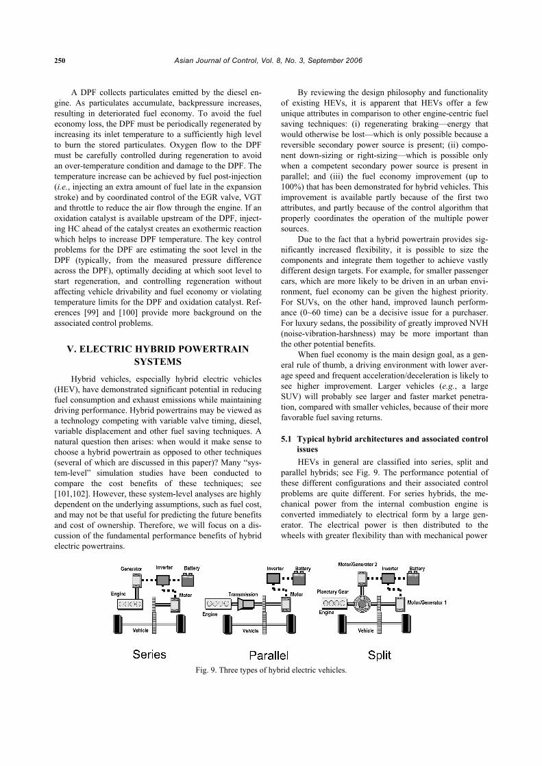
5.1 Typical hybrid architectures and associated control issues HEVs in general are classified into series, split and
parallel hybrids; see Fig. 9. The performance potential of these different configurations and their associated control problems are quite different. For series hybrids, the me-chanical power from the internal combustion engine is converted immediately to electrical form by a large gen-erator. The electrical power is then distributed to the wheels with greater flexibility than with mechanical power
Fig. 9. Three types of hybrid electric vehicles.
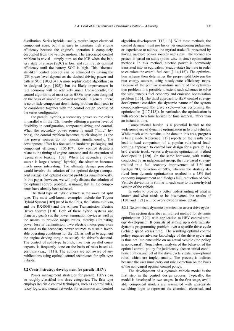
J. A. Cook et al.: Automotive Powertrain Control ⎯ A Survey 251
distribution. Series hybrids usually require larger electrical component sizes, but it is easy to maintain high engine efficiency because the engine’s operation is completely decoupled from the vehicle motion. The associated control problem is trivial—simply turn on the ICE when the bat-tery state of charge (SOC) is low, and run it at its optimal efficiency until the battery SOC is high. This “thermo-stat-like” control concept can be enhanced by having the ICE power level depend on the desired driving power and battery SOC [103,104]. A more sophisticated algorithm can be designed (e.g., [105]), but the likely improvement in fuel economy will be relatively small. Consequently, the control algorithms of most series HEVs have been designed on the basis of simple rule-based methods. In general, there is no or little component down-sizing problem that needs to be considered together with the control design because of the series configuration.
For parallel hybrids, a secondary power source exists in parallel with the ICE, thereby offering a greater level of flexibility in configuration, component sizing, and control. When the secondary power source is small (“mild” hy-brids), the control problem becomes much simpler, as the two power sources do not operate simultaneously. The development effort has focused on hardware packaging and component efficiency [106,107]. Key control decisions relate to the timing of engine start/stop and the execution of regenerative braking [108]. When the secondary power source is large (“strong” hybrids), the situation becomes much more interesting. The ultimate design procedure would involve the solution of the optimal design (compo-nent sizing) and optimal control problems simultaneously. In this paper, however, we will only discuss the solution of the optimal control problem, assuming that all the compo-nents have already been selected.
The third type of hybrid vehicle is the so-called split type. The most well-known examples include the Toyota Hybrid System [109] (used in the Prius, the Estima minivan, and the RX400H) and the Allison Transmission Electric Drives System [110]. Both of these hybrid systems use planetary gear(s) as the power summation device as well as the means to provide torque ratios, thereby eliminating power loss in transmission. Two electric motor/generators are used as the secondary power sources to sustain favor-able operating conditions for the ICE as well as to augment the engine driving torque to satisfy the driver’s demand. The control of split-type hybrids, like their parallel coun-terparts, is frequently done on the basis of rules-based al-gorithms (e.g., [111]). The authors are not aware of any publications using optimal control techniques for split-type hybrids.
5.2 Control strategy development for parallel HEVs Power management strategies for parallel HEVs can
be roughly classified into three categories. The first type employs heuristic control techniques, such as control rules, fuzzy logic, and neural networks, for estimation and control
algorithm development [112,113]. With these methods, the control designer must use his or her engineering judgement or experience to address the myriad tradeoffs presented by having multiple power sources and sinks. The second ap-proach is based on static (point-wise-in-time) optimization methods. In this method, electric power is commonly translated into an equivalent (steady-state) fuel rate in order to calculate the overall fuel cost ([114,115]). The optimiza-tion scheme then determines the proper split between the two energy sources using steady-state efficiency maps. Because of the point-wise-in-time nature of the optimiza-tion problem, it is possible to extend such schemes to solve the simultaneous fuel economy and emission optimization problem [116]. The third approach to HEV control strategy development considers the dynamic nature of the system components—and the drive cycle—when performing the optimization ([117,118]). In particular, the optimization is with respect to a time horizon or time interval, rather than an instant in time.
Computational burden is a potential barrier to the widespread use of dynamic optimization in hybrid vehicles. While much work remains to be done in this area, progress is being made. Reference [119] reports on the results of a head-to-head comparison of a popular rule-based load- leveling approach to control law design for a parallel hy-brid electric truck, versus a dynamic optimization method developed in [120]. On the same hardware, with testing conducted by an independent group, the rule-based strategy resulted in a fuel economy improvement of 31% and feedgas NOx reduction of 50%, whereas the strategy de-rived from dynamic optimization resulted in a 45% fuel economy improvement and feedgas NOx reduction of 54%. Vehicle drivability is similar in each case to the non-hybrid version of the vehicle.
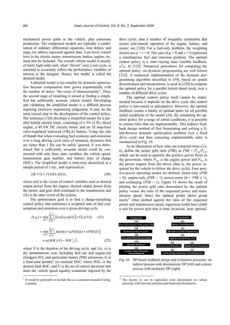
In order to provide a better understanding of what is known and what needs to be discovered, the results of [120] and [121] will be overviewed in more detail.
5.2.1 Deterministic dynamic optimization over a drive cycle This section describes an indirect method for dynamic
optimization [120], with application to HEV control strat-egy development. It consists of setting up a deterministic dynamic programming problem over a specific drive cycle (vehicle speed versus time). The resulting optimal control policy requires advance knowledge of the drive cycle and is thus not implementable on an actual vehicle (the policy is non-causal). Nonetheless, analysis of the behavior of the optimal control policy for judiciously chosen initial condi-tions both on and off of the drive cycle yields near-optimal rules, which are implementable. The process is indirect because the user must carry out rule extraction on the basis of the non-causal optimal control policy.
The development of a dynamic vehicle model is the first step in the control design process. Typically, the model is developed in two stages. In the first stage, avail-able component models are assembled with appropriate switching logic to represent the chemical, electrical, and
252 Asian Journal of Control, Vol. 8, No. 3, September 2006
mechanical power paths in the vehicle, plus emissions production. The component models are typically a combi-nation of ordinary differential equations, time delays, and maps (or tables) regressed against data. Low-level control laws in the electric motor, transmission, brakes, engine, etc. must also be included. The overall vehicle model is usually of fairly high order and, when “driven” over a test cycle, is assumed to accurately reflect the performance variables of interest to the designer. Hence, this model is called the detailed model.
A detailed model is not suitable for dynamic optimiza-tion because computation time grows exponentially with the number of states: “the curse of dimensionality”. Thus, the second stage of modeling is aimed at finding a simpli-fied but sufficiently accurate vehicle model. Developing and validating the simplified model is a difficult process requiring extensive engineering judgement. It may be the most crucial step in the development of the control policy. The reference [120] develops a simplified model for a par-allel hybrid electric truck, consisting of a V6 (5.5L) diesel engine, a 49 kW DC electric motor, and an 18 amp-hour valve-regulated lead-acid (VRLA) battery. Using the rule of thumb that when evaluating fuel economy and emissions over a long driving cycle (tens of minutes), dynamics that are faster than 1 Hz can be safely ignored, it was deter-mined that a sufficiently accurate model could be con-structed with only three state variables: the vehicle speed, transmission gear number, and battery state of charge (SOC). The simplified model is time-wise discretized at a sample period of 1 sec., and expressed as:
( 1) ( ( ) ( ))x k f x k u k+ = , , (20)
where u(k) is the vector of control variables such as desired output power from the engine, desired output power from the motor, and gear shift command to the transmission and x(k) is the state vector of the system.
The optimization goal is to find a charge-sustaining control policy that minimizes a weighted sum of fuel con-sumption and emissions over a given driving cycle
1
00
( ) min ( ( ) ( )) ( ( ))N
u U kJ x L x k u k G x N
−
∈ == , +⎡ ⎤⎣ ⎦∑ (21)
1
0min ( ) ( ) ( )
N
u U kfuel k NOx k PM k
−
∈ == + µ + ν⎡ ⎤⎣ ⎦∑
2( ( ) )fSOC N SOC+ α − , (22)
where N is the duration of the driving cycle, and L(x, u) is the instantaneous cost, including fuel use and engine-out (feedgas) NOx and particulate matter (PM) emissions; G is a final-state penalty3 on terminal SOC, where SOCf is the desired final SOC; and U is the set of control decisions that meet the vehicle speed equality constraint imposed by the
drive cycle, plus a number of inequality constraints that ensure safe/smooth operation of the engine, battery, and motor; see [120]. For a fuel-only problem, the weighting factors are µ = v = 0. The case of µ > 0 and v > 0 represents a simultaneous fuel and emission problem. The optimal control policy is a time-varying state variable feedback, u*(x, k) [122]. Numerical procedures for computing the optimal policy via dynamic programming are well known [122]. A numerical implementation of the dynamic pro-gramming algorithm described in [59], based on spatial discretization and interpolation, is used in [120] to compute the optimal policy for a parallel hybrid diesel truck, over a number of different drive cycles.
The optimal control policy itself cannot be imple-mented because it depends on the drive cycle (the control policy is non-causal or anticipative). However, the optimal feedback creates a family of optimal paths for all possible initial conditions of the model (20). By simulating the op-timal policy for a range of initial conditions, it is possible to extract rules that are implementable. This indirect feed-back design method of first formulating and solving a fi-nite-horizon dynamic optimization problem over a fixed drive cycle and then extracting implementable rules is summarized in Fig. 10.
As an illustration of how rules are extracted from u*(x, k), define the power split ratio (PSR) as PSR = Peng/Preq, which can be used to quantify the positive power flows in the powertrain, where Peng is the engine power and Preq is the power request from the driver (that is, the power re-quired for the vehicle to follow the drive cycle). Four posi-tive-power operating modes are defined: motor-only (PSR = 0), engine-only (PSR = 1), power-assist (0 < PSR ≤ 1), and recharging (PSR > 1). Figure 11 shows the result of plotting the power split ratio determined by the optimal policy versus the ratio of the requested power and trans-mission speed. Since the optimal points (dots) group nicely4 when plotted against the ratio of the requested power and transmission speed, regression (solid line) yields a rule for power split that is time invariant, near optimal,
Fig. 10. DP-based feedback design and evaluation processes: an
indirect process with deterministic DP (left) and a direct process with stochastic DP (right).
3 It would be preferable to include this as a constraint instead of using a penalty.
4 The factors to use in regression were determined via subset selection, with forward selection and backward elimination.
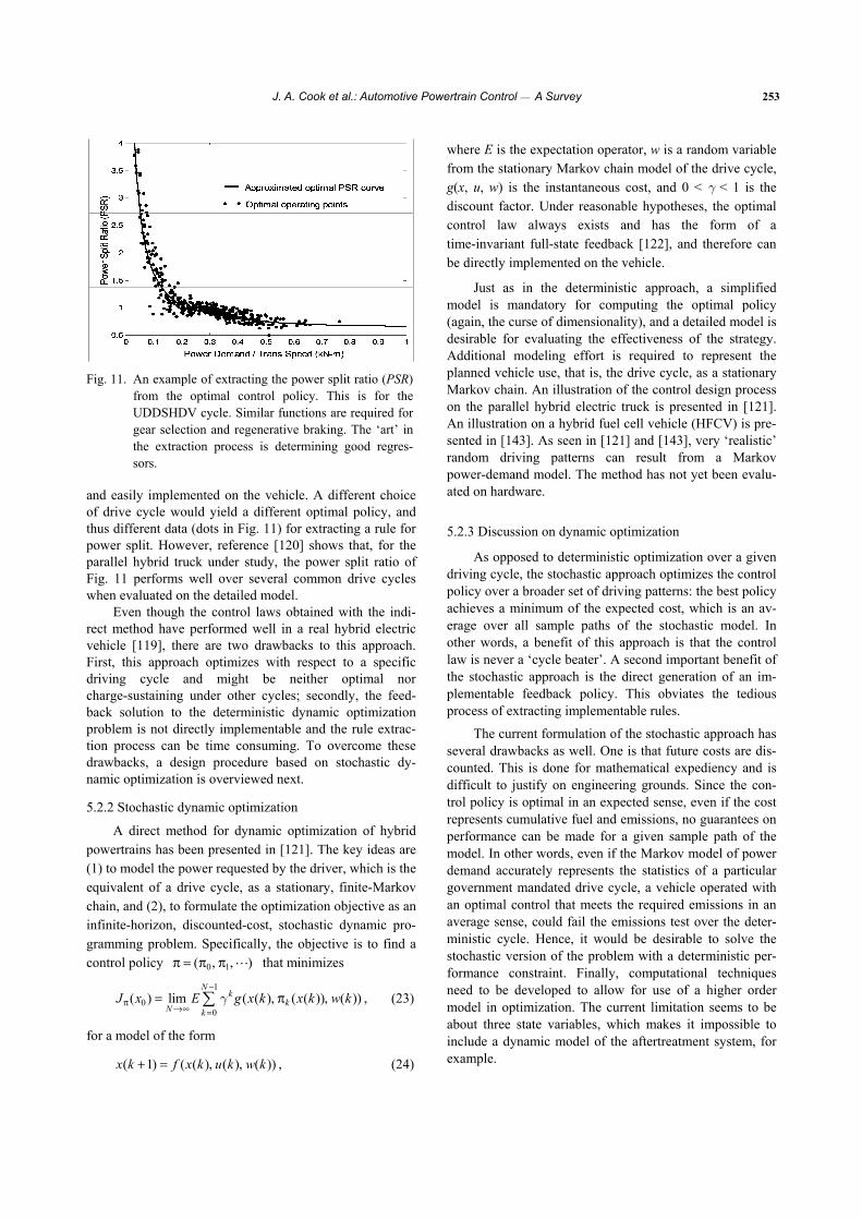
J. A. Cook et al.: Automotive Powertrain Control ⎯ A Survey 253
Fig. 11. An example of extracting the power split ratio (PSR)
from the optimal control policy. This is for the UDDSHDV cycle. Similar functions are required for gear selection and regenerative braking. The ‘art’ in the extraction process is determining good regres-sors.
and easily implemented on the vehicle. A different choice of drive cycle would yield a different optimal policy, and thus different data (dots in Fig. 11) for extracting a rule for power split. However, reference [120] shows that, for the parallel hybrid truck under study, the power split ratio of Fig. 11 performs well over several common drive cycles when evaluated on the detailed model.
Even though the control laws obtained with the indi-rect method have performed well in a real hybrid electric vehicle [119], there are two drawbacks to this approach. First, this approach optimizes with respect to a specific driving cycle and might be neither optimal nor charge-sustaining under other cycles; secondly, the feed-back solution to the deterministic dynamic optimization problem is not directly implementable and the rule extrac-tion process can be time consuming. To overcome these drawbacks, a design procedure based on stochastic dy-namic optimization is overviewed next.
5.2.2 Stochastic dynamic optimization
A direct method for dynamic optimization of hybrid powertrains has been presented in [121]. The key ideas are (1) to model the power requested by the driver, which is the equivalent of a drive cycle, as a stationary, finite-Markov chain, and (2), to formulate the optimization objective as an infinite-horizon, discounted-cost, stochastic dynamic pro-gramming problem. Specifically, the objective is to find a control policy 0 1( )π = π , π , that minimizes
1
00
( ) lim ( ( ) ( ( )) ( ))N
kk
N kJ x E g x k x k w k
−
π→∞ =
= , π , ,∑ γ (23)
for a model of the form
( 1) ( ( ) ( ) ( ))x k f x k u k w k+ = , , , (24)
where E is the expectation operator, w is a random variable from the stationary Markov chain model of the drive cycle, g(x, u, w) is the instantaneous cost, and 0 < γ < 1 is the discount factor. Under reasonable hypotheses, the optimal control law always exists and has the form of a time-invariant full-state feedback [122], and therefore can be directly implemented on the vehicle.
Just as in the deterministic approach, a simplified model is mandatory for computing the optimal policy (again, the curse of dimensionality), and a detailed model is desirable for evaluating the effectiveness of the strategy. Additional modeling effort is required to represent the planned vehicle use, that is, the drive cycle, as a stationary Markov chain. An illustration of the control design process on the parallel hybrid electric truck is presented in [121]. An illustration on a hybrid fuel cell vehicle (HFCV) is pre-sented in [143]. As seen in [121] and [143], very ‘realistic’ random driving patterns can result from a Markov power-demand model. The method has not yet been evalu-ated on hardware.
5.2.3 Discussion on dynamic optimization
As opposed to deterministic optimization over a given driving cycle, the stochastic approach optimizes the control policy over a broader set of driving patterns: the best policy achieves a minimum of the expected cost, which is an av-erage over all sample paths of the stochastic model. In other words, a benefit of this approach is that the control law is never a ‘cycle beater’. A second important benefit of the stochastic approach is the direct generation of an im-plementable feedback policy. This obviates the tedious process of extracting implementable rules.
The current formulation of the stochastic approach has several drawbacks as well. One is that future costs are dis-counted. This is done for mathematical expediency and is difficult to justify on engineering grounds. Since the con-trol policy is optimal in an expected sense, even if the cost represents cumulative fuel and emissions, no guarantees on performance can be made for a given sample path of the model. In other words, even if the Markov model of power demand accurately represents the statistics of a particular government mandated drive cycle, a vehicle operated with an optimal control that meets the required emissions in an average sense, could fail the emissions test over the deter-ministic cycle. Hence, it would be desirable to solve the stochastic version of the problem with a deterministic per-formance constraint. Finally, computational techniques need to be developed to allow for use of a higher order model in optimization. The current limitation seems to be about three state variables, which makes it impossible to include a dynamic model of the aftertreatment system, for example.
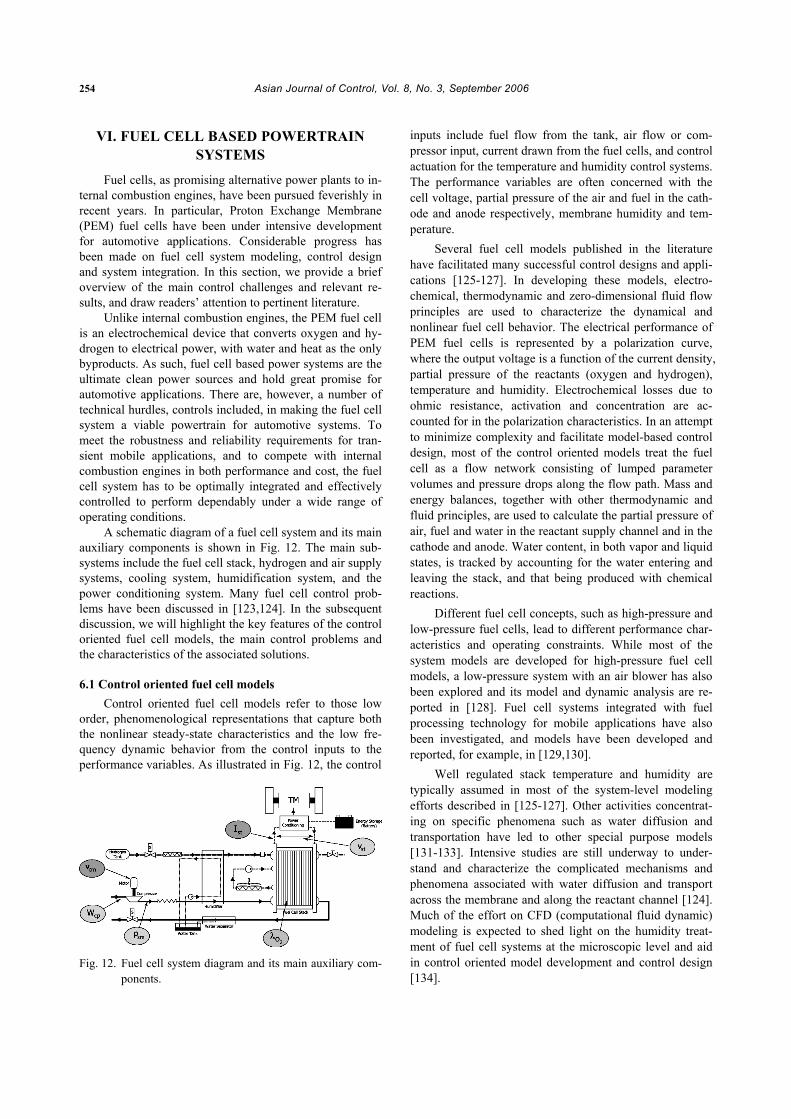
254 Asian Journal of Control, Vol. 8, No. 3, September 2006
VI. FUEL CELL BASED POWERTRAIN SYSTEMS
Fuel cells, as promising alternative power plants to in-ternal combustion engines, have been pursued feverishly in recent years. In particular, Proton Exchange Membrane (PEM) fuel cells have been under intensive development for automotive applications. Considerable progress has been made on fuel cell system modeling, control design and system integration. In this section, we provide a brief overview of the main control challenges and relevant re-sults, and draw readers’ attention to pertinent literature.
Unlike internal combustion engines, the PEM fuel cell is an electrochemical device that converts oxygen and hy-drogen to electrical power, with water and heat as the only byproducts. As such, fuel cell based power systems are the ultimate clean power sources and hold great promise for automotive applications. There are, however, a number of technical hurdles, controls included, in making the fuel cell system a viable powertrain for automotive systems. To meet the robustness and reliability requirements for tran-sient mobile applications, and to compete with internal combustion engines in both performance and cost, the fuel cell system has to be optimally integrated and effectively controlled to perform dependably under a wide range of operating conditions.
A schematic diagram of a fuel cell system and its main auxiliary components is shown in Fig. 12. The main sub-systems include the fuel cell stack, hydrogen and air supply systems, cooling system, humidification system, and the power conditioning system. Many fuel cell control prob-lems have been discussed in [123,124]. In the subsequent discussion, we will highlight the key features of the control oriented fuel cell models, the main control problems and the characteristics of the associated solutions.
6.1 Control oriented fuel cell models Control oriented fuel cell models refer to those low
order, phenomenological representations that capture both the nonlinear steady-state characteristics and the low fre-quency dynamic behavior from the control inputs to the performance variables. As illustrated in Fig. 12, the control
Fig. 12. Fuel cell system diagram and its main auxiliary com-
ponents.
inputs include fuel flow from the tank, air flow or com-pressor input, current drawn from the fuel cells, and control actuation for the temperature and humidity control systems. The performance variables are often concerned with the cell voltage, partial pressure of the air and fuel in the cath-ode and anode respectively, membrane humidity and tem-perature.
Several fuel cell models published in the literature have facilitated many successful control designs and appli-cations [125-127]. In developing these models, electro-chemical, thermodynamic and zero-dimensional fluid flow principles are used to characterize the dynamical and nonlinear fuel cell behavior. The electrical performance of PEM fuel cells is represented by a polarization curve, where the output voltage is a function of the current density, partial pressure of the reactants (oxygen and hydrogen), temperature and humidity. Electrochemical losses due to ohmic resistance, activation and concentration are ac-counted for in the polarization characteristics. In an attempt to minimize complexity and facilitate model-based control design, most of the control oriented models treat the fuel cell as a flow network consisting of lumped parameter volumes and pressure drops along the flow path. Mass and energy balances, together with other thermodynamic and fluid principles, are used to calculate the partial pressure of air, fuel and water in the reactant supply channel and in the cathode and anode. Water content, in both vapor and liquid states, is tracked by accounting for the water entering and leaving the stack, and that being produced with chemical reactions.
Different fuel cell concepts, such as high-pressure and low-pressure fuel cells, lead to different performance char-acteristics and operating constraints. While most of the system models are developed for high-pressure fuel cell models, a low-pressure system with an air blower has also been explored and its model and dynamic analysis are re-ported in [128]. Fuel cell systems integrated with fuel processing technology for mobile applications have also been investigated, and models have been developed and reported, for example, in [129,130].
Well regulated stack temperature and humidity are typically assumed in most of the system-level modeling efforts described in [125-127]. Other activities concentrat-ing on specific phenomena such as water diffusion and transportation have led to other special purpose models [131-133]. Intensive studies are still underway to under-stand and characterize the complicated mechanisms and phenomena associated with water diffusion and transport across the membrane and along the reactant channel [124]. Much of the effort on CFD (computational fluid dynamic) modeling is expected to shed light on the humidity treat-ment of fuel cell systems at the microscopic level and aid in control oriented model development and control design [134].
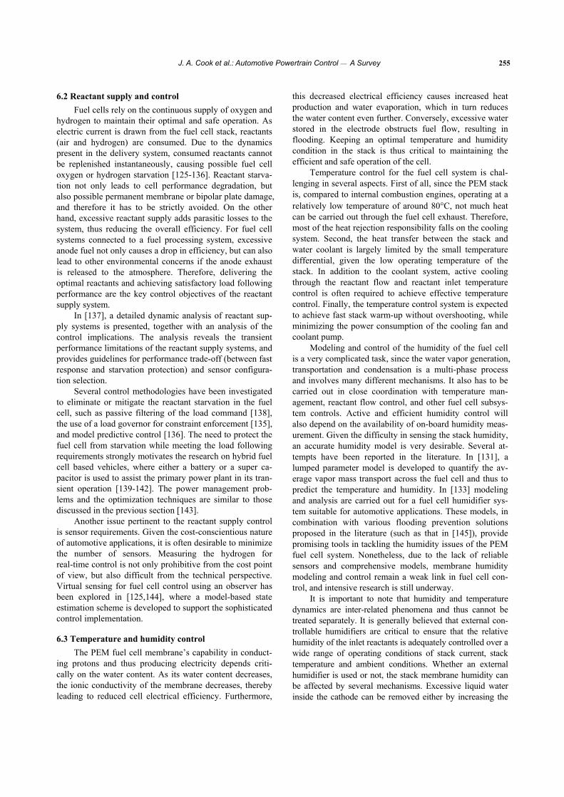
J. A. Cook et al.: Automotive Powertrain Control ⎯ A Survey 255
6.2 Reactant supply and control Fuel cells rely on the continuous supply of oxygen and
hydrogen to maintain their optimal and safe operation. As electric current is drawn from the fuel cell stack, reactants (air and hydrogen) are consumed. Due to the dynamics present in the delivery system, consumed reactants cannot be replenished instantaneously, causing possible fuel cell oxygen or hydrogen starvation [125-136]. Reactant starva-tion not only leads to cell performance degradation, but also possible permanent membrane or bipolar plate damage, and therefore it has to be strictly avoided. On the other hand, excessive reactant supply adds parasitic losses to the system, thus reducing the overall efficiency. For fuel cell systems connected to a fuel processing system, excessive anode fuel not only causes a drop in efficiency, but can also lead to other environmental concerns if the anode exhaust is released to the atmosphere. Therefore, delivering the optimal reactants and achieving satisfactory load following performance are the key control objectives of the reactant supply system.
In [137], a detailed dynamic analysis of reactant sup-ply systems is presented, together with an analysis of the control implications. The analysis reveals the transient performance limitations of the reactant supply systems, and provides guidelines for performance trade-off (between fast response and starvation protection) and sensor configura-tion selection.
Several control methodologies have been investigated to eliminate or mitigate the reactant starvation in the fuel cell, such as passive filtering of the load command [138], the use of a load governor for constraint enforcement [135], and model predictive control [136]. The need to protect the fuel cell from starvation while meeting the load following requirements strongly motivates the research on hybrid fuel cell based vehicles, where either a battery or a super ca-pacitor is used to assist the primary power plant in its tran-sient operation [139-142]. The power management prob-lems and the optimization techniques are similar to those discussed in the previous section [143].
Another issue pertinent to the reactant supply control is sensor requirements. Given the cost-conscientious nature of automotive applications, it is often desirable to minimize the number of sensors. Measuring the hydrogen for real-time control is not only prohibitive from the cost point of view, but also difficult from the technical perspective. Virtual sensing for fuel cell control using an observer has been explored in [125,144], where a model-based state estimation scheme is developed to support the sophisticated control implementation.
6.3 Temperature and humidity control The PEM fuel cell membrane’s capability in conduct-
ing protons and thus producing electricity depends criti-cally on the water content. As its water content decreases, the ionic conductivity of the membrane decreases, thereby leading to reduced cell electrical efficiency. Furthermore,
this decreased electrical efficiency causes increased heat production and water evaporation, which in turn reduces the water content even further. Conversely, excessive water stored in the electrode obstructs fuel flow, resulting in flooding. Keeping an optimal temperature and humidity condition in the stack is thus critical to maintaining the efficient and safe operation of the cell.
Temperature control for the fuel cell system is chal-lenging in several aspects. First of all, since the PEM stack is, compared to internal combustion engines, operating at a relatively low temperature of around 80°C, not much heat can be carried out through the fuel cell exhaust. Therefore, most of the heat rejection responsibility falls on the cooling system. Second, the heat transfer between the stack and water coolant is largely limited by the small temperature differential, given the low operating temperature of the stack. In addition to the coolant system, active cooling through the reactant flow and reactant inlet temperature control is often required to achieve effective temperature control. Finally, the temperature control system is expected to achieve fast stack warm-up without overshooting, while minimizing the power consumption of the cooling fan and coolant pump.
Modeling and control of the humidity of the fuel cell is a very complicated task, since the water vapor generation, transportation and condensation is a multi-phase process and involves many different mechanisms. It also has to be carried out in close coordination with temperature man-agement, reactant flow control, and other fuel cell subsys-tem controls. Active and efficient humidity control will also depend on the availability of on-board humidity meas-urement. Given the difficulty in sensing the stack humidity, an accurate humidity model is very desirable. Several at-tempts have been reported in the literature. In [131], a lumped parameter model is developed to quantify the av-erage vapor mass transport across the fuel cell and thus to predict the temperature and humidity. In [133] modeling and analysis are carried out for a fuel cell humidifier sys-tem suitable for automotive applications. These models, in combination with various flooding prevention solutions proposed in the literature (such as that in [145]), provide promising tools in tackling the humidity issues of the PEM fuel cell system. Nonetheless, due to the lack of reliable sensors and comprehensive models, membrane humidity modeling and control remain a weak link in fuel cell con-trol, and intensive research is still underway.
It is important to note that humidity and temperature dynamics are inter-related phenomena and thus cannot be treated separately. It is generally believed that external con-trollable humidifiers are critical to ensure that the relative humidity of the inlet reactants is adequately controlled over a wide range of operating conditions of stack current, stack temperature and ambient conditions. Whether an external humidifier is used or not, the stack membrane humidity can be affected by several mechanisms. Excessive liquid water inside the cathode can be removed either by increasing the
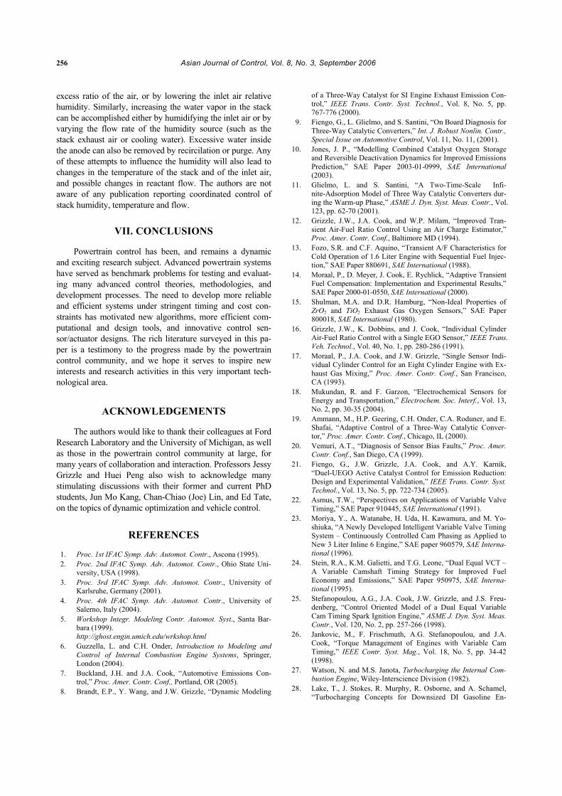
256 Asian Journal of Control, Vol. 8, No. 3, September 2006
excess ratio of the air, or by lowering the inlet air relative humidity. Similarly, increasing the water vapor in the stack can be accomplished either by humidifying the inlet air or by varying the flow rate of the humidity source (such as the stack exhaust air or cooling water). Excessive water inside the anode can also be removed by recircilation or purge. Any of these attempts to influence the humidity will also lead to changes in the temperature of the stack and of the inlet air, and possible changes in reactant flow. The authors are not aware of any publication reporting coordinated control of stack humidity, temperature and flow.
VII. CONCLUSIONS
Powertrain control has been, and remains a dynamic and exciting research subject. Advanced powertrain systems have served as benchmark problems for testing and evaluat-ing many advanced control theories, methodologies, and development processes. The need to develop more reliable and efficient systems under stringent timing and cost con-straints has motivated new algorithms, more efficient com-putational and design tools, and innovative control sen-sor/actuator designs. The rich literature surveyed in this pa-per is a testimony to the progress made by the powertrain control community, and we hope it serves to inspire new interests and research activities in this very important tech-nological area.
ACKNOWLEDGEMENTS
The authors would like to thank their colleagues at Ford Research Laboratory and the University of Michigan, as well as those in the powertrain control community at large, for many years of collaboration and interaction. Professors Jessy Grizzle and Huei Peng also wish to acknowledge many stimulating discussions with their former and current PhD students, Jun Mo Kang, Chan-Chiao (Joe) Lin, and Ed Tate, on the topics of dynamic optimization and vehicle control.
REFERENCES 1. Proc. 1st IFAC Symp. Adv. Automot. Contr., Ascona (1995). 2. Proc. 2nd IFAC Symp. Adv. Automot. Contr., Ohio State Uni-
versity, USA (1998). 3. Proc. 3rd IFAC Symp. Adv. Automot. Contr., University of
Karlsruhe, Germany (2001). 4. Proc. 4th IFAC Symp. Adv. Automot. Contr., University of
Salerno, Italy (2004). 5. Workshop Integr. Modeling Contr. Automot. Syst., Santa Bar-
bara (1999). http://ghost.engin.umich.edu/wrkshop.html
6. Guzzella, L. and C.H. Onder, Introduction to Modeling and Control of Internal Combustion Engine Systems, Springer, London (2004).
7. Buckland, J.H. and J.A. Cook, “Automotive Emissions Con-trol,” Proc. Amer. Contr. Conf., Portland, OR (2005).
8. Brandt, E.P., Y. Wang, and J.W. Grizzle, “Dynamic Modeling
of a Three-Way Catalyst for SI Engine Exhaust Emission Con-trol,” IEEE Trans. Contr. Syst. Technol., Vol. 8, No. 5, pp. 767-776 (2000).
9. Fiengo, G., L. Glielmo, and S. Santini, “On Board Diagnosis for Three-Way Catalytic Converters,” Int. J. Robust Nonlin. Contr., Special Issue on Automotive Control, Vol. 11, No. 11, (2001).
10. Jones, J. P., “Modelling Combined Catalyst Oxygen Storage and Reversible Deactivation Dynamics for Improved Emissions Prediction,” SAE Paper 2003-01-0999, SAE International (2003).
11. Glielmo, L. and S. Santini, “A Two-Time-Scale Infi-nite-Adsorption Model of Three Way Catalytic Converters dur-ing the Warm-up Phase,” ASME J. Dyn. Syst. Meas. Contr., Vol. 123, pp. 62-70 (2001).
12. Grizzle, J.W., J.A. Cook, and W.P. Milam, “Improved Tran-sient Air-Fuel Ratio Control Using an Air Charge Estimator,” Proc. Amer. Contr. Conf., Baltimore MD (1994).
13. Fozo, S.R. and C.F. Aquino, “Transient A/F Characteristics for Cold Operation of 1.6 Liter Engine with Sequential Fuel Injec-tion,” SAE Paper 880691, SAE International (1988).
14. Moraal, P., D. Meyer, J. Cook, E. Rychlick, “Adaptive Transient Fuel Compensation: Implementation and Experimental Results,” SAE Paper 2000-01-0550, SAE International (2000).
15. Shulman, M.A. and D.R. Hamburg, “Non-Ideal Properties of ZrO2 and TiO2 Exhaust Gas Oxygen Sensors,” SAE Paper 800018, SAE International (1980).
16. Grizzle, J.W., K. Dobbins, and J. Cook, “Individual Cylinder Air-Fuel Ratio Control with a Single EGO Sensor,” IEEE Trans. Veh. Technol., Vol. 40, No. 1, pp. 280-286 (1991).
17. Moraal, P., J.A. Cook, and J.W. Grizzle, “Single Sensor Indi-vidual Cylinder Control for an Eight Cylinder Engine with Ex-haust Gas Mixing,” Proc. Amer. Contr. Conf., San Francisco, CA (1993).
18. Mukundan, R. and F. Garzon, “Electrochemical Sensors for Energy and Transportation,” Electrochem. Soc. Interf., Vol. 13, No. 2, pp. 30-35 (2004).
19. Ammann, M., H.P. Geering, C.H. Onder, C.A. Roduner, and E. Shafai, “Adaptive Control of a Three-Way Catalytic Conver-tor,” Proc. Amer. Contr. Conf., Chicago, IL (2000).
20. Vemuri, A.T., “Diagnosis of Sensor Bias Faults,” Proc. Amer. Contr. Conf., San Diego, CA (1999).
21. Fiengo, G., J.W. Grizzle, J.A. Cook, and A.Y. Karnik, “Duel-UEGO Active Catalyst Control for Emission Reduction: Design and Experimental Validation,” IEEE Trans. Contr. Syst. Technol., Vol. 13, No. 5, pp. 722-734 (2005).
22. Asmus, T.W., “Perspectives on Applications of Variable Valve Timing,” SAE Paper 910445, SAE International (1991).
23. Moriya, Y., A. Watanabe, H. Uda, H. Kawamura, and M. Yo-shiuka, “A Newly Developed Intelligent Variable Valve Timing System – Continuously Controlled Cam Phasing as Applied to New 3 Liter Inline 6 Engine,” SAE paper 960579, SAE Interna-tional (1996).
24. Stein, R.A., K.M. Galietti, and T.G. Leone, “Dual Equal VCT – A Variable Camshaft Timing Strategy for Improved Fuel Economy and Emissions,” SAE Paper 950975, SAE Interna-tional (1995).
25. Stefanopoulou, A.G., J.A. Cook, J.W. Grizzle, and J.S. Freu-denberg, “Control Oriented Model of a Dual Equal Variable Cam Timing Spark Ignition Engine,” ASME J. Dyn. Syst. Meas. Contr., Vol. 120, No. 2, pp. 257-266 (1998).
26. Jankovic, M., F. Frischmuth, A.G. Stefanopoulou, and J.A. Cook, “Torque Management of Engines with Variable Cam Timing,” IEEE Contr. Syst. Mag., Vol. 18, No. 5, pp. 34-42 (1998).
27. Watson, N. and M.S. Janota, Turbocharging the Internal Com-bustion Engine, Wiley-Interscience Division (1982).
28. Lake, T., J. Stokes, R. Murphy, R. Osborne, and A. Schamel, “Turbocharging Concepts for Downsized DI Gasoline En-
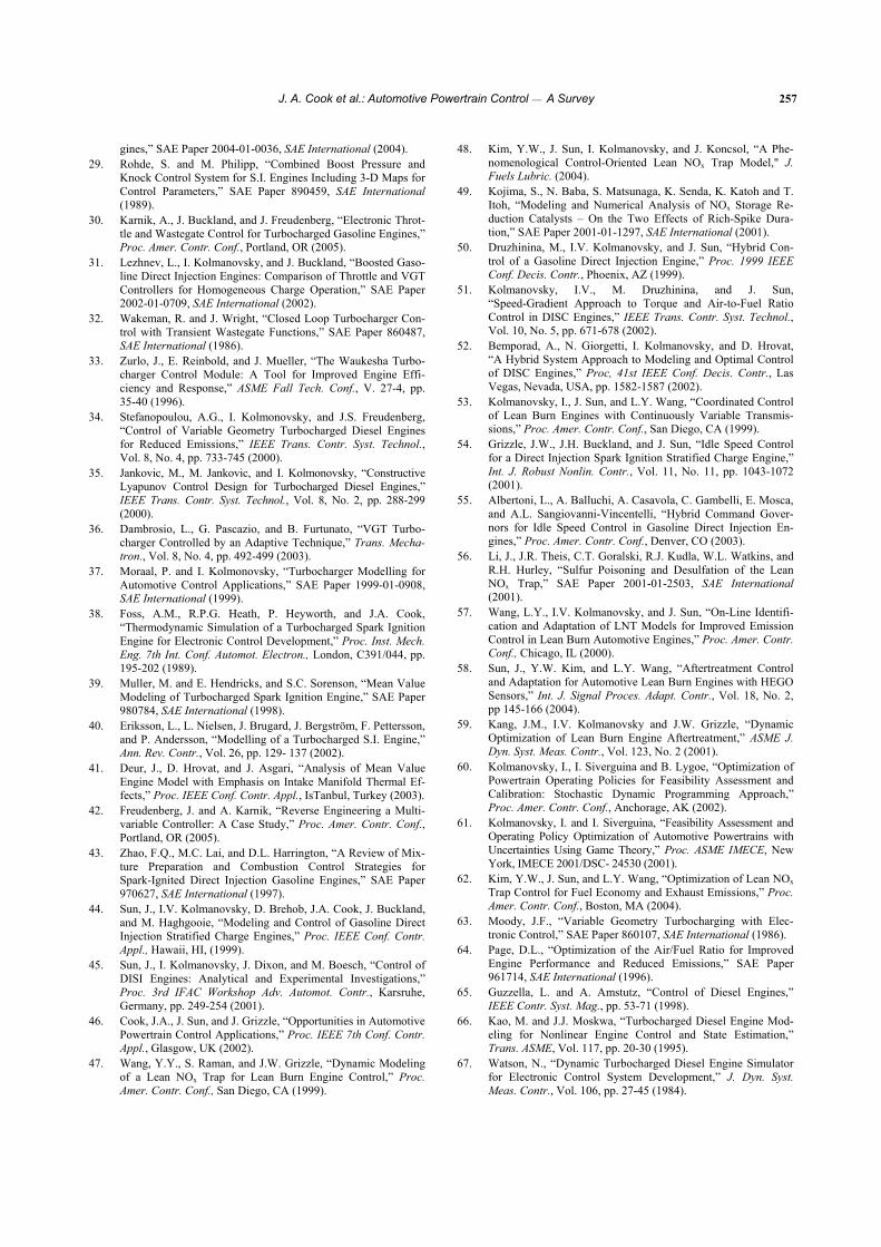
J. A. Cook et al.: Automotive Powertrain Control ⎯ A Survey 257
gines,” SAE Paper 2004-01-0036, SAE International (2004). 29. Rohde, S. and M. Philipp, “Combined Boost Pressure and
Knock Control System for S.I. Engines Including 3-D Maps for Control Parameters,” SAE Paper 890459, SAE International (1989).
30. Karnik, A., J. Buckland, and J. Freudenberg, “Electronic Throt-tle and Wastegate Control for Turbocharged Gasoline Engines,” Proc. Amer. Contr. Conf., Portland, OR (2005).
31. Lezhnev, L., I. Kolmanovsky, and J. Buckland, “Boosted Gaso-line Direct Injection Engines: Comparison of Throttle and VGT Controllers for Homogeneous Charge Operation,” SAE Paper 2002-01-0709, SAE International (2002).
32. Wakeman, R. and J. Wright, “Closed Loop Turbocharger Con-trol with Transient Wastegate Functions,” SAE Paper 860487, SAE International (1986).
33. Zurlo, J., E. Reinbold, and J. Mueller, “The Waukesha Turbo-charger Control Module: A Tool for Improved Engine Effi-ciency and Response,” ASME Fall Tech. Conf., V. 27-4, pp. 35-40 (1996).
34. Stefanopoulou, A.G., I. Kolmonovsky, and J.S. Freudenberg, “Control of Variable Geometry Turbocharged Diesel Engines for Reduced Emissions,” IEEE Trans. Contr. Syst. Technol., Vol. 8, No. 4, pp. 733-745 (2000).
35. Jankovic, M., M. Jankovic, and I. Kolmonovsky, “Constructive Lyapunov Control Design for Turbocharged Diesel Engines,” IEEE Trans. Contr. Syst. Technol., Vol. 8, No. 2, pp. 288-299 (2000).
36. Dambrosio, L., G. Pascazio, and B. Furtunato, “VGT Turbo-charger Controlled by an Adaptive Technique,” Trans. Mecha-tron., Vol. 8, No. 4, pp. 492-499 (2003).
37. Moraal, P. and I. Kolmonovsky, “Turbocharger Modelling for Automotive Control Applications,” SAE Paper 1999-01-0908, SAE International (1999).
38. Foss, A.M., R.P.G. Heath, P. Heyworth, and J.A. Cook, “Thermodynamic Simulation of a Turbocharged Spark Ignition Engine for Electronic Control Development,” Proc. Inst. Mech. Eng. 7th Int. Conf. Automot. Electron., London, C391/044, pp. 195-202 (1989).
39. Muller, M. and E. Hendricks, and S.C. Sorenson, “Mean Value Modeling of Turbocharged Spark Ignition Engine,” SAE Paper 980784, SAE International (1998).
40. Eriksson, L., L. Nielsen, J. Brugard, J. Bergström, F. Pettersson, and P. Andersson, “Modelling of a Turbocharged S.I. Engine,” Ann. Rev. Contr., Vol. 26, pp. 129- 137 (2002).
41. Deur, J., D. Hrovat, and J. Asgari, “Analysis of Mean Value Engine Model with Emphasis on Intake Manifold Thermal Ef-fects,” Proc. IEEE Conf. Contr. Appl., IsTanbul, Turkey (2003).
42. Freudenberg, J. and A. Karnik, “Reverse Engineering a Multi-variable Controller: A Case Study,” Proc. Amer. Contr. Conf., Portland, OR (2005).
43. Zhao, F.Q., M.C. Lai, and D.L. Harrington, “A Review of Mix-ture Preparation and Combustion Control Strategies for Spark-Ignited Direct Injection Gasoline Engines,” SAE Paper 970627, SAE International (1997).
44. Sun, J., I.V. Kolmanovsky, D. Brehob, J.A. Cook, J. Buckland, and M. Haghgooie, “Modeling and Control of Gasoline Direct Injection Stratified Charge Engines,” Proc. IEEE Conf. Contr. Appl., Hawaii, HI, (1999).
45. Sun, J., I. Kolmanovsky, J. Dixon, and M. Boesch, “Control of DISI Engines: Analytical and Experimental Investigations,” Proc. 3rd IFAC Workshop Adv. Automot. Contr., Karsruhe, Germany, pp. 249-254 (2001).
46. Cook, J.A., J. Sun, and J. Grizzle, “Opportunities in Automotive Powertrain Control Applications,” Proc. IEEE 7th Conf. Contr. Appl., Glasgow, UK (2002).
47. Wang, Y.Y., S. Raman, and J.W. Grizzle, “Dynamic Modeling of a Lean NOx Trap for Lean Burn Engine Control,” Proc. Amer. Contr. Conf., San Diego, CA (1999).
48. Kim, Y.W., J. Sun, I. Kolmanovsky, and J. Koncsol, “A Phe-nomenological Control-Oriented Lean NOx Trap Model," J. Fuels Lubric. (2004).
49. Kojima, S., N. Baba, S. Matsunaga, K. Senda, K. Katoh and T. Itoh, “Modeling and Numerical Analysis of NOx Storage Re-duction Catalysts – On the Two Effects of Rich-Spike Dura-tion,” SAE Paper 2001-01-1297, SAE International (2001).
50. Druzhinina, M., I.V. Kolmanovsky, and J. Sun, “Hybrid Con-trol of a Gasoline Direct Injection Engine,” Proc. 1999 IEEE Conf. Decis. Contr., Phoenix, AZ (1999).
51. Kolmanovsky, I.V., M. Druzhinina, and J. Sun, “Speed-Gradient Approach to Torque and Air-to-Fuel Ratio Control in DISC Engines,” IEEE Trans. Contr. Syst. Technol., Vol. 10, No. 5, pp. 671-678 (2002).
52. Bemporad, A., N. Giorgetti, I. Kolmanovsky, and D. Hrovat, “A Hybrid System Approach to Modeling and Optimal Control of DISC Engines,” Proc, 41st IEEE Conf. Decis. Contr., Las Vegas, Nevada, USA, pp. 1582-1587 (2002).
53. Kolmanovsky, I., J. Sun, and L.Y. Wang, “Coordinated Control of Lean Burn Engines with Continuously Variable Transmis-sions,” Proc. Amer. Contr. Conf., San Diego, CA (1999).
54. Grizzle, J.W., J.H. Buckland, and J. Sun, “Idle Speed Control for a Direct Injection Spark Ignition Stratified Charge Engine,” Int. J. Robust Nonlin. Contr., Vol. 11, No. 11, pp. 1043-1072 (2001).
55. Albertoni, L., A. Balluchi, A. Casavola, C. Gambelli, E. Mosca, and A.L. Sangiovanni-Vincentelli, “Hybrid Command Gover-nors for Idle Speed Control in Gasoline Direct Injection En-gines,” Proc. Amer. Contr. Conf., Denver, CO (2003).
56. Li, J., J.R. Theis, C.T. Goralski, R.J. Kudla, W.L. Watkins, and R.H. Hurley, “Sulfur Poisoning and Desulfation of the Lean NOx Trap,” SAE Paper 2001-01-2503, SAE International (2001).
57. Wang, L.Y., I.V. Kolmanovsky, and J. Sun, “On-Line Identifi-cation and Adaptation of LNT Models for Improved Emission Control in Lean Burn Automotive Engines,” Proc. Amer. Contr. Conf., Chicago, IL (2000).
58. Sun, J., Y.W. Kim, and L.Y. Wang, “Aftertreatment Control and Adaptation for Automotive Lean Burn Engines with HEGO Sensors,” Int. J. Signal Proces. Adapt. Contr., Vol. 18, No. 2, pp 145-166 (2004).
59. Kang, J.M., I.V. Kolmanovsky and J.W. Grizzle, “Dynamic Optimization of Lean Burn Engine Aftertreatment,” ASME J. Dyn. Syst. Meas. Contr., Vol. 123, No. 2 (2001).
60. Kolmanovsky, I., I. Siverguina and B. Lygoe, “Optimization of Powertrain Operating Policies for Feasibility Assessment and Calibration: Stochastic Dynamic Programming Approach,” Proc. Amer. Contr. Conf., Anchorage, AK (2002).
61. Kolmanovsky, I. and I. Siverguina, “Feasibility Assessment and Operating Policy Optimization of Automotive Powertrains with Uncertainties Using Game Theory,” Proc. ASME IMECE, New York, IMECE 2001/DSC- 24530 (2001).
62. Kim, Y.W., J. Sun, and L.Y. Wang, “Optimization of Lean NOx Trap Control for Fuel Economy and Exhaust Emissions,” Proc. Amer. Contr. Conf., Boston, MA (2004).
63. Moody, J.F., “Variable Geometry Turbocharging with Elec-tronic Control,” SAE Paper 860107, SAE International (1986).
64. Page, D.L., “Optimization of the Air/Fuel Ratio for Improved Engine Performance and Reduced Emissions,” SAE Paper 961714, SAE International (1996).
65. Guzzella, L. and A. Amstutz, “Control of Diesel Engines,” IEEE Contr. Syst. Mag., pp. 53-71 (1998).
66. Kao, M. and J.J. Moskwa, “Turbocharged Diesel Engine Mod-eling for Nonlinear Engine Control and State Estimation,” Trans. ASME, Vol. 117, pp. 20-30 (1995).
67. Watson, N., “Dynamic Turbocharged Diesel Engine Simulator for Electronic Control System Development,” J. Dyn. Syst. Meas. Contr., Vol. 106, pp. 27-45 (1984).
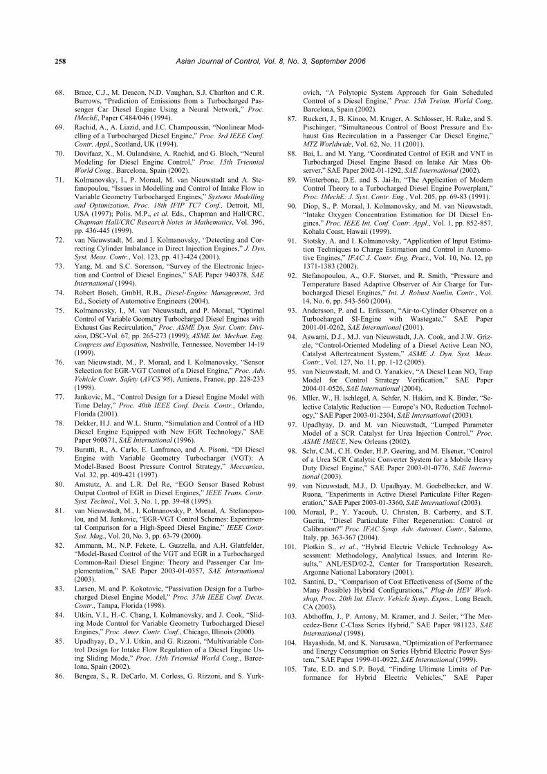
258 Asian Journal of Control, Vol. 8, No. 3, September 2006
68. Brace, C.J., M. Deacon, N.D. Vaughan, S.J. Charlton and C.R. Burrows, “Prediction of Emissions from a Turbocharged Pas-senger Car Diesel Engine Using a Neural Network,” Proc. IMechE, Paper C484/046 (1994).
69. Rachid, A., A. Liazid, and J.C. Champoussin, “Nonlinear Mod-elling of a Turbocharged Diesel Engine,” Proc. 3rd IEEE Conf. Contr. Appl., Scotland, UK (1994).
70. Dovifaaz, X., M. Oulandsine, A. Rachid, and G. Bloch, “Neural Modeling for Diesel Engine Control,” Proc. 15th Triennial World Cong., Barcelona, Spain (2002).
71. Kolmanovsky, I., P. Moraal, M. van Nieuwstadt and A. Ste-fanopoulou, “Issues in Modelling and Control of Intake Flow in Variable Geometry Turbocharged Engines,” Systems Modelling and Optimization, Proc. 18th IFIP TC7 Conf., Detroit, MI, USA (1997); Polis. M.P., et al. Eds., Chapman and Hall/CRC, Chapman Hall/CRC Research Notes in Mathematics, Vol. 396, pp. 436-445 (1999).
72. van Nieuwstadt, M. and I. Kolmanovsky, “Detecting and Cor-recting Cylinder Imbalance in Direct Injection Engines,” J. Dyn. Syst. Meas. Contr., Vol. 123, pp. 413-424 (2001).
73. Yang, M. and S.C. Sorenson, “Survey of the Electronic Injec-tion and Control of Diesel Engines,” SAE Paper 940378, SAE International (1994).
74. Robert Bosch, GmbH, R.B., Diesel-Engine Management, 3rd Ed., Society of Automotive Engineers (2004).
75. Kolmanovsky, I., M. van Nieuwstadt, and P. Moraal, “Optimal Control of Variable Geometry Turbocharged Diesel Engines with Exhaust Gas Recirculation,” Proc. ASME Dyn. Syst. Contr. Divi-sion, DSC-Vol. 67, pp. 265-273 (1999); ASME Int. Mechan. Eng. Congress and Exposition, Nashville, Tennessee, November 14-19 (1999).
76. van Nieuwstadt, M., P. Moraal, and I. Kolmanovsky, “Sensor Selection for EGR-VGT Control of a Diesel Engine,” Proc. Adv. Vehicle Contr. Safety (AVCS’98), Amiens, France, pp. 228-233 (1998).
77. Jankovic, M., “Control Design for a Diesel Engine Model with Time Delay,” Proc. 40th IEEE Conf. Decis. Contr., Orlando, Florida (2001).
78. Dekker, H.J. and W.L. Sturm, “Simulation and Control of a HD Diesel Engine Equipped with New EGR Technology,” SAE Paper 960871, SAE International (1996).
79. Buratti, R., A. Carlo, E. Lanfranco, and A. Pisoni, “DI Diesel Engine with Variable Geometry Turbocharger (VGT): A Model-Based Boost Pressure Control Strategy,” Meccanica, Vol. 32, pp. 409-421 (1997).
80. Amstutz, A. and L.R. Del Re, “EGO Sensor Based Robust Output Control of EGR in Diesel Engines,” IEEE Trans. Contr. Syst. Technol., Vol. 3, No. 1, pp. 39-48 (1995).
81. van Nieuwstadt, M., I. Kolmanovsky, P. Moraal, A. Stefanopou-lou, and M. Jankovic, “EGR-VGT Control Schemes: Experimen-tal Comparison for a High-Speed Diesel Engine,” IEEE Contr. Syst. Mag., Vol. 20, No. 3, pp. 63-79 (2000).
82. Ammann, M., N.P. Fekete, L. Guzzella, and A.H. Glattfelder, “Model-Based Control of the VGT and EGR in a Turbocharged Common-Rail Diesel Engine: Theory and Passenger Car Im-plementation,” SAE Paper 2003-01-0357, SAE International (2003).
83. Larsen, M. and P. Kokotovic, “Passivation Design for a Turbo-charged Diesel Engine Model,” Proc. 37th IEEE Conf. Decis. Contr., Tampa, Florida (1998).
84. Utkin, V.I., H.-C. Chang, I. Kolmanovsky, and J. Cook, “Slid-ing Mode Control for Variable Geometry Turbocharged Diesel Engines,” Proc. Amer. Contr. Conf., Chicago, Illinois (2000).
85. Upadhyay, D., V.I. Utkin, and G. Rizzoni, “Multivariable Con-trol Design for Intake Flow Regulation of a Diesel Engine Us-ing Sliding Mode,” Proc. 15th Triennial World Cong., Barce-lona, Spain (2002).
86. Bengea, S., R. DeCarlo, M. Corless, G. Rizzoni, and S. Yurk-
ovich, “A Polytopic System Approach for Gain Scheduled Control of a Diesel Engine,” Proc. 15th Treinn. World Cong, Barcelona, Spain (2002).
87. Ruckert, J., B. Kinoo, M. Kruger, A. Schlosser, H. Rake, and S. Pischinger, “Simultaneous Control of Boost Pressure and Ex-haust Gas Recirculation in a Passenger Car Diesel Engine,” MTZ Worldwide, Vol. 62, No. 11 (2001).
88. Bai, L. and M. Yang, “Coordinated Control of EGR and VNT in Turbocharged Diesel Engine Based on Intake Air Mass Ob-server,” SAE Paper 2002-01-1292, SAE International (2002).
89. Winterbone, D.E. and S. Jai-In, “The Application of Modern Control Theory to a Turbocharged Diesel Engine Powerplant,” Proc. IMechE: J. Syst. Contr. Eng., Vol. 205, pp. 69-83 (1991).
90. Diop, S., P. Moraal, I. Kolmanovsky, and M. van Nieuwstadt, “Intake Oxygen Concentration Estimation for DI Diesel En-gines,” Proc. IEEE Int. Conf. Contr. Appl., Vol. 1, pp. 852-857, Kohala Coast, Hawaii (1999).
91. Stotsky, A. and I. Kolmanovsky, “Application of Input Estima-tion Techniques to Charge Estimation and Control in Automo-tive Engines,” IFAC J. Contr. Eng. Pract., Vol. 10, No. 12, pp 1371-1383 (2002).
92. Stefanopoulou, A., O.F. Storset, and R. Smith, “Pressure and Temperature Based Adaptive Observer of Air Charge for Tur-bocharged Diesel Engines,” Int. J. Robust Nonlin. Contr., Vol. 14, No. 6, pp. 543-560 (2004).
93. Andersson, P. and L. Eriksson, “Air-to-Cylinder Observer on a Turbocharged SI-Engine with Wastegate,” SAE Paper 2001-01-0262, SAE International (2001).
94. Aswami, D.J., M.J. van Nieuwstadt, J.A. Cook, and J.W. Griz-zle, “Control-Oriented Modeling of a Diesel Active Lean NOx Catalyst Aftertreatment System,” ASME J. Dyn. Syst. Meas. Contr., Vol. 127, No. 11, pp. 1-12 (2005).
95. van Nieuwstadt, M. and O. Yanakiev, “A Diesel Lean NOx Trap Model for Control Strategy Verification,” SAE Paper 2004-01-0526, SAE International (2004).
96. Mller, W., H. lschlegel, A. Schfer, N. Hakim, and K. Binder, “Se-lective Catalytic Reduction ⎯ Europe’s NOx Reduction Technol-ogy,” SAE Paper 2003-01-2304, SAE International (2003).
97. Upadhyay, D. and M. van Nieuwstadt, “Lumped Parameter Model of a SCR Catalyst for Urea Injection Control,” Proc. ASME IMECE, New Orleans (2002).
98. Schr, C.M., C.H. Onder, H.P. Geering, and M. Elsener, “Control of a Urea SCR Catalytic Converter System for a Mobile Heavy Duty Diesel Engine,” SAE Paper 2003-01-0776, SAE Interna-tional (2003).
99. van Nieuwstadt, M.J., D. Upadhyay, M. Goebelbecker, and W. Ruona, “Experiments in Active Diesel Particulate Filter Regen-eration,” SAE Paper 2003-01-3360, SAE International (2003).
100. Moraal, P., Y. Yacoub, U. Christen, B. Carberry, and S.T. Guerin, “Diesel Particulate Filter Regeneration: Control or Calibration?” Proc. IFAC Symp. Adv. Automot. Contr., Salerno, Italy, pp. 363-367 (2004).
101. Plotkin S., et al., “Hybrid Electric Vehicle Technology As-sessment: Methodology, Analytical Issues, and Interim Re-sults,” ANL/ESD/02-2, Center for Transportation Research, Argonne National Laboratory (2001).
102. Santini, D., “Comparison of Cost Effectiveness of (Some of the Many Possible) Hybrid Configurations,” Plug-In HEV Work-shop, Proc. 20th Int. Electr. Vehicle Symp. Expos., Long Beach, CA (2003).
103. Abthoffm, J., P. Antony, M. Kramer, and J. Seiler, “The Mer-cedez-Benz C-Class Series Hybrid,” SAE Paper 981123, SAE International (1998).
104. Hayashida, M. and K. Narusawa, “Optimization of Performance and Energy Consumption on Series Hybrid Electric Power Sys-tem,” SAE Paper 1999-01-0922, SAE International (1999).
105. Tate, E.D. and S.P. Boyd, “Finding Ultimate Limits of Per-formance for Hybrid Electric Vehicles,” SAE Paper
J. A. Cook et al.: Automotive Powertrain Control ⎯ A Survey 259
2000-01-3099, SAE International (2000). 106. Cho, C.P., W. Wylam, and R. Johnston, “The Integrated Starter
Alternator Damper: The First Step Toward Hybrid Electric Ve-hicles,” SAE Paper 2000-01-1571, SAE International (2000).
107. Gale, A. and D. Brigham, “Starter/Alternator Design for Opti-mized Hybrid Fuel Economy,” SAE Paper 2000-01- C061, SAE International (2000).
108. Ogawa, H., M. Matsuki, and T. Eguchi, “Development of a Power Train for the Hybrid Automobile ⎯ The Civic Hybrid,” SAE Paper 2003-01-0083, SAE International (2003).
109. Muta, K., M. Yamazaki, and J. Tokieda, “Development of New-Generation Hybrid System THS II ⎯ Drastic Improve-ment of Power Performance and Fuel Economy,” SAE Paper 2004-01-0064, SAE International (2004).
110. Holmes, A.G., D. Klemen, and M.R. Schmidt, “Electrically Variable Transmission with Selective Input Split, Compound Split, Neutral and Reverse Modes,” US Patent No. 6, 527,658 (2001).
111. Rizoulis, D., J. Burl, and J. Beard, “Control Strategies for a Series-Parallel Hybrid Electric Vehicle,” SAE Paper 2001-01-1354, SAE International (2001).
112. Baumann, B.M., et al., “Mechatronic Design and Control of Hybrid Electric Vehicles,“ IEEE/ASME Trans. Mechatron., Vol. 5, No. 1, pp. 58-72 (2000).
113. Farrall, S.D. and R. P. Jones, “Energy Management in an Automotive Electric/Heat Engine Hybrid Powertrain Using Fuzzy Decision Making,” Proc. Int. Symp. Intell. Contr., Chi-cago, IL (1993).
114. Kim, C., E. NamGoong, and S. Lee, “Fuel Economy Optimiza-tion for Parallel Hybrid Vehicles with CVT,” SAE Paper 1999-01-1148, SAE International (1999).
115. Paganelli, G., G. Ercole, A. Brahma, Y. Guezennec, and G. Rizzoni, “A General Formulation for the Instantaneous Control of the Power Split in Charge-Sustaining Hybrid Electric Vehi-cles.” Proc. 5th Int. Symp. Adv. Vehicle Contr., Ann Arbor, MI (2000).
116. Johnson, V.H., K.B. Wipke, and D.J. Rausen, “HEV Control Strategy for Real-Time Optimization of Fuel Economy and Emissions,” SAE Paper 2000-01-1543, SAE International (2000).
117. Brahma, A., Y. Guezennec, and G. Rizzoni, “Dynamic Optimi-zation of Mechanical Electrical Power Flow in Parallel Hybrid Electric Vehicles,” Proc. 5th Int. Symp. Adv. Vehicle Contr, Ann Arbor, MI (2000).
118. Zoelch, U. and D. Scroeder, “Dynamic Optimization Method for Design and Rating of the Components of a Hybrid Vehicle,” Int. J. Vehicle Design, Vol. 19, No. 1, pp. 1-13 (1998).
119. Lin, C.-C., H. Peng, J.W. Grizzle, J. Liu, and M. Bus-diecker, “Control System Development for an Ad-vanced-Technology Medium-Duty Hybrid Electric Truck,” Int. Truck Bus Meet. Exhib., Fort Worth, TX, SAE Paper 2003-01-3369, SAE International (2003).
120. Lin, C.-C., H. Peng, J.W. Grizzle, and J. Kang, “Power Man-agement Strategy for a Parallel Hybrid Electric Truck,” IEEE Trans. Contr. Syst. Technol., Vol. 11, pp. 839-849 (2003).
121. Lin, C.-C., H. Peng, and J.W. Grizzle, “A Stochastic Control Strategy for Hybrid Electric Vehicles,” Proc. Amer. Contr. Conf., Boston, MA (2004).
122. Bertsekas, D.P., Dynamic Programming and Optimal Control, Athena Scientific (1995).
123. Yang, W.C., B. Bates, N. Fletcher, and R. Pow, “Control Chal-lenges and Methodologies in Fuel Cell Vehicle Development,” SAE Paper 98C054, SAE International (1998).
124. Stefanopoulou, A.G., “Mechatronics in Fuel Cell Systems,” Proc. IFAC Symp. Mechatron., Sydney (2004).
125. Pukrushpan, J.T., A.G. Stefanopoulou, and H. Peng, Control of Fuel Cell Power Systems: Principles, Modeling, Analysis, and
Feedback Design, Springer Verlag (2004). 126. Boettner, D.D., G. Paganelli, Y.G. Guezennec, G. Rizzoni, and
M.J. Moran, “Proton Exchange Membrane (PEM) Fuel Cell System Model for Automotive Vehicle Simulation and Con-trol,” Proc. ASME Int. Mech. Eng. Cong. Expos. (2001).
127. Eborn, J., L. Pedersen, C. Haugstetter, and S. Ghosh, “System Level Dynamic Modeling of Fuel Cell Power Plants,” Proc. Amer. Contr. Conf., Denver, CO (2003).
128. Gelfi, S., A.G. Stefanopoulou, J. Pukrushpan, and H. Peng, “Dynamics and Control of Low and High Pressure Fuel Cells,” Proc. Amer. Contr. Conf., Denver, CO (2003).
129. Pukrushpan, J.T., A.G. Stefanopoulou, S. Varigonda, L.M. Pedersen, S. Ghosh, and H. Peng, “Control of Natural Gas Catalytic Partial Oxidation for Hydrogen Generation in Fuel Cell Applications,” Proc. Amer. Contr. Conf., Denver, CO (2003).
130. Tsourapas, V., J. Sun, and A.G. Stefanopoulou, “Modeling and Dynamics of a Fuel Cell Combined Heat Power System for Marine Applications,” Proc. 8th WSEAS Int. Conf. Syst. (2004).
131. McKay, D.A. and A.G. Stefanopoulou, “Parameterization and Validation of a Lumped Parameter Diffusion Model for Fuel Cell Stack Membrane Humidity Estimation,” Proc. Amer. Contr. Conf., Boston, MA (2004).
132. Okada, T., G. Xie, and M. Meeg, “Simulation for Water Man-agement in Membranes for Polymer Electrolyte Fuel Cells,” Electrochimica Acta, Vol. 43, No. 14-15, pp. 2141-2155 (1998).
133. Chen, D. and H. Peng, “Modeling and Analysis of PEM Fuel Cell Humidifiers,” Proc. ASME Int. Mech. Eng. Cong. Expos., Anaheim, California, USA, IMECE2004- 60029 (2004).
134. Wang, C.Y., “Fundamental Models for Fuel Cell Engineering,” Chem. Rev. (2004).
135. Sun, J. and I. Kolmanovsky, “A Robust Load Governor for Fuel Cell Oxygen Starvation Protection,” IEEE Trans. Contr. Syst. Technol., Vol. 13, No. 6, pp. 911-920 (2005).
136. Vahidi, A., A.G. Stefanopoulou, and H. Peng, “Model Predic-tive Control for Starvation Prevention in a Hybrid Fuel Cell System,” Proc. Amer. Contr. Conf., Boston, MA (2004).
137. Pukrushpan, T.J., A.G. Stefanopoulou, and H. Peng, “Control-ling Fuel Cell Breathing,” IEEE Contr. Sys. Mag. (2004).
138. Guezennec, Y. and T.Y. Choi, “Supervisory Control of Fuel Cell Vehicles and Its Link to Overall System Efficiency and Low-Level Control Requirements,” Proc. Amer. Contr. Conf., Denver, CO (2003).
139. Matsumoto, T., N. Watanabe, H. Sugiura, and T. Ishikawa, “Development of Fuel Cell Hybrid Vehicle,” SAE Paper 2002-01-0096, SAE International (2002).
140. Ishikawa, T., S. Hamaguchi, T. Shimizu, T. Yano, S. Sasaki, K. Kato, M. Ando, and H. Yoshida, “Development of Next Gen-eration Fuel-Cell Hybrid System- Consideration of High Volt-age System,” SAE Paper 2004-01-1304, SAE International (2004).
141. Ohkawa, A., “Electric Power Control System for a Fuel Cell Vehicle Employing Electric Double-Layer Capacitor,” SAE Paper 2004-01-1006, SAE International (2004).
142. Zolot, M., “Dual-Source Energy Storage ⎯ Control and Per-formance Advantages in Advanced Vehicles,” Proc. 20th Electr. Vehicle Symp. (2003).
143. Peng, H., M. Kim, C. Lin, and J. Grizzle, “Integrated Dynamic Simulation Model with Supervisory Control Strategy for a PEM Fuel Cell Hybrid Vehicle,” Proc. ASME Int. Mech. Eng. Cong. Expos., Anaheim, California, USA, IMECE2004-61775 (2004).
144. Arcak, M., H. Görgün, L.M. Pedersen, and S. Varigonda, “An Adaptive Observer Design for Fuel Cell Hydrogen Estimation,” Proc. Amer. Contr. Conf., Denver, CO (2003).
145. Rodatz, P., A. Tsukada, M. Mladek, and L. Guzzella, “Effi-ciency Improvement by Pulsed Hydrogen Supply in PEM Fuel Cell Systems,” Proc. 15th IFAC World Cong. (2002).
260 Asian Journal of Control, Vol. 8, No. 3, September 2006
Jeffrey Cook is a Technical Leader at the Ford Motor Company Research and Innovation Center. He is an Adjunct Professor of Electrical Engineering and Computer Science at the University of Michigan. His research addresses mod-eling and control of automotive power-
trains for improved fuel economy and emissions, and im-provements in systems engineering processes for the design of automotive controls. He holds 25 patents on automotive technology. He is a Fellow of the IEEE and one of three recipients of the 2003 IEEE Control Systems Technology Award. He is a Subject Editor for the International Journal of Robust and Nonlinear Control.
Jing Sun received her Ph.D. degree from University of Southern California in 1989, and her B.S. and M.S. degrees from Univer-sity of Science and Technology of China in 1982 and 1984, respectively. From 1989- 1993, she was an assistant professor in Elec-trical and Computer Engineering Department, Wayne State University. She joined Ford
Research Laboratory in 1993 where she worked in the Power-train Control Systems Department. After spending almost 10 years in industry, she came back to academia and joined the faculty of the College of Engineering at University of Michigan in 2003 as an associate professor. Her research interests include system and control theory and its applications to marine and automotive propulsion systems.
She holds over 30 US patents and has co-authored a text-book on Robust Adaptive Control. She is an IEEE Fellow and one of the three recipients of the 2003 IEEE Control System Technology Award. She is also a subject editor for International Journal of Adaptive Control and Signal Processing.
Julia Buckland received B.S. and M.S. de-grees in Aerospace Engineering from the University of Cincinnati in 1988 and 1993 respectively. She worked several years in the defense industry developing flight control systems for advanced military aircraft. In 1994, she joined Ford Motor Company,
where she is currently a technical expert in the Powertrain Con-trols R&A Department. Her work focuses on modeling and control of advanced technology powertrain systems.
Ilya V. Kolmanovsky studied as an under-graduate at Moscow Aviation Institute, Rus-sia. He received the M.S. degree and the Ph.D. degree in aerospace engineering, in 1993 and 1995, respectively, and the M.A. degree in mathematics, in 1995, all from the University of Michigan, Ann Arbor. He is
currently a Technical Leader in Powertrain Control at Ford Research & Advanced Engineering of Ford Motor Company, Dearborn, MI. In addition to expertise in the automotive en-gine and powertrain control, his research interests include potential of advanced control techniques as an enabling tech-nology for advanced automotive systems, and several areas of control theory, which include constrained control, optimiza-tion-based and model-predictive control, and control of nonlinear mechanical, nonholonomic, and underactuated sys-tems.
Dr. Kolmanovsky is the Chair of IEEE CSS Technical Committee on Automotive Control. He has served as an Associ-ate Editor of IEEE CSS Conference Editorial Board (1997- 1999), IEEE Transactions On Control Systems Technology (2002-2004), IEEE Transactions On Automatic Control (2005-present), and he was a Program Committee Member of American Control Conference in 1997, 1999, and 2004. He is the recipient of 2002 Donald P. Eckamn Award of American Automatic Control Council for contributions to nonlinear con-trol and for pioneering work in automotive engine control of powertrain systems and of 2002 IEEE Transactions On Control Systems Technology Outstanding Paper Award.
Huei Peng received the Ph.D. degree in me-chanical engineering from the University of California, Berkeley, in 1992. He is currently a Professor with the Department of Mechanical Engineering, University of Michigan, Ann Ar-bor. His research interests include adaptive con-
trol and optimal control, with emphasis on their applications to vehicular and transportation systems. He has been an active member of SAE and the ASME Dynamic System and Control Division. Dr. Peng has served as the chair of the ASME DSCD Transportation Panel from 1995 to 1997. He is currently an Associate Editor for the IEEE/ASME Transactions On Mecha-tronics. He received the National Science Foundation (NSF) Career award in 1998.
Jessy W. Grizzle received the Ph.D. in elec-trical engineering from The University of Texas at Austin in 1983. Since September 1987, he has been with The University of Michigan, Ann Arbor, where he is a Profes-sor of Electrical Engineering and Computer Science. He jointly holds fourteen patents
dealing with emissions reduction through improved control system design. He received the Paper of the Year Award from the IEEE Vehicular Technology Society in 1993, was elected a Fellow of the IEEE in 1997, received the 2002 George S. Ax-elby Award and the 2003 Control Systems Technology Award.