ewen avenue reconstruction project (phase 2), city of new
TRANSCRIPT

CORPORATION OF THE CITY OF NEW WESTMINSTER
CONTRACT No. NWIT-15-09
Ewen Avenue Reconstruction Project (Phase 2), City of New Westminster
Watermain (Phase 2 & 3) and GVWD Queensborough Main No. 2
(Phase 2 & 3)
MMCD 2009 Edition Reference No. NWIT-15-09

Page 1
Title Dwg. No. Pages
Table of Contents Page 1
Invitation to Tenderers Page 1
INSTRUCTIONS TO TENDERERS: PART I
1.0 Introduction IT Page 1
2.0 Tender Documents IT Page 2
3.0 Submission of Tenders IT Page 2
4.0 Additional Instructions to Tenderers IT Page 3-8
Instructions to Tenderers: Part II (MMCD, Platinum Edition) Not Reproduced
FORM OF TENDER
Form of Tender FT Page 1-4
Appendix 1 – Schedule of Quantities and Prices FT Page 5-33
Appendix 2 – Preliminary Construction Schedule FT Page 34
Appendix 3 – Experience of Superintendent FT Page 35
Appendix 4 – Comparable Work Experience FT Page 36
Appendix 5 – Subcontractors FT Page 37
Appendix 6 – Force Account Labour Rates FT Page 38
Appendix 7 – Declaration – Living Wage Employer FT Page 39
AGREEMENT
Agreement between Contractor and Owner AGT Page 1-5
Schedule 1 – Schedule of Contract Documents AGT Page 6
Schedule 2A – List of Supplementary Conditions, Specifications and Drawings AGT Page 7
Schedule 2B – List of Contract Drawings, Supplementary Detail Drawings & Reference Drawings AGT Page 8-17
MMCD 2009 Edition Reference No. NWIT-15-09

Page 2
Title Dwg. No. Pages
SUPPLEMENTARY CONDITIONS, SPECIFICATIONS & DRAWINGS
Supplementary General Conditions SGC Page 1–8
General Conditions (MMCD, Platinum Edition) Not Reproduced
Supplementary Specifications – CNW SSPEC Page 1-55
Standard Specifications (MMCD, Platinum Edition) Not Reproduced
CNW Schedule C – Supplementary Specifications and Detail Drawings Not Reproduced
CNW Irrigation Standards and Specifications (2013) Not Reproduced
CNW Irrigation Standards and Specifications – 2 Wire Decoder Systems (2014) Not Reproduced
Standard Detail Drawings (MMCD, Platinum Edition) Not Reproduced
BC Hydro Underground Civil Manual (Recent) Not Reproduced
TAC MUTCD Recent Edition Not Reproduced
TAC Bikeway Traffic Control Guide for Canada Recent Edition Not Reproduced
BC MoTI Bicycle Traffic Control Guidelines Recent Edition Not Reproduced
BCNTA/BCSLA Standards Current Edition Not Reproduced
Greater Vancouver Water District Supplemental to City of New Westminster Tender No. NWIT-15-09 On FTP Site
ATTACHMENTS – On FTP Site
Attachment 1 – Contract Drawings On FTP Site
ADDITIONAL ATTACHMENT – REFERENCE DOCUMENTS – On FTP Site
Attachment 2 – GEOTECHNICAL REPORT BY BRAUN, DATED AUGUST 20, 2014 On FTP Site
Attachment 3 – Not Used
Attachment 4 – GEOTECHNICAL REPORT BY AMEC FOR METRO VANCOUVER & CNW MAINS, DATED APRIL 14, 2015
On FTP Site
MMCD 2009 Edition Reference No. NWIT-15-09
Page 3
Title Dwg. No. Pages
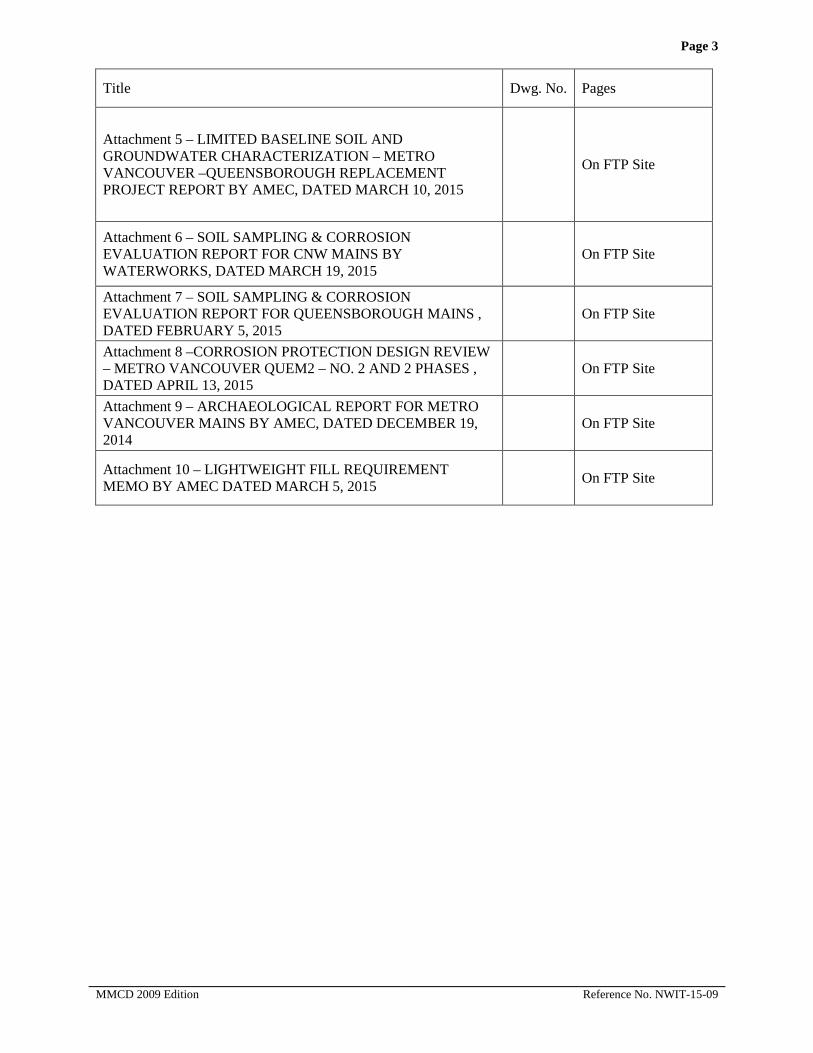
Attachment 5 – LIMITED BASELINE SOIL AND GROUNDWATER CHARACTERIZATION – METRO VANCOUVER –QUEENSBOROUGH REPLACEMENT PROJECT REPORT BY AMEC, DATED MARCH 10, 2015
On FTP Site
Attachment 6 – SOIL SAMPLING & CORROSION EVALUATION REPORT FOR CNW MAINS BY WATERWORKS, DATED MARCH 19, 2015
On FTP Site
Attachment 7 – SOIL SAMPLING & CORROSION EVALUATION REPORT FOR QUEENSBOROUGH MAINS , DATED FEBRUARY 5, 2015
On FTP Site
Attachment 8 –CORROSION PROTECTION DESIGN REVIEW – METRO VANCOUVER QUEM2 – NO. 2 AND 2 PHASES , DATED APRIL 13, 2015
On FTP Site
Attachment 9 – ARCHAEOLOGICAL REPORT FOR METRO VANCOUVER MAINS BY AMEC, DATED DECEMBER 19, 2014
On FTP Site
Attachment 10 – LIGHTWEIGHT FILL REQUIREMENT MEMO BY AMEC DATED MARCH 5, 2015 On FTP Site
MMCD 2009 Edition Reference No. NWIT-15-09

INVITATION TO TENDERS
CORPORATION OF THE CITY OF NEW WESTMINSTER (THE OWNER)
Contract: Ewen Avenue Reconstruction Project (Phase 2), City of New Westminster Watermain (Phase 2 & 3) and GVWD Queensborough Main No. 2 (Phase 2 & 3)
Reference No: NWIT-15-09
The Owner invites tenders for:
Construction of approximately 1.2 km of Ewen Avenue Road Reconstruction Phase 2 from Jardine Street to Derwent Way which includes Roadworks and multi-use path, Storm Sewers, Sanitary Forcemain (from Jardine Street to Wood Street and along Wood Street), Street & Pathway Lighting, Traffic Signals, City of New Westminster Underground Electrical Distribution, Shaw Underground and Spare Ducts, City of New Westminster Phase 2 Watermains, GVWD Queensborough Main No. 2 – Phase 2.
This work also include the following Optional Packages:
• Sanitary Forcemain – Phase 2B – (Wood Street to Derwent Way) ;
• City of New Westminster Watermains -Phase 3 (Jardine Street to Boundary Road);
• GVWD Queensborough Main No. 2 Phase 3 (Jardine Street to Boundary Road).
Copies of the Contract Documents are available for download from the City of New Westminster Purchasing site at: http://www.newwestcity.ca/business/bid_opportunities/request_for_bids__proposals_-_open.php Tender Drawings and Attachments are available for download from this site: https://fileshare.newwestcity.ca/link/2XlFe1mkcLUosLDVPRaRHj Tenderers are responsible to check for all subsequent addendums/amendments on the City’s Purchasing web page and/or BC Bid and respond according to the Invitation to Tender documents.
Tenders are scheduled to close at:
Tender Closing Date: May 20, 2015 Tender Closing Time: 3:00 pm (Local Time) Address:
City of New Westminster Main Information Desk 511 Royal Avenue New Westminster, BC V3L 1H9
Attention: Purchasing Manager A tender shall be accompanied by a Bid Bond (or Certified Cheque) in the amount of ten percent (10%) of the Tender Price payable to the Corporation of the City of New Westminster. The successful tenderer will be required to provide a Performance and Labour and Material Payment Bond each in the amount of fifty percent (50%) of the Tender Price. An Agreement of Surety to bond shall accompany the tender submitted.
MMCD 2009 Edition Reference No. NWIT-15-09

Inquiries regarding this tender may be directed to:
Heather Rossi, Intermediate Buyer City of New Westminster email: [email protected]
The lowest or any Tender may not necessarily be accepted and the City will not be responsible for any cost incurred by the Tenderer in preparing the Tender. Tender award will be contingent on budget approval from the City of New Westminster Council. If the value of the contract(s) resulting from this invitation to tender exceeds the thresholds stipulated in Annex 502.4 of the Agreement on Internal Trade, then all provisions of the Agreement on Internal Trade will apply.
MMCD 2009 Edition Reference No. NWIT-15-09

INSTRUCTIONS TO TENDERERS
Instructions to Tender, Part I
MMCD 2009 Edition Reference No. NWIT-15-09

IT PART 1 PAGE 1
INSTRUCTIONS TO TENDERERS – PART 1
(TO BE READ WITH “INSTRUCTIONS TO TENDERERS – PART II” CONTAINED IN THE EDITION OF THE PUBLICATION “MASTER MUNICIPAL CONSTRUCTION DOCUMENTS” SPECIFIED IN
ARTICLE 2.2 BELOW)
CORPORATION OF THE CITY OF NEW WESTMINSTER
(THE OWNER)
Contract: Ewen Avenue Reconstruction Project (Phase 2), City of New Westminster Watermain (Phase 2 & 3) and GVWD Queensborough Main No. 2 (Phase 2 & 3)
Reference No: NWIT-15-09 1.0 Introduction 1.1 These Instructions apply to and govern the preparation of tenders for this
Contract. The Contract is generally for the following work:
Section 1 – 4: Reconstruction and widening which includes intersection modification of Howe Street & Ewen Avenue, two thru lanes, centre medians, two park lanes, multi-use pathway, concrete sidewalks, curb extensions, raised intersection, speed tables, raised crosswalks, landscaping, irrigation, and as shown on the contract drawings. Section 5 – Utilities Storm Sewers, Manholes and Catchbasins
Watermains – Phase “2”
Sanitary Forcemains – Phase “2A”
Sanitary Forcemains – Phase “2B” – Optional
Section 6 – Street and Pathway Lighting Section 7 – Traffic Signals Section 8 – City of New Westminster Underground Electrical Distribution Section 9 – Shaw Structures and Duct Installation Section 10 – Spare Ducts Section 11 – Utilities Part 2 (Waterworks – Phase”3”) – Optional Section 12 – GVWD QUEM2 – “Phase 2” Section 13 – GVWD QUEM2 – “Phase 3”-Optional (“Work” means both the City Work and GVWD Work unless the context requires that it mean either the City Work or the GVWD Work alone)
1.2 Direct all inquiries regarding the Contract, to: Heather Rossi, Intermediate Buyer City of New Westminster 511 Royal Ave, New Westminster, BC, V3L 1H9 email: [email protected]
MMCD 2009 Edition Reference No. NWIT-15-09

IT PART 1 PAGE 2 2.0 Tender
Documents 2.1 The tender documents, which a tenderer should review to prepare a tender,
consist of all of the Contract Documents listed in Schedule 1 entitled “Schedule of Contract Documents”. Schedule 1 is attached to the Agreement which is included as part of the tender package. The Contract Documents include the drawings listed in Schedule 2 to the Agreement, entitled “List of Contract Drawings”.
2.2 A portion of the Contract Documents are included by reference. Copies of these documents have not been included with the tender package. These documents are the Instructions to Tenderers – Part II, General Conditions, Specifications, and Standard Detail Drawings. They are those contained in the publication entitled “Master Municipal Construction Documents – General Conditions, Specifications, and Standard Detail Drawings”. Refer to Schedule 1 to the Agreement or, if not specified in Schedule 1, then the applicable edition shall be the most recent edition as of the date of the Tender Closing Date. All sections of this publication are by reference included in the Contract Documents. Copies of the Master Municipal Construction Document (Platinum Edition) can be obtained at:
Support Services Unlimited #102 – 211 Columbia Street Vancouver, BC, V6A 2R5 604-681-0295
2.3 Any additional information made available to tenderers prior to the Tender Closing Time by the Owner or representative of the Owner, such as geotechnical reports or as-built plans, which is not expressly included in Schedule 1 or Schedule 2 to the Agreement, is not included in the Contract Documents. Such additional information is made available only for the assistance of tenderers who must make their own judgment about its reliability, accuracy, completeness and relevance to the Contract, and neither the Owner nor any representative of the Owner gives any guarantee or representation that the additional information is reliable, accurate, complete or relevant.
3.0 Submission of Tenders
3.1 Tenders must be submitted in a sealed envelope, marked on the outside with the above Contract Title and Reference No., and must be received by the office of: The Purchasing Department On or before: Tender Closing Time: 3:00 pm (Local Time) Tender Closing Date: May 20, 2015
Address: City of New Westminster Information Desk 511 Royal Avenue New Westminster, BC V3L 1H9
Attention: Purchasing Manager
MMCD 2009 Edition Reference No. NWIT-15-09

IT PART 1 PAGE 3 3.2 Late tenders will not be accepted or considered, and will be returned
unopened.
3.3 Facsimile electronic mail or other unsealed bids will not be accepted.
3.4 The City will not open this Tender in public.
4.0 Additional Instructions to Tenderers
4.1 IT 5 (add following Appendices to IT 5.3) Add Appendix 6: Force Account Labour Rates Add Appendix 7: Declaration – Living Wage Employer (required before award)
Award 4.2 IT 15.5 (add clause 15.5 as follows) Tenders will be evaluated based on the total costs of Part I and Part II, and information provided in the form of Tender Appendices. In exercising its discretion, the Owners will have regard to the information provided by the Tenderer in the Appendices to the Form of Tender as described under IT 5, and may also have regard to any information obtained by the Owner in evaluating such tender information, as well as the Owner’s previous experience, if any, with the Tenderer. In exercising its discretion the Owner may consider, but is not limited to, the following criteria in addition to the Tender Price: a) the proven experience of the Tenderer, and any listed subcontractors to
do the Work; b) the Tenderer’s ability to complete the Work within the Preliminary
Construction Schedule; c) the Tenderer’s ability to work effectively with the Owner, its
consultants and representatives; d) the Tenderer’s ability to manage and do the work effectively using the
named superintendent and submitted contractors and subcontractors; e) the Tenderer’s history on other projects including with respect to
quality of work, changes in the work, force account work, and the contract administration costs of the Owner;
f) the nature of any legal proceedings undertaken by the Tenderer, or any officer or director of the Tenderer or affiliate of the Tenderer, directly (or indirectly through another corporation) against the Owner, Metro Vancouver, the Greater Vancouver Regional District or Greater Vancouver Water District within the previous five years of the Invitation to Tender;
g) litigation and on-going unresolved claims; a. in addition to any other provision of this tender document, and
without limiting the City’s discretion under any other provision of this tender document, the City may, in its absolute discretion, reject a tender if:
i. the Tenderer, or any officer or director of the Tenderer, is or has been engaged directly or indirectly in a legal action against the City or Metro Vancouver, Greater Vancouver Regional District or Greater Vancouver Water District in
MMCD 2009 Edition Reference No. NWIT-15-09

IT PART 1 PAGE 4
relation to any matter; or, ii. the Tenderer has current unresolved extra work claims
totalling in excess of $100,000.00 beyond 90 days of contract substantial completion for any construction project with the City or Metro Vancouver, Greater Vancouver Regional District or Greater Vancouver Water District.
b. in determining whether or not to reject a tender under this section, the City will consider whether the litigation or unresolved extra work claim is likely affect the Tenderer’s ability to work with the City or GVWD or their respective employees, consultants and representatives and whether the City or GVWD’s experience with the Tenderer indicates an unusual risk the City or GVWD will incur increased staff and legal costs in the administration of the contract if awarded to the Tenderer.
The Owner will, following receipt of an acceptable tender, issue in writing a Notice of Acceptance to the successful tenderer. This Notice will be given as soon as possible following the closing of tenders and, unless otherwise agreed to by the tenderer, not later than sixty (60) days following the Tender Closing Date. The Owner may, prior to and after Contract Award, negotiate changes to the scope of the Work, the type of materials, the specifications or any conditions with the low tenderer without having any duty or obligation to advise any other tenderer or to allow them to vary their Tender Prices as a result of such changes and the Owner shall have no liability to any other tenderer as a result of such negotiations or modifications. The award of this Contract is subject to approval of the Owner and to the availability of sufficient funds to complete the Work. The Owner, on its own behalf or on behalf of GVWD, may delete certain portions of the Work if Tender Prices exceed the available budget.
Freedom of Information
4.3 IT 18 (add clause 18 as follows)
The City of New Westminster and GVWD are subject to the Province of British Columbia Freedom of Information and Protection of Privacy Act. All documents will be received and held in confidence by the City of New Westminster and GVWD and the information will not be disclosed, except to the extent necessary for carrying out the City or GVWD's purposes or as required by law.
Living Wage Information
4.4 IT 19 (add clause 19 as follows) Effective January 1, 2011, the City of New Westminster became a “Living Wage Employer” (see Form of Tender – Appendix 7). As such, the City has established a Living Wage Policy that requires all firms that are contracted by the City to provide services on City premises, to pay their employees, who perform said service on City property, a Living Wage as calculated by the Living Wage for Families Campaign. The figure for 2015 for the Lower Mainland is $20.10, assuming no benefits are provided by the employer.
MMCD 2009 Edition Reference No. NWIT-15-09

IT PART 1 PAGE 5
In order to determine an employee’s hourly rate with benefits the Living Wage for Families has created a Living Wage Calculator to assist with this determination. Please access the following website to determine your compatibility. http://www.livingwageforfamilies.ca/employers/living-wage-calculator/ The City includes in all its competitive bid documents a Declaration referencing the City’s expectations with regards to compliance of the Policy. Completion and submission of the Declaration is required prior to Contract award (see Form of Tender – Appendix 7). In evaluating submissions, the City intends to rely on the Declaration provided by a Respondent and shall have no obligation or duty to investigate the truthfulness of the Declaration. Please review the City’s Living Wage Policy for further information. http://www.newwestcity.ca/business/living_wage_employer/living-wage-policy-and-declaration
4.5 City of New Westminster Underground Electrical Work – Conditions of Work The contractor or its subcontractor for the above work shall be a holder of the BC Hydro Underground Civil Manual, and shall be a certified Electrical Contractor registered with the BC Electrical Safety Branch to perform the work as described. The Contractor shall provide a list of Registered Representatives recognized by the Electrical Safety Branch, and shall obtain an electrical permit covering the installation.
4.6 Dewatering Tenderers are advised that significant amount of dewatering will be required for the trench works of proposed utility pipes. Payment for dewatering will be incidental to related trench works and no separate payment will be made.
4.7 Working in Proximity to Metro Vancouver Utilities Tenderers are reminded that when proposed works are near the Metro Vancouver utilities, the following procedures shall be followed: a) Contractor shall contact Metro Vancouver inspector (Dave Scott at 604-
970-6210) to discuss and agree on safe work procedures to be followed during all construction which could affect Metro Vancouver water and sewer mains. The contractor shall also prepare and submit written procedures for Metro Vancouver’s review and approval prior to undertaking any work near Metro Vancouver utilities.
b) Contractor to protect existing Metro Vancouver utilities from any damage or disturbance resulting from construction. Protective measures may consist of steel-plate bridging for utility crossings, temporary pipe support or suspension, limiting extent of open excavations or other methods deemed to be appropriate and acceptable by Metro Vancouver.
c) Contractor to expose and locate existing Metro Vancouver water and sewer mains using hydro-vacuum equipment. Exposure by machine excavation is not permitted. Following initial exposure of mains, machine excavation can be performed as directed by Metro Vancouver inspector. However, excavation within 450mm of mains must still carried out by hand.
MMCD 2009 Edition Reference No. NWIT-15-09

IT PART 1 PAGE 6
d) Contractor shall strictly follow other requirements by Metro Vancouver. Payment for protection, hand-digging, hydro-vacuuming and location of existing Metro Vancouver utilities and all safety precautions undertaken with respect to those utilities will be incidental to related trench works and no separate payment will be made.
4.8 Working in Proximity to Fortis BC Gas Lines and Gas Line Alterations Tenderers are advised that when proposed works are near the Fortis BC gas lines, the following procedures shall be followed: a) When performing construction activities (including excavation, backfill,
and compaction) in the vicinity of FortisBC pipes, the Contractor shall closely follow associated standard and code safety conditions, particularly CSA Z662-11, WorkSafe BC, as well as FortisBC Operation and safety measures.
b) All existing gas main and services impacted by the proposed works shall be hydro-vacuumed by the Contractor at all intersecting locations to determine if a conflict exists between the existing gas main and / or services (invert elevations) and the proposed utility works and road works.
c) Close monitoring of the settlement results of Fortis BC Gas Main during construction shall be strictly enforced, and advice to follow Fortis BC settlement requirements which are contained in an email dated 2014-09-16 (Attachment 3), copy attached.
d) Contractor shall coordinate with the Contract Administrator on the results of the settlement monitoring. Contractor shall also contact Fortis BC Operational Staff (Ronil Perera and/or Michelle Simister at 778-571-3270) for further information and coordination. These arrangements shall be considered incidental to the Work, and no extra payment will be made.
e) Fortis BC will require a minimum of 4 weeks of notice to schedule the alteration of gas works.
f) For proposed works near Fortis BC gas lines, Contractor shall contact Fortis BC Operational Staff (Ronil Perera and/or Michelle Simister at 778-571-3270) to discuss and agree on safe work procedures for all construction which could affect Fortis BC gas lines, and shall prepare and submit written procedures for Fortis BC’s review and approval, and to be followed during construction.
g) Contractor to protect all existing Fortis BC gas lines from any damage or disturbance resulting from construction, with protective measures approved by Fortis BC.
h) The existing Fortis BC pipe shall be accurately located in the field before carrying out any excavation work on site. Where trench utilities are planned to be excavated adjacent to the FortisBC pipe a minimum horizontal offset of 0.7m shall be maintained between the trench wall and the FortisBC pipe. Also, the excavation and related construction activities (e.g. dewatering) shall be done in a manner that does not cause loss of the ground support, ground instability, or ground movement in the vicinity of the pipe. If any loss of ground support, ground instability, or ground movement is observed, the excavation and related activities shall terminate and FortisBC shall be informed immediately about the
MMCD 2009 Edition Reference No. NWIT-15-09

IT PART 1 PAGE 7
situation. That work may not resume until FortisBC, Metro Vancouver, CNW, the Contract Administrator and any other concerned parties have reviewed the situation and approved continuation of the work.
4.9 Common Trenches for Underground Utilities Conduit Installation Tenderers are advised that there are north and south common trenches which are expected to house CNW underground conduits, Shaw and Spare Ducts, and Street Lighting and communications conduits. Reference general arrangements of conduits are shown on the contract drawings.
5.0 Existing Metro Vancouver Main on the south side Contractor shall not proceed with any work on the south side of Ewen Avenue until the completion of new Metro Vancouver main is in operation and the old main abandoned. CNW & GVWD mains should be completed ahead of road improvement work.
5.1 Utility Poles Relocation – BC Hydro, Telus Poles and CNW Poles Contractor to protect all existing BC Hydro Poles and Overhead wires from damage or disturbance resulting from construction, with protective measures approved by BC Hydro. Relocation of affected BC hydro poles and overhead wires are scheduled to be completed prior or during construction. Contractor shall contact Andy Xiao at 604-543-6025 for further information and coordination. These arrangements shall be considered incidental to the Work, and no extra payment will be made. Contractor to protect all existing Telus poles and overhead wires from damage or disturbance resulting from construction, with protective measures approved by Telus. Relocation work of affected Telus Poles and Overhead wires are scheduled to be removed during construction. Contractor shall contact Steve De Coste at 604-453-2822 for further information and coordination,, and facilitate the relocation works. These arrangements shall be considered incidental to the Work, and no extra payment will be made Contractor to protect all existing CNW poles and overhead wires from damage or disturbance resulting from construction, with protective measures approved by CNW Electrical. Relocation work of affected CNW Poles and Overhead Wires are scheduled to be completed during construction. Contractor shall contact Arne Hanula at 604-527-4531 for further information and coordination. These arrangements shall be considered incidental to the Work, and no extra payment will be made.
5.2 Protection of Resident s from Dust Pollution as a result of Milling of Existing Pavement Work Tenderers are advised that milling of pavement work is to be completed in such a way that nearby residents will not be exposed to any dust pollution outside of the confines of the construction work site . Dust pollution within the construction work site shall be kept to a minimum through dust control measures. Payment for dust control is incidental to the work and no separate payment will be made.
5.3 The contractor shall coordinate the work with Canadian Utilities (CU) which will be replacing a portion of the gas main, west of Lawrence Street, once the installation of electrical and communication conduits is complete and prior to backfilling the area.. These arrangements shall be considered incidental to the Work, and no extra payment will be made. See attached Reference
MMCD 2009 Edition Reference No. NWIT-15-09

IT PART 1 PAGE 8
Drawings MCO 2800297263.
5.4 Tenderers are advised that Metro Vancouver’s Construction of Queensborough Main Replacement work items as shown on Form of Tender Section 12 & 13 are to be constructed in accordance to the attached Corporation General Requirements, Measurement & Payments, Specifications and Standards for QUE Main Replacement (supplied and bounded separately), unless noted otherwise.
5.5 Corrosion Protection of new watermains pipe including pipe poly encasement and joint bonding is included in this tender. Cathodic protection of the new pipe section can may be provided from one of two existing Metro Vancouver Cathodic Protection systems. Installation is included in this tender, however, test station installation & Cathodic Work is by others.
Coordination with third parties as necessary to ensure the proper test station installation and Cathodic work during construction shall be incidental and no separate payment will be made.
MMCD 2009 Edition Reference No. NWIT-15-09

FORM OF TENDER WITH APPENDICES
• Form of Tender • Appendix 1: Schedule of Quantities and Prices • Appendix 2: Preliminary Construction Schedule • Appendix 3: Experience of the Superintendent • Appendix 4: Comparable Work Experience • Appendix 5: Sub-Contractors • Appendix 6: Force Accounts Labour Rates • Appendix 7: Declaration – Living Wage Employer (required by employer
before award)
MMCD 2009 Edition Reference No. NWIT-15-09

FT Page 1
FORM OF TENDER
CORPORATION OF THE CITY OF NEW WESTMINSTER (THE OWNER)
Contract: Ewen Avenue Reconstruction Project (Phase 2), City of New
Westminster Watermain (Phase 2 & 3) and GVWD Queensborough Main No. 2 (Phase 2 & 3)
Reference No: NWIT-15-09 To Owner:
1 WE, THE UNDERSIGNED:
1.1 have received and carefully reviewed all of the Contract Documents, including the Instructions to Tenderers, the specified edition of the “Master Municipal Construction Documents – General Conditions, Specifications and Standard Detail Drawings” and the following Addenda:
(Addenda, if any)
1.2 have full knowledge of the Place of the Work, and the Work required; and
1.3 have complied with the Instructions to Tenderers; and
2 ACCORDINGLY WE HEREBY OFFER
2.1 to perform and complete all of the Work and to provide all the labour, equipment and material all as set out in the Contract Documents, in strict compliance with the Contract Documents; and
2.2 to achieve Substantial Performance of the Work For Phase 2 City of New Westminster and GVWD Watermains – Jardine St to Derwent Way on or before 70 working days from the Notice to Proceed; For Phase 2 Road Reconstruction Package on or before 180 working days plus 10 working days for Optional Phase 2B (Sanitary Forcemain) from the Notice to Proceed; For Phase 3 – City of New Westminster and GVWD Watermain – Jardine Street to Boundary Road on or before 60 working days after awarding of Optional items, the award of Phase 3 City of New Westminster and GVWD Watermain will be after the completion of Phase 2 – City of New Westminster and GVWD Watermain subject to funding availability ;
and
2.3 to do the Work for the price, which is the sum of the products of the actual quantities incorporated into the Work and the appropriate unit prices set out in Appendix 1, the “Schedule of Quantities and Prices”, plus any lump sums or specific prices and adjustment amounts as provided by the Contract Documents. For the purposes of tender comparison, our offer is to complete the Work for the “Tender Price” as set out on Appendix 1 of this Form of Tender. Our Tender Price is based on the estimated quantities
MMCD 2009 Edition Reference No. NWIT-15-09

FT Page 2
4.1 that the following appendices are attached to and from a part of this tender:
4.1.1 the appendices as required by paragraph 5.3 of the Instructions to Tenderers – Part II; and
4.1.2 the Bid Security as required by paragraph 5.2 of the Instructions to Tenderers – Part II.
5 WE AGREE:
5.1 that this tender will be irrevocable and open for acceptance by the Owner for a period of sixty (60) calendar days from the day following the Tender Closing Date and Time, even if the tender of another tenderer is accepted by the Owner. If within this period the Owner delivers a written notice (“Notice of Award”) by which the Owner accepts our tender we will:
5.1.1 within 7 Business Days of receipt of the written Notice of Award deliver to the Owner:
a) a Performance Bond in the amount of 50% of the Contract Price, issued by a surety licensed to carry on the business of surety ship in the Province of British Columbia, and in a form acceptable to the Owner;
b) a Labour and Material Payment Bond in the amount of 50% of the Contract price, the Labour and Material Payment Bond must be a Broad Form bond, protecting all companies with a direct contract with the Principal or any sub-contractor of the Principal;
c) a Construction Schedule, as provided by GC 4.6.1; d) a “clearance letter” indicating that the tenderer is in WorkSafe BC compliance; e) a copy of the insurance policies as specified in GC 24 indicating that all such insurance
coverage is in place; and, f) proof of a valid City of New Westminster or Inter-Municipal Business License
5.1.2 within 2 Days of receipt of written “Notice to Proceed”, or such longer time as may be otherwise specified in the Notice to Proceed, commence the Work; and
5.1.3 sign the Contract Documents as required by GC 2.1.2.
listed in the Schedule of Quantities and Prices, and excludes GST.
3 WE CONFIRM:
3.1 that we understand and agree that the quantities as listed in the Schedule of Quantities and Prices are estimated, and that the actual quantities will vary.
3.2 that the specifications, measurements and payments to perform and complete all of the work be in accordance with the Master Municipal Construction Documents – Platinum Edition, unless or otherwise specified in the Tender Document.
3.3 that the specifications, measurement and payments outlined in the Tender Documents will prevail over MMCD.
4 WE CONFIRM:
Tenderer’s Initials MMCD 2009 Edition Reference No. NWIT-15-09

FT Page 3
6 WE AGREE:
6.1 that, if we receive written Notice of Award of this Contract and, contrary to paragraph 5 of this Form of Tender, we:
6.1.1 fail or refuse to deliver the documents as specified by paragraph 5.1.1 of this Form of Tender; or
6.1.2 fail or refuse to commence the Work as required by the Notice to Proceed,
then such failure or refusal will be deemed to be a refusal by us to enter into the Contract and the Owner may, on written notice to us, award the Contract to another party. We further agree that, as full compensation on account of damages suffered by the Owner because of such failure or refusal, the Bid Security shall be forfeited to the Owner, in an amount equal to the lesser of:
6.1.3 the face value of the Bid Security; and
6.1.4 the amount by which our Tender Price is less than the amount for which the Owner contracts with another party to perform the Work.
7 OUR ADDRESS is as follows:
Phone:
Fax:
E-mail::
Attention:
This Tender is executed this _______ day of ______________________, 2015
Tenderer’s Initials MMCD 2009 Edition Reference No. NWIT-15-09

FT Page 4 Contractor:
(full legal name of corporation, partnership or individual) (Authorized Signatory) (Authorized Signatory)
8 WE CONFIRM:
8.1 our Goods and Services Tax registration status is as follows:
8.1.1 for information purposes, our Goods and Services Tax registration number is: (GST REGISTRATION NUMBER)
or;
8.1.2 by signature hereunder, we certify we are not required to provide a registration number:
(GST AUTHORIZED SIGNATORY)
(AUTHORIZED SIGNATORY)
Tenderer’s Initials MMCD 2009 Edition Reference No. NWIT-15-09

FT Page 5
FORM OF TENDER – Appendix 1
SCHEDULE OF QUANTITIES AND PRICES (See paragraph 5.3.1 of the Instructions to Tenderers – Part II; and GVWD Measurement & Payments, Specifications
and Standards for Queensborough Main No. 2)
(All prices and Quotations including the Contract Price shall include all Taxes, but shall not include GST. GST shall be shown separately.)
Item MMCD Ref. Description Unit Quantity Unit Price ($)
Amount ($)
SECTION 1 – GENERAL
1.1 01 33 01 Project Record Documents
SSPEC1 Project Record Documents LS 1
1.2 01 55 00 Traffic Control, Vehicle Access and Parking
1.5.1 Traffic Control vehicle access and Parking (Incidental to other work items) Note .
1.3 01 57 01 Environmental Protection
1.6.1 Environmental Protection ((Incidental to other work items) Note
1.4 01 58 01 Project Identification
1.3.1 Project Identification – (Incidental to other work items) Note
1.5 Not Used
1.5.1 Not Used
1.5.2 Not Used
TOTAL SECTION 1 – GENERAL
SECTION 2 – CONCRETE
2.1 03 30 20 Concrete Walks, Curb And Gutter
2.1.1 1.4.3 Machine Placed Curb & Gutter (MMCD Dwg C4-Barrier Type) Lm 2200
2.1.2 1.4.3 Machine Placed Curb & Gutter (Barrier curb see MMCD Dwg C4 Modified @ Dwg T-004 Section C-C) Raised Intersection letdowns
Lm 185
Tenderer’s Initials MMCD 2009 Edition Reference No. NWIT-15-09

FT Page 6
Item MMCD Ref. Description Unit Quantity Unit Price ($)
Amount ($)
2.1.3 1.4.3 Machine Placed or Precast Curb & Gutter (Barrier curb see MMCD Dwg C4) – Raised Medians
Lm 670
2.1.4 1.4.4 Hand Formed Curb and Gutter (Barrier curb see MMCD Dwg C4) – Chicanes
Lm 150
2.1.5 SSPEC3 Curb Cuts (Drainage) Shown Dwg. T-005 Ea 15
2.1.6 1.4.3 Hand Formed Curb and Gutter (Median Interim MMCD Dwg C6 Style 1)
Lm 50
2.1.7 1.4.5 Concrete sidewalks, Infill Strips and Walkways, including ramps and corner patios. (Broom finish and 100mm thickness)
Sq.m 3600
2.1.8 1.4.5 150mm thick concrete Bus Shelter Pads. Sq.m 120
2.1.9 1.4.5 100mm Thick Wheelchair ramps on Bus Stops Sq.m 60
2.1.10 SSPEC4 Concrete Driveway Crossings 150mm thickness c/w ramps, granular base, and compaction (MMCD Dwg C7)
Sq.m 1625
2.1.11 SSPEC4 Concrete Driveway Crossings 200mm thickness c/w ramps, granular base, and compaction (MMCD Dwg C7)
Sq.m 260
2.1.12 SSPEC4 150mm thick Non-reinforced Concrete Driveway Tie-in, c/w granular base up to 250mm depth and compaction
Sq.m 55
2.1.13 SSPEC4 150mm thick Non-reinforced Concrete Exposed Aggregate Driveway Tie-in, c/w granular base up to 250mm depth and compaction
Sq.m 20
2.1.14 SSPEC5 Brick Pavers Driveway tie-in c/w base material up to 250mm depth, compaction
Sq.m 20
2.1.15 SSPEC39 Grade Adjustment to Existing Utilities Ea 51
Tenderer’s Initials MMCD 2009 Edition Reference No. NWIT-15-09

FT Page 7
Item MMCD Ref. Description Unit Quantity Unit Price ($)
Amount ($)
2.2 03 30 53 Cast in place Concrete
2.2.1 1.4.6 100mm thick Concrete In Fill Strip – Raised median c/w granular base, compaction
Sq.m 75
2.2.2 1.5.1, 1.5.2 Concrete Gravity Wall – Planter wall within raised median (see Landscape dwgs)
Cu.m 65
2.2.3 1.5.1, 1.5.2 Concrete Apron – Raised Medians (see dwg. T-005) Cu.m 33
2.2.4 1.5.1, 1.5.2 Concrete Planters Wall – Rain Gardens & Boulevards (see Landscape dwgs) Cu.m 55
2.2.5 1.5.1, 1.5.2 Concrete Apron – Rain Gardens & Boulevards (see Landscape dwgs) Cu.m 28
2.2.6 1.5.4 Concrete Stairs and Landings Excavation and Backfill under 31 23 01 R/m 30
2.2.7 32 14 01 1.6/SSPEC44
Cobble Paving (See Landscaping Drawings) Sq.m 55
2.3 03 40 01 Pre-cast Concrete
2.3.1 SSPEC6 Supply and install Allan block wall c/w well-graded drain rock and perforated drain pipe, fills under Section 31 24 13
Sq.m 165
2.3.2 SSPEC6 Supply and install Allan block stairs to the property c/w granular and drain rock Riser m 150
2.3.3 1.4.5 Relocate Concrete No post barrier – offsite Lm 50
2.3.4 1.4.5 Relocate Concrete No post barrier – within site (Barriers on Howe Street) Lm 50
TOTAL SECTION 2 – CONCRETE
SECTION 3 – EARTHWORKS
3.1.0 31 11 01 Clearing and Grubbing
3.1.0 1.4.1, 1.4.2 Clearing and Grubbing Sq.m 1800
3.2.0 SSPEC7 Preservation/Protection of Shrubs/Hedges and Trees
3.2.1 SSPEC7 Preservation/Protection of Existing Trees Ea 41
3.2.2 SSPEC7 Preservation/Protection of Existing Shrubs Ea 25
Tenderer’s Initials MMCD 2009 Edition Reference No. NWIT-15-09
FT Page 8
Item MMCD Ref. Description Unit Quantity Unit Price ($)
Amount ($)
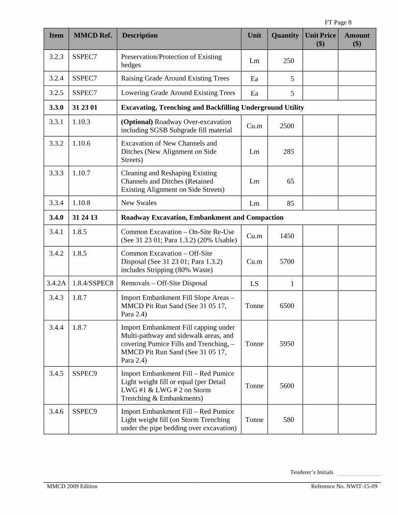
3.2.3 SSPEC7 Preservation/Protection of Existing hedges Lm 250
3.2.4 SSPEC7 Raising Grade Around Existing Trees Ea 5
3.2.5 SSPEC7 Lowering Grade Around Existing Trees Ea 5
3.3.0 31 23 01 Excavating, Trenching and Backfilling Underground Utility
3.3.1 1.10.3 (Optional) Roadway Over-excavation including SGSB Subgrade fill material Cu.m 2500
3.3.2 1.10.6 Excavation of New Channels and Ditches (New Alignment on Side Streets)
Lm 285
3.3.3 1.10.7 Cleaning and Reshaping Existing Channels and Ditches (Retained Existing Alignment on Side Streets)
Lm 65
3.3.4 1.10.8 New Swales Lm 85
3.4.0 31 24 13 Roadway Excavation, Embankment and Compaction
3.4.1 1.8.5 Common Excavation – On-Site Re-Use (See 31 23 01; Para 1.3.2) (20% Usable) Cu.m 1450
3.4.2 1.8.5 Common Excavation – Off-Site Disposal (See 31 23 01; Para 1.3.2) includes Stripping (80% Waste)
Cu.m 5700
3.4.2A 1.8.4/SSPEC8 Removals – Off-Site Disposal LS 1
3.4.3 1.8.7 Import Embankment Fill Slope Areas – MMCD Pit Run Sand (See 31 05 17, Para 2.4)
Tonne 6500
3.4.4 1.8.7 Import Embankment Fill capping under Multi-pathway and sidewalk areas, and covering Pumice Fills and Trenching, – MMCD Pit Run Sand (See 31 05 17, Para 2.4)
Tonne 5950
3.4.5 SSPEC9 Import Embankment Fill – Red Pumice Light weight fill or equal (per Detail LWG #1 & LWG # 2 on Storm Trenching & Embankments)
Tonne 5600
3.4.6 SSPEC9 Import Embankment Fill – Red Pumice Light weight fill (on Storm Trenching under the pipe bedding over excavation)
Tonne 580
Tenderer’s Initials MMCD 2009 Edition Reference No. NWIT-15-09
FT Page 9
Item MMCD Ref. Description Unit Quantity Unit Price ($)
Amount ($)
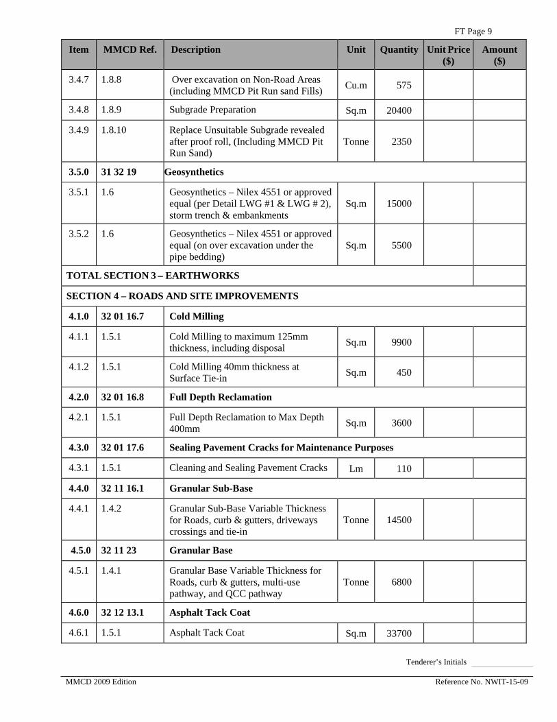
3.4.7 1.8.8 Over excavation on Non-Road Areas (including MMCD Pit Run sand Fills) Cu.m 575
3.4.8 1.8.9 Subgrade Preparation Sq.m 20400
3.4.9 1.8.10 Replace Unsuitable Subgrade revealed after proof roll, (Including MMCD Pit Run Sand)
Tonne 2350
3.5.0 31 32 19 Geosynthetics
3.5.1 1.6 Geosynthetics – Nilex 4551 or approved equal (per Detail LWG #1 & LWG # 2), storm trench & embankments
Sq.m 15000
3.5.2 1.6 Geosynthetics – Nilex 4551 or approved equal (on over excavation under the pipe bedding)
Sq.m 5500
TOTAL SECTION 3 – EARTHWORKS
SECTION 4 – ROADS AND SITE IMPROVEMENTS
4.1.0 32 01 16.7 Cold Milling
4.1.1 1.5.1 Cold Milling to maximum 125mm thickness, including disposal Sq.m 9900
4.1.2 1.5.1 Cold Milling 40mm thickness at Surface Tie-in Sq.m 450
4.2.0 32 01 16.8 Full Depth Reclamation
4.2.1 1.5.1 Full Depth Reclamation to Max Depth 400mm Sq.m 3600
4.3.0 32 01 17.6 Sealing Pavement Cracks for Maintenance Purposes
4.3.1 1.5.1 Cleaning and Sealing Pavement Cracks Lm 110
4.4.0 32 11 16.1 Granular Sub-Base
4.4.1 1.4.2 Granular Sub-Base Variable Thickness for Roads, curb & gutters, driveways crossings and tie-in
Tonne 14500
4.5.0 32 11 23 Granular Base
4.5.1 1.4.1 Granular Base Variable Thickness for Roads, curb & gutters, multi-use pathway, and QCC pathway
Tonne 6800
4.6.0 32 12 13.1 Asphalt Tack Coat
4.6.1 1.5.1 Asphalt Tack Coat Sq.m 33700
Tenderer’s Initials MMCD 2009 Edition Reference No. NWIT-15-09

FT Page 10
Item MMCD Ref. Description Unit Quantity Unit Price ($)
Amount ($)
4.7.0 32 12 13.2 Asphalt Prime
4.7.1 1.5.1 Asphalt Prime Sq.m 14700
4.8.0 32 12 16 Hot-Mix Asphalt Concrete Paving
4.8.1 1.5.1, 1.5.2 Asphalt Pavement – Lower Course # 1 Tonne 1800
4.8.2 1.5.1, 1.5.2 Asphalt Pavement – Upper Course # 1 Tonne 2800
4.8.3 1.5.1, 1.5.2 Asphalt Pavement levelling – Lower Course # 1 (assuming 60mm Average) Tonne 690
4.8.4 1.5.3 Asphalt Walk & Multi-use Pathway 50mm thick Upper Course #2, including ramps and QCC Pathway
Tonne 520
4.8.5 1.5.3 Asphalt Driveway (Tie-ins) 50mm thickness – Upper course # 2 Tonne 100
4.8.6 1.5.3 Asphalt Connector Walks to Pathway & Sidewalks, 50mm thickness – Upper course #2 (Granulars included on item 4.5.1)
Tonne 12
4.8.7 1.5.3 Asphalt Infill Strip 100mm c/w Granular Base Sq.m 65
4.8.8 1.5.6 Asphalt Pavement, Sidewalk, Driveway Hand –Placed 50mm thickness Sq.m 60
4.8.9 1.5.7 Saw Cut Asphalt or Concrete Pavements up to 200mm depth Lm 3200
4.9.0 Portland Cement Concrete Paving
4.9.1 SSPEC10 PCC 250mm Reinforced Concrete Bus Pad c/w additional base gravels, compaction and steel mesh
Sq.m 405
4.10.0 32 17 23 Painted Pavement Markings
4.10.1 1.5.3 Permanent Pavement Markings (Thermoplastic) – Including Special Crosswalks and Shared Pedestrians/Cyclist Stencils)
LS 1
4.11.0 32 21 13 Chain Link Fences & Gates
4.11.1 SSPEC11 Raise/ Relocate QCC Gate and Post to New Elevation LS 1
4.11.2 SSPEC12 1.4m high Bicyclist Handrail on Allan Block retaining wall (BC MoTI SP741-07.02)
Lm 220
Tenderer’s Initials MMCD 2009 Edition Reference No. NWIT-15-09
FT Page 11
Item MMCD Ref. Description Unit Quantity Unit Price ($)
Amount ($)
4.12.0 SSPEC13/SSPEC13A
Topsoil and Finish Grading
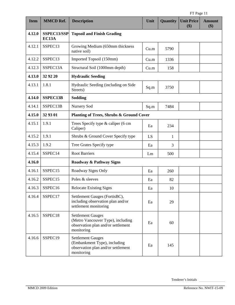
4.12.1 SSPEC13 Growing Medium (650mm thickness native soil) Cu.m 5790
4.12.2 SSPEC13 Imported Topsoil (150mm) Cu.m 1336
4.12.3 SSPEC13A Structural Soil (1000mm depth) Cu.m 158
4.13.0 32 92 20 Hydraulic Seeding
4.13.1 1.8.1 Hydraulic Seeding (including on Side Streets) Sq.m 3750
4.14.0 SSPEC13B Sodding
4.14.1 SSPEC13B Nursery Sod Sq.m 7484
4.15.0 32 93 01 Planting of Trees, Shrubs & Ground Cover
4.15.1 1.9.1 Trees Specify type & caliper (6 cm Caliper) Ea 234
4.15.2 1.9.1 Shrubs & Ground Cover Specify type LS 1
4.15.3 1.9.2 Tree Grates Specify type Ea 3
4.15.4 SSPEC14 Root Barriers Lm 500
4.16.0 Roadway & Pathway Signs
4.16.1 SSPEC15 Roadway Signs Only Ea 260
4.16.2 SSPEC15 Poles & sleeves Ea 82
4.16.3 SSPEC16 Relocate Existing Signs Ea 10
4.16.4 SSPEC17 Settlement Gauges (FortisBC), including observation plan and/or settlement monitoring
Ea 29
4.16.5 SSPEC18 Settlement Gauges (Metro Vancouver Type), including observation plan and/or settlement monitoring
Ea 60
4.16.6 SSPEC19 Settlement Gauges (Embankment Type), including observation plan and/or settlement monitoring
Ea 145
Tenderer’s Initials MMCD 2009 Edition Reference No. NWIT-15-09

FT Page 12
Item MMCD Ref. Description Unit Quantity Unit Price ($)
Amount ($)
4.17.0 SSPEC20 Removable Bollards (MMCD C12) Ea 40
4.18.0 SSPEC20 Removable Bollards (At Raised Intersections corners) Ea 32
4.19.0 SSPEC21 Site Furnishings
4.19.1 SSPEC21 Bench Backed c/w Concrete Pads Ea 5
4.19.2 SSPEC21 Bench Backed – Less Concrete Pads Ea 3
4.19.3 SSPEC21 Bike Racks Ea 4
4.20.0 SSPEC22 Irrigation System
4.20.1 SSPEC22 Irrigation System – Hampton to Derwent LS 1
TOTAL SECTION 4 – ROADS AND SITE IMPROVEMENTS
SECTION 5 – UTILITIES
5.1.0 33 01 30.1 CCTV Inspection Of Pipelines
5.1.1 1.6.2 CCTV Pipeline Inspection – Storm Sewers Lm 2246
5.2.0 33 11 01 Waterworks – (“PHASE 2”)
5.2.1 1.8.1, 1.8.2, SSPEC45
Watermain DI 150mm diameter – Cl 52 Wall Thickness All Depths, Typical MMCD G4 Imported Backfill, polyethylene encased with joint-wrapping
Lm 46
5.2.2 1.8.1, 1.8.2, SSPEC45, SSPEC47
Watermain DI 150mm diameter – Cl 52 Wall Thickness All Depths, LWG Backfill, polyethylene encased with joint-wrapping
Lm 107
5.2.3 1.8.1, 1.8.2, SSPEC45
Watermain DI 200mm diameter – Cl 52 Wall Thickness All Depths, Typical MMCD G4 Imported Backfill, polyethylene encased with joint-wrapping
Lm 32
5.2.4 1.8.1, 1.8.2, SSPEC45, SSPEC47
Watermain DI 200mm diameter – Cl 52 Wall Thickness All Depths, LWG Backfill, polyethylene encased with joint-wrapping
Lm 74
Tenderer’s Initials MMCD 2009 Edition Reference No. NWIT-15-09

FT Page 13
Item MMCD Ref. Description Unit Quantity Unit Price ($)
Amount ($)
5.2.5 1.8.1, 1.8.2 SSPEC45
Watermain DI 250mm diameter – Cl 52 Wall Thickness All Depths, Typical MMCD G4 Imported Backfill, polyethylene encased with joint-wrapping
Lm 432
5.2.6 1.8.1, 1.8.2, SSPEC45, SSPEC47
Watermain DI 250mm diameter – Cl 52 Wall Thickness All Depths, LWG Backfill, polyethylene encased with joint-wrapping
Lm 1008
5.2.7 1.8.1, 1.8.2, SSPEC45
Watermain DI 300mm diameter – Cl 52 Wall Thickness All Depths, Typical MMCD G4 Imported Backfill, polyethylene encased with joint-wrapping
Lm 13
5.2.8 1.8.3 In-line Gate Valves 150mm FL-FL, cover installation per CNW DWG SDW-1
Ea 1
5.2.9 1.8.3 In-line Gate Valves 150mm TYT-FL, cover installation per CNW DWG SDW-1
Ea 12
5.2.10 1.8.3 In-line Gate Valves 200mm TYT-FL, cover installation per CNW DWG SDW-1
Ea 10
5.2.11 1.8.3 In-line Gate Valves 200mm TYT-TYT, cover installation per CNW DWG SDW-1
Ea 1
5.2.12 1.8.3 In-line Gate Valves 250mm TYT-FL, cover installation per CNW DWG SDW-1
Ea 31
5.2.13 1.8.3 In-line Gate Valves 300mm TYT-FL, cover installation per CNW DWG SDW-1
Ea 2
5.2.14 1.8.3 Cross 250mm FL X 150mm FLX 250mm FLX 150mm FL Ductile Iron Pressure Rating 350 psi
Ea 4
5.2.15 1.8.3 Cross 250mm FL X 150mm FLX 250mm FLX 200mm FL Ductile Iron Pressure Rating 350 psi
Ea 2
Tenderer’s Initials MMCD 2009 Edition Reference No. NWIT-15-09
FT Page 14
Item MMCD Ref. Description Unit Quantity Unit Price ($)
Amount ($)
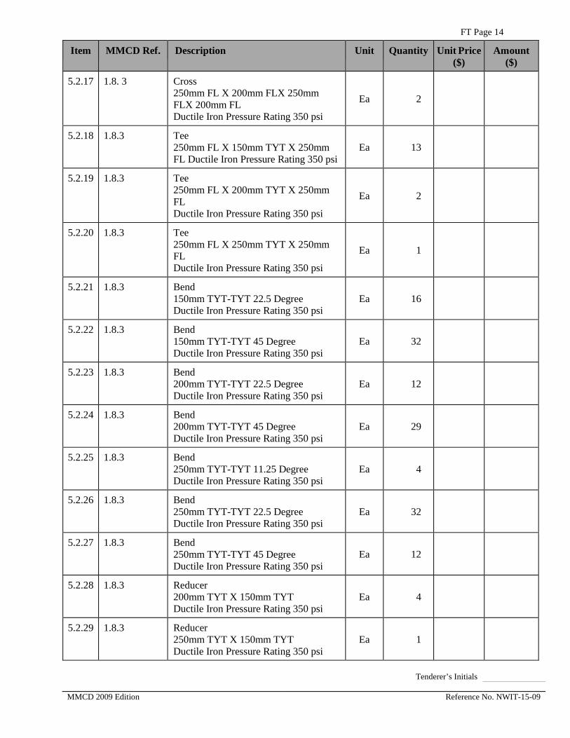
5.2.17 1.8. 3 Cross 250mm FL X 200mm FLX 250mm FLX 200mm FL Ductile Iron Pressure Rating 350 psi
Ea 2
5.2.18 1.8.3 Tee 250mm FL X 150mm TYT X 250mm FL Ductile Iron Pressure Rating 350 psi
Ea 13
5.2.19 1.8.3 Tee 250mm FL X 200mm TYT X 250mm FL Ductile Iron Pressure Rating 350 psi
Ea 2
5.2.20 1.8.3 Tee 250mm FL X 250mm TYT X 250mm FL Ductile Iron Pressure Rating 350 psi
Ea 1
5.2.21 1.8.3 Bend 150mm TYT-TYT 22.5 Degree Ductile Iron Pressure Rating 350 psi
Ea 16
5.2.22 1.8.3 Bend 150mm TYT-TYT 45 Degree Ductile Iron Pressure Rating 350 psi
Ea 32
5.2.23 1.8.3 Bend 200mm TYT-TYT 22.5 Degree Ductile Iron Pressure Rating 350 psi
Ea 12
5.2.24 1.8.3 Bend 200mm TYT-TYT 45 Degree Ductile Iron Pressure Rating 350 psi
Ea 29
5.2.25 1.8.3 Bend 250mm TYT-TYT 11.25 Degree Ductile Iron Pressure Rating 350 psi
Ea 4
5.2.26 1.8.3 Bend 250mm TYT-TYT 22.5 Degree Ductile Iron Pressure Rating 350 psi
Ea 32
5.2.27 1.8.3 Bend 250mm TYT-TYT 45 Degree Ductile Iron Pressure Rating 350 psi
Ea 12
5.2.28 1.8.3 Reducer 200mm TYT X 150mm TYT Ductile Iron Pressure Rating 350 psi
Ea 4
5.2.29 1.8.3 Reducer 250mm TYT X 150mm TYT Ductile Iron Pressure Rating 350 psi
Ea 1
Tenderer’s Initials MMCD 2009 Edition Reference No. NWIT-15-09

FT Page 15
Item MMCD Ref. Description Unit Quantity Unit Price ($)
Amount ($)
5.2.30 1.8.3 Cap 200mm diameter Ductile Iron Pressure Rating 350 psi
Ea 3
5.2.31 1.8.3 Cap 250mm diameter Ductile Iron Pressure Rating 350 psi
Ea 1
5.2.32 1.8.3 Cap 300mm diameter Ductile Iron Pressure Rating 350 psi
Ea 1
5.2.33 1.8.3 Mechanical Couplings 150mm DI x DI Ductile Iron Pressure Rating 350 psi
Ea 2
5.2.34 1.8.3 Mechanical Couplings 150mm DI x CI Ductile Iron Pressure Rating 350 psi
Ea 9
5.2.35 1.8.3 Mechanical Couplings 200mm DI x DI Ductile Iron Pressure Rating 350 psi
Ea 2
5.2.36 1.8.3 Mechanical Couplings 200mm DI x CI Ductile Iron Pressure Rating 350 psi
Ea 7
5.2.37 SSPEC24 Water Service Connections New 19mm diameter connect to new DI w/m
Ea 58
5.2.38 SSPEC24 Water Service Connections Cut & Transfer existing 19mm diameter to new DI w/m
Ea 5
5.2.39 SSPEC24 Water Service Connections Extend existing 19mm diameter to new DI W/M
Ea 1
5.2.40 SSPEC24 Water Service Connections Extend existing 50mm diameter to new DI W/M
Ea 1
5.2.41 SSPEC24 Water Service Connections Modify existing 19mm diameter at crossings of proposed utilities between Boyne St. and Pembina St. as shown on AMEC Drawing W-003
Ea 7
5.2.42 SSPEC24 Water Service Connections 50mm diameter Ea 1
5.2.43 1.8.4 Water Service Connections 150mm diameter Ea 2
Tenderer’s Initials MMCD 2009 Edition Reference No. NWIT-15-09

FT Page 16
Item MMCD Ref. Description Unit Quantity Unit Price ($)
Amount ($)
5.2.44 1.8.5 Test Point per Standard Drawing W5 Ea 22
5.2.45 1.8.14S Hydrant Assembly c/w Vertical Bends & Gate Valve per Standard Drawing W4
Ea 6
5.2.46 SSPEC25 Concrete Thrust Blocks Cu.m 105
5.2.47 1.8.13 Watermain Tie-In Pipe work by Contractor Ea 22
5.2.48 SSPEC9 Removal of existing watermains, fittings and appurtenances note
5.2.49 SSPEC26 Cutting, capping and abandonment of existing watermains and valves note
SSPEC46 Loading & Transport of suspect hazardous waste, Phase 2 – CNW Sta. -0+040 to 1+360
Cu.m 310.8
SSPEC46 Temporary onsite storage, Loading & Transport of suspect contaminated soil, Phase 2 – CNW Sta. –0+040 to 1+360
Cu.m 529.2
SSPEC46 Transport of contaminated groundwater LS 1
5.3.0 33 30 01 Sanitary Sewers
5.3.1 1.6.3 Sanitary Service Connection for # 843 Ewen Ave. 200mm dia. PVC DR 28 per Standard Drawings S7 and AMEC Drawing S-002
Ea 1
5.4.0 33 34 01 Sewage Forcemains – Jardine St to Woods St and along Wood St – “PHASE 2A”
5.4.1 1.8.2 Forcemain HDPE 200mm diameter, DR17, Pressure Rating 100 psi for depth of main 1.0m Imported Backfill – MMCD G4
Lm 458
5.4.1.1 SSPEC48 Forcemain Pipe 200mm diameter, DR17, Pressure Rating 100 psi for depth of main 1.0m Imported Backfill – LWG
Lm 642
5.4.2 1.8.3 Bend 200mm diameter 11.25 Degree Fused Bend Pressure Rating 100 psi
Ea 1
5.4.3 1.8.3 Bend 200mm diameter 45 Degree Fused Bend Pressure Rating 100 psi
Ea 22
Tenderer’s Initials MMCD 2009 Edition Reference No. NWIT-15-09

FT Page 17
Item MMCD Ref. Description Unit Quantity Unit Price ($)
Amount ($)
5.4.4 1.8.3 Bend 200mm diameter 90 Degree Fused Bend Pressure Rating 100 psi
Ea 22
5.4.5 1.8.3 WYE fitting 200mm diameter Pressure Rating 100 psi
Ea 2
5.4.6 1.8.3 Cap 200mm diameter Pressure Rating 100 psi
Ea 1
5.4.7 1.8.4 Gate Valves 200mm diameter
Ea 2
5.4.8 1.8.4 In-line Plug Valves c/w riser & valve box 200mm diameter per Contract Drawing S-004
Ea 5
5.4.9 SSPEC27 Flush Out Assembly (Supply and Installation of Light Weight Material and geotextile not included)
Ea 5
5.4.10 1.8.4 Temporary 150mm Riser Pipe & Cast Iron Valve Box per Contract Drawing S-001
Ea 1
5.4.11 1.8.5 Test Point Standard Drawing W5 Ea 8
5.4.12 1.8.10 Forcemain Tie-In to existing gate valve Ea 1
5.4.13 1.8.10 Forcemain Tie-In to existing manhole Ea 1
5.4.14 SSPEC46 Loading & Transport of suspect hazardous waste, Phase 2A SAN FM Cu.m. 428.3
5.4.15 SSPEC46 Temporary onsite storage, Loading & Transport of suspect hazardous waste, Phase 2A SAN FM Sta.
Cu.m 87.7
5.4.16 SSPEC46 Transport of contaminated groundwater LS 1
5.4.17 33 34 01 Sewage Forcemains – Wood St to Derwent Way – “PHASE 2B” OPTIONAL
5.4.18 1.8.2 Forcemain HDPE 200mm diameter, DR17, Pressure Rating 100 psi for depth of main 1.0m Imported Backfill – MMCD G4
Lm 154
Tenderer’s Initials MMCD 2009 Edition Reference No. NWIT-15-09

FT Page 18
Item MMCD Ref. Description Unit Quantity Unit Price ($)
Amount ($)
5.4.19 SSPEC48 Forcemain HDPE 200mm diameter, DR17, Pressure Rating 100 psi for depth of main 1.0m Imported Backfill – LWG
Lm 360
5.4.20 1.8.3 Bend 200mm diameter 11.25 Degree Fused Bend Pressure Rating 100 psi
Ea 8
5.4.21 1.8.3 Cap 200mm diameter Pressure Rating 100 psi
Ea 1
5.4.22 SSPEC27 Flush out Assembly (Supply and Installation of Light Weight Material and geotextile not included)
Ea 3
5.4.23 1.8.4 In-line Plug Valves c/w riser & valve box 200mm diameter per Contract Drawing S-004
Ea 3
5.4.24 1.8.4 Temporary 150mm Riser Pipe & Cast Iron Valve Box per Contract Drawing S-001
Ea 1
5.4.25 1.8.4 Test Point Standard Drawing W5 Ea 4
5.4.26 SSPEC46 Loading & Transport of suspect contaminated soil, Phase 2B Cu.m 256
5.4.27 SSPEC46 Temporary Storage, Loading & Transport of suspect contaminated soil, Phase 2B SAN FM
Cu.m. 52.4
5.4.28 SSPEC46 Transport of contaminated groundwater L.S. 1
5.5.0 33 40 01 Storm Sewers
5.5.1 SSPEC28 Regrading Existing Concrete Drainage Pipe 450mm diameter, depth of main 0-2m
Lm 25
5.5.2 1.6.3 Drainage Pipe PVC DR35 (Service Connection for Lot 843 Ewen Ave), 450mm diameter, depth 2-3m
Lm 7
5.5.3 SSPEC30 Drainage Pipe Concrete 1050mm diameter, ASTM C76M, Class III depth of main 2-3m (Supply and Installation of Light Weight Backfill and geotextile not included)
Lm 1.3
Tenderer’s Initials MMCD 2009 Edition Reference No. NWIT-15-09

FT Page 19
Item MMCD Ref. Description Unit Quantity Unit Price ($)
Amount ($)
5.5.4 SSPEC29 & SSPEC 30
Drainage Pipe HDPE or GRP 600mm diameter, depth of main 0-2m, in ditch infill areas (Supply and Installation of Light Weight Backfill and geotextile not included)
Lm 122
5.5.5 SSPEC29 & SSPEC 30
Drainage Pipe HDPE or GRP 600mm diameter, depth of main 0-2m, in non-ditch areas with Type B Trench. (Supply and Installation of geotextile not included)
Lm 22
5.5.6 SSPEC29 & SSPEC 30
Drainage Pipe HDPE or GRP 750mm diameter, depth of main 0-2m, in ditch infill areas (Supply and Installation of Light Weight Backfill and geotextile not included)
Lm 374
5.5.7 SSPEC29 & SSPEC 30
Drainage Pipe HDPE or GRP 750mm diameter, depth of main 0-2m, in non-ditch areas with Type A Trench
Lm 29
5.5.8 SSPEC29 & SSPEC 30
Drainage Pipe HDPE or GRP 750mm diameter, depth of main 0-2m, in non-ditch areas with Type B Trench. (Supply and Installation of geotextile not included)
Lm 43
5.5.9 SSPEC29 & SSPEC 30
Drainage Pipe HDPE or GRP 750mm diameter, depth of main 0-2m, in non-ditch areas with Type C Trench. (Supply and Installation of Light Weight Backfill and geotextile not included)
Lm 217
5.5.10 SSPEC29 & SSPEC 30
Drainage Pipe HDPE or GRP 900mm diameter, depth of main 0-2m, in ditch infill areas (Supply and Installation of Light Weight Backfill and geotextile not included)
Lm 364
5.5.11 SSPEC29 & SSPEC 30
Drainage Pipe HDPE or GRP 900mm diameter, depth of main 0-2m, in non-ditch areas with Type A Trench
Lm 58
Tenderer’s Initials MMCD 2009 Edition Reference No. NWIT-15-09

FT Page 20
Item MMCD Ref. Description Unit Quantity Unit Price ($)
Amount ($)
5.5.12 SSPEC29 & SSPEC 30
Drainage Pipe HDPE or GRP 900mm diameter, depth of main 0-2m, in non-ditch areas with Type B Trench. (Supply and Installation of geotextile not included)
Lm 87
5.5.13 SSPEC29 & SSPEC 30
Drainage Pipe HDPE or GRP 900mm diameter, depth of main 0-2m, in non-ditch areas with Type C Trench. (Supply and Installation of Light Weight Backfill and geotextile not included)
Lm 437
5.5.14 SSPEC29 SSPEC 30 & SSPEC31
Drainage Pipe HDPE or GRP 900mm diameter, depth of main 0-2m, fronting lot # 703 Ewen Ave. in non-ditch areas with Type B Trench. (Supply and Installation of geotextile not included)
Lm 50
5.5.15 SSPEC29 & SSPEC 30
Drainage Pipe HDPE or GRP 1050mm diameter, depth of main 0-2m, in ditch infill areas (Supply and Installation of Light Weight Backfill and geotextile not included)
Lm 235
5.5.16 SSPEC29 & SSPEC 30
Drainage Pipe HDPE or GRP 1050mm diameter, depth of main 0-2m, in non-ditch areas with Type A Trench
Lm 15
5.5.17 SSPEC29 & SSPEC 30
Drainage Pipe HDPE or GRP 1050mm diameter, depth of main 0-2m, in non-ditch areas with Type B Trench. (Supply and Installation of geotextile not included)
Lm 22
5.5.18 SSPEC29 & SSPEC 30
Drainage Pipe HDPE or GRP 1050mm diameter, depth of main 0-2m, in non-ditch areas with Type C Trench (Supply and Installation of Light Weight Backfill and geotextile not included)
Lm 110
Tenderer’s Initials MMCD 2009 Edition Reference No. NWIT-15-09

FT Page 21
Item MMCD Ref. Description Unit Quantity Unit Price ($)
Amount ($)
5.5.19 SSPEC29, SSPEC30 & SSPEC31
Drainage Pipe HDPE or GRP 1050mm diameter, depth of main 0-2m, in non-ditch areas, fronting lot # 703 Ewen Ave. in non-ditch areas with Type B Trench (Supply and Installation of geotextile not included)
Lm 31
5.5.20 1.6.3 Drainage Service Connections 150mm diameter PVC DR 28 or GRP per Standard Drawings S8 & Note 14 on AMEC Drawing D-001
Ea 83
5.5.21 1.6.4 Drainage Inspection Chamber item included in 33 44 01-1.5.2 Note
5.5.22 1.6.5 Catchbasin Lead 150mm diameter PVC DR 35 Lm 45
5.5.23 1.6.5 Catchbasin Lead 200mm diameter PVC DR 35 Lm 30
5.5.24 1.6.5 Lawn Drain Lead 150mm diameter PVC DR 35 Lm 32
5.5.25 1.6.9 Drainage Tie-In New Catchbasin or Lawn Drain into existing 150mm diameter CB lead or existing storm sewer
Ea 4
5.5.26 1.6.9 Drainage Tie-In 450mm diameter into existing 450mm diameter storm sewer
Ea 1
5.5.27 1.6.9 Drainage Tie-In 1050mm diameter into existing 1050mm diameter storm sewer
Ea 1
5.5.28 SSPEC32 Pro-Eco-Lite Headwall c/w Security Grid & Trash Gate for 600mm diameter pipe
Ea 19
5.5.29 SSPEC32 Pro-Eco-Lite Headwall c/w Security Grid & Trash Gate for 750mm diameter pipe
Ea 1
5.5.30 SSPEC32 Pro-Eco-Lite Headwall c/w Security Grid & Trash Gate for 900mm diameter pipe
Ea 1
5.5.31 SSPEC32 Pro-Eco-Lite Headwall c/w Security Grid & Trash Gate for 1050mm diameter pipe
Ea 1
Tenderer’s Initials MMCD 2009 Edition Reference No. NWIT-15-09

FT Page 22
Item MMCD Ref. Description Unit Quantity Unit Price ($)
Amount ($)
5.5.31.1 SSPEC33 End Cap for 600mm diameter pipe Ea 2
5.5.32 1.6.11 CCTV Pipeline Inspection Item included in 33 01 30.1 Note
5.5.33 SSPEC34 45 Degree Bends 600mm dia. HDPE or GRP – OPTIONAL Ea 44
5.5.34 SSPEC34 45 Degree Bends 750mm dia. HDPE or GRP Ea 4
5.5.35 SSPEC34 45 Degree Bends 900mm dia. HDPE or GRP Ea 4
5.5.36 SSPEC35 Drainage Pipe – Trenchless Installation 1050mm OD DR13.5 HDPE Lm 38
5.6.0 33 44 01 Manholes and Catchbasins
5.6.1 SSPEC36 Manhole base, lid, slab, cover and frame 1050mm diameter (Supply and Installation of Light Weight Material not included)
Ea 1
5.6.2 SSPEC36 Manhole base, lid, slab, cover and frame 1200mm diameter (Supply and Installation of Light Weight Material not included)
Ea 1
5.6.3 SSPEC36 Manhole base, lid, slab, cover and frame 1350mm diameter (Supply and Installation of Light Weight Material not included)
Ea 8
5.6.4 SSPEC36 Manhole base, lid, slab, cover and frame 1500mm diameter (Supply and Installation of Light Weight Material not included)
Ea 30
5.6.5 1.5.1.2 Manhole Riser and Tee Riser 1050mm diameter
Vertical Meters 4
5.6.6 1.5.1.2 Manhole Riser and Tee Riser 1200mm diameter
Vertical Meters 2
5.6.7 1.5.1.2 Manhole Riser and Tee Riser 1350mm diameter
Vertical Meters 15
5.6.8 1.5.1.2 Manhole Riser and Tee Riser 1500mm diameter
Vertical Meters 79
Tenderer’s Initials MMCD 2009 Edition Reference No. NWIT-15-09

FT Page 23
Item MMCD Ref. Description Unit Quantity Unit Price ($)
Amount ($)
5.6.9 1.5.1.4 Re-bench Existing Manhole Ea 1
5.6.10 1.5.1.6 Add Manhole to Existing System 1350mm diameter Ea 1
5.6.11 1.5.1.6 Add Manhole to Existing System 1500mm diameter Ea 2
5.6.12 SSPEC37 Catchbasin Top Inlet Standard DrawingS11 with “FISH" Symbol Ea 27
5.6.13 SSPEC38 Cast Iron Catchbasin per BC MoTI SP582-02.05 with “FISH" Symbol
Ea 5
5.6.14 1.5.2 Lawn Drain Top Inlet Standard Drawing S12 Type 2 Ea 17
5.6.15 1.5.2 Inspection Chamber Standard Drawing S9, S10 Ea 83
5.6.16 SSPEC9 Remove & Disposal of Existing Manholes, Catch basins, Lawn Drains, Cleanouts and Inspection Chambers
Note
TOTAL SECTION 5 – UTILITIES
SECTION 6 – STREET AND PATHWAY LIGHTING
6.1 SSPEC40 Street and Pathway Lighting (includes subgrade preparation for bases)
LS 1
TOTAL SECTION 6 – STREET AND PATHWAY LIGHTING
SECTION 7– TRAFFIC SIGNALS
7.1 SSPEC40 Traffic Signals (includes subgrade preparation for bases)
LS 1
TOTAL SECTION 7 – TRAFFIC SIGNALS
SECTION 8 – CITY OF NEW WESTMINSTER UNDERGROUND ELECTRIC DISTRIBUTION STRUCTURES (MATERIAL EXCEPT CONDUITS SUPPLIED BY CNW)
8.1 SSPEC41 (Scope 4.1)
Installation precast 12kV switchgear pads Ea 3
8.2 SSPEC41 (Scope 4.1)
Installation of 832 junction boxes Ea 8
8.3 SSPEC41 (Scope 4.1)
Installation of 1232 junction boxes Ea 7
Tenderer’s Initials MMCD 2009 Edition Reference No. NWIT-15-09
FT Page 24
Item MMCD Ref. Description Unit Quantity Unit Price ($)
Amount ($)
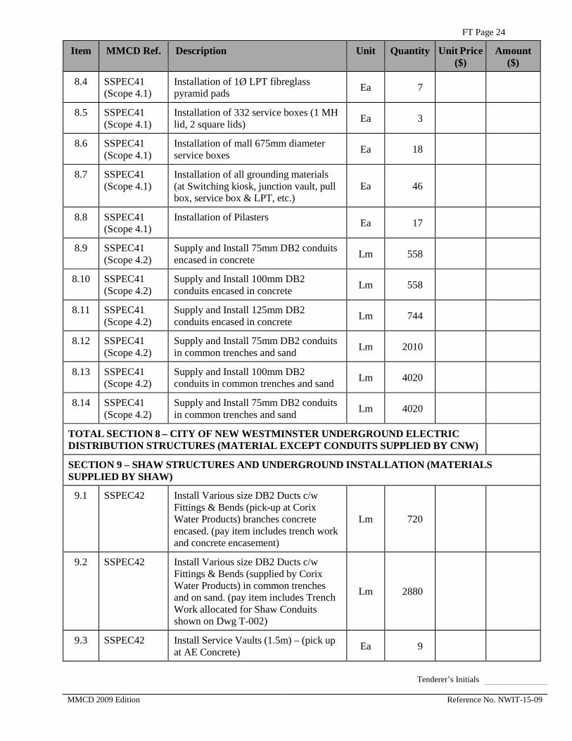
8.4 SSPEC41 (Scope 4.1)
Installation of 1Ø LPT fibreglass pyramid pads Ea 7
8.5 SSPEC41 (Scope 4.1)
Installation of 332 service boxes (1 MH lid, 2 square lids) Ea 3
8.6 SSPEC41 (Scope 4.1)
Installation of mall 675mm diameter service boxes Ea 18
8.7 SSPEC41 (Scope 4.1)
Installation of all grounding materials (at Switching kiosk, junction vault, pull box, service box & LPT, etc.)
Ea 46
8.8 SSPEC41 (Scope 4.1)
Installation of Pilasters Ea 17
8.9 SSPEC41 (Scope 4.2)
Supply and Install 75mm DB2 conduits encased in concrete Lm 558
8.10 SSPEC41 (Scope 4.2)
Supply and Install 100mm DB2 conduits encased in concrete Lm 558
8.11 SSPEC41 (Scope 4.2)
Supply and Install 125mm DB2 conduits encased in concrete Lm 744
8.12 SSPEC41 (Scope 4.2)
Supply and Install 75mm DB2 conduits in common trenches and sand Lm 2010
8.13 SSPEC41 (Scope 4.2)
Supply and Install 100mm DB2 conduits in common trenches and sand Lm 4020
8.14 SSPEC41 (Scope 4.2)
Supply and Install 75mm DB2 conduits in common trenches and sand Lm 4020
TOTAL SECTION 8 – CITY OF NEW WESTMINSTER UNDERGROUND ELECTRIC DISTRIBUTION STRUCTURES (MATERIAL EXCEPT CONDUITS SUPPLIED BY CNW)
SECTION 9 – SHAW STRUCTURES AND UNDERGROUND INSTALLATION (MATERIALS SUPPLIED BY SHAW)
9.1 SSPEC42 Install Various size DB2 Ducts c/w Fittings & Bends (pick-up at Corix Water Products) branches concrete encased. (pay item includes trench work and concrete encasement)
Lm 720
9.2 SSPEC42 Install Various size DB2 Ducts c/w Fittings & Bends (supplied by Corix Water Products) in common trenches and on sand. (pay item includes Trench Work allocated for Shaw Conduits shown on Dwg T-002)
Lm 2880
9.3 SSPEC42 Install Service Vaults (1.5m) – (pick up at AE Concrete) Ea 9
Tenderer’s Initials MMCD 2009 Edition Reference No. NWIT-15-09

FT Page 25
Item MMCD Ref. Description Unit Quantity Unit Price ($)
Amount ($)
9.4 SSPEC42 Install SB 5686 Service Boxes (Pull Boxes) – (pick up at AE Concrete) Ea 33
9.5 SSPEC42 Install #4828 Pedestals – (pick up at AE Concrete) Ea 6
TOTAL SECTION 9 – SHAW STRUCTURES AND UNDERGROUND INSTALLATION (MATERIALS SUPPLIED BY SHAW)
SECTION 10 – SPARE DUCTS UNDERGROUND INSTALLATION (SUPPLY AND INSTALL)
10.1 SSPEC43 Install 100mm DB2 Duct c/w bends & fittings if necessary in common trenches and on sand (pay item includes Trench Work allocated for Spare Conduits shown on Dwg T-002)
Lm 1920
TOTAL SECTION 10 – SPARE DUCTS UNDERGROUND INSTALLATION (SUPPLY AND INSTALL)
SECTION 11 – UTILITIES – WATERWORKS –CNW (“PHASE 3”) – OPTIONAL
11.0.0 33 11 01 Waterworks – Phase 3
11.1.1 1.8.1, 1.8.2, SSPEC45
Watermain DI 150mm diameter – Cl 52 Wall Thickness, All Depths, Typical MMCD G4 Imported Backfill, polyethylene encased with joint-wrapping
Lm 17
11.1.2 1.8.1, 1.8.2, SSPEC45, SSPEC47
Watermain DI 150mm diameter – Cl 52 Wall Thickness, All Depths, LWG Backfill, polyethylene encased with joint-wrapping
Lm 40
11.1.3 1.8.1, 1.8.2, SSPEC45
Watermain DI 200mm diameter – Cl 52 Wall Thickness, All Depths, Typical MMCD G4 Imported Backfill, polyethylene encased with joint-wrapping
Lm 4
11.1.4 1.8.1, 1.8.2, SSPEC45, SSPEC47
Watermain DI 200mm diameter – Cl 52 Wall Thickness, All Depths, LWG Backfill, polyethylene encased with joint-wrapping with joint-wrapping
Lm 9
11.1.5 1.8.1, 1.8.2, SSPEC45
Watermain DI 250mm diameter – Cl 52 Wall Thickness, All Depths, Typical MMCD G4 Imported Backfill, polyethylene encased with joint-wrapping
Lm 204
Tenderer’s Initials MMCD 2009 Edition Reference No. NWIT-15-09

FT Page 26
Item MMCD Ref. Description Unit Quantity Unit Price ($)
Amount ($)
11.1.6 1.8.1, 1.8.2, SSPEC45, SSPEC47
Watermain DI 250mm diameter – Cl 52 Wall Thickness, All Depths, LWG Backfill, polyethylene encased with joint-wrapping
Lm 500
11.1.7 1.8.1, 1.8.2, SSPEC45
Watermain DI 300mm diameter – Cl 52 Wall Thickness, All Depths, Typical MMCD G4 Imported Backfill, polyethylene encased with joint-wrapping
Lm 12
11.1.8 1.8.3 In-line Gate Valves 150mm TYT-FL, installation per CNW DWG SDW-1
Ea 4
11.1.9 1.8.3 In-line Gate Valves 200mm TYT-FL, installation per CNW DWG SDW-1
Ea 2
11.1.10 1.8.3 In-line Gate Valves 200mm TYT-TYT, installation per CNW DWG SDW-1
Ea 1
11.1.11 1.8.3 In-line Gate Valves 250mm TYT-FL, installation per CNW DWG SDW-1
Ea 14
11.1.12 1.8.3 In-line Gate Valves 300mm TYT-FL, installation per CNW DWG SDW-1
Ea 3
11.1.13 1.8.3 Cross 250mm FL X 150mm FLX 250mm FLX 150mm FL Ductile Iron Pressure Rating 350 psi
Ea 1
11.114 1.8.3 Tee 250mm FL X 150mm TYT X 250mm FL Ductile Iron Pressure Rating 350 psi
Ea 7
11.1.15 1.8.3 Tee 250mm FL X 200mm TYT X 250mm FL Ductile Iron Pressure Rating 350 psi
Ea 2
11.1.16 1.8.3 Tee 250mm FL X 250mm TYT X 250mm FL Ductile Iron Pressure Rating 350 psi
Ea 3
11.1.17 1.8.3 Tee 300mm FL X 250mm TYT X 300mm FL Ductile Iron Pressure Rating 350 psi
Ea 1
Tenderer’s Initials MMCD 2009 Edition Reference No. NWIT-15-09

FT Page 27
Item MMCD Ref. Description Unit Quantity Unit Price ($)
Amount ($)
11.1.17.1
1.8.3 Bend 150mm TYT-TYT 11.25 Degree Ductile Iron Pressure Rating 350 psi
Ea 1
11.1.18 1.8.3 Bend 150mm TYT-TYT 22.5 Degree Ductile Iron Pressure Rating 350 psi
Ea 3
11.1.19 1.8.3 Bend 150mm TYT-TYT 45 Degree Ductile Iron Pressure Rating 350 psi
Ea 2
11.1.20 1.8.3 Bend 200mm TYT-TYT 45 Degree Ductile Iron Pressure Rating 350 psi
Ea 2
11.1.21 1.8.3 Bend 250mm TYT-TYT 11.25 Degree Ductile Iron Pressure Rating 350 psi
Ea 5
11.1.22 1.8.3 Bend 250mm TYT-TYT 22.5 Degree Ductile Iron Pressure Rating 350 psi
Ea 0
11.1.23 1.8.3 Bend 250mm TYT-TYT 45 Degree Ductile Iron Pressure Rating 350 psi
Ea 11
11.1.24 1.8.3 Bend 300mm TYT-TYT 45 Degree Ductile Iron Pressure Rating 350 psi
Ea 1
11.1.25 1.8.3 Reducer 250mm TYT X 200mm TYT Ductile Iron Pressure Rating 350 psi
Ea 1
11.1.26 1.8.3 Cap 250mm diameter Ductile Iron Pressure Rating 350 psi
Ea 1
11.1.27 1.8.3 Cap 300mm diameter Ductile Iron Pressure Rating 350 psi
Ea 1
11.1.28 1.8.3 Mechanical Couplings 150mm DI x DI Ductile Iron Pressure Rating 350 psi
Ea 4
11.1.29 1.8.3 Mechanical Couplings 200mm DI x DI Ductile Iron Pressure Rating 350 psi
Ea 1
11.1.30 1.8.3 Mechanical Couplings 250mm DI x DI Ductile Iron Pressure Rating 350 psi
Ea 1
Tenderer’s Initials MMCD 2009 Edition Reference No. NWIT-15-09

FT Page 28
Item MMCD Ref. Description Unit Quantity Unit Price ($)
Amount ($)
11.1.31 SSPEC24 Water Service Connections New 19mm diameter connect to new DI w/m
Ea 31
11.1.32 SSPEC24 Water Service Connections Extend existing 19mm diameter to new DI W/M
Ea 4
11.1.33 SSPEC24 Water Service Connections Extend existing 50mm diameter to new DI W/M
Ea 2
11.1.34 1.8.5 Test Point per Standard Drawing W5 Ea 7
11.1.35 1.8.14S Hydrant Assembly c/w Vertical Bends & Gate Valve per Standard Drawing W4
Ea 3
11.1.36 SSPEC25 Concrete Thrust Blocks Cu.m 30
11.1.37 1.8.13 Watermain Tie-In Pipe work by Contractor Ea 7
11.1.38 SSPEC9 Removal of existing watermains, fittings and appurtenances note
11.1.39 SSPEC26 Cutting, capping and abandonment of existing watermains and valves note
SSPEC46 Loading & Transport of suspect hazardous waste, Phase 3 – CNW Sta. -0+040 to -0+750
Cu.m 353.6
Temporary onsite storage, Loading & Transport of suspect contaminated soil, Phase 3 – CNW Sta. –0+040 to –0+750
Cu.m 72.4
Transport of contaminated groundwater LS. 1
TOTAL SECTION 11 – UTILITIES – WATERWORKS –CNW (“PHASE 3”) – OPTIONAL
Tenderer’s Initials MMCD 2009 Edition Reference No. NWIT-15-09

FT Page 29
Item MV/MMCD Ref.
Description Unit Quantity Unit Price ($)
Amount ($)
SECTION 12 – METRO VANCOUVER QUE REPLACEMENT – “PHASE 2”
12.1.1 02507 SSPEC45, SSPEC47
Watermain DI 600mm main – LWG Trench, Pressure Class 350, with TR-Flex Joints, polyethylene encased with joint-wrapping and joint-bonding
Lm 918.6
12.1.2 02507 SSPEC45,
Watermain DI 600mm main – Typical MMCD G4 Trench, Pressure Class 350, with TR-Flex Joints, polyethylene encased with joint-wrapping and joint-bonding
Lm 393.7
12.1.3 11102 600mm Butterfly Valves c/w concrete chamber Ea 2
12.1.4 02507 Air Valve Assembly c/w concrete chamber per detail Ea 1
12.1.5 02507 Blowdown Assembly c/w concrete chamber per detail Ea 1
12.1.6 Temporary Tie-in (wet tap) to existing 450mm steel w/m at Jardine St per detail – (By Metro Vancouver)
Ea 1
12.1.7 Tie-in to existing 200mm steel w/m at Wood Street St per detail – (By Metro Vancouver)
Ea 1
12.1.8 Tie-in (wet tap) to existing 750mm steel w/m at Johnston Street per detail – (By Metro Vancouver)
Ea 1
12.1.9 SSPEC45 Electrical Isolation Kits (as per Reference Document – Attachment 8)
LS 1
12.1.10 SSPEC46 Loading & Transport of suspect hazardous waste, Phase 2 – MV Sta. -0+040 to 1+267
Cu.m 976
12.1.11 SSPEC46 Temporary onsite Storage, Loading & Transport of suspect contaminated soil, Phase 2 – MV Sta. -0+040 to 1+267
Cu.m. 200
Tenderer’s Initials MMCD 2009 Edition Reference No. NWIT-15-09

FT Page 30
Item MV/MMCD Ref.
Description Unit Quantity Unit Price ($)
Amount ($)
12.1.12 Transport of contaminated groundwater LS 1
12.1.13 02507 Mechanical Flowmeters c/w concrete chamber
Ea 1
TOTAL SECTION 12 METRO VANCOUVER QUE REPLACEMENT – “PHASE 2”
SECTION 13 – METRO VANCOUVER QUE REPLACEMENT – “PHASE 3” – OPTIONAL
13.1.1 02507 SSPEC45, SSPEC47
Watermain DI 600mm main LWG Trench, Pressure Class 350 with TR-Flex Joints, polyethylene encased with joint-wrapping and joint-bonding
Lm 489.71
13.1.2 02507 SSPEC45
Watermain DI 600mm main Typical MMCD G4 Trench, Pressure Class 350 with TR-Flex Joints, polyethylene encased with joint-wrapping and joint-bonding
Lm 209.87
13.1.3 11102 600mm Butterfly Valves c/w concrete chamber Ea 1
13.1.4 02507 Air Valve Assembly c/w concrete chamber Ea 1
13.1.5 02507 Blowdown Assembly c/w concrete chamber Ea 1
13.1.6 Tie-in (wet tap) to existing 660mm steel w/m at Boundary Rd – (By Metro Vancouver)
Ea 1
13.1.7 16124,16905, 16991, 16916, 16992,16010, 16060,16122
Magnetic Flowmeter & Chamber
LS 1
13.1.8 SSPEC45 Electrical Isolation Kits (as per Reference Document – Attachment 8
LS 1
13.1.9 SSPEC46 Loading & Transport of suspect hazardous waste, Phase 3 – MV Sta. -0+720 to –0+040
Cu.m 530.4
13.1.10 SSPEC46 Temporary onsite storage, Loading & Transport of suspect contaminated soil, Phase 3 – MV Sta. –0+720 to -0+040
Cu.m 108.6
Tenderer’s Initials MMCD 2009 Edition Reference No. NWIT-15-09
FT Page 31
Item MV/MMCD Ref.
Description Unit Quantity Unit Price ($)
Amount ($)
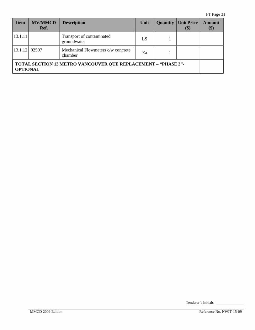
13.1.11 Transport of contaminated groundwater LS 1
13.1.12 02507 Mechanical Flowmeters c/w concrete chamber Ea 1
TOTAL SECTION 13 METRO VANCOUVER QUE REPLACEMENT – “PHASE 3”-OPTIONAL
Tenderer’s Initials MMCD 2009 Edition Reference No. NWIT-15-09

FT Page 32
FORM OF TENDER – Appendix 1
SCHEDULE OF QUANTITIES AND PRICES (See paragraph 5.3.1 of the Instructions to Tenderers – Part II)
(All prices and Quotations including the Contract Price shall include all Taxes, but shall not include GST. GST shall be shown separately.)
TENDER SUMMARY – PART I
ITEM DESCRIPTION TOTAL AMOUNT
SECTION 1 GENERAL $
SECTION 2 CONCRETE $
SECTION 3 EARTHWORKS $
SECTION 4 ROADS AND SITE IMPROVEMENTS $
SECTION 5 UTILITIES $
SECTION 6 STREET LIGHTING $
SECTION 7 TRAFFIC SIGNALS $
SECTION 8 CNW UNDERGROUND ELECTRICAL $
SECTION 9 SHAW – STRUCTURE AND DUCT INSTALLATION
$
SECTION 10 SPARE DUCTS SUPPLY AND INSTALLATION $
SECTION 12 METRO VANCOUVER QUE MAIN REPLACEMENT – “PHASE 2”)
$
SUB TOTAL $
5% GST $
TOTAL PRICE OF PART I $
Tenderer’s Initials MMCD 2009 Edition Reference No. NWIT-15-09

FT Page 33
TENDER SUMMARY – PART II – OPTIONAL
ITEM DESCRIPTION TOTAL AMOUNT
SECTION 5.4.10 UTILITIES – SANITARY FM PHASE 2B – OPTIONAL
$
SECTION 11 UTILITIES – PART 2 (WATERWORKS “PHASE 3”) – OPTIONAL
$
SECTION 13 METRO VANCOUVER QUE MAIN REPLACEMENT – “PHASE 3”) – OPTIONAL
$
SUB TOTAL $
5% GST $
TOTAL PRICE OF PART II $
SUMMARY:
PART I $
PART II $
TOTAL AMOUNT OF TENDER $
Tenderer’s Initials MMCD 2009 Edition Reference No. NWIT-15-09

FT Page 34
FORM OF TENDER – Appendix 2
PRELIMINARY CONSTRUCTION SCHEDULE (See paragraph 5.3.2 of the Instructions to Tenderers – Part II)
Indicate schedule with bar chart with major item descriptions and time
ACTIVITY CONSTRUCTION SCHEDULE (WEEKS)
1 2 3 4 5 6 7 8 9 10 11 12 13 14 15 16 17 18 19 20 21 22 23 24
Tenderer’s Initials MMCD 2009 Edition Reference No. NWIT-15-09

FT Page 35
FORM OF TENDER – Appendix 3
EXPERIENCE OF SUPERINTENDENT (See paragraph 5.3.3 of the Instructions to Tenderers – Part II)
Name: Years’ Experience:
Experience:
Date:
Project Name:
Responsibilities:
References:
Date:
Project Name:
Responsibilities:
References:
Date:
Project Name:
Responsibilities:
References:
Tenderer’s Initials MMCD 2009 Edition Reference No. NWIT-15-09

FT Page 36
FORM OF TENDER – Appendix 4
COMPARABLE WORK EXPERIENCE (See paragraph 5.3.4 of the Instructions to Tenderers – Part II)
PROJECT OWNER / CONTACT NAME PHONE and FAX
WORK DESCRIPTION
VALUE ($)
Owner / Contract
Phone Fax
Owner / Contract
Phone Fax
Owner / Contract
Phone Fax
Owner / Contract
Phone Fax
Owner / Contract
Phone Fax
Owner / Contract
Phone Fax
Tenderer’s Initials MMCD 2009 Edition Reference No. NWIT-15-09

FT Page 37
FORM OF TENDER – Appendix 5
SUBCONTRACTORS (See paragraph 5.3.5 of the Instructions to Tenderers – Part II)
TENDER ITEM
TRADE SUBCONTRACTOR NAME
PHONE NUMBER
PERCENTAGE OF WORK
Tenderer’s Initials MMCD 2009 Edition Reference No. NWIT-15-09
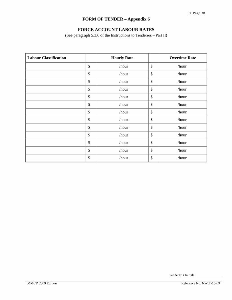
FT Page 38
FORM OF TENDER – Appendix 6
FORCE ACCOUNT LABOUR RATES (See paragraph 5.3.6 of the Instructions to Tenderers – Part II)
Labour Classification Hourly Rate Overtime Rate
$ /hour $ /hour
$ /hour $ /hour
$ /hour $ /hour
$ /hour $ /hour
$ /hour $ /hour
$ /hour $ /hour
$ /hour $ /hour
$ /hour $ /hour
$ /hour $ /hour
$ /hour $ /hour
$ /hour $ /hour
$ /hour $ /hour
$ /hour $ /hour
Tenderer’s Initials MMCD 2009 Edition Reference No. NWIT-15-09

FT Page 39
FORM OF TENDER – Appendix 7
DECLARATION – LIVING WAGE EMPLOYER (See paragraph 4.4 of the Instructions to Tenderers)
I, as a duly authorized signing officer of
Company:
Address
, confirm that all employees and sub‐contractors under our contract with the City as outlined below, are paid not less than the “Living Wage” as calculated by the Living Wage for Families Campaign.
I understand that this requirement extends only to those employees and sub‐contractors’ employees that perform work while on City premises and property for durations in excess of one continuous hour per occasion.
I understand that the City will conduct audits if and when notification of breach of this compliance is received by the City. I understand that in the event any breach of this declaration is found to be true, the City reserves the right to cancel its contract without penalty at any time once said authentication of the breach is made.
Contract Name:
Authorized Signatory: Dated:.
Tenderer’s Initials MMCD 2009 Edition Reference No. NWIT-15-09

AGREEMENT
• Agreement o Schedule 1 -- Schedule of Contract Documents o Schedule 2A -- List of Supplementary Conditions, Specifications &
Drawing o Schedule 2B -- List of Contract Drawings, Supplementary Detail Drawings
& Reference
MMCD 2009 Edition Reference No. NWIT-15-09

AGT Page 1 AGREEMENT
BETWEEN OWNER AND CONTRACTOR
(FOR USE WHEN UNIT PRICES FORM THE BASIS OF PAYMENT – TO BE USED ONLY WITH THE GENERAL CONDITIONS AND OTHER STANDARD DOCUMENTS OF THE UNIT PRICE MASTER MUNICIPAL CONSTRUCTION DOCUMENTS.)
BETWEEN OWNER AND CONTRACTOR
This agreement made in duplicate this
______ day of ___________, 2015
Contract: Ewen Avenue Reconstruction Project (Phase 2), City of New Westminster Watermain (Phase 2 & 3) and GVWD Queensborough Main No. 2 (Phase 2 & 3)
Reference No. NWIT-15-09
BETWEEN:
The Corporation of the City of New Westminster 511 Royal Avenue New Westminster, BC, V3L 1H9
(the “Owner”)
AND:
(NAME AND OFFICE ADDRESS OF CONTRACTOR)
(the “Contractor”)
MMCD 2009 Edition Reference No. NWIT-15-09

AGT PAGE 2
The Owner and the Contractor agree as follows:
Article 1 The Work Start / Completion Dates
1.1 The Contractor will perform all Work, provide all labour, equipment, and material, and do all things strictly as required by the Contract Documents.
1.2 The Contractor will commence the Work in accordance with the Notice to Proceed. The Contractor will proceed with the Work diligently, will perform the Work generally in accordance with the construction schedules as required by the Contract Documents and will achieve Substantial Performance of the Work on or before as stated on FT 2.2, subject to the provisions of the Contract Documents for adjustments to the Contract Time.
1.3 Time shall be of the essence of the Contract.
Article 2 Contract Documents
2.1 The “Contract Documents” consist of the documents listed or referred to in Schedule 1, entitled “Schedule of Contract Documents”, which is attached and forms a part of this Agreement, and includes any and all additional and amending documents issued in accordance with the provisions of the Contract Documents. All of the Contract Documents shall constitute the entire Contract between the Owner and the Contractor.
2.2 The Contract supersedes all prior negotiations, representations, or agreements, whether written or oral, and the Contract may be amended only in strict accordance with the provisions of the Contract Documents.
Article 3 Contract Price
3.1 The price for the Work (“Contract Price”) shall be the sum in Canadian dollars of the following:
3.1.1 the product of the actual quantities of the items of Work listed in the Schedule of Quantities and Prices which are incorporated into or made necessary by the Work and the unit prices listed in the Schedule of Quantities and Prices; plus
3.1.2 all lump sums, if any, as listed in the Schedule of Quantities and Prices, for items relating to or incorporated into the Work; plus
3.1.3 any adjustments, including any payments owing on account of Changes and agreed to Extra Work, approved in accordance with the provisions of the Contract Documents
3.2 The Contract Price shall be the entire compensation owing to the Contractor for the Work and this compensation shall cover and include all profit and all costs of supervision, labour, material, equipment, overhead, financing, and all other costs and expenses whatsoever incurred in performing the Work.
MMCD 2009 Edition Reference No. NWIT-15-09

AGT PAGE 3
Article 4 Payment
4.1 Subject to applicable legislation and the provisions of the Contract Documents, the Owner shall make payments to the Contractor.
4.2 If the Owner fails to make payments to the Contractor as they become due in accordance with the terms of the Contract Documents then interest calculated at 0% per annum over the prime commercial lending rate of the Royal Bank of Canada on such unpaid amounts shall also become due and payable until payment. Such interest shall be calculated and added to any unpaid amounts monthly.
Article 5 Rights and Remedies
5.1 The duties and obligations imposed by the Contract Documents and the rights and remedies available there under shall be in addition to and not a limitation of any duties, obligations, rights and remedies otherwise imposed or available by law.
5.2 Except as specifically set out in the Contract Documents, no action or failure to act by the Owner, Contract Administrator or Contractor shall constitute a waiver of any of the parties’ rights or duties afforded under the Contract, nor shall any such action or failure to act constitute an approval of or acquiescence in any breach under the Contract.
Article 6 Notices
6.1 Communications among the Owner, the Contract Administrator and the Contractor, including all written notices required by the Contract Documents, may be delivered by hand, or by fax, or by pre-paid registered mail to the addresses as set out below:
The Owner:
Corporation of the City of New Westminster 511 Royal Avenue New Westminster, BC V3L 1H9
Fax: Attention:
The Contractor:
Fax:
Attention:
MMCD 2009 Edition Reference No. NWIT-15-09

AGT PAGE 4
The Contract Administrator:
Fax:
Attention:
6.2 A communication or notice that is addressed as above shall be considered to have been received
6.2.1 immediately upon delivery, if delivered by hand; or
6.2.2 immediately upon transmission if sent by fax and received in hard copy; or
6.2.3 after 5 Days from date of posting if sent by registered mail.
6.3 The Owner or the Contractor, at any time, may change its address for notice by giving written notice to the other at the address then applicable. Similarly, if the Contract Administrator changes its address for notice then the Owner will give or cause to be given written notice to the Contractor.
6.4 The sender of a notice by fax assumes all risk that the fax is received in hard copy.
Article 7 General
7.1 This Contract shall be construed according to the laws of British Columbia.
7.2 The Contractor shall not, without the express written consent of the Owner, assign this Contract, or any portion of this Contract.
7.3 The headings included in the Contract Documents are for convenience only and do not form part of this Contract and will not be used to interpret, define, or limit the scope or intent of this Contract or any of the provisions of the Contract Documents.
7.4 A word in the Contract Documents in the singular includes the plural and, in each case, vice versa.
7.5 This agreement shall ensure to the benefit of and be binding upon the parties and their successors, executors, administrators and assigns.
IN WITNESS WHEREOF, the parties hereto have executed this Agreement the day and year first written above.
MMCD 2009 Edition Reference No. NWIT-15-09

AGT PAGE 5
Contractor:
(FULL LEGAL NAME OF CORPORATION, PARTNERSHIP OR INDIVIDUAL)
(AUTHORIZED SIGNATORY)
(AUTHORIZED SIGNATORY)
Owner:
Corporation of the City of New Westminster (FULL LEGAL NAME OF CORPORATION, PARTNERSHIP OR INDIVIDUAL)
(AUTHORIZED SIGNATORY)
Roy Moulder, SCMP, Purchasing Manager (AUTHORIZED SIGNATORY)
MMCD 2009 Edition Reference No. NWIT-15-09

AGT PAGE 6
Schedule 1 Schedule of Contract Documents
The following is an exact and complete list of the Contract Documents, as referred to in Article 2.1 of the Agreement.
NOTE: The documents noted with “*” are contained in the “Master Municipal Construction Documents – General Conditions, Specifications and Standard Detail Drawings”, edition dated 2009 Platinum. All sections of this publication are included in the Contract Documents.
Agreement, including all Schedules;
Supplementary General Conditions;
General Conditions*;
Supplementary Specifications;
Specifications*;
Supplementary Standard Detail Drawings;
Standard Detail Drawings*;
Executed Form of Tender, including all Appendices;
Contract Documents listed in Schedule 2A to the Agreement – “List of Supplementary Conditions, Specifications & Drawing”; Contract Documents listed in Schedule 2B to the Agreement – “List of Contract Drawings, Supplementary Detail Drawings & Reference”;
Instructions To Tenderers – Part I;
Instructions to Tenderers – Part II*;
The following Addenda:
(ADDENDA)
MMCD 2009 Edition Reference No. NWIT-15-09

AGT PAGE 7
Schedule 2A– List of Supplementary Conditions, Specifications & Drawings
SUPPLEMENTARY CONDITIONS, SPECIFICATIONS & DRAWINGS
Supplementary General Conditions SGC Page 1 – 8
General Conditions (MMCD, Platinum Edition) Not Reproduced
Supplementary Specifications – CNW SSPEC Page 1-55
Standard Specifications (MMCD, Platinum Edition) Not Reproduced
CNW Schedule C – Supplementary Specifications and Detail Drawings Not Reproduced
CNW Irrigation Standards and Specifications (2013) Not Reproduced
CNW Irrigation Standards and Specifications – 2 Wire Decoder Systems (2014) Not Reproduced
Standard Detail Drawings (MMCD, Platinum Edition) Not Reproduced
BC Hydro Underground Civil Manual (Recent) Not Reproduced
TAC MUTCD Recent Edition Not Reproduced
TAC Bikeway Traffic Control Guide for Canada Recent Edition Not Reproduced
BC MoTI Bicycle Traffic Control Guidelines Recent Edition Not Reproduced
BCNTA/BCSLA Standards Current Edition Not Reproduced
Greater Vancouver Water District Supplemental to City of New Westminster Tender No. NWIT-15-09 On FTP Site
MMCD 2009 Edition Reference No. NWIT-15-09

AGT PAGE 8
Schedule 2B – List of Contract Drawings, Supplementary Detail Drawings and Reference Drawings Contract Drawings:
TITLE DRAWING NO. REVISION NO. REVISION DATE
CIVIL DRAWINGS
Roadworks – Plan & Profile ED-I-001 B April 16, 2015
Roadworks – Plan & Profile R-001 B April 16, 2015
Roadworks – Plan & Profile R-002 B April 16, 2015
Roadworks – Plan & Profile R-003 B April 16, 2015
Roadworks – Plan & Profile R-004 B April 16, 2015
Roadworks – Plan & Profile R-005 B April 16, 2015
Roadworks – Plan & Plan R-006 B April 16, 2015
Roadworks – Plan & Plan R-007 B April 16, 2015
Roadworks – Plan & Profile R-008 B April 16, 2015
Drainage – Plan & Profile D-001 B April 16, 2015
Drainage – Plan & Profile D-002 B April 16, 2015
Drainage – Plan & Profile D-003 B April 16, 2015
Drainage – Plan & Profile D-004 B April 16, 2015
Drainage – Plan & Profile D-005 B April 16, 2015
Drainage – Plan & Profile D-006 B April 16, 2015
Drainage – Plan & Profile D-007 B April 16, 2015
Drainage – Plan & Profile D-008 B April 16, 2015
Drainage – Plan & Profile D-009 B April 16, 2015
Drainage – Plan & Profile D-010 B April 16, 2015
Drainage – Plan & Profile D-011 B April 16, 2015
Watermain – Plan & Profile W-001 C April 16, 2015
MMCD 2009 Edition Reference No. NWIT-15-09

AGT PAGE 9
Schedule 2B – List of Contract Drawings, Supplementary Detail Drawings and Reference Drawings Contract Drawings:
TITLE DRAWING NO. REVISION NO. REVISION DATE
Watermain – Plan & Profile W-002 C April 16, 2015
Watermain – Plan & Profile W-003 C April 16, 2015
Watermain – Plan & Profile W-004 C April 16, 2015
Watermain – Details W-005 C April 16, 2015
Watermain – Details W-006 C April 16, 2015
Watermain – Details W-007 C April 16, 2015
Watermain – Details W-008 C April 16, 2015
Watermain – Details W-009 C April 16, 2015
Watermain – Details W-010 C April 16, 2015
Watermain – Details W-011 C April 16, 2015
Watermain – Details W-012 C April 16, 2015
Sanitary – Plan & Profile S-001 B April 16, 2015
Sanitary – Plan & Profile S-002 B April 16, 2015
Sanitary – Plan & Profile S-003 B April 16, 2015
Sanitary – Plan & Profile S-004 B April 16, 2015
Sanitary – Plan & Profile S-005 B April 16, 2015
Geometrics and Laning G-001 B April 16, 2015
Geometrics and Laning G-002 B April 16, 2015
Geometrics and Laning G-003 B April 16, 2015
Spot Elevation SP-001 B April 16, 2015
Spot Elevation SP-001 B April 16, 2015
Typical Sections and Details T-001 B April 16, 2015
Typical Sections and Details T-002 B April 16, 2015
MMCD 2009 Edition Reference No. NWIT-15-09

AGT PAGE 10
Schedule 2B – List of Contract Drawings, Supplementary Detail Drawings and Reference Drawings Contract Drawings:
TITLE DRAWING NO. REVISION NO. REVISION DATE
Typical Sections and Details T-003 B April 16, 2015
Typical Sections and Details T-004 B April 16, 2015
Typical Sections and Details T-005 B April 16, 2015
Pavement Markings & Signing P-001 B April 16, 2015
Pavement Markings & Signing P-002 B April 16, 2015
Pavement Markings & Signing P-003 B April 16, 2015
Pavement Markings & Signing P-004 B April 16, 2015
Cross Sections XS-001 B April 16, 2015
Cross Sections XS-002 B April 16, 2015
Cross Sections XS-003 B April 16, 2015
Cross Sections XS-004 B April 16, 2015
Cross Sections XS-005 B April 16, 2015
Cross Sections XS-006 B April 16, 2015
Cross Sections XS-007 B April 16, 2015
Cross Sections XS-008 B April 16, 2015
Cross Sections XS-009 B April 16, 2015
Cross Sections XS-0010 B April 16, 2015
Cross Sections XS-0011 B April 16, 2015
Cross Sections XS-0012 B April 16, 2015
Cross Sections XS-0013 B April 16, 2015
LANDSCAPE
Cover J September 15, 2014
Key Plan L1.0 J September 15, 2014
MMCD 2009 Edition Reference No. NWIT-15-09

AGT PAGE 11
Schedule 2B – List of Contract Drawings, Supplementary Detail Drawings and Reference Drawings Contract Drawings:
TITLE DRAWING NO. REVISION NO. REVISION DATE
Site Plan L1.1 J September 15, 2014
Site Plan L1.2 J September 15, 2014
Site Plan L1.3 J September 15, 2014
Site Plan L1.4 J September 15, 2014
Materials Plan L2.1 J September 15, 2014
Materials Plan L2.2 J September 15, 2014
Materials Plan L2.3 J September 15, 2014
Materials Plan L2.4 J September 15, 2014
Layout Plan L3.1 J September 15, 2014
Layout Plan L3.2 J September 15, 2014
Layout Plan L3.3 J September 15, 2014
Layout Plan L3.4 J September 15, 2014
Planting Plan L4.1 J September 15, 2014
Planting Plan L4.2 J September 15, 2014
Planting Plan L4.3 J September 15, 2014
Planting Plan L4.4 J September 15, 2014
Notes & Schedules L5 J September 15, 2014
Details L6.1 J September 15, 2014
Details L6.2 J September 15, 2014
Details L6.3 J September 15, 2014
IRRIGATION
Irrigation Key Plan IRR-01 3 September 22, 2014
Zones 1 to 6 Irrigation Layout IRR-02 3 September 22, 2014
MMCD 2009 Edition Reference No. NWIT-15-09

AGT PAGE 12
Schedule 2B – List of Contract Drawings, Supplementary Detail Drawings and Reference Drawings Contract Drawings:
TITLE DRAWING NO. REVISION NO. REVISION DATE
Zones 7 to 12 Irrigation Layout IRR-03 3 September 22, 2014
Zones 13 to 16 Irrigation Layout IRR-04 3 September 22, 2014
Zones 17 to 19 Irrigation Layout IRR-05 3 September 22, 2014
Irrigation Details IRR-06 3 September 22, 2014
STREET LIGHTING AND TRAFFIC SIGNALS
Street Lighting: Ewen – Hampton to Derwent Way Sheet 1 of 8 1 April 14, 2015
Street Lighting: Ewen – Hampton to Derwent Way Sheet 2 of 8 1 April 14, 2015
Street Lighting: Ewen – Hampton to Derwent Way Sheet 1 of 8 1 April 14, 2015
Traffic Signal – Ewen at Howes Street Sheet 4 of 8 1 April 14, 2015
Traffic Signal – Ewen at Howes Street Sheet 5 of 8 1 April 14, 2015
Traffic Signal – Ewen at Derwent Way /Boyd Street Sheet 6 of 8 1 April 14, 2015
Traffic Signal – Ewen at Derwent Way /Boyd Street Sheet 7 of 8 1 April 14, 2015
QCC – Pedestrian Walkway Lighting Sheet 8 of 8 1 April 14, 2015
CNW – Underground Electrical
CNW – Ewen Avenue Undergrounding Civil Layout C677 Sh 1-4 R0 June 20, 2014
SHAW – Underground Electrical
SHAW – Ewen Avenue Structure and Duct Installation Details
RPN-152947 Sheet 1 of 4 Rev B August 10,2014
SHAW – Ewen Avenue Structure and Duct Installation Details
RPN-152947 Sheet 2 of 4 Rev B August 10,2014
SHAW – Ewen Avenue Structure and Duct Installation Details
RPN-152947 Sheet 3 of 4 Rev B August 10,2014
MMCD 2009 Edition Reference No. NWIT-15-09

AGT PAGE 13
Schedule 2B – List of Contract Drawings, Supplementary Detail Drawings and Reference Drawings Contract Drawings:
TITLE DRAWING NO. REVISION NO. REVISION DATE
SHAW – Ewen Avenue Structure and Duct Installation Details
RPN-152947 Sheet 4 of 4 Rev B August 10,2014
METRO VANCOUVER – PHASE 2 & 3 DRAWINGS
Site and Key Plan, Index to Drawings, Pipeline Profile
C-001 Rev E April 16,2015
Civil Standards Symbols and Abbreviations
X-001 Rev E April 16,2015
Phase 3 – Plan & Profile Sta -0+750 to -0+540
C-002 Rev E April 16,2015
Phase 3 – Plan & Profile Sta -0+540 to -0+300
C-003 Rev E April 16,2015
Phase 2/ Phase 3 – Plan & Profile ta -0+300 to 0+000
C-004 Rev E April 16,2015
Phase 2 – Plan & Profile Sta -0+000 to 0+280 C-005 Rev E April 16,2015
Phase 2 – Plan & Profile Sta -0+280 to 0+000
C-006 Rev E April 16,2015
Phase 2 – Plan & Profile Sta 0+000 to 0+550
C-007 Rev E April 16,2015
Phase 2 – Plan & Profile Sta 0+550 to 0+800
C-008 Rev E April 16,2015
Phase 2 – Plan & Profile Sta 0+800 to 1+090
C-009 Rev E April 16,2015
Phase 3 – Plan & Profile Sta 1+090 to 0+390
C-010 Rev E April 16,2015
Phase 3 – Plan & Profile Sta -0+300 to 0+000
C-011 Rev E April 16,2015
Phase 2 and Phase 3 Sections
C-012 Rev E April 16,2015
Phase 2 and Phase 3 Sections
C-013 Rev E April 16,2015
Phase 2 and Phase 3 Standard Details
C-014 Rev E April 16,2015
Phase 2 and Phase 3 Standard Details
C-015 Rev E April 16,2015
Phase 2 and Phase 3 Standard Details
C-016 Rev E April 16,2015
MMCD 2009 Edition Reference No. NWIT-15-09

AGT PAGE 14
Schedule 2B – List of Contract Drawings, Supplementary Detail Drawings and Reference Drawings Contract Drawings:
TITLE DRAWING NO. REVISION NO. REVISION DATE
Phase 2 and Phase 3 Standard Details
C-017 Rev E April 16,2015
Magnetic Flow Meter Installation – General Arrangement EI-478-01 A February 2011
Magnetic Flow Meter Installation – Grounding Details EI-478-02 A February 2011
Magnetic Flow Meter Installation – Notes EI-478-03 A February 2011
Layout Analog Junction Box WEPH-AJB-802
E-AJB-802-01 B April 2015
Loop Diagram Flow W-QUEM2-FIT-002 E-L-010-01 B April 2015
Schematic and Wiring Diagram Lighting Distribution Panel WEPH-LDP-801
E-LDP-801-01 B April 2015
Schematic and Wiring Diagram RTU A1:001 WEPH-RTU-803
E-RTU-803-01 C April 2015
Layout, Site Plan, Single Line Diagram & Details WEPH
E-001-01 C April 2015
Data Sheet – Electromagnetic Flow meter
W-QUEM2-FE-2 W-QUEM2-FIT-2 0 March 25, 2015
DAMAX CONSULTANTS-FORCE MAIN
FORCEMAIN DETAILS-NORTH END WOOD ST 5A F April 18, 2015
MMCD 2009 Edition Reference No. NWIT-15-09

AGT PAGE 15
Supplementary Detail Drawings
TITLE DWG. NO. REVISION DATE
SDD1 – Typical Settlement Gauge – Fortis BC
13-5933-SG-01 December 13, 2013 December 13,2013
SDD2 – Typical Settlement Gauge Detail (Metro Vancouver)
Document Code C-106 P4 January 4, 2008
SSD3 – Standard Type Settlement Gauge – Embankment Type
13-5933-SG-01 December 13, 2013 December 13,2013
SDD4 – BC MoTI Bicycle Sidewalk Fence
SP741-07.02 - October 1, 2008
SDD5 – BC MoTI Cast Iron Catchbasin
SP582-02.05 - November 1, 2011
SDD6 –Modified Spread Footing for Pole with Banner
Design Sketch IFC 0 July 31, 2014
Reference Drawings
Reference Drawings For Section 8 Form of Tender – BC Hydro Electric Distribution Standards Duct stub off details at URD, UD and feeder installations
ES54 H1-04
12kV Padmount Switchgear Precast Pad Installation details
ES54 E2-02.01
12KV Padmount Switchgear Precast Pad Installation details
ES54 E1-01.02
12KV Padmount Switchgear Precast Pad Installation details
ES54 E1-01.03
12KV Padmount Switchgear Precast Pad Installation details
ES54 E1-01.04
12KV Padmount Switchgear Precast Pad Installation details
ES54 E1-01.05
12KV and 25Kv Padmount Switchgear Precast Pad Installation details
ES54 E2-02.01 3
12KV and 25Kv Padmount Switchgear Precast Pad Installation details
ES54 E2-02.02 3
12KV and 25Kv Padmount ES54 E2-02.03 3
MMCD 2009 Edition Reference No. NWIT-15-09

AGT PAGE 16
Reference Drawings
Reference Drawings For Section 8 Form of Tender – BC Hydro Electric Distribution Standards Switchgear Precast Pad Installation details
Three Ø Junction Box 832 Precast Concrete Installation Details
ES54 D4–01.01
Three Ø Junction Box 832 Precast Concrete Installation Details
ES54 D4–01.02
Three Ø Junction Box 832 Precast Concrete Installation Details
ES54 D4–01.03
Three Ø Feeder Junction Box 1232 Precast Concrete Installation Details
ES54 D4–02.01
Three Ø Feeder Junction Box 1232 Precast Concrete Installation Details
ES54 D4–02.02
Three Ø Feeder Junction Box 1232 Precast Concrete Installation Details
ES54 D4–02.03
Single Phase Low Transformer Pyramid Pad (Fibreglass) Installation Details
ES54 F1–03.01
Single Phase Low Transformer Pyramid Pad (Fibreglass) Installation Details
ES54 F1–03.02
Single Phase Low Transformer Pyramid Pad (Fibreglass) Installation Details
ES54 F1–03.03
Single Phase Low Transformer Pyramid Pad (Fibreglass) Installation Details
ES54 F1–03.04
Service Box 332 Precast Concrete Installation details
ES54 B2–05.01
Service Box 332 Precast Concrete Installation details
ES54 B2–05.02
Service Box 332 Precast Concrete Installation details
ES54 B2–05.03
MMCD 2009 Edition Reference No. NWIT-15-09

AGT PAGE 17
Reference Drawings
Reference Drawings For Section 8 Form of Tender – BC Hydro Electric Distribution Standards Service Box 332 Precast Concrete Installation details
ES54 B2–05.04
Small lightweight service box 675mm diameter – Installation details
ES54 B3–01.01
Small lightweight service box 675mm diameter – Installation details
ES54 B3–01.02
Pilasters on wood poles Installation details
ES54 M1–01.01
Pilasters on wood poles Installation details
ES54 M1–01.02
Construction in Unstable Ground Transformer Pad Installation Pad Support in Unstable Ground
ES54 U4–04.01
Construction in Unstable Ground Transformer Pad Installation Pad Support in Unstable Ground
ES54 U4–04.02
Construction in Unstable Ground Transformer Pad Installation Pad Support in Unstable Ground
ES54 U4–04.03
Construction in Unstable Ground Transformer Pad Installation Pad Support in Unstable Ground
ES54 U4–04.04
Construction in Unstable Ground Transformer Pad Installation Pad Support in Unstable Ground
ES54 U4–04.05
Reference Drawings For Fortis BC
Fortis BC – Replacement at Ewen Avenue & Lawrence St
MCO 2800297263 Rev 0 Sheet 1 of 1
MMCD 2009 Edition Reference No. NWIT-15-09

SUPPLEMENTARY GENERAL CONDITIONS
• Supplementary General Conditions
MMCD 2009 Edition Reference No. NWIT-15-09

SGC PAGE-1
SUPPLEMENTARY GENERAL CONDITIONS
TABLE OF CONTENTS Page 1 Definitions 2 4 Contractor 2 4.1 Control of Work 2 4.3 Protection of Work, Property and the Public 2 4.6 Construction Schedule 4 4.17 Survey Layout and As-Constructed Information 5 4.19 City Industrial Health and Safety Program 5 9 Valuation of Changes and Extra Work – Quantity Variations 6 9.4 Quantity Variations 6 11 Concealed or Unknown Conditions 6 11.11 Definitions 6 13 Delays 6 13.8 Liquidated Damages for Late Completion 6 24 Insurance 6 24.1 Required Insurance 6 25 Maintenance Period 8 25.1 Correction of Defects 8 25.2 Commencement of Maintenance Period 8
MMCD 2009 Edition Reference No. NWIT-15-09

SGC PAGE-2
SUPPLEMENTARY GENERAL CONDITIONS
(TO BE READ WITH “GENERAL CONDITIONS” CONTAINED IN THE PLATINUM EDITION OF THE PUBLICATION “MASTER MUNICIPAL CONSTRUCTION DOCUMENTS” SPECIFIED IN “INSTRUCTIONS TO TENDERERS" IT - 2.2)
DEFINITIONS 1 1.79 “(amend clause X.XX as follows)” preceding a supplementary
clause means this clause modifies or provides additional information or restrictions to the referenced clause in the Master Municipal Construction Documents Platinum Edition, Volume II.
1.80 “(add new clause X.XX as follows)” preceding a supplementary clause means this clause provides additional requirements or information not found in the Master Municipal Construction Documents Platinum Edition, Volume II.
1.81 “(delete clause X.XX and replace as follows)” preceding a supplementary clause means this clause replaces the referenced clause in the Master Municipal Construction Documents Platinum Edition, Volume II in its entirety.
CONTRACTOR 4
Control of Work 4.1 4.1.3 (add clause 4.1.3 as follows) The Contractor shall take precautions to reduce nuisance caused
from mud or dust by clean-up, sweeping, sprinkling with water or other means as necessary to accomplish results satisfactory to the Contract Administrator. If the Contractor fails to maintain the site tidy or refuses to remove waste and debris as directed by the Contract Administrator, the Owner, at its own discretion, may proceed to clean the site, remove waste and debris from site, and deduct from any payment due the Contractor the cost of such cleaning or removing materials.
Protection of Work, Property and the Public
4.3 4.3.1 (Delete the following from the last paragraph of G.C.4.3.1 as follows) … except for damage, which, in the Performance of the Work, the Contractor could not reasonably avoid.
MMCD 2009 Edition Reference No. NWIT-15-09

SGC PAGE-3
4.3.4 (amend clause 4.3.4 as follows) (1) expose and determine conclusively the location in the field all underground utilities and structures whether or not indicated on the Contract Documents as being at the Place of the Work. The Contractor shall also be responsible to consult with all utility corporations that provide electricity, communication, gas or other utility services in the area of the Place of the Work, to locate in three dimensions all underground utilities for which they have records. The Contractor shall also locate in three dimensions any other utilities or underground structures that are reasonably apparent in an inspection of the Place of the Work. The Contractor shall provide Fortis BC with three weeks’ notice for relocation of any gas mains or services if it is required when crossing the gas lines.
4.3.6 (Delete 4.3.6 entirely) 4.3.7 (add new clause 4.3.7 as follows)
The Contractor shall locate, mark, and protect from damage or disturbance, any and all stakes, survey pins, monuments and markers at the Place of the Work. All survey stakes, survey pins, monuments, or markers that are damaged or disturbed shall be made good following construction by a registered BC Land Surveyor. Such repairs shall become part of the Work and shall be at the Contractor's expense.
4.3.8 (add new clause 4.3.8 as follows) Contractor to submit, fourteen (14) calendar days prior to the start of construction, a Traffic Management Plan (TMP) provided by a qualified traffic management company, and prepared in accordance with the “Traffic Control Manual for Work in Roadways”. Road closures will not be allowed without prior approval from the City of New Westminster. The cost of the TMP will be incidental to payment of work described in other sections. The Contractor shall ensure that single lane traffic movement is available in each direction at all times and shall minimize impact to on-street parking and pedestrian access to commercial and residential properties during working hours. The Contractor shall carry out the work such that access to commercial and residential properties is maintained at all times. The Contractor shall provide a minimum one week advance written notice to all property owners prior to construction, and shall also provide a minimum two (2) working days’ notice to individual property owners prior to commencing work affecting individual property access.
MMCD 2009 Edition Reference No. NWIT-15-09
SGC PAGE-4
The Contractor shall give due notice to local police and fire department prior to beginning construction and shall comply in all respects with their requirements. The Contractor shall comply with the requirements of the appropriate authority concerned with closure of streets or highways and shall post proper notices and/or signals, and provide necessary barriers, guards, lights, flagmen or watchmen as may be necessary for proper maintenance of traffic and protection of persons and property from injury or damage. All costs involved in respect of the above requirements will be deemed to be included in the Contract Price.
Where existing streets or roads are not available as detours, all traffic shall be permitted to pass through the Work with as little inconvenience and delay as possible unless otherwise provided or authorized. If half the street only is under improvement, the other half shall be conditioned and maintained as detour. Where construction is to be carried out on highways or properties other than those of the Owner it shall be the responsibility of the Contractor to familiarize himself with the requirements of the owners or controllers of these properties which pertain to traffic safety or control of the construction operation and to carry out his work in accordance with these requirements.
Construction Schedule
4.6 4.6.8 (add new clause 4.6.8 as follows) The hours of Work must not extend beyond 0700 h and 1900 h, inclusive, daily. The Contractor shall schedule their Work within these hours and will not be permitted to commence Work earlier than 0700 h and/or work later than 1900 h, except as authorized by the Contract Administrator.
4.6.9 (add new clause 4.6.9 as follows) The Contractor shall not schedule work that will require inspection beyond an eight-hour day without the Contract Administrator’s prior approval. Any extra cost incurred by the Owner for work done outside of normal office hours may be deducted from the Contractor’s monthly payments.
MMCD 2009 Edition Reference No. NWIT-15-09

SGC PAGE-5
4.6.10 (add new clause 4.6.10 as follows) On the infrequent occasion that the Contractor finds it necessary to work on Saturday, Sunday or Statutory Holiday, he shall obtain the Contract Administrator’s approval forty-eight (48) hours in advance. Work on Sundays or Statutory Holidays will also require the City’s approval, with a minimum two weeks’ notice. The Contractor shall also be charged a working day and may be charged the overtime inspection costs incurred by the Owner. Such costs shall be deducted from monthly progress payments.
Survey Layout and As-Constructed Information
4.17 4.17.1 (add new clause 4.17.1 as follows) The Contractor is responsible for all survey required for construction layout and for record drawings associated with this contract. The Contractor shall be responsible for recording of all field survey information pertaining to the as-constructed drawings. The Contractor shall provide, at no charge, a completed set of legible, marked-up as-constructed prints to the Contract Administrator on completion of the Work. The Contractor shall provide any additional information as requested to enable the Contract Administrator to prepare and submit as-constructed record drawings to the Municipality or the Owner for their records.
City Industrial Health and Safety Program
4.19 4.19 (add new clause 4.19 as follows) 4.19.1 All Contractors working for the City of New Westminster are required to be aware of the City’s Industrial Health and Safety Program. It is the Contractor’s responsibility to perform the job in compliance with the City’s safety standards. The Contractor is responsible for the compliance of all employees for whom he is primarily responsible, with all WorkSafe BC Industrial Health and Safety Regulations, as well as all other applicable Regulations.
4.19.2 As a Contractor/Subcontractor signing a contract with the City, you are agreeing that your Company, Management Staff, Supervisory Staff and workers will comply with our Industrial Health and Safety Program. This is binding while you are on any City work site.
4.19.3 An infraction not immediately corrected, as directed by the contracting City Department, will result in the Contractor / Subcontractor being advised of a breach of contract and advised of action, which will be taken. It must be definitely established that all workers on the job, including all Subcontractor’s employees, are informed of our safety program.
Copies of the City’s Industrial Health and Safety Program may be obtained at Engineering Operations, 901 – 1st Street.
MMCD 2009 Edition Reference No. NWIT-15-09

SGC PAGE-6
Valuation of Changes and Extra Work – Quantity Variations
9 9.4.1 (delete clause 9.4.1 and replace as follows) The Contractor shall hold firm all unit prices submitted in the Schedule of Quantities and Prices regardless of the increase or decrease in quantities.
Concealed or Unknown Conditions
11 11.1.1 (delete 11.1.1 and substitute with the following) A “Concealed or Unknown Conditions” is Hazardous Materials not disclosed in the Contract Documents.
11.1.2 (add the clause 11.1.2 as follows) The Contractor bears the risk and liability for utilities and subsurface soil conditions. The Contractor acknowledges that it has not relied on accuracy of any information provided by the Owner in evaluating these risks. The Contractor acknowledges that it has full responsibility for locating utilities and has conducted its own investigation and has made allowance in the Contract Price for these risks.
DELAYS 13
Liquidated Damages for Late Completion
13.8 13.8.1 a) (delete clause 13.8.1 a) and replace as follows) As a genuine pre-estimate of the Owner’s increased costs for the Contract Administrator and the Owner’s own staff caused by such delay an amount of $1,000.00 per day or pro rata portion for each Day that actual Substantial Performance is achieved after the Substantial Performance Milestone Date; plus
INSURANCE 24
Required Insurance 24.1 24.1 (amend 24.1 as follows) In addition to the MMCD insurance requirements, the Contractor shall also comply with the following requirements, which will take precedence. 24.1.1 The Contractor shall insure and keep insured while this Contract is in force, with such companies and on such forms as are acceptable to the Owner, at the Contractor’s expense. Commercial General Liability Insurance covering premises and operations liability; Contractor’s Contingency Liability with respect to the operations of Subcontractor’s Completed Operations Liability, Contractual Liability and Non-Owned Automobile Liability Insurance.
24.1.1(1) (replace 24.1.1(1) with the following) The limits of liability for Personal Injury and Property Damage combined shall be for not less than $5,000,000 each occurrence.
MMCD 2009 Edition Reference No. NWIT-15-09

SGC PAGE-7
24.1.1(2) (add to 24.1.1(2) as follows) The following shall be named as additional insured on the Contract: • Corporation of the City of New Westminster
• ………………………………………………….
(Full name of Contract Administrator)
• ………………………………………………….
(Full name of Contract Administrator sub consultant)
• ………………………………………………….
(Full name of Contract Administrator sub consultant)
• ………………………………………………….
(Full name of Contract Administrator sub consultant)
• All subcontractors A Cross Liability Clause shall be made part of the Commercial General Liability Insurance.
24.1.7 (add new 24.1.7 as follows) All policies shall provide that they cannot be cancelled, lapsed, or materially changed without at least thirty (30) days’ notice to the Owner by Registered Mail. Prior to commencement of any work hereunder, the Contractor shall file with the Owner a certificate of insurance for each policy required. All such insurance shall be maintained until final completion of the work including the making good of faulty work or materials, except that coverage for completed operations liability shall in any event be maintained for twelve (12) months from date of final acceptance. Should the Contractor neglect to obtain and/or maintain insurance as aforesaid, or deliver such policy or policies to the Owner, then the Owner shall obtain and/or maintain such insurance and the Contractor hereby appoints the Owner its true and lawful attorney to do all things necessary for this purpose. All monies expended by the Owner for Insurance premiums under the provisions of this clause shall be charged to the Contractor.
MMCD 2009 Edition Reference No. NWIT-15-09

SGC PAGE-8
Maintenance Period Correction of Defects
25
25.1 25.1.4 (add clause 25.1.4 as follows) The Owner is authorized to make repairs to defects or deficiencies if, ten days after giving written notice, the Contractor has failed to make or undertake with due diligence the required repairs. However, in the case of emergency where, in the opinion of the Owner, delay is not reasonable, repairs may be made without notice being sent to the Contractor. All expenses incurred by the Owner in connection with repairs made pursuant to GC 25 shall be paid by the Contractor and may be deducted from the Maintenance Security, or other holdbacks. The Contractor shall promptly pay any shortfall.
Commencement of Maintenance Period
25.2 25.2.2 (amend clause 25.2.2 as follows) All warranties under this Contract commence from the date of Substantial Performance of the Contract, regardless of whether any Subcontractor achieves Substantial Performance of its Subcontract prior to Substantial Performance of the Contract.
MMCD 2009 Edition Reference No. NWIT-15-09

SUPPLEMENTARY SPECIFICATIONS
• Supplementary Specifications
MMCD 2009 Edition Reference No. NWIT-15-09

SSPEC PAGE-1
SUPPLEMENTARY SPECIFICATIONS
TABLE OF CONTENTS Page SSPEC1 Project Record Documents 3 SSPEC2 Restoration Work and Property Impacts on Private Property 3 SSPEC2A Restoration of Park @ Lot 703 4 SSPEC3 Concrete Curb Cuts (for Drainage) 4 SSPEC4 Concrete Walks, Curbs And Gutters 4 SSPEC5 Not Used 5 SSPEC6 Allan Block Wall & Stairs 5 SSPEC7 Tree and Shrub Protection/Preservation 5 SSPEC8 Removals and Offsite Disposal 5 SSPEC9 Red Pumice Lightweight Fill 6 SSPEC10 Portland Cement Concrete Paving 6 SSPEC11 Relocate Queensborough Community Centre (OCC) sign, gate
and post 7
SSPEC12 Bicyclist handrail 7 SSPEC13 Soil Preparation and Placement (Top Soil and Finish Grading) 7 SSPEC13A Structural Soil 7 SSPEC13B Sodding 8 SSPEC14 Root Barriers 8 SSPEC15 Roadway and Pathway Signs and Sign Posts 8 SSPEC16 Relocate existing Road signs 8 SSPEC17 Settlement Gauges – Fortis BC Type 8 SSPEC18 Settlement Gauges – Metro Vancouver Type 9 SSPEC19 Settlement Gauges – Embankment Type 9 SSPEC20 Removable Bollards 10 SSPEC21 Site Furnishings 10 SSPEC22 Irrigation Systems 10 SSPEC23 Not Use 11 SSPEC24 Waterworks – Water Service Connections 11 SSPEC25 Waterworks – Concrete Thrust Blocks 11 SSPEC26 Waterworks – Cutting, Capping And Abandonment Of Existing
Watermains and Valves 12
SSPEC27 Sewage Forcemains – Flush Out Assemblies 12 SSPEC28 Storm Sewers – Regrading Existing Concrete Pipe 13 SSPEC29 Storm Sewers – Glassfibre Reinforced Plastic (GRP) Pipes 13 SSPEC30 Storm Sewers – Measurement and Payment 14 SSPEC31 Storm Sewers – Storm Pipes Fronting Lot #703 Ewen Avenue 15
MMCD 2009 Edition Reference No. NWIT-15-09
SSPEC PAGE-2
TABLE OF CONTENTS Page SSPEC32 Storm Sewers – Pro-Eco-Lite Headwalls 15 SSPEC33 Storm Sewers – End Caps 15 SSPEC34 Storm Sewers – Bends 16 SSPEC35 Storm Sewers – Drainage Pipe – Trenchless Installation HDPE
DR13.5 105mm OD 16
SSPEC36 Manholes and Catchbasins 17 SSPEC37 Manholes and Catchbasins – Catchbasins Top Inlet with “FISH”
symbol 18
SSPEC38 Manholes and Catchbasins – Cast Iron Catch Basins with “FISH” symbol
18
SSPEC39 Concrete Walks, Curb And Gutter – Grade Adjustments To Existing Utilities
18
SSPEC40 Street Lighting and Traffic Signal Works 19 SSPEC41 City of New Westminster Specifications for Underground Electric
Distribution Structures 21
SSPEC42 Shaw Structure and Underground Duct Installation Details 39 SSPEC43 Spare Ducts 43 SSPEC44 BCNTA/BCSLA Standards Current Edition 44 SSPEC45 Cathodic Protection 44 SSPEC46 Contaminated Material Management 47 SSPEC47 Waterworks – Watermain for City of New Westminster and Metro
Vancouver 55
SSPEC48 Sewage Forcemain – Sanitary Forcemains 55
MMCD 2009 Edition Reference No. NWIT-15-09

SSPEC PAGE-3
SUPPLEMENTARY SPECIFICATIONS
SSPEC1 Must be read in conjunction in the Specifications contained in MMCD Platinum 2009 Section 01 33 01 – Project Record Documents (add the clause 1.8.2 as follows) (1) Payment for all work performed under MMCD – Specifications,
Section 01 33 01 will be paid after issuance of Certificate of Substantial Performance and after receipt of all record drawings and as constructed information, all to the satisfaction of the Contract Administrator which consists of but is not limited to the following:
(2) Maintain record drawings and accurately record changes from Contract Documents caused by site conditions and changes ordered by the Owner.
(3) Mark all record drawing changes in red ink. (4) Record and submit the following information:
(a) Horizontal and vertical location of underground services and utilities including watermains, sanitary sewers or forcemains, storm sewers, CNW underground electrical, Shaw underground electrical, and the spare conduits, and supportive survey information in ASCII text files.
(b) Field changes of dimensions and details.
(c) Changes made by Change Order or Site Instruction/Field Order.
At completion of the project and prior to final inspection submit completed “record" drawings to the City of New Westminster.
SSPEC 2 Restoration Work and Property Impacts on Private Property Measurement of Payment This clause is applicable to all Properties (except Lot #703). At the time of tender some of the restoration works on private properties and property impacts adjacent to private properties have not been finalized.
The Contractor is advised that no work shall proceed until a unit price for the work has been negotiated and agreed to by the City.
MMCD 2009 Edition Reference No. NWIT-15-09
SSPEC PAGE-4
SSPEC2A Restoration of Park @ Lot 703 Measurement of Payment This clause is only applicable to Lot #703. At the time of tender some of the restoration works on this private property and property impacts adjacent to this private property have not been finalized.
The Contractor is advised that no unidentified work shall proceed until a unit price for the work has been negotiated and agreed to by the City.
SSPEC3 Concrete Curb Cuts (for Drainage) Measurement and Payment Measurement and payment will be in accordance with Schedule of Quantities and prices and shall include all labour and materials required to supply and install concrete, base gravels, sub-base gravels, compaction, curing, finishing and all incidental work such as the gravel apron, required for the installation.
SSPEC4 Must be read in conjunction in the Specifications contained in MMCD Platinum 2009 Section 03 30 20 – Concrete Walks, Curbs And Gutters Concrete Driveway crossings (delete 1.4.6 and substitute with the following) Payment for concrete driveway crossings including granular base and subbase as shown on drawing C7 will be made by square area for each specified thickness and finish.
Must be read in conjunction in the Specifications contained in MMCD Platinum 2009 Section 03 30 20 – Concrete Walks, Curbs And Gutters Measurement and Payment Concrete Driveway Tie-in (add the clause 1.4.10 as follows) Payment for the non-reinforced concrete driveway tie-in will be made by the square meter for each specified thickness and finish. (exposed aggregate or broom finish). Payment will be based on actual constructed measurements in the field and includes base gravels up to a depth of 250mm. Excavation and Backfilling will be paid under the appropriate pay items in Section 31 23 01 – Excavation, trenching and backfilling.
MMCD 2009 Edition Reference No. NWIT-15-09

SSPEC PAGE-5
SSPEC5 Not Used.
SSPEC6 Allan Block Wall & Stairs Measurement and Payment Payment for the supply and install of Allan Block wall will be by square meter including all labour and materials required to complete the work as shown on the contract drawings. Measurement for payment for wall face shall be measured from the underside of the bottom row of blocks to the underside of the cap block, multiplied by the length of the wall. Construct retaining walls in accordance with requirements of system manufacturer, including a drainage system behind the wall.
Payment for the Allan Block stairs will be by riser-per-linear meter and includes the supply and installation of allan block risers and treads, well-graded granular rock and perforated pipe where required as shown on the contract drawings. Excavation will be paid under the appropriate pay items in MMCD Platinum 2009 Section 31 23 01 – Excavation, trenching and backfilling.
SSPEC7 Must be read in conjunction in the Specifications contained in BCNTA/BCSLA Standards Current Edition Section 32 01 91 – Tree and Shrub Protection/Preservation Measurement and Payment 1. Payment for Tree and Shrub protection/preservation and graded
changes items includes all applicable work described in this Section and will cover an area of shrubs or individual trees to be attended to as shown on contract drawings or as directed by the Contract Administrator.
2. Payment for Hedge protection/preservation will be made by linear meter and includes all applicable work described in this section and will cover the length of hedges to be attended to as shown on the contract drawings or as directed by the Contract Administrator.
SSPEC8 Removals and Offsite Disposal Measurement and payment Payment for removals and off-site disposal will be as a lump sum and includes items that have been excluded from the payment under section 31 24 13. This payment covers removal of existing drainage structures, water, and sanitary features or structures (as applicable), street lights traffic signals and structural features or structures as required for the execution of work as well as removals shown on the contract drawings.
MMCD 2009 Edition Reference No. NWIT-15-09

SSPEC PAGE-6
SSPEC9 Red Pumice Lightweight Fill Lightweight Granular Fill (LWG) Lightweight Granular fill is to be used within select road embankment fill areas as shown on the contract drawings.
Lightweight Granular Fill to comprise of vesicular basalt nominal 25mm to 50mm uniformly graded material with less than 3% passing the #4.75 sieve. A 15 kg sample of proposed LWG materials is to be provided to the contract administrator for review and approval at least one week prior to onsite use.
The lightweight aggregate is to be wrapped in AASHTO M288 Class 2 survivability non-woven filter fabric (Nilex 4551 or approved equivalent).
LWG should be placed in maximum 300mm thick loose lifts. Compaction should be carried out using 3 passes of a 500 lb plate compactor. Excessive compactive effort/equipment that results in material break-down is to be avoided.
Measurement and Payment Imported Lightweight Fills including supply, placement and compaction will be measured in tonnes based on weight tickets provided to the Engineer as loads are delivered. Quantities actually placed and compacted will also to be verified by the Engineer.
SSPEC10 Must be read in conjunction in the Specifications contained in MMCD Platinum 2009 Section 32 13 13 Portland Cement Concrete Paving Measurement and Payment Reinforced concrete Bus Stop Slab (add the clause 1.4.6 as follows) Payment for the reinforced concrete Bus Stop slab will be by the square metre installed to specifications as measured in the field. This price shall include all labour and materials to complete the work shown on the contract drawings including, but not limited to the preparation, additional base gravels and compaction, supply and installation of concrete, steel mesh, construction and expansion joints, curing, finishing and all incidental work required for installation of the new bus pad, including saw-cutting existing pavement as required. Excavation will be paid under the appropriate pay items in Section 31 23 01 – Excavation, trenching and backfilling.
MMCD 2009 Edition Reference No. NWIT-15-09

SSPEC PAGE-7
SSPEC11 Relocate Queensborough Community Centre (QCC) sign, gate and post Measurement and Payment Payment for relocating the sign, gate and post will be by lump sum price tendered and will include the supply of all necessary components, excavation, and materials necessary to complete the work. Also, included in the price will be the transportation for safekeeping on site as directed by Contract administrator.
Contractor to ensure the preservation of the existing condition during relocation/installation to the new location. The Contractor will be responsible for the damage and replacement of the item during the relocation and installation process.
SSPEC12 Bicyclist handrail Measurement and Payment Fencing will be measured by the LINEAL METRE. Measurements will be made parallel to the ground line of complete fencing, including any tensioning assemblies, but excluding gate openings. Handrail construction shall be in accordance with the BC MOTI 2012 Standard Specifications for highway Construction, Section 741 and standard drawing SP741-07.01 (for anchor plate) and SP741-07.02.
SSPEC13 Must be read in conjunction in the Specifications contained in BCNTA/BCSLA Standards Current Edition Section 32 91 21 –Soil Preparation and Placement (Top Soil and Finish Grading) Measurement and Payment Payment will be made per MMCD 1.4.
SSPEC13A Must be read in conjunction in the City of New Westminster Supplementary Specifications and Detail Drawings
Structural Soil Measurement and Payment Payment for Structural Soil will be paid per cubic meter and as shown on contract drawings.
MMCD 2009 Edition Reference No. NWIT-15-09

SSPEC PAGE-8
SSPEC13B Must be read in conjunction in the Specifications contained in BCNTA/BCSLA Standards Current Edition Section 32 92 23 – Sodding Measurement and Payment 1. Payment for nursery sod will be measured by areas and to include
supply and placing of sod and grass maintenance to meet Conditions of Total Performance per 3.5 of Section 32 92 23 of MMCD.
2. Additional payment for pegging of sod will be made for sloped areas as shown on Contract Drawings or as directed by the Contract Administrator.
SSPEC14 Must be read in conjunction in the City of New Westminster Supplementary Specifications and Detail Drawings
Root Barriers Measurement and Payment Payment for Root Barriers will be paid as shown on the Tender Form and detailed as shown on contract drawings.
SSPEC15 Roadway and Pathway Signs and Sign Posts Measurement and Payment Payment for signs and posts will be by each as specified in the form of tender. All signs and sign posts shall be supplied and installed in accordance with the Manual of Uniform Traffic Control Devices for Canada (MUTCD) latest edition, or as noted on the contract drawings.
SSPEC16 Relocate existing Road signs Measurement and Payment Payment for relocation of existing signs c/w post will be by each as specified in the form of tender, and as directed by the Contract Administrator. Contractor to ensure the preservation of the existing condition of existing signs during relocation/installation to the new location. The Contractor will be responsible for the damage and replacement of the item during the relocation and installation process.
SSPEC17 Settlement Gauges – Fortis BC Type Observational Plan and/or Settlement Monitoring The project site is underlain by natural compressible soils subject to settlement resulting from placement of roadway embankment fill materials.
MMCD 2009 Edition Reference No. NWIT-15-09

SSPEC PAGE-9
Settlement monitoring gauges are to be located as directed by Contract Administrator. Contractor shall supply, install (and/or assist utility owners with installation), protect and maintain gauges and points required for the project.
Measurement and Payment Payment for the supply and install of Settlement Gauges – Fortis BC Type as shown on Braun Geotechnical Dwg 13-5933-SG-01 is by each gauge installed, including all labour and materials required for the preparation, supply and installation, surveying and laying out, recording settlements, and all incidental work such as protection and maintenance of gauges and points required for the project, throughout the duration of construction as required by the Contract Administrator.
SSPEC18 Settlement Gauges – Metro Vancouver Type Measurement and Payment Settlement Gauges – Metro Vancouver Type Observational Plan and/or Settlement Monitoring The project site is underlain by natural compressible soils subject to settlement resulting from placement of roadway embankment fill materials.
Settlement monitoring gauges are to be located as directed by the Contract Administrator. Contractor shall supply, install (and/or assist utility owners with installation), protect and maintain gauges and points required for the project.
Measurement and Payment Payment for the supply and install of Settlement Gauges – Metro Vancouver Type as shown on (Braun Geotechnical Dwg 13 -5933-M2) is by each gauge installed, including all labour and materials required for the preparation, supply and installation, surveying and laying out, recording settlements, and all incidental work protection and maintenance of gauges and points required for the project, throughout the duration of construction as required by the Contract Administrator.
SSPEC19 Settlement Gauges – Embankment Type Observational Plan and/or Settlement Monitoring The project site is underlain by natural compressible soils subject to settlement resulting from placement of roadway embankment fill materials.
Settlement monitoring gauges are to be located as directed by the Contract Administrator. Contractor shall supply, install (and/or assist utility owners with installation), protect and maintain gauges and points required for the project.
MMCD 2009 Edition Reference No. NWIT-15-09

SSPEC PAGE-10
Gauges to be installed and monitored immediately following fill placement and monitored until as directed by the Contract Administrator. Allow at least 6 weeks of settlement monitoring prior to placement of hard surfaces – concrete sidewalk, curb & gutter, asphalt pavements etc.
Measurement and Payment Payment for the supply and install of Settlement Gauges – Metro Vancouver Type as shown on Braun Geotechnical Dwg 13 -5933-M3 is by each gauge installed, including all labour and materials required for the preparation, supply and installation, surveying and laying out, recording settlements, and all incidental work such as protection and maintenance of gauges and points required for the project, throughout the duration of construction as required by the Contract Administrator.
SSPEC20 Removable Bollards Payment for removable bollards will be paid by each as installed to specifications shown on MMCD standard drawing C12 and on the Contract Landscape Drawings (Model R-7902 Reliance Foundry). This price shall include all labour and materials required for the preparation, base gravels and compaction, supply and installation of supporting structures, finishing and all incidental work required for installation of the new bollards.
SSPEC21 Site Furnishings Must be read in conjunction in the Specifications contained in BCNTA/BCSLA Standards Current Edition Section 32 37 00 – Site Furnishings Measurement and Payment Payment for Site Furnishings will be paid by each as installed to specifications shown on contract drawings. Refer to Furnishings Schedule on L5. This price shall include all labour and materials required for the preparation, base gravels and compaction, supply and installation of supporting structures, finishing and all incidental work required for installation of the site furnishings.
SSPEC22 Must be read in conjunction in the Specifications contained in the City of New Westminster Irrigation Standards and Supplemental (2003), and Irrigation Standards and Specifications – 2 wire decoder systems (2014) Irrigation Systems Payment for Irrigation System will be paid by lump sum installed to specifications and as shown on contract drawings. This price shall include all labour and materials required to complete installation of the irrigation system including testing.
MMCD 2009 Edition Reference No. NWIT-15-09

SSPEC PAGE-11
SSPEC23 Not Used
SSPEC24 Must be read in conjunction in the Specifications contained in MMCD Platinum 2009 Section 33 11 01 Waterworks Measurement and Payment Water Service Connections (amend clause 1.8.4 as follows) In addition to the MMCD specifications for water service connections, the Contractor shall also supply and install the related works on the service connections, including necessary vertical deflections, wet-tap connection to existing watermains, transferring or extension of existing services to new watermains, modification of existing services at crossings of proposed utilities, where and as shown on the Contract Drawings. Water service connections shall be installed as per details on AMEC Design Drawing W-005.
Payment for water service connections for irrigation systems will be made under Section 4 – ROADS AND SITE IMPROVEMENTS, Item 4.20.1.
SSPEC25 Must be read in conjunction in the Specifications contained in MMCD Platinum 2009 Section 33 11 01 Waterworks Measurement and Payment Concrete Thrust Blocks (amend clause 1.8.9 as follows) In addition to the MMCD specifications for concrete thrust blocks, the Contractor shall also over excavate peat and/or soft organic subgrade if encountered, to a depth of 0.5m and replace with Light Weight Backfill (LWG) wrapped with non-woven geotextile nilex 4551 or approved equivalent, as specified on the Contract Drawings.
Concrete thrust blocks for vertical bends up shall be installed as per details on AMEC Design Drawing W-005.
Payment for over excavation is considered incidental to related watermain installation, and no separate payment will be made.
Payment for supply and installation of Light Weight Backfill will be made under Item 3.4.5, SSPEC9.
MMCD 2009 Edition Reference No. NWIT-15-09

SSPEC PAGE-12
SSPEC26 Section 33 11 01 Waterworks Measurement and Payment Cutting, Capping And Abandonment Of Existing Watermains and Valves (add new clause 1.8.15 as follows) The Contractor shall cut, cap and abandon existing watermains as shown on Contract Drawings. Payment for cutting, capping and abandonment of existing watermains is considered incidental to related waterworks, and no separate payment will be made.
SSPEC27 Must be read in conjunction in the Specifications contained in MMCD Platinum 2009 Section 33 34 01 Sewage Forcemains Measurement and Payment Flush Out Assemblies (add new clause 1.8.11 as follows) The Contractor shall supply and install Flush Out Assemblies complete with 1050mm diameter concrete manholes, pipeworks, fittings, plug valves, risers and valve boxes as shown on the Contract Drawings. The plug valve shall be Val-Matic Cam-Centric.
The manholes shall be as per MMCD S1 with 0.6m sumps. In addition to the MMCD specifications for concrete manholes, the Contractor shall also over excavate peat and/or soft organic subgrade under the manholes, to a depth of 0.5m and replace with LWG wrapped with non-woven geotextile nilex 4551 or approved equivalent, as specified on the Contract Drawings.
Payment will be made at the Unit Price bid for each Flush Out Assembly and shall be considered as full compensation for everything furnished and done in connection therewith including excavation, supply and installation of 1050mm diameter concrete manholes, pipeworks, fittings, plug valves, risers and valve boxes, connection to pipes outside the manholes, supporting, bedding, and backfilling.
Payment for over excavation is considered incidental to related installation of the flush out assembly, and no separate payment will be made.
Payment for supply and installation of Light Weight Backfill will be made under Item 3.4.5, SSPEC9.
MMCD 2009 Edition Reference No. NWIT-15-09
SSPEC PAGE-13
SSPEC28 Section 33 40 01 Storm Sewers Measurement and Payment Regrading Existing Concrete Pipe (add new clause 1.6.2.1 as follows) The Contractor shall regrade the existing 450mm diameter concrete drainage pipe, and connect it to the remainder of the existing 450mm diameter concrete pipes as shown on the Contract Drawings. Since the concrete pipe is in located on an easement, the Contractor shall coordinate work with the owners of neighboring properties.
Payment will be made at the Unit Price bid, which shall include all costs to regrade the concrete pipe, including excavation, extra imported bedding, backfilling, pipe installation, surface restoration, and all incidental work to complete the work.
Measurement for payment shall be made in lineal metres of pipe regraded.
SSPEC29 Must be read in conjunction in the Specifications contained in MMCD Platinum 2009 Section 33 40 01 Storm Sewers Measurement and Payment Glassfiber Reinforced Plastic (GRP)Pipes (add new clause 1.6.12 as follows) Glassfiber reinforced plastic (GRP) will be acceptable as an alternative pipe material for the proposed storm sewers, with the following specifications:
A. Bi-axial GRP pipe, mainline
1. Conforming to ASTM D3262.
2. Pipe to have a minimum stiffness 10000 pa in ISO Standard or 496 kpa in ASTM Standard at 5% deflection.
3. Pipe wall thickness: in accordance with manufacturer’s recommendations given minimum and maximum cover limits and condition.
4. Bi-axial GRP joining system: Pipe below 300mm diameter to be joined with adhesive bonded bell & spigot and pipes with 300mm diameter or larger to be joined with glued couplings.
B. GRP Service Connection:
1. GRP Storm sewer service connections to have minimum stiffness of 10000 pa in ISO or 496 kpa in ASTM.
2. Connections to GRP mainline to be completed by carving & laminating, pipe to pipe method.
MMCD 2009 Edition Reference No. NWIT-15-09

SSPEC PAGE-14
SSPEC30 Must be read in conjunction in the Specifications contained in MMCD Platinum 2009 Section 33 40 01 Storm Sewers Measurement and Payment Storm Sewers (amend clause 1.6.2 as follows) In addition to the MMCD specifications for storm sewers, the Contractor shall also supply and install the LWG fill materials complete with non-woven geotextile, for bedding and backfilling for the storm sewers proposed in ditch infill areas, where and as shown on the Contract Drawings, as per the details on Drawing T-003.
For pipes proposed in non ditch areas, the trench backfill shall conform to MMCD G4 and the following additional requirements for different situations:
Type A trench: when silt/sand/gravel use MMCD G4 for trench detail, with MMCD Type 1 pipe bedding, and MMCD pit run sand (or approved equal) for general trench backfill.
Type B trench: when soft subgrade is encountered, use bedding and backfill for Type A trench, and Class 2 non-woven filter fabric to wrap pipe bedding.
Type C trench: when very soft peat and/or organic silt subgrade is encountered, over excavate to a minimum depth of 0.5 metres, and replace with vesicular basalt (red pumice) wrapped with class 2 non-woven geotextile.
Soft / very soft subgrade treatments (Type B & Type C) to be completed under field review by geotechnical engineer.
Payment for supply and installation of non-woven filter fabric will be made under Item 31 32 19.
Payment for supply and installation of Light Weight Backfill (Red Pumice) will be made under Item 3.4.5, SSPEC 9.
MMCD 2009 Edition Reference No. NWIT-15-09
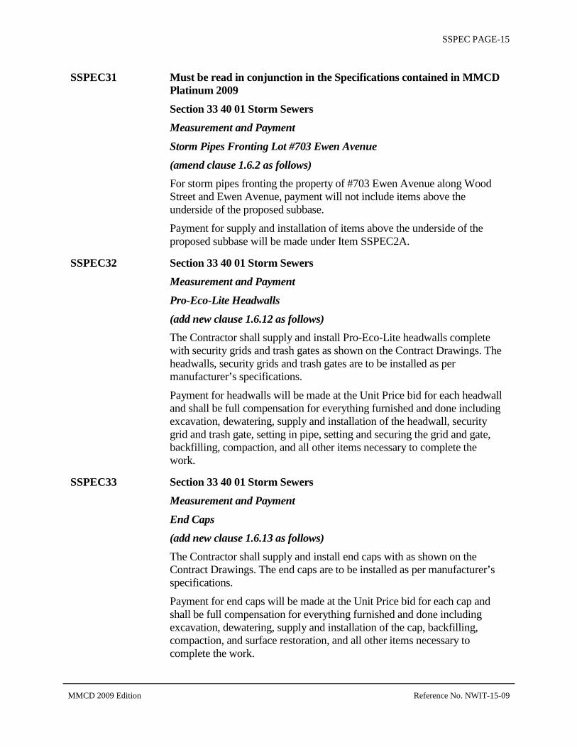
SSPEC PAGE-15
SSPEC31 Must be read in conjunction in the Specifications contained in MMCD Platinum 2009 Section 33 40 01 Storm Sewers Measurement and Payment Storm Pipes Fronting Lot #703 Ewen Avenue (amend clause 1.6.2 as follows) For storm pipes fronting the property of #703 Ewen Avenue along Wood Street and Ewen Avenue, payment will not include items above the underside of the proposed subbase.
Payment for supply and installation of items above the underside of the proposed subbase will be made under Item SSPEC2A.
SSPEC32 Section 33 40 01 Storm Sewers Measurement and Payment Pro-Eco-Lite Headwalls (add new clause 1.6.12 as follows) The Contractor shall supply and install Pro-Eco-Lite headwalls complete with security grids and trash gates as shown on the Contract Drawings. The headwalls, security grids and trash gates are to be installed as per manufacturer’s specifications.
Payment for headwalls will be made at the Unit Price bid for each headwall and shall be full compensation for everything furnished and done including excavation, dewatering, supply and installation of the headwall, security grid and trash gate, setting in pipe, setting and securing the grid and gate, backfilling, compaction, and all other items necessary to complete the work.
SSPEC33 Section 33 40 01 Storm Sewers Measurement and Payment End Caps (add new clause 1.6.13 as follows) The Contractor shall supply and install end caps with as shown on the Contract Drawings. The end caps are to be installed as per manufacturer’s specifications.
Payment for end caps will be made at the Unit Price bid for each cap and shall be full compensation for everything furnished and done including excavation, dewatering, supply and installation of the cap, backfilling, compaction, and surface restoration, and all other items necessary to complete the work.
MMCD 2009 Edition Reference No. NWIT-15-09

SSPEC PAGE-16
SSPEC34 Section 33 40 01 Storm Sewers Measurement and Payment Bends (add new clause 1.6.14 as follows) The Contractor shall supply and install HDPE bends with different sizes at vertical deflections on the proposed storm pipes as shown on the Contract Drawings. The bends are to be installed as per manufacturer’s specifications.
Payment for HDPE bends will be made at the Unit Price bid for each bend with different sizes and shall be full compensation for everything furnished and done including excavation, dewatering, supply and installation of the bend, backfilling, compaction, surface restoration, and all other items necessary to complete the work.
SSPEC35 Section 33 40 01 Storm Sewers Measurement and Payment Drainage Pipe – Trenchless Installation HDPE DR13.5 1050mm OD (add new clause 1.6.2.1 as follows) The Contractor is responsible for the supply and trenchless installation of the 1050mm OD HDPE DR13.5 pipes at the crossing under the existing 900mm diameter GVWD watermain at Wood Street, as shown on the Contract Drawings.
The Contractor shall submit all necessary permit documents (including the detailed installation procedures report described below) and data to Metro Vancouver and shall ensure written approval for the proposed crossing has been obtained prior to commencement of the construction.
The Contractor shall also contact Metro Vancouver at least 14 days prior to proposed installation and ensure Metro Vancouver’s inspectors are on site when the installation is carried out.
The Contractor shall prepare and submit to Metro Vancouver for review and acceptance, a detailed installation procedures report, signed and sealed by a professional engineer licensed in the Province of British Columbia, outlining the method of trenchless installation, the type of equipment to be used, specifics on the installation pits excavation, shoring, dewatering procedures, installation procedures, accuracy of installation, a schedule, quality control processes and emergency contact information.
MMCD 2009 Edition Reference No. NWIT-15-09

SSPEC PAGE-17
The Contractor shall un-cover and expose all underground utilities by hydro-vacuum (daylighting) in the vicinity of the proposed trenchless installation that may be impacted by the installation process. Any impact shall be reported to and the Contract Administrator immediately and if required, shall be repaired by the Contractor, to the satisfaction of the Contract Administrator, at the Contractor’s expense. Contractor shall perform vibration and movement monitoring, as required and at the direction by Metro Vancouver.
The Contractor shall dispose of the material excavated from the installation pits to a Contractor supplied off-Site disposal area or at a location within the Project with the approval of the Contract Administrator. Backfill of the installation pits shall be with approved material.
Within twenty four (24) hours of completion of the pipe installation, the Contractor shall inspect the pipe for cracks, distortions, and any other visible signs of leakage or areas of pipe distress. A report of the findings shall be submitted to the Contract Administrator. Any cracks, distortions, points of leakage or signs of distress shall be repaired by the Contractor, at the Contractor’s expense, to the satisfaction of the Contract Administrator.
Payment for trenchless installation of the 900mm diameter HDPE DR17 pipes will be made at the Unit Price bid and shall be full compensation for everything furnished and done in connection therewith, including obtaining of necessary approvals, retaining a Profession Engineer registered with APEGBC, supply and installation of pipe, removal of material inside the pipe, installation pit excavation and shoring, dewatering, supply and placement of approved backfill material for backfilling of installation pits, compaction, and all other items necessary to complete the work.
Measurement for payment shall be made in lineal metres of pipes installed.
SSPEC36 Must be read in conjunction in the Specifications contained in MMCD Platinum 2009 Section 33 44 01 Manholes and Catchbasins Measurement and Payment Manhole (amend clause 1.5.1.1 as follows) In addition to the MMCD specifications for manholes, the Contractor shall also supply and install the LWG fill materials for subgrade treatment and bedding material, where and as shown on the Contract Drawings.
Only precast manholes are permitted with galvanized or poly-coated steel ladder rungs.
Payment for supply and installation of Light Weight Backfill will be made under Item 3.4.5, SSPEC 9.
MMCD 2009 Edition Reference No. NWIT-15-09

SSPEC PAGE-18
Payment for supply and installation of geosynthetics will be made under Item 31 32 19.
SSPEC37 Must be read in conjunction in the Specifications contained in MMCD Platinum 2009 Section 33 44 01 Manholes and Catchbasins Measurement and Payment Catchbasins Top Inlet with “FISH” symbol (amend clause 1.5.2 as follows) In addition to the MMCD specifications for catchbasins, the Contractor shall also ensure that each catchbasin has a “FISH" symbol on the grate.
SSPEC38 Section 33 44 01 Manholes and Catchbasins Measurement and Payment Cast Iron Catch Basins with “FISH” symbol (add new clause 1.5.2.1 as follows) The Contractor shall supply and install cast iron catch basins at the locations and to invert elevations shown on the Contract Drawings. Catch basins shall be in accordance with BC MOTI 2012 Standard Specifications For Highway Construction, Section 582 and standard drawing SP582-02.05, with a “FISH" symbol on the grate.
Payment for cast iron catch basins will be made at the Unit Price bid for each catch basin and shall be considered as full compensation for everything furnished and done in connection therewith including, excavation, loading, hauling, supply and installation of the complete catch basin, frame and grate, bedding and backfill, and all other items necessary to complete the work.
SSPEC39 Must be read in conjunction in the Specifications contained in MMCD Platinum 2009 Section 03 30 20 Concrete Walks, Curb And Gutter Measurement and Payment Grade Adjustments To Existing Utilities (amend clause 1.4.8 as follows) In addition to the MMCD specifications for adjustments, the Contractor shall adjust all existing manhole lids and risers, catchbasins, and other utilities cover as shown in the Contract Drawings. Measurement will be for each item adjusted. Payment will be made at the Unit Price bid for each item adjusted and shall be considered as full compensation for everything furnished and done in connection therewith the adjustments, and all other items necessary to complete the work.
MMCD 2009 Edition Reference No. NWIT-15-09

SSPEC PAGE-19
SSPEC40 Street Lighting and Traffic Signal Works Must be read in conjunction in the Specifications contained in the City of New Westminster Supplemental Specifications and MMCD Platinum Edition (2009) – Section 26 56 01 and Section 34 41 13
1.0 GENERAL 1.5 Contractor’s Qualifications and Personnel
Add:
.3 All electrical work shall be undertaken by a registered electrical contractor with a valid City of New Westminster or Inter-Municipal business license. Contractor shall be responsible for obtaining all electrical permits, arrange for all electrical utility disconnects and connections, and notify the City of New Westminster Electrical Maintenance Section of the proposed scheduling.
.4 All traffic signal installation work shall be undertaken under the direct supervision of a qualified signal superintendent who must be on-site at all times when work is taking place, and have an alternate when superintendent is not on site.
.5 As a minimum the signal superintendent shall have IMSA Level 1 Signals Certification and/or have completed at least 3 similar signal projects.
Add:
1.11 Work Schedule Add:
.1 The Contractor shall submit for approval to the City Representative prior to commencement of construction a schedule of work setting out the order in which he/she intends to undertake the work. The City Representative may specify the order of work or alter the schedule of work as submitted by the Contractor at any time during the term of the contract.
.2 The Contractor shall arrange a pre-construction meeting with the City Representative and the Contract Administrator prior to construction.
.3 The Contractor shall not receive the “Notice to Proceed” until the Schedule of Work is submitted to the City Representative.
MMCD 2009 Edition Reference No. NWIT-15-09

SSPEC PAGE-20
2.0 PRODUCTS 2.1 General
Add:
.6 The City will supply and install the traffic controller and cabinet.
.7 The City will supply the Contractor, free of all charges, the following:
a) Street name signs;
b) Padlocks.
This equipment will be made available to the Contractor at the City Works Yard. The Contractor shall make all arrangements and pay all costs necessary for the collection of the materials and its delivery to the job site.
The Contractor shall assume responsibility for all materials from the time they are picked up and shall provide suitable storage and protection for these materials until they are installed.
At the time the materials are picked up, the Contractor shall complete a Materials Release Form, and shall check the quantities and verify the correctness of the materials supplied. Any discrepancies or shortages shall be reported immediately to the City Representative.
The Contractor shall give the City Representative a minimum of 7 days’ notice (in writing) prior to the time the equipment is required.
3.0 EXECUTION 3.16 Traffic Controller
Delete .1 to .7 and add:
.1 City of New Westminster shall install the traffic controller cabinet on the concrete base.
.2 Contractor to ensure that all conductors and loop cables have a length that can be extended 2m above the cabinet base. All conductors to be coiled in the main vault prior to City of New Westminster installing cabinet.
.3 Prior to installation of the cabinet by the City of New Westminster, the Contractor shall flash all signal and pedestrian displays. Contractor to also verify continuity of each push button circuit (with pedestrian button depressed).
MMCD 2009 Edition Reference No. NWIT-15-09

SSPEC PAGE-21
3.20 Grounding Add .5
.5 All poles shall be grounded by way of a 20mm x 3.0m long galvanized ground rod.
4.0 MEASUREMENT AND PAYMENT (1.9) Add:
.4 Payment to include all cost for subgrade preparation for Lighting and Traffic Signal Bases.
End of Section
SSPEC41 CITY OF NEW WESTMINSTER SPECIFICATIONS FOR UNDERGROUND ELECTRIC DISTRIBUTION STRUCTURES
1. CITY SUPPLIED MATERIALS
Grounding materials, 12kV switching kiosk pads, 1232 junction vaults, 832 junction vaults, 332 service boxes, 675mm service boxes, single phase LPT fibreglass pyramid pads, and pilasters are supplied by the City of New Westminster and will be available for pick up by the contractor at City Electrical Operations located at 901-1st Street, New Westminster, BC. between the hours of 8:00 am and 3:30 pm Monday to Friday. Precast concrete materials will be available for pick up from the City yard at 734 Boyd Street, (Queensborough) New Westminster, BC. A minimum of 24 hours’ notice is required for pick up of all materials. The contractor shall sign for all materials taken and return all excess and salvaged material to the Electrical operations.
2. TRAFFIC MANAGEMENT
A traffic management plan will be required. Contact Bruce Phillips at 604 527-4693 for more information, The TMP to be planned accordingly to the other works in this Tender.
3. OVER EXCAVATION
Contractor is responsible for locating all utilities, and must provide a unit cost for over excavation.
4. SCOPE The contractor shall supply all necessary materials, labour and equipment to construct and complete the works described on the attached drawings and or specifications as listed in the Tender, unless otherwise noted:
4.1 Installation of three precast 12kV switchgear pads, eight 832
MMCD 2009 Edition Reference No. NWIT-15-09

SSPEC PAGE-22
junction boxes, seven 1232 junction boxes, seven 1Ø LPT fibreglass pyramid pads, three 332 service boxes (1MH lid, 2 square lids) 18 small 675mm diameter service boxes, all grounding materials, and 17 pilasters. (all supplied by the City)
4.2 Supply and Installation of approximately 310 linear trench meters of concrete encased DB2 conduits, 1675 linear trench meters of DB2 conduits in sand; as per drawing C677 sheets 1-4-R0, and the City of New Westminster Specifications for Underground Distribution Structures. (2011-11-26)
This Specification describes the standard work requirements for the construction and installation of underground electrical ducts and structures in accordance with Contract Documents and any details, instructions, and drawings provided by the City.
All work is to be done in a substantial, complete, and workmanlike manner and no details necessary to the proper performance and completion of the work may be omitted even if specific mention of such details is not made in the project documents.
The clauses contained in this Specification shall form a part of any Specification of work or drawings to which they are attached.
5. WORK INCLUDED/NOT INCLUDED
The Contractor is required to furnish all supervision, labour, materials, bricks, tools, trucks and special equipment as may be required to install underground electric distribution plant in accordance with issued plans and specifications.
The contractor shall provide all expendable material items required, not listed in the Project Specifications as being supplied by the City. The Contractor shall be responsible for ensuring that adequate materials are on hand to complete the work.
Included are installation of pilasters, vaults, manholes, spliceboxes, service boxes and duct banks, including the full excavation, form and concrete work, bricking and setting vault, manhole and splicebox frames and covers, laying duct, backfilling, removing and disposal of excavated material, maintenance of backfill, temporary repairing and all other work shown on the drawings or as hereinafter specified.
The Contractor shall supply all duct and accessories, solvent, duct string and warning tape, gravel, sand, reinforcing steel, forming lumber, screws, nails, tape, and other miscellaneous expendable construction items, together with materials required to replace breakages.
MMCD 2009 Edition Reference No. NWIT-15-09

SSPEC PAGE-23
The Contractor shall remove from the site, from time to time, all rubbish, debris, and scrap materials accumulating from the work. Upon completion of the work, the Contractor shall leave the site in a clean and presentable condition.
Temporary and permanent pavement and concrete sidewalk repair shall be completed, by the Contractor, in accordance with the master municipal construction documents.
6. MATERIALS SUPPLIED BY THE CITY
Unless otherwise indicated in the project specifications or drawings, the City will, without charge, supply the Contractor with cast iron frames and covers, pre-cast concrete manholes, counterpoise kits, ground rods and connectors, service boxes, and pilasters.
The Contractor shall be responsible for the sorting, bundling, handling and transporting of all material supplied by the City from the City store or other supply points to the job site. The Contractor shall be responsible for the care and safekeeping of all the City material from the time it is issued to the Contractor until all work is completed and any excess material is returned.
The Contractor shall be responsible for returning all excess new material supplied by the City to the City stores in good order within 72 hours of completion of the work. All new material returned will be documented and acknowledged by the City’s Storekeeper.
The Contractor shall be responsible for returning all material salvaged from the project to the City stores. All salvaged material returned shall be sorted by the Contractor, and will be documented and acknowledged by the City’s Storekeeper.
At all reasonable times the Contractor shall permit representatives of the City to inspect, audit and inventory all the City material in the Contractor’s possession.
7. FIELD SURVEY AND INSPECTION
The Contractor will, unless otherwise indicated in the Project Specifications, set all stakes for running lines and grades for the underground structures. Typically, structures are placed at existing boulevard, sidewalk or pavement elevations. Changing grades for new sidewalks or pavement are available from the engineering plans. Setting of additional reference hubs or stakes that may be required by the Contractor shall be included in the contract price.
All work performed under the terms of the Project Specifications will be subject to continuous and rigid inspection by the City's representative, and the work will not be accepted as complete until final acceptance has been clearly given.
MMCD 2009 Edition Reference No. NWIT-15-09
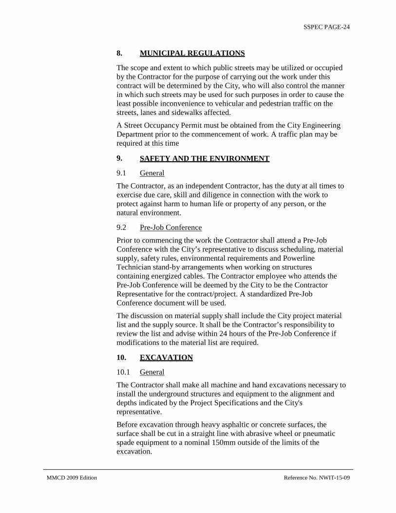
SSPEC PAGE-24
8. MUNICIPAL REGULATIONS
The scope and extent to which public streets may be utilized or occupied by the Contractor for the purpose of carrying out the work under this contract will be determined by the City, who will also control the manner in which such streets may be used for such purposes in order to cause the least possible inconvenience to vehicular and pedestrian traffic on the streets, lanes and sidewalks affected.
A Street Occupancy Permit must be obtained from the City Engineering Department prior to the commencement of work. A traffic plan may be required at this time
9. SAFETY AND THE ENVIRONMENT
9.1 General
The Contractor, as an independent Contractor, has the duty at all times to exercise due care, skill and diligence in connection with the work to protect against harm to human life or property of any person, or the natural environment.
9.2 Pre-Job Conference
Prior to commencing the work the Contractor shall attend a Pre-Job Conference with the City’s representative to discuss scheduling, material supply, safety rules, environmental requirements and Powerline Technician stand-by arrangements when working on structures containing energized cables. The Contractor employee who attends the Pre-Job Conference will be deemed by the City to be the Contractor Representative for the contract/project. A standardized Pre-Job Conference document will be used.
The discussion on material supply shall include the City project material list and the supply source. It shall be the Contractor’s responsibility to review the list and advise within 24 hours of the Pre-Job Conference if modifications to the material list are required.
10. EXCAVATION
10.1 General
The Contractor shall make all machine and hand excavations necessary to install the underground structures and equipment to the alignment and depths indicated by the Project Specifications and the City's representative.
Before excavation through heavy asphaltic or concrete surfaces, the surface shall be cut in a straight line with abrasive wheel or pneumatic spade equipment to a nominal 150mm outside of the limits of the excavation.
MMCD 2009 Edition Reference No. NWIT-15-09

SSPEC PAGE-25
10.2 Proving Route
Grades of the trench, ducts, and structures shall be proven far enough along the route in advance of duct laying or forming and concreting that any relocation or redesign necessitated by unforeseen obstacles may be carried out.
It is essential that the Contractor prove the location of any existing utility by digging test holes or other equivalent method satisfactory to the City's representative. The Contractor shall not install a chamber until the next chamber has been fully excavated, and the intervening duct line proven feasible. Any ducts or chambers constructed by the Contractor in contravention of these requirements, and which have to be relocated or redesigned because of an unforeseen obstacle along the route, shall be demolished, removed from the site, and replaced at the Contractor’s expense.
10.3 Basis of Tender
Unless otherwise specified in the Project Specification, the Contractor shall prepare Tenders on the basis that the entire excavation will be common excavation and will be immediately removed from the site.
The Contractor must also quote unit prices for rock excavation and extra common excavation as defined herein. These unit prices shall include removal of excavated material.
10.4 Material Definitions
All excavated material shall be classed as either “common excavation" or “rock excavation" as defined in the following paragraphs:
(a) Common Excavation
Common excavation will include such materials as are commonly called earth, loam, clay, muck, sand, gravel, gumbo, boulders each less than 1 m³ in void, angular rock fragments, hardpan, pavement, and all other materials of every description not defined as “rock excavation".
(b) Rock Excavation
The term “rock" is hereby defined as:
(i) Solid formations of dense homogeneous sedimentary or igneous material which require, in the judgement of the City's representative, the continuous blasting, drilling or wedging for their removal. In order to qualify for payment under the unit price for rock excavation, material so removed shall measure at least 1 m³ in void within the limits of excavation as defined herein.
MMCD 2009 Edition Reference No. NWIT-15-09

SSPEC PAGE-26
(ii) Individual boulders of any type measuring at least 1 m³. Payment for excavation of this type of material shall be based upon the amount in cubic metres of boulders removed within the limits of excavation as defined herein.
The breaking and removing of road or sidewalk pavements or frozen material, regardless of thickness, will in no case be taken as rock excavation.
10.5 Unit Price Excavation
The Contractor will be additionally compensated for any “rock excavation" or extra “common excavation" removed from the trench in accordance with the relevant Unit Price. Measurement for payment of additional or deleted quantities of excavation will be as defined in the “Basis of Measurement" clause below.
If, after obstructions have been proven or after any trench has been excavated, the City's representative should decide to change the depth or location of any trench or structure, the Contractor will be paid for any additional excavation (but not that excavation included in the “Basis of Tender" clause above) according to the volumes excavated, as defined in the “Basis of Measurement" clause below. However, no allowance will be made for any additional excavation unless the change in grade exceeds 150mm.
Similarly, if the City's representative should change the depth or location of any trench or structure thereby reducing the necessary excavation, the cost of deleted excavation will be deducted from payments owing the Contractor; however, no deduction will be made for any deleted excavation unless the change in grade exceeds 150mm.
10.6 Basis of Measurement
(a) Common Excavation
(i) Trench Work
Volume measured in void with the excavation limits set at 75mm below the duct bank sub-grade and 150mm outside each side of the duct bank, including any concrete encasement, as shown on the drawings, except that where the safety shoring recommendations of WorkSafe BC require additional width of trench to install such shoring, then the payment shall be based on these widths.
(ii) Chambers
Volume measured in void with the excavation limits set at 100mm below sub-grade and 300mm outside each side of the chamber outline as shown on the drawings.
MMCD 2009 Edition Reference No. NWIT-15-09
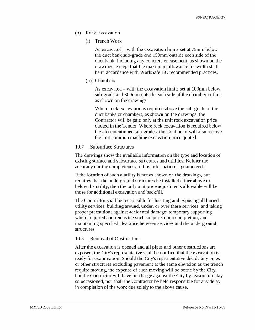
SSPEC PAGE-27
(b) Rock Excavation
(i) Trench Work
As excavated – with the excavation limits set at 75mm below the duct bank sub-grade and 150mm outside each side of the duct bank, including any concrete encasement, as shown on the drawings, except that the maximum allowance for width shall be in accordance with WorkSafe BC recommended practices.
(ii) Chambers
As excavated – with the excavation limits set at 100mm below sub-grade and 300mm outside each side of the chamber outline as shown on the drawings.
Where rock excavation is required above the sub-grade of the duct banks or chambers, as shown on the drawings, the Contractor will be paid only at the unit rock excavation price quoted in the Tender. Where rock excavation is required below the aforementioned sub-grades, the Contractor will also receive the unit common machine excavation price quoted.
10.7 Subsurface Structures
The drawings show the available information on the type and location of existing surface and subsurface structures and utilities. Neither the accuracy nor the completeness of this information is guaranteed.
If the location of such a utility is not as shown on the drawings, but requires that the underground structures be installed either above or below the utility, then the only unit price adjustments allowable will be those for additional excavation and backfill.
The Contractor shall be responsible for locating and exposing all buried utility services; building around, under, or over these services, and taking proper precautions against accidental damage; temporary supporting where required and removing such supports upon completion; and maintaining specified clearance between services and the underground structures.
10.8 Removal of Obstructions
After the excavation is opened and all pipes and other obstructions are exposed, the City's representative shall be notified that the excavation is ready for examination. Should the City's representative decide any pipes or other structures excluding pavement at the same elevation as the trench require moving, the expense of such moving will be borne by the City, but the Contractor will have no charge against the City by reason of delay so occasioned, nor shall the Contractor be held responsible for any delay in completion of the work due solely to the above cause.
MMCD 2009 Edition Reference No. NWIT-15-09

SSPEC PAGE-28
If the Contractor wishes to temporarily remove, disconnect, or relocate service pipes crossing the excavation to facilitate installation of the underground structures, they shall make their own arrangements with the owners of the service pipes and shall bear all costs of such temporary work. The City will neither guarantee that such temporary work may be done nor bear any cost of such temporary work. Payments for all such temporary work shall be made directly by the Contractor.
Disconnected or abandoned utilities shall not be removed or salvaged without the permission of the City's representative.
10.9 Irregularities in Excavation
All irregularities and cavities in the bottom of the trench or excavation shall be filled up to the required sub-grade with approved backfill material properly tamped in place.
10.10 Adjacent Structures and Properties
Prior to excavation, the Contractor shall consult and cooperate with owners of adjacent structures which may be endangered, or whose gardens, trees, tree roots, and shrubs require protection or alteration during construction, to eliminate future dispute and litigation over that which may already be in a damaged condition. Under no circumstances shall the Contractors permit their forces, materials, and/or equipment to encroach on private properties adjacent to the work, without the express consent of the City's representative. Any survey pins displaced during the construction work shall be reinstalled by a legal surveyor at the Contractor's expense.
10.11 Drainage and Shoring
The Contractor shall, without additional charge, construct such temporary drains or do such dewatering of the trench and chamber excavations as may be necessary to keep water away from concrete work until the concrete has thoroughly set.
Without additional charge, the Contractor shall provide and place adequate shoring as required by WorkSafe BC and as required to protect adjacent paving and structures, and to prevent any sloughing in of material that is under adjacent sections of sidewalk, road pavement, pipes, or ducts.
11. UNDERGROUND DUCTS, CHAMBERS, AND TRANSFORMER PADS
The location, number, and arrangement of ducts, chambers, transformer pads, and service boxes shall be as shown on the drawings. Ducts may be directly buried, concrete encased, or a combination of both as specified on the drawings. The size, shape, routing, and concrete encasement of ducts between terminations may be varied by the City's representative
MMCD 2009 Edition Reference No. NWIT-15-09
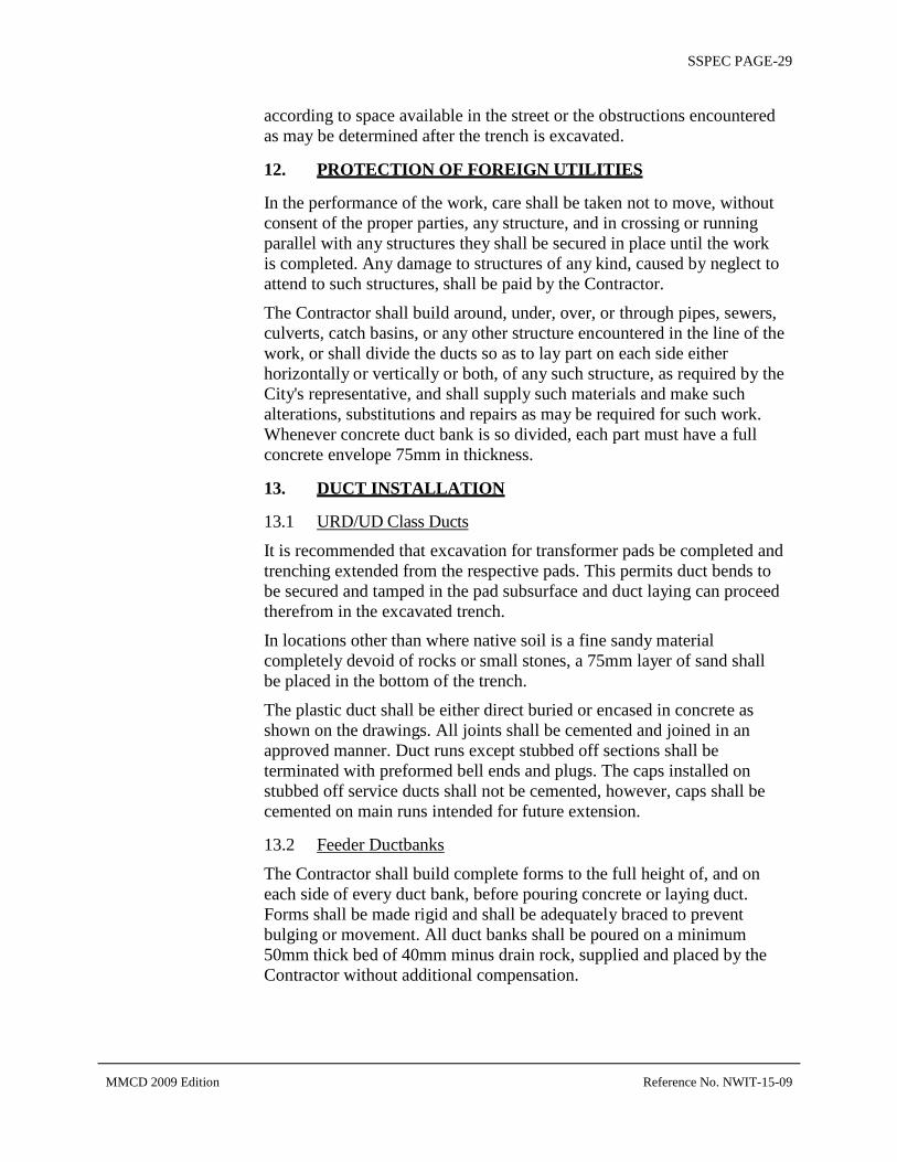
SSPEC PAGE-29
according to space available in the street or the obstructions encountered as may be determined after the trench is excavated.
12. PROTECTION OF FOREIGN UTILITIES
In the performance of the work, care shall be taken not to move, without consent of the proper parties, any structure, and in crossing or running parallel with any structures they shall be secured in place until the work is completed. Any damage to structures of any kind, caused by neglect to attend to such structures, shall be paid by the Contractor.
The Contractor shall build around, under, over, or through pipes, sewers, culverts, catch basins, or any other structure encountered in the line of the work, or shall divide the ducts so as to lay part on each side either horizontally or vertically or both, of any such structure, as required by the City's representative, and shall supply such materials and make such alterations, substitutions and repairs as may be required for such work. Whenever concrete duct bank is so divided, each part must have a full concrete envelope 75mm in thickness.
13. DUCT INSTALLATION
13.1 URD/UD Class Ducts
It is recommended that excavation for transformer pads be completed and trenching extended from the respective pads. This permits duct bends to be secured and tamped in the pad subsurface and duct laying can proceed therefrom in the excavated trench.
In locations other than where native soil is a fine sandy material completely devoid of rocks or small stones, a 75mm layer of sand shall be placed in the bottom of the trench.
The plastic duct shall be either direct buried or encased in concrete as shown on the drawings. All joints shall be cemented and joined in an approved manner. Duct runs except stubbed off sections shall be terminated with preformed bell ends and plugs. The caps installed on stubbed off service ducts shall not be cemented, however, caps shall be cemented on main runs intended for future extension.
13.2 Feeder Ductbanks
The Contractor shall build complete forms to the full height of, and on each side of every duct bank, before pouring concrete or laying duct. Forms shall be made rigid and shall be adequately braced to prevent bulging or movement. All duct banks shall be poured on a minimum 50mm thick bed of 40mm minus drain rock, supplied and placed by the Contractor without additional compensation.
MMCD 2009 Edition Reference No. NWIT-15-09

SSPEC PAGE-30
Duct banks shall be installed in accordance with the following procedure:
(a) After the grade of the trench has been checked by the City's representative, a 75mm base of stiff concrete shall be poured in sufficient quantity that the bottom row of ducts may be laid before the concrete has attained its initial set.
(b) The duct shall be checked for defects in material and structure before being placed in the trench. Any field-cut ducts or bends shall have their inside edges beveled smooth by sanding. The bottom row of ducts shall then be laid, with open ends closed with plugs secured to prevent removal by hand. Any work done to repair or connect to existing transite ducts must comply with approved methods and regulations for working with asbestos cement duct.
(c) For 4-inch and 5-inch ducts, a separation of 45mm, both vertically and horizontally, shall be maintained between ducts by the use of approved separators of the correct dimensions. However, vertical separation shall be increased to 115mm before entering a manhole, unless otherwise noted on the drawings. Increase in vertical separation shall begin a minimum of 6m back from the outside face of the manhole.
(d) The duct joints shall be staggered at least 150mm from neighbouring duct joints in both the vertical and horizontal rows.
(e) After the alignment has been checked by the City's representative, the concrete sheathing and fill shall be poured around the ducts to the level set by the City's representative. The Contractor shall ensure that the correct duct separations and thicknesses of concrete are maintained at all times.
(f) The separators shall then be removed and the holes filled with concrete.
(g) The next horizontal row of ducts shall then be laid and the same procedure repeated until the required section is obtained and the top 75mm concrete sheathing is complete.
(h) The ends of ducts in a run, which will be extended later, shall be staggered and shall extend at least 300mm beyond the end of the concrete envelope. The open ends of these ducts shall be closed with caps cemented in place.
13.3 Mandrelling and Duct String
(a) URD/UD Class Ducts:
The ducts shall be proven clean and free of obstructions or faulty joints by use of a Greenlee Piston or an acceptable combination of mandrell, swab, and wire brush to the satisfaction of the City's representative.
MMCD 2009 Edition Reference No. NWIT-15-09

SSPEC PAGE-31
(b) Feeder Class Ducts:
When the duct work is completed and the concrete and mortar thoroughly set, a test mandrel shall be drawn through each duct in the presence of the City's representative. The test mandrel will be comprised of a wire brush, cutter and disc type mandrel (General Machine Products attachment Part No. 25, Cat. No. G-1011, followed by Part No. 27 or equivalent, sized according to the duct). The minimum diameter of such mandrels shall be 0.5 inch below the nominal duct size.
After test-mandrelling, an approved light waterproof cord shall be left through all ducts or as designated by the City’s representative
13.4 Feeder Duct Measurements
Duct measurement shall be from centre to centre of chamber covers, or centre of chamber cover to centre of terminal poles, measured horizontally, less the distance from centre of chamber cover to face of duct where it enters each chamber.
14. CHAMBERS
14.1 General
Chambers are vaults, manholes, spliceboxes, and similar structures. Some chambers are prefabricated and will be designated as such on the drawings and supplied from the City stores or manufacturer's plant depending upon size.
14.2 Chambers Built on Site
Chambers built on site shall be in accordance with the contract drawings except where changes to location and shape are authorized by the City's representative.
Floor slabs shall be poured on a minimum 50mm thick bed of 40mm minus drain rock supplied, placed, and compacted by the Contractor.
After formwork is completed care, shall be taken in placing concrete for wall cavities. Concrete lifts for such cavities shall not exceed 300mm and concrete for such lifts shall be first placed on the manhole roof form or a pouring deck before placing into wall cavities. Concrete shall not be poured directly into wall cavities. Wall pours must be continuous until completed.
The top of the chamber roof and the chamber casting shall be set to conform to the line of the street or as otherwise determined by the City's representative. Manhole openings shall have a 75mm chamfer at the bottom. Manholes are normally built with a brick chimney, cement rendered inside and out, extending from the chamber roof slab to the underside of the cover castings to allow for any subsequent lowering of
MMCD 2009 Edition Reference No. NWIT-15-09

SSPEC PAGE-32
street grade. Cement bricks or equivalent materials are to be supplied and installed by the Contractor for this purpose as required by the City's representative. The Contractor shall also install a 250mm ventilation hose casting in a manner similar to the manhole lid.
14.3 Precast Chambers
(a) Base Preparation
(i) The excavation shall be completed and roughly leveled to the proper elevation.
(ii) Timber screeds shall then be set to the elevation of the base of the precast chamber. The screeds shall be leveled to a tolerance of ±6mm.
(iii) 150mm of 40mm minus drain rock or sand shall be placed, leveled, compacted to 90% Modified Proctor, and struck-off level with the top of the timber screeds.
(iv) During this base preparation the precast sump and drainage duct shall be installed. If not connected immediately, drainage duct shall stubbed off at least 600mm beyond the manhole wall in the direction indicated by the City's representative.
(v) Under wet conditions, at the discretion of the City's representative, the above 150mm layer of drain rock shall be increased to 200mm.
(b) Placing
(i) Manhole sections shall be placed with great care. The responsibility of off-loading and placing manholes (or sections) into excavations shall be the Contractor's. Care shall be taken to maintain adequate clearances from hoist booms to overhead conductors.
(ii) Gaskets – Care shall be taken to place precast sections so that gaskets between sections are totally contained and compressed.
(iii) Sumps – A suitable sealing grout shall be placed, at the City representative's direction, between sump and base of manhole.
MMCD 2009 Edition Reference No. NWIT-15-09

SSPEC PAGE-33
14.4 Duct Terminations
The Contractor shall terminate all ducts with bell ends installed 75mm back from the inside face of chamber walls when poured in place (25mm back when precast), and shall finish the recesses with chamfered edges in a clean and workmanlike manner. For precast manholes any wall openings shall be filled with concrete to the satisfaction of the City's representative.
Where the drawings indicate a future duct bank on any face of a chamber, a brick window 100mm thick, cement rendered both sides, shall be provided.
14.5 Chamber Designations
Each manhole lid shall be permanently identified by the Contractor with the letters CNWE and the manhole number (MHXXX).
Secondary service boxes shall be identified with the letters CNWE only
14.6 Irons, Hooks, Rods, and Inserts
The Contractor shall set pull-in irons, hooks, and inserts as shown on the contract drawings or as specified by the City's representative.
The Contractor shall install in each manhole and vault, at points designated by the City's representative, suitable grounding rods about 9 feet long, driven at a 45 angle downward into the ground so that the upper ends shall project into the manhole about 100mm.
14.7 Drainage
(a) All manholes and vaults shall be provided with a sump. Manholes and vaults shall be drained as shown on the drawings or as required by the City's representative. Drain pipes shall be of approved grade of vitrified clay, or PVC. Backwater valves and P-traps with cleanout and strainers shall be installed as shown on the drawings or as required by the City's representative.
(b) All drainage pipe, valves and P-traps shall be provided by the Contractor.
(c) Connection of drains to City sewers or catch basins will normally be done by the Contractor. Drainage excavations shall then be back-filled to the same standards as set for duct excavation. All costs of installing and backfilling drains shall be included in the lump sum bid price. Under no circumstances will laying of drains as shown on construction drawings be considered as unit price or extra work.
MMCD 2009 Edition Reference No. NWIT-15-09

SSPEC PAGE-34
14.8 Removal of Forms and Traffic Loading
Inside roof forms of poured-in-place chambers will not be removed for a minimum of 14 days if the chamber is in the sidewalk and 21 days if in the travelled road.
Poured-in-place chambers shall not be subjected to traffic loading for 21 days unless otherwise directed by the City's representative.
15. BACKFILL
15.1 General
The Tenderer shall allow for the supply and placement of backfill materials in accordance with these Tender Documents, and the clean-up after backfill.
Backfill will normally be imported granular or sand material (see below). However, native materials may be used, at the City representative's discretion, if location and soil conditions are considered satisfactory, and/or if specified in the Project Specifications.
15.2 Backfill Materials
Unless otherwise specified in the Project Specifications or by the City's representative, the excavation shall be backfilled as follows:
(a) To 150mm above direct buried ducts or 200mm above concrete encased ducts with approved sand, hand tamped. A portable plate vibrator may be used at the discretion of the City's representative.
(b) From the point specified in (a) above to the point specified in (c) below with any of the following materials, providing all materials are compacted in accordance with the compaction clause below. Backfill shall be done in maximum lifts of 300mm (loose) for imported material or 150mm to 200mm (loose) for native material unless otherwise specified by the City's representative. Warning tape reading, as a minimum, “Caution Buried Electric Line Below" shall be supplied and installed by the Contractor at a depth of 300mm below finished grade.
(i) Sand
Sand shall be free of organic materials, clay or silt. 100% shall pass a 5mm sieve, 90 – 100% shall pass a 2mm sieve and not more than 5% shall pass a 75m mesh sieve by mass. Fraser River pump sand is acceptable.
(ii) Combined Crushed Aggregate Fill
This fill shall be free from organic materials, clay or silt. The fraction retained on a 10mm sieve shall be at least 50% crushed. The fraction passing a 75m mesh sieve shall be not more than 5% by mass.
MMCD 2009 Edition Reference No. NWIT-15-09

SSPEC PAGE-35
(iii) Select Backfill
This material shall be essentially granular and shall not contain stones larger than 75mm, organic material, silt or clay. The fraction passing a 75m mesh sieve shall not be more than 5% by mass.
(iv) Native or Random Backfill
This material may be used, if the required compaction can be obtained. Compaction ability is very dependent upon water content and to obtain approval for use of this material the Contractors may be called upon to demonstrate their methods and machinery to prove to the City's representative that the compaction requirements can be met. In any event, all stones larger than 150mm must be removed.
(c) The top zone of the excavation shall be backfilled with 300mm of 20mm minus combined crushed aggregate fill where the excavation is situated in a paved or travelled road; 150mm of 20mm minus combined crushed aggregate where the excavation is situated in a sidewalk; 150mm of black loam where the excavation is situated in a developed grass boulevard. All these materials shall be thoroughly compacted after placement.
(d) In all locations where road paving or sidewalk has been removed for trench excavation the Contractor shall, unless otherwise directed, supply and place a temporary tamped asphalt patch within 24 hours of backfilling to facilitate the movement of traffic and pedestrians until permanent repairs are made. Compacted thicknesses shall be 50mm for roads and 25mm for sidewalks.
(e) In all locations where the excavation is located in developed grass boulevards, the Contractor shall neatly cut the grass sod and store it in a suitable location. After backfill is completed the black loam shall be leveled off, raked clear of stones and debris and the grass sod replaced. If the Contractors damage the adjacent grass, or are unable to preserve the grass sod, they shall resod the boulevard. The Contractor shall be responsible for maintaining sod until it has grown to a condition similar to that existing before excavations were begun. If, in the opinion of the City's representative, the time of year is not suitable for resodding, the Contractor will be required to carry out this work at a more seasonable time.
(f) Backfilling of all voids around chambers shall be done with river sand or other approved material.
MMCD 2009 Edition Reference No. NWIT-15-09

SSPEC PAGE-36
The supply and placement of all the above backfill materials including the supply and placement of sand for the minimum cover over all ducts, and the disposal of any native excavated backfill materials, shall be the responsibility of the Contractor, and shall be included in the Contractor's lump sum tender.
15.3 Compaction of Backfill
All excavations shall be backfilled with specified materials, placed in layers, and compacted to the following requirements unless otherwise indicated in the project specifications:
Minimum Corrected Dry Density**
(a) Trench in boulevards (assuming that excavated trench is greater than excavated depth distance from roadway, sidewalk, curbs, walls, or structures)
85%
Trench in all other areas:
Within 1.2m of the surface 95%
Depths below 1.2m from surface 85%
** In accordance with ASTM D1557-66T (Modified Proctor) and shall be corrected for material retained on No. 4 Sieve according to the following formula:
D = Pf x Df + Pt x 0.90 x 62.4G
100 100
Where: D = corrective maximum dry density in pounds per cubic foot for total sample,
Pf = percent of total sample passing the No. 4 sieve,
Df = maximum dry density in pounds per cubic foot (ASTM D1557-66T) for material passing the No. 4 sieve,
Pt = percent of total sample retained on the No.4 sieve,
G = bulk specific gravity (dry basis) of material retained on the No. 4 sieve (ASTM C127-59).
Upon request of the City's representative, the Contractors shall, at their own expense, provide certified test results demonstrating that the above compaction requirements have been met.
MMCD 2009 Edition Reference No. NWIT-15-09

SSPEC PAGE-37
15.4 Unit Price Work – Backfill
Additional unit price excavation shall be backfilled with material specified by the City's representative. Unit prices for such materials shall be provided by the Contractor; measurement shall be in accordance with the Basis of Measurement clause above.
15.5 Acceptability of Backfill Material
Notwithstanding the backfill materials herein specified, all materials must be satisfactory to the City.
15.6 Maintenance of Backfill
As part of the work the Contractors shall maintain the backfilled excavation at their own expense until all settlement has ceased, except that on paved streets they shall maintain the backfilled trenches and temporary surfaces for 45 days after completion of backfill. This “completion” will be done on a section-by-section basis and the 45-day period will not commence until the City representative's written approval has been obtained that the backfill of a particular section is completed.
15.7 Liability
In accepting the responsibility for maintenance of backfill, the Contractor shall be fully responsible for any damage or accident to persons and/or property resulting from the condition of the backfilled trench.
16. PLAIN AND REINFORCED CONCRETE AND MORTAR
16.1 Applicable Standard Specifications
Except as otherwise specified or shown on drawings, concrete shall comply with the current A-23 Canadian Standard for Concrete and Reinforced Concrete; A-23.1 Concrete Materials and Methods of Concrete Construction and A-23.2 Methods of Test for Concrete.
16.2 Gravel
Stone or gravel used in normal concrete for underground construction shall include all the aggregate too large to pass through a 5mm mesh and that which will pass through a 20mm mesh. Stone or gravel shall be clean, hard, durable, and well graded.
16.3 Concrete
All concrete shall be proportioned to have a compressive strength of not less than 20 MPa at 28 days. Slump shall be maximum 80mm and minimum 20mm. Concrete for manholes to be compacted by mechanical vibration shall have the following maximum and minimum slump:
Floors and roofs -- 50mm maximum, 20mm minimum. Walls -- 80mm maximum, 20mm minimum.
MMCD 2009 Edition Reference No. NWIT-15-09

SSPEC PAGE-38
16.4 Mortar
Mortar shall be composed of one part cement and three parts sand by volume, and water, all as previously specified. Mortar that has been mixed over ½ hour or that has commenced to set shall not be used. The mortar shall be as dry as practicable to obtain adhesion. Not more than 5% of Mason's Hydrated Lime shall be added to the mortar.
16.5 Admixtures
The use and choice of concrete admixtures will be subject to the approval of the City's representative, but the expense of using admixtures shall be borne by the Contractor.
Air-entraining admixtures if used, shall conform to the requirements of ASTM designation C-260-Current. A cement dispersant may be used at the option of the supplier, with the approval of the City's representative.
16.6 Air Entrainment
The total air content of the concrete at the time of placing shall be 6% ± 1%.
16.7 Concrete Inspection
To ensure that these requirement are met, test results on concrete shall be supplied to the City's representative upon request.
17. COMPLETION TIME
Within 5 days of receipt of purchase order, the Contractor shall submit to the City's representative for approval, a progress schedule showing the proposed dates of the commencement and completion of the project in the time specified.
18. PERMANENT REPAVING
Unless otherwise specified in the Project Specifications the Contractor will be required to complete the permanent repaving of excavated areas. The work will normally be done as follows, unless otherwise specified in the Project Specifications:
Cut (saw cut if necessary) pavement to nominal 150mm outside of trench width including adjacent extremities of surface damage, settlement or cracking.
Remove temporary patch and sufficient backfill to replace with a minimum of 75mm compacted hot asphaltic material to the elevation of the existing road grade.
No permanent repaving shall be done at air temperatures below -1 C or when the subgrade is frozen.
MMCD 2009 Edition Reference No. NWIT-15-09

SSPEC PAGE-39
In addition to the above, other work including permanent sidewalk and curb and gutter restoration will, if required by the Project Specification, be completed to the satisfaction of the City.
19. MEASUREMENT AND PAYMENT
Measure for payment will be per linear metre or count as measured horizontally in the field. Payment for linear meter or count installed includes necessary trenching, earthworks and incidentals for completion of the work. Trenching and earthworks for conduits installation in the north and south common trenches is shown on Dwg T-002. All duct termination points shall be marked by a 2X4 and recorded on the as-constructed drawing set. All items for payment by count or linear meters shall include necessary connections to drains and related drainage work. Payment also includes necessary work as mentioned in the above item 4.0 SCOPE for the completion of items on the Tender Form.
SSPEC42 SHAW STRUCTURE AND UNDERGROUND DUCT INSTALLATION DETAILS SUPPLY OF MATERIALS:
5686 Service Boxes,1.5 vaults, 4828 pedestals are supplied by Shaw Cable systems and will be available for pick up by the contractor from Armtec
Shipping & Receiving: 5353 – 192nd Street, Surrey, BC, V3S 8E5
Phone: (604) 576-1808Fax: (604) 576-2454 Direct line:604-576-5651
List of Materials as follows:
MMCD 2009 Edition Reference No. NWIT-15-09

SSPEC PAGE-40
SPEC42
MMCD 2009 Edition Reference No. NWIT-15-09

SSPEC PAGE-41
Shaw pipes and fittings are supplied by Shaw Cable systems and will be available for pick up by the contractor from Corix Water Products
f19900-84th Avenue, Langley, BC, V2Y 3C2 Phone: (604) 455-3505 Fax: (604) 455-3523
List of Materials as follows:
MMCD 2009 Edition Reference No. NWIT-15-09

SSPEC PAGE-42
MMCD 2009 Edition Reference No. NWIT-15-09

SSPEC PAGE-43
SHAW STANDARDS:
SHAW follows MMCD standards and the City of New Westminster specifications. When discrepancies arise, Shaw will follow the standards of the City of New Westminster.
SCOPE:
The contractor shall install SHAW supplied material and complete the works described on the attached drawings and or specifications as listed in the Tender, unless otherwise noted.
Measure for payment will be per linear metre or count as measured horizontally in the field. Payment for linear meter or count installed includes necessary trenching, earthworks and incidentals for completion of the work. Trenching and earthworks for conduits installation in the north and south common trenches is shown on Dwg T-002. All duct termination points shall be marked by a 2X4 and recorded on the as-constructed drawing set. All items for payment by count or linear meters shall include necessary connections to drains and related drainage work.
SSPEC43 SPARE DUCTS SPARE DUCTS follows MMCD standards and the City of New Westminster specifications. When discrepancies arise, Shaw will follow the standards of the City of New Westminster.
SCOPE – Supply & Installation:
The contractor shall supply all necessary materials, labour and equipment to construct and complete the works (Spare Ducts) described on the attached drawings and or specifications as listed in the Tender, unless otherwise noted:
Measure for payment will be per linear metre or count as measured horizontally in the field. Payment for linear meter or count installed includes necessary trenching, earthworks and incidentals for completion of the work. Trenching and earthworks for conduits installation in the north
MMCD 2009 Edition Reference No. NWIT-15-09

SSPEC PAGE-44
and south common trenches is shown on Dwg T-002. All duct termination points shall be marked by a 2X4 and recorded on the as-constructed drawing set. All items for payment by count or linear meters shall include necessary connections to drains and related drainage work.
SSPEC44 Must be read in conjunction in the Specifications contained in BCNTA/BCSLA Standards Current Edition Measurement and Payment Cobble Paving/ Rumble Strips. Measure for payment will be per square metre, to include excavating, granular base, concrete slab and thickset mortar bed for cobbles. Cobbles are to be installed as per drawings.
SSPEC45 Cathodic Protection For City of New Westminster Watermains The Contractor shall install polyethylene encasement of the pipe sections and related fittings.
Measurement and Payment Payment for polyethylene encasement is considered incidental to related watermain installation, and no separate payment will be made.
For Metro Vancouver Watermains The Contractor shall install corrosion protection measures as shown on the design drawings and reports prepared by Corrosion Service Company Limited (Reference Document – Attachment 8)
The following specifications shall be followed:
1.0. MATERIALS
1.1. Field Applied Pipe Encasement and Coatings 1.1.1. For Ductile Iron Pipe: Filed applied polyethylene sleeves
shall conform to ANSI/AWWA Standard C105 (latest edition) for polyethylene encasement of ductile iron pipe systems. The minimum sleeve thickness shall be 8 mils.
1.1.2. For Ductile Iron: Cold applied Petrolatum Tape and Wax shall confirm to ANSI/AWWA C217 (latest edition). Denso Tape & Paste or approved alternate.
1.1.3. For ductile Iron: Cold applied Mastic: Royston A51 mastic or approved alternate.
MMCD 2009 Edition Reference No. NWIT-15-09

SSPEC PAGE-45
1.2. Pipe to Cable Bonding 1.2.1. Continuity Bonding Cables: All bond cables installed
across pipe joints or other electrical discontinuities shall be 7 strand, #6 AWG copper conductor, with Black RWU insulation, CSA approved for the application.
1.2.2. Thermite Weld Connection: All pipe bonds shall be completed with the thermite weld process. Approved manufacturers Cadweld or Thermoweld. Molds and charges shall be appropriately sized for the application as recommended by the manufacturer.
1.3. Electrical Isolation: Mechanical connection to unprotected, metallic foreign service lines shall be isolated with one of the following:
1.3.1. Flange Isolation Kit: Full Face, Type E, phenolic core, neoprene faced gasket complete with isolating sleeves (one or two piece) and steel washers.
1.3.2. Isolating Boot: Robar type isolating boot suitable for use with pipe couplings. An isolating sleeve and washer on each tie-rod, if installed.
1.3.3. Service Line: Isolate all metallic services connections at the property line with insulated curb valve and insulated corporation ball value or equivalent. Meuller Company or approved alternates may be used.
2.0. INSTALLATION
2.1. Field Applied Polyethylene Encasement (Ductile Iron Pipe)
2.1.1. Specification: Field installed polyethylene encasement sleeves shall conform to ANSI/AWWA Standard C105 (latest edition) for polyethylene encasement of ductile iron pipe systems.
2.1.2. Application: Each pipe shall be clean of foreign containments. The polyethylene sleeve shall be folded to conform to the contour of the pipe. The installed encasement shall be free of perforations and other damage. The sleeves shall be secured in place with adhesive tape with pipe joints overlapped a minimum 300mm. All pipe restraints and fittings shall not be encased.
2.1.3. At transitions to petrolatum taping a min 300mm overlay of the encasement shall be provided complete with a taped seal.
MMCD 2009 Edition Reference No. NWIT-15-09
SSPEC PAGE-46
2.1.4. To help prevent damage to encasements provide single layer of petrolatum tape over weld connections and other protrusions.
2.2. Field Applied Coatings 2.2.1. Specification: Referenced standard ANSI/AWWA C-
217 (Latest Version) “Cold Applied Petrolatum Tape and Wax for the Exterior of Special Sections, Connections and Fittings for Buried Steel Water Pipelines”.
2.2.2. Application: All pipe couplings and other irregular fittings shall be field coated with petrolatum tape and wax. Requirements as indicated in C-217 and as recommended by the manufacturer.
2.2.3. Structure Coating Repair: Tape coatings removed for the thermite weld process connections shall be restored with an approved material suitable for the application, including cold application mastic Royston A51. Application as recommended by the manufacturer.
2.3. Electrical Isolation 2.3.1. Main Line Connections: Electrically isolate the
protected watermain from unprotected metallic services including other watermains at endpoints and other tie-ins, service connections and at all other foreign tie-ins and connections at the pump station.
2.3.2. Foreign Structures: Ensure proper electrical isolation of the protected watermain from all metallic foreign structures including chamber fittings and re-bar, sampling lines, electrical services and foreign pipelines.
2.4. Electrical Continuity 2.4.1. Application: All piping, fittings and other mechanically
connected provisions within the scope of the protected watermain shall be cathodically protected.
2.4.2. Bond Connections: To ensure proper electrically continuity throughout the protected watermain section, provide two bond wire connections across each pipe joint and at all other non-flanged fittings and connections as required.
MMCD 2009 Edition Reference No. NWIT-15-09

SSPEC PAGE-47
2.4.3. Isolating Pipe Couplings: Each coupling assembly shall be bonded to the protected pipe section. To provide proper protection to assembly bond the coupling rings and remove any coatings from beneath each nut or bolt head on the rings. Note that bond wires are not installed to unprotected pipe.
2.4.4. Installation: All materials as noted in Section 2. above. Thermite bond connections sized and prepared as recommended by the manufacturer.
Measurement and Payment Payment for polyethylene encasement and joint bonding will be incidental to related watermain installation, and no separate payment will be made.
Payment for Electrical Isolation Kits to be paid lump sum.
Installation of test stations will be done by others.
SSPEC46 Contaminated Material Management It is anticipated that contaminated soils, including hazardous waste soil, and contaminated groundwater would be encountered during roadway re-construction, utility installations and associated earthwork.
1.1 Definition of Roles .1 Inspector
.1 The City’s inspector will be on-site during the entire excavation and construction process.
.2 The inspector will evaluate the excavated soils to ensure no unusual staining or odors are present. If visual or olfactory observations indicate the possible presence of contaminants, the inspector will immediately contact the environmental engineer. Soil that is suspected to be contaminated must be transported by the Contractor to a temporary storage location designated by the inspector, where it will be evaluated by the environmental engineer as to the nature and level of contamination.
.3 The inspector is responsible for maintaining contact with the environmental engineer when required.
MMCD 2009 Edition Reference No. NWIT-15-09

SSPEC PAGE-48
.2 Environmental Engineer
.1 The environmental engineer will periodically visit the site during the excavation and removal of soils from the project. During these visits, the environmental engineer will provide the inspector with instructions and/or guidance on the identification of potentially contaminated soil or groundwater. The environmental engineer will be notified by the inspector if, at any time, there are indications of contaminated soils or groundwater.
.2 During excavation, the environmental engineer will designate soils as below the commercial land use standards (CL-), suspect contaminated soil, or suspect hazardous waste, and will identify to which temporary stockpile site or permitted soil treatment facility the soil will be transferred.
.3 Suspect contaminated soils will be transferred by the Contractor to a stockpile location for storage pending characterization. When appropriate, the environmental engineer will obtain soil samples from the stockpile to confirm or modify the soil classification used in the field, and assist in the evaluation of treatment and/or disposal options for the suspect contaminated soil.
.4 In the case of soils not considered suspect, based on the inspector, but which is considered unsuitable for re-use at the site, the environmental engineer will assist the Contractor in the evaluation of disposal options for the soil, as needed. This assistance may include the collection of soil samples from the soil for preliminary chemical characterization purposes.
.3 Contractor
.1 The Contractor will ensure that the soils are removed in accordance with directions received from the inspector or the environmental engineer, and in accordance with applicable environmental regulations, standards and/or bylaws.
.2 The Contractor is responsible for the transfer of excavated soil to the designated stockpile location or permitted facility according to the soil designation specified by either the Inspector or the environmental engineer. The Contractor will be supplied with truck waybills or manifest forms. The Contractor will ensure that the waybills or manifest forms are completed by the designated permitted facility at the time of soil delivery. The Contractor will ensure that all applicable regulatory requirements are met during this transfer or transportation of contaminated materials. Applicable regulatory requirements may include, but are not limited to:
MMCD 2009 Edition Reference No. NWIT-15-09

SSPEC PAGE-49
WorkSafe BC Occupational Health and Safety (OHS) Regulation;
Environmental Management Act (EMA), Contaminated Sites Regulation (CSR), including amendments up to BC Reg. 4/2014, January 31, 2014;
Environmental Management Act, Hazardous Waste Regulation (HWR), including amendments up to BC Reg. 63/2009, April 1, 2009.
Applicable GVS&DD and Municipal Bylaws.
.3 The Contractor will allow the environmental engineer and the inspector access to the construction site for the purposes of assessing the quality of excavated soils and groundwater. The Contractor should be aware that the assessment of soils and groundwater may delay the excavation and/or material disposal process. The Engineer and/or the environmental engineer will endeavor to keep these delays to a minimum. The Contractor will not be compensated for any such delay.
1.2 Health and Safety The Contractor shall be responsible for developing and adhering to its own health and safety program as required by Occupational Health and Safety (OHS) Regulation. Where contaminated soils or ground water are encountered, the Contractor shall be responsible for determining the precautions and the safety measures to be taken to comply with the prevailing bylaws and regulations and site specific hazards.
1.3 Contaminated Soil Management .1 Regulatory Notifications
The Environmental Management Act, Contaminated Sites Regulation (CSR) stipulates that a soil relocation agreement (SRA) is required if relocating soil from a contaminated site to a non-registered fill site, and where the chemical concentrations in the soil exceed those standards presented in Schedule 7 of the CSR.
As per the CSR, soil relocation agreements are not required for soil that is transferred to permitted facilities as approved by the environmental engineer.
.2 Permitted landfill and treatment Facilities
Examples of landfill and treatment facility that are permitted to accept certain categories of contaminated soils include the following:
MMCD 2009 Edition Reference No. NWIT-15-09

SSPEC PAGE-50
Name: Ecowaste Industries Ltd.
Address: 15111 Williams Road, Richmond, BC
Type of Soil: Soil containing concentrations up to and including Industrial Quality.
Name: Tervita Corporation Richmond Bioremediation Facility (RBF) .within Ecowaste Industries Ltd.
Address: 15111 Williams Road, Richmond, BC
Type of Soil: Soil containing concentrations up to and including Industrial Quality. Some, hazardous waste soils might be accepted for treatment. Some restrictions apply depending on type of material and facility capacity.
Name: Sumas Hazardous Waste Treatment Facility
Address: 4623 Byrne Road, Burnaby, BC
Type of Soil: Soil containing concentrations up to and including Industrial Land Use Quality. Some, hazardous waste soils might be accepted for treatment. Some restrictions apply depending on type of material and facility capacity.
.3 Transfer Procedure
In the event that unusual staining, debris accumulations or odors are identified in the CL-soils being excavated as part of the work, the inspector and/or the environmental engineer will assess the soils using a portable photo-ionization detector and/or visual and olfactory observation. Using these field observations and/or measurements, the inspector and/or the environmental engineer will provide a preliminary classification to the soil for the purposes of segregation and stockpiling.
Suspect contaminated soil and suspect hazardous waste soil will be removed, as required, under the monitoring of either the environmental engineer or the inspector who will generally observe the excavation and transfer of these soils.
The Contractor shall ensure that all appropriate arrangements have been made with the inspector prior to excavation and transfer of suspect contaminated soil and hazardous waste soil. For the purposes of this work, suspect contaminated soils will not require way-billing or manifesting when the suspect contaminated material is transferred to a temporary storage area within 3km away from the work, as designated by the inspector. Suspect hazardous waste will be transported directly to a
MMCD 2009 Edition Reference No. NWIT-15-09

SSPEC PAGE-51
designated treatment facility. The Contractor shall arrange for a licensed transporter (carrier) to carry out the removal of the hazardous waste soil to such a facility (consignee) following proper hazardous waste manifesting process. The carrier is required to provide a contingency plan for the transportation of the hazardous waste to the environmental engineer for acceptance.
.1 Testing and Disposition of Stockpiled Soil
The environmental engineer will assess the classification of suspect contaminated soils by collecting and analyzing samples from the stockpiled soils. This classification will be used to determine the appropriate disposition/disposal for the stockpiled soil. Upon classification of the stockpiled soils, the Contractor shall arrange for the transfer of the stockpiled soil to an appropriate disposal facility as designated by the environmental engineer.
1.4 Contaminated Groundwater Management It is anticipated that groundwater will be encountered during excavation and utility installation.
.1 Responsibility for Water Control
.2 It is the responsibility of the Contractor to minimize the volume of precipitation and/or surface water entering open excavations, and to inhibit the water collected in the trench from flowing along the trench. The Contractor will also be responsible for the collection and temporary storage of water from the excavation prior to discharge or transport of the water to an off-site location for treatment and/or appropriate disposal. The Contractor will provide temporary water storage facilities at an onsite location designated by the inspector.
.3 Analysis of Water
.1 Uncontaminated water (surface water inflow or groundwater from areas not anticipated to contain contaminants) could potentially be discharged to the sanitary sewer system, subject to chemical characterization and pending permission and/or approval from the appropriate regulatory authorities.
.2 Non-suspect groundwater that accumulates in open excavations will be tested initially for general chemical parameters considered applicable to the land use along the alignment (as listed in regulatory documents), and will be discharged directly to the sewer, if the water quality meets the sewer discharge criteria, as presented in the GVS&DD Sewer Use Bylaw No. 299, and approval is granted for
MMCD 2009 Edition Reference No. NWIT-15-09
SSPEC PAGE-52
such discharge. Chemical testing will be performed initially prior to discharge, and then at a pre-determined frequency, in consultation with the environmental engineer, to confirm chemical concentrations are remaining below acceptable standards. Should the water quality not meet the standards, it will require treatment prior to discharge to the sewer.
.3 In the case of suspect contaminated groundwater, this water will be collected and stored by the Contractor pending the results of chemical analyses. The chemical characterization of the water will determine the appropriate disposal and/or treatment options for this material. Alternatively, a waste management company may be retained by the environmental engineer to collect and treat the water, as it is generated.
.4 The analysis of water samples may take up to seven (7) business days to complete. Faster turnaround times may be available, depending on laboratory availability and the application of surcharges. The turnaround time for analyses will be determined through consultation with the Contractor, the inspector and the environmental engineer. However, at no time should it be expected that the water analyses can be conducted in less than two (2) business days.
.4 Hydrocarbon Products
.1 There is some potential that, in certain areas along the alignment, hydrocarbon products may be encountered associated with either the soil or groundwater. The Contractor will be responsible for maintaining sorbent materials on-site for use in the collection of product. Contaminated sorbent materials shall be appropriately stored and disposed of by the Contractor. The environmental engineer and/or the inspector may assist with the disposal of such materials, as needed.
.5 Criteria for Determining the Disposition of Water
.1 Metal contaminants are suspected in the groundwater. The groundwater will initially be tested by the environmental engineer by collecting a grab sample as it gathers in the bottom of the open excavation or from an on-site excavation water storage receptacle.
.2 Upon receipt of the test results, the environmental engineer and the Contractor will use the following criteria to determine the disposition of groundwater:
MMCD 2009 Edition Reference No. NWIT-15-09

SSPEC PAGE-53
.1 The test results will be compared with the sewer discharge criteria in the GVS&DD Sewer Use Bylaw No. 299 and the CSR standards.
.2 Where no parameters associated with the potential contaminants of concern exceed the GVS&DD sewer use bylaw discharge criteria, the Contractor is solely responsible for discharging the water, including the acquisition of necessary discharge permits.
.3 The frequency of sampling and testing of groundwater will be dictated by the permit to be obtained by the Contractor.
.4 If the test results indicate that one (1) or more parameters associated with the potential contaminants of concern exceed the GVS&DD sewer use bylaw discharge criteria, the groundwater will be transferred to temporary storage and/or treatment facilities or be transported to an permitted treatment facility.
.6 Water Treatment Facilities
.1 The Contractor will provide temporary water storage facilities at a location designated by the inspector, as required. The Contractor will also be responsible for discharge or transport of the water to an off-site treatment facility. Groundwater for discharge that contains concentrations of parameters in excess of the GVS&DD sewer use bylaw discharge criteria will be transferred to the water treatment facilities, as directed by the Inspector and/or Environmental engineer, for treatment.
.2 The temporary onsite treatment facilities, if required, may include, but will not necessarily be limited to, equipment such as holding/settlement tanks, carbon and sand filters and a totalizing flow meter. Operation of the onsite treatment facilities, if installed and maintained at the site will be performed by the Contractor.
Measurement and Payment 1.1 Contaminated Soil and Groundwater
The inspector and/or the environmental engineer will provide completed waybills for each truck of suspect contaminated soil and contaminated water above the applicable standards that is to be removed from the site to the designated landfill or treatment facility. Waybills will reference the project and the City’s, Metro Vancouver’s and environmental engineer’s information (including project reference information) so that the receiving facility will have information regarding the origin and preliminary classification of
MMCD 2009 Edition Reference No. NWIT-15-09
SSPEC PAGE-54
the material for segregation, stockpiling and/or treatment purposes.
A three-part waybill form will be completed and issued at the site, with one (1) copy of the waybill retained by the inspector and/or environmental engineer, and two (2) copies supplied to the truck driver for transport to the permitted landfill or treatment facility.
Upon delivery of the suspect contaminated material to the designated facility, the facility operator may issue a scale ticket for the material received. The truck driver will provide the facility operator with the two (2) copies of the waybill. The facility operator will complete the remaining portion of the waybill, retain one (1) copy for the facility’s record, and provide the final copy of the completed waybill to the truck driver. The truck driver will then return the final copy of the waybill and/or the weight scale ticket to the site and provide this form to the inspector and/or environmental engineer as documentation that the suspect contaminated materials have been transported to, and have been received by, the appropriate facility.
Quantities of suspect contaminated materials will be measured in tonnes based on weight scale tickets provided by the designated facility and/or the completed waybills. Quantities actually received by the facilities will be verified by the environmental engineer.
Payments for the disposal of the suspect contaminated materials will be managed directly by the City / Metro Vancouver / representative?
1.2 Hazardous Waste
The inspector and/or the environmental engineer will provide a BC manifest for each load of suspect hazardous waste that is to be removed from the site to the designated treatment facility. The inspector and/or the environmental engineer will act as the Owner’s representative (Cosigner). The cosigner, the Contractor’s licensed transporter (Carrier) and the receiving facility (Consignee) will complete the manifest to track the movement of hazardous waste, document type and amount, who generate it, who ship it, who receive it and how it is handled. Quantities actually received by the facilities will be verified by the environmental engineer.
Payments for the disposal of the suspect hazardous waste will be managed directly by the City / Metro Vancouver / representative?
Measurement and Payment
MMCD 2009 Edition Reference No. NWIT-15-09
SSPEC PAGE-55
SSPEC47 Must be read in conjunction in the Specifications contained in MMCD Platinum 2009 Section 33 11 01 Waterworks Measurement and Payment Watermain for City of New Westminster and Metro Vancouver (amend clause 1.8.2 as follows) In addition to the MMCD specifications for watermains and the Section 01270-Measurement and Payment, the Contractor shall also supply and install the Light Weight Fill (LWG) materials complete with non-woven geotextile, for bedding and backfilling for the watermains when soft peat and/or organic silt subgrade is encountered, as per the trench details on Drawing C-014. The thickness of lightweight fill shall be 1.5 meters.
Payment for supply and installation of non-woven filter fabric and LWG will be will be considered incidental to related watermain installation, and no separate payment will be made.
SSPEC48 Must be read in conjunction in the Specifications contained in MMCD Platinum 2009 Section 33 34 01 Sewage Forcemain Measurement and Payment Sanitary Forcemains (amend clause 1.8.2 as follows) In addition to the MMCD specifications for sanitary forcemains, the Contractor shall also supply and install the Light Weight Fill (LWG) materials complete with non-woven geotextile, for bedding and backfilling for the sanitary forcemains when soft peat and/or organic silt subgrade is encountered, as per the trench details on Drawing S-003.
Payment for supply and installation of non-woven filter fabric and LWG will be will be considered incidental to related sanitary forcemains installation, and no separate payment will be made.
MMCD 2009 Edition Reference No. NWIT-15-09