kenneth ewen and gary d. brunner
TRANSCRIPT
tAN AIRBORNE ROTMAN LENS PHASED ARRAY
Kenneth Ewen and Gary D. Brunner
Goodyear Aerospace Corporation
Arizona Division
Litchfield Park, Arizona 85340
ABSTRACT
act An airborne single axis phased array has been designed using a folded
Rotman Lens as a cost and performance effective alternative to a phase
shifter steered array.
Significant aircraft space and weight restrictions were met by use of
a folded parallel plate lens for power division and beam steering in the
azimuth plane and air stripline for power division in the elevation plane.
Mechanical design of the antenna emphasized producibility of the compo-
nents using numerically-controlled milling machines and repetitive assem-
bly techniques. '
1. INTRODUCTION
Airborne radars in reconnaissance, guidance, and weapon delivery
modes are placing increasingly severe requirements on antennas, including
wide instantaneous and total bandwidths, wide angle beam scan, selectable
beamwidths, and sidelobe control. These requirements must be met in the
face of aircraft volume, weight, and environmental restrictions that call
for unique solutions,
15
~t
In particular, synthetic aperture radar (SAR), which has been used in
Goodyear Aerospace Corporation-produced operational reconnaissance ra-
dars such as the AN/UPD-8 since the mid 1960s, will be used in fire con-
trol, weapon delivery, and higher performance reconnaissance radars. In-
stantaneous bandwidths in excess of 100 megahertz (MHz) will be required
for range resolution; wide angle scan will provide aircraft motion compen-
sation, target acquisition, tracking and identification; and sidelobe control
will be necessary for aircraft survivability.
The next generation reconnaissance aircraft will have interchange-
able pods holding a variety of sensors. Antennas must be compatible with
pod diameters, compete with other electronics for area and location, and
operate in a nonpressurized environment over temperature extremes.
Phased arrays have promised cu satisfy many of the requirements, but
hay been plagued by cost. weight, e-vironmental, power, and performance
problems.
This paper will describe a Goodyear Aerospace-sponsored Rotman
lens phased array suitable as a prototype for an antenna for a pod-mounted
reconna, ssance radar. This single axis scanned array offers a cost-
effective alternative to a phased array, and for wideband systems can
pro'ide .3uperior performance.
2. PERFORMANCE REQUIREMENTS
On the basis of assumptions made regarcling the performance require-
ments of future reconnaissance raiars 3 set of minimum antenna
1|1

performance requirements was generated which are representative of the
requirements for an advanced pod-mounted system operating in X-band.
The results are presented in Table 1. Also corsidered were the physical
and environmental constraints imposed by a pod installation which are pre-
sented in Table 2.
3. CONCEPTUAL DESIGN
3.1 General - In anticipation of the operational needs of next generation
reconnaissance radars Goodyear Aerospace sponsored a study to define an
TABLE 1 - MINIMUM ANTENNA REQUIREMENTS
Gain j 33 dB
Azimuth beamwidth n 1.8 deg
Azimuth sidelobes -18 dB
Azimuth beam pointing ±20 deg both sides of aircraft
Elevation beamwidth Shaped or selectable
Elevation sidelobes -3 dB
Elevation beam pointing ±25 deg both sides of aircraft
Instantaneous bandwidth = 1ZO MHz
TABLE 2 - PHYSICAL ANTENNA CONSTRAINTS
Volume 27-in.-dia x 72-in.-long cylinder
Weight 250 pounds (lb)
Altitude f-40,000 feet (ft)
Temperature -65 deg Centigrade (C) minimum, +125 deg C maximum
17

optimum antenna approach for these applications. Tradeoffs were per-
formed among various antenna types including mechanically steered reflec-
tors and arzays and electronically scanned arrays (ESAs). The outcome of
this effurt was a concept for a lens-fed planar array which achieved azi-
muth scanning through the motion of a small feed horn within the antenna
envelope. By realizing beam scanning withcut physically steering the an-
tenna, the swept volume demands of the antenna were minimized and the
available aperture was maximized. By relying on a mechanical approach
the cost/complexity penalties of electronic scanning were avoided. The I
true time delay nature of the scanning produced in this manner and reli-
ance on TEM propagation paths throughout the lens results in an inherently
wide bandwidth.
Elevation beam steering would be accomplished by conventional roll
axis control and elevation beam selection is employed in preference to
beam shaping because of t I- 14.ft/right look direction requirement. The
advantages offered by this concept were sufficiently compelling to warrant
development of a prototype model with the antenna performance require-
ments set forth earlier serving as performance objectives. A drawing of
the prototype :oncept illustrating the key development areas is shown in
Figure 1.3.2 Lens Comcept - The backbone of the candidate approach is the wide
angle constrained microwave lens used to feed the planar array. Con-
strained microwave lenses are characterized by the fact that they do not
obey Sne-fs Law, the feature which results in their wide angle scanning
18

- - - -, - - -.---- - --- ' ,- I' . t .* 1 '
" : .";;. ', .. ..
"" RADIATINGELEMENTS
/1/1 TRANSITIONS
SWITCHES ,/
ARTICULAT1NG POWER DIVIDERSWAVEGUIDE EASSEMBLY FEED
PROBE •
FEED HORN POSITIONING -
MECHANISM NOT SHOWN BOOTLACE
47.1(81 01 9 FOLDED PARALLEL PLAI ES
Figure 1 - Rotman Lens Phased Array
properties. Snell's Law is circumented by establishing fixed path lengths
(transmission line connections) between corresponding points on the two
surfaces (or contours) of the lens. Under these conditions lens performance
becomes dependent on specification of the inner and outer lens contours,
the path length variation and position within the lens, and the focal path.
Ruze 1 studied constrained lenses having collinear constant electrical
length paths between inner and outer lens faces which produced a lens
design having two points of pe,:fect focus located symmetrically with
respect to the axis. A lens configuration offering performance advantages
over the Ru7-. type was investigated by Rotman and TurnerZ. Figure 2
depicts the Rotman lens configuration schematically using his notation.
The optimum focal path for the Rotman lens is a circular arc, R, passing
through the three perfect focal points, F1 , G, and F,.
19
)
I , ------

=54 IN. FI zN F XISF = D1.6 =33.75 IN. PERFECT FOCUS
POINTG = 1.09F =38.96 IN. . "
HORN a
G IS THE ON-AXIS " -PERFECT FOCUS =30 DEG -POINT 0.449FFJ
FOCUSHF INNERARC LENS
FACE-F2 IS AN OFF-AXIS OUTER LENS
PERFECT FOCUS FACEPOINT
NOMINAL DIMENSIONS AND GEOMETRIC IPOERTITRRELATIONSHIPS FOR THE ROTMAN LENS POEIilTRWITH NEAR-OPTIMUM PARAMETERS FORBOTAERNSIINTHE POO APPLICATION UNOE NTANSMISO
24027.Z (11141 IN ON ETIN
Figure Z - Rotman Lens Concept
4. IM1,PLEMENTATION
4.1 Block Diagrm - A functional description of the main developmental
areas associated with implementation of the Rotman lens phased array is
presented here, with a more detailed discussion of design considerations
following.
The radiating aperture is a 54-in. long by 13-in. high assembly of
80 vertical radiators. Each vertical radiator consists of 20 contiguous
open-ended waveguide elements joined on their narrow walls and is con-
nected to a power divider assembly containing one 16-way and one four-
way corporate power divider network, and a three-way switch. The '0
outputs of the power divider network transition to the 20 waveguide
20
elements of the vertical radiator. The three-way switch permits selection
of either 4-, 16-, or Z0-element vertical apertures.
The input of each vertical power divider assembly connects to the i
output of a "bootlace" lens element, a length of semirigid coaxial cable cut
to a dimension determine i from the lens design equations based on its posi-
tion within the aperture. The input end of the bootlace lens is in turn con-
nected to the output of the parallel plate region through an array of
E-field probes extending into the parallel plate region along a contour, and
at intervals, specified by the lens design. The parallel plate region is ter-
minated by a reflecting surface behind the probe array which corresponds Ito the inner lens contour.
To accommodate the 37-in, focal length of the lens within the Z7-in.
dia allocated to the antenna, the parallel plates are folded. The input end ,
of the parallel plate region is open to permit traversal by the feed horn
which illuminates the lens. The H-plane feed horn extends into the parallel
plate region and travels on a track mounted to an outer surface of the
parallel plates with a contour corresponding to the focal arc of the lens
system. The feed horn is driven by a direct current (DC) torque motor
through a steel band drive. Position is controlled by a feedback loop and
position sensing is accomplished by means of a linear sensor mounted
directly to the drive track. Connection of the microwave signal to the
moving feed horn is through an articulating waveguide assembly comprised
of three rotary joints and interconnecting waveguide. A stationary wave-
guide run connects the articulating waveguide assembly with the antenna
21
[I

input through a roll axis rotary joint in the rear mounting plate. A DC
torque motor provides the roll ax-s drive. Mounting of the antenna is by
means of forward and aft mounting plates. The antenna is enclosed in a
t hin-walled composite cylinder for pressurized operation in a nonpressur-
ized pod.
Overall antenna length including the fore and aft mounting plates is
68 in. The maximum diameter is 25 in. at the rear plate. The microwave
section ic 13.5-in. deep including feed waveguide and will roll within a
10.7-in, radius.
Front and rear views of the antenna are shown in Figure 3. The front
,view shows the radiating array and the vertical power dividers, while the
rear view is of the complete antenna less the pressure cy linder and forward
mounting plate. Figure 4 is a section through the vertical midplane of the
antenna showing the foided lens, bootlace cables, and vertical assembly
relationships.
4.Z Lens System Design -
4.2.1 Lens ?P.ameters - The choice of lens parameters will depend upon
the design scan angles, maximum desired scan angle, lens depth, and
numcer of radiators and can be established by analysis . In addition, the
* aperture iiamination as a function of the feed horn, lens output curve, and
scan angle must also be considered.
The antenna azi-nuth chmension had been fixed at 54 in. by available
rne,.haaical space, with a total of 80 radiators from radiator voltage stand-
ing wave ratio ,VSWR) calc'latiois. Additional tradeoffs established that
22
e 22

Figure 3 - Rotman Lens PhsdArray Antenna
13.5 N. - --
HORN ANDINPUT WAVEGUIDE
-RADIATORS
PLATE REGONSTICAL24POWER
LA.PAT ____ ____ ___
G = 36.956 in., F = 33.75 in., and a 30 degrees would provide acceptable
aperture phase errors for all c:an angles over a 0 to ±38-deg region and a
mechanical geometry suitable for folding.
Additional calculations were made of sidelobes, beamwidth, and gain
loss expected for various scan angles and feed horn aperture. Typical data
is shown in Figure 5 and the expected antenna performance for the selec-
ted horn dimensions is given in Figure 6. Performance obtained with the 2-
in. aperture horn was considered a best compromise between beamwidth,
sidelobe, and relative gain loss, based upon expected overall radar
performance.
Calculations were also performed to establish feasibility of a low
sidelobe (:40 dB) antenna, and while the data indicated that this level was
achievable, a low sidelobe design was uot pursued on this effort.
MAXIMUM MINIMUM 3-0 REIATIVESIELO E FIRST NULL DEAMWIDTH GAIN
-15-15
-- .--- " l
-2-~ tN\~ -~ 1.4 r,'N I T\, .. I / iI ... < -,.o _, ...I- "-30 -1-'1- 1.6- .- ( t..
1.7 1.9 2.1 2.3 2.S 1.7 1.9 2.1 2.3 2.5 1.7 1.9 2.1 2.3 2.5 1.7 1.3 2.1 2.2 2.5HORN APERTURE (IN.) HORN APERTURE (IN.) HORN APERTURE (IN.) HORN APERTURE (IN.)
0 O-DEG SCAN- 15-DEG SCAN
3 -DEG SCANS• 4O-DEG SCAN
Figure 5 - Computed Lens Performance for Horn Feed
24

MAXIMUM SIOELOSE F, * -
F0 - -
MINIMUM FIRST NULL
30 - " ------~-43 BEAMWIDTH "
WJ2.5°Z," l ... GAIN .AGAIN 2.0-
3-dB BEAMATH~
0 1.5 :.,. .
0 10 20 30 40 0 10 20 30 4024W.7 SCAN ANGLE IDEG) SCAN ANGLE (DEG)
Figure 6 - Expected Performance for Selected Feed
4.Z.Z Lens Output Probes and Cables - The output probes in a Rotman lens
are not uniformly spaced, but rather are a function of radiator location
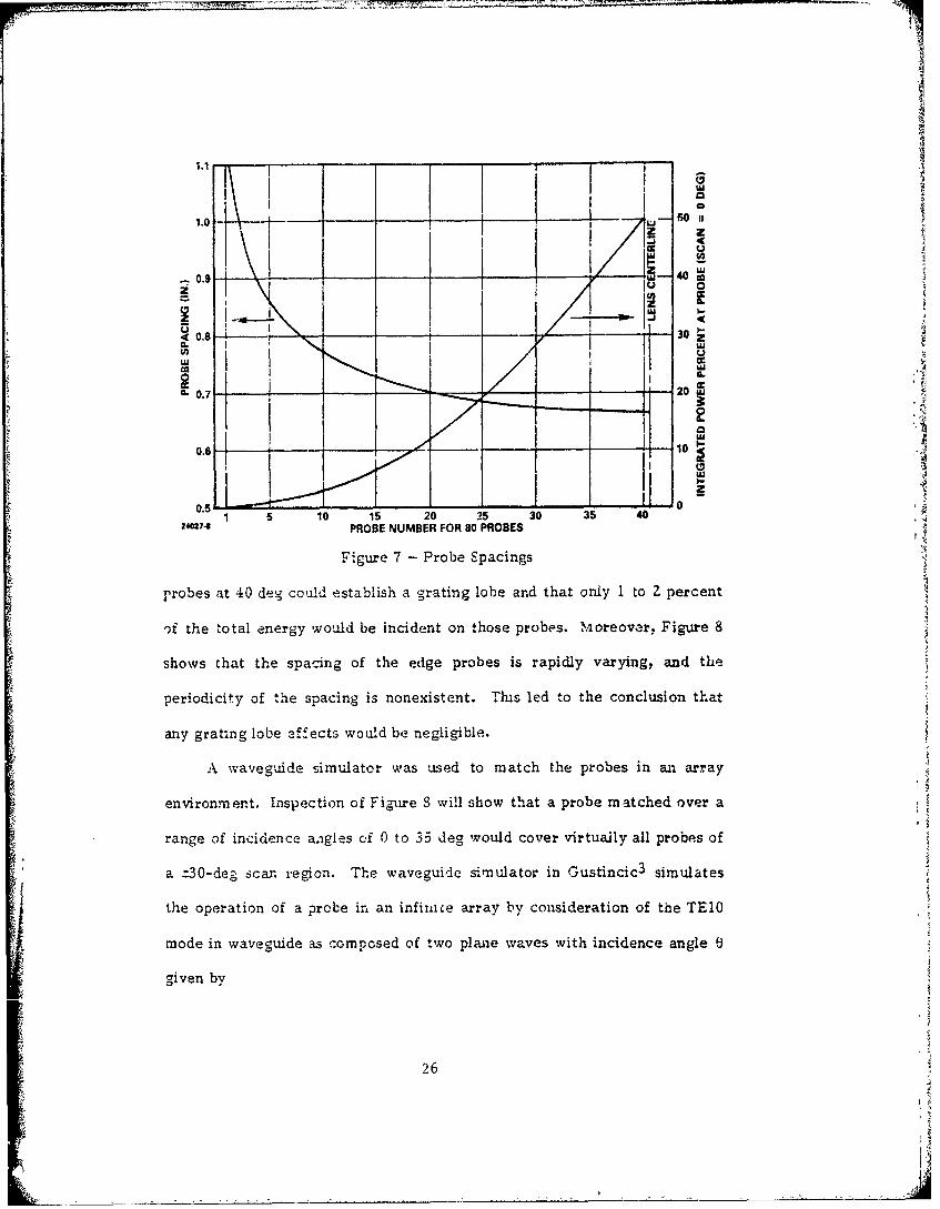
from the centerline. The spacings for this design are shown in Figure 7.
Large spacings on the edge probes can lead to a grating lobe being
generated internally in the parallel plate region which would degrade the
radiated pattern and gain data. The incidence angle at which the grating
lobe will enter visibile space is
e. = sin , (1)
where S is the average spacing to the adjacent probes.
Incidence angles between each probe and the horn are shown in
Figure 8 for four scan angles. The use of this data and Equation (1) estab-
lished that no more than for probes up to a scan angle of 30 deg and six
25
1.0 4O II
z
.7 I
1C 0. 30 "5 2 2 0 5
0
0.720U
240274 PROBE NUMBER FOR S0 PROBES
Figure 7 - Probe Spacings
probes at 40 deg could establish a g=rating lobe and that only 1 to 2 percent
of the total energy would be incident on those probes. ,Moreover, Figure 8
shows that the spacidng of the edge probes is rapidly varying, and the
periodicity of the spacing is nonexistent. Tis led to the conclusion that
any grating lobe effects would be negligible.
-A waveguide simulator was used to match the probes in an array
environment. Inspection of Figure S will show that a probe matched over a
range of incidence angles of 0 to 35 deg would cover virtually all probes of
a t30-deg sca region. Th e weiden mulator in o ustincic3 simulates
the operation of a probe in an infixice array by consideration of the TElO
mode in waveguide as composed of two plane waves with incidence angle
given by
26
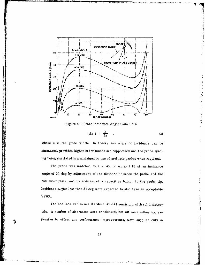
PROBE
INCIDENCE ANGLEISCAN ANGLE
10 40 50D0E0G
FROMHR PHASE CENTERus ' oDEG , ._30 30
+ 15 DEG
200 DEG
Figure 8 - Probe Incidence Angle from Horn0x
sin 6 (Z)
where a is the guide width. In theory any angle of incidence can be
simulated, provided higher order modes are suppressed and the probe spac-
ing being simulated is maintained by use of multiple probes when required.
The probe was matched to a VSWR of under 1.10 at an incidence
angle of 31 deg by adjustment of the distance between the probe and the
end short plate, and by addition of a capacitive button to the probe tip.
Incidence a..-les less than 31 deg were expected to also have an acceptable
VSWR.
The bootlace cables are standard UT-141 semirigid with solid dielec-
tric. A number of alternates were considered, but all were either too ex-
pensive to offset any performance improvements, were supplied only in
27

precut lengths with connectors attached, or did not exhibit good phase
stability during environmental testing.
Good phase stability in the selected cable was achieved by an initial
heating of the cables to an elevated temperaure, trimming off the extruded
teflon, and attachment of the SMA connectors. Additional tests over a
wide range of temperatures demonstrated that the cable phase could be
controlled to better than 3 deg using this technique.
4.2.3 Lens Folding - A major obstacle to be overcome in the implementa-
tion of the lens fed array was accommodation of the parallel plate propa-
gation region within the antenna envelope, For acceptable phase deviation
and scan angle results, a lens F/D 0.7 was required, which posed a space
factor problem. The most acceptable soluion to this problem was tc told
the parallel plates. However, the bend introduced by folding creates a
phase shift which will be dependent on the angle of incidence, ei, at the
bend. Because 3. will be both probe number and scan angle dependent,
compensation will be difficult. Calculations showed that, for a ±30-deg
scan, 9. will vary from 0 to 30 deg for probes near the lens center, and
from 30 to 70 deg for edge probes. The largest differential change is on
the order of 40 deg.
Computation of the phase shift was made by two methods. The first~4
used equations in Marcuvitz for an E-plane waveguide bend, with changes
in e. made by adjustment of the waveguide width. The second method1
(Balbar-) reaqdred sol'ing the wave equation in cylindrical coordinates.
28
!IV

Because the bend angle can assume any angle, the solution requires Hankel
functions of real, non-integer order.
The two solutions are compared in Figure 9 for a 180-deg E-bend
with a 1-in. centerline bend radius and 0.5-in. plate separation. The agree-
4ment is well within acceptable tolerances, and Marcuvitz equations were
subsequently incorporated into the lens design computer program.
Several approaches to fabricating the folded parallel plates were
investigated. The approach which best met the requirements of low
weight, low propagation loss, structural integrity and intraplate alignment
without intraplate support, was a precision assembly of 10 -*uminum nu-
merically-controlled machinings. Alignment is controlled through the inner
0 CENTERLINE RADIUS = 1.0 IN.
9 PLATE SEPARATION = 0.5 IN.
0 -MARCUVITZ: WAVEGUIDE7X41 I HANDBOOK (PP 333-3341
COMPLETE MODAL SOUTION
- -- J , ' -. ------I I * I _I
0
10 20 30 40 50 60 70 s024021.10 ANGLE OF INCIDENCE (DEG)
Figure 9 - Phase Shift Difference Between Unfolded and
Folded Parallel Plate at 180-Deg E-Plane Bend
29

and outer bend sections and the end caps which tie them together. The flat
plate sections bolt to the bends with close tolerance tongue and groove
joints ensuring alignment. An optimum balance between wei$ t'and struc-
tural integrity was achieved by machining a quilted pattern on the outer
surfaces, thereby incorporating integral structural stiffeners. Plate thick-
ness between the structural stiffeners was reduced to O.OZO to 0.030 in.
4.2.4 Feed Horn - A conventional H-plane flared horn with a Z- by 0.4-in.
aperture was used as the lens feed. Quarter-wave chokes were used to
reduce radio frequency (RF) breakdown potential between the horn and the
parallel plates. Teflon buttons on both top and bottom of the horn worked
as a low-friction contact and centering mechanism between the plates.
Initial lens calculations used a theoretical H-plane horn pattern.
Aster selection of the 2-in. aperture was made, a number of horn patterns
were measured in a parallel plate and used to further refine the calculated
performance.
Feed horn positioning required special attention. A search for a suit-
able mean~s of positicn sensing led to a device known as the Inductosyn,
manufactured by Farrand Controls. The Inductosyn provides highly precise
linear position sensing and permits the position sensing to be accomplished
directly at the feed horn. The Inductosyn consists of a stationary printed
circuit approximately 0.5-in. wide extending the length of the feed horn
track, a sensing element which mounts to the feed horn, and remote
electronics. The overall closed loop horn positioning accuracy is on the
order of ±O.004 in., which is equivalent to a worst-case angular uncertainty
30
of ±1 arc minute (0.017 deg). The Inductosyn was chosen over comparal. le
optical sensors because of its tolerance to accumulated surface contami-
nants as well as its tolerance to wide temperature excursions.
Another aspect of the feed horn positioning problem is the design of a
transmission line connection between the roll axis rotary joint (the antenna
system input) and the feed horn which is capable of accommodating the
wide range of feed horn motion. High power handling capability, low loss,
and reliability were the governing design considerations. The approach
followed which produced excellent results was an articulating waveguide
assembly made up of two movable waveguide sections connected to each
other and to the horn and stationary input waveguide by three rotary joints.
The feed horn mounts to a hardened V-groove track via rollers. The
feed horn track is concentric with the focal arc and is positioned so that
the feed horn phase center falls on the focal arc. The feed horn is
positioned by a servoloop consisting of a steel tape drive band connected to
a DC torque motor with the Inductosyn providing the loop error signal. The
loop electronics are contained in a separate antenna control unit located
remote from the antenna.
4.3 Array Design -
4.3.1 Waveguide Radiator - The radiator is an open-ended waveguide. The
dimensions are shown in Figure 10 and were analyzed using Diamond's6
infinite array analy-is. The computed E-plane scan admittance normalized
to the waveguide is also shown in Figure 10.
31

(A) SINGLE CELL DIMENSIONS (8) WAVEGUIDE INPUT ADMITTANCE
1• ;..' n ' F o-., .: , ,
ioI / i i-- ..,. -•":'.' ,V
0JlDEG00 .'10 DEGY
IN.
IN SCN ANGLE,30 DEG - EPLANE
-- 40DEG -
,., ,.- ~ ~~IN. '-- "- " ~
Figure 10 -- Waveguide Infinite Array Admittance I
4.3.2 Vertical Radiating Assembly - Selection and design of the vertical
radiating assemb!y involved a significant part of the total antenna design
*ffcrt. Because the antenna contained 80 of the assemblies, weight and
tcal cost of the design would be critical to overall antenna success. In
addition, total insertion loss must albo be minimized.
Each vertical assembly contained Z0 open-ended waveguide radiators,
an airstrip power divider with an integral stripline to waveguide transition,
a three-way stripline mechanical switch, and the coax to stripline input
connector. The assembly is shown in exploded form, minus the airstrip-to-
switch card finger contacts, in Figure 11.
Mechanical design of the array addressed several objectives. It was
desired that the array have inherent structural integrity and that it con-
triblute to the basic structural stiffness of the entire antenna assembly with
32

P11.
2407-12
Figure 11 - Vertical Power Divider Assembly
a minimum ol additional structure. Assembly of the array should be
straightforward with a minimum of fixturing or specialized alignment and
fitting techniques. Weight and cost were to be minimized.
The answer to these objectives was found to lie in the design of a
three-sided, thin-walled aluminum extrusion with an interlocking edge
design. The open-ended waveguide elements are formed by dip brazing
aluminum partitions into the extrusion at appropriate intervals to provide a
single vertical element of the array. The interlocking edge feature satis-
fies the ease of assembly criterion and contributes to the goal of inherent
structural integrity. Low cost and weight are inherent in the use of an
extrusion.
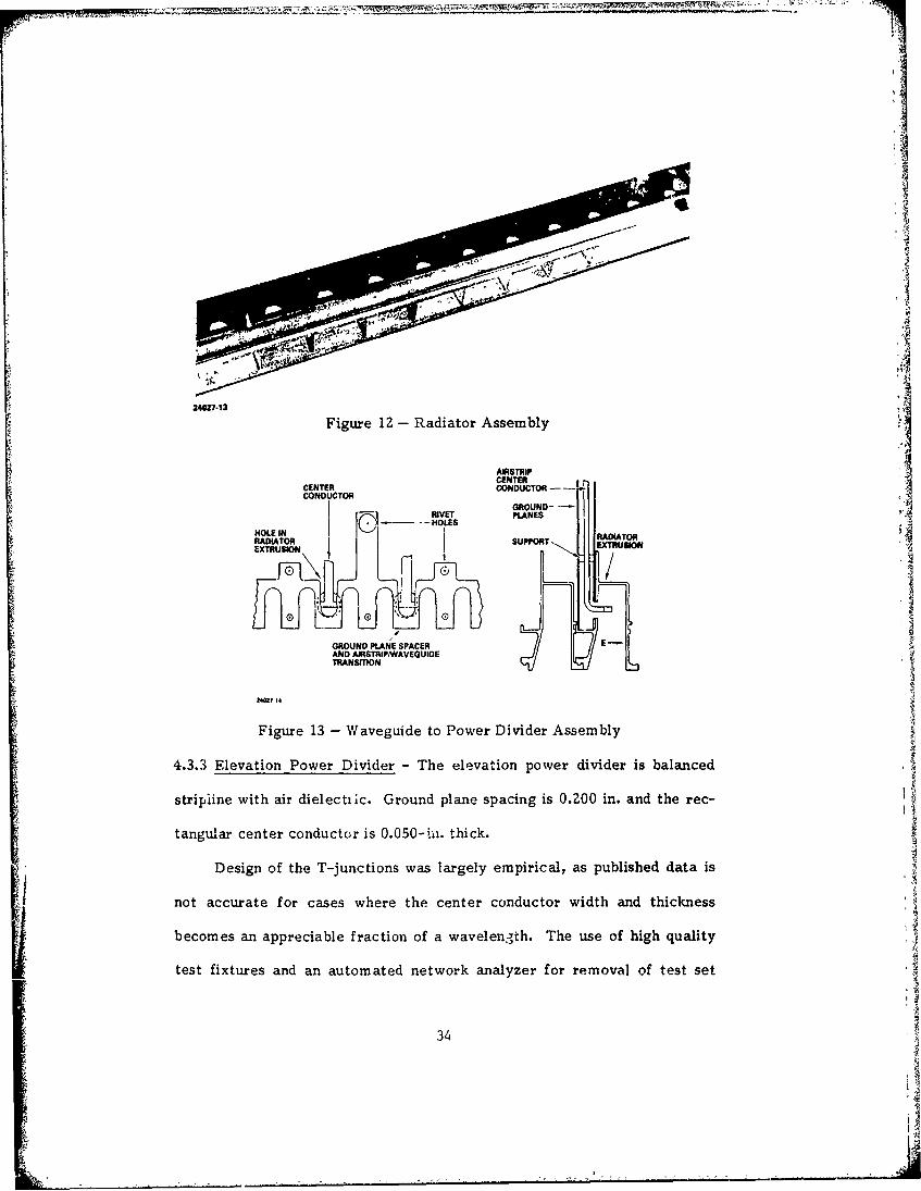
A waveguide assembly, including partitions and holes drilled for
alignment, assembly, and the waveguide-to-stripline transition is shown in
Figure 12. Mechanical relationship of adjoining extrusions, waveguide-to-
stripline transition, and spacer is shown in Figure 13. ie
33
i ,,
4,.-- ---------.- ,---?- -
I.i
24027-13
Figure lZ - Radiator Assembly
AIRSTRIPCENTER
CENTER CONDUCTOR - - -CONDUCTOR
GROUND-RIVET PLANES
HOLE IN _HLRAEIATORRADIATOR SU 'OT RDITO
EX goo SEXTRUSION
GROUND PLANE SPACER EAND AIRSTRIPWAVEGUIDETRANSITION
24M7 14
Figure 13 - Waveguide to Power Divider Assembly
4.3.3 Elevation Power Divider - The elevation power divider is balanced
stripiine with air dielectiic. Ground plane spacing is 0.200 in. and the rec-
tangular center conductor is 0.050-ii. thick.
Design of the T-junctions was largely empirical, as published data is
not accurate for cases where the center conductor width and thickness
becomes an appreciable fraction of a wavelen-,th. The use of high quality
test fixtures and an automated network analyzer for removal of test set
34
errors was found to be essential. In addition, all dimensions established in
the laboratory had to be checked using end mills and cutters representative
of those to be used in production, to optimize performance on a unit-to-
unit basis.
The center conductor is supported by nylon spacers with a small pin
through the center conductor. The capacitive effect of the pin was com-
pensated for by a reduction in the conductor width over a total length of
approximately X/4. The number and location of the standoffs was based
upon a vibration analysis and an allowable deviation of the center conduc-
tor from a centered location between the ground planes.
The stripline to waveguide transition is an integral part of the strip-
lire. After machining, the T-shaped adapter is bent at a right angle and
inserted through a hole in the waveguide wall. A spacer bar both spaces
the ground planes and provides a square coax section in the vicinity of the
transition to suppress higher order modes.
Measured VSWR of a 16-port power divider, including the stripline to
waveguide transition, is shown in Figure 14. Similar data was obtained on
the four-port divider.
4.3.4 Elevation Beam Switch - A mechanically movable stripline card is
used to select one of three elevation beams. Contact between the card and
the power divider center conductor is through beryllium copper fingers.
A torque motor and shaft is used to actuate the switches. A lever
arm connects each card to the shaft, and the card is constrained in lateral
movement by nylon rollers located between the ground planes.
35

4V
24027-15
Figure 14 - Sixteen-Port Power Divider Admittance
The beryllium copper fingers represented a significant experimental
design effort to realize a design capable of maintaining contact over board
variations in thickness, warpage, and deflections, while at the same time
providing 4cceptable VSWR and insertion loss at an acceptable manufactur-
ing price.
Measured VSWIR of the switch card, including fingers and airstrip
support posts located next to the card, was under 1.15 in all positions.
An additional factor was the angular positional accuracy of the card
relativre to the fingers. Tests showed that misalignment of ±0.020 In. was
acceptable.
36
To date the switches have been actuated several hundred times with
no evidence of degradation. This has included operation during an environ-
mental test simulating a typical aircraft pod.
4.3.5 Pressure Cylinder - A requirement for pressurization is imposed by
transmitter peak power levels and operation in an unpressurized pod at high
altitudes. The impracticality of pressurizing the basic antenna is evident
when the problem of sealing the feed horn access to the parallel plate
region is addressed. Pressure containment was achieved by enclosing the
antenna in a thin-wall composite cylinder having good microwave transmis-
sion as well as excellent structural and temperature properties.
5. ANTENNA PERFORMANCE
This antenna was tested on a 2250-ft range. Both transmit and test
antennas are about 35 ft above flat terrain. The range has been used for
production X-band antenna testing for about eight years, and has measured
amplitude ripples over a 4-ft-high by 8-ft-wide aperture of 0.5 dB
maximurn.
Peak azimuth sidelobes for three frequencies and a scan angle of +38
to -30 deg are shown in Figure 15 for the 20-port switch position. Very
similar data was measured for the 16-port and four-port positions.
Antenna gain loss, measured at the feed horn for zero-deg scan,
ranged from -Z.4 to -3.0 dB, relative to the theoretical aperture gain. An
additional 0.9 dB of loss occurred in three azimuth and one roll axis rotary
joints, and over 5 ft of connecting waveguide. Typically, scanning to
I30 deg introduced an additional 0.5 dB of loss, with 0.7 dB at 38 deg.
37
,-\
-16
- I
S24- SO RIGHT
~28-30 -20 -10 0 10 20 30
AZIMUTH SCAN ANGLE (DEG)
F0 + 60 MHZ ___-__0___
6 LEFT LEF
~20 L2
~24RIH0 ~~~RIGHT ~2 J 1L L
-30 -20 -10 0 10 20 30 -30 -20 -10 0 10 20 30AZIMUTH SCAN ANGLE (DEG) AZIMUTH SCAN ANGLE (DEG)
Figure 15 - Peak Azimuth Sidelobes
Typical azimuth and elevation patterns are shown in Figures 16
<I through 22. A full ±90-deg azimuth cut is shown in Figure 22. Overall
falloff of the iobes is excellent out to about 45 deg, but relatively high
lobes are present in the 45- to 70-deg region. These lobes vary in ampli-
was not established, but could be due to an illumination error over the lens
probes orLoreflections caused by extraneous structure arcund the antenna
Becase aRotman lens is a w.ideband device, data was measured -it a
frequency 10 percent above the center design frequency. Despite known .
mismatches in the elevation power divider, the beam switch, and the lens,
no azimuth or elevation pattern degradations were measured. More
impDortantly, little or no change in beamn position was measured, further
confirming the suitability of a lens as a wideband, widescan antenna.
38

10..!
20 1
-2- -20 -15 -10 -5 0 5 10 15 20 25
214Ca.17
Figure 16 - Zero-Deg Scan, Frequency = Fo, Azimuth Cut
20-. ---- -
2-30- 0 1 - 0 5 1
30 -25 -2 1 1 5 0 5 10 15 20 25 30
Figure 17 - Zero-Deg Scan, Frequency =F, Elevation Cut
t0
R ill
39

0 -, ____,,_- .............. .. ..... . - f-,- -.
40 L- A A A
I
Io iI
0 5 10 15 20 25 30 35 40 4( 50 55 60
24027.1 AFigure 18 - Thirty-Deg Scan, Frequency = Fo, Azimuth Cut
° I i , i I - ---1
40 I
Fiur 19 - 4.ryD gS aF eue c lvto u
' ii II
30 I----fi
4 I
0-30 -25 -20 -15 -10 - 0 5 10 15 20 25 30
i Figure 19 - Thirty-Deg Scan, Frequency/ F0 , Elevation Cut
40 °
-J

101
441
JO
Is I I
i I20 -I
I II
S1 25I
-90 -60 -30 0 30 60 90
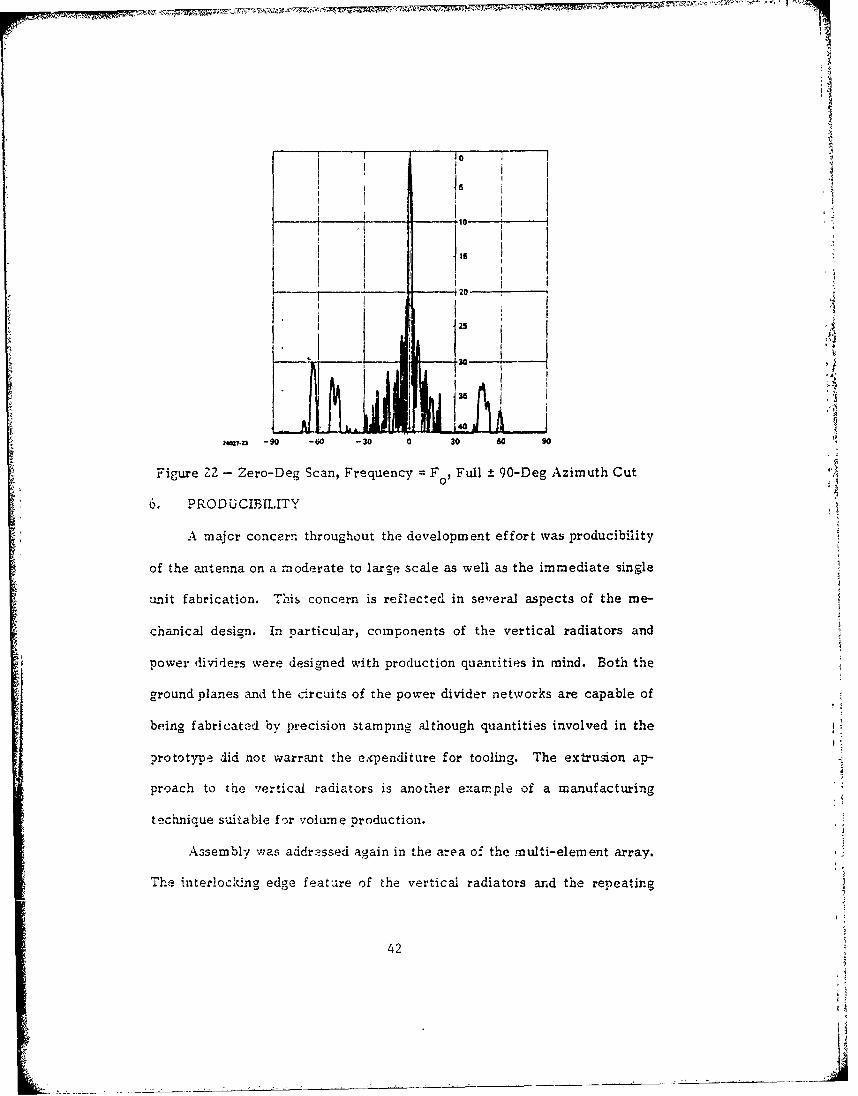
Figure N - Zero-Deg Scan, Frequency = Fo, Full - 90-Deg Azimuth Cut
6. PRODUCIBILITY
A major concern throughout the development effort was producibility
of the antenna on a moderate to large scale as well as the immediate single
unit fabrication. This concern is reflected in se'?eral aspects of the me-
chanical design. In particular, components of the vertical radiators and
power dividers were designed with production quantities in mind. Both the
ground planes and the circuits of the power divider networks are capable of
being fabricated by precision stamping ailthough quantities involved in the
prototype did not warrant the expenditure for tooling. The extrusion ap-
proach to the vertical radiators is another example of a manufacturing
technique suitable for volume production.
Assembly was addressed again in the area of the multi-element array.
The interlocking edge feature of the vertical radiators and the repeating
42

2hiiplanar nature of the power dividers both contributed to a simple stacking
assembly procedure which did not rely on complex fixturing or highly
skilled personnel.
7. SUMMARY
This paper has described a wideband, wide scan antenna with applica-
tion to pod-mounted reconnaissance radars. A folded lens as a perform-
ance effective alternate to a phase shifter scanned array has been demon-
strated. A key to the overall success of the antenna was a philosophy
which emphasized minimal weight, producibility, and suitability for produc-
tion during all stages of development. The design is expected to be readily
adaptable to specific program requirements.
8. ACKNOWLEDGEMENTS
A number of people contrib, -d to the success of this antenna by
contributing ideas, moral support, and hard work. In particular,
W.C. Woody provided invaluable ideas and concepts for the overall antenna
design; W.O. Klever served as project lead engineer; H.A. Burger developed
the vertical power divider and switch; A.C. Brown, Jr. provided the parallel ?
plate bend and probe analysis; B.W. McIntyre provided a consistently high
level of laboratory data; and R.E. Meyer led the mechanical design team
and shepherded the antenna through the fabrication, assembly, and test
phases. Their contributions are gratefully acknowledged.
AII
43

REFERENCES
1. R~ize, J. (1950) Wide-angle metal-plate optics, Proc. IRE Vol 38:53.
2. Rotman, W. and Turner, R.F. (1963) Wide-angle microwave lens for
line source applications, IEEE Trans. Vol AP-1l:6Z3.
3. Gustincic, J.J. (1972) The determination of active array impedance
with multielement waveguide simulators, IEEE Trans.
Vol AP-20:589.
4. Marcuvitz, N. (1950) Waveguide Handbook, McGraw-Hill, New York,
p 333.
5. Bahar, E. (1969) Fields in waveguide bands expressed in terms of
coupled local annular waveguide modes, IEEE Trans.-
,MTT, Vol 17:210, 36. Diamond, 3.L. 0i9o8) A generalized approach to the analysis of
infi.nite planar arrav antennas, Proc. IEEE Vol 56:1837.
444
5