essentials computer desk
TRANSCRIPT
The original desktop.
Essentials Computer DeskModel 5424256
Teknik www.teknikoffice.co.uk

Part Identifi cation
Hardware Identifi cation
Assembly Steps
Français
Español
Safety
Warranty
HammerNot actual size
No. 2 Phillips ScrewdriverTip Shown Actual Size
Skip the power trip.This time.
Table of Contents Assembly Tools Required
3
4
5-28
29-32
33-36
37-38
39
Page 2

Part Identifi cation
å While not all parts are labeled, some of the parts will have a label or an inked letter on the edge to help distinguish similar parts from each other. Use this part identifi cation to help identify similar parts.
Now you knowour ABCs.
V RIGHT END (1)
W LEFT END (1)
X UPRIGHT (1)
Y TOP (1)
Z MODESTY PANEL (1)
AA BACK (1)
BB SHELF (1)
CC ADJUSTABLE SHELF (1)
DD BOTTOM (1)
EE SKIRT (1)
FF DOOR (1)
GG KEYBOARD SIDE (2)
HH KEYBOARD BACK (1)
JJ KEYBOARD SHELF (1)
KK KEYBOARD FRONT (1)
LL LEFT DRAWER SIDE (1)
MM DRAWER BACK (1)
NN RIGHT DRAWER SIDE (1)
OO DRAWER BOTTOM (1)
PP DRAWER FRONT (1)
V
W
X
Y
Z
AA
BB
CC
DD
EE
FF
GG
GG
HH
JJKK LL
MM NN
OO
PP
Page 3
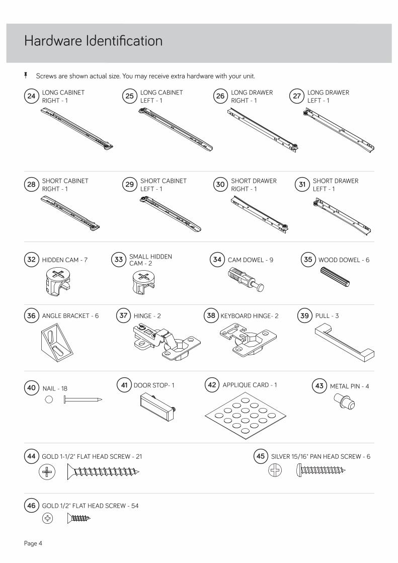
Hardware Identifi cation
å Screws are shown actual size. You may receive extra hardware with your unit.
GOLD 1-1/2" FLAT HEAD SCREW - 2144
HIDDEN CAM - 732 CAM DOWEL - 934 WOOD DOWEL - 635SMALL HIDDENCAM - 233
LONG DRAWER LEFT - 1
27LONG DRAWER RIGHT - 1
26
SHORT DRAWER LEFT - 1
31SHORT DRAWER RIGHT - 1
30SHORT CABINET RIGHT - 1
28
ANGLE BRACKET - 636 KEYBOARD HINGE- 23837 HINGE - 2 PULL - 339
METAL PIN - 443DOOR STOP- 141NAIL - 1840 APPLIQUE CARD - 142
GOLD 1/2" FLAT HEAD SCREW - 5446
SILVER 15/16" PAN HEAD SCREW - 645
LONG CABINET RIGHT - 1
24 LONG CABINET LEFT - 1
25
SHORT CABINET LEFT - 1
29
Page 4

HOW TO USE A HIDDEN CAM & CAM DOWEL
Hidden CamHidden Cam
Arrow
Push a HIDDEN CAM into the part. The arrow in the HIDDEN CAM must point toward the hole in the edge of the board.
Hole
Cam Dowel
Gently tap a CAM DOWEL into the part.
Insert the CAM DOWEL into the HIDDEN CAM. Tighten the HIDDEN CAM.
1
2
Hardware Usage Guide
Page 5

å Push two HIDDEN CAMS (32) into the UPRIGHT (X).
å Push the DOOR STOP (41) into the holes in the UPRIGHT (X).
å Fasten the LONG CABINET LEFT (25) to the UPRIGHT (X). Use four GOLD 1/2" FLAT HEAD SCREWS (46).
å Flip the UPRIGHT (X) over. Fasten the SHORT CABINET RIGHT (28) to the UPRIGHT (X). Use three GOLD 1/2" FLATHEAD SCREWS (46).
Step 1
Arrow
The arrow in the HIDDEN CAM must point toward the hole in the edge of the board.
Hole
GOLD 1/2" FLAT HEAD SCREW(7 used in this step)
46
Use the 1st, 5th, 7th and 11th hole from the roller end of the LONG CABINET LEFT (25).
Use the 1st, 5th, and 11th
hole from the roller end of the SHORT CABINET RIGHT (28).
Roller end
Roller end
CL
CR
FLIP OVER
41
28
25
X
X
Arrow
32
(2 used)
The large hole must be here.
Page 6

å Push four HIDDEN CAMS (32) into the ENDS (V and W).
å Fasten the LONG CABINET RIGHT (24) to the RIGHT END (V). Use four GOLD 1/2" FLAT HEAD SCREWS (46).
å Fasten the SHORT CABINET LEFT (29) to the LEFT END (W). Use three GOLD 1/2" FLAT HEAD SCREWS (46).
Step 2
32
Arrow
Arrow
The arrow in the HIDDEN CAM must point toward the hole in the edge of the board.
Hole
(4 used)
V
W
24
29
GOLD 1/2" FLAT HEAD SCREW(7 used in this step)
46
These holes must be here.
Roller end
Use the 1st, 5th, 7th and 11th hole from the roller end of the LONG CABINET RIGHT (24).
Use the 1st, 5th, and 11th
hole from the roller end of the SHORT CABINET LEFT (29).
Roller end
CL
CR
Page 7

Step 3
å Fasten six ANGLE BRACKETS (36) to the SHELF (BB),BOTTOM (DD), and SKIRT (EE). Use six GOLD 1/2" FLAT HEAD SCREWS (46).
å NOTE: Be sure the edges of the ANGLE BRACKETS areeven with the edges of the SHELF, BOTTOM and SKIRT.
å Insert four WOOD DOWELS (35) into the holes in the edgesof the KEYBOARD BACK (HH) and SHELF (BB) as shown.
EE
DD
BB
HH
35
353535
36
36
36
36
Unfi nished surface
Unfi nished surface
Unfi nished surface
Page 8
Some assembly (and snacks) required.
GOLD 1/2" FLAT HEAD SCREW(6 used for the ANGLE BRACKETS)
46

å Push the HIDDEN CAM (32) into the MODESTY PANEL (Z).
å Fasten the UPRIGHT (X) and LEFT END (W) to SHELF (BB)and MODESTY PANEL (Z). Use seven GOLD 1-1/2" FLAT HEAD SCREWS (44).
å NOTE: Be sure the WOOD DOWELS in the SHELF insert intothe UPRIGHT and LEFT END.
å Fasten the SHELF (BB) to the MODESTY PANEL (Z). Use twoGOLD 1/2" FLAT HEAD SCREWS (46) through the ANGLE BRACKETS and into the MODESTY PANEL.
Step 4
32
Arrow
Z
X
W
Z
BB
GOLD 1/2" FLAT HEAD SCREW(2 used in this step)
46
GOLD 1-1/2" FLAT HEAD SCREW(7 used in this step)
44
Page 9
Roller end

å Fasten the BOTTOM (DD) to the UPRIGHT (X). Use twoGOLD 1-1/2" FLAT HEAD SCREWS (44).
å Fasten the RIGHT END (V) to the BOTTOM (DD). Use twoGOLD 1-1/2" FLAT HEAD SCREWS (44).
Step 5
GOLD 1-1/2" FLAT HEAD SCREW(4 used in this step)
44
V
XDD
Unfi nished surface
The ANGLE BRACKETS should be here.
Page 10

Step 6
å With a hammer, gently tap nine CAM DOWELS (34) intothe TOP (Y) and DRAWER FRONT (PP).
Y
PP
34
Page 11
(9 used)

Unfi nished surface
Step 7
å Fasten the TOP (Y) to the ENDS (V and W), UPRIGHT (X), andMODESTY PANEL (Z). Tighten seven HIDDEN CAMS.
V
X
Z
Y
W
Page 12

6"1/4"
Step 8
å Carefully turn your unit over onto its front edges.
å Make equal margins along all four edges of the BACK (AA).
å Fasten the BACK (AA) to your unit using the NAILS (40).The NAILS should be 6" apart and 1/4" in from the edges.
NAIL(16 used in this step)
40
AA
Page 13
Side Step: Make nachos. (Optional, but recommended.)
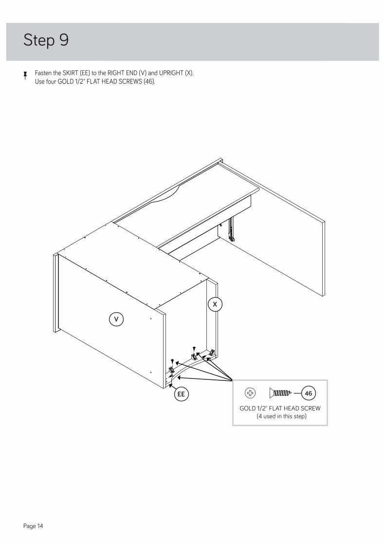
Step 9
V
X
GOLD 1/2" FLAT HEAD SCREW(4 used in this step)
46EE
å Fasten the SKIRT (EE) to the RIGHT END (V) and UPRIGHT (X).Use four GOLD 1/2" FLAT HEAD SCREWS (46).
Page 14

å Fasten the KEYBOARD SIDES (GG) to theKEYBOARD BACK (HH). Use two GOLD 1-1/2" FLAT HEAD SCREWS (44).
Step 10
Finished surface
Wood dowels
Edge with holes
Edge with holes
GOLD 1-1/2" FLAT HEAD SCREW(2 used in this step)
44
GOLD 1-1/2" FLAT HEAD SCREW
44
GG
HH
GG
Page 15
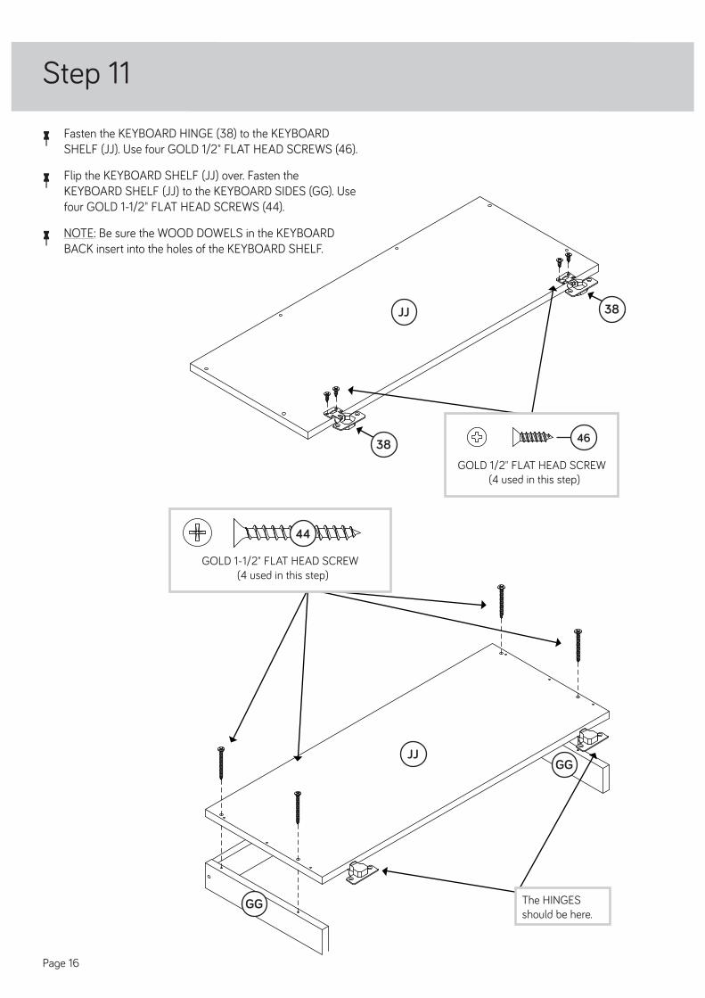
å Fasten the KEYBOARD HINGE (38) to the KEYBOARDSHELF (JJ). Use four GOLD 1/2" FLAT HEAD SCREWS (46).
å Flip the KEYBOARD SHELF (JJ) over. Fasten theKEYBOARD SHELF (JJ) to the KEYBOARD SIDES (GG). Use four GOLD 1-1/2" FLAT HEAD SCREWS (44).
å NOTE: Be sure the WOOD DOWELS in the KEYBOARDBACK insert into the holes of the KEYBOARD SHELF.
Step 11
GOLD 1/2" FLAT HEAD SCREW(4 used in this step)
46
JJ
JJ
GG
GG
GOLD 1-1/2" FLAT HEAD SCREW(4 used in this step)
44
The HINGES should be here.
Page 16
38
38

å Fasten the SHORT DRAWER RIGHT (30) and SHORTDRAWER LEFT (31) to the KEYBOARD SHELF (JJ). Use six GOLD 1/2" FLAT HEAD SCREWS (46).
Step 12
JJ
Roller end
Roller end
GOLD 1/2" FLAT HEAD SCREW(6 used for SHORT DRAWER SLIDES)
46
30
31
Page 17

å Flip the KEYBOARD SHELF (JJ) over. Fasten theKEYBOARD FRONT (KK) to the HINGES on the KEYBOARD SHELF (JJ). Use four GOLD 1/2" FLAT HEAD SCREWS (46).
Step 13
KK
JJ
GOLD 1/2" FLAT HEAD SCREW(4 used in this step)
46
Page 18

å Push two SMALL HIDDEN CAMS (33) into the DRAWERSIDES (LL and NN).
å Insert two WOOD DOWELS (35) into the short edges ofthe DRAWER SIDES (LL and NN).
Step 14
NN
LL
35
35
Arrow
33
Arrow33
Page 19

Step 15
å Fasten the DRAWER BACK (MM) to the DRAWER SIDES (LL and NN). Use four GOLD 1-1/2" FLAT HEAD SCREWS (44).
å NOTE: Be sure the DRAWER BOTTOM (OO) inserts into the groove of the DRAWER BACK (MM).
1 2
3
å Fasten the DRAWER SIDES (LL and NN) to theDRAWER FRONT (PP). Tighten two HIDDEN CAMS.
å NOTE: Be sure the WOOD DOWELS in to the DRAWERSIDES insert into the DRAWER FRONT.
å Slide the DRAWER BOTTOM (OO) into the grooves in theDRAWER SIDES (LL and NN) and DRAWER FRONT (PP).
NN
NN
NN
PP
PP
LL
LL
LL
OO
Be sure the DRAWER BOTTOM inserts into the DRAWER BACK groove.
Groove
Be sure the DRAWER BOTTOM inserts into the DRAWER FRONT groove.
With the palm of your hand, tap the DRAWER BOTTOM down into the groove.
Start each screw a few turns before completely tightening any of them.
GOLD 1-1/2" FLAT HEAD SCREW(4 used in this step)
44MM
Page 20
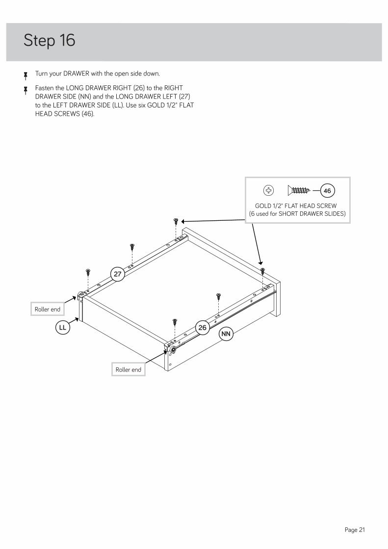
å Turn your DRAWER with the open side down.
å Fasten the LONG DRAWER RIGHT (26) to the RIGHTDRAWER SIDE (NN) and the LONG DRAWER LEFT (27) to the LEFT DRAWER SIDE (LL). Use six GOLD 1/2" FLAT HEAD SCREWS (46).
Step 16
Roller end
Roller end
GOLD 1/2" FLAT HEAD SCREW(6 used for SHORT DRAWER SLIDES)
46
NNLL 26
27
Page 21

å Fasten the PULLS (39) to the KEYBOARD FRONT (KK)and DRAWER FRONT (PP). Use four SILVER 15/16" PAN HEAD SCREWS (45).
Step 17
39
39
KK
PP
SILVER 15/16" PAN HEAD SCREW(4 used for the PULLS)
45
Page 22

Step 18
å Carefully stand your unit upright.
å To insert the drawer into your unit, tip the front of thedrawer down and drop the rollers on the drawer behind the rollers on the unit. Lift the front of the drawer up and slide it into the unit. Repeat this step to insert the KEYBOARD SHELF (JJ).
å Insert the METAL PINS (43) into the hole locations of yourchoice in the RIGHT END (V) and UPRIGHT (X).
Place the roller on the SLIDE behind the roller on the RAIL.
43
43
V
X
Page 23
(4 used)
JJ

WARNINGPlease use your furniture correctly and safely. Improper use can cause safety hazards,or damage to your furniture or household items. Carefully read the following chart.
Look out for: What can happen: How to avoid the problem:
• Overloaded shelves or drawers.• Improper loading can cause the productto be top-heavy.
• Risk of injury.• Top-heavy furniture can tip over.• Overloaded shelves and drawers canbreak.
• Never exceed the weight limits shown inthe instructions.• Work from bottom to top when loadingshelves and drawers. Place the heavier items on the lower shelves or in lower drawers.
• Improperly moving furniture that is notdesigned and equipped with casters.
• Furniture can tip over or break ifimproperly moved.• Physical injury. Furniture can be veryheavy.• Breakage of tops - particularly withdouble pedestal furniture (drawers at both ends).
• Unload shelves and drawers from top tobottom before moving the unit.• Do not push furniture, especially on acarpeted fl oor. Have a friend help you lift the item and set it in place.• Provide support to the center section ofthe top when lifting the furniture.
• Placing TVs on furniture items that arenot designed to support a television is hazardous.
• Risk of injury or death. TVs can be veryheavy. Plus the weight and location of the picture tube tends to make TVs unbalanced and prone to tipping forward.
• This product is not designed to support atelevision.