epoch xt training presentation
TRANSCRIPT

EPOCH XT Training PresentationIntroduction and Basic Operation

2
EPOCH XT
Product Overview

3
EPOCH XT Product Overview The EPOCH XT is the first in a new
generation of Ultrasonic Flaw Detectors from Olympus NDT.
Released in August of 2006, The EPOCH XT has been designed to
set a new standard for flaw detector performance. The XT instrument platform is completely new and unique. The instrument is 100% digital with highly accurate analog signal reproduction, and precise digital filtering.
The EPOCH XT has also been designed to withstand the harsh environments that are common in the NDT field with its rugged design and IP67 environmental rating.

4
EPOCH XT Key Features EN12668-1 Compliant – The EPOCH XT is the only
Olympus NDT Flaw Detector to meet this specification. Case sealed to IP67 – Instrument case is designed to be
completely sealed against water for use in harsh environments
Battery Flexibility – The EPOCH XT can be used with Lithium Ion, Nickel Metal Hydride, or Alkaline C-Cell Batteries
Color Liquid Crystal Display (LCD) – Provides good visibility in a variety of lighting conditions with user selectable color schemes
USB Host and USB Client Ports
5
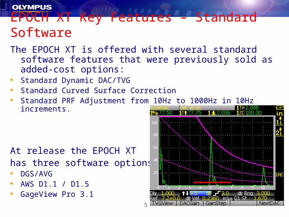
EPOCH XT Key Features – Standard SoftwareThe EPOCH XT is offered with several standard software
features that were previously sold as added-cost options: Standard Dynamic DAC/TVG Standard Curved Surface Correction Standard PRF Adjustment from 10Hz to 1000Hz in 10Hz increments.
At release the EPOCH XT has three software options: DGS/AVG AWS D1.1 / D1.5 GageView Pro 3.1

6
EPOCH XT Key Features – Onboard ReportingThe EPOCH XT allows the
operator to develop inspection
reports on the instrument and
directly print them using the
USB Host connection to a
PCL5 USB printer. Document is .html format All headers can be customized
in the instrument’s datalogger. Each ID in a file is printed on a
separate page.

7
EPOCH XT Key Features – Measurement Flexibility The EPOCH XT can display up to 5 measurements on the live screen Gate 1 and Gate 2 are completely independent unless the operator
chooses to have Gate 2 track Gate 1 (Echo-to-Echo mode). Operator chooses measurements most relevant to his inspection. Available measurements include: Thickness, Soundpath, Surface Distance,
Depth, Min & Max Depth, Amplitude, Min & Max Amplitude, Amplitude to Curve, dB to
Curve, Flat Bottom Hole Size, Overshoot, AWS D1.1 Rating, and Gate 2 – Gate 1

8
EPOCH XT Key Features – Corrosion Thickness Gage Datalogger Files Many customers use EPOCH flaw detectors for thickness surveys for
various reasons. The EPOCH XT datalogger has been designed to make thickness
surveys more convenient by offering all of the file types found in the 37DL PLUS Corrosion Thickness Gage.
File Types: – Incremental– Sequential – Seq. with Custom Pt.– 2D – 2D with Custom Pt. – 2D EPRI– 3D– Boiler

9
EPOCH XT Common Applications + Features
Weld Inspection– Standard DAC/TVG– AWS D1.1 / D1.5 Option– Soundpath Leg Grid Mode– Onboard Reporting– Both gates may be used to take measurements
Forging Inspection– Standard DAC/TVG– TVG Table– Onboard DGS/AVG Option– Keypad adjustable PRF– 500+ inch range– 475V Tunable Square Wave Pulser
Composite Insp.– Tunable square wave pulser with “PerfectSquare” Technology – 475V max pulse energy– Digital Filters– TVG Table
Corrosion Surveys– 37DL+ file types– Large memory capacity– Onboard reporting– File Summary view– Database download to USB drives.
Casting Inspection– Tunable square wave pulser with “PerfectSquare” Technology – 475V max pulse energy– Digital Filters– TVG Table
Boiler Inspection– Superior EMAT performance – 37DL+ file types– Large memory capacity– Onboard reporting– File Summary view– Database download to USB drives.
Thin Materials– “PerfectSquare” technology allows excellent near surface resolution– Spike Mode available– First Peak Measurement Mode– 50V pulse energy setting
Plastic Inspection– Tunable square wave pulser with “PerfectSquare” Technology – 475V max pulse energy– Digital Filters– TVG Table
Capabilities will be further expanded with Phase II development.

10
EPOCH XT
Physical Features

11
EPOCH XT Dimensions
Weight: 4.7 lbs. (2.1kg)* Height: 10.9 in. (277mm) Case Width: 5.5 in. (140mm) Thickness at hand: 2.0 in. (50mm) Thickness at screen: 2.5 in. (63mm)
* Weight with Lithium Ion Battery

12
EPOCH XT Transducer Connections BNC or Large LEMO transducer posts are available at the
same price.– BNC connectors are designed to be sealed to IP67. Caps are
provided to protect unused connector in wet environments– LEMO connectors do not meet IP67. Will be supplied with a protective
rubber cap, but these still must be protected from water.– Standard size LEMO connectors for IP67 are not available but we are
pursuing other connection possibilities.
It is possible to switch connector types, this must be performed at an authorized Olympus NDT service center.

13
EPOCH XT IP67 Environmental RatingThe EPOCH XT is designed to meet the requirements of IP67 This test means that the instrument can be submerged in 3 ft of water for 30
minutes and no liquid will enter the case. This test has been conducted and passed several times. The instruments actually
float and must be weighted down to conduct the test.
HOWEVER ONDT does not recommend that operators
submerge their instrument for any reason. The EPOCH XT is not suitable for use
underwater. ONDT will not cover internal water damage
under warranty in most cases. The IP67 rating is intended to provide a
concrete specification that communicatesthe environmental durability of the instrument. Operators must still use their best judgment before exposing the instrument to a harsh environment.
14
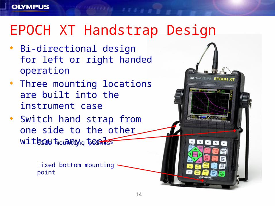
EPOCH XT Handstrap Design Bi-directional design for left or
right handed operation Three mounting locations are
built into the instrument case Switch hand strap from one side
to the other without any tools
Side mounting points
Fixed bottom mounting point

15
EPOCH XT Integrated D-Rings The EPOCH XT has four integrated
D-Ring connectors that allow the use of a chest harness.
The D-Ring mounting locations are extremely rugged.
Removal of D-Rings will not affect the instrument’s seal.
Top D-Rings are mounted at the pipestand mounts.
Bottom D-Rings are mounted at the lower corners of the instrument.

16
EPOCH XT Pipestand DesignThe EPOCH XT has a completely
new pipestand design. Compact Lightweight Durable Simple adjustment – just pull the
stand to the desired position, you do not need to pull or push at the instrument mounting points.
Easily removable

17
EPOCH XT Battery Door Quick release fasteners allow
access to the battery compartment without the use of tools.
Built-in channels hold alkaline C-Cell batteries in place.
Membrane vent sealed with Gore-Tex
TM
to keep moisture out while allowing gases to exit.
18
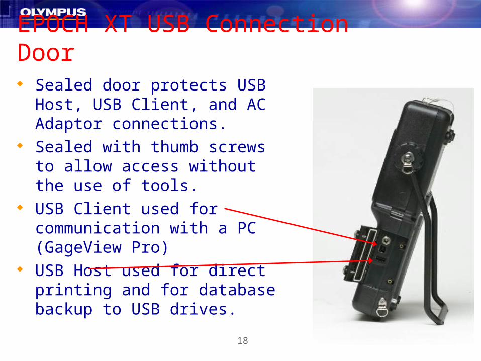
EPOCH XT USB Connection Door Sealed door protects USB Host,
USB Client, and AC Adaptor connections.
Sealed with thumb screws to allow access without the use of tools.
USB Client used for communication with a PC (GageView Pro)
USB Host used for direct printing and for database backup to USB drives.

19
EPOCH XT Optional Hardware I/O The sealed 16 pin Lemo connection on the top of the
EPOCH XT is called the Hardware I/O connection. This connection is an option on all EPOCH XTs. All instruments will ship with this connection at no
additional charge until October 2006. This connection is currently used for Alarm Outputs,
Trigger Input, and Sync Out. Future uses include the instrument’s encoder interface.

20
EPOCH XT
Hardware Design
21
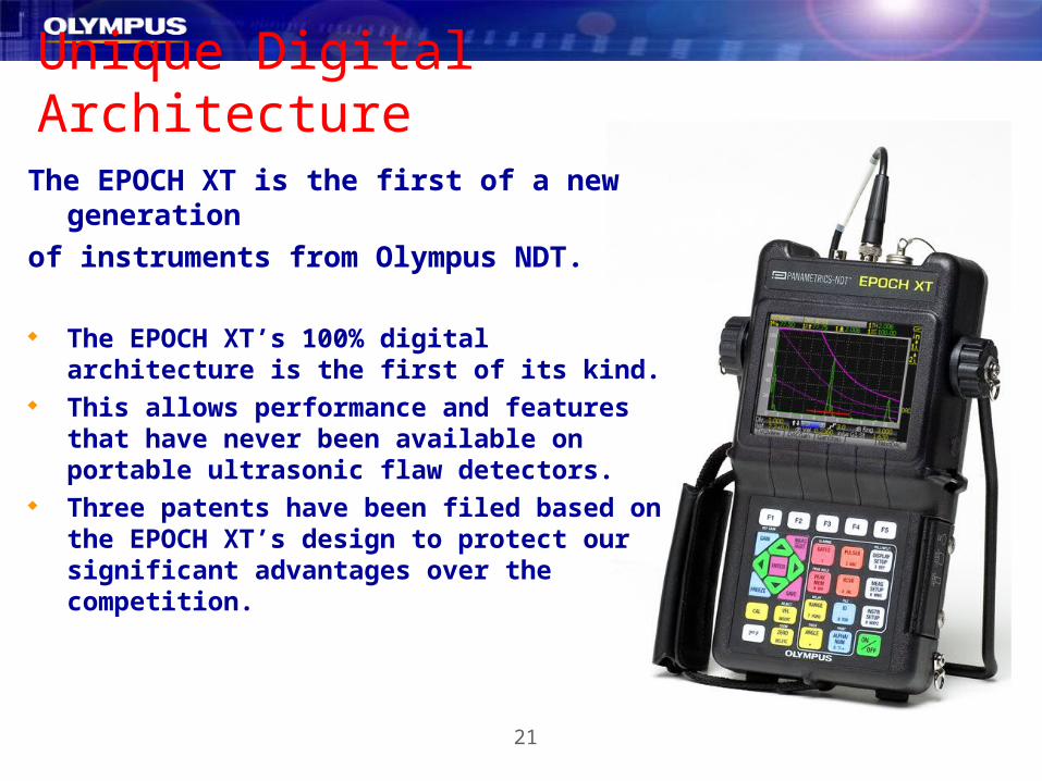
Unique Digital ArchitectureThe EPOCH XT is the first of a new generation
of instruments from Olympus NDT.
The EPOCH XT’s 100% digital architecture is the first of its kind.
This allows performance and features that have never been available on portable ultrasonic flaw detectors.
Three patents have been filed based on the EPOCH XT’s design to protect our significant advantages over the competition.

22
High Dynamic Range Receiver The EPOCH XT’s receiver design allows class leading performance Excellent Signal-to-Noise performance High Dynamic Range (usable gain range)
– Over 100dB for all filter settings
Unique EPOCH XT only features:– Full gain adjustment on frozen waveforms.– Amplitude measurement accuracy of 0.25%– Unprecedented TVG performance with 110dB
of dynamic gain in a setup and 100dB/usec
slopes between points. *depends on filter setting

23
Digital Receiver FiltersDigital Receiver Filters provide many advantages over the analog
filters used in competing equipment and in the EPOCH 4 series.
Advantages include: Highly accurate filter performance Elimination of variability due to components New and/or custom filters can be created
and implemented through software updates.
*This is not going to be a free service. If a
customer is interested we would have to quote
this as an added-cost feature.

24
First Peak MeasurementThe EPOCH XT is has three built in measurement modes: Highest Peak (Peak) Measurement Edge (Flank) Measurement First Peak Measurement
First Peak Measurement measures the first peak in Gate 1 or Gate 2.
This feature is typically used to make accurate thickness
measurements on thin materials.

25
EPOCH XT Keypad Design

26
EPOCH XT KEYPAD (English)5 Function Keys
Three setup menus for display settings, measurements and general instrument preferences.
Region within gray line used for direct alpha-numeric character entry. Active whenever instrument is in “EDIT MODE” or when operator presses [ALPHA/NUM].
Main navigation area is similar to EPOCH 4 series.
27
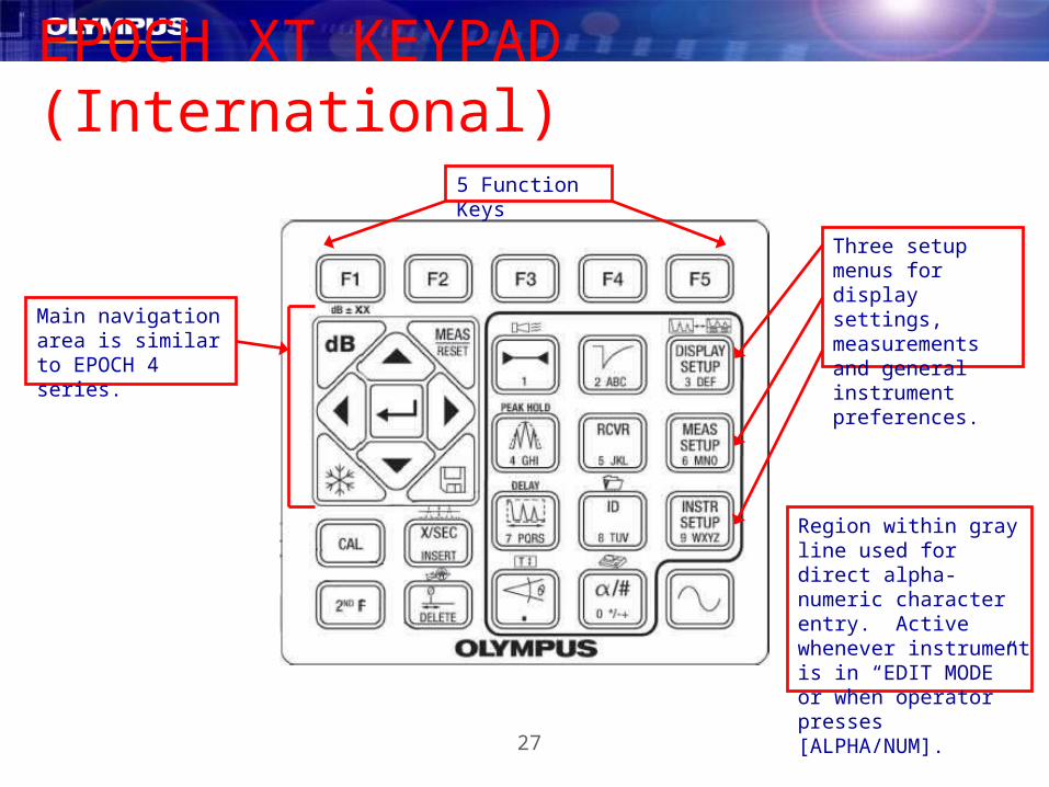
EPOCH XT KEYPAD (International)5 Function Keys
Three setup menus for display settings, measurements and general instrument preferences.
Region within gray line used for direct alpha-numeric character entry. Active whenever instrument is in “EDIT MODE” or when operator presses [ALPHA/NUM].
Main navigation area is similar to EPOCH 4 series.

28
New Keypad FunctionsDirect Entry of Parameter Values: The EPOCH XT keypad has an integrated alphanumeric section. This section is primarily used to enter characters in the instrument’s
datalogger, similar to the EPOCH 4 series. This section may also be used to directly enter
parameter values for rapid adjustment. This is
easily accomplished by following the steps below:1. Press the button for the desired parameter.
2. Press the [Alpha/Num] key.
3. Punch in the value on the keypad.
4. Press [Enter]. To set the GAIN to 55dB, you would press:
29
New Keypad Functions
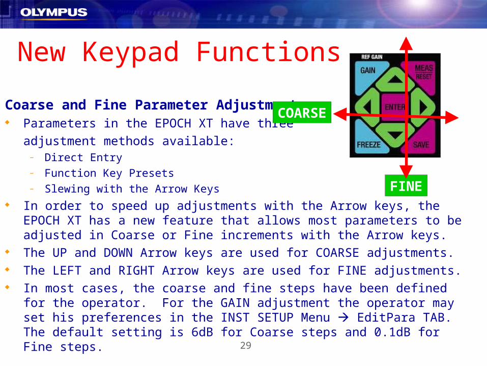
Coarse and Fine Parameter Adjustment Parameters in the EPOCH XT have three
adjustment methods available:– Direct Entry– Function Key Presets– Slewing with the Arrow Keys
In order to speed up adjustments with the Arrow keys, the EPOCH XT has a new feature that allows most parameters to be adjusted in Coarse or Fine increments with the Arrow keys.
The UP and DOWN Arrow keys are used for COARSE adjustments. The LEFT and RIGHT Arrow keys are used for FINE adjustments. In most cases, the coarse and fine steps have been defined for the operator. For
the GAIN adjustment the operator may set his preferences in the INST SETUP Menu EditPara TAB. The default setting is 6dB for Coarse steps and 0.1dB for Fine steps.
FINE
COARSE

30
New Keypad FunctionsDelay Function:
The EPOCH XT has a new Delay function, also known as Display Delay. This function is used to move the time (distance) area that is currently
viewed onscreen without affecting the calibrated zero offset position. This feature has been available on competing instruments for quite awhile,
but the EPOCH’s have only had a ZOOM function available. The EPOCH XT also retains the ZOOM feature for Gate 1.
DELAY

31
New Keypad FunctionsMeas / Reset Function:
The MEAS/RESET function is similar to the same function in Olympus NDT Thickness Gages.
This button is used to exit from menus and return to the live A-Scan measurement screen.
32
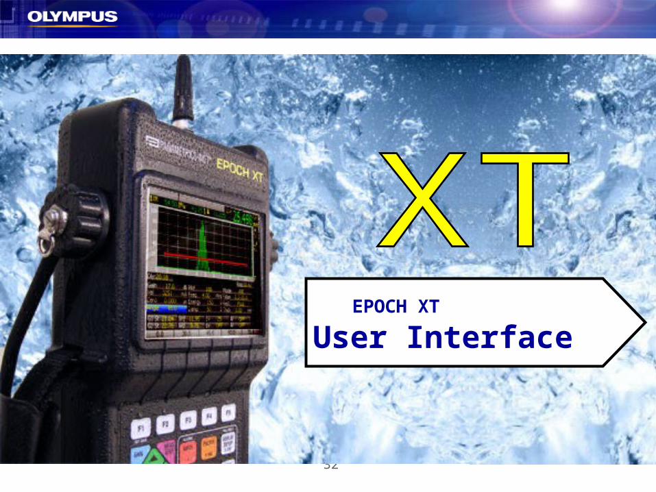
EPOCH XT
User Interface
33
EPOCH XT Software User InterfaceThe EPOCH XT has a completely new software user interface design. Some of the highlights of the new design are listed below:
More modern appearance with better organization of parameters.
Split screen and full screen display modes that are familiar to EPOCH operators
Multiple color schemes to maximize visibility in various lighting conditions
New grid display modes for X and Y axes meet various market needs
5 user customizable measurement locations
New tabbed menu structure similar to MG2 series

34
EPOCH XT Display (Split Screen)
5 Function Presets
4 Measurement Locations
Dual Gate Icons
Battery Indicator
New Delay Setting
PRF Adjustment
File and ID Names
NOTE: The fourth (large) measurement location can be split in half to display the fourth and fifth measurement if activated by the operator.
35
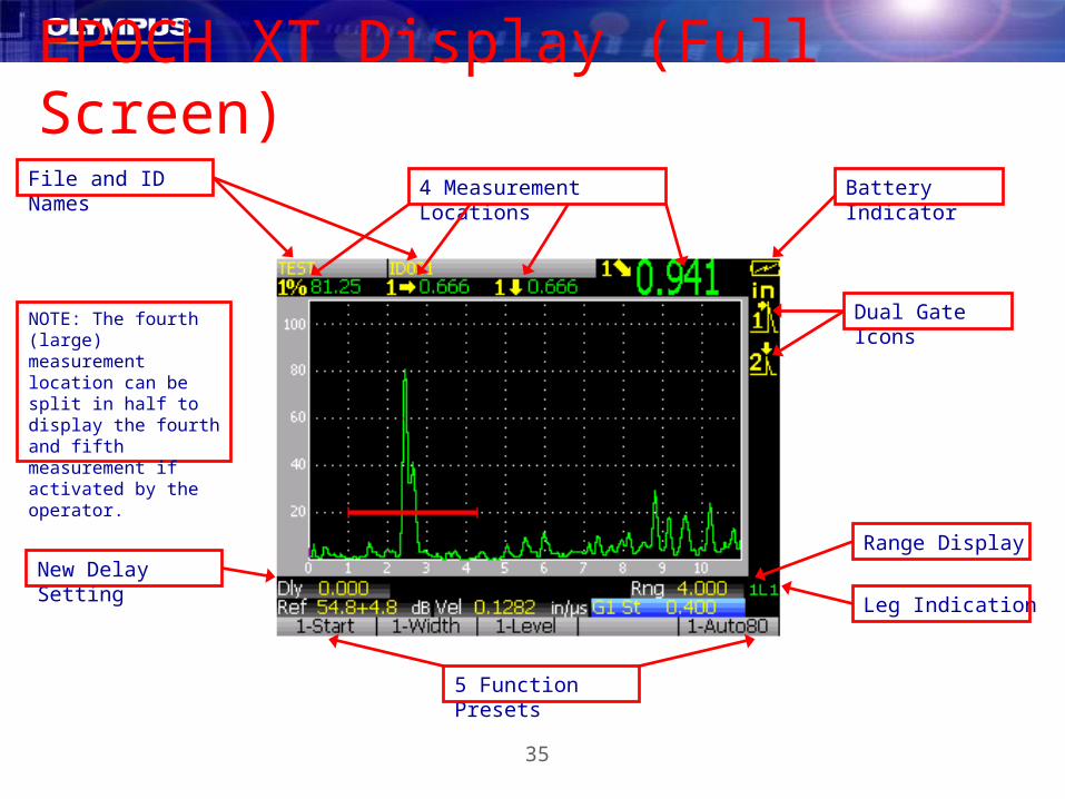
EPOCH XT Display (Full Screen)
5 Function Presets
4 Measurement Locations
Dual Gate Icons
Battery Indicator
New Delay SettingRange Display
Leg Indication
File and ID Names
NOTE: The fourth (large) measurement location can be split in half to display the fourth and fifth measurement if activated by the operator.

36
EPOCH XT Color SchemesThe “Factory” Color Scheme is the default setting for the EPOCH XT.
This color scheme provides excellent indoor visibility. It has been designed to provide color differentiation between parameter labels, settings, and units, and also between measurement icons and the displayed readings.

37
EPOCH XT Color SchemesThe screenshots below show the “Outdoor” Color Scheme.
The “Outdoor” Color Scheme is designed to allow good display visibility in direct sunlight.

38
EPOCH XT Color SchemesThe “ELD” Color Scheme is shown in the screenshots below.
The “ELD” Color Scheme is an alternative to the “Factory” indoor color scheme. This scheme has been designed to be similar to the ELD displays in previous generation equipment with some improvements.
39
EPOCH XT Grid Modes The EPOCH XT’s grid display modes have been enhanced to meet
global market needs and competitive instrument features.
The X-Axis has three display modes: – Standard: 10 equally spaced grid lines. Same as EP4 series– SoundPath: 5 equally spaced grid lines that show sound path
measurements. Based on Delay and Range settings.– Leg: This mode displays up to 5 grid lines labeled LEG1 to LEG5. These
grid lines correspond with the ½ skip distance for your angle beam setup.
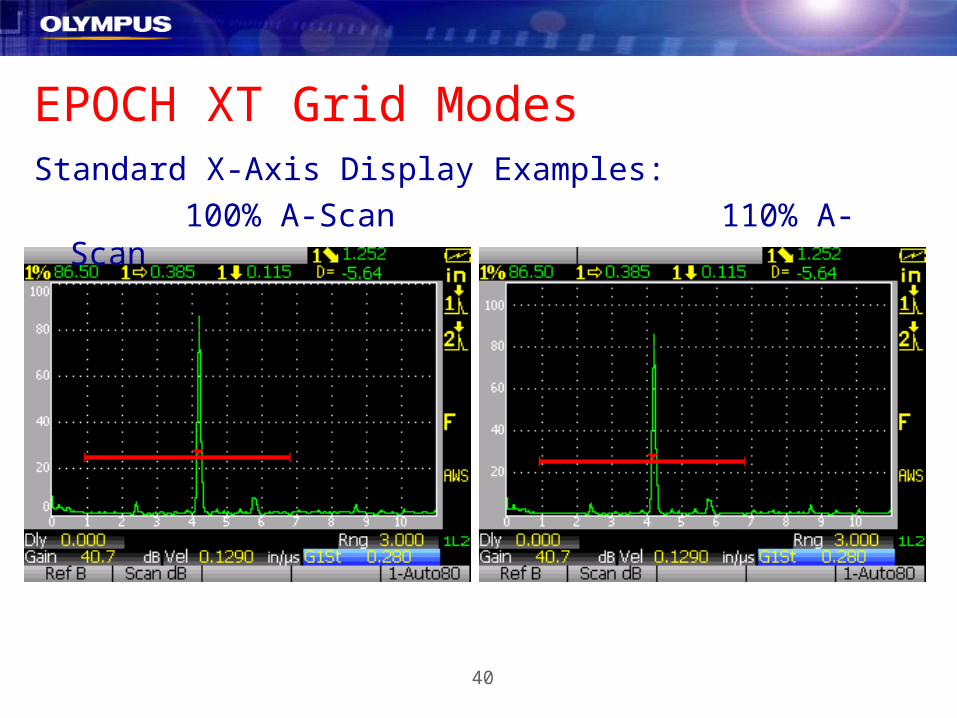
The Y-Axis has two display modes:– 100%: Displays amplitude from 0 to 100% screen height just like the EPOCH
4 Series. Amplitude is measured to 110%.– 110%: Displays amplitude from 0 to 110% screen height. Allows easy
instrument setup to 100% for linearity or other system checks.
40
EPOCH XT Grid ModesStandard X-Axis Display Examples:
100% A-Scan 110% A-Scan

41
EPOCH XT Grid ModesSoundpath X-Axis Display Examples:
100% A-Scan 110% A-Scan

42
EPOCH XT Grid ModesLeg X-Axis Display Examples:
100% A-Scan 110% A-Scan
43
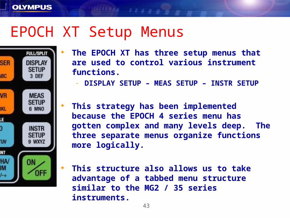
EPOCH XT Setup Menus The EPOCH XT has three setup menus that are used
to control various instrument functions.– DISPLAY SETUP – MEAS SETUP – INSTR SETUP
This strategy has been implemented because the EPOCH 4 series menu has gotten complex and many levels deep. The three separate menus organize functions more logically.
This structure also allows us to take advantage of a tabbed menu structure similar to the MG2 / 35 series instruments.
44
EPOCH XT Setup Menu Structure All of the menus in the EPOCH XT have been organized in a similar
manner and the navigation within the menus is standardized.
There are four types of controls that are found within a menu:– TABS– SUB-LEVEL TABS– CONTROL GROUPS– PARAMETERS
Navigation and adjustment is accomplished by using the arrow keys and the enter key. In some cases the operator may use the direct entry method to enter parameter values if desired.
NOTE: Full instructions for menu navigation can be found in the instrument operating manual.

45
EPOCH XT Setup Menu NavigationTABS run across the top of the display when the operator enters one
of the setup menus:
The operator uses the Left and Right Arrow keys to move from one tab to the next. The active tab is highlighted by the instrument. The operator presses the [ENTER] key to select and move into a TAB.

46
EPOCH XT Setup Menu NavigationSUB-LEVEL TABS run vertically on the left side of the display. These
are only present in some of the EPOCH XT TABS.
In the screenshot to the left the operator has already selected the TAB “EditPara” by highlighting it and pressing [ENTER].
The operator is now navigating through a set of vertical SUB-LEVEL TABS. He must use the Up and Down Arrow keys to select a tab (highlight it), and press [ENTER] to enter the SUB-LEVEL TAB.
Pressing [2nd F], [ENTER] will bring the operator back to the “EditPara” TAB.

47
EPOCH XT Setup Menu NavigationCONTROL GROUPS are sets of PARAMETERS that have been
grouped together based on their function. These are located within
TABS or SUB-LEVEL TABS depending on the setup menu. CONTROL
GROUPS are usually surrounded by a box for visual reference.
In the screenshot to the right you see the “Meas” TAB in the MEAS SETUP Menu.
This TAB contains two CONTROL GROUPS.
CONTROL GROUP 1
CONTROL GROUP 2

48
EPOCH XT Setup Menu NavigationIn this example the operator has used the Left and Right Arrow Keys to select the
“Meas” TAB. To enter the first CONTROL GROUP he must press [ENTER]. To
enter the second CONTROL GROUP he must press [ENTER] again. Since there is
no third CONTROL GROUP in this TAB, pressing the [ENTER] key again will bring
the operator back to the “Meas” TAB.
1st [ENTER] Press 2nd [ENTER] Press 3 rd [ENTER] Press

49
EPOCH XT Setup Menu NavigationPARAMETERS are selected (highlighted) using the Up and Down
Arrow keys. They are typically adjusted using the Left and Right
Arrow keys, but in some cases the operator may use direct entry.
In the screenshot to the right the operator has used the [ENTER] key to select CONTROL GROUP 2, and the Up and Down Arrow keys to select the “X Value” PARAMETER.
The Value of the “X Value” PARAMETER is adjusted using the Left and Right Arrow keys, or by pressing [ALPHA/NUM], entering the desired value, and then pressing [ENTER].
50
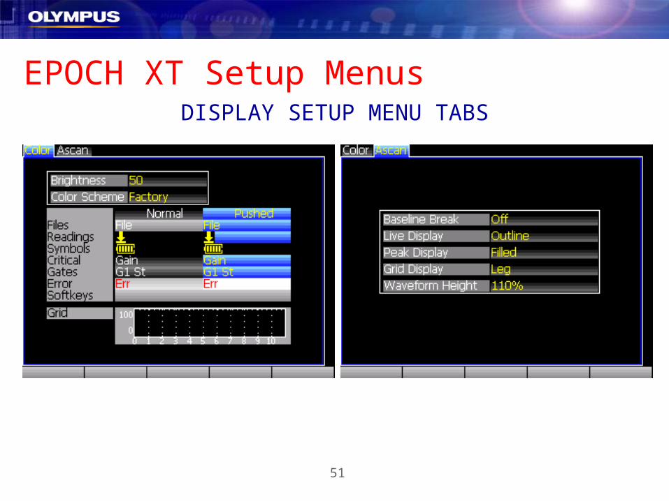
EPOCH XT Display Setup MenuThis menu is used to control how the instrument will display
information on the screen. There are two tabs within this menu:
Color TAB:– Controls for instrument color scheme– Brightness control– Shows examples of display appearance for a selected color scheme
A-Scan TAB:– BASELINE BREAK selection– Live A-Scan and Peak Mem/Hold A-Scan filled or hollow– Grid setup for X and Y axes.
51
EPOCH XT Setup MenusDISPLAY SETUP MENU TABS

52
EPOCH XT Measurement Setup MenuThis menu is used to select the 5 displayed measurements, control
gate measurement modes, and to setup options/features like
DAC/TVG, DGS, AWS, etc. There are three tabs:
Meas TAB:– Select displayed measurements– Select units (in, mm, usec)– Select measurement resolution for thickness and amplitude– Calibration mode Soundpath or Depth– X-Value same as EP4 series X-Correct– CSC setup (now a standard feature)– Select Trigger Mode

53
EPOCH XT Setup Menus Gates TAB:
– Activate Gate 2 Tracking. This forces Gate 2 to track the position of a measurement in Gate 1 similar to Echo-to-Echo in an EPOCH 4.
– GATE 1 Measurement Mode (PEAK, EDGE, FIRST PEAK)– GATE 2 Measurement Mode (PEAK, EDGE, FIRST PEAK)– GATE 1 Polarity (DEFAULT, POS, NEG)– GATE 2 Polarity (DEFAULT, POS, NEG)
Options TAB– DAC/TVG– DGS/AVG– AWS– More to come…

54
EPOCH XT Setup MenusMEAS SETUP MENU TABS

55
EPOCH XT Setup MenusMEAS SETUP MENU TABS

56
EPOCH XT Instrument Setup MenuINSTR SETUP – This menu is used to select preferences, regional
settings, control Editable Parameters, and check instrument status.
General TAB:– Pulser Mode (Square or Spike) – Filter Group (Standard or other custom groups)– Language– Key Beep– Alarm Beep– All Lock– Cal Lock– Locale for Radix and Date Pattern– Temperature Calibration mode (Auto or Manual)– Date and Time settings

57
EPOCH XT Instrument Setup MenuINSTR SETUP – This menu is used to select preferences, regional
settings, control Editable Parameters, and check instrument status.
EditPara TAB:– Editable Parameters similar to EP4 series
Status TAB:– Instrument information
Splash Screen TAB– Setup company info for startup screen

58
EPOCH XT Setup MenusINSTR SETUP MENU TABS

59
EPOCH XT Setup MenusINSTR SETUP MENU TABS

60
EPOCH XT
Software Options

61
EPOCH XT DAC/TVGThe EPOCH XT DAC/TVG feature is standard in all instruments. This
feature is similar to the Advanced DAC/TVG option in the EPOCH 4
series instruments with improvements.
DAC/TVG Operation Modes: ASME ASME III CUSTOM JIS 20-80% TVG Table
62
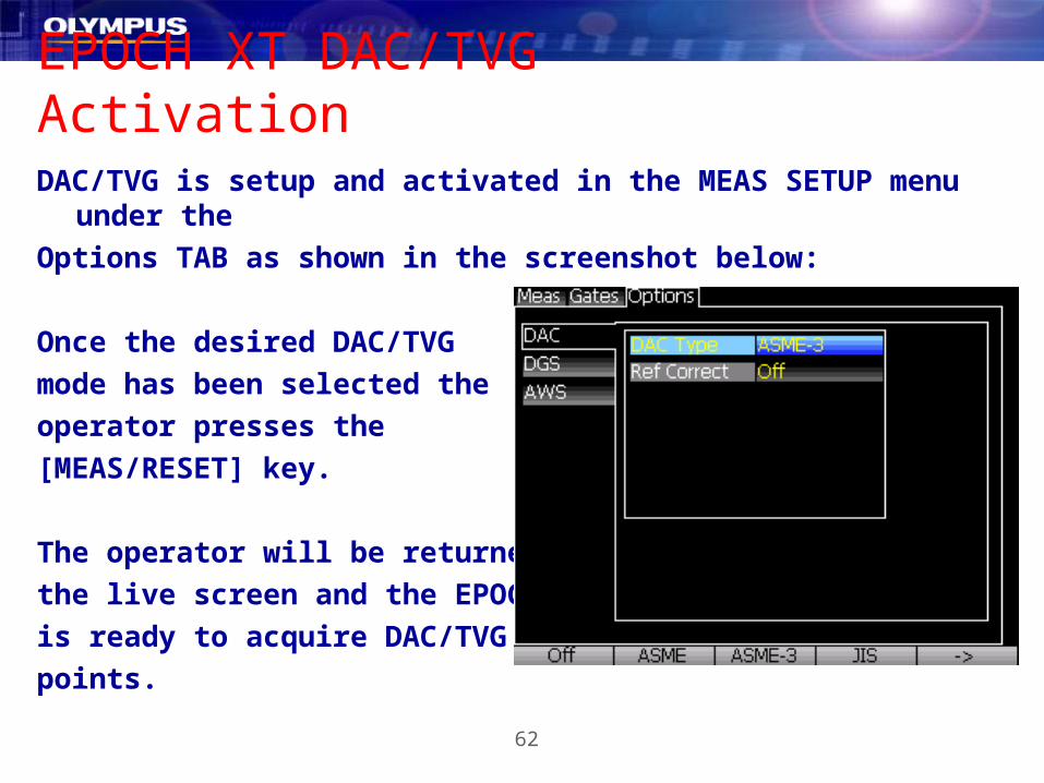
EPOCH XT DAC/TVG ActivationDAC/TVG is setup and activated in the MEAS SETUP menu under the
Options TAB as shown in the screenshot below:
Once the desired DAC/TVG
mode has been selected the
operator presses the
[MEAS/RESET] key.
The operator will be returned to
the live screen and the EPOCH
is ready to acquire DAC/TVG
points.

63
EPOCH XT DAC/TVG SetupThe DAC/TVG Setup Procedure is the same for ASME, ASME III,
Custom and JIS DAC modes.
DAC/TVG Setup Steps:
1. Position Gate 1 over the first echo.
2. Press [F5] (Auto 80%)
3. Press [F1] to capture the point
4. Position Gate 1 over the next echo
5. Repeat steps 2-4 until all points are captured.
6. Press [F4] (DONE) to complete the setup.
Other Functions:
♦ DELETE – Deletes the last captured point.
♦ ERASE – Erases the entire DAC/TVG setup.

64
EPOCH XT DAC/TVG OperationOnce the DAC/TVG points have been captured the operator is ready to
use the instrument’s DAC/TVG setup. The curves are fully dynamic
with Range, Delay, Gain, and Zoom. The F-Key Functions are:
F1 = DAC/TVG View – Switches between the DAC and TVG views of the setup.
F2 = DAC/TVG Gain – Allows the operator to move the DAC/TVG curves and the echoes vertically to achieve accurate and code-compliant defect sizing.
F3 = Gain Step – This parameter sets the adjustment step for DAC/TVG Gain.
F5 = Next DAC/TVG – Rotates through the available DAC/TVG curves. Measurements are taken based on the currently selected curve (double thickness on screen).

65
Special DAC/TVG Modes - CustomThe Custom DAC/TVG feature allows the operator to setup up to three
warning curves (plus the main curve) from +10dB to -24dB from the
main curve. The operator must choose the number of curves in the
activation procedure. After that, the setup is the same as ASME DAC.

66
Special DAC/TVG Modes – 20-80%20-80% DAC uses a combination of DAC and TVG to keep the DAC
curve between 20% and 80% screen height. The only difference in the
setup procedure is that the operator does not use the Auto-80%
feature before each point is captured.

67
Special DAC/TVG Modes – TVG TableThe TVG Table in the EPOCH XT is an advanced feature that is used
to
create fully customized TVG setups. These setups are not linked to
any DAC setup. Typical uses include:
Building custom TVG’s for immersion inspection Building TVG’s for large forging inspections using DGS/AVG diagrams
for the transducer that will be used Suppress Interface and Backwall echoes to achieve better near and far
surface resolution. Eliminating near surface noise in materials like composites while using
high gain in the far field to see clearly see the backwall and far surface defects.

68
Special DAC/TVG Modes – TVG TableIn the example below the TVG Table is being used for three purposes: Equalize defect echo heights throughout the test piece Suppress the interface echo when the sound enters the test piece. This
allows near surface defects to be detected. Suppress the backwall echo so it can be monitored on-screen and to
allow detection of far surface defects.

69
Special DAC/TVG Modes – TVG Table
Near Surface Defect Far Surface Defect
TVG Table Specifications are by far best in class: Dynamic Gain Adjustment – 110dB (competitors offer 40dB) Slope – Up to 100dB/usec* (competitors offer 12dB/usec to 40dB/usec) Number of Points – 50 (competitors offer 10 to 20 points)
*Depends on Filter Setting

70
EPOCH XT DGS/AVGThe EPOCH XT offers DGS/AVG as an added-cost option. The
functionality of the option is very similar to the onboard DGS/AVG
option in the EPOCH 4 series. All recent updates in the EPOCH 4
series have been carried over into the EPOCH XT.
Registration Level is adjustable on the
live screen. Delta Vt (Transfer Correction) is
adjustable on the live screen. X-Value is adjustable in DGS/AVG setup.

71
DGS/AVG ActivationThe DGS/AVG option is activated in the MEAS SETUP menu under the
Options TAB. The Activation steps are listed below:1. Turn DGS/AVG ON
2. Select Probe Typea. Library Straight Beam
b. Library Angle Beam
c. Library Dual
d. Custom Straight Beam
e. Custom Angle Beam
3. Select Probe
4. Select Reference Reflector
5. Enter Transfer Correction
6. Enter Registration Level
7. Enter Warning Level
8. Enter Attenuation Corrections
9. Enter X-Value for AB Probes
72
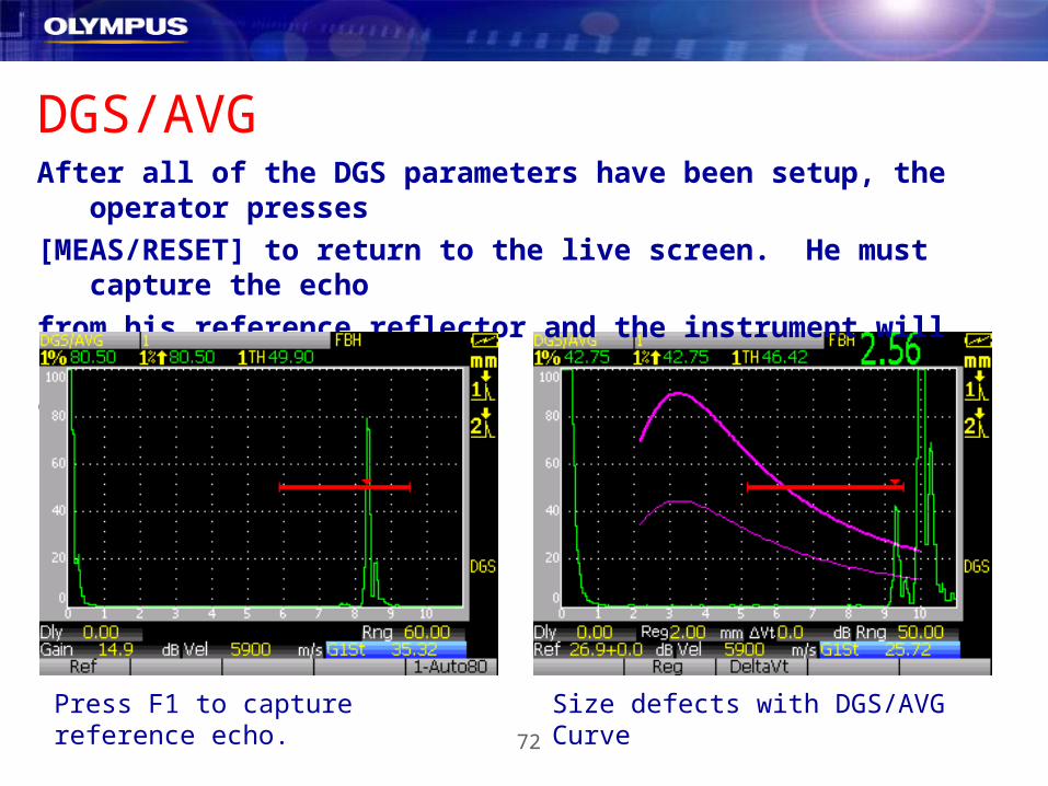
DGS/AVGAfter all of the DGS parameters have been setup, the operator presses
[MEAS/RESET] to return to the live screen. He must capture the echo
from his reference reflector and the instrument will draw the DGS/AVG
curves on the display.
Press F1 to capture reference echo. Size defects with DGS/AVG Curve

73
EPOCH XT AWS D1.1 / D1.5 The EPOCH XT AWS D1.1 / D1.5 Software Option is
intended to assist operators performing weld inspections according to AWS D1.1 / D1.5 regulations.
74
EPOCH XT AWS D1.1 / D1.5◆ While performing the inspection, the EPOCH provides the operator
with the calculated D value (A-B-C=D) used to evaluate welds.
━ A (Indication Level): Automatically calculated in the EPOCH 4 for any indication echo less than 100% Full Screen Height.
━ B (Reference Level): User entered at instrument calibration. ━ C (Attenuation Factor): Automatically calculated based on the EPOCH
Soundpath Calculator.
◆ The EPOCH saves all data for A, B, C, and D for later review and
inspection report generation.

75
AWS Activation◆ The AWS D1.1 / D1.5 Option is activated in the MEAS SETUP Menu
under the Options TAB.

76
AWS Activation◆ After AWS D1.1 / D1.5 is turned ON, the operator must capture a
reference echo. This is shown in the screenshots below:

77
AWS Measurement◆ Once the reference echo has been captured the EPOCH XT will
automatically provide a D rating for a non-saturated gated reflector. This is shown below:
◆ The instrument will store all setup parameters, measurements, the A-Scan, as well as the values for A, B, C, and D from the AWS formula.
78
EPOCH XT
Calibration
79
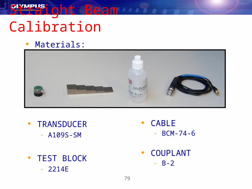
Straight Beam Calibration Materials:
CABLE– BCM-74-6
COUPLANT– B-2
TRANSDUCER– A109S-SM
TEST BLOCK– 2214E

80
Straight Beam Calibration Parameters Reset
– Parameters Reset will revert to the factory default settings.
PRESS:
In the RESETS section,Select PARAMETERS:
Press to Exit this SETUP when completed
To Reset
To Confirm

81
Straight Beam Calibration Place a Drop of Couplant on the .200” and .500” Steps and
set the transducer on the .200” (THIN STANDARD) step.
INSTRUMENT PARAMETERS SETUP
10 dB of Gain =
.2320 in/uS Velocity =

82
Straight Beam CalibrationINSTRUMENT PARAMETERS SETUP
5 Mhz Transducer =
1.5 – 8.5 Filter =
1” Range =

83
Straight Beam CalibrationCAPTURE AND CALIBRATE
Gate 1 Start = .200”
Gate 1 Width = .200”
Echo Height = 80%
84
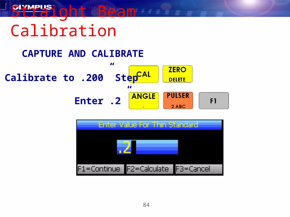
Straight Beam CalibrationCAPTURE AND CALIBRATE
Calibrate to .200” Step
Enter .2”

85
Straight Beam Calibration
Move the transducer to the .500” step (THICK STANDARD)CAPTURE AND CALIBRATE
Gate 1 Start = .500”
Echo Height = 80%

86
Straight Beam CalibrationCAPTURE AND CALIBRATE
Calibrate to .500” Step
Enter .5”
87
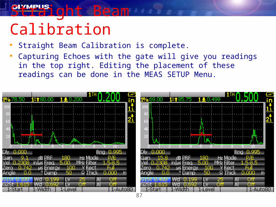
Straight Beam Calibration Straight Beam Calibration is complete. Capturing Echoes with the gate will give you readings in the top right.
Editing the placement of these readings can be done in the MEAS SETUP Menu.
88
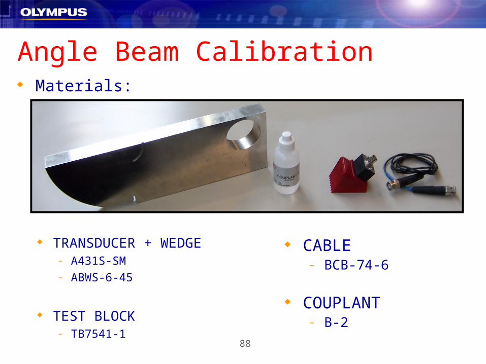
Angle Beam Calibration Materials:
CABLE– BCB-74-6
COUPLANT– B-2
TRANSDUCER + WEDGE– A431S-SM– ABWS-6-45
TEST BLOCK– TB7541-1

89
Angle Beam Calibration
4 Steps for an Angle Beam Calibration
– 1. Locate the Beam Index Point (BIP) of the Probe.
– 2. Verify the Refracted Angle
– 3. Calibrate for Distance (Using the Auto-Cal Feature)
– 4. Calibrate for Sensitivity
90
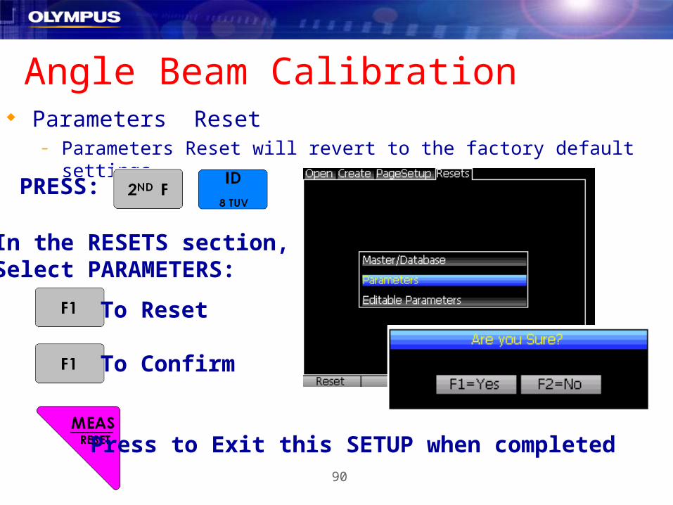
Angle Beam Calibration Parameters Reset
– Parameters Reset will revert to the factory default settings.
PRESS:
In the RESETS section,Select PARAMETERS:
Press to Exit this SETUP when completed
To Reset
To Confirm

91
Angle Beam Calibration INITIAL SETUP
50 dB of Gain =
.1280 in/us Velocity =
45 Deg Angle =
2.25Mhz Transducer =
10” Range =
.5 – 4.0 Mhz Filter =
2.27 Mhz

92
Angle Beam Calibration Locate the Beam Index Point:
– 1. Align the wedge with the zero mark on the “IIW Type I Block”
– 2. Move the transducer forward and backward until the echo amplitude from the 4” arc is peaked (The Peak Memory can be used for this by pressing: )
– 3. After the signal has been peaked, mark on the wedge directly over the zero mark on the IIW. This is the Beam Index Point.
1/4 Locate Beam Index Point

93
Angle Beam Calibration Verify the Refracted Angle
– 1. Position the transducer over the appropriate angle mark on the IIW Block (In this case it is the 45 deg located on the bottom side of the IIW).
– 2. Mover the transducer forward and backward to “peak up” echo from the large circular hole in the block. Peak Memory aids in this process by pressing .
2/4 Verify Refracted Angle
94
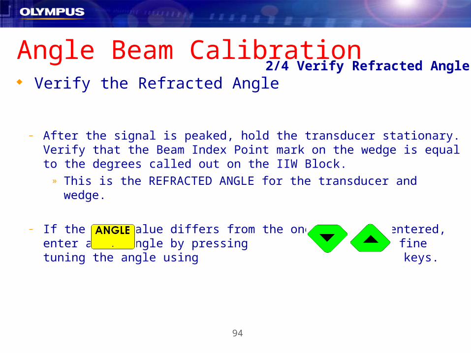
Verify the Refracted Angle
Angle Beam Calibration
– After the signal is peaked, hold the transducer stationary. Verify that the Beam Index Point mark on the wedge is equal to the degrees called out on the IIW Block.
» This is the REFRACTED ANGLE for the transducer and wedge.
– If the Beta Value differs from the one initially entered, enter a new angle by pressing and fine tuning the angle using keys.
2/4 Verify Refracted Angle
95
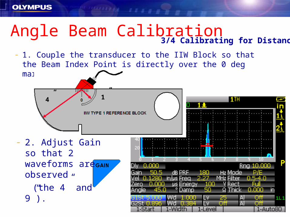
– 1. Couple the transducer to the IIW Block so that the Beam Index Point is directly over the 0 deg mark.
Angle Beam Calibration
4” 1”
– 2. Adjust Gain so that 2 waveforms are observed
(the 4” and 9”).
3/4 Calibrating for Distance

96
Angle Beam Calibration Peak the 4” echo using
Press to capture the echo and press Auto-8
With the Gate on the 4” echo, press then
Enter
Then to continue
Note: The Peak Mem must be turned off before pressing the CAL key
3/4 Calibrating for Distance

97
Angle Beam Calibration Move the Gate to the 9”
echo and bring it to 80%– Auto-80 Feature
Press then
Enter the distance of 9” by
followed by
3/4 Calibrating for Distance

98
On the underside of the IIW Block, peak the 0.060” hole
GATE button, bring the peak of this echo to 80%
Press then This sets the Ref Gain
Angle Beam Calibration
0.060” sidedrilled hole
4/4 Calibrating for Sensitivity

99
The Reference Gain has been set.
To adjust Scanning dB:– In 6.0 dB Increments
Angle Beam Calibration4/4 Calibrating for Sensitivity
– In 0.1 dB Increments

100
EPOCH XT
Datalogger
101
EPOCH XT DataloggerThe EPOCH XT has an advanced datalogger designed for typical flaw
detection use and also for corrosion thickness gauging surveys.
The datalogger is located in a menu similar to the three setup menus discussed previously.
The datalogger allows the operator to setup several file types– Incremental– Sequential – Seq. with Custom Pt.– 2D
Up to 10,000 IDs may be saved. Every ID contains: Operator selected measurements, A-Scan, Instrument Setup, Software Option Setup, Alarm Conditions, Display Flags/Markers, and Peak Mem / Peak Hold conditions.
– 2D with Custom Pt. – 2D EPRI– 3D– Boiler

102
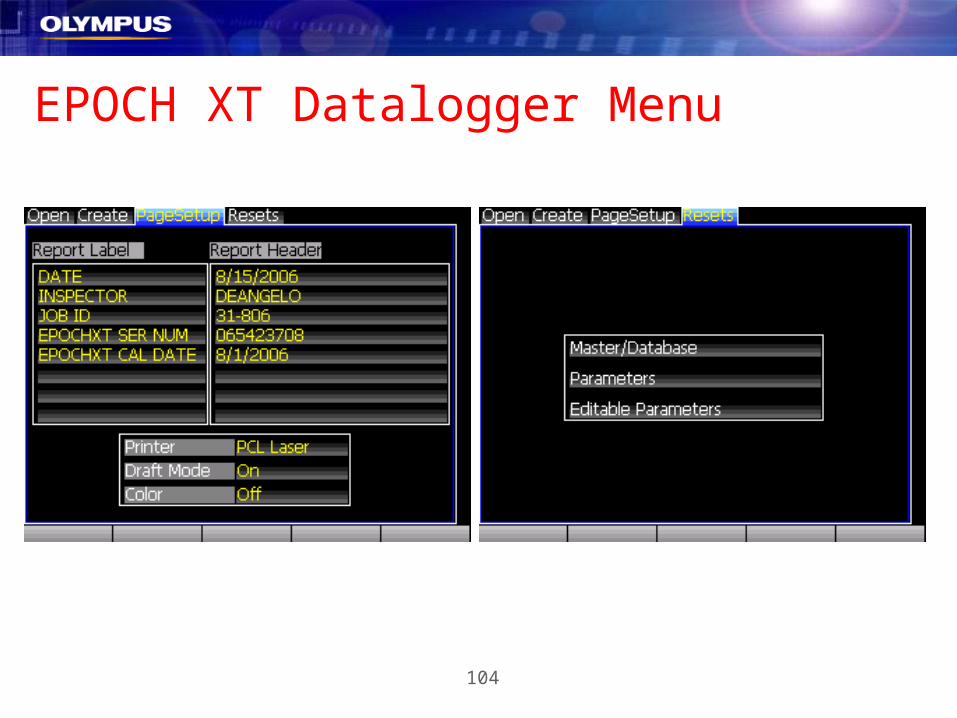
EPOCH XT Datalogger The operator has the ability to enter additional information for each file
created:– Description– Inspector ID– Location Note
Onboard Reports with customized
headers may be created.
Instrument Parameter and Database
resets may be performed

103
EPOCH XT Datalogger Menu
PRESS:
104
EPOCH XT Datalogger Menu

105
EPOCH XT File Open TAB The File “Open” TAB displays a list of all of the files in the EPOCH
XT’s datalogger. The operator uses the Up and Down Arrow Keys to highlight the
desired file. For the highlighted file the instrument will display:
– Filename– File Type– Date and Time Created– Description– Inspector ID– Location Note
There are two levels of Function
key presets in this TAB.– Level 1– Level 2
106
EPOCH XT File Open TABFile Open Tab Function Key Descriptions
OPEN – This will open the selected file and return the operator to the live screen. This does NOT recall any instrument setup parameters. This function only makes the opened file the current “save-to” location.
CONTENTS – This function allows the operator to view the individual stored IDs within a file. You will see all stored measurements, the A-Scan, Setup Parameters, etc.
SUMMARY – This function allows the operator to view the saved measurements for each stored ID within the file.
CANCEL – Returns the operator to the live A-Scan display.
107
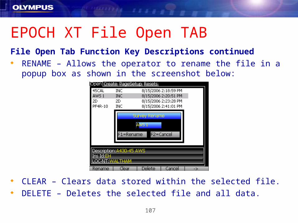
EPOCH XT File Open TABFile Open Tab Function Key Descriptions continued RENAME – Allows the operator to rename the file in a popup box as
shown in the screenshot below:
CLEAR – Clears data stored within the selected file. DELETE – Deletes the selected file and all data.

108
EPOCH XT File CONTENTSWhen the operator view the contents of a file he will see a scrollable
window as shown in the screenshots below:
The operator uses the up and down arrow keys to view the entire ID.
The top of the window shows the A-Scan and instrument measurements.
The bottom of the window shows the instrument setup parameters and any additional measurements. In this case you see AWS D1.1 related measurements displayed at the bottom of the ID window.
The operator uses the Left and Right Arrow keys to move from one ID to the next within the file.

109
EPOCH XT File CONTENTSWhen the operator view the contents of a file he will see a scrollable
window as shown in the screenshots below:
File CONTENTS Function Key Descriptions:
♦ FIRST – Jumps to the first ID in the file.
♦ LAST – Jumps to the last ID in the file.
♦ RECALL – Recalls the selected ID and returns to the live screen. The instrument setup will be frozen on recall. The operator must press [MEAS/RESET] to begin inspecting.
♦ CLEAR – Clears the data in the selected ID
♦ FIND – Allows the operator to type in the name of an ID and jump directly to it.

110
EPOCH XT File SUMMARYWhen the operator view the contents of a file he will see a scrollable
window as shown in the screenshot below:
This window shows a list of all of the ID’s within the file, the measurement units (in, mm, or usec), and the measurements that the operator has chosen to store.
Up to 5 measurements can be stored and viewed for each ID#.
ID# File Name Measurements Unit
111
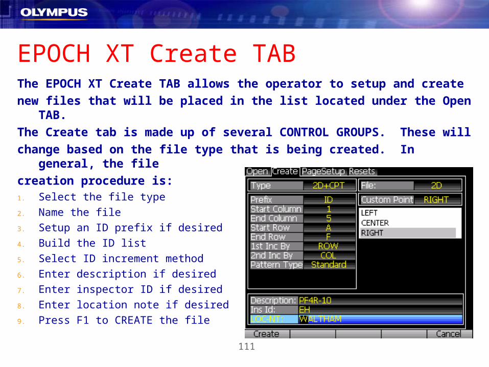
EPOCH XT Create TABThe EPOCH XT Create TAB allows the operator to setup and create
new files that will be placed in the list located under the Open TAB.
The Create tab is made up of several CONTROL GROUPS. These will
change based on the file type that is being created. In general, the file
creation procedure is:1. Select the file type
2. Name the file
3. Setup an ID prefix if desired
4. Build the ID list
5. Select ID increment method
6. Enter description if desired
7. Enter inspector ID if desired
8. Enter location note if desired
9. Press F1 to CREATE the file
112
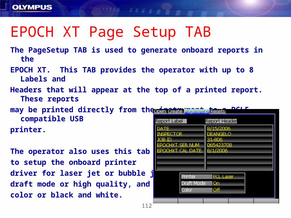
EPOCH XT Page Setup TABThe PageSetup TAB is used to generate onboard reports in the
EPOCH XT. This TAB provides the operator with up to 8 Labels and
Headers that will appear at the top of a printed report. These reports
may be printed directly from the instrument to a PCL5 compatible USB
printer.
The operator also uses this tab
to setup the onboard printer
driver for laser jet or bubble jet,
draft mode or high quality, and
color or black and white.
113
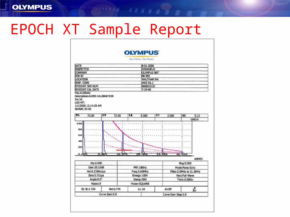
EPOCH XT Sample Report

114
EPOCH XT Resets TabThe Resets TAB is used to reset the instrument to the condition it was
in when it shipped from the factory. Master / Database – Resets all parameters and clears the instrument’s
datalogger. This will also shut down the instrument.
Parameters – Loads the factory default setup parameters and returns the operator to the live A-Scan display.
Editable Parameters – Reloads factory
values for all function key presets.

115
EPOCH XT
Accessories

116
EPOCH XT Accessories Batteries – When placing an order you will be able to specify NiMH or
Lithium Ion battery. The instrument
and its external charger can charge
both battery types.
C-Cells – All EPOCH XTs have the ability to use Alkaline C-Cell batteries. Every instrument will ship with a foam block to help hold C-Cell batteries in place before the battery door is closed.

117
EPOCH XT Accessories
External Charger – The EPOCH XT has an external “smart” battery charger available as an option. This battery charger has the ability to “calibrate” these batteries periodically greatly extending their useful life.
Sun Shade – The sun shade casts a shadow on the EPXT display. Outdoor conditions might require this accessory for better visibility. The sun shade grips onto the XXX with or without the Rubber Boot.
118
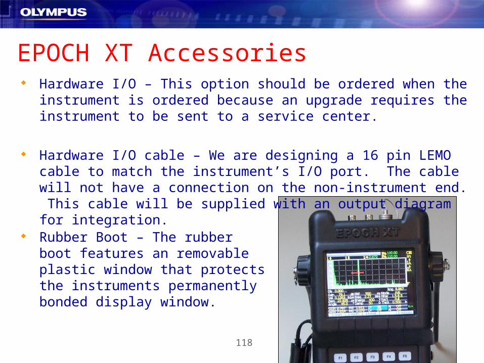
EPOCH XT Accessories Hardware I/O – This option should be ordered when the instrument is
ordered because an upgrade requires the instrument to be sent to a service center.
Hardware I/O cable – We are designing a 16 pin LEMO cable to match the instrument’s I/O port. The cable will not have a connection on the non-instrument end. This cable will be supplied with an output diagram for integration.
Rubber Boot – The rubber boot features an removable plastic window that protects the instruments permanently bonded display window.

119
EPOCH XT Accessories Chest Harness – The EPOCH 4 chest harness is available for use with
the EPOCH XT. Since D-Rings are case mounted the Rubber Boot is not required for chest harness use.
Transport Case – The EPOCH XT Transport case is being designed to allow more storage of transducers, extra batteries, cables, couplant, etc.

120
Questions??