emergency information: leave tem as is. do not shut down ... · philips cm200 200kv tem simplified...
TRANSCRIPT

2017.07.07
1
Emergency Information:
1. Medical Emergencies: Contact 911 and McGill Security 514.398.3000
2. Leave TEM as is. Do NOT shut down the vacuum system.
3. If possible, turn off High Tension and Close Column Valve.
4. Exit the Room/Building.
Emergency Contact Information:
• David Mui – Staff Scientist: Cell 438.938.6886; Email: [email protected]
• S. Kelly Sears – Facility Manager: Cell 514.576.1926; Email: [email protected]
• Joaquin Ortega – Director: Office 514.398.6348; [email protected]
Philips CM200 200kV TEM Simplified Operating Manual
(Prepared by David Liu, S Kelly Sears and Joaquin Ortega) Safety
• Do not wander behind the microscope or step on cables.
• There is one computer for the CM200 TEM.
1. The support PC (SPC) is for taking digital images with the AMT XR41B CCD camera and
collecting spectra with the EDAX Genesis Energy Dispersive Spectrometer (EDS) and
Genesis software. Note: Ensure you copy your data at the end of each TEM session.
Data older than three months may be deleted without notice.
Protective Equipment
• Nitrile gloves for handling sample holder and safety glasses for filling liquid nitrogen
dewar.
1. Initial Set-up
• When the CM200 is operational, the White Standby and
Red Microscope Off buttons will be illuminated and the
White On button will be dark on the front console. Lit
buttons indicate their availability as emergency
functions while the microscope is running.

2017.07.07
2
• ROTATE the Panel Dim knob to illuminate
the console panel lighting and emission
gauge. Clockwise rotation of the Data Dim
knob increases the brightness of the CRT
screen.
• VERIFY the UHV and HIVAC indicator lights
on the console are lit (Green). If they are
NOT lit, PRESS the Vacuum System On
button and wait (20 to 30 minutes) until
the two lights come on.
• VERIFY the black rubber mat is covering the viewing
window and carefully FILL the anti-contaminator cold
finger dewar (cold trap) with liquid nitrogen. The first
dewar flask of the day should last ~30 to 40 minutes.
Later dewars will each last 2 to 3 hours. Do NOT allow the
cold finger to fall below 50% or to warm up as the column
vacuum will deteriorate significantly. REPLACE the
styrofoam cap on the top of the dewar.
• The CRT screen will display the CM200 status startup
page or, more likely, one of the Modes or Mode
Selection pages. If the Ready light (on the pushbutton
directly below the CRT screen, to the right) is lit,
pressing it will move the screen selection back in the
hierarchy of the pages. PRESS the Modes key to obtain
the Mode Selection page.
2017.07.07
3
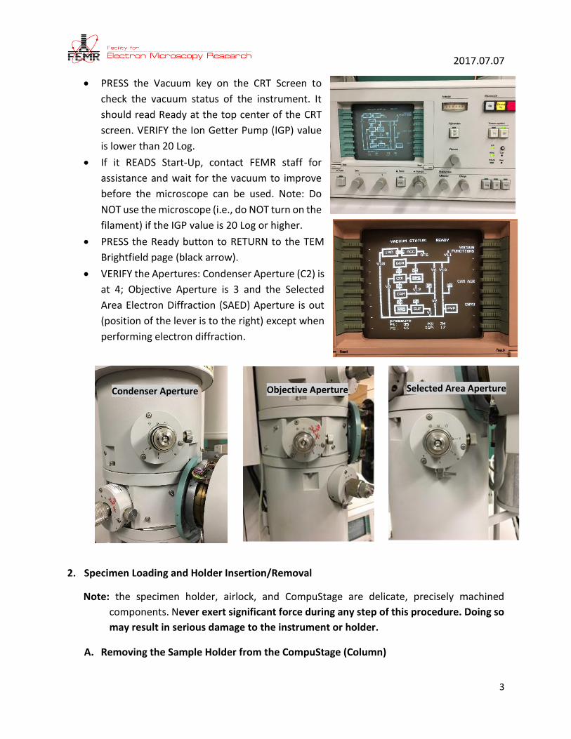
• PRESS the Vacuum key on the CRT Screen to
check the vacuum status of the instrument. It
should read Ready at the top center of the CRT
screen. VERIFY the Ion Getter Pump (IGP) value
is lower than 20 Log.
• If it READS Start-Up, contact FEMR staff for
assistance and wait for the vacuum to improve
before the microscope can be used. Note: Do
NOT use the microscope (i.e., do NOT turn on the
filament) if the IGP value is 20 Log or higher.
• PRESS the Ready button to RETURN to the TEM
Brightfield page (black arrow).
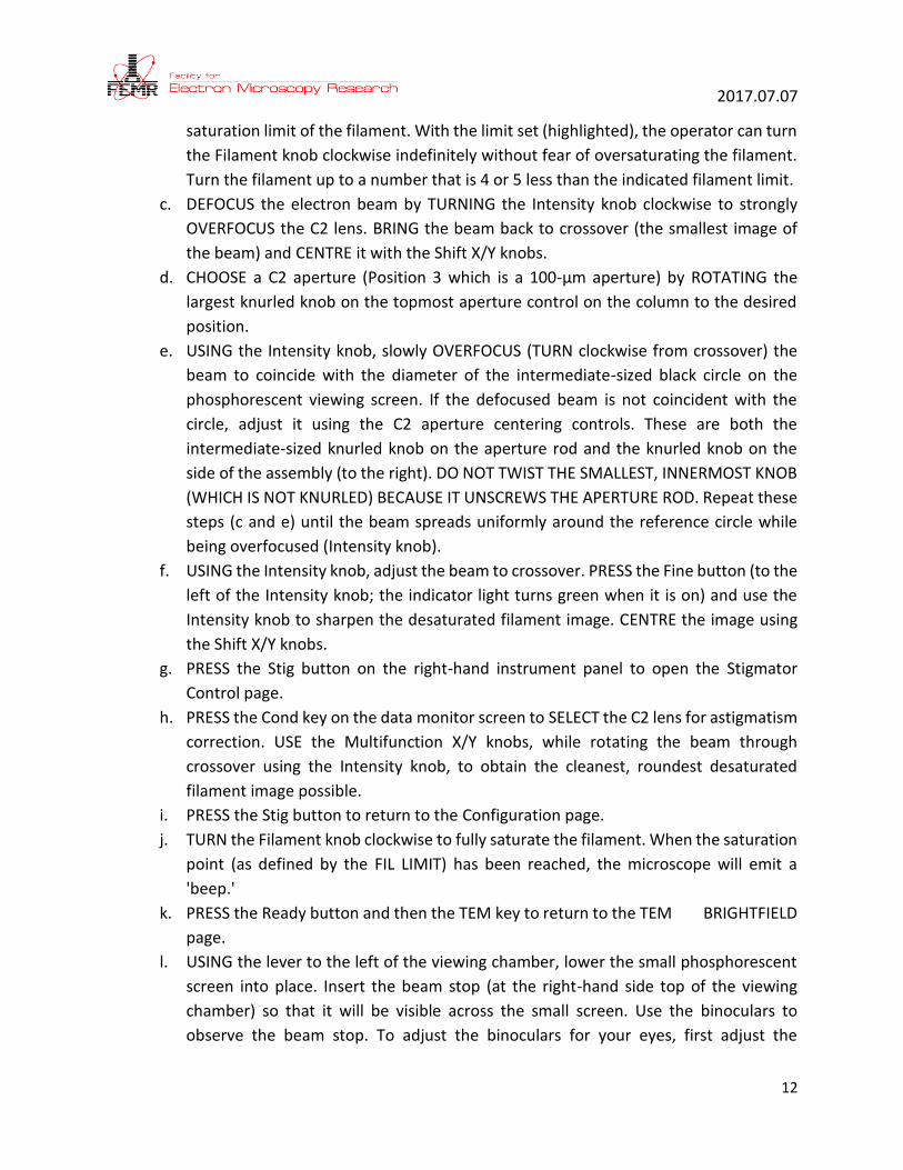
• VERIFY the Apertures: Condenser Aperture (C2) is
at 4; Objective Aperture is 3 and the Selected
Area Electron Diffraction (SAED) Aperture is out
(position of the lever is to the right) except when
performing electron diffraction.
2. Specimen Loading and Holder Insertion/Removal
Note: the specimen holder, airlock, and CompuStage are delicate, precisely machined
components. Never exert significant force during any step of this procedure. Doing so
may result in serious damage to the instrument or holder.
A. Removing the Sample Holder from the CompuStage (Column)
Condenser Aperture Objective Aperture Selected Area Aperture

2017.07.07
4
a. RESET the sample stage.
b. Always keep light pressure on the purple goniometer surface when removing the
sample holder. PULL the holder straight back without rotating until it stops moving.
c. ROTATE the holder clockwise until it stops. This rotation moves the guide pin
approximately from the 12 o’clock to 5 o’clock position.
d. Gently, while keeping pressure on the goniometer, PULL the sample holder back to
break the airlock vacuum. This will require a small amount of force.
e. REMOVE the holder straight back out of the goniometer while being careful not to
scrape it along the inside of the airlock. Do NOT to touch the holder O-ring or any part
to the tip with bare hands.
B. Specimen Loading
Note: NEVER mount magnetic samples or discs in the clamp holder of the Single Tilt
Sample Holder. The clamp spring is not strong enough to prevent the specimen from
attaching to the objective lens polepiece. Use the Double Tilt Sample Holder for
magnetic samples. NEVER touch the O-ring to the tip of the holder without wearing
nitrile gloves.
a. PLACE the sample holder in the protective stand.
b. REMOVE the sample loading tool from the base of the stand.
c. Using one hand to prevent the holder from slipping out of the stand, INSERT the tool
into the hole in the specimen clamp and GENTLY RAISE the clamp straight up until it
stops.

2017.07.07
5
d. TRANSFER the TEM grid into the recess
at the end of the holder using the
tweezers.
e. Use the pin tool to gently LOWER the
clamp straight down to hold the grid
securely. RETURN the tool to the base of
the holder stand. To make scanning the
grid easier, you may wish to orient one
set of grid bars parallel to the long axis of
the specimen holder.
f. RETRACT the holder slightly and turn it
upside down. TAP the back end several
times, then turn the holder upright and check that the grid has not moved (movement
suggests the grid is not properly secured).
g. Use the microscope to inspect the holder O-ring for debris. Gently remove any debris
using a sheet of Kimwipe.
C. Inserting the Sample Holder into the CompuStage
a. Carefully ORIENT the Airlock (Sample Holder) Pin on the sample holder with the 5
o’clock position on the CompuStage and gently INSERT the holder into the Airlock
Entryway until it stops. Be careful NOT to scrape the tip on the inner mechanism of
the goniometer. You should feel some resistance as the sample holder O-ring seats
in the Airlock Chamber.
b. Before inserting the holder into the column, the holder needs to be pre-pumped until
the indicator is off.
c. The data monitor screen will automatically open to the Holder Selection Page. PRESS
the appropriate key and then PRESS the Ready button (below the data monitor
screen).
d. The Airlock will begin pumping and the Red LED on the CompuStage will illuminate.
Do NOT move the Sample Holder when the Red LED is illuminated.

2017.07.07
6
e. After the pumping countdown reaches zero
and the Red LED goes out, SUPPORT the
purple goniometer surface with one hand
and GRIP the holder securely with the
other. Slowly ROTATE the holder
counterclockwise from 5 o’clock to 12
o’clock position.
f. Gently SLIDE the holder to into column of
the microscope until it stops. TAP the end
of the holder to make sure it is securely
seated.
g. After INSERTING the Sample Holder, WAIT
until the IGP value is lower than 20 Log.
h. VERIFY the apertures inserted are correctly
inserted. Condenser (Upper) and Objective
(Middle) apertures are inserted (lever to the left) and the dial at number 3. The
Selected Area Electron Diffraction (SAED) aperture (lower) should be retracted (lever
to the right).
3. High Tension (Accelerating Voltage) and Filament Saturation
a. To select the accelerating
voltage (High Tension), PRESS
the Parameters key to open the
Parameters pages. On the first
of these pages, the kV may be
modified by pressing the left
(lower the HT) or right (increase
the HT) key adjacent to the
High Tension kV notation on
the screen. VERIFY the High
Tension is 200 kV.

2017.07.07
7
b. Also on the first Parameters
page is the Emission setting.
Increase the filament current
to the saturation value by
TURNING the Filament knob on
the control panel which should
ordinarily be left at 1. A higher
value will produce a brighter
beam image but will also
shorten the lanthanum
hexaboride (LaB6) filament life.
4. TEM Observation
a. VERIFY the Vacuum
(both UHV and HIVAC
lights are illuminated
and the IGP is <20 Log).
b. Log in to the PC with the
Username and
Password: femr.

2017.07.07
8
c. On the PC screen, OPEN the CCD camera program by CLICKING the AMTV600 icon.
d. On the CRT, PRESS Ready, Mode, choose configuration page. Turn the filament
knob slowly until the Ext voltage reads 3.8. As a rule of thumb, rotate the knob
until you hear two clicks; wait; rotate again for two clicks; wait; repeat until
reaching 3.8.
e. OPEN the valve (from Close to Open, counterclockwise) to the right of the microscope. You should see the electron beam on the fluorescent screen. Move the region of interest of your sample to the middle of the viewing area with the Joystick.
f. On the TEM control panel, PRESS the
Auto Focus button.
g. On the AMTV600 window, CHANGE the
setting from Speedlive (button in red)
to Qualitylive by pressing the button
once.

2017.07.07
9
5. Focusing the Image and Diffraction Pattern
a. Focusing the image with the image wobbler
i. Set the Focus Step size (inner Step Size knob) to 5 and PRESS the D button to place
the microscope in Diffraction mode.
ii. ADJUST the Camera Length to 620 mm (NOT 6.2 m) using the Mag knob.
iii. ADJUST the Beam Intensity.
iv. Center the Objective Aperture and ACTIVATE the Focus Wobbler.
v. USING the Multifunction X/Y, ENUSRE the two spots are centered in the Objective
Aperture area.
vi. SELECT D, FOCUS (minimum blur), DEACTIVATE the Wobbler
6. Camera Control and Imaging
a. CREATING a new Background Image. Note: The background image compensates for
phosphor inhomogeneity and optical imperfection.
i. VIEW the electron beam on the TEM viewing screen.
ii. CENTRE the beam.
iii. REMOVE specimen from column or locate a hole on TEM grid
iv. SET the magnification to roughly the magnification you will take the images.
v. SPREAD the beam with C2 control clockwise so that the current is about 1.0
second on the exposure meter.
vi. LIFT the viewing screen and cover the viewing glass window with the black rubber
mat.
vii. On the AMT software, SELECT the menu item Corrections --> Acquire Background.
viii. ADJUST the intensity knob (C2) so the histogram on the AMT software is
approximately centred in the box. When this is correct, PRESS the orange
command button.
ix. It will take ~60 seconds for the background correction to be completed. WAIT until
the Click Live Imaging button is re-enabled.
b. On the AMTv600 program, PRESS Live Image.

2017.07.07
10
c. LOCATE a region of
interest on the sample
using the stage
joystick.
d. To accurately focus,
PRESS Focus. The
image will magnify
four times and enable
the imaging of the
carbon grain and fine
tune your focus.
e. Go to higher
magnification. Find
the correct defocus
and image your
sample
f. To save your image, SELECT File tab and Save As. In the Caption Line 1, enter the
filename.
g. PRESS Save with Caption.
7. Eucentric Height Adjustment
a. Using the Magnification knob, SET the
Magnification to 5,800x and the use the
Joystick to locate and centre a small
feature on the TEM grid, i.e. small hole or
particle
b. FOCUS the feature using the Step Size
knobs. The Outer Knob changes the Focus,
and the Inner Knob (i.e. the step size
adjustment) modifies the amount of focus
change per click of the Outer Knob.
c. FOCUS the feature using the knobs marked
Step Size. The Outer Knob changes the
Focus, and the Inner Knob (i.e. the step size
adjustment) modifies the degree of focus
change per click of the Outer Knob.

2017.07.07
11
d. From the TEM Brightfield page, PRESS
CompuStage; the CompuStage Register
Control page will appear.
e. PRESS the Alpha Wobbler key and the stage
will automatically rock through a tilt range
of +/- 15°.
f. USE the Z control lever on the Joystick to move
the specimen up or down to MINIMIZE the
apparent movement.
g. When completed, PRESS the Alpha Wobbler key
to deactivate the stage rocking and then PRESS
the Ready button to return to TEM Brightfield.
8. Beam Alignment
a. USING the Magnification knob, select a magnification of 17,500x.
b. PRESS the Modes key on the CRT screen to access the Mode Selection page, and then
PRESS Configuration. The Configuration page displays the Filament Heating status and
provides a schematic of the available apertures (Aperture Memo) for the condenser
2 (C2), objective, and selected area lenses. Under Cathode, at the top of the page,
LaB6 should be highlighted, indicating that a LaB6 filament is in use. Fil Limit should
be highlighted next to the number (usually between 22 and 30) indicating the
2017.07.07
12
saturation limit of the filament. With the limit set (highlighted), the operator can turn
the Filament knob clockwise indefinitely without fear of oversaturating the filament.
Turn the filament up to a number that is 4 or 5 less than the indicated filament limit.
c. DEFOCUS the electron beam by TURNING the Intensity knob clockwise to strongly
OVERFOCUS the C2 lens. BRING the beam back to crossover (the smallest image of
the beam) and CENTRE it with the Shift X/Y knobs.
d. CHOOSE a C2 aperture (Position 3 which is a 100-µm aperture) by ROTATING the
largest knurled knob on the topmost aperture control on the column to the desired
position.
e. USING the Intensity knob, slowly OVERFOCUS (TURN clockwise from crossover) the
beam to coincide with the diameter of the intermediate-sized black circle on the
phosphorescent viewing screen. If the defocused beam is not coincident with the
circle, adjust it using the C2 aperture centering controls. These are both the
intermediate-sized knurled knob on the aperture rod and the knurled knob on the
side of the assembly (to the right). DO NOT TWIST THE SMALLEST, INNERMOST KNOB
(WHICH IS NOT KNURLED) BECAUSE IT UNSCREWS THE APERTURE ROD. Repeat these
steps (c and e) until the beam spreads uniformly around the reference circle while
being overfocused (Intensity knob).
f. USING the Intensity knob, adjust the beam to crossover. PRESS the Fine button (to the
left of the Intensity knob; the indicator light turns green when it is on) and use the
Intensity knob to sharpen the desaturated filament image. CENTRE the image using
the Shift X/Y knobs.
g. PRESS the Stig button on the right-hand instrument panel to open the Stigmator
Control page.
h. PRESS the Cond key on the data monitor screen to SELECT the C2 lens for astigmatism
correction. USE the Multifunction X/Y knobs, while rotating the beam through
crossover using the Intensity knob, to obtain the cleanest, roundest desaturated
filament image possible.
i. PRESS the Stig button to return to the Configuration page.
j. TURN the Filament knob clockwise to fully saturate the filament. When the saturation
point (as defined by the FIL LIMIT) has been reached, the microscope will emit a
'beep.'
k. PRESS the Ready button and then the TEM key to return to the TEM BRIGHTFIELD
page.
l. USING the lever to the left of the viewing chamber, lower the small phosphorescent
screen into place. Insert the beam stop (at the right-hand side top of the viewing
chamber) so that it will be visible across the small screen. Use the binoculars to
observe the beam stop. To adjust the binoculars for your eyes, first adjust the

2017.07.07
13
interpupillary distance so that you can see through them with both eyes; then adjust
each eyepiece so that the rough edges of the beam stop are in focus for each eye.
When you are done, retract the beam stop and lift the small screen back out of view.
9. Pivot Point Alignment Note: VERIFY the specimen is eucentric before performing this procedure. For this
procedure, you may insert the Objective Aperture to protect your specimen.
a. CENTRE (X/Y Joystick) and FOCUS (concentric knobs under Step Size) an image feature at
24,500x magnification (Mag knob).
b. PRESS the ALGN button to access the Alignment Selection page. Note: the alignments are
divided into Procedures (on the left side of the page) and Direct alignments (most of
which are on the right side of the page). USE only the Direct alignments. Staff only are
authorized to access the Procedures which are long and complicated.
c. USING the Intensity knob, ADJUST the beam to crossover.
d. PRESS the beamcoils Pivot Point X key, on the right side of the page, so that it is
highlighted.
e. USING the Multifunction X/Y knobs, bring the two beam spots (the pivot points, on the
phosphorescent viewing screen) together so that they overlap.
f. CENTRE the coinciding spots using the Shift X/Y knobs.
g. PRESS the beamcoils Pivot Point Y key.
h. USING the Multifunction X/Y knobs, bring the two beam spots together so that they
overlap.
i. CENTRE the coinciding spots using the Shift X/Y knobs.
j. PRESS the ALGN button to exit the Alignment Selection page.
10. Rotation Centre Alignment
Note: Ensure the specimen is eucentric before performing this procedure. For this procedure,
you may insert the Objective Aperture to protect your specimen.
a. CENTRE (X/Y Joystick) and FOCUS (concentric knobs under Step Size) an image feature
at 100,000x magnification (Magnification knob).
2017.07.07
14
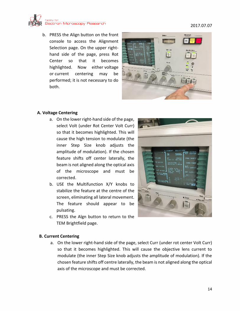
b. PRESS the Align button on the front
console to access the Alignment
Selection page. On the upper right-
hand side of the page, press Rot
Center so that it becomes
highlighted. Now either voltage
or current centering may be
performed; it is not necessary to do
both.
A. Voltage Centering
a. On the lower right-hand side of the page,
select Volt (under Rot Center Volt Curr)
so that it becomes highlighted. This will
cause the high tension to modulate (the
inner Step Size knob adjusts the
amplitude of modulation). If the chosen
feature shifts off center laterally, the
beam is not aligned along the optical axis
of the microscope and must be
corrected.
b. USE the Multifunction X/Y knobs to
stabilize the feature at the centre of the
screen, eliminating all lateral movement.
The feature should appear to be
pulsating.
c. PRESS the Algn button to return to the
TEM Brightfield page.
B. Current Centering
a. On the lower right-hand side of the page, select Curr (under rot center Volt Curr)
so that it becomes highlighted. This will cause the objective lens current to
modulate (the inner Step Size knob adjusts the amplitude of modulation). If the
chosen feature shifts off centre laterally, the beam is not aligned along the optical
axis of the microscope and must be corrected.

2017.07.07
15
b. Use the Multifunction X/Y knobs to stabilize the feature at the centre of the
screen, eliminating all lateral movement. The feature should appear to be
pulsating.
c. PRESS the ALGN button to return to the TEM Brightfield page.
11. Centering the Objective Lens Aperture Note: A specimen must be in place to perform this procedure. Choose an area that is
acceptable to sustain beam damage.
a. RETRACT the Objective Aperture, SET the magnification to 5,800x and OVERFOCUS the
beam by turning the Intensity knob clockwise from crossover.
b. SET the focus step size (inner Step Size knob) to 5 and PRESS the D button to put the
microscope in diffraction mode.
c. If necessary, ADJUST the Camera Length to 620 mm using the MAG knob. [Note that you
can accidentally choose 6.2 m rather than 620 mm.]
d. CENTRE the diffraction spot using the Multifunction X/Y knobs.
e. USING the focus (outer Step Size) knob, REFOCUS the beam to the smallest, brightest
spot. It may also be necessary to adjust the Intensity knob.
f. INSERT the Objective Aperture by ROTATING the aperture displacement lever below it to
the left. 7. Apertures may be selected by rotating the largest knurled knob on the
objective aperture assembly to any one of four numbered positions. (The Aperture
Memo lists the diameters and positions of the apertures currently installed in the CM200.
It may be accessed from the TEM BRIGHTFIELD page by PRESSING the Modes key and
then Configuration.)
g. Once the aperture has been selected, CENTRE it with both the smaller knurled knob in
the series on the aperture assembly and the small knurled knob to the right. Note: Do
NOT manipulate the small, innermost knob, which is not knurled and will unscrew the
aperture rod.
h. PRESS the D button again to exit Diffraction mode.
12. Correcting Objective Lens Astigmatism Two methods are possible:
A. Using the CCD Camera Live Fast Fourier Transform (Live FFT)
a. SELECT an area of the carbon film on the TEM grid
b. CHANGE the Magnification to 580,000x
c. PRESS the Lift Screen button
d. ACQUIRE a Live Image with the CCD camera.
e. Under the Camera Control, SELECT FFT

2017.07.07
16
f. UNDERFOCUS the image with the Focus knob (turn counter clockwise from the
crossover) to obtain a few Thon
rings.
g. PRESS the Stg button to OPEN
the Stigmator Control page. If it
is not already highlighted, PRESS
the Obj key on this page.
h. With a live image on the CCD
camera, adjust the shape of the
Thon rings until round using the
objective stigmator with the
Multifunction X and Y knobs.
B. Using the Image on the Fluorescent Screen
a. SELECT an area that may be imaged at high magnification without damaging any
desirable portions of the specimen. Increase the magnification to 175,000x or higher
and adjust the illumination so the substructure or background grain i.e carbon support
film may be observed easily. The Intensity will have to be modified and the electron
beam recentered using the Shift X/Y knobs (Deflectors) as the magnification is
increased. This latter function may alternatively be controlled using the RST button,
on the panel to the left of the column.
b. SET the Focus Step size to 2 and OBTAIN a slightly underfocused image for maximum
contrast.
c. PRESS the Stig button to
open the STIGMATOR
CONTROL page. If it is
not already highlighted,
press the OBJ key on
this page.
d. USE the Multifunction
X/Y knobs, one at a
time, to obtain the
sharpest possible image
of the grain
substructure.
e. VERIFY any astigmatism
has been corrected by
varying the focus (back

2017.07.07
17
and forth through focus, from underfocus to overfocus) and observe if a "streaking"
pattern emerges and changes direction between under- and overfocus. If the astigmatism
has been corrected, the specimen will vary only in focus, with no streaking pattern
evident. Repeat steps 4 and 5 until this state is achieved.
f. PRESS the Stig button again to return to the TEM Brightfield page.
13. Collecting Spectra with EDAX EDS and Genesis Software A. Collect spectra
a. DOUBLE CLICK on the EDAX Genesis icon on the PC desktop to open the program. b. TILT the goniometer
by +15°. c. It is important to
optimize the counts per second (CPS) and dead time (DT).
d. To change the CPS, change the Spot Size. Spot Size 6 is recommended.
e. Generally, to change the DT, adjust the Amp Time. DT should be between 20 to 40%. As a rule of thumb, SELECT an Amp Time of 25.6 or 51.2 µs.
f. FOCUS the image. g. RETRACT the Objective Aperture. h. PRESS the Clear button to remove old peaks. i. PRESS the Collect button to start to collect a new spectrum. To STOP the collection,
PRESS Collect again.

2017.07.07
18
j. For a fixed collection time, SELECT the Preset dropdown menu on the right-hand side of the Toolbar. Select a spectrum collection time in seconds either from the presets or by typing in a value.
k. In the adjacent dropdown menu, SELECT a Time Option: Clock Time, Live Time or ROI Counts. Clock time refers to actual time passed; live time refers to the actual time the detector is active. To use ROI Counts, ROIs must first be created. Refer to the EDAX manual for more detail. The live time setting is preferable for repeated measurements.
B. Peak identification a. To adjust the view of the spectrum, USE the expand (<> or ◊),
contract (>< or ∨) and home keys from the toolbar. The toolbar and these controls are shown in the figure below. The spectrum display may also be adjusted by clicking and dragging with the mouse.
b. PRESS Clear All in the spectrum collection panel to remove any old peak labels. c. PRESS the Peak ID button in the Spectrum Panel for automatic peak identification. The
primary peaks identified by the program will be labeled on the spectrum. d. PRESS HPD to display a theoretical spectrum, based on the identified peaks and the
collection parameters, on top of the collected spectrum. HPD is used to confirm if the correct elements have been identified.
e. For manual peak ID, PRESS the ◊ symbol to expand the panel. There are several ways to manually identify peaks.
f. With the mouse, CLICK ON a peak of interest. A list of possible elements will be displayed. The most likely peaks are at the top of the list. Scroll through the list and

2017.07.07
19
select an element to display the spectrum peaks on top of the collected spectrum. CLICK Add to add the element to the Elements list.
g. To remove an element from the Elements list, HIHLIGHT it and CLICK Delete. h. The Z+ and Z- buttons can be used to scroll through the elements. i. Check or uncheck the Alpha lines only, elem, shell, and trans boxes to change how
peak labels are displayed. j. CLICK on the ◊ symbols to hide the panel. k. To view the original spectrum without overlays, right CLICK with the mouse cursor in
the spectrum window. l. Known elements can be entered in the text box. PRESS enter to display the spectrum
peaks for that element on top of the collected spectrum. CLICK Add to add the element to the Elements list.
C. Saving Spectra
a. The spectrum is saved by CLICKING the Save button at the bottom of the Spectrum Panel. If you use the .spc as the extension, all the spectrum information will be saved and can be reanalyzed at a later time. It is recommended that you save all your work with this format.
b. To save an image of the spectrum, Save As using the .tif extension. c. When completed, close the program.
14. Changing samples
a. SELECT the TEM Brightfield page. b. PRESS the CompuStage button c. PRESS the Compuctrl button d. PRESS Reset Holder button e. REMOVE the Sample Holder (see Section 2A)
15. End of Session
A. Leave the microscope in the standard condition for the next user.
a. VERIFY the column valves are CLOSED.
b. VERFIFY the viewing screen is down; COVER the window with the rubber mat.
c. SELECT the TEM Brightfield page.
d. PRESS the CompuStage button
e. PRESS the Compuctrl button
f. DECREASE the Filament Current to 5
g. CHANGE the Magnification to 8200×. This is essential to maintain stable objective
lens current and prevent thermal drift for the next user.
h. RESET the stage.

2017.07.07
20
i. REMOVE the sample holder. RETRIEVE your TEM grid. REINSERT the holder into the
CompuStage/column of the microscope.
j. CHECK the Scheduler to determine if there is another user after you.
k. If you are NOT the last user of the day, refill the LN2 dewar.
B. If you are the last user of the day:
a. REMOVE the LN2 anti-contaminator dewar, pour the remaining LN2 into the large
dewar, and PLACE the microscope dewar on the counter. PLACE a towel below the
dewar platform to collect condensing moisture.
b. On the CRT, GO to the Vacuum page, PRESS the Cryo key, SET the time for six hours
and PRESS the Start key.
C. Retrieving Images from the Support PC (SPC). Note: Files are deleted on the SPC every
three months.
a. COPY your images to a USB drive, LOG OFF the SPC and TURN OFF monitors.
b. CLOSE the AMTv600 program and LOG OUT of the PC.
c. TURN OFF the Panel light with the Panel Dim knob and CRT Screen with the Data Dim
knob.
D. Last Steps
a. SIGN the logbook and LEAVE any relevant comments. If you START the cryo cycle,
please INDICATE in the comments.
b. TURN OFF any lights.
c. EXIT the room and CLOSE the door.

2017.07.07
21
Notes:
Camera Constant Lλ for SAED
For L=240 mm, Lλ=73.6 mmÅ
For L=340 mm, Lλ=104.1 mmÅ
For L=470 mm, Lλ=146.4 mmÅ
For L=700 mm, Lλ=204.4 mmÅ
Camera Constant Lλ for NBD
For L=240 mm, Lλ=57.5 mmÅ
(Note that you MUST print out the diffraction pattern in FULL SIZE)