electrical/efi service manual -...
TRANSCRIPT
Electrical/EFI Service Manual
ATV and Motorcycle
P/N : 5002401
August 14, 2002

INTRODUCTION
ABOUT THE MANUAL
All the procedures in this manual are organized in a numbered (step-by-step) easy to read format with accompa-nying photographs, line art, torque values and specifications. The numbered steps of a few procedures are likelyto be separate procedures themselves. When this is the case, the numbered step will include a page referencenumber.
COMMENTS?
Send your comments to: Cannondale Corporation, Technical Publications, 2 Corporate Drive, Bedford, PA 15522
Or e-mail: [email protected]
IMPORTANT NOTICE
You must possess significant mechanical knowledge, skills, and tools to perform most of theprocedures found in this document.
This manual is written for Cannondale Motorsports Dealers and qualified service technicians.
This is not a comprehensive shop safety manual and should not be used by anyone who is notfamiliar with standard safety practices and service techniques. This manual does includewarnings and cautions (see descriptions above) that if ignored, could result in SEVERE PERSONAL INJURY to the service technician or significant damage to the vehicle ren-dering it unsafe to operate. Anyone operating an “unsafe” vehicle can be SERIOUSLY INJUREDOR KILLED.
We have done our best to identify situations where warnings or cautions are needed and willcontinue to do so in future publications. But, YOU must always exercise good judgement, andfollow safe shop practices when performing service procedures as described in this manual.
This manual was accurate at the time of publication. Any supplemental information developedor written after printing may be available on our web site as a “manual supplement.” Service bul-letins and technical notes are also published as required. These are also posted on the website.
You may find that the technical terms and part names in this manual differ from published partscatalogs or microfiche.
3 8/14/02
3

IMPORTANT MANUAL INFORMATION
FAILURE TO FOLLOW THE WARNINGS CONTAINED IN THIS MANUAL CAN RESULT IN SERIOUS INJURYOR DEATH.
Information important to your safety is distinguished in this manual by the following notations: \
The safety alert symbol means......“ATTENTION! BECOME ALERT! YOUR SAFETY ISINVOLVED.”
Indicates that DEATH or severe injury WILL result if theinstructions are not followed.
Indicates a potential hazard that could result in seriousinjury or death.
A CAUTION indicates that special precautions must betaken to avoid damage to the machine.
A NOTE provides helpful information intended to makemaintenance easier or the instructions presented clearer.
DANGER
WARNING
CAUTION :
NOTE:
© 2002 Cannondale Corporation - All Rights Reserved4
Electrical_EFI Service Manual.fm

CONTENTS
INTRODUCTION - - - - - - - - - - - - - - - - - - - - - - 3Important Notice - - - - - - - - - - - - - - - - - - 3About the manual - - - - - - - - - - - - - - - - - 3Comments? - - - - - - - - - - - - - - - - - - - - 3
IMPORTANT MANUAL INFORMATION- - - - - - - - - - - 4
ENGINE MANAGEMENT SYSTEM (EMS) - - - - - - - - - 6Engine Control Unit (ECU) - - - - - - - - - - - - - 6ECU Programming - - - - - - - - - - - - - - - - - 7Servicing connectors and couplers - - - - - - - - - 9Barometric pressure sensor - - - - - - - - - - - 10Throttle position sensor (TPS) - - - - - - - - - - 10Coolant temperature sensor - - - - - - - - - - - 12Air temperature sensor - - - - - - - - - - - - - - 12Crankshaft position sensor - - - - - - - - - - - - 13Idle Air Control Valve (IACV) - - - - - - - - - - - 14Ignition coil - - - - - - - - - - - - - - - - - - - - 15EMS Power Relay - - - - - - - - - - - - - - - - 15Fuel pump and fuel pressure regulator - - - - - - 17Cooling Fan (ATV - - - - - - - - - - - - - - - - 20
CANNONDALE DIAGNOSTIC AND MAINTENANCE TOOL VERSION 2.0 - - - - - - - - - - - - - - - - - - - - - - - 21
General Information - - - - - - - - - - - - - - - 21Installation - - - - - - - - - - - - - - - - - - - - 21In the Windows Explorer, double click the SecurityCode
application. Or, you can access this application by clicking on Security code.exe through the program group. - - 22
Common Problems- - - - - - - - - - - - - - - - 23Interpreting Error Messages - - - - - - - - - - - 24Other Messages - - - - - - - - - - - - - - - - - 25Communication cable - - - - - - - - - - - - - - 27Cannondale Diagnostic and Maintenance tool Main Win-
dow - - - - - - - - - - - - - - - - - - - - - - - - 28ECU Operating code - - - - - - - - - - - - - - - 29Calibrations - - - - - - - - - - - - - - - - - - - 37ECU Monitor - - - - - - - - - - - - - - - - - - - 39Reading Fault Codes - - - - - - - - - - - - - - - 40
FAULT TROUBLESHOOTING - - - - - - - - - - - - - - 42Sensor Supply Voltage - - - - - - - - - - - - - - 42System Voltage - - - - - - - - - - - - - - - - - 43Fuel Pump - - - - - - - - - - - - - - - - - - - - 44Ignition Coil - - - - - - - - - - - - - - - - - - - 45Cooling Fan (ATV Only) - - - - - - - - - - - - - 46Fuel Injectors - - - - - - - - - - - - - - - - - - 47Throttle Position Sensor (TPS) - - - - - - - - - - 50Air temperature Sensor- - - - - - - - - - - - - - 51Coolant Sensor - - - - - - - - - - - - - - - - - 53Idle Air Control Valve (IACV) - - - - - - - - - - - 55Crankshaft Position Sensor- - - - - - - - - - - - 56
COMPONENT TESTING (NON-EFI)- - - - - - - - - - - - 57Battery - - - - - - - - - - - - - - - - - - - - - - 57Rectifier /Regulator- - - - - - - - - - - - - - - - 57Flywheel - - - - - - - - - - - - - - - - - - - - - 58Start Button (ATV & Motorcycle) - - - - - - - - - 58Engine Stop Button- - - - - - - - - - - - - - - - 58
Engine Stop Switch (ATV) - - - - - - - - - - - - 59Clutch Lever Switch (ATV) - - - - - - - - - - - - 59Key Switch - - - - - - - - - - - - - - - - - - - - 59Starter Solenoid - - - - - - - - - - - - - - - - - 59Starter Motor - - - - - - - - - - - - - - - - - - - 60Fuses - - - - - - - - - - - - - - - - - - - - - - 60
5 8/14/02
5

ENGINE MANAGEMENT SYSTEM (EMS)
Engine operation is supported by the managementsystem consisting of three main types of electricalcomponents: the ECU, the sensors, and the actu-ators.
• The engine control unit (ECU or ECM) preciselycalculates ignition timing and fuel delivery for allengine speeds and loads (based on thecurrently installed calibration file and itsmapping). The ECU is an extremely reliablecomponent and should be the last componentchecked in the event there is a problem with thefuel injection system.
• The sensors of the system collect engineoperating information and transmit it to theECU.
• The actuators are devices like the fuel injectors,fuel pump, fuel pressure regulator, and sparkplug coil, and relays.
ENGINE CONTROL UNIT (ECU)
The engine control unit or “ECU” is a kind of com-puter that calculates ignition timing and fuel deliveryfor all engine speeds and loads based on its pro-gramming. It is sometimes referred to as the “brain”of the fuel injection system. This brain calculates fueldelivery and ignition timing based on informationgathered from vehicle sensors (inputs) and the cali-bration file loaded at the factory.
The ECU inputs are the air temperature, coolant,crankshaft position, throttle position, and barometricpressure sensors. Information from these sensorstogether with the ECU operating code (hex file) andengine calibration file (map) are used to control thesystem actuators (e.g. fuel pump, ignition coil,injectors, relays, idle air control valve).
NOTE :In this manual, the engine control unit is referredto as the “ECU.” It is also sometimes called an“ECM” or engine control module. Either referenceis OK.
Motorcycle ECUs are located within the subframe.
ATV ECUs are located on the electronics tray underthe cowl.
1. ECU2. Air pressure sensor hose (from airbox and fuel pressure
regulator)3. Internal barometric (air) pressure sensor.
1. ECU2. Air pressure sensor hose (from airbox)3. Accessories connector4. EMS power relay
1
2
3
2
3
3
4
1
© 2002 Cannondale Corporation - All Rights Reserved6
Electrical_EFI Service Manual.fm

ECU PROGRAMMING
The ECU is “programmed” with three types of infor-mation. the operating code (also known as the “hex”file, the engine calibration file (also known as the“map”), and the vehicle variables or “calibrations.”Calibrations are stored in the map file but are specificto the throttle body and injectors installed on thevehicle.
Any programmed information can be changed.using the Cannondale Diagnostic and MaintenanceTool. Refer to "Cannondale Diagnostic and Mainte-nance Tool Version 2.0" starting on page 21.
ECU diagnostic connectors
ATVs and motorcycles have a diagnostic con-nector to connect the software tool PC to the vehicle.
• On 2001 and 2002 Motorcycles, the diagnosticconnector is located near the ignition coil on thetop of the cylinder head.
• On 2003 motorcycles, the diagnostic connectoris located near the main fuse under the seat.
• On 2001 - 2003 ATV the diagnostic connector islocated near the radiator shroud on the left side
of the ATV.
The tool is a combination of a specially developedWindows- based software program and a data cableused to connect your PC or pocket PC computer toyour vehicle. With the tool, you can read fault codes,install engine calibration files, set vehicle rpm, andmonitor engine operating parameters.
Reporting system faults
The ECU is capable of reporting system hardwaremalfunctions during operation. It reports currentproblems and does not store problem “faults” inmemory.
System faults are read from the ECU using theCannondale Diagnostic and Maintenance Tool, aWindows-based PC program enabling communi-cation between a PC and the vehicle ECU. The ECUdoes not store intermittent faults; the faults reportedare occurring at the moment when the ECU FaultReport window is selected in the software tool. Aspecial communication cable is needed to connectthe vehicle to a PC. Refer to "Cannondale Diag-nostic and Maintenance Tool Version 2.0" starting onpage 21.
This manual provides step-by-step fault diagnostictesting based on the actual fault reported by thesoftware tool. Refer to "Fault Troubleshooting"starting on page 42.
1. Diagnostic connector2. EMS power relay3. Main fuse
31
2
7 8/14/02
7

P1 and P2 Connectors
MC1000 ECUs have two main harness connectorsockets.
Remove both main harness connectors from theECU when performing pin point tests described inthis manual.
Also, if required, be sure to disconnect any otherdevices; see the specific pin point tests.
• Connector P1 color is black. It connects to theblack ECU socket.
• Connector P2 color is grey. It connects to thegrey ECU socket.
CAUTION :
Allow connector rotating latch to draw theconnector into the ECU socket (coupler). Do notpress or force the connector; it should slideinto the socket easily.
Check for contamination and pin conditionbefore reconnecting.
Lubricate the connector seals with a high-quality dielectric grease before reinstalling.
Use a commercially available pin gauge whenperforming pin point tests. Ordinary testerprobes can spread pins resulting in looseconnections.
Pin identification (P1 or P2)
Use the following illustration for P1 and P2 pin iden-tification.
Disconnecting the ECU
1. Disconnect the battery.
2. Press in the latch locking tab and rotate the latchin direction (a) until it stops. Pull the connectorfrom the ECU socket.
Reconnecting the ECU
1. Make sure the battery is disconnected.
2. Make sure the main fuse is removed.
This photo shows how to identify individual pins in the ECUharness connectors. Each row is identified by a number 1-4.Each column is identified by a letter A - H.
1. Latch2. Locking tab
HH BG F E D AC
H BG F E D AC
1
2
3
4
a
1
1
© 2002 Cannondale Corporation - All Rights Reserved8
Electrical_EFI Service Manual.fm
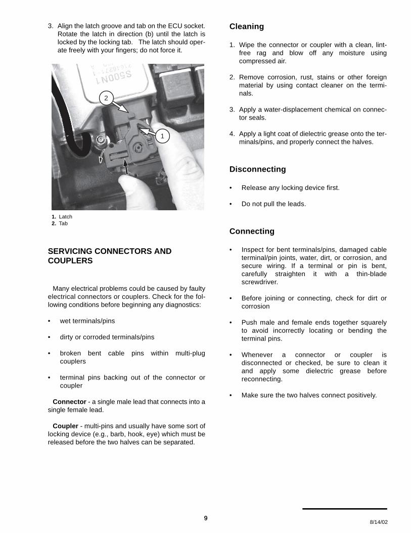
3. Align the latch groove and tab on the ECU socket.Rotate the latch in direction (b) until the latch islocked by the locking tab. The latch should oper-ate freely with your fingers; do not force it.
SERVICING CONNECTORS AND COUPLERS
Many electrical problems could be caused by faultyelectrical connectors or couplers. Check for the fol-lowing conditions before beginning any diagnostics:
• wet terminals/pins
• dirty or corroded terminals/pins
• broken bent cable pins within multi-plugcouplers
• terminal pins backing out of the connector orcoupler
Connector - a single male lead that connects into asingle female lead.
Coupler - multi-pins and usually have some sort oflocking device (e.g., barb, hook, eye) which must bereleased before the two halves can be separated.
Cleaning
1. Wipe the connector or coupler with a clean, lint-free rag and blow off any moisture usingcompressed air.
2. Remove corrosion, rust, stains or other foreignmaterial by using contact cleaner on the termi-nals.
3. Apply a water-displacement chemical on connec-tor seals.
4. Apply a light coat of dielectric grease onto the ter-minals/pins, and properly connect the halves.
Disconnecting
• Release any locking device first.
• Do not pull the leads.
Connecting
• Inspect for bent terminals/pins, damaged cableterminal/pin joints, water, dirt, or corrosion, andsecure wiring. If a terminal or pin is bent,carefully straighten it with a thin-bladescrewdriver.
• Before joining or connecting, check for dirt orcorrosion
• Push male and female ends together squarelyto avoid incorrectly locating or bending theterminal pins.
• Whenever a connector or coupler isdisconnected or checked, be sure to clean itand apply some dielectric grease beforereconnecting.
• Make sure the two halves connect positively.
1. Latch2. Tab
1
2
9 8/14/02
9

BAROMETRIC PRESSURE SENSOR
The barometric pressure sensor is housed withinthe ECU. Air pressure within the airbox is transferredto the ECU by a narrow hose. Air pressure infor-mation is used to adjust the amount of injected fuel tomatch the prevailing conditions. The sensor is notuser serviceable. If no external problems are foundwith the hose or the hose routing end points, and abarometric pressure sensor fault persists, the ECUwill have to be replaced.
NOTE :When performing tests, start by checking the hoserouting from the ECU to the airbox. The routingmay be interconnected with other devices. Be sureto check all vacuum/pressure routing hoses fordamage.
Dynamic Test - ECU Monitor
1. To test, determine the barometric pressure atelevation in the operating area.
2. Read the reported sensor data with the Cannon-dale Diagnostic and Maintenance Tool. This valueis reported at the “Airbox Pressure (kPa)” field inthe ECU Monitor window. Refer to "ECU Monitor"starting on page 39.
3. Compare the known value with the one reportedby the software tool. If the comparison of theactual value and the reported value results in awide disparity, and no other faults are present andengine trouble remains, consider replacing theECU.
NOTE :When comparing the actual barometric pressurereading and the one reported through thesoftware, be sure to convert to equivalent units(kPa).
THROTTLE POSITION SENSOR (TPS)
The throttle position sensor (TPS) is a rotary poten-tiometer attached to the end of the throttle plate shafton the right side of the throttle body.
Fueling requirements are calculated by the ECU forchanging throttle positions.
The fully closed and fully open throttle positions(interpreted by the minimum and maximum voltageread through the sensor) are stored as numericvalues in the ECU.
NOTE :Anytime the throttle body is serviced or the sensoris removed or replaced, the min/max values mustbe re-read into the ECU using the UpdateCalibrations window of the tool.
Use the Cannondale Diagnostic and MaintenanceTool.
Refer to "“Throttle Body Leakage” (also calledThrottle Body Offset) (Input range 0 - 100) Theequivalent amount, in percent, of throttle opening
1. TPS Sensor2. Throttle Body3. Harness connection point
2
1
3
© 2002 Cannondale Corporation - All Rights Reserved10
Electrical_EFI Service Manual.fm

required on a “perfect” throttle body to match theair flow of the vehicle's throttle body at the closedposition. Typical values are from 0.0 to 1.0%"starting on page 37.
The TPS sensor signal informs the ECU of not onlythe relative position of the throttle plate, but also thespeed with which it is being opened or closed. Theengine load is determined by the TPS and enginespeed (rpm). The voltage output from the TPSincreases proportionately as the throttle is opened.The sensor contains no user serviceable items.
Dynamic Test - ECU Monitor
1. Use the ECU Monitor windows of the CannondaleDiagnostic and Maintenance Tool and read theThrottle position (%) field. This field is the percentthe throttle plate is open as translated by theECU. With the throttle plate completely closed,this value should read between 2% to 3%. Whenthe throttle is fully opened, a normal reading is97% to 100%. When the idle adjustment is set,this value should be approximately 3% higherthan the completely closed percent to achieverough idle. Fine tuning of the idle adjustmentscrew which changes the% percent may berequired
If the Throttle Position (%) field values in the ECUmonitor window are erratic or inconsistent asdescribed above, the sensor can be tested furtherby removing it and reading the resistance valueswith an Ohmmeter.
2. Attach a vacuum pump/pressure pump to thehose end and monitor change. The readingshould increase when increased pressure isapplied. The reading should decrease when vac-uum is applied.
NOTE :Be sure to convert the atmospheric pressure unitsdisplayed in the ECU monitor window with unitsdisplayed with the tools.
CAUTION :
Use of high pressure or vacuum when testingmay damage the sensor diaphragm.
Static Test - Resistance
1. To test the sensor resistance, remove the sensorharness connector, remove the mounting bolts,and remove the sensor from the throttle body.
NOTE :Removing the sensor from the throttle plate shaftto measure the resistance is not required.Removing it and inspecting the housing and shaftsocket for damage can be helpful. Remember thatis the sensor is removed, you will have to reset thesensor min and max values using the softwaretool. Refer to "Setting the throttle position sensorminimum and maximum values" starting onpage 34.
2. Measure resistance across sensor terminals Aand B.
The resistance should be 1200 ± 240 Ohms.
3. Measure the resistance across sensor terminalsA and C.
- slowly rotate the sensor wheel clockwise andobserve variable resistance. Resistance shouldincrease smoothly from 0 to 1200 ± 240 Ohms.
1. TPS sensor (shown removed)
1
11 8/14/02
11

COOLANT TEMPERATURE SENSOR
The coolant temperature sensor is brown in colorand located on the front of the engine cylinder head.It is an NTC thermistor.
The ECU measures the current flow through thisthermistor to ground and uses it to determine theengine coolant temperature. The ECU calculatesfueling to optimize engine performance at all temper-atures. It also calculates hot and cold start fuelingrequirements.
The sensor resistance decreases as the temper-ature increases.
Dynamic Test - ECU Monitor
1. Starting with a completely cool engine, use theECU Monitor window of the CannondaleDiagnostic and Maintenance Tool to read theEngine Temperature (degC) field in the ECUMonitor window. Refer to "Using the ECUMonitor" starting on page 39.
2. Open the radiator cap and test the coolant tem-perature with a thermometer.
3. Compare the values. If the two values do not cor-respond closely, the sensor may be damaged. Goto the next step.
4. Be sure to replace the radiator cap and start theengine and allow to reach operating temperature(60°C). Observe the Engine Temperature (degC)field in the ECU Monitor window. If the value doesnot increase as the engine warms, go to the nexttest.
Static Test - Resistance
1. Disconnect the sensor harness connector.
2. Use an Ohmmeter to measure the sensor resis-tance between terminals 1 and 2. Refer to "Cool-ant Sensor Resistance Range" starting onpage 54. If measured resistance is inconsistent atthe tested temperature replace the sensor. If thesensor is OK, the sensor harness wiring or theECU itself may be damaged. Take correctiveaction.
AIR TEMPERATURE SENSOR
The intake air temperature sensor is attached to theairbox with the tip mounted inside the airbox.
It is a NTC thermistor and green in color.
Resistance will drop as temperature rises.
The sensor tip is very sensitive to temperaturechange.
CAUTION :
The tip can be damaged easily; use extra carewhen installing or working inside the airbox.
The ECU uses the information from this sensor tocalculate the fuel necessary for a given air temper-ature.
Dynamic Test - ECU Monitor
1. Use the ECU Monitor window of the CannondaleDiagnostic and Maintenance Tool to read theEngine Temperature (degC) field in the ECUMonitor window. Refer to "Using the ECUMonitor" starting on page 39.
1. Coolant temperature sensor (ATV shown)
WARNING
Never open the coolant system when theengine is hot. Coolant is hot and underhigh pressure. It can spray out forcefullyand burn or scald you severely.
1
© 2002 Cannondale Corporation - All Rights Reserved12
Electrical_EFI Service Manual.fm

2. Compare the value with a reading taken manuallyin the vicinity of the air temperature tip. If the twovalues do not correspond closely, the sensor maybe damaged.
Static Test - Resistance
1. Remove the sensor from the airbox by placing anopen-end wrench on the sensor body and turningit counter-clockwise until it can be removed.
2. Measure the sensor resistance between terminals1 and 2. Refer to "Air Temperature Sensor Resis-tance Range" starting on page 52.
If the measured resistance is inconsistent at thetested temperature, replace the sensor.
If the measured resistance closely matches thetable values, the sensor is OK, the sensor har-ness wiring or the ECU itself may be damaged.Take corrective action.
CRANKSHAFT POSITION SENSOR
SERVICE: Crankshaft position sensor gap0.02 - 0.03 in (0.5 -1.0 mm)
The crankshaft position sensor is located in thegenerator housing.
This sensor detects movement of a toothed wheelthat is molded into the flywheel and attached to theright side of the crankshaft. The wheel has a 36-toothpattern. The flywheel teeth are evenly spaced withthe exception of one, triple-length tooth next to one,triple-length gap. Everytime this tooth/gap passes thesensor, the ECU interprets it as bottom dead center(BDC). The ECU uses this information to determineengine speed and crankshaft position in relation tothe point where fuel is injected and ignition of the air/fuel mixture occurs.
If the crankshaft position sensor malfunctions, theengine will not start. If the sensor tip is contaminatedwith metallic debris, oils and dirt, or incorrectlygapped, the engine can run erratically.
If the flywheel is damaged, the sensor may be ok,but may be reading bad information due to theresulting change in the indexing between the crank-shaft and flywheel teeth. Refer to "Flywheel" startingon page 58.
NOTE :Metallic debris or other contaminants on thesensor tip will affect the sensor.
Inspection points
1. Ensure sensor connection to harness is secure.
2. Check sensor gap: 0.5mm-1.0mm.
3. Check for magnetic debris on sensor tip.
4. Check for damaged flywheel teeth.
5. Check flywheel for run-out or play.
6. Check flywheel hub for cracking or separation.
Dynamic Test - ECU Monitor
1. Use the ECU monitor window to confirm changein reported engine rpm.
With the engine off, there should be no readingdisplayed at engine rpm field.
Crank the engine over and a reading should bedisplayed. If no change is observed, the sensor orharness circuit is faulty. Take corrective action.
The flywheel cover has been removed for this photo to show thesensor tip.
1. Crankshaft position sensor2. Sensor tip3. Flywheel tooth4. Gap
1
2a
13 8/14/02
13

Static Test - Resistance
1. Disconnect the sensor harness connector.
2. Use an Ohmmeter to measure the sensor resis-tance between terminals 1 and 2.
SERVICE: Crankshaft position sensor resistance range - 532 TO 588 Ohms
IDLE AIR CONTROL VALVE (IACV)
The Idle Air Control Valve (IACV) is an ECU con-trolled valve mounted on the throttle body.
As soon as the ECU is powered up, this valvebegins to move to the correct position (increasing ordecreasing the available air bypass volume neededfor cold start). The ECU controls the valve armdepending on engine temperature. The valve armmoves in “steps” that extend or retract the valve arminside the bypass housing.
The arm travels.024mm per step.
Total travel = 0 to 255 steps
In a cold engine, the valve opens (arm retracts)allowing more air to bypass the throttle plate. As theengine warms up, the valve closes (arm extends)until the bypass channel through the housing is com-pletely shut at 60°C.
Here are some symptoms of a faulty IACV
• Hard starting - the valve arm could be stuckshut. In this case, the extra air needed for coldstarting conditions is not available. Enough airmay be available to start a warm.
• Engine idles too fast - valve is stuck open.
• Rough idle - if the valve arm is malfunctioning
Dynamic Test 1 - ECU Monitor
1. Make sure the engine is completely cool.
2. Use the Cannondale Diagnostic and MaintenanceTool to read current valve stepped position withthe cool engine.
Read the valve position at IACV Stepper Positionfield in the ECU Monitor window. Refer to "Usingthe ECU Monitor" starting on page 39.
NOTE :Make sure the monitor is in “continuous” mode.
3. Start the engine and allow to it idle normally.Observe the IACV Stepper Position and EngineTemperature (degC) fields. As the engine temper-ature climbs, the IACV Stepper Position shouldincrease indicating that the arm is extending andthe bypass channel inside the housing reducing.At engine operating temperature (60°C) the armshould be fully extended and the bypass closed.
4. If no change is observed, go to Dynamic Test 2.
Dynamic Test 2 - Confirm arm movement
1. Make sure the vehicle engine is completely cooland press the engine stop button to ensure thatthe ECU is powered down.
2. Remove the bypass housing from the throttlebody with the IACV valve attached to it.
1. Idle Air Control Valve (IACV)
IACV Stepped positions
Fully Open Fully Closed (at 60°C)
175 205
1
© 2002 Cannondale Corporation - All Rights Reserved14
Electrical_EFI Service Manual.fm

CAUTION :
Do not remove the valve from the housing whenperforming this test.
3. Disconnect the engine coolant sensor.
4. Reconnect the idle air control valve to the har-ness.
5. Press the engine start button quickly without turn-ing over the engine. The valve should extend fully.
6. Reconnect the coolant sensor and observe move-ment of the valve arm; the valve should retractslightly.If the valve does not move, replace it with a newone.
Static Test - Resistance
1. Remove the valve mounting screws and removethe valve from the bypass housing.
2. Inspect the housing pintel seat and valve pintelend for damage.
3. Measure resistance across sensor terminals (A)to (D). The resistance should be 53 ± 10% Ohms.
4. Measure resistance across sensor terminals (C)to (B). The resistance should be 53 ± 10% Ohms.
IGNITION COIL
The ignition coil is a “pencil-type” coil located on topof the spark plug within the cylinder head.
The ECU controls when the coil is switched on oroff. The coil is switched on to allow sufficient time forthe coil to charge to a level where a spark can beproduced at the spark plug. The coil switches off atignition, which is timed for good engine performance.
Inspection Points
1. Check the coil body for damage (e.g., burning,cracks, discoloration (excessive heat).
2. Check the coil terminal pins. Make sure they arein good condition.
3. Check the condition of the tip insulator. Make sureit is not cracked, burned, melted, dried out.
4. Make sure the spring is installed with the largerend facing the coil.
Dynamic Test - Spark Occurrence
1. Disconnect the ignition coil from the harnessconnector.
2. Remove the retaining clip bolt and coil retainer.
3. Lift the ignition coil out of the cylinder head.
4. Reconnect the harness.
5. Insert a commercially available spark tester intothe end of the coil. Connect the ground lead of theindicator to the cylinder head.
6. Turn the ignition switch on and press the enginestart button. If spark is indicated, the coil is OK.
Static Test - Primary Resistance
1. Measure the resistance between the coil terminalpins.
EMS POWER RELAY
The EMS power relay supplies the ECU with powerwhen the vehicle start button is pressed and willremain locked when the engine is running. Therelay will hold for up to 2 minutes without the enginerunning or turning over, then it will drop power toECU.
WARNING
An energized ignition coil generates ahigh voltage spark capable of jumping to aground point. The following procedure willcreate a spark that can ignite any availablefuels. You can be seriously injured or killedin a resulting fire or explosion.Make sure the work area and vehicle arefree of any gasoline or flammable liquids(flooded engine, fuel tank, fuel hoses, sol-vents).
15 8/14/02
15

On motorcycles, if this relay is damaged, theengine can start but will shut down when the startbutton is released.
On ATVs, if this relay is damaged or removed, theengine will run, but damage to a harness diode willresult. When the diode fails, the engine will not run.
Dynamic Test
1. Remove the relay from its harness socket.
2. Using an ohmmeter, connect the positive probe(+) onto terminal number 86 and the negative (-) probe onto terminal number 85. Check theresistance. The resistance should be 1500 ± 10%Ohms.
Reverse the meter leads. If the reading is OL (nocontinuity), go to the next step.
If the relay is out of specification, replace the relaywith a new one. If the measured resistance is OK,go to the next step.
3. Using an Ohmmeter, connect the positiveprobe (+) onto terminal number 30 and thenegative (-) probe onto terminal number 87.Check the for continuity. There should be nocontinuity. If continuity is observed, the relayis damaged; replace it. If no continuity isobserved, go to the next step.
4. Connect 12 V (+) battery voltage to thenumber 86 terminal and ground terminal
number 85. There should be continuitybetween terminals 30 and 87. If there is not,the relay is damaged; replace it.
5. Use a voltmeter to verify that there is voltagepresent at the wiring harness socketcorresponding to relay terminal 87. Do notstart the engine. If there is no voltage present,check the main fuse. Use the vehicle wiringdiagram to check the circuit. Take correctiveaction.There are no markings on the socket itself;use the illustration below for identification.
NOTE :Wiring diagrams are available on our website.http://www.cannondale.com/motorsports/tech/servman.html
"30"
"85"
"87"
"86"
RELAY - P/N 5000411
30
86 8
5
87
12.5 VDC
SOCKET
© 2002 Cannondale Corporation - All Rights Reserved16
Electrical_EFI Service Manual.fm

NOTE :When the ignition switch is turned “ON,” theinstalled relay will make an audible “click.”
FUEL PUMP AND FUEL PRESSURE REGULATOR
The fuel pump and regulator maintain fuel supplyand pressure to the injectors. When the engine man-agement system is first “powered-up,” this pump acti-vates for 3 seconds to pressure the fuel system thenturns off again until the engine starts. When theengine starts, it resumes pumping, providing pres-surized fuel to the injectors. The regulator returnsfuel to the fuel tank.
NOTE :The positive (+) pump terminal is always “hot” -even with the ignition switch OFF. This terminal isconnected directly to the positive battery voltagethrough the main fuse. The pump is activated byECU switching the negative circuit to ground.Consult the vehicle wiring diagram for more detail.
The fuel pressure regulator maintains the correctfuel pressure in the fuel rail (hoses and injectors). Itreturns fuel to the tank after fuel passes the fuelinjectors. The regulator is connected to the airbox viaa small hose. On ATVs the fuel pressure regulator ismounted on the main frame on the right side of thevehicle (front).
Dynamic Test - Pump and Regulator
NOTE :If you suspect a problem with the fuel pump, firstcheck to see if it runs at all. Do the following:
Turn the ignition switch “ON” and listen to thepump, it should make a “whirring” sound for a fewseconds to pressurize the system - then the pumpwill turn off.Start the engine and allow the vehicle to idle. Youshould hear a constant whirring” sound - althoughit is more difficult to hear.
NOTE :The pump will turn anytime the start button ispressed on motorcycles, however, the pumpcircuit is different is different on ATVs. If the ECUhas not powered down, the pump will not turn onunless the clutch lever is pulled in and the startbutton is then pressed momentarily.
1. If the fuel pump does not turn on, check thefollowing:
Pump wiring terminals. Make sure they are clean
1. Fuel pump2. Fuel inlet (from tank)3. Fuel outlet (to injectors)
2
3
1
Components have been removed for this photo.
1. Fuel pressure regulator housing2. Fuel hose (from injectors)3. Fuel hose (return to tank)4. Air pressure hose (from airbox)
4
1
2
3
17 8/14/02
17

and the wiring is in good condition. Make sure theboots are in place.
Check for voltage at the pump when the startbutton is pressed. Check for any open or shortcircuit conditions in the fuel pump circuit. Consultthe vehicle wiring diagram. Take corrective actionif necessary.
Quick connect fuel fittings - Make sure the O-ringsare in good condition. Damaged O-rings canresult in pressure loss or the introduction of airinto the fuel lines reducing developed fuelpressure. The fittings have an internal andexternal O-ring. External O-rings can be checkedvisually. Fuel flow can be restricted or stop is theinternal O-rings are swollen or damaged.
2. Replace the fuel filter to assure adequate fuel flowto the pump.
CAUTION :
Do not perform this test with unfiltered fuel;severe damage can occur to the pump or fuelinjectors.
3. Fill fuel tank with the specified fuel as required.
4. Hold a clean rag around the regulator inlet andloosen the hose clamp to relieve any residual fuelsystem pressure.
5. Install a T-fitting and fuel pressure gauge betweenthe regulator inlet and hose coming from theinjectors. Make sure the return line attached tothe regulator outlet is connected to the fuel tank-tank.
6. Start the engine and read the generated fuel pres-sure.
If the fuel pressure reading is OK, the pump and
regulator are OK.
If the fuel pressure reading is low, quickly discon-nect and reconnect the fuel tank return line, if thefuel pressure reading increases when the returnline is disconnected, the regulator is faulty replaceit.
If the fuel pressure does not increase, replace thepump and regulator.
SERVICE: Fuel pressure
3.0 ±.25 bar
Dynamic Test - Voltage test
1. First, use a multi meter to check for batteryvoltage to the pump at the (+) fuel pump terminal.
2. Use an Ohmmeter. Connect the positive lead tomain harness connector CN16 pin B. Connect thenegative lead to ground. Have an assistant turnthe ignition switch “ON”. Press the engine startbutton and release it.
If there is continuity, the pump harness circuit isOK.
If there is no continuity, disconnect the ECU andcheck for continuity between CN16 pin B andECU connector pin P1 H1. There should be conti-nuity. Take corrective action and repeat step 2.
If no continuity is present between CN16 pin Band P1 H1 after the circuit is corrected, replacethe ECU (It is not switching the pump circuit toground).
WARNING
Gasoline is extremely flammable and isexplosive. Handle with extreme care!
When inserting a pressure gauge into thefuel system, make sure all hose connec-tion are secure. Make sure the fuel tankoutlet and inlet lines are connected prop-erly to the tank.
© 2002 Cannondale Corporation - All Rights Reserved18
Electrical_EFI Service Manual.fm

FUEL INJECTORS
ATVs and motorcycles utilize a pair of fuel injectorsthat operate (inject) simultaneously.
Pressurized fuel flows into the injectors from thefuel pump. The fuel is delivered into the intake portwhen the ECU sends voltage to the injector internalsolenoid. When the solenoid actuates, the pres-surized fuel sprays, through the nozzle.
The fuel injectors are positioned as close as pos-sible to the back of the intake valves. The spraypattern is fixed. The length of time duration that theinjectors stay open is calculated by the ECU usingthe calibration file and data received by the varioussensors.
Dynamic Test - Function
NOTE :The following procedure is based on theassumption that there is adequate fuel supply andpressure is available in the fuel rail.
1. Check the injector wiring harness connectors.Make sure they are secure.
2. Check that the battery is fully charged. The sen-sor and actuators of the system depend on accu-rate voltage readings to meter the fuel.
3. Check the air filter element. If it is dirty or blocked,this will severely impede air flow and fuel econ-omy.
4. Check the airbox and throttle body assemblies forpossible air leaks that would result in a leaning ofthe fuel mixture.
5. Use an automotive stethoscope to determine ifeach injector is working properly. You should heara steady clicking sound that rises and falls withthe engine speed.
If you hear nothing, use a commercially availablenoid light to test for voltage present at the harnessconnector.
NOTE :If you do not have a stethoscope, you can use ascrewdriver against the injector and listen throughthe handle.
Static Test - Resistance
1. Disconnect the injector, and test the resistance ofeach injector across the terminals. If theresistance value is out of specification, replacethe injectors as a pair.
SERVICE: Fuel, fuel injector, resistance11.75 to 12.75 Ohms
2. Install the injector test light (one at a time) into
Engine shown removed for clarity.
1. Left fuel injector2. Right fuel injector3. Fuel inlet (from fuel pump outlet)4. Fuel outlet (to pressure regulator)
1. Fuel injector (left or right)
1
3
2
4
TOP(FUEL ENTRY)
O-RING
NOZZLE(FUEL EXIT)
CONNECT
O-RING
1
19 8/14/02
19

each injector harness connector. Crank theengine over. If the light flashes evenly on eachconnector, voltage is available at the injectors.
3. If the light fails to flash for either injector, checkthe fuel injector wiring circuit for continuity. Con-sult the vehicle’s wiring diagram.
COOLING FAN (ATV
The positive (+) cooling fan terminal is always “hot,”- even with the ignition switch OFF. This terminal isconnected directly to the positive battery voltagethrough the main fuse.
NOTE :The ECU switches the negative side of the coolingfan circuit to ground when engine temperaturereaches the ON point. It breaks the ground contactwhen the temperature drops to the OFF point. TheON and OFF points are determined by the ECUoperating code.
Consult the vehicle wiring diagram for circuitdetails.
Static Test - Resistance
1. Disconnect the main harness connector from thecooling fan coupler.
2. Measure the resistance between the two fanleads. The resistance should be less than 1 Ohm;if it is go to the next test.
If it is more than 1 Ohm, replace the fan.
Dynamic Test - Operate
1. Disconnect the main harness connector from thecooling fan coupler.
2. Connect a 12 V (+) battery voltage source tothe red fan lead. Connect the 12V (-) lead tothe black fan lead. If the fan runs, it is OK.Check to make sure the airflow is correct;there is a flow direction indicator on the fanhousing. Airflow should be drawn throughthe radiator from the front of the vehicle to theback. Go to the next step.
If the fan does not operate normally (e.g.,stops and starts, or spins slowly or not at all),replace the fan.
3. Set the multi meter to VDC or Vdc (20 voltrange). Connect the positive meter probe to harnesscoupler CN22 pin A.Connect the negative meter probe to ground.Battery voltage should be present.
If battery voltage is not present, check themain fuse or connections to the battery. If themain fuse and battery connections are OK,Check for an open or short circuit in thecooling fan circuit. Consult the vehicle wiringdiagram. Take corrective action.
If the fan circuit is OK, check the coolantsensor.
If the coolant sensor is OK, replace the ECU.
Cooling Fan (ECU switching)
ON OFF
85°C 80°C
WARNING
Spinning fan blades can cause the fan tojump on the workbench possibly resultingin severe injury.If the fan is removed from the vehicle radi-ator, be sure to secure the cooling fan tothe work bench. And, position the fan sothat the blades can spin freely when ener-gized. Keep your hand clear of the bladesand wear eye protection.
© 2002 Cannondale Corporation - All Rights Reserved20
Electrical_EFI Service Manual.fm

CANNONDALE DIAGNOSTIC AND MAINTENANCE TOOL VERSION 2.0
This section of the manual describes how to usethe Cannondale Diagnost ic and Maintenancesoftware tool.
GENERAL INFORMATION
The Cannondale Diagnostic and MaintenanceTool, Version 2.0 is a Windows-based software appli-cation enabling communication with the vehicle ECU.
Use the tool for:
• Changing the ECU operating code or “hex” file.
• Installing a new engine calibration file.Refer to "Sending a calibration file or “map” tothe ECU - “Changing a map”" starting onpage 34.
• Receiving the current engine calibration filefrom the vehicle ECU to the PC.
• Set the vehicle throttle body and injectorvariables.
• Monitor the (vehicle) ECU operatingparameters.
• Read system faults.
A special interface cable is needed to connect thePC to the vehicle once the software is installed andauthorized for use.
INSTALLATION
Installing the software
1. Insert the installation CD into the CD drive of yourcomputer.
Right click on the Windows START button in thelower left corner of the screen.
Use Windows Explorer, click on the CD drivecontaining the Cannondale Dealer Cal softwareCD to view the file contents.
2. Double click on the Setup.exe application.
3. Follow the installation screens. When the setupprocess is complete, the Cannondale Diagnosticand Maintenance program group will be installedand a shortcut to the Cannondale Diagnostic andMaintenance tool will be placed on the your desk-top.
But, before you can use the software, you’ll needto complete the authorization process by makinga telephone call and typing in an authorizationnumber.
21 8/14/02
21

In the Windows Explorer, double click the SecurityCode application. Or, you can access this application by clicking on Security code.exe through the program group.
When the DealerCal window displays (see next illustration), call: Optimum Power Technology at 1-800-727-9520(Monday through Friday, (9 am to 5 pm EST) to obtain the security code needed to activate the software.
HERE
© 2002 Cannondale Corporation - All Rights Reserved22
Electrical_EFI Service Manual.fm

Enter the Serial provided by the service rep in theDealerCal window. Click Next.
Verifying COM port setup
Under Windows 95/98/2000/NT/ME:
1. Click ’Start’ button and select ’Settings->ControlPanel’.
2. From ’Control Panel’, Double-click ’System’.
3. From ’System Panel’, click ’Device Manager’ or’Hardware’ tab. If clicking ’Hardware’, click the’Device Manager’ Button.
4. Click the ’+’ next to ’Ports’ to expand the availableports detail. If there is a red ’X’ or a yellow ’!’ infront of the Communications Port, a problemexists with your Port Driver. Contact your Com-puter specialist to resolve the problem. If there isonly a connector icon, note the CommunicationsPort Name (COM1, COM3, etc.) Run your Dealer-Cal software. Under ’File->Change Port’ changeyour Active Port to the above CommunicationsPort Name. DealerCal will retain this setting.
Under Windows XP:
1. Click ’Start’ button and select ’Control Panel’.
2. From ’Control Panel’, Double-click ’Performanceand Maintenance’.
3. From ’Performance and Maintenance’, double-click ’System’.
4. From ’System Panel’, click ’Device Manager’ or’Hardware’ tab. If clicking ’Hardware’, click the
’Device Manager’ Button.
5. Click the ’+’ next to ’Ports’ to expand the availableports detail. If there is a red ’X’ or a yellow ’!’ infront of the Communications Port, a problemexists with your Port Driver. Contact your Com-puter specialist to resolve the problem. If there isonly a connector icon, note the CommunicationsPort Name (COM1, COM3, etc.) Run your Dealer-Cal software. Under ’File->Change Port’ changeyour Active Port to the above CommunicationsPort Name. DealerCal will retain this setting.
NOTE :NOTE: If your computer only has a USBconnection, you must purchase a “USB-to-Serialadaptor” in order to use the DealerCal software.
COMMON PROBLEMS
Weak vehicle battery
Before using the software to communicate with thevehicle, make sure the battery is fully charged. A lowbattery can allow the ECU power relay may droppower to the ECU which will stop any communicationbetween the PC and ECU.
EMS not powered-up
In order to use the tool, power to the engine man-agement system must be ON. This is requiredbecause the software tool “communicates” with theECU. If the engine management circuits are OFF, thesoftware cannot receive or transmit any informationto the ECU.
Activating or turning on the engine managementsystem differs between vehicle types (ATV or Motor-cycle). But, in both types, if the vehicle ECU sensesno activity (no engine start or communicationsbetween the PC and ECU) for two minutes, it willdrop the signal voltage to the EMS power relayshutting down power to itself. If you attempt to sendor receive data from the ECU while it is “powered-down”, the “Failed to Unlock System 125” messagewill display.
When this happens, the all power to the enginemanagement system is shut off until the engine startbutton is pressed again.
23 8/14/02
23

The vehicle’s lighting or starting electrical systemsare isolated from the EMS power relay supplying theECU. Lighting can remain on if the ECU is powered-down. Or, if insufficient battery voltage is present tohold the EMS relay on, the starter could turn over theengine, but because the ECU is powered-down, theengine would not start.
Motorcycles
1. Press the ON/OFF button to ON. This will enablethe engine management system circuits.
2. Next, quickly press and release the engine startbutton without starting the engine. The green LEDon the interface cable will light when the enginemanagement circuits are powered up.
ATVs
1. Turn the ignition switch to the “ON” position, thenswitch the Engine RUN/OFF switch to the “RUN”position.
2. Quickly press and release the green start buttonwithout starting the engine. The green LED on theinterface cable will light when the engine manage-ment circuits are powered up.
NOTE :On ATVs, after 2 minutes of inactivity (ECU power-down), the interface cable block green LED willnot go out. It will remain lit as long as the ATVignition is in the “ON” position.
INTERPRETING ERROR MESSAGES
Failed to Unlock System 125
The “Failed to Unlock System 125” messagemeans that the Cannondale Diagnostic and Mainte-nance Tool was not able to communicate with thevehicle ECU. There can be several causes:
• Check the interface cable at the vehicle harnessconnector. Make sure the vehicle connectorpins are not bent or broken inside theconnector. Make sure the cable connector andvehicle coupler are locked together.
• Check the interface cable attachment to the PC.Make sure the interface cable is plugged in tothe COM port securely.
• Make sure the right COM port is selected. Referto "Verifying COM port setup" starting onpage 23.
• Make sure the vehicle battery is fully charged.
• Make sure the vehicle engine managementsystem is powered-up. See page 23.
• Click “OK” and start again.
• If the “Failed to Unlock System” messagedisplays repeatedly, the vehicle ECU or
© 2002 Cannondale Corporation - All Rights Reserved24
Electrical_EFI Service Manual.fm
interface cable may be damaged.
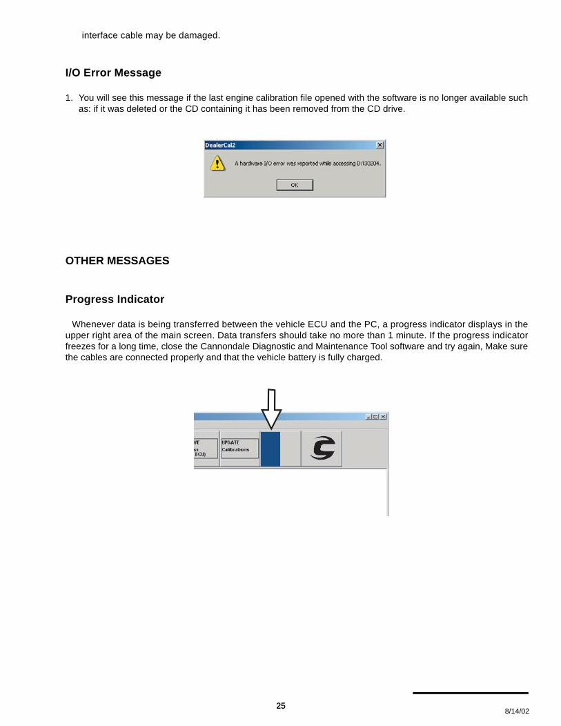
I/O Error Message
1. You will see this message if the last engine calibration file opened with the software is no longer available suchas: if it was deleted or the CD containing it has been removed from the CD drive.
OTHER MESSAGES
Progress Indicator
Whenever data is being transferred between the vehicle ECU and the PC, a progress indicator displays in theupper right area of the main screen. Data transfers should take no more than 1 minute. If the progress indicatorfreezes for a long time, close the Cannondale Diagnostic and Maintenance Tool software and try again, Make surethe cables are connected properly and that the vehicle battery is fully charged.
25 8/14/02
25

Retrying Checksum
Data is transferred between the vehicle and PC in small “packets” or chunks. During the transfer process, checksare performed by the diagnostic tool (software) to ensure that the data is not damaged during the transfer. Eachsmall packet is checked during the transfer. If data errors are detected in the packet, the message “RetryingChecksum...” will display in the progress indicator:
Typically, this is due to electrical “noise” or other interference during the process. The diagnostic tool will keeptrying automatically.
© 2002 Cannondale Corporation - All Rights Reserved26
Electrical_EFI Service Manual.fm

COMMUNICATION CABLE
Connecting the communication cable
Motorcycles and ATVs have a “diagnostic” con-nector integrated into the main wiring harness. Thecommunication cable connects the PC to the vehicleusing the connector.
CAUTION :
Connect the communication cable with thevehicle engine management system OFF.
On 2001 and 2002 Motorcycle models, the diag-nostic connector is located near the ignition coil atthe top of the cylinder head. Vehicle componentsmust be removed to access the connector.
On 2003 Motorcycles, the diagnostic connector islocated near the main fuse under the seat.
On 2001 - 2003 ATV, the diagnostic connector islocated near the radiator shroud under the frontfender on the left side of the ATV.
NOTE :Check the diagnostic connector pins for anybending or damage before connecting to thevehicle.
1. Serial connector (PC)2. LED3. Cable4. Connector (vehicle)
1
3
4
2
27 8/14/02
27
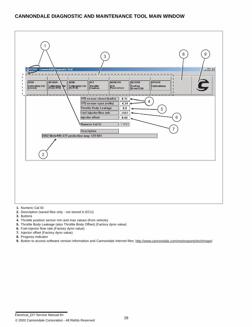
CANNONDALE DIAGNOSTIC AND MAINTENANCE TOOL MAIN WINDOW
1. Numeric Cal ID2. Description (saved files only - not stored in ECU)3. Buttons4. Throttle position sensor min and max values (from vehicle)5. Throttle Body Leakage (also Throttle Body Offset) (Factory dyno value)6. Fuel injector flow rate (Factory dyno value)7. Injector offset (Factory dyno value)8. Progress indicator9. Button to access software version information and Cannondale internet files: http://www.cannondale.com/motorsports/tech/maps/
38 9
4
6
5
2
1
7
© 2002 Cannondale Corporation - All Rights Reserved28
Electrical_EFI Service Manual.fm

Engine Calibration File (“Map”) Identification
All Cannondale factory authorized engine cali-bration files are identified by a Numeric Cal ID code.
The Numeric Cal ID number defines the year,model, and issue sequence of any specific enginecalibration file. The engine calibration Numeric Cal IDnumber is displayed in the top left corner of the Can-nondale Diagnostic and Maintenance Tool main
window whenever a “map” is opened or receivedfrom the vehicle ECU. The code number also dis-plays at the Numeric Cal ID field within the mainwindow.
Cannondale vehicles (ATVs and motorcycles) areloaded at the factory with a model specific authorizedengine calibration file. This file can also be referredto as the vehicle “map.”
Engine calibration files have the filename extension“.ccf”
A database of Cannondale authorized engine cali-bration calibrations files is maintained on the Can-nondale website so that service technicians haveready access to the correct factory authorized cali-bration files for a particular vehicle VIN.
Go to http://www.cannondale.com/motorsports/tech/maps/.
If “Untitled” is displayed in the top left corner of themain window, no calibration file has been opened(from a saved file) or received from the vehicle ECU.
ECU OPERATING CODE
The ECU operating code is installed at the factorybefore the engine calibration file is loaded.
The operating code also known as the “HEX” file islike Windows 98 or XP, an “operating system” used inmany PCs. An engine calibration file can be thoughtof as a program like Microsoft Excel or NetscapeNavigator, programs which run under Windows.
NOTE :When a calibration file for a model is updated the SEQ number increases. However, due to continual productevolution, the updated calibration file for the model may not be authorized for use in vehicles producedpreviously. Always consult the Cannondale website for the compatibility of calibration files for a specificvehicle VIN number.
30202.ccf
YEARReset every 10 years
(ex. 2002)
SEQUENCE NUMBERAssigned sequentially.
New files are
assigned the next available
number 00-99 for the model.
Always check the website
to verify that a calibration
file is authorized for use
in a particular model.
MODEL CODE
00 - X440s
01 - X440
02 - C440
03 - E440
30 - Cannibal
31 - Speed
32 - Blaze 440
33 - Moto 440
Filename extensionAll Cannondale authorized
engine calibration files will
have the filename extension
".ccf."
29 8/14/02
29

ATV and Motorcycle operating codes are NOTinterchangeable.
The software tool can load operating code versionupdates to the ECU.
The software does not read back the installed oper-ating code currently in the ECU.
To install (update) an operating code
CAUTION :
When an operating code is loaded into an ECUusing the software tool, ALL information iserased from the ECU memory including theengine calibration file and vehicle variables(throttle body leakage, fuel injector flow rate,injector offset). The engine calibration file andvehicle variables must be reinstalled into theECU following the operating code update.
Receive the installed engine calibration fileFIRST. As long as nothing goes wrong with thePC and the information is retained by thesoftware tool, the information can be sent to theECU right after the operating code update isfinished.
WRITE down the engine calibration file IDnumber (Numeric Cal ID), the throttle bodyleakage, fuel injector flow rate, and injectoroffset before continuing.
1. On ATVs turn the ignition switch ON.
On Motorcycles, disconnect the starter solenoidso that the engine will not turn over when the startbutton is held down in a later step.
2. In the main window click File - Code Download.
© 2002 Cannondale Corporation - All Rights Reserved30
Electrical_EFI Service Manual.fm

3. In the ECU Reprogramming Tool window, selectthe operating code file to send.
Have an assistant press and continue to hold thestart button.
Click Download.
The progress indicator will display while the trans-fer take place.
When the transfer is complete release the startbutton. Click Close.
4. Reinstall the correct engine calibration file. Besure to update the vehicle variables before send-ing the file to the ECU.
5. On Motorcycles, be sure to reconnect the startersolenoid.
31 8/14/02
31

Opening a SAVED Calibration file
NOTE :A saved calibration file might be one that you havereceived via e-mail, downloaded from the ourwebsite, or one that is stored on a diskette or CD.This button functions the same way as if you clickFile - Open in the top right corner of the mainwindow.
Once “opened,” the file is ready for installationinto the vehicle ECU.
CAUTION :
Before the saved file is sent to the ECU, be sureto receive the vehicle variable or they will belost. Refer to "Receiving a calibration fileFROM THE ECU “Reading a map andvariables”" starting on page 33.
To open a saved calibration file,
NOTE :In version 2.0 of the software, when the programis launched, the last engine calibration file thatwas opened is automatically open in the mainwindow. This feature is useful for servicing manyunit at once, however, be sure to check the enginecalibration file Numeric Cal ID code in the mainwindow to make sure that the right file is beingused. If not, complete steps 2 -3.
1. In the main window, click on the “OPENCalibration File (saved) button.
Use the Windows explorer to locate (browse for)the saved engine calibration file.
Select the file and click OK.
2. The file is now “loaded” to the main window.
CAUTION :
Check the Numeric Cal ID field in the mainwindow to make sure the filename selected isdisplayed. If not, go back to step 2 and repeat.
© 2002 Cannondale Corporation - All Rights Reserved32
Electrical_EFI Service Manual.fm

Receiving a calibration file FROM THE ECU“Reading a map and variables”
By receiving the engine calibration file or thevehicle variables from the ECU, the technical candetermine which specific engine calibration file is inuse by the vehicle and what the vehicle specificvariable are included in the data file: throttle min/max, Throttle body leakage (also known as offset,fuel injector flow rate, and injector offset).
NOTE :When you “receive” an engine calibration file, acopy of the file stored in the vehicle ECU is loadedin the software tool main window. The vehiclespecific variables or “calibration” are also loaded.No information is removed or deleted from thevehicle ECU.
You can select to receive all the calibration filefrom the vehicle ECU or just the throttle body andinjector variables or “calibrations.”
In case of PC failure, it is a good idea, whenever afile is received from the vehicle ECU to write downthe throttle body and injector variables or“calibrations.”
To receive
1. Connect the interface cable to the PC andvehicle.
2. Open the Cannondale Diagnostic Tool softwareon your PC.
3. Power-up the ECU.
4. Click the RECEIVE Calibration File (from ECU)button.
After you click the button, the data transfer willstart. While the data is copied from the ECU to thePC the progress indicator in the upper right of themenu will display and the LED on the interfacecable block may appear to flicker. The timerequired for the transfer could vary. It should takeplace within 1 minute. When the entire data trans-fer process is complete, you will see the “Receive
complete” message.
5. Click OK. The vehicle calibration file has now beencopied to the Cannondale Diagnostic Toolprogram. 4-SEND Calibration File (to ECU).
33 8/14/02
33

Sending a calibration file or “map” to the ECU - “Changing a map”
NOTE :“Sending” a calibration file transfers the enginecalibration file and vehicle variables currentlyopen in the Cannondale Diagnostic andMaintenance Tool main window to the vehicleECU.
Sending will over-write the ECU current enginecalibration file and vehicle variables.
Vehicle variables (throttle min/max, throttle bodyleakage (a.k.a Throttle body leakage), fuel injectorflow rate, and injector offset) are over-written onlyif the values have been entered through theUpdate Calibrations button. If no values areentered, the vehicle variables stored in the ECUare used.
If the interface cable is disconnected accidentallyor problems with the PC interrupt the transferprocess, the engine calibration file send processshould be start over from the beginning. Although,it is possible to quickly reconnect the interfacecable during the transfer process, information canbe lost or damaged.
Do not experiment with calibration files!Sending unidentified, altered, or third partycalibration files can result in severe damage tothe vehicle or affect the safe operation of thevehicle. You could be severely injured or killedin a resulting accident.
Always consult the Cannondale website(www.cannondale.com) for calibration filesauthorized for a specific vehicle identificationnumber (VIN).
1. To send a calibration file to the vehicle ECU, startby connecting the interface cable to the computerand vehicle.
2. Open the Cannondale Diagnostic and Mainte-nance Tool software on your PC. The CDMT pro-gram will automatically open the last enginecalibration file that was open using the program.
You’ll want to pay close attention to what enginecalibration file is actually open before you sendthe file to the ECU in the following steps.
Click the OPEN Calibration File (saved) buttonto open the Open Calibration File window tobrowse for a saved engine calibration file on yourPC. Select the filename and click OPEN.
-- or --
Select File-> Open.
You should now have an engine calibration file“open” in the CDMT main window. Confirm thatthe correct engine calibration file name is dis-played in the top left corner of the CDMT windowand at the Numeric Cal ID field.
3. Next, make sure the vehicle engine managementsystem is powered-up. When the vehicle is pow-ered-up, the LED on the interface cable blockshould be lit.
4. Click the SEND Calibration File (to ECU) button.
If the calibration file open in the main window dif-fers from the one currently stored in the ECU, the“Cal version different. Do you wish to proceed?”prompt will display. Click yes to send the file. Clickcancel to exit.
If you click YES, the file that is open in the mainwindow will be sent to the vehicle ECU. It willover-write the current calibration file stored in theECU. During this process, the vehicle variablescurrently stored in the ECU will be retained if thevalues have not been entered first using theUpdate Calibrations button. If values had beenentered, they will over-write the ECU values dur-ing the send process. When the send has beencompleted the vehicle ECU will automaticallypower itself down. The LED on the interface cableblock will turn off indicating the ECU power is nowoff. The calibration file just sent will remain “open”in the CDMT window until the program is exited oranother calibration file is opened or received.
Setting the throttle position sensor minimum and maximum values
The minimum and maximum values are capturedand recorded into the ECU using the SET ThrottlePosition button.
© 2002 Cannondale Corporation - All Rights Reserved34
Electrical_EFI Service Manual.fm

The thro t t le pos i t ion sensor min imum andmaximum values must be set using the CDMTanytime the throttle body is serviced (removed,replaced, installed). It also must be set if the ECUoperating code is updated. Set the throttle positionwith the engine off. When the values are set usingthe tool, the minimum and maximum value actuallyread into the software by the technician are checkedagainst a range. If any read value is out of range, thesoftware will report it.
NOTE :The “TPS Sensor Closed (volts)” and the “TPSSensor open (volts)” are displayed in the CDMTmain screen anytime a engine calibration file isopen or received from the ECU.
1. To set the throttle position, start by making surethat the idle adjustment screw is backed offcompletely. The throttle plate should becompletely shut before you continue.
Double check the throttle bellcrank after backingthe idle adjustment screw off; any slight tension inthe throttle cable can hold the plate open. Confirmthat it is closed all the way by rotating the throttlebellcrank with your hand - closing it firmly.
NOTE :When shutting the throttle body plate to set theminimum value, avoid backing the adjustmentscrew out too far that it falls out of the stop plate.
2. Make sure the interface cable is connected tothe computer and vehicle securely.
3. Open the Cannondale Diagnostic andMaintenance Tool software on your PC.
4. Power-up the vehicle engine managementsystem.
5. An engine calibration file must be open in theCDMT main window to continue. Use the OPENCalibration File (saved) or use the RECEIVECalibration File (from ECU) button to receive thecalibration file that is currently stored in the vehi-cle ECU.
6. Click the SET Throttle Position button. The Cali-brate Throttle window will display. When the win-dow displays the closed voltage (minimum) andopen voltage (maximum) numeric values shown
are the values of the current engine calibrationfile.
Again, make sure the throttle plate is completelyclosed and click the Read Closed Voltage button.You should see a change in the numeric value tothe right of the button. The change is the mini-mum voltage value read from the vehicle TPSsensor when completely closed. The value canapproach zero, but should be within the typicalrange indicated in the window.
Next, have an assistant hold the throttle lever fullyopen. While the lever is held in the “wide openthrottle” position, click the Read WOT Voltagebutton. You should see a change in the numericvalue to the right of the button. Tell your assistantto release the throttle lever.
Now, both values have been read from the vehicleTPS sensor. You have two options to consider; go
35 8/14/02
35

to the next step to learn more.
7. If you click the Accept Values button, the values ofthe engine calibration file currently stored in theCDMT will change to the new ones and immedi-ately the Send Calibrations to the ECU prompt willdisplay.
If you click Cancel, the new values you just readfrom the vehicle will be “forgotten” and the valueswill revert back to the values of the currently openengine calibration file; and, the CDMT main win-dow will display.
8. If you click OK, at the Send Calibrations to ECUprompt, the Select TPS/Inj Calibrations windowwill display next. Go to the next step.
If you click Cancel at the Send Calibrations toECU prompt, the new values will be updated inthe currently open engine calibration file andremain until the file is closed, another new enginecalibration file opened or the values are changed
again using the Set Throttle Position button.
9. At the Select TPS/Inj Calibrations window, selectthe values to send to the ECU by clicking in thecheck boxes. The values displayed in the “FromFile” column are the values of the current enginecalibration file open in the CDMT. The values ofthe “From ECU” column are the old values.
Click OK to send the values to the ECU. Watch
Click this buttoto read the TPsensor minimuvoltage. These fields
displays the valuesthat are "ready to accept"The fields initiallyshow a value of thecurrently open file.The values will changeimmediately after thebuttons at the left areclicked.
The Send Calibrations to the ECU prompt
© 2002 Cannondale Corporation - All Rights Reserved36
Electrical_EFI Service Manual.fm

the progress indicator. When the send is com-plete, the Send complete prompt will display, clickOK.Click Cancel and the “From File” values will notbe sent. They will remain in the currently openengine calibration file.
10. Power-up the vehicle ECU and click on theMONITOR ECU Parameters button to displaythe ECU Monitor window.
Find the “Throttle (%) Open value.” Makesure the ECU parameters display is in theContinuous mode.
Adjust the idle adjustment screw so that the“Throttle (%) Open” value increases by 3. Forexample, if the value was 2.3 with the throttleplate fully closed, turn the adjuster until thevalue reads 5.3. If you do not open the throttleplate the engine may not have enough air toidle. Opening the throttle plate 3% should beenough to achieve idle.
11. Start the engine and allow to idle normallyuntil the vehicle to reach operatingtemperature (70°C). Fine tune the idle settingas specified for the vehicle.
CALIBRATIONS
Updating throttle body and fuel injector calibrations
The Update Calibrations window enables you tocalibrate or “set” the vehicle specific variables whichare included in the engine calibration file data:Throttle body leakage (offset), fuel injector flow rate,and injector offset. These variables enable tuning theinstalled map to compensate for slight manufac-turing variations in each. The numeric values forthese variables are determined when the vehicle isdyno-tested the factory and loaded to the calibrationfile.
When a throttle body or fuel injectors are replaced -the calibration information are packaged with thenew parts so that service technicians can update thevehicle.
The calibration numeric values are part of the“map” file and displayed in the main window.
NOTE :When a new engine calibration file “map” is sent tothe ECU the software will prompt to change thevalues or use the current values stored in the oldmap.
• “Throttle Body Leakage” (also called ThrottleBody Offset)
(Input range 0 - 100)
The equivalent amount, in percent, of throttleopening required on a “perfect” throttle body tomatch the air flow of the vehicle's throttle body
The Select TPS/Inj Calibrations window
37 8/14/02
37

at the closed position. Typical values are from 0.0 to 1.0%
• “Injector Flow Rate”
(Input range 1500 - 3000)Typical values are from 2300-2800
The fuel injectors’ flow rate, used by the ECU to convert fuel mass in milligrams to injector pulse width inmilliseconds. The lower the flow rate, the longer the ECU has to hold the injector open to deliver a given fuelmass. For a set of injectors, using a lower flow rate setting will deliver more fuel (richer running), and using ahigher flow rate setting will deliver less fuel (leaner running).
• “Injector Offset”
(Input range 0.3 - 1.6)Typical values are from 0.5 to 1.5
The amount of “dead” time of the fuel injector. The fuel injector is an electro-mechanical device, and there isa delay from the time the electrical signal to open is delivered until the mechanical parts move and allow fuelto flow. This delay time is added to all pulse widths. In low fuel delivery situations, the injector offset can bethe majority of the pulse width, so the proper value is important to maintain the proper amount of fuel at lowthrottle openings. Using a higher injector offset will deliver more fuel (richer running), and using a lowerinjector offset will deliver less fuel (leaner running). To update calibrations, start by connecting the interface cable to the computer and vehicle.
To update calibrations
1. Click the “UPDATE Calibrations” button.
2. Click in the appropriate field in the window and type in the calibration (variable) values.
3. Click “OK” and the typed-in values will display in the CDMT main window. Now, you have to send these valuesto the ECU for them to take effect. Click the “SEND Calibration File (to ECU)” button.
© 2002 Cannondale Corporation - All Rights Reserved38
Electrical_EFI Service Manual.fm

ECU MONITOR
Monitor selected ECU parameters with the vehicleengine running or with the vehicle engine off and theECU powered-up. It can be operated in “Continuous”(live) or “Hold” (snap shot) mode. You can start andrun the vehicle engine with the ECU monitor active.
While the monitor window is displayed, constantcommunications between the ECU and PC areoccurring - the ECU will not power itself down after 2minutes. The moment you click CANCEL, the twominute power-down timing will start if no other com-munication is attempted.
CAUTION :
When setting idle speed with the monitor, theengine must be at operating temperature 70°C.
Using the ECU Monitor
To use the monitor, start by connecting the interfacecable to the computer and vehicle.
1. Open the Cannondale Diagnostic Tool softwareon your PC.
2. Power-up the vehicle ECU.
3. Click the MONITOR ECU Parameters button.The ECU monitor window will be displayed.
Select “Continuous” to view live data.
Select “Hold” to take a snap shot and hold the val-ues displayed.
Click CANCEL to exit and close the monitor.
ECU Parameters (defined)
• “RPM” - displays the engine rpm
• “Throttle Position (%)” - displays thepercentage that the throttle plate is open. Thisvalue may not be “0” when fully closed or 100%when fully open.
• “Battery Voltage” - displays battery/ systemvoltage.
• “Airbox Temperature (degC)” - air temperaturereading as measured by the airbox air pressuresensor.
• “Airbox Pressure (kPa)” - airbox pressurereading as measured by the ECU sensor.
• “Engine Temperature “(degC)” - enginetemperature reading as measured by thecoolant temperature sensor.
• “IACV Stepper Position” step position of theIdle Air Control Valve (IACV). The ECU movesor “steps” the valve between 0 - 255 dependingon the current engine and air temperature.
39 8/14/02
39

READING FAULT CODES
To read fault codes
When a fault is reported, consult the fault diagnostic tables in this manual. Refer to "Fault Troubleshooting"starting on page 42.
CAUTION :
Obtain the vehicle’s wiring diagram before attempting any testing.
NOTE :Most faults reported by the system can be corrected by examining the connector attached to the device or bytracing circuit for an open or short circuit condition between the ECU connectors and the device connector.
A MIL Lamp fault code (an accessory code) will display on units without ECU interface accessories. The MILfault does not indicate a problem with normal engine operations, just the accessories.
Once a fault has been cleared through corrective action, close and reopen the Fault Report window; The ECUdoes not store intermittent or one time faults. The Fault Report window will only display current faults available.
1. To read faults, make sure the communication cable is connected correctly.
2. Click the “RECEIVE Fault(s) (From ECU)” button in the main window.
The Fault Report window will display with a list of faults the ECU was encountering when the button wasclicked.
These are “live” faults not stored faults. The GP Control MC1000 ECU programming does not store faults inmemory, therefore the faults displayed in the window are the faults the ECU reports when the Fault Report but-
© 2002 Cannondale Corporation - All Rights Reserved40
Electrical_EFI Service Manual.fm

ton was pressed. The Fault Report window doesnot constantly update fault conditions.
The Fault Report window sample above wastaken while the Cannondale Diagnostic Tool wasconnected to an 2002 X440s motorcycle. Thisvehicle does not have a cooling fan. The “CoolingFan open fault” will report when the tool is con-nected to a motorcycle, however, it can be disre-garded. Also for the sample fault report above, wetemporarily disconnected the air temperature sen-sor - notice the “Air temp sensor high fault” thatwas reported.Connect the interface cable to the computer andvehicle.
Fault Report window
41 8/14/02
41

FAULT TROUBLESHOOTING
Consult the following troubleshooting tables whendiagnosing a fault reported by the Cannondale Diag-nostic and Maintenance Tool Fault Report windowfunction. Refer to "Reading Fault Codes" starting onpage 40.
SENSOR SUPPLY VOLTAGE
Fault Reported Possible Cause Action
Sensor power supply faultECU damaged
wiring faultDisconnect ECU and go to Test 1.
Pinpoint Tests
Test Result Action
1. Check wire and terminalintegrity: - P1 B3
OKDisconnect throttle position sensor, air
temperature sensor, and coolant sensor,and go to Test 2.
Faulty Correct and go to Test 4.
2. Check for harness shortcircuit- P1 B3 to P1 E4
OK Reconnect ECU and go to Test 3.
Short circuitLocate short in harness and correct and
go to Test 4.
3. With ignition ‘ON’ checkvoltage at:- P1 B3 at the back of the con-nector locate wire (70 White)or at CN3 pin B.
4.5 to 5.5v Go to Test 4.
Faulty Replace the ECU, go to Test 4.
4. Reconnect harness, runengine check for presence offault.
OK Done
Fault still present Contact Cannondale Dealer Service.
Circuit Diagram
© 2002 Cannondale Corporation - All Rights Reserved42
Electrical_EFI Service Manual.fm

SYSTEM VOLTAGE
Fault Reported Possible Cause Action
Battery voltage low fault Wiring/ Stator/ Regulator/
Battery
Check bat te ry vo l tage a t ba t te ry ;minimum voltage 12.8v.
Disconnect ECU and go to Test 1.
Battery voltage high fault RegulatorEnsure regulator output voltage is within
specified range.
Pinpoint Tests
Test Result Action
1. Check wire and terminalintegrity: - P2 E1
OK Go to Test 2.
Faulty Correct and go to Test 3.
2. With ignition ‘on,’ checkvoltage at:- P2 E1
Same as battery voltage Go to Test 3.
Less than battery voltage Locate and correct wiring fault; go to Test
3.
3 . Run eng ine check fo rpresence of fault.
OK Done
Fault still present Contact Cannondale Dealer Service.
Circuit Diagram
43 8/14/02
43

FUEL PUMP
Reported Fault Possible Cause Action
Fuel pump short Damaged fue l pump
(internal short circuit), harnessshort circuit, damaged ECU
Component test fuel pump. Refer to"Fuel Pump" starting on page 44.
Make sure fuel pump connector and fuelpump terminals are secure.
Verify good main fuse.
Disconnect ECU and go Test 1.
Fuel pump open
Damaged fue l pump(internal open circuit) harnessopen circuit, harness con-nector disconnected or ter-minals at pump loose or dis-connected, open circuit tobattery 12V(+).
Pinpoint Tests
Test Result Action
1. Check wire and terminalintegrity: - P1 H1
OK Disconnect the fuel pump and go to Test
2.
Faulty Locate and correct and go to Test 2.
2 .Check fo r shor t c i r cu i tbetween:- P1 H1 to ground
Open Go to Test 3.
Shorted Locate and correct wiring fault; go to Test
7.
3. Check continuity between:- P1 H1 and CN16 pin B
Continuity Go to Test 4.
OpenLocate and correct wiring fault; go to Test
5.
4. Reconnect ECU, presseng ine s tar t but ton , wa i t 5seconds and check for shortcircuit between:- CN16 B to ground
Open Go to Test 5.
Shorted Replace ECU, go to Test 7.
5. Verify 12V (+) at CN16 pin A
OK Go to Test 6.
NoneLocate and correct wiring fault; go to Test
6.
6. Reconnect the ECU andfuel pump. Verify that pump runsbriefly (3 seconds) when enginestart button is pressed.
OK Go to Test 7.
Faulty Replace ECU and go to Test 7.
7. Run engine and check forpresence of fault.
OK Done
Fault still present Contact Cannondale Dealer Service.
Circuit Diagram
© 2002 Cannondale Corporation - All Rights Reserved44
Electrical_EFI Service Manual.fm

IGNITION COIL
Fault Possible Cause Action
Coil short fault
Damaged ignition coil orECU, harness short circuit,coil connector disconnectedor damaged
Component test ignition coil. Refer to"Ignition Coil" starting on page 45.
Check ignition coil harness connector issecure.
Disconnect ECU and go to Test 1.
Pinpoint Tests
Test Result Action
1. Check wire and terminalintegrity:- P2 H1
OK Go to Test 2.
Faulty Locate and correct and go to Test?.
2. Check resistance value:
Disconnect diagnostic con-nector CN10, lighting connectorCN26 (Motorcycle only), removeEMS power relay. Measurebetween relay socket terminal30 and P2 H1.
0.6 Ohms Disconnect ignition coil and go to Test 3.
Open circuit Go to Test 4.
Short circuit Disconnect ignition coil and go to Test 5.
3. Check wire for short circuitbetween:- P2 H1 to ground
Short circuitLocate and correct wiring fault and go to
Test 7.
Open circuit Go to Test 7.
4 . Check w i re con t inu i tybetween:EMS power relay socket ter-minal 30 and CN8 pin 2.
Continuity Go to Test 6.
Open circuit Correct wiring fault and go to Test 7.
5. Check wiring for short circuitbetween:EMS power relay socket ter-minal 30 and P2 H1
Short circuitLocate and correct wiring fault and go to
Test 7.
Open circuit Go to Test 6.
6. Check ignition coil primaryresistance across coil pins 1 and2
0.6 Ohms primary Go to Test 7.
Faulty Replace coil, go to Test
7. Reconnect ECU, run enginecheck for presence of fault.
OK Done
Fault still present Contact Cannondale Dealer Service.
Circuit Diagram
45 8/14/02
45

COOLING FAN (ATV ONLY)
Fault Possible Cause Action
Cooling fan short fault,Cooling fan open fault
Damaged cool ing fan orECU, harness short circuit,fan connector disconnected ordamaged
Component test the cooling fan. Refer to"Cooling Fan (ATV Only)" starting onpage 46.
Component test the coolant sensor.Refer to "Coolant Sensor" starting onpage 53.
Check that cooling fan harness connectoris secure.
Verify good main fuse.
Disconnect ECU and go to Test 1.
Pinpoint Tests
Test Result Action
1. Check wire and terminalintegrity:- P2 G1, P2 G2
OK Disconnect cooling fan and go to Test 2.
FaultyLocate and correct wiring fault and go to
Test 5.
2. Check wire for short circuit:- P2 G1 to ground- P2 G2 to ground
OK Go to Test 3.
Short circuitLocate and correct wire fault and go to
Test 5.
3 . Check w i re con t inu i t ybetween:- P2 G1 and CN22 pin B
OK Go to Test 4.
Open circuit Correct wiring fault, go to Test 5.
4. Verify 12V(+) at CN22 pin A
OK Go to Test 5.
NoneLocate and correct wiring fault, go to Test
6.
5. Reconnect the cooling fanand ECU and verify proper fanoperation (on at 85°C, off at80°C coolant temperature).Verify correct airflow.
OK Done
Faulty Replace ECU and go to Test 7.
7. Run engine and check forpresence of fault.
OK Done
Fault still present Contact Cannondale Dealer Service.
Circuit Diagram
© 2002 Cannondale Corporation - All Rights Reserved46
Electrical_EFI Service Manual.fm

FUEL INJECTORS
Fault Possible Cause Action
Injector A short fault (left)
Injector B short fault (right)
Damaged injector or ECU,harness short circuit
- f looding indicates shortcircuit
Component test the injector. Refer to"Fuel Injectors" starting on page 19.
Check that injector harness connector issecure.
Disconnect ECU and go to Test 1. Injector A open fault (left)
Injector B open fault (right)
Damaged injector, injectorconnector disconnected ordamaged , harness opencircuit
- m isf i re indicates opencircuit
Pinpoint Tests
Test Result Action
1. Check wire and terminalintegrity:
- P1 H2
- P1 H3
OK Go to Test 2.
FaultyLocate and correct wiring fault and go to
Test 7.
2. Check resistance value:
MotorcycleDisconnect diagnostic connectorCN10, lighting connector CN26,remove EMS power r e lay.Measure between relay socketterminal 30 and:
- P1 H2 (Left injector)
- P1 H3 (Right injector)
ATVDisconnect the ignit ion coil,diagnostic connector CN10,switch engine stop button toOFF position. Measure betweenP2 E1and:
- P1 H2 (Left injector)
- P1 H3 (Right injector)
12.25 ± 0.50 Ohms at 20 ±2°C
Disconnect relevant injector and go toTest 3.
Open circuit Go to Test 4.
Short circuitDisconnect relevant injector and go to
Test 5.
47 8/14/02
47

3. Check wire for short circuit
- P1 H2 to ground
- P1 H3 to ground
OK Go to Test 7.
Short circuitLocate and correct wire fault and go to
Test 7.
4. Check wire continuity:
MotorcycleDisconnect diagnostic connectorCN10, lighting connector CN26,remove EMS power re lay.Measure between relay socketterminal 30 and:
- relevant injector pin 1
- P1 H3 to CN6 pin 2 (Rightinjector)
- P1 H2 to CN7 pin 2 (Leftinjector)
ATVDisconnect the ignit ion coil,diagnostic connector CN10,switch engine stop button toOFF position. Measure betweenP2 E1and:
- relevant injector pin 1
- P1 H3 to CN6 pin 2 (Rightinjector)
- P1 H2 to CN7 pin 2 (Leftinjector)
Continuity Go to Test 6.
Open circuitLocate and correct wire fault and go to
Test 7.
FUEL INJECTORS
© 2002 Cannondale Corporation - All Rights Reserved48
Electrical_EFI Service Manual.fm

5. Check short circuit:
MotorcycleDisconnect diagnostic connectorCN10, lighting connector CN26,remove EMS power r e lay.Measure between relay socketterminal 30 and:
- P1 H3
- P1 H2
ATVDisconnect the ignit ion coil,diagnostic connector CN10,switch engine stop button toOFF position. Measure betweenP2 E1and:
- P1 H3
- P1 H2
OK Go to Test 6.
Short circuitLocate and correct wiring fault proceed to
Test 7.
6. Check injector resistance:
- relevant injector across ter-minals 1 to 2
12.25 ± 0.50 Ohms at 20 ±2°C
Go to Test 7.
Faulty Replace injector go to Test 7.
7. Run engine and check forpresence of fault.
OK Done
Fault still present Contact Cannondale Dealer Service.
Circuit Diagram
FUEL INJECTORS
49 8/14/02
49

THROTTLE POSITION SENSOR (TPS)
Fault Possible Cause Action
Throttle position sensor highfault
Throttle position sensor lowfault
Damaged TPS sensor,ECU, harness short or opencircuit, TPS sensor connectordisconnected or damaged
Component test the TPS sensor.
Check that sensor harness connector issecure.
Disconnect ECU and go to Test 1.
Pinpoint Tests
Test Result Action
1. Check wire and terminalintegrity:
- P1 B3
- P1 E3
- P1 B4
OK Disconnect TPS sensor and go to Test 2.
FaultyLocate and correct wiring fault and go to
Test 5.
2 . Check fo r shor t c i r cu i tbetween:
- P1 E3 to ground
OK Go to Test 3.
Short circuitLocate and correct wiring fault and go to
Test 5.
3. Check cable continuity:
- P1 E4 to CN3 pin A
- P1 E3 to CN3 pin C
- P1 B3 to CN3 pin B
OK Go to Test 4.
Open circuitLocate and correct wiring fault and go to
Test 5.
4. Check cable for short circuit:
- P1 E3 to P1 B3
- P1 E3 to P1 E4
OKReplace throttle position sensor, go to
Test 5.
Short circuitLocate and correct wiring fault and go to
Test 5.
5. Reconnect harness, runengine and check for presenceof fault.
OK Done
Fault still present Contact Cannondale Dealer Service.
Circuit Diagram
© 2002 Cannondale Corporation - All Rights Reserved50
Electrical_EFI Service Manual.fm

AIR TEMPERATURE SENSOR
Fault Possible Cause Action
Air temp sensor high fault
Air temp sensor low fault
Damaged air temperaturesensor, ECU, harness short oropen c i rcu i t , sensor con-nec to r d i sconnec ted o rdamaged
Component test the air temperaturesensor.
Check that sensor harness connector issecure.
Disconnect ECU and go to Test 1.
Pinpoint Tests
Test Result Action
1. Check wire and terminalintegrity:
- P1 D1
- P1 E4
OK Disconnect TPS sensor and go to Test 2.
FaultyLocate and correct wiring fault and go to
Test 7.
2. Check resistance value:
- P1 D1 to P1 E4
(verify value at temperaturetested; see table)
OKDisconnect temperature sensor and go to
Test 6.
Open circuit Go to Test 3.
Short circuitDisconnect temperature sensor and go to
Test 4.
3. Check wire continuity:
- P1 D1 to CN5 pin 2
- P1 E4 to CN5 pin 1
OK Go to Test 5.
Open circuitLocate and correct wiring fault and go to
Test 7.
4. Check for wire short circuit:
- P1 D1 to P1 E4
OK Go to Test 5.
Short circuitLocate and correct wiring fault and go to
Test 7.
5. Check sensor resistance:
- CN5 pin 1 to pin 2
(verify value at temperaturetested; see table)
OK Go to Test 7.
Faulty Replace sensor, go to Test 7.
6. Check wire for short circuit”
- P1 D1 to ground
OK Go to Test 7.
Short circuitLocate and correct wiring fault and go to
Test 7.
7. Reconnect harness, runengine and check for presenceof fault.
OK Done
Fault still present Contact Cannondale Dealer Service.
51 8/14/02
51

Circuit Diagram
Air Temperature Sensor Resistance RangeResistance(ohms)
Temp. (deg. C)
Temp.(deg. F)
Resistance(ohms)
Temp. (deg. C)
Temp. (deg. F)
Resistance(ohms)
Temp.(deg. C)
Temp. (deg. F)
15071 -20 -4 1700 30 86 331 80 17611739 -15 5 1414 35 95 287 85 1859215 -10 14 1181 40 104 250 90 1947290 -5 23 992 45 113 219 95 2035808 0 32 837 50 122 192 100 2124659 5 41 710 55 131 169 105 2213763 10 50 604 60 140 149 110 2303058 15 59 517 65 149 132 115 2392500 20 68 444 70 158 118 120 2482056 25 77 382 75 167 N/A N/A N/A
AIR TEMPERATURE SENSOR
© 2002 Cannondale Corporation - All Rights Reserved52
Electrical_EFI Service Manual.fm

COOLANT SENSOR
Fault Reported Possible Cause Action
Engine temp sensor high fault
Engine temp sensor hi fault
Damaged coolant temper-ature sensor, ECU, harnessshort or open circuit, sensorconnector disconnected ordamaged
Component test the coolant temperaturesensor. Refer to "Coolant Sensor" startingon page 53.
Check that sensor harness connector issecure.
Disconnect ECU and go to Test 1.
Pinpoint Tests
Test Result Action
1. Check wire and terminalintegrity:- P1 B2- P1 E4
OK Go to Test 2.
FaultyLocate and correct wiring fault and go to
Test 7.
2. Check resistance value:- P1 B2 to P1 E4 (veri fy value at temperaturetested; see table)
OKDisconnect temperature sensor and go to
Test 6.
Open circuit Go to Test 3.
Short circuitDisconnect temperature sensor and go to
Test 4.
3. Check wire continuity:- P1 B2 to CN4 pin 2- P1 E4 to CN4 pin 1
OK Go to Test 5.
Open circuitLocate and correct wiring fault and go to
Test 7.
4. Check for wire short circuit:- P1 B2 to P1 E4
OK Go to Test 5.
Short circuitLocate and correct wiring fault and go to
Test 7.
5. Check sensor resistance:- CN4 pin 1 to pin 2(veri fy value at temperaturetested; see table)
OK Go to Test 7.
Faulty Replace sensor, go to Test 7.
6. Check wire for short circuit”- P1 B2 to ground
OK Go to Test 7.
Short circuitLocate and correct wiring fault and go to
Test 7.
7. Reconnect harness, runengine and check for presenceof fault.
OK Done
Fault still present Contact Cannondale Dealer Service.
Circuit Diagram
53 8/14/02
53

Coolant Sensor Resistance RangeResistance(ohms)
Temp. (deg. C)
Temp.(deg. F)
Resistance(ohms)
Temp. (deg. C)
Temp. (deg. F)
Resistance(ohms)
Temp.(deg. C)
Temp. (deg. F)
45313 -40 -40 2500 20 68 322 80 17634281 -35 -31 2057 25 77 280 85 18526114 -30 -22 1707 30 86 243 90 19420003 -25 -13 1412 35 95 213 95 20315462 -20 -4 1175 40 104 187 100 21212002 -15 5 988 45 113 164 105 2219397 -10 14 834 50 122 144 110 2307415 -5 23 703 55 131 127 115 2395896 0 32 595 60 140 113 120 2484712 5 41 508 65 149 100 125 2573792 10 50 436 70 158 89 130 2663069 15 59 374 75 167 N/A N/A N/A
© 2002 Cannondale Corporation - All Rights Reserved54
Electrical_EFI Service Manual.fm

IDLE AIR CONTROL VALVE (IACV)
Fault Reported Possible Cause Action
Stepper motor fault
Damaged idle air controlvalve, ECU, harness short oropen circuit, IACV connectordisconnected or damaged
Component test the IACV. Refer to "IdleAir Control Valve (IACV)" starting onpage 55.
Check that harness connector is secure.
Disconnect ECU and go to Test 1.
Pinpoint Tests
Test Result Action
1. Check wire and terminalintegrity:- P1 E1- P1 E2- P1 F1- P1 F2
OK Go to Test 2.
FaultyLocate and correct wiring fault and go to
Test 5.
2. Check resistance:- P1 E1 to P1 F1- P1 E2 to P1 F2
53 ± 10% Ohms Disconnect the IAVC and go to Test 3.
Open circuit Go to Test 4.
Short circuit Disconnect IACV and go to Test 5.
3. Check cable for short circuit:- P1 E1 to ground- P1 E2 to ground- P1 F1 to ground- P1 F2 to ground
OK Go to Test 7.
Short circuitLocate and correct wiring fault and go to
Test 7.
4. Check cable continuity:- P1 E1 to CN25 pin A- P1 E2 to CN25 pin B- P1 F1 to CN25 pin C- P1 F2 to CN25 pin D
OK Go to Test 6.
Open circuitLocate and correct wiring fault and go to
Test 7.
5. Check cable for short circuit:- P1 E1 to P1 F1- P1 E2 to P1 F2
OK Go to Test 6.
Short circuitLocate and correct wiring fault and go to
Test 7.
Check IACV resistance:- IACV pin A to pin D- IACV pin B to pin C
53 ± 10% Go to Test 7.
Faulty Replace IACV, go to Test 7.
7. Reconnect harness, runengine and check for presenceof fault.
OK Done
Fault still present Contact Cannondale Dealer Service.
Circuit Diagram
55 8/14/02
55

CRANKSHAFT POSITION SENSOR
Fault Reported Possible Cause Action
Crank tooth sync fault
Damaged or contaminatedcrankshaft position sensor,damaged ECU, harness shortor open circuit, IACV con-nec tor d i sconnec ted o rdamaged
Check that harness connector is secure.
Check sensor air gap: 0.5 to 1.0 mm
Check for damaged flywheel teeth.
Check flywheel runout or play.
Disconnect ECU and go to Test 1.
Pinpoint Tests
Test Result Action
1. Check wire and terminalintegrity:- P1 A1- P1 B1
OK Disconnect sensor and go to Test 2.
FaultyLocate and correct wiring fault and go to
Test 8.
2. Check cable for short circuit:- P1 A1 to ground- P1 B1 to ground
OK Go to Test 3.
Short circuitLocate and correct wiring fault and go to
Test 8.
3. Check cable continuity:- P1 A1 to CN2 pin 2- P1 B1 to CN2 pin 1
OK Go to Test 4.
Open circuitLocate and correct wiring fault and go to
Test 8.
4. Check cable for short circuit:- P1 E1 to P1 F1- P1 E2 to P1 F2
OK Go to Test 6.
Short circuitLocate and correct wiring fault and go to
Test 8.
5. Check cable continuity:- Sensor cable screen to (frame)ground
OK Go to Test 7.
Open circuitLocate and correct wiring fault and go to
Test 8.
6. Check sensor resistance:Sensor pin 1 to pin 2
532 to 588 Ohms Go to Test 5.
Faulty Replace sensor and go to Test 8.
7. Check crank toothed wheel- Damaged teeth- Magnetic debris contamination
OK Go to Test 8.
FaultyClean / replace toothed wheel, go to Test
8.
8. Reconnect harness, runengine and check for presenceof fault.
OK Done
Fault still present Contact Cannondale Dealer Service.
© 2002 Cannondale Corporation - All Rights Reserved56
Electrical_EFI Service Manual.fm

COMPONENT TESTING (NON-EFI)
BATTERY
1. Filling electrolyte properly, Charging (times andrates).
2. Load testing using a commercially available loadtester.
3. Installation
Washers?LoctiteTorque
RECTIFIER /REGULATOR
NOTE :If vehicle is equipped with single phase rectifier/regulator, complete the steps described, but omitthe references made to the third wire (three phaserectifier/regulator).
Dynamic Test
1. Set multi-meter to DCV or Vdc (DC volts); switchthe range to 20 or 50V. Connect the multi meterleads to the battery terminals. Start and rev theengine up to 3000 r/min. Check the batteryvoltage.
If the voltage is higher than 13.5V, rev the engineto 5000 r/min. Check the reading on the meter, if itis lower than 14.8V, the charging system is OK.
If the voltage at 3000 r/min. is lower than 13.5V,go to the static test.
Static Test
1. Disconnect the rectifier/regulator from the vehiclewiring harness.
2. Switch the multi meter to Ohms (lowest range).
3. If the rectifier regulator has two red output wiresand two black output wires:
Test for continuity between both black wires; thereshould be continuity.
Test for continuity between both red wires; thereshould be continuity.
Test for short circuit between one of the red wiresand the two blacks; there should be no continuity.Repeat the test for the other red wire. Thereshould be no continuity.
4. Test for continuity between both black outputwires and the rectifier/regulator housing. Thereshould be no continuity.
5. Connect the positive multi meter probe to the redoutput wire of the rectifier/regulator. Connect theblack multi meter to the yellow input wire. Repeatthis procedure for each wire.
If an OL (no continuity) is indicated in all three yel-low wires, go to the next step.
If you have continuity on any of the three yellowwires, replace the rectifier/regulator with a newone.
6. Connect the negative multi meter probe to the redoutput wire of the rectifier/regulator. Connect thepositive probe to a yellow input wire. Check thereading. Repeat the test for each wire.
If a reading around 1 to 1.5 Ohms is obtained onall wires, go to the next step.
If an OL (no continuity) is obtained on any wire,replace the rectifier/regulator with a new one.
7. Connect the negative multi meter probe to thenegative output wire of the rectifier/regulator.Connect the positive multi meter probe to one yel-low wire. Check the reading. Repeat for all yellowwires.
If an OL (no continuity) is on all three wires isobtained, go to the next step.
If you have continuity on any wire, replace therectifier/regulator with a new one.
8. Connect the positive multi meter probe to the neg-ative output wire of the rectifier/regulator. Connectthe negative multi meter probe to one yellow wireand check the reading. Repeat for the other twoyellow wires.
If a reading around 1 to 1.5 Ohms is obtained onall three tests, the rectifier/regulator is OK.
57 8/14/02
57

If an OL (no continuity) is obtained on any one ofthe three tests, replace the rectifier/regulator.
Stator
NOTE :If vehicle is equipped with a single phase stator,complete the steps described, but omit thereferences made to the third wire (three phasestator).
Static Test
1. Disconnect the stator connector.
2. Set multi meter to the lowest Ohms setting.Measure the resistance between all three wirescoming from the stator. Start with one wire andread resistance between it and the other two.Repeat for remaining two wires.
If all readings are within 0.5 to 2.0 Ohms, go tothe next step.
If one of the readings is lower than 0.5 Ohms orhigher than 2.0 Ohms, replace the stator.
Connect one of the multi meter leads up to one ofthe three yellow wires. Connect the other multimeter lead up to the crankcase or to a groundingpoint on stator core if it has been removed. Checkthe reading on the meter. Make sure the connec-tion of the lead to the crankcase or stator core is agood one.
No reading or “OL” displayed, go to the next step.
If you have any reading between 100 Ohms andzero Ohms, replace the stator.
Dynamic Test - AC Output
1. Switch the multi meter to the AC voltage (range atleast 100 VAC). Make sure you do not switch toDCV or Vdc by mistake. Connect the multi meterleads between two of the yellow wires emergingfrom the stator. Start the engine and bring to 5000r/min. Check the reading on the meter. Switch oneof the multi meter leads to another yellow wireand check the reading again.
If three equal readings are obtained, all higherthan 50 VAC, the stator is ok. A problem may
exist in the rectifier/regulator. Test the rectifier/regulator.
FLYWHEEL
Inspection Points
1. Check for contact between the installed flywheeland crankshaft position sensor. Make sure thespecified sensor air gap is maintained throughoutflywheel rotation.
SERVICE:
1. Inspect the flywheel for cracking, damagedmagnetic material, key groove, and woodruff(crankshaft) key.
2. Check flywheel key location. Make sure the hubhas not spun in the aluminum body. The key “cut”in the hub should be aligned with the “C” in themolded “Cannondale” text.
START BUTTON (ATV & MOTORCYCLE)
1. Disconnect the engine start button from the mainharness.
2. Test for continuity between the two leads. Thereshould be no continuity.
3. Press and hold the button and test for continuity.There should be continuity when the button ispressed.
ENGINE STOP BUTTON
1. Disconnect the engine stop button from the mainharness.
2. Test for continuity between the two leads. Thereshould be continuity.
3. Press and hold the button and test for continuity.There should be no continuity when the button ispressed.
© 2002 Cannondale Corporation - All Rights Reserved58
Electrical_EFI Service Manual.fm

ENGINE STOP SWITCH (ATV)
1. Disconnect the engine stop switch from the mainharness.
2. Slide the switch to the RUN position. Thereshould be continuity between the two switchleads.
3. Slide the switch to the OFF position. There shouldbe no continuity.
CLUTCH LEVER SWITCH (ATV)
1. Disconnect the clutch switch connector from theswitch body.
2. Test for continuity between the switch terminals.There should be no continuity.
3. Pull in the clutch lever and test for continuitybetween the switch terminals. There should becontinuity.
KEY SWITCH
1. Disconnect the key switch connectors from themain harness.
2. Rotate the key to the OFF position.
Set the multi meter to Ohms. Test for continuitybetween any of the switch leads. There should beno continuity between any of the leads.
3. Rotate the key to the ON position. There shouldbe continuity between the green and violet leads.There should be no continuity between the yellowlead and the green or violet.
Rotate the switch to the “ON w/ Lights” position.There should be continuity between all leads.
STARTER SOLENOID
Dynamic Test - Solenoid Function
1. Press the engine start button. On ATVs, theadditional step of turning the ignition key ON andpulling in the clutch lever is required beforepressing the start button.
The solenoid is normal if the solenoid clicks whenthe start button is pressed.
If you do not hear a “CLICK”, go to the next test.
Static Test - Harness Voltage
1. Disconnect the solenoid from the main wiringharness.
2. On ATVs, turn the ignition key ON and pull in theclutch lever.
Set multi meter to DCV 20V range and connectthe positive meter lead to connector pin A; con-nect the negative meter lead to connector pin B.Press the engine start button. The reading shouldbe same as battery voltage (12.5 to 13.0Vdc).
If no voltage is detected, check the main fuse.
If the main fuse is OK, check the starting circuitfor an open or short circuit. Take corrective action.Consult the vehicle wiring diagram.
3. Set multi meter to Ohms. Connect the positivemeter lead to solenoid connector harness pin Band the negative meter lead to ground. Thereshould be continuity.
If an open circuit is detected, consult the vehiclewiring diagram.
Static Test - Resistance
1. Disconnect the solenoid from the main wiringharness.
2. Measure the resistance of the solenoid coil at theharness connector.
SERVICE: Solenoid coil resistance5.0 Ohm
OFF
RUN
RUN W/LTS
GREEN VIOLET YELLOW
59 8/14/02
59

Operation Test
1. Disconnect the solenoid from the main wiringharness.
2. Connect the positive lead of a 12V battery powersource to the solenoid coil positive lead or termi-nal (pin A) and the negative lead of the 12V bat-tery power source to the solenoid coil negativelead or terminal (pin B).
There should be continuity between the large ter-minals while the battery source is connected, andno continuity when the battery source is discon-nected.
STARTER MOTOR
Press the engine start button. On ATVs, the addi-tional step of turning the ignition key ON and pullingin the clutch lever is required before pressing thestart button.
The starter motor is normal if the engine turns overwhen the start button is pressed.
If the engine does not turn over:
- Check for loose battery cables or open circuit inbattery cables.- Check for loose solenoid terminals or connectors- Test the solenoid operation
3. Disconnect the positive cable from the positivestarter terminal. Press the engine start button. OnATVs, the additional step of turning the ignitionkey ON and pulling in the clutch lever is requiredbefore pressing the start button. Test for 12V (+)voltage between the starter cable and ground.There should be 12V (+) when the button ispressed.
If no voltage is found and the solenoid is OK,check the vehicle wiring harness starting circuitsfor short or open circuits. Consult the vehicle wir-ing diagram.
If voltage is present, go to next step.
4. Connect the starter motor positive terminaldirectly to the vehicle battery positive terminalwith a heavy lead similar in size to starter motorharness cable.
If the starter motor turns, check the vehicle wiring
harness starting circuits for short or open circuits.Consult the vehicle wiring diagram.
If the starter motor does not turn, confirm that theengine can be turned over manually. If the enginedoes not turn over manually, there is a internalengine problem. Take corrective action.
If the engine turns over manually, the starter isdamaged; replace it.
FUSES
When a fuse blows repeatedly, it usually indicates ashort circuit or current overload in the electricalsystem. The problem could be intermittent or con-stant.
1. To inspect the fuse, remove the fuse from theholder and inspect it.
WARNING
Use only specified fuse rating. An electri-cal fire or vehicle damaged can result if afuse rating other than specified is used.Using other materials in place of the fusewill cause damage to system.
REPLACE(1)
© 2002 Cannondale Corporation - All Rights Reserved60
Electrical_EFI Service Manual.fm

1 Printed : 8/14/02
15002066
INTRODUCTION - - - - - - - - - - - - - - - - - - - - - - 3Important Notice - - - - - - - - - - - - - - - - - - 3About the manual - - - - - - - - - - - - - - - - - 3Comments? - - - - - - - - - - - - - - - - - - - - 3
IMPORTANT MANUAL INFORMATION- - - - - - - - - - - 4
ENGINE MANAGEMENT SYSTEM (EMS) - - - - - - - - - 6Engine Control Unit (ECU) - - - - - - - - - - - - - 6ECU Programming - - - - - - - - - - - - - - - - - 7Servicing connectors and couplers - - - - - - - - - 9Barometric pressure sensor - - - - - - - - - - - 10Throttle position sensor (TPS) - - - - - - - - - - 10Coolant temperature sensor - - - - - - - - - - - 12Air temperature sensor - - - - - - - - - - - - - - 12Crankshaft position sensor - - - - - - - - - - - - 13Idle Air Control Valve (IACV) - - - - - - - - - - - 14Ignition coil - - - - - - - - - - - - - - - - - - - - 15EMS Power Relay - - - - - - - - - - - - - - - - 15Fuel pump and fuel pressure regulator - - - - - - 17Cooling Fan (ATV - - - - - - - - - - - - - - - - 20
CANNONDALE DIAGNOSTIC AND MAINTENANCE TOOL VERSION 2.0 - - - - - - - - - - - - - - - - - - - - - - - 21
General Information - - - - - - - - - - - - - - - 21Installation - - - - - - - - - - - - - - - - - - - - 21In the Windows Explorer, double click the SecurityCode
application. Or, you can access this application by clicking on Security code.exe through the program group. - - 22
Common Problems- - - - - - - - - - - - - - - - 23Interpreting Error Messages - - - - - - - - - - - 24Other Messages - - - - - - - - - - - - - - - - - 25Communication cable - - - - - - - - - - - - - - 27Cannondale Diagnostic and Maintenance tool Main Win-
dow - - - - - - - - - - - - - - - - - - - - - - - - 28ECU Operating code - - - - - - - - - - - - - - - 29Calibrations - - - - - - - - - - - - - - - - - - - 37ECU Monitor - - - - - - - - - - - - - - - - - - - 39Reading Fault Codes - - - - - - - - - - - - - - - 40
FAULT TROUBLESHOOTING - - - - - - - - - - - - - - 42Sensor Supply Voltage - - - - - - - - - - - - - - 42System Voltage - - - - - - - - - - - - - - - - - 43Fuel Pump - - - - - - - - - - - - - - - - - - - - 44Ignition Coil - - - - - - - - - - - - - - - - - - - 45Cooling Fan (ATV Only) - - - - - - - - - - - - - 46Fuel Injectors - - - - - - - - - - - - - - - - - - 47Throttle Position Sensor (TPS) - - - - - - - - - - 50Air temperature Sensor- - - - - - - - - - - - - - 51Coolant Sensor - - - - - - - - - - - - - - - - - 53Idle Air Control Valve (IACV) - - - - - - - - - - - 55Crankshaft Position Sensor- - - - - - - - - - - - 56
COMPONENT TESTING (NON-EFI)- - - - - - - - - - - - 57Battery - - - - - - - - - - - - - - - - - - - - - - 57Rectifier /Regulator- - - - - - - - - - - - - - - - 57Flywheel - - - - - - - - - - - - - - - - - - - - - 58Start Button (ATV & Motorcycle) - - - - - - - - - 58Engine Stop Button- - - - - - - - - - - - - - - - 58Engine Stop Switch (ATV) - - - - - - - - - - - - 59Clutch Lever Switch (ATV) - - - - - - - - - - - - 59Key Switch - - - - - - - - - - - - - - - - - - - - 59
Starter Solenoid - - - - - - - - - - - - - - - - - 59Starter Motor - - - - - - - - - - - - - - - - - - - 60Fuses - - - - - - - - - - - - - - - - - - - - - - 60