ece 331 – digital system design · 2014-12-02 · spring 2011 ece 331 - digital system design 2...
TRANSCRIPT

ECE 331 – Digital System Design
Counters
(Lecture #20)
The slides included herein were taken from the materials accompanying
Fundamentals of Logic Design, 6th Edition, by Roth and Kinney,
and were used with permission from Cengage Learning.

Spring 2011 ECE 331 - Digital System Design 2
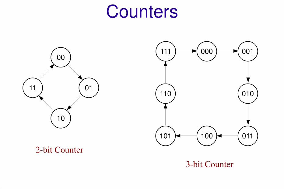
Counters
● A counter is a sequential circuit (aka. finite state machine) that cycles through a fixed sequence of states.
● The state of the counter is stored in Flip-Flops.
● An n-bit counter
– has n Flip-Flops
– can cycle through at most 2n states.
Spring 2011 ECE 331 - Digital System Design 3
Counters
00
10
0111010110
000 001111
011100101
2-bit Counter
3-bit Counter

Spring 2011 ECE 331 - Digital System Design 4
Counters
2-bit Counter
3-bit Counter
00
01
10
using only 3 states
using only 5 states
010
101 011
000
110

Spring 2011 ECE 331 - Digital System Design 5
Binary Counters
● An n-bit binary counter is a counter that cycles through all 2n states in ascending (or descending) order.
010110
000 001111
011100101
3-bit Binary Counter
Cycles through all 8 states
in ascending order

Spring 2011 ECE 331 - Digital System Design 6
Binary Counters: Design
1.Draw a state graph that specifies the desired sequence of the counter.
2.Construct a state table from the state graph.
One Flip-Flop for each bit in the state.
3.Derive a K-map from the state table for each Flip-Flop input.
Select the type of Flip-Flop to be used.
4.Determine the input equation(s) for each Flip-Flop.

Spring 2011 ECE 331 - Digital System Design 7
Binary Counters: Design
Example: State Table (using D FF)
Present State Next State FF Inputs
C B A C+ B+ A+ DC DB DA
0 0 0 0 0 1
0 0 1 0 1 0
0 1 0 0 1 1
0 1 1 1 0 0
1 0 0 1 0 1
1 0 1 1 1 0
1 1 0 1 1 1
1 1 1 0 0 0
Q+ = D
CharacteristicEquation:

Spring 2011 ECE 331 - Digital System Design 8
Binary Counters: Design
Example: K-maps (for D FF inputs)

Spring 2011 ECE 331 - Digital System Design 9
Binary Counters: Design
Example: Circuit Diagram (using D FF)

Spring 2011 ECE 331 - Digital System Design 10
Binary Counters: Design
Example: State Table (using T FF)
Q+ = T xor Q
CharacteristicEquation:
Present State Next State FF Inputs
C B A C+ B+ A+ TC TB TA
0 0 0 0 0 1
0 0 1 0 1 0
0 1 0 0 1 1
0 1 1 1 0 0
1 0 0 1 0 1
1 0 1 1 1 0
1 1 0 1 1 1
1 1 1 0 0 0
Excitation Table:
Q Q+ T
0 0 0
0 1 1
1 0 1
1 1 0

Spring 2011 ECE 331 - Digital System Design 11
Binary Counters: Design
Example: K-maps (for T FF inputs)

Spring 2011 ECE 331 - Digital System Design 12
Binary Counters: Design
Example: Circuit Diagram (using T FF)

Spring 2011 ECE 331 - Digital System Design 13
Binary Up-Down Counters
What constraints must be placed on the U and D control signals?

Spring 2011 ECE 331 - Digital System Design 14
Binary Up-Down Counters

Spring 2011 ECE 331 - Digital System Design 15
Loadable Counter with Enable

Spring 2011 ECE 331 - Digital System Design 16
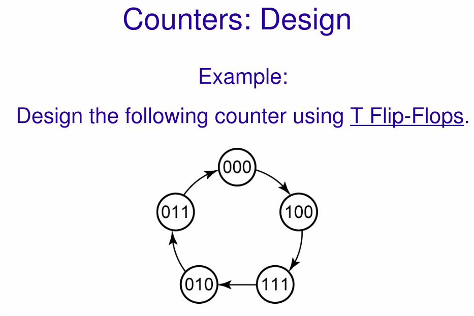
Counters: Design
1.Draw a state graph that specifies the desired sequence of the counter.
2.Construct a state table from the state graph.
One Flip-Flop for each bit in the state.
3.Derive a K-map from the state table for each Flip-Flop input.
Select the type of Flip-Flop to be used.
4.Determine the input equation(s) for each Flip-Flop.

Spring 2011 ECE 331 - Digital System Design 17
Counters: Design
Example:
Design the following counter using D Flip-Flops.

Spring 2011 ECE 331 - Digital System Design 18
Counters: Design
Example: State Table (using D FF)
Present State Next State FF Inputs
C B A C+ B+ A+ DC DB DA
0 0 0 1 0 0
0 0 1 x x x
0 1 0 0 1 1
0 1 1 0 0 0
1 0 0 1 1 1
1 0 1 x x x
1 1 0 x x x
1 1 1 0 1 0D = Q+
ExcitationEquation:

Spring 2011 ECE 331 - Digital System Design 19
Counters: Design
Example: K-maps (for D FF inputs)
DC DB DA

Spring 2011 ECE 331 - Digital System Design 20
Counters: Design
Example: Circuit Diagram (using D FF)
Spring 2011 ECE 331 - Digital System Design 21
Counters: Design
Example:
Design the following counter using T Flip-Flops.

Spring 2011 ECE 331 - Digital System Design 22
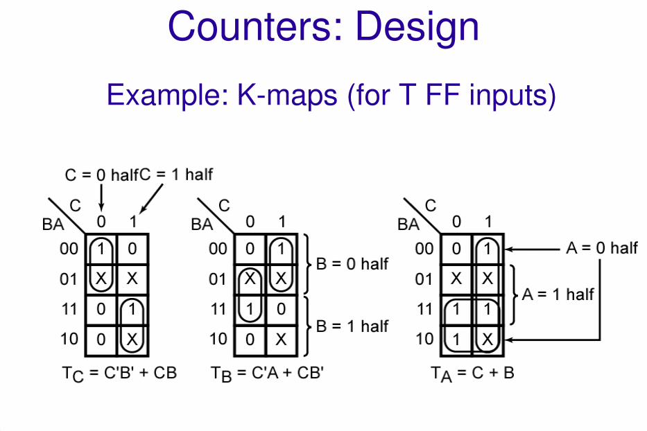
Counters: Design
Example: State Table (using T FF)
Present State Next State FF Inputs
C B A C+ B+ A+ TC TB TA
0 0 0 1 0 0
0 0 1 x x x
0 1 0 0 1 1
0 1 1 0 0 0
1 0 0 1 1 1
1 0 1 x x x
1 1 0 x x x
1 1 1 0 1 0T = Q xor Q+
ExcitationEquation:
Spring 2011 ECE 331 - Digital System Design 23
Counters: Design
Example: K-maps (for T FF inputs)

Spring 2011 ECE 331 - Digital System Design 24
Counters: Design
Example: K-maps (for T FF inputs)
We could derive TC , TB , and TA directly from the state table,
but it is often more convenient to plot next-state maps
showing C+, B+, and A+ as functions of C, B, and A, and then
derive TC , TB , and TA from these maps.

Spring 2011 ECE 331 - Digital System Design 25
Counters: Design
Example: Circuit Diagram (using T FF)

Spring 2011 26
Counters: Design
Example: Next States (for T FF inputs)
Although the original state table for the counter is not
completely specified, the next states of states 001, 101,
and 110 have been specified in the process of
completing the circuit design
110101

Spring 2011 ECE 331 - Digital System Design 27
Counters: Design
Example:
Design the following counter using JK Flip-Flops.

Spring 2011 ECE 331 - Digital System Design 28
Counters: Design
Example: Using JK Flip-Flops
Excitation Table:
Q Q+ J K
0 0 0 x
0 1 1 x
1 0 x 1
1 1 x 0

Spring 2011 ECE 331 - Digital System Design 29
Counters: Design
Example: State Table (using JK FF)
Present State Next State FF Inputs
C B A C+ B+ A+ JC KC JB KB JA KA
0 0 0 1 0 0
0 0 1 x x x
0 1 0 0 1 1
0 1 1 0 0 0
1 0 0 1 1 1
1 0 1 x x x
1 1 0 x x x
1 1 1 0 1 0

Spring 2011 ECE 331 - Digital System Design 30
Counters: Design
Example: K-maps (for JK FF inputs)

Spring 2011 ECE 331 - Digital System Design 31
Counters: Design
Example: Circuit Diagram (using JK FF)

Spring 2011 ECE 331 - Digital System Design 32
Questions?