ductile coupled reinforced concrete shear walls …...ductile coupled reinforced concrete shear...
TRANSCRIPT
Ductile Coupled Reinforced Concrete Shear Walls and Coupled Composite Steel Plate Shear Walls as Distinct
Seismic Force-Resisting Systems in ASCE 7
S. K. Ghosh. President S. K. Ghosh Associates LLC
Palatine, IL
Abstract
This paper discusses and provides background to the recognition of ductile coupled shear wall systems of reinforced concrete and coupled composite steel plate shear walls as distinct seismic force resisting systems in ASCE 7 Table 12.2-1, Design Coefficients and Factors for Seismic Force-Resisting Systems.
Introduction
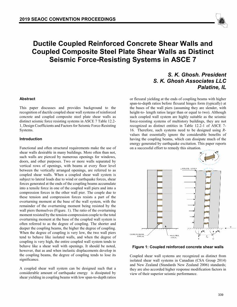
Functional and often structural requirements make the use of shear walls desirable in many buildings. More often than not, such walls are pierced by numerous openings for windows, doors, and other purposes. Two or more walls separated by vertical rows of openings, with beams at every floor level between the vertically arranged openings, are referred to as coupled shear walls. When a coupled shear wall system is subject to lateral loads due to wind or earthquake forces, shear forces generated at the ends of the coupling beams accumulate into a tensile force in one of the coupled wall piers and into a compression forces in the other wall pier. The couple due to these tension and compression forces resists a part of the overturning moment at the base of the wall system, with the remainder of the overturning moment being resisted by the wall piers themselves (Figure. 1). The ratio of the overturning moment resisted by the tension-compression couple to the total overturning moment at the base of the coupled wall system is often referred to as the degree of coupling. The shorter and deeper the coupling beams, the higher the degree of coupling. When the degree of coupling is very low, the two wall piers tend to behave like isolated walls, and when the degree of coupling is very high, the entire coupled wall system tends to behave like a shear wall with openings. It should be noted, however, that as and when inelastic displacements develop in the coupling beams, the degree of coupling tends to lose its significance.
A coupled shear wall system can be designed such that a considerable amount of earthquake energy is dissipated by shear yielding in coupling beams with low span-to-depth ratios
or flexural yielding at the ends of coupling beams with higher span-to-depth ratios before flexural hinges form (typically) at the bases of the wall piers (assuming they are slender, with height-to- length ratios larger than or equal to two). Although such coupled wall system are highly suitable as the seismic force-resisting systems of multistory buildings, they are not recognized as distinct entities in Table 12.2-1 of ASCE 7-16. Therefore, such systems need to be designed using R-values that essentially ignore the considerable benefits ofhaving the coupling beams, which can dissipate much of theenergy generated by earthquake excitation. This paper reportson a successful effort to remedy this situation.
Figure 1: Coupled reinforced concrete shear walls
Coupled shear wall systems are recognized as distinct from isolated shear wall systems in Canadian (CSA Group 2014) and New Zealand (Standards New Zealand 2006) standards; they are also accorded higher response modification factors in view of their superior seismic performance.
339
2019 SEAOC CONVENTION PROCEEDINGS
Ductile Coupled Structural (Shear) Wall System of ACI 318-19
Bertero wrote in 1977 (Bertero 1977): “Use of coupled walls in seismic-resistant design seems to have great potential. To realize this potential it would be necessary to prove that it is possible to design and construct “ductile coupling girders” and “ductile walls” that can SUPPLY the required strength, stiffness, and stability and dissipate significant amounts of energy through stable hysteretic behavior of their critical regions.”
Thus, discussion needs to focus on not on just coupled walls, but ductile coupled walls consisting of ductile shear walls and ductile coupling beams.
In the 2019 edition of ACI 318, a new system definition has been created to recognize the Ductile Coupled Structural (Shear) Wall (DCSW) system. The shear walls in such a system must be special structural walls in conformance with ACI 318-19 Section 18.10 and the coupling beams must comply with the detailing requirements in ACI 318-19 Section 18.10.7. There are additional important considerations.
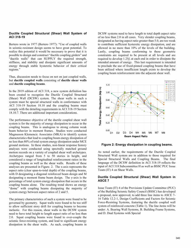
The performance objective of the ductile coupled shear wall system is for the majority of energy dissipation to occur in the coupling beams. This is analogous to strong column weak beam behavior in moment frames. Studies were conducted Magnusson Klemencic Associates (MKA) to identify system characteristics that lead to coupling beam energy dissipation of no less than 80% of total system energy dissipation under MCE ground motions. In these studies, non-linear response history analyses were conducted using spectrally matched ground motion records on a variety of coupled shear wall archetypes. Archetypes ranged from 5 to 50 stories in height, and considered a range of longitudinal reinforcement ratios in the coupling beams as well as the shear walls. Results of these analyses are presented in Figure. 2. The x-axis represents the aspect ratio (clear span-to-total depth) of the coupling beams, with D designating a diagonal reinforced beam design and M designating a moment frame beam design. The y-axis is the percentage of total system energy dissipation that occurs in the coupling beams alone. The resulting trend shows an energy “dome” with coupling beams dissipating the majority of system energy between aspect ratios of 2 and 5.
The primary characteristics of such a system were found to be governed by geometry. Squat walls were found to be too stiff to allow sufficient story drift for coupling beams to become inelastic. For this reason, shear walls in the DCSW system need to have total height to length aspect ratio of no less than 2.0. Squat coupling beams were found to over-couple the seismic force-resisting system, and lead to significant energy dissipation in the shear walls. As such, coupling beams in
DCSW systems need to have length to total depth aspect ratio of no less than 2.0 in all cases. Very slender coupling beams, designated as having aspect ratio greater than 5.0, are too weak to contribute sufficient hysteretic energy dissipation, and are allowed in no more than 10% of the levels of the building. Lastly, coupling beams conforming to these geometric constraints are required to be present at all levels and are required to develop 1.25fy at each end in order to dissipate the intended amount of energy. This last requirement is intended to preclude the use of fixed-pinned coupling beams that have been utilized where insufficient length exists to develop the coupling beam reinforcement into the adjacent shear wall.
Figure 2: Energy dissipation in coupling beams.
As noted earlier, the requirements of the Ductile Coupled Structural Wall system are in addition to those required for Special Structural Walls and Coupling Beams. The final language of the DCSW definition in ACI 318-19 reflects the input of ACI 318 Subcommittee H as well as BSSC PUC Issue Team (IT) 4 on Shear Walls.
Ductile Coupled Structural (Shear) Wall System in ASCE 7
Issue Team (IT) 4 of the Provisions Update Committee (PUC) of the Building Seismic Safety Council (BSSC) has developed a proposal, now approved, to add three line items to ASCE 7-16 Table 12.2-1, Design Coefficients and Factors for Seismic Force-Resisting Systems, featuring the ductile coupled wall system of reinforced concrete (Table 1). The line items will be under: A. Bearing Wall Systems, B. Building Frame Systems, and D. Dual Systems with Special
340
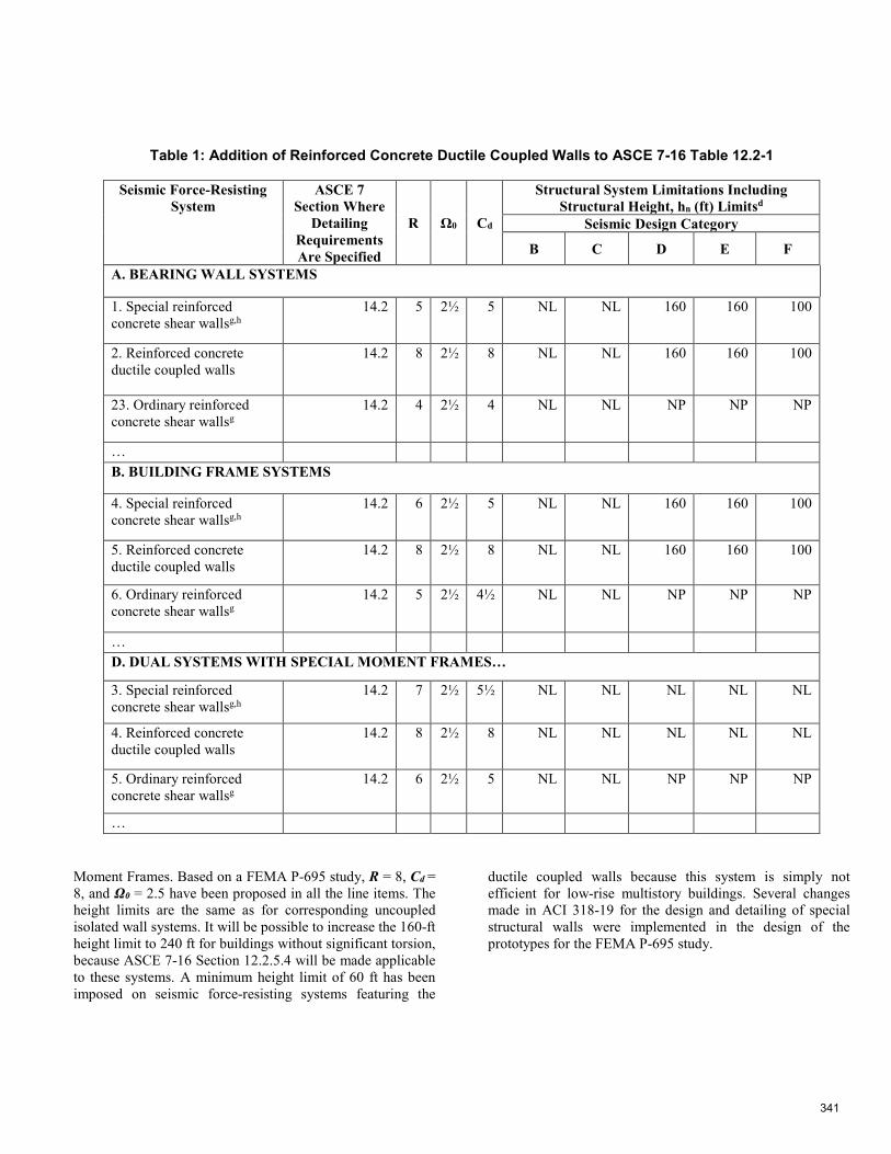
Table 1: Addition of Reinforced Concrete Ductile Coupled Walls to ASCE 7-16 Table 12.2-1
Seismic Force-Resisting System
ASCE 7 Section Where
Detailing Requirements Are Specified
R Ω0 Cd
Structural System Limitations Including Structural Height, hn (ft) Limitsd
Seismic Design Category
B C D E F
A. BEARING WALL SYSTEMS
1. Special reinforcedconcrete shear wallsg,h
14.2 5 2½ 5 NL NL 160 160 100
2. Reinforced concreteductile coupled walls
14.2 8 2½ 8 NL NL 160 160 100
23. Ordinary reinforcedconcrete shear wallsg
14.2 4 2½ 4 NL NL NP NP NP
… B. BUILDING FRAME SYSTEMS
4. Special reinforcedconcrete shear wallsg,h
14.2 6 2½ 5 NL NL 160 160 100
5. Reinforced concreteductile coupled walls
14.2 8 2½ 8 NL NL 160 160 100
6. Ordinary reinforcedconcrete shear wallsg
14.2 5 2½ 4½ NL NL NP NP NP
… D. DUAL SYSTEMS WITH SPECIAL MOMENT FRAMES…
3. Special reinforcedconcrete shear wallsg,h
14.2 7 2½ 5½ NL NL NL NL NL
4. Reinforced concreteductile coupled walls
14.2 8 2½ 8 NL NL NL NL NL
5. Ordinary reinforcedconcrete shear wallsg
14.2 6 2½ 5 NL NL NP NP NP
…
Moment Frames. Based on a FEMA P-695 study, R = 8, Cd = 8, and Ω0 = 2.5 have been proposed in all the line items. The height limits are the same as for corresponding uncoupled isolated wall systems. It will be possible to increase the 160-ft height limit to 240 ft for buildings without significant torsion, because ASCE 7-16 Section 12.2.5.4 will be made applicable to these systems. A minimum height limit of 60 ft has been imposed on seismic force-resisting systems featuring the
ductile coupled walls because this system is simply not efficient for low-rise multistory buildings. Several changes made in ACI 318-19 for the design and detailing of special structural walls were implemented in the design of the prototypes for the FEMA P-695 study.
341
(a) Planar Walls (6, 8, 12 Story) (b) Flanged Walls (18, 24, 30 Story) (c) Elevation View
Figure 3: Archetype floor plans and typical wall elevation view
FEMA P695 Studies Involving Ductile Coupled Structural (Shear) Walls
The proposed response modification factors for seismic force-resisting systems featuring the ductile coupled shear walls of reinforced concrete were validated using the FEMA P695 methodology (FEMA 2009). A series of forty-one coupled wall archetype buildings were designed for Seismic Design Category D in conformance with the most recent provisions of ASCE 7-16 and ACI 318-19. The archetypes considered addressed a range of variables expected to influence the collapse margin ratio, with the primary variables being building height (i.e., 6, 8, 12, 18, 24, and 30 stories), wall cross section (i.e., planar and flanged walls), coupling beam aspect ratio (łn/h) ranging from 2.0 to 5.0, and coupling beam reinforcement arrangement (diagonally and conventionally reinforced). The range of variables was chosen considering those used to define a ductile coupled structural wall system in ACI 318-19. The archetypes were optimally designed to have the minimum wall area (length and thickness), which is governed by shear amplification and the requirement that the nominal shear stress in walls sharing a common shear force not exceed a value of 8𝑓𝑓′𝑐𝑐𝐴𝐴𝑐𝑐𝑐𝑐. Typical floor plans and a wall elevation view are presented in Fig. 3.
Important design considerations adopted in the FEMA P695 study included four ACI 318-19 changes. The wall piers were designed per ACI 318-19 Section 18.10.3 considering wall shear force amplification by a factor of up to three, in an effort to reduce the likelihood of shear failure preceding flexural failure. Moreover, the wall drift capacity was checked per ACI 318-19 Section 18.10.6.2, to verify that wall piers have
sufficient drift capacity to resist Design Earthquake (DE) demands with a low (roughly 10%) probability of strength loss. Other implemented ACI 318-19 changes include ACI 318-19 Section 18.10.6.4, which requires improved wall boundary and wall web detailing (i.e, overlapping hoops if the boundary zone aspect ratio exceeds 2:1, crossties with 135-135 hooks on both ends, and 135-135 crossties on web vertical bars) as well as ACI 318-19 Section 18.10.2, which requires minimum wall boundary longitudinal reinforcement in order to limit the potential of brittle tension failures in walls that are lightly reinforced.
A conservative approach was used to define collapse for the FEMA P695 study, i.e., collapse was taken as a 20% drop in lateral strength. This approach is conservative because loss of axial load carrying capacity typically does not occur until lateral strength drops more significantly, e.g., an 80% drop. In some studies, axial failure has been assumed to occur at a specified roof drift ratio, which has been typically defined as 4 to 5% (NIST GCR-10-917-8), whereas, in this study, the conservative approach used resulted in roof drift ratios that were typically not more than 3%.
A system overstrength factor of Ω0 = 2.5 is proposed based on the nonlinear static pushover analysis results indicating that mean overstrength values of the performance groups range from 1.31 and 2.13. The proposed response modification factor R = 8 was validated based on incremental dynamic analysis results indicating that mean Adjusted Collapse Margin Ratio values of the performance groups range from 1.99 to 2.84 corresponding to collapse probabilities of less than ten percent based on using a conservative definition of collapse as noted
342
in the prior paragraph. The deflection amplification factor of Cd = 8 is proposed based on damping considerations and the assessment of median roof drift responses from design level earthquakes compared to design roof drifts. Overall, results of this study suggest that an overstrength factor Ω0 = 2.5 and a response modification factor R = 8 and a deflection amplification factor of Cd = 8 are appropriate seismic design parameters for RC Ductile Coupled Wall systems that are designed per ASCE 7-16 and ACI 318-19 provisions.
A report summarizing the FEMA P-695 study on Reinforced Concrete Ductile Coupled Walls is available (Tauberg et al, 2019).
The proposed seismic response modification factors for RC Ductile Coupled Walls have been validated using the FEMA P695 methodology. The collapse assessment studies include 37 archetype buildings designed for Seismic Design Category D [Dmax per FEMA P695] using ASCE 7-16 and ACI 318-19 provisions including new ACI 318-19 provisions that require wall shear amplification and a check that expected drift capacity exceeds the expected drift demand. The archetypes considered address a range of variables expected to influence the collapse margin ratio, with primary variables of building height (6 to 30 stories), wall cross section (planar and flanged/core), coupling beam aspect ratio (ln/h = 2.0 to 5.0), and coupling beam reinforcement arrangement (conventionally reinforced (CR) and diagonally reinforced (DR)). The range of variables was chosen considering those used to define a Ductile Coupled Wall system in ACI 318-19, as noted above.
A conservative approach was used to define collapse for the FEMA P695 study, i.e., collapse was taken as a 20% drop in lateral strength. This approach is conservative because loss of axial load carrying capacity typically does not occur until lateral strength drops more significantly, e.g., an 80% drop. In some studies, axial failure has been assumed to occur at a specified roof drift ratio, which has been typically defined as 4 to 5% (NIST GCR-10-917-8), whereas, in this study, the conservative approach used resulted in roof drift ratios that were typically not more than 3%.
A system overstrength factor of Ω0 = 2.5 is proposed based on the nonlinear static pushover analysis results indicating that mean overstrength values of the performance groups range from 1.31 and 2.13. The proposed response modification factor R = 8 has been validated based on incremental dynamic analysis results indicating that mean Adjusted Collapse
Margin Ratio values of the performance groups range from 1.99 to 2.84 corresponding to collapse probabilities of less than ten percent based on using a conservative definition of collapse as noted in the prior paragraph. The deflection amplification factor of Cd = 8 is proposed based on damping considerations and the assessment of median roof drift responses from design level earthquakes compared to design roof drifts. Overall, results of this study suggest that an overstrength factor Ω0 = 2.5 and a response modification factor R = 8 and a deflection amplification factor of Cd = 8 are appropriate seismic design parameters for RC Ductile Coupled Wall systems that are designed per ASCE 7-16 and ACI 318-19 provisions.
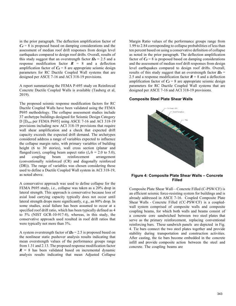
Composite Steel Plate Shear Walls
Figure 4: Composite Plate Shear Walls – Concrete Filled
Composite Plate Shear Wall—Concrete Filled (C-PSW/CF) is an efficient seismic force-resisting system for buildings and is already addressed in ASCE 7-16. Coupled Composite Plate Shear Walls - Concrete Filled (CC-PSW/CF) is a coupled-wall system comprised of composite walls and composite coupling beams, for which both walls and beams consist of a concrete core sandwiched between two steel plates that serve as the primary reinforcement, replacing conventional reinforcing bars. These sandwich panels are depicted in Fig. 4. Tie bars connect the two steel plates together and providestability during transportation and construction activities.After casting, the tie bars become embedded in the concreteinfill and provide composite action between the steel andconcrete. The coupling beams are
343
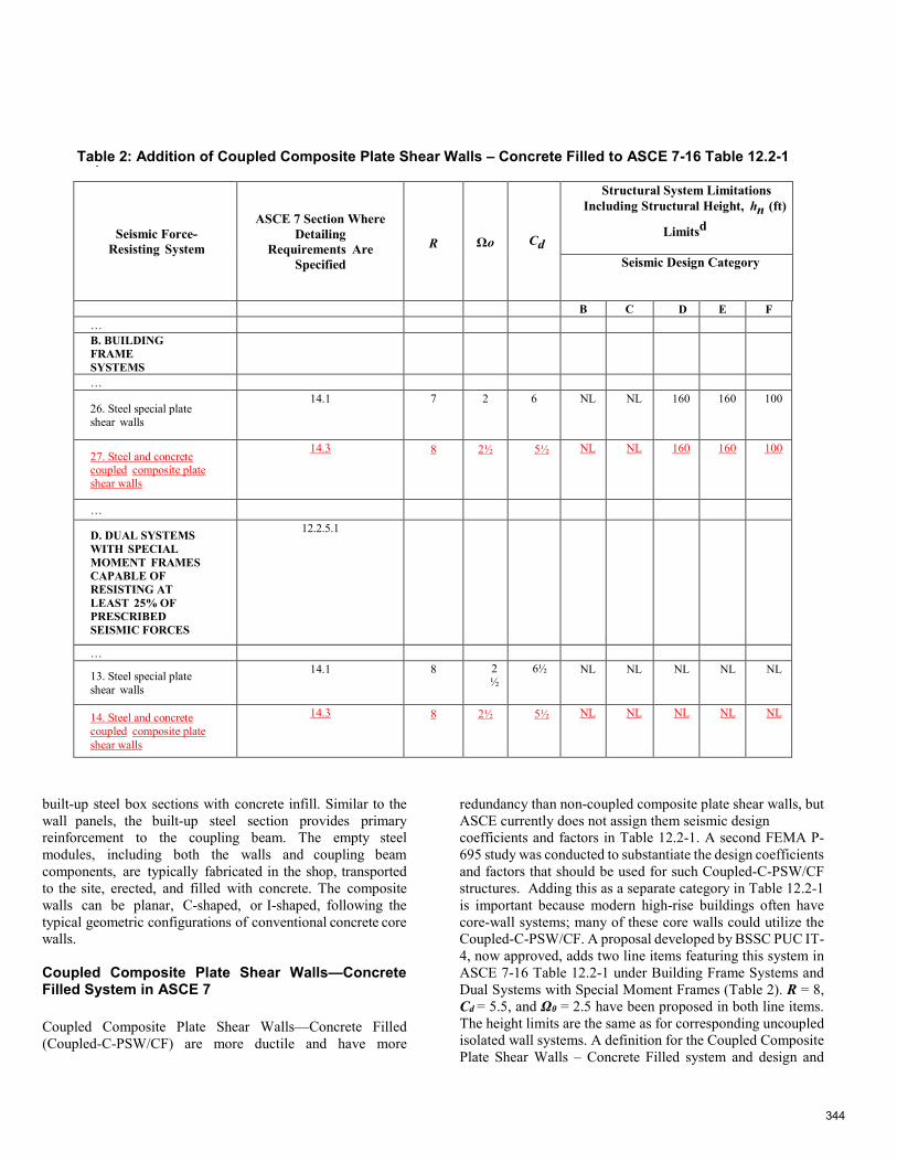
Table 2: Addition of Coupled Composite Plate Shear Walls – Concrete Filled to ASCE 7-16 Table 12.2-1
Seismic Force-Resisting System
ASCE 7 Section Where Detailing
Requirements Are Specified
R Ωo Cd
Structural System Limitations Including Structural Height, hn (ft)
Limitsd
Seismic Design Category
B C D E F … B. BUILDING FRAMESYSTEMS …
26. Steel special plate shear walls
14.1 7 2 6 NL NL 160 160 100
27. Steel and concrete coupled composite plate shear walls
14.3 8 2½ 5½ NL NL 160 160 100
…
D. DUAL SYSTEMS WITH SPECIAL MOMENT FRAMES CAPABLE OF RESISTING ATLEAST 25% OF PRESCRIBED SEISMIC FORCES
12.2.5.1
…
13. Steel special plate shear walls
14.1 8 2½
6½ NL NL NL NL NL
14. Steel and concrete coupled composite plate shear walls
14.3 8 2½ 5½ NL NL NL NL NL
built-up steel box sections with concrete infill. Similar to the wall panels, the built-up steel section provides primary reinforcement to the coupling beam. The empty steel modules, including both the walls and coupling beam components, are typically fabricated in the shop, transported to the site, erected, and filled with concrete. The composite walls can be planar, C-shaped, or I-shaped, following the typical geometric configurations of conventional concrete core walls.
Coupled Composite Plate Shear Walls—Concrete Filled System in ASCE 7
Coupled Composite Plate Shear Walls—Concrete Filled (Coupled-C-PSW/CF) are more ductile and have more
redundancy than non-coupled composite plate shear walls, but ASCE currently does not assign them seismic design coefficients and factors in Table 12.2-1. A second FEMA P-695 study was conducted to substantiate the design coefficients and factors that should be used for such Coupled-C-PSW/CF structures. Adding this as a separate category in Table 12.2-1 is important because modern high-rise buildings often have core-wall systems; many of these core walls could utilize the Coupled-C-PSW/CF. A proposal developed by BSSC PUC IT-4, now approved, adds two line items featuring this system in ASCE 7-16 Table 12.2-1 under Building Frame Systems and Dual Systems with Special Moment Frames (Table 2). R = 8, Cd = 5.5, and Ω0 = 2.5 have been proposed in both line items. The height limits are the same as for corresponding uncoupled isolated wall systems. A definition for the Coupled Composite Plate Shear Walls – Concrete Filled system and design and
344
detailing requirements for it are so far not given in AISC 360 or AISC 341. IT-4 has proposed and PUC has approved the addition of an ASCE 7 Section 14.3.5, which provides specific provisions for the definition and application of this Coupled-C-PSW/CF system, including details on the design philosophyand limits of applicability. It is anticipated that the provisionsin Section 14.3.5 will ultimately end up distributed in AISC360 and AISC 341 (2022). Rather than construct therequirements in Section 14.3.5 to modify the applicablesections of AISC 360 and AISC 341, it is presented as acompletely new comprehensive section in ASCE 7 formaximum clarity.
FEMA P695 Studies Involving Coupled Composite Plate Shear Walls—Concrete Filled System
A draft report summarizing the FEMA P-695 study on Coupled-C-PSW/CF is posted on the following website: http://purdue.edu/CE/Varma/secure (UserName: varmanet - Password: boilerup2019). This comprehensive report outlines the steps of the collapse assessment studies performed that have led to the proposed design provisions presented here. This study consisted of the following steps:
1. Development of a thorough set of design requirementsprescribed for Coupled-C-PSW/CF. These designrequirements are presented in detail in the proposed ASCE7 Section 14.3.5. Key aspects of the design requirementsinclude:
a. Limiting coupling beam span-to-depth aspectratios to the range of 3 to 5, to ensure flexurallydominant behavior and plastic hinging, andrequiring coupling beams with aspect ratiogreater than or equal to 3 for all stories of thebuilding, and less than or equal to 5 for at least90% of the stories of the building.
b. Calculation of design demands for the compositewalls using a capacity-limited seismic loadeffect, Ecl, obtained considering all the couplingbeams developing plastic hinges with capacitiesof 1.2 times their expected plastic moment;
c. Limits on plate slenderness ratio for walls andcoupling beam, to ensure development of plasticmoment;
d. Dimensional constraints, which when combinedwith the limits on plate slenderness ratio,contribute to ensuring substantial coupling beamssizes and coupling ratios;
e. Minimum height-to-length ratio of 4 for eachindividual wall of the coupled-walls system, todevelop flexurally-dominated wall deformationsand therefore engage all coupling beams into thesystem’s plastic mechanism;
f. Requirements for design of steel module underwet concrete condition, that govern the design ofties;
g. Amplification of calculated shear demand by afactor of 4, then comparison against providedshear strength (note that the shear strength forthese walls is large and rarely governs);
h. Specified minimum plastic rotation capacities forthe coupling beams, with adequacy of couplingbeam detailing to be based on experimentalevidence or demonstrated by other approvedmethods;
i. Specified wall-to-foundation connection demandrequirements;
j. Other requirements to achieve consistency withAISC-341 provisions, such as definition ofprotected zones, demand critical welds, and wallstiffness.
2. Design of 3-story, 8-story, 12-story, 18 story, and 22-storyarchetypes following the above design requirements, eachconsidering 4 different coupled-walls, resulting in a totalof 20 different archetypes. The archetypes were designedusing an R value of 8 and Cd value of 5.5. The 3, 8 and12-story archetype structures used planar composite walls,while the 18 and 22 story archetype structures used C-shaped walls.
3. Selection, validation, and calibration of the non-linearmodels used in the study. The numerical models for thestructures accounted for the various complexities offlexural behavior of the coupling beams and compositewalls. Two different sets of non-linear models wereconsidered and Incremental Dynamic Analyses (IDA)were performed in parallel, using these two different setsof non-linear models to assess sensitivity of the results.This contributed to enhanced confidence in the results andprovided a more robust validation of the proposed designprovisions and seismic design coefficients and factors. Forthe first IDA, walls and coupling beams were bothmodeled using a fiber model able to capture the effects ofconcrete cracking, steel yielding, local buckling, concretecrushing, and steel inelastic behavior up to fracture due tocumulative plastic strains and low-cycle fatigue. Athorough set of analyses were performed on examplestructures to ensure that the mechanics of the cross-sectionand member behavior were duly captured. For the secondset of IDA, a discrete hinge model was used for thecoupling beams, while the wall was modeled usinga fiber model with effective stress-strain relationshipsassigned based on 3D finite element analysis results thatimplicitly accounted for the effects of steel local buckling,yielding and fracture and concrete cracking, crushing andconfinement. For both sets of models, the numerical
345
models were benchmarked using experimental data available in the literature, and calibrated to match both the experimentally-obtained force-displacement and moment-rotation hysteretic curves, including full stiffness and strength degradation due to buckling, fracture, and other non-linear behavior. Models calibrated on experimental results for planar walls were used for the 3, 8 and 12 story archetypes, and on experimental results for C- shaped walls for the 18- and 22-story archetypes. Tofurther understand the mechanics of seismic response forthe structural system, additional studies were performed totrack the evolution of damage of selected archetypecoupled-walls to identify the onset and full development ofkey limit states, such as yielding and fracture of couplingbeams and walls. Non-linear finite element analyses wereconducted in parallel for these selected archetypes toprovide greater insights into the ultimate behavior of thestructural system, when subject to increasing severity ofground motion excitation.
4. Details of the parameters used in all non-linear time historydynamic analyses performed and the IDA for the two setsof non-linear models considered.
5. Findings from the Incremental Dynamic Analyses (IDA)performed, and resulting Adjusted Collapse Margin Ratio(ACMR) values for all of the archetypes considered.
Results from the FEMA P-695 studies indicated that all archetypes reached collapse at drifts greater than 5%, but all collapse margin ratios established in this study were conservatively calculated based on results obtained at 5% drift (i.e., at less than actual collapse points). Results of the FEMA P695 studies indicated that collapse margin ratios increased for the taller buildings, which is consistent with the fact that code-specified drift limits governed the design of the 18 and 22 stories archetypes. For all the archetypes considered, the lowest obtained calculated Adjusted Collapse Margin Ratios were 3.55, 3.54, 4.02, 4.75, and 6.5, respectively, for the 3-, 8-, 12-, 18-, and 22-story archetypes for the IDA conducted with the first set of non-linear models; corresponding values of 2.89, 3.04, and 4.28, respectively, were obtained for the 3-, 8-, and 12- story archetypes for the IDA conducted with the second setof non-linear models. All ACMR were calculated for a µT =3.0. These ACMRs were compared with the acceptableadjusted collapse margin ratio values of 1.96 and 1.56 forindividual archetypes and performance groups, respectively.These values are obtained for a total system collapseuncertainty, βTOT, calculated using a good rating for the designrequirements related collapse uncertainity, test data relatedcollapse uncertainity, and modelling related collapseuncertainity (incidentally, the ACMR would have been foundacceptable even if the ratings had been ―fair, or even mostly―poor). Overstrength factors, Ωo, for the archetypes were
found to be on the order of 2.0 to 2.5, and the Cd for the archetypes were found to be on the order of 5 to 6. Upon review of response time histories, the large ACMR obtained for overstrength factors of this magnitude were found to be attributable to the considerable period elongation that developed as the coupled beams progressively failed, and the fact that the walls hinged only at their base and had considerable shear strength along their height, precluding story-mechanisms.
Concluding Remarks
This paper discusses approved changes in Part 1 of the 2020 NEHRP Provisions, which would recognize a ductile coupled concrete shear wall system and a coupled composite steel plate shear wall system as distinct seismic force-resisting systems in ASCE 7 Table 12.2-1.
The NEHRP Provisions Part 1 changes are currently being considered for inclusion in ASCE 7-22. Expectations are that the systems will be included in ASCE 7-22 Table 12.2-1.
The ductile coupled concrete shear wall system is defined in ACI 318-19. The coupled composite steel plate shear wall system (Coupled Composite Plate Shear Walls – Concrete Filled) is defined in the new Section 14.3.5, approved for addition to ASCE 7-16 Chapter 14. Section 14.3.5 also provides design and detailing requirements for this system. It is expected that these requirements, possibly with some modifications, will become part of AISC 360 (AISC 2022) and AISC 341 (AISC 2022) and will eventually be deleted from ASCE 7 Chapter 14.
Acknowledgements
Although my name appears as the author because I chaired Issue Team (IT) 4 of the Provision Update Committee (PUC) of the Building Seismic Safety Council (BSSC), this paper is a compilation of contributions from various participants in the IT-4 effort. David Fields of Magnusson Klemencic Associates contributed the segment on definition of Ductile Coupled Structural Walls. The segment on P-695 studies involving that system is the contribution of Negin Taubert and John Wallace of UCLA. The information presented in the Coupled Composite Plate Shear Walls - Concrete filled is largely taken from the BSSC proposal to place this system in ASCE 7-16 Table 12.2-1. The proposal is primarily the work of Michel Bruneau, University of Buffalo, and Amit Varma, Purdue University. The author apologizes in advance for any distortions that may have crept into the material adopted from the various contributors.
346
I would like to acknowledge Bodhi Sunder Rudra of S. K. Ghosh Associates LLC for his outstanding help in preparing this manuscript.
References
ACI Committee 318, Building Code Requirements for Structural Concrete, ACI 318-19 and Commentary, ACI 318R-19, American Concrete Institute, Country Club Hills, MI, 2019.
AISC Committee on Specifications, Specification for Structural Steel Buildings, ANSI/AISC 360-22, American Institute of Steel Construction, Chicago, Illinois, 2022 [under development].
AISC Committee on Specifications, Seismic Provisions for Structural Steel Buildings, ANSI/AISC 341-22, American Institute of Steel Construction, Chicago, Illinois, 2022 [under development].
ASCE Committee 7, Minimum Design Loads and Associated Criteria for Buildings and Other Structures, ASCE 7-16, American Society of Civil Engineers, Reston, VA, 2017.
Bertero, V.V., “Seismic Behavior of R/C Wall Structural Systems,” Proceedings, Workshop on Earthquake-Resistant Reinforced Concrete Building Construction, University of California, Berkeley, July 1977, pp. 323-330.
CSA Group, Design of Concrete Structures, A 23.3.14, Mississanga, Ontario, Canada, 2014.
Federal Emergency Management Agency, Quantification of Building Seismic Performance Factors, FEMA P695, Washington, D.C., June 2009.
Kircher CA, Deierlein GD, Hooper JD, Krawinkler H, Mahin SA, Shing B, Wallace JW, Evaluation of the FEMA P-695 Methodology for Quantification of Building Seismic Performance Factors, Report NIST GCR-10-917-8, published November 15, 2010, 268 pp.
Kizilarslan, E., Seo, J., Broberg, M., Shafaei, S., Varma, A.H., Bruneau., M., (2018)., R-Factors for CoupledComposite Plate Shear Walls—Concrete Filled (Coupled-C-PSW/CF), Interim Project Report#2, Submitted to the Charles Pankow Foundation for CPFresearch grant #06-16.
Kizilarslan, E., Seo, J., Broberg, M., Shafaei, S., Varma, A.H., Bruneau., M., (2019)., Seismic Design Coefficients and Factors for Coupled Composite Plate Shear Walls, Concrete Filled (Coupled-C- PSW/CF), to be published.
Los Angeles Tall Buildings Structural Design Council, An Alternative Procedure for Seismic Analysis and Design of Tall Buildings Located in the Los Angeles Region, 2017 Edition, Los Angeles, June 2017
Standards New Zealand, Concrete Structures Standard, NZS 3101. 1&2: 2006, Wellington, New Zealand, 2006
Tauberg N, Kolozvari K, Wallace JW, Ductile Reinforced Concrete Coupled Walls: FEMA P695 Study, Draft Final Report (90%), November 2018, 106 pp.
347