seismic behaviour and design of innovative hybrid coupled ... seismic analysis. abstract in this...
TRANSCRIPT

Keywords: hybrid coupled shear walls, dissipative links, innovative steel-concrete hybrid structures, steel frames, seismic analysis.
ABSTRACT In this work innovative hybrid coupled shear walls (HCSW) are considered, their design is discussed, their efficiency and limitations evaluated by means of nonlinear static (pushover) analysis. Different numbers of storeys, wall geometries and design assumptions are studied in order to give an overview of situations of interest in European seismic prone areas. This study is part of a larger research project named INNO-HYCO (INNOvative HYbrid and COmposite steel-concrete structural solutions for building in seismic area) funded by the European Commission.
1 INTRODUCTION Steel and concrete composite structures are
common for buildings in seismic areas, conversely steel and concrete hybrid solutions are less diffused and many open problems and potentially interesting structural solutions require further investigation. In composite structures the deformation demands for the steel and concrete components are in the same range since concrete and steel are part of the same structural member. On the other hand, hybrid structures allow a more efficient design of the reinforced concrete structural elements as well as of the steel structural elements. In fact the deformation demands may be tailored to the capacity of the relevant materials. Thus, it becomes possible to define innovative steel and reinforced concrete hybrid systems for the construction of feasible and easy repairable earthquake-proof buildings through the full exploitation of the properties of both steel and concrete constructions.
Objective of the research project INNO-HYCO (INNOvative HYbrid and COmposite
steel-concrete structural solutions for building in seismic area), funded by the European Commission, is the study of steel-concrete hybrid systems obtained by coupling reinforced concrete elements (e.g., walls and shear panels) with steel elements (e.g., beams and columns). Such systems should permit to exploit both the stiffness of reinforced concrete elements, necessary to limit building damage under low-intensity earthquakes, and the ductility of steel elements, necessary to dissipate energy under medium- and high-intensity earthquakes. Such hybrid systems might represent a cost- and time-effective type of construction since: (i) simple beam-to-column connections could be used for the steel frame constituting the gravity-resisting part, (ii) traditional and well-known building techniques are required for the reinforced concrete and steel components.
Examples of hybrid structural systems are: (i) shear walls with steel coupling beams; (ii) systems made of traditional reinforced concrete shear walls coupled with moment resisting steel frames; (iii) composite walls made of steel frames with infill reinforced concrete panels. Such
Alessandro Zona, Graziano Leoni, Andrea Dall’Asta, Angela Scorpecci Università di Camerino, Scuola di Architettura e Design, Ascoli Piceno, Italy.
Teodora Bogdan, Hervé Degée Université de Liège, Département ArGEnCo, Liège, Belgium.
Seismic behaviour and design of innovative hybrid coupled shear walls

systems are considered in Eurocode 8 but only limited information is given for their design, e.g., connection between steel components and reinforced concrete components. Hybrid systems may suffer from some drawbacks distinctive of reinforced concrete shear walls and of moment-resisting steel frames. Shear walls are low redundant structures, their post-yielding behaviour is characterised by deformations localized at the base and expensive detailing is required to avoid concrete crushing. Furthermore, the high overturning moments require expensive foundations. In addition, reinforced concrete shear walls are very difficult to restore because the damage could be extended for more than one inter-storey height. On the other hand, moment-resisting steel components have expensive connections and large yielded zones that make repair complicated.
The research project INNO-HYCO aims at developing hybrid systems characterised by innovative conceptions and connection systems between steel and concrete components. Two main typologies are considered: (i) hybrid coupled shear wall (HCSW) systems, and (ii) steel frame with reinforced concrete infill walls (SRCW). In this paper only the HCSW systems are considered and selected results obtained by the research units of the University of Camerino (UNICAM) and of the University of Liège (ULG) are illustrated.
2 COUPLED SHEAR WALL SYSTEMS
2.1 Conventional systems Coupled shear wall systems obtained by
connecting reinforced concrete shear walls by means of beams placed at the floor levels constitute efficient seismic resistant systems characterised by good lateral stiffness and dissipation capacity. Coupling beams must be proportioned to avoid over coupling, i.e., a system that acts as a single pierced wall, and under coupling, i.e., a system that performs as a number of isolated walls. Extensive past research (e.g. Paulay and Priestley 1992) has led to well established seismic design guidelines for reinforced concrete coupling beams, typically deep beams with diagonal reinforcements, in order to satisfy the stiffness, strength, and energy dissipation demands. The diagonal reinforcement consists of relatively large diameter bars which must be adequately anchored and confined to avoid buckling at advanced limit states. Structural steel coupling beams (Figure 1) or steel-concrete
composite coupling beams provide a viable alternative (e.g. El-Tawil et al. 2010), particularly for cases with restrictions on floor height. In contrast to conventionally reinforced concrete members, steel/composite coupling beams can be designed as flexural-yielding or shear-yielding members. The coupling beam-wall connections depend on whether the wall boundary elements include structural steel columns or are exclusively made of reinforced concrete elements. In the former case, the connection is similar to beam-column connections in steel structures. In the latter case the connection is achieved by embedding the coupling beam inside the wall piers and interfacing it with the wall boundary element. In the past decade, various experimental programs (El-Tawil et al. 2010) were undertaken to address the lack of information on the interaction between steel coupling beams and reinforced concrete shear walls. However, coupled shear wall systems suffer from being difficult to be repaired after strong earthquakes. Design recommendations following the criteria of Performance or Displacement Based Design (PBD and DBD) and Force Based Design (FBD) are still missing or at their early stage of development (ASCE 2009).
Figure 1. Example of conventional hybrid coupled shear wall system connected to a gravity-resisting steel frame with pinned beam-to-column joints.
2.2 Innovative hybrid systems An example of innovative hybrid system is the
reinforced concrete shear wall with steel links depicted in Figure 2. The reinforced concrete wall carries almost all the horizontal shear force while the overturning moments are partially resisted by an axial compression-tension couple developed by the two side steel columns rather than by the individual flexural action of the wall alone. The reinforced concrete wall should remain in the elastic field (or should undergo limited damages) and the steel links connected to the wall should be the only (or main) dissipative elements. The connections between steel beams (links) and the

side steel columns are simple: a pinned connection ensures the transmission of shear force only while the side columns are subject to compression/traction with reduced bending moments. Such a mechanism allows the reduction of the negative effects of the reinforced concrete wall on the foundations.
Figure 2. Example of innovative hybrid coupled shear wall system connected to a gravity-resisting steel frame with pinned beam-to-column joints.
The structure is simple to repair if the damage is actually limited to the link steel elements. To this end, it would be important to develop a suitable connection between the steel links and the concrete wall that would ensure the easy replacement of the damaged links and, at same time, the preservation of the wall. As an alternative, links could include a replaceable fuse (El-Tawil et al. 2010) acting as a weak link where the inelastic deformations are concentrated while the remaining components of the system have to remain elastic. Clearly, the proposed hybrid system is effective as seismic resistant component if the yielding of a large number of links is obtained.
In this paper the problems encountered in a preliminary design of the above described innovative hybrid system based on the recommendations available in the Eurocodes are discussed using selected case studies. The relevant seismic performances of the designed structures are analysed in order to assess both potentiality and limitations encountered during the design for the proposed innovative HCSW systems.
3 DESIGN OF HCSW SYSTEMS
3.1 Case study Two case studies are considered: 4-storey and
8-storey steel frames with the same floor geometry as shown in Figure 3. For each floor the vertical loads are Gk = 6.5 kN/m2 and Qk = 3.0
kN/m2, while the floor total seismic mass is 1200 kNs2/m. Interstorey height is h = 3.40 m. The gravity-resisting frame has continuous columns (Table 1) pinned at the base. Beams (IPE500) are pinned at their ends. Steel S355 is used for columns, beams, and links. Selected materials for the reinforced concrete walls are concrete C25/30 and steel reinforcements S500. Table 1. Wide-flange cross sections of the columns of the vertical-resisting structure.
Storey # 4-storey case 8-storey case 8 - HE 220 B 7 - HE 220 B 6 - HE 300 B 5 - HE 300 B 4 HE 220 B HE 450 B 3 HE 220 B HE 450 B 2 HE 300 B HE 450 M 1 HE 300 B HE 450 M
8 m 8 m 8 m 8 m 8 m
8 m
8
m
8 m
8
m
8 m
HCSW HCSW
HCSW HCSW
HC
SW
HC
SW
HC
SW
HC
SW
HCSW
HCSW
HC
SW
HC
SW
Figure 3. Floor geometry of the benchmark structures with positions of the HCSWs.
The assumed seismic action is represented by the Eurocode 8 type 1 spectrum with ag = 0.25g and ground type C. Both verifications of the ultimate limit state (ULS) and of the damage limit state (DLS) are required.
3.2 Preliminary design Preliminary designs based on the conventional
force approach were made in order to identify possible optimal geometries. Two conditions were required in the design: (i) strength verification at ULS under the lateral forces derived from the design spectrum following the prescriptions in Eurocode 8, using the behaviour factor q = 3.3 given for composite structural system type 3 according to the definition in 7.3.1.e; (ii) stiffness verification at DLS under the
lateral forces assuming ν = 0.5 in formula 4.31 in paragraph 4.4.3.2 of Eurocode 8.
A large number of HCSWs with different dimensions of the reinforced concrete shear walls and link lengths were evaluated in this preliminary design stage by the ULG unit, as detailed in Deliverable 2.1 Part 1 “Description of considered cases, comparison of results and conclusions about the effectiveness in withstanding seismic actions” produced by ULG and included as annex in the INNO-HYCO mid-term report (Dall’Asta et al. 2012). The seismic behaviour of the most promising designs was assessed through nonlinear static (pushover) analysis and multi-record incremental nonlinear dynamic analysis as detailed in Deliverable 2.1 Part 2 “Seismic behaviour assessment by means of incremental dynamic analyses” included in the mid-term report (Dall’Asta et al. 2012). These most promising designs and relevant static and dynamic seismic analyses were presented in Zona et al. (2011, 2012), providing the following indications. In the 4-storey case it was observed that reinforcements in the concrete wall yield together with yielding in bending of the steel links in the first three storeys. Afterwards, further plastic dissipation is fostered by the successive yielding in bending of the links at the last storey. Then the peak strength of the reinforced concrete wall is achieved leading to the maximum sustained base shear before leading the bracing system to failure due to failure of the reinforced concrete wall. A different seismic performance was observed in the 8-storey design, where the steel links at all storeys yield in bending before any damage in the reinforced concrete wall. Afterwards reinforcements yields and shortly afterwards all links yield in shear. The concrete peak strain is attained but the bracing system is still able to exhibit global hardening. Collapse is reached when the link at the fifth storey fails in combined banding and shear. Despite these differences, pushover verifications are satisfied (capacity displacement larger than target displacement) in both case studies. In addition, it is observed that the HCSW systems designed are not prone to soft storey formation, even when the yielding of the steel links is not simultaneous, thanks to the contribution of the reinforced concrete wall.
3.3 Design based on rules inherited from other systems
The results obtained in this first design stage directed the research towards the definition of a design approach that inherits recommendation for
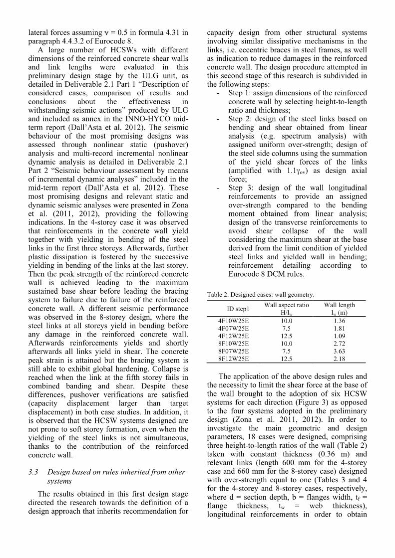
capacity design from other structural systems involving similar dissipative mechanisms in the links, i.e. eccentric braces in steel frames, as well as indication to reduce damages in the reinforced concrete wall. The design procedure attempted in this second stage of this research is subdivided in the following steps:
- Step 1: assign dimensions of the reinforced concrete wall by selecting height-to-length ratio and thickness;
- Step 2: design of the steel links based on bending and shear obtained from linear analysis (e.g. spectrum analysis) with assigned uniform over-strength; design of the steel side columns using the summation of the yield shear forces of the links (amplified with 1.1γov) as design axial force;
- Step 3: design of the wall longitudinal reinforcements to provide an assigned over-strength compared to the bending moment obtained from linear analysis; design of the transverse reinforcements to avoid shear collapse of the wall considering the maximum shear at the base derived from the limit condition of yielded steel links and yielded wall in bending; reinforcement detailing according to Eurocode 8 DCM rules.
Table 2. Designed cases: wall geometry.
ID step1 Wall aspect ratio H/lw
Wall length lw (m)
4F10W25E 10.0 1.36 4F07W25E 7.5 1.81 4F12W25E 12.5 1.09 8F10W25E 10.0 2.72 8F07W25E 7.5 3.63 8F12W25E 12.5 2.18 The application of the above design rules and
the necessity to limit the shear force at the base of the wall brought to the adoption of six HCSW systems for each direction (Figure 3) as opposed to the four systems adopted in the preliminary design (Zona et al. 2011, 2012). In order to investigate the main geometric and design parameters, 18 cases were designed, comprising three height-to-length ratios of the wall (Table 2) taken with constant thickness (0.36 m) and relevant links (length 600 mm for the 4-storey case and 660 mm for the 8-storey case) designed with over-strength equal to one (Tables 3 and 4 for the 4-storey and 8-storey cases, respectively, where d = section depth, b = flanges width, tf = flange thickness, tw = web thickness), longitudinal reinforcements in order to obtain

three values of wall over-strength (1.00 in cases labelled as R10, 1.25 in cases labelled as R12, 1.50 in cases labelled as R15). Reinforcement bars were concentrated in the lateral confined parts of the wall as for Eurocode 8 DCM rules. Significant quantities of longitudinal bars were required, especially for R15, in some cases exceeding Eurocode upper limits. Nevertheless, these design solutions were retained in the following seismic assessment phase in order to gain further insight into the influence of wall over-strength on the nonlinear behaviour up to failure. Table 3. Designed cases (4-storey): wide-flange links.
ID step1 link # d (mm)
b (mm)
tf (mm)
tw (mm)
4F07W25E 4 330 124 11.5 7.5 3 400 170 13.5 8.6 2 450 180 14.6 9.4 1 500 160 16.0 10.2 4F10W25E 4 330 124 11.5 7.5 3 400 170 13.5 8.6 2 450 180 14.6 9.4 1 500 174 16.0 10.2 4F12W25E 4 330 120 11.5 7.5 3 400 165 13.5 8.6 2 450 175 14.6 9.4 1 500 180 16.0 10.2
Table 4. Designed cases (8-storey): wide-flange links.
ID step1 link # d (mm)
b (mm)
tf (mm)
tw (mm)
8F07W25E 8 400 124 13.5 8.6 7 400 140 13.5 8.6 6 550 170 17.2 11.1 5 550 175 17.2 11.1 4 600 180 19.0 12.0 3 600 190 19.0 12.0 2 600 190 19.0 12.0 1 550 185 17.2 11.1 8F10W25E 8 400 130 13.5 8.6 7 400 160 13.5 8.6 6 550 180 17.2 11.1 5 550 180 17.2 11.1 4 600 185 19.0 12.0 3 600 200 19.0 12.0 2 600 210 19.0 12.0 1 600 185 19.0 12.0 8F12W25E 8 400 140 13.5 8.6 7 400 176 13.5 8.6 6 550 186 17.2 11.1 5 550 190 17.2 11.1 4 600 190 19.0 12.0 3 600 210 19.0 12.0 2 600 220 19.0 12.0 1 600 210 19.0 12.0
Thus, a total of nine designs involving 4-storey
frames (three wall geometries times three wall over-strengths) and a total of nine designs
involving 8-storey frames (again three wall geometries times three wall over-strengths).
4 SEISMIC BEHAVIOUR OF HCSW SYSTEMS
4.1 Modelling assumptions The seismic behaviour of the designed HCSW
systems was assessed through displacement-controlled nonlinear static analysis under applied lateral loads (pushover analysis), using the software FinelG. This software is being developed at the University of Liège for more than 40 years and is used for both academic activities and regular design purposes. It accounts for geometric and material non linear effects. For the sake of simplicity, the evaluation of the seismic performances is based on a plane model of a single HCSW connected to two continuous columns equivalent to the relevant parts of the gravity-resisting steel frame. An illustration of the model is given in Figure 4 for the 4-storey case. Loads and masses are those of the HCSW system as well as loads and masses from the relevant part of the gravity-resisting steel frame.
Figure 4. Numerical model.
The reinforced concrete shear wall is represented by frame elements using a fibre description for the behaviour of the concrete in the longitudinal direction, allowing an accurate estimation of the behaviour in bending and thus of the possible plastic hinge at the bottom of the wall. Reinforcement of the shear wall is assumed to be sufficient to avoid a shear failure of the wall. The steel shear links are modelled using nonlinear frame elements for the bending contribution as well as nonlinear shear springs introduced at mid span of each steel link to account for the shear deformability of the link and for the possible yielding in shear of the links. This additional shear spring is required for a
correct modelling of the system since most links are classified as intermediate according to EC8 definition and are thus more or less equally prone to shear or bending failure. Interaction between flexural and shear plastic deformations is considered in the post-processing of the results.
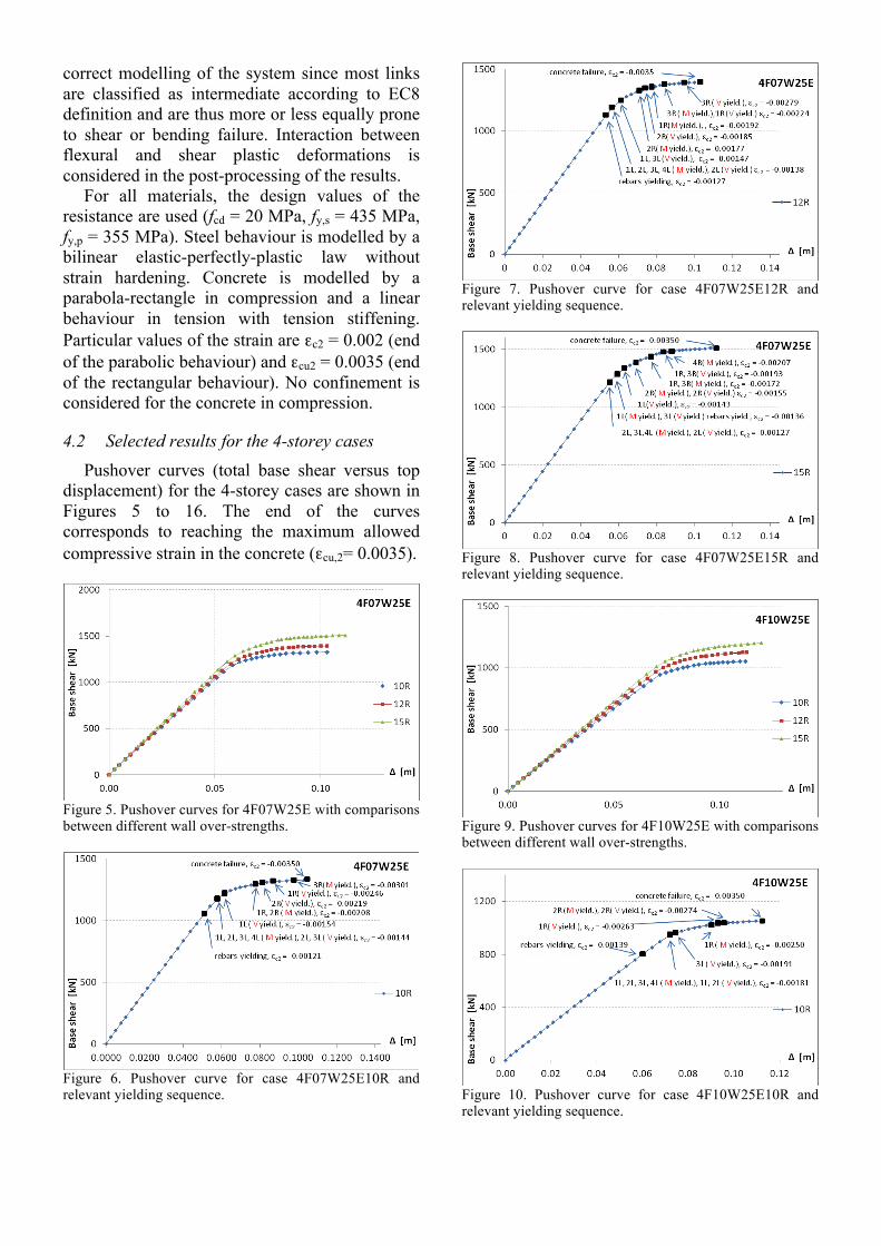
For all materials, the design values of the resistance are used (fcd = 20 MPa, fy,s = 435 MPa, fy,p = 355 MPa). Steel behaviour is modelled by a bilinear elastic-perfectly-plastic law without strain hardening. Concrete is modelled by a parabola-rectangle in compression and a linear behaviour in tension with tension stiffening. Particular values of the strain are εc2 = 0.002 (end of the parabolic behaviour) and εcu2 = 0.0035 (end of the rectangular behaviour). No confinement is considered for the concrete in compression.
4.2 Selected results for the 4-storey cases Pushover curves (total base shear versus top
displacement) for the 4-storey cases are shown in Figures 5 to 16. The end of the curves corresponds to reaching the maximum allowed compressive strain in the concrete (εcu,2= 0.0035).
Figure 5. Pushover curves for 4F07W25E with comparisons between different wall over-strengths.
Figure 6. Pushover curve for case 4F07W25E10R and relevant yielding sequence.
Figure 7. Pushover curve for case 4F07W25E12R and relevant yielding sequence.
Figure 8. Pushover curve for case 4F07W25E15R and relevant yielding sequence.
Figure 9. Pushover curves for 4F10W25E with comparisons between different wall over-strengths.
Figure 10. Pushover curve for case 4F10W25E10R and relevant yielding sequence.
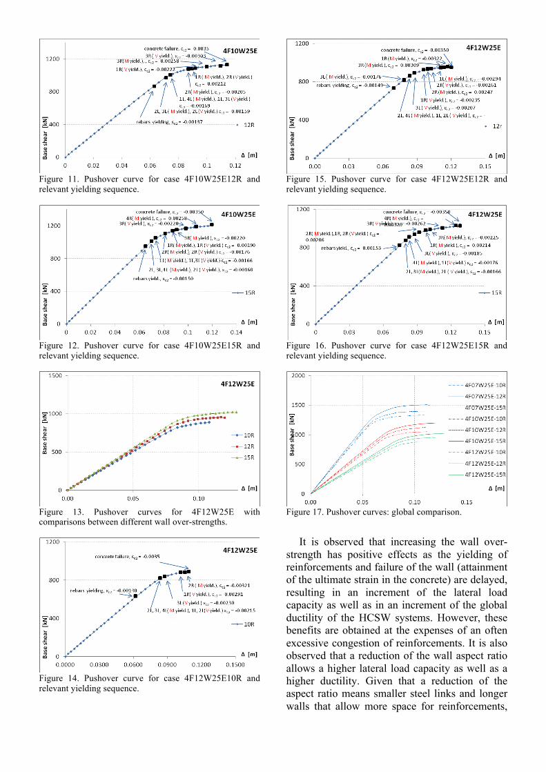
Figure 11. Pushover curve for case 4F10W25E12R and relevant yielding sequence.
Figure 12. Pushover curve for case 4F10W25E15R and relevant yielding sequence.
Figure 13. Pushover curves for 4F12W25E with comparisons between different wall over-strengths.
Figure 14. Pushover curve for case 4F12W25E10R and relevant yielding sequence.
Figure 15. Pushover curve for case 4F12W25E12R and relevant yielding sequence.
Figure 16. Pushover curve for case 4F12W25E15R and relevant yielding sequence.
Figure 17. Pushover curves: global comparison.
It is observed that increasing the wall over-
strength has positive effects as the yielding of reinforcements and failure of the wall (attainment of the ultimate strain in the concrete) are delayed, resulting in an increment of the lateral load capacity as well as in an increment of the global ductility of the HCSW systems. However, these benefits are obtained at the expenses of an often excessive congestion of reinforcements. It is also observed that a reduction of the wall aspect ratio allows a higher lateral load capacity as well as a higher ductility. Given that a reduction of the aspect ratio means smaller steel links and longer walls that allow more space for reinforcements,

the design should be based in practice on a limitation of the wall aspect ratio, possibly limited to suggested values H/lw ≤ 10.
4.3 Selected results for the 8-storey cases Pushover curves for the 8-storey cases are
shown in Figures 18 to 29. The observation made for the 4-storey cases can be repeated for these taller structures, where problems for the higher values of the wall aspect ratio H/lw are even more evident.
Figure 18. Pushover curves for 8F07W25E with comparisons between different wall over-strengths.
Figure 19. Pushover curve for case 8F07W25E10R and relevant yielding sequence.
Figure 20. Pushover curve for case 8F10W25E12R and relevant yielding sequence.
Figure 21. Pushover curve for case 8F07W25E15R and relevant yielding sequence.
Figure 22. Pushover curves for 8F10W25E with comparisons between different wall over-strengths.
Figure 23. Pushover curve for case 8F10W25E10R and relevant yielding sequence.
Figure 24. Pushover curve for case 8F10W25E12R and relevant yielding sequence.

Figure 25 Pushover curve for case 8F10W25E15R and relevant yielding sequence.
Figure 26 Pushover curves for 8F12W25E with comparisons between different wall over-strengths.
Figure 27. Pushover curve for case 8F12W25E10R and relevant yielding sequence.
Figure 28. Pushover curve for case 8F12W25E12R and relevant yielding sequence.
Figure 29. Pushover curve for case 8F12W25E15R and relevant yielding sequence.
Figure 30. Pushover curves: global comparison.
4.4 ULS and DLS verifications Outcomes in terms of pushover curves
presented in section 4.3 can be analyzed with respect to different ULS and DLS criteria. This allows in particular the calculation of specific performance points associated the activation of different limit states and hence, based on the N2 method proposed in Annex B of Eurocode 8, the calculation of the acceleration level corresponding to these performance points. In the present contribution, only preliminary assessments are given. The outcomes will be more deeply investigated in the next publications on the INNO-HYCO project. Three different limit states are taken into consideration: • ULS1: Maximum compressive strain
reached in the concrete shear wall. No confinement is conservatively taken into account. Accounting for the confining effect by imposing rules similar to those prescribed by EC8 for reinforced concrete walls could certainly improve the global behaviour of the system. • ULS2: Maximum rotation of the steel
links. In this preliminary assessment, indicative conservative values of the maximum possible rotation capacity are estimated according to the criteria proposed by FEMA 356 for seismic links

in eccentrically braced structures. The values must be adjusted in a next stage on the base of experimental test results to be carried out in the context of the INNO-HYCO project. • DLS: Maximum allowable inter-storey
drift. Associated values of the acceleration should be referred to acceleration level for DLS, smaller than the reference design value of 0.25g.
Results are provided in Table 5 in terms of maximum acceleration for the 4-storey cases. Additionally, Table 6 gives the values of the behaviour factor estimated from an equivalent bilinear curve on the base of the ductility. Table 5. Maximum sustainable accelerations from pushover curves and ULS/DLS criteria [in g].
ID step1 ULS1 ULS2 DLS 4F07W25E – 10R 0.22 0.19 0.11 4F07W25E – 12R 0.23 0.18 0.11 4F07W25E – 15R 0.26 0.14 0.07 4F10W25E – 10R 0.18 0.18 0.11 4F10W25E – 12R 0.18 0.18 0.09 4F10W25E – 15R 0.15 0.14 0.06 4F12W25E – 10R 0.14 > 0.14 0.08 4F12W25E – 12R 0.14 > 0.14 0.08 4F12W25E – 15R 0.13 > 0.13 0.06
Table 6. Behaviour factors at ag = 0.25g ID step1 10R 12R 15R
4F07W25E 2.77 2.59 2.30 4F10W25E 2.81 2.94 2.55 4F12W25E 1.86 2.15 1.97
5 CONCLUDING REMARKS A selection of results involving an innovative
steel-concrete hybrid coupled shear wall systems developed under the European research project INNO-HYCO was briefly illustrated. The analysis of the case studies designed according to the adoption of existing rules in the Eurocodes has highlighted the potentialities of the proposed innovative HCSW systems, namely: it is actually possible to develop a ductile behaviour where plastic deformation are attained in the steel links and limited damage occurs in the reinforced concrete wall; the interstorey drifts up to collapse are quite regular regardless of the non-simultaneous activation of the plastic hinges in the steel links and/or in the reinforced concrete wall; the adopted design approach based on well-known concepts and procedures already available in the Eurocodes give a promising starting design solution, although it appears that using the behaviour factor proposed by Eurocode 8 for composite walls overestimates the deformation capacity of the HCSW, in particular for short walls. On the other hand, the following issues
have been encountered: the designed solutions require additional studies to clarify the relationships between wall and links in order to provide additional design recommendations as integration of the Eurocodes; the slenderness of the HCSW systems needs to be better controlled in order to limit the negative effects of geometric nonlinear effects and improve the behaviour at the damage limit states. However, the sensitivity of the response to rotation capacity of the links and to confinement of the concrete needs also to be deeper studied, including also nonlinear time-history analysis. The upcoming developments of this research work involve the definition of a design procedure compatible with the current Eurocode 8 recommendations and in-depth experimental studies on the connections between reinforced concrete wall and replaceable dissipative steel links.
ACKNOWLEDGMENT Support for this research from the European
Commission, Research Fund for Coal and Steel, Steel Technical Group TGS 8 “Steel products and applications for building, construction and industry”, is gratefully acknowledged.
REFERENCES ASCE, 2009. Recommendations for seismic design of
hybrid coupled walls, ASCE Composite Construction Committee.
Dall’Asta, A., Leoni, G., Zona, A., 2011. INNO-HYCO INNOvative HYbrid and COmposite steel-concrete structural solutions for building in seismic area, First Annual Report.
Dall’Asta, A., Leoni, G., Zona, A., 2012. INNO-HYCO INNOvative HYbrid and COmposite steel-concrete structural solutions for building in seismic area, Mid-term Report.
El-Tawil, S., et al., 2010. Seismic design of hybrid coupled wall systems: state of the art, Journal of Structural Engineering, 136(7), 755-769.
FEMA 356 Guidelines for seismic rehabilitation of buildings, Federal Emergency Management Agency, USA, 2002.
Paulay, T., Priestley, M.J.N., 1992. Seismic design of reinforced concrete and masonry Buildings, Wiley.
Zona, A., Braham, C., Degée, H., Leoni, G., Dall’Asta, A., 2011. Innovative hybrid coupled shear walls for steel buildings in seismic areas. XXIII Italian Steel Structure Conference (CTA). 9-12 October, Ischia, Italy.
Zona A., Leoni, G. Dall’Asta, A., Braham, C., Bogdan, T., Degée, H., 2012. Behaviour and design of innovative hybrid coupled shear walls for steel buildings in seismic areas. 15th World Conference on Earthquake Engineering, 24-28 September, Lisbon, Portugal.