design provisions for shear walls
DESCRIPTION
Shear WallsTRANSCRIPT

RESEARCH AND DEVELOPMENT BULLETIN RD028.01D
Design Provisions for Shear Walls by A. E. Cardenas, J. M. Hanson,
W. G. Corley, and E. Hognestad
Reprinted with permission from Journal of the American Concrete Institute, Proceedings Vol. 70, No. 3, March 1973, pages 221-230.
L. PORTLAND CEMENT ASSOCIATION
CODE BACKGROUND PAPER
Background material used in preparing ACI 318-71
Design Provisions for Shear Wallsby A. E. Cardenas, J. M. Hanson,
W. G. Corley, and E. Hognestad
The background and development of SectionII. 16, Special Provisions for Walls, of the ACIBuilding Code (ACI 318-7 I ) is discussed. These pro-visions were found to predict satisfactorily thestrength of six high-rise and seven low-rise shearwalls tested at the laboratories of the PortlandCement Association, as well as the strength of wallspecimens tested by other investigators.
The results of the PCA experimental investiga-tions are summarized in an Ap endix. Thirteen
cl’rectangular shear walls were teste under combina-tions of lateral and axial loads. One of the speci-mens was subiected to ten cycles of load reversals.
Keywords: axial loads; building codes; cyclic loads; flexural
strength; high-rise buildings; reinforced concrete; reseerch;
shear strength; shear stress: sheer walls; structural design.
■ SHEARWALLS AREDEEP,relatively thin, vertical-ly cantilevered reinforced concrete beams. Theyare commonly used in structures to resist theeffects of gravity loads and story shears due towind or earthquake forces.
This paper summarizes background materialfor Section 11.16, Special Provisions for Walls, ofthe 1971 ACI Building Code.l The provisions areintended to ensure adequate shear strength. How-ever, other considerations such as flexuralstrength, energy absorption, lateral stiffness andreinforcement details are equally important toobtain satisfactory structural performance.
There has been relatively little research onthe strength and behavior of shear walls. Inves-tigators in Japan2-4have been concerned primarilywith the strength of low-rise shear walls sur-rounded by a reinforced concrete or steel frameand subjected to load reversals.
Japanese shear wall design provisions aredescribed in the Standards for Calculation of Re-inforced Concrete Structures.6 They are basedon the philosophy that the entire shear force is
to be carried by reinforcement, when a certainlimiting concrete shear stress is exceeded.
In the early 1950’s, Benjamin and Williams,o-gat the University of Stanford, conducted exten-sive static tests on low-rise shear walls surroundedby a reinforced concrete frame. Their proposeddesign equations had limited practical use due torestrictions in their applicability. An extensionof this investigation, dealing with dynamic loads,was conducted by Antebi, Utku and Hansen10atthe Massachusetts Institute of Technology. Dy-namic loads simulated were those due to, blastfrom atomic weapons rather than earthquakes.
Prior to publication of ACI 318-71,1 the onlyprovisions for design of shear walls in the UnitedStates were those contained in Uniform BuildihgCode?l
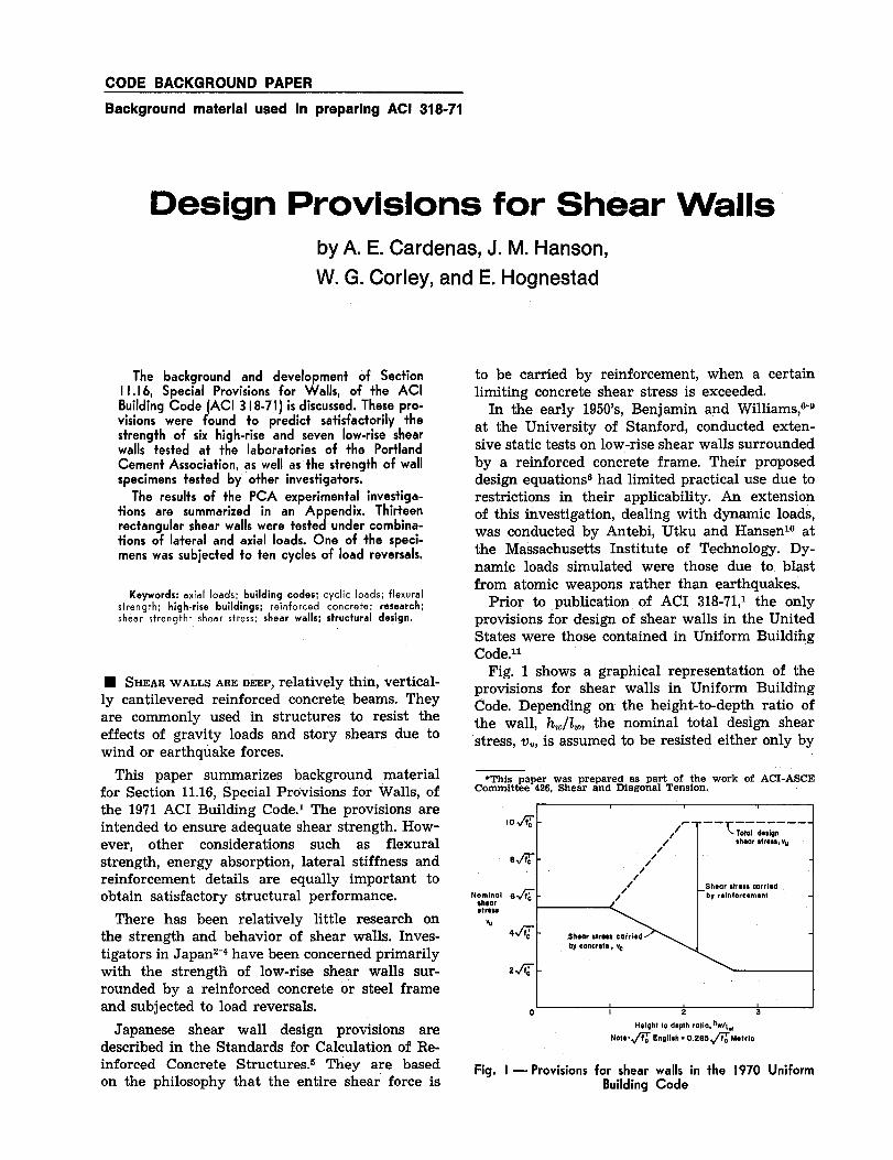
Fig, 1 shows a graphical representation of theprovisions for shear walls in Uniform BuildingCode, Depending on the height-to-depth ratio ofthe wall, h,,,/lu,, the nominal total design shearstress, v,,, is assumed to be resisted either only by
*This paper was prepared as part of the work of ACI-ASCECommittee426,Shear and Diagonal Tension.
low
t T T-- —.- ._
/- —- ~ota, ~,bn
./ shear stress,vu
Nominalshearetress
W
/em- /’/
,/’ _ Shear strms carriede~ - ./ by Enforcement
4~ - Shsar strws oairledby concrete, Vc
24 -
Io I z 3
Height to depth ratio, hw/lw
Noto, @ English. 0,265 @M6trio
Fig. I — Provisions for shear walls in the 1970 UniformBuilding Code

2 Design Provisions for Shear Walls
AC I member Alex E. Cardenas is a consulting engineer,
Lima, Peru. He raceived his BS in civil engineering in 1963
from Universidad National de Ingenieria, Lima, and his MS
degree and his PhD degree in 1965 and 1968 from
the University of Illinois, From 1968 to 1972 Dr. Cardenas
workad for PCA as a research engineer in the Structural
Development Section. Currently, he is a member of ACl -
ASCE Committee 426, Shear Diagonal Tension and AC I
Committee 442, Lateral F6rces.
ACI member John M. Hanson is assistant manager of
Structural Development Section, Research Development Div.,
Portland Cemant Association, Skokie, Ill. Currently, he isChairman of AC I Committee 215, Fatigue of Concrete, and
Secretary of ACI-ASCE Committee 426, Shear and Diagonal
Tension.
ACI member W. Gene Corlay is manager of Structural
Research Section, Resaarch and Development Div., Portland
Cemant Association, Skokie, Ill. He received his PhD from
University of Illinois in 1961, Dr. Corlay has done research
and was a development coordinator for U.S. Army Eng.
Rasearch and Development La b,, Ft. Belvoir, Va. Currently,
he is Chairman of AC I Committee 443, Concrete Bridge
Design, and Secretary of AC I-ASCE Committee 428, Limit
Design.
ACI member Eivind Hognestad is director of Engineering
Research, Raseerch and Development Div., Portland Cement
Association, Skokie, Ill. Dr. Hognestad has authored numerous
research papers as well as collaborating on saveral technical
committee reports. Currently, he is a member of AC I Com-
mittea 318, Standard Building Codas, and is also a member
of Board Committee on lnternatiWa ! Activities,
the concrete, or by the concrete and the horizontalreinforcement.
The nominal permissible shear stress carried by
the concrete, v,, on shear walls with low hw/2wratios is assumed similar to that in deep beams.It is taken as the straight-line lower bound ofresults of shear tests on deep beams without webreinforcement reported by dePaiva and Siess.lzThis shear stress is limited to 5.4+~~ for wallswith hJlw ratios of 1.0 or less. For hw/ lw ratios of2,7 or more, v, is taken equal to 2+V~, the valuerecommended for reinforced concrete beams inACI 318-63,13
Shear stress carried by the reinforcement isbased on results of shear tests on beams contain-ing web reinforcement reported by Slater, Lordand Zipprodt~Aas well as those reported by de-Paiva and Siess.12Based on these tests, it is as-sumed that vertical or horizontal web reinforce-ment in shear walls with hw/l,. ratios of 1.0 or lessdoes not appreciably increase the value of v,,above that of Vcattributed to the concrete. Conse-quently, their total shear stress is limited to 5,4+~~, Shear walls with h,,llw ratios of 2,0 or moreare considered to behave as beams; Total designshear stress for these walls is taken equal to 10+V7, as recommended in A~I 318-63,1’
While the UBC provisions represented an ad-vancement in design, additional work, includingthat by Crist,15Leonhardt and Walther,lQCardenasand Magura17and Cardenas, has led to separateprovisions for deep beams and shear walls inChapter 11 of ACI 318-71.1These provisions rec-ognize that there are important differences be-
tween deep beams and shear walls. First, deepbeams are usually loaded through the extremefibers in compression. Under these conditions,shear carried by the concrete in a member with-out web reinforcement is greater than the shearcausing diagonal tension cracking. Shear walls,however, are deep members loaded through stubsor diaphragms. This type of member, if it does notcontain web reinforcement, may fail at a shearequal to or only slightly greater than the shearcausing diagonal cracking.l* Second, deep beamsare not usually subjected to axial loads, whereasthe consideration of axial compression or tensionmay be important in shear walls.
Recognizing the limitations of the existing in-formation on the strength of shear walls, thePortland Cement Association started an experi-mental investigation in 1968.The highlights of thisinvestigation are described in the Appendix.
DEVELOPMENT
Flexural strength
OF DESIGN PROVISIONS
The experimental investigation demonstratedthe importance of considering the flexuralstrength of a shear wall. In many designs of shearwalls in high-rise buildings, use of the minimumamount of horizontal shear reinforcement requiredby the provisions of Section 11,16 of ACI 318-71,10.0025times the concrete area, will be adequate todevelop the flexural strength of the wall.
Using assumptions that are in accord with thosein Secti,on 10.2of AC!I318-71,the fIexural strengthof rectangular shear walls containing uniformlydistributed vertical reinforcement and subjectedto combined axial load, bending and shear, canbe calculated as:17
(1)
wherec cl+a
iii= 2q + 0.85~1
Mu = design resisting moment at section, in. lbA. = total area of vertical reinforcement at section,
sq in.f. = specified yield strength of vertical reinforce-
ment, psiL = horizontal length of shear wall, in.

ICA Research and Development Bulletin 3
distance from extreme compression fiber toneutral axis, in.distance from extreme compression fiber toresultant of tension force, in,thickness of shear wall, in.design axial load, positive if compression, lbspecified compressive strength of concrete, psi0.85 for strength jc’ up to 4000 psi (281.0 kgf/cm2) and reduced continuously to a rate of0.05 for each 1000psi (70 kgf /cm2) of strengthin excess of 4000 psi (281.0 kgf/cm2)
can be approximated as:
M,, = 0.5 AJU1‘(’+%)(1-8 ‘“
Based on results of the PCA investigation, Eq.(1) appears to satisfactorily predict the flexuralstrength of rectangular walls with an hW/_iWratioequal to or greater than 1.0,
Fig. 2 shows a comparison of Eq. (1) and (2)for different amounts of Grade 60 uniformlydistributed vertical reinforcement for f:= 4000psi (281.0 kgf/cmZ) and for two ratios of axialcompression, a = O and a = 0.25. The comparisonshows that for the case of pure bending, a = O,Eq. (2) is in good agreement with the more rigor-ous Eq, (1). In the case of a rather Iarge axiaIcompression, a = 0.25, the greatest difference isabout 5 percent. Accordingly, the use of the sim-plified Eq. (2) appears adequate for practical de-sign.
Shear strength
The distribution of lateral loads on shear wallsvaries with their height.lo-zo For example, undera lateral wind loading, this distribution may varyfrom nearly uniform on a wall in a tall buildingto a single concentrated force on a wall in a lowbuilding, Differences in lateral load distribution,geometry, and wall proportions lead to conditionsthat may make shear strength the controlling cri-terion in the design of low-rise shear walls.
As pointed out in the report of ACI-ASCE Com-mittee 326(426), Shear and Diagonal Tension,21American design practice is based on the premisethat shear capacity of concrete beams is made upof two parts. One part is the shear carried by con-crete, and the other part is the shear carried byweb reinforcement. Furthermore, these two partsare considered to be independent, so that webreinforcement is required only for that portionof the total shear that exceeds the limit of theshear carried by the concrete.
With the adoption of ACI 318-63, an additionalpremise became inherent in the shear designprovisions. This premise is that the shear carriedby the concrete is equal to the shear causing sig-nificant inclined cracking. This last assumptionunderscores the importance of the cracking shear.
1 t r
1I I I 1
H\I
1I
2.0I\\
FloxuralStrength,
A,fy~
1.0 -
\
\\\ fy= 60,000 psi (4219 kgf/cml)\\ f~. 4,000 p$i (281 kgf/cml)\\ 1
‘q’2$----::E,.(2)
,0
Amount of Uniformly Olstribut@d Vertical Reinforcement, p, parcont
Fig, 2 — Flexural strength of rectangular shear walls
Shear carried by concrete
It is generally ‘recognized that inclined crack-ing in concrete beams is of two types. In recentyears, these types of cracks have been describedas either “web-shear” or “flexure-shear,” The wayin which these cracks develop in reinforced andprestressed concrete beams has been described indetail elsewhere.22,23
The provisions of ACI 318-71 use Eq. (11-4) forcomputing the shear causing flexure-shear crack-ing in a reinforced concrete member. The limitingvalue of 3.5~~ for Eq. (11-4) serves as a meas-ure of the shear causing web-shear cracking. Inprestressed concrete beams, the shear causingflexure-shear or web-shear cracking is computedfrom Eq, (11-11) or (11-12), respectively. Eq. (11-12) predicts web-shear cracking as the shearstress causing a principal tensile stress of ap-proximately 4 V j: at the centroidal axis of thecross-section. Eq. (11-11) as originally deveIoped23predicts flexure-shear cracking as the shear stresscausing a flexural crack, corresponding to a flex-ural tensile stress of 6 ~ ~ to form at a sectionlocated distance d/2 from the section being in-vestigated, plus a small stress, 0.6V f:, intendedto represent the shear required to transform theinitiating flexural crack into a fully developedfIexure-shear crack.
It is important to recognize that Eq. (11-11) forprestressed concrete beams is applicable to rein-forced concrete beams subject to axial compres-sion. However, the results would be expected tobe conservative, because the shear stress requiredto transform an initiating flexural crack into aflexure-shear crack will usually be considerablygreater than 0.6~~, Recent worl#4 has attemptedto take this into account. It follows, therefore, thata similar approach applied to shear walls wouldbe conservative.
4 Desi@r Provisions for Shear Walls
t
Iofi ——— ———————= T.+al de,b”
sheer $tress,vu1
N:om;::l 6~ -
strew
_v_Shear stress carried
0,6twh 4~ -
Z%& -
,~
Moment to shear ratio, Mu/Vu
Note:~ English. 0.265 fiMotric
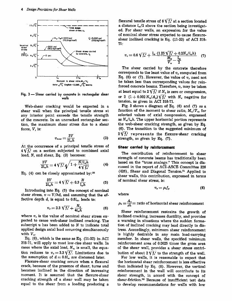
Fig. 3 —Shear carried bywcocrate in rectangular shear
Web-shear cracking would be expected in ashear wall when the principal tensile stress atany interior point exceeds the tensile strengthof the concrete. In an untracked rectangular sec-tion, the maximum shear stress due to a shearforce, V, is:
3V‘“” = 21wh
(3)
At the occurrence of a principal tensile stress of4 ~~ on a section subjected to combined axialload, N, and shear, Eq. (3) becomes:
Eq. (4) can be closely approximated by: 25
3V==4vT+o”3&- W
(5)
Introducing into Eq. (5) the concept of nominalshear stress, v = V/hd, and assuming that the ef-fective depth d, is equal to 0.81W,leads to:
V*= 3.3 w+& (6)
where VOis the value of nominal shear stress ex-pected to cause web-shear inclined cracking, Thesubscript u has been added to N to indicate totalapplied design axial load occurring simultaneouslywith Vu.
Eq. (6), which is the same as Eq. (11-32) in ACI318-71,will apply to most low-rise shear walls. Incases where the axial load, N,,, is small, the equa-tion reduces to VO= 3,3Vfi Limitations due tothe assumption of d = 0,81W are discussed later.
Flexure-shear cracking occurs when a flexuralcrack, because of the presence of shear, turns andbecomes inclined in the direction of increasingmoment, It is assumed that the flexure-shearcracking strength of a shear wall may be takenequal to the shear from a loading producing a
flexural tensile stress of 6 w% at a section locateda distance lw/2 above the section being investigat-ed. For shear walls, an expression for the valueof nominal shear stress expected to cause flexure-shear inclined cracking is Eq. (11-33) of ACI 318-71:
The shear carried by the concrete thereforecorresponds to the least value of v. computed fromEq. (6) or (7). However, the value of v. need notbe taken less than corresponding values for rein-forced concrete beams. Therefore, v. may be takenat least equal to 2 VT if N. is zero or compression,or 2 (1 + 0.002N./Ar) v= with N. negative fortension, as given in ACI 318-71.
Fig. 3 shows a diagram of Eq. (6) and (7) as afunction of the moment to shear ratio, Mu/VW, forselected values of axial compression, expressedas NJlwh, The upper horizontal portion representsthe web-shear cracking strength, as given by Eq.(6). The transition to the suggested minimum of2 w% rep resents the flexure-shear crackingstrength, as given by Eq. (7),
Shear carried by reinforcement
The contribution of reinforcement to shearstrength of concrete beams has traditionally beenbased on the “truss analogy.” This concept is dis.cussed in the report of ACI-ASCE Committee 326(426), Shear and Diagonal Tension.2’ Applied toshear walls, this contribution, expressed in termsof nominal shear stress, is:
v* = phfv (8)
where
= ~= ratio of horizontal shear reinforcementph ~~
Shear reinforcement restrains the growth ofinclined cracking, increases ductility, and providesa warning in situations where the sudden forma-tion of inclined cracking may”lead directly to dis-tress. Accordingly, minimum shear reinforcementis highly desirable in any main load-carryingmember. In shear walls, the specified minimumreinforcement area of 0.0025 times the gross areaof the shear wall, provides a shear stress contri-bution of about 2 VT to the strength of the wall.
For low walls, it is reasonable to expect thatthe horizontal shear reinforcement is less effectivethan indicated by Eq. (8). However, the verticalreinforcement in the wall will contribute to itsshear strength, in accord with the concept ofshear-friction.26 Because of insufficient test datato develop recommendations for walls with low

PCA Research and Development Bulletin 5
1 I f I , 1
Nominalshearstress
~0,8 lwh
v———————————————.“
I~Tafal dw!qn
8hnor stre8s,vu
8X
f =eo,ooo psiy (421 Ekgf/cma)
f:. 5,000 psi(352 kgf/cm’)
{
6@ -
Minimum shear stress
4a - k +-.
I H1225 Parssnt.—— —-— _
\ Reinforcement\
2Jz-\ .— ------ -—-—————
Concrete
o~Momentto@hear ratio, Mu/Vu
NotO, @ English. 0.265 ~Motric
Fig. 4 — Minimum shear stt;gth of rectangular shear
height to depth ratios, the amount of vertical re-inforcement required is equal to the amount ofhorizontal reinforcement when hw/lWis less than0,5. When hJL is greater than 2.5, the requiredminimum vertical reinforcement area is 0.0025.Between hW/lWratios of 0.5 and 2.5, the requiredminimum is determined by linear interpolation, asexpressed by Eq. (11-34) of ACI 318-71.
The shear capacity of rectangular shear wallscontaining minimum shear reinforcement is plot-ted in Fig. 4 as a function of the moment to shearratio, The curves have been plotted for a concretestrength, f,’, of 5000psi (350 kgf/cm2), and a yieldstress of the horizontal reinforcement, ~V,of 60,-000 psi (4200 kgf/cmz). The diagram shows thatfor these conditions, the minimum shear strengthof low-rise walls is of the order of 5.4~, andthat of high-rise walls is of the order of 4.1~.
Definition of nominai shear stress
In the design provisions, nominal shear stressis used as a measure of shear strength. Nominalshear stress, as defined by Eq. (11-31) of ACI318-71, is given by:
vu““”m (9)
wherevu =
* =
h=
d=
total applieddesignshearforce at sectioncapacity reductionfactor (Section 9.2, ACI318-71)thicknessof shearwalldistancefrom extremecompressionfiber toresultantof tensionforce
In shear walls, the effective depth, d, dependsmainly on the amount and distribution of verticalreinforcement. Fig. 5 shows the variation of theeffective depth with these variables. The valueof d = 0.8lWis also shown in Fig. 5. This value is
Depthratio~lw
I .0 -
0,s -
0.6 -
04–
0.2 -
1,..!
@@@”Reinforcement Oistributlons
I , , Io 001 0.02 003
Rat io of vertical reinforcement, 48/ lwh
Fig. 5 — Variation of effective depth in rectangular
shear walls
not necessarily conservative or unconservative,because the equations for shear attributed to theconcrete have been modified to account for theproposed value of d. The equation for shear at-tributed to the reinforcement depends on theability to effectively reinforce for shear over thevertical projection of the assumed inclined crack.
Limitation on uitimate shear stress
A limitation on ultimate shear stress is gen-erally considered to represent failure due tocrushing of concrete “struts” in beam webs,For reinforced concrete beams, ACI 318-631alimited the nominal ultimate shear stress to10W* There is some indicationz~that the shearstrength of a beam without web reinforcementmay decrease with increasing depth, Other testsloon beams with low a/d ratios indicate that thelimiting shear stress may be less than 10~.However, the tests reported in this paper indicatethat shear stresses up to 10~ can be attainedin walls with web reinforcement, even under loadreversals. Attainment of shear stresses of thismagnitude requires careful reinforcement de-tailing.
Comparison OF DESiGN Provisions WiTHTEST RESULTS
The proposed design provisions for shearstrength of shear walls have been compared withexperimental results reported by Muto andKokusho,2 Ogura, Kokusho and Matsoura~ Ben-jamin and Williams,6!7Antebi, Utku and Hansen,~Oand the PCA Laboratories.17 In the computationof nominal shear stress, the effective depth, d,was taken equal to the distance from the extremecompression force to the resultant of the tension
*O was not included here, so that the value is comparableto stresses in ACI 31S-71.
6 Design Provisions for Shear Walls
20~
15~
Measured
vu
Iofi
5&
c
nv
al
~vA
A
A
Vn❑
A A
A ❑ n
v A
A ❑
Vv ❑ A
n A❑
AAn
Calculated vu
Note*& English= 0.265 ~Metric
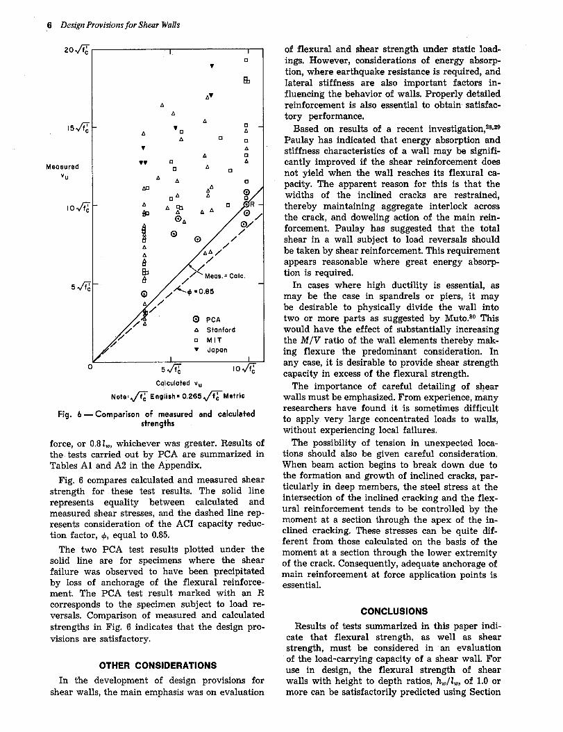
Fig. 6 — comparison of measured and calculated
strengths
force, or 0.8lW,whichever was greater, Results ofthe tests carried out by PCA are summarized inTables Al and A2 in the Appendix.
Fig. 6 compares calculated and measured shearstrength for these test results. The solid linerepresents equality between calculated andmeasured shear stresses, and the dashed line rep-resents consideration of the ACI capacity reduc-tion factor, ~, equal to 0.85.
The two PCA test results plotted under thesolid line are for specimens where the shearfailure was observed to have been precipitatedby loss of anchorage of the flexural reinforce-ment. The PCA test result marked with an Rcorresponds to the specimen subject to load re-versals. Comparison of measured and calculatedstrengths in Fig. 6 indicates that the design pro-visions are satisfactory,
OTHER CONSIDERATIONS
In the development of design provisions forshear walls, the main emphasis was on evaluation
of flexural and shear strength under static load-ings. However, considerations of energy absorp-tion, where earthquake resistance is required, andlateral stiffness are also important factors in-fluencing the behavior of walls. Properly detailedreinforcement is also essential to obtain satisfac-tory performance,
Based on results of a recent investigation,zsjzePaulay has indicated that energy absorption andstiffness characteristics of a wall may be signifi-cantly improved if the shear reinforcement doesnot yield when the wall reaches its flexural ca-pacity, The apparent reason for this is that thewidths of the inclined cracks are restrained,thereby maintaining aggregate interlock acrossthe crack, and doweling action of the main rein-forcement, Paulay has suggested that the totalshear in a wall subject to load reversals shouldbe taken by shear reinforcement, This requirementappears reasonable where great energy absorp-tion is required.
In cases where high ductility is essential, asmay be the case in spandrels or piers, it maybe desirable to physically divide the wall intotwo or more parts as suggested by Muto.s’JThiswould have the effect of substantially increasingthe M/V ratio of the wall elements thereby mak-ing flexure the predominant consideration. Inany case, it is desirable to provide shear strengthcapacity in excess of the flexural strength.
The importance of careful detailing of shearwalls must be emphasized. From experie~ce, manyresearchers have found it is sometimes difficultto apply. very large concentrated loads to walls,without experiencing local failures.
The possibility of tension in unexpected loca-tions should also be given careful consideration.When beam action begins to break down due tothe formation and growth of inclined cracks, par-ticularly in deep members, the steel stress at theintersection of the inclined cracking and the flex-ural reinforcement tends to be controlled by themoment at a section through the apex of the in-clined cracking. These stresses can be quite dif-ferent from those calculated on the basis of themoment at a section through the lower extremityof the crack. Consequently, adequate anchorage ofmain reinforcement at force application points isessential,
CONCLUSIONS
Results of tests summarized in this paper indi-cate that flexural strength, as well as shearstrength, must be considered in an evaluationof the load-carrying capacity of a shear wall. Foruse in design, the flexural strength of shearwalls with height to depth ratios, hW/tw,of 1.0 ormore can be satisfactorily predicted using Section
PCA Research and Development Bulletin 7
10.2, Assumptions, of ACI 318-71. Equations fordetermining the design flexural capacity of rec-tangular walls with uniformly distributed verticalreinforcement are presented in this paper,
For use in design, the shear strength of wallscan be satisfactorily predicted using Section 11.16,Special Provisions for Walls, ACI 318-71,
In the design of shear walls, considerations suchas energy absorption, lateral stiffness, and detail-ing of reinforcement need special attention,
ACKNOWLEDGMENTS
This investigation was carried out at the StructuralDevelopment Section, Portland Cement Association.
Mr. D, D. Magura, former PCA Research Engineer,initiated the experimental investigation. Laboratorytechnicians B, J, Doepp, B. W. Fullhart, W. H. Graves,W, Hummerich, Jr., and O. A. Kurvits performed thelaboratory work.
REFERENCES
1, ACI Committee 318, “Building Code Requirementsfor Reinforced Concrete (ACI 318-71) ,“ American Con-crete Institute, Detroit, 1971, 78 pp.
2. Muto, Kiyoshi, and Kokusho, $eiji, “ExperimentalStudy on Two-Story Reinforced Concrete Shear Walls,”Tmn.sactions, Architectural Institute of Japan (Tokyo),No. 4’7, Sept. 1953, ‘7 pp.
3. Ogura, K.; Kokusho, S,; and Matsoura, N., “Teststo Failure of Two-Story Rigid Frames with Walls, Part24, Experimental Study No. 6,” Report No. 18, Archi-tectural Institute of Japan, Tokyo, Feb. 1952.
4, Tsuboi, Y.; Suenaga, Y.; and Shigenobu, T., “Fun-damental Study on Reinforced Concrete Shear WallStructures—Experimental and Theoretical Study ofStrength and Rigidity of Two-Directional StructuralWalls Subjected to Combined Stresses M, N. Q.,” T~an++actions, Architectural Institute of Japan (Tokyo), No.131, Jan, 1967. (Foreign Literattwe Stud~ No. 536, Port-land Cement Association, Skokie, Nov. 1967.)
5. “Standards for Calculation of Reinforced ConcreteStructures,” Architectural Institute of Japan, Tokyo,1962. (in Japanese)
6. Williams, Harry A., and Benjamin, Jack R., “In-vestigation of Shear Walls, Part 3—Experimental andMathematical Studies of the Behavior of Plain andReinforced Concrete Walled Bents Under Static ShearLoading,” Department of Civil Engineering, StanfordUniversity, July 1953, 142 pp.
7, Benjamin, Jack R., and Williams, Harry A., “In-vestigation of Shear Walls, Part 6-Continued Experi-mental and Mathematical Studies of ReinforcedConcrete Walled Bents Under Static Shear Loading:’Department of Civil Engineering, Stanford University,Aug. 1954, 59 pp.
8. Benjamin, Jack R., and Williams, Harry A., “TheBehavior of One-Story Reinforced Concrete ShearWalls,” P~oceedings, ASCE, V. 83, ST3, May 1957, pp.1254-1 to 1254-49. Also, Transactions, ASCE, V. 124,1959, pp. 669-708,
9, Benjamin, Jack R., and Williams, Harry A., “Be-havior of One-Story Reinforced Concrete Shear WallsContaining Openings,” ACI JOURNAL, Proceedings V. 55,No. 5, Nov. 1958, pp. 605-618.
10.: Antebi, J.; Utku, S.; and Hansen, R. J., “The Re-sponse of Shear Walls to Dynamic Loads,” DAS~-1 160,
Department of Civil and Sanitary Engineering, Massa-chusetts Institute of Technology, Cambridge, Aug. 1960.
11. Uniform Building Code, International Conferenceof Building Officials, Pasadena, 1967 and 1970 editions.
12, dePaiva, H. A. Rawdon, and Siess, Chester P.,“Strength and Behavior of Deep Beams in Shear,”Proceedings, ASCE, V, 91, ST5, Part 1, Oct. 1965, pp.19-41.
13, ACI Committee 318, “Building Code Requirementsfor Reinforced Concrete (ACI 318-63) ,“ American Con-crete Institute, Detroit, 1963, 144 pp.
14. Slater, W. A,; Lord, A. R,; and Zipprodt, R. R.,“Shear Tests of Reinforced Concrete Beams,” Tech-nologic Paper No, 314, National Bureau of Standards,Washington, D. C., 1926, pp. 387-495.
15. Crist, Robert A., “Shear Behavior of Deep Rein-forced Concrete Beams—V. 2: Static Tests,” AFWL-TR-67-61, The Eric H. Wang Civil Engineering ResearchFacility, University of New Mexico, Albuquerque, Oct.1967. Also, Proceedings, RILEM International Sym-posium on the Effects of Repeated Loading on Materialsand Structures (Mexico City, Sept. 1966), Instituto deIngenieria, Mexico City, 1967, V. 4, Theme 4, 31 pp.
16. Leonhardt, Fritz, and Walther, Rene, “Deep Beams(Wandartige Traeger) ,“ Bulletin No. 178, DeutscherAusschuss fur Stahlbeton, Berlin, 1966, 159 pp.
17, Cardenas, A. E., and Magura, D. D., “Strength ofHigh-Rise Shear Walls—Rectangular Cross Sections,”Response of Multistory Concrete Structures’ to LateralForces, SP-36, American Concrete Institute, Detroit,1973, pp. 119-150.
18. Zsutty, Theodore, “Shear Strength Prediction forSeparate Categories of Simple Beam Tests,” ACIJOURNAL, Proceedings V. 68, No. 2, Feb. 1971, pp. 138-143.
19. Khan, Fazlur R., and Sbarounis, John A., “Inter-action of Shear Walls and Frames,” Proceedings, ASCE,V. 90, ST3, June 1964, pp. 285-335.
20, “Design of Combined Frames and Shear Walls,”Advanced Enginee~ing Bulletin No. 14, Portland CementAssociation, Skokie, 1965.
21. ACI-ASCE Committee 326(426), “Shear and Di-agonal Tension,” ACI JOURNAL, Proceedings V. 59, No.1, Jan. 1962, pp. 1-30; No. 2, Feb. 1962, pp. 277-334; andNo. 3, Mar. 1962, pp. 353-396.
22, MacGregor, James G., and Hanson, John M., “Pro-posed Changes in Shear Provisions for Reinforced andPrestressed Concrete Beams,” ACI JOURNAL, Proceed-ings V. 66, No. 4, Apr. 1969, pp. 276-288.
23. Sozen, Mete A., and Hawkins, Neil M., Discussionof “Shear and Diagonal Tension” by ACI-ASCE Com-mittee 326 (426), ACI JOURNAL, Proceedings V. 59, No. 9,Sept. 1962, pp. 1341-1347.
24. Mattock, Alan H., “Diagonal Tension Cracking inConcrete Beams with Axial Forces,” Proceedings, ASCE,V. 95, ST9, Sept. 1969, pp. 1887-1900.
25, ACI Committee 318, “Commentary on BuildingCode Requirements for Reinforced Concrete (ACI 318-63) ,“ SP-10, American Concrete Institute, Detroit,1965, 91 pp.
26. Mast, Robert F., “Auxiliary Reinforcement inConcrete Connections,” Proceedings, ASCE, V. 94, ST6,June 1968, pp. 1485-1504.
27. Kani, G, N. J., “How Safe Are Our Large Rein-forced Concrete Beams?,” ACI JOURNAL, ProceedingsV. 64, No. 3, Mar. 1967, pp. 128-141.
28. Paulay, Thomas, “The Coupling of ReinforcedConcrete Shear Walls,” P~oceedings, Fourth World Con-

8 Desi@ Provisions for Shear Walls
ference on Earthquake Engineering, Santiago, Chile,Jan, 1969, V. 1, 11. B2-75 to B2-90.
29. Paulay, Thomas, “Coupling Beams of ReinforcedConcrete Shear Walls,” Proceedings, ASCE, V. 97, ST3jMar. 1971, pp. 843-862.
30. Muto, Kiyoshi, “Recent Trends in High-RiseBuilding Design in Japan,” Proceedings, Third worldConference on Earthquake Engineering, New Zealand,1965, V. 1, pp. 118-147.
APPENDIXPCA investigation
In this investigation, thirteen large rectangular shearwall specimens have been tested under static combi-nations of axial load, bending, and shear. Six of thespecimens, SW-1 through SW-6, represented walls inhigh-rise buildings,ls The remaining seven, SW-7through SW-13, represented walls inlow-rise buildings.One of the low-rise shear walls, SW-13, was subjectedto ten cycles of load reversals.
All test specimens were rectangular reinforced con-crete members with a thickness h=3 in. (7,92 cm) anda depth ZW= 8 ft 3 in. (1,90 m), For convenience, thespecimens were tested as horizontal cantilevered beams.However, in describing the specimens, reference isalways made to the position of a wall in an actualbuilding rather than its position during testing, Fig. Alshows the test setup for one of the high-rise walls.
Loading rods extending through the test floor were usedto apply the simulated static lateral forces. Post-ten~ioning rods, running horizontally in the photo, wereused to apply the simulated gravity loads. The portionof the specimen to the right of the support representsa foundation providing full restraint to the base of thewall,
Shear wall specimens SW-1 through SW-6 representthe lower portion of a shear wall in a frame-shear wallstructural system.zo!zl The height of the specimen cor-responds to the distance between the base of the walland its point of contraflexure. It was assumed that 50percent of the total shear force at the base of the wallwould be applied at the point of contraflexure. Theremaining 50 percent was uniformly distributed be-tween the point of contra flexure and the base of thewall.
Four of the six high-rise shear wall specimens SW-1,SW-2, SW-3 and SW-6 had a height of 21 ft (6.40 m),the other two, SW-4 and SW-5, were 12 ft (4.09 m)high, An axial compressive stress of about 420 psi(29,5 kgf/cmz) was applied, The main variable wasthe amount and distribution of the vertical reinforce-ment, Horizontal shear reinforcement equal to 0.27percent of the concrete cross-sectional area was provid-ed in each of the six specimens.
Six of the seven specimens representing low-riseshear walls, SW-7 throughSW-12,were subjectedto a
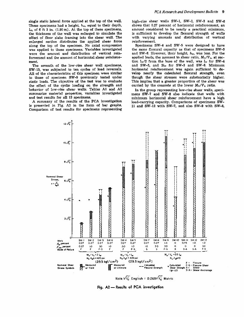
single static lateral force applied at the top of the wall.These specimens had a height, hw, equal to their de@h,L, of 6 ft 3 in. (1,90 m). At the top of these specimens,the thickness of the wall was enlarged to simulate theeffect of floor slabs framing into the shear wall. Theenlarged section distributes the applied shear forcealong the top of the specimen. No axial compressionwas applied to these specimens. Variables investigatedwere the amount and distribution of vertical rein-forcement and the amount of horizontal shear reinforce-ment.
The seventh of the low-rise shear wall specimens,SW-13, was subjected to ten cycles of load reversals.All of the characteristics of this specimen were similarto those of specimen SW-9 previously tested understatic loads. The objective of the test was to evaluatethe effect of the cyclic loading on the strength andbehavior of low-rise shear walls. Tables Al and A2summarize material properties, variables investigatedand test results for all 13 specimens.
A summary of the results of the PCA investigationis presented in Fig. A2 in the form of bar graphs.Comparison of test results for specimens representing
PCA Research and Development Bulletin 9
high-rise shear walls SW-L SW-2, SW-3 and SW-6showsthat 0.27percentof horizontalreinforcement,anamountconsideredto be nearly a practicalminimum,is sufficient to develop the flexural strengthof wallswith varying amounts and distribution of verticalreinforcement.
SpecimensSW-4 and SW-5 were designed to havethe same flexural capacity as that of specimensSW-3and SW-6. However,their height,h~, was less.For theappliedloads,the momentto shearratio,M./Vu, at sec-tion LJ2 from the base of the wall, was L for SW-4and SW-5, and 21t0 for SW-3 and SW-6. Minimumhorizontal reinforcement was again sufficient to de-velop nearly the calculated flexural strength, eventhough the shear stresses were substantially higher.This implies that a greater proportion of the shear wascarried by the concrete at the lower Mu/Vu ratio.
In the group representinglow-rise shearwalls,speci-mens SW-7 and SW-8 also indicate that walls withminimumhorizontalshear reinforcementhave a highload-carryingcapacity.Comparisonsof specimensSW-11 and SW-12 with SW-7, and also SW-9 with SW-8,
12W
lo~
SK
Nominol Shear
Stress,6&
‘=&h
44
2~
oMark
Phlpercent
n
:~
*
///////////////
~T,1IIIIIIIIII,1IIIIIIIIII
/
/
/
/
/* /
/
/
/
/
/
/
/
/
/
5
/
/
SW-1 SW-2 SW-3 SW-6 SW-4 SW-5 SW-7 SW-B SW-9 Sw-lo Sw-1 I SW-12 SW-130.27 0.27 0.27 0.27 0,27 0.27 0.27 0.27 1.0 0 0.75 1.0 I ,0
Pvw,percent 0.27 Lo 3,0 Lo 3.0 1.0 Lo 30 30 0 0 0 3,0
Mode of Failure-
sw
s F-S s S-A s-A F-Sv
MU IVU=21W Mu/vu .tw Mu/vu =0.5 ~
Nu /~h=420 psi Nu/~h. 420 psi Nu @=O
(29.5 kgf/c m2) (29.5 kgf/cm2)Nominal Shear
t?
F, FlexureMeasured
r
Meosureti Calculated * CalculatedStress Symbols
F-S = Flexure-ShearatYield at Ullimote ‘- Flexural Strength Shear Strength S . Shear
(+. 1.0} S-13 : Shear-Anchorage
Note,fl English = 0.265fi Metric
Fig. A2 — Results of PCA investigation

10 Design Provisions for Shear Wads
TABLE Al — DIMENSIONS AND MATERIAL PROPERTIES OF TEST SPECIMENS
Axial
stress
Nullwb
psi
415
430
420
420
425
430
None
None
None
None
None
None
None
ReinforcementConcreteMark
SW-I
SW-2
SW-3
SW-4
SW-5
SW-6
Sw-’l
SW-8
SW-9
SW-IO
SW-U
SW-12
SW-13
Height
~ 20mpre8sive
strength
f.’
psi
7420
0880
6780
6740
5900
5950
6240
8180
6240
5850
5540
5570
8200
Vertical Horizontal
Ratio~~*
0,0027
0.0100
0.0200
0.0200
o,0220t
o.0230t
o.0230t
0!0300
0.0300
0.0185$
0.0230~
0.0230$
0.0300
Yieldstress
J:i
Ratio
pb
0.0027
0.0027
0.0027
0.0027
0.0027
0.0027
0.0027
0.0027
0.0100
None
0.0075
0.0100
0.0100
Yieldstress
$s1
81,300
81,000
60,000
80,000
80,000
70,000
80,000
67;500
60,000
None
85,000
65,000
66,000
21.0
21.0
21,0
12.0
12.0
21.0
8,25
8.25
6.25
6.25
6.25
8.25
6.25
860
650
615
535
565
590
630
565
820
585
535
530
630
60,200
65,400
88,000
60,000
60,000
63,000
65,000
65,000
85,000
65,000
65,000
85,000
04,500
*PV=+&, where A. = total area of vertical reinforcement, tw= 75 in. and h = 3 in..r.-tOne-third of total vertical reinforcement concentrated within a distance h /10 from either
extremity of cross section (amount of reinforcement in interior region p.w = 0.01).$One-half of total vertical reinforcement concentrated within a distance 2s0/10 from either
extremity of cross section (oflW = 0).To convert to S1 equivalen~: 1 ft & 0,305 m; 1 psi = 0,0703 kgf/cmz.
TABLE A2 – TEST RESULTS
Calculatedparameters
MeasuredCalculated
Flexural strength Shear strength
Ratiod/lw,
at
Momentto shear
ratioM.IV.
at lW/2frombase
Measured Calcu-Iatedt
v. v,
v%
Observedmode offailurd
Mark Measured~oment, Mu,
at basekip-ft
3alculated*moment,M.
at base
kip-ft
Shear atlW/2 from
base
0.44
0.70
1.13
L12
1.15
1,20
1.55
1,82
1,07
1.30
0.89
0,94
1.00
Shear, V.,atlw/2,
kips
Momentat thebase
1.07
1.04
0.90
0,95
0.96
1.02
0.74
0.79
0!95
0.81
0.86
0.93
0.89
Sw-1SW-2
SW-2
SW-4
SW-5
SW-6
SW-7
SW-8
SW-9
Sw-lo
Sw-11
SW-12
SW-135
Flexure
Flexure
Flexure-Shear
Flexure
Flexure-Shear
Flexure
Shear
Shear
Flexure-Shear
Shear
Shear-Anchorage
Shear-Anchorage
Flexure-Shear
2.OIW
2.o110
2.OIW
I.olw
1.Olw
2.01+0
0.51W
o.5110
0.5110
0.51W
o,5110
0.51W
0.51W
—.
0.58
0.62
0.71
0.71
0.78
0,76
0.74
0.65
0.85
0s4
0!94
0.84
0.65
406
876
1073
1077
1078
1178
729
801
954
429
858
925
888
379
850
1200
1139
1121
1154
880
1009
1000
700
1000
1000
1000
26.5
41.4
66.0
108.6
108.6
72.5
118,7
128.1
152.7
88,7
137,0
146.0
142.1
1.7
2.8
4.5
7.4
7.6
5.3
6.2
9.1
10.7
4.3
6.7
9.4
10.0
3.9
4,0
4.0
6.6
6.8
4,4
5.3
5.6
10.0
3.3
9.8
10.0
10.0
*Based on compressive concrete 14miting strain of 0.003, strain compatibilityy and measured material properties.&d#ated from proposed shear strength equations.
ed is 0,8L0 or greater.$SW-13 was subjected to 10 cycles of load reversals._To convert to S1 equivalents: 1 kip = 453.6 kgf; Vfo’, U.S. = 0.285Vfi metric.
PCA R esearch and Development Bulletin 11
indicate that additional horizontal shear reinforcementwill further increase capacity.
Comparisons of SW-8 with SW-7, and SW-9 with SW-12, show that the lateral load carrying capacity aIsoincreases with vertical web reinforcement. However,these observations are qualified somewhat by the ob-servation that specimens SW-9, SW-11 and SW-12 didnot fail in shear. In addition, at failure there wasyielding of the vertical reinforcement in all of thesespecimens,
The ultimate shear stress of SW-10, a specimen withno horizontal or vertical web reinforcement, was4.3 Vz.
Specimen SW-13 was subjected to a total of tencycles of increasing levels of load reversals. Compari-son of this specimen with SW-9, a physically similarspecimen that was subjected to one-directional loading,shows no significant decrease in strength, Both of thesespecimens developed shear stresses of the order of10I f.’.
Notation
= shear span, distance between concentratedload and face of support, in.
= gross area of section, sq in.
= total area of vertical reinforcement at sec-tion, sq in.
= area of horizontal shear reinforcement withina distance, s, sq in.
= distance from extreme compression fiber toneutral axis, in.
= distance from extreme compression fiber toresultant of tension force, in.
172
~c’
fll
hh.
LaMuN.
qs
‘UC
vuvVW
;p
‘#
ph
W
= square root of specified compressive strengthof concrete, psi
= specified compressive strength of concrete,psi
= specified yield strength of reinforcement,psi
= thickness of shear wall, in.= total height of wall from its base to its
top, in.= depth or horizontal length of shear wall, in.= design resisting moment at section, in,/lb= design axial load at section, positive if com-
pression, lb= A,~Vllwhfc’= vertical spacing of horizontal shear rein-
forcement, in,= nominal permissible shear stress carried by
concrete, psi= nominal total design shear stress, psi= shear force at a section, lb= total applied design shear force at section,
lb= fv./lwhfc’= jv/87,000= 0,85 for strength f.’ up to 4000 psi (281,0
kgf/cmz) and reduced continuously to a rateof 0.05 for each 1000 psi (70.3 kgf/cmz) ofstrength in excess of 4000 psi (281.0 kgf /cm2).
= capacity reduction factor (Section 9.2 ACI318-71)
= A.lsh= A&)h
This paper was rece;ved by the Institute May 15, 1972.
Thispublicationis basedon the facts,tests,andauthoritiesstatedherein.It isintendedfor the use of professionalpersonnelcompetentto evaluatethe significanceandlimita-tionsof thereportedfindingsandwhowillacceptresponsibilityfor theapplicationof thematerialit contains.Obviously,the PortlandCementAssociationdisclaimsanyandallresponsibilityfor applicationof the statedprinciplesor for the accuracyof anyof thesourcesotherthanworkperformedor informationdevelopedby theAssociation.
~------------------------------- ------------------ --------
L
?I I:II KEYWORDS: axial loads,buildingcodes,cyclicloads,flexuralstrength,high- ~I rise buildings,reinforcedconcrete,research,shearstrength,shearstress,shear I
iI
walls,structuraldesign. !I
IABSTRACT: Discusses background and development of Sec. 11.16, Special !
1I Provisions for Walls, of the AC!IBuildingCode (ACI 318-71). Theseprovi- ~I sionswerefound to predictsatisfactorilythe strengthof six high-riseand ~iI seven low-riseshearwallstestedat the PCA laboratories,as well as the II1 strengthof wallspecimenstestedby otherinvestigators.Resultsof thePCA ~
investigationsaresummarizedin theAppendix.iI ~I REFERENCE: Cardenas, A. E.; Hanson, J.M.;Corley, W.G.; andHognestad, ,! E.,Des&nProvisions for Shear Walls (RD028.OID), PortlandCementAssoci- ;II ation, 1975.ReprintedfromJournal of the American Concrete Institute, Pro- 1
ceedingsVol. 70, No. 3, March1973,pages221-230.I
iI
II
i
1II
i ------------------------- ----------------------- ----------- i
PCA R/D Ser. 1494

mlPORTLAND CEMENT I I ASSOCIATIONAn organization 01 cement manufacturers to improve and extend the uses of portfand cement and concrete through scientific research, engineering fiefd work, and market development.
Printed in U.S.A,
5420 Old Orchard Road, skokie, Illinois 60077
RD028.OID