ditec dab105 - ditecentrematic.com · 8.3 assembling the left-hand articulated arm 16 9. automation...
TRANSCRIPT
Ditec DAB105Swing doors(translation of the original instructions)
www.entrematic.com
Technical Manual
IP2159EN • 2018-09-26
2 IP2
15
9E
N
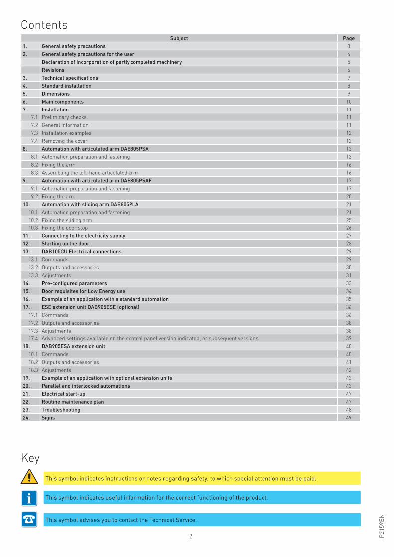
Contents
Key
Subject Page
1. General safety precautions 3
2. General safety precautions for the user 4
Declaration of incorporation of partly completed machinery 5
Revisions 6
3. Technical specifications 7
4. Standard installation 8
5. Dimensions 9
6. Main components 10
7. Installation 11
7.1 Preliminary checks 11
7.2 General information 11
7.3 Installation examples 12
7.4 Removing the cover 12
8. Automation with articulated arm DAB805PSA 13
8.1 Automation preparation and fastening 13
8.2 Fixing the arm 16
8.3 Assembling the left-hand articulated arm 16
9. Automation with articulated arm DAB805PSAF 17
9.1 Automation preparation and fastening 17
9.2 Fixing the arm 20
10. Automation with sliding arm DAB805PLA 21
10.1 Automation preparation and fastening 21
10.2 Fixing the sliding arm 25
10.3 Fixing the door stop 26
11. Connecting to the electricity supply 27
12. Starting up the door 28
13. DAB105CU Electrical connections 29
13.1 Commands 29
13.2 Outputs and accessories 30
13.3 Adjustments 31
14. Pre-configured parameters 33
15. Door requisites for Low Energy use 34
16. Example of an application with a standard automation 35
17. ESE extension unit DAB905ESE (optional) 36
17.1 Commands 36
17.2 Outputs and accessories 38
17.3 Adjustments 38
17.4 Advanced settings available on the control panel version indicated, or subsequent versions 39
18. DAB905ESA extension unit 40
18.1 Commands 40
18.2 Outputs and accessories 41
18.3 Adjustments 42
19. Example of an application with optional extension units 43
20. Parallel and interlocked automations 43
21. Electrical start-up 47
22. Routine maintenance plan 47
23. Troubleshooting 48
24. Signs 49
iThis symbol indicates instructions or notes regarding safety, to which special attention must be paid.
This symbol indicates useful information for the correct functioning of the product.
This symbol advises you to contact the Technical Service.
3IP2
15
9E
N
1. General safety precautions
This installation manual is intended for qualified personnel only.
Installation, electrical connections and adjustments must be performed in accordance with
Good Working Methods and in compliance with the present standards. Read the instructions
carefully before installing the product.
Incorrect installation could be dangerous.
The packaging materials (plastic, polystyrene, etc.) should not be discarded in the envi-
ronment or left within reach of children, as they are a potential source of danger. Before
installing the product, make sure it is in perfect condition.
Do not install the product in explosive areas and atmospheres: the presence of inflammable gas
or fumes represents a serious safety hazard.
Before installing the motorisation device, make all the necessary structural modifications to
create safety clearance and to guard or isolate all the crushing, shearing, trapping and general
hazardous areas.
Make sure the existing structure is up to standard in terms of strength and stability. The mo-
torisation device manufacturer is not responsible for failure to observe Good Working Methods
when building the frames to be motorised, or for any deformations during use.
The safety devices (photocells, safety edges, emergency stops, etc.) must be installed taking
into account the applicable laws and directives, Good Working Methods, installation premises,
system operating logic and the forces developed by the motorised door.
The safety devices must protect the crushing, shearing, trapping and general hazardous areas
of the motorised door. Display the signs required by law to identify hazardous areas.
Each installation must bear a visible indication of the data identifying the motorised door.
When requested, connect the motorised door to an effective earthing system that complies with
current safety standards.
During installation, maintenance and repair operations, cut off the power supply before
opening the cover to access the electrical parts.
The automation protection casing must be removed by qualified personnel only.
The electronic parts must be handled using earthed antistatic conductive arms. The manu-
facturer of the motorisation declines all responsibility if component parts not compatible
with safe and correct operation are fitted.
Only use original spare parts when repairing or replacing products.
The installer must supply all information on the automatic, manual and emergency operation of
the motorised door, and must provide the user with the operating instructions.
All the rights concerning this material are the exclusive property of Entrematic Group AB.
Although the contents of this publication have been drawn up with the greatest care, Entrematic Group AB cannot be held responsible in any way for any dam-
age caused by mistakes or omissions in this publication. We reserve the right to make changes without prior notice. Copying, scanning or changing in any way is
expressly forbidden unless authorised in writing by Entrematic Group AB.

4 IP2
15
9E
N
These precautions are an integral and essential part of the product and must be supplied
to the user.
Read them carefully since they contain important information on safe installation, use and
maintenance.
These instructions must be kept and forwarded to all possible future users of the system.
This product must only be used for the specific purpose for which it was designed.
Any other use is to be considered improper and therefore dangerous. The manufacturer cannot
be held responsible for any damage caused by improper, incorrect or unreasonable use.
Avoid operating in the proximity of the hinges or moving mechanical parts. Do not enter within
the operating range of the motorised door or gate while it is moving.
Do not obstruct the motion of the motorised door or gate, as this may cause a dangerous situation.
The motorised door or gate may be used by children over the age of 8 and by people with reduced
physical, sensorial or mental abilities, or lack of experience or knowledge, as long as they are
properly supervised or have been instructed in the safe use of the device and the relative hazards.
Children must be supervised to make sure they do not play with the device, nor play/remain in
the sphere of action of the motorised door or gate.
Keep remote controls and/or any other command devices out of the reach of children, to avoid
any accidental activation of the motorised door or gate.
In the event of a product fault or malfunction, turn off the power supply switch. Do not attempt
to repair or intervene directly, and contact only qualified personnel.
Failure to comply with the above may cause a dangerous situation.
Any repairs or technical interventions must be carried out by qualified personnel.
Cleaning and maintenance work must not be carried out by children unless they are supervised.
To ensure that the system works efficiently and correctly, the manufacturer’s indications must
be complied with and only qualified personnel must perform routine maintenance on the mo-
torised door or gate. In particular, regular checks are recommended in order to verify that the
safety devices are operating correctly.
All installation, maintenance and repair work must be documented and made available to the user.
Only lock and release the door wings when the motor is switched off. Do not enter within the
operating range of the wing.
2. General safety precautions for the user
The crossed-out wheeled bin symbol indicates that the product should be disposed of sepa-
rately from household waste. The product should be handed in for recycling in accordance
with local environmental regulations for waste disposal. By separating a marked item from
household waste, you will help reduce the volume of waste sent to incinerators or landfill and
minimize any potential negative impact on human health and the environment.
5IP2
15
9E
N
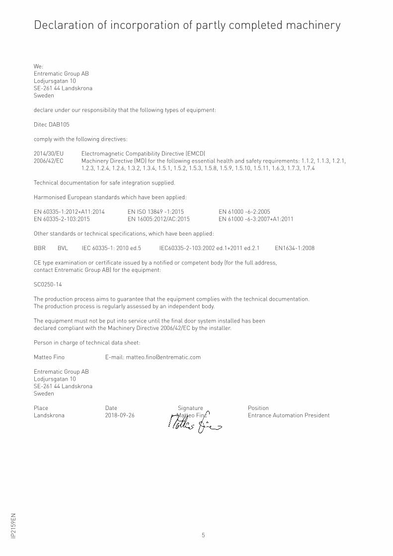
Declaration of incorporation of partly completed machinery
We:
Entrematic Group AB
Lodjursgatan 10
SE-261 44 Landskrona
Sweden
declare under our responsibility that the following types of equipment:
Ditec DAB105
comply with the following directives:
2014/30/EU Electromagnetic Compatibility Directive (EMCD)
2006/42/EC Machinery Directive (MD) for the following essential health and safety requirements: 1.1.2, 1.1.3, 1.2.1,
1.2.3, 1.2.4, 1.2.6, 1.3.2, 1.3.4, 1.5.1, 1.5.2, 1.5.3, 1.5.8, 1.5.9, 1.5.10, 1.5.11, 1.6.3, 1.7.3, 1.7.4
Technical documentation for safe integration supplied.
Harmonised European standards which have been applied:
EN 60335-1:2012+A11:2014 EN ISO 13849 -1:2015 EN 61000 -6-2:2005
EN 60335-2-103:2015 EN 16005:2012/AC:2015 EN 61000 -6-3:2007+A1:2011
Other standards or technical specifications, which have been applied:
BBR BVL IEC 60335-1: 2010 ed.5 IEC60335-2-103:2002 ed.1+2011 ed.2.1 EN1634-1:2008
CE type examination or certificate issued by a notified or competent body (for the full address,
contact Entrematic Group AB) for the equipment:
SC0250-14
The production process aims to guarantee that the equipment complies with the technical documentation.
The production process is regularly assessed by an independent body.
The equipment must not be put into service until the final door system installed has been
declared compliant with the Machinery Directive 2006/42/EC by the installer.
Person in charge of technical data sheet:
Matteo Fino E-mail: [email protected]
Entrematic Group AB
Lodjursgatan 10
SE-261 44 Landskrona
Sweden
Place Date Signature Position
Landskrona 2018-09-26 Matteo Fino Entrance Automation President
g
MaMMMMMMMMMMMMMMMMMMMMMMMaMMMMMMMMMMMMMMMMMM tttttttttttttttttttttttttttttttttttttttttttttttttttttttttttttttttttttttttttttttttttttttttteo Finnooooooooooooooooooooooooooo
6 IP2
15
9E
N
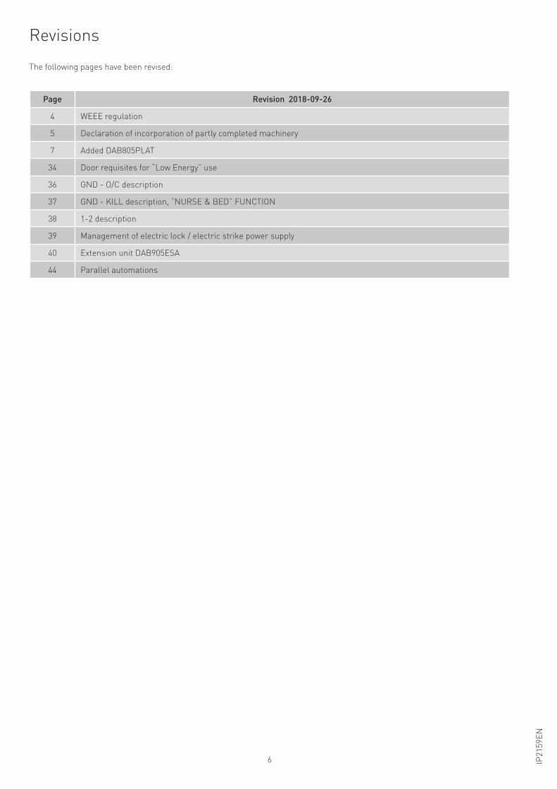
Revisions
The following pages have been revised:
Page Revision 2018-09-26
4 WEEE regulation
5 Declaration of incorporation of partly completed machinery
7 Added DAB805PLAT
34 Door requisites for “Low Energy” use
36 GND - O/C description
37 GND - KILL description, “NURSE & BED” FUNCTION
38 1-2 description
39 Management of electric lock / electric strike power supply
40 Extension unit DAB905ESA
44 Parallel automations
7IP2
15
9E
N
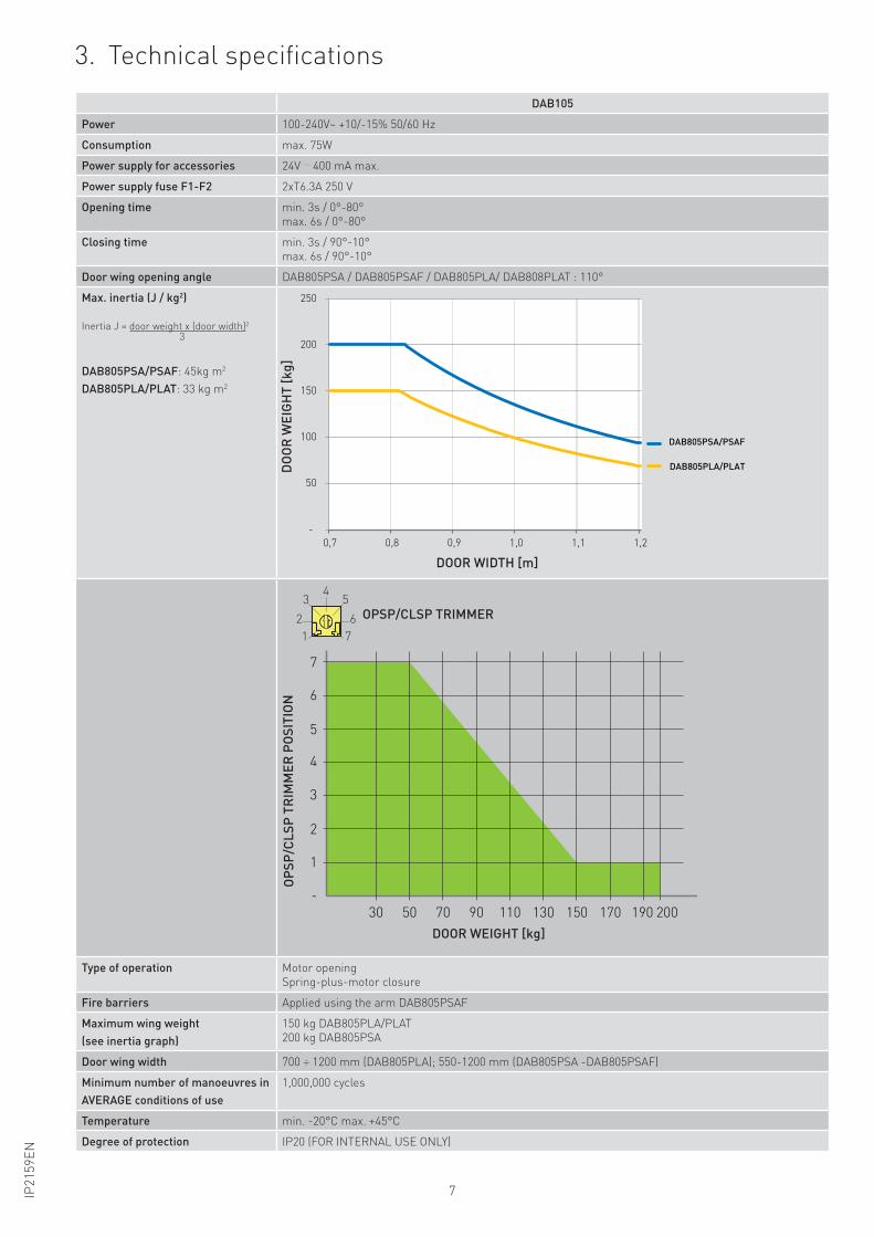
3. Technical specifications
DAB105
Power 100-240V~ +10/-15% 50/60 Hz
Consumption max. 75W
Power supply for accessories 24V 400 mA max.
Power supply fuse F1-F2 2xT6.3A 250 V
Opening time min. 3s / 0°-80°
max. 6s / 0°-80°
Closing time min. 3s / 90°-10°
max. 6s / 90°-10°
Door wing opening angle DAB805PSA / DAB805PSAF / DAB805PLA/ DAB808PLAT : 110°
Max. inertia (J / kg2)
Inertia J = door weight x (door width)2
3
DAB805PSA/PSAF: 45kg m2
DAB805PLA/PLAT: 33 kg m2
-
50
100
150
200
250
0,7 0,8 0,9 1,0 1,1 1,2
DO
OR
WE
IGH
T [
kg
]
DOOR WIDTH [m]
DAB805PSA/PSAF
DAB805PLA/PLAT
-
1
30 50 70 90 110 130 150 170 190 200
2
3
4
5
6
7
OP
SP
/CL
SP
TR
IMM
ER
PO
SIT
ION
DOOR WEIGHT [kg]
OPSP/CLSP TRIMMER
7
45
62
3
1
Type of operation Motor opening
Spring-plus-motor closure
Fire barriers Applied using the arm DAB805PSAF
Maximum wing weight
(see inertia graph)
150 kg DAB805PLA/PLAT
200 kg DAB805PSA
Door wing width 700 ÷ 1200 mm (DAB805PLA); 550-1200 mm (DAB805PSA -DAB805PSAF)
Minimum number of manoeuvres in
AVERAGE conditions of use
1,000,000 cycles
Temperature min. -20°C max. +45°C
Degree of protection IP20 (FOR INTERNAL USE ONLY)
DO
OR
WE
IGH
T [
kg
]
DOOR WIDTH [m]
DOOR WEIGHT [kg]
OP
SP
/CL
SP
TR
IMM
ER
PO
SIT
ION
OPSP/CLSP TRIMMER
8 IP2
15
9E
N
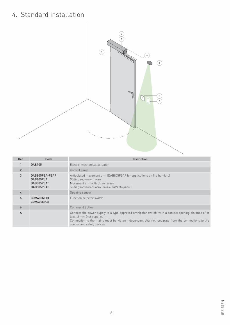
4. Standard installation
Ref. Code Description
1 DAB105 Electro-mechanical actuator
2 Control panel
3 DAB805PSA-PSAF
DAB805PLA
DAB805PLAT
DAB805PLAB
Articulated movement arm (DAB805PSAF for applications on fire barriers)
Sliding movement arm
Movement arm with three levers
Sliding movement arm (break-out/anti-panic)
4 Opening sensor
5 COM400MHB
COM400MKB
Function selector switch
6 Command button
A Connect the power supply to a type-approved omnipolar switch, with a contact opening distance of at
least 3 mm (not supplied).
Connection to the mains must be via an independent channel, separate from the connections to the
control and safety devices.
5
6
1
2
3
A
4
9IP2
15
9E
N
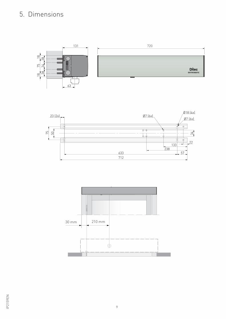
5. Dimensions
75
Ø7 (6x)
50
23 (2x) Ø18 (4x)
57 633
712
133 22
238
34
Ø7 (6x)
63
1313
43
83
8
75
18
18
720
8 1/4"1 11/16"30 mm 210 mm
10 IP2
15
9E
N
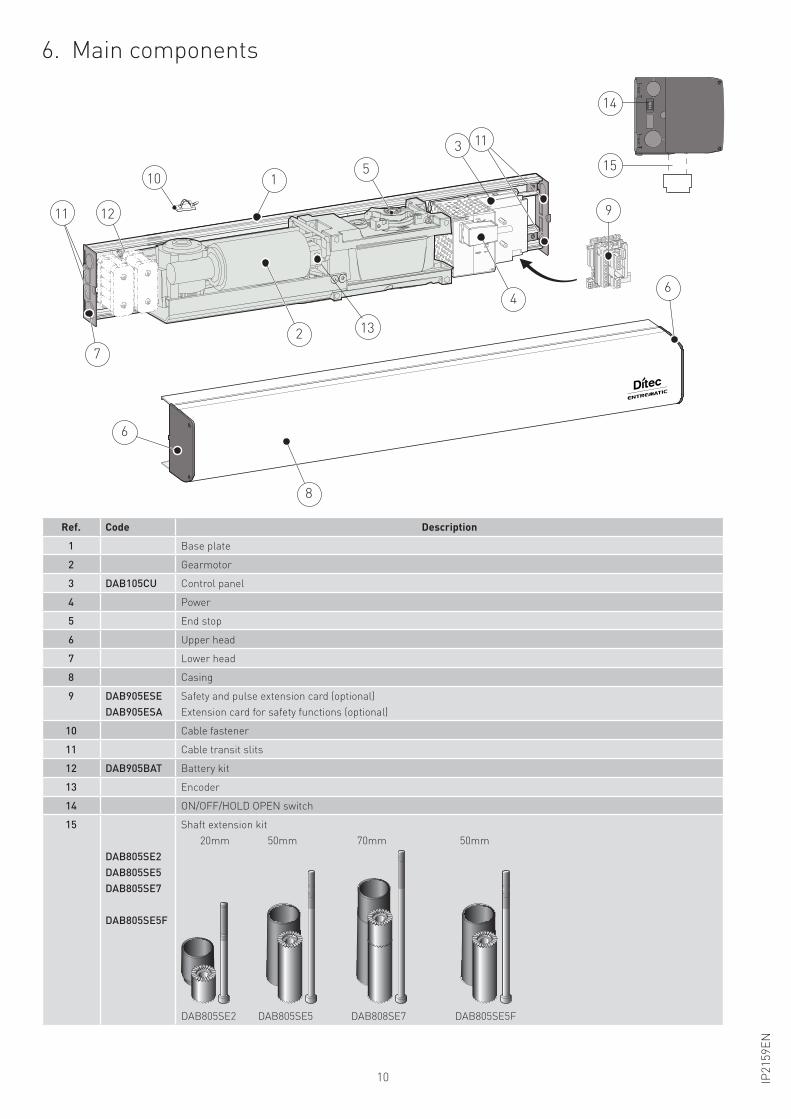
6. Main components
Ref. Code Description
1 Base plate
2 Gearmotor
3 DAB105CU Control panel
4 Power
5 End stop
6 Upper head
7 Lower head
8 Casing
9 DAB905ESE
DAB905ESA
Safety and pulse extension card (optional)
Extension card for safety functions (optional)
10 Cable fastener
11 Cable transit slits
12 DAB905BAT Battery kit
13 Encoder
14 ON/OFF/HOLD OPEN switch
15
DAB805SE2
DAB805SE5
DAB805SE7
DAB805SE5F
Shaft extension kit
20mm 50mm 70mm 50mm
DAB805SE2 DAB805SE5 DAB808SE7 DAB805SE5F
1
113
6
6
8
10
1211
7
9
4
2 13
5
14
15
11IP2
15
9E
N
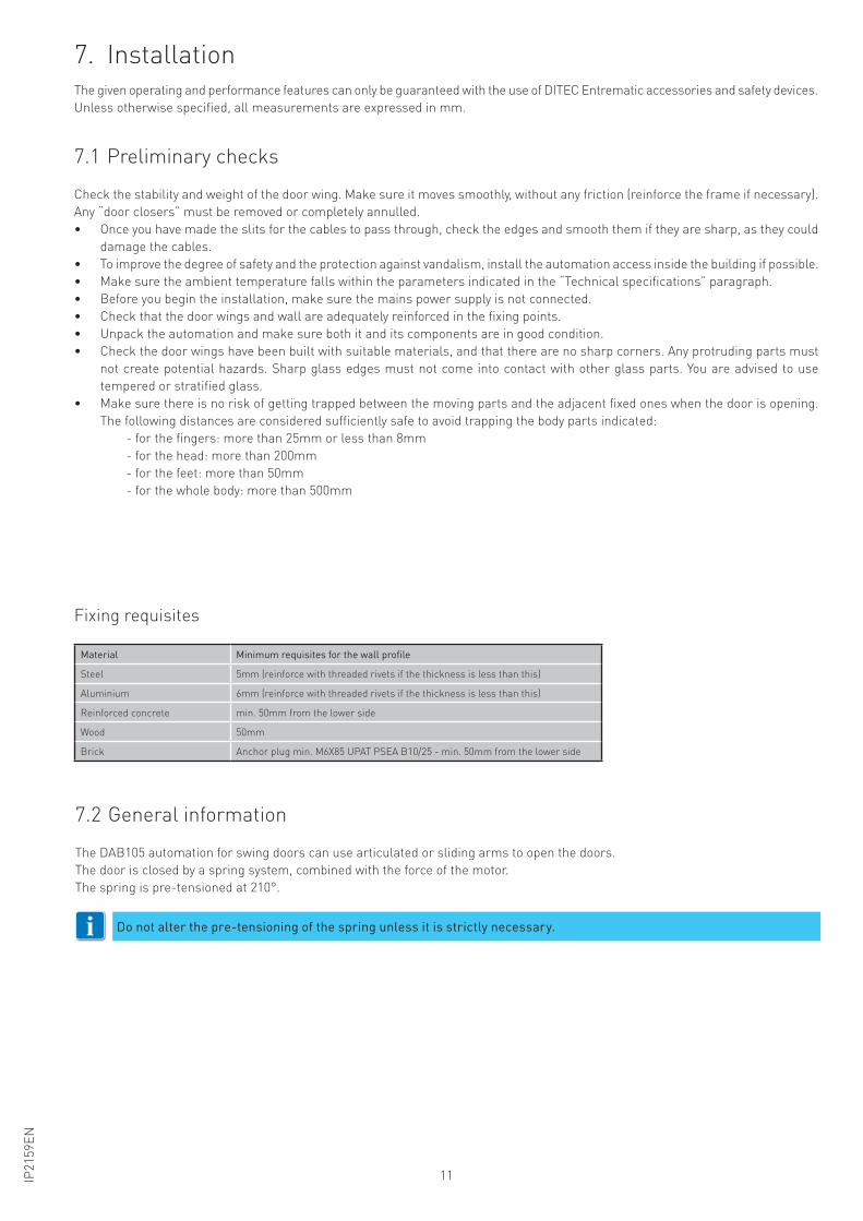
7. Installation
7.1 Preliminary checks
7.2 General information
The given operating and performance features can only be guaranteed with the use of DITEC Entrematic accessories and safety devices.
Unless otherwise specified, all measurements are expressed in mm.
Check the stability and weight of the door wing. Make sure it moves smoothly, without any friction (reinforce the frame if necessary).
Any “door closers” must be removed or completely annulled.
• Once you have made the slits for the cables to pass through, check the edges and smooth them if they are sharp, as they could
damage the cables.
• To improve the degree of safety and the protection against vandalism, install the automation access inside the building if possible.
• Make sure the ambient temperature falls within the parameters indicated in the “Technical specifications” paragraph.
• Before you begin the installation, make sure the mains power supply is not connected.
• Check that the door wings and wall are adequately reinforced in the fixing points.
• Unpack the automation and make sure both it and its components are in good condition.
• Check the door wings have been built with suitable materials, and that there are no sharp corners. Any protruding parts must
not create potential hazards. Sharp glass edges must not come into contact with other glass parts. You are advised to use
tempered or stratified glass.
• Make sure there is no risk of getting trapped between the moving parts and the adjacent fixed ones when the door is opening.
The following distances are considered sufficiently safe to avoid trapping the body parts indicated:
- for the fingers: more than 25mm or less than 8mm
- for the head: more than 200mm
- for the feet: more than 50mm
- for the whole body: more than 500mm
The DAB105 automation for swing doors can use articulated or sliding arms to open the doors.
The door is closed by a spring system, combined with the force of the motor.
The spring is pre-tensioned at 210°.
Do not alter the pre-tensioning of the spring unless it is strictly necessary.i
Fixing requisites
Material Minimum requisites for the wall profile
Steel 5mm (reinforce with threaded rivets if the thickness is less than this)
Aluminium 6mm (reinforce with threaded rivets if the thickness is less than this)
Reinforced concrete min. 50mm from the lower side
Wood 50mm
Brick Anchor plug min. M6X85 UPAT PSEA B10/25 - min. 50mm from the lower side
12 IP2
15
9E
N
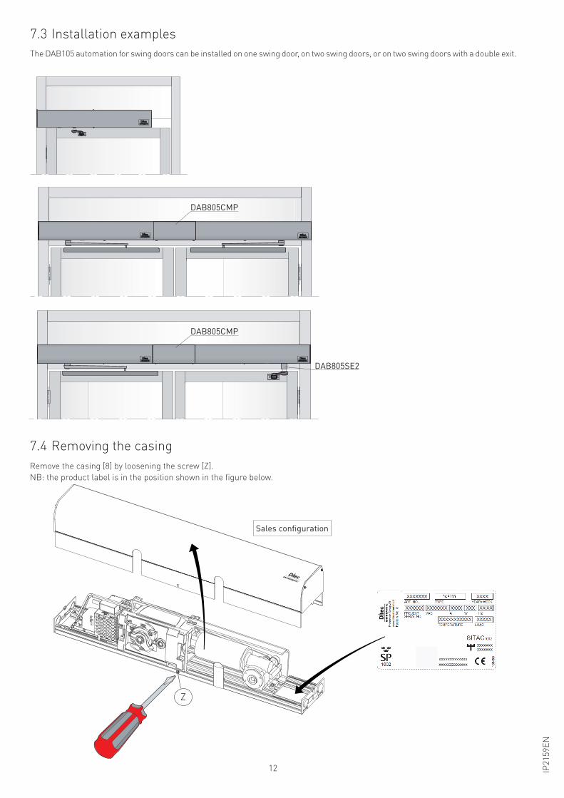
7.4 Removing the casing
Remove the casing [8] by loosening the screw [Z].
NB: the product label is in the position shown in the figure below.
Z
7.3 Installation examples
The DAB105 automation for swing doors can be installed on one swing door, on two swing doors, or on two swing doors with a double exit.
DAB805CMP
DAB805CMP
DAB805SE2
Sales configuration
13IP2
15
9E
N
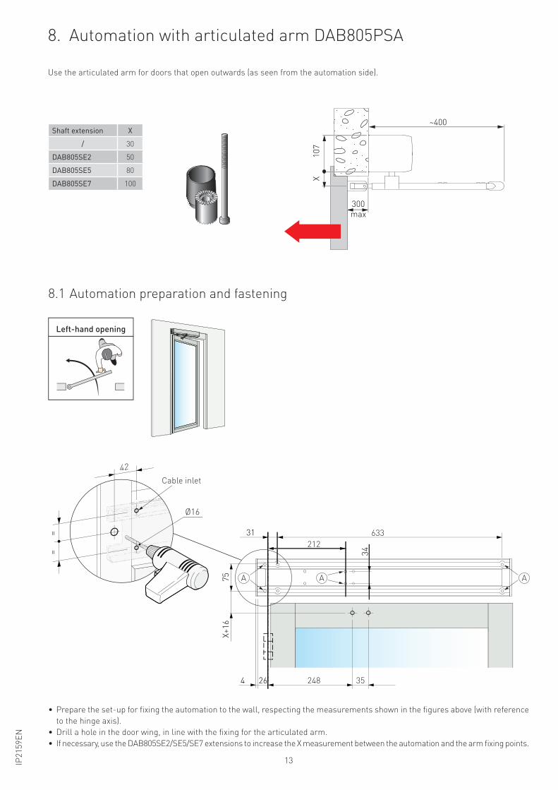
• Prepare the set-up for fixing the automation to the wall, respecting the measurements shown in the figures above (with reference
to the hinge axis).
• Drill a hole in the door wing, in line with the fixing for the articulated arm.
• If necessary, use the DAB805SE2/SE5/SE7 extensions to increase the X measurement between the automation and the arm fixing points.
8. Automation with articulated arm DAB805PSA
8.1 Automation preparation and fastening
Use the articulated arm for doors that open outwards (as seen from the automation side).
Shaft extension X
/ 30
DAB805SE2 50
DAB805SE5 80
DAB805SE7 100
Ø16
==
Ingresso cavo
42
Apertura a sinistra
300
max
~400
10
7X
X+
16
75
34
31
264 248 35
633
212
AA A
Left-hand opening
Cable inlet
14 IP2
15
9E
N
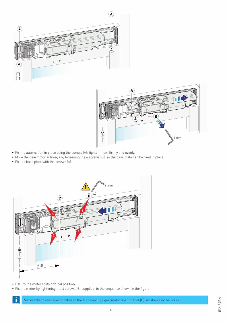
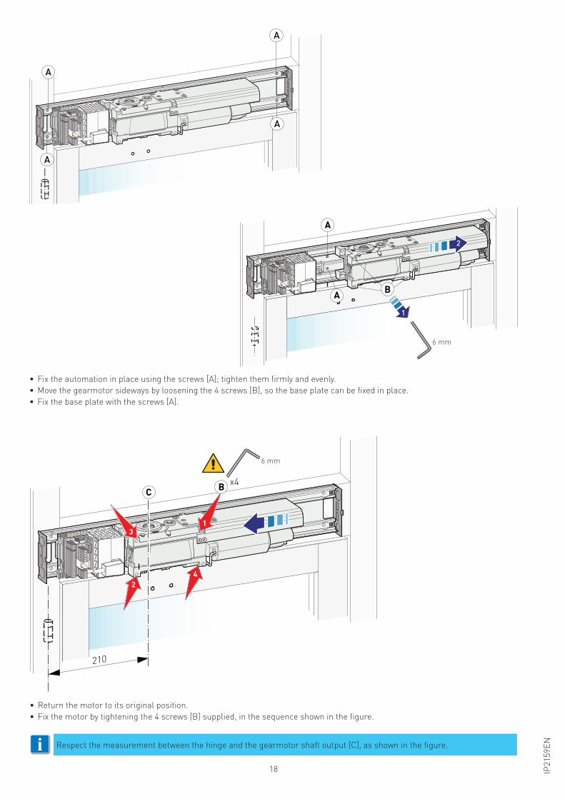
• Fix the automation in place using the screws [A]; tighten them firmly and evenly.
• Move the gearmotor sideways by loosening the 4 screws [B], so the base plate can be fixed in place.
• Fix the base plate with the screws [A].
• Return the motor to its original position.
• Fix the motor by tightening the 4 screws [B] supplied, in the sequence shown in the figure.
Respect the measurement between the hinge and the gearmotor shaft output [C], as shown in the figure.i
210
24
13
B x4C
6 mm
A
A
A
A
1
6 mm
2
A
A B
15IP2
15
9E
N
Apertura a destra
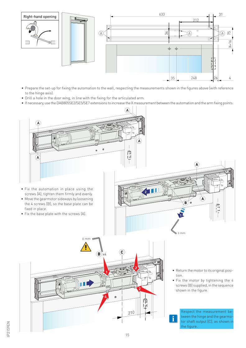
• Fix the automation in place using the
screws [A]; tighten them firmly and evenly.
• Move the gearmotor sideways by loosening
the 4 screws [B], so the base plate can be
fixed in place.
• Fix the base plate with the screws [A].
• Return the motor to its original posi-
tion.
• Fix the motor by tightening the 4
screws [B] supplied, in the sequence
shown in the figure.
Respect the measurement be-
tween the hinge and the gearmo-
tor shaft output [C], as shown in
the figure.
i
Right-hand opening
A
A
A
A
B
A
A
1
2
6 mm
210
13
2
4
CB x4
6 mm
• Prepare the set-up for fixing the automation to the wall, respecting the measurements shown in the figures above (with reference
to the hinge axis).
• Drill a hole in the door wing, in line with the fixing for the articulated arm.
• If necessary, use the DAB805SE2/SE5/SE7 extensions to increase the X measurement between the automation and the arm fixing points.
X+
16
75
34
31
26 424835
633
212
A AA
16 IP2
15
9E
N
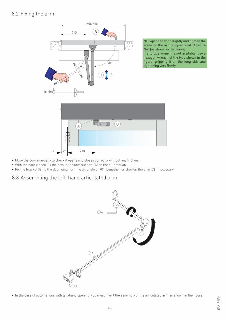
• Move the door manually to check it opens and closes correctly, without any friction.
• With the door closed, fix the arm to the arm support [A] on the automation.
• Fix the bracket [B] to the door wing, forming an angle of 90°. Lengthen or shorten the arm [C] if necessary.
• In the case of automations with left-hand opening, you must invert the assembly of the articulated arm as shown in the figure.
4
4
4
4
8.3 Assembling the left-hand articulated arm.
8.2 Fixing the arm
AB
210264
NB: open the door slightly and tighten the
screw of the arm support seat [A] at 16
Nm (as shown in the figure).
If a torque wrench is not available, use a
hexagon wrench of the type shown in the
figure, gripping it on the long side and
tightening very firmly.A
C
B
90°
16 Nm
+/-
210
min 550
I I I I I I I I I I I I I I I I I I
17IP2
15
9E
N
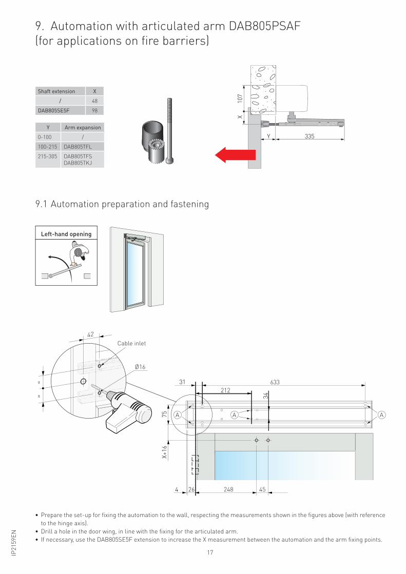
Y Arm expansion
0-100 /
100-215 DAB805TFL
215-305 DAB805TFS
DAB805TKJ
• Prepare the set-up for fixing the automation to the wall, respecting the measurements shown in the figures above (with reference
to the hinge axis).
• Drill a hole in the door wing, in line with the fixing for the articulated arm.
• If necessary, use the DAB805SE5F extension to increase the X measurement between the automation and the arm fixing points.
Shaft extension X
/ 48
DAB805SE5F 98
9. Automation with articulated arm DAB805PSAF
(for applications on fire barriers)
9.1 Automation preparation and fastening
X+
16
75
34
31
264 248 45
633
212
AA A
Y 335
10
7X
Ø16
==
Ingresso cavo
42
Apertura a sinistraLeft-hand opening
Cable inlet
18 IP2
15
9E
N
• Fix the automation in place using the screws [A]; tighten them firmly and evenly.
• Move the gearmotor sideways by loosening the 4 screws [B], so the base plate can be fixed in place.
• Fix the base plate with the screws [A].
• Return the motor to its original position.
• Fix the motor by tightening the 4 screws [B] supplied, in the sequence shown in the figure.
Respect the measurement between the hinge and the gearmotor shaft output [C], as shown in the figure.i
210
24
13
B x4C
6 mm
A
A
A
A
1
6 mm
2
A
A B

19IP2
15
9E
N
Apertura a destra
• Fix the automation in place using the
screws [A]; tighten them firmly and evenly.
• Move the gearmotor sideways by loosening
the 4 screws [B], so the base plate can be
fixed in place.
• Fix the base plate with the screws [A].
• Return the motor to its original posi-
tion.
• Fix the motor by tightening the 4
screws [B] supplied, in the sequence
shown in the figure.
Respect the measurement be-
tween the hinge and the gearmo-
tor shaft output [C], as shown in
the figure.
i
Right-hand opening
A
A
A
A
B
A
A
1
2
6 mm
210
13
2
4
CB x4
6 mm
• Prepare the set-up for fixing the automation to the wall, respecting the measurements shown in the figures above (with reference
to the hinge axis).
• Drill a hole in the door wing, in line with the fixing for the articulated arm.
• If necessary, use the DAB805SE5F extension to increase the X measurement between the automation and the arm fixing points.
X+
16
75
34
31
26 424845
633
212
A AA
20 IP2
15
9E
N
A C
B
I I I I I I I I I I I I I I I I I I
25 Nm
A
210
min 550
90°
+/- DAB805TFL
Kit prolungamento braccio
DAB805TFS
DAB805TKJ
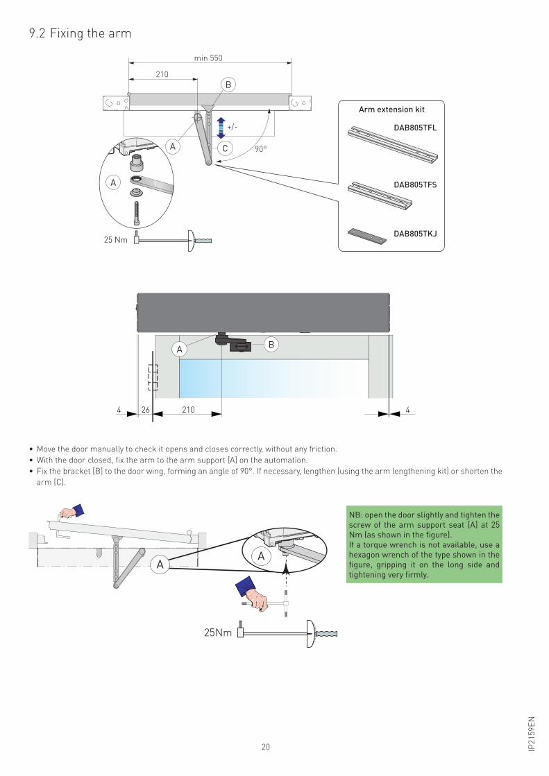
9.2 Fixing the arm
• Move the door manually to check it opens and closes correctly, without any friction.
• With the door closed, fix the arm to the arm support [A] on the automation.
• Fix the bracket [B] to the door wing, forming an angle of 90°. If necessary, lengthen (using the arm lengthening kit) or shorten the
arm [C].
I I I I I I I I I I I I I I I I I
25Nm
AA
NB: open the door slightly and tighten the
screw of the arm support seat [A] at 25
Nm (as shown in the figure).
If a torque wrench is not available, use a
hexagon wrench of the type shown in the
figure, gripping it on the long side and
tightening very firmly.
AB
21026 44
Arm extension kit
21IP2
15
9E
N
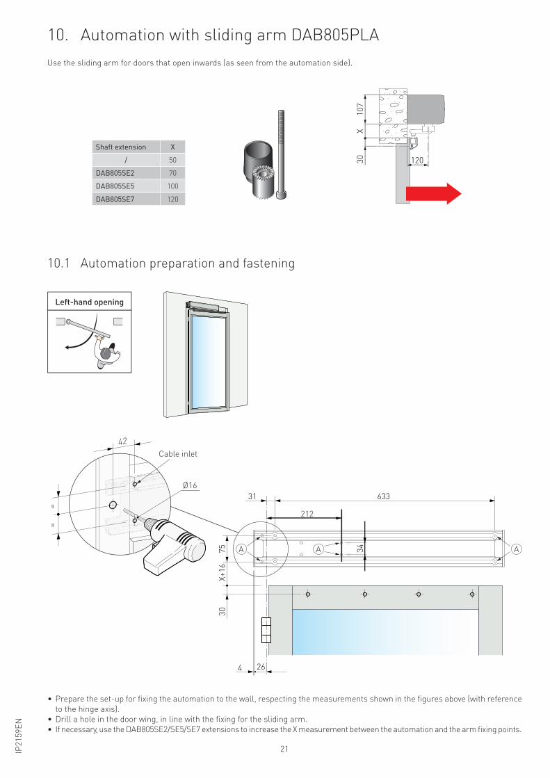
10. Automation with sliding arm DAB805PLA
Use the sliding arm for doors that open inwards (as seen from the automation side).
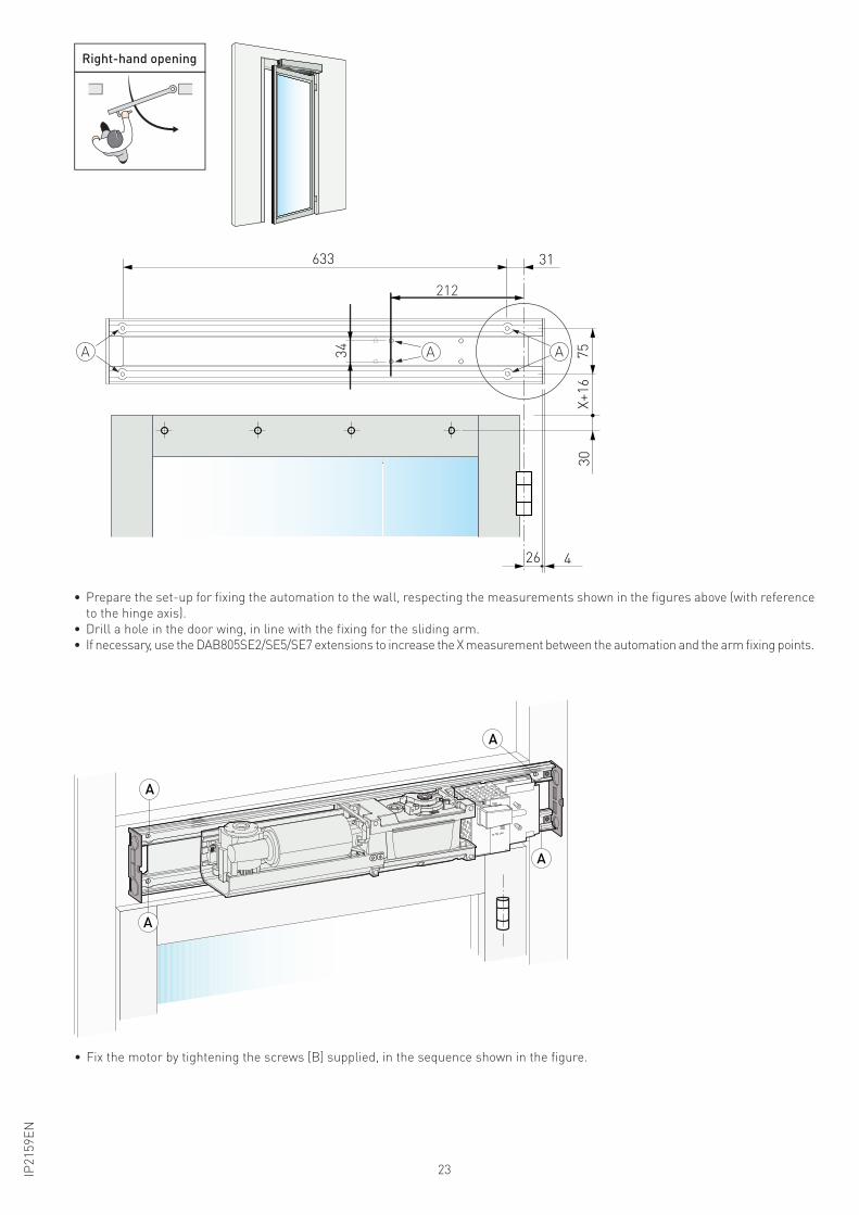
• Prepare the set-up for fixing the automation to the wall, respecting the measurements shown in the figures above (with reference
to the hinge axis).
• Drill a hole in the door wing, in line with the fixing for the sliding arm.
• If necessary, use the DAB805SE2/SE5/SE7 extensions to increase the X measurement between the automation and the arm fixing points.
10.1 Automation preparation and fastening
Shaft extension X
/ 50
DAB805SE2 70
DAB805SE5 100
DAB805SE7 120
30 120
10
7X
X+
16
75
30
31 633
264
34 AA
212
A
Apertura a sinistra
Ø16
==
Ingresso cavo
42
Left-hand opening
Cable inlet
22 IP2
15
9E
N
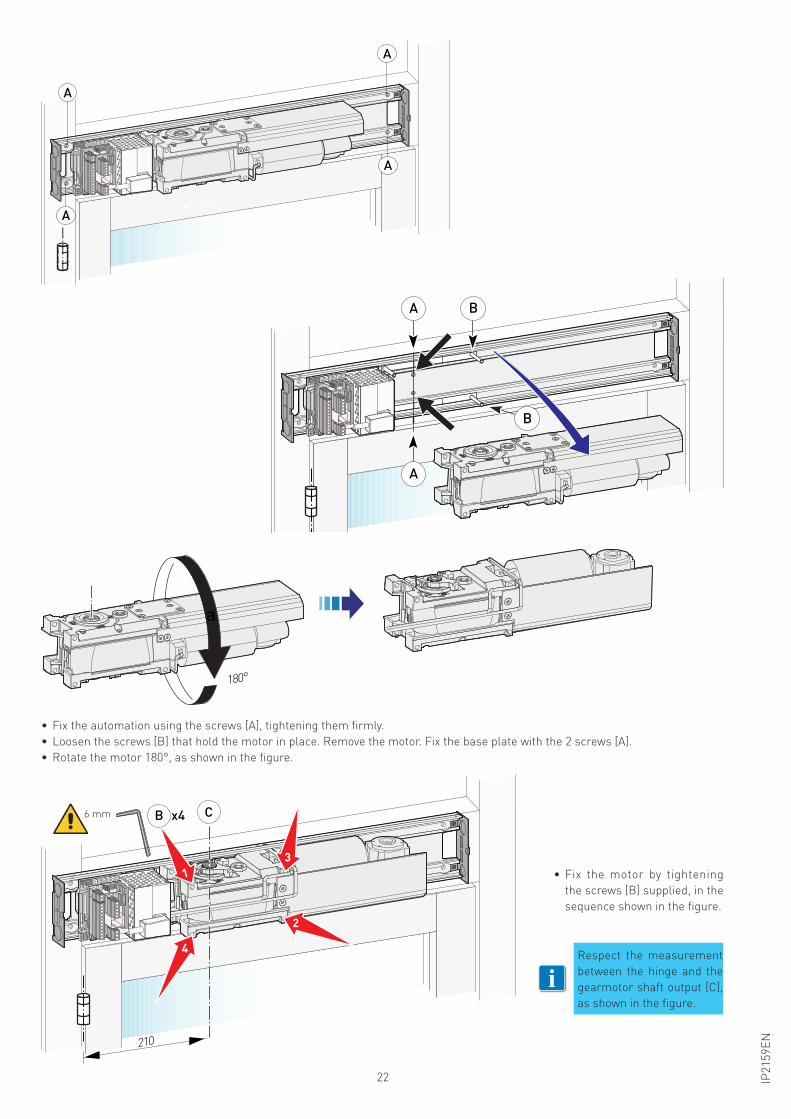
• Fix the automation using the screws [A], tightening them firmly.
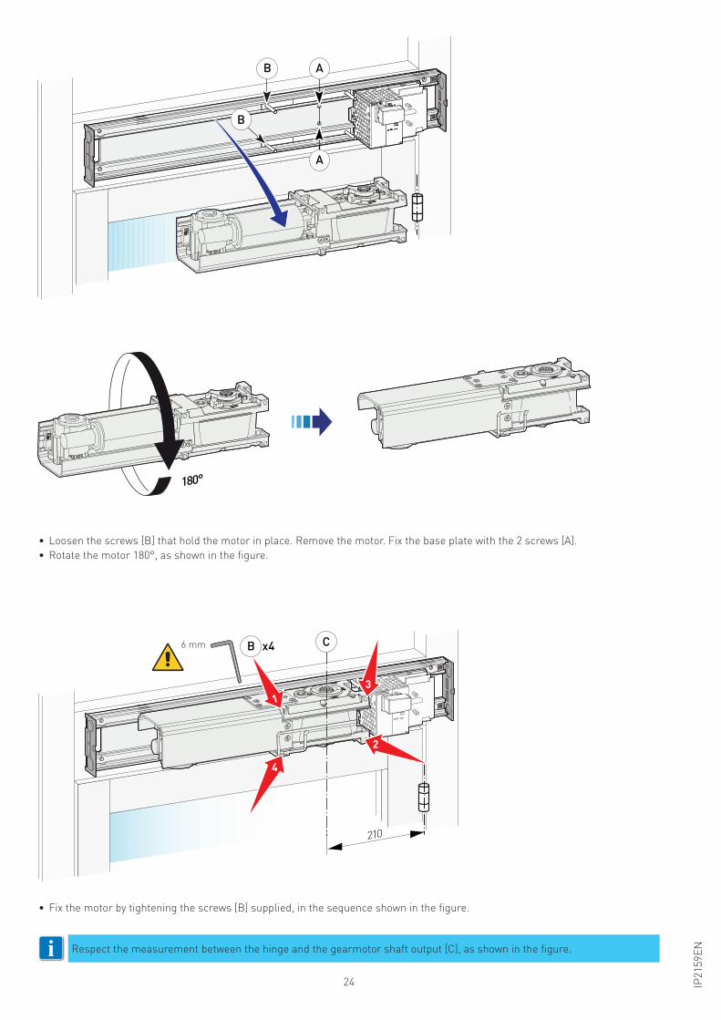
• Loosen the screws [B] that hold the motor in place. Remove the motor. Fix the base plate with the 2 screws [A].
• Rotate the motor 180°, as shown in the figure.
A
A
A
A
A B
A
B
180°
a
210
6 mm C
13
4
2
B x4
• Fix the motor by tightening
the screws [B] supplied, in the
sequence shown in the figure.
Respect the measurement
between the hinge and the
gearmotor shaft output [C],
as shown in the figure.
i
23IP2
15
9E
N
Apertura a destra
• Fix the motor by tightening the screws [B] supplied, in the sequence shown in the figure.
A
A
A
A
• Prepare the set-up for fixing the automation to the wall, respecting the measurements shown in the figures above (with reference
to the hinge axis).
• Drill a hole in the door wing, in line with the fixing for the sliding arm.
• If necessary, use the DAB805SE2/SE5/SE7 extensions to increase the X measurement between the automation and the arm fixing points.
Right-hand opening
X+
16
75
30
31633
26 4
34
212
AA A
24 IP2
15
9E
N
• Loosen the screws [B] that hold the motor in place. Remove the motor. Fix the base plate with the 2 screws [A].
• Rotate the motor 180°, as shown in the figure.
• Fix the motor by tightening the screws [B] supplied, in the sequence shown in the figure.
Respect the measurement between the hinge and the gearmotor shaft output [C], as shown in the figure.i
A
A
B
B
180°
210
C
13
4
2
B x46 mm
25IP2
15
9E
N
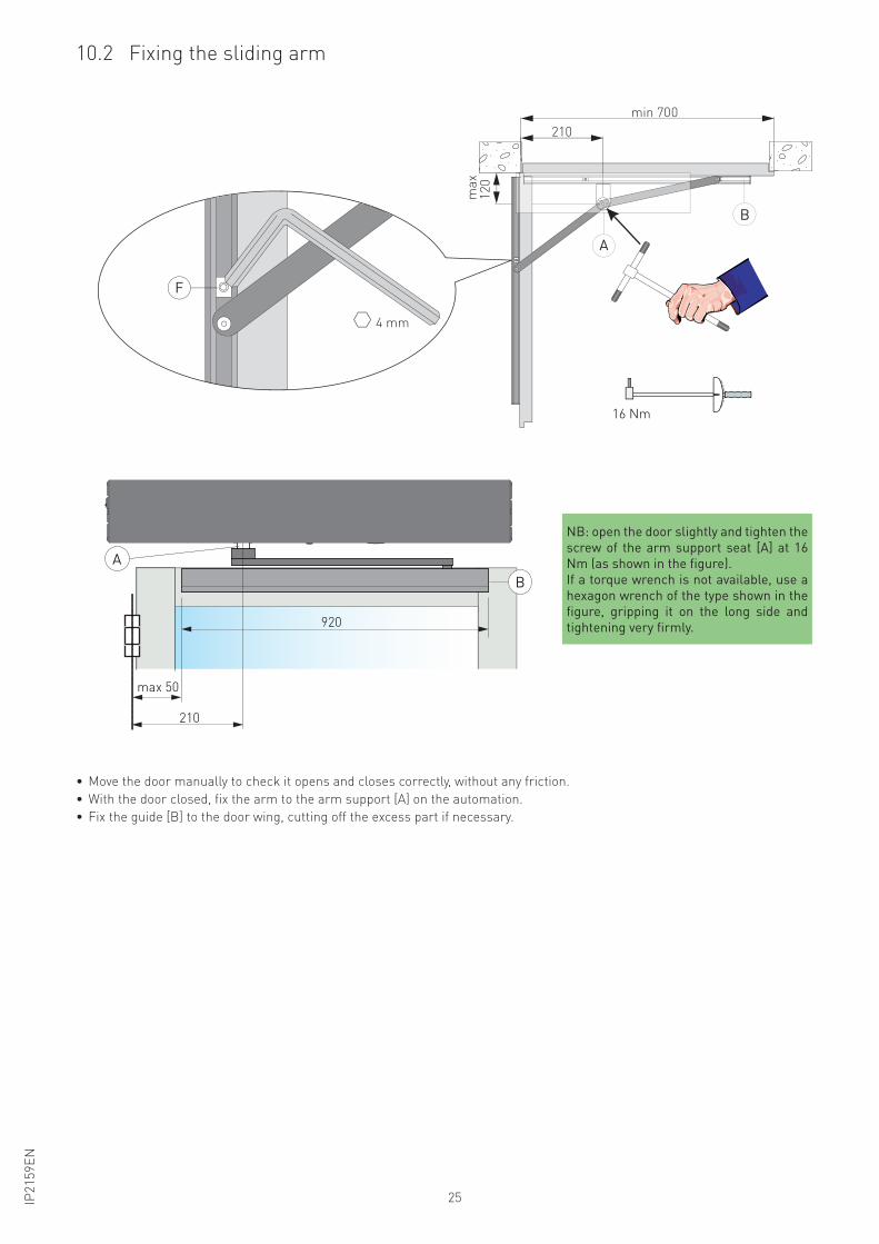
• Move the door manually to check it opens and closes correctly, without any friction.
• With the door closed, fix the arm to the arm support [A] on the automation.
• Fix the guide [B] to the door wing, cutting off the excess part if necessary.
210
max 50
920
A
B
10.2 Fixing the sliding arm
min 700
ma
x1
20
210
4 mm
A
B
F
I I I I I I I I I I I I I I I I I I
16 Nm
NB: open the door slightly and tighten the
screw of the arm support seat [A] at 16
Nm (as shown in the figure).
If a torque wrench is not available, use a
hexagon wrench of the type shown in the
figure, gripping it on the long side and
tightening very firmly.
26 IP2
15
9E
N
Apertura a sinistra Apertura a destra
A
A
BB
C
BB
180°
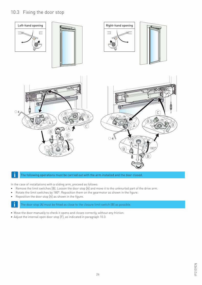
10.3 Fixing the door stop
In the case of installations with a sliding arm, proceed as follows:
• Remove the limit switches [B]. Loosen the door stop [A] and move it to the unknurled part of the drive arm.
• Rotate the limit switches by 180°. Reposition them on the gearmotor as shown in the figure.
• Reposition the door stop [A] as shown in the figure.
• Move the door manually to check it opens and closes correctly, without any friction.
• Adjust the internal open door stop [F], as indicated in paragraph 10.3.
The door stop [A] must be fitted as close to the closure limit switch [B] as possible. i
The following operations must be carried out with the arm installed and the door closed.
A
B
B
C
BB
180°
i
Left-hand opening Right-hand opening
27IP2
15
9E
N
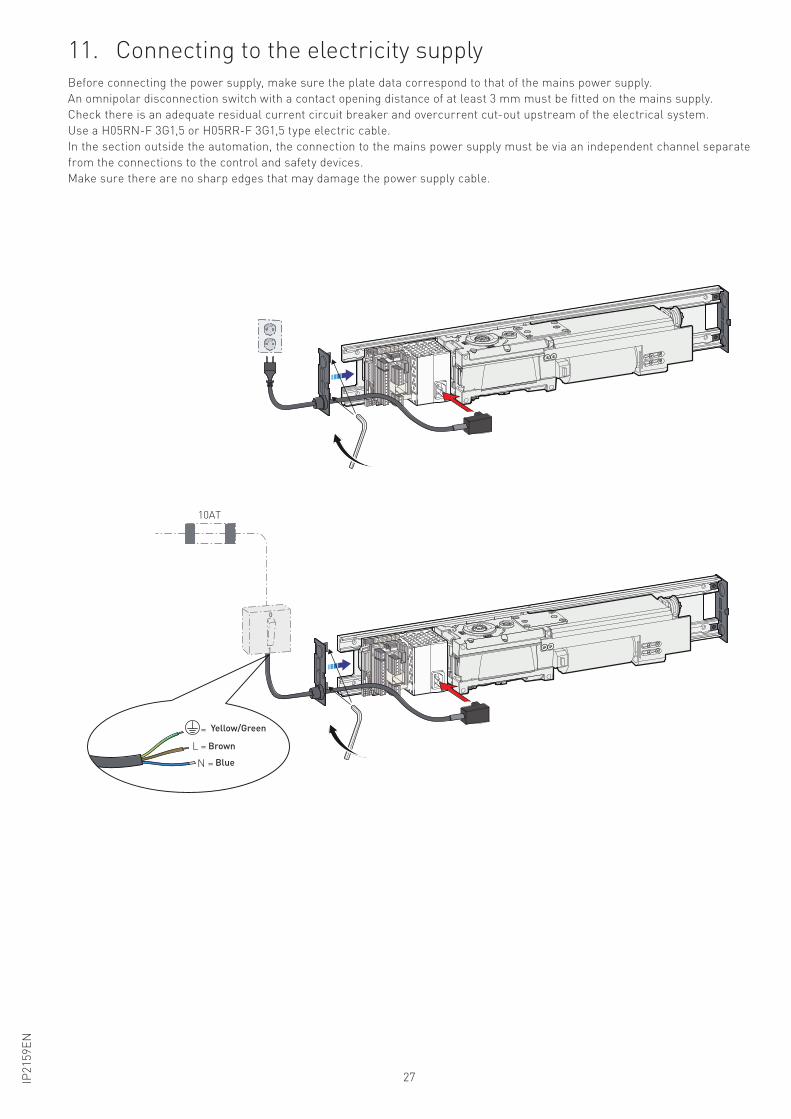
11. Connecting to the electricity supplyBefore connecting the power supply, make sure the plate data correspond to that of the mains power supply.
An omnipolar disconnection switch with a contact opening distance of at least 3 mm must be fitted on the mains supply.
Check there is an adequate residual current circuit breaker and overcurrent cut-out upstream of the electrical system.
Use a H05RN-F 3G1,5 or H05RR-F 3G1,5 type electric cable.
In the section outside the automation, the connection to the mains power supply must be via an independent channel separate
from the connections to the control and safety devices.
Make sure there are no sharp edges that may damage the power supply cable.
0
1
= Yellow/Green
10AT
L = Brown
N = Blue
Yellow/Green
Brown
Blue
28 IP2
15
9E
N
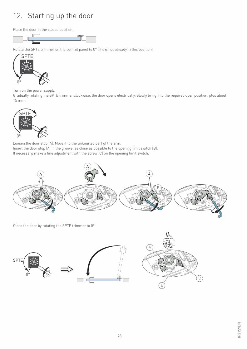
12. Starting up the door
Close the door by rotating the SPTE trimmer to 0°.
Place the door in the closed position.
Rotate the SPTE trimmer on the control panel to 0° (if it is not already in this position).
Turn on the power supply.
Gradually rotating the SPTE trimmer clockwise, the door opens electrically. Slowly bring it to the required open position, plus about
15 mm.
0°
SPTE
0°
SPTE
Loosen the door stop [A]. Move it to the unknurled part of the arm.
Insert the door stop [A] in the groove, as close as possible to the opening limit switch [B].
If necessary, make a fine adjustment with the screw [C] on the opening limit switch.
A
A
A
C
B
0°
SPTE
A
C
B
29IP2
15
9E
N
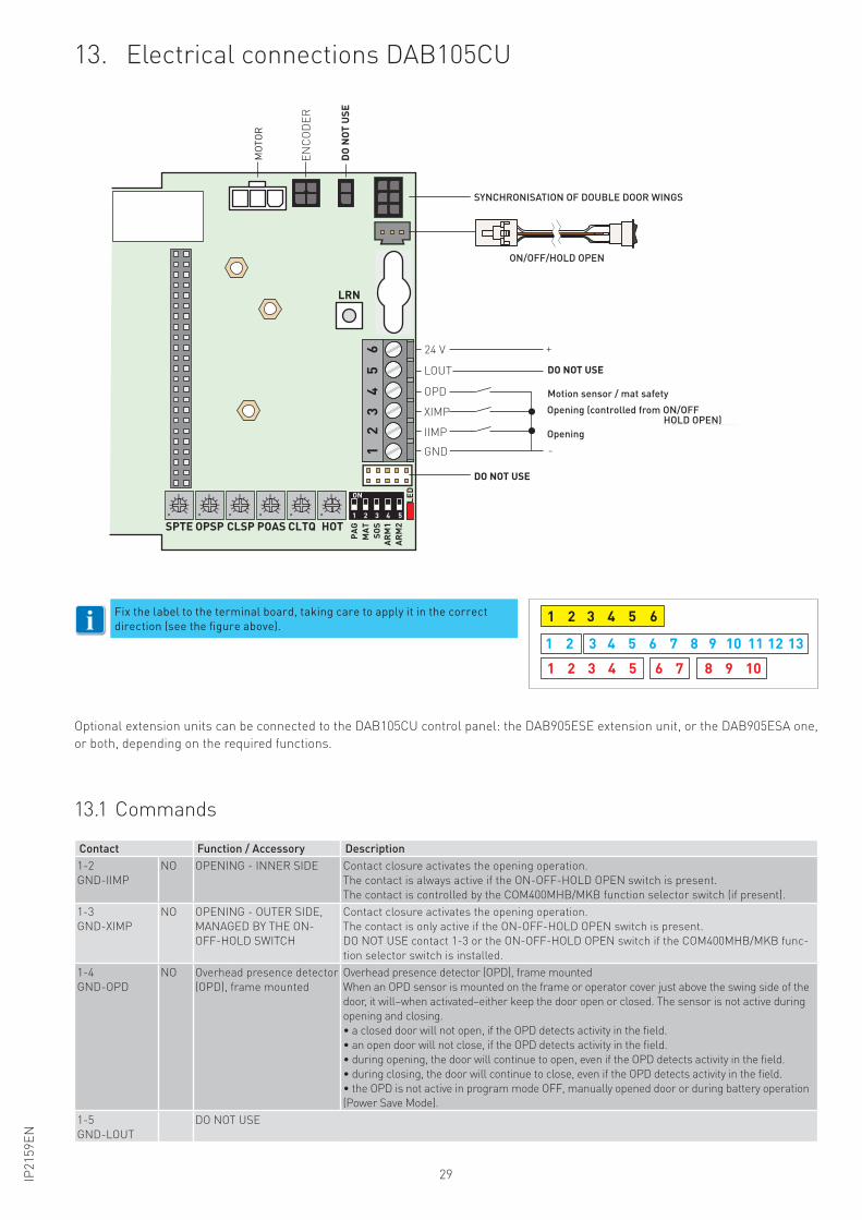
13. Electrical connections DAB105CU
13.1 Commands
Contact Function / Accessory Description
1-2
GND-IIMP
NO OPENING - INNER SIDE Contact closure activates the opening operation.
The contact is always active if the ON-OFF-HOLD OPEN switch is present.
The contact is controlled by the COM400MHB/MKB function selector switch (if present).
1-3
GND-XIMP
NO OPENING - OUTER SIDE,
MANAGED BY THE ON-
OFF-HOLD SWITCH
Contact closure activates the opening operation.
The contact is only active if the ON-OFF-HOLD OPEN switch is present.
DO NOT USE contact 1-3 or the ON-OFF-HOLD OPEN switch if the COM400MHB/MKB func-
tion selector switch is installed.
1-4
GND-OPD
NO Overhead presence detector
(OPD), frame mounted
Overhead presence detector (OPD), frame mounted
When an OPD sensor is mounted on the frame or operator cover just above the swing side of the
door, it will–when activated–either keep the door open or closed. The sensor is not active during
opening and closing.
• a closed door will not open, if the OPD detects activity in the field.
• an open door will not close, if the OPD detects activity in the field.
• during opening, the door will continue to open, even if the OPD detects activity in the field.
• during closing, the door will continue to close, even if the OPD detects activity in the field.
• the OPD is not active in program mode OFF, manually opened door or during battery operation
(Power Save Mode).
1-5
GND-LOUT
DO NOT USE
Fix the label to the terminal board, taking care to apply it in the correct
direction (see the figure above).61 2 3 4 5
6 7 8 9 101 2 3 4 5
1 2 3 4 5 6 7 8 9 10 11 12 13
61
23
45
ON
SPTE OPSP CLSP POAS CLTQ
LRN
HOT
PAG
MAT SO
SAR
M1
ARM
2LE
D
1 2 3 4 5
ON/OFF/HOLD OPEN
EN
CO
DE
R
NO
N U
SAR
E
SINCRONIZZAZIONE ANTE DOPPIE
NON USARE
GND
IIMP
XIMP
OPD
LOUT NON USARE
Apertura (controllata da ON/OFF
HOLD OPEN)
Rilevamento di presenza / pedana a pavimento
Apertura
24 V +
-
MO
TO
RE
i
Optional extension units can be connected to the DAB105CU control panel: the DAB905ESE extension unit, or the DAB905ESA one,
or both, depending on the required functions.
SYNCHRONISATION OF DOUBLE DOOR WINGS
ON/OFF/HOLD OPEN
DO NOT USE
Motion sensor / mat safety
DO NOT USE
Opening (controlled from ON/OFF HOLD OPEN)
Opening
DO
NOT
USE
MO
TO
R
30 IP2
15
9E
N
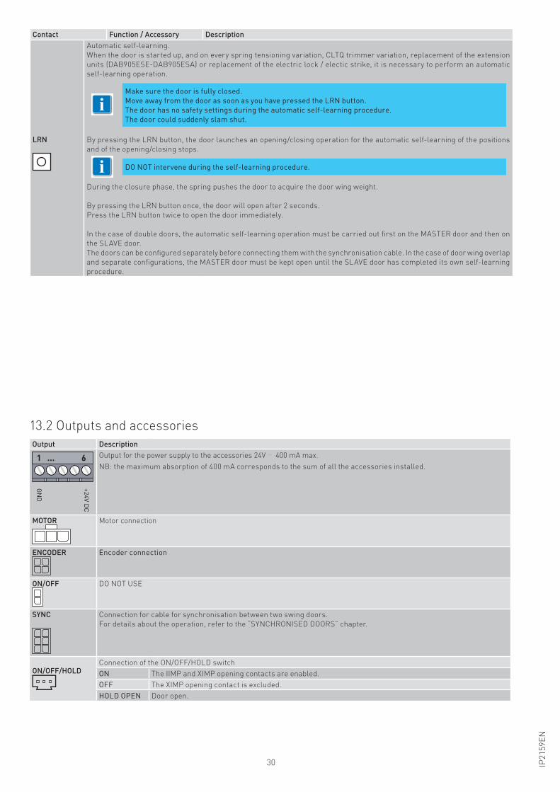
Contact Function / Accessory Description
LRN
Automatic self-learning.
When the door is started up, and on every spring tensioning variation, CLTQ trimmer variation, replacement of the extension
units (DAB905ESE-DAB905ESA) or replacement of the electric lock / electic strike, it is necessary to perform an automatic
self-learning operation.
By pressing the LRN button, the door launches an opening/closing operation for the automatic self-learning of the positions
and of the opening/closing stops.
During the closure phase, the spring pushes the door to acquire the door wing weight.
By pressing the LRN button once, the door will open after 2 seconds.
Press the LRN button twice to open the door immediately.
In the case of double doors, the automatic self-learning operation must be carried out first on the MASTER door and then on
the SLAVE door.
The doors can be configured separately before connecting them with the synchronisation cable. In the case of door wing overlap
and separate configurations, the MASTER door must be kept open until the SLAVE door has completed its own self-learning
procedure.
Make sure the door is fully closed.
Move away from the door as soon as you have pressed the LRN button.
The door has no safety settings during the automatic self-learning procedure.
The door could suddenly slam shut.
DO NOT intervene during the self-learning procedure.i
i
13.2 Outputs and accessories
Output Description
+2
4V
DC
GN
D
1 ... 6 Output for the power supply to the accessories 24V 400 mA max.
NB: the maximum absorption of 400 mA corresponds to the sum of all the accessories installed.
MOTOR Motor connection
ENCODER Encoder connection
ON/OFF DO NOT USE
SYNC Connection for cable for synchronisation between two swing doors.
For details about the operation, refer to the “SYNCHRONISED DOORS” chapter.
ON/OFF/HOLDConnection of the ON/OFF/HOLD switch
ON The IIMP and XIMP opening contacts are enabled.
OFF The XIMP opening contact is excluded.
HOLD OPEN Door open.
31IP2
15
9E
N
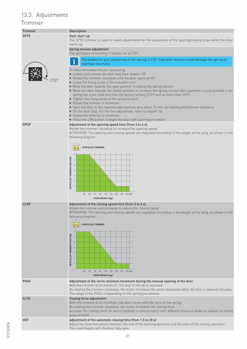
13.3. Adjustments
Trimmer
Trimmer Description
SPTE
210°
Door start-up
The SPTE trimmer is used to make adjustments for the acquisition of the opening/closing stops when the door
starts up.
Spring tension adjustment
The spring pre-tensioning is factory-set at 210°.
To reduce/increase the pre-tensioning:
• Loosen and remove the door stop (see chapter 10)
• Rotate the trimmer clockwise until the door opens at 45°
• Loose the fixing screw of the actuation arm
• Move the door towards the open position to reduce the spring tension
• Move the door towards the closed position to increase the spring tension (this operation is only possible if the
spring has a pre-load less than the factory setting (210°) and no more than 210°).
• Tighten the fixing screw of the actuation arm
• Rotate the trimmer to minimum
• Open the door to the required open position plus about 15 mm, by rotating the trimmer clockwise
• Fix the door stop. For the fine adjustment, refer to chapter 10.
• Rotate the trimmer to minimum
• Press the LRN button to begin the door self-learning procedure
OPSP Adjustment of the opening speed time (from 3 to 6 s).
Rotate the trimmer clockwise to increase the opening speed.
ATTENTION. The opening and closing speeds are regulated according to the weight of the wing, as shown in the
following diagram.
-
1
30 50 70 90 110 130 150 170 190 200
2
3
4
5
6
7
OP
SP
/CL
SP
TR
IMM
ER
PO
SIT
ION
DOOR WEIGHT [kg]
OPSP/CLSP TRIMMER
7
45
62
3
1
CLSP Adjustment of the closing speed time (from 3 to 6 s).
Rotate the trimmer anticlockwise to reduce the closing speed.
ATTENTION. The opening and closing speeds are regulated according to the weight of the wing, as shown in the
following diagram.
-
1
30 50 70 90 110 130 150 170 190 200
2
3
4
5
6
7
OP
SP
/CL
SP
TR
IMM
ER
PO
SIT
ION
DOOR WEIGHT [kg]
OPSP/CLSP TRIMMER
7
45
62
3
1
POAS Adjustment of the servo-assisted movement during the manual opening of the door.
With the trimmer at its minimum, the door is not servo-assisted.
By rotating the trimmer clockwise, the motor increases the servo-assistance when the door is opened manually.
The range of the POAS is depending on the spring pre-tension.
CLTQ Closing force adjustment
With the trimmer at its minimum, the door closes with the force of the spring.
By rotating the trimmer clockwise, the motor increases the closing force.
Increase the closing force on doors installed in environments with different pressure levels or subject to strong
gusts of wind.
HOT Adjustment of the automatic closing time (from 1.5 to 30 s)
Adjust the time that passes between the end of the opening operation and the start of the closing operation.
The count begins with the door fully open.
The maximum pre-tensioning of the spring is 210°. A greater tension could damage the spring or
overheat the motor.i
32 IP2
15
9E
N
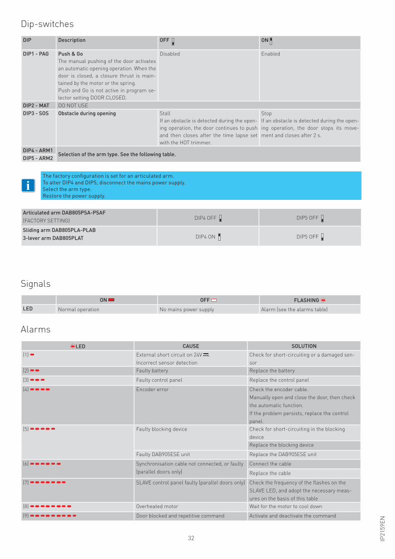
Dip-switches
DIP Description OFF ON
DIP1 - PAG Push & Go
The manual pushing of the door activates
an automatic opening operation. When the
door is closed, a closure thrust is main-
tained by the motor or the spring.
Push and Go is not active in program se-
lector setting DOOR CLOSED.
Disabled Enabled
DIP2 - MAT DO NOT USE
DIP3 - SOS Obstacle during opening Stall
If an obstacle is detected during the open-
ing operation, the door continues to push
and then closes after the time lapse set
with the HOT trimmer.
Stop
If an obstacle is detected during the open-
ing operation, the door stops its move-
ment and closes after 2 s.
DIP4 - ARM1Selection of the arm type. See the following table.
DIP5 - ARM2
Articulated arm DAB805PSA-PSAF
(FACTORY SETTING)DIP4 OFF DIP5 OFF
Sliding arm DAB805PLA-PLAB
3-lever arm DAB805PLAT DIP4 ON DIP5 OFF
The factory configuration is set for an articulated arm.
To alter DIP4 and DIP5, disconnect the mains power supply.
Select the arm type.
Restore the power supply.
Signals
Alarms
ON OFF FLASHING
LED Normal operation No mains power supply Alarm (see the alarms table)
LED CAUSE SOLUTION
(1) External short circuit on 24V .
Incorrect sensor detection
Check for short-circuiting or a damaged sen-
sor
(2) Faulty battery Replace the battery
(3) Faulty control panel Replace the control panel
(4) Encoder error Check the encoder cable.
Manually open and close the door, then check
the automatic function.
If the problem persists, replace the control
panel.
(5) Faulty blocking device Check for short-circuiting in the blocking
device
Replace the blocking device
Faulty DAB905ESE unit Replace the DAB905ESE unit
(6) Synchronisation cable not connected, or faulty
(parallel doors only)
Connect the cable
Replace the cable
(7) SLAVE control panel faulty (parallel doors only) Check the frequency of the flashes on the
SLAVE LED, and adopt the necessary meas-
ures on the basis of this table
(8) Overheated motor Wait for the motor to cool down
(9) Door blocked and repetitive command Activate and deactivate the command
i
33IP2
15
9E
N
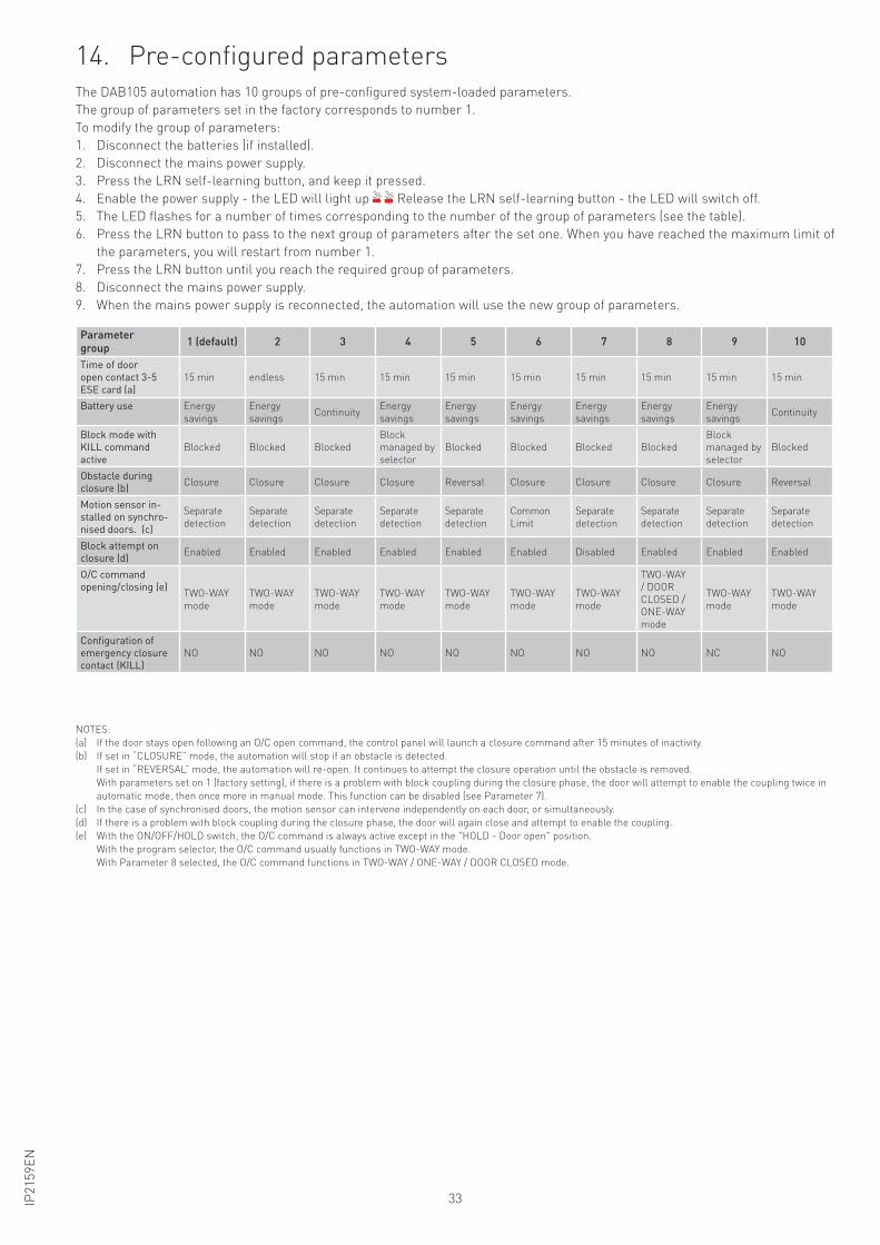
14. Pre-configured parametersThe DAB105 automation has 10 groups of pre-configured system-loaded parameters.
The group of parameters set in the factory corresponds to number 1.
To modify the group of parameters:
1. Disconnect the batteries (if installed).
2. Disconnect the mains power supply.
3. Press the LRN self-learning button, and keep it pressed.
4. Enable the power supply - the LED will light up 3s 3s Release the LRN self-learning button - the LED will switch off.
5. The LED flashes for a number of times corresponding to the number of the group of parameters (see the table).
6. Press the LRN button to pass to the next group of parameters after the set one. When you have reached the maximum limit of
the parameters, you will restart from number 1.
7. Press the LRN button until you reach the required group of parameters.
8. Disconnect the mains power supply.
9. When the mains power supply is reconnected, the automation will use the new group of parameters.
Parameter
group1 (default) 2 3 4 5 6 7 8 9 10
Time of door
open contact 3-5
ESE card (a)
15 min endless 15 min 15 min 15 min 15 min 15 min 15 min 15 min 15 min
Battery use Energy
savings
Energy
savingsContinuity
Energy
savings
Energy
savings
Energy
savings
Energy
savings
Energy
savings
Energy
savingsContinuity
Block mode with
KILL command
active
Blocked Blocked Blocked
Block
managed by
selector
Blocked Blocked Blocked Blocked
Block
managed by
selector
Blocked
Obstacle during
closure (b)Closure Closure Closure Closure Reversal Closure Closure Closure Closure Reversal
Motion sensor in-
stalled on synchro-
nised doors. (c)
Separate
detection
Separate
detection
Separate
detection
Separate
detection
Separate
detection
Common
Limit
Separate
detection
Separate
detection
Separate
detection
Separate
detection
Block attempt on
closure (d)Enabled Enabled Enabled Enabled Enabled Enabled Disabled Enabled Enabled Enabled
O/C command
opening/closing (e)TWO-WAY
mode
TWO-WAY
mode
TWO-WAY
mode
TWO-WAY
mode
TWO-WAY
mode
TWO-WAY
mode
TWO-WAY
mode
TWO-WAY
/ DOOR
CLOSED /
ONE-WAY
mode
TWO-WAY
mode
TWO-WAY
mode
Configuration of
emergency closure
contact (KILL)
NO NO NO NO NO NO NO NO NC NO
NOTES:
(a) If the door stays open following an O/C open command, the control panel will launch a closure command after 15 minutes of inactivity.
(b) If set in “CLOSURE” mode, the automation will stop if an obstacle is detected.
If set in “REVERSAL” mode, the automation will re-open. It continues to attempt the closure operation until the obstacle is removed.
With parameters set on 1 (factory setting), if there is a problem with block coupling during the closure phase, the door will attempt to enable the coupling twice in
automatic mode, then once more in manual mode. This function can be disabled (see Parameter 7).
(c) In the case of synchronised doors, the motion sensor can intervene independently on each door, or simultaneously.
(d) If there is a problem with block coupling during the closure phase, the door will again close and attempt to enable the coupling.
(e) With the ON/OFF/HOLD switch, the O/C command is always active except in the "HOLD - Door open" position.
With the program selector, the O/C command usually functions in TWO-WAY mode.
With Parameter 8 selected, the O/C command functions in TWO-WAY / ONE-WAY / DOOR CLOSED mode.
34 IP2
15
9E
N
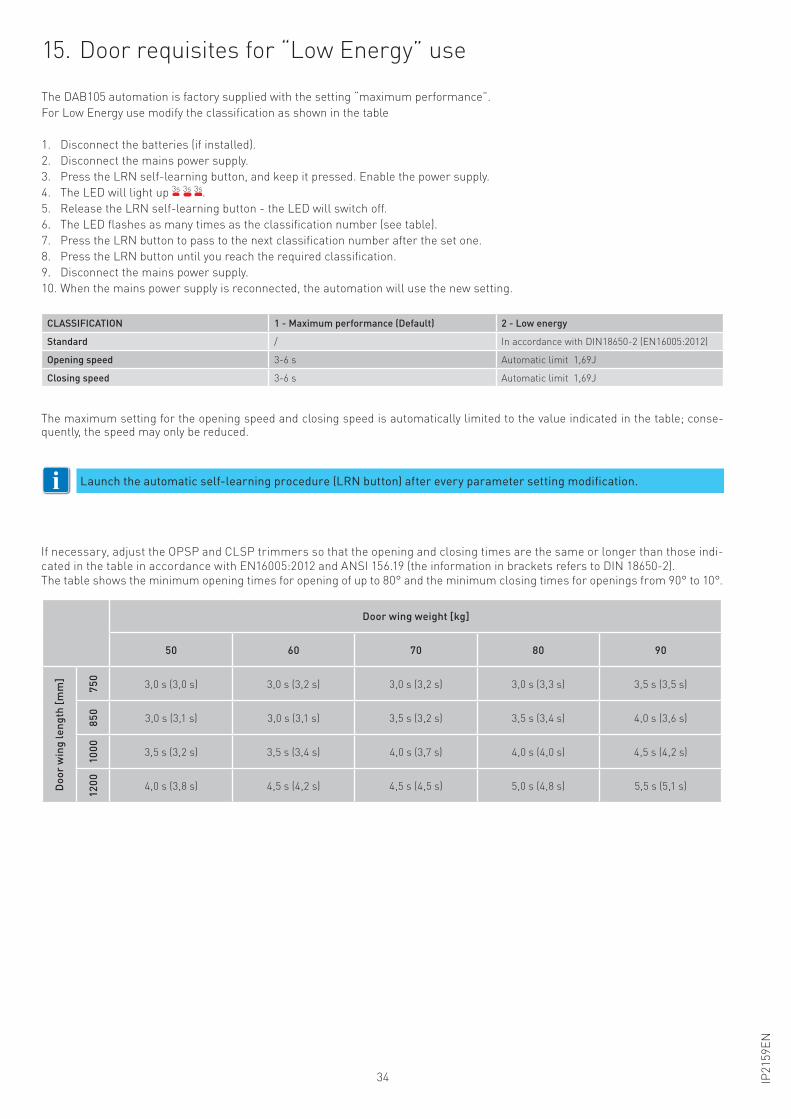
Door wing weight [kg]
50 60 70 80 90
Do
or
win
g l
en
gth
[m
m]
75
0
3,0 s (3,0 s) 3,0 s (3,2 s) 3,0 s (3,2 s) 3,0 s (3,3 s) 3,5 s (3,5 s)
85
0
3,0 s (3,1 s) 3,0 s (3,1 s) 3,5 s (3,2 s) 3,5 s (3,4 s) 4,0 s (3,6 s)
10
00
3,5 s (3,2 s) 3,5 s (3,4 s) 4,0 s (3,7 s) 4,0 s (4,0 s) 4,5 s (4,2 s)
12
00
4,0 s (3,8 s) 4,5 s (4,2 s) 4,5 s (4,5 s) 5,0 s (4,8 s) 5,5 s (5,1 s)
If necessary, adjust the OPSP and CLSP trimmers so that the opening and closing times are the same or longer than those indi-
cated in the table in accordance with EN16005:2012 and ANSI 156.19 (the information in brackets refers to DIN 18650-2).
The table shows the minimum opening times for opening of up to 80° and the minimum closing times for openings from 90° to 10°.
15. Door requisites for “Low Energy” use
The DAB105 automation is factory supplied with the setting “maximum performance”.
For Low Energy use modify the classification as shown in the table
1. Disconnect the batteries (if installed).
2. Disconnect the mains power supply.
3. Press the LRN self-learning button, and keep it pressed. Enable the power supply.
4. The LED will light up 3s 3s 3s.
5. Release the LRN self-learning button - the LED will switch off.
6. The LED flashes as many times as the classification number (see table).
7. Press the LRN button to pass to the next classification number after the set one.
8. Press the LRN button until you reach the required classification.
9. Disconnect the mains power supply.
10. When the mains power supply is reconnected, the automation will use the new setting.
CLASSIFICATION 1 - Maximum performance (Default) 2 - Low energy
Standard / In accordance with DIN18650-2 (EN16005:2012)
Opening speed 3-6 s Automatic limit 1,69J
Closing speed 3-6 s Automatic limit 1,69J
Launch the automatic self-learning procedure (LRN button) after every parameter setting modification.i
The maximum setting for the opening speed and closing speed is automatically limited to the value indicated in the table; conse-quently, the speed may only be reduced.
35IP2
15
9E
N
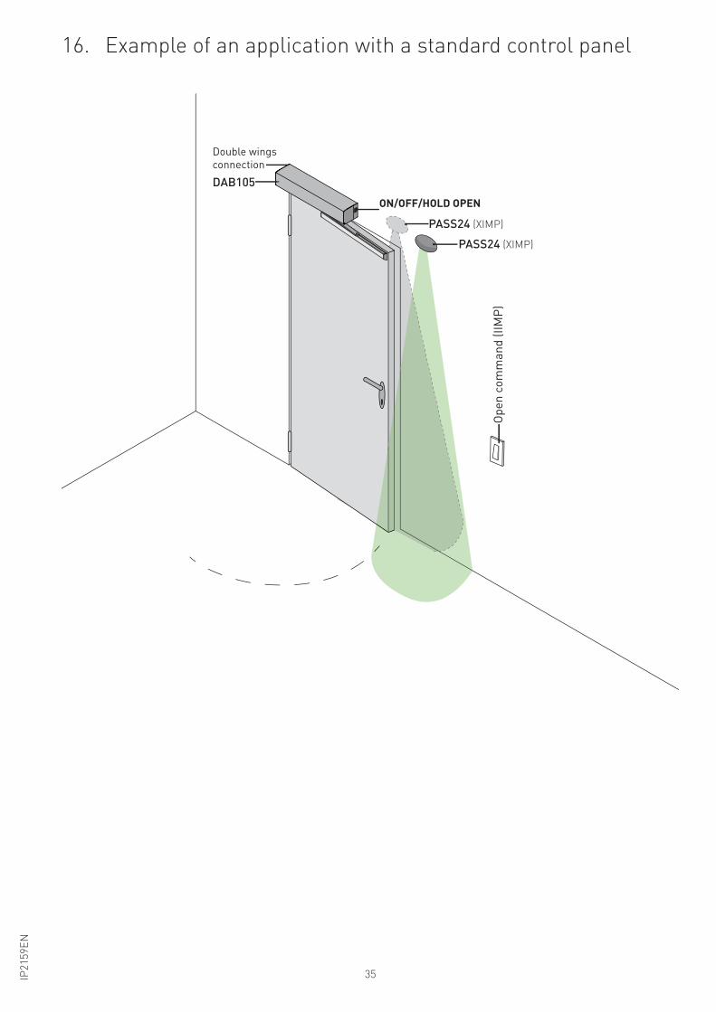
16. Example of an application with a standard control panel
PASS24 (XIMP)
ON/OFF/HOLD OPEN
PASS24 (XIMP)
DAB105
Double wings
connection
Op
en
co
mm
an
d (
IIM
P)
ON/OFF/HOLD OPEN
36 IP2
15
9E
N
DAB905ESA
DAB905ESE
Torx T10
Lo
ng
pin
use
d f
or
2 E
xte
nsio
n U
nit
Sh
ort
pin
u
se
d f
or
1 E
xte
nsio
n U
nit
on
ly
5 mm nut driver
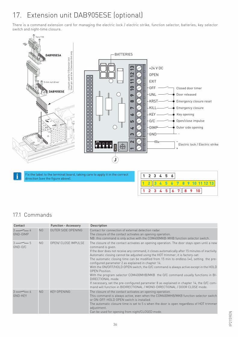
17. Extension unit DAB905ESE (optional)There is a command extension card for managing the electric lock / electric strike, function selector, batteries, key selector
switch and night-time closure.
17.1 Commands
Contact Function - Accessory Description
3 4
GND-OIMP
NO OUTER SIDE OPENING Contact for connection of external detection radar.
The closure of the contact activates an opening operation.
NB: this command is only active with the COM400MKB-MHB function selector switch.
3 5
GND-O/C
NO OPEN/ CLOSE IMPULSE The closure of the contact activates an opening operation. The door stays open until a new
command is given.
If the door does not receive any command, it closes automatically after 15 minutes of inactivity.
Automatic closing cannot be adjusted using the HOT trimmer; it is factory-set.
The automatic closing time can be modified from 15 min to endless (∞), setting the pre-
configured parameter 2 as explained in chapter 14.
With the ON/OFF/HOLD OPEN switch, the O/C command is always active except in the HOLD
OPEN Position.
With the program selector COM400MHB/MKB the O/C command usually functions in BI-
DIRECTIONAL mode.
If necessary, set the pre-configured parameter 8 as explained in chapter 14, the O/C com-
mand will function in BIDIRECTIONAL / MONO-DIRECTIONAL / DOOR CLOSE mode.
3 6
GND-KEY
NO KEY OPENING The closure of the contact activates an opening operation.
This command is always active, even when the COM400MHB/MKB function selector switch
or ON-OFF-HOLD OPEN switch is installed.
The automatic closure time is set to 5 s when the door is open regardless of HOT trimmer
adjustment.
Can be used for opening from night/CLOSED mode.
61 2 3 4 5
6 7 8 9 101 2 3 4 5
1 2 3 4 5 6 7 8 9 10 11 12 13
Fix the label to the terminal board, taking care to apply it in the correct
direction (see the figure above).
-
–
+1 2 3 4 5
ON
+24 V DC
KILL
KEY
O/C
OIMP
GND
BATTERIE
12
34
56
78
910
1112
13
OPEN
EXIT
OFF
UNL
KRST
Serratura elettrica / Incontro elettrico
Apertura lato esterno
Passo passo
Apertura a chiave
Chiusura di emergenza
Reset chiusura di emergenza
Porta sbloccata
Temporizzatore porta chiusa
J
i
BATTERIES
Closed door timer
Emergency closure reset
Key opening
Door released
Emergency closure
Open/close impulse
Outer side opening
Electric lock / Electric strike
37IP2
15
9E
N
Contact Function - Accessory Description
3 7
GND-KILL
NO EMERGENCY CLOSURE
(FIRE BARRIERS)
The closure of the contact activates an emergency closure operation. This command is ac-tive in every situation, and has priority over every other command. When the contact has reopened (with JUMPER J=ON), the door resumes operating as set by the selector.
WARNING: if an EMERGENCY CLOSURE is activated, all the safety functions are ignored and the door closes. People or objects in the path of the door during the closing operation could suffer serious injury or damage.This function is generally used to cut off a specific area in the case of a fire.
NB: this command can be combined with an emergency button.The output contact can be changed from NO to NC by altering the pre-configured param-eters, as explained in chapter 13.The operation of the block during the emergency closure can be selected from the pre-set parameters explained in chapter 13.A panic bar can be installed in combination with a magnetic block on the fire barrier.In the event of a fire alarm or a power supply failure, the panic bar keeps the closed door blocked. In the case of escape routes, the panic bar can be manually released. Configure the relay contact of the DAB905ESA card, choosing parameter 11, 12 or 13 as explained in chapter 13.
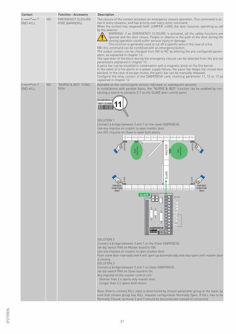
3 7
GND-KILL
NO “NURSE & BED” FUNC-
TION
Available on the control panle version indicated, or subsequent versions.
In installations with parallel doors, the “NURSE & BED” function can be enabled by con-
necting a switch to contacts 3-7 on the SLAVE door control panel.
1118011234566DAB205CU
SOLUTION 1
Connect a bridge between 3 and 7 on the slave DAB905ESE.
Use any impulse on master to open master door.
Use O/C impulse on Slave to open both doors.
SL
AV
EM
AS
TE
R
IIM
P
(MA
ST
ER
)
OIM
P
(MA
ST
ER
)
MA
ST
ER
MA
ST
ER
SL
AV
E
SL
AV
E
FOR BED
FUNCTION
ONLY
FOR BED
FUNCTION
ONLY
1 2 3 4 5
ON
+24 V DC
KEY
O/C
OIMP
GND
12
34
56
78
910
1112
13
OPEN
EXIT
OFF
UNL
KRST
KILL
DAB905ESE
SLAVE
SOLUTION 2
Connect a bridge between 3 and 7 on the Slave DAB905ESE.
Set dip switch PAG on Master board to ON.
Use any impulse on master to open master door.
Push slave door manually and it will open up automatically and stay open until master door
is closing.
SOLUTION 3
Connect a bridge between 3 and 7 on Slave DAB905ESE.
Set dip switch PAG on Slave board to On.
Any impulse on the master control unit:
- Shorter than 2 s opens only master door.
- Longer than 2 s opens both doors.
Note: How to connect KILL input is determined by chosen parameter group at the slave, be
sure that chosen group has KILL impulse configuration Normally Open. If KILL has to be
Normally Closed, terminal 3 and 7 should be disconnected instead of connected.
38 IP2
15
9E
N
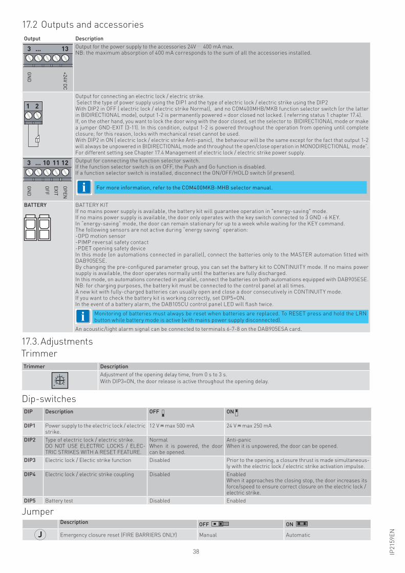
Output Description
+2
4V
DC
GN
D
3 ... 13 Output for the power supply to the accessories 24V 400 mA max. NB: the maximum absorption of 400 mA corresponds to the sum of all the accessories installed.
1 2Output for connecting an electric lock / electric strike. Select the type of power supply using the DIP1 and the type of electric lock / electric strike using the DIP2With DIP2 in OFF ( electric lock / electric strike Normal), and no COM400MHB/MKB function selector switch (or the latter in BIDIRECTIONAL mode), output 1-2 is permanently powered = door closed not locked. ( referring status 1 chapter 17.4).If, on the other hand, you want to lock the door wing with the door closed, set the selector to BIDIRECTIONAL mode or make a jumper GND-EXIT (3-11). In this condition, output 1-2 is powered throughout the operation from opening until complete closure; for this reason, locks with mechanical reset cannot be used. With DIP2 in ON ( electric lock / electric strike Anti-panic), the behaviour will be the same except for the fact that output 1-2 will always be unpowered in BIDIRECTIONAL mode and throughout the open/close operation in MONODIRECTIONAL mode”.For different setting see Chapter 17.4 Management of electric lock / electric strike power supply.
OP
EN
EX
IT
OF
F
GN
D
3 ... 10 11 12 Output for connecting the function selector switch.If the function selector switch is on OFF, the Push and Go function is disabled.If a function selector switch is installed, disconnect the ON/OFF/HOLD switch (if present).
BATTERY BATTERY KITIf no mains power supply is available, the battery kit will guarantee operation in "energy-saving" mode.If no mains power supply is available, the door only operates with the key switch connected to 3 GND -6 KEY. In “energy-saving” mode, the door can remain stationary for up to a week while waiting for the KEY command.The following sensors are not active during “energy saving” operation:-OPD motion sensor-PIMP reversal safety contact -PDET opening safety deviceIn this mode (on automations connected in parallel), connect the batteries only to the MASTER automation fitted with DAB905ESE.By changing the pre-configured parameter group, you can set the battery kit to CONTINUITY mode. If no mains power supply is available, the door operates normally until the batteries are fully discharged.In this mode, on automations connected in parallel, connect the batteries on both automations equipped with DAB905ESE.NB: for charging purposes, the battery kit must be connected to the control panel at all times. A new kit with fully-charged batteries can usually open and close a door consecutively in CONTINUITY mode.If you want to check the battery kit is working correctly, set DIP5=ON.In the event of a battery alarm, the DAB105CU control panel LED will flash twice.
i Monitoring of batteries must always be reset when batteries are replaced. To RESET press and hold the LRN
button while battery mode is active (with mains power supply disconnected).
An acoustic/light alarm signal can be connected to terminals 6-7-8 on the DAB905ESA card.
17.3. Adjustments
17.2 Outputs and accessories
Trimmer
Trimmer Description
Adjustment of the opening delay time, from 0 s to 3 s.
With DIP3=ON, the door release is active throughout the opening delay.
Dip-switchesDIP Description OFF ON
DIP1 Power supply to the electric lock / electric strike.
12 V max 500 mA 24 V max 250 mA
DIP2 Type of electric lock / electric strike.DO NOT USE ELECTRIC LOCKS / ELEC-TRIC STRIKES WITH A RESET FEATURE.
NormalWhen it is powered, the door can be opened.
Anti-panicWhen it is unpowered, the door can be opened.
DIP3 Electric lock / Electic strike function Disabled Prior to the opening, a closure thrust is made simultaneous-ly with the electric lock / electric strike activation impulse.
DIP4 Electric lock / electric strike coupling Disabled EnabledWhen it approaches the closing stop, the door increases its force/speed to ensure correct closure on the electric lock / electric strike.
DIP5 Battery test Disabled Enabled
JumperDescription OFF ON
J Emergency closure reset (FIRE BARRIERS ONLY) Manual Automatic
For more information, refer to the COM400MKB-MHB selector manual.i
39IP2
15
9E
N
17.4 Advanced settings available on the control panel version indicated, or subse-quent versions
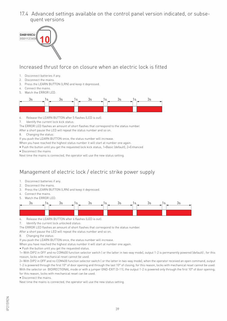
Increased thrust force on closure when an electric lock is fitted
Management of electric lock / electric strike power supply
1. Disconnect batteries if any.
2. Disconnect the mains.
3. Press the LEARN BUTTON (LRN) and keep it depressed.
4. Connect the mains.
5. Watch the ERROR LED.
3s1s3s1s3s1s3s1s3s
6. Release the LEARN BUTTON after 5 flashes (LED is out).
7. Identify the current lock kick status:
The ERROR LED flashes an amount of short flashes that correspond to the status number.
After a short pause the LED will repeat the status number and so on.
8. Changing the status:
If you push the LEARN BUTTON once, the status number will increase.
When you have reached the highest status number it will start at number one again.
• Push the button until you get the requested lock kick status, 1=Basic (default), 2=Enhanced
• Disconnect the mains
Next time the mains is connected, the operator will use the new status setting.
1. Disconnect batteries if any.
2. Disconnect the mains.
3. Press the LEARN BUTTON (LRN) and keep it depressed.
4. Connect the mains.
5. Watch the ERROR LED.
3s1s3s1s3s1s3s1s3s 3s1s
6. Release the LEARN BUTTON after 6 flashes (LED is out).
7. Identify the current lock unlocked status:
The ERROR LED flashes an amount of short flashes that correspond to the status number.
After a short pause the LED will repeat the status number and so on.
8. Changing the status:
If you push the LEARN BUTTON once, the status number will increase.
When you have reached the highest status number it will start at number one again.
• Push the button until you get the requested status.
1= With DIP2 in OFF and no COM400 function selector switch ( or the latter in two-way mode), output 1-2 is permanently powered (default) ; for this
reason, locks with mechanical reset cannot be used.
2= With DIP2 in OFF and no COM400 function selector switch ( or the latter in two-way mode), when the operator received an open command, output
1-2 is powered through the first 10° of door opening and through the last 10° of closing; for this reason, locks with mechanical reset cannot be used.
With the selector on BIDIRECTIONAL mode or with a jumper GND-EXIT (3-11), the output 1-2 is powered only through the first 10° of door opening;
for this reason, locks with mechanical reset can be used.
• Disconnect the mains.
Next time the mains is connected, the operator will use the new status setting.
0501123456DAB105CU
10
40 IP2
15
9E
N
DAB905ESA
DAB905ESE
Torx T10
Lo
ng
pin
use
d f
or
2 E
xte
nsio
n U
nit
Sh
ort
pin
u
se
d f
or
1 E
xte
nsio
n U
nit
on
ly
5 mm nut driver
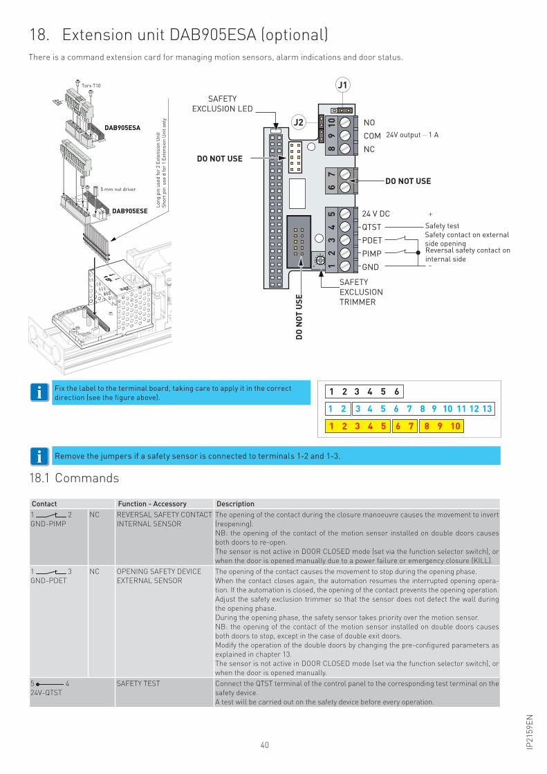
18. Extension unit DAB905ESA (optional)There is a command extension card for managing motion sensors, alarm indications and door status.
Remove the jumpers if a safety sensor is connected to terminals 1-2 and 1-3.
18.1 Commands
Contact Function - Accessory Description
1 2
GND-PIMP
NC REVERSAL SAFETY CONTACT
INTERNAL SENSOR
The opening of the contact during the closure manoeuvre causes the movement to invert
(reopening).
NB: the opening of the contact of the motion sensor installed on double doors causes
both doors to re-open.
The sensor is not active in DOOR CLOSED mode (set via the function selector switch), or
when the door is opened manually due to a power failure or emergency closure (KILL).
1 3
GND-PDET
NC OPENING SAFETY DEVICE
EXTERNAL SENSOR
The opening of the contact causes the movement to stop during the opening phase.
When the contact closes again, the automation resumes the interrupted opening opera-
tion. If the automation is closed, the opening of the contact prevents the opening operation.
Adjust the safety exclusion trimmer so that the sensor does not detect the wall during
the opening phase.
During the opening phase, the safety sensor takes priority over the motion sensor.
NB: the opening of the contact of the motion sensor installed on double doors causes
both doors to stop, except in the case of double exit doors.
Modify the operation of the double doors by changing the pre-configured parameters as
explained in chapter 13.
The sensor is not active in DOOR CLOSED mode (set via the function selector switch), or
when the door is opened manually.
5 4
24V-QTST
SAFETY TEST Connect the QTST terminal of the control panel to the corresponding test terminal on the
safety device.
A test will be carried out on the safety device before every operation.
61 2 3 4 5
1 2 3 4 5
1 2 3 4 5 6 7 8 9 10 11 12 13
6 7 8 9 10
Fix the label to the terminal board, taking care to apply it in the correct
direction (see the figure above).
24 V DC
-
+
Sicurezza di inversione lato interno
Sicurezza in aperturalato esterno
Safety test
89
101
23
45
NO
COM
NON USARE
NON USARE
LED
ESCLUSIONE
SICUREZZA
TRIMMER
ESCLUSIONE
SICUREZZAN
ON
US
AR
E
NC
QTST
PDET
PIMP
GND
J1
J2Uscita 24 V 1 A
67
i
i
SAFETY
EXCLUSION LED
24V output 1 A
DO NOT USE
DO NOT USE
DO
NOT
USE
Safety test
Safety contact on external
side openingReversal safety contact on
internal side
SAFETY
EXCLUSION
TRIMMER
41IP2
15
9E
N
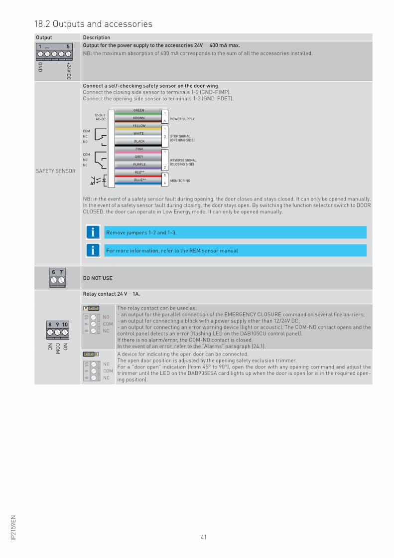
Output Description
+2
4V
DC
GN
D
1 ... 5 Output for the power supply to the accessories 24V 400 mA max.
NB: the maximum absorption of 400 mA corresponds to the sum of all the accessories installed.
SAFETY SENSOR
Connect a self-checking safety sensor on the door wing.
Connect the closing side sensor to terminals 1-2 (GND-PIMP).
Connect the opening side sensor to terminals 1-3 (GND-PDET).
12-24 V
AC-DC
COM
NC
NO
COM
NO
NC
1
5
1
3
1
2
5
4
GREEN
BROWN
YELLOW
WHITE
BLACK
PINK
GREY
PURPLE
RED**
BLUE**
POWER SUPPLY
STOP SIGNAL
(OPENING SIDE)
REVERSE SIGNAL
(CLOSING SIDE)
MONITORING
NB: in the event of a safety sensor fault during opening, the door closes and stays closed. It can only be opened manually.
In the event of a safety sensor fault during closing, the door stays open. By switching the function selector switch to DOOR
CLOSED, the door can operate in Low Energy mode. It can only be opened manually.
6 7DO NOT USE
8 9 10N
O
CO
M
NC
Relay contact 24 V 1A.
89
10 NO
COM
NC
The relay contact can be used as:
- an output for the parallel connection of the EMERGENCY CLOSURE command on several fire barriers;
- an output for connecting a block with a power supply other than 12/24V DC;
- an output for connecting an error warning device (light or acoustic). The COM-NO contact opens and the
control panel detects an error (flashing LED on the DAB105CU control panel).
If there is no alarm/error, the COM-NO contact is closed.
In the event of an error, refer to the “Alarms” paragraph (24.1).
89
10 NO
COM
NC
A device for indicating the open door can be connected.
The open door position is adjusted by the opening safety exclusion trimmer.
For a "door open" indication (from 45° to 90°), open the door with any opening command and adjust the
trimmer until the LED on the DAB905ESA card lights up when the door is open (or is in the required open-
ing position).
18.2 Outputs and accessories
Remove jumpers 1-2 and 1-3.
For more information, refer to the REM sensor manualii
42 IP2
15
9E
N
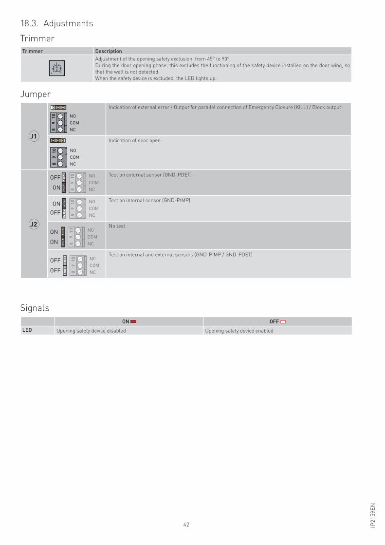
18.3. Adjustments
Trimmer
Trimmer Description
Adjustment of the opening safety exclusion, from 45° to 90°.
During the door opening phase, this excludes the functioning of the safety device installed on the door wing, so
that the wall is not detected.
When the safety device is excluded, the LED lights up.
Jumper
J1
89
10 NO
COM
NC
Indication of external error / Output for parallel connection of Emergency Closure (KILL) / Block output
NO
COM
NC89
10
Indication of door open
J2
89
10 NO
COM
NC
OFF
ON
Test on external sensor (GND-PDET)
OFF
ON
89
10 NO
COM
NC
Test on internal sensor (GND-PIMP)
89
10 NO
COM
NC
ON
ON
No test
89
10 NO
COM
NC
OFF
OFF
Test on internal and external sensors (GND-PIMP / GND-PDET)
Signals
ON OFF
LED Opening safety device disabled Opening safety device enabled
43IP2
15
9E
N
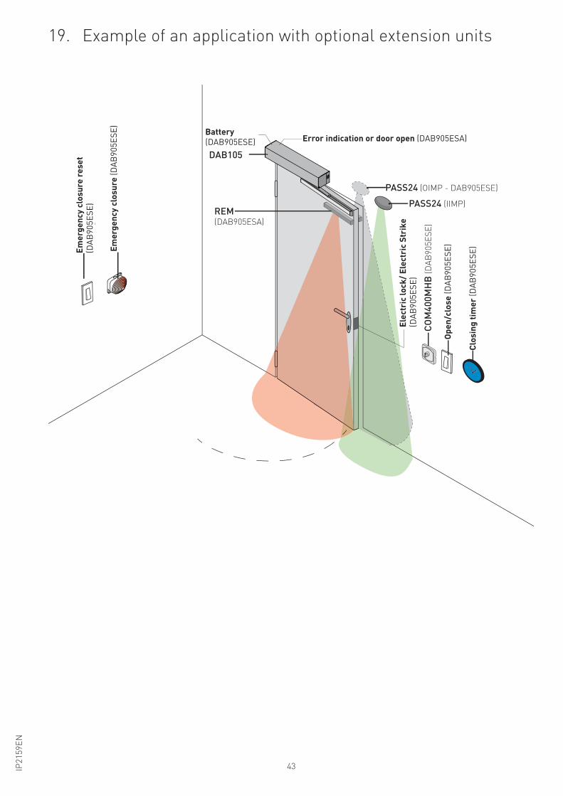
19. Example of an application with optional extension units
PASS24 (OIMP - DAB905ESE)
PASS24 (IIMP)
CO
M4
00
MH
B (
DA
B9
05
ES
E)
Lo
ck
ing
De
vice
(D
AB
90
5E
SE
)
Op
en
/clo
se
(D
AB
90
5E
SE
)
Clo
sin
g t
ime
r (D
AB
90
5E
SE
)
Em
erg
en
cy
clo
sin
g R
es
et
(DA
B9
05
ES
E)
Em
erg
en
cy
clo
sin
g (
DA
B9
05
ES
E)
DAB105
REM(DAB905ESA)
Battery(DAB905ESE)
Error indication or door open (DAB905ESA)Error indication or door open (DAB905ESA)
Emer
genc
y cl
osur
e re
set
(DA
B9
05
ES
E)
Emer
genc
y cl
osur
e (D
AB
90
5E
SE
)
Battery (DAB905ESE)
Elec
tric
lock
/ Ele
ctri
c St
rike
(D
AB
90
5E
SE
)
Ope
n/cl
ose
(DA
B9
05
ES
E)
Clos
ing
timer
(DA
B9
05
ES
E)
44 IP2
15
9E
N
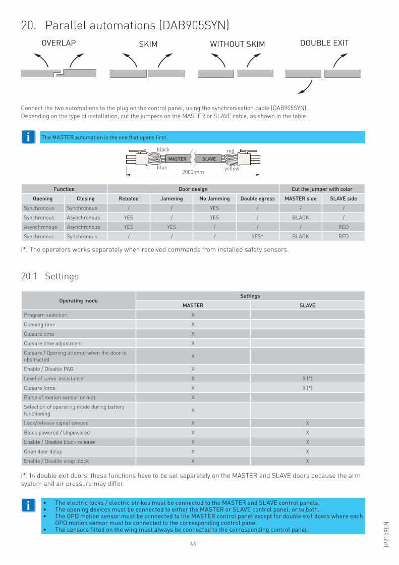
20. Parallel automations (DAB905SYN)
20.1 Settings
Connect the two automations to the plug on the control panel, using the synchronisation cable (DAB905SYN).
Depending on the type of installation, cut the jumpers on the MASTER or SLAVE cable, as shown in the table:
MASTER SLAVE
black
2000 mmyellowblue
red
Operating modeSettings
MASTER SLAVE
Program selection X
Opening time X
Closure time X
Closure time adjustment X
Closure / Opening attempt when the door is
obstructedX
Enable / Disable PAG X
Level of servo-assistance X X (*)
Closure force X X (*)
Pulse of motion sensor or mat X
Selection of operating mode during battery
functioningX
Lock/release signal tension X X
Block powered / Unpowered X X
Enable / Disable block release X X
Open door delay X X
Enable / Disable snap block X X
• The electric locks / electric strikes must be connected to the MASTER and SLAVE control panels.• The opening devices must be connected to either the MASTER or SLAVE control panel, or to both.• The OPD motion sensor must be connected to the MASTER control panel except for double exit doors where each
OPD motion sensor must be connected to the corresponding control panel• The sensors fitted on the wing must always be connected to the corresponding control panel.
SORMONTO SFIORAMENTO SENZA SFIORAMENTO DOPPIA USCITA
The MASTER automation is the one that opens first.i
i
(*) In double exit doors, these functions have to be set separately on the MASTER and SLAVE doors because the arm
system and air pressure may differ.
(*) The operators works separately when received commands from installed safety sensors.
OVERLAP SKIM WITHOUT SKIM DOUBLE EXIT
Function Door design Cut the jumper with color
Opening Closing Rebated Jamming No Jamming Double egress MASTER side SLAVE side
Synchronous Synchronous / / YES / / /
Synchronous Asynchronous YES / YES / BLACK /
Asynchronous Asynchronous YES YES / / / RED
Synchronous Synchronous / / / YES* BLACK RED
45IP2
15
9E
N
BROWN
YELLOW
WH
ITE
BL
UE
RE
D
WH
ITE
YE
LL
OW
BR
OW
N
GR
EE
N
BL
UE
RE
D
WH
ITE
YE
LL
OW
BR
OW
N
GR
EE
N
GR
EE
N
OUTER OPEN SENSOR
SAFETY SENSOR SAFETY SENSOR
FUNCTION
SELECTOR
61
23
45
GND
IIMP
XIMP
OPD
LOUT
24 V
MASTER
MASTER
SLAVE
SLAVE
DAB905SYN (see applications chapter 21)
INNER OPEN SENSOR
SAFETY
SENSOR
INNER
OPEN SENSORFUNCTION
SELECTOR
OUTER
OPEN SENSOR
SAFETY
SENSOR
BROWN
YELLOW
WH
ITE
GR
EE
N
61
23
45
ON
CLTQ
LRN
HOT
PAG
MAT SO
SAR
M1
ARM
2LE
D
1 2 3 4 5
GND
IIMP
XIMP
OPD
LOUT
24 V
+24 V DC
GN
D
EX
IT
OF
F
OP
EN
5
KILL
KEY
O/C
OIMP
GND
12
34
56
78
910
1112
13
EXIT
OFF
UNL
KRST
OPEN
12
-24
V
AC
-DC
CO
M
NC
NO
CO
M
NO
NC
12
-24
V
AC
-DC
CO
M
NC
NO
CO
M
NO
NC
24 V DC
89
101
23
45
NO
COM
NC
QTST
PDET
PIMP
GND
24 V DC
12
34
5
NO
COM
NC
QTST
PDET
PIMP
DA
B1
05
CU
DA
B1
05
CU
DA
B9
05
ES
ED
AB
90
5E
SA
DA
B9
05
ES
A
67
67
GND
89
10
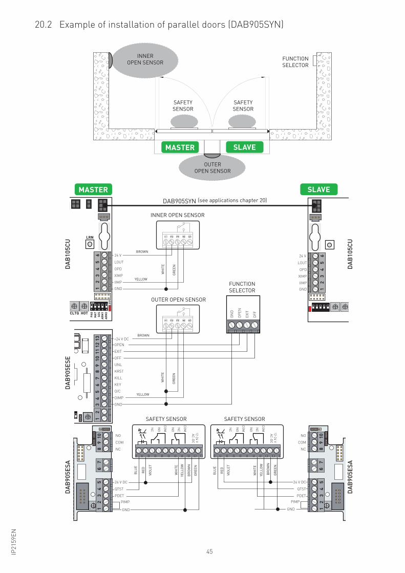
20.2 Example of installation of parallel doors (DAB905SYN)
FUNCTION
SELECTOR
SAFETY
SENSOR
SAFETY
SENSOR
FUNCTION
SELECTOR
SAFETY SENSOR SAFETY SENSOR
OUTER OPEN SENSOR
INNER OPEN SENSOR
(see applications chapter 20)
BROWN
BROWN
YELLOW
WH
ITE
GR
EE
N
YELLOW
WH
ITE
GR
EE
N
WH
ITE
GR
EE
N
BL
UE
RE
D
BL
UE
RE
D
VIO
LE
T
VIO
LE
T
WH
ITE
YE
LL
OW
BR
OW
N
GR
EE
N
YE
LL
OW
BR
OW
N
INNER
OPEN SENSOR
OUTER
OPEN SENSOR
46 IP2
15
9E
N
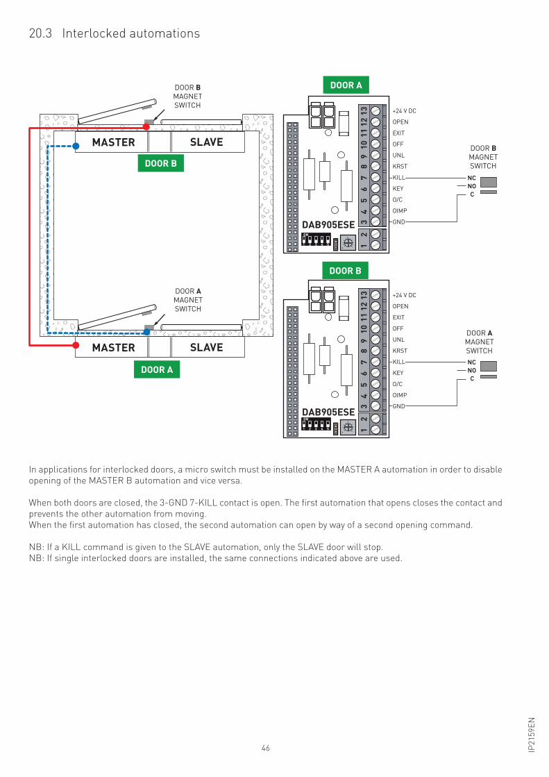
20.3 Interlocked automations
MASTER
DOOR A
DOOR B
SLAVE
MASTER SLAVE
DOOR BMAGNET
SWITCH
DOOR AMAGNET
SWITCH
In applications for interlocked doors, a micro switch must be installed on the MASTER A automation in order to disable
opening of the MASTER B automation and vice versa.
When both doors are closed, the 3-GND 7-KILL contact is open. The first automation that opens closes the contact and
prevents the other automation from moving.
When the first automation has closed, the second automation can open by way of a second opening command.
NB: If a KILL command is given to the SLAVE automation, only the SLAVE door will stop.
NB: If single interlocked doors are installed, the same connections indicated above are used.
C
NC
NO
1 2 3 4 5
ON
+24 V DC
KILL
KEY
O/C
OIMP
GND
12
34
56
78
910
1112
13
OPEN
EXIT
OFF
UNL
KRST
DOOR B
MAGNET
SWITCH
DOOR A
MAGNET
SWITCH
1 2 3 4 5
ON
+24 V DC
KEY
O/C
OIMP
GND
12
34
56
78
910
1112
13
OPEN
EXIT
OFF
UNL
KRST
DOOR A
DOOR B
C
NC
KILL
DAB905ESE
DAB905ESE
NO
DOOR A
MAGNET
SWITCH
DOOR B MAGNET
SWITCH
DOOR B
MAGNET
SWITCH
DOOR A
MAGNET
SWITCH
DOOR A
DOOR B
DOOR A
DOOR B
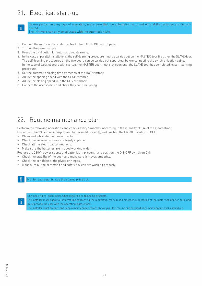
47IP2
15
9E
N
22. Routine maintenance planPerform the following operations and checks every 6 months, according to the intensity of use of the automation.
Disconnect the 230V~ power supply and batteries (if present), and position the ON-OFF switch on OFF:
• Clean and lubricate the moving parts.
• Check the securing screws are firmly in place.
• Check all the electrical connections.
• Make sure the batteries are in good working order.
Restore the 230V~ power supply and batteries (if present), and position the ON-OFF switch on ON:
• Check the stability of the door, and make sure it moves smoothly.
• Check the condition of the pivots or hinges.
• Make sure all the command and safety devices are working properly.
NB: for spare parts, see the spares price list.i
21. Electrical start-up
1. Connect the motor and encoder cables to the DAB105CU control panel.
2. Turn on the power supply.
3. Press the LRN button for automatic self-learning.
4. In the case of parallel installations, the self-learning procedure must be carried out on the MASTER door first, then the SLAVE door.
The self-learning procedures on the two doors can be carried out separately, before connecting the synchronisation cable.
In the case of parallel doors with overlap, the MASTER door must stay open until the SLAVE door has completed its self-learning
procedure.
5. Set the automatic closing time by means of the HOT trimmer.
6. Adjust the opening speed with the OPSP trimmer.
7. Adjust the closing speed with the CLSP trimmer.
8. Connect the accessories and check they are functioning.
Before performing any type of operation, make sure that the automation is turned off and the batteries are discon-
nected.
The trimmers can only be adjusted with the automation idle.i
iOnly use original spare parts when repairing or replacing products.
The installer must supply all information concerning the automatic, manual and emergency operation of the motorised door or gate, and
must provide the user with the operating instructions.
The installer must prepare and keep a maintenance record showing all the routine and extraordinary maintenance work carried out.
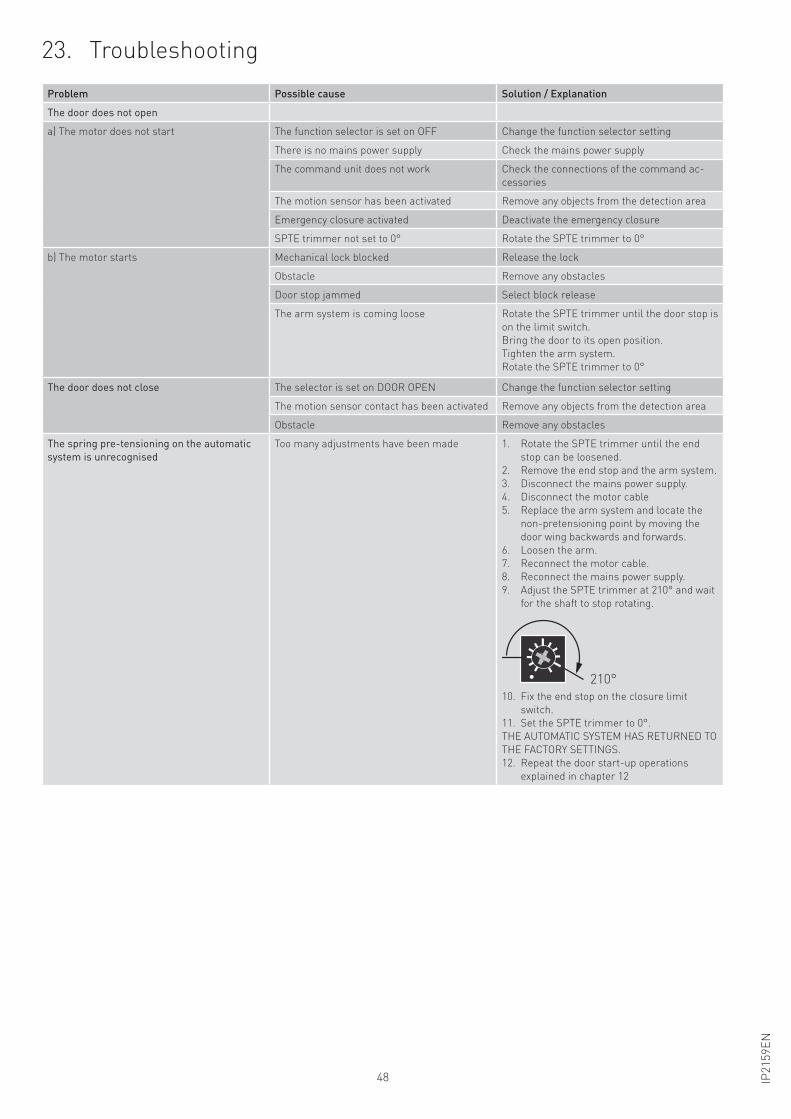
48 IP2
15
9E
N
23. Troubleshooting
Problem Possible cause Solution / Explanation
The door does not open
a) The motor does not start The function selector is set on OFF Change the function selector setting
There is no mains power supply Check the mains power supply
The command unit does not work Check the connections of the command ac-
cessories
The motion sensor has been activated Remove any objects from the detection area
Emergency closure activated Deactivate the emergency closure
SPTE trimmer not set to 0° Rotate the SPTE trimmer to 0°
b) The motor starts Mechanical lock blocked Release the lock
Obstacle Remove any obstacles
Door stop jammed Select block release
The arm system is coming loose Rotate the SPTE trimmer until the door stop is
on the limit switch.
Bring the door to its open position.
Tighten the arm system.
Rotate the SPTE trimmer to 0°
The door does not close The selector is set on DOOR OPEN Change the function selector setting
The motion sensor contact has been activated Remove any objects from the detection area
Obstacle Remove any obstacles
The spring pre-tensioning on the automatic
system is unrecognised
Too many adjustments have been made 1. Rotate the SPTE trimmer until the end
stop can be loosened.
2. Remove the end stop and the arm system.
3. Disconnect the mains power supply.
4. Disconnect the motor cable
5. Replace the arm system and locate the
non-pretensioning point by moving the
door wing backwards and forwards.
6. Loosen the arm.
7. Reconnect the motor cable.
8. Reconnect the mains power supply.
9. Adjust the SPTE trimmer at 210° and wait
for the shaft to stop rotating.
210°
10. Fix the end stop on the closure limit
switch.
11. Set the SPTE trimmer to 0°.
THE AUTOMATIC SYSTEM HAS RETURNED TO
THE FACTORY SETTINGS.
12. Repeat the door start-up operations
explained in chapter 12
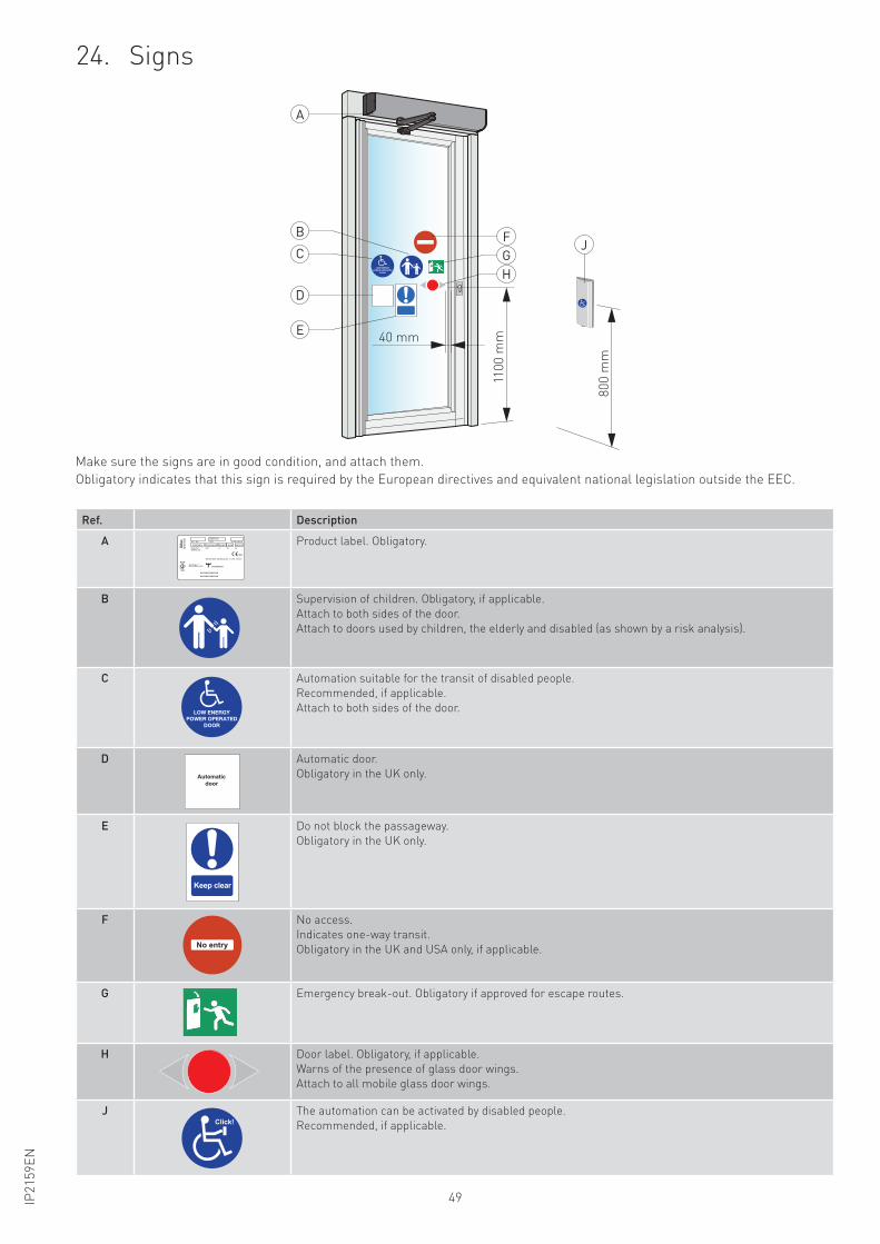
49IP2
15
9E
N
24. Signs
80
0 m
m
110
0 m
m40 mm
A
B
C
D
E
F
GJ
H
Ref. Description
A
xxxxxxxxxxxxxxxxxxxxxxxxxx
TYPEART. NO. YEAR+WEEK
XXEN ISO 9001 Certificate No: 911828, 956538
SITAC1422 xxxxxxxxx1002
XX/XXXXXXXXHzPROJECT
SERIAL NO.
XXXXXXXXXX
DAB105
WXXXXAVAC
Product label. Obligatory.
B Supervision of children. Obligatory, if applicable.
Attach to both sides of the door.
Attach to doors used by children, the elderly and disabled (as shown by a risk analysis).
C Automation suitable for the transit of disabled people.
Recommended, if applicable.
Attach to both sides of the door.
D
Automaticdoor
Automatic door.
Obligatory in the UK only.
E
Keep clear
Do not block the passageway.
Obligatory in the UK only.
F
No entry
No access.
Indicates one-way transit.
Obligatory in the UK and USA only, if applicable.
G Emergency break-out. Obligatory if approved for escape routes.
H Door label. Obligatory, if applicable.
Warns of the presence of glass door wings.
Attach to all mobile glass door wings.
JClick!
The automation can be activated by disabled people.
Recommended, if applicable.
Make sure the signs are in good condition, and attach them.
Obligatory indicates that this sign is required by the European directives and equivalent national legislation outside the EEC.

IP2
15
9E
N
Entrematic Group AB
Lodjursgatan 10
SE-261 44, Landskrona
Sweden
www.entrematic.com