control system of the articulated arm braking …
TRANSCRIPT
28TH DAAAM INTERNATIONAL SYMPOSIUM ON INTELLIGENT MANUFACTURING AND AUTOMATION
DOI: 10.2507/28th.daaam.proceedings.139
CONTROL SYSTEM OF THE ARTICULATED ARM BRAKING
MECHATRONIC MACHINE (AABMM)
Mikhail Solovyev, Vorotnikov Andrei, Daniil Klimov,
Kovalskii Vladislav, Yuri Poduraev
This Publication has to be referred as: Solovyev, M[ikhail]; Vorotnikov, A[ndrei]; Klimov, D[aniil]; Kovalskii,
V[ladislav] & Poduraev, Y[uriy] V[.] (2017). Control System of the Articulated Arm Braking Mechatronic Machine
(AABMM), Proceedings of the 28th DAAAM International Symposium, pp.1002-1009, B. Katalinic (Ed.), Published by
DAAAM International, ISBN 978-3-902734-11-2, ISSN 1726-9679, Vienna, Austria
DOI: 10.2507/28th.daaam.proceedings.139
Abstract
An approach to solving the problem of fixing objects in space with a given position and orientation is considered in the
article. The concept of the Articulated Arm Braking Mechatronic Machine (AABMM) is described, which allows solving
this problem in various fields of science and technology. The synthesis of the control system based on modular approach
has been carried out. A rig for testing and calibration of sensors, designed to improve the reliability of the system and the
accuracy of the feedback loop elements was developed. The proposed control system will allow to operate the AABMM
with different kinematic structures and function sets.
Keywords: control system; medical robotics; mechatronic; sensor calibration; articulated arm
1. Introduction
In various areas of human activity, there are tasks that require fixing objects in space with a given position and
orientation, relative to other objects. Similar problems can be found in industry, where it is required to keep the workpiece
or tool in a certain position during processing, or in cinematography, to position the imaging equipment during process
shooting for alignment with 3D-graphics [1]. A wide class of similar problems can be found in medicine. For example,
in neurosurgery, when performing operations in the region of the spinal cord or brain, it is necessary to fix the position
of the medical instruments relative to the operating field for their further accurate surgical insertion into the living tissue
of the patient. Precise positioning of the instruments at the time of the medical operation reduces the risks caused by the
human factor, ensures a low invasiveness of the intervention, increases the speed of the operation. To effectively solve
these problems, the concept of a mechatronic device – Articulated Arm Braking Mechatronic Machine (AABMM) is
proposed, consisting of a series of links capable of fixing relative to each other in a certain position necessary for the user,
with built-in brakes A similar approach to the solution of these problems in the field of medicine is considered in [2,3],
however, despite the close solution in link fixing, there are no positioning devices provided, so the navigation of the
medical instrument is done manually.
- 1002 -

28TH DAAAM INTERNATIONAL SYMPOSIUM ON INTELLIGENT MANUFACTURING AND AUTOMATION
In the RSSS (Robotic Spinal Surgical System) system described in [4,5], it is proposed to use a manipulator capable
of working in a collaborative mode, allowing the individual links to move manually, which makes it functionally close to
the AABMM. Nevertheless, the problem of navigation in RSSS is solved on the basis of stereo photogrammetry, using
an external stationary stereo camera and markers on the end effector of the manipulator. In AABMM, in turn, precise
angular sensors are used to determine the position, thus allowing navigation without external measuring equipment.
The aim of the work is to cover the problems of design and development of the electronic subsystem of the AABMM,
including low-level software. The paper considers the synthesis of the structure of the modular control system of the
mechatronic device, the approaches to transferring and receiving information between the elements of this structure, as
well as the development of the rig and experimental studies for testing and calibration of absolute position sensors - an
essential element of AABMM.
2. Description of the kinematics and internal components of the AABMM
The developed mechatronic device is an articulated arm of the open kinematic model. Inside of the joints of the
kinematic pairs, precision angular position sensors and brake devices are located. The structure of the kinematic scheme,
the number and the size of the links can vary depending on the requirements of operation. The general view of the
AABMM (Articulated Arm Braking Mechatronic Machine) is shown in Figure 1. The main function of this device is to
limit the movements of the end effector to perform the tasks assigned. When performing an operation, the brake devices
fixes the articulated arm and does not allow the end effector to deviate from the preset position.
The position and orientation of the end effector is specified to the AABMM in the control program, as a set of lines
of code necessary for execution. After loading the control program, the control system, in which the kinematic model is
set, reports the necessary moving commands to the user. The movement of the end effector from one position to another
takes place manually and can be done in two ways: by moving around or along each selected axis to the specified position
one by one, or by manually moving the articulated arm to the desired position, and then fixing all the joints. The braking
devices can be switched on and off by means of control elements located on the AABMM body.
Fig. 1. Kinematic models of typical AABMM
The basis of the mathematical description of AABMM in the control system is the direct kinematic problem. The
solution of the direct kinematics problem allows to transform the space of generalized coordinates of the position of the
AABMM joints into the Cartesian space by means of several transitions from the previous link to the next one. Each
transition is carried out in accordance with certain rules established by Denavite and Hartenberg [6] and is described by
a homogeneous transformation matrix of 4 by 4 dimensions:
1 (z ,d ) ( , ) ( , ) ( , )i
i i i i i i i i iA Trans Rot z Trans x a Rot x (1)
where (h , )i iTrans and Rot(h , )i i – homogeneous transfer and rotation transformation matrices, respectively, h i
- rotation or transfer axis ( ix , iy or iz ) i coordinate systems, i - angle of rotation or length of transfer i coordinate
system to one of the geometric parameters: d i , i , ia , i . The number of matrices corresponds to the number of joints
in the mechanism.
- 1003 -
28TH DAAAM INTERNATIONAL SYMPOSIUM ON INTELLIGENT MANUFACTURING AND AUTOMATION
For the developed kinematic model, it is necessary to perform a calibration by determining the actual values of the
geometric parameters ( d i , i , ia , i ): displacements of generalized coordinates (initial relative position of links), real
lengths of links and displacements between them. Calibration of AABMM is possible to perform in a variety of
approaches, for example, using:
• Identification of all geometric parameters of the kinematic model of the control system. For this purpose, the
coordinates of the points of the position of the working element, measured throughout the entire working area of the
AABMM, are approximated.
• Definition of individual geometric elements of the robot using CPA (circle point analysis) and further transformation
of the entire kinematic model.
A more detailed description of these approaches was proposed in [Error! Reference source not found.- Error!
Reference source not found.].
3. Modular control system of the AABMM.
When designing the control system for AABMM, a modular approach was used [10]. This approach consists in
combining devices for various purposes into a constructively and functionally independent product. For AABMM, it is
rational to combine the sensor and the brake in each joint into a separate module. All modules include a unified control
board. In this board, feedback is created by means of a high-frequency survey of absolute angular position sensors and,
in accordance with the specified program or an external command from other modules, interaction with the control object
(brake) occurs.
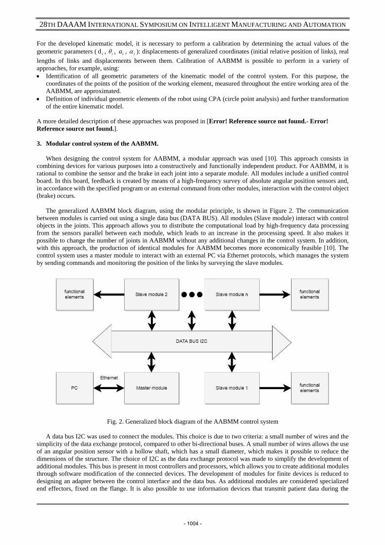
The generalized AABMM block diagram, using the modular principle, is shown in Figure 2. The communication
between modules is carried out using a single data bus (DATA BUS). All modules (Slave module) interact with control
objects in the joints. This approach allows you to distribute the computational load by high-frequency data processing
from the sensors parallel between each module, which leads to an increase in the processing speed. It also makes it
possible to change the number of joints in AABMM without any additional changes in the control system. In addition,
with this approach, the production of identical modules for AABMM becomes more economically feasible [10]. The
control system uses a master module to interact with an external PC via Ethernet protocols, which manages the system
by sending commands and monitoring the position of the links by surveying the slave modules.
Fig. 2. Generalized block diagram of the AABMM control system
A data bus I2C was used to connect the modules. This choice is due to two criteria: a small number of wires and the
simplicity of the data exchange protocol, compared to other bi-directional buses. A small number of wires allows the use
of an angular position sensor with a hollow shaft, which has a small diameter, which makes it possible to reduce the
dimensions of the structure. The choice of I2C as the data exchange protocol was made to simplify the development of
additional modules. This bus is present in most controllers and processors, which allows you to create additional modules
through software modification of the connected devices. The development of modules for finite devices is reduced to
designing an adapter between the control interface and the data bus. As additional modules are considered specialized
end effectors, fixed on the flange. It is also possible to use information devices that transmit patient data during the
- 1004 -

28TH DAAAM INTERNATIONAL SYMPOSIUM ON INTELLIGENT MANUFACTURING AND AUTOMATION
operation or the parameters of the working environment directly by the flange. There are 7 modules for joint management
and 6 additional modules for connection of end effectors.
During the development of the control system, two changes were made to the data bus. The first change is to increase
the voltage on the two power wires. The voltage value was increased from 5 volts to 12. This is due to the need for
increased supply of brake components in the module. The second change is related to the data rate on the bus clock and
data bus. From the "classic" standard value of 100 Kbits / s, it was increased to another speed value of 400 Kbits / s. This
is due to the provision of a time reserve for data transmission in case of a critical situation, for example, stopping of the
operation of all modules by the PC command.
In addition to the implemented method of instant brake locking in all modules, in response to a specialized signal, it
is possible to transmit an emergency command sequentially to each module. The time for such a transmission should not
exceed the button contact jitter processing time of 0.01 seconds. Although the maximum design response time of the
system is 0.0026 seconds, under operating conditions, data and data processing errors are possible, so the speed has been
increased with a safety factor of 4. Thus, a balance was observed between the number of wires and the speed of the
system, depending on the data transfer rate on the bus.
Let us consider the structure and operation of the modules in more detail. A detailed block diagram is shown in Figure
4. The slave module (Figure 4a) produces high-frequency data reading from the position sensor. The data is written to the
ring buffer of the device and, when requested via the data bus, it can return both the last recorded value and the entire
buffer. Brake control in the module occurs in accordance with the program or commands received via the data bus. The
module's functionality allows you to enable or disable the brake depending on the angle of relative position of the links
in the joint, from the command on the data bus or from the command of the control on the housing, such as a button. As
a controller, the AVR ATMEGA328P microcontroller is used.
The I2C interface module of the microcontroller is directly connected to the common data bus. The slave module has
three control elements: a brake, a sensor and a control board mounted on the body. The brake is connected to the board
via a galvanic isolation using a relay. This is due to the difference in the brake control voltage and the operating voltage
of the microcontroller. A power converter is used to power the entire system, which provides 12 volts for controlling the
magnet and 5 volts for powering the controller and sensor. The absolute position sensor is connected to the controller via
the RS-422 / RS-485 signal converter.
The task of the master module (Figure 4 b) is to control the system by sending commands and monitoring the position
of the links by low-frequency surveying of slave devices. In addition, it communicates with an external control device, a
personal computer through the physical network interface rj45 over TCP / IP protocols.
Fig. 4. Slave (a) and master (b) devices.
In the master module, the microcontroller as well as in the slave is directly connected to the data bus. The controller
is connected to the PC by the ENC28J60 chip, which is an Ethernet controller designed to work with connections based
on the 10BASE-T family interfaces. Control of this chip is carried out using the SPI protocol. For connection to a personal
computer, a connector is used for the rj45 interface of the magjack type.
The master module is the master on the data bus. It initiates the reception and transmission of data with slave modules.
Thus, there is no possibility of overlaying information from two different modules. This implementation allows the use
of basic TCP / IP protocol tools to communicate with the device and interpret data in any certified software [11], which
is designed to work with a medical device.
- 1005 -

28TH DAAAM INTERNATIONAL SYMPOSIUM ON INTELLIGENT MANUFACTURING AND AUTOMATION
4. Testing and calibration rig for absolute position sensors.
It is possible to use AABMM in medical practice to perform operations on a patient. Therefore, the measuring devices
used in medical AABMM should have increased requirements for accuracy and reliability. As measuring devices for
AABMM, it is advisable to use absolute position sensors, which, unlike incremental sensors, save information about the
current position when the power is turned off. Absolute position sensors are installed in the joints and allow to determine
the position of the next link relative to the previous one. In connection with the increased requirements for absolute
position sensors, it is necessary to evaluate their accuracy against the manufacturer's specified qualitative characteristics.
A specialized rig has been developed for the testing of angle sensors. Its principle of operation is to test a less accurate
sensor using a different, more accurate one. Both sensors are fixed to a single shaft, which moves to an angular discrete
smaller than the accuracy of the sensor being tested. For each discrete value is read from the two sensors, which are
recorded in a look up table. Values of the look up table for full shaft rotation are used to determine the actual characteristics
of the sensor being tested. With the help of such a specialized rig, it is also possible to calibrate the sensors, increasing
their accuracy. The appearance of the stand is shown in Figure 5. It combines two sensors through a single shaft, the
rotation of which provides a stepper motor through a worm gearbox. To reduce the initial value of the eccentricity and
the relative inclination of the sensors, they are located at a minimum distance from each other. In this case, the design of
the rig is designed in such a way, that it makes it possible to replace the tested absolute sensors without disassembly.
Fig. 5. Experimental rig for testing and calibration of sensors
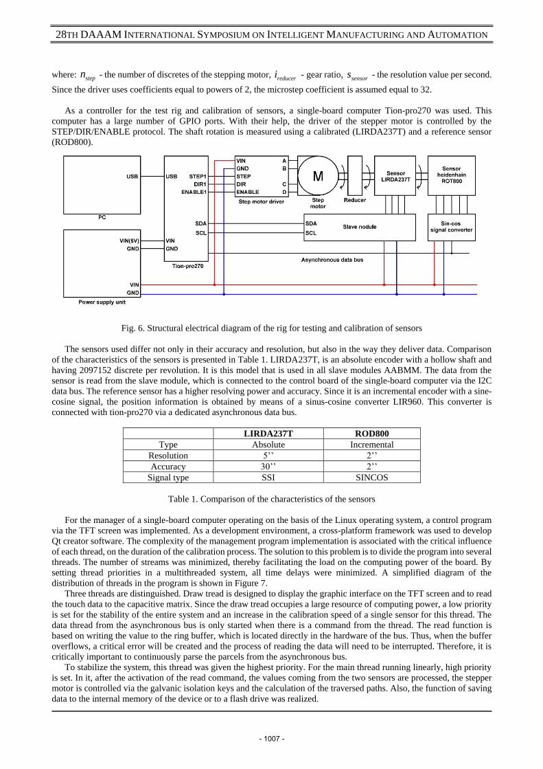
The block diagram of the developed rig for testing absolute sensors is shown in Figure 6. The stepper motor with a
worm gear is used as the device for creating the angular movement of the shaft. The stepper motor is controlled by a
driver with the ability to generate a microstep. Microstepping allows you to "divide" the steps of the motor, thereby
reducing the discretion of moving the common shaft. The microstep selection is carried out in accordance with the
following formula:
360 *60*6016.2
* *kmicrostep
n i ssensorstep reducer
(2)
- 1006 -
28TH DAAAM INTERNATIONAL SYMPOSIUM ON INTELLIGENT MANUFACTURING AND AUTOMATION
where: stepn - the number of discretes of the stepping motor, reduceri - gear ratio,
sensors - the resolution value per second.
Since the driver uses coefficients equal to powers of 2, the microstep coefficient is assumed equal to 32.
As a controller for the test rig and calibration of sensors, a single-board computer Tion-pro270 was used. This
computer has a large number of GPIO ports. With their help, the driver of the stepper motor is controlled by the
STEP/DIR/ENABLE protocol. The shaft rotation is measured using a calibrated (LIRDA237T) and a reference sensor
(ROD800).
Fig. 6. Structural electrical diagram of the rig for testing and calibration of sensors
The sensors used differ not only in their accuracy and resolution, but also in the way they deliver data. Comparison
of the characteristics of the sensors is presented in Table 1. LIRDA237T, is an absolute encoder with a hollow shaft and
having 2097152 discrete per revolution. It is this model that is used in all slave modules AABMM. The data from the
sensor is read from the slave module, which is connected to the control board of the single-board computer via the I2C
data bus. The reference sensor has a higher resolving power and accuracy. Since it is an incremental encoder with a sine-
cosine signal, the position information is obtained by means of a sinus-cosine converter LIR960. This converter is
connected with tion-pro270 via a dedicated asynchronous data bus.
LIRDA237T ROD800
Type Absolute Incremental
Resolution 5’’ 2’’
Accuracy 30’’ 2’’
Signal type SSI SINCOS
Table 1. Comparison of the characteristics of the sensors
For the manager of a single-board computer operating on the basis of the Linux operating system, a control program
via the TFT screen was implemented. As a development environment, a cross-platform framework was used to develop
Qt creator software. The complexity of the management program implementation is associated with the critical influence
of each thread, on the duration of the calibration process. The solution to this problem is to divide the program into several
threads. The number of streams was minimized, thereby facilitating the load on the computing power of the board. By
setting thread priorities in a multithreaded system, all time delays were minimized. A simplified diagram of the
distribution of threads in the program is shown in Figure 7.
Three threads are distinguished. Draw tread is designed to display the graphic interface on the TFT screen and to read
the touch data to the capacitive matrix. Since the draw tread occupies a large resource of computing power, a low priority
is set for the stability of the entire system and an increase in the calibration speed of a single sensor for this thread. The
data thread from the asynchronous bus is only started when there is a command from the thread. The read function is
based on writing the value to the ring buffer, which is located directly in the hardware of the bus. Thus, when the buffer
overflows, a critical error will be created and the process of reading the data will need to be interrupted. Therefore, it is
critically important to continuously parse the parcels from the asynchronous bus.
To stabilize the system, this thread was given the highest priority. For the main thread running linearly, high priority
is set. In it, after the activation of the read command, the values coming from the two sensors are processed, the stepper
motor is controlled via the galvanic isolation keys and the calculation of the traversed paths. Also, the function of saving
data to the internal memory of the device or to a flash drive was realized.
- 1007 -

28TH DAAAM INTERNATIONAL SYMPOSIUM ON INTELLIGENT MANUFACTURING AND AUTOMATION
Fig. 7. Thread diagram.
To fully compensate the eccentricity and the mutual tilt of the two sensors, an algorithm for processing the look up
table was implemented. After obtaining a look up table between the data coming from the calibrated sensor and the
reference sensor data, the signal is processed. The processing consists in the formation of an error signal of the sensor
readings (blue graph). Next, a direct Fourier transform for the error signal and a transition to the frequency domain are
performed. The first two harmonics create a compensating error signal and perform its inverse transformation from the
frequency domain to the time domain (red graph). By subtracting the compensating error signal from the original signal,
the eccentricity and mutual tilt of the two sensors are compensated and a look up table is created (green graph). Calibration
is carried out by transferring table values to the memory of the module working with the calibrated sensor. The signal
graphs are shown in Figure 8.
Fig. 8. Graphs of received sensor signals during calibration.
- 1008 -

28TH DAAAM INTERNATIONAL SYMPOSIUM ON INTELLIGENT MANUFACTURING AND AUTOMATION
5. Conclusion
The article considered the problem of developing devices for fixing objects in space with a given position and
orientation. In particular, a solution for the electronic control subsystem is proposed. The solution is based on the modular
principle, which allows to combine control objects in the joints into functionally independent devices connected by a
single data bus. In this way, it is possible to easily modify the lengths of the links, the number of joints and the device
functionality by developing additional modules. This makes this type of device applicable for various classes of tasks,
including operations in medical practice. Solutions for the electronic subsystem are described, structural and schematic
diagrams and low-level software were developed. An approach to testing and calibrating the sensors of the modules is
also described. The proposed solution in the form of a specialized sensor calibration rig is aimed at automating the
processes of data acquisition, processing and analysis. Based on the described developments, it is planned to create a
prototype of the AABMM, for use in medical practice.
6. Acknowledgments
The Ministry of Education and Science of Russia as part of State assignment № 9.3408.2017/4.6 supported the work.
7. References
[1] Klimov, D.; Poduraev, Y. ( 2014). Design and Experimental Testing of a Robotic System for High Speed Recording,
Proceedings of the 25th International DAAAM Symposium, ISSN 1877-7058, ISBN 978-3-901509-97-1, Katalinic,
B. (Ed.), pp.1332-1337, Published by DAAAM International, Vienna, Austria, doi: 10.1016/j.proeng.2015.01.501
[2] Hu, Y.; Zhang, J.; Li, C.; Cheng, S; Wang, L. (2008). Safety design of an Assisting Robotic Arm for minimally
invasive thoracic surgery, Proceedings of the 2008. ROBIO 2008. IEEE International Conference on. – IEEE, 2009.
, pp. 709-714, IEEE, Bangkok, Thailand, 10.1109/ROBIO.2009.4913088
[3] Wang, X; Tian, C; Duan, X.; Gu, Y.; Huang N. (2014). A medical manipulator system with lasers in photodynamic
therapy of port wine stains BioMed research international Т. 2014.
[4] Tian, W.; Han, X.; Liu, B.; Liu, Y.; Hu, Y.; Han, X. (2014) A robot-assisted surgical system using a force-image
control method for pedicle screw insertion, PloS one, Vol 9,No 1, 01.2014, pp. 1-9
[5] Hu Y.; Jin H.; Zhang L.; Zhang P. & Zhang J, (2014) State recognition of pedicle drilling with force sensing in a
robotic spinal surgical system, IEEE/ASME Transactions on Mechatronics, 05. 2014, Vol 19, No 1. P. 357-365,
Shenzhen, China
[6] Denavit J. & Hartenberg R. (1955) A kinematic notation for lower-pair mechanisms based on matrices, Transactions
of ASME, 09.1955, Vol 22, No 2, pp. 215-221, ISSN:0098-2202
[7] Mooring B.; Roth Z. & Driels M. Fundamentals of manipulator calibration, John Wiley & Sons, ISBN 0-471-50864-
0, United States
[8] Vorotnicov, A.; Isaev, A.; Romash, E.; Ilyukhin Yu.; Bashevskaya, O. & Poduraev Y. (2015) Geometrical Approach
for Industrial Robot Axis Calibration Using Laser Tracker., Proceedings of the 26th DAAAM International
Symposium, ISSN 1877-7058, ISBN 978-3-901509-97-1, Katalinic, B. (Ed.), pp. 0897-0904, Published by DAAAM
International, Vienna, Austria, DOI: 10.2507/26th.daaam.proceedings.125
[9] Vorotnicov, A.; Romash, E.; Isaev, A.; Bashevskaya, O.; Bianchi G. & Poduraev Y. (2016). Uncertainty Estimation
of Axes Direction Determination of Industrial Robot Using an Ellipsoid Concentration Model, Proceedings of the
27th DAAAM International Symposium, , ISBN 978-3-902734-08-2, ISSN 1726-9679, B. Katalinic (Ed.), pp.0480-
0486, Published by DAAAM International, Vienna, Austria. DOI: 10.2507/27th.daaam.proceedings.072
[10] Lopota, V. & Yurevich E. (2011). Stages and development prospects of robotic systems design modular principle.
St. Petersburg Polytechnic University Journal of Engineering Science and Technology, Vol 2, 09.2011, pp. 98-103,
ISSN: 1994-2354
[11] ISO/IEC 62304 The instrumental standard for medical device software
- 1009 -