tw4-tvr-aia task title: articulated inspection arm (aia) · includes the design, manufacture and...
TRANSCRIPT
- 73 - EFDA Technology / Vessel-In Vessel / Remote Handling
TW4-TVR-AIA Task Title: ARTICULATED INSPECTION ARM (AIA) INTRODUCTION This project takes place in the Remote Handling (RH) activities for the next step of the fusion reactor ITER. The aim of the R&D program is to demonstrate the feasibility of close inspection of the divertor cassettes and the Vacuum Vessel first wall of ITER. We assumed that a long reach and limited payload carrier penetrates the first wall using the 6 penetrations evenly distributed around the machine and foreseen for the In-Vessel Viewing System (IVVS). The need to access closer than the IVVS to the vacuum vessel first wall and the divertor cassettes had been identified. This is required when considering inspection with other processes as camera or leak detection. The work performed under the EFDA-CSU Workprogramme includes the design, manufacture and testing of an articulated device demonstrator called Articulated Inspection Arm (AIA). The first phase of the project concerned the analysis to define a realistic conceptual design of the equipment that fit the requirements of inspection operation inside the vacuum vessel. A scale one mock-up (previously called In Vessel Penetration (IVP)) was manufactured, focusing on the electro mechanical test in air and at room temperature of a single module. The test campaign of a 2 degrees of freedom module was finally successfully performed and gave confidence of structural resistance of the system which was the first essential design driver to verify. In parallel, a feasibility study of operation under vacuum and temperature was performed to select the possible applicable technologies. At this step it has been identified the need for developments of specific new technologies in particular for bearings, actuators and electronics. This development required proof of principle test phase. Therefore a scale one full module with 2 degrees of freedom was manufactured and tested under vacuum and temperature conditions at Tore Supra facilities.
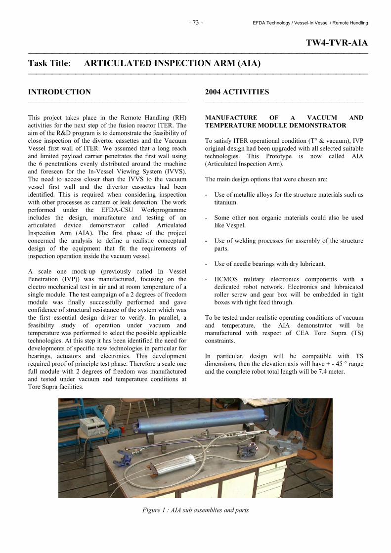
2004 ACTIVITIES MANUFACTURE OF A VACUUM AND TEMPERATURE MODULE DEMONSTRATOR To satisfy ITER operational condition (T° & vacuum), IVP original design had been upgraded with all selected suitable technologies. This Prototype is now called AIA (Articulated Inspection Arm). The main design options that were chosen are: - Use of metallic alloys for the structure materials such as
titanium. - Some other non organic materials could also be used
like Vespel. - Use of welding processes for assembly of the structure
parts. - Use of needle bearings with dry lubricant. - HCMOS military electronics components with a
dedicated robot network. Electronics and lubraicated roller screw and gear box will be embedded in tight boxes with tight feed through.
To be tested under realistic operating conditions of vacuum and temperature, the AIA demonstrator will be manufactured with respect of CEA Tore Supra (TS) constraints. In particular, design will be compatible with TS dimensions, then the elevation axis will have + - 45 ° range and the complete robot total length will be 7.4 meter.
Figure 1 : AIA sub assemblies and parts
- 74 - EFDA Technology / Vessel-In Vessel / Remote Handling
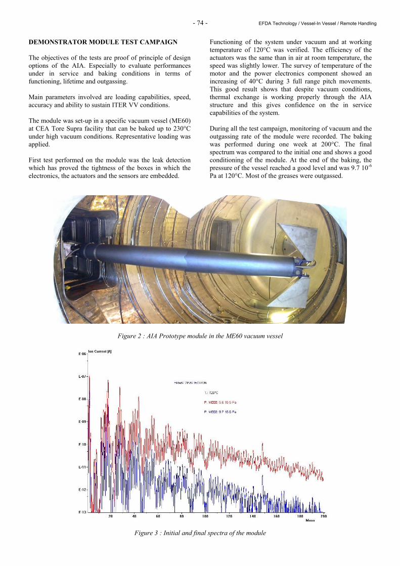
DEMONSTRATOR MODULE TEST CAMPAIGN The objectives of the tests are proof of principle of design options of the AIA. Especially to evaluate performances under in service and baking conditions in terms of functioning, lifetime and outgassing. Main parameters involved are loading capabilities, speed, accuracy and ability to sustain ITER VV conditions. The module was set-up in a specific vacuum vessel (ME60) at CEA Tore Supra facility that can be baked up to 230°C under high vacuum conditions. Representative loading was applied. First test performed on the module was the leak detection which has proved the tightness of the boxes in which the electronics, the actuators and the sensors are embedded.
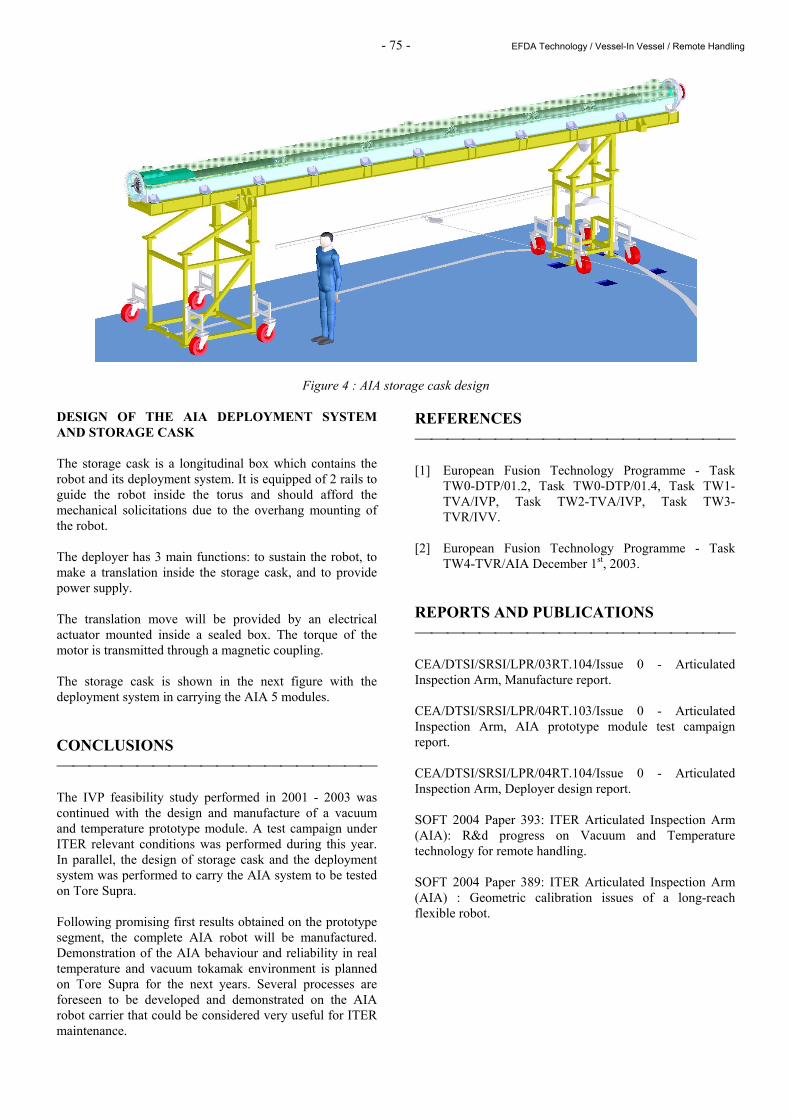
Functioning of the system under vacuum and at working temperature of 120°C was verified. The efficiency of the actuators was the same than in air at room temperature, the speed was slightly lower. The survey of temperature of the motor and the power electronics component showed an increasing of 40°C during 3 full range pitch movements. This good result shows that despite vacuum conditions, thermal exchange is working properly through the AIA structure and this gives confidence on the in service capabilities of the system. During all the test campaign, monitoring of vacuum and the outgassing rate of the module were recorded. The baking was performed during one week at 200°C. The final spectrum was compared to the initial one and shows a good conditioning of the module. At the end of the baking, the pressure of the vessel reached a good level and was 9.7 10-6 Pa at 120°C. Most of the greases were outgassed.
Figure 2 : AIA Prototype module in the ME60 vacuum vessel
Figure 3 : Initial and final spectra of the module
- 75 - EFDA Technology / Vessel-In Vessel / Remote Handling
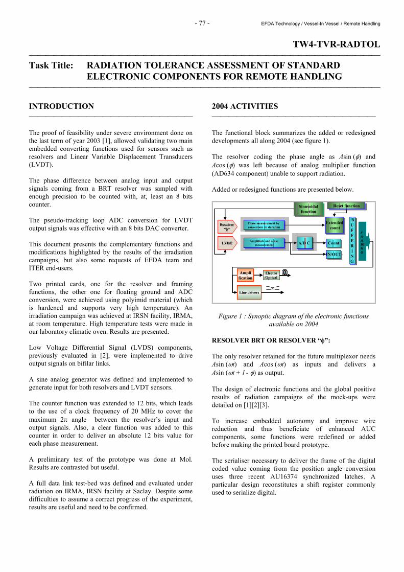
Figure 4 : AIA storage cask design DESIGN OF THE AIA DEPLOYMENT SYSTEM AND STORAGE CASK The storage cask is a longitudinal box which contains the robot and its deployment system. It is equipped of 2 rails to guide the robot inside the torus and should afford the mechanical solicitations due to the overhang mounting of the robot. The deployer has 3 main functions: to sustain the robot, to make a translation inside the storage cask, and to provide power supply. The translation move will be provided by an electrical actuator mounted inside a sealed box. The torque of the motor is transmitted through a magnetic coupling. The storage cask is shown in the next figure with the deployment system in carrying the AIA 5 modules. CONCLUSIONS The IVP feasibility study performed in 2001 - 2003 was continued with the design and manufacture of a vacuum and temperature prototype module. A test campaign under ITER relevant conditions was performed during this year. In parallel, the design of storage cask and the deployment system was performed to carry the AIA system to be tested on Tore Supra. Following promising first results obtained on the prototype segment, the complete AIA robot will be manufactured. Demonstration of the AIA behaviour and reliability in real temperature and vacuum tokamak environment is planned on Tore Supra for the next years. Several processes are foreseen to be developed and demonstrated on the AIA robot carrier that could be considered very useful for ITER maintenance.
REFERENCES [1] European Fusion Technology Programme - Task
TW0-DTP/01.2, Task TW0-DTP/01.4, Task TW1-TVA/IVP, Task TW2-TVA/IVP, Task TW3-TVR/IVV.
[2] European Fusion Technology Programme - Task
TW4-TVR/AIA December 1st, 2003. REPORTS AND PUBLICATIONS CEA/DTSI/SRSI/LPR/03RT.104/Issue 0 - Articulated Inspection Arm, Manufacture report. CEA/DTSI/SRSI/LPR/04RT.103/Issue 0 - Articulated Inspection Arm, AIA prototype module test campaign report. CEA/DTSI/SRSI/LPR/04RT.104/Issue 0 - Articulated Inspection Arm, Deployer design report. SOFT 2004 Paper 393: ITER Articulated Inspection Arm (AIA): R&d progress on Vacuum and Temperature technology for remote handling. SOFT 2004 Paper 389: ITER Articulated Inspection Arm (AIA) : Geometric calibration issues of a long-reach flexible robot.

- 76 - EFDA Technology / Vessel-In Vessel / Remote Handling
TASK LEADER Jean-Pierre FRICONNEAU DRT/LIST/DTSI/SRSI CEA-Fontenay aux Roses Boîte Postale 6 F-92265 Fontenay aux Roses Cedex Tél. : 33 1 46 54 89 66 Fax : 33 1 46 54 75 80 E-mail : [email protected]
- 77 - EFDA Technology / Vessel-In Vessel / Remote Handling
TW4-TVR-RADTOL Task Title: RADIATION TOLERANCE ASSESSMENT OF STANDARD
ELECTRONIC COMPONENTS FOR REMOTE HANDLING INTRODUCTION The proof of feasibility under severe environment done on the last term of year 2003 [1], allowed validating two main embedded converting functions used for sensors such as resolvers and Linear Variable Displacement Transducers (LVDT). The phase difference between analog input and output signals coming from a BRT resolver was sampled with enough precision to be counted with, at, least an 8 bits counter. The pseudo-tracking loop ADC conversion for LVDT output signals was effective with an 8 bits DAC converter. This document presents the complementary functions and modifications highlighted by the results of the irradiation campaigns, but also some requests of EFDA team and ITER end-users. Two printed cards, one for the resolver and framing functions, the other one for floating ground and ADC conversion, were achieved using polyimid material (which is hardened and supports very high temperature). An irradiation campaign was achieved at IRSN facility, IRMA, at room temperature. High temperature tests were made in our laboratory climatic oven. Results are presented. Low Voltage Differential Signal (LVDS) components, previously evaluated in [2], were implemented to drive output signals on bifilar links. A sine analog generator was defined and implemented to generate input for both resolvers and LVDT sensors. The counter function was extended to 12 bits, which leads to the use of a clock frequency of 20 MHz to cover the maximum 2π angle between the resolver’s input and output signals. Also, a clear function was added to this counter in order to deliver an absolute 12 bits value for each phase measurement. A preliminary test of the prototype was done at Mol. Results are contrasted but useful. A full data link test-bed was defined and evaluated under radiation on IRMA, IRSN facility at Saclay. Despite some difficulties to assume a correct progress of the experiment, results are useful and need to be confirmed.
2004 ACTIVITIES The functional block summarizes the added or redesigned developments all along 2004 (see figure 1). The resolver coding the phase angle as Asin (φ) and Acos (φ) was left because of analog multiplier function (AD634 component) unable to support radiation. Added or redesigned functions are presented below.
IN/OUTIN/OUT
BUFFERING
BUFFERING
FRAMING
LVDTLVDT
Resolver“φ”
Resolver“φ”
Amplitude and sensemeasurement
Amplitude and sensemeasurement A/D C A/D C CountCount
Electro/Optical
Amplification
Line drivers
Sinusoidalfunction
Sinusoidalfunction
Phase measurement by conversion to duration
Phase measurement by conversion to duration
Extendedcount
Extendedcount
Reset functionReset function
IN/OUTIN/OUT
BUFFERING
BUFFERING
FRAMING
LVDTLVDTLVDTLVDT
Resolver“φ”
Resolver“φ”
Resolver“φ”
Resolver“φ”
Amplitude and sensemeasurement
Amplitude and sensemeasurement A/D C A/D C CountCount
Electro/Optical
Amplification
Line drivers
Sinusoidalfunction
Sinusoidalfunction
Phase measurement by conversion to duration
Phase measurement by conversion to duration
Extendedcount
Extendedcount
Reset functionReset function
Figure 1 : Synoptic diagram of the electronic functions available on 2004
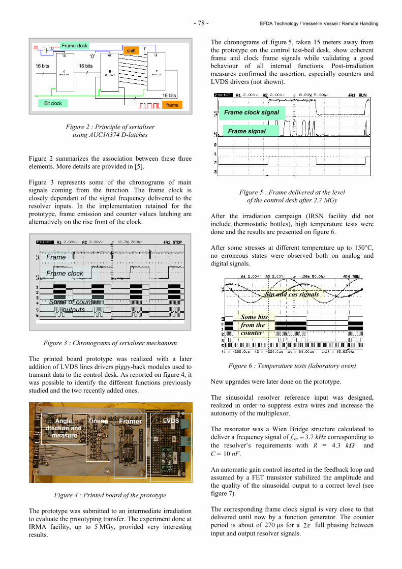
RESOLVER BRT OR RESOLVER “φ”: The only resolver retained for the future multiplexor needs Asin (ωt) and Acos (ωt) as inputs and delivers a Asin (ωt + l - φ) as output. The design of electronic functions and the global positive results of radiation campaigns of the mock-ups were detailed on [1][2][3]. To increase embedded autonomy and improve wire reduction and thus beneficiate of enhanced AUC components, some functions were redefined or added before making the printed board prototype. The serialiser necessary to deliver the frame of the digital coded value coming from the position angle conversion uses three recent AU16374 synchronized latches. A particular design reconstitutes a shift register commonly used to serialize digital.
- 78 - EFDA Technology / Vessel-In Vessel / Remote Handling
shift
frame
16 bits 16 bits
Bit clock
Frame clock
‘0’
16 bits
‘1’shift
frame
16 bits 16 bits
Bit clock
Frame clock
‘0’
16 bits
‘1’
Figure 2 : Principle of serialiser using AUC16374 D-latches
Figure 2 summarizes the association between these three elements. More details are provided in [5]. Figure 3 represents some of the chronograms of main signals coming from the function. The frame clock is closely dependant of the signal frequency delivered to the resolver inputs. In the implementation retained for the prototype, frame emission and counter values latching are alternatively on the rise front of the clock.
Figure 3 : Chronograms of serialiser mechanism The printed board prototype was realized with a later addition of LVDS lines drivers piggy-back modules used to transmit data to the control desk. As reported on figure 4, it was possible to identify the different functions previously studied and the two recently added ones.
Figure 4 : Printed board of the prototype The prototype was submitted to an intermediate irradiation to evaluate the prototyping transfer. The experiment done at IRMA facility, up to 5 MGy, provided very interesting results.
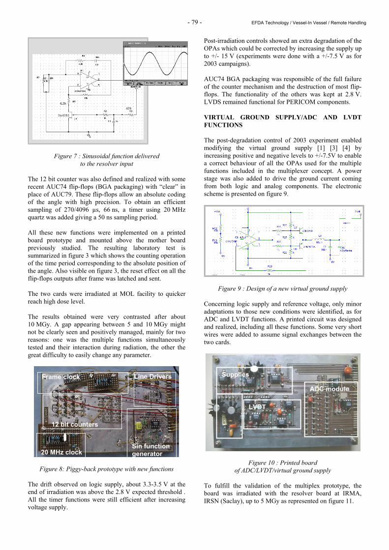
The chronograms of figure 5, taken 15 meters away from the prototype on the control test-bed desk, show coherent frame and clock frame signals while validating a good behaviour of all internal functions. Post-irradiation measures confirmed the assertion, especially counters and LVDS drivers (not shown).
Figure 5 : Frame delivered at the level of the control desk after 2.7 MGy
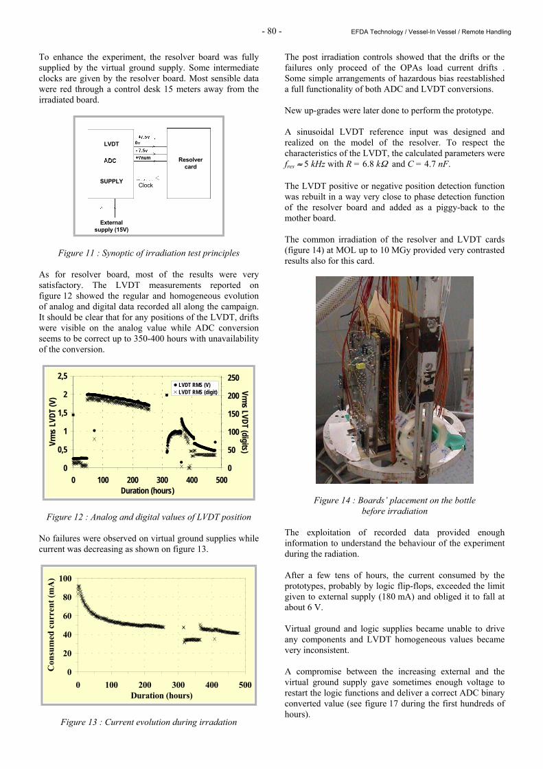
After the irradiation campaign (IRSN facility did not include thermostatic bottles), high temperature tests were done and the results are presented on figure 6. After some stresses at different temperature up to 150°C, no erroneous states were observed both on analog and digital signals.
Figure 6 : Temperature tests (laboratory oven) New upgrades were later done on the prototype. The sinusoidal resolver reference input was designed, realized in order to suppress extra wires and increase the autonomy of the multiplexor. The resonator was a Wien Bridge structure calculated to deliver a frequency signal of fres ≈ 3.7 kHz corresponding to the resolver’s requirements with R = 4.3 kΩ and C = 10 nF. An automatic gain control inserted in the feedback loop and assumed by a FET transistor stabilized the amplitude and the quality of the sinusoidal output to a correct level (see figure 7). The corresponding frame clock signal is very close to that delivered until now by a function generator. The counter period is about of 270 µs for a π2 full phasing between input and output resolver signals.
Frame
Frame clock
Some of counter outputs
Frame clock signal
Frame signal
Angle dtection and
measure
Timing Framer LVDS
Sin and cos signals
Some bits from the counter
- 79 - EFDA Technology / Vessel-In Vessel / Remote Handling
Figure 7 : Sinusoidal function delivered to the resolver input
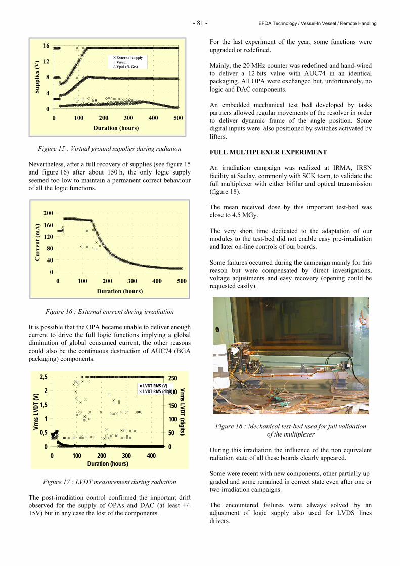
The 12 bit counter was also defined and realized with some recent AUC74 flip-flops (BGA packaging) with “clear” in place of AUC79. These flip-flops allow an absolute coding of the angle with high precision. To obtain an efficient sampling of 270/4096 µs, 66 ns, a timer using 20 MHz quartz was added giving a 50 ns sampling period. All these new functions were implemented on a printed board prototype and mounted above the mother board previously studied. The resulting laboratory test is summarized in figure 3 which shows the counting operation of the time period corresponding to the absolute position of the angle. Also visible on figure 3, the reset effect on all the flip-flops outputs after frame was latched and sent. The two cards were irradiated at MOL facility to quicker reach high dose level. The results obtained were very contrasted after about 10 MGy. A gap appearing between 5 and 10 MGy might not be clearly seen and positively managed, mainly for two reasons: one was the multiple functions simultaneously tested and their interaction during radiation, the other the great difficulty to easily change any parameter.
Figure 8: Piggy-back prototype with new functions The drift observed on logic supply, about 3.3-3.5 V at the end of irradiation was above the 2.8 V expected threshold . All the timer functions were still efficient after increasing voltage supply.
Post-irradiation controls showed an extra degradation of the OPAs which could be corrected by increasing the supply up to +/- 15 V (experiments were done with a +/-7.5 V as for 2003 campaigns). AUC74 BGA packaging was responsible of the full failure of the counter mechanism and the destruction of most flip-flops. The functionality of the others was kept at 2.8 V. LVDS remained functional for PERICOM components. VIRTUAL GROUND SUPPLY/ADC AND LVDT FUNCTIONS The post-degradation control of 2003 experiment enabled modifying the virtual ground supply [1] [3] [4] by increasing positive and negative levels to +/-7.5V to enable a correct behaviour of all the OPAs used for the multiple functions included in the multiplexer concept. A power stage was also added to drive the ground current coming from both logic and analog components. The electronic scheme is presented on figure 9.
Figure 9 : Design of a new virtual ground supply Concerning logic supply and reference voltage, only minor adaptations to those new conditions were identified, as for ADC and LVDT functions. A printed circuit was designed and realized, including all these functions. Some very short wires were added to assume signal exchanges between the two cards.
Figure 10 : Printed board of ADC/LVDT/virtual ground supply
To fulfill the validation of the multiplex prototype, the board was irradiated with the resolver board at IRMA, IRSN (Saclay), up to 5 MGy as represented on figure 11.
20 MHz clock
12 bit counters
Frame clock Line Drivers
Sin function generator
ADC module
Supplies
LVDT
- 80 - EFDA Technology / Vessel-In Vessel / Remote Handling
To enhance the experiment, the resolver board was fully supplied by the virtual ground supply. Some intermediate clocks are given by the resolver board. Most sensible data were red through a control desk 15 meters away from the irradiated board.
SUPPLY
LVDT
Resolver card
External supply (15V)
ClockSUPPLY
LVDT
Resolver card
External supply (15V)
Clock
Figure 11 : Synoptic of irradiation test principles As for resolver board, most of the results were very satisfactory. The LVDT measurements reported on figure 12 showed the regular and homogeneous evolution of analog and digital data recorded all along the campaign. It should be clear that for any positions of the LVDT, drifts were visible on the analog value while ADC conversion seems to be correct up to 350-400 hours with unavailability of the conversion.
0
0,5
1
1,5
2
2,5
0 100 200 300 400 500Duration (hours)
Vrm
s LVD
T (V
)
0
50
100
150
200
250
Vrms LVDT (digits)
LVDT RMS (V)LVDT RMS (digit)
Figure 12 : Analog and digital values of LVDT position No failures were observed on virtual ground supplies while current was decreasing as shown on figure 13.
0
20
40
60
80
100
0 100 200 300 400 500Duration (hours)
Con
sum
ed c
urre
nt (m
A)
Figure 13 : Current evolution during irradation
The post irradiation controls showed that the drifts or the failures only proceed of the OPAs load current drifts . Some simple arrangements of hazardous bias reestablished a full functionality of both ADC and LVDT conversions. New up-grades were later done to perform the prototype. A sinusoidal LVDT reference input was designed and realized on the model of the resolver. To respect the characteristics of the LVDT, the calculated parameters were fres ≈ 5 kHz with R = 6.8 kΩ and C = 4.7 nF. The LVDT positive or negative position detection function was rebuilt in a way very close to phase detection function of the resolver board and added as a piggy-back to the mother board. The common irradiation of the resolver and LVDT cards (figure 14) at MOL up to 10 MGy provided very contrasted results also for this card.
Figure 14 : Boards’ placement on the bottle before irradiation
The exploitation of recorded data provided enough information to understand the behaviour of the experiment during the radiation. After a few tens of hours, the current consumed by the prototypes, probably by logic flip-flops, exceeded the limit given to external supply (180 mA) and obliged it to fall at about 6 V. Virtual ground and logic supplies became unable to drive any components and LVDT homogeneous values became very inconsistent. A compromise between the increasing external and the virtual ground supply gave sometimes enough voltage to restart the logic functions and deliver a correct ADC binary converted value (see figure 17 during the first hundreds of hours).
- 81 - EFDA Technology / Vessel-In Vessel / Remote Handling
0
4
8
12
16
0 100 200 300 400 500Duration (hours)
Supp
lies (
V) External supply
VnumVpol (fl. Gr.)
Figure 15 : Virtual ground supplies during radiation Nevertheless, after a full recovery of supplies (see figure 15 and figure 16) after about 150 h, the only logic supply seemed too low to maintain a permanent correct behaviour of all the logic functions.
0
40
80
120
160
200
0 100 200 300 400 500Duration (hours)
Cur
rent
(mA
)
Figure 16 : External current during irradiation It is possible that the OPA became unable to deliver enough current to drive the full logic functions implying a global diminution of global consumed current, the other reasons could also be the continuous destruction of AUC74 (BGA packaging) components.
0
0,5
1
1,5
2
2,5
0 100 200 300 400Duration (hours)
Vrm
s LVD
T (V
)
0
50
100
150
200
250
Vrms LVDT (digits)
LVDT RMS (V)LVDT RMS (digit)
Figure 17 : LVDT measurement during radiation The post-irradiation control confirmed the important drift observed for the supply of OPAs and DAC (at least +/-15V) but in any case the lost of the components.
For the last experiment of the year, some functions were upgraded or redefined. Mainly, the 20 MHz counter was redefined and hand-wired to deliver a 12 bits value with AUC74 in an identical packaging. All OPA were exchanged but, unfortunately, no logic and DAC components. An embedded mechanical test bed developed by tasks partners allowed regular movements of the resolver in order to deliver dynamic frame of the angle position. Some digital inputs were also positioned by switches activated by lifters. FULL MULTIPLEXER EXPERIMENT An irradiation campaign was realized at IRMA, IRSN facility at Saclay, commonly with SCK team, to validate the full multiplexer with either bifilar and optical transmission (figure 18). The mean received dose by this important test-bed was close to 4.5 MGy. The very short time dedicated to the adaptation of our modules to the test-bed did not enable easy pre-irradiation and later on-line controls of our boards. Some failures occurred during the campaign mainly for this reason but were compensated by direct investigations, voltage adjustments and easy recovery (opening could be requested easily).
Figure 18 : Mechanical test-bed used for full validation of the multiplexer
During this irradiation the influence of the non equivalent radiation state of all these boards clearly appeared. Some were recent with new components, other partially up-graded and some remained in correct state even after one or two irradiation campaigns. The encountered failures were always solved by an adjustment of logic supply also used for LVDS lines drivers.
- 82 - EFDA Technology / Vessel-In Vessel / Remote Handling
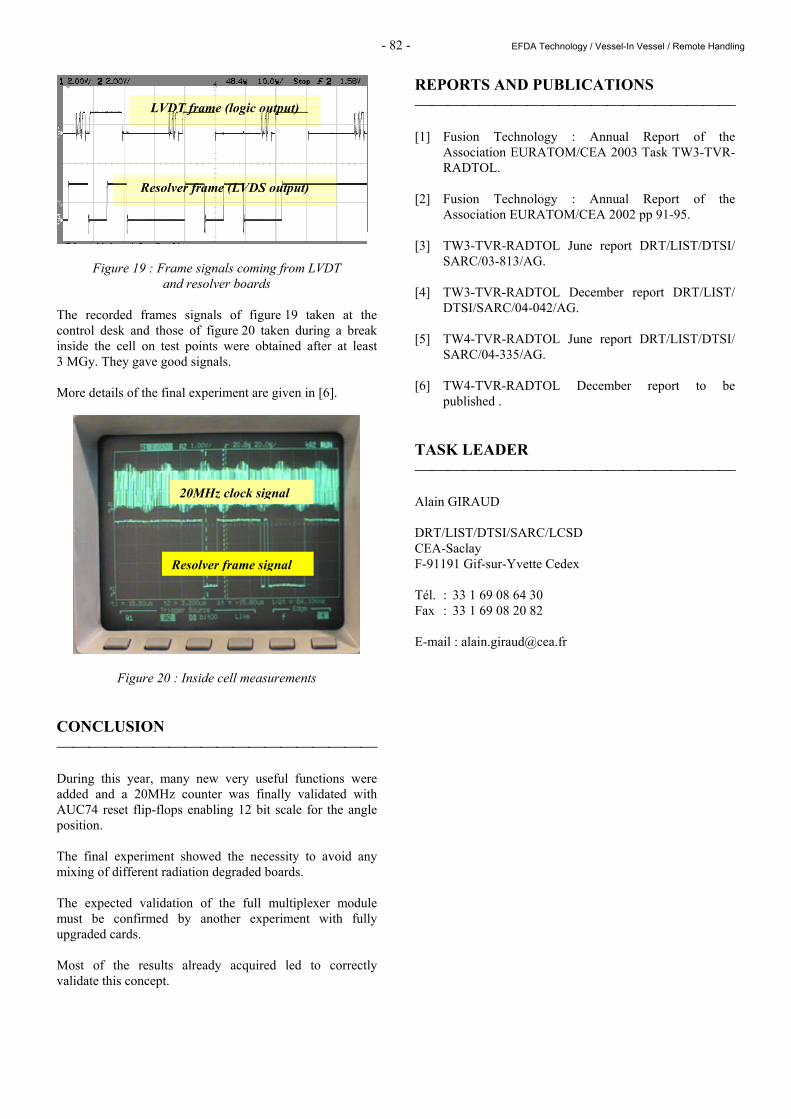
Figure 19 : Frame signals coming from LVDT and resolver boards
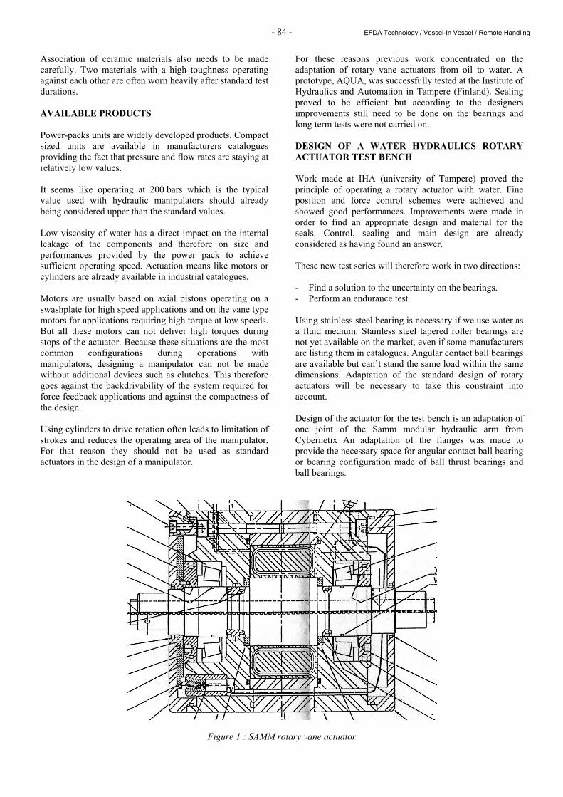
The recorded frames signals of figure 19 taken at the control desk and those of figure 20 taken during a break inside the cell on test points were obtained after at least 3 MGy. They gave good signals. More details of the final experiment are given in [6].
Figure 20 : Inside cell measurements CONCLUSION During this year, many new very useful functions were added and a 20MHz counter was finally validated with AUC74 reset flip-flops enabling 12 bit scale for the angle position. The final experiment showed the necessity to avoid any mixing of different radiation degraded boards. The expected validation of the full multiplexer module must be confirmed by another experiment with fully upgraded cards. Most of the results already acquired led to correctly validate this concept.
REPORTS AND PUBLICATIONS [1] Fusion Technology : Annual Report of the
Association EURATOM/CEA 2003 Task TW3-TVR-RADTOL.
[2] Fusion Technology : Annual Report of the
Association EURATOM/CEA 2002 pp 91-95. [3] TW3-TVR-RADTOL June report DRT/LIST/DTSI/
SARC/03-813/AG. [4] TW3-TVR-RADTOL December report DRT/LIST/
DTSI/SARC/04-042/AG. [5] TW4-TVR-RADTOL June report DRT/LIST/DTSI/
SARC/04-335/AG. [6] TW4-TVR-RADTOL December report to be
published . TASK LEADER Alain GIRAUD DRT/LIST/DTSI/SARC/LCSD CEA-Saclay F-91191 Gif-sur-Yvette Cedex Tél. : 33 1 69 08 64 30 Fax : 33 1 69 08 20 82 E-mail : [email protected]
LVDT frame (logic output)
Resolver frame (LVDS output)
20MHz clock signal
Resolver frame signal

- 83 - EFDA Technology / Vessel-In Vessel / Remote Handling
TW4-TVR-WHMAN Task Title: DEVELOPMENT OF A WATER HYDRAULIC MANIPULATOR INTRODUCTION Due to the high level of radiations, the nominal maintenance in ITER will be carried out with help of robotic means. In reduced volumes, hydraulic applications can provide powerful actuators. Therefore, they become an interesting technology to design a heavy duty manipulator for operations in space constrained areas. Operating in a fusion reactor requires a cleanliness level that oil hydraulic cannot ensure. Pure water hydraulics therefore proposes a good alternative and developments are today focusing on that direction. Although basic hydraulic elements like pumps, valves, filters running with pure water are already available on the market, actuators are not so many. Linear actuators are already available on shelf but compact rotary actuators are still missing. Although some R&D developments are providing powerful actuators in compact design, the size of the existing industrial products would make a big and heavy component. The design of the actuator was sometimes quickly adapted to water without real endurance tests and their reliability steel needs to be tested. A reflection was carried out to propose an actuator design compatible with ITER’s specific requirements. 2004 ACTIVITIES USING WATER AS A FLUID MEDIUM Compared to oil, water has the following drawbacks: - Has a low viscosity. - Has a higher density. - Creates erosion. - Corrodes the internal surfaces. - Has a high vapour pressure. - Has poor lubricant properties. - Is a living environment. - Reduced operating temperature range. Although water hydraulics is not new, the number of industrial and therefore of industrial products available on the market can still be considered as confidential compared to oil hydraulics and lots of work is still done in research laboratories. According to all the publications, material selection and build quality are essential parameters to consider when designing water hydraulics systems.
Water has a viscosity that is generally one thirtieth that of hydraulic oil. The effects are a higher acceleration rate, faster flow velocities and greater energy creating altogether a bigger potential of destruction. Low viscosity also gives the ability to go through smaller cracks. High vapour pressure creates systems highly susceptible to cavitation which leads to erosion of internal surfaces. Effects of water’s low viscosity on the design are most of the time solved by machining with tighter part tolerances. For pure tape water hydraulics products, clearances are now typically found between 2 µm and 10 µm. General rules are talking about clearance order of a third or less compared to oil hydraulics. Typical films thicknesses for hydrodynamic lubrication are of 0.1 µm for water compared to 10 µm for oil. Ten times less is needed for both cases in elasto-hydrodynamic regime. In fact the film thickness becomes unacceptable with water because the build quality can’t provide such accuracy. Therefore, roller bearings and all classical rolling elements can not be used with the classical specifications related to lifetime or load capacity in water applications, even if they are made of corrosion resistant materials. Bearings with plastic bushing are seen in many applications where the loads are low but the most commons solution is a combination of PEEK and stainless steel. They are generally limited to systems operating at pressures lower than 160 bars. Material choice is probably one of the most difficult aspects in the design of water hydraulics components. Stainless steel is widely used to fight against corrosion. Pistons, cylinder blocks, valve plates are typical part now made with that material while housings are using more an more cast bronze. Due to poor lubrication, it is assumed that there will be a relatively high coefficient of friction and that surface wear will take place. Because of corrosion stainless steel should be used for all the power transmission parts, but friction of stainless steel with other materials is usually high. Metal-metal contact seems out of question and all publications agreed on the fact that one of the rubbing surfaces must be non-metallic. Leakage and erosion problems are sometimes solved by manufacturers through the use of new ceramic materials. Among them: aluminum oxides and Zirconias.
- 84 - EFDA Technology / Vessel-In Vessel / Remote Handling
Association of ceramic materials also needs to be made carefully. Two materials with a high toughness operating against each other are often worn heavily after standard test durations. AVAILABLE PRODUCTS Power-packs units are widely developed products. Compact sized units are available in manufacturers catalogues providing the fact that pressure and flow rates are staying at relatively low values. It seems like operating at 200 bars which is the typical value used with hydraulic manipulators should already being considered upper than the standard values. Low viscosity of water has a direct impact on the internal leakage of the components and therefore on size and performances provided by the power pack to achieve sufficient operating speed. Actuation means like motors or cylinders are already available in industrial catalogues. Motors are usually based on axial pistons operating on a swashplate for high speed applications and on the vane type motors for applications requiring high torque at low speeds. But all these motors can not deliver high torques during stops of the actuator. Because these situations are the most common configurations during operations with manipulators, designing a manipulator can not be made without additional devices such as clutches. This therefore goes against the backdrivability of the system required for force feedback applications and against the compactness of the design. Using cylinders to drive rotation often leads to limitation of strokes and reduces the operating area of the manipulator. For that reason they should not be used as standard actuators in the design of a manipulator.
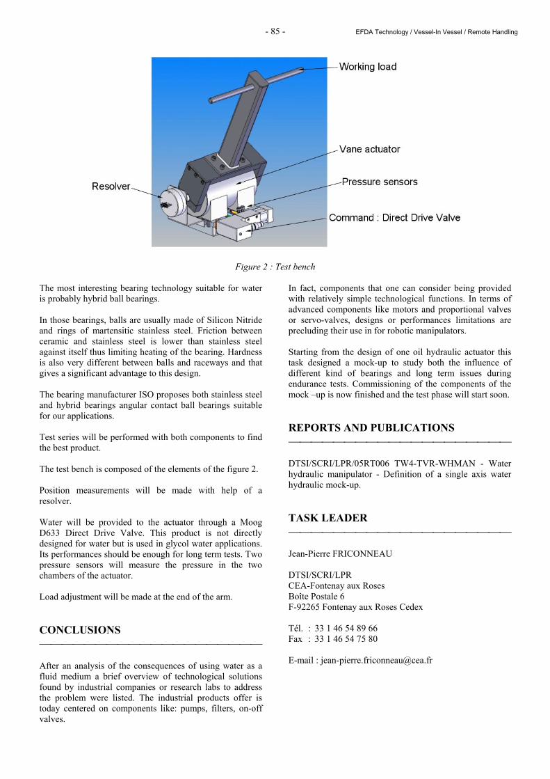
For these reasons previous work concentrated on the adaptation of rotary vane actuators from oil to water. A prototype, AQUA, was successfully tested at the Institute of Hydraulics and Automation in Tampere (Finland). Sealing proved to be efficient but according to the designers improvements still need to be done on the bearings and long term tests were not carried on. DESIGN OF A WATER HYDRAULICS ROTARY ACTUATOR TEST BENCH Work made at IHA (university of Tampere) proved the principle of operating a rotary actuator with water. Fine position and force control schemes were achieved and showed good performances. Improvements were made in order to find an appropriate design and material for the seals. Control, sealing and main design are already considered as having found an answer. These new test series will therefore work in two directions: - Find a solution to the uncertainty on the bearings. - Perform an endurance test. Using stainless steel bearing is necessary if we use water as a fluid medium. Stainless steel tapered roller bearings are not yet available on the market, even if some manufacturers are listing them in catalogues. Angular contact ball bearings are available but can’t stand the same load within the same dimensions. Adaptation of the standard design of rotary actuators will be necessary to take this constraint into account. Design of the actuator for the test bench is an adaptation of one joint of the Samm modular hydraulic arm from Cybernetix An adaptation of the flanges was made to provide the necessary space for angular contact ball bearing or bearing configuration made of ball thrust bearings and ball bearings.
Figure 1 : SAMM rotary vane actuator
- 85 - EFDA Technology / Vessel-In Vessel / Remote Handling
Figure 2 : Test bench The most interesting bearing technology suitable for water is probably hybrid ball bearings. In those bearings, balls are usually made of Silicon Nitride and rings of martensitic stainless steel. Friction between ceramic and stainless steel is lower than stainless steel against itself thus limiting heating of the bearing. Hardness is also very different between balls and raceways and that gives a significant advantage to this design. The bearing manufacturer ISO proposes both stainless steel and hybrid bearings angular contact ball bearings suitable for our applications. Test series will be performed with both components to find the best product. The test bench is composed of the elements of the figure 2. Position measurements will be made with help of a resolver. Water will be provided to the actuator through a Moog D633 Direct Drive Valve. This product is not directly designed for water but is used in glycol water applications. Its performances should be enough for long term tests. Two pressure sensors will measure the pressure in the two chambers of the actuator. Load adjustment will be made at the end of the arm. CONCLUSIONS After an analysis of the consequences of using water as a fluid medium a brief overview of technological solutions found by industrial companies or research labs to address the problem were listed. The industrial products offer is today centered on components like: pumps, filters, on-off valves.
In fact, components that one can consider being provided with relatively simple technological functions. In terms of advanced components like motors and proportional valves or servo-valves, designs or performances limitations are precluding their use in for robotic manipulators. Starting from the design of one oil hydraulic actuator this task designed a mock-up to study both the influence of different kind of bearings and long term issues during endurance tests. Commissioning of the components of the mock –up is now finished and the test phase will start soon. REPORTS AND PUBLICATIONS DTSI/SCRI/LPR/05RT006 TW4-TVR-WHMAN - Water hydraulic manipulator - Definition of a single axis water hydraulic mock-up. TASK LEADER Jean-Pierre FRICONNEAU DTSI/SCRI/LPR CEA-Fontenay aux Roses Boîte Postale 6 F-92265 Fontenay aux Roses Cedex Tél. : 33 1 46 54 89 66 Fax : 33 1 46 54 75 80 E-mail : [email protected]

- 86 - EFDA Technology / Vessel-In Vessel / Remote Handling