phase 1 of articulated arm 6-axis robot - csu, chico€¢ design, build, and test a prototype...
TRANSCRIPT
Phase 1 of Articulated Arm 6-Axis Robot

Cory NannMechanical
Kris MagriMechatronic
Cole ChristensenMechatronic
Michael TominMechanical
Joshua DugoMechatronic
Faculty Advisor: Ramesh Varahamurti
Project Sponsor: Micro-Vu
Project Team Members
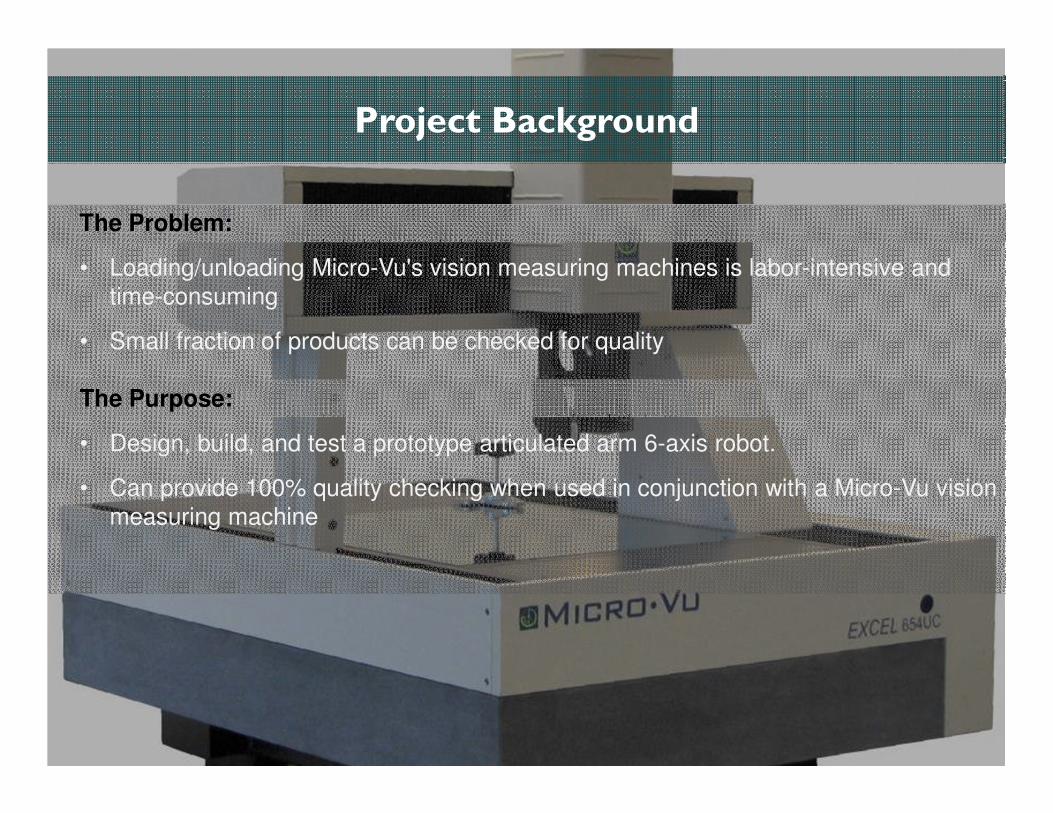
Project Background
The Problem:
• Loading/unloading Micro-Vu's vision measuring machines is labor-intensive and
time-consuming
• Small fraction of products can be checked for quality
The Purpose:
• Design, build, and test a prototype articulated arm 6-axis robot.
• Can provide 100% quality checking when used in conjunction with a Micro-Vu vision
measuring machine
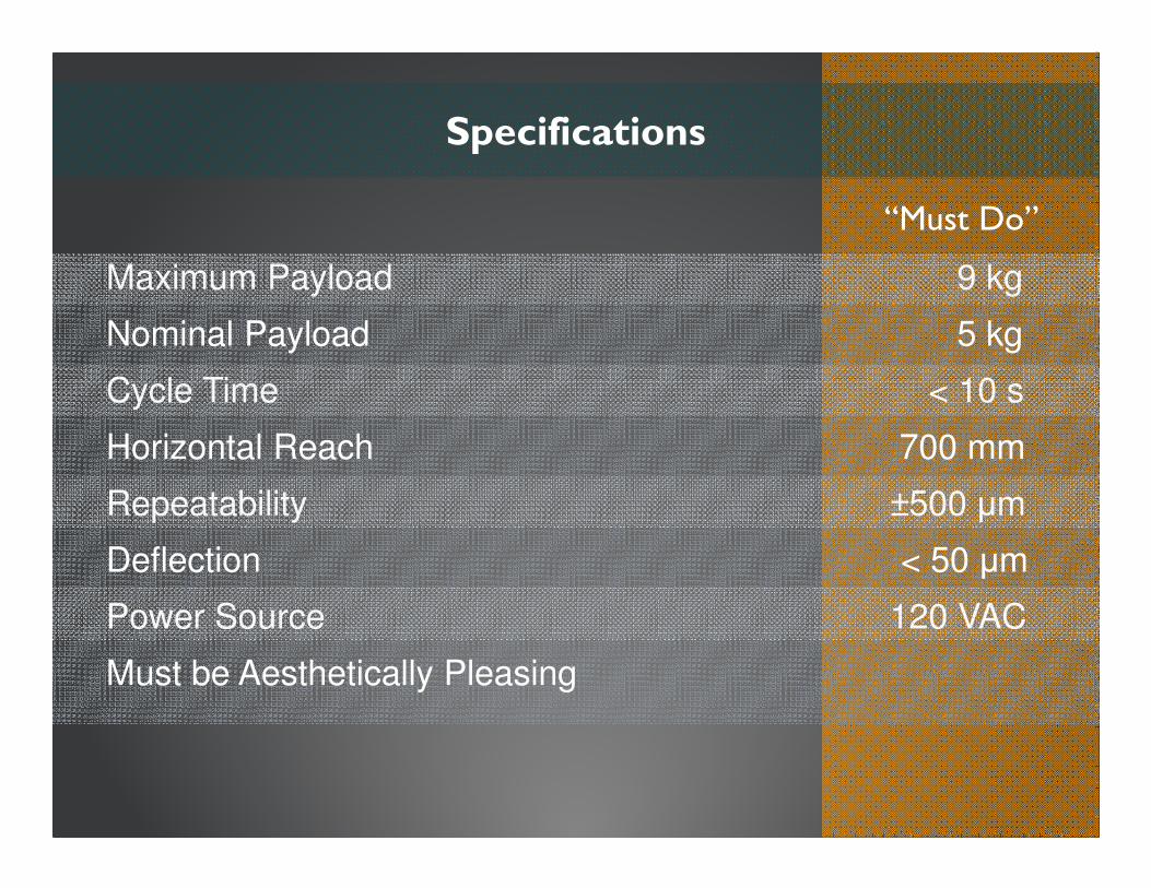
Maximum Payload 9 kg
Nominal Payload 5 kg
Cycle Time < 10 s
Horizontal Reach 700 mm
Repeatability ±500 µm
Deflection < 50 µm
Power Source 120 VAC
Must be Aesthetically Pleasing
Specifications
“Must Do”
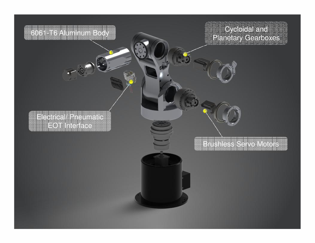
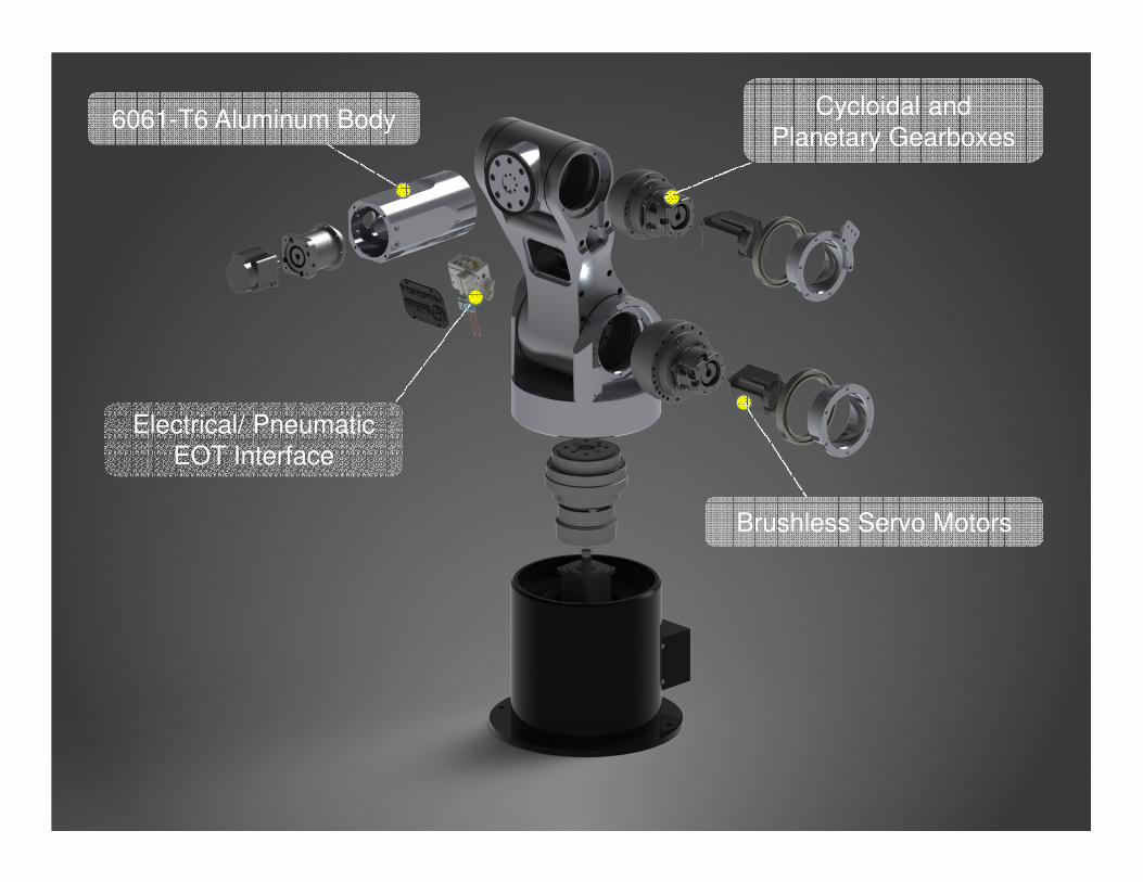
Cycloidal and
Planetary Gearboxes
Brushless Servo Motors
6061-T6 Aluminum Body
Electrical/ Pneumatic
EOT Interface

Robotic Arm Design and Fabrication
• Designed In Solidworks
• Machined from 6061-T6 Aluminum
• Complex Geometry Performed on
5 Axis CNC by Micro-Vu (Thanks!)
Cycloidal and
Planetary Gearboxes
Brushless Servo Motors
6061-T6 Aluminum Body
Electrical/ Pneumatic
EOT Interface

Gearbox Selection
Axis Gear ratioBacklash (arc-
min)
Peak Torque of
motor (Nm)
Peak Torque at
Output (Nm)
Speed of motor
(rpm)
Output Speed of
Load (rpm)
1 57:1 1 5 80.6 1470 25.8
2 105:1 1 3.8 159.2 802 7.6
3 105:1 1 1.9 165.2 2126 20.3
4 25:1 16 0.9 4.4 3000 120
Axis
Calculated
Moment
Load [Nm]
Allowable
Moment Load
[Nm]
Thrust
Load [N]
Factor of
Safety
1 135 882 400 6.5
2 23 882 150 38.3
3 14 195 250 13.9
Nabtesco Gearhead Bearing Loading
Axis
Allowable
Radial Load
[N]
Allowable
Axial Load [N]
Calculated
Radial Load
[N]
Calculated
Axial Load
[N]
4 550 1200 530 370
Neugart Gearhead Bearing Loading

Cycloidal and
Planetary Gearboxes
Brushless Servo Motors
6061-T6 Aluminum Body
Electrical/ Pneumatic
EOT Interface
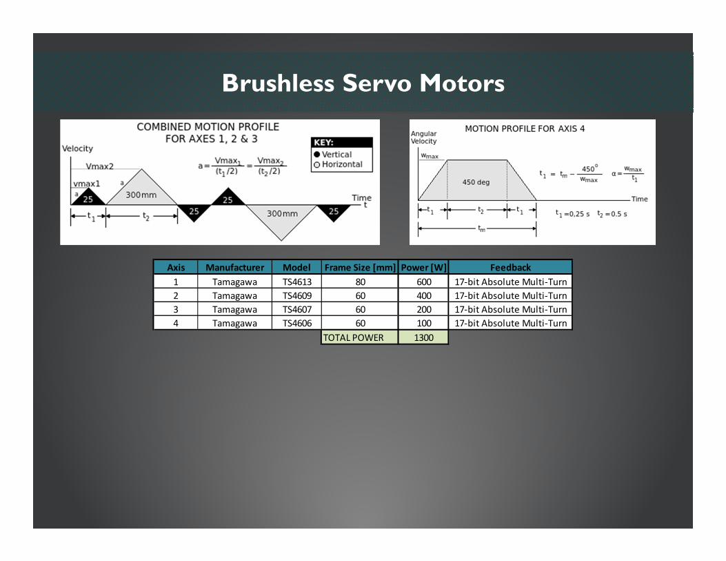
Brushless Servo Motors
Axis Manufacturer Model Frame Size [mm] Power [W] Feedback
1 Tamagawa TS4613 80 600 17-bit Absolute Multi-Turn
2 Tamagawa TS4609 60 400 17-bit Absolute Multi-Turn
3 Tamagawa TS4607 60 200 17-bit Absolute Multi-Turn
4 Tamagawa TS4606 60 100 17-bit Absolute Multi-Turn
TOTAL POWER 1300

Cycloidal and
Planetary Gearboxes
Brushless Servo Motors
6061-T6 Aluminum Body
Electrical/ Pneumatic
EOT Interface
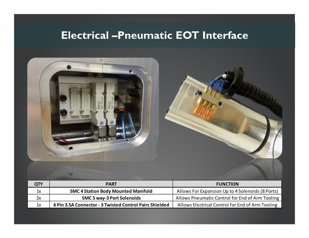
Electrical –Pneumatic EOT Interface
QTY PART FUNCTION
1x SMC 4 Station Body Mounted Manifold Allows For Expansion Up to 4 Solenoids (8 Ports)
2x SMC 5 way-3 Port Solenoids Allows Pneumatic Control for End of Arm Tooling
1x 6 Pin 3.5A Connector - 3 Twisted Control Pairs Shielded Allows Electrical Control for End of Arm Tooling
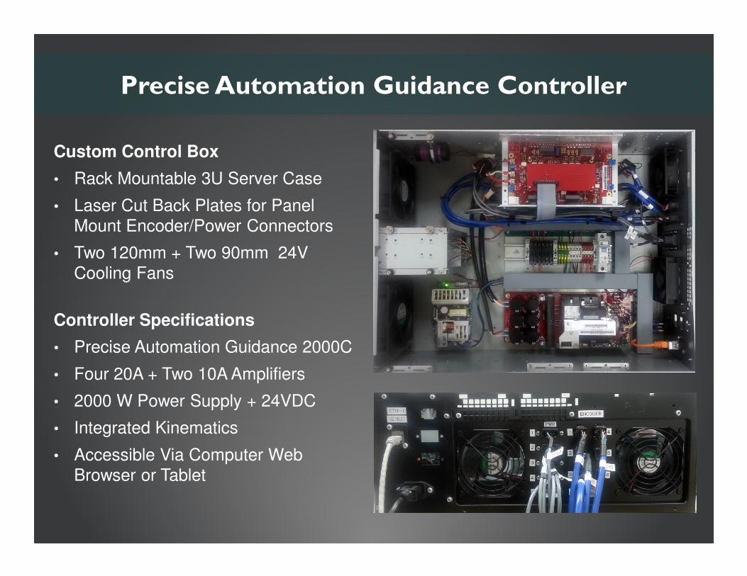
Precise Automation Guidance Controller
Controller Specifications
• Precise Automation Guidance 2000C
• Four 20A + Two 10A Amplifiers
• 2000 W Power Supply + 24VDC
• Integrated Kinematics
• Accessible Via Computer Web
Browser or Tablet
Custom Control Box
• Rack Mountable 3U Server Case
• Laser Cut Back Plates for Panel
Mount Encoder/Power Connectors
• Two 120mm + Two 90mm 24V
Cooling Fans
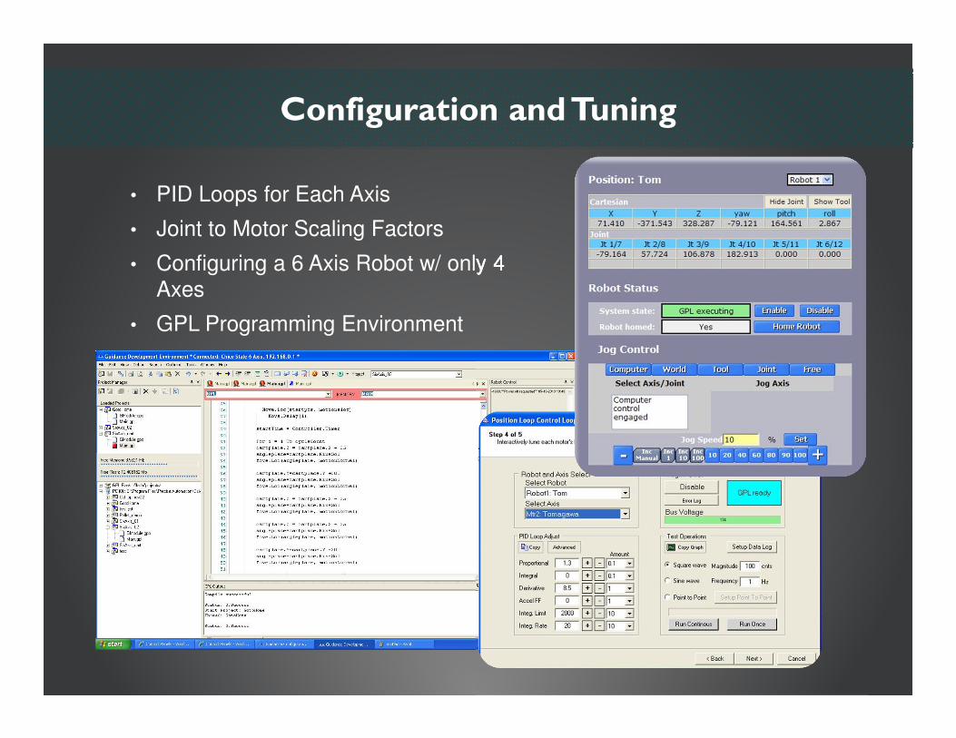
Configuration and Tuning
• PID Loops for Each Axis
• Joint to Motor Scaling Factors
• Configuring a 6 Axis Robot w/ only 4
Axes
• GPL Programming Environment
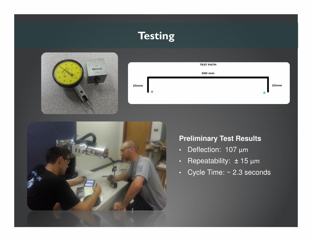
Testing
Preliminary Test Results
• Deflection: 107 μm
• Repeatability: ± 15 μm
• Cycle Time: ~ 2.3 seconds

Cost of Components: $25,316Cost of Man-Hours (1246 Hrs): $50,190
GRAND TOTAL: $75,506
Budget
Controller $6,350
Labor$50,190
Pneumatics $266
Servo Motors $2,340
Gearheads$10,135
Electrical Components & Wiring$1,380
Material & Hardware$4,845
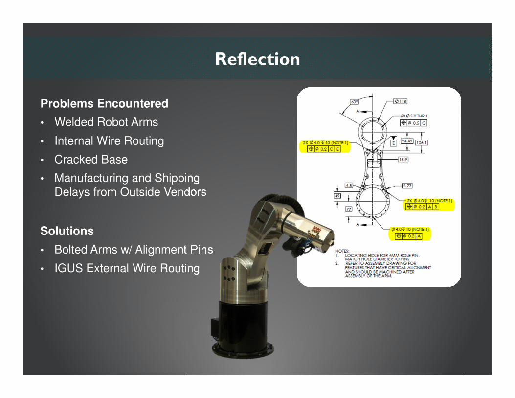
Reflection
Problems Encountered
• Welded Robot Arms
• Internal Wire Routing
• Cracked Base
• Manufacturing and Shipping
Delays from Outside Vendors
Solutions
• Bolted Arms w/ Alignment Pins
• IGUS External Wire Routing
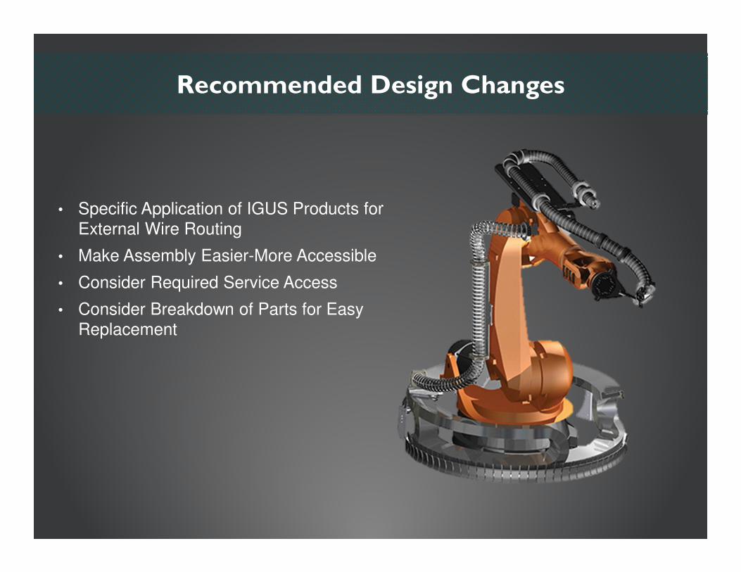
Recommended Design Changes
• Specific Application of IGUS Products for
External Wire Routing
• Make Assembly Easier-More Accessible
• Consider Required Service Access
• Consider Breakdown of Parts for Easy
Replacement
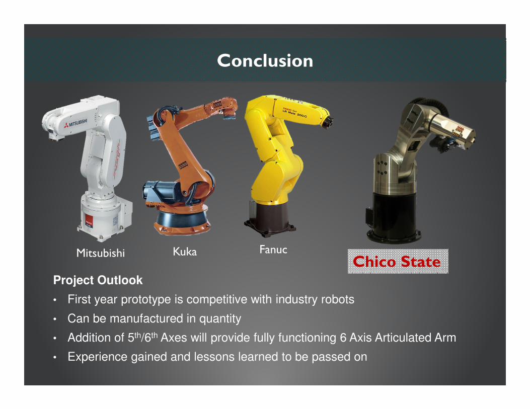
Conclusion
Mitsubishi Kuka FanucChico State
Project Outlook
• First year prototype is competitive with industry robots
• Can be manufactured in quantity
• Addition of 5th/6th Axes will provide fully functioning 6 Axis Articulated Arm
• Experience gained and lessons learned to be passed on

Questions
Thanks to our Sponsor, Advisor, and all other faculty and students who helped our project succeed.