dhp install vmbma202 en
TRANSCRIPT

8/3/2019 Dhp Install Vmbma202 En
http://slidepdf.com/reader/full/dhp-install-vmbma202-en 1/96
VMBMA202
Installation and Service
instructions
DHP-H, DHP-C, DHP-L,
DHP-A, DHP-AL

8/3/2019 Dhp Install Vmbma202 En
http://slidepdf.com/reader/full/dhp-install-vmbma202-en 2/96
2 VMBMA202

8/3/2019 Dhp Install Vmbma202 En
http://slidepdf.com/reader/full/dhp-install-vmbma202-en 3/96
3VMBMA202
ContentsInstallation instructions ................... 5
1 Important information/Safety regulations . . . . . . . . . . . . . . . . . . 51.1 Refrigerant . . . . . . . . . . . . . . . . . . . . . . . . . . . . . . . . . . . . . . . . . . . . . . . . . . . . . . . 51.2 Electrical connection . . . . . . . . . . . . . . . . . . . . . . . . . . . . . . . . . . . . . . . . . . . . . 51.3 Commissioning. . . . . . . . . . . . . . . . . . . . . . . . . . . . . . . . . . . . . . . . . . . . . . . . . . . 5
2 Heat pump information . . . . . . . . . . . . . . . . . . . . . . . . . . . . . . . . . . . . 6
2.1 DHP-H . . . . . . . . . . . . . . . . . . . . . . . . . . . . . . . . . . . . . . . . . . . . . . . . . . . . . . . . . . . 62.2 DHP-C. . . . . . . . . . . . . . . . . . . . . . . . . . . . . . . . . . . . . . . . . . . . . . . . . . . . . . . . . . . . 82.3 DHP-L. . . . . . . . . . . . . . . . . . . . . . . . . . . . . . . . . . . . . . . . . . . . . . . . . . . . . . . . . . . 102.4 DHP-A. . . . . . . . . . . . . . . . . . . . . . . . . . . . . . . . . . . . . . . . . . . . . . . . . . . . . . . . . . . 122.5 DHP-AL . . . . . . . . . . . . . . . . . . . . . . . . . . . . . . . . . . . . . . . . . . . . . . . . . . . . . . . . . 142.6 Package contents. . . . . . . . . . . . . . . . . . . . . . . . . . . . . . . . . . . . . . . . . . . . . . . . 162.7 Heat pump control panel . . . . . . . . . . . . . . . . . . . . . . . . . . . . . . . . . . . . . . . . 172.8 Transporting the heat pump. . . . . . . . . . . . . . . . . . . . . . . . . . . . . . . . . . . . . 172.9 Space requirement . . . . . . . . . . . . . . . . . . . . . . . . . . . . . . . . . . . . . . . . . . . . . . 172.10 Recommended location . . . . . . . . . . . . . . . . . . . . . . . . . . . . . . . . . . . . . . . . . 172.11 Space requirement, outdoor unit, DHP-A, -AL. . . . . . . . . . . . . . . . . . . . . 182.12 Recommended location of outdoor unit, DHP-A, -AL . . . . . . . . . . . . . 18
3 Drilling holes for brine lines . . . . . . . . . . . . . . . . . . . . . . . . . . . . . . . 18
4 Separating the heat pump . . . . . . . . . . . . . . . . . . . . . . . . . . . . . . . . 19
5 Unpacking and installation . . . . . . . . . . . . . . . . . . . . . . . . . . . . . . . . 205.1 Setting up. . . . . . . . . . . . . . . . . . . . . . . . . . . . . . . . . . . . . . . . . . . . . . . . . . . . . . . 205.2 Removing the front cover. . . . . . . . . . . . . . . . . . . . . . . . . . . . . . . . . . . . . . . . 205.3 Unpacking and installing the outdoor unit . . . . . . . . . . . . . . . . . . . . . . . 20
6 Piping installation . . . . . . . . . . . . . . . . . . . . . . . . . . . . . . . . . . . . . . . . 226.1 VL system . . . . . . . . . . . . . . . . . . . . . . . . . . . . . . . . . . . . . . . . . . . . . . . . . . . . . . . 226.2 D system: DHP-L. . . . . . . . . . . . . . . . . . . . . . . . . . . . . . . . . . . . . . . . . . . . . . . . . 246.3 VLD system: DHP-A, -AL. . . . . . . . . . . . . . . . . . . . . . . . . . . . . . . . . . . . . . . . . . 246.4 Safety valves . . . . . . . . . . . . . . . . . . . . . . . . . . . . . . . . . . . . . . . . . . . . . . . . . . . . 256.5 Connecting cold and hot water pipes . . . . . . . . . . . . . . . . . . . . . . . . . . . . 256.6 Connecting the heating system supply and return lines . . . . . . . . . . 256.7 Filling the water heater and heating system. . . . . . . . . . . . . . . . . . . . . . 266.8 Bleeding the heating system. . . . . . . . . . . . . . . . . . . . . . . . . . . . . . . . . . . . . 26
7 Electrical Installation . . . . . . . . . . . . . . . . . . . . . . . . . . . . . . . . . . . . . 267.1 Connect power supply, 400V 3N . . . . . . . . . . . . . . . . . . . . . . . . . . . . . . . . . 277.2 Connect power supply, 230V 1N SP . . . . . . . . . . . . . . . . . . . . . . . . . . . . . . 27
7.3 Position and connect outdoor sensors . . . . . . . . . . . . . . . . . . . . . . . . . . . 277.4 Changing the language in the control computer . . . . . . . . . . . . . . . . . 277.5 Resetting to system D or VLD . . . . . . . . . . . . . . . . . . . . . . . . . . . . . . . . . . . . 287.6 Changing the number of auxiliary heating power stages . . . . . . . . . 287.7 Connect outdoor unit, DHP-A, -AL. . . . . . . . . . . . . . . . . . . . . . . . . . . . . . . . 287.8 Connect defrost sensor, DHP-A, -AL . . . . . . . . . . . . . . . . . . . . . . . . . . . . . . 28
8 Brine installation . . . . . . . . . . . . . . . . . . . . . . . . . . . . . . . . . . . . . . . . . 298.1 Heat sources . . . . . . . . . . . . . . . . . . . . . . . . . . . . . . . . . . . . . . . . . . . . . . . . . . . . 298.2 Information collector pipe . . . . . . . . . . . . . . . . . . . . . . . . . . . . . . . . . . . . . . . 308.3 Connection to outdoor unit. . . . . . . . . . . . . . . . . . . . . . . . . . . . . . . . . . . . . . 308.4 Connection of several brine coils. . . . . . . . . . . . . . . . . . . . . . . . . . . . . . . . . 308.5 Connection diagram. . . . . . . . . . . . . . . . . . . . . . . . . . . . . . . . . . . . . . . . . . . . . 318.6 Installing brine lines . . . . . . . . . . . . . . . . . . . . . . . . . . . . . . . . . . . . . . . . . . . . . 328.7 Filling the brine system . . . . . . . . . . . . . . . . . . . . . . . . . . . . . . . . . . . . . . . . . . 328.8 Bleeding the brine circuit . . . . . . . . . . . . . . . . . . . . . . . . . . . . . . . . . . . . . . . . 338.9 Vent outdoor unit, DHP-A, -AL . . . . . . . . . . . . . . . . . . . . . . . . . . . . . . . . . . . 33
9 Installing accessories/additional functions . . . . . . . . . . . . . . . . . 349.1 Room temperature sensor . . . . . . . . . . . . . . . . . . . . . . . . . . . . . . . . . . . . . . . 349.2 EVU function . . . . . . . . . . . . . . . . . . . . . . . . . . . . . . . . . . . . . . . . . . . . . . . . . . . . 349.3 Tariff control. . . . . . . . . . . . . . . . . . . . . . . . . . . . . . . . . . . . . . . . . . . . . . . . . . . . . 349.4 Flow switch/level switch . . . . . . . . . . . . . . . . . . . . . . . . . . . . . . . . . . . . . . . . . 349.5 Higher hot water temperature . . . . . . . . . . . . . . . . . . . . . . . . . . . . . . . . . . . 34
10 Start up . . . . . . . . . . . . . . . . . . . . . . . . . . . . . . . . . . . . . . . . . . . . . . . . . . 3510.1 Installation checklist . . . . . . . . . . . . . . . . . . . . . . . . . . . . . . . . . . . . . . . . . . . . . 3510.2 Manual test . . . . . . . . . . . . . . . . . . . . . . . . . . . . . . . . . . . . . . . . . . . . . . . . . . . . . 3510.3 Commissioning. . . . . . . . . . . . . . . . . . . . . . . . . . . . . . . . . . . . . . . . . . . . . . . . . . 3610.4 Installing the front cover . . . . . . . . . . . . . . . . . . . . . . . . . . . . . . . . . . . . . . . . 3610.5 After start up . . . . . . . . . . . . . . . . . . . . . . . . . . . . . . . . . . . . . . . . . . . . . . . . . . . . 36
11 Customer information . . . . . . . . . . . . . . . . . . . . . . . . . . . . . . . . . . . . 37
Service instructions .......................... 38
12 The heat pump . . . . . . . . . . . . . . . . . . . . . . . . . . . . . . . . . . . . . . . . . . . 3812.1 Function description. . . . . . . . . . . . . . . . . . . . . . . . . . . . . . . . . . . . . . . . . . . . . 3812.2 Components . . . . . . . . . . . . . . . . . . . . . . . . . . . . . . . . . . . . . . . . . . . . . . . . . . . . 3812.3 Outdoor unit and defroster function, DHP-A, -AL . . . . . . . . . . . . . . . . . 3912.4 Passive cooling function, DHP-C . . . . . . . . . . . . . . . . . . . . . . . . . . . . . . . . . 4012.5 Auxiliary heating, DHP-H, -L, -C . . . . . . . . . . . . . . . . . . . . . . . . . . . . . . . . . . 4012.6 Auxiliary heating DHP-A, -AL. . . . . . . . . . . . . . . . . . . . . . . . . . . . . . . . . . . . . 4012.7 Water heater, DHP-H, -C. . . . . . . . . . . . . . . . . . . . . . . . . . . . . . . . . . . . . . . . . . 4112.8 Water heater, DHP-A, -AL. . . . . . . . . . . . . . . . . . . . . . . . . . . . . . . . . . . . . . . . . 4112.9 Important parameters . . . . . . . . . . . . . . . . . . . . . . . . . . . . . . . . . . . . . . . . . . . 42
13 Control computer. . . . . . . . . . . . . . . . . . . . . . . . . . . . . . . . . . . . . . . . . 4713.1 Function description. . . . . . . . . . . . . . . . . . . . . . . . . . . . . . . . . . . . . . . . . . . . . 4713.2 Display. . . . . . . . . . . . . . . . . . . . . . . . . . . . . . . . . . . . . . . . . . . . . . . . . . . . . . . . . . 48
14 Menus . . . . . . . . . . . . . . . . . . . . . . . . . . . . . . . . . . . . . . . . . . . . . . . . . . . 5014.1 Main menu INFORMATION . . . . . . . . . . . . . . . . . . . . . . . . . . . . . . . . . . . . . . . 5014.2 Main menu SERVICE . . . . . . . . . . . . . . . . . . . . . . . . . . . . . . . . . . . . . . . . . . . . . 53
15 O perating conditions . . . . . . . . . . . . . . . . . . . . . . . . . . . . . . . . . . . . . 5815.1 Starting heat production . . . . . . . . . . . . . . . . . . . . . . . . . . . . . . . . . . . . . . . . 5815.2 Stopping heat production . . . . . . . . . . . . . . . . . . . . . . . . . . . . . . . . . . . . . . . 5815.3 Starting hot water production . . . . . . . . . . . . . . . . . . . . . . . . . . . . . . . . . . . 5815.4 Stopping hot water production . . . . . . . . . . . . . . . . . . . . . . . . . . . . . . . . . . 58
16 Troubleshooting . . . . . . . . . . . . . . . . . . . . . . . . . . . . . . . . . . . . . . . . . . 6016.1 Alarm list. . . . . . . . . . . . . . . . . . . . . . . . . . . . . . . . . . . . . . . . . . . . . . . . . . . . . . . . 6016.2 Measurement points. . . . . . . . . . . . . . . . . . . . . . . . . . . . . . . . . . . . . . . . . . . . . 6016.3 Check points . . . . . . . . . . . . . . . . . . . . . . . . . . . . . . . . . . . . . . . . . . . . . . . . . . . . 6116.4 Operational problems . . . . . . . . . . . . . . . . . . . . . . . . . . . . . . . . . . . . . . . . . . . 62
17 Technical data . . . . . . . . . . . . . . . . . . . . . . . . . . . . . . . . . . . . . . . . . . . . 82
Appendix. . . . . . . . . . . . . . . . . . . . . . . . . . . . . . . . . . . . . . . . . . . . . . . . . . . . 87

8/3/2019 Dhp Install Vmbma202 En
http://slidepdf.com/reader/full/dhp-install-vmbma202-en 4/96
4 VMBMA202
If these instructions are not followed duringinstallation, operation and maintenance, Danfoss AS’s
liability according to the applicable warranty is notbinding.
© 2008 Copyright Danfoss AS.
Danfoss AS retains the right to make changes tocomponents and specifications without prior notice.

8/3/2019 Dhp Install Vmbma202 En
http://slidepdf.com/reader/full/dhp-install-vmbma202-en 5/96
5VMBMA202
Installation instructions
1 Important information/Safetyregulations
⚠ The heat pump must be installed by authorised installationengineers and the installation must follow the applicable
local rules and regulations as well as these installationinstructions.
⚠ This apparatus is not intended for persons (including chil-dren) with reduced physical, sensory or psychological capac-ity, or who do not have knowledge or experience, unlesssupervised or they have received instructions on how theapparatus functions from a safety qualified person.
⚠ Children are not permitted to play with the apparatus.
⚠ The heat pump must be located in a frost-free environment!
⚠ The heat pump must be placed in an area with a floor drain.
⚠ The heat pump must be located on a stable base. The basemust be able to support the gross weight of the heat pump
when filled. (see Technical Specification)
NOTE! To prevent leaks ensure that there are no stresses in theconnecting pipes!
NOTE! It is important that the heating system is completelybled after installation.
NOTE! Bleed valves must be installed where necessary.
• Installation must be carried out in accordance with applicablelocal rules and regulations. The hot water tank must be equippedwith an approved safety valve (supplied).
• Radiator systems with a closed expansion tank must also beequipped with an approved pressure gauge and safety valve,minimum DN 20, for a maximum 1.5 bar opening pressure, or
according to country specific requirements.• Cold and hot water pipes and overflow pipes from safety valves
must be made of heat resistant and corrosion-resistant material,e.g. copper. The safety valve overflow pipes must have an openconnection to the drain and visibly flow into this in a frost-freeenvironment.
• The connecting pipe between the expansion tank and the safetyvalve must slope continuously upwards. A continuous upwardsslope means that the pipe must not slope downwards from thehorizontal at any point.
• If there is any risk of groundwater infiltration at brine pipe lead-ins, watertight grommets must be used, for more information seesection “Drilling holes for brine pipes”.
• In addition to applicable local rules and regulations the installa-
tion should be carried out in a manner that prevents vibrationsfrom the heat pump being transmitted into the house causingnoise.
1.1 Refrigerant
⚠ Work on the refrigerant circuit must only be carried outby a certified engineer!
Although the heat pump cooling system (refrigerant circuit) is filledwith a chlorine-free and environmentally-approved refrigerant thatwill not affect the ozone layer, work on this system may only be car-ried out by authorized persons.
Fire risk The refrigerant is not combustible or explosive in normal conditions.
Toxicity
In normal use and normal conditions the refrigerant has low toxic-ity. However, although the toxicity of the refrigerant is low, it cancause injury (or be highly dangerous) in abnormal circumstancesor where deliberately abused. Refrigerant vapour is heavier than airand, in enclosed spaces below the level of a door for example, andin the event of leakage, concentrations can arise with a resultantrisk of suffocation due to a lack of oxygen. Spaces in which heavyvapour can collect below the level of the air must therefore be wellventilated.
Refrigerant exposed to a naked flame creates a poisonous irritatinggas. This gas can be detected by its odour even at concentrationsbelow its permitted levels. Evacuate the area until it has been suf-ficiently ventilated.
Anyone with symptoms of poisoning from the vapour must imme-diately move or be moved into the fresh air.
Work on the refrigerant circuit
When repairing the refrigerant circuit, the refrigerant must not bereleased from the heat pump – it must be destroyed at a specialplant. Draining and refilling must only be carried out using newrefrigerant (for the amount of refrigerant see manufacturer’s plate)through the service valves. All warranties from Danfoss AS are voidif, when filling with refrigerant other than Danfoss recommended
refrigerant, it has not been notified in writing that the new refriger-ant is an approved replacement refrigerant together with otherremedies.
Scrapping
When the heat pump is to be scrapped the refrigerant must beextracted for destruction. Local rules and regulations related to thedisposal of refrigerant must be followed.
1.2 Electrical connectionElectrical installation may only be carried out by an authorized elec-trician and must follow applicable local and national regulations.
⚠ The electrical installation must be carried out using perma-
nently routed cables. It must be possible to isolate the powersupply using an all-pole circuit breaker with a minimumcontact gap of 3 mm. (The maximum load for externally con-nected units is 2A).
⚠ Electrical current! The terminal blocks are live and can behighly dangerous due to the risk of electric shock. The powersupply must be isolated before electrical installation is start-ed. The heat pump is connected internally at the factory, forthis reason electrical installation consists mainly of the con-nection of the power supply.
⚠ NOTE! The room temperature sensor is connected to asafety extra-low voltage.
Follow the separate installation instructions for the room tem-perature sensor!
1.3 Commissioning
⚠ The installation may only be commissioned if the heatingsystem, water heater and brine system have been filled andbled. Otherwise the circulation pumps can be damaged.
⚠ If the installation is only to be run on auxiliary heating, firstensure that the heating system is filled and that neither thebrine pump nor the compressor can be started. This is carriedout by setting the operating mode to ADD.HEAT.

8/3/2019 Dhp Install Vmbma202 En
http://slidepdf.com/reader/full/dhp-install-vmbma202-en 6/96
6 VMBMA202
2 Heat pump information
2.1 DHP-H
Dimensions and connections
The brine pipes can be connected on either the left or right-handsides of the heat pump.
Figure 1: DHP-H, Dimensions and connections.
Position Name
1 Brine return line (Brine in), 28 Cu2 Brine supply line (Brine out), 28 Cu3 Heating system supply line, 22 Cu: 4-10 kW, 28 Cu: 12-16 kW4 Heating system return line, 22 Cu: 4-10 kW, 28 Cu: 12-16 kW5 Expansion pipe, 22 Cu6 Lifting point7 Hot water pipe, 22 Cu or stainless steel8 Cold water pipe, 22 Cu or stainless steel9 Lead-in for incoming power supply, sensors and
communication cable
1 1 0
1 7 9 4
( ± 1 0 )
455
596
5 2 8
300
440
40±10
1
2
5 4 9
3 4 4
6 1 0
327
4 0
80
74
56
8 0
4
7 8
6
5
9
3
8/3/2019 Dhp Install Vmbma202 En
http://slidepdf.com/reader/full/dhp-install-vmbma202-en 7/96
7VMBMA202
9
8
14
1
3
13
12
11
2
21
17
18
16
10
15
4
5
6
7
20
19
Left view Front view Right view
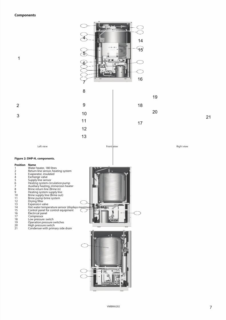
Components
Figure 2: DHP-H, components.
Position Name
1 Water heater, 180 litres2 Return line sensor, heating system3 Evaporator, insulated4 Exchange valve5 Supply line sensor6 Heating system circulation pump7 Auxiliary heating, immersion heater8 Brine return line (Brine in)9 Heating system supply line10 Brine supply line (Brine out)11 Brine pump brine system12 Drying filter13 Expansion valve14 Hot water temperature sensor (displays maximum temperature)15 Control panel for control equipment16 Electrical panel17 Compressor18 Low pressure switch19 Operation pressure switches20 High pressure switch21 Condenser with primary side drain

8/3/2019 Dhp Install Vmbma202 En
http://slidepdf.com/reader/full/dhp-install-vmbma202-en 8/96
8 VMBMA202
2.2 DHP-C
Dimensions and connections
The brine pipes can be connected on either the left or right-handsides of the heat pump.
Figure 3: DHP-C, Dimensions and connections.
Position Name1 Brine return line (Brine in), 28 Cu2 Brine supply line (Brine out), 28 Cu3 Heating system supply line, 22 Cu: 4-10 kW, 28 Cu: 12-16 kW4 Heating system return line, 22 Cu: 4-10 kW, 28 Cu: 12-16 kW5 Expansion pipe, 22 Cu6 Lifting point7 Hot water pipe, 22 Cu or stainless steel8 Cold water pipe, 22 Cu or stainless steel9 Lead-in for incoming power supply, sensors and
communication cable
1 1 0
1 7 9 4
( ± 1 0 )
455
596
5 2 8
300
440
40±10
2
1
5 4 9
3 4 4
6 1 0
327
4 0
80
74
56
8 0
4
7 8
6
5
9
3
8/3/2019 Dhp Install Vmbma202 En
http://slidepdf.com/reader/full/dhp-install-vmbma202-en 9/96
9VMBMA202
Left view Front view Right view
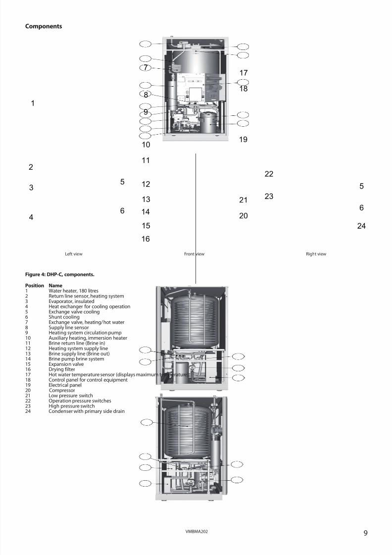
Components
12
11
17
1
4
16
15
14
2
24
6
5
20
21
5
6
19
13
18
7
8
9
10
3
23
22
Figure 4: DHP-C, components.
Position Name
1 Water heater, 180 litres2 Return line sensor, heating system3 Evaporator, insulated4 Heat exchanger for cooling operation5 Exchange valve cooling6 Shunt cooling7 Exchange valve, heating/hot water8 Supply line sensor9 Heating system circulation pump10 Auxiliary heating, immersion heater11 Brine return line (Brine in)12 Heating system supply line13 Brine supply line (Brine out)14 Brine pump brine system15 Expansion valve16 Drying filter17 Hot water temperature sensor (displays maximum temperature)18 Control panel for control equipment19 Electrical panel20 Compressor21 Low pressure switch22 Operation pressure switches23 High pressure switch24 Condenser with primary side drain
8/3/2019 Dhp Install Vmbma202 En
http://slidepdf.com/reader/full/dhp-install-vmbma202-en 10/96
10 VMBMA202
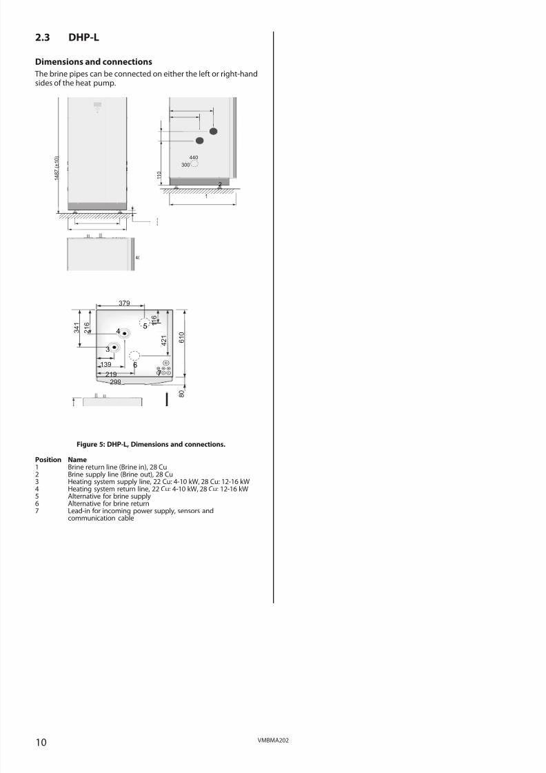
2.3 DHP-L
Dimensions and connections
The brine pipes can be connected on either the left or right-handsides of the heat pump.
Figure 5: DHP-L, Dimensions and connections.
Position Name1 Brine return line (Brine in), 28 Cu2 Brine supply line (Brine out), 28 Cu3 Heating system supply line, 22 Cu: 4-10 kW, 28 Cu: 12-16 kW4 Heating system return line, 22 Cu: 4-10 kW, 28 Cu: 12-16 kW5 Alternative for brine supply6 Alternative for brine return7 Lead-in for incoming power supply, sensors and
communication cable
1 4 8 7
( ± 1 0 )
455
596 690
40±10
1 1 0
5 2 8
300
440
1
2
3 4 1
2 1 6 1
1 6
4 2 1
6 1 0
139
219
379
299
8 0
3
7
4
6
5

8/3/2019 Dhp Install Vmbma202 En
http://slidepdf.com/reader/full/dhp-install-vmbma202-en 11/96
11VMBMA202
Left view Front view Right view
Components
6
5
1
2
4
10
9
8
3
18
14
15
13
12
7
7
11
17
16
Figure 6: DHP-L, components.
Position Name1 Auxiliary heating, immersion heater2 Return line, heating system3 Exchange valve4 Evaporator, insulated5 Heating system circulation pump6 Supply line sensor, heating system7 Brine supply line (Brine out)8 Brine pump brine system9 Drying filter10 Expansion valve11 Control panel for control equipment12 Brine return line (Brine in)13 Electrical panel14 Compressor15 Low pressure switch16 Operation pressure switches17 High pressure switch18 Condenser with primary side drain

8/3/2019 Dhp Install Vmbma202 En
http://slidepdf.com/reader/full/dhp-install-vmbma202-en 12/96
12 VMBMA202
2.4 DHP-A
Dimensions and connections
The brine pipes can be connected on either the left or right-handsides of the heat pump.
Figure 7: DHP-A, Dimensions and connections.
Position Name1 Lead-in for incoming power supply, sensors and
communication cable2 Brine return line (Brine in), 28 Cu3 Brine supply line (Brine out), 28 Cu4 Heating system supply line, 22 Cu: 6-10 kW, 28 Cu: 12 kW5 Heating system return line, 22 Cu: 6-10 kW, 28 Cu: 12 kW6 Expansion pipe, 22 Cu7 Hot water pipe, 22 Cu or stainless steel8 Cold water pipe, 22 Cu or stainless steel9 Lifting point10 Expansion outlet brine circuit, DN25 int.
Figure 8: Outdoor unit, Dimensions and connections.
Position Name1 Brine in (from HP Brine out) 28 Cu2 Brine out (to HP Brine in) 28 Cu
Figure 9: Outdoor unit components and connections
Position Name1 Outdoor unit2 Cover3 Front cover4 Stand5 Cover6 Connection, brine in7 Connection, brine out8 Connection, drain drip tray
Check that the delivery of the outdoor unit contains the following:• Outdoor unit
• Disassembled stand
• Necessary screws, nuts and washers.
• Defroster sensor
1 7 9 4
( ± 1 0 )
455
596
5 2 8
2 5 8
250
300
40±10
2
3
5 4 9
3 4 4
6 1 0
327
4 0
80
74
56
8 0
5
7 8
9
6
10
1
4
1175
6 3 0
4 0 5
1 2 0 0
1
12
2
6
7 8
1
2
3
4
5

8/3/2019 Dhp Install Vmbma202 En
http://slidepdf.com/reader/full/dhp-install-vmbma202-en 13/96
13VMBMA202
Left view Front view Right view
Components
10
14
1
2
3
12
11
13
22
2318
19
16
179
15
5
6
7
8
21
20
4
Figure 10: DHP-A, components.
Position Name
1 Water heater, 180 litres2 Defrosting tank 3 Evaporator, insulated4 Exchange valve, defrosting5 Exchange valve, heating system6 Supply line sensor7 Heating system circulation pump8 Auxiliary heating, immersion heater9 Brine pump brine system10 Brine return line (Brine in)11 Drying filter12 Expansion valve13 Brine supply line (Brine out)14 Hot water temperature sensor (displays maximum temperature)15 Control panel for control equipment16 Electrical panel17 Heating system supply line18 Compressor19 Low pressure switch20 Operation pressure switches21 High pressure switch22 Condenser with primary side drain23 Return line sensor, heating system

8/3/2019 Dhp Install Vmbma202 En
http://slidepdf.com/reader/full/dhp-install-vmbma202-en 14/96
14 VMBMA202
2.5 DHP-AL
Dimensions and connections
The brine pipes can be connected on either the left or right-handsides of the heat pump.
Figure 11: DHP-AL, dimensions and connections.
Position NameHeat pump1 Brine out, during defrosting, 28 Cu2 Return line water heater, 28 Cu3 Brine in4 Heating system supply line, 22 Cu: 6-10 kW, 28 Cu: 12 kW5 Heating system return line, 22 Cu: 6-10 kW, 28 Cu: 12 kW6 Brine out, normal operationWater heater7 Brine in, during defrosting8 Water heater, return line9 Bleed valve, at stainless steel water heater10 Brine out, during defrosting11 Domestic hot water, 22 Cu
12 Cold water13 Water heater supply line to TWS coil14 Brine, expansion line when outdoor unit is positioned at high
level15 Lead-in power and sensor lead16 Lead-in sensor lead17 Lifting point
Figure 12: Outdoor unit, Dimensions and connections.
Position Name1 Brine in (HP Brine out) 28 Cu2 Brine out (HP Brine in) 28 Cu
Figure 13: Outdoor unit components and connections.
Position Name1 Outdoor unit2 Cover3 Front cover4 Stand5 Cover6 Connection, brine in7 Connection, brine out8 Connection, drain drip tray
Check that the delivery of the outdoor unit contains the following:
• Outdoor unit
• Disassembled stand
• Necessary screws, nuts and washers.
• Defroster sensor
1
4
56
10
14
13
9
1112
17
15
16
278
3
1 4 8 7
( ± 1 0 )
455
5 9 6
40±10
455
40±10
1175
6 3 0
4 0 5
1 2 0 0
1
12
2
Heat pump Water heater
6
7 8
1
2
3
4
5
8/3/2019 Dhp Install Vmbma202 En
http://slidepdf.com/reader/full/dhp-install-vmbma202-en 15/96
15VMBMA202
Left view Front view Right view
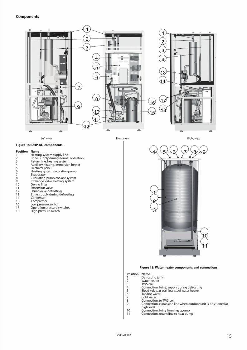
Components
Figure 14: DHP-AL, components.
Position Name1 Heating system supply line2 Brine, supply during normal operation3 Return line, heating system4 Auxiliary heating, immersion heater5 Electrical panel6 Heating system circulation pump7 Evaporator8 Circulation pump coolant system9 Exchange valve, heating system
10 Drying filter11 Expansion valve12 Shunt valve defrosting13 Brine, supply during defrosting14 Condenser15 Compressor16 Low pressure switch17 Operation pressure switches18 High pressure switch
Figure 15: Water heater components and connections.
Position Name1 Defrosting tank 2 Water heater3 TWS coil4 Connection, brine, supply during defrosting5 Bleed valve, at stainless steel water heater6 Tap hot water7 Cold water8 Connection, to TWS coil9 Connection, expansion line when outdoor unit is positioned at
high level10 Connection, brine from heat pump11 Connection, return line to heat pump
6
4
1
3
9
12
15
16
14
13
5
8
10
11
17
18
7
2
4
1
3
2
1
2
3
4 5 6 7
10
11
8 9

8/3/2019 Dhp Install Vmbma202 En
http://slidepdf.com/reader/full/dhp-install-vmbma202-en 16/96
16 VMBMA202
2.6 Package contents
Delivery check
1. Check that there is no transport damage. The heat pump ispackaged in cardboard.
2. Remove the plastic wrapping and check that the delivery con-tains the following components.
Sizes 4kW - 10kW:
Part no. Quantity Name
086U2369 1 Safety valve 9 bar 1/2”
086U2701 1 Outdoor sensor
Kimsafe 200 035
086U0896 1 Safety valve
1.5 bar 1/2”
086U2824 1 Expansion and bleed tank without valve
086U0026 5 Rubber collar hole 22-32mm
086U6033 2 Flex. hose DN20 L=550
086U6006 1 Filling device brine DN25
086U6005 1 Dirt filter with shut-off DN25
Sizes 12kW - 16kW:
Part no. Quantity Name
086U2369 1 Safety valve 9 bar 1/2”
086U2701 1 Outdoor sensor
Kimsafe 200 035
086U0896 1 Safety valve
1.5 bar 1/2”
086U2824 1 Expansion and bleed tank without valve
086U0026 5 Rubber collar hole 22-32mm
086U6034 2 Flex. hose DN25 L=550
086U6007 1 Filling device brine DN32
086U6005 1 Dirt filter with shut-off DN25

8/3/2019 Dhp Install Vmbma202 En
http://slidepdf.com/reader/full/dhp-install-vmbma202-en 17/96
17VMBMA202
2.7 Heat pump control panel The heat pump control panel consists of a display, four control but-tons and an indicator.
Figure 16: Display, control buttons and indicator for the heatpump.
The control computer is controlled using a user-friendly menu sys-tem, displayed in the display.
Use the four control buttons to navigate the menus and increase orreduce the set values:
• An up button with a plus sign
• A down button with a minus sign
• A right button with a right arrow
• A left button with a left arrow
The main menu, INFORMATION, is opened by pressing the left orright buttons. From INFORMATION one of the four sub-menus canbe opened: OPERAT.; HEATCURVE; TEMPERATURE and OPERAT. TIME.
For installation or service, a hidden service menu, SERVICE, is used. This is opened by holding the left button depressed for five sec-onds. From the SERVICE menu one of the following sub-menus canbe opened: WARMWATER; HEATPUMP; ADD.HEAT; MANUAL TESTand INSTALLATION.
For further information about the menus see the service instruc-tions.
The indicator at the bottom of the control panel has two modes:
• Lit steadily, the installation has power and is ready to produceheat or hot water
• Flashing, means an active alarm
2.8 Transporting the heat pump. The heat pump must always be transported and stored upright.Secure the heat pump so that it cannot tip over during transporta-tion.
When transporting indoors to the installation location it may benecessary to place the heat pump on its back. The time that theheat pump is transported on its back should be as short as possible.After the heat pump has been lifted up again it must stand uprightfor at least an hour before commissioning.
2.9 Space requirement To facilitate the installation and subsequent testing and mainte-nance it is recommended that there is sufficient free space aroundthe heat pump in accordance with the following dimensions:
– 300 mm on each side
– 300 mm above
– 600 mm in front
– 10 mm behind
Figure 17: Necessary service space.
Figure 18: Minimum headroom for heat pump installation.
2.10 Recommended location
⚠ To avoid condensation problems for the brine pipes, as short
a brine pipe as possible is recommended. The heat pump should be located on a stable floor, preferablymade of concrete. When locating the heat pump on a wooden floorthis should be reinforced to take the weight. One solution is toplace a thick metal plate, at least 6mm, under the heat pump. Themetal plate should cover several joists spreading the weight of theheat pump over a larger area. If the heat pump is being installedin a newly-built house, this has normally been taken into accountduring construction, and the joists where the heat pump will belocated have been reinforced. Always check that this has been car-ried out when installing into a newly-built house. Avoid positioningthe heat pump in a corner as the surrounding walls may amplify itsnoise. It is also important to adjust the heat pump using the adjust-able feet so that it is horizontal to the base.
The symbols in the display areonly examples. Certain sym-bols cannot be displayed atthe same time.
ROOM 20°C(20°C)
NO DEMAND HEATOPERAT. AUTO
1 9 0 5
1 6 2 0
DHP-H
DHP-CDHP-A
DHP-LDHP-AL

8/3/2019 Dhp Install Vmbma202 En
http://slidepdf.com/reader/full/dhp-install-vmbma202-en 18/96
18 VMBMA202
2.11 Space requirement, outdoor unit,
DHP-A, -AL
• To ensure the function of the outdoor unit, there must be at least300 mm of space behind and 1500 mm at the front.
• For maintenance work there must be approximately 300 mm of space at the sides of the outdoor unit.
Figure 19: Necessary service space for outdoor unit.
2.12 Recommended location of outdoor unit,DHP-A, -AL
When positioning the outdoor unit, note the following:
⚠ The outdoor unit does not have to be positioned in any spe-cific direction.
⚠ Noise is produced from the outdoor unit when the fan is inoperation, remember this when positioning to reduce distur-bance in your own home as well as to any neighbours.
⚠ When the outdoor unit is defrosting, water will drip straightdown under the unit. The area around the outdoor unit musttherefore be properly drained in order to catch the water(approximately 2 litres per defrost).
⚠ Remember that the outdoor unit must have a certain amountof room in order to function and for servicing, see “Heatpump information” chapter.
⚠ Remember that the water that drips from the outdoor unitduring defrost must be able to drain into the ground. Theoutdoor unit must therefore not be positioned on asphalt orslabs where water cannot drain easily.
⚠ The outdoor unit’s adjustable stand must be positioned ona secure base such as wooden sleepers, paving slabs or castfootings.
3 Drilling holes for brine pipes
⚠ NOTE! Ensure that the holes for the insert pipes are posi-tioned so that there is room for the other installations.
⚠ NOTE! The brine pipes shall have separate lead-ins.
⚠ If the wall lead-ins are below the highest ground water levelwatertight lead-ins must be used.
The brine pipes must be insulated from the heat pump, throughthe walls and outside the house all the way to the collector so as to
avoid condensation and prevent heat loss.If the brine pipes are to be routed above ground, drill holes in thewalls for them.
If the brine pipes are to be routed below ground see the instruc-tions below.
Figure 20: Drilling holes for brine pipes.
Position Name1 Insert pipe2 Brine pipe3 Mortar4 Sealant
1. Drill holes in the wall for the insert pipes (1) for the brine pipes.Follow the dimension and connection diagrams in the section“Heat pump information”. If there is any risk of groundwaterinfiltration at brine pipe lead-ins, watertight grommets must beused.
2. Position the insert pipes (1) in the holes sloping downwards. The inclination must be at least 1cm every 30cm. Cut them atan angle (as illustrated) so that rain water cannot get into thepipes.
3. Insert the brine pipes (2) into the insert pipes in the installationroom.
4. Fill in the holes in the wall with mortar (3).
5. Ensure that the brine pipes (2) are centred in the insert pipes (1)so that the insulation is distributed equally on all sides.
6. Seal the insert pipes (1) with a suitable sealant (foam) (4).

8/3/2019 Dhp Install Vmbma202 En
http://slidepdf.com/reader/full/dhp-install-vmbma202-en 19/96
19VMBMA202
4 Separating the heat pumpDoes not apply to DHP-A, -AL.
If there is a shortage of space when transporting the heat pump toinstallation location it may be necessary to separate the heat pumpunit and the water heater.
The following instruction describes how the heat pump is sepa-rated to transport the separate parts more easily.
⚠ NOTE! Do not lift heavy equipment alone, always use twopeople for heavy lifting.
1. Remove the packaging.
2. Press against the front cover; and turn the catch 90° degreesanti-clockwise to release the front cover.
3. Tilt the front cover outwards.
4. Lift the front cover upwards to remove it from the heat pump.
Figure 21: The front cover.
5. Carefully pull the switch free from the control panel.
6. Unscrew the front cross stay, the top cover, side covers and rearcover.
Figure 22: Covers.
7. Disconnect the electrical connectors at the exchange valve, cir-culation pump and electrical auxiliary heater.
8. Disconnect the cables for the following sensors at the electrical
panel:- Supply line (301, 302)
- Hot water (311, 312)
-Top sensor (325, 326)
9. Unscrew the electrical panel’s screws.
10. Turn the electrical panel through 180° and place it in front of the heat pump unit.
Figure 23: Electrical panel.
11. Disconnect the T-pipe connector from the return line under theheater, see figure below.
12. Disconnect the flexible hose at the electrical auxiliary heater,see figure below.
Figure 24: Connections.
13. Unscrew the four screws in the corners that hold the waterheater’s bottom plate.
⚠ NOTE! Always use two people for heavy lifting.
14. Lift off the unit with the water heater, pipe and electrical auxil-iary heater.
Figure 25: Separating.
15. Put the unit down carefully.
1
2
3
8/3/2019 Dhp Install Vmbma202 En
http://slidepdf.com/reader/full/dhp-install-vmbma202-en 20/96
20 VMBMA202
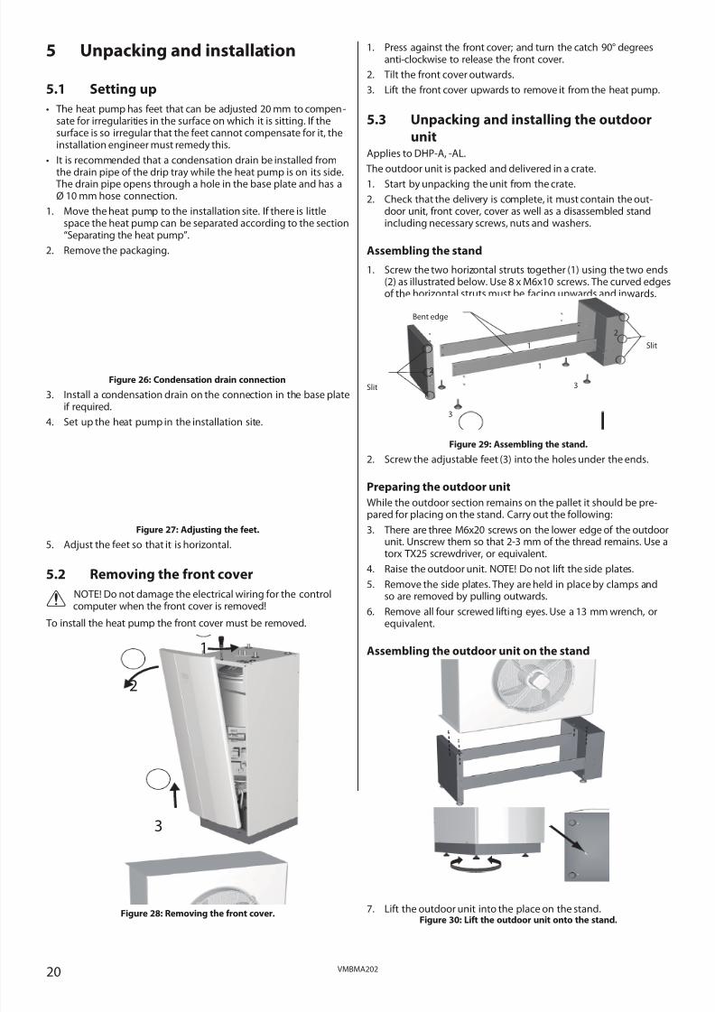
5 Unpacking and installation
5.1 Setting up
• The heat pump has feet that can be adjusted 20 mm to compen-sate for irregularities in the surface on which it is sitting. If thesurface is so irregular that the feet cannot compensate for it, theinstallation engineer must remedy this.
• It is recommended that a condensation drain be installed from
the drain pipe of the drip tray while the heat pump is on its side. The drain pipe opens through a hole in the base plate and has aØ 10 mm hose connection.
1. Move the heat pump to the installation site. If there is littlespace the heat pump can be separated according to the section“Separating the heat pump”.
2. Remove the packaging.
Figure 26: Condensation drain connection
3. Install a condensation drain on the connection in the base plateif required.
4. Set up the heat pump in the installation site.
Figure 27: Adjusting the feet.5. Adjust the feet so that it is horizontal.
5.2 Removing the front cover
⚠ NOTE! Do not damage the electrical wiring for the controlcomputer when the front cover is removed!
To install the heat pump the front cover must be removed.
Figure 28: Removing the front cover.
1. Press against the front cover; and turn the catch 90° degreesanti-clockwise to release the front cover.
2. Tilt the front cover outwards.
3. Lift the front cover upwards to remove it from the heat pump.
5.3 Unpacking and installing the outdoor
unitApplies to DHP-A, -AL.
The outdoor unit is packed and delivered in a crate.
1. Start by unpacking the unit from the crate.
2. Check that the delivery is complete, it must contain the out-door unit, front cover, cover as well as a disassembled standincluding necessary screws, nuts and washers.
Assembling the stand
1. Screw the two horizontal struts together (1) using the two ends(2) as illustrated below. Use 8 x M6x10 screws. The curved edgesof the horizontal struts must be facing upwards and inwards.
Figure 29: Assembling the stand.
2. Screw the adjustable feet (3) into the holes under the ends.
Preparing the outdoor unit
While the outdoor section remains on the pallet it should be pre-pared for placing on the stand. Carry out the following:
3. There are three M6x20 screws on the lower edge of the outdoorunit. Unscrew them so that 2-3 mm of the thread remains. Use atorx TX25 screwdriver, or equivalent.
4. Raise the outdoor unit. NOTE! Do not lift the side plates.
5. Remove the side plates. They are held in place by clamps andso are removed by pulling outwards.
6. Remove all four screwed lifting eyes. Use a 13 mm wrench, orequivalent.
Assembling the outdoor unit on the stand
7. Lift the outdoor unit into the place on the stand.Figure 30: Lift the outdoor unit onto the stand.
1
2
3
1
1
2
3
3
2
Slit
Slit
Bent edge
8/3/2019 Dhp Install Vmbma202 En
http://slidepdf.com/reader/full/dhp-install-vmbma202-en 21/96
21VMBMA202
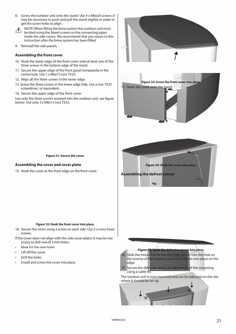
8. Screw the outdoor unit onto the stand. Use 4 x M6x20 screws. Itmay be necessary to push and pull the stand slightly in order toget the screw holes to align.
⚠ NOTE! When filling the brine system the outdoor unit mustbe bled using the bleed screws on the connecting pipesinside the side covers. We recommend that you return to thisinstruction after the brine system has been filled.
9. Reinstall the side panels.
Assembling the front cover
10. Hook the lower edge of the front cover onto at least one of thethree screws in the bottom edge of the stand.
11. Secure the upper edge of the front panel temporarily in thecentre hole. Use 1 x M6x15 torx TX25.
12. Align all the three screws in the lower edge.
13. Screw the three screws in the lower edge fully. Use a torx TX25screwdriver, or equivalent.
14. Secure the upper edge of the front cover.
Use only the three screws screwed into the outdoor unit, see figurebelow. Use only 3 x M6x15 torx TX25.
Figure 31: Secure the cover.
Assembling the cover and cover plate
15. Hook the cover at the front edge on the front cover.
Figure 32: Hook the front cover into place.
16. Secure the cover using a screw on each side. Use 2 x cross head
screws.If the cover does not align with the side cover plates it may be nec-
essary to drill new Ø 3 mm holes:
• Mark for the new holes
• Lift off the cover
• Drill the holes
• Install and screw the cover into place
Figure 33: Screw the front cover into place.
17. Hook the cover onto the stand.
Figure 34: Hook the cover into place.
Assembling the defrost sensor
Figure 35: Hook the defroster sensor into place.
18. Slide the mounting for the defroster sensor into the hole onthe reverse of the outdoor unit until it hooks into place on theedge.
19. Secure the defroster sensor at the bottom of the mountingusing a cable tie.
The outdoor unit is now mounted and can be adjusted on the sitewhere it should be set up.

8/3/2019 Dhp Install Vmbma202 En
http://slidepdf.com/reader/full/dhp-install-vmbma202-en 22/96
22 VMBMA202
6 Piping installation
⚠ NOTE! To prevent leaks ensure that there are no stresses inthe connecting pipes!
⚠ NOTE! It is important that the heating system is completelybled after installation.
⚠ NOTE! Bleed valves must be installed where necessary.
• Ensure that the piping installation follows the dimension andconnection diagrams in section “Heat pump information”.
• Piping installation must be carried out in accordance with appli-cable local rules and regulations. The hot water tank must beequipped with an approved safety valve (supplied).
Selecting the heating system
The heat pump is set to VL system on delivery, that is with an inte-grated electrical auxiliary heater and an exchange valve after theauxiliary heater.
What determines which of the three systems VL, D or VLD shouldbe used is, among other things, how any auxiliary heater is used forhot water production, and which model of heat pump is used.
6.1 VL systemIn a VL system the heat pump can produce both heating and hotwater with the compressor and the integrated auxiliary heater.
Production of heating and hot water cannot occur at the same timebecause the exchange valve for heating/hot water is positionedafter the auxiliary heater.
The integrated auxiliary heater carries out peak heating charging(legionella function) in those operating modes that permit auxiliaryheat.
DHP-H, -C, -A, connection diagram VL system
Figure 36: General connection diagram DHP-H, -C, -A.
Position Name1 Supply line2 Return line3 Safety valve cold water (9 bar)4 Safety valve expansion heating system (not included)5 Expansion heating system (not included)6 Strainer7 Flexible hoses8 Vacuum valve9 Non-return valve10 Shut-off valve11 Non-return valve12 Shut-off valve13 Hot water
14 Cold water15 Heat pump

8/3/2019 Dhp Install Vmbma202 En
http://slidepdf.com/reader/full/dhp-install-vmbma202-en 23/96
23VMBMA202
DHP-L, connection diagram VL system
Figure 37: General connection diagram DHP-L.
Position Name1 Supply line2 Return line3 Safety valve cold water (9 bar)4 Safety valve expansion heating system (not included)5 Expansion heating system (not included)6 Strainer7 Flexible hoses8 Vacuum valve9 Non-return valve10 Shut-off valve11 Cold water
12 Hot water13 Heat pump14 Water heater
DHP-AL, connection diagram VL system
Figure 38: General connection diagram DHP-AL.
Position Name1 Heat pump2 Supply line3 Return line4 Safety valve (not included)5 Expansion tank (not included)6 Strainer7 Flexible hoses8 Bleed valve9 Mixer valve10 Exchange valve11 Safety valve (9 bar)12 Vacuum valve13 Non-return valve
14 Shut-off valve15 Cold water16 Hot water17 Water heater18 Bleed valve at stainless steel water heater
114
5
7
7
12 13 14
16
15
1 17
18
6
2
10
9
3
8

8/3/2019 Dhp Install Vmbma202 En
http://slidepdf.com/reader/full/dhp-install-vmbma202-en 24/96
24 VMBMA202
6.2 D system: DHP-LWith a DHP-L in a D system, the heat pump can produce both heat-ing and hot water with the compressor and an external auxiliaryheater (oil boiler, electric boiler, district heating or similar) that islocated after the exchange valve replaces the integrated auxiliaryheater to produce heat.
The cables for the integrated auxiliary heater must be disconnect-ed, which means that the heat pump cannot carry out peak heatcharging (legionella function). Peak heat charging must take placewith an electric heating element that is integrated in the water
heater or with an electric heating element on the supply line to thewater heater.
The heat pump control computer also controls an additional shunt.
DHP-L, connection diagram D system
Figure 39: General connection diagram DHP-L, D system.
Position Name1 Supply line2 Return line3 Safety valve cold water (9 bar)4 Safety valve expansion heating system (not included)5 Expansion heating system (not included)6 Strainer7 Flexible hoses8 Vacuum valve9 Non-return valve10 Shut-off valve11 Cold water12 Hot water13 Heat pump14 Water heater15 External auxiliary heater16 Circulation pump17 Non-return valve18 Moved supply line sensor19 Additional shunt
6.3 VLD system: DHP-A, -AL
A VLD system is largely similar to a VL system, but with an externalauxiliary heater (often a boiler that is fired with solid fuel) in combi-nation with a DHP-A or DHP-AL.
DHP-A’s integrated exchange valve is replaced by an exchangevalve that is located after the external auxiliary heater so that boththe heat pump and the auxiliary heater can produce heat and hotwater. The integrated exchange valve is disengaged with the flowdirection locked towards the heating system.
Production of heating and hot water cannot occur at the same timebecause the exchange valve for heating/hot water is positionedafter the auxiliary heater. The integrated auxiliary heater carriesout peak heating charging (legionella function) in those operatingmodes that permit auxiliary heat.
The heat pump’s control computer controls the external additionalheater via an output (283) on the defrosting card (factory installedin DHP-A or DHP-AL). The heat pump control computer also con-trols an additional shunt.
DHP-A, connection diagram VLD system
Figure 40: General connection diagram DHP-A, VLD system.
Position Name1 Supply line2 Return line3 Safety valve cold water (9 bar)4 Safety valve expansion heating system (not included)5 Expansion heating system (not included)6 Strainer7 Flexible hoses8 Vacuum valve9 Non-return valve10 Shut-off valve11 Non-return valve12 Shut-off valve13 Hot water14 Cold water15 Heat pump16 External auxiliary heater17 Circulation pump18 Non-return valve19 Moved supply line sensor20 Additional shunt21 External exchange valve

8/3/2019 Dhp Install Vmbma202 En
http://slidepdf.com/reader/full/dhp-install-vmbma202-en 25/96
25VMBMA202
DHP-AL, connection diagram VLD
Figure 41: General connection diagram DHP-AL, system VLD.
Position Name1 Heat pump2 Supply line3 Return line4 Safety valve (not included)5 Expansion tank (not included)6 Strainer7 Flexible hoses8 -9 Mixer valve10 Exchange valve11 Safety valve (9 bar)12 Vacuum valve
13 Non-return valve14 Shut-off valve15 Cold water16 Hot water17 Water heater18 Bleed valve at stainless steel water heater19 External auxiliary heater20 Circulation pump21 Non-return valve22 Moved supply line sensor23 Additional shunt
6.4 Safety valves
⚠ Radiator systems with a closed expansion tank must also beequipped with an approved pressure gauge and safety valve,minimum DN 20, for a maximum 1.5 bar opening pressure, or
according to country specific requirements.
⚠ Cold and hot water pipes as well as overflow pipes fromsafety valves must be made of heat resistant and corrosion-resistant material, e.g. copper. The safety valve overflow pipesmust have an open connection to the drain and visibly flowinto this in a frost-free environment.
⚠ The connecting pipe between the expansion tank and thesafety valve must slope continuously upwards. A continuousupwards slope means that the pipe must not slope down-wards from the horizontal at any point.
6.5 Connecting cold and hot water pipes
1. Connect the cold water and hot water pipes with all the neces-
sary components according to the connection diagram for therelevant system.
6.6 Connecting the heating system supply
and return linesAll pipes should be routed in such a way that vibrations cannot betransmitted from the heat pump through the piping and out intothe building. This also applies to the expansion pipe. To avoid thetransmission of vibrations, we recommend that flexible hoses areused for the supply line and return line on both the heating systemand brine system sides. Flexible hoses are available to purchasefrom Danfoss AS. Figures 12-15 show how appropriate and inappro-priate installations look using this type of hose.
To avoid noise caused by pipe mounting, rubber-coated clamps shouldbe used to prevent the transmission of vibrations. However, installationshould not be too rigid and the clamps must not be too tight.
Figure 42: Do not twist the flexible hoses as they are installed.At threaded connections, use a counterhold spanner.
Figure 43: Cut the hose to the correct length to avoid excessbowing-out or stretching at bends.
Figure 44: Cut the hose to the correct length to avoid excessbowing-out or stretching and offset the ends so that the hose is
not installed completely straight.
Figure 45: Use fixed pipe bends to avoid excess stress on bendsnext to connections.
1. Connect the supply line with a flexible hose connection andwith all the necessary components.
2. Connect the return line with a flexible hose connection andwith all the necessary components including a filter.
11
4
5
7
7
12 13
23 10
14
16
15
1 17
18
22
19
20
21
6
2
9
3

8/3/2019 Dhp Install Vmbma202 En
http://slidepdf.com/reader/full/dhp-install-vmbma202-en 26/96
26 VMBMA202
3. Insulate the supply and return lines.
4. Connect the expansion tank to the expansion outlet (22mm Cu)
on the top of the heat pump.
6.7 Filling the water heater and heating sys-
tem
1. Fill the water heater with cold water by opening the filler valve(10) which is located on the valve pipe.
2. Bleed by opening one of the hot water taps.
3. Then fill the water heater coil and the heating system withwater through the filling valve (12) to a pressure of approx. 1bar.
6.8 Bleeding the heating system
1. Open all radiator valves fully.
2. Bleed all radiators.
3. Refill the heating system to a pressure of approximately 1 bar.
4. Repeat the procedure until all air has been removed.
5. Leave the radiator valves fully open.
7 Electrical Installation
⚠ Electrical current! The terminal blocks are live and can behighly dangerous due to the risk of electric shock. The powersupply must be isolated before electrical installation is start-ed. The heat pump is connected internally at the factory, forthis reason electrical installation consists mainly of the con-nection of the power supply.
• Electrical installation may only be carried out by an authorizedelectrician and must follow applicable local and national regula-
tions.• The electrical installation must be carried out using permanently
routed cables. It must be possible to isolate the power supplyusing an all-pole circuit breaker with a minimum contact gap of 3mm. (The maximum load for externally connected units is 2A).
• Electrical connection can also cause noise so this installationmust be carried out appropriately. The figure below shows anappropriate installation. There is approximately 300mm freecable between the heat pump and building, however, thisrequires the cable to be securely installed onto the top panel sothat the cable cannot be fed into the heat pump. It is inappropri-ate to bolt trunking between the heat pump and the wall. This isbecause vibrations can then be transmitted from the heat pumpthrough the trunking to the walls of the house.
• When the cable is connected to the terminal block a screwdriveris used to open the terminal block, see figure below.
Figure 46: Connecting cable to terminal block.
Figure 47: The location of the components on the electrical panel.
Position Name1 Terminal block (applies to the expansion card)2 Terminal block (applies to DHP-A, -AL)3 Defrost card (applies to DHP-A, -AL)4 Terminal block 5 Space for Danfoss Online6 Warning decal7 Space for expansion card8 Contactor for compressor9 Automatic fuses10 Resetting overheating protection
11 Control computer12 Soft starter card (Only available for 400 V)
1
2 3 5 OK!
4
1 2 3
5
7
6
4
8
9
121110

8/3/2019 Dhp Install Vmbma202 En
http://slidepdf.com/reader/full/dhp-install-vmbma202-en 27/96
27VMBMA202
Figure 48: Recommended distance between trunking on thewall and trunking on the heat pump is 300mm.
7.1 Connect power supply, 400V 3N
⚠ NOTE! The power cable may only be connected to the termi-nal block intended for this purpose. No other terminal blocksmay be used!
Figure 49: Incoming cable to heat pump with circuit breaker.
⚠ NOTE! Supplied with the jumpers shown in the figure.
1. Route the power cable through the opening in the top panel of the heat pump to the terminal blocks.
2. Connect the power cable to the terminal block.
7.2 Connect power supply, 230V 1N SP
⚠ NOTE! The power cable may only be connected to the termi-nal block intended for this purpose. No other terminal blocksmay be used!
Figure 50: Incoming cable to heat pump.
1. Route the power cable through the opening in the top panel of the heat pump to the terminal blocks.
2. Connect the power cable to the terminal block.
7.3 Position and connect outdoor sensors⚠ NOTE! The outdoor sensor is connected with extra low pro-tection voltage. Follow the specific installation instructionsfor the outdoor sensor!
Figure 51: Positioning the outdoor sensor.
• Position the outdoor sensor on the north or north west side of the house.
• To measure the outdoor temperature as accurately as possible,the sensor must be positioned 2/3 of the way up the facade onhouses up to three storeys high. For higher buildings, the sensorshould be positioned between the second and third storeys. Itslocation must not be completely protected from the wind butnot in a direct draft. The outdoor sensor should not be placed onreflective panel walls.
• The sensor must be positioned at least 1 m from openings in thewalls that emit hot air.
• If the sensor cable is connected through a pipe, the pipe must besealed so that the sensor is not affected by outgoing air.
The outdoor sensor is connected by a two core cable. For a crosssection of 0.75 mm2 a maximum cable length of 50 m applies. For
greater lengths a cross section of 1.5 mm2
is used, up to a maxi-mum of 120 m.
Then connect the sensor to the heat pump control system inaccordance with the instructions below.
Figure 52: Connecting the outdoor sensor.
1. Route the outdoor sensor connection cable through the cablebushing in the top panel to the terminal block.
2. Connect the sensor to the terminal blocks according to the con-nection diagram.
7.4 Changing the language in the controlcomputer
If necessary, change the language in the control computer menus.
1. Ensure that the main circuit breaker is on.
2. Open the SERVICE menu by pressing for five seconds.
3. Change language in the control computer menu SERVICE ->INSTALLATION -> ENGLISH, select language and .
RUM 20CINGET BEHOV VÄRMEDRIFT AUTO
RUM 20CINGET BEHOV VÄRMEDRIFT AUTO
1L1
N2
PE1
2L1,2L1
2L1,2L2
N3
PE4
Incoming 230V heat pump
Incoming 230V external auxiliary heater
H
2 / 3 x H
Recommended location
Unsuitable location

8/3/2019 Dhp Install Vmbma202 En
http://slidepdf.com/reader/full/dhp-install-vmbma202-en 28/96
28 VMBMA202
7.5 Resetting to system D or VLD
For a description of the different system solutions, see sectionPiping installation.
The heat pump has VL as factory setting.
For D system, DHP-L:
If D system is selected the cables for the internal auxiliary heatermust be disconnected according to the figure below.
Figure 53: The cables are disconnected from the auxiliaryheater.
Connect the external auxiliary heater according to the connectiondiagram below.
Figure 54: Connecting external auxiliary heater.
For VLD system, DHP-A, -AL:
If the VLD system is selected DHP-A’s integrated exchange valvemust be limited in open mode to the heating system.
To limit the direction of flow for the exchange valve for the heatingsystem:
1. Ensure that the main circuit breaker is on.
2. Open the SERVICE menu by pressing for five seconds.
3. Open the control computer menu SERVICE -> MANUAL TEST.
4. Set the value for MANUAL TEST to 1.
5. Set the value for VXV HOT WATER to 0.
6. Wait for 15 seconds, disconnect the quick connector at theexchange valve.
7. Set the value for MANUAL TEST back to 0.
8. Connect the external exchange valve cables to the correspond-ing cables in the disconnected quick connector.
In the control computer:
To change to system D or VLD:
1. Ensure that the main circuit breaker is on.
2. Open the SERVICE menu by pressing for five seconds.
3. Change system in the control computer menu SERVICE ->INSTALLATION -> SYSTEM -> HEATING SYSTEM, select systemwith and .
7.6 Changing the number of auxiliary heat-
ing power stages
⚠ NOTE! Setting the maximum permitted number of powerstages for the auxiliary heating must be carried out.
1. Ensure that the main circuit breaker is on.
2. Open the SERVICE menu by pressing for five seconds.
3. Change the number of auxiliary heating power stages in thecontrol computer menu SERVICE -> ADD.HEAT -> MAXSTEP,select the number of stages and .
7.7 Connect outdoor unit, DHP-A, -AL
⚠ NOTE! The power cable may only be connected to the termi-nal block intended for this purpose. No other terminal blocksmay be used!
For correct connection between the heat pump and the outdoorunit, 6 connections must be made, see also separate sheet withelectrical connections.
Figure 55: Connecting the outdoor unit.
1. Route the power cable through the opening in the top panel of the heat pump to the terminal blocks.
2. Connect the power cable to the terminal block.
7.8 Connect defrost sensor, DHP-A, -AL
Figure 56: Connecting the defroster sensor.
The defroster sensor is installed on the reverse of the outdoor unit.
1. Route the defroster sensor connection cable through the cablebushing in the top panel to the terminal block.
2. Connect the sensor to the terminal blocks according to the con-nection diagram.
Ground
0V
Peak heating
Oil/electrical
additional heat
Phase high speedPhase low speed
Motor protection fan
8/3/2019 Dhp Install Vmbma202 En
http://slidepdf.com/reader/full/dhp-install-vmbma202-en 29/96
29VMBMA202
8 Brine installation
8.1 Heat sources
Rock heat
To use rock as the heat source one or more boreholes is/are drilled andthe brine hose is lowered into it/them. The hole is filled with water anda fitting with a weight is fastened to the hose before it is lowered.
Figure 57: Borehole in rock as heat source.
Lake heat
When lake water is used as the heat source one or more brine coilsis/are submerged in the water . The coils must be anchored to thebottom with weights or a net to prevent them floating.
Figure 58: Lake water as heat source.
Ground water heating
Ground water can be used as a heat source on the condition thatthere is a sufficiently large flow of ground water in the borehole. Asubmersible pump is lowered in one hole and pumps up ground-water, which flows through a separate heat exchanger, and is thenreturned through another borehole. The heat pump has a shortbrine circuit that works directly against the separate groundwaterexchanger.
Figure 59: Ground water as heat source.
When ground water is used as a heat source the heat pump instal-lation must be equipped with a flow guard (available as an acces-sory from the Danfoss range) that stops the heat pump if the flowis too low, which can create a risk of freezing in the ground waterexchanger.
Ground heat
The stored heat energy in the ground can be used as a heat source.In this case a brine loop (or loops) is/are laid under the surface layerof ground
Figure 60: Ground as heat source.
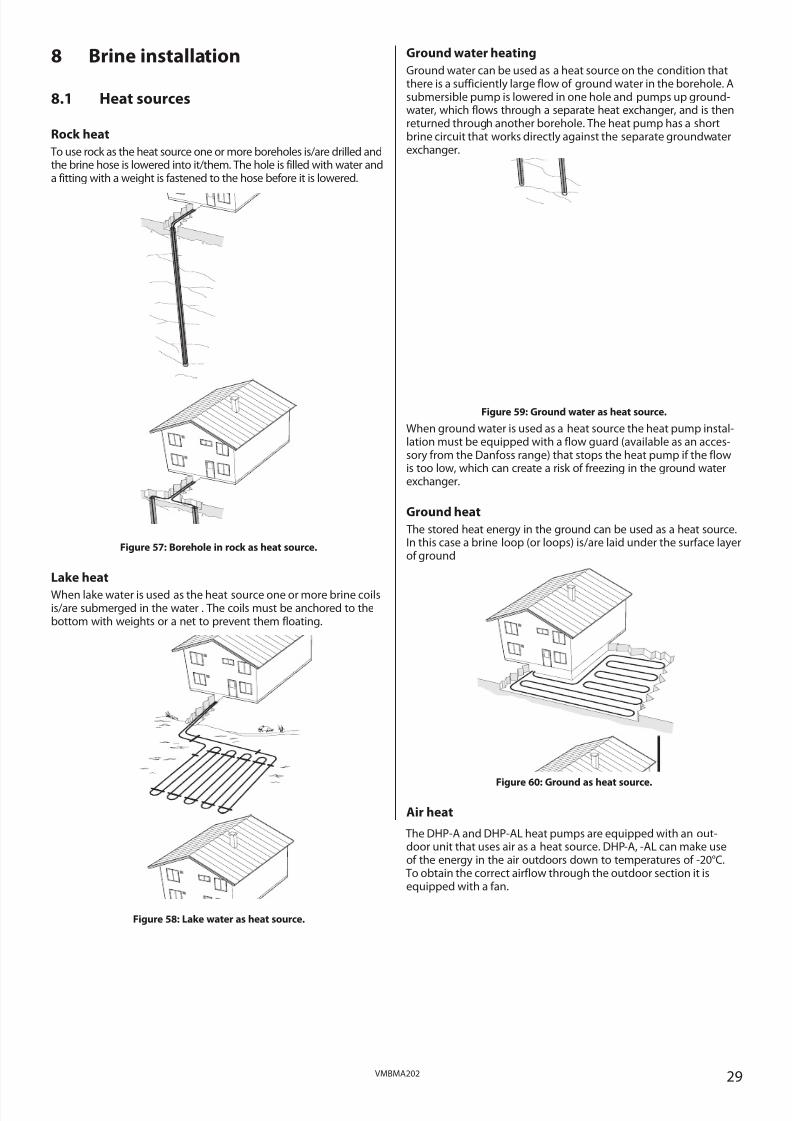
Air heat
The DHP-A and DHP-AL heat pumps are equipped with an out-door unit that uses air as a heat source. DHP-A, -AL can make useof the energy in the air outdoors down to temperatures of -20°C.
To obtain the correct airflow through the outdoor section it isequipped with a fan.

8/3/2019 Dhp Install Vmbma202 En
http://slidepdf.com/reader/full/dhp-install-vmbma202-en 30/96
30 VMBMA202
Figure 61: Connecting outdoor unit to use air as heat source.
8.2 Information collector pipe
⚠ Local rules and regulations related to type of collector mustbe followed.
Borehole collector: Fully welded plastic pipe collector (PEM PN 6.3)according to the applicable local and national regulations with fac-tory manufactured return bend.
Ground collector: Fully welded plastic pipe collector (PEM PN 10)according to the applicable local and national regulations.
In countries where frost damage occurs, the collector pipe beside
an outer wall (minimum 2 meters) must be insulated in such a waythat frost damage is prevented. This applies regardless of ground,rock or lake heat.
Minimum shaft depth between the energy well and the building is0.5 m. If burial to that depth is not possible the pipes must be pro-tected against any external mechanical damage.
Figure 62: Shaft depth for, and insulation of, collector hoses.
8.3 Connection to outdoor unitConnection for the brine circuit from the heat pump to the out-door unit can be carried out using pipes or hoses. Depending onwhat connection is selected and what diameter the connectionhas, there is a maximum length that the connection may be. Themaximum lengths in the table below are based on ethylene glycol(which is mixed to anti-freeze protection down to -32°C) at 0°C.
DHP-A,-AL
Pytg Calculated maximum coil length between theHP and outdoor unit, in metres
Size kPa Cu22Øin = 20.0
Cu28Øin = 25.6
PEMDN 25
Øin = 21.0
PEMDN 32
Øin = 28.0
6 30 34
(2 x 17)
133
(2 x 66.5)
48
(2 x 24)
173
(2 x 86.5)
8 63 21
(2 x 10.5)
98
(2 x 49)
30
(2 x 15)
150
(2 x 75)
10 50 11 *
(2 x 5.5)
47
(2 x 23.5)
13 *
(2 x 6.5)
78
(2 x 39)
12 43 5 *
(2 x 2.5)
26
(2 x 13)
8 *
(2 x 4)
44
(2 x 22)
*) Not recommended because of high liquid speeds with risk of corro-sion/noise problems.
8.4 Connection of several brine coilsWhen several brine coils are used for a heat pump installation, inde-pendent of what heat source is used, the length of the coils mustnot exceed the values in the following table. The coil lengths arebased on ethanol 30% at 0°C.
DHP-H,-C, -L
Pytg Calculated maximum coil length per coil, inmetres
PEM DN 32, Øin = 28,0
Size kPa 1 coil 2 coils 3 coils 4 coils6 31 182 2 x 443 3 x 620 4 x 775
8 33 94 2 x 220 3 x 471 4 x 660
10 67 129 2 x 419 3 x 670 4 x 1117
12 64 91 2 x 376 3 x 640 4 x 914
16 56 37 2 x 165 3 x 329 4 x 400
DHP-H,-C, -L
Pytg Calculated maximum coil length per coil, inmetres
PEM DN 40, Øin = 35,2
Size kPa 1 coil 2 coils 3 coils 4 coils
6 31 517 2 x 775 3 x 1033 4 x 1033
8 33 367 2 x 660 3 x 943 4 x 825
10 67 394 2 x 1340 3 x 1675 4 x 1675
12 64 291* 2 x 1067 3 x 1280 4 x 1600
16 56 119 2 x 560 3 x 933 4 x 1120
*) When dimensioning size 12, a borehole depth that exceeds this rec-ommendation for coil length is often required. In such cases two coilsshould be used.
The different brine coils are distributed form a common collec-tion well. All return lines are led back to the well and are equippedwith choke valves because the flow of each individual coil must beadjusted.
Figure 63: The collection well for distributing to several brine
coils.
Choke valves with flow indicators (available as accessories from theDanfoss range) are used to adjust the brine flow so that it is thesame in all coils.
If choke valves with flow indicators are not available adjust thevalves until the temperature of all the coil return hoses is the same.
>0,5m
>2,0m
Collection well
Choke valves
Brine coil 1
Brine coil 2
8/3/2019 Dhp Install Vmbma202 En
http://slidepdf.com/reader/full/dhp-install-vmbma202-en 31/96
31VMBMA202
8.5 Connection diagram
DHP-C:
Figure 64: General connection diagram brine pipes, DHP-C.
Position Name1 Return line, brine2 Supply line, brine3 Shut-off valve (part of the filler cock)4 Shut-off valve (part of the filler cock)
5 Shut-off valve (part of the filler cock)6 Strainer (part of the filler cock)7 Shut-off valve (part of the filler cock)8 Safety valve (1.5 bar)9 Bleed and expansion tank 10 Shut-off valve
DHP-H, DHP-L:
Figure 65: General connection diagram, brine pipesDHP-H, DHP-L.
Position Name1 Return line, brine2 Supply line, brine
3 Shut-off valve (part of the filler cock)4 Shut-off valve (part of the filler cock)5 Shut-off valve (part of the filler cock)6 Strainer (part of the filler cock)7 Shut-off valve (part of the filler cock)8 Safety valve (1.5 bar)9 Bleed and expansion tank 10 Shut-off valve
DHP-A:
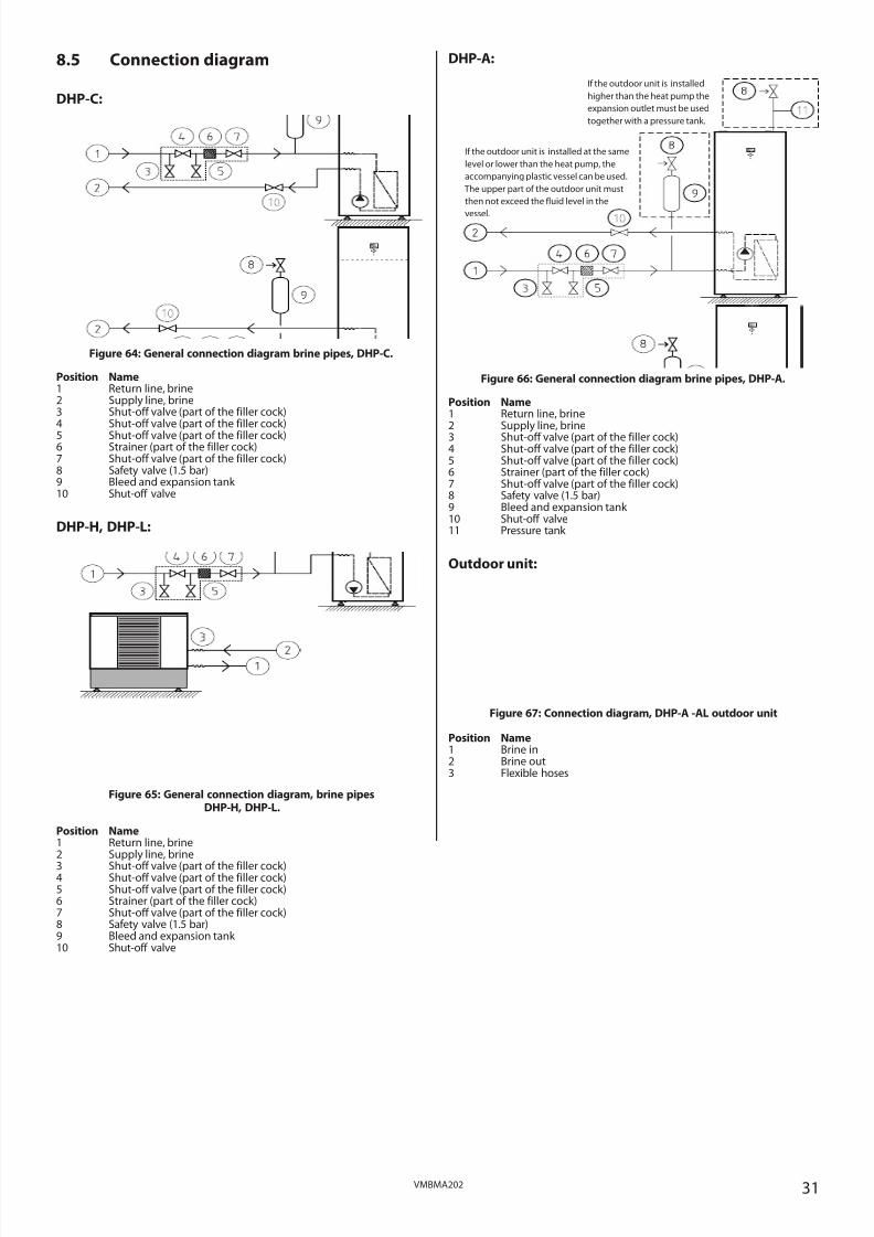
Figure 66: General connection diagram brine pipes, DHP-A.
Position Name1 Return line, brine2 Supply line, brine3 Shut-off valve (part of the filler cock)4 Shut-off valve (part of the filler cock)5 Shut-off valve (part of the filler cock)6 Strainer (part of the filler cock)7 Shut-off valve (part of the filler cock)8 Safety valve (1.5 bar)9 Bleed and expansion tank 10 Shut-off valve11 Pressure tank
Outdoor unit:
Figure 67: Connection diagram, DHP-A -AL outdoor unit
Position Name1 Brine in2 Brine out3 Flexible hoses
If the outdoor unit is installed
higher than the heat pump the
expansion outlet must be used
together with a pressure tank.
If the outdoor unit is installed at the same
level or lower than the heat pump, the
accompanying plastic vessel can be used.
The upper part of the outdoor unit must
then not exceed the fluid level in the
vessel.

8/3/2019 Dhp Install Vmbma202 En
http://slidepdf.com/reader/full/dhp-install-vmbma202-en 32/96
32 VMBMA202
DHP-AL:
Figure 68: Connection diagram for brine pipes.
Position Name1 Return line, brine2 Supply line, brine3 Shut-off valve (part of the filler cock)4 Shut-off valve (part of the filler cock)5 Shut-off valve (part of the filler cock)6 Strainer (part of the filler cock)7 Shut-off valve (part of the filler cock)8 Safety valve (1.5 bar)9 Bleed and expansion tank 10 Shut-off valve11 Pressure tank 12 Outdoor unit13 Flexible hoses (not included)
14 Bleed valve (not included)
8.6 Installing brine pipes
1. Determine to which side the brine pipes are to be connected.
2. Route the return line through the return line rubber bellows on
the side of the heat pump.3. Install the return line with all the accompanying components.
Remember to install the filler cock with the filter cover upwards.
4. Route the supply line out through the supply line rubber bel-lows on the side of the heat pump.
5. Install the supply line with all the accompanying components.
6. Install the expansion tank with the safety valve.
7. Fit both brine pipes with anti-diffusion insulation running allthe way from the heat pump to the lead-in in the wall. Thebrine pipes running outside the house to the collector can beburied, however they must be well insulated.
⚠ Applies to DHP-A, -AL: Bear in mind that the outdoor unitmay move during defrosts, use flexible hoses to connect the
pipes from the heat pump and pipes on the outdoor unit.
8.7 Filling the brine system
⚠ NOTE! Before filling the brine system, the electrical installa-tion must be completed so that it is possible to operate thebrine pump.
⚠ NOTE! Before filling the brine system for DHP-A, -AL, thewater heater MUST be filled.
⚠ NOTE! Always check local rules and regulations before usinganti-freeze.
⚠ NOTE! Anti-freeze with corrosion protection additives mustbe used and mixed to achieve frost protection down to -15°C.
⚠ NOTE! Use only ethylene glycol as anti freeze for DHP-A andDHP-AL, mixed to achieve frost protection down to -32°C.
Calculated volume, DHP-H, -C, -L
The volume of the brine system is calculated as follows:
• Heat pump (exchanger and piping) approximately 2 litres• Expansion tank approximately 3 litres
• Collector (single pipe): PEM 40 approximately 1.0 litre/m; PEM 32approximately 0.6 litre/m; Cu 28 approximately 0.5 litre/m
Calculated volume, DHP-A, -AL
The volume of the brine system is calculated as follows:
• Heat pump (exchanger, pipe and outer jacket) approximately 47litres
• Expansion tank approximately 3 litres
• Outdoor unit approximately 7 litres
• Collector (single pipe): 28 mm pipe approx. 0.5 litre/m
Filler cock
When the filler cock is installed on the return line, remember toturn the strainer cover upwards in order to minimise the amount of air that gets into the brine system when cleaning the filter.
Figure 69: Filler cock.
Position Name3 Shut-off valve4 Shut-off valve5 Shut-off valve6 Strainer7 Shut-off valve
Heat pump Water heater
If the outdoor unit is installed
higher than the heat pump
the expansion outlet must be
used together with a pres-
sure tank.
If the outdoor unit is installed at the same
level or lower than the heat pump, the
accompanying plastic vessel can be used.
The upper part of the outdoor unit must
then not exceed the fluid level in the
vessel.
4 6 7
1

8/3/2019 Dhp Install Vmbma202 En
http://slidepdf.com/reader/full/dhp-install-vmbma202-en 33/96
33VMBMA202
Figure 70: Filling the brine system
Position Name1 Return line, brine2 Supply line, brine3 Shut-off valve (part of the filler cock)4 Shut-off valve (part of the filler cock)5 Shut-off valve (part of the filler cock)6 Strainer (part of the filler cock)7 Shut-off valve (part of the filler cock)
8 Safety valve 1.5 bar9 Bleed and expansion tank 10 Shut-off valve11 External pump12 External container
1. Set the heat pump operating mode to “OFF” in the control com-puter menu INFORMATION -> OPERAT.
2. Mix water and anti-freeze in the correct proportions in an exter-nal container (12). Note that each pack must be well mixed.
3. Check that the freezing point of the mixture is reached using arefractometer (-15°C for DHP-H, -C, -L)(-32°C for DHP-A, -AL).
4. Fill the system with the mixture using an external pump (11)which can bleed the brine pipes. Connect the pressure side of the pump to the filler connection at valve (5).
5. For DHP-A, -AL: Open the defroster shunt in the control com-puter menu SERVICE -> MANUAL TEST -> SHUNT DEFR, set thevalue to .
6. Close valve (4).
7. Open valves (5) and (10).
8. Connect a transparent hose (3) that opens out into the externalcontainer (12).
9. Open valve (3).
10. Start the external pump (11) and fill the brine pipes.
11. Start the brine pump manually in the control computer menuSERVICE -> MANUAL TEST -> BRINEPUMP, set the value to 1.
12. Run the brine pump and the external pump (11) in series untilfluid, clear of air, comes out of the return hose from the valve
(3).13. Stop the brine pump in the control computer menu SERVICE
-> MANUAL TEST -> BRINEPUMP, set the value to 0, at the sametime leave the external pump running.
14. Open valve (4) with the external pump running to eliminate theair between the valves (3) and (5).
15. Close valve (3) and pressurise the system using the externalpump. NOTE! Max. 150kPa, (1.5bar).
16. Close valve (5).
17. For DHP-A, -AL: close the defroster shunt in the control com-puter menu SERVICE -> MANUAL TEST -> SHUNT DEFR, set thevalue to 0.
18. Stop the external pump (11) and disconnect the filling equip-ment.
19. Install insulation on the filler cock.
8.8 Bleeding the brine circuit
⚠ NOTE! When topping up, the brine pump must be running.
1. Start the brine pump in the control computer menu SERVICE ->MANUAL TEST -> BRINEPUMP, set the value to 1.
2. Check that the level in the bleed tank (9) is stabilised.
3. Dismantle the safety valve (8) on the bleed tank.
4. Top up with brine to 2/3 of the tank through the connection onwhich the safety valve (8) was installed.
5. Leave the brine pump running so that that the air in the systemcollects in the bleed tank.
6. As air separates in the bleed tank the fluid level drops, top upas in step 4.
7. Reinstall the valve (8) when all air has been removed from thesystem..
8. Open valve (8) and release any overpressure. The fluid levelshould not fall below 2/3 of the height of the tank.
9. Check that valve (3) is closed.
10. Stop the brine pump in the control computer menu SERVICE ->MANUAL TEST -> BRINEPUMP, set the value to 0.
11. Switch to the desired operating mode if the heating system hasbeen filled and bled.
Collect any excess brine in a plastic container for topping up thesystem if necessary (leave it with the customer).
8.9 Vent outdoor unit, DHP-A, -AL
If the outdoor unit is installed higher than the heat pump with apressurised brine system, the outdoor unitmust be bled using thebleed screws on the connection pipes.
The side covers of the outdoor unit must be removed to access thebleed screws.
Figure 71: Bleed screw locations.
If the outdoor unit is installed at the same level or lower than theheat pump it is recommended that the brine circuit in the outdoorunit is also bled.
Bleed screws
8/3/2019 Dhp Install Vmbma202 En
http://slidepdf.com/reader/full/dhp-install-vmbma202-en 34/96
34 VMBMA202
9 Installing accessories/additionalfunctions
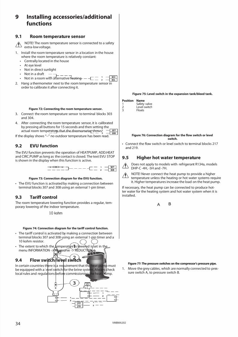
9.1 Room temperature sensor
⚠ NOTE! The room temperature sensor is connected to a safetyextra-low voltage.
1. Install the room temperature sensor in a location in the housewhere the room temperature is relatively constant:
• Centrally located in the house
• At eye level
• Not in direct sunlight
• Not in a draft
• Not in a room with alternative heating
2. Hang a thermometer next to the room temperature sensor inorder to calibrate it after connecting it.
Figure 72: Connecting the room temperature sensor.
3. Connect the room temperature sensor to terminal blocks 303
and 304.4. After connecting the room temperature sensor, it is calibrated
by pressing all buttons for 15 seconds and then setting theactual room temperature that the thermometer shows.
If the display shows “--” no outdoor temperature has been read.
9.2 EVU function
The EVU function prevents the operation of HEATPUMP, ADD.HEATand CIRC.PUMP as long as the contact is closed. The text EVU STOPis shown in the display when this function is active.
Figure 73: Connection diagram for the EVU function.
• The EVU function is activated by making a connection betweenterminal blocks 307 and 308 using an external 1-pin timer.
9.3 Tariff control The room temperature lowering function provides a regular, tem-porary lowering of the indoor temperature.
Figure 74: Connection diagram for the tariff control function.
• The tariff control is activated by making a connection between
terminal blocks 307 and 308 using an external 1-pin timer and a10 kohm resistor.
• The extent to which the temperature is lowered is set in themenu INFORMATION -> Heatcurve -> REDUCTION.
9.4 Flow switch/level switchIn certain countries there is a requirement that the heat pump mustbe equipped with a level switch for the brine system. Always check local rules and regulations before commissioning the heat pump.
Figure 75: Level switch in the expansion tank/bleed tank.
Position Name1 Safety valve2 Level switch3 Floats
Figure 76: Connection diagram for the flow switch or levelswitch.
• Connect the flow switch or level switch to terminal blocks 217and 219.
9.5 Higher hot water temperature
⚠ Does not apply to models with refrigerant R134a, modelsDHP-C -4H, -5H and -7H.
⚠
NOTE! Never connect the heat pump to provide a higher
temperature unless the heating or hot water systems requireit. Higher temperatures increase the load on the heat pump.
If necessary, the heat pump can be connected to produce hot-ter water for the heating system and hot water system when it isinstalled.
Figure 77: The pressure switches on the compressor’s pressure pipe.
1. Move the grey cables, which are normally connected to pres-sure switch A, to pressure switch B.
10 kohm
B A

8/3/2019 Dhp Install Vmbma202 En
http://slidepdf.com/reader/full/dhp-install-vmbma202-en 35/96
35VMBMA202
10 Start upNOTE! Read the safety instructions!
⚠ The installation may only be commissioned if the heatingsystem, water heater and brine system have been filled andbled. Otherwise the circulation pumps may be damaged.
⚠ If the installation is only to be run on auxiliary heating, firstensure that the heating system is filled and bled and that nei-ther the brine pump nor the compressor can be started. Thisis carried out by setting the operating mode to ADD.HEAT.
⚠ Any alarms that may occur in connection with the installationcan be fault-traced in the “Troubleshooting” section in theservice instructions.
10.1 Installation checklistBefore manual test operation check the following points:
Piping installation, heating system
• Pipe connections in accordance with the connection diagram
• Flexible hoses on the supply and return lines
• Surge tank on supply line
• Pipe insulation
• Strainer on return line, heating system
• Bleeding of the heating system
• All radiator valves fully open
• Expansion tank heating system (not included in the delivery)
• Safety valve for expansion tank (not included in the delivery)
• Filler cock, heating system (not included in the delivery)
• Leakage inspection
If a an external water heater is installed, also check:
• Exchange valve
• Safety valve for cold water (9 bar)
Electrical Installation
• Circuit-breaker
• Fuse protection
• Direction of rotation of the compressor
• Coolant pump
• At DHP-A, -AL, outdoor unit
• At DHP-A, -AL, defroster sensor
• Positioning of the outdoor sensor
• Control computer settings
If a an external water heater is installed, also check:
• Exchange valve
Brine system
• Expansion/bleed tank on the return line
• Safety valve for expansion tank
• Filler cock on the return line
• Insulation in the outside wall lead-in
• Other brine pipe insulation
• Bleeding of brine system
• Leakage inspection
10.2 Manual test Test operate and at the same time check the function of the testedcomponents.
Activate MANUAL TEST
1. Ensure that the main circuit breaker is on.
2. Select operating mode , in the menu INFORMATION ->OPERAT.->
3. Open the SERVICE menu by pressing for five seconds.
4. Set the value for MANUAL TEST to 2.
⚠ NOTE! Select position 2 to navigate away from the MANUAL TEST menu during ongoing test operation!
Test the brine pump
5. Start the brine system’s brine pump by setting the valueBRINEPUMP to 1.
6. Check that the brine pump is running by:
• listening
• putting a hand on the pump
• checking that the level in the expansion tank is stable. If the levelis not stable there is air in the system.
• listen for air
7. If the pump does not start see the section, “Starting circulationpumps manually”.
8. If there is air in the brine system, bleed according to section,“Bleeding the brine system”.
9. Stop the brine pump by setting the value to 0.
Test the circulation pump
10. Start the heating system circulation pump by setting the valueCIRC.PUMP to 1.
11. Check that the circulation pump is running by:
• listening
• putting a hand on the pump• listen for air
12. If the pump does not start see the section, “Starting circulationpumps manually”.
13. If there is air in the heating system, bleed according to section,“Bleeding the heating system”.
14. Stop the circulation pump by setting the value to 0.
Test the exchange valve
15. Activate the 3-way valve by setting the value VXV WARMWATERto 1.
16. Check that the arm on the 3-way valve changes position.
17. If the arm does not change position, see the “Troubleshooting”section in the service instructions.
Test the compressor
18. Start the circulation pump by setting the value CIRC.PUMP to 1
19. Start the heat pump compressor by setting the valueHEATPUMP to 1. At the same time as the value is set to 1 forHEATPUMP the brine pump starts.
⚠ NOTE! Risk of burns, the pipe can reach 70-80°C!

8/3/2019 Dhp Install Vmbma202 En
http://slidepdf.com/reader/full/dhp-install-vmbma202-en 36/96
36 VMBMA202
Figure 78: The pressure pipe should get hot during operation.
20. Check that:
• the compressor is running in the right direction by putting ahand on the pressure pipe and checking that it is hot.
• it sounds normal and there is no noise.
21. If the pipe does not get hot, or if it sounds abnormal, see the“Troubleshooting” section in the service instructions.
22. Stop the compressor by setting the value to 0.
23. Stop the brine pump by setting the value to 0.
24. Stop the circulation pump by setting the value to 0.
Testing the auxiliary heating power stages
25. Start the circulation pump by setting the value CIRC.PUMP to 1
26. Start the first auxiliary heating power stage by setting the valueADD.HEAT 1 to 1.
27. Check that the auxiliary heating power stage works by leav-ing the menu MANUAL TEST and going into the menuINFORMATION -> TEMPERATURE -> SUPPLY and check that thetemperature rises.
28. Return to the menu MANUAL TEST and stop ADD.HEAT 1 by set-ting the value back to 0.
29. Repeat steps 26 to 28 for ADD.HEAT 2 and ADD.HEAT 3.
30. Stop the circulation pump by setting the value to 0.
Test fuse protection
31. Start the circulation pump by setting the value CIRC.PUMP to 1
32. Start the compressor by setting the value HEATPUMP to 1.
33. At the same time, start the auxiliary heating power stages avail-able to check that the fuse protection can withstand full poweroperation.
34. Stop the auxiliary heating power stages and the compressor bysetting the value back to 0.
35. Stop the circulation pump by setting the value to 0.
Test the outdoor unit for DHP-A, -AL
36. Start the defroster shunt by setting the value SHUNT DEFR to 1.
37. Start the fan at low speed by setting the FAN L value to 1.Check that the fan runs at low speed.
38. Start the fan at high speed by setting the FAN H value to 1.Check that the fan runs at high speed.
Exit test operation
39. Set the value for MANUAL TEST to 0.
10.3 Commissioning
Starting circulation pumps manually
If any of the circulation pumps do not start, it may need to behelped as follows:
Figure 79: Bleed screw location.
1. Open and remove the bleed screw on the front of the pump.Normally a small amount of water comes out when it isremoved.
2. Insert a flat blade screwdriver and turn it in the direction of rotation of the pump (clockwise).
3. Reinstall the bleed screw with its rubber seal.
Adaptation to the heating system
Adjust the heat pump settings to the applicable heating system, forinstance an underfloor heating or radiator system. The delta tem-perature must be at least 8°C above the heat pump. The delta tem-perature should be 3-5°C for the brine system. If none of the deltatemperatures are reached, the flow of the circulation pumps mayneed adjusting depending on the applicable heating system.
Noise check
During transportation and installation there is a certain risk that theheat pump can be damaged, components may move or get bentand this can cause noise. Because of this it is important to check the heat pump when it has been installed and is ready to be com-missioned to ensure that everything seems in order. The heat pumpshould be run in both heating and hot water modes to ensure that
there is no abnormal noise. While doing this, check that there is noabnormal noise in other parts of the house.
Noise is produced from the outdoor unit when the fan is in opera-tion, check during that manual operation that there is no distur-bance in your own home as well as to any neighbours. A noise kit isavailable for purchase for the outdoor unit for DHP-A 10 and 12 if itis necessary to reduce the noise.
Select operating mode
Set the heat pump to the desired operating mode in the menuINFORMATION -> OPERAT. If necessary, set certain parameters inthe control computer, such as ROOM and CURVE.
10.4 Installing the front cover
⚠ NOTE! Take care not to damage the front cover!
1. Align the upper section of the front cover with both the sidechannels at the top of the unit and slide it carefully downwardsuntil it covers the entire front of the unit.
2. Tighten the screws.
10.5 After start up
⚠ NOTE! Remember that it takes time for the heat pump toheat a cold house. It is best to let the heat pump work at itsown pace and NOT raise or alter any values in the controlcomputer to try to heat it up more rapidly.
⚠NOTE! If there is an LP alarm in conjunction with installation
it usually means that there is air in the system. Normally thealarm disappears after a few days. If the alarm does not stopthe brine circuit must be bled and topped up.

8/3/2019 Dhp Install Vmbma202 En
http://slidepdf.com/reader/full/dhp-install-vmbma202-en 37/96
37VMBMA202
11 Customer informationAfter installation and test operation, the customer must beinformed about their new heat pump installation. Below is a check-list regarding the information that the installer must give the cus-tomer:
• The model of the heat pump that has been installed
• Run through the Maintenance instructions and show what it con-tains
• Describe the various operating modes and what they mean
• Describe the most common alarms and corrective actions
• Demonstrate how to navigate the control computer and whichsettings the customer can set themselves
• Demonstrate how to view history and operating times
• Show the pipe installation and go through the periodic mainte-nance actions that the customers must be aware of:- recommended pressure on manometers- fill the heating system- exercise safety valves- clean strainers
• Explain how the customer can fine adjust their existing heatingsystem according to the instructions in the maintenance instruc-tions
• The applicable warranties• Where the customer is to turn for servicing
• Finally, fill in the reference list at the back of the Maintenanceinstructions.

8/3/2019 Dhp Install Vmbma202 En
http://slidepdf.com/reader/full/dhp-install-vmbma202-en 38/96
38 VMBMA202
Service instructions12 The heat pump
12.1 Function descriptionA heat pump utilises the free energy found in a natural heat source, such as rock, ground, ground water or air. The heat pump can be com-pared to a reversed refrigerator. In a refrigerator, heat is transferred from the inside of the refrigerator to the outside. In a heat pump theheat that is stored in a heat source is transferred to the inside of the house. The heat pump uses the energy in the heat source and givesback two to three times more heat energy than what it uses in electrical energy. The heat pump is, therefore, a very environmentally friend-ly and economical way of heating a house.
In order for the heat pump to be able to retrieve heating energy from the heat source and transfer it to the heating system of the house,three separate fluid circuits are required.
The circuit that retrieves the heating energy from the heat source is called the brine circuit and it maintains a low outgoing temperature tobe heated by the heat source.
The next circuit is called the refrigerant circuit and is a closed circuit which takes the retrieves heating energy and transfers it to the last cir-cuit, the heat transfer fluid circuit.
The heat transfer fluid circuit holds the fluid that circulates in the heating system of the house and in the heat pump’s water heater.
The figure below shows how the different circuits work together in the transfer of heating energy.
Figure 80: Function principles of a heat pump.
1 A fluid (brine) filled hose is lowered into a lake, buried in the ground or lowered into bedrock. The brine obtains energy from the heatsource by the fluid temperature in the hose being heated a few degrees by the surrounding heat source. The fluid filled hose is alsoknown as a collector.
2 The brine is guided into the heat pump’s evaporator. The enclosed refrigerant in the refrigerant circuit is forced to boil as the pressurein the expansion valve drops and later evaporates to a gas in the evaporator. The energy produced during this process is released bythe slightly heated brine.
3 The refrigerant that now contains a large quantity of energy in the form of heat is transferred to the compressor, which both increasesits temperature and pressure.
4 The refrigerant then continues to the condenser. When condensing, the refrigerant supplies its heat energy to the heat transfer fluidcircuit. The refrigerant’s temperature decreases and returns to a liquid state.
5 The heat transfer fluid circuit transports the heat energy out to the water heater, radiator and the under floor heating system, whichheat up.
6 The refrigerant is then transported through the expansion valve where the pressure drops and the refrigerant starts to boil and thenthe process starts again.
12.2 Components The heat pump is a complete heat pump installation for heating and hot water. It has the market’s first compressor developed solely forheat pumps. It has an integrated 180 litre water heater and auxiliary heating. TWS stands for Tap Water Stratificator. This technology resultsin more effective heat transfer and more effective layering of the water in the water heater.
The heat pump is equipped with control equipment, which is controlled via a control panel.
Heat enters the house via a water borne heating system, a low temperature system. The heat pump supplies as much of the heat demand
as possible before auxiliary heating is engaged and assists. The heat pump unit consists of five basic units:
Expansion valve/pressure drop
Enclosedrefrigerant
Compressor/pressure increasing
Brine
Condenser
Evaporator
Heat transfer fluid circuit – is the circuit that contains
the water that transports the heat/energy to the heating
system and the water heater.
Refrigerant circuit – is the circuit that contains a chlorine
and freon free refrigerant which, inside the heat pump,
transfers the energy retrieved from the brine circuit
through evaporation, compression and condensation,
and supplies it to the heat transfer fluid circuit.
Brine circuit – is the circuit that contains an antifreeze
water based mix that obtains and transports energy from
the heat source to the heat pump. This circuit is also
known as the collector.
Rock, ground, groundwater or air
Heating system andwater heater

8/3/2019 Dhp Install Vmbma202 En
http://slidepdf.com/reader/full/dhp-install-vmbma202-en 39/96
39VMBMA202
1 Heat pump unit
• Scroll compressor
• Stainless steel heat exchanger
• Circulation pumps for brine and heating systems
• Valves and safety equipment for cooling systems and corresponding electrical components.
2 Water heater
• 180 litres
• Internal anti-corrosion protection with copper or stainless steel
• It does not have an anode, which makes it maintenance free
3 Exchange valve• The heated water either passes through to the heating system or to the water heater depending on
whether heating or hot water is to be produced
4 Auxiliary heat
• 9 kW electric heating element (4.5 kW at 230 V heat pump installation)
• Electric heating element control in maximum of three steps (five steps for DHP-A, -AL)
• Installed on the heating system’s supply line
• Covers the demand of extra energy if the heat pump’s capacity is exceeded
• Automatically connected if operating mode AUTO is selected.
5 Control equipment
• Control computer with graphic display
• Temperature sensors (outdoor, supply line, return line, brine and hot water)
• Room sensor (option)
The control equipment controls the heat pump unit’s included components (compressor, circulationpumps, auxiliary heaters and exchange valve) and determines when to start and stop the pump as well asproducing heat for the house or hot water.
12.3 Outdoor unit and defroster function, DHP-A, -AL
Figure 82: The figure shows DHP-AL which has a separate water heater.
The DHP-A and DHP-AL heat pumps are equipped with an outdoor unit that uses air as a heat source down to -20°C. The outdoor unit hasa coil where brine recovers free energy from the outside air. It also has a fan which increases the air flow through the coil. During operationthe coil is cooled by the energy exchange at the same time as the humidity causes it to become covered in frost. DHP-AL has an automaticfunction to defrost the coil using the produced heat energy. If necessary, a defrosting sequence starts which means the following:
• The defrosting sequence starts when the temperature of the brine reaches its set parameter for defrosting.
• The compressor is stopped so that the defrosting sequence should not load the compressor unnecessarily. On the other hand the com-pressor is not stopped when it produces hot water because the water heater is cooled when defrosting. The fan on the outdoor unit isstopped in conjunction with defrosting to shorten the time of defrosting.
1
4
3
5
2
Figure 81: Heat pump components.
8/3/2019 Dhp Install Vmbma202 En
http://slidepdf.com/reader/full/dhp-install-vmbma202-en 40/96
40 VMBMA202
• The shunt valve in the heat pump opens so that hot brine from the defrosting tank is mixed with the cold brine circulating to the out-door unit. The mixture has a temperature of about 15°C.
• The fifteen degree heated brine melts the frost on the outside of the battery at the same time as the liquid is cooled.
• When the brine is no longer cooled to temperatures below 11°C the battery is sufficiently defrosted.
• The shunt valve closes the flow of hot brine from the defrosting tank.
• Operation returns to normal.
12.4 Passive cooling function, DHP-C
Heat pump DHP-C is equipped with an extra heat exchanger to use the passive cooling effect from the brine. Because the temperature inthe collector (borehole or equivalent) is lower than the indoor temperature, the temperature difference can be exploited to cool the indoorair. At the same time the collector is charged with energy before the cold periods of the year.
DHP-C is a complete installation for heating, hot water and passive cooling where the control automatically ensures that the desired indoorclimate is reached. Because the DHP-C uses the same pipe system for heating and cooling, it is important to use a temperature when cool-ing that does not cause condensation on the pipe system. (If the system is not adapted to it.) Use of fan convectors is recommended.
12.5 Auxiliary heating, DHP-H, -L, -CIf the heat demand is greater than the heat pump’s capacity, the auxiliary heater engages automatically. The auxiliary heater is made up of an electric heating element on the supply line that has two outputs, ADD.HEAT 1 and ADD.HEAT 2, and can be controlled in three steps.
For three phase, 400V 3N, installations:
• Step 1 = ADD.HEAT 1 = 3 kW
• Step 2 = ADD.HEAT 2 = 6 kW
• Step 3 = ADD.HEAT 1 + ADD.HEAT 2 = 9 kWFor single phase, 230V 1N SP, installations:
• Step 1 = ADD.HEAT 1 = 1.5 kW
• Step 2 = ADD.HEAT 2 = 3 kW
• Step 3 = ADD.HEAT 1 + ADD.HEAT 2 = 4.5 kW
To calculate the total energy consumption, see the ”Settings- Calculating energy consumption” section.
In the event of an alarm, the auxiliary heater engages automatically.
12.6 Auxiliary heating DHP-A, -AL The auxiliary heater for 400V 3N heat pumps is made up of an electric heating element on the supply line that has three outputs, ADD.HEAT 1, ADD.HEAT 2 and ADD.HEAT 3, and can be controlled in five steps.
• Step 1 = ADD.HEAT 1 = 3 kW
• Step 2 = ADD.HEAT 2 = 6 kW• Step 3 = ADD.HEAT 1 + ADD.HEAT 2 = 9 kW
• Step 3 = ADD.HEAT 2 + ADD.HEAT 3 = 12 kW
• Step 5 = ADD.HEAT 1 + ADD.HEAT 2 + ADD.HEAT 3 = 15 kW
In the event of an alarm, the auxiliary heater engages automatically.
The last two steps, step 4 and step 5, cannot be activated when the compressor is running. There are further auxiliary heating steps: step+4 and step +5, which means that the compressor does not stop when they are activated. These can be selected on the condition that thebuilding where the heat pump is installed has a large heating requirement.
The auxiliary heater for 230V 1N heat pumps is made up of an electric heating element on the supply line that has two outputs, ADD.HEAT1 and ADD.HEAT 2, and can be controlled in three steps:
• Step 1 = ADD.HEAT 1 = 1.5 kW
• Step 2 = ADD.HEAT 2 = 3 kW
• Step 3 = ADD.HEAT 1 + ADD.HEAT 2 = 4.5 kW
In the event of an alarm, the auxiliary heater engages automatically.

8/3/2019 Dhp Install Vmbma202 En
http://slidepdf.com/reader/full/dhp-install-vmbma202-en 41/96
41VMBMA202
12.7 Water heater, DHP-H, -CDanfoss heat pumps DHP-H, -C, are supplied with an integrated 180 litre water heater.
Figure 83: Water heater in DHP-H and DHP-C.
Hot water production is prioritised ahead of heat production, i.e. no heat is produced if there is a hot water demand at the same time.
The temperature of the hot water cannot be adjusted. Normally, hot water production does not cease at a determined temperature butwhen the compressor’s operating pressure switch reaches its maximum operating pressure, which corresponds to a hot water temperatureof approximately 50-55°C.
Using a regular time interval, the water in the water heater is given extra heat by the integrated auxiliary heater to prevent the build up of bacteria (legionella function). The factory set time interval is seven days. When the legionella function is active the heat pump produces hotwater until the temperature for the start temperature sensor (5) has reached 60°. If the heat pump cannot raise the temperature sufficientlywithin 3.5 hours the control checks if there is any heating requirement, before legionella function is resumed.
In the control computer’s TEMPERATURE menu, a number of measured and calculated temperatures for the hot water and supply aredisplayed. The current hot water temperature (2) and the temperature of the supply line during heating and hot water production is dis-played. The temperature of the supply line often exceeds the maximum permitted hot water temperature, but usually during hot waterproduction.
12.8 Water heater, DHP-A, -AL The difference between DHP-A and DHP-AL’s water heaters and other DHP models is the defrost function of the outdoor unit, otherwisethey are the same and have the same functions.
The difference between a DHP-A and a DHP-AL is only that the hot water heater is integrated in DHP-A and that the water heater is exter-nally placed in a separate cabinet for DHP-AL.
The integrated 180 litre hot water heater has a defrosting tank (mantel) outside the heater that contains heated brine (approx 47 litres)which is used during defrosting.
Figure 84: Water heater for DHP-A and DHP-AL.
1 7 8
2
3
4
6
5
Position Name1 Hot water line
2 Temperature sensors3 Water heater4 TWS coil5 Start temperature sensor6 Return from TWS coil7 Filler pipe8 Flow line to TWS coil
Position Name1 Tap hot water2 Temperature sensors3 Defrosting tank 4 Water heater5 TWS coil6 Filler pipe7 Flow line to TWS coil8 Expansion outlet when outdoor
unit is positioned at high level
1 2
3
4
5

8/3/2019 Dhp Install Vmbma202 En
http://slidepdf.com/reader/full/dhp-install-vmbma202-en 42/96
42 VMBMA202
12.9 Important parameters
Heat production - calculating
The indoor temperature is adjusted by changing the heat pump’s heat curve, which is the control computer’s tool for calculating what thesupply temperature should be for water that is sent out in the heating system. The heat curve calculates the supply temperature depend-ing on the outdoor temperature. The lower the outdoor temperature, the higher the supply temperature. In other words, the supply tem-perature of the water fed to the heating system will increase exponentially as the outside air temperature falls.
The heat curve will be adjusted in connection with installation. It must be adapted later on, however, to obtain a pleasant indoor tempera-ture in any weather conditions. A correctly set heat curve reduces maintenance and saves energy.
CURVE
The control computer shows the value for CURVE by means of a graph in the display. You can set the heat curve by adjusting the CURVE value. The CURVE value indicates the supply temperature of the water to be sent out to the heating system at an outdoor temperature of 0°C.
Figure 85: Graph showing the set value 40 for CURVE.
At outdoor temperatures colder than 0°C, supply water hotter than 40°C is sent out to the heating system and at outdoor temperaturesgreater than 0°C, supply water cooler than 40°C is sent out.
Figure 86: Increasing or reducing the CURVE changes the slope of the curveIf you increase the CURVE value, the heat curve will become steeper and when you reduce it, it will become flatter.
The most energy efficient and cost effective setting is achieved by changing the CURVE value to adjust the temperature in the house to aneven and constant temperature. For a temporary increase or reduction, adjust the ROOM value instead.
Value for CURVE is 40...
Outdoor temperature
Supply temperature
...at zero degrees
Maximum supply tem-perature
Supply temperature
Outdoor temperature
Maximum supply tem-perature

8/3/2019 Dhp Install Vmbma202 En
http://slidepdf.com/reader/full/dhp-install-vmbma202-en 43/96
43VMBMA202
ROOM
If you wish to increase or reduce the indoor temperature, change the ROOM value. The difference between changing the ROOM value andthe CURVE value is that the system’s heat curve does not become steeper or flatter if the ROOM value is changed, which the curve becomesif the CURVE value changes, instead the entire heat curve is moved by 3°C for every degree change of the ROOM value. The reason that thecurve is adjusted 3° is that an approximate 3° increase in supply temperature is needed to increase the indoor temperature 1°.
Figure 87: Changing the ROOM value changes the heat curve upwards or downwards.
The relationship of the supply temperature to outdoor temperature will not be affected. The supply temperature will be increased orreduced by the same number of degrees all along the heat curve. I.E. the entire heat curve rises or drops instead of the curve gradient
changing. This method of adjusting the indoor temperatures must only be used for a temporary raise or drop. For long term increases or reductionsof the indoor temperature, the heat curve is adjusted instead.
Sometimes, at outdoor temperatures between -5°C and +5°C, part of the heat curve may need adjusting if the indoor temperature is notconstant. For this reason, the control system includes a function adjusting the curve at three outdoor temperatures: -5°C, 0°C and +5°C.
This function will allow you to increase or reduce the supply temperature, without affecting the heat curve, at three specific outdoor tem-peratures. If, for example, the outdoor temperature is -5°C, the supply temperature will change gradually between 0°C and -10°C, maximumadjustment being reached at -5°C. The figure below displays the adjusted CURVE -5. The adjustment can be seen on the graph in the formof a bump.
Figure 88: The adjusted curve at -5°C
You can choose to adjust the heat curve individually at three specified outdoor temperatures: -5°C, 0°C and +5°C. The supply temperaturecan be changed by plus/minus 5 degrees.
Supply temperature
Outdoor temperature
Maximum supply tem-perature
Supply temperature
Outdoor temperature
Local higher supply tem-perature at -5°

8/3/2019 Dhp Install Vmbma202 En
http://slidepdf.com/reader/full/dhp-install-vmbma202-en 44/96
44 VMBMA202
HEATSTOP
The HEATSTOP function automatically stops all production of radiator heat when the outdoor temperature is equal to, or higher than, thevalue entered for heat-stop.
When the heat-stop function is activated, the circulation pump will be turned off - except when hot water is being produced. The circula-tion pump will be "exercised" for 1 minute per day. The factory set value for activating heat-stop is an outdoor temperature of 17°C. If theheat-stop function is active, the outdoor temperature must drop 3°C when setting, before the heat-stop stops.
MIN and MAX
The MIN and MAX values are the lowest, respectively highest set point values that are allowed for the supply temperature.
Adjusting the minimum and maximum supply temperatures is particularly important if your home has under floor heating.If your house has under floor heating and parquet floors, the supply temperature must not exceed 45°C. Otherwise there is a risk that theparquet floors might be damaged. If you have under floor heating and stone tiles, the MIN value should be 22-25°C, even in summer whenno heating is required. This is to achieve a comfortable floor temperature.
If your house has a basement, the MIN value should be adjusted to a suitable temperature for the basement in summer. A condition formaintaining the heat in the basement in the summer is that all radiators have thermostat valves that switch off the heat in the rest of thehouse. It is extremely important that the heating system and the radiator valves are trimmed correctly. As it is usually the end customersthemselves who have to carry out trimming, remember to inform them how to carry it out correctly. Also remember that the value forHEATSTOP needs adjusting upwards for summer heating.
TEMPERATURES
The heat pump can display a graph showing the history of the various sensors’ temperatures and you can see how they have changed over60 measurement points in time. The time interval between the measurement points can be adjusted between one minute and one hour,factory setting is one minute.
History is available for all sensors, but only the set value is shown in the display for the room sensor. The integral value that may appear isthe heating system’s energy balance.
INTEGRAL
The heat demand in the house depends on the season and weather conditions and is not constant. The heat demand can be expressed astemperature difference over time and can be calculated giving an integral value as a result (heat demand). To calculate the integral value,the control computer uses several parameters.
A heat deficit is needed to start the heat pump, and there are two integral values, A1 and A2, which start the compressor and auxiliaryheater. During heat production, the deficit reduces and when the heat pump stops, the inertia in the system causes a surplus of heat.
The integral value is a measurement of the surface under the time axis and is expressed in degree minutes. The figure below shows the fac-tory settings for the integral values that the heat pump has. When the integral value has reached the set value for INTEGRAL A1, the com-pressor starts and if the integral value does not drop but continues to rise, the auxiliary heater starts when the integral value has reachedthe set value for INTEGRAL A2.
Figure 89: Starting and stopping heat pump operation based on integral values.
The integral value calculation stops during hot water production and during . Integral value calculation resumes two minutesafter completed hot water production to give the heating system time to stabilise the temperature.
More specific conditions for starting and stopping the heat pump are described in the “Operating conditions” chapter.
Heat surplusIntegral
INTEGRAL A1
Heat surplus
Heating deficit
Compressor start
(-60)
INTEGRAL A2
INTEGRAL A1
INTEGRAL A2
Auxiliary heater start
(-660)
Compressor stop
(≥0)
Auxiliary heater stop
(latest at -60)
Auxiliaryheater
CompressorNo operation No operation
Compressor start
(-60)
Auxiliary heater start
(-660)
Auxiliaryheater
Compressor
Time
Heat pumpoperation
(Heatdemand)

8/3/2019 Dhp Install Vmbma202 En
http://slidepdf.com/reader/full/dhp-install-vmbma202-en 45/96
45VMBMA202
HYSTERESIS
In order to start the heat pump in advance during sudden changes of the heat demand, there is a value, HYSTERESIS, which controls thedifference between the actual supply temperature, t
1and the calculated supply temperature, t
2. If the difference is the same or greater than
the set HYSTERESIS value (x), i.e. there is a heat demand, or the heat demand disappears, quicker than the usual integral calculation, theintegral value is forced to either the start value INTEGRAL A1 or to the stop value 0°min.
Figure 90: Conditions for HYSTERESIS to force the integral value to change.
HYSTERESIS(∆t) ≥ x
Compressor start
(-60)
Compressor stop
(0)
t1
t2
HYSTERESIS(∆t) ≥ x
TIMEINTEGRAL
SUPPLY TEMP.

8/3/2019 Dhp Install Vmbma202 En
http://slidepdf.com/reader/full/dhp-install-vmbma202-en 46/96
46 VMBMA202
DEFR CURVE, defrosting curve for DHP-A, -AL
To start defrosting the outdoor unit for DHP-A, -AL, the control computer makes a calculation using the temperature of the brine returnand the outdoor temperature.
What guides the calculation is a linear defrosting curve that can be set so that the heat pump and outdoor unit work optimally. The settingof three different values can be changed: DEFR CURVE 0 , DEFR CURVE –20 and OUTDOOR STOP. The defrosting sequence starts when thetemperature of the brine return reaches the set parameter value at an outdoor temperature somewhere along the set defrosting curve.
The two parameters that are mainly changed are DEFR CURVE 0 and DEFR CURVE -20. The numbers behind the DEFR CURVE display whatoutdoor temperature the setting is for, that is to say at 0°C for DEFR CURVE 0 and the temperature that is set for OUTDOOR STOP for DEFRCURVE -20. What DEFR CURVE -20 actually stands for is DEFR CURVE [ printed value for OUTDOOR STOP ].
Factory setting for OUTDOOR STOP is -20°C. At this outdoor temperature, compressor operation is stopped and the addition takes over. It isseldom that the value of OUTDOOR STOP needs to be changed, tests and operating cases have shown that -20°C operates very well as thestop temperature. In the text and figures below the value -20°C has been used for OUTDOOR STOP.
The control computer shows the value for DEFR CURVE 0 and DEFR CURVE –20 by means of a graph in the display.
Figure 91: Graph that shows how the value for DEFR CURVE 0 can be set.
The value for OUTDOOR STOP that is set means that the compressor will no longer be used for heating or hot water production if theoutdoor temperature is the same as or lower than the value. Heating and hot water production then occurs with the help of the auxiliaryheater.
The value for DEFR CURVE 0 is the temperature that the brine return is permitted to reach when a defrost must start at outdoor tempera-ture 0°C.
In the corresponding way the value for DEFR CURVE -20 is the temperature that the brine return has when a defrost should start at theset outdoor temperature for OUTDOOR STOP. The setting for DEFR CURVE –20 means that the value OUTDOOR STOP (-20°C) is reduced bybetween 1 and 8 degrees. This also determines how much lower the temperature for the brine return may be than -20°C in this case.
Figure 92: Graph that shows how the value for DEFR CURVE -20 can be set.
These three settings together create the defrosting curve and all three values have an effect on when defrosting will start, even if it is main-ly DEFR CURVE 0 and DEFR CURVE -20 that is changed.
Temperature, input brine line
Outdoor temperature
Adjustable interval for DEFR CURVE 0 isa brine return between -5°C and -15°Cat 0°C outdoor temperature
Set value forDEFR CURVE -20
Temperature, input brineline
Outdoor temperature
Adjustable value for DEFR CURVE -20 is1°C to 8°C lower than OUTDOOR STOP
Set value for OUTD OOR STOP, -20°C
Set value forDEFR CURVE 0

8/3/2019 Dhp Install Vmbma202 En
http://slidepdf.com/reader/full/dhp-install-vmbma202-en 47/96
47VMBMA202
13 Control computer
13.1 Function descriptionA control computer is used to automatically calculate the heat demand in the house where the heat pump is installed and to ensure thatthe correct amount of heat is produced and emitted where necessary. There are many different values (parameters) that must be referredto during the calculation of the heat demand. During installation use the control computer to set and change certain values that have tobe adapted according to the house demand. The control computer is also used during service to view alarms and history, and to check thevalue settings. The display window, keypad and an indicator are on the front of the control computer. It consists of a simple menu systemthat is used to navigate the desired settings and values.
Figure 93: Display, control buttons and indicator for the heat pump.
Use the four control buttons on the keypad to navigate the menus and increase or reduce the set values:
• An up button with a plus sign
• A down button with a minus sign
• A right button with a right arrow
• A left button with a left arrow
The display always shows the set ROOM value and the status of the heat pump.
There are two main menus that are used to affect the heat pump settings. The menus are designed for two categories of user, end custom-ers and installers, who make different settings in the control computer. For this reason the service menu is hidden from end customers.
Figure 94: The menus are reached via different button presses.
The main menu, INFORMATION, is opened by pressing the left or right buttons. From the INFORMATION menu you can open the sub menusto make settings for the heat pump.
For installation or service, the hidden menu, SERVICE, is used. This is opened by holding the left button depressed for five seconds. Fromthe service menu you can open sub menus to make advanced settings.
The symbols in the display areonly examples. Certain sym-bols cannot be displayed atthe same time.
ROOM 20°C(20°C)
NO DEMAND HEATOPERAT. AUTO
5s
INFORMATION SERVICE

8/3/2019 Dhp Install Vmbma202 En
http://slidepdf.com/reader/full/dhp-install-vmbma202-en 48/96
48 VMBMA202
13.2 Display The display of the control computer shows information about the heat pump’s operation, status and any alarms, in text form. The status,indicated by symbols, is also shown in the lower section which shows the heat pump’s active process.
Operating mode
Appears with applicable heat pump operating status text.
Operating mode Meaning
(OFF) The installation is fully switched off.
⚠ Remember that if the operating mode OFF is to be used for long periods duringthe winter, the water in the heating system in the installation must be drained, oth-erwise there is a risk of frost damage.
AUTO The heat pump and the auxiliary heater are automatically controlled by the control computer.
HEATPUMP The control computer is controlled so that only the heat pump unit (compressor) is al lowed to operate. In
this operating mode peak heating charging (legionella function) of the hot water will not be run because
additional heat must not be used.
ADD. HEAT The control computer only permits the auxiliary heater to be in operation. This operating mode can be
used when a new installation is being used, when the brine system is not ready for operation.
HOT WATER In this mode the heat pump only produces hot water, no heat goes to the heating system.
Symbols
Displays the operating status of the heat pump using symbols.Symbol Meaning
HP Indicates that the compressor is in operation.
LIGHTNING Indicates that the auxiliary heater is in operation. Number of auxiliary power stages indicated by digit.
HOUSE Indicates that the 3-way valve position is for heat production for the house.
TAP Indicates that the 3-way valve’s position is for hot water production.
F FLOW GUARD An “F” next to the symbol indicates that a flow guard is installed.CLOCK Indicates that tariff control is active.
TANK Indicates the level of hot water in the water heater. During charging, the tank is filled and filling starts at
the set start temperature. A lightning symbol by the symbol indicates peak heating charging (legionella
function).
SQUARE Either indicates that the operating pressure switch has deployed, or that the hot gas temperature has
reached its maximum temperature.
DEFROST Displayed if defrosting is active. (DHP-A, -AL)
FAN Displayed if the fan is active L=Low speed and H= High speed. (DHP-A, -AL)
COOLING Indicates Cooling. A indicates active cooling.
Text
Appears with applicable heat pump operating status text.
Message Meaning
ROOM Shows the set ROOM value. Standard value: 20°C.
If the accessory room sensor is installed it shows the actual temperature and the desired indoor tempe-
rature within brackets.

8/3/2019 Dhp Install Vmbma202 En
http://slidepdf.com/reader/full/dhp-install-vmbma202-en 49/96
49VMBMA202
Message Meaning
ERR PHASE SEQ. Alarm that indicates that there is an incorrect phase sequence to the compressor. Only display and only
the first 10 minutes.
HIGH RETURN Alarm that indicates that the high return temperature prevents the compressor’s operation.
START Indicates that there is a demand for heating production and that no start delay is active.
EVU STOP Indicates that the additional function EVU is active. This means that the heat pump is off as long as EVU
is active.
NO DEMAND HEAT Indicates that there is no heating production demand.
HIGHPRESS ERROR Alarm that indicates that the high pressure switch has deployed.
LOWPRESS ERROR Alarm that indicates that the low pressure switch has deployed.
MOTOR P ERROR Alarm that indicates that the motor protection has deployed.
BRINEFLOW LOW Appears if the accessory flow switch is installed. Alarm that indicates that the flow in the brine system
is low.
SENSOR Alarm that indicates a faulty sensor.
HEATPUMP START --MIN Indicates that there is a heating production demand and will start in the specified number of minutes.
HEATPUMP+ADD.HEAT Indicates that heat production is active with both compressor and auxiliary heater.
START_MIN Indicates that there is a demand for heating production but that a start delay is active.
ADD. HEAT Indicates that there is an auxiliary heater demand.
COOLING Displayed if cooling is passive.
COOLING A Displayed if cooling is active.
DEFROST Displayed if defrosting is active. (DHP-A, -AL)
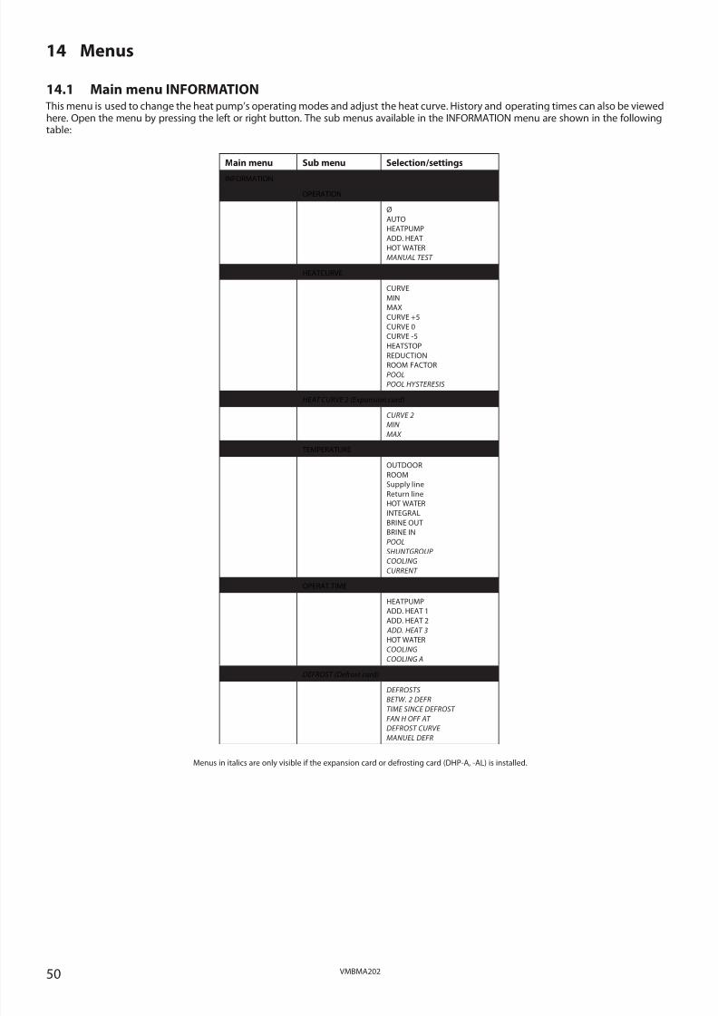
8/3/2019 Dhp Install Vmbma202 En
http://slidepdf.com/reader/full/dhp-install-vmbma202-en 50/96
50 VMBMA202
14 Menus
14.1 Main menu INFORMATION This menu is used to change the heat pump’s operating modes and adjust the heat curve. History and operating times can also be viewedhere. Open the menu by pressing the left or right button. The sub menus available in the INFORMATION menu are shown in the followingtable:
Main menu Sub menu Selection/settings
INFORMATION
OPERATION
Ø
AUTO
HEATPUMP
ADD. HEAT
HOT WATER
MANUAL TEST
HEATCURVE
CURVE
MIN
MAX
CURVE +5
CURVE 0
CURVE -5
HEATSTOP
REDUCTIONROOM FACTOR
POOL
POOL HYSTERESIS
HEAT CURVE 2 (Expansion card)
CURVE 2
MIN
MAX
TEMPERATURE
OUTDOOR
ROOM
Supply line
Return line
HOT WATER
INTEGRAL
BRINE OUT
BRINE INPOOL
SHUNTGROUP
COOLING
CURRENT
OPERAT.TIME
HEATPUMP
ADD. HEAT 1
ADD. HEAT 2
ADD. HEAT 3
HOT WATER
COOLING
COOLING A
DEFROST (Defrost card)
DEFROSTS
BETW. 2 DEFR
TIME SINCE DEFROST FAN H OFF AT
DEFROST CURVE
MANUEL DEFR
Menus in italics are only visible if the expansion card or defrosting card (DHP-A, -AL) is installed.

8/3/2019 Dhp Install Vmbma202 En
http://slidepdf.com/reader/full/dhp-install-vmbma202-en 51/96
51VMBMA202
Sub menu INFORMATION -> OPERATION
Used to select operating mode.
Menu selection Meaning Factory setting
(OFF) The installation is off. Any active alarms reset. -
AUTO Automatic operation with both heat pump and auxiliary heater permitted. If the number
of power stages for auxiliary heating are set to zero (SERVICE -> AUX.HEAT -> MAX STAGE)
only AUTO or OFF can be selected as operating mode.
-
HEATPUMP Operation with only heat pump permitted. NOTE! No peak heating charging (legionella
function) with only heat pump operation.
-
ADD. HEAT Operation with only auxiliary heater permitted. -
HOT WATER Operation with heat pump for hot water production and auxiliary heater during peak hea-
ting charging (legionella function).
-
MANUAL TEST Only appears when MANUAL TEST in the SERVICE menu is active. Outputs controlled
manually.
-
Sub menu INFORMATION -> HEAT CURVE
Used to change settings for the heat curve.
Menu selection Meaning Factory setting
CURVE Calculated supply temperature at 0°C outdoor temperature. Shown as a graph that also
shows MIN and MAX values.
40°C
(during under floor heating
30°C)(interval: 22°C / 56°C)
MIN Minimum permitted supply temperature, if the temperature for heat-stop has been
reached and the heat pump has stopped.
10°C
(interval: 10°C / 50°C)
MAX Maximum permitted supply temperature. 55°C
(during under floor heating
45°C)
(interval: 40°C / 85°C)
CURVE 5 Local increase or reduction of CURVE at an outdoor temperature of +5°C. Shown in the
graph for CURVE.
0°C (interval: -5°C / 5°C)
CURVE 0 Local increase or reduction of CURVE at an outdoor temperature of 0°C. Shown in the
graph for CURVE.
0°C (interval: -5°C / 5°C)
CURVE -5 Local increase or reduction of CURVE at an outdoor temperature of -5°C. Shown in the
graph for CURVE.
0°C (interval: -5°C / 5°C)
HEATSTOP Maximum outdoor temperature when heat production is permitted.
If HEAT STOP applies, the outdoor temperature must drop 3°C below the setting before
HEAT STOP stops.
17°C
(interval: OFF, 0°C / 40°C)
REDUCTION Only appears if the tariff control function has been activated. Lowering set room tempera-
ture. Active at 10 kohm connection at EVU input.
2°C (interval: 1°C / 10°C)
ROOM FACTOR Only displayed if an accessory Room temperature sensor is installed.
Determines how large an impact the room temperature is to have when calculating the
supply temperature. For underfloor heating we recommend a setting between 1-3 and for
radiator heating between 2-4.
2 (interval: 0 / 4)
(0 = no impact,
4 = large impact)
POOL
(Expansion card)
Only appears if POOL is selected. The temperature in the pool is controlled by a separate
sensor regardless of the heating and hot water system.
20°C
(interval: OFF, 5°C / 40°C)
POOL HYSTERESIS(Expansion card)
Only appears if POOL is selected. In simple terms, the POOL HYSTERESIS is the tempera-ture interval between start and stop for pool heating. If the difference between the actual
supply temperature to pool and the calculated supply temperature is too great, either the
integral value is set to start value A1 (the heat pump starts) or the value is set to 0 (stops
the heat pump).
2°C (interval: 1°C / 10°C)
Sub menu INFORMATION -> HEAT CURVE 2
The menu only applies if the expansion card is installed and only appears if shunt group sensor is connected and activated in menuSERVICE -> INSTALLATION -> SYSTEM -> SHUNTGROUP (Expansion card). Used to change settings for heat curve 2.
Menu selection Meaning Factory setting
CURVE 2 Calculated shunt group temperature at 0°C outdoor temperature. Shown as a graph that
also shows MIN and MAX values.
40°C
(interval: 22°C / 56°C)
MIN Minimum permitted shunt group temperature, if the temperature for heat-stop has not
been reached.
10°C
(interval: 10°C / 50°C)
MAX Maximum permitted shunt group temperature. 55°C
(interval: 15°C / 70°C)

8/3/2019 Dhp Install Vmbma202 En
http://slidepdf.com/reader/full/dhp-install-vmbma202-en 52/96
52 VMBMA202
Sub menu INFORMATION -> TEMPERATURE
Used to indicate the prevailing temperatures, history and set/calculated values. History can be accessed to view all the values by pressingthe right arrow to present a graph of the last 100 measurement points for the set time interval (SERVICE -> INSTALLATION -> LOGTIME). Inthe event of an alarm, history stops being logged until the alarm is reset by changing the operating mode to OFF.
Menu selection Meaning Factory setting
OUTDOOR Shows the actual outdoor temperature. -
ROOM Shows the actual set temperature. -
Supply line Shows the actual supply temperature. The calculated supply temperature to the heating
system group is within brackets.
During hot water production in operating mode ADD.HEAT the value for HOT
WATER STOPP + 5° is shown within brackets.
-
Return line Shows the actual return temperature. The stop temperature, MAX RETURN is within brack-
ets.
-
HOT WATER Shows the actual hot water temperature. -
INTEGRAL Shows the actual calculated value for integral. -
BRINE OUT Shows the actual temperature for the brine system’s supply line. -
BRINE IN Shows the actual temperature for the brine system’s return line. -
POOL
(Expansion card)
Only appears if POOL is selected. Shows the actual pool temperature. The set pool tempe-
rature is shown in brackets.
-
SHUNTGROUP
(Expansion card)
Only appears if SHUNTGROUP is selected. Shows the actual supply temperature. The cal-
culated supply temperature to the shunt group is within brackets.
-
COOLING
(Expansion card)
Only appears if COOLING is selected. Shows the actual supply temperature. The set point
value is shown in brackets.
-
CURRENT
(Expansion card)
Only appears if CURRENT LIMITER is selected. Shows the actual current consumption. The
set value for MAX CURRENT is shown between brackets.
-
Sub menu INFORMATION -> OPERAT. TIMEUsed to show the operating time for each component. Time given in hours.
Menu selection Meaning Factory setting
HEATPUMP Compressor operating time for both heating and hot water production. -
ADD. HEAT 1 Operating time auxiliary heater power stage 1 with full output 3 kW (VL). -
ADD. HEAT 2 Operating time auxiliary heater power stage 2 with full output 6 kW (VL). -
ADD.HEAT 3
(Defrost card)
Operating time auxiliary heater power stage 3 with full output 6 kW (VL). -
HOT WATER Operating time hot water with compressor. -
COOLING
(Expansion card)
Operating time passive cooling. -
COOLING ACTIVE
(Expansion card)
Operating time active cooling. -
Sub menu INFORMATION -> DEFROST (DHP-A, -AL)
The menu applies to DHP-A, -AL with defroster card and only appears if OUTDOOR AIR in the SERVICE -> INSTALLATION -> SYSTEM -> HEATSOURCE menu is selected. Used to obtain information about outdoor unit defrosting and to make certain settings.
Menu selection Meaning Factory setting
DEFROSTS Total number of defrosts carried out. -
BETW. 2 DEFR The operating time of the compressor in minutes between the 2 last defrosts. -
TIME SINCE DEFROST The operating time of the compressor in minutes since last defrost. -
FAN H OFF AT Fan high speed is deactivated at this temperature and low speed is activated. 12°C
(interval: 10°C / 20°C)
DEFROST CURVE Here, the angle of the defrost curve can be changed using the right-hand arrow and by
either pressing + or – (Change the start temperature for defrost).
-10°C
(interval: -13°C / -7°C)
MANUEL DEFR By using the right-hand arrow + or -, defrost can be started manually (shunts +20°C for 10
minutes).
0 (interval: 0 / 1)
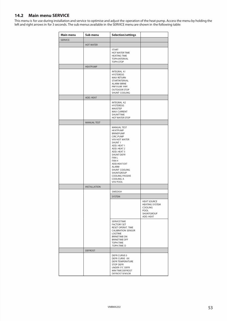
8/3/2019 Dhp Install Vmbma202 En
http://slidepdf.com/reader/full/dhp-install-vmbma202-en 53/96
53VMBMA202
14.2 Main menu SERVICE This menu is for use during installation and service to optimise and adjust the operation of the heat pump. Access the menu by holding theleft and right arrows in for 3 seconds. The sub menus available in the SERVICE menu are shown in the following table:
Main menu Sub menu Selection/settings
SERVICE
HOT WATER
START
HOT WATER TIME
HEATING TIME TOPH.INTERVAL
TOPH.STOP
HEATPUMP
INTEGRAL A1
HYSTERESIS
MAX RETURN
STARTINTERVAL
ALARM BRINE
PRESSURE PIPE
OUTDOOR STOP
SHUNT COOLING
ADD. HEAT
INTEGRAL A2
HYSTERESIS
MAXSTEP
MAX CURRENTSHUNTTIME
HOT WATER STOP
MANUAL TEST
MANUAL TEST
HEATPUMP
BRINEPUMP
CIRC.PUMP
VXV HOT WATER
SHUNT 1
ADD. HEAT 1
ADD. HEAT 2
ADD. HEAT 3
SHUNT DEFR
FAN L
FAN H
ADD.HEAT EXT
ALARM
SHUNT COOLING
SHUNTGROUP
COOLING PASSIVE
COOLING A
VXV POOL
INSTALLATION
SWEDISH
SYSTEM
HEAT SOURCE
HEATING SYSTEM
COOLING
POOL
SHUNTGROUP
ADD. HEAT
SERVICETIME
FACTORY SETRESET OPERAT. TIME
CALIBRATION SENSOR
LOGTIME
BRINETIME ON
BRINETIME OFF
TOPH.TIME
TOPH.TIME D
DEFROST
DEFR CURVE 0
DEFR CURVE -XX
DEFR TEMPERATURE
STOP DEFR
UNDER 5°C DEFR
MIN TIME DEFROST
DEFROST SENSOR
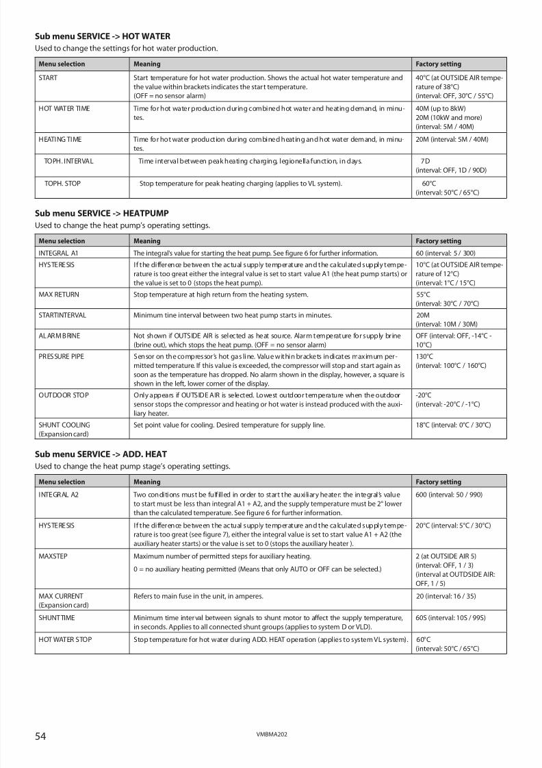
8/3/2019 Dhp Install Vmbma202 En
http://slidepdf.com/reader/full/dhp-install-vmbma202-en 54/96
54 VMBMA202
Sub menu SERVICE -> HOT WATER
Used to change the settings for hot water production.
Menu selection Meaning Factory setting
START Start temperature for hot water production. Shows the actual hot water temperature and
the value within brackets indicates the start temperature.
(OFF = no sensor alarm)
40°C (at OUTSIDE AIR tempe-
rature of 38°C)
(interval: OFF, 30°C / 55°C)
HOT WATER TIME Time for hot water production during combined hot water and heating demand, in minu-
tes.
40M (up to 8kW)
20M (10kW and more)
(interval: 5M / 40M)
HEATING TIME Time for hot water production during combined heating and hot water demand, in minu-
tes.
20M (interval: 5M / 40M)
TOPH. INTERVAL Time interval between peak heating charging, legionella function, in days. 7D
(interval: OFF, 1D / 90D)
TOPH. STOP Stop temperature for peak heating charging (applies to VL system). 60°C
(interval: 50°C / 65°C)
Sub menu SERVICE -> HEATPUMP
Used to change the heat pump’s operating settings.
Menu selection Meaning Factory setting
INTEGRAL A1 The integral’s value for starting the heat pump. See figure 6 for further information. 60 (interval: 5 / 300)
HYSTERESIS If the difference between the actual supply temperature and the calculated supply tempe-
rature is too great either the integral value is set to start value A1 (the heat pump starts) or
the value is set to 0 (stops the heat pump).
10°C (at OUTSIDE AIR tempe-
rature of 12°C)
(interval: 1°C / 15°C)
MAX RETURN Stop temperature at high return from the heating system. 55°C
(interval: 30°C / 70°C)
STARTINTERVAL Minimum tine interval between two heat pump starts in minutes. 20M
(interval: 10M / 30M)
ALARM BRINE Not shown if OUTSIDE AIR is selected as heat source. Alarm temperature for supply brine
(brine out), which stops the heat pump. (OFF = no sensor alarm)
OFF (interval: OFF, -14°C -
10°C)
PRESSURE PIPE Sensor on the compressor’s hot gas line. Value within brackets indicates maximum per-
mitted temperature. If this value is exceeded, the compressor will stop and start again as
soon as the temperature has dropped. No alarm shown in the display, however, a square is
shown in the left, lower corner of the display.
130°C
(interval: 100°C / 160°C)
OUTDOOR STOP Only appears if OUTSIDE AIR is selected. Lowest outdoor temperature when the outdoor
sensor stops the compressor and heating or hot water is instead produced with the auxi-liary heater.
-20°C
(interval: -20°C / -1°C)
SHUNT COOLING
(Expansion card)
Set point value for cooling. Desired temperature for supply line. 18°C (interval: 0°C / 30°C)
Sub menu SERVICE -> ADD. HEAT
Used to change the heat pump stage’s operating settings.
Menu selection Meaning Factory setting
INTEGRAL A2 Two conditions must be fulfilled in order to start the auxiliary heater: the integral ’s value
to start must be less than integral A1 + A2, and the supply temperature must be 2° lower
than the calculated temperature. See figure 6 for further information.
600 (interval: 50 / 990)
HYSTERESIS If the difference between the actual supply temperature and the calculated supply tempe-
rature is too great (see figure 7), either the integral value is set to start value A1 + A2 (theauxiliary heater starts) or the value is set to 0 (stops the auxiliary heater ).
20°C (interval: 5°C / 30°C)
MAXSTEP Maximum number of permitted steps for auxiliary heating.
0 = no auxiliary heating permitted (Means that only AUTO or OFF can be selected.)
2 (at OUTSIDE AIR 5)
(interval: OFF, 1 / 3)
(interval at OUTDSIDE AIR:
OFF, 1 / 5)
MAX CURRENT
(Expansion card)
Refers to main fuse in the unit, in amperes. 20 (interval: 16 / 35)
SHUNTTIME Minimum time interval between signals to shunt motor to affect the supply temperature,
in seconds. Applies to all connected shunt groups (applies to system D or VLD).
60S (interval: 10S / 99S)
HOT WATER STOP Stop temperature for hot water during ADD. HEAT operation (applies to system VL system). 60°C
(interval: 50°C / 65°C)

8/3/2019 Dhp Install Vmbma202 En
http://slidepdf.com/reader/full/dhp-install-vmbma202-en 55/96
55VMBMA202
Sub menu SERVICE -> MANUAL TEST
Used to manually test and test operate the heat pump’s components or signal outputs.
Menu selection Meaning Factory setting
MANUAL TEST Setting options for manual test.
0 = deactivate manual test
1 = activate manual test
2 = activate manual test with option of navigating from the SERVICE menu to check that
the temperatures rise.
-
HEATPUMP 0 = stop heat pump, does not stop started brine pump
1 = start heat pump, also starts brine pump.
NOTE! The heat pump cannot be started in the event of an active alarm.
-
BRINEPUMP 0 = stop brine pump
1 = start brine pump
-
CIRC: PUMP 0 = stop circulation pump
1 = start circulation pump
-
VXV HOT WATER 0 = heating mode for 3-way valve
1 = hot water mode for 3-way valve
-
SHUNT 1 - = closes shunt (applies to D-system)
0 = shunt unaffected
+ = opens shunt (applies to D-system)
-
ADD. HEAT 1 0 = stop auxiliary heat step 1
1 = start auxiliary heat step 1
-
ADD. HEAT 2 0 = stop auxiliary heat step 2
1 = start auxiliary heat step 2
-
ADD. HEAT 3 (DHP-A, -AL)
(Defrost card)
0 = stop auxiliary heat step 3
1 = start auxiliary heat step 3
-
SHUNT DEFR (DHP-A, -AL)
(Defrost card)
- = opens flow from the defrost tank
0 = shunt unaffected
+ = closes the flow from the defrost tank
-
FAN L
(Defrost card)
0 = stop fan
1 = start fan with low speed
-
FAN H
(Defrost card)
0 = stop fan
1 = start fan with high speed
-
ADD.HEAT EXT (DHP-A, -AL)
(Defrost card)
0 = 0V on terminal block 283
1 = control voltage 230V on terminal block 283
-
ALARM
(Expansion card)
0 = stop signal on output External alarm
1 = start signal on output External alarm
-
SHUNT COOLING
(Expansion card)
- = shuts shunt
0 = shunt unaffected
+ = opens shunt
-
SHUNTGROUP
(Expansion card)
- = shuts shunt
0 = shunt unaffected
+ = opens shunt
-
COOLING PASSIVE
(Expansion card)
0 = stop passive cooling
1 = start passive cooling (brine pump starts and shunt cooling regulates to set point value)
-
COOLING ACTIVE
(Expansion card)
0 = stop active cooling
1 = start active cooling (brine pump and compressor starts, shunt cooling regulates to setpoint value)
-
VXV POOL
(Expansion card)
0 = normal mode for exchange valve
1 = pool mode for exchange valve
-

8/3/2019 Dhp Install Vmbma202 En
http://slidepdf.com/reader/full/dhp-install-vmbma202-en 56/96
56 VMBMA202
Sub menu SERVICE -> INSTALLATION
Used for settings that are set during installation
Menu selection Meaning Factory setting
SWEDISH Language setting for the control computer. SWEDISH
(SVENSKA
NORSK,
SUOMI,
DEUTSCH,
NEDERLANDS,
ENGLISH,FRANCAIS
POLSKI
DANSK)
SYSTEM
NOTE! The menu selection
in the SYSTEM menu varies
depending on the selected
values. Tip: start in the top
menu and work downwards.
Sub menu SERVICE -> INSTALLATION -> SYSTEM:
Menu selec tion Meaning
HEAT SOURCE GROUND OR ROCK
OUTSIDE AIR (Defrost card)
HEATING SYSTEM VL-SYSTEM
D-SYSTEM
VLD-SYSTEM (appears if OUTSIDE AIR is selected)
COOLING
(Expansion card)
COOLING PASSIVE: OFF/EXTERNAL/INTEGRATED IN HP
COOLING ACTIVE: OFF/EXTERNAL
ROOM SENSOR: 0/1 (Appears if room sensor is installed)
(0=controls to a constant value, 1=controls to the value that the room sensor has)
POOL
(Expansion card)
ON/OFF
SHUNTGROUP
(Expansion card)
ON/OFF
When ON, HEAT CURVE 2 is activated in the INFORMATION menu.
ADD. HEAT CONTROLLED CP: only OFF
0-10V: OFF / EXTERNAL ADDITIONAL HEATER (Expansion card)
FLOW SENSOR: ON/OFF
CURRENT LIMITER: ON/OFF(Expansion card)
PHASE FAULT: OFF / PHASE READING
SERVICETIME NOTE! Only used for test operation. Simulates time 60 times as fast, which means that the
waiting times are eliminated during test operation.
0 = deactivates SERVICETIME
1 = activates SERVICETIME which speeds up the control computer’s integral calculation
and start delay by 60 times.
-
FACTORY SET 0 = starting point, the value returns to zero after a change
R = reset factory settings for radiator system
G = rest factory settings for under floor heating
-
RESET OPERAT. TIME 0 = no reset of operation times
1 = reset operation times to zero
-
CALIBRATION SENSOR Following sensors are in the installation:
OUTDOOR
Supply line
Return line
HOT WATERBRINE OUT
BRINE IN
DEFR SENSOR
0 (interval: -5°C / 5°C)
0 (interval: -5°C / 5°C)
0 (interval: -5°C / 5°C)
0 (interval: -5°C / 5°C)0 (interval: -5°C / 5°C)
0 (interval: -5°C / 5°C)
-5°C (interval: -5°C / 5°C)
EXTERNAL INFLUENCE (these parameters affect all sensors except the outdoor sensor. The
parameter compensates for the external influence on the sensor that is mounted in the
heat pump.
5
(interval: 0 / 20)
LOGTIME Time interval between collection points of temperature history in minutes. The history
graphs always show the 60 last collection points, which means that the graphs can display
history from 1 hour up to 60 hours ago.
(The function is not active if there is an active alarm).
1M (interval: 1M / 60M)
BRINETIME ON Switch on delay for compressor, in seconds. 30S (at internal passive coo-ling 90S)
(interval: 10S / 90S)
BRINETIME OFF Switch off delay for brine pump, in seconds. 30S (interval: 10S / 60S)
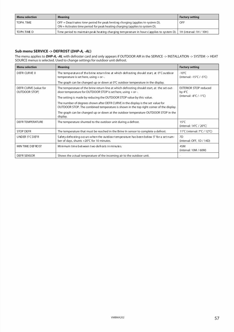
8/3/2019 Dhp Install Vmbma202 En
http://slidepdf.com/reader/full/dhp-install-vmbma202-en 57/96
57VMBMA202
Sub menu SERVICE -> DEFROST (DHP-A, -AL)
The menu applies toDHP-A, -AL
with defroster card and only appears if OUTDOOR AIR in the SERVICE -> INSTALLATION -> SYSTEM -> HEATSOURCE menus is selected. Used to change settings for outdoor unit defrost.
Menu selection Meaning Factory setting
DEFR CURVE 0 The temperature of the brine return line at which defrosting should start, at 0°C outdoor
temperature is set here, using + or -.
The graph can be changed up or down at 0°C outdoor temperature in the display.
-10°C
(interval: -15°C / -5°C)
DEFR CURVE [value for
OUTDOOR STOP]
The temperature of the brine return line at which defrosting should start, at the set out-
door temperature for OUTDOOR STOP is set here, using + or -.
The setting is made by reducing the OUTDOOR STOP value by this value.
The number of degrees shown after DEFR CURVE in the display is the set value for
OUTDOOR STOP. The combined temperature is shown in the top right corner of the display.
The graph can be changed up or down at the outdoor temperature OUTDOOR STOP in the
display.
EXTERIOR STOP reduced
by 4°C
(interval: -8°C / -1°C)
DEFR TEMPERATURE The temperature shunted to the outdoor unit during a defrost. 15°C
(interval: 14°C / 20°C)
STOP DEFR The temperature that must be reached in the Brine In sensor to complete a defrost. 11°C (interval: 7°C / 12°C)
UNDER 5°C DEFR Safety defrosting occurs when the outdoor temperature has been below 5° for a set num-
ber of days, shunts +20°C for 10 minutes.
7D
(interval: OFF, 1D / 14D)
MIN TIME DEFROST Minimum time between two defrosts in minutes. 45M
(interval: 10M / 60M)
DEFR SENSOR Shows the actual temperature of the incoming air to the outdoor unit. -
Menu selection Meaning Factory setting
TOPH. TIME OFF = Deactivates time period for peak heating charging (applies to system D).
ON = Activates time period for peak heating charging (applies to system D).
OFF
TOPH.TIME D Time period to maintain peak heating charging temperature in hours (applies to system D). 1H (interval : 1H / 10H)

8/3/2019 Dhp Install Vmbma202 En
http://slidepdf.com/reader/full/dhp-install-vmbma202-en 58/96
58 VMBMA202
15 Operating conditionsIf there is a demand for both heat production and hot water production, it switches between heating and hot water according to the seattime for HEATING TIME and HOT WATER TIME.
15.1 Starting heat production
Heat pump (compressor)
1. The integral value is less than or equivalent to what is set in INTEGRAL A1 and
2. at least 5 minutes have passed since the heat pump stopped and
3. the time since the previous start, set to START INTERVAL, has run out and4. the operating pressure switch is closed (=1) and
5. if HEAT-STOP stops and
6. if OUTDOOR STOP stops and
7. if the brine temperature is greater than the activated ALARM BRINE (factory setting: OFF) or
8. if the set value for HYSTERESIS is reached the integral value is forced to the value for INTEGRAL A1, which fulfils point 1.
Auxiliary heat
9. The integral value is less than or equivalent to the sum of INTEGRAL A1 + INTEGRAL A2 and
10. the actual temperature on the supply line is at least 3°C lower than the calculated supply temperature or
11. if the set value for HYSTERESIS is reached the integral value is forced to the value for INTEGRAL A1 + INTEGRAL A2, which fulfils point 9.
Auxiliary heater step 4 (12 kW) and 5 (15 kW ) are only activated when the temperature is -21°C or colder. These two steps are never acti-vated when the compressor is in operation. (Only applies to DHP-A, -AL).
15.2 Stopping heat production
Heat pump (compressor)
1. The integral value is greater or equivalent to 0°min (degree minutes) or
2. the return temperature is greater than, or the same as, the set maximum return temperature or
3. when the operating pressure switch has been open (=0) for more than 5 seconds or
4. if the pressure pipe sensor has reached its maximum permitted temperature or
5. if the outdoor temperature is greater or the same as HEAT-STOP or
6. if the outdoor temperature is lower than or the same as OUTDOOR STOP or
7. if the brine temperature is lower than or the same as the activated ALARM BRINE (factory setting: OFF) or
8. if the set value for HYSTERESIS is reached the integral value is forced to 0°min, which fulfils point 1.
9. If defrosting starts, the compressor stops and remains inactive during the defrosting period (Only applies to DHP-A, -AL).Auxiliary heat
10. The integral value is greater than the set value for INTEGRAL A1 or
11. the actual temperature on the supply line is 2°C greater than the calculated supply temperature.
15.3 Starting hot water production
Heat pump (compressor)
1. The hot water temperature is less than or the same as the set value for START or
2. hot water temperature within 2°C from the set start value for hot water production at end of heating production and
3. no active alarms that block hot water production.
Auxiliary heat
4. If OUTDOOR STOP is activated, the compressor stops automatically when the outdoor temperature is lower than or the same as the setvalue, the hot water is then produced by the auxiliary heater.
The auxiliary heater is not normally used to produce hot water but the following exceptions apply for the VL system:
• The auxiliary heater is in operation at the same time as the compressor when hot water production was started.
• Operating mode ADD. HEAT is selected.
• Peak heating charging (legionella function). The auxiliary heater connects 2 minutes after hot water production is started if ADD. HEATmode is not selected, peak heating charging is not delayed.
15.4 Stopping hot water production
Heat pump (compressor)
1. When the operating pressure switch has been open (=0) for more than 5 seconds (40 seconds for the first two minutes after start of hotwater production) or
2. if the pressure pipe sensor has reached its maximum permitted temperature or
3. the maximum time of 45 minutes has run out, after this time the heating demand is checked for 5 minutes.

8/3/2019 Dhp Install Vmbma202 En
http://slidepdf.com/reader/full/dhp-install-vmbma202-en 59/96
59VMBMA202
Auxiliary heatFor VL systems stop occurs when:
4. operating mode ADD. HEAT is selected and the temperature is the same as the value set for HOT WATER STOP or
5. when AUTO or HOT WATER is selected and the temperature is the same as the set value for HOT WATER STOP and the auxiliary heaterproduces hot water in cases when OUTDOOR STOP stops or
6. the set value for TOPH.STOP is reached during peak heating charging (legionella function).

8/3/2019 Dhp Install Vmbma202 En
http://slidepdf.com/reader/full/dhp-install-vmbma202-en 60/96
60 VMBMA202
16 Troubleshooting
16.1 Alarm listShown in display in the event of an alarm. To reset alarms 1-5, set the operating mode to OFF or cut the power supply.
Message Meaning
HIGHPRESS ERROR Tripped high pressure switch. Compressor stopped. No hot water production.
LOWPRESS ERROR Tripped low pressure switch. Compressor stopped. No hot water production.
MOTOR P ERROR Deployed motor protection (Over current relay compressor). Compressor stopped. No hot water pro-
duction.
BRINE OUT Brine supply does not exceed set temperature. Compressor stopped. No hot water production. Not
normally activated.
BRINEFLOW LOW Flow sensor not active during last start. Compressor stopped. No hot water production.
ADD. HEAT Overheating protection deployed. No auxiliary heating active.
SENSOR OUTDOOR Fault in outside sensor. Zero degrees used for calculations.
SENSOR FRONT Incorrect supply line sensor. Everything stops except circulation pump.
SENSOR RETURN Return sensor fault. Return temperature = Supply line – 5 is used. Calculated supply temperature limi-
ted to maximum 45°C.
SENSOR HOT WATER Fault on sensor for start temperature. No hot water production.
SENSOR DEFROST Defrost sensor fault. Heat and hot water production is controlled from the outdoor sensor’s value ins-
tead. (Applies to DHP-A, -AL)
MS FAN Deployed motor protection for outdoor unit fan. Compressor stopped. No hot water production.
(Applies to DHP-A, -AL)
SENSOR COOLING Sensor fault. Cooling function stops.
16.2 Measurement points
Conversion table for sensors
NOTE! When reading the resistance of the sensors, the sensor leads must first be disconnected from the control equipment.
Outdoor sensor Other sensors
°C kiloohm °C kiloohm
-30 1884 0 66.3
-25 1443 5 52.4
-20 1115 10 41.8
-15 868 15 33.5
-10 681 20 27.1
-5 538 25 22.0
0 428 30 18.0
5 343 35 14.8
10 276 40 12.2
15 224 45 10.1
20 183 50 8.5
25 150 55 7.1
30 124 60 6.0
35 103 65 5.0
40 86 70 4.2
75 3.7
80 3.1
85 2.7
90 2.3
95 2.0
1. First measure the sensor including the cable.
2. Then measure the sensor only.

8/3/2019 Dhp Install Vmbma202 En
http://slidepdf.com/reader/full/dhp-install-vmbma202-en 61/96
61VMBMA202
16.3 Check points
Temperatures
Name Values
Condensing temperature 0.5 – 1.5 °C above supply line temperature
Evaporation temperature 7 - 8 °C lower than incoming brine
Overheating 4 - 8 K temperature difference
Radiator circuit 5 - 10 K temperature difference
Brine circuit 2 - 5 K temperature difference
Overheating R407C 4K ±1 K
Expansion valve factory setting
Name Setting
Danfoss TUBE R404A, 4.2 kW From fully closed position, screw 3 turns out
Danfoss TUBE R404A, 5.6 kW From fully closed position, screw 5.5 turns out
Danfoss TUBE R404A, 8.4 kW From fully closed position, screw 5 turns out
Danfoss TUBE R404A, 12.0 kW From fully closed position, screw 5.25 turns out
Danfoss TUBE R404A, 15.3 kW From fully closed position, screw 2.75 turns outDanfoss TUBE R407C, 11.0 kW From fully closed position, screw 6.25 turns out
Danfoss TUBE R407C, 17.0 kW From fully closed position, screw 5.5 turns out
Break pressure pressure switches
Refrigerant Pressostat Break pressure
R134a
(Only applies for
certain models of
DHP-C)
Low pressure switch 0.03 MPa
Operating pressostat 1.80 MPa
High pressure switch 2.45 MPa
R404A
(Only applies toDHP-A, -AL)
Low pressure switch 0.08 MPa
Operating pressure switch A 2.65 MPa
Operating pressure switch B 2.85 MPa
High pressure switch 3.10 MPa
R407C Low pressure switch 0.08 MPa
Operating pressure switch A 2.65 MPa
Operating pressure switch B 2.85 MPa
High pressure switch 3.10 MPa

8/3/2019 Dhp Install Vmbma202 En
http://slidepdf.com/reader/full/dhp-install-vmbma202-en 62/96
62 VMBMA202
16.4 Operational problems
ALARM. . . . . . . . . . . . . . . . . . . . . . . . . . . . . . . . . . . . . . . . . . . . . . . . . . . . . . . . . . . . . . . . . . . . . . . . . . . . . . . . . . . . . . . . . . . . . . . . . . . . . . . . . . . . . . . . . . . . . . . .62Problem – Alarm LP (low pressure pressure switch). . . . . . . . . . . . . . . . . . . . . . . . . . . . . . . . . . . . . . . . . . . . . . . . . . . . . . . . . . . . . . . . . . . . . . . . . . . . . . . . . . . 62Problem – Alarm HP (high pressure pressure switch) . . . . . . . . . . . . . . . . . . . . . . . . . . . . . . . . . . . . . . . . . . . . . . . . . . . . . . . . . . . . . . . . . . . . . . . . . . . . . . . . . 64Problem – Alarm MS (motor protection . . . . . . . . . . . . . . . . . . . . . . . . . . . . . . . . . . . . . . . . . . . . . . . . . . . . . . . . . . . . . . . . . . . . . . . . . . . . . . . . . . . . . . . . . . . . . . 65Problem – Alarm sensor (all) . . . . . . . . . . . . . . . . . . . . . . . . . . . . . . . . . . . . . . . . . . . . . . . . . . . . . . . . . . . . . . . . . . . . . . . . . . . . . . . . . . . . . . . . . . . . . . . . . . . . . . . . . 66Problem – Incorrect phase sequence. . . . . . . . . . . . . . . . . . . . . . . . . . . . . . . . . . . . . . . . . . . . . . . . . . . . . . . . . . . . . . . . . . . . . . . . . . . . . . . . . . . . . . . . . . . . . . . . . 66Problem – Alarm TS (addition) . . . . . . . . . . . . . . . . . . . . . . . . . . . . . . . . . . . . . . . . . . . . . . . . . . . . . . . . . . . . . . . . . . . . . . . . . . . . . . . . . . . . . . . . . . . . . . . . . . . . . . . 66Problem – Alarm Brine out. . . . . . . . . . . . . . . . . . . . . . . . . . . . . . . . . . . . . . . . . . . . . . . . . . . . . . . . . . . . . . . . . . . . . . . . . . . . . . . . . . . . . . . . . . . . . . . . . . . . . . . . . . . 67Problem – Alarm Brine flow low. . . . . . . . . . . . . . . . . . . . . . . . . . . . . . . . . . . . . . . . . . . . . . . . . . . . . . . . . . . . . . . . . . . . . . . . . . . . . . . . . . . . . . . . . . . . . . . . . . . . . . 67
Problem – Operating pressure switch open alternatively high hot gas temperature . . . . . . . . . . . . . . . . . . . . . . . . . . . . . . . . . . . . . . . . . . . . . . . . . . . 67
LEAKAGE. . . . . . . . . . . . . . . . . . . . . . . . . . . . . . . . . . . . . . . . . . . . . . . . . . . . . . . . . . . . . . . . . . . . . . . . . . . . . . . . . . . . . . . . . . . . . . . . . . . . . . . . . . . . . . . . . . . . . .68Problem – Leak fluid side . . . . . . . . . . . . . . . . . . . . . . . . . . . . . . . . . . . . . . . . . . . . . . . . . . . . . . . . . . . . . . . . . . . . . . . . . . . . . . . . . . . . . . . . . . . . . . . . . . . . . . . . . . . . 68
NOISE . . . . . . . . . . . . . . . . . . . . . . . . . . . . . . . . . . . . . . . . . . . . . . . . . . . . . . . . . . . . . . . . . . . . . . . . . . . . . . . . . . . . . . . . . . . . . . . . . . . . . . . . . . . . . . . . . . . . . . . . . 69Problem – Noise problem in the radiator system . . . . . . . . . . . . . . . . . . . . . . . . . . . . . . . . . . . . . . . . . . . . . . . . . . . . . . . . . . . . . . . . . . . . . . . . . . . . . . . . . . . . . 69Problem – Loud compressor noise . . . . . . . . . . . . . . . . . . . . . . . . . . . . . . . . . . . . . . . . . . . . . . . . . . . . . . . . . . . . . . . . . . . . . . . . . . . . . . . . . . . . . . . . . . . . . . . . . . . 70Problem – Shrieking whistling noise . . . . . . . . . . . . . . . . . . . . . . . . . . . . . . . . . . . . . . . . . . . . . . . . . . . . . . . . . . . . . . . . . . . . . . . . . . . . . . . . . . . . . . . . . . . . . . . . . 70Problem – Noise – miscellaneous . . . . . . . . . . . . . . . . . . . . . . . . . . . . . . . . . . . . . . . . . . . . . . . . . . . . . . . . . . . . . . . . . . . . . . . . . . . . . . . . . . . . . . . . . . . . . . . . . . . . 70
HOT WATER . . . . . . . . . . . . . . . . . . . . . . . . . . . . . . . . . . . . . . . . . . . . . . . . . . . . . . . . . . . . . . . . . . . . . . . . . . . . . . . . . . . . . . . . . . . . . . . . . . . . . . . . . . . . . . . . . . .71Problem – Temperature and/or quantity . . . . . . . . . . . . . . . . . . . . . . . . . . . . . . . . . . . . . . . . . . . . . . . . . . . . . . . . . . . . . . . . . . . . . . . . . . . . . . . . . . . . . . . . . . . . . 71
HEATING COMFORT . . . . . . . . . . . . . . . . . . . . . . . . . . . . . . . . . . . . . . . . . . . . . . . . . . . . . . . . . . . . . . . . . . . . . . . . . . . . . . . . . . . . . . . . . . . . . . . . . . . . . . . . . . . 72Problem – Too cold . . . . . . . . . . . . . . . . . . . . . . . . . . . . . . . . . . . . . . . . . . . . . . . . . . . . . . . . . . . . . . . . . . . . . . . . . . . . . . . . . . . . . . . . . . . . . . . . . . . . . . . . . . . . . . . . . . 72Problem – Too hot . . . . . . . . . . . . . . . . . . . . . . . . . . . . . . . . . . . . . . . . . . . . . . . . . . . . . . . . . . . . . . . . . . . . . . . . . . . . . . . . . . . . . . . . . . . . . . . . . . . . . . . . . . . . . . . . . . . 74
OTHER . . . . . . . . . . . . . . . . . . . . . . . . . . . . . . . . . . . . . . . . . . . . . . . . . . . . . . . . . . . . . . . . . . . . . . . . . . . . . . . . . . . . . . . . . . . . . . . . . . . . . . . . . . . . . . . . . . . . . . . .75Problem – The heat pump runs and runs but never stops . . . . . . . . . . . . . . . . . . . . . . . . . . . . . . . . . . . . . . . . . . . . . . . . . . . . . . . . . . . . . . . . . . . . . . . . . . . . . 75Problem – Runs on electric heating element . . . . . . . . . . . . . . . . . . . . . . . . . . . . . . . . . . . . . . . . . . . . . . . . . . . . . . . . . . . . . . . . . . . . . . . . . . . . . . . . . . . . . . . . . 76Problem – The auxiliary heater is in operation but not the compressor . . . . . . . . . . . . . . . . . . . . . . . . . . . . . . . . . . . . . . . . . . . . . . . . . . . . . . . . . . . . . . . . 76Problem – The heat pump consumes too much energy. . . . . . . . . . . . . . . . . . . . . . . . . . . . . . . . . . . . . . . . . . . . . . . . . . . . . . . . . . . . . . . . . . . . . . . . . . . . . . . 77Problem – Auxiliary heater cuts in too soon . . . . . . . . . . . . . . . . . . . . . . . . . . . . . . . . . . . . . . . . . . . . . . . . . . . . . . . . . . . . . . . . . . . . . . . . . . . . . . . . . . . . . . . . . . 79Problem – Short operating times despite heating demand . . . . . . . . . . . . . . . . . . . . . . . . . . . . . . . . . . . . . . . . . . . . . . . . . . . . . . . . . . . . . . . . . . . . . . . . . . . 80Problem – Connection of external AH . . . . . . . . . . . . . . . . . . . . . . . . . . . . . . . . . . . . . . . . . . . . . . . . . . . . . . . . . . . . . . . . . . . . . . . . . . . . . . . . . . . . . . . . . . . . . . . . 80
OUTDOOR UNIT . . . . . . . . . . . . . . . . . . . . . . . . . . . . . . . . . . . . . . . . . . . . . . . . . . . . . . . . . . . . . . . . . . . . . . . . . . . . . . . . . . . . . . . . . . . . . . . . . . . . . . . . . . . . . . .81Problem – Noise/loud noise . . . . . . . . . . . . . . . . . . . . . . . . . . . . . . . . . . . . . . . . . . . . . . . . . . . . . . . . . . . . . . . . . . . . . . . . . . . . . . . . . . . . . . . . . . . . . . . . . . . . . . . . . 81Problem – Defrosting problems. . . . . . . . . . . . . . . . . . . . . . . . . . . . . . . . . . . . . . . . . . . . . . . . . . . . . . . . . . . . . . . . . . . . . . . . . . . . . . . . . . . . . . . . . . . . . . . . . . . . . . 81Problem – Build-up of ice under and around the outdoor unit . . . . . . . . . . . . . . . . . . . . . . . . . . . . . . . . . . . . . . . . . . . . . . . . . . . . . . . . . . . . . . . . . . . . . . . . 81Problem – Water run-off by the outdoor unit, risk of moisture problems in house foundations . . . . . . . . . . . . . . . . . . . . . . . . . . . . . . . . . . . . . . . . . 81
ALARM
Problem – Alarm LP (low pressure pressure switch)
Cause Troubleshooting Remedy
1. Blocked strainer on the brine circuit. Check that the strainer is not blocked. Clean the strainer if necessary.
2. Air in the brine circuit. Listen for air in the heat pump and brine circuit. Bleed the brine circuit according to the instal-
lation instructions.
3. Closed taps, main tap or filler cock on the brine
circuit.
Check that the shut-off cock/any other taps are open. Open closed taps.
4. The circulation pump for the brine circuit isdefective or has jammed.
Check:• That the circulation pump spins.
• That the shut-off valves are open.
• That the strainer is not blocked.
• That no air is in the heating system.
The circulation pump may have jammed, if so, open the bleed screw and try to release
the paddle wheel using a screwdriver for
example.
Open closed valves or taps.
Check, and, if necessary, clean the strainer.
If necessary, bleed the heating system accor-
ding to the installation instructions
5. Cable break or loose cable to low pressure
pressure switch.
• Check that both cables are connected on the pres-
sure switch.
• Using the buzzer, check that there are no cable
breaks. In order to do this, disconnect the cables from
the pressure switch and circuit board.
If a cable has come loose, connect it.
If there is a cable break, replace the cable.
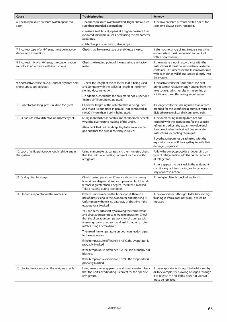
8/3/2019 Dhp Install Vmbma202 En
http://slidepdf.com/reader/full/dhp-install-vmbma202-en 63/96
63VMBMA202
Cause Troubleshooting Remedy
6. The low pressure pressure switch opens too
soon.
• Incorrect pressure switch installed. Higher break pres-
sure than intended. See marking.
• Pressure switch fault, opens at a higher pressure than
indicated (mark pressure). Check using the manometer
apparatus.
• Defective pressure switch, always open.
If the low pressure pressure switch opens too
soon or is always open, replace it.
7. Incorrect type of anti-freeze, must be in accor-
dance with instructions.
Check that the correct type of anti-freeze is used. If the incorrect type of anti-freeze is used, the
entire system must be drained and refilled
with a new mixture.
8. Incorrect mix of anti-freeze, the concentration
must be in accordance with instructions.
Check the freezing point of the mix using a refracto-
meter.
If the mixture is not in accordance with the
instructions, it must be remixed in an external
container. This is because the fluids do not mix
with each other well if one is filled directly into
the system.
9. Short active collector, e.g. short or dry bore hole,
short surface soil collector.
• Check the length of the collector that is being used
and compare with the collector length in the dimen-
sioning documentation.
• In addition, check that the collector is not suspended
”in free air” if boreholes are used.
If the active collector is too short, the heat
pump cannot receive enough energy from the
heat source , which results in it requiring an
addition to cover the energy requirement.
10. Collector too long, pressure drop too great. Check the length of the collector that is being used
and that it is connected in parallel (not connected in
series) if more than 1 coil is being used.
If a longer collector is being used than recom-
mended for the specific heat pump, it must be
divided on several parallel connected coils.
11. Expansion valve defective or incorrectly set. Using manometer apparatus and thermometer check
what the overheating reading of the unit is.
Also check that bulb and capillary tube are undama-
ged and that the bulb is correctly installed.
If the overheating reading does not cor-
respond with the instructions for the specific
refrigerant, adjust the expansion valve until
the correct value is obtained. See separate
instructions for cooling techniques.
If overheating cannot be adjusted with the
expansion valve or if the capillary tube/bulb is
damaged, replace it.
12. Lack of refrigerant, not enough refrigerant in
the system.
Using manometer apparatus and thermometer, check
that the unit’s overheating is correct for the specific
refrigerant.
Follow the correct procedure (depending on
type of refrigerant) to add the correct amount
of refrigerant.
If there appears to be a leak in the refrigerant
circuit, carry out leak tracing and any neces-sary corrective action.
13. Drying filter blockage. Check the temperature difference above the drying
filter. A one degree difference is permissible. If the dif-
ference is greater than 1 degree, the filter is blocked.
Take a reading during operation.
If the drying filter is blocked, replace it.
14. Blocked evaporator on the water side. If there is no strainer in the brine circuit, there is a
risk of dirt sticking in the evaporator and blocking it.
Unfortunately there is no easy way of checking if the
evaporator is blocked.
You can carry out a test by allowing the compressor
and circulation pumps to remain in operation. Check
that the circulation pumps work (for circ.pumps with
a venting screw, unscrew it and feel if the pump rotor
rotates using a screwdriver).
Then read the temperature on both connection pipes
to the evaporator:
If the temperature difference is <1°C, the evaporator is
probably blocked.
If the temperature difference is 2-6°C, it is probably not
blocked.
If the temperature difference is >6°C, the evaporator is
probably blocked.
If the evaporator is thought to be blocked, try
flushing it. If this does not work, it must be
replaced
15. Blocked evaporator on the refrigerant side. Using manometer apparatus and thermometer, check
that the unit’s overheating is correct for the specific
refrigerant.
If the evaporator is thought to be blocked by
oil for example, try blowing nitrogen through
it to release the oil. If this does not work, it
must be replaced

8/3/2019 Dhp Install Vmbma202 En
http://slidepdf.com/reader/full/dhp-install-vmbma202-en 64/96
64 VMBMA202
Problem – Alarm HP (high pressure pressure switch)
Cause Troubleshooting Remedy
1. Blocked strainer in the heating system. Check that the strainer is not blocked. Clean the strainer if necessary.
2. Air in the heating system. Listen for air in the heat pump and heating system. Bleed the heating system circuit according to
the installation instructions.
3. Closed or partially closed thermostats/valves in
the heating system.
Check that the thermostats/valves in the heating
system are open.
Open closed thermostats/valves.
4. The circulation pump that is defective or has
jammed.
Is there voltage to the circulation pump? In the control computer’s manual test menu
check that the circulation pump is active.Check if there is voltage to the circulation
pump, if there is, and it does not run, the
circulation pump is jammed. If this is the
case, open the bleed screw and try to release
the paddle wheel using a screwdriver for
example (Does not apply to heat pumps in
the Optimum series).
If there is no voltage to the circulation pump,
check if there is voltage from the control
computer, see wiring diagram. If there is
voltage from the control computer, check the
components between the control computer
and circulation pump.
If a component is defective, replace it.
5. Shut-off main tap in heating system. Check that the main tap is open. Open closed main tap.
6. Cable break or loose cable to high pressure
pressure switch.
• Check that both cables are connected on the pres-
sure switch.
• Using the buzzer, check that there are no cable
breaks. In order to do this, disconnect the cables from
the pressure switch and circuit board.
If a cable has come loose, connect it.
If there is a cable break, replace the cable.
7. The operating pressure switch does not open. • Incorrect pressure switch installed. Same or higher
break pressure than high pressure pressure switch.
See marking.
• Pressure switch fault, opens at a higher pressure
than indicated (mark pressure). Check using the
manometer apparatus.
• Defective pressure switch, never opens.
If the operating pressure switch does not
open, replace it.
8. The high pressure pressure switch opens too
soon.
• Incorrect pressure switch installed. As low or lower
break pressure than operating pressure switch. See
marking.
• Pressure switch fault, opens at a lower pressure than
indicated (mark pressure). Check using the manome-
ter apparatus.
• Defective pressure switch, always open.
If the high pressure pressure switch opens
too soon or is always open, replace it.
9. External system shunt that closes on time set-
ting.
Check for shunts or valves in the system, which are
timer-controlled, that close down the entire or too
large a part of the heating system.
Always ensure that there is a sufficiently large
water volume for the heat pump to work
against, i.e. for the heat to give off its heat to.
10. Incorrectly facing non-return valve with too
high opening pressure.
• Check the system’s direction of flow and that the
non-return valve is turned the correct way.
• Check that the heat pump’s external available pres-
sure exceeds the non-return valve’s opening pressure.
If the non-return valve is facing the wrong
way, turn it.
If the non-return valve has too great an ope-
ning pressure, replace it.
11. Large pressure drop in the heating system. • Dirt in the heating system.
• Closed or partially closed thermostats/valves in the
heating system.
• Under dimensioned pipe system. Check that the
HP’s external available pressure exceeds the system
pressure drop.
If necessary, clean/flush the heating system.
Open closed thermostats/valves.
If there is not sufficient pressure equipment,
the heating system can be adjusted accor-
ding to the system solution for large pressure
drop.
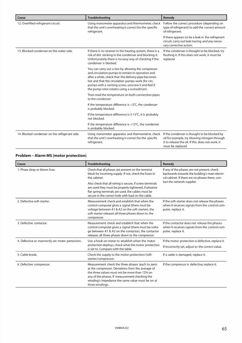
8/3/2019 Dhp Install Vmbma202 En
http://slidepdf.com/reader/full/dhp-install-vmbma202-en 65/96
65VMBMA202
Cause Troubleshooting Remedy
12. Overfilled refrigerant circuit. Using manometer apparatus and thermometer, check
that the unit’s overheating is correct for the specific
refrigerant.
Follow the correct procedure (depending on
type of refrigerant) to add the correct amount
of refrigerant.
If there appears to be a leak in the refrigerant
circuit, carry out leak tracing and any neces-
sary corrective action.
13. Blocked condenser on the water side. If there is no strainer in the heating system, there is a
risk of dirt sticking in the condenser and blocking it.
Unfortunately there is no easy way of checking if thecondenser is blocked.
You can carry out a test by allowing the compressor
and circulation pumps to remain in operation and
after a while, check that the delivery pipe becomes
hot and that the circulation pumps work (for circ.
pumps with a venting screw, unscrew it and feel if
the pump rotor rotates using a screwdriver).
Then read the temperature on both connection pipes
to the condenser:
If the temperature difference is <3°C, the condenser
is probably blocked.
If the temperature difference is 3-13°C, it is probably
not blocked.If the temperature difference is >13°C, the condenser
is probably blocked.
If the condenser is thought to be blocked, try
flushing it. If this does not work, it must be
replaced
14. Blocked condenser on the refrigerant side. Using manometer apparatus and thermometer, check
that the unit’s overheating is correct for the specific
refrigerant.
If the condenser is thought to be blocked by
oil for example, try blowing nitrogen through
it to release the oil. If this does not work, it
must be replaced
Problem – Alarm MS (motor protection)
Cause Troubleshooting Remedy
1. Phase drop or blown fuse. Check that all phases are present on the terminal
block for incoming supply. If not, check the fuses in
the cabinet.
Also check that all wiring is secure, if screw terminals
are used they must be properly tightened, if phoenix
flat spring terminals are used, the cables must be
secure in the correct hole with load on the cable.
If any of the phases are not present, check
backwards towards the building’s main electri-
cal cabinet. If there are no phases there, con-
tact the network supplier.
2. Defective soft-starter. Measurement check and establish that when the
control computer gives a signal (there must be
voltage between A1 & A2 on the soft-starter), the
soft-starter releases all three phases down to the
compressor.
If the soft-starter does not release the phases
when it receives signals from the control com-
puter, replace it.
3. Defective contactor. Measurement check and establish that when the
control computer gives a signal (there must be volta-
ge between A1 & A2 on the contactor), the contactor
releases all three phases down to the compressor.
If the contactor does not release the phases
when it receives signals from the control com-
puter, replace it.
4. Defective or incorrectly set motor protection. Use a hook-on meter to establish when the motorprotection deploys, check what the motor protection
is set to. Compare with the table.
If the motor protection is defective, replace it.
If incorrectly set, adjust to the correct value.
5. Cable break. Check the supply to the motor protection//soft-
starter/compressor.
If a cable is damaged, replace it.
6. Defective compressor. Measurement check the three phases (each to zero)
at the compressor. Deviations from the average of
the three values must not be more than 12% on
any of the phases. If measurement checking the
winding’s impedance the same value must be on all
three windings.
If the compressor is defective, replace it.

8/3/2019 Dhp Install Vmbma202 En
http://slidepdf.com/reader/full/dhp-install-vmbma202-en 66/96
66 VMBMA202
Problem – Alarm sensor (all)
Cause Troubleshooting Remedy
Sensor fault alternatively cable fault. • When reading the resistance of the sensors, the sen-
sor leads must first be disconnected from the control
equipment or terminal block.
• First take a reading from the sensor including cable
and check against the ohm table in the Measurement
points section.
• If the read off value does not correspond with the
table, only measure the sensor and check the ohm
table in the Measurement points section.
If the sensor gives a correct value, the cable
is defective.
If the sensor does not give a correct value,
the sensor is defective.
Problem – Incorrect phase sequence
Cause Troubleshooting Remedy
The incoming phases have the incorrect sequen-
ce (only applies to 3-phase heat pumps).
• If the text ERR PHASE SEQ appears in the display
when the heat pump is powered, (only appears in the
first 10 minutes) this means that the phases have the
incorrect sequence.
• When the compressor is running, check the delivery
pipe temperature by feeling the delivery pipe that
should be hot (not just warm) even a little distancefrom the compressor if the phases are correctly
sequenced.
• When the compressor runs with the phases incor-
rectly sequenced a strange noise may be heard (loud,
rattling) when the compressor runs backwards.
If the phases are in the incorrect order, switch
two incoming phases at the main terminal
block and recheck according to the trou-
bleshooting window.
Problem – Alarm TS (addition)
Cause Troubleshooting Remedy
1. The overheating protection has tripped. Check if the overheating protection has tripped. If the overheating protection has tripped,
reset it.
2. Phase drop.
The alarm occurs when 230 V is not registered
between incoming L2 on the circuit board and
zero on block 220.
• Check if the overheating protection has tripped.
• Check if any cables at the circuit board or overheating
protection are loose or damaged.
If the overheating protection has tripped,reset it.
If the cables are loose/damaged, secure or
replace them.
3. Overheating protection fault, cannot be reset. Press the reset button, measurement check for 230 V
on the incoming and outgoing connections.
If the overheating protection is defective,
replace it.
4. Flow sensor fault. Check what the flow sensor shows, is it a plausible/
actual value?
Measure the resistance of the sensor, check against
the ohm table in the Measurement points section.
If the sensor is defective, replace it.
5. No or insufficient circulation in the heating
system.
• That the strainer is not blocked.
• That no air is in the heating system.
The circulation pump may have jammed, if
so, open the bleed screw and try to release
the paddle wheel using a screwdriver for
example.
Open closed valves or taps.
Check, and, if necessary, clean the strainer.
If necessary, bleed the heating system accor-
ding to the installation instructions.
6. The submersible tube in the electric heating
element is against the coils.
Check what the flow temperature is when the over-
heating protection trips. It normally trips at about
95°C.
The submersible tube can be prised out
slightly from the coils using a screwdriver
or similar. The submersible tube must be
vertical.
Problem – Alarm Brine out

8/3/2019 Dhp Install Vmbma202 En
http://slidepdf.com/reader/full/dhp-install-vmbma202-en 67/96
67VMBMA202
Cause Troubleshooting Remedy
1. Defective sensor. Check what the sensor shows, is it a plausible/actual
value?
Measure the resistance of the sensor, check against
the ohm table in the Measurement points section.
If the sensor is defective, replace it.
2. Brine temperature too low. Check the set value on ALARM BRINE in the heat
pump’s control computer.
The alarm is triggered when the temperature
on BRINE OUT is as low or lower than the set
value on ALARM BRINE. In the factory setting
this function is inactive.
Problem – Alarm Brine flow low
Cause Troubleshooting Remedy
1. Incorrect system selected in the control com-
puter.
If the system does not contain a flow switch but
the control computer is set for the system with
flow switch, this alarm occurs.
In the menu SYSTEM, check which is selected. If the incorrect system is selected , change it.
2. Insufficient flow. • Check whether the ground water pump is running?
• Check the flow switch.
• Calibration/setting the flow switch.
• Blocked exchanger?
The ground water pump must start and run
together with the heat pump’s integrated
brine pump.Check against the wiring diagram that the
flow switch is correctly connected.
Check that the flow switch is set for the cor-
rect working range according to the flow
switch instructions.
If the exchanger is blocked, clean or replace it.

8/3/2019 Dhp Install Vmbma202 En
http://slidepdf.com/reader/full/dhp-install-vmbma202-en 68/96
68 VMBMA202
Problem – Operating pressure switch open alternatively high hot gas temperature
(indicated by med in the display’s lower left corner)
Cause Troubleshooting Remedy
1. The operating pressure switch does not close
again.
1. Switch off the main switch for the heat pump,
wait until the compressor has been stationary for
at least 15 minutes.
2. Disconnect the two cables on the pressure
switch, using a buzzer check if the pressure
switch is closed.
If the pressure switch is closed, bridge the pres-
sure switch cables temporarily and switch on
the current to the heat pump again. If there is an
indication in the display this means that the
pressure switch is fault-free and the problem is in
the wiring or in the circuit board.
If the pressure switch is open, try carefully tap-
ping the head of the pressure switch with a
screwdriver and using the buzzer test to see if it
has closed again.
Replace the pressure switch if it appears to jam
repeatedly.
2. Sensor fault, shows >120°C Check what the sensor shows, is it a plausible/
actual value?
Measure the resistance of the sensor, check
against the ohm table in the Measurement points
section.
If the sensor is defective, replace it.
3. Hot gas temperature too high. Check the set value on DELIVERY PIPE in the heat
pump’s control computer (factory setting 120°C)
The symbol appears when the delivery pipe tem-
perature is as high or greater than the set value
for DELIVERY PIPE.
4. Overheating too high. Using manometer apparatus and thermometer
check what the overheating reading of the unit is.
Also check that bulb and capillary tube are unda-
maged and that the bulb is correctly installed.
If the overheating reading does not correspond
with the instructions for the specific refrigerant,
adjust the expansion valve until the correct value
is obtained. See separate instructions for cooling
techniques.
If overheating cannot be adjusted with the
expansion valve or if the capillary tube/bulb is
damaged, replace it.
5. Lack of refrigerant, not enough refrigerant in
the system.
Using manometer apparatus and thermometer,
check that the unit’s overheating is correct for the
specific refrigerant.
Follow the correct procedure (depending on
type of refrigerant) to add the correct amount of
refrigerant.
If there appears to be a leak in the refrigerant
circuit, carry out leak tracing and any necessarycorrective action. If leak tracer is not available,
brush soap water on the suspected leak and look
for bubbles. Also check for oil as this can come
out from the refrigerant circuit.
LEAKAGE
Problem – Leak fluid side
Cause Troubleshooting Remedy
1. Insufficiently tightened connections. Locate the leak. • Tighten the connection and check that it is
sealed
• If it is still not sealed, replace the entire connec-
tion and support sleeve (only at soft pipes)
2. Cracked nut or connection. Locate the leak. Replace nut or connection.
3. Defective gasket or O-ring. Locate the leak. Replace the gasket or O-ring.
4. There is no overflow pipe connected to the
safety valve(s).
Establish which safety valve does not have an
overflow pipe.
Install an overflow pipe according to the appli-
cable norms.
5. Filler valve between incoming cold water and
heating system not closed or leaking.
Check whether water continuously leaks from
the safety valve on the expansion vessel on the
hot side.
Try closing the filler valve and see i f water stops
dripping from the safety valve, if not, replace the
filler valve.

8/3/2019 Dhp Install Vmbma202 En
http://slidepdf.com/reader/full/dhp-install-vmbma202-en 69/96
69VMBMA202
Cause Troubleshooting Remedy
6. No condensation drain to heat pump’s drip
tray.
Check that condensation drain is installed and
correctly connected.
Install the condensation drain that runs out into
the floor drain.
7. Lack of condensation insulation on cold water
pipe and/or brine pipe.
Establish where the condensation is coming
from.
The brine pipe must always be insulated. In the
event of problems with condensation on the cold
water pipes, insulate them. Condensation often
accumulates in joints and angled sections of the
insulation. Improve the insulation.
8. Leak at soldered joints. Locate the leak. Drain the system of fluid, repair the leak. If
the leak is on the connection pipe to the heatexchanger, also drain the refrigerant side.
9. Leak at the condenser’s drain cock. 1. Check that the valve is completely closed.
2. Check that the sealed cover is sealed.
If the sealed cover is not sealed, replace the sea-
led cover or the entire drain tap.
10. Leak at the condenser’s bleed valve. Check that it is completely closed. If it is fully closed and still leaks, replace it.
11. Leak at soldered joint on water heater. Locate the leak. If there is a leak at the soldered joint, replace the
water heater.
12. Associated leak on the water heater. • Establish whether water continuously leaks from
the safety valve on the expansion vessel on the
hot side.
• Establish whether water continuously leaks from
the safety valve on the cold side.
If the water heater has a leak, replace it.
13. Associated leakage in the condenser. • Check for lack of refrigerant in the unit.• Check by smelling by safety valve on the hot
side, open the valve and check.
If the condenser has a leak, replace it.
14. Anti-freeze is forced out of the safety valve on
the expansion tank (brine system).
During the winter, water surrounding the hoses
in the borehole can freeze. In some cases, the ice
can push against the hoses slightly. Due to the
reduction in volume in the hose, the anti-freeze
fills the expansion tank and eventually forces
some fluid out of the safety valve.
When the ice in the borehole melts and the
hose expands and returns to its original state, a
vacuum is generated which results in a reduction
in tank level. As the safety valve does not let any
air in, the expansion tank can retract inwards due
to the vacuum created.
To prevent anti-freeze from being forced out from
the safety valve, you can exchange the existing
expansion tank for a closed pressure expansion
vessel with a greater volume.
To prevent the expansion tank retracting inwards,
a vacuum valve can be installed in the system.
NOISE
Problem – Noise problem in the radiator system
Cause Troubleshooting Remedy
1. Flexible hoses missing. Flexible hoses must be installed according to the
instructions.
Install flexible hoses according to the instruc-
tions.
2. Incorrectly installed flexible hoses. Flexible hoses must be installed according to the
instructions.
Install flexible hoses according to the instruc-
tions.
3. Installing/suspending pipes. Check if the mountings are too rigid, right type,
right sizes and/or installed too close together.
If something seems to be incorrect according to
the troubleshooting window, carry out correctiveactions.
4. Clicking. • Establish when clicking occurs, during heating
and/or in connection with completed hot water
production?
• Locate the clicking noises.
A surge tank can be installed on the supply line
to mix the hot water with the existing, slightly
cooler, water, before it goes out to the radiators.
Try lubricating lead-ins in walls, ceilings and flo-
ors with silicone spray.
5. Circulation noise (whistling noise in the hea-
ting system).
Check the heating system.
• Closed valves, choke valves, adjuster valves or
other restrictions in the radiator system can cause
circulation noise.
• Is the heating system correctly adjusted for
flow?
• Too great a flow in the heating system can cause
circulation noise.
If the incorrect type of valve is used to choke the
flow, replace with the correct type.
If the heating system is not correctly adjusted,
make adjustments.
Can the heating system be run at a lower flow?

8/3/2019 Dhp Install Vmbma202 En
http://slidepdf.com/reader/full/dhp-install-vmbma202-en 70/96
70 VMBMA202
Problem – Loud compressor noise
Cause Troubleshooting Remedy
1. Phase drop.
The compressor attempts to start or operates on
two phases.
1. Check that there is 400 V between incoming
phases on the heat pump.
2. If there is supply to the heat pump, measure
the voltage for all electrical components all the
way to the compressor, see wiring diagram.
Check where the phase drop is and rectify.
2. Touching pipes – vibrations. Establish which pipe(s) is/are causing the pro-
blem.
Try to release any tensions that cause the vibra-
tions.
3. Compressor fault. Determine whether the compressor is unusually
loud.
If the compressor is defective, replace it.
Problem – Shrieking whistling noise
Cause Troubleshooting Remedy
1. Whistling expansion valve. 1. Take overheating readings, adjust to the
recommended value.
2. Open and close the valve fully in and out.
3. Adjust the expansion valve to recommended
overheating value again.
Check if the noise has stopped, if not, continue
with point 2.
Continue with point 3.
If the problem persists, replace the expansion
valve.
2. Noise from the soft-starter. Measurement check the input and output phases
for the soft-starter as well as the control signals
from the control computer, see wiring diagram.
If the soft-starter is defective, replace it.
3. The compressor ’s IPR valve opens. The compressor has an integrated IPR valve that
opens at 28 ±3 bar.
When the valve opens, pressure equalizes bet-
ween the compressor’s high and low pressure
side and a milling/whistling sound is heard.
To establish whether the valve opens at the cor-
rect pressure, connect a manometer on the high
and low pressure side.
When the valve opens, this is indicated by the
pressure on the low pressure side rising and
reaching the pressure on the high pressure side.
Check at what pressure the valve starts to open.
If it opens at a too low pressure, replace the com-
pressor.
Problem – Noise – miscellaneous
Cause Troubleshooting Remedy
1. Vibrating protective sleeves on the pressure
switches.
Establish where the vibration noise is coming
from.
Prevent the protection sleeve vibrating by using
insulation tape for example.
2. Vibration noise from the electrical installation. Check for electrical steps or similar devices scre-
wed to the heat pump and wall. These can cause
vibrations and noise.
Carry out according to the installation instruc-
tions.
3. The heat pump is not level. Check that the heat pump is level by using aspirit level.
Check that the heat pump is supported by all
four feet
If the heat pump is not level, adjust using thefeet.
HOT WATER
Problem – Temperature and/or quantity
Cause Troubleshooting Remedy
1. Defective 3-way valve motor. Check the function of the 3-way valve, that it runs
between the end positions by running a manual
test.
If the motor is defective, replace it.
2. Jammed 3-way valve insert.
The valve is not secure and releases hot water to
the radiators during hot water production.
Detach the motor and test closing and opening
of the valve by pressing the control arm
If the insert jams, remove and clean it, or replace
it.

8/3/2019 Dhp Install Vmbma202 En
http://slidepdf.com/reader/full/dhp-install-vmbma202-en 71/96
71VMBMA202
Cause Troubleshooting Remedy
3. Air in TWS coil or water outer jacket. During hot water production:
• Listen for air.
• Check the temperature difference between
supply and return line.
Bleed the system.
A Large temperature difference can indicate air in
the system.
4. Start temperature set too high for hot water
production.
Check that the start temperature is correctly set.
Should not be set above the factory set value.
• If the start value is set too high, reduce it to the
factory set value.
• If the system has a high (>+8°C) brine tempe-
rature, you may have to reduce the start valuefurther for a longer running time.
5. Sensor fault, hot water sensor.
Hot water production is started by the hot water
sensor.
Check what the hot water sensor (the start sen-
sor) shows, is it a plausible/actual value?
Measure the resistance of the sensor, check
against the ohm table in the Measurement points
section.
If the sensor is defective, replace it.
6. Large drain flow (>12l/min). Check how many litres of hot water (approx.
40°C) per minute drains from the tap. Use a clock
and bucket to measure the drain flow.
If the drain water flow is greater than 12l/min,
stratification in the water heater is affected,
which reduces the hot water capacity.
Suggested corrective actions:
• Install a pressure reduction valve on the inco-
ming cold water pipe.
• Change to a mixer with lower flow.
• Adjust the drain flow on the existing mixer, do
not open the tap fully.
7. Water heater too small in relation to require-
ment.
How large is the requirement and what is the
capacity of the heater?
Replace with a larger heater or supplement with
an extra heater.
E.G. supplement with an MBH TWS + Connector
or an electric heater.
8. The operating pressure switch opens too soon
(at too low a pressure).
Hot water production ends when the operating
pressure switch opens.
Check the break pressure using manometer
apparatus.
If the pressure switch opens at the incorrect pres-
sure, replace it.
The replacement pressure switch can be installed
on the service output (Schrader valve)
9. Insufficient exchange surface to transfer the
heat pump’s output to the heater.
(Only applies to heat pumps with a separate
heater)
Is the exchange surface too small?
Can the heater cope with the heat pump’s out-
put?
Replace with a heater with a larger exchange
surface.
10. Heat loss in the hot water pipe. Open the hot water tap, read off the temperature
on the outgoing hot water pipe from the heat
pump and the temperature of the hot water. The
temperature difference measured between the
heat pump and hot water indicates the tempera-
ture loss.
Examples of temperature loss causes:
• Long water pipes.
• Uninsulated hot water pipes.
• Hot water pipes routed through cold areas.
Other causes that can affect the hot water tem-
perature:
• Is a mixer valve installed in the system?
Temperature set too low on the mixer valve?
Leaking mixer valve?
• Water tap fault? Leaking thermostat mixer?
If any problems occur during troubleshooting as
per the points, carry out corrective actions.
To quickly check that the heat pump’s hot water
production works as it should, drain the hot
water so that the heat pump starts to produce
the hot water. When done, read off the tempe-
rature on the top sensor and on the start sensor.
The top sensor should show a temperature of
around 50-55°C and the start sensor around
45-48°C. If, after completed hot water production,
these temperatures are obtained, this means that
you have the correct temperature and volume of hot water in the water heater.
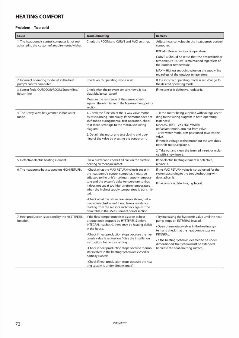
8/3/2019 Dhp Install Vmbma202 En
http://slidepdf.com/reader/full/dhp-install-vmbma202-en 72/96
72 VMBMA202
HEATING COMFORT
Problem – Too cold
Cause Troubleshooting Remedy
1. The heat pump’s control computer is not set/
adjusted to the customer’s requirements/wishes.
Check the ROOM and CURVE and MAX settings. Adjust incorrect values in the heat pump’s control
computer.
ROOM = Desired indoor temperature
CURVE = Should be set so that the desired indoor
temperature (ROOM) is maintained regardless of
the outdoor temperature.
MAX = Highest set-point value on the supply line
regardless of the outdoor temperature.
2. Incorrect operating mode set in the heat
pump’s control computer.
Check which operating mode is set. If the incorrect operating mode is set, change to
the desired operating mode.
3. Sensor fault, OUTDOOR/ROOM/Supply line/
Return line.
Check what the relevant sensor shows, is it a
plausible/actual value?
Measure the resistance of the sensor, check
against the ohm table in the Measurement points
section.
If the sensor is defective, replace it.
4. The 3-way valve has jammed in hot water
mode.
1. Check the function of the 3-way valve motor
by test running it manually. If the motor does notshift mode during manual test operation, check
that there is voltage to the motor, see wiring
diagram.
2. Detach the motor and test closing and ope-
ning of the valve by pressing the control arm.
1. Is the motor being supplied with voltage accor-
ding to the wiring diagram in both operatinginstances?
MANUAL TEST – VXV HOT WATER
0=Radiator mode, arm out from valve.
1=Hot water mode, arm positioned towards the
valve.
If there is voltage to the motor but the arm does
not shift mode, replace it.
2. Take out and clean the jammed insert, or repla-
ce with a new insert.
5. Defective electric heating element. Use a buzzer and check if all coils in the electric
heating element are intact.
If the electric heating element is defective,
replace it.
6. The heat pump has stopped on HIGH RETURN. • Check what the MAX RETURN value is set at in
the heat pump’s control computer. It must be
adjusted to the unit’s maximum supply tempera-ture and the system’s delta temperature so that
it does not cut at too high a return temperature
when the highest supply temperature is transmit-
ted.
• Check what the return line sensor shows, is it a
plausible/actual value? If not, take a resistance
reading from the sensors and check against the
ohm table in the Measurement points section.
If the MAX RETURN value is not adjusted for the
system according to the troubleshooting win-
dow, adjust it.
If the sensor is defective, replace it.
7. Heat production is stopped by the HYSTERESIS
function.
If the flow temperature rises as soon as heat
production is stopped by HYSTERESIS before
INTEGRAL reaches 0, there may be heating deficit
in the house.
• Check if heat production stops because the hys-
teresis value is set too low? (See the installation
instructions for factory setting.)
• Check if heat production stops because thermo-
stats/valves in the heating system are closed or
partially closed?
• Check if heat production stops because the hea-
ting system is under dimensioned?
• Try increasing the hysteresis value until the heat
pump stops on INTEGRAL instead.
• Open thermostats/valves in the heating sys-
tem and check that the heat pump stops on
INTEGRAL.
• If the heating system is deemed to be under
dimensioned, the system must be extended
(increase the heat emitting surface).

8/3/2019 Dhp Install Vmbma202 En
http://slidepdf.com/reader/full/dhp-install-vmbma202-en 73/96
73VMBMA202
Cause Troubleshooting Remedy
8. The auxiliary heater is not permitted to cut in
with sufficient output.
Value set too low on MAXSTEP.
MAXSTEP 1 = 3 kW
MAXSTEP 2 = 6 kW
MAXSTEP 3 = 9 kW
MAXSTEP 4 = 12 kW (only DHP-A, -AL)
MAXSTEP 5 = 15 kW (only DHP-A, -AL)
MAXSTEP +4 = 12 kW (only DHP-A, -AL)
MAXSTEP +5 = 15 kW (only DHP-A, -AL)
Check the set value on MAXSTEP in the heat
pump’s control computer.
If necessary, adjust the MAXSTEP value in the
heat pump’s control computer.
MAXSTEP 1 = 3 kW
MAXSTEP 2 = 6 kW
MAXSTEP 3 = 9 kW
MAXSTEP 4 = 12 kW (only DHP-A, -AL, cannot cut
in when the compressor is running.)
MAXSTEP 5 = 15 kW (only DHP-A, -AL, cannot cutin when the compressor is running.)
MAXSTEP +4 = 12 kW (only DHP-A, -AL, can cut in
when the compressor is running.)
MAXSTEP +5 = 15 kW (only DHP-A, -AL, can cut in
when the compressor is running.)
9. The external auxiliary heater does not start
when the heat pump’s control computer requests
it.
If an external auxiliary heater is used, check
that it is correctly installed by test running it in
MANUAL TEST – ADD.HEAT - 1.
If it does not start at manual test operation, check
that the start signal/voltage comes from the heat
pump. See wiring diagram.
Connect the external auxiliary heater according
to the instructions.
Measure the voltage on the control computer’s
probe L2 Oil/Electricity.
10. Closed or partially closed thermostats/valves
in the heating system.
Check that the thermostats/valves in the heating
system are open.
Open closed thermostats/valves.
11. The total output of the heat pump and auxi-
liary heater is too low in relation to the building’s
power demand.
What is the building’s power demand?
What is the output of the heat pump?
What is the output of the auxiliary heater, what
is it set to?
Ensure that available power is at least as great as
the building’s power demand.
12. Under dimensioned heating system. Check existing heating system.
What output is it dimensioned for to produce at
what supply temperature?
What output is required to keep the room warm?
If the heating system is dimensioned for greater
supply temperatures than the heat pump can
provide, it must be adjusted by increasing the
heat emitting surface for example.
If the room requires a higher output than the
heating system can provide, extend the heating
system.
13. Changed conditions.
Have you increased your heating and/or hot
water demand?
• If the heat pump has been dimensioned for acertain demand and this demand is increased,
the heat pump might not be able to maintain the
desired room temperature.
• If hot water consumption increases, a larger
proportion of time is used to produce hot water,
which means less time for heat production (only
applies to VL-systems).
If the heat pump cannot cope with the demand,replace it with one with a higher output or supp-
lement it with a higher output auxiliary heater.
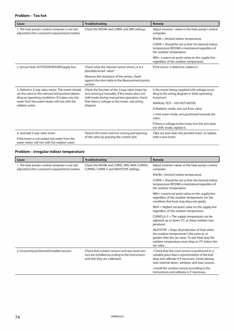
8/3/2019 Dhp Install Vmbma202 En
http://slidepdf.com/reader/full/dhp-install-vmbma202-en 74/96
74 VMBMA202
Problem – Too hot
Cause Troubleshooting Remedy
1. The heat pump’s control computer is not set/
adjusted to the customer’s requirements/wishes.
Check the ROOM and CURVE and MIN settings. Adjust incorrect values in the heat pump’s control
computer.
ROOM = Desired indoor temperature.
CURVE = Should be set so that the desired indoor
temperature (ROOM) is maintained regardless of
the outdoor temperature.
MIN = Lowest set-point value on the supply lineregardless of the outdoor temperature.
2. Sensor fault, OUTDOOR/ROOM/Supply line. Check what the relevant sensor shows, is it a
plausible/actual value?
Measure the resistance of the sensor, check
against the ohm table in the Measurement points
section.
If the sensor is defective, replace it.
3. Defective 3-way valve motor. The motor should
set the valve to the relevant end position depen-
ding on operating conditions. If it does not, hot
water from the water heater will mix with the
radiator water.
Check the function of the 3-way valve motor by
test running it manually. If the motor does not
shift mode during manual test operation, check
that there is voltage to the motor, see wiring
diagram.
Is the motor being supplied with voltage accor-
ding to the wiring diagram in both operating
instances?
MANUAL TEST – VXV HOT WATER
0=Radiator mode, arm out from valve.
1=Hot water mode, arm positioned towards the
valve.
If there is voltage to the motor but the arm does
not shift mode, replace it.
4. Jammed 3-way valve insert.
If the insert is not sealed, hot water from the
water heater will mix with the radiator water.
Detach the motor and test closing and opening
of the valve by pressing the control arm.
Take out and clean the jammed insert, or replace
with a new insert.
Problem – irregular indoor temperature
Cause Troubleshooting Remedy
1. The heat pump’s control computer is not set/
adjusted to the customer’s requirements/wishes.
Check the ROOM and CURVE, MIN, MAX CURVE5,
CURVE0, CURVE-5 and HEATSTOP settings.
Adjust incorrect values in the heat pump’s control
computer.
ROOM = Desired indoor temperature
CURVE = Should be set so that the desired indoor
temperature (ROOM) is maintained regardless of
the outdoor temperature.
MIN = Lowest set-point value on the supply line
regardless of the outdoor temperature (on the
condition that heat-stop does not apply).
MAX = Highest set-point value on the supply line
regardless of the outdoor temperature.
CURVE5,0,-5 = The supply temperature can be
adjusted up or down 5°C at these outdoor tem-
peratures.
HEATSTOP = Stops all production of heat when
the outdoor temperature is the same as or
greater than the set value. To exit heat-stop the
outdoor temperature must drop to 3°C below the
set value.
2. Incorrectly positioned/installed sensors. Check that outdoor sensors and any room sen-
sors are installed according to the instructions
and that they are calibrated.
• Check that the room sensor is positioned in a
suitable place that is representative of the buil-
ding and calibrate it if necessary. Avoid placing
near external doors, windows and heat sources.
• Install the outdoor sensor according to the
instructions and calibrate it, if necessary.

8/3/2019 Dhp Install Vmbma202 En
http://slidepdf.com/reader/full/dhp-install-vmbma202-en 75/96
75VMBMA202
OTHER
Problem – The heat pump runs and runs but never stops
Cause Troubleshooting Remedy
1. Air in the heating system. Listen for air in the heat pump and heating sys-
tem.
Bleed the heating system circuit according to the
installation instructions.
2. Lack of refrigerant, not enough refrigerant in
the system.
Using manometer apparatus and thermometer,
check that the unit’s overheating is correct for the
specific refrigerant.
Follow the correct procedure (depending on
type of refrigerant) to add the correct amount of
refrigerant.
If there appears to be a leak in the refrigerant
circuit, carry out leak tracing and any necessary
corrective action. If leak tracer is not available,
brush soap water on the suspected leak and look
for bubbles. Also check for oil as this can come
out from the refrigerant circuit.
3. Changed conditions. Have you increased your
heating and/or hot water demand?
• If the heat pump has been dimensioned for a
certain demand and this demand is increased,
the heat pump might not be able to maintain the
desired room temperature.
• If hot water consumption increases, a larger
proportion of time is used to produce hot water,
which means less time for heat production (only
applies to VL-systems).
If the heat pump cannot cope with the demand,
replace it with one with a higher output or supp-
lement it with a higher output auxiliary heater.
Problem – Runs on electric heating element
Cause Troubleshooting Remedy
1. Operating mode ADD.HEAT is selected. If this operating mode is selected, the auxiliary
heater is used for heating and hot water produc-
tion, not the compressor.
If ADD.HEAT mode is selected and you no longer
want it, change to AUTO, the heat pump then
controls both the compressor and auxiliary hea-
ter.
2. The compressor cannot run due to an alarm. Check the alarm that is indicated in the display. Rectify the problem and rest the alarm. See the
Operational problem – Alarm, section.
3. The integral value has reached the start level
for the auxiliary heater.
Check what the integral value is in the control
computer.
If the auxiliary heater is in operation because
the integral value has counted down to the start
value, the computer reacts as it should, see theHeat pump for further information.
4. Peak heat operation (legionella function) is
running.
Check if the heat pump runs peak heat. See the
instructions for the relevant model.
Peak heat operation occurs in connection with
hot water production with the set interval. The
compressor should then start to produce hot
water and 2 minutes later the auxiliary heater
starts, the compressor should then stop and the
stop temperature is reached with only the auxi-
liary heater connected. Take no corrective action.
5. The heat pump has stopped on HIGH RETURN. • Check what the MAX RETURN value is set at in
the heat pump’s control computer. It must be
adjusted to the unit’s maximum supply tempera-
ture and the system’s delta temperature so that
it does not cut at too high a return temperature
when the highest supply temperature is transmit-ted.
• Check what the return line sensor shows, is it a
plausible/actual value? If not, take a resistance
reading from the sensors and check against the
ohm table in the Measurement points section.
If the MAX RETURN value is not adjusted for the
system according to the troubleshooting win-
dow, adjust it.
If the sensor is defective, replace it.

8/3/2019 Dhp Install Vmbma202 En
http://slidepdf.com/reader/full/dhp-install-vmbma202-en 76/96
76 VMBMA202
Cause Troubleshooting Remedy
6. The compressor runs backwards. The incoming
phases have the incorrect sequence (only applies
to 3-phase heat pumps).
If the compressor runs backwards, it will not cope
with compressing the refrigerant and therefore
does not produce the correct power, which leads
to the control computer requesting auxiliary
heating.
• If the text ERR PHASE SEQ appears in the display
when the heat pump is powered, (only appears in
the first 10 minutes) this means that the phases
have the incorrect sequence.
• When the compressor is running, check the
delivery pipe temperature by feeling the delivery
pipe that should be hot (not just warm) even a
little distance from the compressor if the phases
are correctly sequenced.
• When the compressor runs with the phases
incorrectly sequenced a strange noise may be
heard (loud, rattling) when the compressor runs
backwards.
If the phases are in the incorrect order, switch
two incoming phases at the main terminal block
and recheck according to the troubleshooting
window.
7. Changed conditions. Have you increased your
heating and/or hot water demand?
• If the heat pump has been dimensioned for a
certain demand and this demand is increased,
the heat pump might not be able to maintain the
desired room temperature.
• If hot water consumption increases, a larger
proportion of time is used to produce hot water,
which means less time for heat production (only
applies to VL-systems).
If the heat pump cannot cope with the demand,
replace it with one with a higher output or supp-
lement it with a higher output auxiliary heater.
Problem – The auxiliary heater is in operation but not the compressor
Cause Troubleshooting Remedy
1. Operating mode ADD.HEAT is selected. If this operating mode is selected, the auxiliary
heater is used for heating and hot water produc-
tion, not the compressor.
If ADD.HEAT mode is selected and you no longer
want it, change to AUTO, the heat pump then
controls both the compressor and auxiliary hea-
ter.
2. Peak heat operation (legionella function) is
running.
Check if the heat pump runs peak heat. See the
instructions for the relevant model.
Peak heat operation occurs in connection with
hot water production with the set interval. The
compressor should then start to produce hot
water and 2 minutes later the auxiliary heater
starts, the compressor should then stop and the
stop temperature is reached with only the auxi-
liary heater connected. Take no corrective action,
this is normal.
3. The compressor cannot run due to an alarm. Check the alarm that is indicated in the display. Rectify the problem and rest the alarm. See the
Operational problem – Alarm, section.
4. The heat pump has stopped on high return. • Check what the MAX value is set at in the heat
pump’s control computer. It must be adjusted to
the unit’s maximum supply temperature and the
system’s delta temperature so that it does not cut
at too high a return temperature when the hig-
hest supply temperature is transmitted.
• Check what the return line sensor shows, is it a
plausible/actual value? If not, take a resistance
reading from the sensors and check against the
ohm table in the Measurement points section.
• If the MAX RETURN value is not adjusted for the
system according to the troubleshooting win-
dow, adjust it.
• If the sensor is defective, replace it.
5. The compressor has been stopped by the ope-rating pressure switch or delivery pipe sensor.
Check if a square appears in the display’s lowerlet corner, if so, the operating pressure switch
is open or the delivery pipe sensor triggers an
alarm for too high temperature.
• The operating pressure switch is most easily
checked by using a buzzer to see if it is connec-
ted.
• The delivery pipe sensor value is read off from
the control computer in the HEATPUMP menu. Is
it a plausible/actual value? If not, take a resistan-
ce reading from the sensor and check against the
ohm table in the Measurement points section.
• The compressor has been stopped by the deli-
very pipe sensor and you have established that
it shows the correct temperature. This may havebeen caused by a leak in the refrigerant circuit.
If the operating pressure switch has stuck in theopen position, try gently tapping on the pressure
switch head. If this does not help, or it sticks in
the open position repeatedly, replace the pres-
sure switch.
If the delivery pipe sensor is defective, replace it.
If the delivery pipe temperature gets so hot that
the compressor stops, start by leak-tracing the
unit. Rectify the leak, if a leak is found. If no leak
is found, try draining and refilling the unit and
then restarting the heat pump and seeing what
the delivery pipe temperature is. If the problem
persists, replace the compressor.

8/3/2019 Dhp Install Vmbma202 En
http://slidepdf.com/reader/full/dhp-install-vmbma202-en 77/96
77VMBMA202
Cause Troubleshooting Remedy
6. The built-in overheating protection (bi-metal
protection) in the compressor has tripped.
Check if the heat pump’s control computer indi-
cates that the compressor is in operation, and if
there is voltage between soft-starters A1 and A2.
Then read off and check that there is voltage on
the compressor’s three electrical connections (L1,
L2 and L3).
If there is voltage on the compressor’s three
electrical connections and the overheating pro-
tection does not close when the compressor has
not run and has cooled down for at least 1 hour,
replace the compressor.
7. The compressor runs backwards. The incoming
phases have the incorrect sequence (only applies
to 3-phase heat pumps). If the compressor runs
backwards, it will not cope with compressing the
refrigerant and therefore does not produce the
correct power, which leads to the control compu-
ter requesting auxiliary heating.
• If the text ERR PHASE SEQ appears in the display
when the heat pump is powered, (only appears in
the first 10 minutes) this means that the phases
have the incorrect sequence.
• When the compressor is running, check the
delivery pipe temperature by feeling the delivery
pipe that should be hot (not just warm) even a
little distance from the compressor if the phases
are correctly sequenced.
• When the compressor runs with the phases
incorrectly sequenced a strange noise may be
heard (loud, rattling) when the compressor runs
backwards.
If the phases are in the incorrect order, switch
two incoming phases at the main terminal block
and recheck according to the troubleshooting
window.
Problem – The heat pump consumes too much energy
Cause Troubleshooting Remedy1. Blocked strainer in the heating system. Check that the strainer is not blocked. Clean the strainer if necessary.
2. The compressor cannot run due to an alarm. Check the alarm that is indicated in the display. Rectify the problem and rest the alarm. See the
Operational problem – Alarm, section.
3. Incorrect flow over hot side of the heat pump. Measurement check what the difference between
the supply and return line is using a thermometer
(∆t). The difference should be about 7-10°C (can
vary depending on refrigerant). A lower ∆t results
in reduced efficiency in the heat pump.
Adjust the system to obtain the correct ∆t.
4. Incorrect flow in the brine circuit. Measurement check what the difference between
the supply and return line is using a thermometer
(∆t). The difference should not be more than 4°C.
A greater ∆t results in reduced efficiency in the
heat pump.
If the difference is greater than 4°C note what is
causing it. E.G.: Dirt in the filter, system restric-
tions, system with high pressure drop.
5. The heat pump’s control computer is not set/
adjusted to the customer’s requirements/wishes.
Check the ROOM and CURVE and MIN settings. Adjust incorrect values in the heat pump’s control
computer.
ROOM = Desired indoor temperature.
CURVE = Should be set so that the desired indoor
temperature (ROOM) is maintained regardless of
the outdoor temperature.
MIN = Lowest set-point value on the supply line
regardless of the outdoor temperature.
6. The interval for peak heat operation has chan-
ged to a lower value than the factory set value.
This results in the heat pump going into peak
heat operation more often than calculated.
Check the specified interval for peak heat opera-
tion in the control computer, see instructions for
relevant model.
If there is a shorter interval between the peak
heat productions, this explains why the unit
consumes more current than calculated, but
this does not mean for sure that it should be
increased, there might be a reason why the inter-val has been changed.
7. The heat pump has stopped on HIGH RETURN. • Check what the MAX RETURN value is set at in
the heat pump’s control computer. It must be
adjusted to the unit’s maximum supply tempera-
ture and the system’s delta temperature so that
it does not cut at too high a return temperature
when the highest supply temperature is transmit-
ted.
• Check what the return line sensor shows, is it a
plausible/actual value? If not, take a resistance
reading from the sensors and check against the
ohm table in the Measurement points section.
If the MAX RETURN value is not adjusted for the
system according to the troubleshooting win-
dow, adjust it.
If the sensor is defective, replace it.

8/3/2019 Dhp Install Vmbma202 En
http://slidepdf.com/reader/full/dhp-install-vmbma202-en 78/96
78 VMBMA202
Cause Troubleshooting Remedy
8. The compressor runs backwards. The incoming
phases have the incorrect sequence (only applies
to 3-phase heat pumps). If the compressor runs
backwards, it will not cope with compressing the
refrigerant and therefore does not produce the
correct power, which leads to the control compu-
ter requesting auxiliary heating.
• If the text ERR PHASE SEQ appears in the display
when the heat pump is powered, (only appears in
the first 10 minutes) this means that the phases
have the incorrect sequence.
• When the compressor is running, check the
delivery pipe temperature by feeling the delivery
pipe that should be hot (not just warm) even a
little distance from the compressor if the phases
are correctly sequenced.
• When the compressor runs with the phases
incorrectly sequenced a strange noise may be
heard (loud, rattling) when the compressor runs
backwards.
If the phases are in the incorrect order, switch
two incoming phases at the main terminal block
and recheck according to the troubleshooting
window.
9. The compressor has been stopped by the ope-
rating pressure switch or delivery pipe sensor.
Check if a square appears in the display’s lower
let corner, if so, the operating pressure switch
is open or the delivery pipe sensor triggers an
alarm for too high temperature.
• The operating pressure switch is most easily
checked by using a buzzer to see if it is connec-
ted.
• The delivery pipe sensor value is read off from
the control computer in the HEATPUMP menu.
Is it a plausible/actual value? If not, take a resis-tance reading from the sensor and check against
the ohm table in the installation instructions.
• The compressor has been stopped by the deli-
very pipe sensor and you have established that
it shows the correct temperature. This may have
been caused by a leak in the refrigerant circuit.
If the operating pressure switch has stuck in the
open position, try gently tapping on the pressure
switch head. If this does not help, or it sticks in
the open position repeatedly, replace the pres-
sure switch.
If the delivery pipe sensor is defective, replace it.
If the delivery pipe temperature gets so hot that
the compressor stops, start by leak-tracing the
unit. Rectify the leak, if a leak is found. If no leak
is found, try draining and refilling the unit andthen restarting the heat pump and seeing what
the delivery pipe temperature is. If the problem
persists, replace the compressor.
10. Expansion valve defective or incorrectly set. Using manometer apparatus and thermometer
check what the overheating reading of the unit is.
Also check that bulb and capillary tube are unda-
maged and that the bulb is correctly installed.
If the overheating reading does not correspond
with the instructions for the specific refrigerant,
adjust the expansion valve until the correct value
is obtained. See separate instructions for cooling
techniques.
If overheating cannot be adjusted with the
expansion valve or if the capillary tube/bulb is
damaged, replace it.
11. Lack of refrigerant, not enough refrigerant in
the system.
Using manometer apparatus and thermometer,
check that the unit’s overheating is correct for the
specific refrigerant.
Follow the correct procedure (depending on
type of refrigerant) to add the correct amount of
refrigerant.
If there appears to be a leak in the refrigerant
circuit, carry out leak tracing and any necessary
corrective action. If leak tracer is not available,
brush soap water on the suspected leak and look
for bubbles. Also check for oil as this can come
out from the refrigerant circuit.
12. Overfilled refrigerant circuit. Using manometer apparatus and thermometer,
check that the unit’s overheating is correct for the
specific refrigerant.
If cooling is not at the correct level compared
with the specific refrigerant and is too high, there
is too much refrigerant in the unit. Follow the cor-
rect procedure (depending on type of refrigerant)to add the correct amount of refrigerant.
13. Short active collector, e.g. short or dry bore
hole, short surface soil collector.
• Check the length of the collector that is being
used and compare with the collector length in
the dimensioning documentation.
• In addition, check that the collector is not sus-
pended ”in free air” if boreholes are used.
If the active collector is too short, the heat pump
cannot receive enough energy from the heat
source , which results in it requiring an addition
to cover the energy requirement.
14. Changed conditions. Have you increased your
heating and/or hot water demand?
• If the heat pump has been dimensioned for a
certain demand and this demand is increased,
the heat pump might not be able to maintain the
desired room temperature.
• If hot water consumption increases, a larger
proportion of time is used to produce hot water,
which means less time for heat production (onlyapplies to VL-systems).
If the heat pump cannot cope with the demand,
replace it with one with a higher output or supp-
lement it with a higher output auxiliary heater.

8/3/2019 Dhp Install Vmbma202 En
http://slidepdf.com/reader/full/dhp-install-vmbma202-en 79/96
79VMBMA202
Problem – Auxiliary heater cuts in too soon
Cause Troubleshooting Remedy
1. The heat pump’s control computer is not set/
adjusted to the customer’s requirements/wishes.
Check the ROOM, CURVE, INTEGRAL A1 and
INTEGRAL A2 settings
Adjust incorrect values in the heat pump’s control
computer.
ROOM = Desired indoor temperature.
CURVE = Should be set so that the desired indoor
temperature (ROOM) is maintained regardless of
the outdoor temperature.
INTEGRAL A1 = Start value for the compressor.
INTEGRAL A2 = Start value (calculated from A1)
for the auxiliary heater.
2. Lack of refrigerant, not enough refrigerant in
the system.
Using manometer apparatus and thermometer,
check that the unit’s overheating is correct for the
specific refrigerant.
Follow the correct procedure (depending on
type of refrigerant) to add the correct amount of
refrigerant.
If there appears to be a leak in the refrigerant
circuit, carry out leak tracing and any necessary
corrective action. If leak tracer is not available,
brush soap water on the suspected leak and look
for bubbles. Also check for oil as this can come
out from the refrigerant circuit.
3. Short active collector, e.g. short or dry bore
hole, short surface soil collector.
• Check the length of the collector that is being
used and compare with the collector length inthe dimensioning documentation.
• In addition, check that the collector is not sus-
pended ”in free air” if boreholes are used.
If the active collector is too short, the heat pump
cannot receive enough energy from the heatsource , which results in it requiring an addition
to cover the energy requirement.
4. Collector too long, pressure drop too great. Check the length of the collector that is being
used and that it is connected in parallel (not con-
nected in series) if more than 1 coil is being used.
If a longer collector is being used than recom-
mended for the specific heat pump, it must be
divided on several parallel connected coils.
5. Changed conditions. Have you increased your
heating and/or hot water demand?
• If the heat pump has been dimensioned for a
certain demand and this demand is increased,
the heat pump might not be able to maintain the
desired room temperature.
• If hot water consumption increases, a larger
proportion of time is used to produce hot water,
which means less time for heat production (only
applies to VL-systems).
If the heat pump cannot cope with the demand,
replace it with one with a higher output or supp-
lement it with a higher output auxiliary heater.
Problem – Short operating times despite heating demand
Cause Troubleshooting Remedy
ROOM and/or CURVE set too high in combination
with a heating system with poor circulation due
to closed radiator valves, too small elements or
insufficient water volume. A tight fitting system
with poor pipe dimensions may produce the
same phenomena.
Check if the heat pumps starts, if the supply tem-
perature rises quickly whilst nothing happens to
the return temperature.
If this happens and the heat pump is stopped by
the hysteresis function to later drop in tempera-
ture (supply) as quickly to start again, but cannot
due to time conditions in regulation, this means
that the heat pump cannot transport the heataway from the condenser as it should.
In such a case, hysteresis starts and stops the
heat pump often.
Adjust ROOM and CURVE if necessary, ensure that
there is sufficient flow over the condenser and
the heating circuit.
Problem – Connection of external AH
Cause Troubleshooting Remedy
Incorrectly connected auxiliary heater. Does not
start when the control computer gives the signal.
Check the connection against the instructions/
wiring diagram. Test the function in manual
mode.
If the auxiliary heater is incorrectly connected,
reconnect according to the instructions.

8/3/2019 Dhp Install Vmbma202 En
http://slidepdf.com/reader/full/dhp-install-vmbma202-en 80/96

8/3/2019 Dhp Install Vmbma202 En
http://slidepdf.com/reader/full/dhp-install-vmbma202-en 81/96
81VMBMA202
OUTDOOR UNIT
Problem – Noise/loud noise
Cause Troubleshooting Remedy
1. Positioning the outdoor unit. Determine whether the outdoor unit can be
moved to a more suitable location.
When positioning the outdoor unit, its direction
does not affect its performance. The outdoor
unit does not need to be positioned as close to
the heat pump as necessary, it can be positioned
as far as 30 ”pipe metres” way.2. Connection/wall lead-ins. Check that the unit is installed according to the
instructions.
Is the outdoor unit secured to the wall?
Rigid mountings can generate noise from the
outdoor section via walls in the house.
Problem – Defrosting problems
Cause Troubleshooting Remedy
1. Location/calibration of the outdoor sensor. Check that the outdoor sensor is installed accor-
ding to the installation instructions and that it is
correctly calibrated.
Install according to the instructions and calibrate,
if necessary. Alternatively, the outdoor sensor can
be located behind the outdoor unit 20 cm out
from the rear side of the outdoor unit.
2. Brine temperature in/out. Measurement check the temperatures with athermometer.
If necessary, calibrate BRINE IN and BRINE OUT inthe heat pump’s control computer.
3. The defroster shunt does not regulate as it
should.
Manually test to check if the defroster shunt
opens and closes the flow over the defroster
tank.
If the motor switches position when testing, but
defrosting still does not function, remove the
motor and try closing and opening the valve by
hand by pressing in the control arm.
If the motor is defective, replace it.
If the insert jams, remove and clean/lubricate it,
or replace it.
Problem – Build-up of ice under and around the outdoor unit
Cause Troubleshooting RemedyInsufficient drainage. Does a lot of ice accumulate under and around
the outdoor unit because the melted water has
no where to run?
Drain the ground under and around the outdoor
section
or
Install a drip tray with a drainpipe routed to an
indoor drain or gully. NOTE! A heating cable may
have to be installed in the drainpipe.
Problem – Water run-off by the outdoor unit, risk of moisture problems in house foundations
Cause Troubleshooting Remedy
Insufficient drainage. During some periods when the outdoor unit is
being defrosted, large amounts (20-40 L/day) of water can run off.
Drain the ground under and around the outdoor
unit so that it can cope with the extra amount of water produced because of defrosting
or
Install a drip tray with a drainpipe routed to an
indoor drain or gully. NOTE! A heating cable may
have to be installed in the drainpipe.

8/3/2019 Dhp Install Vmbma202 En
http://slidepdf.com/reader/full/dhp-install-vmbma202-en 82/96
82 VMBMA202
17 Technical data
Heat pump DHP-H Refrigerant Type
Amount kg
Test pressure MPaDesign pressure MPa
Compressor Type Scroll Scroll Scroll Scroll Scroll ScrollOil POE POE POE POE POE POE
Electrical data 3-N Main supply VoltRated power, compressor kWAuxiliary heater, max3 steps
kW
Start current ACircuit breaker A
Electrical data 1-N Main supply VoltRated power, compressor kWAuxiliary heater, max3 steps
kW
Start current ACircuit breaker A
Performance 1) Output capacity kWHeat factor COP
Nominal flow 6) Cooling circuit l/sHeating circuit l/s
External availablepressure 5) Cooling circuit kPa
Heating circuit kPa
Max/min temperature Cooling circuit oCHeating circuit oC
Pressure switches Low pressure MPaOperating MPaHigh pressure MPa
Anti freeze media Ethylene glycol/Ethanol
Ethylene glycol/Ethanol
Ethylene glycol/Ethanol
Ethylene glycol/Ethanol
Ethylene glycol/Ethanol
Ethylene glycol/Ethanol
Water heater volume l
Weight kg
4 6 8 10 12 16R407C R407C R407C R407C R407C R407C
0.75 1.20 1.30 1.45 1.55 2.10
3.2 3.2 3.2 3.2 3.2 3.23.1 3.1 3.1 3.1 3.1 3.1
400/50Hz 400/50Hz 400/50Hz 400/50Hz 400/50Hz 400/50Hz2.7 2.0 2.3 3.6 4.4 5.6
3/6/9 3/6/9 3/6/9 3/6/9 3/6/9 3/6/9
36 14 25 29 32 45102) /103) /164) 102) /163) /204) 162) /163) /204) 162) /163) /204) 162) /203) /254) 202) /203) /254)
230/50Hz 230/50Hz 230/50Hz 230/50Hz 230/50Hz *)
2.7 3.3 4.2 5.4 5.7 *)
1.5/3/4.5 1.5/3/4.5 1.5/3/4.5 1.5/3/4.5 1.5/3/4.5 *)
36 58 56 97 108 *)
202) /253) /324) 252) /323) /404) 252) /323) /404) 322) /403) /504) 322) /403) /504) *)
3.2 4.9 7.2 8.9 10.7 15.22.6 2.8 3.1 3.2 3.1 3.2
0.2 0.3 0.5 0.6 0.6 0.90.1 0.1 0.2 0.2 0.3 0.4
31 31 33 32 64 5647 44 42 39 51 57
20/-10 20/-10 20/-10 20/-10 20/10 20/-1055/20 55/20 55/20 55/20 55/20 55/20
0.08 0.08 0.08 0.08 0.08 0.082.65/2.85 2.65/2.85 2.65/2.85 2.65/2.85 2.65/2.85 2.65/2.85
3.10 3.10 3.10 3.10 3.10 3.10
180 180 180 180 180 180
229 229 229 229 238 242
1) At B0W45 according to EN 14511 (including circulation pumps).2) Heat pump with 3 kW auxiliary heater (1-N 1.5 kW).3)
Heat pump with 6 kW auxiliary heater (1-N 3 kW).4) Heat pump with 9 kW auxiliary heater (1-N 4.5 kW).5) Pressure drop that must not be exceeded outside the heat pump without the nominal flow being reduced.
For the cooling circuit these values require a pipe of Ø 40x2.4.6) Nominal flow: heating circuit Δ10K, cooling circuit Δ3K.* ) Not available in 230V 1-N version.
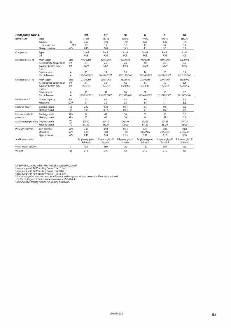
8/3/2019 Dhp Install Vmbma202 En
http://slidepdf.com/reader/full/dhp-install-vmbma202-en 83/96
83VMBMA202
Heat pump DHP-C Refrigerant Type
Amount kg
Test pressure MPaDesign pressure MPa
Compressor Type Scroll Scroll Scroll Scroll Scroll ScrollOil POE POE POE POE POE POE
Electrical data 3-N Main supply VoltRated power, compressor kWAuxiliary heater, max3 steps
kW
Start current ACircuit breaker A
Electrical data 1-N Main supply VoltRated power, compressor kWAuxiliary heater, max3 steps
kW
Start current ACircuit breaker A
Performance 1) Output capacity kWHeat factor COP
Nominal flow 6) Cooling circuit l/sHeating circuit l/s
External availablepressure 5) Cooling circuit kPa
Heating circuit kPa
Max/min temperature Cooling circuit oCHeating circuit oC
Pressure switches Low pressure MPaOperating MPaHigh pressure MPa
Anti freeze media Ethylene glycol/Ethanol
Ethylene glycol/Ethanol
Ethylene glycol/Ethanol
Ethylene glycol/Ethanol
Ethylene glycol/Ethanol
Ethylene glycol/Ethanol
Water heater volume l
Weight kg
4H 5H 7H 6 8 10R134a R134a R134a R407C R407C R407C0.90 1.00 1.10 1.20 1.30 1.45
3.2 3.2 3.2 3.2 3.2 3.22.45 2.45 2.45 3.1 3.1 3.1
400/50Hz 400/50Hz 400/50Hz 400/50Hz 400/50Hz 400/50Hz2.7 2.0 2.3 2.0 2.3 3.6
3/6/9 3/6/9 3/6/9 3/6/9 3/6/9 3/6/9
36 14 29 14 25 29102) /103) /164) 102) /163) /204) 102) /163) /204) 102) /163) /204) 162) /163) /204) 162) /163) /204)
230/50Hz 230/50Hz 230/50Hz 230/50Hz 230/50Hz 230/50Hz
2.7 3.3 4.2 3.3 4.2 5.41.5/3/4.5 1.5/3/4.5 1.5/3/4.5 1.5/3/4.5 1.5/3/4.5 1.5/3/4.5
36 58 76 58 56 97202) /253) /324) 252) /323) /404) 252) /323) /404) 322) /403) /504) 322) /403) /504) 322) /403) /504)
3.2 4.5 5.5 4.9 7.2 8.92.7 2.9 2.9 2.8 3.1 3.2
0.20 0.28 0.37 0.3 0.5 0.60.08 0.12 0.14 0.1 0.2 0.2
34 48 54 31 33 3261 60 58 44 42 39
20/-10 20/-10 20/-10 20/-25 20/-25 20/-2555/20 55/20 55/20 55/20 55/20 55/20
0.03 0.03 0.03 0.08 0.08 0.081.80 1.80 1.80 2.65/2.85 2.65/2.85 2.65/2.852.45 2.45 2.45 3.10 3.10 3.10
180 180 180 180 180 180
210 215 225 210 215 225
1) At B0W45 according to EN 14511 (including circulation pumps).2) Heat pump with 3 kW auxiliary heater (1-N 1.5 kW).3)
Heat pump with 6 kW auxiliary heater (1-N 3 kW).4) Heat pump with 9 kW auxiliary heater (1-N 4.5 kW).5) Pressure drop that must not be exceeded outside the heat pump without the nominal flow being reduced.
For the cooling circuit these values require a pipe of Ø 40x2.4.6) Nominal flow: heating circuit Δ10K, cooling circuit Δ3K.

8/3/2019 Dhp Install Vmbma202 En
http://slidepdf.com/reader/full/dhp-install-vmbma202-en 84/96
84 VMBMA202
Heat pump DHP-LRefrigerant Type
Amount kg
Test pressure MPaDesign pressure MPa
Compressor Type Scroll Scroll Scroll Scroll Scroll ScrollOil POE POE POE POE POE POE
Electrical data 3-N Main supply VoltRated power, compressor kWAuxiliary heater, max3 steps
kW
Start current ACircuit breaker A
Electrical data 1-N Main supply VoltRated power, compressor kWAuxiliary heater, max3 steps
kW
Start current ACircuit breaker A
Performance 1) Output capacity kWHeat factor COP
Nominal flow 6) Cooling circuit l/sHeating circuit l/s
External availablepressure 5) Cooling circuit kPa
Heating circuit kPa
Max/min temperature Cooling circuit oCHeating circuit oC
Pressure switches Low pressure MPaOperating MPaHigh pressure MPa
Anti freeze media Ethylene glycol/Ethanol
Ethylene glycol/Ethanol
Ethylene glycol/Ethanol
Ethylene glycol/Ethanol
Ethylene glycol/Ethanol
Ethylene glycol/Ethanol
Weight kg
4 6 8 10 12 16R407C R407C R407C R407C R407C R407C
0.75 1.20 1.30 1.45 1.55 2.10
3.2 3.2 3.2 3.2 3.2 3.23.1 3.1 3.1 3.1 3.1 3.1
400/50Hz 400/50Hz 400/50Hz 400/50Hz 400/50Hz 400/50Hz2.7 2.0 2.3 3.6 4.4 5.6
3/6/9 3/6/9 3/6/9 3/6/9 3/6/9 3/6/9
36 14 25 29 32 45102) /103) /164) 102) /163) /204) 162) /163) /204) 162) /163) /204) 162) /203) /254) 202) /203) /254)
230/50Hz 230/50Hz 230/50Hz 230/50Hz 230/50Hz *)
2.7 3.3 4.2 5.4 5.7 *)
1.5/3/4.5 1.5/3/4.5 1.5/3/4.5 1.5/3/4.5 1.5/3/4.5 *)
36 58 56 97 108 *)
202) /253) /324) 252) /323) /404) 252) /323) /404) 322) /403) /504) 322) /403) /504) *)
3.2 4.9 7.2 8.9 10.7 15.22.6 2.8 3.1 3.2 3.1 3.2
0.2 0.3 0.5 0.6 0.6 0.90.1 0.1 0.2 0.2 0.3 0.4
31 31 33 32 64 5647 44 42 39 51 57
20/-10 20/-10 20/-10 20/-10 20/-10 20/-1055/20 55/20 55/20 55/20 55/20 55/20
0.08 0.08 0.08 0.08 0.08 0.082.65/2.85 2.65/2.85 2.65/2.85 2.65/2.85 2.65/2.85 2.65/2.85
3.10 3.10 3.10 3.10 3.10 3.10
140 145 150 155 165 175
1) At B0W45 according to EN 14511 (including circulation pumps).2) Heat pump with 3 kW auxiliary heater (1-N 1.5 kW).3)
Heat pump with 6 kW auxiliary heater (1-N 3 kW).4) Heat pump with 9 kW auxiliary heater (1-N 4.5 kW).5) Pressure drop that must not be exceeded outside the heat pump without the nominal flow being reduced.
For the cooling circuit these values require a pipe of Ø 40x2.4.6) Nominal flow: heating circuit Δ10K, cooling circuit Δ3K.* ) Not available in 230V 1-N version.

8/3/2019 Dhp Install Vmbma202 En
http://slidepdf.com/reader/full/dhp-install-vmbma202-en 85/96
85VMBMA202
Heat pump DHP-A, DHP-ALRefrigerant Type
Amount kg
Test pressure MPaDesign pressure MPa
Compressor Type Scroll Scroll Scroll ScrollOil POE POE POE POE
Electrical data 3-N Main supply VoltRated power, compressor kWAuxiliary heater, max5 steps
kW
Start current ACircuit breaker A
Electrical data 1-N Main supply VoltRated power, compressor kWAuxiliary heater, max3 steps
kW
Start current ACircuit breaker A
Performance 1) Output capacity kWHeat factor COP
Nominal flow 7) Cooling circuit l/sHeating circuit l/s
External availablepressure 8)
Cooling circuit kPaHeating circuit kPa
Lowest outdoor temperature allowed forcompressor start
oC
Max/min temperature Cooling circuit oC
Heating circuit oC
Pressure switches Low pressure MPaOperating MPa
High pressure MPa
Fan speed outdoor unit, l ow/high rpm
Air flow m3 /h
Sound pressure levelaway from outdoorunit 9)
1 m dB(A)
5 m dB(A)10 m dB(A)15 m dB(A)
Max. pipe lenght (Ø28mm) between heat pumpand outdoor unit
m
Anti freeze media 10) Ethylene glycol Ethylene glycol Ethylene glycol Ethylene glycol
Water heater volume l
Weight, heat pump / outdoor unit kg
6 8 10 12R404A R404A R404A R404A
0.95 1.45 1.50 1.60
3.2 3.2 3.2 3.23.1 3.1 3.1 3.1
400/50Hz 400/50Hz 400/50Hz 400/50Hz2.0 2.3 3.6 4.4
3/6/9/12/15 3/6/9/12/15 3/6/9/12/15 3/6/9/12/15
14 25 29 32103) /164) /205) /
206) /257)
163) /164) /205) /206) /257)
163) /164) /205) /206) /257)
163) /204) /255) /256) /257)
230/50Hz 230/50Hz 230/50Hz 230/50Hz3.3 4.2 5.4 5.7
1.5/3/4.5 1.5/3/4.5 1.5/3/4.5 1.5/3/4.5
58 56 97 108253) /324) /405) 253) /324) /405) 323) /404) /505) 323) /404) /505)
5.7 7.7 10.6 10.82.7 2.9 2.9 2.7
0.2 0.3 0.6 0.50.3 0.4 0.5 0.5
30 22 50 4345 42 43 52
-20 -20 -20 -20
20/-25 20/-25 20/-25 20/-25
55/20 55/20 55/20 55/20
0.08 0.08 0.08 0.08
2.65/2.85 2.65/2.85 2.65/2.85 2.65/2.853.10 3.10 3.10 3.10
340/650 340/650 575/925 575/9251600/3000 1600/3000 3000/4500 3000/4500
45/51 45/51 51/61 51/6131/37 31/37 37/47 37/4725/31 25/31 31/41 31/4121/27 21/27 27/37 27/37
60 (30+30) 60 (30+30) 60 (30+30) 60 (30+30)
180 180 180 180
260/80 260/80 260/80 268/80
1) At A7W45 according to EN 14511 (including circulation pumps and outdoor unit).
2) Heat pump with 3 kW auxiliary heater (1-N 1.5 kW).3) Heat pump with 6 kW auxiliary heater (1-N 3 kW).4) Heat pump with 9 kW auxiliary heater (1-N 4.5 kW).5) 12 kW auxiliary heater (compressor off).
6) 15 kW auxiliary heater (compressor off).7) Nominal flow: heating circuit Δ10K, cooling circuit Δ3K.8) Pressure drop that must not be exceeded outside the heat pump with-
out the nominal flow being reduced.9) Sound pressure measured by SEMKO according to EN ISO 3744.10) For Atria models, do not use propylene glycol or ethanol.

8/3/2019 Dhp Install Vmbma202 En
http://slidepdf.com/reader/full/dhp-install-vmbma202-en 86/96
86 VMBMA202

8/3/2019 Dhp Install Vmbma202 En
http://slidepdf.com/reader/full/dhp-install-vmbma202-en 87/96
87VMBMA202
Appendix

8/3/2019 Dhp Install Vmbma202 En
http://slidepdf.com/reader/full/dhp-install-vmbma202-en 88/96
88 VMBMA202

8/3/2019 Dhp Install Vmbma202 En
http://slidepdf.com/reader/full/dhp-install-vmbma202-en 89/96
89VMBMA202

8/3/2019 Dhp Install Vmbma202 En
http://slidepdf.com/reader/full/dhp-install-vmbma202-en 90/96
90 VMBMA202
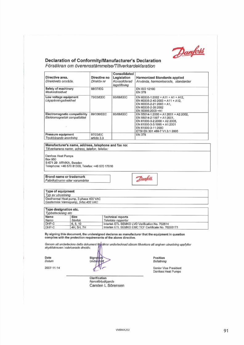
8/3/2019 Dhp Install Vmbma202 En
http://slidepdf.com/reader/full/dhp-install-vmbma202-en 91/96
91VMBMA202

8/3/2019 Dhp Install Vmbma202 En
http://slidepdf.com/reader/full/dhp-install-vmbma202-en 92/96
92 VMBMA202

8/3/2019 Dhp Install Vmbma202 En
http://slidepdf.com/reader/full/dhp-install-vmbma202-en 93/96
93VMBMA202

8/3/2019 Dhp Install Vmbma202 En
http://slidepdf.com/reader/full/dhp-install-vmbma202-en 94/96
94 VMBMA202

8/3/2019 Dhp Install Vmbma202 En
http://slidepdf.com/reader/full/dhp-install-vmbma202-en 95/96
95VMBMA202

8/3/2019 Dhp Install Vmbma202 En
http://slidepdf.com/reader/full/dhp-install-vmbma202-en 96/96