development of uav tracking and coordinate detection
TRANSCRIPT

Article 1
Development of UAV Tracking and Coordinate 2
Detection Method Using a Dual-Axis Rotary Platform 3
for an Anti-UAV System 4
Bor-Horng Sheu1, Chih-Cheng Chiu2, Wei-Ting Lu, Chu-I Huang1 and Wen-Ping Chen1,3,* 5
1Department of Electrical Engineering, National Kaohsiung University of Sciences and Technology 6 2Engineering Science and Technology, College of Engineering, National Kaohsiung University of Sciences 7
and Technology 8 3Ph.D Program in Biomedical Engineering, Kaohsiung Medical University 9
*Corresponding author: Wen-Ping Chen ([email protected]) 10
Abstract: The rapid development of multicopters has led to many security problems. In order to 11
prevent multicopters from invading restricted areas or famous buildings, an Anti-UAV Defense 12
System (AUDS) has been developed and become a research topic of interest. Topics under research 13
in relation to this include electromagnetic interference guns for unmanned aerial vehicles (UAVs), 14
high-energy laser guns, US military net warheads, and AUDSs with net guns. However, these 15
AUDSs use either manual aiming or expensive radar to trace drones. This research proposes a dual-16
axis mechanism with drone automatic tracing. The tracing platform uses visual image processing 17
technology to trace and lock the dynamic displacement of a drone. When a target drone is locked, 18
the system uses a multi-axis attitude meter and laser rangers to measure its flight altitude and 19
calculates its longitude and latitude coordinates through sphere coordinates to provide drone 20
monitoring for further defense or attack missions. Tracing tests of drone flights in the air were 21
carried out using a DJI MAVIC UAV at a height of 30 meters to 100 meters. It was set up for drone 22
image capture and visual identification for tracing under various weather conditions by a thermal 23
imaging camera and a full-color camera respectively. When there was no cloud during the daytime, 24
the images acquired by the thermal imaging camera and full-color camera provide a high-quality 25
image identification result. However, under dark weather, black clouds will emit radiant energy 26
and seriously affect the capture of images by a thermal imaging camera. When there is no cloud at 27
night, the thermal imaging camera performs well in drone image capture. When the drone is traced 28
and locked, the system can effectively obtain the flight altitude and longitude and latitude 29
coordinate values. 30
Keywords: drones; dynamic coordinate tracing; computer vision; Anti-UAV Defense System 31
I. Introduction 32
Since Dà-Jiāng Innovations (DJI) released the new DJI XP3.1 (a flight control system) [1,2], its 33
multi-rotor drone has been characterized by hovering, route-planning, its comparative low price and 34
easy of use [3, 4]. These factors have led to the rapid development of drones in the consumer selfie 35
drone market. At present, they have been adopted all over the world in environmental aerial 36
photography or surveillance. However, under uncontrolled drone flight control, there have been 37
many drone misfortunes, both at home and abroad. News events have included the impact on the 38
navigation area, the impact on famous buildings, and the horror of political figures, and the biggest 39
worry for drones is that people or terrorists may modify them to make them carry dangerous bombs, 40
or use the vehicles themselves as extremely dangerous devices for attacking bombs. drone hidden 41
hazards are an urgent problem [5, 6], so countries have begun to impose strict regulations on drone 42
flight management, and even implement no-fly rules. The Federal Aviation Administration (FAA), 43
similar authorities of China and Taiwan have all drawn up drone system usage scenarios. Besides, 44
for the sake of preventing and controlling indecent invasions by drones, research into many AUDSs 45
Preprints (www.preprints.org) | NOT PEER-REVIEWED | Posted: 16 June 2019 doi:10.20944/preprints201906.0146.v1
© 2019 by the author(s). Distributed under a Creative Commons CC BY license.
Peer-reviewed version available at Appl. Sci. 2019, 9, 2583; doi:10.3390/app9132583

2 of 17
has progressively turned into an international research topic of interest [7, 9]. There are lots of similar 46
approaches of AUDS, such as spoofing attacks, tracing and in time warning, detection, defeating, and 47
signal interfering [10, 11]. The Scalable Effects Net Warhead invented by the US military launches 48
warheads and throws nets to attack enemy drones, and other anti-UAV technologies developed by 49
scientists. Among them, devices such as radar, satellites and thermal imaging cameras are used for 50
in time warning and detection which detect the trace of a drone from the ground. Those technologies 51
are to carry out an immediate detection, warning, and tracing of the intruding drone, and provide 52
real time messages and information support [12, 15]. Destroying intruding drones is another kind of 53
approach which acquires the location of drones first and then defeat them by using missiles, lasers or 54
other weapons. An example of this type of approach is a defence system using strong energy laser 55
developed by a Turkish company ASELSAN. Even if this method with the effect of destruction and 56
threat, there is a chance of incident injury to adjacent matters while the drone is gotten down. 57
Interfering with communications of an intruding drone by electromagnetic interference methods is 58
effective; however, it also affects the surrounding communications. The shortcoming is clear thus the 59
wireless communications around that area is affected. The quality of life will also be influenced. The 60
Scalable Effects Net Warhead is a technique for quickly and accurately delivering a net to a remote 61
target using a projectile. It includes a mesh-containing launcher, an ejection spring, and a releasable 62
ogive. This net warhead can be launched from a suitable barrel using a propellant or compressed gas. 63
The speed and rotation of the warhead will be determined by the diameter of the barrel. When the 64
warhead approaches the target, the electronic control board activates the servo motor and then pulls 65
the central locking plunger to release the ogive. Then the spring pushes the net to aim at and spread 66
on the target resulting in its capture. 67
There are lots of reports of security issues caused by drone incidents. Lots of incidents reported 68
that terrorists around the world use drones to attack the targets. Thus there are an increasing market 69
and insistent need for AUDS which lead to the development of AUDS technologies. However, with 70
limited resources, how to develop AUDS detection technologies for civil purposes is a very important 71
research topic. This research proposes a two-axis rotary tracing mechanism which adopts a thermal 72
imaging camera and a full-color camera. With an algorithm of image identification, this device traces 73
and locks a drone. The device traces a drone while the drone is in the range of visual detection by 74
tracing of dynamic coordinates. A multi-axis attitude meter and laser rangers in the proposed device 75
are used to perform the sensing then calculate its flight altitude of the drone. The spherical 76
coordinates are used to obtain the longitude and latitude data of the drone. Through continuous 77
locking the dynamic coordinates of the drone, a ground control station arranges an attack drone to 78
defeat the target drone by a net gun, laser gun or other weapons such as rifles. In this stage, a real-79
time transmitting the dynamic coordinate to an attack drone for fast chase is required. This paper 80
proposes a different approach. 81
II. System Architecture 82
The research structure of this paper consists of three units: the two-axis mechanism, drone 83
identification and tracing approach, and drone three-dimensional coordinate calculation method. A 84
detailed description of each unit follows: 85
Preprints (www.preprints.org) | NOT PEER-REVIEWED | Posted: 16 June 2019 doi:10.20944/preprints201906.0146.v1
Peer-reviewed version available at Appl. Sci. 2019, 9, 2583; doi:10.3390/app9132583

3 of 17
Rotation
direction
of y-axis
Rotation direction
of x-axis
Tracking platform
(including slip ring)
y-axis
bearing
x-axis bearing
Top view
Side view
Laser Rangefinder Sets
Infrared thermal
imaging camera
Full color
camera
GPS
antenna
LoRa
antenna
Rotation direction
of x-axis
86
Figure 1. Design of the two-axis mechanism. 87
1. The Two-Axis Rotational Platform Mechanism 88
The design of externals for the proposed two-axis rotational device in this research is shown in 89
Figure 1. There are two axes: the lateral axis is the x-axis and the longitudinal axis is the y-axis. With 90
the rotation of the x-axis and y-axis, the movement of the image (the picture acquired by the thermal 91
imaging or full-color camera) will be driven. The image provides flying drone detection with a 92
viewing angle range of 360°for the x-axis and 180°for the y-axis of rotation. In order to improve the 93
detection capability of the drone, there is a mechanism frame inside the two-axis mechanism which 94
is equipped with a fine-tuning device (three sets of laser rangers), a multi-axis attitude meter, a 95
thermal imaging camera, and a full-color camera for drone image capture and position detection. The 96
fine-tuning mechanism is used to provide drone tracing, and the laser rangefinder is adopted for 97
focusing precision adjustment. In the drone image focus and distance measurement, because the 98
image acquisition lens and the laser rangefinder are not on the same line, the distance measuring of 99
the drone for high-altitude flight needs the fine-tuning mechanism for the focus. First, the 100
photographic lens is adopted as the focus point of the center of the image frame, then the three laser 101
rangers are set close to the lens, before the fine-tuning mechanism is modified with the focus distance 102
of the drone to be acquired by the tracing device, so that the hitting spot of the laser ranger on the 103
drone overlaps with the spot of the center of the image. GPS and LoRa antennas are placed outside 104
the tracing device due to the need to avoid metal disturbance and object signal-shelter from the thick 105
casing of the tracing device. 106
2. Drone Visual Image Tracing Method 107
The drone image visual tracing process identifies a drone in motion using images acquired by a 108
thermal imaging camera or full-color camera. These cameras inside a two-axis mechanism were 109
adopted for image acquisition in this study. After image acquired, vision image processing is 110
performed and then drone tracing is done through motor control of the above platform. 111
Preprints (www.preprints.org) | NOT PEER-REVIEWED | Posted: 16 June 2019 doi:10.20944/preprints201906.0146.v1
Peer-reviewed version available at Appl. Sci. 2019, 9, 2583; doi:10.3390/app9132583

4 of 17
Start
UAV image
capture
UAV grayscale
UAV image
filtering
Thresholding
Morphology
Detecting UAV
moving objects
Calculating the center
point of UAV
End
Y
N
Calculating the amount
of displacement
Frame
Difference
Tracking UAV
Transmitting
the amount of
displacement
112
Figure 2. Drone image tracing flowchart. 113
A two-axis tracing device adopts image processing techniques to deal with images of a dynamic 114
object. An image capture card in the device acquires pictures at a speed of 30 frames per second, and 115
then performs image processing, as shown in the image processing flowchart in Figure 2. The 116
acquisition of a dynamic drone contour [15, 16] is carried out by the frame difference method with 117
image pre-processing. The frame difference method allows extraction of a motion region [17, 18] on 118
two adjacent images by performing differential operations. It oversees the movement of anomalous 119
objects [19] in the picture with the movement of the target and the movement of the camera. There 120
will be a significant difference between adjacent frames. For real-time tracing, due to the fast drone 121
flight speed, a small amount of immediate calculation is needed to trace the drone steadily. There is 122
an advantage that the background accumulation problem for the frame difference method is almost 123
ignored. The renew speed is quick and less calculation is required for tracing a drone immediately, 124
which is shown in Figure 3(f). The formula is as follows: 125
𝐷(𝑥, 𝑦) = 𝑓𝑚+1(𝑥, 𝑦) − 𝑓𝑚(𝑥, 𝑦)………….…...…………..(1) 126
where m and (m+1) are the results of differential operations for the mth frame and (m+1)th frame. 127
(a) thermal image
acquisition (b) grayscale
(c) image filtering
Preprints (www.preprints.org) | NOT PEER-REVIEWED | Posted: 16 June 2019 doi:10.20944/preprints201906.0146.v1
Peer-reviewed version available at Appl. Sci. 2019, 9, 2583; doi:10.3390/app9132583

5 of 17
(d) Threshold processing (e) Dilation processing (f) Frame difference method
processing
Figure 3. Drone image acquisition procedures. 128
(x1, y1)
(x2, y2)
(Center)
x-axis
y-axis
(x0, y0)
(Concentric)
129
Figure 4. Diagram of the target drone displacement vector. 130
The drone tracing mechanism of a two-axis tracing device is to convert a two-dimensional 131
variation of the pixels of a captured image (∆x, ∆y) into a step-level control amount of a two-axis step 132
motor inside the above device. A movement amount is calculated by the above conversion of 133
acquired images, which is applied to complete drone tracing operations. Suppose the image’s 134
resolution is set as 2P×2Q pixels, which is shown in Figure 4. An acquired screen image’s origin point 135
is set as (𝑥0, 𝑦0), and its pixel coordinate is (-P, -Q). The screen’s center point is (𝑥1, 𝑦1), which is the 136
concentric point in the tracing screen, and its pixel coordinate is defined as (0, 0). Therefore, the pixel 137
of the screen image in the x-axis ranges from -P~+P, and the y-axis ranges from -Q~+Q. When the 138
target drone’s image enters the edge of the rectangular frame of the tracing device, it is acquired by 139
the visual identification of the system. The tracing system instantly estimates the pixel difference (p, 140
q) between the x-axis and the y-axis of the center position (𝑥2, 𝑦2) and the concentric point (𝑥1, 𝑦1) 141
of the drone: (𝑥2 − 𝑥1, 𝑦2 − 𝑦1). When the p value is positive, it reveals that the center point of target 142
drone is on the right side of the center point of the screen image, and vice versa for the left side. 143
Furthermore, when the q value is positive, it reveals that the center point of the target drone is on the 144
lower side of the center point of the screen image, and vice versa. 145
In order to trace the invading drones dynamic position at any time, three-dimensional 146
coordinate parameters such as the flight altitude of the drone and its longitude and latitude are 147
calculated, and these parameters are immediately transmitted to the ground monitoring center for 148
direct attack or indirect hunt for the drone. The control requirements for a two-axis step motor in the 149
two-axis tracing device are as follows: 150
Preprints (www.preprints.org) | NOT PEER-REVIEWED | Posted: 16 June 2019 doi:10.20944/preprints201906.0146.v1
Peer-reviewed version available at Appl. Sci. 2019, 9, 2583; doi:10.3390/app9132583

6 of 17
Suppose the position of the concentric point of the screen image is (𝑥1, 𝑦1) and the position of 151
the drone is (𝑥2, 𝑦2), which are shown in Figure 4. The system traces the drone in real time, and the 152
requirement of motor control speed of the two-axis device is: 153
𝑉𝑥 =𝑝
∆𝑡, 𝑉𝑦 =
𝑞
∆𝑡……………………...…………..(2) 154
where ∆t is the time for the duration of the image capture card to acquire images, which is normally 155
30 frames per second; that is, ∆t=1/30 second. The smaller the value of ∆t, the more accurately the 156
tracing system can grasp the drone movement trajectory, so that the alignment screen’s concentric 157
point of the tracing device can lock the drone as soon as possible, but relatively requires a faster 158
software computing requirement. 159
The system has to convert the pixel difference (p, q) of the image into the tracing step angle of 160
the two-axis step motor of the tracing device, that is, the image coordinates are converted from pixel 161
values (p, q) to the number of steps (Sp, Sq) to drive the two-axis step motor, where Sp and Sq represent 162
the step numbers of the step motor for the x-axis and y-axis, respectively. Since the step motor rotates 163
360°in one turn, assuming that SR is the total number of steps in one circle of the step motor, the step 164
angle 𝜃𝑚 of each step motor is: 165
𝜃𝑚 =3600
𝑆𝑅………………………………...…………..(3) 166
Previous image Image after displacement
Sp step of motor
displacement
Two images overlapping
p pixel shifting of image corresponding
to Sp steps for step motor right shifting
(a) (b)
(c)
p
167
Figure 5. Schematic diagram of the relationship between the step angle and image. 168
Due to the necessary 𝜃𝑚 value of the step motor in the tracing device is related to the pixel value 169
acquired by the image capture card, it is important to find the correlation between these two matters. 170
First, suppose the full-color (or thermal imaging) camera acquire the picture in a certain direction as 171
shown in Figure 5(a). Then, suppose the driver of the step motor in the tracing device send the square 172
wave signal with the number of SP to the step motor of the x-axis, which drives the step motor of the 173
x-axis to carry out the rotation of SP steps. These make the two-axis device carry out a horizontal right 174
movement, and then acquires the immediate picture, as shown in Figure 5(b). Finally, by comparing 175
the images of Figure 5(a) and Figure 5(b) with the superimposed image and calculating the increment 176
of the p-value of these two images of the x-axis after the step motor of the x-axis rotates steps of Sp, 177
Preprints (www.preprints.org) | NOT PEER-REVIEWED | Posted: 16 June 2019 doi:10.20944/preprints201906.0146.v1
Peer-reviewed version available at Appl. Sci. 2019, 9, 2583; doi:10.3390/app9132583

7 of 17
as shown in Figure 5(c), the tracing system can receive the number of steps 𝑝𝑆 of the step motor 178
necessary for each pixel in the x-axis direction: 179
𝑝𝑆 =𝑆𝑝
𝑝………………….………..…...…………..(4) 180
Furthermore, the number of steps of the step motor necessary for each pixel in the y-axis 181
direction is 𝑞𝑆. 182
𝑞𝑆 =𝑆q
𝑞……………………………....…………..(5) 183
3. Drone Three-Dimensional Coordinate Calculation 184
(1) Detection method for drone height: The rotation direction and angle judgment mode of the 185
two-axis tracing device are based on the value sensed from multi-axis attitude meters. Therefore, 186
there is a close relationship between the placement position of the attitude meter and the accuracy of 187
the system data. The starting point of orientation determination by an attitude sensing component is 188
based on the preset position of its own module. The drone movement orientation of the screen image 189
is based on the movement of the lens, so the position of the sensing component of the attitude meter 190
should be placed as close as possible to the camera lens, so that the angular deviation will be smaller. 191
After many tests, we found that it has the best effect when placed under the lens. 192
θ
Rotation direction
of y-axis
(x2, y2)
(x1, y1) Laser
Rangefinder
Attitude
Indicator
h
Elevation angle
193
Figure 6. Schematic diagram of the calculation of the height of the drone on the image concentric point 194
by the attitude meter and the laser ranger. 195
When the tracing device finds that the drone has entered the visual image of the screen as in 196
Figure 6, the system immediately traces the drone image in the screen through visual identification, 197
and computes the relative relationship between the drone image and the center point of the visual 198
image screen. Then, it performs an action of target drone tracing and position locking. The drone 199
image enters the center point (𝑥1, 𝑦1) of the visual image screen of the tracing device, and the laser 200
rangefinder can measure when the target drone enters the laser ranging range. The distance value (r) 201
from the target is obtained, and the elevation angle (θ) of the rotating stage at this time is obtained 202
by the multi-axis attitude meter in the apparatus. As shown in formula (6), the flight altitude h of the 203
drone can be converted. 204
Preprints (www.preprints.org) | NOT PEER-REVIEWED | Posted: 16 June 2019 doi:10.20944/preprints201906.0146.v1
Peer-reviewed version available at Appl. Sci. 2019, 9, 2583; doi:10.3390/app9132583

8 of 17
ℎ = 𝑟 × 𝑠𝑖𝑛θ = √(𝑥2 − 𝑥1)2 + (𝑦2 − 𝑦1)2 × 𝑠𝑖𝑛𝜃 …………..(6) 205
ψ
θ
WB
L
(WB, JB )
(WA, JA)
(0, 0 ) (0, JB)JB
D
Equator
Prime Meridian
206
Figure 7. Schematic diagram of the longitude and latitude sphere coordinate algorithm for the drone. 207
(2) Detection method for drone longitude and latitude coordinate as well as azimuth: When the 208
tracing system locks the target drone to the center point position (𝑥1, 𝑦1) of the image screen through 209
tracing, the target drone has entered the laser ranging range. The values of the distance and the 210
horizontal elevation angle of the target drone from the test site can be obtained by laser rangers and 211
the attitude meter of the two-axis device, and then the longitude and latitude, and the azimuth angle 212
(relative to the north angle), of the drone can be analyzed. In this paper, the drone longitude and 213
latitude coordinates [20, 21] can be obtained by using the target coordinate conversion formula. A 214
schematic diagram of the longitude and latitude coordinate algorithm of the target drone is shown 215
in Figure 7. This algorithm is applicable to the distance calculation between any two points on the 216
spherical surface, where O is the center point of the sphere, and A and B are any two points on the 217
sphere. Point A represents the longitude and latitude coordinates (WA, JA) obtained by the GPS in the 218
dual-axis tracing platform, and point B represents the unknown longitude and latitude coordinates 219
(WB, JB) of the drone traced by the dual-axis tracing platform. The longitude and latitude coordinates 220
of point B can be obtained by the sphere longitude and latitude coordinate conversion [21]. Other 221
parameters are as follows: 222
Point G: the true north position of the sphere; point O: center of the sphere; R: average radius of 223
the earth (~6371 km); 224
(WA, JA): the value of the longitude and latitude of point A obtained by the GPS of the two-axis 225
device; 226
ψ (Azimuth angles of point A, B and G): obtained by the magnetometer and gyroscope of the 227
multi-axis attitude meter in the two-axis device; 228
∠a: the angle between the two points B and G and the ground connection 𝐺𝑂̅̅ ̅̅ ; 229
∠b: the angle between the two points A and G and the ground connection 𝐺𝑂̅̅ ̅̅ ; 230
∠c: the angle between the two points A and B and the ground connection 𝐺𝑂̅̅ ̅̅ ; 231
𝐴�̂�: the spherical distance between the two points of point A (two-axis device) and B (drone 232
aerial location); that is, the length of minor arc 𝐴�̂� in the arc generated by the intersection of the 233
planes passing through the three points A, O and B and the ball. 234
∠c is the metric angle: 235
∠c = 𝐴�̂�
𝑅×
1800
𝜋 (7) 236
Preprints (www.preprints.org) | NOT PEER-REVIEWED | Posted: 16 June 2019 doi:10.20944/preprints201906.0146.v1
Peer-reviewed version available at Appl. Sci. 2019, 9, 2583; doi:10.3390/app9132583

9 of 17
Since the spherical distance between point A (two-axis device) and point B (drone aerial location) 237
is much smaller than the length of R, the spherical distance 𝐴�̂� between two points can be 238
approximated as the linear distance between two points 𝐴𝐵̅̅ ̅̅ , so formula (7) can be corrected to: 239
∠c = 𝐴𝐵̅̅ ̅̅
𝑅×
1800
𝜋 (8) 240
∠a and ∠θ can be converted by the sphere longitude and latitude coordinates [21], and formula 241
(9) and formula (10) can be obtained as follows, 242
∠𝑎 = 𝑐𝑜𝑠−1(𝑠𝑖𝑛𝐴𝑤 × 𝑐𝑜𝑠∠𝑐 + 𝑐𝑜𝑠𝐴𝑤 × 𝑠𝑖𝑛∠𝑐 × 𝑐𝑜𝑠ψ) (9) 243
∠𝜃 = 𝑠𝑖𝑛−1 (𝑠𝑖𝑛𝑐×𝑠𝑖𝑛ψ
𝑠𝑖𝑛𝑎) (10) 244
Since the drone flight altitude at point B is within a few kilometers above the ground, the length 245
between the two points A and B and the point O of the center of earth can be regarded as the same, 246
and ∠θ can be regarded as the longitude difference between the two points A and B. Thus, the value 247
of the longitude and latitude of point B (WB, JB) is the longitude and latitude coordinates of drone, 248
where: 249
WB= 900 − ∠𝑎 (11) 250
𝐽𝐵 = 𝐽𝐴 + ∠𝜃 (12) 251
As described above, the longitude and latitude values of the drone flying in the air, which is 252
locked by the two-axis device and the flight altitude h, can be calculated and acquired, then 253
transmitted wirelessly to the ground control center for the attack tasks of direct attack or tracing and 254
entrapping. 255
III. Experimental Results and Discussion 256
The drone tracing test results of the two-axis device, software and hardware used in the study 257
are as follows: 258
1. Development environment of the software and hardware: 259
(1) Visual identification software development: This study uses OpenCV (Open Source 260
Computer Vision Library), which is a library application software for computer vision and machine 261
learning. It was originally initiated and developed by the Intel Corporation and distributed under 262
the license of BSD (Berkeley Software Distribution license). It can be used free of charge in business 263
and research. OpenCV includes many image processing functions, machine learning algorithms, and 264
libraries for computer vision applications. 265
(2) Sensors and imaging equipment: 266
• Infrared thermal imaging: As shown in Figure 8, this paper uses a intermediate level 267
infrared thermal imaging camera (TE–EQ1), which is equipped with a 50 mm fixed-268
focus lens with 384×288 pixels. It can be used for mobile tracing tests with a drone flying 269
altitude of about 100 meters. The TE–EQ1 is capable of observing the distribution of heat 270
sources in drones, providing users with drone tracing tasks through computer vision 271
technology. 272
Preprints (www.preprints.org) | NOT PEER-REVIEWED | Posted: 16 June 2019 doi:10.20944/preprints201906.0146.v1
Peer-reviewed version available at Appl. Sci. 2019, 9, 2583; doi:10.3390/app9132583
10 of 17
273
Figure 8. TE–EQ1 infrared thermal imaging device. 274
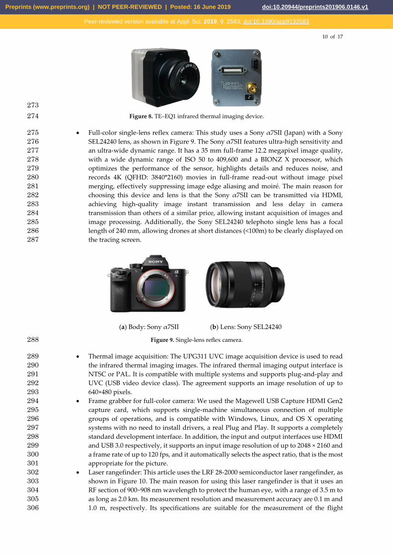
• Full-color single-lens reflex camera: This study uses a Sony α7SII (Japan) with a Sony 275
SEL24240 lens, as shown in Figure 9. The Sony α7SII features ultra-high sensitivity and 276
an ultra-wide dynamic range. It has a 35 mm full-frame 12.2 megapixel image quality, 277
with a wide dynamic range of ISO 50 to 409,600 and a BIONZ X processor, which 278
optimizes the performance of the sensor, highlights details and reduces noise, and 279
records 4K (QFHD: 3840*2160) movies in full-frame read-out without image pixel 280
merging, effectively suppressing image edge aliasing and moiré. The main reason for 281
choosing this device and lens is that the Sony α7SII can be transmitted via HDMI, 282
achieving high-quality image instant transmission and less delay in camera 283
transmission than others of a similar price, allowing instant acquisition of images and 284
image processing. Additionally, the Sony SEL24240 telephoto single lens has a focal 285
length of 240 mm, allowing drones at short distances (<100m) to be clearly displayed on 286
the tracing screen. 287
(a) Body: Sony α7SII (b) Lens: Sony SEL24240
Figure 9. Single-lens reflex camera. 288
• Thermal image acquisition: The UPG311 UVC image acquisition device is used to read 289
the infrared thermal imaging images. The infrared thermal imaging output interface is 290
NTSC or PAL. It is compatible with multiple systems and supports plug-and-play and 291
UVC (USB video device class). The agreement supports an image resolution of up to 292
640×480 pixels. 293
• Frame grabber for full-color camera: We used the Magewell USB Capture HDMI Gen2 294
capture card, which supports single-machine simultaneous connection of multiple 295
groups of operations, and is compatible with Windows, Linux, and OS X operating 296
systems with no need to install drivers, a real Plug and Play. It supports a completely 297
standard development interface. In addition, the input and output interfaces use HDMI 298
and USB 3.0 respectively, it supports an input image resolution of up to 2048 × 2160 and 299
a frame rate of up to 120 fps, and it automatically selects the aspect ratio, that is the most 300
appropriate for the picture. 301
• Laser rangefinder: This article uses the LRF 28-2000 semiconductor laser rangefinder, as 302
shown in Figure 10. The main reason for using this laser rangefinder is that it uses an 303
RF section of 900~908 nm wavelength to protect the human eye, with a range of 3.5 m to 304
as long as 2.0 km. Its measurement resolution and measurement accuracy are 0.1 m and 305
1.0 m, respectively. Its specifications are suitable for the measurement of the flight 306
Preprints (www.preprints.org) | NOT PEER-REVIEWED | Posted: 16 June 2019 doi:10.20944/preprints201906.0146.v1
Peer-reviewed version available at Appl. Sci. 2019, 9, 2583; doi:10.3390/app9132583

11 of 17
altitude of the short-range drones in this study, and its significant distance measurement 307
accuracy can be used as a basis for testing the drone flight altitude. 308
309
Figure 10. Laser rangefinder LRF 28-2000B. 310
• Multirotor: At present, the market share of multirotors is dominated by DJI Dajiang 311
Innovation. With its drone, which is lightweight, portable and has a small volume being 312
sold at a friendly proce, it is very popular among people generally. Additionally, the 313
news media have reported that most drone events have involved drones from DJI 314
Dajiang Innovation, so this study uses the DJI Mavic Pro multirotor as the main tracing 315
target of the experiment. 316
2. Development of Hardware for the Two-Axis Device 317
To make it shockproof, robust and waterproof, the outer material of the two-axis device of this 318
paper is made of Teflon. It is equipped with two sets of step motors (including its step motor driver). 319
These two step motors respectively control the up and down elevation angle and the movement of 320
the left and right rotation of the two-axis device. The pixels of full-color image used in this device are 321
640×480; that is, P=640 and Q=480, and a two-phase step motor 𝑆𝑅 = 10,000 is used; that is, 𝜃𝑚 =322
0.036. The test height of drone tracing is 10~100 meters, and the radius of the two-axis device is 323
a=0.25m. The maximum flight speed of the drone is 20km/hr. As a result the maximum rotation speed 324
of the two-axis device is 𝑉𝑟,𝑚𝑎𝑥 =𝑎
𝑅𝑚𝑖𝑛× 𝑉𝑢𝑎𝑣 ≈ 0.139(𝑚/𝑠). 325
Figure 11 (a) shows the two-axis tracing device, and Figure 11 (b) shows the hardware structure 326
inside the two-axis tracing device. Figure 11 (c) shows the focus fine-tuning structure diagram for the 327
laser ranger. 328
Laser
Rangefinder
Full color camera
Infrared thermal imager
SMA adapter for GPS\LoRaWire gathering of HDMI, SMA,
RCA, Micro USB and Power
Image output contact/
Control board input contact/
System power contact
Camera focus motor
RS232 adapter for
thermal imager
(a) The two-axis tracing device (b) appearance of the front view of the image lens/laser ranger
Preprints (www.preprints.org) | NOT PEER-REVIEWED | Posted: 16 June 2019 doi:10.20944/preprints201906.0146.v1
Peer-reviewed version available at Appl. Sci. 2019, 9, 2583; doi:10.3390/app9132583

12 of 17
Turn left
Turn right
Turn down Turn up
Lens rotation direction
Screw forward rotation
lens upside up
Screw forward rotation
lens down
Screw forward rotation
lens left-handed
Screw forward rotation
lens right-handed
(c) picture of the focus fine-tuning configuration of the laser ranger
Figure 11. The inner hardware structure of the two-axis tracing device. 329
The main control board of the two-axis tracing device is shown in Figure 12(a), and the motor 330
control unit is shown in Figure 12(b). 331
(a) main control board (b) motor control board
Figure 12. 3D simulation and physical circuit picture of the main control unit and motor control unit. 332
3. Drone Image Identification and Tracing Test in Different Weather Environments 333
This paper uses the DJI Mavic Pro four-axis drone to achieve tracing tests of drone flight in all 334
kinds of weather. The results of tracing tests on sunny days and at flight altitudes of about 70–105 335
meters are shown in Figure 13. At more than 102 meters, drone movement cannot be determined 336
(restricted by the resolution of the full-color camera). The test results of various weather conditions–337
–sunny, cloudy, and rainy–– are shown in Figure 14, Figure 15, and Figure 16. The detailed test 338
description is as follows: 339
(a) ) The distance is 72 m (b) The distance is 86 m
Preprints (www.preprints.org) | NOT PEER-REVIEWED | Posted: 16 June 2019 doi:10.20944/preprints201906.0146.v1
Peer-reviewed version available at Appl. Sci. 2019, 9, 2583; doi:10.3390/app9132583

13 of 17
(c) The distance is 94 m (d) The distance is 102 m
Figure 13. Tests of drone flight altitudes (on a sunny day). 340
(1) Sunny environment: As shown in Figure 14, the capture effects of the drone's image on sunny 341
days are different based on different brightness and sunshade levels due to different conditions. In 342
the case of large changes in ambient brightness, the effect of light on the lens and tracing is quite 343
large. In addition, the size of the drone is small, which can cause the phenomenon that the target 344
drone is lost while in image processing, and then recovered. 345
(a) (b) (c)
(d) (e) (f)
Figure 14. Results of the tracing test on sunny days (drone flight altitude is 105 m). 346
(2) Cloudy environment: Figure 15 shows the acquisition effects of the drone's image on cloudy 347
days. The cloudy background is clean and free of other interference. In addition, the difference in 348
gray scale presented by the sky is not obvious, making the tracing target more significant. The tracing 349
effect was good, and the target drone was not easy to lose. 350
(a) (b) (c)
Preprints (www.preprints.org) | NOT PEER-REVIEWED | Posted: 16 June 2019 doi:10.20944/preprints201906.0146.v1
Peer-reviewed version available at Appl. Sci. 2019, 9, 2583; doi:10.3390/app9132583

14 of 17
(d) (e) (f)
Figure 15. Results of the tracing test on cloudy days (drone flight altitude is 130 m). 351
(3) Rainy environment: Figure 16 shows the acquisition effects of the drone's image on rainy 352
days. In general, no drone appears on rainy days (a normal drone is usually not waterproof); drone 353
players usually choose to take off in clear weather. In the case of rain, the lens is susceptible to 354
raindrops. Coupled with poor vision, it is impossible to clearly present the tracing image, and it is 355
difficult to judge the target, which leads to a poor tracing effect. 356
357
Figure 16. Results of the tracing test on rainy days (drone flight altitude is 80 m). 358
4. Test of drone Tracing and Longitude and Latitude Coordinates 359
Figure 17 shows the tracing process through a full-color image. A target drone was successfully 360
hit with laser rangers in this study. Conversion of the sensed values of the multi-axis attitude meter 361
and the known longitude and latitude coordinates (WA, JA) of the GPS of the two-axis device were 362
achieved through the longitude and latitude sphere coordinate algorithm. It can be calculated that 363
when the drone is locked by the tracing system, its current longitude and latitude coordinates (WB, 364
JB) are (120.32, 22.64), and the flying altitude is 58.7 meters. 365
Preprints (www.preprints.org) | NOT PEER-REVIEWED | Posted: 16 June 2019 doi:10.20944/preprints201906.0146.v1
Peer-reviewed version available at Appl. Sci. 2019, 9, 2583; doi:10.3390/app9132583

15 of 17
366
Figure 17. Test results of the full-color tracing interface. 367
Figure 18 shows the tracing process through a thermal image. A target drone was successfully 368
hit with the laser rangers of the two-axis device. Conversion of the sensed values of the multi-axis 369
attitude meter and the known longitude and latitude coordinates (WA, JA) of the GPS of the device 370
were achieved through the longitude and latitude sphere coordinate algorithm. It can be calculated 371
that when the drone is locked by the tracing system, its current longitude and latitude coordinates 372
(WB, JB) are (120.32, 22.64) and the flying altitude is 51.9 meters. 373
374
Figure 18. Test results of thermal imaging tracing interface. 375
IV. Conclusion 376
As the number of drones increases, so does the risk to flight safety. It is only a matter of time 377
before a drone is used to attack aircrafts to cause damage. Governments are worried that the 378
increasing number of amateur drones will lead to more flight accidents. Therefore, many 379
governments now regulate drone registration, driver's license regulations, and so forth, and also limit 380
flight range and maximum flight altitude. In addition, various anti-UAV systems have been 381
proposed, but these AUDS either use manual aiming or expensive radar for tracing drones. This 382
Preprints (www.preprints.org) | NOT PEER-REVIEWED | Posted: 16 June 2019 doi:10.20944/preprints201906.0146.v1
Peer-reviewed version available at Appl. Sci. 2019, 9, 2583; doi:10.3390/app9132583

16 of 17
study uses two sets of step motors with a thermal imaging camera/full-color camera and sensing 383
module for the dynamic tracing of drone flying at high altitudes, and measurement of its three-384
dimensional coordinates, which makes it a low-cost and practical drone tracing device for anti-UAV 385
systems. Future research will combine an attack drone and a net gun with a throwing function to 386
provide a safe anti-UAV system with tracing and capturing of drones. 387
Acknowledgements: The team would like to express sincere thanks to the Ministry of Science and Technology 388
and Southern Taiwan Science Park Bureau of Taiwan. Without their support, this work will not be done. The 389
project numbers are MOST 107-2622-E-992 -006 -CC2 and 107B19. 390
References 391
[1] Wai Fong Boh, Wee-Kiat Lim and Yi Zeng, “Da Jiang Innovations (DJI): the rise of the drones,” the Asian 392
Business Case Centre-Nanying Technology University Singapore, pp.1-28, 2017. 393
[2] Kelly Sze Hiu Chin, Alex Chun Yin Siu, Stanley Yau Kit Ying, and Yifan Zhang, “Da Jiang Innovation, DJI: 394
The Future of Possible,” ACADEMY OF ASIAN BUSINESS REVIEW, Vol. 3, No. 2., pp.83-109, 2017. 395
[3] T.J. Diaz, “Lights, drone... action,” IEEE Spectrum, Volume: 52, Issue: 7, pp. 36 – 41, 2015. 396
[4] Marc Lort, Albert Aguasca, Carlos López-Martínez and Tomás Martínez Marín, “Initial Evaluation of SAR 397
Capabilities in UAV Multicopter Platforms,” IEEE Journal of Selected Topics in Applied Earth Observations and 398
Remote Sensing, Volume: 11, Issue: 1, pp. 127 – 140, 2018. 399
[5] Paul Dempsey, “View from Washington [News Comment],” Engineering & Technology, Volume: 10, Issue: 2, 400
pp.14, 2015. 401
[6] Paul Dempsey, “View from Washington [News Briefing],” Engineering & Technology, Volume: 9, Issue:9, pp.16, 402
2014. 403
[7] Miroslav Kratky and Vaclav Minarik, “The non-destructive methods of fight against UAVs,” 2017 404
International Conference on Military Technologies (ICMT), pp.690-394, 2017. 405
[8] Andrew Hull and David Markov, “Foreign Counter-Unmanned Aerial Systems: Developments in the 406
International Arms Markets,” IDA Research Notes, pp.25-33, 2017. 407
[9] Guoru Ding, Qihui Wu, Linyuan Zhang, Yun Lin, Theodoros A. Tsiftsis, and Yu-Dong Yao, “ An Amateur 408
Drone Surveillance System Based on Cognitive Internet of Things,” Amateur drone surveillance, Cognitive 409
internet of things, Unmanned aerial vehicles, Anti-drone technology, pp.1-17, 2017. 410
[10] Holland Michel, “About the Center for the Study of the Drone,” Counter-Drone System, pp.1-20, 2018. 411
[11] POP Sebastain and LUCHIAN Andrei, “Considerations Regarding Detection and Combat System for 412
UAV's,” RECENT, Volume: 18, Issue: 1(15), pp.49-55, 2017. 413
[12] Diogo Branquinho Ramos, Denis Silva Loubach, and Adilson Marques da Cunha, “Developing a distributed 414
real-time monitoring system to track UAVs,” IEEE Aerospace and Electronic Systems Magazine, Volume: 25, 415
Issue: 9, pp.18-25, 2010. 416
[13] Zhuofan Xu, Ruixuan Wei, Xiaolin Zhao, and Shulei Wang, “Coordinated Standoff Target Tracking 417
Guidance Method for UAVs,” IEEE Access, Volume: 6, pp. 59853-59859, 2018. 418
[14] Vadim Stary, Vaclav Krivanek, and Alexandr Stefek, “Optical detection methods for laser guided unmanned 419
devices,” Journal of Communications and Networks, Volume: 20, Issue: 5, pp. 464-472, 2018. 420
[16] Bor-Horng Sheu, Chih-Cheng Chiu, Wei-Ting Lu, Chun-Chieh Lien, Tung-Kuan Liu and Wen-Ping Chen, 421
“Dual-axis Rotary Platform with UAV Image Recognition and Tracking,” Microelectronics Reliability, 422
Volume 95, pp.8-17, April. 2019. 423
[15] Eija Honkavaara, Matti A. Eskelinen, Ilkka Pölönen, Heikki Saari, Harri Ojanen, Rami Mannila, Christer 424
Holmlund, Teemu Hakala, Paula Litkey, Tomi Rosnell, Niko Viljanen, and Merja Pulkkanen, “Remote 425
Sensing of 3-D Geometry and Surface Moisture of a Peat Production Area Using Hyperspectral Frame 426
Cameras in Visible to Short-Wave Infrared Spectral Ranges Onboard a Small Unmanned Airborne Vehicle 427
(UAV), IEEE Transactions on Geoscience and Remote Sensing, Volume: 54, Issue: 9, pp.5440-5454, 2016. 428
[17] Hongpeng Yin, Yi Chai, Simon X. Yang, and Xiaoyan Yang, “Fast-moving target tracking based on mean 429
shift and frame-difference methods,” Journal of Systems Engineering and Electronics, Volume: 22, Issue: 4, 430
pp.587-592, 2011. 431
[18] Bo Du, Yujia Sun, Shihan Cai, Chen Wu, and Qian Du, “Object Tracking in Satellite Videos by Fusing the 432
Kernel Correlation Filter and the Three-Frame-Difference Algorithm,” IEEE Geoscience and Remote Sensing 433
Letters, Volume: 15, Issue: 2, pp.168-172, 2018. 434
Preprints (www.preprints.org) | NOT PEER-REVIEWED | Posted: 16 June 2019 doi:10.20944/preprints201906.0146.v1
Peer-reviewed version available at Appl. Sci. 2019, 9, 2583; doi:10.3390/app9132583

17 of 17
[19] Peng Chen, Yuanjie Dang, Ronghua Liang, Wei Zhu, and Xiaofei He, “Real-Time Object Tracking on a Drone 435
With Multi-Inertial Sensing Data,” IEEE Transactions on Intelligent Transportation Systems, Volume: 19 , 436
Issue: 1, pp.131-139, 2018. 437
[20] Xu Chang and Xie Haiyan, “Notice of Retraction-Using sphere parameters to detect construction quality of 438
spherical buildings,” 2010 2nd International Conference on Advanced Computer Control, Volume: 4, pp.17-17, 439
2010. 440
[21] Homayoon Oraizi and Hadi Soleimani, “Optimum pattern synthesis of non-uniform spherical arrays using 441
the Euler rotation,” IET Microwaves, Antennas & Propagation, Volume: 9 , Issue: 9, pp. 898 – 904, 2015. 442
Preprints (www.preprints.org) | NOT PEER-REVIEWED | Posted: 16 June 2019 doi:10.20944/preprints201906.0146.v1
Peer-reviewed version available at Appl. Sci. 2019, 9, 2583; doi:10.3390/app9132583