cooperative tracking of moving targets by teams of ... · cooperative tracking of moving targets...
TRANSCRIPT
Cooperative Tracking of Moving Targets
by Teams of Autonomous Unmanned Air Vehicles
Final Report
FA9550-04-C-0107
Stephen Morris
MLB Company
Eric W. Frew
University of Colorado at Boulder
July 14, 2005
Approved for Public PRPeaseDistribution Unlimited
I Introduction
This report summarizes work by the MLB Company (industry partner) and the Research
and Engineering Center for Unmanned Vehicles at the University of Colorado at Boulder
(CU) (research institution partner) on the cooperative tracking of moving targets by
teams of autonomous unmanned air vehicles. This work was performed between
September 2004 and July 2005.
The following future scenario provides the motivation for this work: A ground vehicle
moves at high speed along a mountain road, away from a town where it committed a hit-
and-run attack on a group of civilians. The US military forces want to find the attackers
and follow them to their hideout. Multiple unmanned aerial vehicles (UAVs) are sent to
the area where the attackers were reported to have retreated. One of the UAVs identifies
the attackers' vehicle based on reports from the civilians and notifies nearby UAVs of its
location. The UAVs alter their flight paths relative to that point, with some moving
ahead of the vehicle and others maintaining position near it - without attracting attention
from the attackers. As the attackers move through the region, responsibility for direct
sensing passes from one UAV to another to always keep the target in sight. Through
collaboration, autonomous unmanned air vehicles were able to complete tasks that each
could not have done alone.
Teams of low cost unmanned aerial vehicles (UAVs) with autonomous behaviors will be
capable of performing inexpensive, persistent, distributed sensing functions such as the
one described in the preceding scenario. One application of interest is the use of UAV
teams to perform Cooperative Search, Acquisition and Tracking (CSAT) of moving
ground targets in a stealthy manner. Current state-of-the-art for autonomous control of
UAV teams enables the collaborative tracking of friendly (i.e. vehicles that provide their
GPS location and velocity and are not attempting to evade) ground vehicles, such as in
the context of a convoy protection scenario.
2
This report describes the UAV platform, control algorithm, and sensor hardware that,
based on our research, is best suited to demonstrate cooperative tracking of moving
targets.
2 UAV Platform and Sensor System
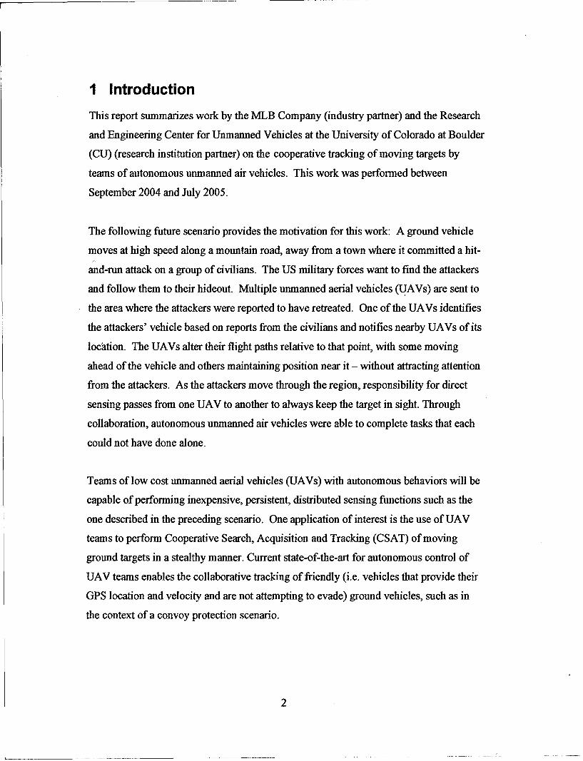
Figure 1. MLB Bat UAV System.
The MLB Bat 3 is a small, low cost, UAV system that includes an integrated,
automatically aimed, gimbal camera sensor. The Bat 3 is capable of fully autonomous
flight operation from launch through landing, has a 6 hour duration, and has been in
production since Fall 2000. The Bat 3 is launched from a car top bungee-powered
catapult and lands autonomously in a clearing 100 x 50 yards in size. The complete
system sells for $42,000 and replacement aircraft (with gimbal sensor) sell for $25,000.
For these reasons we have chosen the Bat 3 as the platform for cooperative tracking
simulations and flight demonstrations. MLB has 6 DOF dynamics models for the Bat 3
already developed and extensive flight experience with the system (over 500 hours
logged).
3
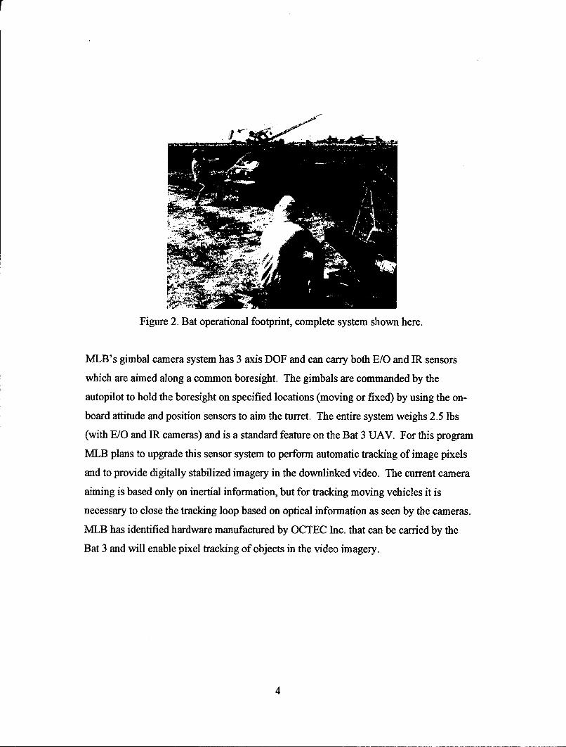
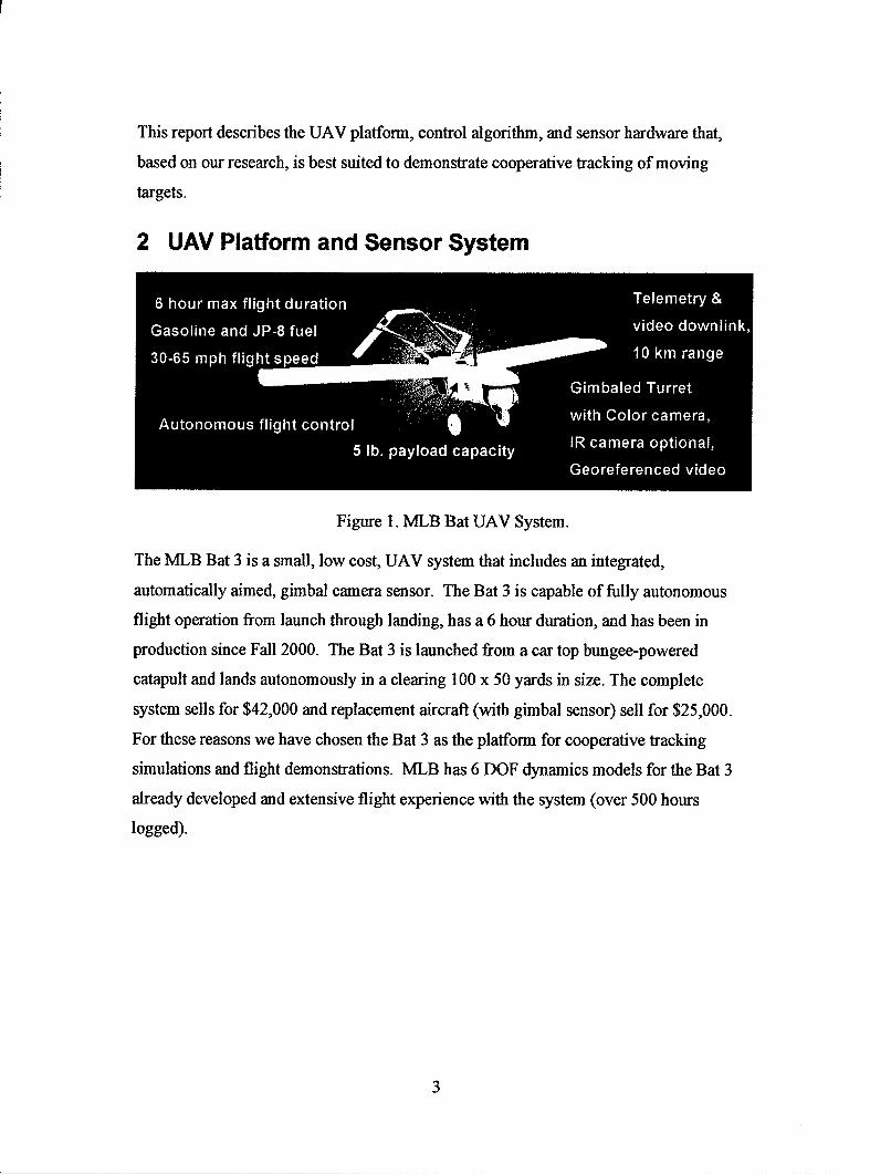
Figure 2. Bat operational footprint, complete system shown here.
MLB's gimbal camera system has 3 axis DOF and can carry both E/O and IR sensors
which are aimed along a common boresight. The gimbals are commanded by the
autopilot to hold the boresight on specified locations (moving or fixed) by using the on-
board attitude and position sensors to aim the turret. The entire system weighs 2.5 lbs
(with E/O and IR cameras) and is a standard feature on the Bat 3 UAV. For this program
MLB plans to upgrade this sensor system to perform automatic tracking of image pixels
and to provide digitally stabilized imagery in the downlinked video. The current camera
aiming is based only on inertial information, but for tracking moving vehicles it is
necessary to close the tracking loop based on optical information as seen by the cameras.
MLB has identified hardware manufactured by OCTEC Inc. that can be carried by the
Bat 3 and will enable pixel tracking of objects in the video imagery.
4
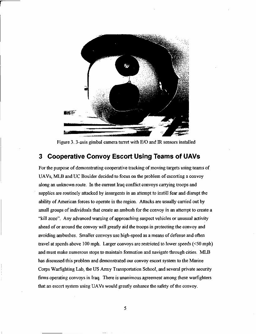
Figure 3. 3-axis gimbal camera turret with E/O and IR sensors installed
3 Cooperative Convoy Escort Using Teams of UAVs
For the purpose of demonstrating cooperative tracking of moving targets using teams of
UAVs, MLB and UC Boulder decided to focus on the problem of escorting a convoy
along an unknown route. In the current Iraq conflict convoys carrying troops and
supplies are routinely attacked by insurgents in an attempt to instill fear and disrupt the
ability of American forces to operate in the region. Attacks are usually carried out by
small groups of individuals that create an ambush for the convoy in an attempt to create a
"kill zone". Any advanced warning of approaching suspect vehicles or unusual activity
ahead of or around the convoy will greatly aid the troops in protecting the convoy and
avoiding ambushes. Smaller convoys use high-speed as a means of defense and often
travel at speeds above 100 mph. Larger convoys are restricted to lower speeds (<50 mph)
and must make numerous stops to maintain formation and navigate through cities. MLB
has discussed this problem and demonstrated our convoy escort system to the Marine
Corps Warfighting Lab, the US Army Transportation School, and several private security
firms operating convoys in Iraq. There is unanimous agreement among these warfighters
that an escort system using UAVs would greatly enhance the safety of the convoy.
5
The basic convoy escort mission is to provide continuous live imagery from around and
ahead of the convoy while maintaining the ability to task some of the UAVs to track
suspicious targets when needed. Our work will focus on developing the algorithms for
coordinating and controlling the teams of UAVs along with the system upgrades needed
for the Bat UAV to perform this mission.
Convoy Escort Mission Description and Goals
1) Follow "friendly" vehicles along a known route and provide imagery that can answer
the question: Is the road ahead/behind and sides clear?
2) Friendly vehicle's location and speed is telemetered to the UAV.
3) Friendly vehicle's route is not known to the UAV.
4) UAV may be slower and less agile than convoy.
5) Must search sufficiently far ahead of convoy to give ample warning of road status.
6) Convoy personnel can alter the footprint of the UAV escort
7) Must track an unfriendly moving target when requested.
8) UAVs must account for terrain changes and obstructions to viewing
9) Ideally, all imagery is georeferenced and assembled into an easy to use display /control
station.
Our goal for phase 2 of this work is to demonstrate a team of 5 (or more) UAVs that
accomplish this mission.
4 Known Challenges for Convoy Escort
Between February and July of 2004 MLB developed and demonstrated a convoy escort
capability for the Bat 3 UAV that enables a single UAV to coordinate its flight path and
camera aiming to automatically track a 'friendly' vehicle (Fig. 4 and Fig. 5).
6
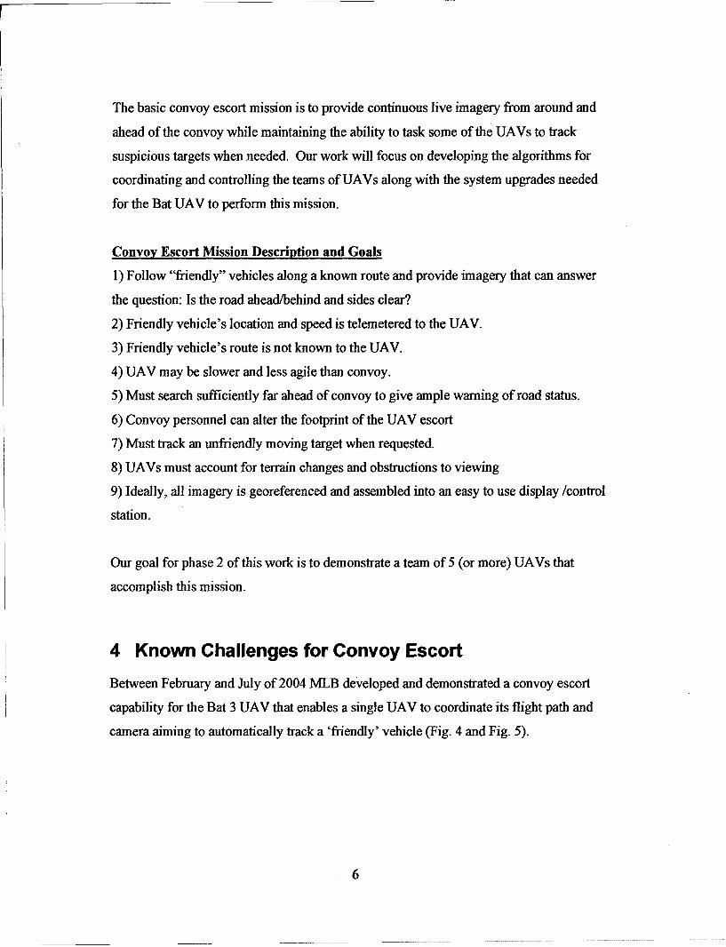
UAV Video
Vehicle GPS
Alm point offset
Figure 4. Tracking of a "friendly" vehicle with coordinated motion of the UAV and its
sensors.
44.
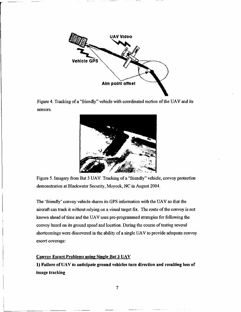
Figure 5. Imagery from Bat 3 UAV. Tracking of a "friendly" vehicle, convoy protection
demonstration at Blackwater Security, Moyock, NC in August 2004.
The 'friendly' convoy vehicle shares its GPS information with the UAV so that the
aircraft can track it without relying on a visual target fix. The route of the convoy is not
known ahead of time and the UAV uses pre-programmed strategies for following the
convoy based on its ground speed and location. During the course of testing several
shortcomings were discovered in the ability of a single UAV to provide adequate convoy
escort coverage:
Convoy Escort Problems usina Single Bat 3 UAV
1) Failure of UAV to anticipate ground vehicles turn direction and resulting loss of
image tracking
7
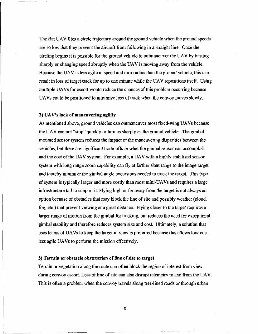
The Bat UAV flies a circle trajectory around the ground vehicle when the ground speeds
are so low that they prevent the aircraft from following in a straight line. Once the
circling begins it is possible for the ground vehicle to outmaneuver the UAV by turning
sharply or changing speed abruptly when the UAV is moving away from the vehicle.
Because the UAV is less agile in speed and turn radius than the ground vehicle, this can
result in loss of target track for up to one minute while the UAV repositions itself. Using
multiple UAVs for escort would reduce the chances of this problem occurring because
UAVs could be positioned to minimize loss of track when the convoy moves slowly.
2) UAV's lack of maneuvering agility
As mentioned above, ground vehicles can outmaneuver most fixed-wing UAVs because
the UAV can not "stop" quickly or turn as sharply as the ground vehicle. The gimbal
mounted sensor system reduces the impact of the maneuvering disparities between the
vehicles, but there are significant trade-offs in what the gimbal sensor can accomplish
and the cost of the UAV system. For example, a UAV with a highly stabilized sensor
system with long range zoom capability can fly at farther slant range to the image target
and thereby minimize the gimbal angle excursions needed to track the target. This type
of system is typically larger and more costly than most mini-UAVs and requires a large
infrastructure tail to support it. Flying high or far away from the target is not always an
option because of obstacles that may block the line of site and possibly weather (cloud,
fog, etc.) that prevent viewing at a great distance. Flying closer to the target requires a
larger range of motion from the gimbal for tracking, but reduces the need for exceptional
gimbal stability and therefore reduces system size and cost. Ultimately, a solution that
uses teams of UAVs to keep the target in view is preferred because this allows low-cost
less agile UAVs to perform the mission effectively.
3) Terrain or obstacle obstruction of line of site to target
Terrain or vegetation along the route can often block the region of interest from view
during convoy escort. Loss of line of site can also disrupt telemetry to and from the UAV.
This is often a problem when the convoy travels along tree-lined roads or through urban
8
canyons. Using multiple aircraft in different locations can provide different viewing
angles and minimize this problem.
4) Mechanical limits of the sensor's gimbal system
The Bat 3 gimbal system has a mechanical range of +135 deg yaw, +20 deg roll, and +20
-120 deg in pitch. During tests it is not uncommon to loose target track for up to 15
seconds while the aircraft reorients itself for proper gimbal aiming. By properly spacing
the UAV team around the area of interest this problem will be reduced because multiple
views of the same region are available if an aircraft reaches its gimbal's mechanical
limits.
5) Maintaining RF link with moving vehicles
Our tests so far have not used directional our tracking antennas on the ground vehicles
during convoy operations and when line of site is lost with the UAV the video signal will
often drop out. We have seen signal loss when operating along tree lined streets with the
UAV flying on one side of the convoy such that trees absorb the RF video signal. It may
be necessary for the UAV team to perform communication relay tasks in addition to
imaging for optimal convoy protection.
6) Simplified UAV user interface and data presentation for convoy operators
Having UAV operators located inside moving convoys creates a new paradigm for
information gathering and is one that has not been fully tested. Our initial experiments
indicate that the interface between the operator and the UAV must be very simple to
avoid operator overload. Similarly, the tools used to display information gathered by the
UAVs must be simple to use and intuitive, or else the situation ahead of the convoy can
not be adequately assessed in time.
7) Maintaining an appropriate lead distance ahead of the convoy
The lead UAV(s) must fly far enough ahead of the convoy to allow proper assessment
and planning based on the data received. In order to provide a lead-time of one minute at
highway speeds the UAV must fly at least 1 mile ahead of the convoy. When flying
9
along an unknown route this often results in the UAV being off course because the
aircraft doesn't know what "1 mile ahead" really means when the convoy may turn at any
moment. The convoy route is typically known when traveling at high speeds and this
information could be shared with the UAV team to properly position the lead planes.
Multiple UAVs flying ahead of the convoy will provide better coverage than using a
single aircraft for the case of unknown routes.
In most all cases, teams of cooperating UAVs provide a solution to these known
challenges in the convoy escort mission. Cooperation will also allow the team to perform
multiple tasks such as convoy escort and tracking of suspicious vehicles. Listed below is
a summary of factors that encourage cooperation between UAVs while escorting or
tracking.
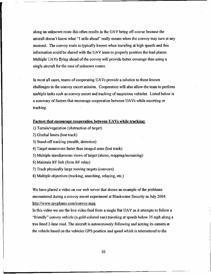
Factors that encourage cooperation between UAVs while tracking:
1) Terrain/vegetation (obstruction of target)
2) Gimbal limits (lost track)
3) Stand-off tracking (stealth, detection)
4) Target maneuvers faster than imaged zone (lost track)
5) Multiple simultaneous views of target (stereo, mapping/mosaicing)
6) Maintain RF link (form RF relay)
7) Track physically large moving targets (convoys)
8) Multiple objectives (tracking, searching, relaying, etc.)
We have placed a video on our web server that shows an example of the problems
encountered during a convoy escort experiment at Blackwater Security in July 2004:
http://www.spyplanes.com/convoy.mpg
In this video we see the live video feed from a single Bat UAV as it attempts to follow a
"friendly" convoy vehicle (a gold-colored van) traveling at speeds below 35 mph along a
tree lined 2-lane road. The aircraft is autonomously following and aiming its camera at
the vehicle based on the vehicles GPS position and speed which is telemetered to the
10
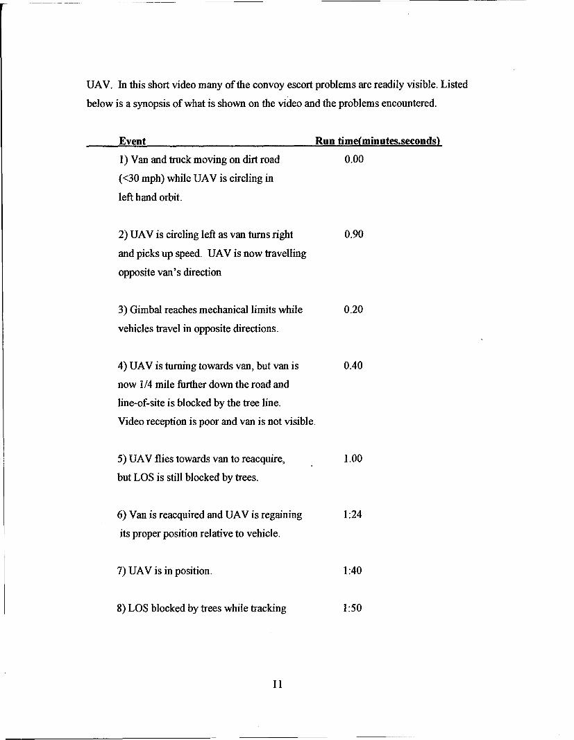
UAV. In this short video many of the convoy escort problems are readily visible. Listed
below is a synopsis of what is shown on the video and the problems encountered.
Event Run time(minutes.seconds)
1) Van and truck moving on dirt road 0.00
(<30 mph) while UAV is circling in
left hand orbit.
2) UAV is circling left as van turns right 0.90
and picks up speed. UAV is now travelling
opposite van's direction
3) Gimbal reaches mechanical limits while 0.20
vehicles travel in opposite directions.
4) UAV is turning towards van, but van is 0.40
now 1/4 mile further down the road and
line-of-site is blocked by the tree line.
Video reception is poor and van is not visible.
5) UAV flies towards van to reacquire, 1.00
but LOS is still blocked by trees.
6) Van is reacquired and UAV is regaining 1:24
its proper position relative to vehicle.
7) UAV is in position. 1:40
8) LOS blocked by trees while tracking 1:50
11
It is interesting to note that a few seconds of bad planning on the part of the UAV
can result in a large separation distance between the UAV and the convoy vehicle.
It can take a single UAV up to 1 minute or more to recover from these seemingly
minor mistakes.
5 Pixel-Based Tracking of Moving targets in Live Video
Pixel-based tracking of moving targets from the UAV's live video is a necessary
capability for tracking suspicious vehicles in the convoy escort mission. The Bat UAV
has not demonstrated this capability yet and MLB has begun investigating
hardware/software solutions to enable this functionality. OCTEC Ltd. is a company in
England that manufactures a single board video processor that can track designated
regions in a video image. MLB contacted OCTEC and they agreed to analyze recorded
video from a Bat UAV to see if tracking of moving targets would be feasible. Small
UAVs like the Bat are more susceptible to turbulence because of their low wing loading
(< 3 lb/ft^2) and this can create unwanted motion in the video that the gimbal system is
too slow to correct for. OCTEC took a sample of Bat video and successfully
demonstrated tracking of moving targets in spite of the jitteriness. An example of the
processed video can be see on our web site at:
http://www.spvplanes.com/OCTEC.mpg
MLB plans to integrate the OCTEC hardware into the Bat UAV in phase 2 of this work.
6 Convoy Escort Strategies and Simulation Results
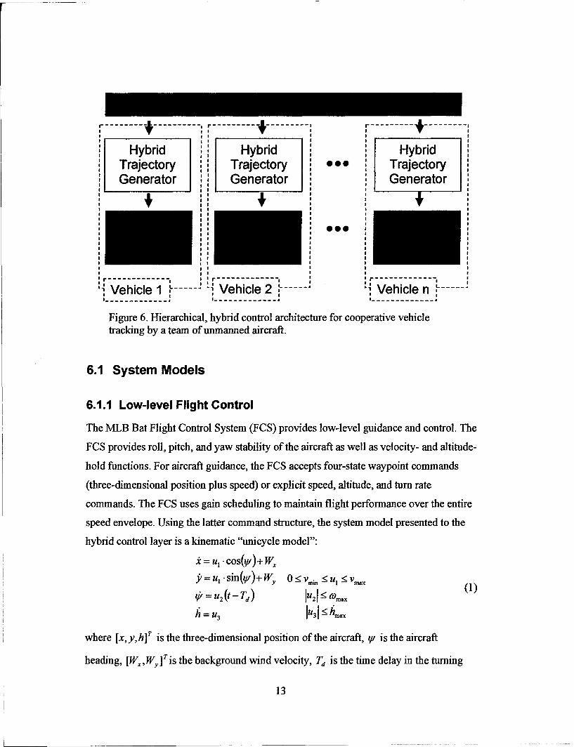
Cooperative control is realized through a hierarchical, hybrid control architecture. The
control system is separated into three layers (Fig. 6): the low level autopilot on each
individual vehicle, a hybrid controller on each vehicle that generates command inputs for
the low-level controller, and a team coordinator that assigns every vehicle to a particular
task or mode. Details of each layer follow.
12
Hybrid Hybrid HybridTrajectory Trajectory TrajectoryGenerator Generator GeneratorI II I
r i I r - ,
SVehicle 1 ---- -... 4 Vehicle 2 1 .... Vehicle n, -L.....-
I . . . . . . . . II *I II 7 • . . . I . . . . . .
-------- I ------ --------
Figure 6. Hierarchical, hybrid control architecture for cooperative vehicletracking by a team of unmanned aircraft.
6.1 System Models
6.1.1 Low-level Flight Control
The NEB Bat Flight Control System (FCS) provides low-level guidance and control. The
FCS provides roll, pitch, and yaw stability of the aircraft as well as velocity- and altitude-
hold functions. For aircraft guidance, the FCS accepts four-state waypoint commands
(three-dimensional position plus speed) or explicit speed, altitude, and turn rate
commands. The FCS uses gain scheduling to maintain flight performance over the entire
speed envelope. Using the latter command structure, the system model presented to the"hybrid control layer is a kinematic "unicycle model":
=ul * cos(v,) + W,jp= u, -sin (y/)+ Wy<vi <5 <_mU
I:! V i IIV.
Vý =U2 (t -T) 1u21- maox
where [x,y,h]a is the three-dimensional position of the aircraft, y. is the aircraft
heading, p dry pis the background wind velocity, Ta is the time delay in the turning
13
rate command that accounts for the roll dynamics of the aircraft, and IU ,u 2 ,u3 ] are the
commanded speed, turning rate, and climb rate, respectively. For this work the climb rate
command is given by simple proportional feedback u3 = -kh (h - hd,, ) where hdes is the
task-specific desired height.
6.1.2 Gimbaled Camera Sensing
The MLB Bat UAV provides a gimbaled camera sensor that is used for all target
tracking. It is assumed here that the gimbaled unit can sweep through its range of motion
with sufficient speed. Therefore the coverage region of the unit is modeled as a single
camera with a field of view defined by gimbal limits. Given UAV altitude h above the
ground and gimbal field of view 0, the sensor traces out a circle of radius rd = h tan(O)
below the UAV. Thus, objects are considered detected if they come within the distance rd
of any UAV.
6.1.3 Terrain Line of Sight Restrictions
In order to consider the effects of terrain line of sight restrictions without the need to
employ complicated ray-tracing algorithms, certain circular regions E, of the
environment are defined as "non-viewable". The motion of the ground vehicles and
aircraft is not impeded by these regions; however, no UAV can detect or sense a target in
these regions.
6.2 Team Coordination Layer
The team coordinator is responsible for assigning each UAV in the group to one of the
modes in the hybrid controller. Current modes include: Loiter, Search, Follow,
SupportFollow, Protect, and Support Protect. The Follow mode is applied to UAVs that
are assigned to track a ground vehicle that is adversarial or unclassified. The Protect
mode refers to UAVs assigned to track "friendly" ground vehicles, i.e. perform convoy
protection. The coordinator has access to all sensor information and can communicate to
every UAV (i.e. the coordination layer is a centralized supervisor). At specified intervals
the coordinator assigns all UAVs based on the current state of the global world model.
14
This model includes the position of all sensed targets, the states of each UAV, and the
area of interest. The coordinator makes assignments in the following order:
"* Each target object is Followed or Protected by one UAV"* Each UAV in Follow/Protect mode is Supported by one UAV"* Remaining UAVs are assigned to Search.
6.2.1 Follow, Protect, and Support Assignment
The team coordinator's first step is to assign at least one UAV to Protect or Follow each
target by using binary integer programming to minimize
ED# .x# (2)i=1 j=I
subject to
n m
Vj, _x, =1 Vi,Ex,, <-1 m _n or (3)ri1 j=l
n M
<_, Ex V, Ex. = I n <m (4)i=1 j=]
where m is the number of targets, n is the number of UAVs, t. is an estimate of the time
needed by UAVi to intercept targetj, and x. is an assignment variable that is equal to 1 if
UAVi is assigned to targetj and zero otherwise. In the current version of the team
coordinator, friendly and adversarial/unclassified ground vehicles are treated equally in
the assignment process. Priority can be given to one set over the other by performing the
assignment task twice, once for the higher priority group and then once for the other
group. If the friendly and unclassified targets are treated equally, UAVs in the Follow or
Support-Follow modes are switched to the Protect or Support Protect modes if an
unclassified target is later classified as friendly (and in need of tracking).
After the coordinator assigns UAVs to Follow/Protect each target, the remaining UAVs
are assigned to Support the UAVs in Follow/Protect mode using the same procedure
described above.
15
6.2.2 Search Assignment
After the Follow, Protect, and Support assignment step, all remaining UAVs are assigned
to the search mode. The team coordinator assigns each remaining UAV to a different
region within the total area of interest. The supervisors onboard the UAVs translate the
assigned regions into waypoints in order to generate lawnmnower search patterns.
The team coordinator breaks the total area of interest into equally sized regions. The
number of regions equals the number of UAVs in the search mode. Using the same
integer programming procedure described above, the coordinator assigns UAVs to
regions based on the distance between the UAV and the center of the regions.
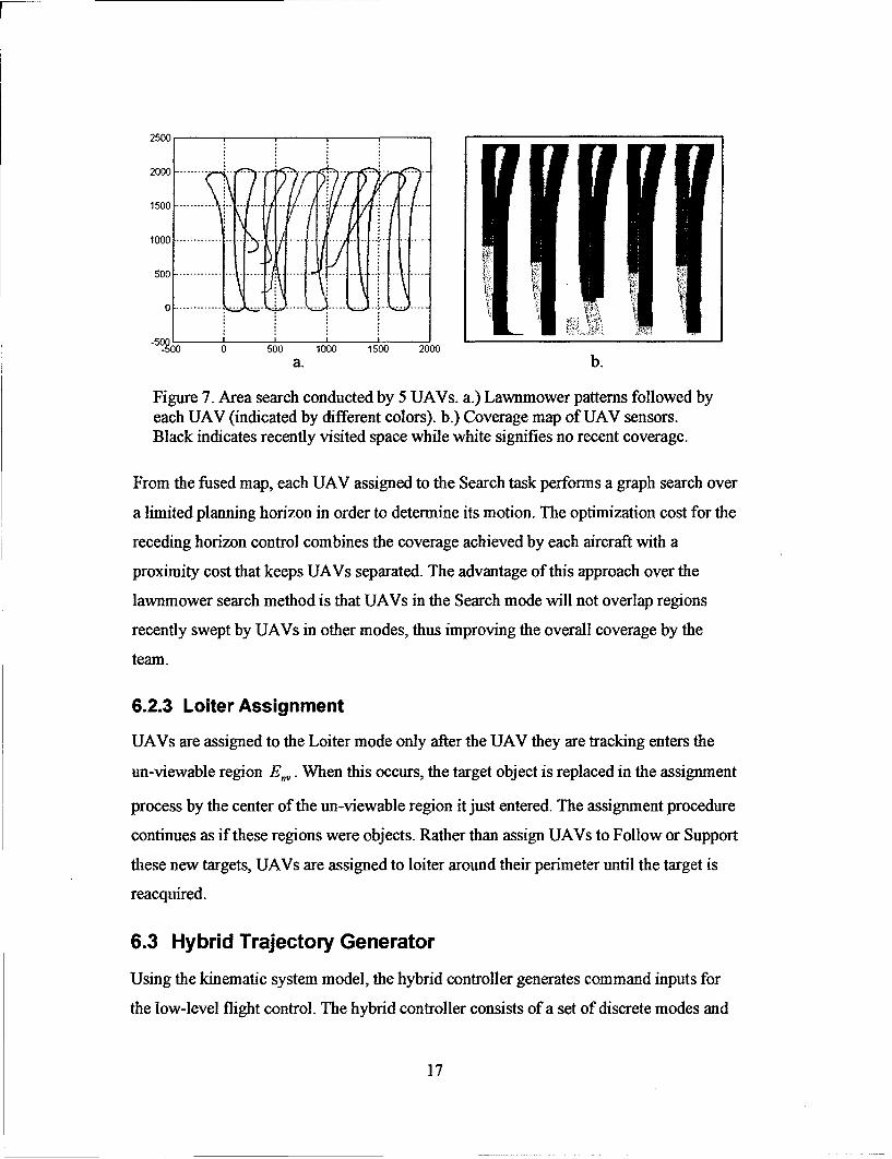
An alternative approach is based on a search map that is used to fuse the sensor coverage
of each UAV. The total search area is discretized into a set of rectangular regions. Each
region is assigned a single value to represent coverage. In the current scheme, coverage is
represented by the time since the most recent visit. This variable approximates the
accuracy of any information gleaned from that region during the previous visit. After this
value increases past a minimum threshold the region is considered uncovered. The
coverage value is reset to zero whenever a certain percentage of any UAV's individual
sensor footprint enters the region. Fig. 7b shows the search map for a search task
performed by 5 UAVs. In this map, black indicates recent coverage and white indicates
no coverage.
16
2500
2000 ......... .. .. ..
1500......- ----- -
10 0 0 ------- ---- -- ... .. . ..
500 ............. .. - -- --. ..... .- .- ..... - -- 4. .
5 0 0 500 1000 1500 2000
a. b.
Figure 7. Area search conducted by 5 UAVs. a.) Lawnmower patterns followed byeach UAV (indicated by different colors). b.) Coverage map of UAV sensors.Black indicates recently visited space while white signifies no recent coverage.
From the fused map, each UAV assigned to the Search task performs a graph search over
a limited planning horizon in order to determine its motion. The optimization cost for the
receding horizon control combines the coverage achieved by each aircraft with a
proximity cost that keeps UAVs separated. The advantage of this approach over the
lawnmower search method is that UAVs in the Search mode will not overlap regions
recently swept by UAVs in other modes, thus improving the overall coverage by the
team.
6.2.3 Loiter Assignment
UAVs are assigned to the Loiter mode only after the UAV they are tracking enters the
un-viewable region E,,. When this occurs, the target object is replaced in the assignment
process by the center of the un-viewable region it just entered. The assignment procedure
continues as if these regions were objects. Rather than assign UAVs to Follow or Support
these new targets, UAVs are assigned to loiter around their perimeter until the target is
reacquired.
6.3 Hybrid Trajectory Generator
Using the kinematic system model, the hybrid controller generates command inputs for
the low-level flight control. The hybrid controller consists of a set of discrete modes and
17
a set of (possibly) different continuous controllers for each mode. In its current
configuration the control has the modes described in Section 6.2. The switching logic
between modes is controlled by an onboard supervisor and by commands from the
higher-level team coordinator. Commands from the team coordinator take precedence
over all onboard supervisor commands.
6.3.1 Loiter and Follow Controllers
The Loiter, Follow, and Support controllers are all based on a Lyapunov vector field
approach in which the unmanned vehicle circles about a designated point [x1 ,,y, IT that
may be stationary or moving. The control maneuvers occur at a commanded altitude hd,,e
(which may vary for each mode) with a commanded nominal speed ul = V0 and radius
R0. The motion is controlled using a Lypanov vector field to calculate the desired planar
velocity [.d,Jd IT and then using proportional feedback from the heading angle error to
command the turning rate. The Lyapunov function V(x,y)= (r2 - d.2 ), where
r = ý(x - x1 )2 + (y Y1 )2 = y, + Ay2 is the radial distance of the UAV from the loiter
position, leads to the guidance vector field
r.2 222V 2 2-+r
fAx,Y) = 2 2y•52.)
1_ r + rd rr + rd
The desired heading Vld is calculated from Equation (5) and the heading angle error is
fed back to the turn rate command
Yd= arctan(!i-1, (6)( Xd)
U2 =-K.(u-Yld). (7)
Stand-off tracking of a moving ground vehicle is accomplished using the Lyapunov
vector field approach in the frame of reference attached to a moving point, i.e. relative to
the position of the ground vehicle. If the velocity of the moving target is known or
estimated, the controller can be modified to ensure that the UAV remains outside of the
18
stand-off radius. A new command is calculated by adding the target's velocity to the
Lyapunov guidance vector. The scaling of the guidance vector is calculated in order to
maintain the desired UAV speed. Given the guidance direction vector f = [L.,L. IT ,the
target velocity [TX,TY T, and a scale factor a, the velocity of the UAV in global
coordinates is:
V = [V_ = [TT + c-*L_] (8)
Taking the norm of Equation (8) and setting it to the desired speed Vo, leads to the
following expression for the scale factor:
a 2(+LV9+ca.2.(L.T+L .TY) (T+ (T2 +r:)- Vo2 = 0(9
Equation (9) is solved for a, which is substituted back into Equation (8) to determine the
desired velocity and heading.
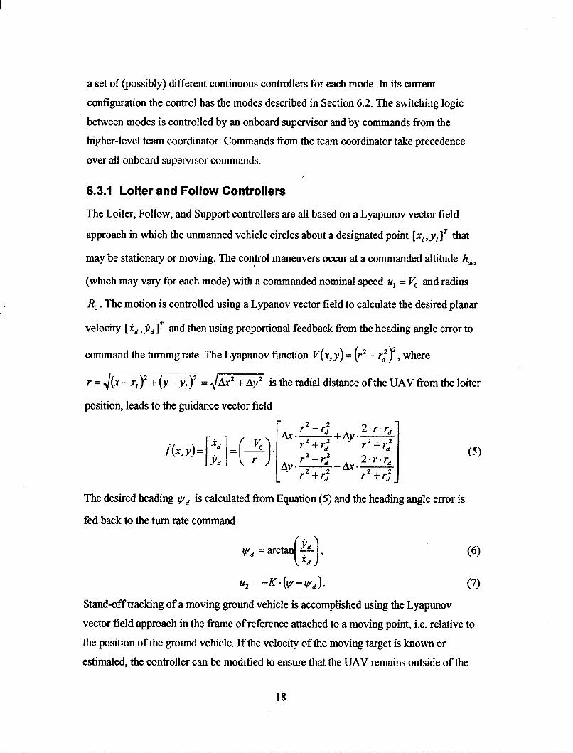
Fig. 8 shows an example of UAV behavior in the Loiter mode. The UAV begins at
position (800, 800) meters and is commanded to loiter around the origin with a speed of
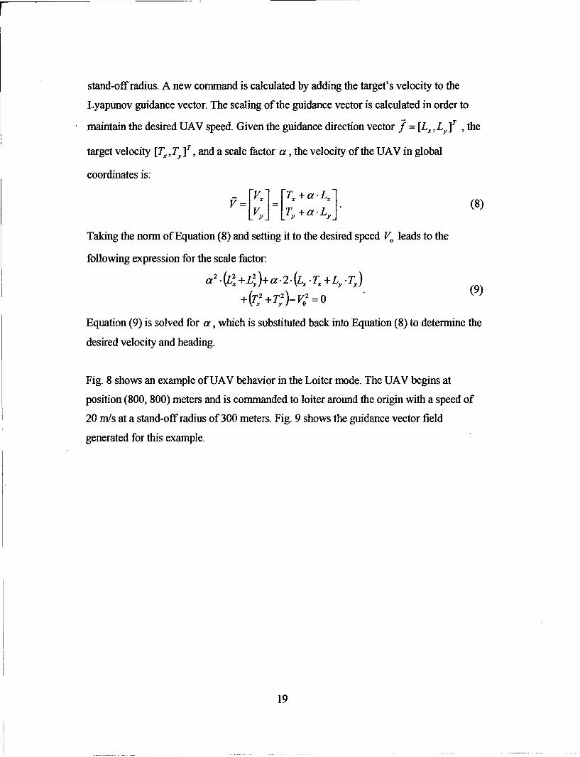
20 m/s at a stand-off radius of 300 meters. Fig. 9 shows the guidance vector field
generated for this example.
19
400 ........ ,. . .... -- ------ .. -- -------- ---------- ---------- _ -------.
200 --- - ' - Standoff - - - --- - - ------------ -
-200
-200 0 200 400 600 800 1000
Figure 8. Example Loiter maneuver. The UAV begins at (800,800) meters andis commanded to loiter around the origin with a radius of 300 meters and aspeed of 20 m/s.
800 P P k. . . .
600pp
400 P P P ,'."
200 PP P
? PA',, ~444A'A4S IýW tN
rn 4 4 kk
2200
t .. * rVIf # 440 4 4 4 4 A A A &1 k k W W .K
Aýoo -200 0 200 400 600 800 1000
Figure 9. Lyapunov vector field loiter maneuver around theorigin with a radius of 300 meters (dashed line).
An example Follow task when the target velocity is unknown is illustrated in Fig. 10 and
Fig. 11. The UAV is commanded to follow a ground vehicle moving with a velocity of
(0, 10) m/s. The UAV attempts to maintain a 300 meter stand-off distance while traveling
20
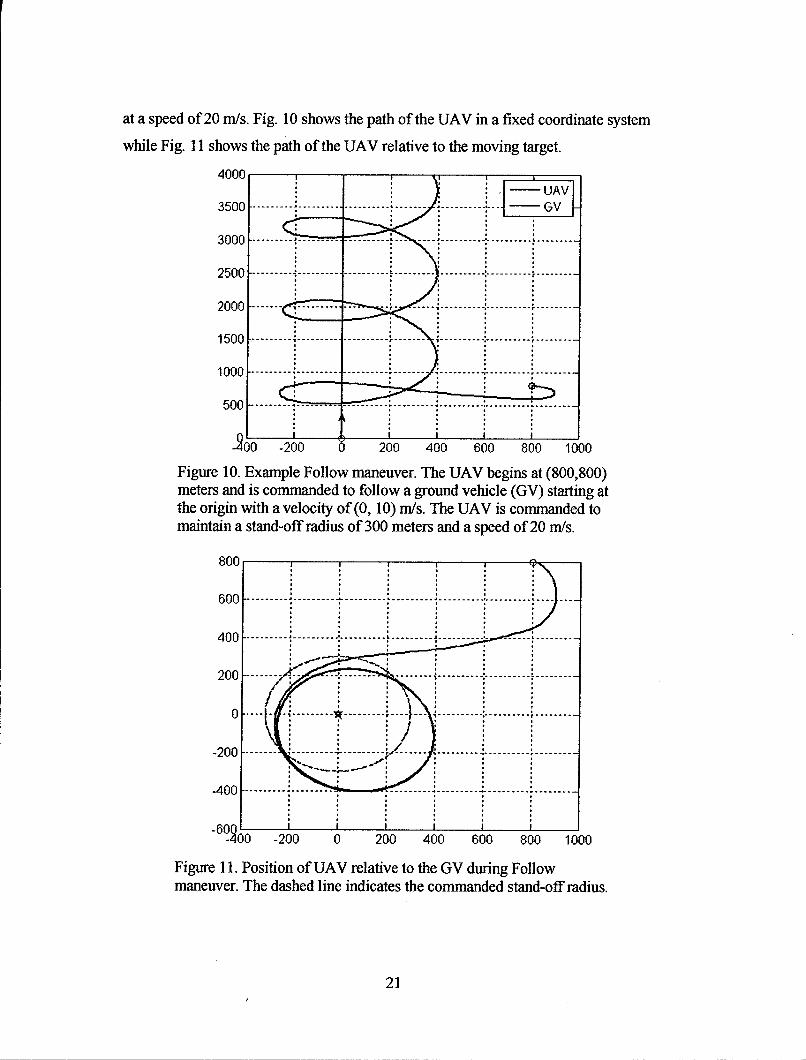
at a speed of 20 m/s. Fig. 10 shows the path of the UAV in a fixed coordinate system
while Fig. 11 shows the path of the UAV relative to the moving target.
4000
3500- -----------------------------
3000---------- ------------
500--------------------------------
5 0 0 ....... . ---------------------------------.. .•.. ... .. . ... ..
100 -200 0 200 400 600 800 1000
Figure 10. Example Follow maneuver. The UAV begins at (800,800)meters and is commanded to follow a ground vehicle (GV) starting atthe origin with a velocity of(0, 10) m/s. The UAV is commanded tomaintain a stand-off radius of 300 meters and a speed of 20 m/s.
800 2 4 600 --- --- --- --- --- --.. ..-- ---I.. ..-- --- ---------- --.........---- -- ----..200 -- -- -- -- --- --- ... .. ....... i... .. . . . . . .
Fiur .... Poito ofUVrlv to ..the.GV dur.....in Follow..
'40 -200 0 200 400 600 800 1000
Figure 1 1. Position of UAV relative to the GV during Follow
maneuver. The dashed line indicates the commanded stand-off radius.
21
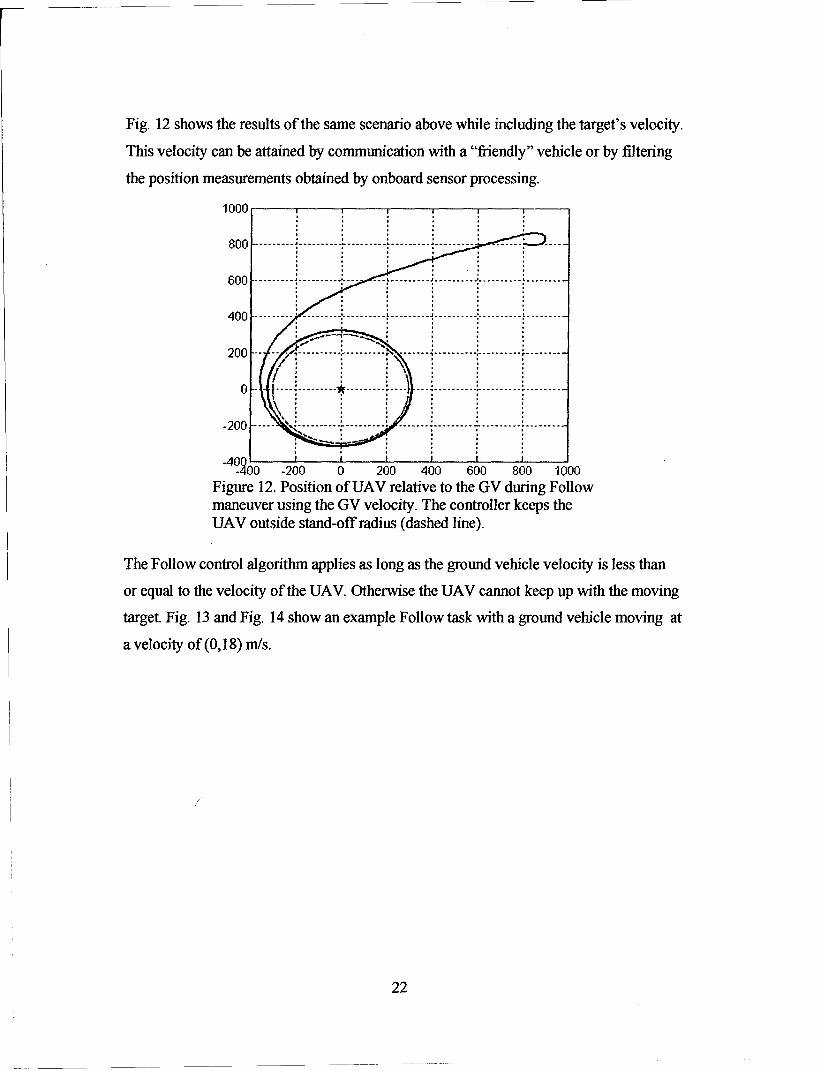
Fig. 12 shows the results of the same scenario above while including the target's velocity.
This velocity can be attained by communication with a "friendly" vehicle or by filtering
the position measurements obtained by onboard sensor processing.
1000
200• 0 20 00 60,0,10
8400 ------- ------ ----------- ------ ------ 800 -100
Figure 12. Position of UAV relative to the GV during Followmaneuver using the GV velocity. The controller keeps theUAV outside stand-off radius (dashed line).
The Follow control algorithm applies as long as the ground vehicle velocity is less than
or equal to the velocity of the UAV. Otherwise the UAV cannot keep up with the moving
target. Fig. 13 and Fig. 14 show an example Follow task with a ground vehicle moving at
a velocity of (0,18) m/s.
22

8000 r -UAV
7000- ..-.. ..... G.................... ...... I .... G V
6000 --- -- - - -- -- - - -- -- - -- - -- - - -- -- - - --
4000 --------- ------ --------
2 0 0 0 ----------- -; ------.. .... ..... -- .. .. . --.... .....- -I . . . .---........ .
Iw1 -- ----- -- --.......... ;................ ......
00 2W 4W 6 800 1000
Figure 13. Example Follow maneuver. The UAV begins at (800,800)meters and is commanded to follow a ground vehicle (GV) starting atthe origin with a velocity of (0, 18) m/s. The UAV is commanded tomaintain a stand-off radius of 300 meters and a speed of 20 mrs.
1000
400~~~~~~~~ ~ ~ ~ -------.----------.------------......... ........
-200 --- --... . ... .. .... . .. ...------- .-.. .........-
& -200 0 200 400 600 800 1000
Figure 14. Position of UAV relative to the GV during Followmaneuver. The dashed line indicates the commanded stand-off radius.
6.3.2 Support Mode: Coordinated Stand-off Tracking by Two Vehicles
When a team of vehicles are assigned to follow a single target, i.e. one UAV is assigned
to Support another, coordination between UAVs is necessary to avoid collisions and to
23

maximize sensor coverage of vehicle motion. Team tracking can improve sensor
coverage when the target vehicle is uncooperative, or is highly agile, such that estimates
of its position and velocity are poor. The idea is to distribute UAVs in the group
uniformly in phase on the tracking loiter circle, so that unpredicted changes in vehicle
motion can be observed and followed at least by the UAV in the most advantageous
position.
Phase coordination is produced by a second Lyapunov guidance law, which adjusts the
speed of the vehicles (within limits) to maintain desired relative phase on the loiter circle
provided by the first Lyapunov law (Equation 4). The resulting speed commands are
then processed through the correction algorithm (Equation 7) to maintain the desired
standoff distance to the moving target.
' Target " Loiter
Figure 15. Phase angles for a team of UAVs tracking a single target.
Fig. 15 shows a two-UAV tracking team, with corresponding phase angles O0 and
02 defined relative to the instantaneous tracking loiter circle. The phasing Lyapunov
function is
VP = (02-_-_OD) 2 (10)
whose rate of change is
d V= 2(0 2 -0 2 -OD)(02 -Od). (11)dt
Choosing the angular speed commands
]= k(0 2 - 01 - OD )+ VO/ RO (12)
02=-k(02 - 0 -OD)+Vo/Ro (13)
24

results in
d- = -4kVp, (14)dt
which produces exponential convergence of Vp to zero, i.e. convergence of the relative
angle 02 - 0 to the desired phase offset OD. The corresponding speed commands to the
flight control subsystems are then
u,1 ] = k(02 -0-OD)RO + VO
u1, 2 = -k(0 2 -01 -OD)R + " (15)
In the case of a two-UAV team, we choose the offset OD to be an odd multiple of z
radians. It is interesting to note that the multiple of Tr chosen determines which UAV is
phased ahead of the other. For example, choosing the odd multiple of z closest to the
initial angular offset of the UAVs preserves their initial ordering in phase on the loiter
circle. Choosing a different multiple of ir causes one UAV to overtake the other,
switching the phase order before settling to the desired 180 degree relative offset.
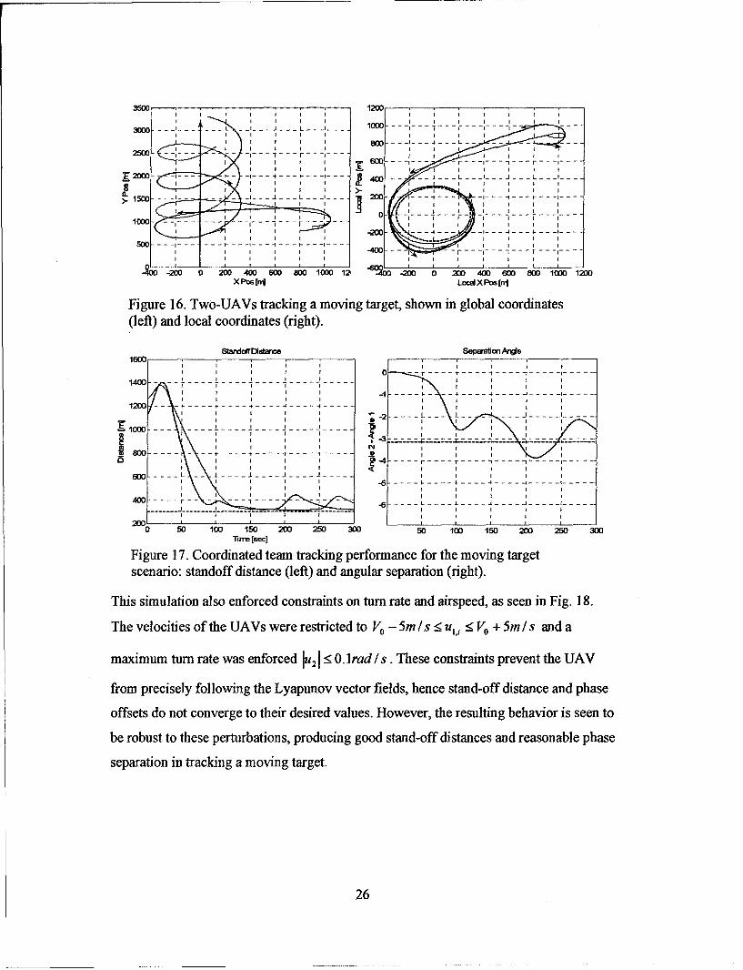
Fig. 16 shows the results of the overall control scheme, where two UAVs act in a team to
follow a moving target, maintaining a desired standoff distance as well as a desired loiter
circle phasing. The left plot shows UAV paths (blue and green) in global coordinates,
where the vehicle to be tracked followed the red line, moving with constant velocity
along the Y-direction. The right plot shows the view of this same motion in a coordinate
system attached to the tracked vehicle ('x'). Here it is clear that the UAVs are attracted to
a loiter circle about the GV, and maintain the desired standoff distance (dashed circle).
Fig. 17 shows the standoff distance and phase angle separation of the vehicles versus
time.
25
3501200
SI I I II I I I
3D....lo - --- - - L l-.. .
4 -I -I I -
I IS M _ LII I I S I - I
~~~~~-2 0 -.. . -- -. . . . . , , - - - -- - - - -- ,- - - -. 5001 -- --
Figure 16. Two-UAVs tracking a moving target, shown in global coordinates(left) and local coordinates (right).
IWOt~ Separ~onArde
.16_ _, _ _._ , _ ,
1400 -
SI I I I -I I I I
I I -I I I- - - - - -
- -00-- -- ----- - ---- - -----
II I I I II III I I I
-r -- -.. .- -- -... . .'o ...
-4 - - - - - r - - - - --
1600 - - , , L -
-- ------- . 1 I-.
1400 30 , i• 1ý ýý ýt 3D/
I I I I I I
I I I I II I I
I I I I I "4IT "
I I II I I I I I
II I I I II I
00 50 100 150 200 20 300 100la 150 200 20 300
Figure 17. Coordinated team tracking performance for the moving targetscenario: standoff distance (left) and angular separation (right).
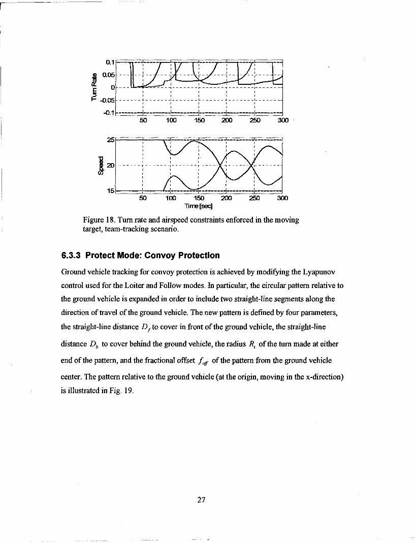
This simulation also enforced constraints on turn rate and airspeed, as seen in Fig. 18.
The velocities of the UAVs were restricted to Vo, - 5m/s < u,• <_ Vo, + 5mls and a
maximum turn rate was enforced[ :19 -0. lrad /s. These constraints prevent the UAV
from precisely following the Lyapunov vector fields, hence stand-off distance and phase
offsets do not converge to their desired values. However, the resulting behavior is seen to
be robust to these perturbations, producing good stand-off distances and reasonable phase
separation in tracking a moving target.
26
0.05 -- ---- ---
0 _ _ - - - - - - - I - - - - -t - - - - - - - -
•0.0.5 - -•-
J - - - L - - -I - - - - II- - -
F F20 --- ---20.5
- ---
F--SI F .
50 100 150 200 250 300F F-F F
150 10'5 0 5 0
"Tirne[seq]
Figure 18. Turn rate and airspeed constraints enforced in the movingtarget, team-tracking scenario.
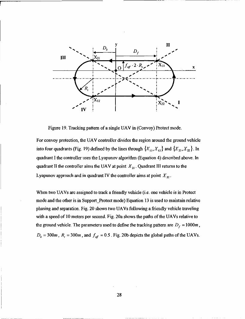
6.3.3 Protect Mode: Convoy Protection
Ground vehicle tracking for convoy protection is achieved by modifying the Lyapunov
control used for the Loiter and Follow modes. In particular, the circular pattern relative to
the ground vehicle is expanded in order to include two straight-line segments along the
direction of travel of the ground vehicle. The new pattern is defined by four parameters,
the straight-line distance Df to cover in front of the ground vehicle, the straight-line
distance Db to cover behind the ground vehicle, the radius R, of the turn made at either
end of the pattern, and the fractional offset fof of the pattern from the ground vehicle
center. The pattern relative to the ground vehicle (at the origin, moving in the x-direction)
is illustrated in Fig. 19.
27
y IIDb - -
4-7,II - s ""S........... ,_ .......... ............ I.... % ................. ......... ............
!'X12s 2•.
-X22% %
Figure 19. Tracking pattern of a single UAV in (Convoy) Protect mode.
For convoy protection, the UAV controller divides the region around the ground vehicle
into four quadrants (Fig. 19) defined by the lines through {X, X1,2 } and {X21 , X22 }. In
quadrant I the controller uses the Lyapunov algorithm (Equation 4) described above. In
quadrant II the controller aims the UAV at point X 21. Quadrant 1II returns to the
Lyapunov approach and in quadrant IV the controller aims at point X 22 .
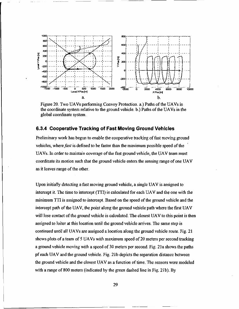
When two UAVs are assigned to track a friendly vehicle (i.e. one vehicle is in Protect
mode and the other is in SupportProtect mode) Equation 13 is used to maintain relative
phasing and separation. Fig. 20 shows two UAVs following a friendly vehicle traveling
with a speed of 10 meters per second. Fig. 20a shows the paths of the UAVs relative to
the ground vehicle. The parameters used to define the tracking pattern are Df = I000m,
Db = 300m, R, = 300m, and f= 0.5. Fig. 20b depicts the global paths of the UAVs.
28
J.•6 0 - -- - -. . . -- -_ . . . --- -I --...
400 - .4oc ~~~~40 - - - --------------• .. ;.. .
-21)0->--,--
.. - - - - n n
-4 ...--- 4 - - .. - - -. . - -- -" -..'. . -- o -----~ I' -" I I- -f -I . .-' --
-600 -- -2O---- - -- I I I
0 50 1000 1500 2000
-10Oc -SM 0 scni9 is z 0 2-D3D 400 SWO 80M 12000Lo:W X Ps [rni XPos f[r
a. b.
Figure 20. Two UAVs performing Convoy Protection. a.) Paths of the UAVs inthe coordinate system relative to the ground vehicle. b.) Paths of the UAVs in theglobal coordinate system.
6.3.4 Cooperative Tracking of Fast Moving Ground Vehicles
Preliminary work has begun to enable the cooperative tracking of fast moving ground
vehicles, wherefast is defined to be faster than the maximum possible speed of the
UAVs. In order to maintain coverage of the fast ground vehicle, the UAV team must
coordinate its motion such that the ground vehicle enters the sensing range of one UAV
as it leaves range of the other.
Upon initially detecting a fast moving ground vehicle, a single UAV is assigned to
intercept it. The time to intercept (TTI) is calculated for each UAV and the one with the
minimum TTI is assigned to intercept. Based on the speed of the ground vehicle and the
intercept path of the UAV, the point along the ground vehicle path where the first UAV
will lose contact of the ground vehicle is calculated. The closest UAV to this point is then
assigned to loiter at this location until the ground vehicle arrives. The same step is
continued until all UAVs are assigned a location along the ground vehicle route. Fig. 21
shows plots of a team of 5 UAVs with maximum speed of 20 meters per second tracking
a ground vehicle moving with a speed of 30 meters per second. Fig. 21a shows the paths
pf each UAV and the ground vehicle. Fig. 21b depicts the separation distance between
the ground vehicle and the closest UAV as a function of time. The sensors were modeled
with a range of 800 meters (indicated by the green dashed line in Fig. 21b). By
29
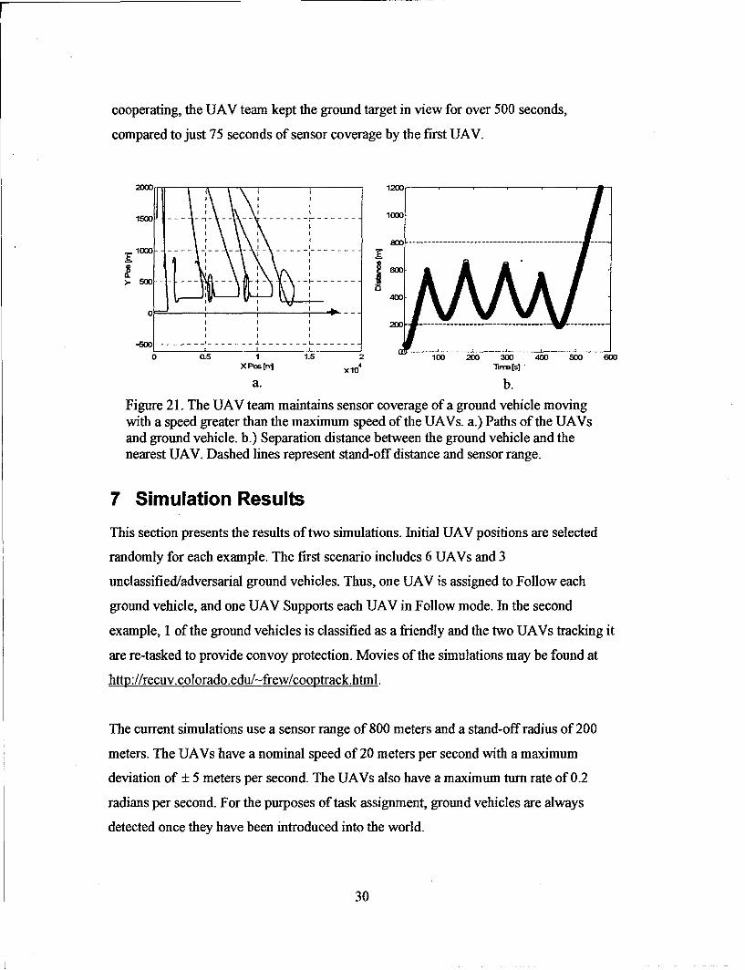
cooperating, the UAV team kept the ground target in view for over 500 seconds,
compared to just 75 seconds of sensor coverage by the first UAV.
I I
1500 .I 1000
15oo -- - -- - -- -- -- - -- - -- - --- --- --
S l o o o - -- - --- - - - - -
W- 50-- ------------------- L-! I ------- -...o a5 1.5 100o 2Wo 3o 400 6oo 6Wo
xPs[j xio Tnrm[s]"
a. b.
Figure 21. The UAV team maintains sensor coverage of a ground vehicle movingwith a speed greater than the maximum speed of the UAVs. a.) Paths of the UAVsand ground vehicle. b.) Separation distance between the ground vehicle and thenearest UAV. Dashed lines represent stand-off distance and sensor range.
7 Simulation Results
This section presents the results of two simulations. Initial UAV positions are selected
randomly for each example. The first scenario includes 6 UAVs and 3
unclassified/adversarial ground vehicles. Thus, one UAV is assigned to Follow each
ground vehicle, and one UAV Supports each UAV in Follow mode. In the second
example, 1 of the ground vehicles is classified as a friendly and the two UAVs tracking it
are re-tasked to provide convoy protection. Movies of the simulations may be found at
http://recuv.colorado.edu/-frew/cooptrack.html.
The current simulations use a sensor range of 800 meters and a stand-off radius of 200
meters. The UAVs have a nominal speed of 20 meters per second with a maximum
deviation of ± 5 meters per second. The UAVs also have a maximum turn rate of 0.2
radians per second. For the purposes of task assignment, ground vehicles are always
detected once they have been introduced into the world.
30

The environment used for the simulations presented in this section is the Table Mountain
Radio Quiet Zone in Boulder, CO. This area serves as a test range for the CU Boulder
AUGNet project and other UAV projects. The flight range is approximately 3600 meters
by 4200 meters. In the simulations presented below the vehicles follow the roads on the
Table Mountain facility. The UAVs do not make use of knowledge of the roads in their
planning.
7.1 Scenario 1: Three Unclassified Ground Vehicles
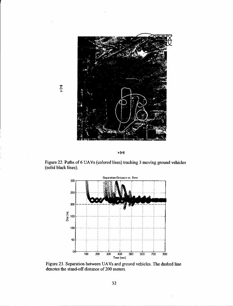
Fig. 22 depicts the paths of the 6 UAVs and the 3 ground vehicles in scenario 1. THe
colored lines represent the UAVs while the solid black lines denote the moving ground
vehicles. Each UAV begins in the search mode and is eventually assigned to track one of
the three ground vehicle. Fig. 23 shows a plot of the separation distance between each
ground vehicle and the two UAVs assigned to track it. After converging to the specified
loiter circles, the UAVs maintain a stand-off distance between 200 - 250 meters. The
commanded stand-off distance is violated (e.g. at approximately 450 seconds) only when
the ground vehicle changes direction. Even then, the UAV responds quickly and moves
away from the target.
31
x [rr
Figure 22. Paths of 6 UAVs (colored lines) tracking 3 moving ground vehicles(solid black lines).
Separation Distance vs. Time
300
250 . ...........
200 •
TS1 5 0 .......... I.......... ................................. .. ....................... . . . .
100 . .. ..................... .......... ..................... .......... .....................
5 0 ...... . . . . . . . . .................... .............. ....... .....................
100 200 300 400 500 600 700 800Time Isec]
Figure 23. Separation between UAVs and ground vehicles. The dashed linedenotes the stand-off distance of 200 meters.
32

Fig. 24 - Fig. 26 show the state of the world at times 51 sec, 226 sec, and 251 sec, just
after each ground vehicle is detected. In Fig. 24, each UAV is searching a different region
of the environment when the first vehicle is detected. UAV1 is closest to the target and is
assigned to Follow. UAV4 is the next closest and is assigned to Support UAV1. The
remaining UAVs are assigned new search regions. Fig. 25 depicts the state of the team at
226 seconds when the second ground vehicle is detected. UAV6 is assigned to Follow the
second ground vehicle and because UAV4 is close to the second ground vehicle it is re-
assigned to Support UAV6. UAV5 is then assigned to support UAVI, taking the place of
UAV4. Fig. 26 shows a sequence of steps during this re-assignment process. Finally, Fig.
27 shows the detection of the third ground vehicle. UAV2 and UAV3 are closest to the
target and assigned to Follow and Support respectively.
Figure 24. The first ground vehicle enters the region of interest at time 51 seconds.
33

Fi-ure 25. The second UAV is detected at time 226 seconds.
t=225.OO t=245 00
t=265.OO t--285.00
Figure 26. Sequence of plots show (re)assignment of UAVs after thesecond ground vehicle is detected.
34

Figure 27. The final ground vehicle appears at time 251 seconds.
7.2 Scenario 2: Two Unclassified, One Friendly Ground Vehicle
In this scenario six UAVs track three ground vehicles. Unlike Scenario 1, the third
ground vehicle is classified as a friendly vehicle so UAV2 and UAV3 enter Protect and
Support-Protect modes instead of Follow and Support Follow. Fig. 28 shows the paths of
each UAV and ground vehicle throughout the simulation. Fig. 29 shows the paths of
UAV2 and UAV3 as well as their sensor trace. Here, a sensor radius of 200 meters is
used in order to simulate the field of view of the gimbaled camera on the MLB Bat,
compared to the 800 meter sensor radius used in Section 4.2.4 to describe the full range
of the gimbal unit. Fig. 30 shows the UAVs and ground vehicle at several different times
throughout the scenario. In every case the sensor coverage extends beyond the current
location of the ground vehicle. This illustrates the coverage of the environment around
the UAV in order to provide significant advance warning for possible threats.
35
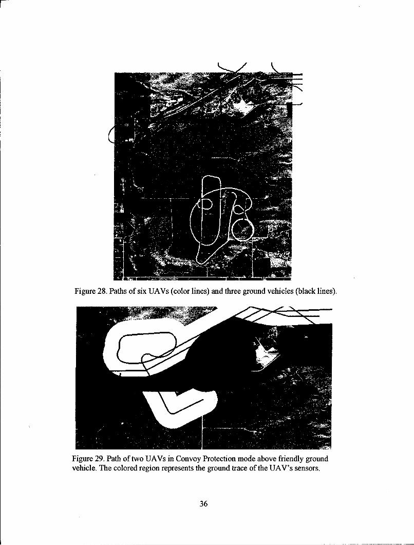
Figure 28. Paths of six UAVs (color lines) and three ground vehicles (black lines).
Figure 29. Path of two UAVs in Convoy Protection mode above friendly groundvehicle. The colored region represents the ground trace of the UAV's sensors.
36
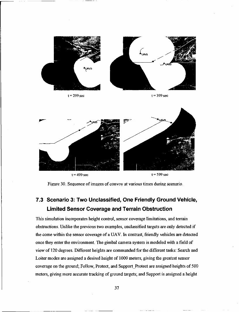
t =299 sec t 399 sec
t =499 sec t = 599 sec
Figure 30. Sequence of images of convoy at various times during scenario.
7.3 Scenario 3: Two Unclassified, One Friendly Ground Vehicle,
Limited Sensor Coverage and Terrain Obstruction
This simulation incorporates height control, sensor coverage limitations, and terrain
obstructions. Unlike the previous two examples, unclassified targets are only detected if
the come within the sensor coverage of a UAV. In contrast, friendly vehicles are detected
once they enter the environment. The gimbal camera system is modeled with a field of
view of 120 degrees. Different heights are commanded for the different tasks: Search and
Loiter modes are assigned a desired height of 1000 meters, giving the greatest sensor
coverage on the ground; Follow, Protect, and SupportProtect are assigned heights of 500
meters, giving more accurate tracking of ground targets; and Support is assigned a height
37

of 750 meters in order to maintain greater coverage at the expense of worse resolution.
Two un-viewable regions are included that lie on the roads in the simulation
environment. These regions have radii of 350 and 400 meters. Fig. 31 shows the paths of
each ground vehicle and UAV in this simulation. The shaded circles represent regions of
zero sensor visibility.
Figure 31. Paths of six UAVs (color lines) and three ground vehicles
(black lines). The shaded circles represent regions of zero sensor visibility.
Fig. 32 - Fig. 33 depicts the simulation at 61 seconds, 239 seconds, and 272 seconds
when each ground vehicle is first detected. Compared to the previous example, the first
two targets are detected 10 seconds and 13 seconds after they first appear in the
environment. UAV1 and UAV4 are assigned to the first target since they are closest to it
upon detection. Fig. 33a depicts the UAVs when the second target is detected. At this
time UAV1 and UAV4 have descended to their commanded heights in order to track
GV1. The sensor ground coverage is reduced for these UAVs since they have descended
38

from their Search heights. Fig. 33b depicts the environment when the third ground
vehicle, a friendly vehicle, enters the environment and is detected.
Figure 32. UAVs at time 61 seconds when first ground vehicle isdetected. Shaded circles represent regions of no sensor visibilityand unfilled circles denote coverage of UAV sensors.
39
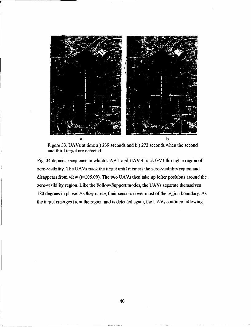
a. b.Figure 33. UAVs at time a.) 239 seconds and b.) 272 seconds when the secondand third target are detected.
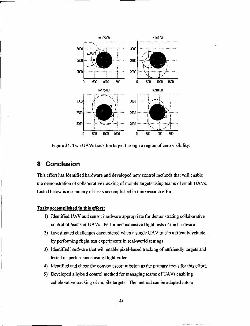
Fig. 34 depicts a sequence in which UAV I and UAV 4 track GVI through a region of
zero-visibility. The UAVs track the target until it enters the zero-visibility region and
disappears from view (t=105.00). The two UAVs then take up loiter positions around the
zero-visibility region. Like the Follow/Support modes, the UAVs separate themselves
180 degrees in phase. As they circle, their sensors cover most of the region boundary. As
the target emerges from the region and is detected again, the UAVs continue following.
40
t=105.00 t=140.00
3000 .... . 3.000 ........
2000 2000 ........ . .......
0 500 1000 1500 0 500 1000 1500
t--175,00 t=210.00
3000 ...... ...... ... .. 3300 .... ... .. .... ...... ....
0 500 1000 1500 0 500 1000 1500
Figure 34. Two UAVs track the target through a region of zero visibility.
8 Conclusion
This effort has identified hardware and developed new control methods that will enable
the demonstration of collaborative tracking of mobile targets using teams of small UAVs.
Listed below is a summary of tasks accomplished in this research effort.
Tasks accomplished in this effort:
1) Identified UAV and sensor hardware appropriate for demonstrating collaborative
control of teams of UAVs. Performed extensive flight tests of the hardware.
2) Investigated challenges encountered when a single UAV tracks a friendly vehicle
by performing flight test experiments in real-world settings.
3) Identified hardware that will enable pixel-based tracking of unfriendly targets and
tested its performance using flight video.
4) Identified and chose the convoy escort mission as the primary focus for this effort.
5) Developed a hybrid control method for managing teams of UAVs enabling
collaborative tracking of mobile targets. The method can be adapted into a
41
decentralized control scheme with the addition of ad-hoc network communication
hardware.
6) Tested the hybrid control scheme in a nonlinear simulation. The simulation
includes the effects of multiple UAVs, friendly and unfriendly vehicles, terrain
obstacles, and sensor motion constraint parameters.
7) Developed methods for coordinated control that provides collision avoidance,
terrain avoidance, terrain obstruction of sensors, and maintains stand-off distance
while tracking.
42
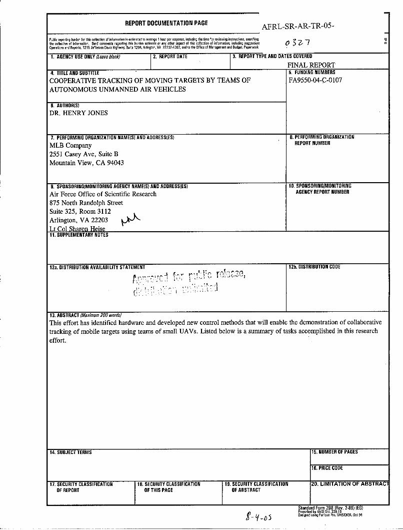
REPORT DOCUMENTATION PAGE AFRL-SR-AR-TR-05-
Public reporting burden for this collection of information is estimated to average I hour per response, including the time for reviewing instructlons, searching Igthe collection of information. Send comments regarding this burden estimate or any other aspect of this collection of information, including suggestion! 0 a -7 mnOperations and Reports, 1215 Jefferson Davis Highway, Suite 1204, Arlington, VA 22202-4302, and to the Office of Management and Budget, Paperwork I
1. AGENCY USE ONLY (Leave blank) 2. REPORT DATE 3. REPORT TYPE AND DATES COVERED
I I FINAL REPORT4. TITLE AND SUBTITLE 5. FUNDING NUMBERS
COOPERATIVE TRACKING OF MOVING TARGETS BY TEAMS OF FA9550-04-C-0107AUTONOMOUS UNMANNED AIR VEHICLES
6. AUTHOR(S)
DR. HENRY JONES
7. PERFORMING ORGANIZATION NAME(S) AND ADDRESS(ES) B. PERFORMING ORGANIZATION
MLB Company REPORT NUMBER
2551 Casey Ave, Suite BMountain View, CA 94043
9. SPONSORINGIMONITORING AGENCY NAME(S) AND ADDRESS(ES) 10. SPONSORINGIMONITORING
Air Force Office of Scientific Research AGENCY REPORT NUMBER
875 North Randolph Street
Suite 325, Room 3112Arlington, VA 22203Lt Col Sharon Heise11. SUPPLEMENTARY NOTES
12a. DISTRIBUTION AVAILABILITY STATEMENT 12b. DISTRIBUTION CODE
13. ABSTRACT (Maximum 200 words)
This effort has identified hardware and developed new control methods that will enable the demonstration of collaborative
tracking of mobile targets using teams of small UAVs. Listed below is a summary of tasks accomplished in this researcheffort.
14. SUBJECT TERMS 15. NUMBER OF PAGES
16. PRICE CODE
17. SECURITY CLASSIFICATION 18. SECURITY CLASSIFICATION 19. SECURITY CLASSIFICATION 20. LIMITATION OF ABSTRACIOF REPORT OF THIS PAGE OF ABSTRACT
Standard Form 298 (Rev. 2-89) (EG)Prescribed by ANSI Std. 239.18Designed using Perform Pro, WHSIDIOR, Oct 94