development of digital wind speed …umpir.ump.edu.my/1286/1/cd_3322.pdfkuliah, dewan, bilik...
TRANSCRIPT

WIRELESS WIND ENERGY DATA TRANSMISSION SYSTEM
AHMAD HAZIQ BIN TARIF
This thesis is submitted as partial fulfillment of the requirements for the award
of the Bachelor of Electrical Engineering (Hons.) (Electronics)
Faculty of Electrical & Electronic
Universiti Malaysia Pahang
MAY 2009

vi
ABSTRACT
Wireless communications represent a rapidly emerging area of growth and
importance for providing ubiquitous access to the network for all type of community.
Nowadays, all community increasingly wants network access for general purpose at
classrooms, meeting rooms, auditoriums, and even the hallways of campus buildings.
Wireless communications can both support the institution mission and provide cost-
effective solutions. Wireless is being adopted for many new applications: to connect
computers, to allow remote monitoring and data transceiver or acquisition, to provide
access control and security, and to provide a solution for environments where wires
may not be the best solution. Wireless technology will become our new life in the
future.
vii
ABSTRAK
Teknologi komunikasi tanpa wayar adalah teknologi yang semakin
berkembang dengan pesat dan penting dalam memberikan kemudahan melayari
internet tanpa kabel kepada semua lapisan masyarakat. Hari ini, masyarakat semakin
memerlukan kemudahan teknologi ini untuk tujuan harian seperti di kelas, bilik
kuliah, dewan, bilik mesyuarat, hinggakan di kawasan kolej. Teknologi komunikasi
tanpa wayar ini memberikan kelebihan dan sokongan dalam mencapai misi sesuatu
institusi dan memberikan pilihan yang berkesan dari segi kos penyelengaraan. Pada
zaman ini hampir semua aplikasi baru mula menggunakan teknologi ini seperti:
menghubungkan antara komputer, mengawasi alat secara jauh, menghantar dan
menerima data, kemudahan mengawal dan keselamatan, dan memberikan pilihan
terbaik untuk sesuatu situasi dimana mengunakan wayar bukanlah pilihan yang
terbaik. Teknologi in akan menjadi sebahagian daripada hidup kita pada suatu hari
nanti.
viii
TABLE OF CONTENTS
CHAPTER TITLE PAGE
TITLE PAGE i
DECLARATION ii
DEDICATION iv
ACKNOWLEDGEMENT v
ABSTRACT vi
ABSTRAK vii
TABLE OF CONTENTS viii
LIST OF TABLES x
LIST OF FIGURES xi
LIST OF SYMBOLS xii
LIST OF ABBREVIATIONS xiii
LIST OF APPENDICES xiv
1 INTRODUCTION
1.1 Background 1
1.2 Objective of Project 2
1.3 Scope of Project 2
1.4 Summary of Project 3
2 THEORY AND LITERATURE REVIEW
2.1 Introduction 8
2.2 Wireless Communications 8
2.2.1 ZigBee 9
2.2.2 Bluetooth 9
ix
2.2.3 Comparing ZigBee,Bluetooth & Wi-Fi 10
2.3 Microcontroller 11
2.3.1 PIC 16F877A Microcontroller 11
2.3.1.1 Universal Synchronous
Asynchronous Receiver (USART)
12
2.4 MAX 232 12
3 METHODOLOGY
3.1 Introduction 16
3.2 Hardware Implementation 17
3.2.1 Microcontroller 17
3.2.2 ZigBee : XBeePRO 18
3.2.2.1 3.3V Power Supply 18
3.2.2.2 PIC 16F877A & XBeePRO 19
3.2.2.3 XBeePRO Dongle 20
3.3 Software Implementation 21
3.3.1 Configure & Testing XBeePRO 22
3.3.2 Programming Language 25
3.3.3 Create Data Logger 28
4 RESULT AND ANALYSIS
4.1 Overview 32
4.2 Discussion and Analysis 32
4.3 Problems Encountered 33
5 CONCLUSION AND RECOMMENDATION
5.1 Conclusion 34
5.2 Recommendation 34
5.3 Costing and Commercialization 35
REFERENCE 39
APPENDICIES 40

x
LIST OF TABLES
TABLE TITLE PAGE
2.0 Pin assignment for ZigBee 8
2.1 Compared between Zigbee, Bluetooth & Wi-Fi 9
2.2 PIC 16F877A features 13
5.0 Cost for circuit XBreePro & Microcontroller 35
5.1 Cost for XBeePro Dongle 36
5.2 Cost for Cabling & Connectors 36
5.3 Summary for overall cost one set of model digital
wind speed meter with direction
37
5.4 Overall Project Cost 37
xi
LIST OF FIGURES
FIGURE TITLE PAGE
1.0 Block diagram 3
1.1 Flow of development 4
1.2 Gantt chart of the project schedule for semester 1 5
1.3 Gantt chart of the project schedule for semester 2 5
2.0 Zigbee XBee physical view 7
2.1 PIC16F877A physical view & diagram 12
2.2 Max232 pin configuration & typical operating circuit 15
3.0 Block Diagram for Wireless Wind Energy Data
Transmission System
16
3.1 LM317 physical view 18
3.2 3.3V power supply schematic circuits 19
3.3 PIC16F877A & XBeePro schematic circuits 19
3.4 XBeePro Pin Diagram 20
3.5 Max232 & DB9 schematic circuits 21
3.6 Flowchart for microcontroller to communicate with
XBeePro transceiver
26
3.7 The value CommEvent with corresponding VB
constant
29
4.0 XBeePro Dongle 32
4.1 XBeePro to Microcontroller 32
4.2 Overall Circuit Project 33
xii
LIST OF SYMBOLS
V - Voltage
GND - Ground
Ω - Ohm
F - Farad
Hz - Hertz
m - Meter
A - Ampere
° - Degree
s - Second
dB - Decibel
ns - Nanosecond
°C - Celsius
kb - Kilobyte
xiii
LIST OF ABBREVIATIONS
I/O - Input or Output
ADC - Analog-to-digital converter
OSC - Oscillator
LOS - Lost of sight
RF - Radio Frequency
DC - Direct Current
PWM - Pulse Width Modulation
GPS - Global Positioning System
CTS - Clear To Send
RTS - Request To Send
IC - Integrated Circuit
xiv
LIST OF APPENDICES
APPENDIX TITLE PAGE
A Programming code to testing connection and
transceiver data between two nodes of
microcontroller through XBeePro
40
B Overall Project Circuit 41
C Datasheets 43
CHAPTER 1
INTRODUCTION
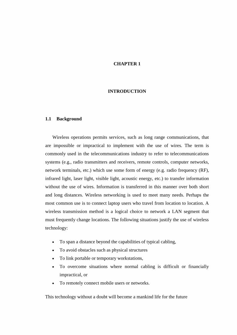
1.1 Background
Wireless operations permits services, such as long range communications, that
are impossible or impractical to implement with the use of wires. The term is
commonly used in the telecommunications industry to refer to telecommunications
systems (e.g., radio transmitters and receivers, remote controls, computer networks,
network terminals, etc.) which use some form of energy (e.g. radio frequency (RF),
infrared light, laser light, visible light, acoustic energy, etc.) to transfer information
without the use of wires. Information is transferred in this manner over both short
and long distances. Wireless networking is used to meet many needs. Perhaps the
most common use is to connect laptop users who travel from location to location. A
wireless transmission method is a logical choice to network a LAN segment that
must frequently change locations. The following situations justify the use of wireless
technology:
To span a distance beyond the capabilities of typical cabling,
To avoid obstacles such as physical structures
To link portable or temporary workstations,
To overcome situations where normal cabling is difficult or financially
impractical, or
To remotely connect mobile users or networks.
This technology without a doubt will become a mankind life for the future
2
1.2 Objective of Project
The main objective of this project is to be able to transfer data from hardware
using wireless system and create a data logger to display the current speed and
direction of the wind on computer.
1.3 Scope of Project
In order to achieve the objective of the project, several scopes have been
outlined. The scope of this project are; understanding microcontroller PIC16F877
feature and working flow, using wireless technology as a transceiver medium
between hardware and software, create a data logger to display a measurement on
computer.
.
3
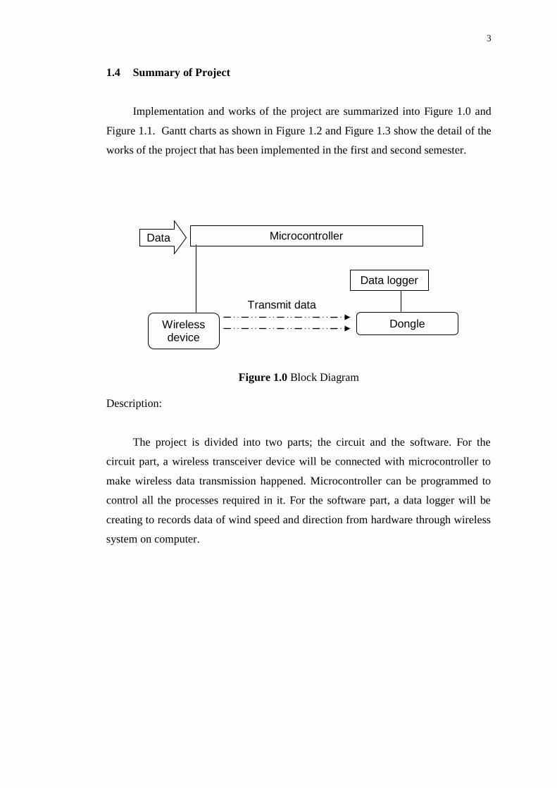
1.4 Summary of Project
Implementation and works of the project are summarized into Figure 1.0 and
Figure 1.1. Gantt charts as shown in Figure 1.2 and Figure 1.3 show the detail of the
works of the project that has been implemented in the first and second semester.
Figure 1.0 Block Diagram
Description:
The project is divided into two parts; the circuit and the software. For the
circuit part, a wireless transceiver device will be connected with microcontroller to
make wireless data transmission happened. Microcontroller can be programmed to
control all the processes required in it. For the software part, a data logger will be
creating to records data of wind speed and direction from hardware through wireless
system on computer.
Data Microcontroller
Wireless device
Dongle
Data logger
Transmit data

4
Figure 1.1 Flow Developments
Description:
Literature review and research on theories related to the project begins after
the title of the project was decided. These involve theories such as type wireless
technology, microcontroller and a few others. By obtaining most of the information
from the internet and a few reference book, the Zigbee wireless device was chosen to
be developed in this project because of it suitable function and features for this
project.
Project survey & literature
review
Determination type of wireless communication and software application
Create a data logger ( software)
Design and manufacturing circuit
Data analysis of wind speed and direction
Integration of hardware and software
End
5
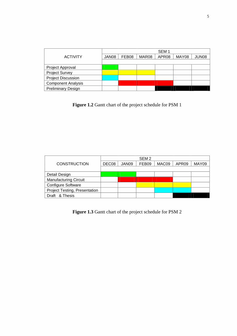
Figure 1.2 Gantt chart of the project schedule for PSM 1
Figure 1.3 Gantt chart of the project schedule for PSM 2
SEM 1
ACTIVITY JAN08 FEB08 MAR08 APR08 MAY08 JUN08
Project Approval
Project Survey
Project Discussion
Component Analysis
Preliminary Design
SEM 2
CONSTRUCTION DEC08 JAN09 FEB09 MAC09 APR09 MAY09
Detail Design
Manufacturing Circuit
Configure Software
Project Testing, Presentation
Draft & Thesis

6
CHAPTER 2
THEORY AND LITERATURE REVIEW
2.1 Introduction
This chapter includes the study of wireless technology, Bluetooth and
microcontroller. It‟s about the feature, application and adaptation. It also touches
slightly on other relevant hardware used in this project.
2.2 Wireless Communications
Wireless communications refers to technologies where information signals
are transferred is the transfer of information over a distance without the use of
electrical conductors or "wires". The distances involved may be short (a few meters
as in television remote control) or very long (thousands or even millions of
kilometers for radio communications). When the context is clear the term is often
simply shortened to "wireless". Wireless communications is generally considered to
be a branch of telecommunications. There are numerous applications for all the
different wireless technologies. General applications of wireless technologies are
divided into the voice and messaging, hand-held and other Internet-enabled devices,
and data networking. Although a traditional classification, this way of categorizing
wireless technologies also includes their differences in cost models, bandwidth,
coverage areas, etc.
7
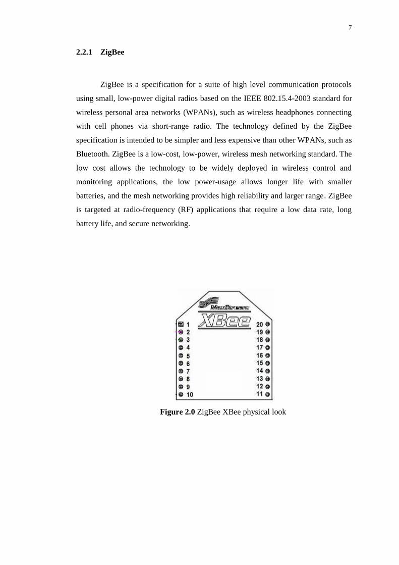
2.2.1 ZigBee
ZigBee is a specification for a suite of high level communication protocols
using small, low-power digital radios based on the IEEE 802.15.4-2003 standard for
wireless personal area networks (WPANs), such as wireless headphones connecting
with cell phones via short-range radio. The technology defined by the ZigBee
specification is intended to be simpler and less expensive than other WPANs, such as
Bluetooth. ZigBee is a low-cost, low-power, wireless mesh networking standard. The
low cost allows the technology to be widely deployed in wireless control and
monitoring applications, the low power-usage allows longer life with smaller
batteries, and the mesh networking provides high reliability and larger range. ZigBee
is targeted at radio-frequency (RF) applications that require a low data rate, long
battery life, and secure networking.
Figure 2.0 ZigBee XBee physical look
8
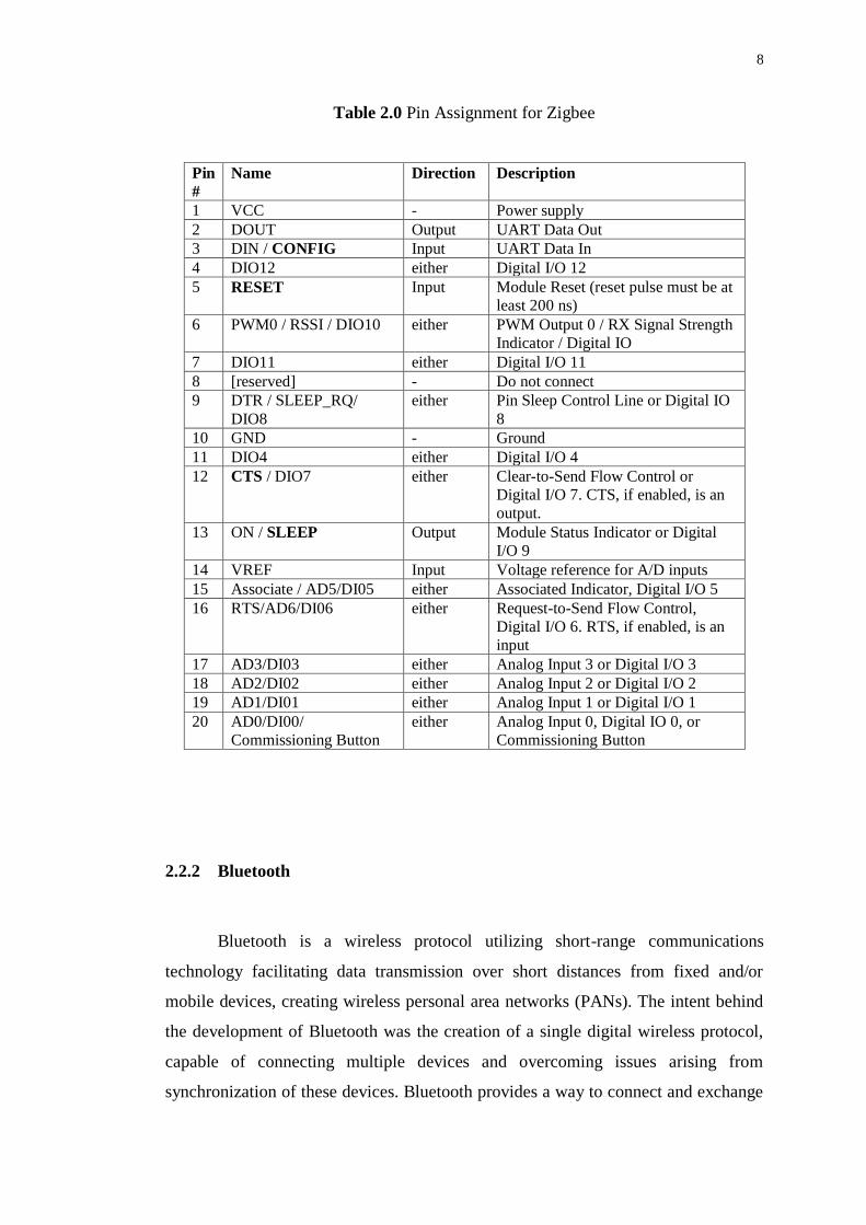
Table 2.0 Pin Assignment for Zigbee
Pin
#
Name Direction Description
1 VCC - Power supply
2 DOUT Output UART Data Out
3 DIN / CONFIG Input UART Data In
4 DIO12 either Digital I/O 12
5 RESET Input Module Reset (reset pulse must be at
least 200 ns)
6 PWM0 / RSSI / DIO10 either PWM Output 0 / RX Signal Strength
Indicator / Digital IO
7 DIO11 either Digital I/O 11
8 [reserved] - Do not connect
9 DTR / SLEEP_RQ/
DIO8
either Pin Sleep Control Line or Digital IO
8
10 GND - Ground
11 DIO4 either Digital I/O 4
12 CTS / DIO7 either Clear-to-Send Flow Control or
Digital I/O 7. CTS, if enabled, is an
output.
13 ON / SLEEP Output Module Status Indicator or Digital
I/O 9
14 VREF Input Voltage reference for A/D inputs
15 Associate / AD5/DI05 either Associated Indicator, Digital I/O 5
16 RTS/AD6/DI06 either Request-to-Send Flow Control,
Digital I/O 6. RTS, if enabled, is an
input
17 AD3/DI03 either Analog Input 3 or Digital I/O 3
18 AD2/DI02 either Analog Input 2 or Digital I/O 2
19 AD1/DI01 either Analog Input 1 or Digital I/O 1
20 AD0/DI00/
Commissioning Button
either Analog Input 0, Digital IO 0, or
Commissioning Button
2.2.2 Bluetooth
Bluetooth is a wireless protocol utilizing short-range communications
technology facilitating data transmission over short distances from fixed and/or
mobile devices, creating wireless personal area networks (PANs). The intent behind
the development of Bluetooth was the creation of a single digital wireless protocol,
capable of connecting multiple devices and overcoming issues arising from
synchronization of these devices. Bluetooth provides a way to connect and exchange

9
information and its technology specification for small form factor, low-cost, short-
range wireless links between devices such as mobile phones, telephones, laptops,
personal computers, printers, GPS receivers, digital cameras, and video game
consoles over a secure, globally unlicensed industrial.
2.2.3 Comparing ZigBee, Bletooth, Wi –Fi
Table 2.1 Compared between Zigbee, Bluetooth and Wi - Fi
Standard ZigBee®
802.15.4
Wi-Fi™
802.11b
Bluetooth™
802.15.1
Transmission
Range (meters)
1 – 100*
1 - 100
1 – 10
Battery Life (days) 100 – 1,000
0.5 – 5.0
1 - 7
Network Size (# of
nodes)
> 64,000
32
7
Application Monitoring &
Control
Web, Email,
Video
Cable Replacement
Stack Size (KB) 4 – 32
1,000
250
Throughput kb/s) 20 – 250
11,000
720
*XBeePRO yields 2 – 3x the range of standard Zigbee Modules (up to 1200 meter)
10
2.3 Microcontroller
Microcontrollers must contain at least two primary components – random
access memory (RAM), and an instruction set. RAM is a type of internal logic unit
that stores information temporarily. RAM contents disappear when the power is
turned off. While RAM is used to hold any kind of data, some RAM is specialized,
referred to as registers. The instruction set is a list of all commands and their
corresponding functions. During operation, the microcontroller will step through a
program (the firmware). Each valid instruction set and the matching internal
hardware are the features that differentiate one microcontroller from another [5].
Most microcontrollers also contain read-only memory (ROM), programmable
read-only memory (PROM), or erasable programmable read-only memory
(EPROM). Al1 of these memories are permanent: they retain what is programmed
into them even during loss of power. They are used to store the firmware that tells
the microcontroller how to operate. Often these memories do not reside in the
microcontroller; instead, they are contained in external ICs, and the instructions are
fetched as the microcontroller runs. This enables quick and low-cost updates to the
firmware by replacing the ROM.
The number of I/O pins per controllers varies greatly, plus each I/O pin can
be programmed as an input or output (or even switch during the running of a
program). The load (current draw) that each pin can drive is usually low. If the
output is expected to be a heavy load, then it is essential to use a driver chip or
transistor buffer.
Most microcontrollers contain circuitry to generate the system clock. This
square wave is the heartbeat of the microcontroller and all operations are
synchronized to it. Obviously, it controls the speed at which the microcontroller
functions. All that is needed to complete the clock circuit would be the crystal or RC
components. We can, therefore precisely select the operating speed critical to many
applications.
11
To summarize, a microcontroller contains (in one chip) two or more of the
following elements in order of importance:
i. Instruction set
ii. RAM
iii. ROM, PROM or EPROM
iv. I/O ports
v. Clock generator
vi. Reset function
vii. Watchdog timer
viii. Serial port
ix. Interrupts
x. Timers
xi. Analog-to-digital converters
xii. Digital-to-analog converters
2.3.1 PIC16F877A
PIC 16F877A is a microcontroller developed by Microchip Technology. It is
developed using RISC technology and only consists of 35 instructions set. It can run
on variable speed up to 20MHz. Beside that, the PIC draws low poser consumption
and provides a high speed Flash/EEPROM technology. The operating voltage range
is wide, as low as 2.0V up to 5.5V.

12
Figure 2.1 Physical look and diagram for PIC 16F877A
Features in PIC 16F877A;
1) Timer0: 8-bit timer/counter with 8-bit prescaler.
2) Timer1: 16-bit timer/counter with prescaler can be incremented during Sleep
via external crystal/clock.
3) Timer2: 8-bit timer/counter with 8-bit period register, prescaler and postscaler.
4) Two Capture, Compare, PWM modules;
- Capture is 16-bit, maximum resolution is 12.5 ns.
- Compare is 16-bit, maximum resolution is 200 ns.
- PWM maximum resolution is 10-bit.
5) Synchronous Serial Port (SSP) with SPI™ (Master mode) and I2C™
(Master/Slave).
6) Universal Synchronous Asynchronous Receiver.
7) Transmitter (USART/SCI) with 9-bit address detection.
8) Parallel Slave Port (PSP) – 8 bits wide with external RD, WR and CS controls
(40/44-pin only).
9) Brown-out detection circuitry for Brown-out Reset (BOR).

13
For analog features, the PIC 16F877A have 10 bits, 8 channels analog-to-
digital converter. With total of 5 I/O ports, the PIC16F877A is the most suitable
device for controlling a lot of controlling circuits.
The summary of PIC 16F877A features and specification is shown in table
below;
Table 2.2 PIC 16F877A features
Key Features PIC 16F877A
Operating Frequency DC – 20MHz
Reset (and delays) POR, BOR (PWRT, OST)
Flash Program Memory(14-bit words) 8K
Data Memory (bytes) 368
EEPROM Data Memory (bytes) 256
Interrupts 15
I/O Ports Ports A, B, C, D, E
Timers 3
Capture/Compare/PWM modules 2
Serial Communications MSSP, USART
Parallel Communications PSP
10-bit Analog-to-Digital Module 8 input Channels
Analog Comparators 2
Instruction Set 35 instructions
Packages 40-pin PDIP
44-pin PLCC
44-pin TQFP
44-pin QFN
14
2.3.1.1 Universal Synchronous Asynchronous Receiver (USART)
UART provides the ability to transmit data for one device to the other without
a complex set of wiring. Once the connections are made data can be sent and
received with the use of transmitting packets of data. Information such as start-stop
bits, data bits, and timing information can be conveyed from one end device to the
other. The Universal Asynchronous Receiver/Transmitter (UART) controller is the
key component of the serial communications subsystem of a computer. The UART
takes bytes of data and transmits the individual bits in a sequential fashion. At the
destination, a second UART re-assembles the bits into complete bytes. Serial
transmission of digital information (bits) through a single wire or other medium is
much more cost effective than parallel transmission through multiple wires.
A UART is used to convert the transmitted information between its sequential
and parallel form at each end of the link. Each UART contains a shift register which
is the fundamental method of conversion between serial and parallel forms. The
UART usually does not directly generate or receive the external signals used
between different items of equipment. Typically, separate interface devices are used
to convert the logic level signals of the UART to and from the external signaling
levels. External signals may be of many different forms. Examples of standards for
voltage signaling are RS-232, RS-422 and RS-485 from the EIA. Historically, the
presence or absence of current (in current loops) was used in telegraph circuits. Some
signaling schemes do not use electrical wires. Examples of such are optical fiber,
IrDA (infrared), and (wireless) Bluetooth in its Serial Port Profile (SPP).
Some signaling schemes use modulation of a carrier signal (with or without
wires). Communication may be "full duplex" (both send and receive at the same
time) or "half duplex" (devices take turns transmitting and receiving).As of 2008,
UARTs is commonly used with RS-232 for embedded systems communications. It is
useful to communicate between microcontrollers and also with PCs.
15
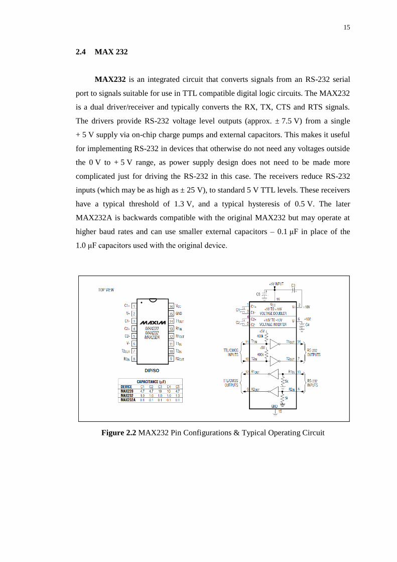
2.4 MAX 232
MAX232 is an integrated circuit that converts signals from an RS-232 serial
port to signals suitable for use in TTL compatible digital logic circuits. The MAX232
is a dual driver/receiver and typically converts the RX, TX, CTS and RTS signals.
The drivers provide RS-232 voltage level outputs (approx. ± 7.5 V) from a single
+ 5 V supply via on-chip charge pumps and external capacitors. This makes it useful
for implementing RS-232 in devices that otherwise do not need any voltages outside
the 0 V to + 5 V range, as power supply design does not need to be made more
complicated just for driving the RS-232 in this case. The receivers reduce RS-232
inputs (which may be as high as ± 25 V), to standard 5 V TTL levels. These receivers
have a typical threshold of 1.3 V, and a typical hysteresis of 0.5 V. The later
MAX232A is backwards compatible with the original MAX232 but may operate at
higher baud rates and can use smaller external capacitors – 0.1 μF in place of the
1.0 μF capacitors used with the original device.
Figure 2.2 MAX232 Pin Configurations & Typical Operating Circuit