development of a system architecture for unmanned systems
TRANSCRIPT
Dissertations and Theses
12-2014
Development of a System Architecture for Unmanned Systems Development of a System Architecture for Unmanned Systems
Across Multiple Domains Across Multiple Domains
Charles Randall Breingan Jr.
Follow this and additional works at: https://commons.erau.edu/edt
Part of the Automotive Engineering Commons, and the Mechanical Engineering Commons
Scholarly Commons Citation Scholarly Commons Citation Breingan, Charles Randall Jr., "Development of a System Architecture for Unmanned Systems Across Multiple Domains" (2014). Dissertations and Theses. 264. https://commons.erau.edu/edt/264
This Thesis - Open Access is brought to you for free and open access by Scholarly Commons. It has been accepted for inclusion in Dissertations and Theses by an authorized administrator of Scholarly Commons. For more information, please contact [email protected].
Development of a System Architecture for Unmanned Systems across Multiple
Domains
by
Charles Randall Breingan, Jr.
A Thesis Submitted to the College of Engineering Department of Mechanical Engineering
in Partial Fulfil lment of the Requirements fo r the Degree of Master of Science in
Mechanical Engineering
Embry-Riddle Aeronautical University
Daytona Beach, Florida
December 2014
iii
Acknowledgements
I would like to express my appreciation and thanks to my advisor Professor Dr. Patrick Currier,
you have been a tremendous mentor for me. I would like to thank you for encouraging my research and
for allowing me to grow as a research scientist. Your advice on both research as well as on my career
have been priceless. I would also like to thank my committee members, Dr. Reinholtz and Dr. Butka for
serving on my thesis committee.
I need to express my deepest appreciation to my advisers and friends Dr. Charles Reinholtz and
Dr. Brian Butka. Thank you Dr. Reinholtz for your continuing support and advice throughout my
education. Your confidence in me has meant a lot to me and has encouraged me to strive to be a better
student and a better engineer. Thank you to Dr. Butka for providing opportunities for me to participate
in fascinating research projects that I wouldn’t otherwise have had a chance to work on. The projects
that we have done together through our research have provided invaluable experiences and fantastic
education and insight. Thank you for pushing me to try hard and perform better, even when I was
perfectly content with taking the easy road to the end of a project.
I also have to thank my friends and colleagues in the Robotics Association. Specifically,
Christopher Hockley, Christopher Sammet, and Gene Gamble, who I worked with for many years, have
always helped me through the challenges that I have faced, both technical and personal. Even when we
disagreed, we could always discuss the differences of opinion and come to a reasonable compromise. I
have never worked with more talented or dedicated individuals, and I doubt I ever will.
Lastly, I need to convey my thanks to my family. Without their support, I never would have
made it to where I am today. Their love and support has been an integral part of my success throughout
my college career and I know that I can count on them as I move into my professional career.
iv
Abstract
Researcher: Charles Randall Breingan, Jr.
Title: Development of a System Architecture for Unmanned Systems across Multiple Domains
Institution: Embry-Riddle Aeronautical University
Degree: Master of Science in Mechanical Engineering
Year: 2014
In the unmanned systems industry, there is no common standard for system components,
connections, and relations. Such a standard is never likely to exist. Needless to say, a system needs to
have the components that are required for the application, however, it is possible to abstract the
common functionality out of an individual implementation. This thesis presents a universal unmanned
systems architecture that collects all of the common features of an unmanned system and presents
them as a set of packages and libraries that can be used in any domain of unmanned system operation.
The research and design of the universal architecture results in a well-defined architecture that can be
used and implemented on any unmanned system. The AUVSI student competitions are specifically
analyzed and it is shown how this universal architecture can be applied to the challenges posed by the
competitions in different domains.
v
Table of Contents Chapter 1 Introduction................................................................................................................................. 1
1.1 Background ......................................................................................................................................... 1
1.2 Literature Review ................................................................................................................................ 3
Chapter 2 System Requirements ............................................................................................................... 10
2.1 User Stories ....................................................................................................................................... 10
2.2 Domain Specific Requirements ......................................................................................................... 11
2.2.1 Unmanned Aerial Vehicles ......................................................................................................... 12
2.2.2 Unmanned Ground Vehicles ...................................................................................................... 13
2.2.3 Unmanned Surface Vehicles ...................................................................................................... 14
2.2.4 Unmanned Underwater Vehicles ............................................................................................... 15
2.3 Classification of Autonomy ............................................................................................................... 16
2.3.1 Perception .................................................................................................................................. 16
2.3.2 Intelligence ................................................................................................................................. 18
2.3.3 Independence ........................................................................................................................... 20
Chapter 3 U2SA Architecture Specification ............................................................................................... 22
3.1 Architectural Design Pattern ............................................................................................................. 22
3.2 Logical Architecture .......................................................................................................................... 24
3.2.1 Service Interfaces ....................................................................................................................... 29
3.2.2 Abstract Services ........................................................................................................................ 34
3.2.3 Core Services .............................................................................................................................. 40
3.2.3 Messaging Data Models ............................................................................................................. 45
3.3 Implementation Architecture ........................................................................................................... 59
3.3.1 Interface Layer ........................................................................................................................... 61
3.3.2 Abstract Layer ............................................................................................................................ 62
3.3.3 Core Layer .................................................................................................................................. 62
3.3.4 Interaction Layer ........................................................................................................................ 62
3.4 Process Architecture ......................................................................................................................... 63
3.5 Deployment Architecture ................................................................................................................. 64
3.5.1 Packaging ................................................................................................................................... 65
3.5.2 Processing Distribution .............................................................................................................. 68
3.5.3 Process Availability..................................................................................................................... 68
Chapter 4 Scenarios and Implementations ................................................................................................ 70
4.1 Intelligent Ground Vehicle Competition ........................................................................................... 70
4.1.1 U2SA Implementation ................................................................................................................ 72
vi
4.1.2 U2SA Advantages ....................................................................................................................... 76
4.2 RoboBoat Competition ..................................................................................................................... 78
4.2.1 Sensing ....................................................................................................................................... 80
4.2.2 Perception .................................................................................................................................. 81
4.2.3 Intelligence ................................................................................................................................. 82
4.2.4 Control ....................................................................................................................................... 85
4.2.5 Actuation .................................................................................................................................... 86
4.3 RoboSub Competition ....................................................................................................................... 86
4.3.1 Sensing ....................................................................................................................................... 88
4.3.2 Perception .................................................................................................................................. 88
4.3.3 Intelligence ................................................................................................................................. 89
4.3.4 Control ....................................................................................................................................... 91
4.3.5 Actuation .................................................................................................................................... 91
4.4 Student Unmanned Aerial Systems Competition ............................................................................. 92
4.4.1 Sensing ....................................................................................................................................... 94
4.4.2 Perception .................................................................................................................................. 95
4.4.3 Intelligence ................................................................................................................................. 95
4.4.4 Control ....................................................................................................................................... 96
4.4.5 Actuation .................................................................................................................................... 97
4.5 U2SA FlightGear Implementation ..................................................................................................... 98
4.5.1 Interfaces ................................................................................................................................... 99
4.5.2 Services .................................................................................................................................... 100
4.5.3 Lessons Learned ....................................................................................................................... 104
4.6 U2SA Ground Vehicle Implementation ........................................................................................... 104
4.6.1 Interfaces ................................................................................................................................. 105
4.6.2 Services .................................................................................................................................... 106
4.6.3 Hardware ................................................................................................................................. 109
Chapter 5 U2SA Analysis .......................................................................................................................... 111
5.1 Requirements Traceability .............................................................................................................. 111
5.2 Principles of a SOA .......................................................................................................................... 116
5.2.1 Standardized Service Contracts ............................................................................................... 116
5.2.2 Service Loose Coupling ............................................................................................................ 117
5.2.3 Service Abstraction .................................................................................................................. 117
5.2.4 Service Reusability ................................................................................................................... 118
5.2.5 Service Autonomy .................................................................................................................... 118
vii
5.2.6 Service Statelessness ............................................................................................................... 119
5.2.7 Service Discoverability ............................................................................................................. 119
5.2.8 Service Composability .............................................................................................................. 119
5.3 Limitations................................................................................................................................. 120
Chapter 6 Conclusions.............................................................................................................................. 122
Chapter 7 References ............................................................................................................................... 124
Chapter 8 Appendices .............................................................................................................................. 126
8.1 List of Acronyms ........................................................................................................................ 126
viii
Table of Figures Figure 1: 4+1 View Model ............................................................................................................................. 9 Figure 2: Component Breakdown ............................................................................................................... 26 Figure 3: Inheritance Diagram .................................................................................................................... 28 Figure 4: Service/Message Dependency Diagram ...................................................................................... 47 Figure 5: U2SA Data Model ......................................................................................................................... 48 Figure 6: State Information Data Model ..................................................................................................... 50 Figure 7: Goal Information Data Model ...................................................................................................... 52 Figure 8: Waypoint Data Model .................................................................................................................. 53 Figure 9: Object Description Data Model ................................................................................................... 54 Figure 10: Point Cloud Data Model ............................................................................................................. 56 Figure 11: Shape Description Data Model with Example Shapes ............................................................... 57 Figure 12: Navigation Point Data Model ..................................................................................................... 58 Figure 13: Actuator Command Data Model ................................................................................................ 59 Figure 14: U2SA Package Diagram .............................................................................................................. 60 Figure 15: Implementation Layer Diagram ................................................................................................. 61 Figure 16: Data Flow Diagram ..................................................................................................................... 64 Figure 17: IGVC Data Flow Diagram ............................................................................................................ 71 Figure 18: RoboBoat Data Flow Diagram .................................................................................................... 80 Figure 19: RoboBoat State Diagram ............................................................................................................ 85 Figure 20: RoboSub Data Flow Diagram ..................................................................................................... 87 Figure 21: RoboSub State Diagram ............................................................................................................. 90 Figure 22: SUAS Data Flow Diagram ........................................................................................................... 94 Figure 23: FlightGear Implementation Data Flow Diagram ...................................................................... 101 Figure 24: UGV Implementation Data Flow Diagram ............................................................................... 105 Figure 25: UGV Implementation Hardware .............................................................................................. 109
List of Tables Table 1: Architecture Comparison ................................................................................................................ 8 Table 2: Potential UAV Inputs ..................................................................................................................... 12 Table 3: Potential UAV Outputs .................................................................................................................. 13 Table 4: Potential UGV Inputs ..................................................................................................................... 13 Table 5: Potential UGV Outputs .................................................................................................................. 14 Table 6: Potential USV Inputs ..................................................................................................................... 14 Table 7: Potential USV Outputs .................................................................................................................. 15 Table 8: Potential UUV Inputs ..................................................................................................................... 15 Table 9: Potential UUV Outputs .................................................................................................................. 16
1
Chapter 1 Introduction
1.1 Background
In the engineering domain, there are an infinite number of solutions to any given problem.
However, from time to time, a solution is accepted as being standard practice and most solutions going
forward tend to align with the accepted standard. Every time that such a standard has been adopted, it
has bounded the technology forward by allowing new development to build upon the existing
technology. When original processor architectures were standardized by Intel, all of the machines using
those processors were interoperable. It was much easier to write a program on one processor and
distribute that program to other users with the same processor. When USB became a standard it
allowed manufacturers to create many different peripherals to attach to any machine that implements
the USB standard. The input and output capabilities of computers have expanded dramatically since the
USB standard was adopted.
This type of accepted solution has not yet come about in the field of unmanned systems. There
are many different types of architectures that are designed to do a specific task. Examples of such
architectures are systems that have been custom designed to fly an airplane, or to drive a car, or to pilot
a boat. However, each time one of these systems is designed, it is done from the ground up. While there
are many similarities between these systems and how they make decisions, not much software is reused
from applications. A significant amount of engineering overhead is added to every design project by not
adopting an architectural standard for unmanned systems.
2
The purpose of this study is to propose a standard architecture, the Universal Unmanned
Systems Architecture (U2SA), for unmanned systems that can apply to all of the different domains in
which unmanned systems operate. The architecture is capable of supporting the simplest one
dimensional unmanned systems, like elevators and conveyors belts, as well as the most complicated
unmanned systems, like artificial intelligence.
Each domain of unmanned systems is vastly different in terms of sensors, actuators, and
missions. However, there are also many similarities between the domains. A universal architecture that
extracts all of the common functions of an unmanned system is necessary for the progress of the
unmanned systems industry. If this architecture can encapsulate the common functionality while still
allowing for domain specific and implementation specific interfaces, then the unmanned systems
developed from this architecture will be able to build off of the previous work and simply add new
features rather than reinventing the wheel. The U2SA will provide the common baseline architecture
that could be utilized by any unmanned systems project that is looking to expand on functionality that
already exists.
This thesis will propose a universal architecture that can be applied to each of the 4 primary
unmanned systems domains. The architecture may also be able to support domains outside of the
primary four, such as space vehicles or underground robots, however these domains are not analyzed.
The architecture will extract the software and system components that are necessary to develop an
unmanned system from any domain. It will also specify the connections between components and the
configuration properties of the components and the connections. In chapter 2, the requirements that
are used to design the architecture are described. Chapter 3 will present the 4 architectural views that
are necessary to describe a system architecture. In chapter 4, applications in the different domains of
unmanned systems will be analyzed and a solution that is built from the U2SA will be proposed for each
3
problem area. Chapter 5 will describe how the U2SA has met the requirements and is designed within
the principles of a typical system architecture. Chapter 6 will offer conclusions and identify areas of
future research for unmanned systems.
1.2 Literature Review
The Joint Architecture for Unmanned Systems (JAUS) was developed as part of a Department of
Defense (DoD) initiative in 1998 [1]. JAUS was meant to create the standard for unmanned system
architectures by which all current and future unmanned system developers would create their products.
The JAUS specification was created to allow developers the freedom to not only create new systems, but
also to incorporate legacy systems into the new JAUS architecture. For this reason, the JAUS standard
was defined as a system of nodes and components and JAUS specified only the data interaction between
systems, nodes, and components. Certain nodes and components are defined in the JAUS standard and
each node and component is responsible for a specific set of operations. However, not all applications
may require the types of operations that are required by JAUS components. Additionally, JAUS nodes
and components need to be aware of the other nodes and component IDs or the communication
between modules will fail. JAUS had a well-defined communication protocol that can be useful to any
number of application, but the process architecture may have been defined too rigidly for practical use
in a system design process [2]. The DoD abandoned JAUS in 2012 because it was not being utilized by
vendors. It is important to note that the concepts behind JAUS have contributed greatly to the U2SA.
Some systems, like the ArduPilot, utilize the MAVLink data protocol which is an extension of the
protocol contained within JAUS [3]. Extending the JAUS protocol gives MAVLink a good start at creating
a well-defined protocol. One of the biggest advantages of MAVLink over JAUS is that MAVLink support
blind publishing of messages where a software module does not need to know about other software
modules in the system. However, the ArduPilot software only has one monolithic piece of software and
4
the concept of inter-process communication is not possible in a single process. Thus, the MAVLink
protocol is only utilized for communicating with outside entities like a ground control station.
The National Institute for Standards and Technology has published the 4D/RCS Reference Model
Architecture for Intelligent Unmanned Ground Vehicles in 2002 [4]. The 4D/RCS presents a layered
approach to an unmanned ground vehicle implementation for the Army Research Laboratory Demo III
program. The layers of the 4D/RCS includes the Battalion Map, Platoon Map, Section Map, Vehicle Map,
Subsystem Map, Entity Images, and Signal States layers. Each layer plans vehicle operation for the next
time step that is defined for that layer. At the extremes of the layers, the Battalion Map plans for the
next 24 hours whereas the Signal States layer plans for the next 0.05 seconds. These layers are
specifically designed for multi-vehicle operation in an environment. The 4D/RCS then breaks down an
individual vehicle’s implementation of the architecture. For any given ground vehicle there are 4
processes that are continuously executing: behavior generation, world modeling, sensory processing,
and value judgment. Each process communicates with each of the other processes resulting in highly
coupled process modules. The 4D/RCS presents a highly coupled process architecture and leaves out the
logical architecture for software components and data models. The coupling, timing constraints, and
lack of architectural depth may be the reason that the 4D/RCS has received criticism over the years since
its inception. [5]
One of the most prevalent autopilot solutions in the hobby industry is often overlooked as a
valuable solution by academic research. The ArduPilot system is an open source hardware and software
application that was originally designed to control fixed wing hobby aircraft. Since its initial
development, the ArduPilot has expanded to include rotorcraft, multi-rotors, and ground vehicles [5].
Each of the different applications are compiled onto the ArduPilot hardware which is an ATmega 2560
microprocessor. Since the ArduPilot is built onto the ATmega, these projects are limited to a single
5
thread of execution. ArduPilot projects are also limited to 8 PWM inputs, 8 PWM outputs, and 14 digital
General Purpose I/O (GPIO). The software of the ArduPilot is purely sequential and utilizes a series of
highly coupled functions that share the same memory space and access variables globally.
In 2013, Breingan and Currier presented a paper on creating an Autopilot Architecture for
Advanced Autonomy [6] at the AUVSI Unmanned Systems, North America conference. This paper
proposed the Embry-Riddle Autopilot Solution for Multiple Unmanned Systems (ERASMUS) Architecture,
an autopilot architecture for aircraft to allow for future integration into the national airspace. ERASMUS
was designed for implementation on an Android smartphone or other Java processor. The U2SA
proposed in this thesis is a direct descendent of ERASMUS. After the publication of this paper, ERASMUS
was implemented for research of this thesis and the U2SA is the refinement of the ERASMUS
architecture.
Throughout the years of unmanned systems development, many government and private
agencies have tried to define levels of autonomous behavior. These agencies include the DoD Joint
Program Office, the Army Maneuver Support Center, National Institute of Standards and Technology,
Army Future Combat Systems, and the Air Force Research Laboratory [7] [8] [9] [11]. In 2005 the DoD
assembled a group of researchers to create the Autonomy Levels For Unmanned Systems (ALFUS) [8].
This group developed metrics for determining levels of autonomy. The 3 degrees of measuring
autonomy are mission complexity, environmental difficulty, and human independence. These
dimensions are a good start to the problem of classifying autonomy, however they have one flaw that
makes them inadequate for this study. The flaw with these dimensions is that they are not in reference
to the system, but the environment outside of the system. A system can be programmed to do one
specific complex mission very well and would therefore have a high score for mission complexity.
Likewise, a system can be designed for a complex environment, but not really be able to handle
6
different, or even more simple terrains and environments. Lastly, a system could score very highly in the
human independence for one task, but score very poorly on a different task than what it was designed
to do.
The Air Force Research Lab (AFRL) also developed metrics for measuring the autonomy of an
unmanned system. In 2002 AFRL published a paper titled “Metrics Schmetrics” [8] was presented as a
first step towards standardizing the classification of autonomy. This scheme of classification defined 11
levels of autonomy with level zero being remotely piloted vehicles and level ten being fully autonomous
[10]. Each level has a rigid definition of how the system perceives, analyzes, makes decisions, and acts.
The Autonomous Control Logic metrics were a good first step in defining autonomy, however the
metrics are specifically designed for military UAV applications. Using terms like “battlespace” and
“inferred threat tactics” to describe a level of autonomy somewhat limits the usefulness of these
metrics outside of military applications. Additionally, the rigidness of the levels limits the ability to
communicate the ability of a more advanced perception algorithm if the decision making is limited.
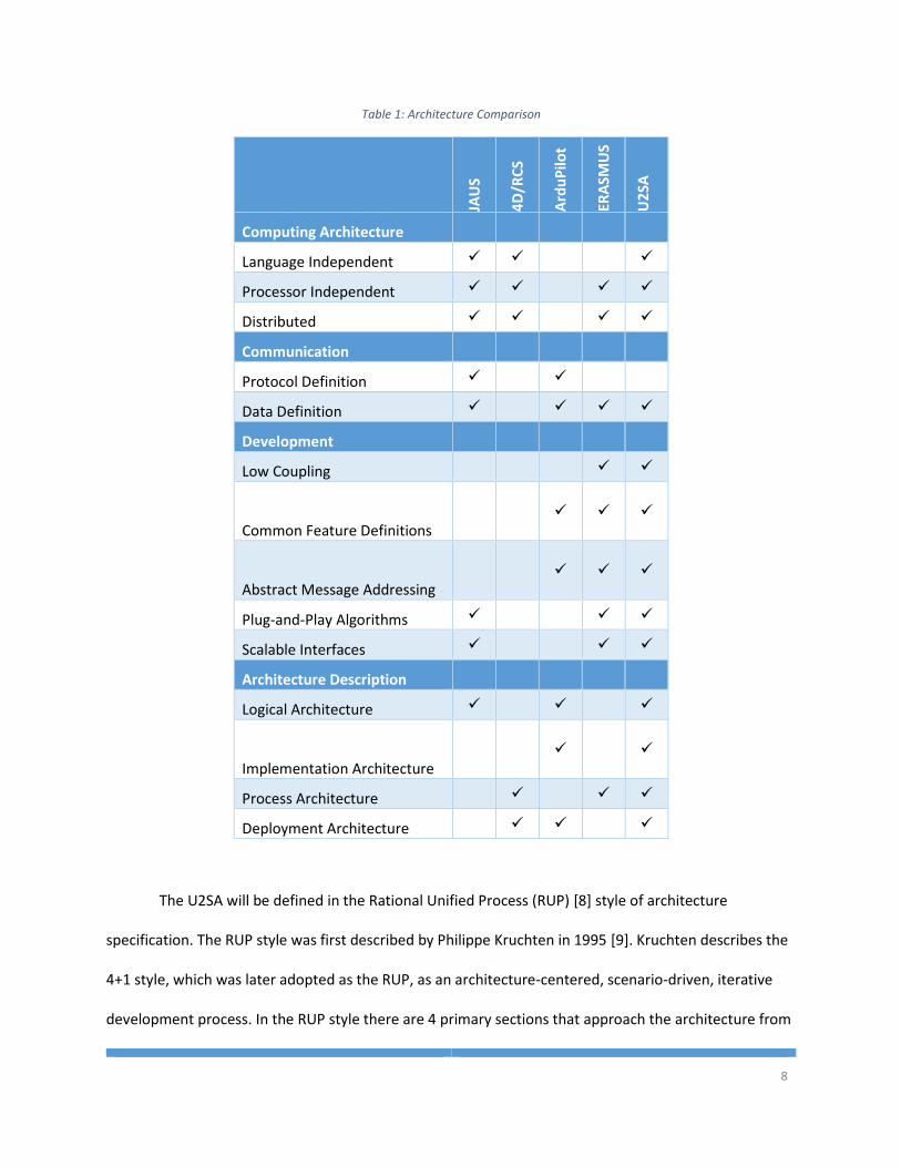
A summary of the different system architectures discussed here is shown below in

7
Table 1. The features outlined in the table below are discussed above as advantages and disadvantages
of each architecture definition and will be used late in this thesis to define what features the U2SA
should provide.
8
Table 1: Architecture Comparison
JAU
S
4D
/RC
S
Ard
uP
ilot
ERA
SMU
S
U2
SA
Computing Architecture
Language Independent
Processor Independent
Distributed
Communication
Protocol Definition
Data Definition
Development
Low Coupling
Common Feature Definitions
Abstract Message Addressing
Plug-and-Play Algorithms
Scalable Interfaces
Architecture Description
Logical Architecture
Implementation Architecture
Process Architecture
Deployment Architecture
The U2SA will be defined in the Rational Unified Process (RUP) [8] style of architecture
specification. The RUP style was first described by Philippe Kruchten in 1995 [9]. Kruchten describes the
4+1 style, which was later adopted as the RUP, as an architecture-centered, scenario-driven, iterative
development process. In the RUP style there are 4 primary sections that approach the architecture from
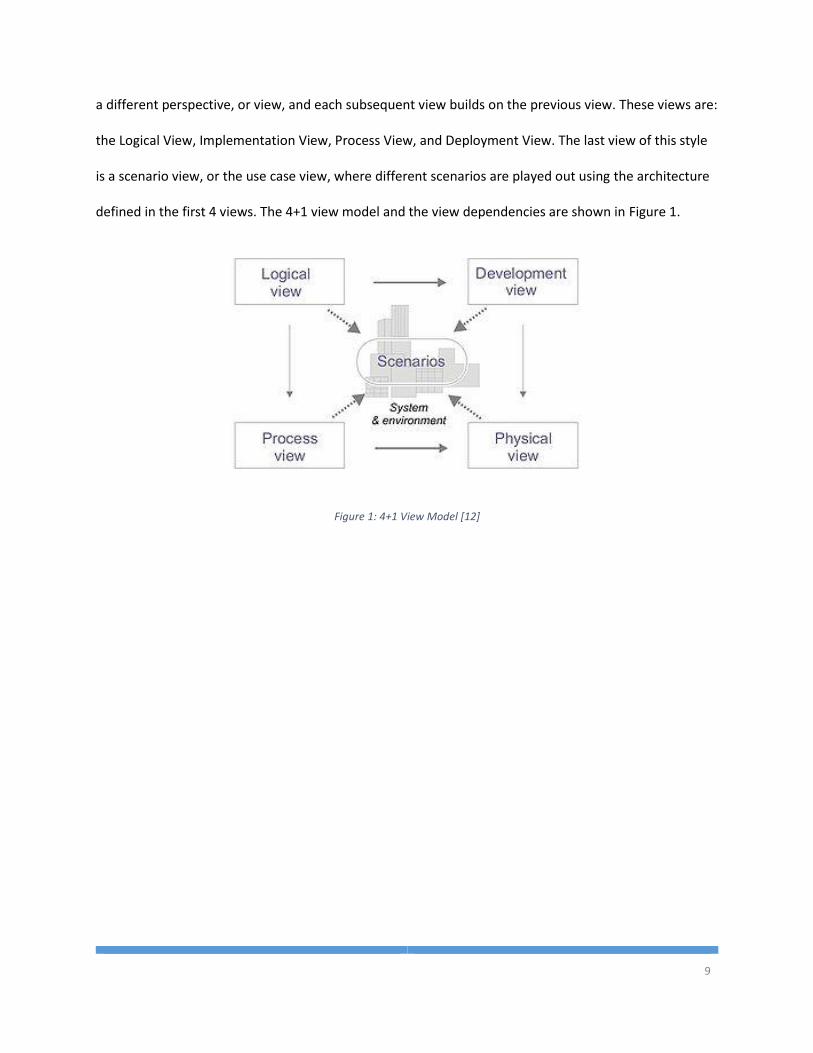
9
a different perspective, or view, and each subsequent view builds on the previous view. These views are:
the Logical View, Implementation View, Process View, and Deployment View. The last view of this style
is a scenario view, or the use case view, where different scenarios are played out using the architecture
defined in the first 4 views. The 4+1 view model and the view dependencies are shown in Figure 1.
Figure 1: 4+1 View Model [12]
10
Chapter 2 System Requirements
The U2SA will define an architecture that software and system developers can utilize to create
their unmanned systems. The primary stakeholders in the U2SA are the engineers and developers that
will implement the architecture in their application. Thus, a majority of the effort in designing the
architecture should be to meeting the developers’ needs for an unmanned system.
2.1 User Stories
A common way to capture system requirements is to collect user stories from the end users of
the system [10]. A user story is a natural language description of a piece of functionality that the end
user would like to have. User stories are usually in the format of “As a <role>, I want <desire> so that
<benefit>.” This type of requirement solicitation is very useful for collecting, not only the requirement,
but also the sentiment behind the end users story and the benefit that the requirement provides to the
project. The following user stories have been collected from student researchers at Embry-Riddle,
researchers in industry, and from personal experiences to help define exactly what this architecture
needs to specify.
1. As a leader of a development team, I would like the developers to be able to create independent
software modules in different programming languages so that development is faster and easier
for the developers.
2. As a developer, I would like a well-defined communication protocol for the data that needs to
be communicated between software modules so that modules can be developed independently.
11
3. As a system engineer, I would like the software to be processor and computer architecture
independent so that the system can be ported to a new computer without additional
development.
4. As a system engineer, I would like the software modules to maintain the lowest coupling
possible so that modules can be developed or modified independently.
5. As a system engineer, I would like the software modules to run seamlessly on a distributed
computing platform with minimal configuration so that the end user doesn’t have to spend time
configuring each module when process distribution changes.
6. As a leader of a development team, I would like the common features of a software module to
be defined and abstracted so that developers do not spend time re-implementing already
implemented functionality.
7. As a leader of a development team, I would like the communication between software modules
to be lowly coupled so that modules do not need to be aware of other modules within the
system.
8. As a system engineer, I would like to be able to seamlessly pick and replace navigation
algorithms like sensor filtering, path planning, and control systems so that different algorithms
can be tested quickly and efficiently.
9. As a system engineer, I would like to add a new sensor or actuator to the system without having
to change my state estimation, world modeling, or control algorithms and code base so that the
development time in adding a new device is reduced.
2.2 Domain Specific Requirements
The U2SA should support unmanned systems from all of the different domains of operation, and
it must be able to support the four primary domains. The primary domains are Unmanned Ground
12
Vehicles (UGV), Unmanned Aerial Vehicles (UAV), Unmanned Surface Vehicles (USV), Unmanned
Underwater Vehicles (UUV), and every amalgamation of the above. Therefore, before designing the
architecture, a list of domain specific requirements must be created in order for the architecture to
sufficiently support each domain without infringing on overall functionality.
2.2.1 Unmanned Aerial Vehicles
A UAV operates in 6 degrees of freedom and must be able to communicate movement
information for each of those dimensions. UAVs have a unique requirement of needing to distinguish
between a ground reference frame and an air reference frame. UAVs require location and attitude
sensing which they can get from Global Positioning Systems (GPS) and Inertial Measurement Units
(IMU). A UAV requires, not only ground speed, but also air speed, angle of attack, barometric pressure,
and, as airspace integration continues, it will need to sense or communicate location data with other
aircraft. A UAV could use Radio Detection and Ranging (RADAR) or Automatic Dependent Surveillance-
Broadcast (ADS-B) to detect other aircraft in the area for avoidance purposes. In addition to these
inputs, a UAV has numerous outputs. Depending on the widely varied types of aircraft, different control
surfaces need to be commanded and manipulated, as well as various types of propulsion. UAVs also
typically have other peripherals that are needed to complete whatever task or mission they are
currently attempting. Peripherals may include cameras, gimbals, and dropping/releasing items or
ordnances.
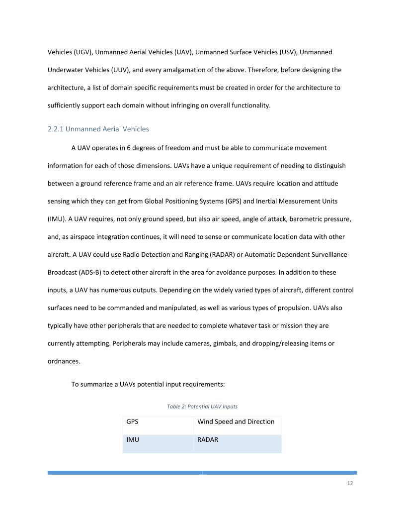
To summarize a UAVs potential input requirements:
Table 2: Potential UAV Inputs
GPS Wind Speed and Direction
IMU RADAR
13
Airspeed ADS-B
Barometric Pressure Camera
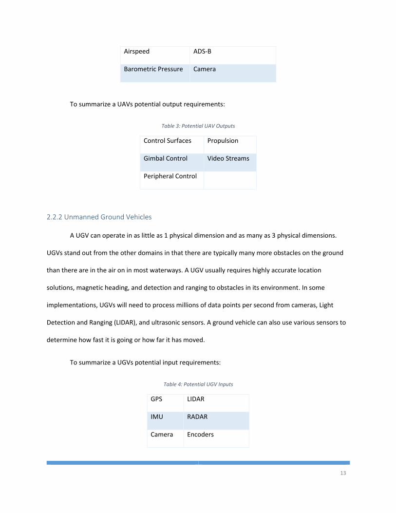
To summarize a UAVs potential output requirements:
Table 3: Potential UAV Outputs
Control Surfaces Propulsion
Gimbal Control Video Streams
Peripheral Control
2.2.2 Unmanned Ground Vehicles
A UGV can operate in as little as 1 physical dimension and as many as 3 physical dimensions.
UGVs stand out from the other domains in that there are typically many more obstacles on the ground
than there are in the air on in most waterways. A UGV usually requires highly accurate location
solutions, magnetic heading, and detection and ranging to obstacles in its environment. In some
implementations, UGVs will need to process millions of data points per second from cameras, Light
Detection and Ranging (LIDAR), and ultrasonic sensors. A ground vehicle can also use various sensors to
determine how fast it is going or how far it has moved.
To summarize a UGVs potential input requirements:
Table 4: Potential UGV Inputs
GPS LIDAR
IMU RADAR
Camera Encoders
14
Ultrasonic IR Range Detectors
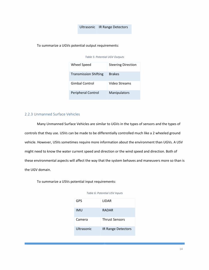
To summarize a UGVs potential output requirements:
Table 5: Potential UGV Outputs
Wheel Speed Steering Direction
Transmission Shifting Brakes
Gimbal Control Video Streams
Peripheral Control Manipulators
2.2.3 Unmanned Surface Vehicles
Many Unmanned Surface Vehicles are similar to UGVs in the types of sensors and the types of
controls that they use. USVs can be made to be differentially controlled much like a 2 wheeled ground
vehicle. However, USVs sometimes require more information about the environment than UGVs. A USV
might need to know the water current speed and direction or the wind speed and direction. Both of
these environmental aspects will affect the way that the system behaves and maneuvers more so than is
the UGV domain.
To summarize a USVs potential input requirements:
Table 6: Potential USV Inputs
GPS LIDAR
IMU RADAR
Camera Thrust Sensors
Ultrasonic IR Range Detectors
15
Wind Sensors Current Sensors
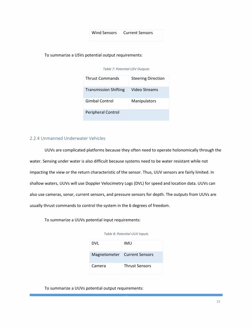
To summarize a USVs potential output requirements:
Table 7: Potential USV Outputs
Thrust Commands Steering Direction
Transmission Shifting Video Streams
Gimbal Control Manipulators
Peripheral Control
2.2.4 Unmanned Underwater Vehicles
UUVs are complicated platforms because they often need to operate holonomically through the
water. Sensing under water is also difficult because systems need to be water resistant while not
impacting the view or the return characteristic of the sensor. Thus, UUV sensors are fairly limited. In
shallow waters, UUVs will use Doppler Velocimetry Logs (DVL) for speed and location data. UUVs can
also use cameras, sonar, current sensors, and pressure sensors for depth. The outputs from UUVs are
usually thrust commands to control the system in the 6 degrees of freedom.
To summarize a UUVs potential input requirements:
Table 8: Potential UUV Inputs
DVL IMU
Magnetometer Current Sensors
Camera Thrust Sensors
To summarize a UUVs potential output requirements:
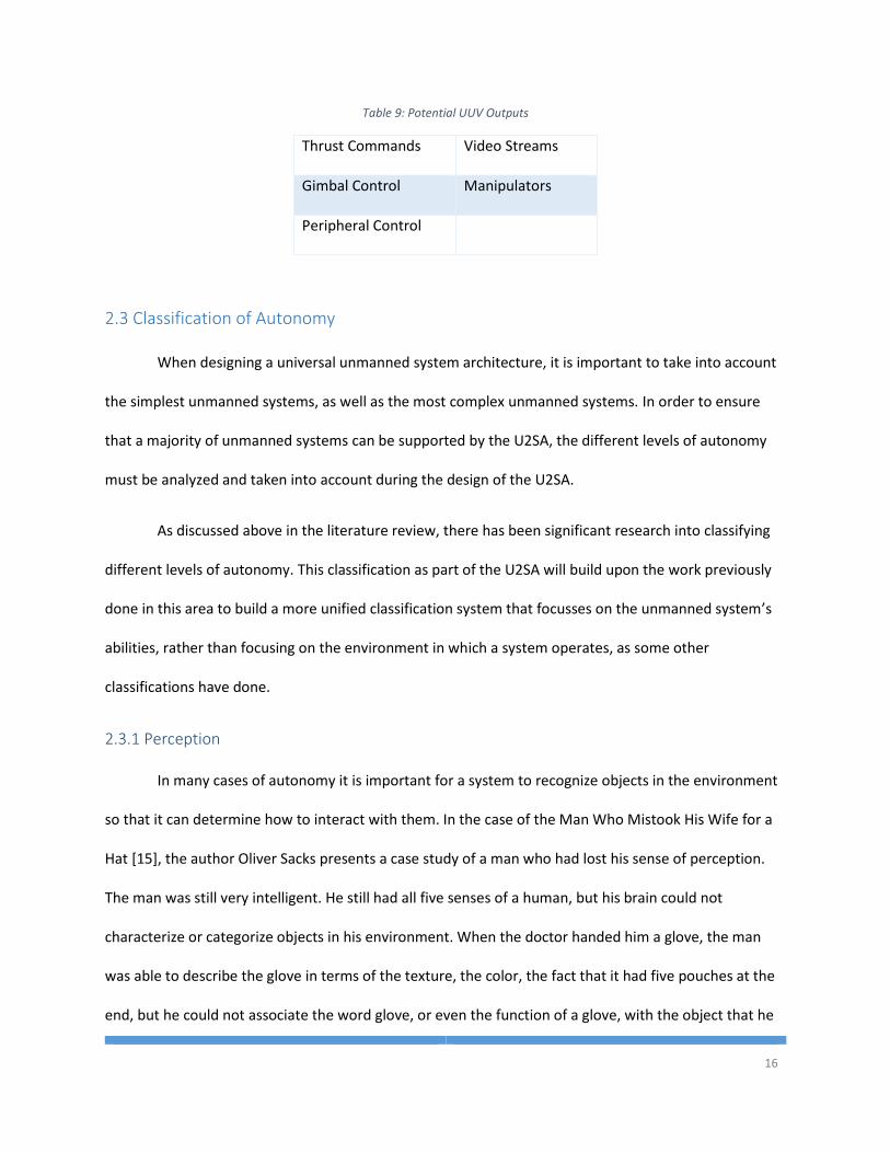
16
Table 9: Potential UUV Outputs
Thrust Commands Video Streams
Gimbal Control Manipulators
Peripheral Control
2.3 Classification of Autonomy
When designing a universal unmanned system architecture, it is important to take into account
the simplest unmanned systems, as well as the most complex unmanned systems. In order to ensure
that a majority of unmanned systems can be supported by the U2SA, the different levels of autonomy
must be analyzed and taken into account during the design of the U2SA.
As discussed above in the literature review, there has been significant research into classifying
different levels of autonomy. This classification as part of the U2SA will build upon the work previously
done in this area to build a more unified classification system that focusses on the unmanned system’s
abilities, rather than focusing on the environment in which a system operates, as some other
classifications have done.
2.3.1 Perception
In many cases of autonomy it is important for a system to recognize objects in the environment
so that it can determine how to interact with them. In the case of the Man Who Mistook His Wife for a
Hat [15], the author Oliver Sacks presents a case study of a man who had lost his sense of perception.
The man was still very intelligent. He still had all five senses of a human, but his brain could not
characterize or categorize objects in his environment. When the doctor handed him a glove, the man
was able to describe the glove in terms of the texture, the color, the fact that it had five pouches at the
end, but he could not associate the word glove, or even the function of a glove, with the object that he
17
was holding. The man frequently needed help with things, his wife was crucial in making sure he could
get dressed in the morning and eat his breakfast. In this case, the man who lost his perception was still
highly intelligent, but he had lost some part of his autonomy. He could no longer operate completely
independently. For these reasons, we find that perception of the environment is a primary metric for
autonomy, in humans and robotics.
1. No Sensing
In this level of sensing there are no sensors attached to the system and no continuous inputs
from the internal system or the external world. With no sensor data, there is nothing to process,
there is nothing to perceive except a priori knowledge of the environment.
2. Discrete
This level of sensing includes sensors that are relevant for the mission and the system collects
data describing the external world, but there is no grouping or classification. The system
operates solely on discrete data points returned from the sensor. It does not try to perceive the
whole picture, or the object as a whole.
3. Grouped
At this level, systems will be able to sense objects in the environment and group nearby data
points. Here, the system reads data from the sensors and can group similar data points that
seem to be part of the same object. The system could determine: ‘there is a blob over to my
right that is X size and Y distance away.’ But it does not determine what that blob is. The system
interacts with all blobs in the world model the same way (ex. always avoid or always seek).
4. Classification
This level of perception is not only grouping nearby sensor data points into clusters or blobs, but
also determining what that blob is. This level of perception would include a limited set of pre-
18
programmed object characteristics that would allow the system to determine if the cluster of
data points is one of the pre-programmed objects. (ex. Red buoy vs green buoy).
5. Static Learning
Learning new objects would allow the system to expand its’ object library from level 4
perception. This type of learning would require teaching with numerous data points and a
specific learning mode. The system would not be able to learn new objects for classification on
its own.
6. Dynamic Learning
The system would have the ability to learn to classify new objects in the environment through
normal operation. This level of learning would be equivalent to an adult human seeing an object
for the first time and then being able to recognize that object again in the future.
2.3.2 Intelligence
With perception a system can obtain information about the external world from internal a priori
knowledge or sensors that observe the environment. However, the next stage of autonomy is deciding
what to do with that information. Consider the way that humans take in information and then make
decisions based on that information. Humans make plans, draw conclusions, and act on the information
that is given to them. The ability to make decisions is an important part of an unmanned system’s
operation. The complexity of the decision making process makes up the intelligence aspect of
autonomy.
1. No Decisions
At this level of intelligence, the system is not capable of making decisions. The system operates
on pre-programmed maneuvers based on time. No sensor data is taken into account. This is
lowest level of intelligence.
19
2. Static Response
Systems at this level of intelligence operate in static environments with known objects and
obstacles. When it sees a certain type of object it performs a preprogrammed maneuver.
3. Memory
At this level of intelligence, the system can maintain memory of the environment. In a dynamic
environment being able to remember the area that is no longer within sensor range is integral
to intelligence. In this level of intelligence memory might be in static or dynamic environments.
4. Projection
This level of intelligence allows the system to operate in a dynamic environment where objects
are moving. This level of intelligence would allow the system to determine what an object is
doing and how fast it is doing it; thus being able to plan for where objects will be at time of
interception.
5. Static Task Learning
The fifth level of intelligence includes the ability to learn how to do new tasks. A system at this
level could watch a person perform a task and learn how to accomplish the task. The system will
have a learning mode during which it observes a task being done and an operation mode where
is duplicates the procedure that it observed during learning.
6. Dynamic Task Learning
At the highest level of intelligence, a system will be able to develop a new solution to a problem
without guidance from a higher intelligence. There is no “learning mode” at this level of
intelligence, the system is constantly observing and maintaining memory of the things that it
sees.
20
2.3.3 Independence
The third dimension of measuring autonomy, is the independence of the system. How well can a
system operate on its own without intervention? The ability to operate independently from human
intervention is crucial for autonomy. As with all of the dimensions of autonomy, the highest level
considered is that of a human. Thus, consider a human that lives on their own who must collect food,
build shelter, and maintain their health. Likewise, an autonomous system at the highest level should be
able to survive on its own by collecting resources, whether that is by plugging itself into a wall socket as
some robots do or moving into sunlight to collect solar power. It also must be able to protect itself by
detecting environment and conditions that it can’t go into and avoiding hazards. A highly autonomous
system should also be able to monitor its own health and determine when it needs help and seek out
assistance from another intelligent system that can provide assistance that is needed. It is important to
note that even humans can’t live completely independently. At some points, even humans require help
and intervention from other intelligent systems.
1. Tele-operation
The lowest level of independence is none at all. A system that cannot operate on its own would
fall into this category. A human, or other intelligent system must control its actions through
some kind of remote control.
2. Stabilized
At this level a system can operate independently when performing simple tasks like driving in a
straight line, or flying flat and level. Any other operations would be done by the human. The
system should also detect maneuvers that are beyond its capabilities and prevent the user from
performing those actions.
3. Task Autonomy
21
For level three of independence, the system should be able to perform its task largely without
human intervention. However, the system is reliant on the human to initiate a task/mission. A
task is determined by the application. Tasks may consist of line/path following, manipulating an
object in the environment, or doing a sequence of these tasks.
4. Health Reporting
This level of independence requires that the system be able to perform most of its task
independent of a human operator. This level also requires that a system can monitor its own
health and status and make reports to a human operator. The system makes no determination
of when a problem exists, but simply reports the fuel or battery levels as numbers to the
operators.
5. Problem Detection
For level five independence, a system must be able to determine when it has an issue and
determine the best course of action to correct the issue. The system should be able to
determine when energy levels are low or if a subsystem is not operating correctly. Once it has
determined that something is wrong, it will reject commands from the operator that cannot be
completed due to failing subsystems.
6. Self-Preservation
At the highest level of independence, the system can find resources that it needs to survive, like
power. It must be able to determine dangerous situations or environments and avoid damaging
itself. It must be able to monitor its health and even potentially repair or replace broken
subsystems within itself.
22
Chapter 3 U2SA Architecture Specification
One of the primary requirements for the U2SA is that it be modular, lightweight, and easily
adaptable for different types of processing hardware, sensor streams, and different navigation and
control algorithms. A system that is aligned with U2SA should also provide the capabilities to operate
anything from the simplest unmanned system to the most complicated unmanned systems. To achieve
these goals, the system needs to be a modular, fully threaded, event driven application.
In order for the U2SA to be truly universal, it must support all of the different type of platforms,
the processors that they might use, and the different programming languages. Therefore, the U2SA
must be programming language independent, platform independent, and processor independent. The
following architecture documentation is written for modern object oriented programming languages
that include, but are not limited to, C++, Java, and Python.
3.1 Architectural Design Pattern
There are many different system architectural patterns that exist and could utilized to design an
unmanned system. These architecture patterns include, but are not limited to, Event-Driven
Architecture, Blackboard Architecture, Model-View-Controller Architecture, and Service Oriented
Architecture. Each architectural pattern has its advantages and disadvantages, but to meet the
requirements of the U2SA, a Service-Oriented Architecture (SOA) was chosen.
A SOA will allow an aligned system to be modular and easily adaptable. A SOA is a system that is
designed such that a large software project is broken down into smaller pieces that run independently
23
and operate as services. These services provide one piece of the overall functionality that is necessary
for the larger system to operate.
The benefits of a SOA are numerous. One major benefit of a SOA is that services can be added,
removed, or changed without affecting any of the other services in the system. This allows designers to
break the overall problem of “controlling an unmanned system” into smaller, more manageable
problems that can be addressed by team members in parallel and in any order.
In any engineering paradigm there are standards and best practices that should be followed to
achieve the highest level of functionality while expending minimal resources. In terms of a system
architecture, it should comply with the basic principles of SOA design. While there are no industry wide
standards for SOA designs, there are a handful of researches who have published principles of service
oriented design. One such researcher is Thomas Erl who wrote the SOA: Principles of Service Design
textbook [11]. In his book, Erl proposes eight core principles for service oriented design. These principles
are:
1. Service contract – A service contract is the definition of the functionality that each service
provides and how that functionality is accessed. A service implementation must stick to this
contract exactly or other services that are attempting to use the contacted interfaces will fail.
2. Service Loose Coupling – Coupling is the measure of how strongly one service depends on
another service. Ideally, all services in a SOA can operate without any other services running.
The inputs to activate a service’s functionality can come from anywhere and go to any other
services without inherent knowledge of the other services that exist in the system.
3. Service Abstraction – A service should abstract away any parts of the internal service
functionality that a user does not need access to. Things that are common among all services
24
within a system should be abstracted to a higher level, like the service contract, to allow for
minimal development time and maximum reuse.
4. Service Reusability – A service that implements any type of useful functionality should be
distributable for other projects to utilize. Reusable services have a well-defined communication
interface that can handle many different types and representations of data.
5. Service Autonomy – Services should be designed with a specific piece of functionality that can
operate on its own without overlapping with other services functionality. A service should be
able to run standalone on a system without any other software running to achieve autonomy.
Even if the service doesn’t produce any output until an input is received, the service can still be
considered autonomous.
6. Service Statelessness – Each service should be designed to operate as a temporary resource
only. When a service’s functionality is initiated by some input, the data from any previous
execution should not alter the way that the service responds to the new data inputs.
7. Service Discoverability – A service should not only be able to find other services operating in the
system, but also what functionality other services offer and how to access that functionality.
8. Service Composability – Services, while autonomous, cannot operate an entire system alone.
Each service is a part of the larger system begin designed and thus, each service should be easily
integrated into the system as a whole.
3.2 Logical Architecture
The logical architectural view shows what functionality the system should provide. This view will
show a decomposition of the primary objective into the lesser objectives which can be operated and
managed independently. These lesser objectives will form functional services in our system. The services
will be modeled as classes of an Object Oriented Programming (OOP) language in the Unified Modeling
25
Language (UML). Once the services are defined, common functionality from all services will be
abstracted to a high layer of the architecture.
The primary problem that is being addressed by the U2SA is that of controlling an unmanned
and autonomous system. A fairly large problem such as this can be decomposed into various smaller
chunks of functionality (services) that can be abstracted away from each other to provide the loosely
coupled, modular design that is desired for the U2SA. The decomposition will result in services that are
independent, simple problems that need to be solved in order for the whole problem to be solved. Thus,
the decomposition begins with the question “what does it take to operate an unmanned system?” To
adequately control an unmanned system, it must be able to sense, plan, and act. However, while these
are a decomposition of the overall problem, they are still large problems to solve themselves.
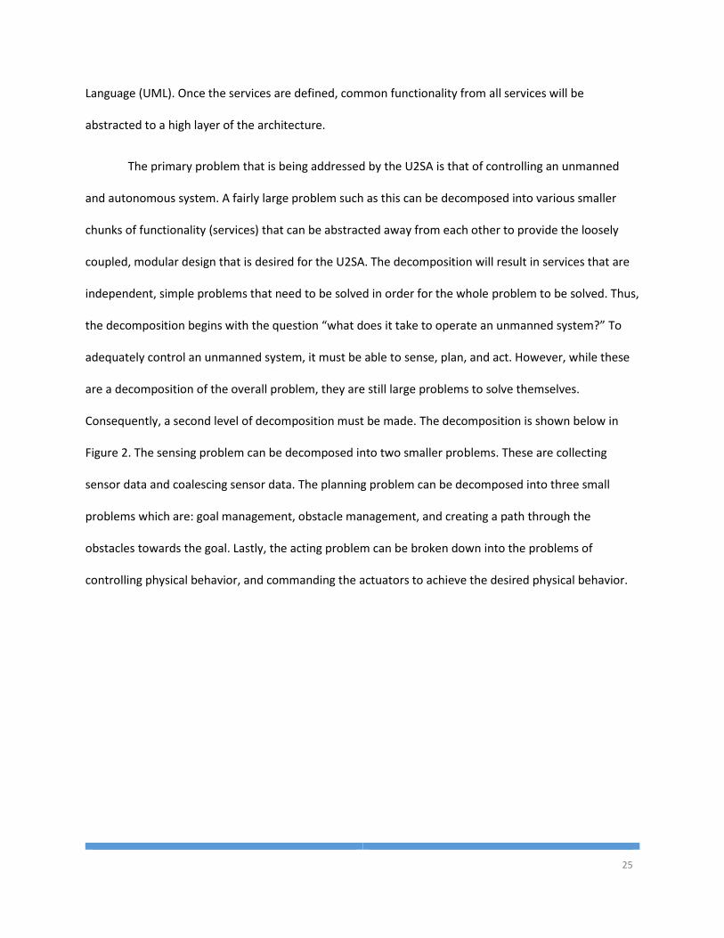
Consequently, a second level of decomposition must be made. The decomposition is shown below in
Figure 2. The sensing problem can be decomposed into two smaller problems. These are collecting
sensor data and coalescing sensor data. The planning problem can be decomposed into three small
problems which are: goal management, obstacle management, and creating a path through the
obstacles towards the goal. Lastly, the acting problem can be broken down into the problems of
controlling physical behavior, and commanding the actuators to achieve the desired physical behavior.
26
Unmanned System
Sense
Collect Sensor Data
Coalesce Sensor Data
Plan
Goal Management
Obstacle Management
Path Planning
Act
Control System
Actuator Control
Figure 2: Component Breakdown
From this, a collection of services can be identified. Breaking down the diagram further, there
are 5 core services that are integral to the operation of the system. These core services can be
implementation independent and created for one application and shared with another. There are also
two services that would need to be implemented independently for each type of device that they are
connecting to. For this reason, they are considered abstract services as the U2SAS will only provide the
basic outline for these services and they must be implemented further for each individual application.
The 5 core services are State Estimator, Mission Management, World Modeling, Path Planning, and the
Control System. The 2 abstract services are Sensor and Actuator. Each of the services that are required
are described below.
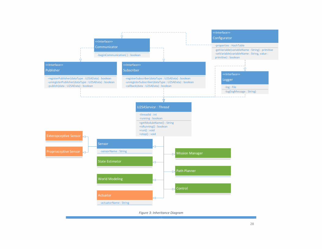
In addition to these 7 services, there are certain interfaces that each service must implement.
Each service must be able to communicate with the other services. The ideal way for services to
communicate asynchronously without increasing coupling is a publisher/subscriber framework. For the
27
logical architecture, the publisher and subscriber interfaces need to be defined; while the other aspects
of inter-process communication will be discussed below in section 3.4 Process Architecture. Pursuant to
user stories 5 and 6, each service must also implement a configuration interface and a logging interface.
The services and interfaces that are defined in the logical architecture are shown below in Figure 3.
Also included in the logical architecture are the data models for the messages that are passed
between the services. To be a complete architecture, the U2SA must define the sets of data that are
communicated in between services through the publisher/subscriber framework. The common features
of a data message will ab abstracted into a U2SA Data class and then each data model will extend and
add fields and functionality to the U2SA Data class.
28
<<Interface>>
Publisher
-registerPublisher(dataType : U2SAData) : boolean
U2SAService : Thread
<<Interface>>
Subscriber
-registerSubscriber(dataType : U2SAData) : boolean
Sensor
State Estimator
Mission Manager
World Modeling
Path Planner
Control
+isRunning() : boolean+run() : void+stop() : void
-callback(data : U2SAData) : boolean
-threadId : int-running : boolean
+getModuleName() : String
<<Interface>>
Configurator
-getVariable(variableName : String) : primitive
<<Interface>>
Logger
-log(logMessage : String)
-log : File
-properties : HashTable
-unregisterSubscriber(dataType : U2SAData) : boolean
Exteropceptive Sensor
Proprioceptive Sensor
<<Interface>>
Communicator
-beginCommunication( ) : boolean
-publish(data : U2SAData) : boolean-unregisterPublisher(dataType : U2SAData) : boolean
Actuator
-setVariable(variableName : String, value : primitive) : boolean
-sensorName : String
-actuatorName : String
Figure 3: Inheritance Diagram
29
3.2.1 Service Interfaces
The service interfaces are designed to meet the standard service contract. The standard service
contract outlines the functionality that every service in the system should implement. Interfaces do not
contain implementations, only definitions of the functionality that needs to be implemented in a service
that claims to implement that interface. All of the interfaces in this section must be implemented in a
service to be U2SA compliant.
3.2.1.1 Configurator
The Configurator interface is the highest level entity in the U2SA. Every class and service in U2SA
implements the Configurator interface. This interface will define the functionality that will allow services
to read variables and parameters from a configuration text or xml file on the system and utilize those
variables during execution. In many languages it is important to distinguish between different types of
variables. A configuration file for the U2SA must not only specify the name and value of a variable, but
also the type of the variable so that the configurator can correctly parse the variable and the services
can identify how to use the variable in their implementation.
Parameters
The configurator itself cannot implement its own functionality, therefore it doesn’t have a
configuration file. Thus, properties that are necessary for configuration must be specified as constants in
the Configurator class.
Definitions
getVariable(variableName : String) : primitive
This function will allow the classes and services to retrieve a primitive data type from the
configuration hash table. The function will return a primitive value of type integer, double,
30
Boolean, or String. How the hash table and properties file works will be language dependent,
and thus the type of the return will be implementation specific.
setVariable(variableName : String, value : primitive) : Boolean
The set variable function is used to update variables in the hash table. After updating the table,
the new values should be written to the configuration file to ensure variable persistence. The
function will return a Boolean value that is true if the table was successfully updated and written
to file and false if an error occurred during this process. If false is returned, the service should
write the error to the log file using the logger interface.
enumerateFields() : ArrayList<[String, primitive]>
Every service module that implements the configurator must have the ability to broadcast a list
of the internal fields that can be set remotely by another process or service. This will allow a
user to collect the list of configuration variables and view their current values, and make the
best decisions during tuning about which fields to alter.
3.2.1.2 Communicator
The communicator interface will define the data variable and functionality that is required to
communicate with the other services in the system. The communication management system is
described below in section 3.4 Process Architecture. If network ports are used, the communicator
interface will have a socket variable. If shared memory is being used, the communicator should contain
a shared memory reference variable.
Parameters
This interface will implement the configurator interface which will allow the Communicator
interface to get service variables from the service properties file. Any properties that are required for
communicating with the system services can go in the configuration properties file for the service.
31
Definitions
beginCommunication( ) : Boolean
This interface will provide a default implementation of the begin communication function. This
function will set up any class variables that are required for communicating with the system
services. This function will open any ports, or set up memory buffers, etc. that are necessary for
communication
3.2.1.3 Publisher
The Publisher interface will specify the functionality that is required to broadcast messages to
any other services in the system that are listening for the type of data that the service is transmitting.
Parameters
This interface will implement the configurator interface which will allow the Publisher interface
to get service variables from the service properties file. Any properties that are required for publishing
on the communication channel can go in the configuration properties file.
Definitions
registerPublisher(dataType : U2SAData.class) : Boolean
Any class implementing the publisher interface will have the register publisher function which
a class will call on itself during instantiation. This function will initiate communication with the
communication manager and register itself as a publisher of the U2SA Data class. This function
will return a Boolean result that is true if the registration was successful or false if the service
was not able to register with the communication manager.
unregisterPublisher(dataType : U2SAData.class) : Boolean
This function will communicate with the communication manager and remove itself from list
of broadcasters. This function will return a Boolean result that is true if the service successfully
32
removed itself from the broadcaster list and false if the communication with the
communication manager was unsuccessful.
publish(data : U2SAData) : Boolean
Published messages that are the U2SA Data type will automatically be passed to services that
are listening for that data type. The return value will be a Boolean value that is true if the
message was successfully published onto the communication channel and false if the
communication channel failed to broadcast the message.
3.2.1.4 Subscriber
The Subscriber interface includes the functionality that is required to receive messages from
other services in the system that are broadcasting the type of data that the service is listening for.
Parameters
This interface will implement the configurator interface which will allow the Subscriber interface
to get service variables from the service properties file. Any properties that are required for subscribing
to the communication channels can go in the configuration properties file.
Definitions
registerSubscriber(dataType : U2SAData.class) : Boolean
Classes that implement subscriber must have the register subscriber function which a class will
call on itself at the time of instantiation. This function communicates to the communication
manager and registers itself as a listener for the U2SA Data type that is passed to this function.
The return value will be a Boolean result that is true if the registration was successful or false if
the service was not able to register with the communication manager.
unregisterSubscriber(dataType : U2SAData.class) : Boolean
33
This function will communicate with the communication manager and remove itself from list of
listeners for the type of U2SA Data that is passed to this function. The return will be a Boolean
result that is true if the service successfully removed itself from the listeners list and false if the
communication with the communication manager was unsuccessful.
3.2.1.5 Logger
The Logger interface provides the default logging functionality that all services require. The
default logging functionality will allow all U2SA services across the system to have a standard logging
format for easy reading and post-mission analysis.
Parameters
This interface will implement the configurator interface which will allow the Logger interface to
get service variables from the service properties file. Any properties that are required for logging
information can go in the configuration properties file. Property variables that should exist in the
properties file should include the highest level of logging to write to file and the path to where the log
file will be written.
Definitions
log(level : LogLevelEnum, logMessage : String) : void
The log interface provides a function for logging a string message with a certain priority level.
The LogLevelEnum should include the following levels: debug, info, warn, and error. More levels
can be added if necessary. When called, the default implementation should first check to see if
the log file for the service already exists; if not, it should create the file. It should then open the
file, write a time stamp, the log level, and the log message string to the file in a new line. If
memory in the system is not a concern, it should keep the file open for quicker writing, but flush
the file after each call to the log function.
34
3.2.2 Abstract Services
The abstract services are classes in the system that do not actually run. They only provide
implementations and datasets that are required by all of the classes in the system that are of that type.
The largest abstract class is the U2SA Service class which implements all of the interfaces listed above
and thus provides the service contract for the U2SA. The other abstract classes, sensor and actuator,
must implement the common functionality for those types of software modules. For example, if all
sensors need to have a unique name, the variable should be defined in the Sensor class and the method
for populating that field should be implemented in the Sensor class. This way, developers of a sensor
service will be able to use the same variable name between services and the implementation is
abstracted from the service developer. The abstract classes that still need to be implemented further
are shown in orange on the above Figure 3.
3.2.2.1 U2SA Service
The U2SA Service class is an abstract class that specifies the service contract that all services in the
system must abide by. By implementing the service contract functions in the U2SA class, all subclasses of
the U2SA will have the same functionality and thus, making changes to the service contract can be made
easily in the U2SA Service class and those changes will be propagated to all of the services in the system.
The U2SA service implements a number of interfaces that are described above. However, there are
a number of additional functions that must be implemented by every service to conform to the service
contract. These functional pieces include:
Discovery – At instantiation, the U2SA service will subscribe to a communication channel for service
discovery. When a new discover message is received by the service, it should respond to the
discovery request with a discovery response that includes the service name, the service type, and
the service status. This will allow U2SA services to find all the other services in the system and
35
determine what modules are available. Also, the discovery services could be used as a heartbeat to
determine if services are still alive.
Functionality Discovery – After a service is aware of other services, it may be necessary to figure out
what functionality that service provides. On the same discovery channel, a service could request a
specific service to enumerate the data channels that it publishes and subscribes to. This would allow
for truly robust data communication. Instead of coupling two independent services by making them
talk only to each other, this would let service A find a service B that publishes the type of data that
service A is looking for without service A needing to know anything about service B.
Stop – At Instantiation, the U2SA service should subscribe to a communication channel for stop
commands. A stop command will have a flag for specifying all services in the system, or just one
service enumerated by name. If the stop all flag is not set, then the stop command must specify a
service by its name which can be found through the discovery interface. When a stop command is
received the service should stop looping and close all of its resources. This will allow the user to
implement a single publishing service to stop all of the services in the system, or just select services.
Configuration Enumeration – In order to easily configure a service remotely, each service must
implement a configuration enumeration interface. When the U2SA service is instantiated, it should
subscribe to a configuration enumeration communication channel. A configuration enumeration
request is published to this channel that includes a service name. The service with that name will
respond with the list of all variables in its configurator and their current value. Ideally, this will be
done by a user interface that can then list all of the configuration variables for the user to change
Configuration Change – After the configuration enumeration, a user may want to change one of the
configuration variables. Therefore, a U2SA service must subscribe to a configuration change
communication channel. A configuration change message must include the name of the service with
the variable that will be changed, the name of the variable, and the new value. When a U2SA service
36
receives a configuration change message, the variable will be updated in the configurator and saved
to the configuration file to ensure persistence.
Parameters
Any properties that are required for all U2SA Services will go in the configuration properties file.
The only globally required attribute for sensors in the U2SA is the service name.
Inputs
A standard U2SA Service will have a number of different inputs. Those specified in this U2SA
document are: discovery requests, stop commands, configuration enumeration requests, and
configuration change requests.
Outputs
The outputs from a U2SA service will include: discovery responses that include the service name,
type, and status, and configuration enumeration responses that contain the service variables and their
current values.
3.2.2.2 Sensor
The Sensor services can take one of two forms: a proprioceptive sensor or an exteroceptive
sensor. These two different subclasses of the Sensor class are defined separately below.
Parameters
Any properties that are required for sensing can go in the configuration properties file. The only
globally required attribute for sensors in the U2SA is the sensor name. Since the State Estimator
subscribes to messages by data type, the State Estimator will receive all state information messages
through the same interface. Sensors must include their unique name in the state information message
37
so that the state estimator can process the data appropriately based on which sensor is the originator of
the message.
Inputs
Sensor objects have an external connection to a sensor through some digital medium like serial,
I2C, SPI, TCP, UDP, etc. The sensor service is responsible for reading the data in from the sensor and
processing the data into a U2SA format that can be transmitted to other services.
Outputs
A Sensor service will output a stream of either State Information data or a stream of object
descriptions depending on which Sensor subclass it extends.
3.2.2.3 Exteroceptive Sensor
An Exteroceptive Sensor service will collect data from the environment and process that data
into zero or more object description messages. An exteroceptive sensor can collect data from a device
like a laser range finder and group data points into object descriptions and send those object
descriptions down the pipe to the World Modeler. Alternatively, the service could collect data from the
sensor and pass each laser data point as a separate object description. The amount of pre-processing
that is done will be implementation specific and is left up to the developers.
Parameters
Any properties that are required for exteroceptive sensing can go in the configuration properties
file. No globally recognized exteroceptive sensor variables are specified in the U2SA.
Inputs
Inputs will be sensor streams through proprietary formats over various types of communication
mediums. The Exteroceptive Sensor service is responsible for defining the variables and making
38
connections with external devices over TCP, UDP, Serial, or some other digital interface. Once
communication is established, the Exteroceptive Sensor will utilize the channel to collect and process
the data coming from the sensor.
Outputs
Once the Exteroceptive Sensor service has processed the data stream and identified the objects
that need to be mapped, it will output an Object Description messages for each object in the field of
view and the frame of reference that is relevant to the current tasks.
3.2.2.4 Proprioceptive Sensor
A Proprioceptive Sensor service will collect data from the system itself and process that data
into state information messages. A proprioceptive sensor service will collect data from a device like a
GPS or IMU, populate the necessary fields in a state information message, and send the state
information down the pipe to the state estimator for further filtering and analysis.
Parameters
Any properties that are required for proprioceptive sensing can go in the configuration
properties file. No globally recognized proprioceptive sensor variables are specified in the U2SA.
Inputs
Inputs will be sensor streams through proprietary formats over various types of communication
mediums. The Proprioceptive Sensor service is responsible for defining the variables and making
connections with external devices over TCP, UDP, Serial, or some other digital interface. Once
communication is established, the Proprioceptive Sensor will utilize the channel to collect and process
the data coming from the sensor.
39
Outputs
Outputs will be state information messages. The state information message is defined below in
section 3.2.3 Messaging Data Models. As not all sensors have data for all dimensions of the state
information, only state information fields that are collected by the sensor should be set to values to
conserve bandwidth and make it easier to process at the State Estimator.
3.2.2.5 Actuator
An actuator service will provide an interface to a real-world physical device that can change the
state of the system or the environment. In order to make the U2SA as broadly applicable as possible, the
different types of actuators and the data that is required to command them are not specified in this
architecture. The actuator class must be extended for each type of actuator and interface that the
system uses.
Parameters
Any properties that are required for all types of actuators can go in the configuration properties
file. The only globally required attribute for actuators in the U2SA is the actuator name. Since the
Control System publishes messages by data type, all actuators will receive all actuator commands.
Actuators services should only execute on actuator messages that are specified for them by using their
unique name specified in the configuration file.
Inputs
The inputs for an actuator service will contain actuator commands from the control system. The
Actuator commands will be addressed to a specific actuator using the Actuator name. Each actuator
must check the actuator name field and only process the command if it is addressed to itself.
40
Outputs
Outputs from this service will be proprietary messages over some digital medium. The outputs
will be dependent on the type of actuator, the manufacturer, and the function and range of the
actuator.
3.2.3 Core Services
The Core Services are those services that are required on every U2SA system. The core services
are the services that were derived above in the functional breakdown of the unmanned system
problem. They are shown in green in the above Figure 3. These services will be executable threads that
will run in an implementation of the U2SA.
3.2.3.1 State Estimator
The State Estimator accepts state information from the various Proprioceptive Sensor services in
the system. When new data comes in from one of the sensors, the State Estimator will calculate the best
estimate for the state of the system. The state of the system includes the location, rotation, speed, and
acceleration of the system, as well as the speed through the fluid, like airspeed or speed through the
current in water.
Parameters
Any necessary parameters for a state estimation algorithm should be specified through the
configurator interface file.
Inputs
The inputs for the State Estimator come from the Proprioceptive Sensor services in the system.
The messages from the proprioceptive sensors will include some subset of the state information data,
which subset is specified by a presence vector in the data message. The State Estimator will extract the
41
data from the message for the fields specified by the presence vector and filter the new data with
previous data from the same sensor and data from other sensors to create the best estimate.
Outputs
The output of the State Estimator is the best estimate of the state of the system. After receiving
data from the sensors, the State Estimator will filter the data and combine the data from the different
sensors to create the best estimate and transmit that information over the communication channel so
that other services can receive the current state of the system.
3.2.3.2 Mission Manager
The Mission Manager is responsible for maintaining a list of goals and completion criteria for the
task that the system is assigned to accomplish. Goals can be specified as location/attitude/time
waypoints, sensor objectives, or custom tasks.
Parameters
Any necessary parameters for mission management should be specified through the
configurator interface file. The mission information like waypoints, objects, thresholds, etc. will be
specified in terms of an XML file. The XML entries will have the name of a class of a goal object, like
“Waypoint”. The Goal Object and a couple of basic Goal Object extensions are described below in
section 3.2.3 Messaging Data Models. Inside of the class tag there will be tags for each of the fields that
are necessary to build a Goal Description object of that type. Any additional Goal Description classes
that are made as an extension need to be document such that the Mission Manager can parse the
information and build an object from the XML mission description file. For example, one entry in the
XML file might be a Waypoint. Inside of that Waypoint XML entry will be the Unique Identifier (UID) of
the goal, the reference frame of the waypoint, and at least one of the dimensions that are specified in
the Waypoint class. An example waypoint XML is shown below:
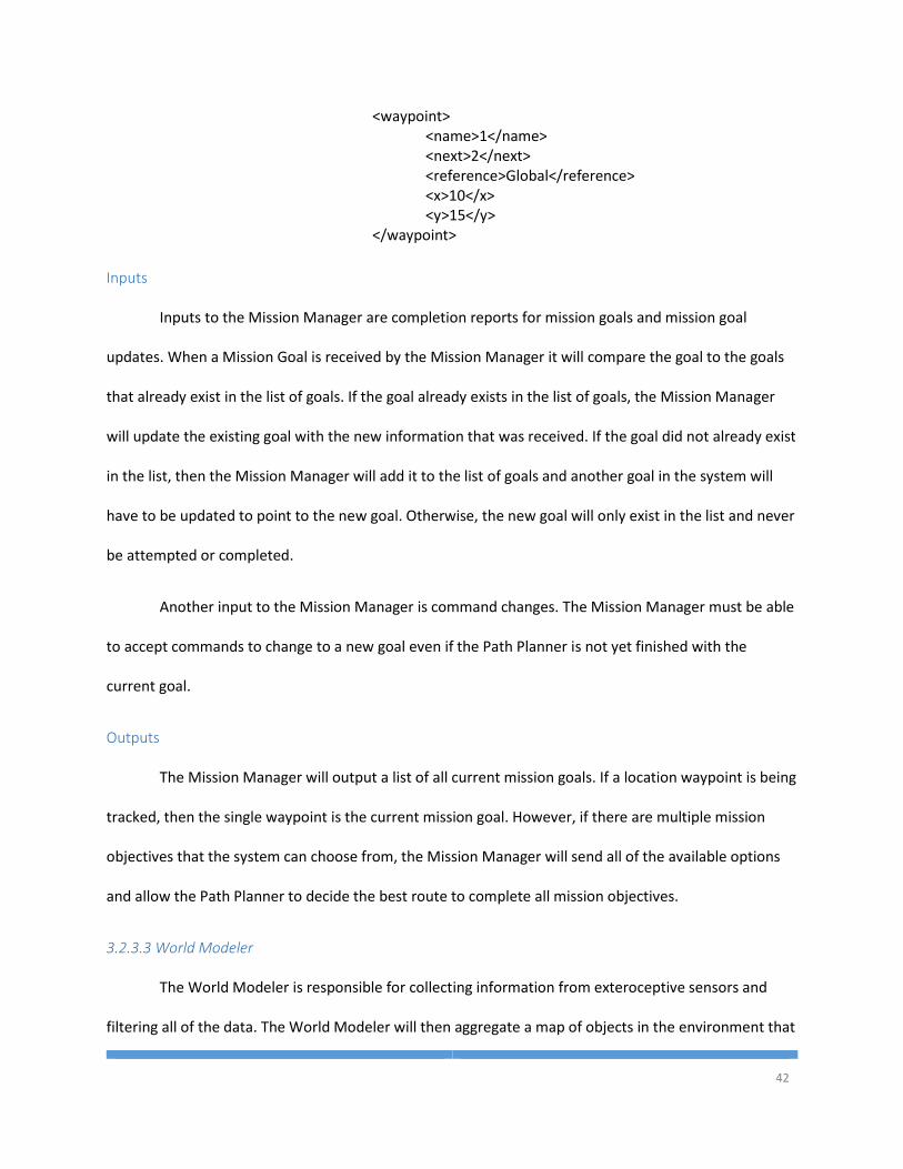
42
<waypoint> <name>1</name> <next>2</next>
<reference>Global</reference> <x>10</x> <y>15</y> </waypoint>
Inputs
Inputs to the Mission Manager are completion reports for mission goals and mission goal
updates. When a Mission Goal is received by the Mission Manager it will compare the goal to the goals
that already exist in the list of goals. If the goal already exists in the list of goals, the Mission Manager
will update the existing goal with the new information that was received. If the goal did not already exist
in the list, then the Mission Manager will add it to the list of goals and another goal in the system will
have to be updated to point to the new goal. Otherwise, the new goal will only exist in the list and never
be attempted or completed.
Another input to the Mission Manager is command changes. The Mission Manager must be able
to accept commands to change to a new goal even if the Path Planner is not yet finished with the
current goal.
Outputs
The Mission Manager will output a list of all current mission goals. If a location waypoint is being
tracked, then the single waypoint is the current mission goal. However, if there are multiple mission
objectives that the system can choose from, the Mission Manager will send all of the available options
and allow the Path Planner to decide the best route to complete all mission objectives.
3.2.3.3 World Modeler
The World Modeler is responsible for collecting information from exteroceptive sensors and
filtering all of the data. The World Modeler will then aggregate a map of objects in the environment that
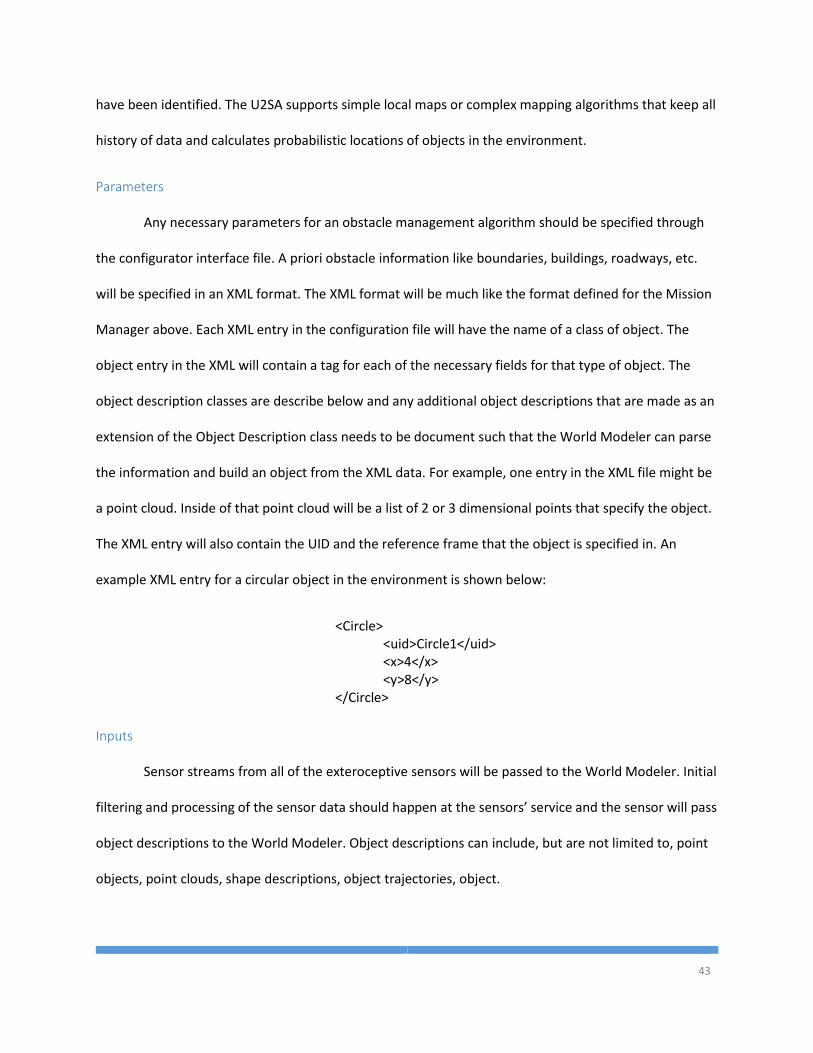
43
have been identified. The U2SA supports simple local maps or complex mapping algorithms that keep all
history of data and calculates probabilistic locations of objects in the environment.
Parameters
Any necessary parameters for an obstacle management algorithm should be specified through
the configurator interface file. A priori obstacle information like boundaries, buildings, roadways, etc.
will be specified in an XML format. The XML format will be much like the format defined for the Mission
Manager above. Each XML entry in the configuration file will have the name of a class of object. The
object entry in the XML will contain a tag for each of the necessary fields for that type of object. The
object description classes are describe below and any additional object descriptions that are made as an
extension of the Object Description class needs to be document such that the World Modeler can parse
the information and build an object from the XML data. For example, one entry in the XML file might be
a point cloud. Inside of that point cloud will be a list of 2 or 3 dimensional points that specify the object.
The XML entry will also contain the UID and the reference frame that the object is specified in. An
example XML entry for a circular object in the environment is shown below:
<Circle> <uid>Circle1</uid>
<x>4</x> <y>8</y> </Circle>
Inputs
Sensor streams from all of the exteroceptive sensors will be passed to the World Modeler. Initial
filtering and processing of the sensor data should happen at the sensors’ service and the sensor will pass
object descriptions to the World Modeler. Object descriptions can include, but are not limited to, point
objects, point clouds, shape descriptions, object trajectories, object.
44
Outputs
The World Modeler will output a list of object descriptions that are relevant to the mission
tasks. To reduce dependency between services, multiple streams can be published if different data is
needed at different times in a mission and listeners of these streams can subscribe and unsubscribe as
needed.
3.2.3.4 Path Planner
The Path Planner is fundamentally a state machine that will change state based on current
mission goals. Each state will represent a different type of mission goal and contain the logic that is
required to complete that task given the filtered sensor data streams. For systems that have subsystems
like arms or other manipulators, the Path Planner must generate navigation points for each of the
subsystems that must move for the current task.
Parameters
Any necessary parameters for an obstacle management algorithm should be specified through
the configurator interface file.
Inputs
The Path Planner will take in filtered state information streams from the state estimator module
and filtered object descriptions from the world modeler. It will also accept mission information streams
from the mission manager.
Outputs
Output streams will be in the form of navigation commands, which are defined below in the
messaging models, in the local frame to the control system module. The Path Planner will also output a
mission information stream that will be used to alert the Mission Manager of completed tasks and goals.
45
3.2.3.5 Control System
The Control System service will calculate the actuator commands from the drive point generated
by the Path Planner. Ideally, the Control System will discover which actuators exist in the system, the
extents that the actuators can go to, and how those actuators influence the state of the system. While
this could be done with the U2SA, it is also possible to abstract the actuator commands to a 0-100%
range and implement the actuator services to interpret that percentage in the way makes sense for that
actuator such as angle, speed, distance, etc.
Parameters
Any necessary parameters for an obstacle management algorithm should be specified through
the configurator interface file.
Inputs
The control system will accept navigation points in the local frame from the path planner for the
different subsystems of the unmanned system.
Outputs
The output from the control system will be a stream of actuator commands. The actuator
commands will have a range from -100-100% and the name of the actuator that should receive the
command. The output stream will be a software communication bus on which all actuator services will
receive all actuator commands and only parse the commands that are addressed to that actuator
services’ name.
3.2.3 Messaging Data Models
There are many services in the U2SA that need to communicate with each other. In order to
guarantee communication between two separate modules, both modules must have the same data
model. The data models specified here can be added to or adapted for different applications because
46
the U2SA does not define a standard communication protocol for all system interoperability. There are
plenty of solutions out there for system interoperability communication protocols like JAUS, STANAG
4586, or MAVLink.
The messages that are specified in the U2SA data model include the State Information, Goal
Information, Object Description, Navigation Point, and Actuator Command messages. The services that
utilize these messages are shown below in Figure 4 where blue modules represent services and green
modules represent message classes. Each message class must also be serializable so that the message
object can be turned into a byte array and sent over various communication channels. Thus, each
message class must extend the U2SA Data abstract class.
By making services not dependent on each other, but on the information that is transmitted
between them, a robust and lowly coupled dependency architecture is created within the U2SA. This
data model dependency is ideal because it allows any service module to be easily replaced by a
completely different service that broadcasts the same data model. Developers can then create and use
software in the loop or hardware in the loop simulators much more easily than having a separate full
system implementation for simulation. This type of dependency also allows developers to add new fields
and information to the data flow, or modify existing data models, in a single central location.
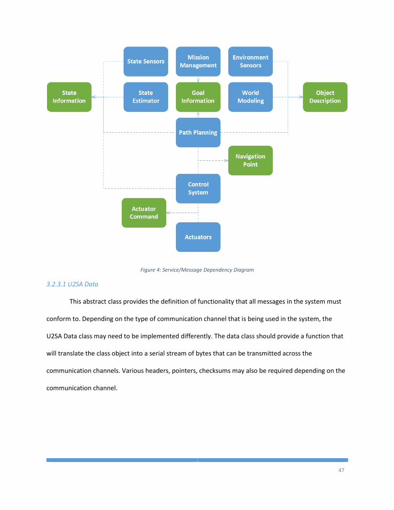
47
Figure 4: Service/Message Dependency Diagram
3.2.3.1 U2SA Data
This abstract class provides the definition of functionality that all messages in the system must
conform to. Depending on the type of communication channel that is being used in the system, the
U2SA Data class may need to be implemented differently. The data class should provide a function that
will translate the class object into a serial stream of bytes that can be transmitted across the
communication channels. Various headers, pointers, checksums may also be required depending on the
communication channel.
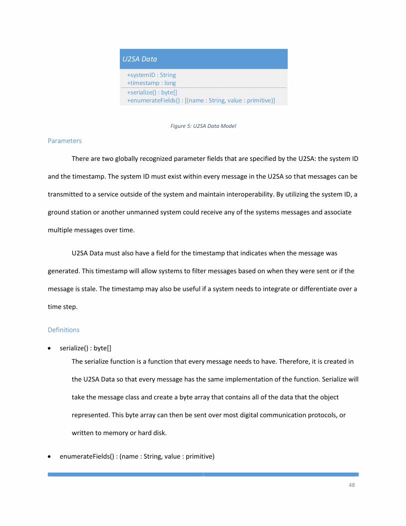
48
U2SA Data
+serialize() : byte[]+enumerateFields() : [(name : String, value : primitive)]
+systemID : String+timestamp : long
Figure 5: U2SA Data Model
Parameters
There are two globally recognized parameter fields that are specified by the U2SA: the system ID
and the timestamp. The system ID must exist within every message in the U2SA so that messages can be
transmitted to a service outside of the system and maintain interoperability. By utilizing the system ID, a
ground station or another unmanned system could receive any of the systems messages and associate
multiple messages over time.
U2SA Data must also have a field for the timestamp that indicates when the message was
generated. This timestamp will allow systems to filter messages based on when they were sent or if the
message is stale. The timestamp may also be useful if a system needs to integrate or differentiate over a
time step.
Definitions
serialize() : byte[]
The serialize function is a function that every message needs to have. Therefore, it is created in
the U2SA Data so that every message has the same implementation of the function. Serialize will
take the message class and create a byte array that contains all of the data that the object
represented. This byte array can then be sent over most digital communication protocols, or
written to memory or hard disk.
enumerateFields() : (name : String, value : primitive)
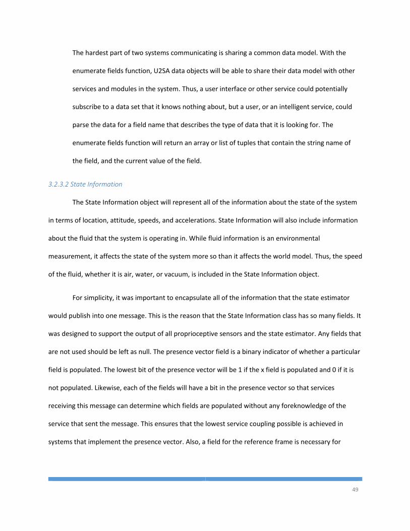
49
The hardest part of two systems communicating is sharing a common data model. With the
enumerate fields function, U2SA data objects will be able to share their data model with other
services and modules in the system. Thus, a user interface or other service could potentially
subscribe to a data set that it knows nothing about, but a user, or an intelligent service, could
parse the data for a field name that describes the type of data that it is looking for. The
enumerate fields function will return an array or list of tuples that contain the string name of
the field, and the current value of the field.
3.2.3.2 State Information
The State Information object will represent all of the information about the state of the system
in terms of location, attitude, speeds, and accelerations. State Information will also include information
about the fluid that the system is operating in. While fluid information is an environmental
measurement, it affects the state of the system more so than it affects the world model. Thus, the speed
of the fluid, whether it is air, water, or vacuum, is included in the State Information object.
For simplicity, it was important to encapsulate all of the information that the state estimator
would publish into one message. This is the reason that the State Information class has so many fields. It
was designed to support the output of all proprioceptive sensors and the state estimator. Any fields that
are not used should be left as null. The presence vector field is a binary indicator of whether a particular
field is populated. The lowest bit of the presence vector will be 1 if the x field is populated and 0 if it is
not populated. Likewise, each of the fields will have a bit in the presence vector so that services
receiving this message can determine which fields are populated without any foreknowledge of the
service that sent the message. This ensures that the lowest service coupling possible is achieved in
systems that implement the presence vector. Also, a field for the reference frame is necessary for
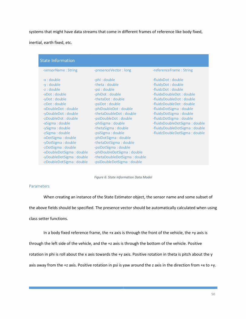
50
systems that might have data streams that come in different frames of reference like body fixed,
inertial, earth fixed, etc.
State Information
-x : double-y : double-z : double-xDot : double
-zDot : double-yDot : double
-xDoubleDot : double
-zDoubleDot : double-yDoubleDot : double
-xSigma : double-ySigma : double-zSigma : double-xDotSigma : double
-zDotSigma : double-yDotSigma : double
-xDoubleDotSigma : double
-zDoubleDotSigma : double-yDoubleDotSigma : double
-phi : double-theta : double-psi : double-phiDot : double-thetaDot : double-psiDot : double-phiDoubleDot : double-thetaDoubleDot : double-psiDoubleDot : double-phiSigma : double-thetaSigma : double-psiSigma : double-phiDotSigma : double-thetaDotSigma : double-psiDotSigma : double-phiDoubleDotSigma : double-thetaDoubleDotSigma : double-psiDoubleDotSigma : double
-fluidxDot : double-fluidyDot : double-fluidzDot : double-fluidxDoubleDot : double-fluidyDoubleDot : double-fluidzDoubleDot : double-fluidxDotSigma : double-fluidyDotSigma : double-fluidzDotSigma : double-fluidxDoubleDotSigma : double-fluidyDoubleDotSigma : double-fluidzDoubleDotSigma : double
-presenceVector : long-sensorName : String -referenceFrame : String
Figure 6: State Information Data Model
Parameters
When creating an instance of the State Estimator object, the sensor name and some subset of
the above fields should be specified. The presence vector should be automatically calculated when using
class setter functions.
In a body fixed reference frame, the +x axis is through the front of the vehicle, the +y axis is
through the left side of the vehicle, and the +z axis is through the bottom of the vehicle. Positive
rotation in phi is roll about the x axis towards the +y axis. Positive rotation in theta is pitch about the y
axis away from the +z axis. Positive rotation in psi is yaw around the z axis in the direction from +x to +y.
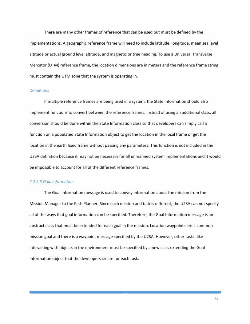
51
There are many other frames of reference that can be used but must be defined by the
implementations. A geographic reference frame will need to include latitude, longitude, mean sea level
altitude or actual ground level altitude, and magnetic or true heading. To use a Universal Transverse
Mercator (UTM) reference frame, the location dimensions are in meters and the reference frame string
must contain the UTM zone that the system is operating in.
Definitions
If multiple reference frames are being used in a system, the State Information should also
implement functions to convert between the reference frames. Instead of using an additional class, all
conversion should be done within the State Information class so that developers can simply call a
function on a populated State Information object to get the location in the local frame or get the
location in the earth fixed frame without passing any parameters. This function is not included in the
U2SA definition because it may not be necessary for all unmanned system implementations and it would
be impossible to account for all of the different reference frames.
3.2.3.3 Goal Information
The Goal Information message is used to convey information about the mission from the
Mission Manager to the Path Planner. Since each mission and task is different, the U2SA can not specify
all of the ways that goal information can be specified. Therefore, the Goal Information message is an
abstract class that must be extended for each goal in the mission. Location waypoints are a common
mission goal and there is a waypoint message specified by the U2SA. However, other tasks, like
interacting with objects in the environment must be specified by a new class extending the Goal
Information object that the developers create for each task.
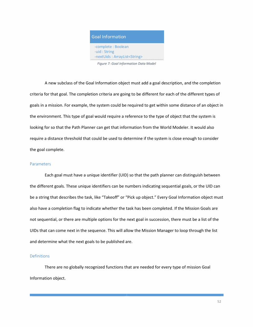
52
Goal Information
-complete : Boolean-uid : String-nextUids : ArrayList<String>
Figure 7: Goal Information Data Model
A new subclass of the Goal Information object must add a goal description, and the completion
criteria for that goal. The completion criteria are going to be different for each of the different types of
goals in a mission. For example, the system could be required to get within some distance of an object in
the environment. This type of goal would require a reference to the type of object that the system is
looking for so that the Path Planner can get that information from the World Modeler. It would also
require a distance threshold that could be used to determine if the system is close enough to consider
the goal complete.
Parameters
Each goal must have a unique identifier (UID) so that the path planner can distinguish between
the different goals. These unique identifiers can be numbers indicating sequential goals, or the UID can
be a string that describes the task, like “Takeoff” or “Pick up object.” Every Goal Information object must
also have a completion flag to indicate whether the task has been completed. If the Mission Goals are
not sequential, or there are multiple options for the next goal in succession, there must be a list of the
UIDs that can come next in the sequence. This will allow the Mission Manager to loop through the list
and determine what the next goals to be published are.
Definitions
There are no globally recognized functions that are needed for every type of mission Goal
Information object.
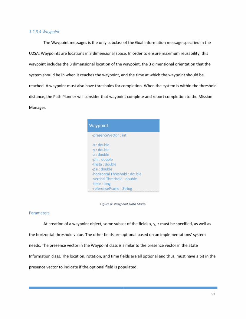
53
3.2.3.4 Waypoint
The Waypoint messages is the only subclass of the Goal Information message specified in the
U2SA. Waypoints are locations in 3 dimensional space. In order to ensure maximum reusability, this
waypoint includes the 3 dimensional location of the waypoint, the 3 dimensional orientation that the
system should be in when it reaches the waypoint, and the time at which the waypoint should be
reached. A waypoint must also have thresholds for completion. When the system is within the threshold
distance, the Path Planner will consider that waypoint complete and report completion to the Mission
Manager.
Waypoint
-x : double-y : double
-theta : double-psi : double
-z : double-phi : double
-time : long
-horizontal Threshold : double-vertical Threshold : double
-referenceFrame : String
-presenceVector : int
Figure 8: Waypoint Data Model
Parameters
At creation of a waypoint object, some subset of the fields x, y, z must be specified, as well as
the horizontal threshold value. The other fields are optional based on an implementations’ system
needs. The presence vector in the Waypoint class is similar to the presence vector in the State
Information class. The location, rotation, and time fields are all optional and thus, must have a bit in the
presence vector to indicate if the optional field is populated.
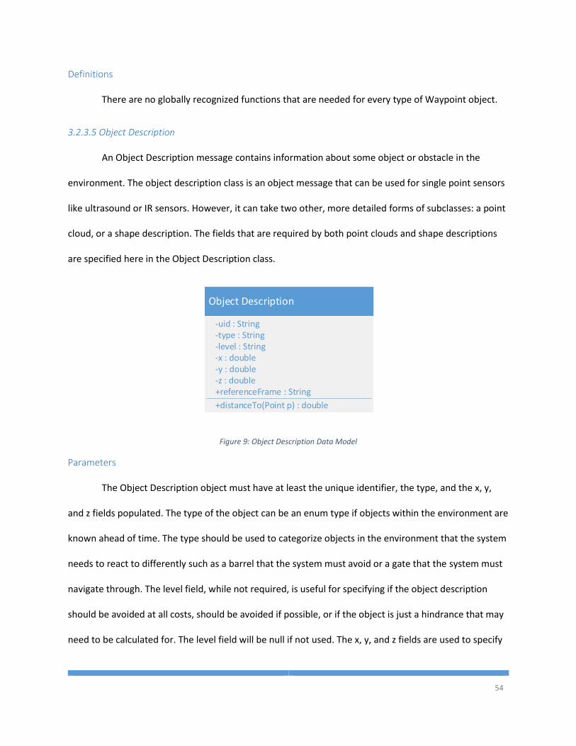
54
Definitions
There are no globally recognized functions that are needed for every type of Waypoint object.
3.2.3.5 Object Description
An Object Description message contains information about some object or obstacle in the
environment. The object description class is an object message that can be used for single point sensors
like ultrasound or IR sensors. However, it can take two other, more detailed forms of subclasses: a point
cloud, or a shape description. The fields that are required by both point clouds and shape descriptions
are specified here in the Object Description class.
Object Description
-x : double
-z : double-y : double
-uid : String
-level : String-type : String
+distanceTo(Point p) : double
+referenceFrame : String
Figure 9: Object Description Data Model
Parameters
The Object Description object must have at least the unique identifier, the type, and the x, y,
and z fields populated. The type of the object can be an enum type if objects within the environment are
known ahead of time. The type should be used to categorize objects in the environment that the system
needs to react to differently such as a barrel that the system must avoid or a gate that the system must
navigate through. The level field, while not required, is useful for specifying if the object description
should be avoided at all costs, should be avoided if possible, or if the object is just a hindrance that may
need to be calculated for. The level field will be null if not used. The x, y, and z fields are used to specify
55
the center point of the object. These fields are useful for determining if the object is something that the
system needs to take into account when planning a path or if the object is out of the area of interest and
therefore no more processing of that object information is needed.
Definitions
Each of the different subclasses of Object Description will describe shapes differently. Therefore,
each sub-class must implement the function that calculates distance from the parameter, type Point, to
the closest point of the object. This will allow the Path Planner to determine if the closest point of the
object is too close to the path for the system to maneuver around.
Typically, a sensor will report information in the local frame centered at the sensor. If the
systems engineers of a project decide to put the objects into a global reference frame, then the Object
Description message will need to be built in the global reference frame and the message will need to
have a function for converting the global frame into the local frame given the current location of the
vehicle.
3.2.3.6 Point Cloud
A Point Cloud object extends the Object Description message and adds new fields that are useful
for describing an object through an array of points. Point Clouds are a common data format for
exteroceptive sensors like laser range finders or stereovision cameras. A Point object must be specified
with an azimuth, elevation, and distance to the point.
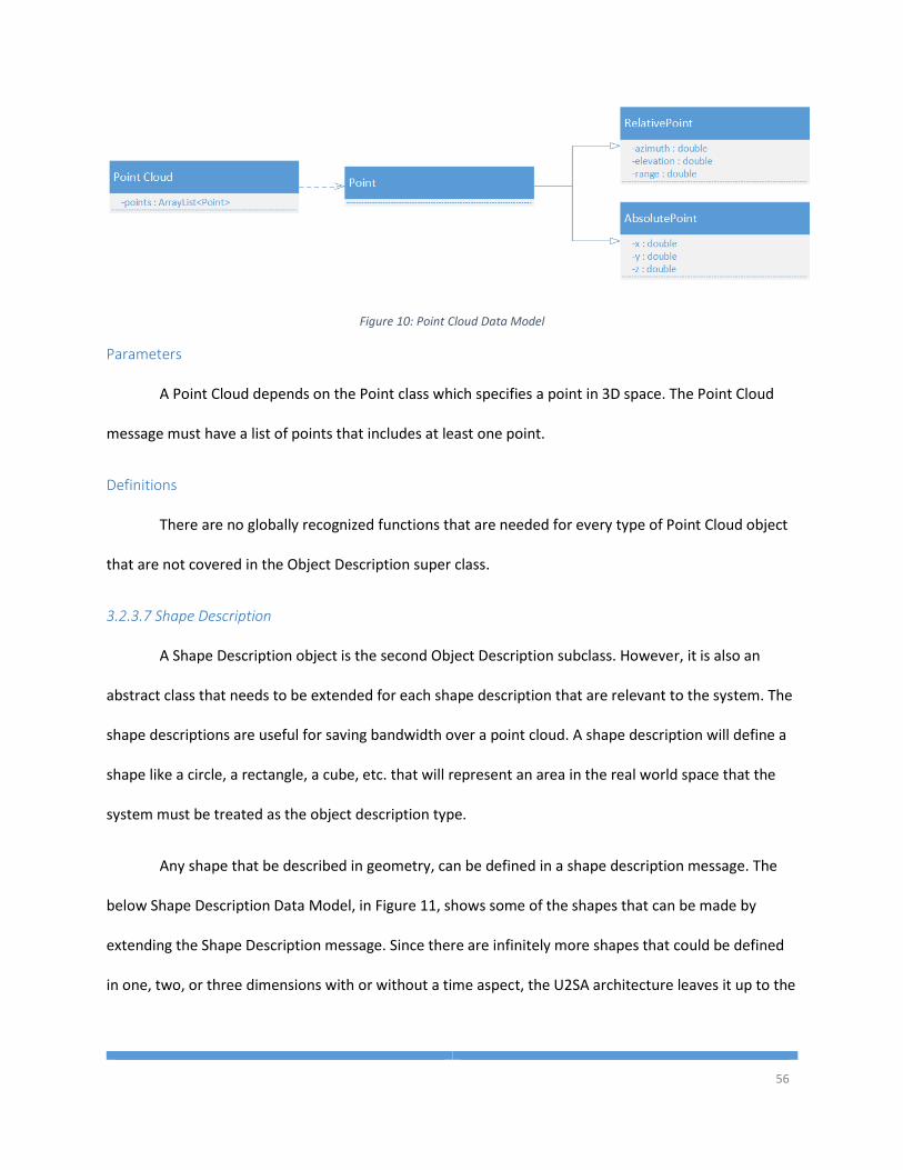
56
Figure 10: Point Cloud Data Model
Parameters
A Point Cloud depends on the Point class which specifies a point in 3D space. The Point Cloud
message must have a list of points that includes at least one point.
Definitions
There are no globally recognized functions that are needed for every type of Point Cloud object
that are not covered in the Object Description super class.
3.2.3.7 Shape Description
A Shape Description object is the second Object Description subclass. However, it is also an
abstract class that needs to be extended for each shape description that are relevant to the system. The
shape descriptions are useful for saving bandwidth over a point cloud. A shape description will define a
shape like a circle, a rectangle, a cube, etc. that will represent an area in the real world space that the
system must be treated as the object description type.
Any shape that be described in geometry, can be defined in a shape description message. The
below Shape Description Data Model, in Figure 11, shows some of the shapes that can be made by
extending the Shape Description message. Since there are infinitely more shapes that could be defined
in one, two, or three dimensions with or without a time aspect, the U2SA architecture leaves it up to the
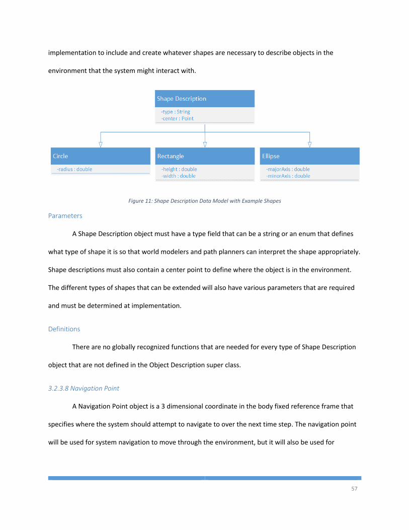
57
implementation to include and create whatever shapes are necessary to describe objects in the
environment that the system might interact with.
Figure 11: Shape Description Data Model with Example Shapes
Parameters
A Shape Description object must have a type field that can be a string or an enum that defines
what type of shape it is so that world modelers and path planners can interpret the shape appropriately.
Shape descriptions must also contain a center point to define where the object is in the environment.
The different types of shapes that can be extended will also have various parameters that are required
and must be determined at implementation.
Definitions
There are no globally recognized functions that are needed for every type of Shape Description
object that are not defined in the Object Description super class.
3.2.3.8 Navigation Point
A Navigation Point object is a 3 dimensional coordinate in the body fixed reference frame that
specifies where the system should attempt to navigate to over the next time step. The navigation point
will be used for system navigation to move through the environment, but it will also be used for
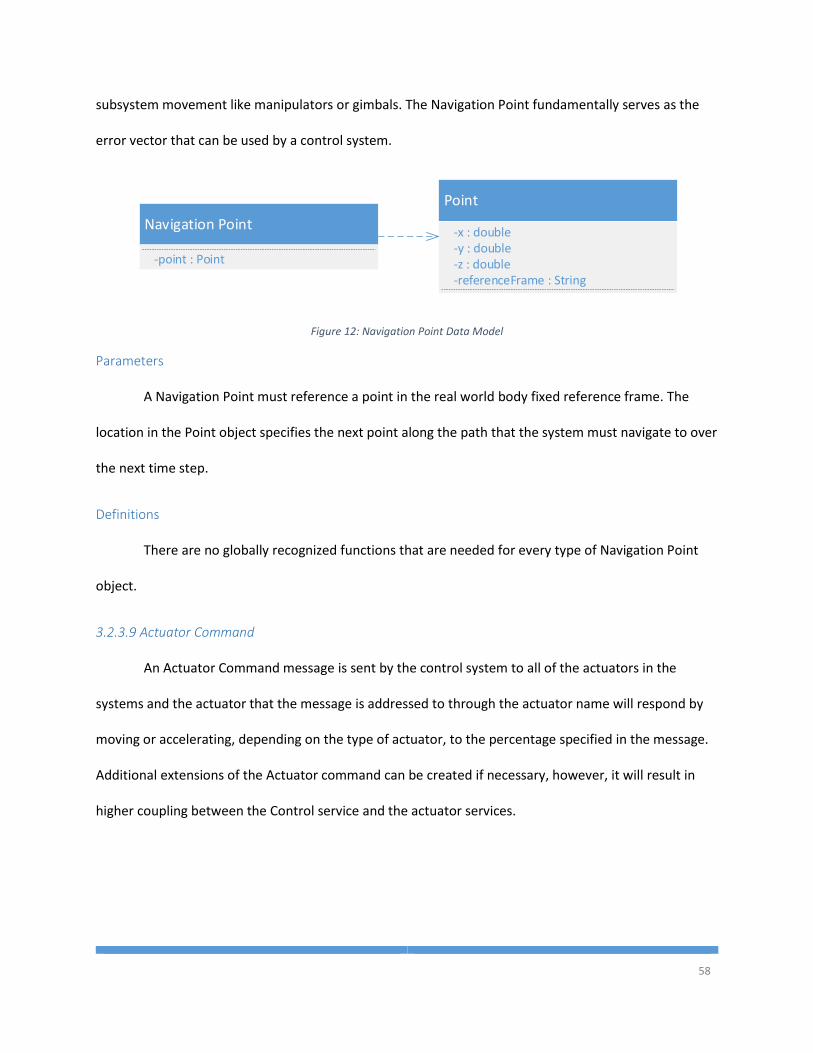
58
subsystem movement like manipulators or gimbals. The Navigation Point fundamentally serves as the
error vector that can be used by a control system.
Navigation Point
-point : Point
Point
-x : double
-z : double-y : double
-referenceFrame : String
Figure 12: Navigation Point Data Model
Parameters
A Navigation Point must reference a point in the real world body fixed reference frame. The
location in the Point object specifies the next point along the path that the system must navigate to over
the next time step.
Definitions
There are no globally recognized functions that are needed for every type of Navigation Point
object.
3.2.3.9 Actuator Command
An Actuator Command message is sent by the control system to all of the actuators in the
systems and the actuator that the message is addressed to through the actuator name will respond by
moving or accelerating, depending on the type of actuator, to the percentage specified in the message.
Additional extensions of the Actuator command can be created if necessary, however, it will result in
higher coupling between the Control service and the actuator services.
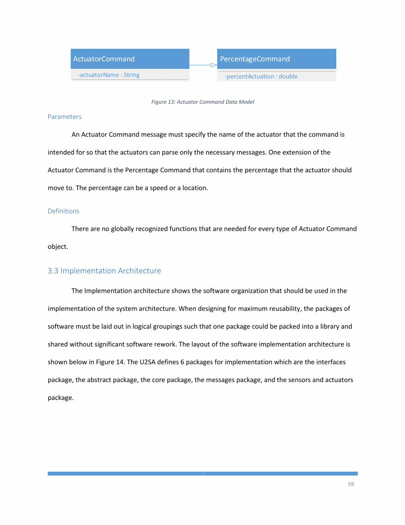
59
ActuatorCommand
-actuatorName : String
PercentageCommand
-percentActuation : double
Figure 13: Actuator Command Data Model
Parameters
An Actuator Command message must specify the name of the actuator that the command is
intended for so that the actuators can parse only the necessary messages. One extension of the
Actuator Command is the Percentage Command that contains the percentage that the actuator should
move to. The percentage can be a speed or a location.
Definitions
There are no globally recognized functions that are needed for every type of Actuator Command
object.
3.3 Implementation Architecture
The Implementation architecture shows the software organization that should be used in the
implementation of the system architecture. When designing for maximum reusability, the packages of
software must be laid out in logical groupings such that one package could be packed into a library and
shared without significant software rework. The layout of the software implementation architecture is
shown below in Figure 14. The U2SA defines 6 packages for implementation which are the interfaces
package, the abstract package, the core package, the messages package, and the sensors and actuators
package.

60
Figure 14: U2SA Package Diagram
Due to the fact that these packages have different implementation independence, the packages
are separated into 4 distinct layers of implementation. The first layer is the most implementation
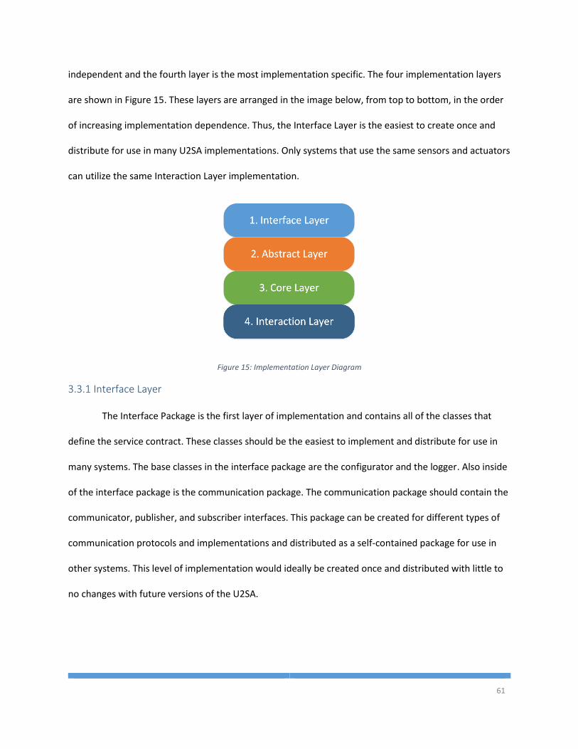
61
independent and the fourth layer is the most implementation specific. The four implementation layers
are shown in Figure 15. These layers are arranged in the image below, from top to bottom, in the order
of increasing implementation dependence. Thus, the Interface Layer is the easiest to create once and
distribute for use in many U2SA implementations. Only systems that use the same sensors and actuators
can utilize the same Interaction Layer implementation.
Figure 15: Implementation Layer Diagram
3.3.1 Interface Layer
The Interface Package is the first layer of implementation and contains all of the classes that
define the service contract. These classes should be the easiest to implement and distribute for use in
many systems. The base classes in the interface package are the configurator and the logger. Also inside
of the interface package is the communication package. The communication package should contain the
communicator, publisher, and subscriber interfaces. This package can be created for different types of
communication protocols and implementations and distributed as a self-contained package for use in
other systems. This level of implementation would ideally be created once and distributed with little to
no changes with future versions of the U2SA.
62
3.3.2 Abstract Layer
The Abstract Layer is the next level of implementation. The Abstract Package should contain the
U2SA service class which implements the service contact for use in all of the subclasses that extend the
U2SA class. It should also contain the abstract sensor and actuator classes to be used when creating new
sensor and actuators services. While only some of the message set is abstract, all of the messaging data
models should be included in the Messages Package within the Abstract Layer because the
communication data models are at a higher level of implementation than the core services. This level of
implementation would be created and distributed with only minor modifications to data models in
future versions.
3.3.3 Core Layer
The Core Layer contains the core services that are required for a U2SA implementation. The
services are the State Estimator, the Mission Manager, the World Modeler, the Path Planner, and the
Control System. Since there are so many different types of algorithms for each of these services, and
they vary widely from a simple system to a complex system, this package will be fairly volatile from one
level of autonomy to another. Each level of perception, intelligence and independence may require a
slightly different implementation of these services which is why they are at level 3 implementation.
However, once an algorithm is implemented using the pre-defined data model of the U2SA, it can easily
be shared and reused across other applications that use the same algorithm.
3.3.4 Interaction Layer
The Interaction Layer contains the packages for interacting with the environment and they are
the most implementation specific. The Sensor and Actuator packages don’t directly define any classes
because they are completely dependent on implementation. These packages should be filled with
extensions of the sensor and actuator abstract classes. Once a sensor or actuator class is created for a
63
specific device that interacts with the environment, it can easily be reused by various applications that
require the same interaction device. However, because every unmanned system and every mission
requires different types of interaction devices, the Sensor and Actuator packages, and the Interaction
Layer of software will be significantly different even though some modules may be shared between
implementations.
3.4 Process Architecture
The Process Architecture shows the different threads of execution of a system and contains
important information about concurrency, reliability, and performance. There are many different ways
that a system can run asynchronously. Concurrency is a field of study all in itself, and is difficult to
express for all current and future systems. For this reason, the Process Architecture must be carefully
designed to allow hard and soft real time systems as well as non-real time systems.
A Process Architecture should specify the communication channels and the medium of
communication. For maximum reusability, a medium of communication is not defined in the U2SA.
There are numerous different software libraries and message oriented middleware packages that can
provide the communication channels required for system operation. A Message Oriented Middleware
(MOM) is a sound solution to the messaging layer by providing a higher level of abstraction and a higher
level of interoperability than an individual messaging implementation. Some example MOMs that could
be used to support the messaging layer are: IBM MQSeries, RTI Data Distribution Service, PeerLogic
Pipes, Qt pipes, Apache ActiveMQ and the messaging of the Robot Operating System.
The data model for the U2SA messages is created above in the Logical Architecture, however,
the Process Architecture must also specify the flow of data in the system. The inputs and outputs of the
services are mapped to communication channels and services that subscribe to the same type of data
that is published by another service create a connection. These connections are necessary for the flow
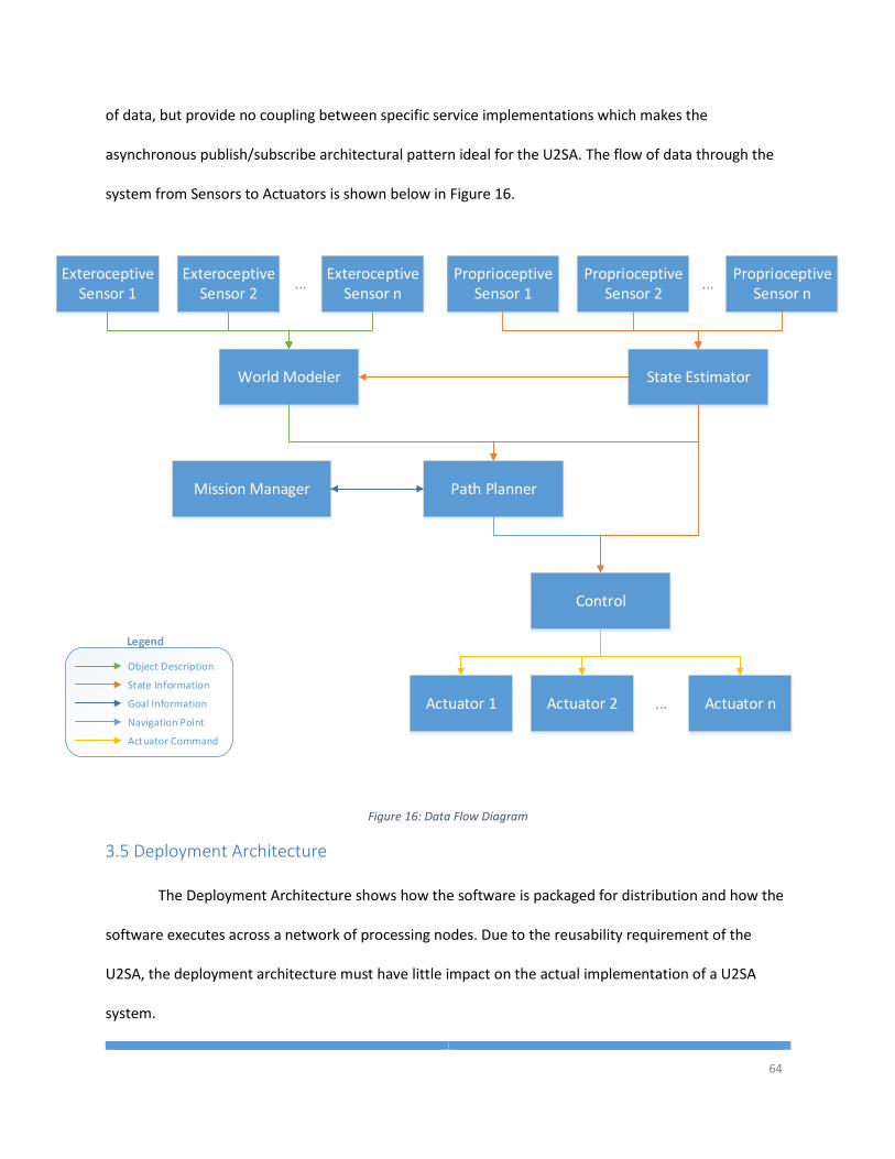
64
of data, but provide no coupling between specific service implementations which makes the
asynchronous publish/subscribe architectural pattern ideal for the U2SA. The flow of data through the
system from Sensors to Actuators is shown below in Figure 16.
Proprioceptive Sensor 1
...
State Estimator
Path PlannerMission Manager
Control
Actuator 1 Actuator 2 Actuator n...
Exteroceptive Sensor 1
...
World Modeler
Exteroceptive Sensor 2
Exteroceptive Sensor n
Proprioceptive Sensor 2
Proprioceptive Sensor n
Object Description
State Information
Goal Information
Navigation Point
Actuator Command
Legend
Figure 16: Data Flow Diagram
3.5 Deployment Architecture
The Deployment Architecture shows how the software is packaged for distribution and how the
software executes across a network of processing nodes. Due to the reusability requirement of the
U2SA, the deployment architecture must have little impact on the actual implementation of a U2SA
system.
65
3.5.1 Packaging
The packaging of the software defines how it should be used to distribute to other users. One of
the biggest advantages to the U2SA is that services can be reused across multiple applications. Thus, the
packaging of the U2SA software will be broken into three types of distribution packages. Each
distribution package will contain some subset of functionality that is required for the U2SA to operate
and allow for maximum reuse across systems. The three types of distribution packages that will be
discussed here are the Template Distribution Package, the Data Model Distribution Package, and the
Individual Service Distribution Package.
3.5.1.1 Template
The first level of packaging in the U2SA must be a Template distribution. This distribution
package should be distributed at an organization level such that organizations that are developing
multiple unmanned systems need to implement this functionality only once and continually reuse it
from one project to the next. The templates will provide the structure and the implementation of
universal interfaces that are required for all of the services in a U2SA system. The Template Distribution
Package will allow developers at the service level to design and create services that are compliant with
an organization wide standard without knowing the lower level details of how the communication
channels, logging, or configuration modules actually operate.
The highest level of implementation abstraction, as shown above in the Implementation
Architecture, are the parts of the U2SA that must be implemented by every service in the system.
However, these interfaces do not provide any useful functionality on their own. In order to encapsulate
a useful template for developers to build on, the Interface Layer and the Abstract Layer outlined in the
Implementation Architecture should be packaged as one distribution package. These packages of
software represent the template that future development should comply with and the templates can
66
then be updated periodically if necessary and redistributed to the teams developing compliant systems
for integration into service implementations.
When updating the Template Distribution Package, developers must be aware of the impact
that a redistribution will cause on every project within an organization. By adding a single required
method to the template, every system that updates to the new distribution will immediately break until
the required method is implemented. For this reason, require functionality must be thoroughly defined
before a template is distributed. Updates to the Template Distribution Package should be limited to self-
contained updates that do not need to be implemented in service that complies with the template.
3.5.1.2 Data Model
The Data Model Distribution Package contains all of the data types that are required for
communication within the systems. This distribution package will contain the U2SA Data abstract class
and the Messages Package described in the Implementation Architecture above.
Each message that extends the U2SA Data class will have the serialization function built in. Thus,
the communication package in the template distribution package must be designed to accept the
serialized U2SA Data Objects. This will allow any systems carrying the same Data Model Distribution
Package will be able to communicate with each other and interoperate.
When making changes to the Data Model Distribution Package, it is important for developers to
understand the implications of changes to the data model. To add a field to the data model would not
have an impact on systems designed to a previous version of the data model. However, removing or
renaming a field in the data model would require rework of every service that uses the type of data that
was modified. This kind of change to the data model could cause services to reference a field that no
longer exists and cause a fault. For this reason it is important that services are compiled with the version
67
of the data model that will exist on the system at run time so that developers can be made aware of
missing fields during compilation.
3.5.1.3 Individual Service
In unmanned systems development, the algorithms that make up the services of the U2SA
should be where most of the work effort is focused. The backend communication channels and data
management should work seamlessly without developers spending significant time configuring the
system. Due to the fact that the services are the most detailed and time intensive part of development,
the U2SA services are designed for maximum reusability so developers don’t have to recreate an
algorithm for each individual project.
To maximize reusability, every service should be packaged separately. Within an organization
that is developing U2SA compliant systems, an algorithm, like a Kalman Filter, or Dijkstra’s Algorithm,
etc. can be implemented and tested as a standalone service and then shared with other U2SA projects
that share the same Template and Data Model distributions. Services can then be used and reused as a
black box implementation. Ideally, a systems integration developer will never need to be aware of
underlying code in a service. A systems integration developer would select the algorithms that best fit
their application from a library, install the services, and the communication connections should create
themselves and the system should operate in accordance with the algorithms selected without any
detailed knowledge of the service’s underlying software.
One of the biggest advantage of this type of distribution package is that any changes that need
to happen within a service can be made without affecting any other packages of software. As long as the
type of data that is subscribed to and broadcast by a service doesn’t change, then changes to the service
do not affect the other services.
68
3.5.2 Processing Distribution
One of the critical user story requirements is that services should be able to execute
independently on a distributed processing system. In the U2SA, the user should not have to configure
any parameters to execute services on separate processors within the same network. Services should be
able to discover each other and publish and subscribe to a message from any host on the network
without knowing the specific IP/port information for the host service that provides the message.
Therefore, a U2SA system must implement the Process Architecture such that the subscribing and
publishing of message across the middleware occurs through some central messaging broker that can
handle publish/subscribe request or handle routing messages across the network.
3.5.3 Process Availability
While it is not required for every unmanned system to have a Health and Status Monitoring
(HSM) system, it is highly recommended for the U2SA. A truly robust service will never fail. However, it
is unlikely that ever service in a system can be completely robust. Therefore, a health and status
monitoring system should be implemented as part of a system that desires a high level of fault
tolerance.
To implement a HSM system, the implementation must add an interface that is implemented by
the U2SA service that is responsible for publishing a health status message at some interval. The desired
interval is implementation specific, but the developers should consider how long after a service
becomes inoperable will the system suffer catastrophic failure. In some applications it could take
minutes before either the system, the environment, or personnel are harmed or it may take minutes, or
hours, or it may never cause any harm to itself or others.
In addition to the HSM interface for each service, a new service needs to be created to subscribe
to every services HSM publications. Depending on the desired behavior, the HSM service can attempt to

69
restart a service that has failed, it could alert the user that something has failed, or it could execute a
failsafe maneuver to ensure the safety of everyone involved.
70
Chapter 4 Scenarios and Implementations
The last section of a RUP architecture specification is the scenarios section. A RUP architecture
specification provides a blueprint for the software implementations. The scenarios section should
identify how the blueprint can be applied to the various use cases that the architecture was designed
for. The U2SA was designed to be applicable to every different type of unmanned system across the four
domains of land, sea, air, and underwater. Thus, each domain should present a different scenario that
shows how the domain tasking can be accomplished using the U2SA. Specifically, each scenarios will
trace back to the Robotics Association at Embry-Riddle’s entries into the Association for Unmanned
Vehicle Systems International (AUVSI) Student Competitions. The competitions that will be analyzed
include the Intelligent Ground Vehicle Competition (IGVC), RoboBoat Competition, RoboSub
Competition, and the Student Unmanned Aerial Systems (SUAS) Competition. The Embry-Riddle designs
were analyzed and the scenarios show how the designs could be implemented as a U2SA compliant
system. In addition to the scenarios, this section will present an implementation of the U2SA and
present the results of that system’s operation.
4.1 Intelligent Ground Vehicle Competition
The Intelligent Ground Vehicle Competition is one of the longest running student unmanned
systems competitions. The competition is designed to have an autonomous ground vehicle navigate
through GPS waypoints while avoiding complex obstacles traps and staying within the bounded area. For
a large part of the course, the area is bounded on either side by white lines painted on the ground that
the vehicles must stay between. Towards the end of the course, the vehicle must say between sets of
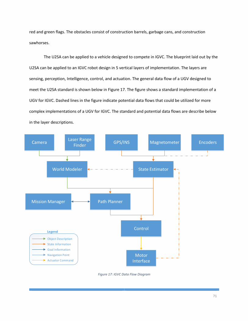
71
red and green flags. The obstacles consist of construction barrels, garbage cans, and construction
sawhorses.
The U2SA can be applied to a vehicle designed to compete in IGVC. The blueprint laid out by the
U2SA can be applied to an IGVC robot design in 5 vertical layers of implementation. The layers are
sensing, perception, Intelligence, control, and actuation. The general data flow of a UGV designed to
meet the U2SA standard is shown below in Figure 17. The figure shows a standard implementation of a
UGV for IGVC. Dashed lines in the figure indicate potential data flows that could be utilized for more
complex implementations of a UGV for IGVC. The standard and potential data flows are describe below
in the layer descriptions.
GPS/INS
State Estimator
Path PlannerMission Manager
Control
Motor Interface
Camera
World Modeler
Laser Range Finder
Magnetometer
Object Description
State Information
Goal Information
Navigation Point
Actuator Command
Legend
Encoders
Figure 17: IGVC Data Flow Diagram
72
4.1.1 U2SA Implementation
The U2SA implementation for a UGV can be broken down into 5 layers: sensing, perception,
intelligence, control, and actuation. The sensing layer includes all of the proprioceptive sensors and
exteroceptive sensors. The perception layer includes the State Estimator and any exteroceptive sensor
processing services that are developed beyond the core implementation. Intelligence includes the Path
Planner, the World Modeler, and the Mission Manager. The control layer includes the Control System
services. The actuation layer contains the motor interface service which may, depending on the type of
motors, collect encoder data and transmit the velocity information to the State Estimator.
4.1.1.1 Sensing
The GPS, IMU, and encoders are all types of state sensors. The service implementation for these
sensors would subclass the Proprioceptive Sensor class. The GPS would populate the location, altitude,
speed, and heading portions of the State Information message, as well as the standard deviations for
each field that is available and pass that information on to state estimator service. The IMU would
populate the speed and acceleration fields for the orientation part of the State Information message.
The encoders should populate the X and Y speed fields of the state information message and pass that
on to the State Estimator service.
Additional sensors, such as the LIDAR, RADAR, Cameras, Ultrasonic, or IR Range sensors would
be subclasses of the Exteroceptive Sensor service. Each of these services should also process the
incoming data from the sensors and extract object descriptions and pass the descriptions on to the
world modeler. There may be certain timing requirements for a systems response or scan rate that
might require that an additional processes service be created to collect the data from the Exteroceptive
Sensor service and process it on a separate thread.
73
The Camera service should identify the white lines painted on the ground and build an object
description. The white lines can be describe in several different ways. The lines could be broken up into
discrete points that capture the outline of the line or they can be described as a geometric line by
specifying two endpoints, or a multi-point line.
4.1.1.2 Perception
The State Estimation algorithm is fairly straight forward for a simple UGV. With a high enough
accuracy of GPS and magnetometer data, the State Estimator should subscribe to the data from the GPS
and the magnetometer and build a new State Information object that contains the position data from
the GPS and the heading data from the magnetometer and publish that new State Information to the
services that subscribe to it. Additional filtering could be done on heading using GPS heading, or on
location using inertial measurement from an IMU or encoders if necessary. However, the sensors on
board the ERAU ground vehicles are typically high enough accuracy that the filtering will make little
difference. A ten centimeter deviation in the GPS position on a one meter wide vehicle is not an extreme
error that always need to be accounted for if the obstacles are spaced widely apart. If additional filtering
is required, the information from the encoders, IMU, and the deviation could be supplied to a wide
variety of filters. Many different state filters could be implemented in the State Estimator like a Kalman
filter, an Alpha-Beta filter, a Bayesian Estimator, and many others.
The World Modeler can take many forms for a UGV. For the most part, Embry-Riddle ground
vehicles do not maintain a persistent map of the environment, but reacts only to the data that the
sensors can collect at any given instant. This can easily be implemented in a World Modeling service.
The World Modeler would have memory stores for objects from the camera and objects from the LIDAR.
Every time a new message comes in from the camera or the LIDAR, the World Modeler would simply
74
overwrite any previous data in the memory stores and pass on the new information to the Object
Description subscribers.
For a more complex World Modeler that maintains memory of the environment, the camera
and LIDAR services would have to identify the type of object and its location and assign a unique ID to
each object. When the World Modeler gets new information for either sensor, it will need to compare
that object to every other object in the data store to ensure that it is not entering duplicate object into
the world model. In this case, the World Modeler would most likely need to subscribe to the State
Information message so that it can assign a global position to the objects instead of just a local position.
The Object Description message has a reference frame field just for this purpose so that systems can
handle objects from different reference frames correctly.
4.1.1.3 Intelligence
The intelligence layer contains the Mission Manager and the Path Planner. The Mission Manager
is fairly simple for IGVC because the goals are a simple sequential list of waypoints, and the waypoints
do not update while the system is running. The waypoints will be specified with a threshold distance
that the system must be within to consider the goal completed.
The Path Planner for an IGVC UGV can take many different forms depending on the strategy of
the system developers. The Path Planner could be a simple reactive algorithm that collects the State
Information from the State Estimator and the Waypoint Goal from the Mission Manager and calculate
the distance and direction for the vehicle to get to the waypoint. Once the distance and direction are
calculated, the vector would be modified to account for the objects that the Mission Manager has
published that stand between the vehicle and the waypoint.
A more advanced UGV would utilize all map data stored in the World Modeler and create an
optimal path for the vehicle to travel. Interestingly, the same path planning algorithm could be used for
75
this complex path planner or the simple path planner that only uses visible objects. The difference for
this type of path planning would be in the World Modeler. A Path Planner could be written to plan a
path around all of the objects that it receives from the World Modeler, and thus, to add global path
planning considerations, only the World Modeler would have to be changed.
4.1.1.4 Control
The Control System is responsible for taking a drive point in space and calculating what the
wheel speeds need to be over the next time step to get the vehicle there. The most common control
algorithm in IGVC UGVs is a PID. The U2SA supports PID implementations as well as many other control
algorithms. For any control system, the service, upon receipt of a new drive point, would calculate the
wheel commands that are required to get the system to that point.
4.1.1.5 Actuation
Outputs for a UGV would be various types of Actuator subclasses. To control something like
wheel speed, an Actuator service subclass would be created for each wheel hardware interface. The
actuator command would be a percentage from -100%-100%. Where -100% is full reverse and 100% is
full forward, and 0 velocity at 0%. The Actuator service subclass would translate that command into the
proprietary format necessary to send to the motor controller.
The actuation layer depends heavily on how the software is connected to the hardware. Each
hardware interface should have its own service. So if each of the two wheels in a differential steered
vehicle has a serial port, then there should be two services: one for left wheel and one for right wheel.
However, if the two wheels in an IGVC UGV are connected on the same communication bus, only one
Actuator service is required. The Actuator service would open up the serial port or other communication
channel, set necessary baud and other parameters, and then when a new wheel command is received,
the service would send it over the hardware communication channel.
76
In the Embry-Riddle UGVs, smart motors are typically used which not only accept commands
over serial but also publish encoder readings over the same serial interface. Because only one service
can open the serial port, the actuator service would have to be written such that not only are commands
sent to the motors, but sensor data is collected from the motors. The Actuator service could then
register as a publisher of State Information and send the velocity data to the State Estimator. This shows
one of the benefits of the U2SA very well. If the developers originally write the Actuator service to only
send out commands, it is then quick and easy to modify the service to read the encoder data and publish
the data. Nothing in the State Estimator needs to be changed to accept the new information, it will just
receive the encoder data.
4.1.2 U2SA Advantages
There are a number of advantages of the U2SA over existing UGV architectures. Specifically,
compared to a platform like the ArduRover, the U2SA allows for a wider range of sensors and easier
substitution of sensors or algorithms. The U2SA also allows a system to operate asynchronously which is
an advantage over a device like the ArduRover. Additionally, the U2SA has an advantage over a JAUS
implementation in that U2SA service are more loosely coupled, allowing for more dynamic system
configurations.
The ArduRover is compiled specifically for an ArduPilot board with an ATmega2560
microprocessor. The problem with this design is that the ArduRover then depends on the hardware
implementation and is limited to the 8 PWM inputs, 8 PWM outputs, and 14 digital General Purpose
Input/Output (GPIO) [5]. The ArduRover is also limited to simple digital and analog inputs and digital
outputs. These problems do not exist in a U2SA implementation because the U2SA requires a computer
processor with an operating system. The peripherals that can be connected to an embedded computer
are the same as what can be connected to a desktop computer. Therefore, adding a new network or
77
USB peripheral to a U2SA system is as easy as writing a new service to parse the communication
protocol and publish the data on the MOM, whereas on the ArduRover, network and USB peripherals
are not an option. The U2SA can be implemented on most computer platforms and the choice of
platform is left to the developer depending on what types and how many peripherals the systems needs
to connect to.
The ArduRover code has highly coupled software modules within their systems. In ArduRover,
due to the constraints imposed by the microprocessor, the software is written as a monolithic
sequential program. Many variables are used globally and can be accessed and modified by any of the
pieces of software within the ArduRover platform. The U2SA handles this problem by breaking
functionality down into independent services that run concurrently. Such concurrency and independent
modules are not possible on an ArduPilot board with the ATmega processor. Due to the level of service
abstraction defined in the U2SA, it is not possible for a piece of software, like one of the sensor services,
to interfere or change the program variables of the Mission Manager. This is an advantage because
services are lowly coupled and are allowed to execute their piece of functionality independently without
interference from other pieces of software.
Consider the scenario where a UGV developer wants to add a new obstacle sensor to the
platform. In the case of the ArduRover, the new sensor is limited to an ultrasonic range finder without
writing new software and modifying existing software. Connecting the new sensor to the data flow in an
ArduRover is a grueling task that requires detailed knowledge of how the ArduRover works and how the
path planning algorithms work. In the U2SA, this is not the case. To add an ultrasonic range finder to a
U2SA system, a developer will create a new service to read in the data from the sensor, calculate if the
sensor sees an object, and determine how far away the object is from the sensor. The configuration of
the sensor service will contain the configuration of where on the vehicle the sensor is located and the
78
service can then put the distance measurement into an object description message in the local
reference frame. The service then publishes that message and no new development needs to be done. If
the World Modeler was designed to the U2SA specification, then it will be able to accept the new
stream of object descriptions and include those new objects in the outgoing messages to the Path
Planner. Because the ArduRover software is designed specifically for the hardware and sensors that are
sold with the ArduPilot, the path planning algorithm was designed for the specific inputs from those
sensors. To add a new object sensor, the ArduRover code must be reworked and possibly a whole new
algorithm implemented to allow for new sensor
In JAUS, a component in the system needs to know detailed information about the other
components that are expecting the data from the first component. A component, or service, that
publishes a message must know the network address, port, system ID, node ID, and component ID of
every other component that is requesting the published message. The MOM that is required by the
U2SA will direct and route message traffic as needed and service will not need to maintain information
in memory about the recipients of the messages.
4.2 RoboBoat Competition
The RoboBoat Competition in 2013 was a complex challenge consisting of many different tasks
and subtasks that needed to be completed. The first mandatory task was to navigate through two sets
of buoys as fast as possible. After the speed challenge, the boat must navigate through 10 to 15 sets of
orange and green buoys. The boat will know that it has reached the end of the buoy channel once it
reaches a large blue buoy. After exiting the buoy channel, the system has the option of choosing to do
any of the optional tasks. The more tasks completed, the higher the system will score in the
competition. One of the tasks is to identify colored rings suspended vertically on the shore. The system
has to shoot a Nerf dart through one of the rings with a specific color that is given to the team at the
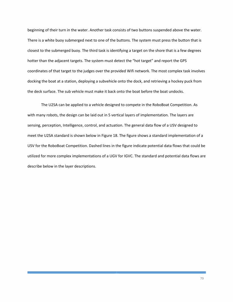
79
beginning of their turn in the water. Another task consists of two buttons suspended above the water.
There is a white buoy submerged next to one of the buttons. The system must press the button that is
closest to the submerged buoy. The third task is identifying a target on the shore that is a few degrees
hotter than the adjacent targets. The system must detect the “hot target” and report the GPS
coordinates of that target to the judges over the provided Wifi network. The most complex task involves
docking the boat at a station, deploying a subvehicle onto the dock, and retrieving a hockey puck from
the deck surface. The sub vehicle must make it back onto the boat before the boat undocks.
The U2SA can be applied to a vehicle designed to compete in the RoboBoat Competition. As
with many robots, the design can be laid out in 5 vertical layers of implementation. The layers are
sensing, perception, Intelligence, control, and actuation. The general data flow of a USV designed to
meet the U2SA standard is shown below in Figure 18. The figure shows a standard implementation of a
USV for the RoboBoat Competition. Dashed lines in the figure indicate potential data flows that could be
utilized for more complex implementations of a UGV for IGVC. The standard and potential data flows are
describe below in the layer descriptions.
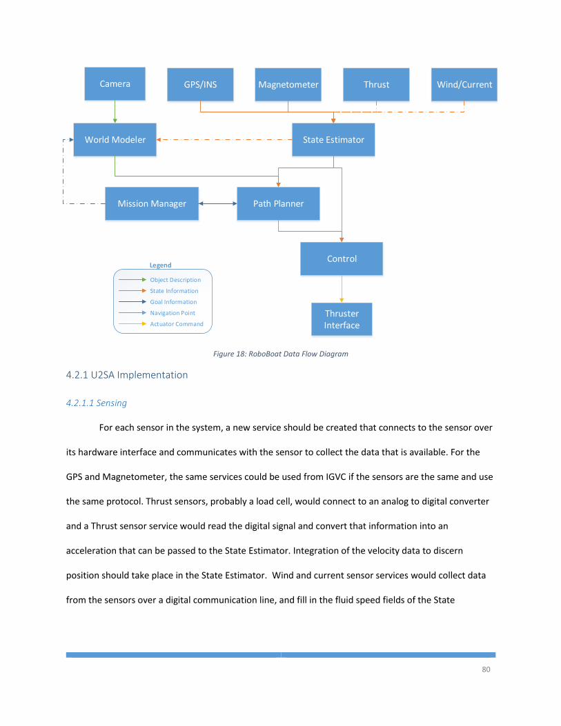
80
GPS/INS
State Estimator
Path PlannerMission Manager
Control
Thruster Interface
Camera
World Modeler
Magnetometer
Object Description
State Information
Goal Information
Navigation Point
Actuator Command
Legend
Thrust Wind/Current
Figure 18: RoboBoat Data Flow Diagram
4.2.1 U2SA Implementation
4.2.1.1 Sensing
For each sensor in the system, a new service should be created that connects to the sensor over
its hardware interface and communicates with the sensor to collect the data that is available. For the
GPS and Magnetometer, the same services could be used from IGVC if the sensors are the same and use
the same protocol. Thrust sensors, probably a load cell, would connect to an analog to digital converter
and a Thrust sensor service would read the digital signal and convert that information into an
acceleration that can be passed to the State Estimator. Integration of the velocity data to discern
position should take place in the State Estimator. Wind and current sensor services would collect data
from the sensors over a digital communication line, and fill in the fluid speed fields of the State
81
Information message. This data would be combined with other velocity data in the State Estimator to
determine the ground speed of the vehicle.
The GPS, IMU, thrust, wind and current sensors are all types of state sensors. The service
implementation for these sensors would subclass the Proprioceptive Sensor class. Most of the sensors
act the same way that they would for a ground vehicle. The differences are the wind and current
sensors. Those sensors would populate the fluid speed fields in the State Information message. The fluid
speed would have to be calculated based on the vehicle’s profile considering sail area above the water,
and the displacement in the water.
In maritime applications, it is often more important to recognize an object’s color. Thus, one of
the three defined types of Object Description must be extended to create a new object description
message. Since there are so many different colors of buoys in the RoboBoat Competition, it would make
sense to create a new Buoy class that extends shape description, specifies the shape of a sphere, and
adds a field for color. The color should be an enumeration field that allows for orange, green, yellow,
blue, and any other colors that could be buoys. A U2SA RoboBoat would also need to create object
description classes for the hula-hoops on the land, the hot targets on the land, the hockey puck, and the
red buttons on the surface of the water.
4.2.1.2 Perception
To achieve perception in a RoboBoat system, the Camera service, or an additional image
processing service, must process the images that come in from the camera and detect the different
types objects that object descriptions were created for. Each image must be process for the types of
objects that the system could expect to see and create an object description class that best represents
the object in the environment.
82
The system may only want to identify certain types of objects during certain phases of the
competition. Thus, the Camera service, or the camera processing service, may want to register to the
Mission Planner’s Goal Information messages so that the image processing can change states and only
look for certain types of objects. Alternatively, a different image processing service could be written for
each type of object that the system is looking for and all of these services could run in parallel on the
most recent image. This would be very processor intensive. So, again, it may be necessary to have the
image processing services subscribe to the goal information messages and only process an image if the
system is in the correct phase of the competition. All of these different solutions are readily supported
by the U2SA and developers have the freedom to create the system that they desire without any undue
complexities imposed by the system architecture.
4.2.1.3 Intelligence
The intelligence of the RoboBoat resembles a finite state machine. Each phase of the
competition is looking for different objects in the environment. A state diagram is shown below in Figure
19. The diagram shows the different states that the system must operate in and the transitions that
must be made from one state to another. The transition conditions are controlled by the Mission
Manager while the actual evaluation of the conditions and state transitions are handled by the Path
Planner.
The RoboBoat has many decisions to make in a single competition run. The transitions for the
speed gate and the buoy channel are known ahead of time. However, the transition to the different task
states are open ended and can be changed depending on a team’s strategy. A team may only want to do
2 of the 4 tasks and then return to the dock through the buoy channel. Thus, in the state diagram, there
is a diamond that represents the task decisions. After each task, the system should evaluate how close
the other tasks are, how long each task might take, probability of completion, and other factors to
83
determine which task should be done next or if the system should start the ending sequence by
returning to the dock. If there are multiple tasking options, like in RoboBoat, a U2SA Mission Manager
should publish all currently available Goal Information messages, and the decision of which task to
attempt next should be calculated in the Path Planner. This is because the Path Planner already has
information about the environment map and the state of the system. To calculate the best path
between goals in the Path Planner will reduce coupling of modules by ensuring that the Mission
Manager does not need access to new sets of data.
The transition conditions must be specified in the Goal Information objects. For each task, a
different Goal Information subclass must be made and specified in the Mission Managers mission
configuration file. Multiple conditions may need to be specified. An example Goal Information subclass
would be for the HulaHoop Goal class that require either 6 Nerf bullets are fired, or a timeout of 90
seconds at the station. The HulaHoop Goal class would need a field to store how many shots have been
fired and a field for the timestamp of when the system arrived at the station. This object would be
created by the Mission Manager as it reads the mission configuration file when the system is initialized.
When the Path Planner gets the Goal Information message that contains the HulaHoop Goal class, the
Path Planner will change states to the Hula-Hoop state. In the Hula-Hoop state, the Path Planner will
navigate to the Hula-Hoop station, usually through a GPS waypoint. Once the system has arrived at the
waypoint, the Path Planner will set the timestamp field in the HulaHoop Goal object. Also, any time that
the Path Planner sends a control command to fire the Nerf gun, it should increment the value in the
HulaHoop Goal object. Lastly, while in the Hula-Hoop state, the Path Planner needs to check the time
elapsed and the shot count and if either of those surpass the threshold constants specified in the
HulaHoop Goal class. If either threshold is surpassed, the Path Planner will set the completed field to
true and publish it back to the Mission Manager.
84
In addition to the normal USV outputs, a RoboBoat competitor would have to also control a sub-
vehicle that could be deployed onto the dock to retrieve the hockey puck. There are a number of ways
that this could be handled by a U2SA application. The sub-vehicle could transmit all of its sensor data
back to the main platform through the middleware, the main platform would process the information as
part of its own service implementations, and then the main platform would transmit actuator
commands back to the platform. This solution may not be reasonable for a time sensitive
implementation like Embry-Riddle’s entry which used a Quadrotor aerial vehicle as the sub-vehicle. In
this case, the quadrotor should have its own implementation of the U2AS services for sensing, planning,
and control. However, the mission manager would reside on the main boat platform and only when the
boat is ready to deploy the sub-vehicle would the mission manager publish the tasking information for
the quadrotor. At which point, the quadrotor would respond by commencing its procedures for
navigating to the dock and retrieving the hockey puck.
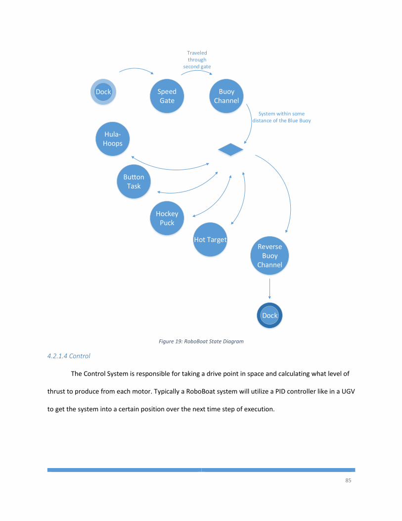
85
Dock Speed Gate
Buoy Channel
Hula-Hoops
ButtonTask
Hockey Puck
Hot TargetReverse
Buoy Channel
Dock
Traveled through
second gate
System within some distance of the Blue Buoy
Figure 19: RoboBoat State Diagram
4.2.1.4 Control
The Control System is responsible for taking a drive point in space and calculating what level of
thrust to produce from each motor. Typically a RoboBoat system will utilize a PID controller like in a UGV
to get the system into a certain position over the next time step of execution.

86
4.2.1.5 Actuation
Actuator services would mostly operate in the same manner described above in the IGVC
input/output section. The difference in the Control service and the Actuator services are that instead of
wheel speed, a surface vehicle would send thrust values to the Actuator which in turn would translate
that into the proprietary message necessary to communicate with the speed controllers.
4.2.2 U2SA Advantages
The advantages for the U2SA in a maritime environment are numerous when compared to
existing architectures. The ArudPilot system does not currently have a solution for maritime
applications. While the ArduPilot could navigate a boat through a series of waypoints, it does not
support the types of peripheral devices that are required for more complex maritime applications. This
is largely because a maritime application would require camera feeds or high fidelity LIDAR data to
detect obstacles in the water, which the ArduPilot hardware could not process. There is also no
mechanism in the ArduPilot to feed in a series of obstacles from an external source. In the U2SA, any
service can publish Object Description messages to the Path Planner, but in the ArduPilot there is no
public interface to the path planning algorithm to allow external Object Descriptions to be taken into
account.
4.3 RoboSub Competition
The RoboSub Competition is a fully autonomous underwater unmanned vehicle. The
competition is made slightly more difficult than IGVC and RoboBoat because there is no easy way to
determine a global position underwater through something like GPS. The tasks for RoboSub include
navigating through colored gates underwater, bumping specific color buoys underwater, following visual
cues to navigate in a specific direction, and more. There are also different colored hoops underwater
that the sub must shoot a torpedo through and different bins on the bottom of the pool that the sub
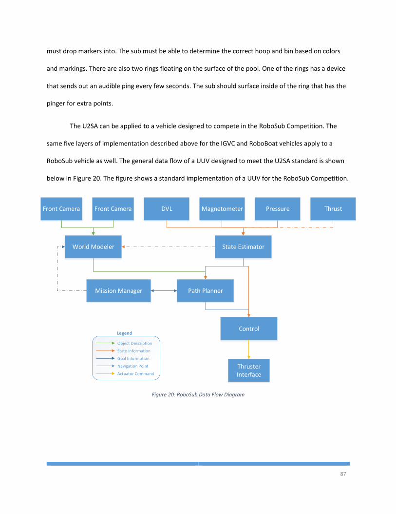
87
must drop markers into. The sub must be able to determine the correct hoop and bin based on colors
and markings. There are also two rings floating on the surface of the pool. One of the rings has a device
that sends out an audible ping every few seconds. The sub should surface inside of the ring that has the
pinger for extra points.
The U2SA can be applied to a vehicle designed to compete in the RoboSub Competition. The
same five layers of implementation described above for the IGVC and RoboBoat vehicles apply to a
RoboSub vehicle as well. The general data flow of a UUV designed to meet the U2SA standard is shown
below in Figure 20. The figure shows a standard implementation of a UUV for the RoboSub Competition.
DVL
State Estimator
Path PlannerMission Manager
Control
Thruster Interface
World Modeler
Magnetometer
Object Description
State Information
Goal Information
Navigation Point
Actuator Command
Legend
Pressure ThrustFront Camera Front Camera
Figure 20: RoboSub Data Flow Diagram
88
4.3.1 U2SA Implementation
4.3.1.1 Sensing
The IMU, DVL, magnetometer, thrust, wind and current sensors are all types of state sensors.
The service implementation for these sensors would subclass the Proprioceptive Sensor class. The DVL
would provide velocity in three dimensions that would be passed to the state estimator which could
integrate the velocity over time to collect position information. The IMU, magnetometer, thrust, wind
and current sensors would all operate similarly to the above descriptions for IGVC and RoboBoat.
4.3.1.2 Perception
The perception layer of a RoboSub system is very similar to that of a RoboBoat system. Most of
the tasks involve observing objects and interacting with the environment. Due to the fact that the
RoboSub does not have a simple or cheap solution to localization, like a GPS, most of the localization
and state determination depends on observing the environment. Therefore, the perception layer
focuses heavily on processing the camera feeds and only slightly on the state sensors.
For each task in the competition, the developers need to build object description classes that
represent all of the relevant information needed to describe the object in the environment. For objects
like the orange and green gates, the developers could use a standard Point Cloud object that contains a
UID that specifies the gate object and a single point in space that specifies the center of the gate. The
processing of the image data to identify the gates can be done in the camera service itself or in an
additional processing service. That is left up to the developer for implementation. Other objects can be
described similarly with just a single point. Object description messages should contain only enough
information for the Path Planner to act on. Extraneous data will only bog down the communication lines
between services and add additional processing to each service that utilizes the information. So if the
89
image processing service can boil down the object to single point, then it will be easier to develop an
effective World Modeler and Path Planner.
4.3.1.3 Intelligence
The intelligence layer for a RoboSub system includes the Mission Manager and the Path Planner
services. Once again, the Path Planner is a finite state machine that will change states when different
tasks have been completed. The competition usually flows from one task to the next and it is difficult
for a system to bypass any task because of the pathways laid out on the pool floor. There are two
instances of the sub having a choice of which task to do next. Those are when the sub can choose to
shoot the torpedo or drop the marker, and when the sub can choose to do the pinger task or the
manipulation task. The various task states and their transitions are shown below in Figure 21.
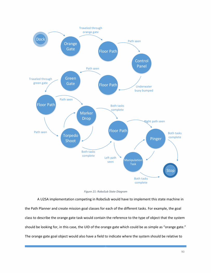
90
DockOrange
GateFloor Path
Traveled through orange gate
Path seen
Control Panel
Floor Path Underwater buoy bumped
Green Gate
Path seen
Floor Path
Traveled through green gate
Marker Drop
Torpedo Shoot
Floor Path
Manipulation Task
Pinger
Path seen
Path seen
Both tasks complete
Both tasks complete
Stop
Right path seen
Left path seen
Both tasks complete
Both tasks complete
Figure 21: RoboSub State Diagram
A U2SA implementation competing in RoboSub would have to implement this state machine in
the Path Planner and create mission goal classes for each of the different tasks. For example, the goal
class to describe the orange gate task would contain the reference to the type of object that the system
should be looking for, in this case, the UID of the orange gate which could be as simple as “orange gate.”
The orange gate goal object would also have a field to indicate where the system should be relative to
91
the object. In the case of the orange gate the destination should be a few feet beyond the center of the
gate. This way, when the image processor locates the center of the gate (relative to the center of the
vehicle), passes that to the World Modeler, which in turn passes the center of the gate to the Path
Planner, the Path Planner can calculate a path to get the vehicle from where it is relative to the gate, to
the desired position beyond the gate and transmit a drive point to the control system.
4.3.1.4 Control
The Control service for a RoboSub is very similar to that described above in the IGVC and
RoboBoat Control sections. Typical control systems for RoboSub entries are PID controllers that
calculate the thrust setting for the motors based on a filtered stream of heading and distance errors.
Any type of modern control system can be implemented in the U2SA provided that the control system
accepts the vehicles location error and puts out a control signal to send to the thrusters.
4.3.1.5 Actuation
Actuator services would mostly operate in the same manner described above in the RoboBoat
section. Additional outputs for the RoboSub might include mechanisms to launch the torpedoes or drop
the markers. These would be binary controls and operate as a 100% command means launch/drop, and
anything less than 100% means do not launch. The torpedo/marker Actuator sub-classes would translate
the -100%-100% command into whatever hardware command is necessary to perform the operation,
like generating a PWM pulse on a digital pin.
4.3.2 U2SA Advantages
The U2SA provides a few key advantages for underwater applications. These advantages include
the ability to operate without a state estimator, creating custom goals with custom completion criteria,
and the ability for the World Modeler to change which sets of objects are being broadcast based on the
mission goal.
92
The U2SA provides an easy solution for handling systems without a State Estimator. Systems like
ArduPilot utilize GPS waypoints as goals and therefore cannot operate without a State Estimator. In the
U2SA, it is possible to specify a mission goal based on proximity to an object in the local frame. In this
case a State Estimator is not required at all because path planning and navigation calculations occur
based on the objects in the world model.
In a system like the ArduPilot, creating mission goals is a complicated procedure involving a
multistep process that requires modification of multiple software files between the ardupilot source
code and ground station source code. In the U2SA, it is easy to create a new type of Mission Goal object,
specify the goal in the Mission Manager XML file, and write a new state in the Path Planner for handling
that type of object.
Another advantage of the U2SA is that the World Modeler or the Exteroceptive Sensor services
can subscribe to the mission goals from the Mission Manager and change behavior based on the current
task. The World Modeler may only want to publish object descriptions that are relevant to the current
task. Likewise, an image processing service may only want to execute a certain algorithm based on the
current task. An example would be when the RoboSub is performing the buoy task, the image processor
does not need to be searching for the orange gate. The U2SA allows this to occur so that processing load
and the amount of data transferred is limited to only necessary information.
4.4 Student Unmanned Aerial Systems Competition
The SUAS Competition is the only AUVSI competition where human operators are allowed in the
loop for the competition mission scenario. However, the more hands off the human operators are, the
higher the team scores. The SUAS competition requires a fixed wing or rotorcraft vehicle to take off
autonomously, fly through a series of GPS waypoints, and then search an area for targets laid out on the
ground. The targets are pieces of plywood that have been painted different colors and marked with
93
different alpha-numeric characters. The system, preferably autonomously, should report the target
locations, the target color, the target orientation, the alpha-numeric character, the alpha-numeric
character’s color, and the target orientation to the judges. The competition also requires that teams be
able to update their flight plan mid-mission and add additional search areas.
The SUAS competition provides an interesting challenge to the U2SA because the human
operators must be able to interact with the system while it is competing. This means that the system
must add an additional service on the Ground Control Station (GCS) computer. Having a network-ready
message oriented middleware is crucial here or the developers will have to define their own protocols
for communicating with services onboard the aircraft. The data flow for a typical Embry-Riddle SUAS
platform is shown below in Figure 22.
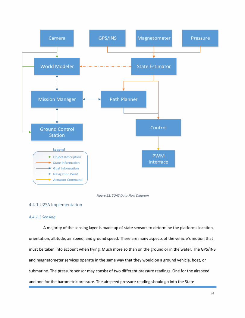
94
GPS/INS
State Estimator
Path PlannerMission Manager
Control
PWM Interface
World Modeler
Magnetometer
Object Description
State Information
Goal Information
Navigation Point
Actuator Command
Legend
PressureCamera
Ground Control Station
Figure 22: SUAS Data Flow Diagram
4.4.1 U2SA Implementation
4.4.1.1 Sensing
A majority of the sensing layer is made up of state sensors to determine the platforms location,
orientation, altitude, air speed, and ground speed. There are many aspects of the vehicle’s motion that
must be taken into account when flying. Much more so than on the ground or in the water. The GPS/INS
and magnetometer services operate in the same way that they would on a ground vehicle, boat, or
submarine. The pressure sensor may consist of two different pressure readings. One for the airspeed
and one for the barometric pressure. The airspeed pressure reading should go into the State
95
Information xDot, yDot, and zDot field. This will be important to the State Estimator in the perception
layer.
The SUAS platforms do have a camera as a sensor, but it does not general contribute to the path
planning or control. The system does not detect obstacles or goals using the camera. The camera is
strictly used for surveillance and intelligence gathering. The only time that the camera will affect a U2SA
system is by possibly adding a waypoint to the Mission Manager where it believes an object of interest is
and determines that a closer look is needed.
4.4.1.2 Perception
The pressure sensors operate very differently in an aircraft than they do on a ground vehicle or
boat. The system uses differential barometric pressure to determine altitude. This may mean that an
additional data line needs to be made from the GCS to the pressure sensor or the state estimator so that
the GCS can report the barometric pressure at ground level and the aircraft can accurately calculate it’s
altitude above ground. An aircraft will also use pitot static pressure to determine the airspeed of the
vehicle, which in turn will allow the system to calculate the wind speed and direction by comparing the
airspeed to the ground speed provided by the GPS. This information can be calculated in the State
Estimator and passed on to the Path Planner through the fluid speed fields.
4.4.1.3 Intelligence
The Path Planning and Mission Manager algorithms for the intelligence layer is usually fairly
straight forward for an SUAS platform. The mission goals consist simply of GPS waypoints and there are
no obstacles to avoid in the air, at least not yet in the SUAS Competition. Special types of mission goals
could be defined for takeoff and landing procedures, however in many Embry-Riddle SUAS systems in
the past, the takeoff and landing were just additional waypoints in the flight plan at varying altitudes.
96
To improve on previous systems, creating a new type of mission goal for search areas would be
highly useful for various UAV missions. The search area mission goal will specify the outline of an area
that the system needs to search for targets. The Path Planner will then communicate with the World
Modeler to determine what areas have been seen, and at what resolution have they been seen. This
would require a new type of Object Description message to be transmitted from the World Modeler that
contains the pertinent information about the image. The Path Planner can then calculate a path around
the search area to ensure the highest quality coverage of the area without the user having to specify
hundreds of waypoint goals in the mission configuration to cover the search area.
In a more complex scenario, where sense and avoid is required, the Exteroceptive Sensor
services would report locations of other aircraft to the World Modeler and keep those locations updated
as new location reports come in from the ADS-B and RADAR systems. The Path Planner would receive
the aircraft locations as a Moving Sphere Object Description message. The sphere will specify the buffer
area that the aircraft needs to maintain between itself and the other aircraft in the air. The Object
description will also have to contain the information about the trajectory of the other aircraft. The Path
Planner then has to calculate a path to the goal while avoiding an interception with the other aircrafts
buffer envelope.
4.4.1.4 Control
The control for an aircraft tends to be more complex than that for a ground vehicle. Instead of
calculating PID control loops on two wheels or two thrusters, an aircraft has to take into account the
point that it wants to travel to, the altitude, the airspeed, and the ground speed. On the Paparazzi and
ArduPilot autopilots, the control is handled through cascading PID control loops. While the control
system may be more complex than the other domains, the U2SA is still capable of supporting the control
97
system. The only input to the control is a drive point in front of the vehicle and the only output is the
motor speed and the control surface positions.
4.4.1.5 Actuation
The actuation layer for an SUAS platform is also fairly straight forward like the intelligence layer.
On many aircraft the output signals to servos and to typical electronic speed controllers are a standard
PWM servo pulse. This signal is easy to generate with any microcontroller hardware or even many
embedded computer processors.
4.4.2 U2SA Advantages
The U2SA provides advantages for many types of UAVs and aerial missions. The advantages
include sense and avoid capability, reusable algorithms between fixed wing and rotorcraft, and
autonomous search and find capabilities.
The ArduPilot is a very successful hobby platform that can successfully operate a number of
different aircraft from fixed wing to rotorcraft. However, one of the drawbacks for the ArduPilot is that
it currently does not have a method, or hooks for future development of a sense and avoid algorithm.
The ArduPilot source code would need a major overhaul in order to accommodate an avoidance
algorithm and the hardware would need modifications to accept sensor data from a RADAR or ADS-B.
The U2SA already has the hooks for the World Modeler to maintain information about other aircraft in
the environment, and a well written generic avoidance algorithm from another domain could be reused
for planning a path to avoid the other aircraft.
One of the challenges of aerial vehicles is that fixed wing tend to have different
implementations than rotorcraft, like in the ArduPilot. In the U2SA, all of the core services can stay the
same between rotorcraft and fixed wing vehicles. The only software that needs to change between
different types of aircraft is the kinematics and dynamics of the vehicle in the control system. In some
98
types of control algorithms, the dynamic and kinematic equations can be abstracted to outside of the
actual Control service.
Another advantage of the U2SA over other implementations is that for searching algorithms, the
World Modeler can maintain a map of the ground area that has been seen and at what ground
resolution was achieved. If a certain area has not been covered to the highest resolution possible, it may
be advantageous to autonomously add additional waypoints so that high resolution images can be
collected for that area. Through this algorithm, the system could ensure that the entire search area is
seen at some minimum resolution, a feature that does not exist in other implementations like ArduPilot,
Paparazzi, or Piccolo autopilots.
4.5 U2SA FlightGear Implementation
In the early stages of the U2SA development, the architecture was called ERASMUS. The
ERASMUS architecture was defined and presented at the 2013 AUVSI Unmanned Systems North
America Conference [6]. During the development of ERASMUS and after the paper was presented, the
architecture was implemented as an Oracle Java application to run on an embedded Linux processor,
the ODroid-X. The ERASMUS implementation running on the ODroid communicated with the FlightGear
flight simulator and read and wrote data from the simulator’s network interface. The services in the
system, conforming to the U2SA, then processed the data and passed the information on to the next
service in the chain. The data propagated down the chain until it reached the Control service which then
published the flight commands for aileron, elevator, rudder, and throttle back to the simulator service
for transmission back to FlightGear. With FlightGear running on one computer in the network,
simulating a Cessna 172, and the U2SA implementation running on the ODroid, the U2SA successfully
piloted the Cessna through a series of 10 waypoints, including autonomous takeoff.
99
One of the key aspects of the U2SA and ERASMUS was to create a universal architecture that
can run on any operating system from Linux, Windows, Mac, or Android. This is why Java was chosen for
the FlightGear Implementation. The FlightGear implementation was written in Oracle Java with only
basic classes that are included in Java. In Android, the Dalvik compiler can handle most, if not all, of
Oracle’s Java code. Thus, the FlightGear implementation should be able to run on all of the different
platforms that it was designed for.
4.5.1 Interfaces
The service contract for this implementation included a communication protocol for inter-
service communication and a configuration interface. The logger interface was not added until a later
implementation of the U2SA.
4.5.1.1 Communicator
The communication interface was created in house instead of using a third party middleware.
The communication structure of the system required a central message broker called the
Communication Manager which was a separate service in the system which contained routing tables for
the different types of messages that could be transmitted between services. When a service wanted to
receive State Information messages, they sent a subscribe message to the Communication Manager and
the Communication Manager sent a message to all publishers of that message. When new publishers of
the message are created, they inform the Communication Manager and the Communication Manager
responds with the list of all current subscribers in the system. Although all of the services in this
implementation were meant to be on the same processor, the Communication Manager was designed
to route communication over the network through UDP. Any services that were running on another
machine only needed to know the IP address of the Communication Manager, and they could subscribe
and publish the same way as if they were on the same machine as the other services.
100
4.5.1.2 Configuration
The Configurator interface was implemented for this version of the U2SA as well. The
Configurator was a HashTable that looked up values based on a string name for the variable. The
configuration file was an XML file that specified a configuration variable as a “variable” tag that
contained attributes for the name, type, and value of the variable. The type was necessary so that the
Configurator could correctly parse the information contained in the value field. An example variable is
the Communication Manager IP address. It had to be a String and therefore could not be parsed the
same way that a number is parsed. The entry in the configuration file is shown here:
<variable name="COMMUNICATION MANAGER IP" type="string" value="localhost"/>
4.5.2 Services
Each implementation of the U2SA will have different services. The services that are necessary to
interface with the FlightGear simulator and control a Cessna 172 are the following: Simulator, State
Estimator, Mission Manager, Path Planner, and Control services. The data flow of the services is shown
below in Figure 23.
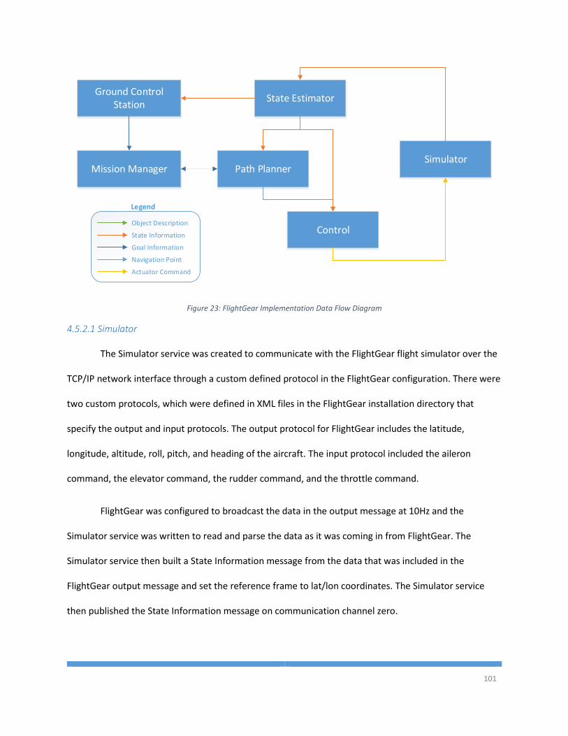
101
State Estimator
Path PlannerMission Manager
ControlObject Description
State Information
Goal Information
Navigation Point
Actuator Command
Legend
Simulator
Ground Control Station
Figure 23: FlightGear Implementation Data Flow Diagram
4.5.2.1 Simulator
The Simulator service was created to communicate with the FlightGear flight simulator over the
TCP/IP network interface through a custom defined protocol in the FlightGear configuration. There were
two custom protocols, which were defined in XML files in the FlightGear installation directory that
specify the output and input protocols. The output protocol for FlightGear includes the latitude,
longitude, altitude, roll, pitch, and heading of the aircraft. The input protocol included the aileron
command, the elevator command, the rudder command, and the throttle command.
FlightGear was configured to broadcast the data in the output message at 10Hz and the
Simulator service was written to read and parse the data as it was coming in from FlightGear. The
Simulator service then built a State Information message from the data that was included in the
FlightGear output message and set the reference frame to lat/lon coordinates. The Simulator service
then published the State Information message on communication channel zero.
102
When the Control service publishes commands for the control surfaces and the throttle, the
Simulator service will take those commands, between -100%-100%, and convert them into the input
message format that FlightGear requires for the command of the controls. The Simulator service will
then send the messages over the TCP/IP connection to FlightGear.
4.5.2.2 State Estimator
The State Estimator service for the FlightGear implementation is fairly simple. There is only one
source of proprioceptive sensor information, the FlightGear simulator. The accuracy of data received by
the simulator also doesn’t have any deviation or inaccuracy. Therefore, the State Estimator was written
as a pass-through service for the information received by the Simulator service. When a new message
from the Simulator comes in to the State Estimator, the State Estimator checks the presence vector of
the inbound message. Any fields that are populated in the inbound message are copied over to an new
outgoing message. After each field is checked and copied, the State Estimator publishes the new
message.
4.5.2.3 Mission Manager
The Mission Manager operates in the FlightGear implementation as described above in the
architecture description. The Mission Manager first reads in a list of goals, in this case Waypoints, from
an XML file. This implementation only supported 3 dimensional waypoints with latitude, longitude, and
altitude. So the waypoints in the file looked like the following:
<waypoint>
<y>37.466189</y>
<x>-121.134548</x>
<z>3000</z>
</waypoint>
103
From these XML descriptions of waypoints, the Mission Manager was able to create a list of
waypoints in memory that represented the 3 dimensional points in space that the system should fly to.
The order in which the Mission Manager executed the waypoints was determined by the order in which
the waypoints were entered into the XML file. In this implementation there was no way to change which
waypoint was currently being tracked. The system would forever loop through the series of waypoints
until either the services stopped or FlightGear stopped.
4.5.2.4 Path Planner
The Path Planner for the FlightGear implementation took the current waypoint in as a goal, and
the current state of the system. It then calculated the difference between the two points in the x, y, and
z dimensions. It then projected that difference vector onto the two dimensional x-y plane and shortened
it to a unit vector. The z differential was bounded between 1000 feet and 10 feet and scaled so that
±1000 feet or greater was full climb and ±10 feet or less was hold altitude. Everything between 1000 and
10 feet was scaled to the range 0 to 1.
4.5.2.5 Control
The Control service took in unit vectors from the Path Planner and converted those vectors into
aileron, elevator, rudder, and throttle commands. The control algorithms were proportional controllers
for altitude and for heading. The altitude differential from the Path Planner was mapped directly onto
the elevator command. The desired direction, calculated through the x-y unit vector, was scaled from -
180 through 180 to a range of 0 through one and mapped directly onto the aileron command. The
control algorithms successfully commanded the control surfaces to achieve the desired attitude as long
as the system didn’t go over about 40 degrees of bank.
104
4.5.3 Lessons Learned
In this implementation there was one configuration file for every service running on that
machine. This made the configuration file quite long and difficult to read. It was determined through this
testing that a more highly cohesive configurator was needed. In the most recent version of the U2SA
presented in this thesis, the configurator was defined as being specific to each service. In future
implementations of the U2SA, all services will have their own configuration files with only the variables
that are relevant to that service, but all of the services will have the same standard for specifying the
configurations.
The implementation was not a demonstration of advanced control algorithms, but rather that
the U2SA was a capable architecture and could be applied to aerial vehicles. For the purposes of the
demonstration, the Control service with proportional controls were capable of keeping the aircraft in
the air and maneuvering through waypoints. However, for a real application where the aircraft needs to
hit waypoints with high accuracy, the control algorithms need to be heavily modified.
4.6 U2SA Ground Vehicle Implementation
Shortly after the FlightGear implementation was created, a new implementation was designed
to handle a vehicle in the real world, rather than just a simulator. It was necessary to show that the
U2SA was not only capable of handling vehicle from multiple domains, but also that a large number of
the software services could be reused from one implementation to the next. Therefore, a UGV was
created to run a new implementation of the U2SA.
For this implementation it was desired to show that the architecture was capable of operating
not just on the Linux ODroid, but also on an Android device. The software for the FlightGear
implementation was written specifically to be used on any device that runs Java. The only new piece
that needed to be written for an Android device is an application wrapper.
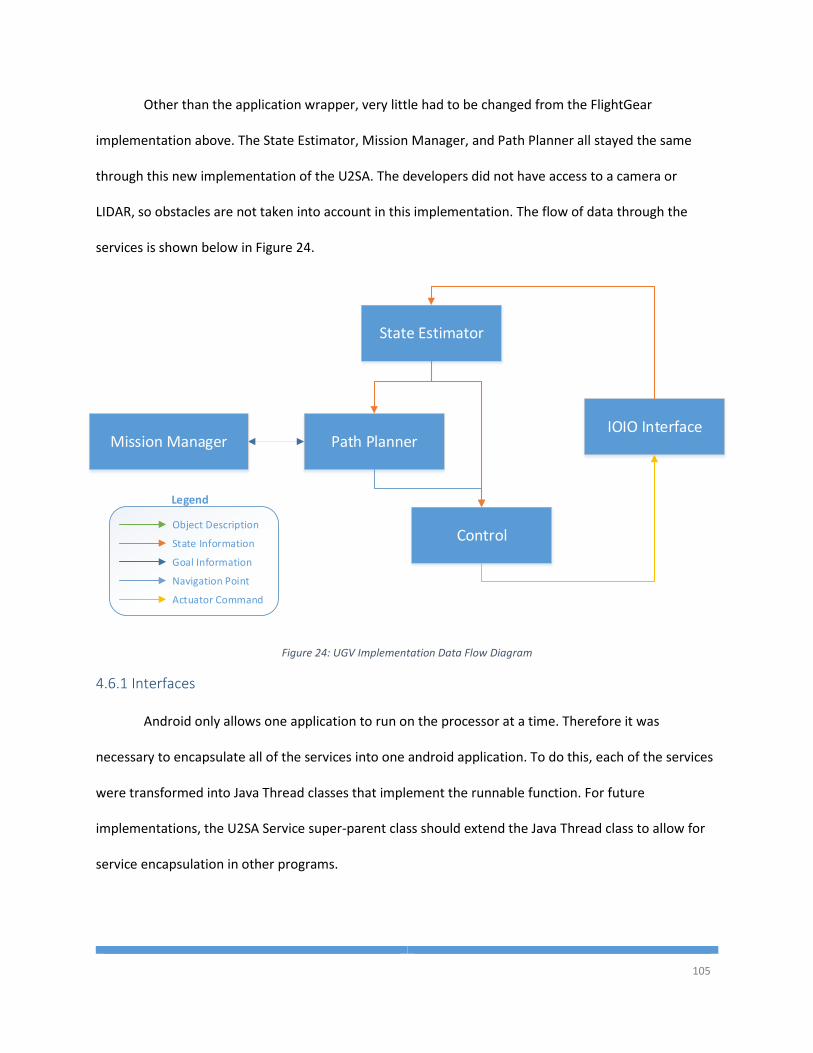
105
Other than the application wrapper, very little had to be changed from the FlightGear
implementation above. The State Estimator, Mission Manager, and Path Planner all stayed the same
through this new implementation of the U2SA. The developers did not have access to a camera or
LIDAR, so obstacles are not taken into account in this implementation. The flow of data through the
services is shown below in Figure 24.
State Estimator
Path PlannerMission Manager
ControlObject Description
State Information
Goal Information
Navigation Point
Actuator Command
Legend
IOIO Interface
Figure 24: UGV Implementation Data Flow Diagram
4.6.1 Interfaces
Android only allows one application to run on the processor at a time. Therefore it was
necessary to encapsulate all of the services into one android application. To do this, each of the services
were transformed into Java Thread classes that implement the runnable function. For future
implementations, the U2SA Service super-parent class should extend the Java Thread class to allow for
service encapsulation in other programs.
106
4.6.1.1 Communicator
The communication interface that was designed for the FlightGear implementation is easily
reused for the UGV implementation. This shows one of the largest benefits of the U2SA architecture.
The higher level modules are easily reused from application to application without need for
reconfiguration or recoding. The communicator interface is a plug and play solution that can easily be
applied to any system within an organization.
4.6.1.2 Configurator
The configurator can also be reused from the FlightGear implementation. Although in future
versions of the U2SA, the configurator must be extended so that each service has its own configuration
file as described above.
4.6.1.3 Logger
The UGV implementation of the U2SA is the first instance of the logging interface. The logger is
set up so that each U2SA service has its own log file. Logs from all of the services are stored in the same
directory and logs all have the same file format. The Logger is created in the constructor of the U2SA
Service class, so each service that subclasses U2SA Service will have the ability to call the log function
anywhere in the code without the added complexity of creating the file, putting data into the right
format, or knowing where the file location is. All of that is handled by the Logger interface which makes
the developer’s job significantly easier.
4.6.2 Services
The services for the UGV implementation of the U2SA is very similar to that of the FlightGear
implementation described above. The Control service had to be changed because there were fewer
control loops to control a ground vehicle than an air vehicle. The Simulator service also had to be
replaced with a new hardware interface service.
107
4.6.2.1 IOIO Interface
The Simulator service from the FlightGear interface was responsible for collecting sensor data
and writing actuator commands. However, none of that interaction was with a real system. For the UGV
run by an Android smartphone, a real hardware interface was needed. To connect to hardware, a IOIO
Bluetooth GPIO board was purchased and connected to the smartphone. The IOIO Interface service is
responsible for connecting to the IOIO board over Bluetooth, reading the sensor data over the serial
ports, and transmitting data to the digital GPIO pins to generate motor commands.
The Sensors for UGV are a GPS and a Magnetometer that each communicate over a TTL Serial
data line. If the computer actually had multiple serial interfaces, each of these sensors would have their
own service. However, since the IOIO has multiple serial ports, but only connects to the phone over one
Bluetooth channel, the sensor data is streamed into the U2SA implementation through a single IOIO
Interface service. After collecting the information from the IOIO, the IOIO Interface service broadcasts
the State Information message for the State Estimator to receive.
Additionally, the control outputs need to go to a motor controller through a PWM signal. Again,
the IOIO can be used to generate the two PWM signals for the motor controller. Thus, the IOIO interface
class must also have an outbound connection to the IOIO to send PWM duty cycles to the motor
controller.
4.6.2.2 State Estimator
The State Estimator from the FlightGear implementation above was designed for reuse in
systems that don’t need to do any filtering on the sensor data coming in. In this implementation, the
State Estimator takes every incoming State Information message and checks the presence vector for the
fields that are populated. The populated fields are copied into a new outgoing message and published
on the communication channel.
108
4.6.2.3 Path Planner
The Path Planner service is surprisingly the same exact service implementation as in the above
FlightGear implementation. The unit vector that describes the direction towards the waypoint is more
than sufficient for the Control service to create appropriate motor commands to navigate through
waypoints. The waypoints specified in the Mission Manager either omit the altitude field, or set it as
zero. In either case, the Path Planner calculates an altitude differential of zero and sends that onto the
Control service.
4.6.2.4 Mission Manager
The Mission Manager is also the same as in the FlightGear implementation because the goals for
an aircraft are the same as the goals for a ground vehicle, just simple waypoints. However, the UGV can
only navigate through 2 dimensional waypoints whereas the aircraft navigates through 3 dimensional
waypoints. Having designed the Mission Manager for parsing 3 dimensional location, 3 dimensional
orientation, and time on target attributes, the Mission Manager as implemented can handle waypoints
for any type of navigation goal in the global or local reference frame.
4.6.2.5 Control
Aside from the hardware interface, the Control algorithm is the only thing that really changed
from the above implementation. The control loops for a ground vehicle are clearly different from the
control loops for an aircraft, so this service was rewritten completely for this implementation.
The Control service for the UGV implementation takes the unit vector drive point calculated by
the Path Planner, and calculates wheel commands that will get the vehicle from the current position to
the unit vector position. A proportional controller for each wheel was enough to effectively maneuver
the system through waypoints during the testing of the U2SA implementation.
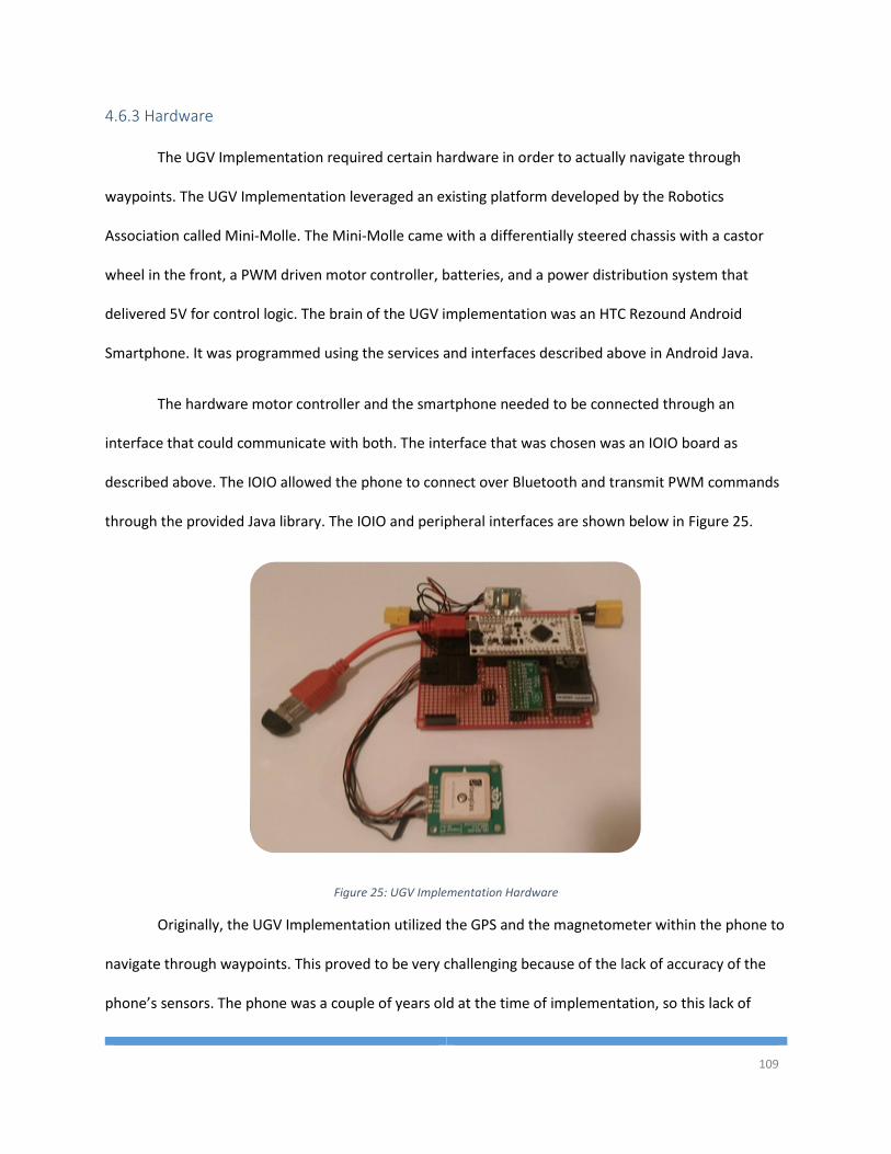
109
4.6.3 Hardware
The UGV Implementation required certain hardware in order to actually navigate through
waypoints. The UGV Implementation leveraged an existing platform developed by the Robotics
Association called Mini-Molle. The Mini-Molle came with a differentially steered chassis with a castor
wheel in the front, a PWM driven motor controller, batteries, and a power distribution system that
delivered 5V for control logic. The brain of the UGV implementation was an HTC Rezound Android
Smartphone. It was programmed using the services and interfaces described above in Android Java.
The hardware motor controller and the smartphone needed to be connected through an
interface that could communicate with both. The interface that was chosen was an IOIO board as
described above. The IOIO allowed the phone to connect over Bluetooth and transmit PWM commands
through the provided Java library. The IOIO and peripheral interfaces are shown below in Figure 25.
Figure 25: UGV Implementation Hardware
Originally, the UGV Implementation utilized the GPS and the magnetometer within the phone to
navigate through waypoints. This proved to be very challenging because of the lack of accuracy of the
phone’s sensors. The phone was a couple of years old at the time of implementation, so this lack of
110
accuracy should not eliminate smartphones from future development options. However, for this
application additional sensors were required and an external GPS sensor and an external magnetometer
were attached to the IOIO on two of the available serial ports. The GPS was a 3D Robotics GPS with a
uBlox LEA6 signal processor. The magnetometer was a Sparton Electronics SP3004D smart compass.
These sensors provided much higher accuracy and allowed the system to smoothly navigate through
waypoints.
In addition to the IOIO and the additional sensors, the UGV implementation hardware also
included an RC receiver and transmitter so that the user could safely drive the robot around and switch
between autonomous and manual control. To switch between autonomous and manual control the
auxiliary switch on the controller was mapped to a PWM pin on the RC receiver and that pin was
connected to a hardware PWM multiplexor (MUX). The default side of the MUX was for the manual
control and, when the auxiliary switch was flipped, the MUX would switch to pass through the PWM
commands from the IOIO.
All of the hardware in addition to the software developed under the U2SA successfully operated
the Mini-Molle and continuously navigated it through a series of waypoints through multiple tests.
111
Chapter 5 U2SA Analysis
The system architecture presented above in Chapter 3 was designed to meet the developer and
user requirements to make unmanned systems development quicker and more straightforward
approach to the systems engineering process. To ensure that this architecture provides the functionality
that is required by the developers, this chapter will analyze the user story requirements, the domain
specific requirements, as well as an analysis of SOA best practices.
5.1 Requirements Traceability
The U2SA was designed specifically to meet the requirements presented above in Chapter 2.
Those requirements are the basic purpose of the U2SA; to provide a simple, easy to use and easy to
implement system architecture that will propel unmanned systems development by making it faster to
create and implement and unmanned system design.
The first user story requires the system to not only be programming language independent, but
it requires that the software modules, or services, could be written in many different programming
languages. The U2SA meets this user story by providing the logical structure of the data communicated
between services in the system without specifying how that data is communicated. The development
team can determine what medium to transmit the data to other software modules based on what
interfaces are supported by the selected programming language. The U2SA would allow for each service
to be written in a different language if so desired by the development team.
The second user story requires that the system provide a well-defined communication protocol
for the data that is transmitted between the software modules. The U2SA provides data models for each
112
of the communication channels in the system. The data was abstracted from any single implementation
and accounts for many of the factors that are required in all of the unmanned system domains. It is
important to note that the U2SA does not provide a byte-for-byte protocol definition, merely the data
that needs to be communicated in order to successfully operate an unmanned system. This leaves the
development open to whatever protocol best fits the system application. If the system has limited
bandwidth, the developers can implement a bit stuffed protocol. Alternatively, if the system is not
limited for bandwidth, the developers can utilize built in Object serialization to transmit an entire object
without any need to develop a binary protocol for communication. In either case, the information that is
transmitted are the same in the U2SA.
The third user story deals with processor dependence of an implemented system. In order to be
truly universal, an unmanned system’s control logic needs to be able to execute on any type of
hardware. It is impossible to produce truly processor independent software, however, processor
independence can be maximized by serving the most common types of processors for the application. In
the case of an unmanned system, common processors include full PC multithreaded processors,
embedded ARM processors, and microcontrollers. The U2SA can run on any processor that is executing
an operating system like Window, Linux, or Mac. The U2SA could also run on a network of
microcontrollers. This provides an advantage to the U2SA over similar applications like the ArduPilot
that are designed for a specific set of hardware and processor.
Software coupling is a critical aspect of the software design process and is the crux of the fourth
user story. In other similar application described above in the literature review, many of the
architectures had high software coupling by enforcing multiple communication interfaces from a single
software module. The number of inputs and outputs of a software module should be as close to 1 as
possible to maintain low coupling. The U2SA provides service definitions that have few inputs and
113
outputs. The most highly coupled service in the U2SA is the Path Planner that relies on the current state,
the world model, and the current mission goals and outputs the stream of drive points. The coupling of
the Path Planner is significantly reduced however by providing the filtering of sensor data through the
State Estimator and the World Modeler. All of the other service communicate using only one or two
types of messages, thus providing low coupling throughout the system.
As future unmanned systems become more complex, it may be necessary, as it already is in
some instances, to distribute the system’s control logic among many processors in a network.
Applications like the ArduPilot are not capable of supporting distributed systems because the monolithic
software architecture is inflexible. JAUS and the U2SA are capable of supporting distributed systems.
The difference between the two is that JAUS requires configuration of the system because each
software module needs to know the address for each of the modules that are requesting data. The U2SA
calls out for a message oriented middleware that works on a topic type so that the software modules do
not require configuration to communicate their data to the other services in the system.
One of the pitfalls of the other architectures discussed in Chapter 1 is that none of them provide
a logical architecture view that shows the common pieces of a software module. It is widely accepted
that a development team should reduce the amount of software that is duplicated throughout the
system and that is what the sixth user story requires of the U2SA. The services were analyzed for pieces
of functionality that each service needed access to like configuration, logging, and the communication
interfaces. These common pieces were abstracted to the U2SA Service class that each service must
extend in the U2SA. This abstraction provides the service contract that is discussed below. It ensures
that each service in the system does these operations in the exact same way and reduces the amount of
software duplication in the development.
114
The seventh user story goes along the same lines as the fourth user story. Coupling should be
kept low throughout the system to ensure ease of implementation and maintenance. The fourth user
story, discussed above, involves the coupling of the individual classes within the software components,
whereas this user story concerns the level of detail that each service must know about the other
services in the system. As discussed throughout this thesis, the U2SA requires a MOM that is capable of
operating on topic types rather than specifically addressing the other modules in the system. The U2SA’s
MOM requirement helps users to abstract the services from each other and ensures that no service
needs to know any specific information about the other services in the system. Meeting this user story
gives the U2SA a big advantage over similar architectures in terms of system complexity and time spent
on configuration.
The eighth user story requires that a user be able to pick and replace an algorithm without
modifying any of the other services in the system. This requirement depends on the system meeting the
second and seventh user stories above. By defining the data transmitted between services and the
abstract nature of the MOM, a path planning algorithm or world modeling algorithm can be written in a
new service implementation without affecting the old implementation. Thus, by simply stopping the old
service and starting the new service, the system can completely replace an algorithm without ever
interfering with the operation of the system.
One of the biggest drains on design and development of an unmanned system is considering all
of the possible inputs and outputs that are currently needed, or will be needed in the future. Through a
U2SA compliant system, this drain on the development life cycle is eliminated. With a publish/subscribe
framework for message flow, a software module does not need to be aware of the other software
modules in the system and can just wait for new messages to appear. However, to handle new sources
115
or destinations of messages, a developer must carefully create the state estimator, mapping, and
control algorithms.
The State Estimator must be designed such that each sensor that publishes State Information
data has some unique ID so that the State Estimator knows where the data is coming from. When a
message comes into the State Estimator from a source that has never published before, the State
Estimator will have to register that sensor and, depending on the state estimation algorithm, it may
have to keep track of data over time from that specific sensor. A state estimation algorithm can use the
data and deviation fields in the State Information message to filter all of the incoming data and combine
the data into a best estimate. A State Estimator algorithm must be carefully designed to
programmatically scale to handle a varying number of sensor input streams.
Any type of mapping algorithm should be able to handle different types of exteroceptive data
streams. The object description message is a common interface that all sensors will create and transmit.
It is the responsibility of the sensor, or some intermediate service, to decipher the incoming sensor
streams and turn them into object description message. The object description messages will be
interpreted by the mapping algorithm and inserted into a map model according to the mapping
algorithm design. A mapping algorithm may need to keep track of objects over time if the objects are
moving, or are necessary goals to reach. There are two ways that a mapping algorithm could keep track
of objects over time. If the sensors are capable of keeping track of objects from one environment scan
to the next, then the sensor can populate the UID field in the object description message and the
mapping algorithm can associate the new data points to the already existing data points collected for
that UID. Also, the mapping algorithm could keep track of objects over time by using the source of the
object description to associate new messages with old messages from the same sensor and calculate
116
how much it has moved. This can also be used to supply environment information to a Simultaneous
Localization and Mapping (SLAM) algorithm.
Control algorithms are more difficult to make universal than the state estimator and the
mapping algorithms. It is necessary for a control algorithm to know about the actuators that exist in the
system and how they influence the system’s movement through the environment. However, it may be
possible with the U2SA that the developer does not need to modify the control algorithm code when a
new actuator is added. When the actuator services are turned on, they could publish a message that the
control system is listening to. This messages would contain the actuators name and how that actuator
affects the state of the system. It may be necessary to include which subsystem, like system state or
manipulator state, the actuator affects in the message if there are numerous subsystems that need to
be controlled. The control algorithm can then utilize the information about how each actuator affects
the state of the system and create a model of the vehicle and create commands to get the system into
the desired state.
5.2 Principles of a SOA
The principles of a Service Oriented Architecture are described above in Chapter 2. These
principles, proposed by Thomas Erl [11], are the 8 foundational constraints on a SOA design. Each of the
principles should be addressed as part of the SOA design process. The U2SA was designed with each of
the principles in mind and this section will expand on how the U2SA has met the standard for SOAs.
5.2.1 Standardized Service Contracts
As described above in Chapter 2, the standard service contract is an important requirement for
any SOA. Ensuring that each service operates the same way and makes the functionality known is critical
to any system operating with a SOA. This criticality is not different in the U2SA.
117
The U2SA supplies a well-defined service contract that ensures that each service implements the
same type of configuration, logging, communication, and identification. This architecture creates the
service contract through the super parent of all service classes in the system, the U2SAService class. The
U2SA service class implements each of the interfaces that are necessary to ensure that the system is
easily created and maintained over many years of service in an unmanned system. The U2SAService
class provides the contract that ensures that new services can be added to the system easily and allow
the new services to discover other services and communicate with other services without any need for
extra configuration on the developer’s part.
5.2.2 Service Loose Coupling
Low coupling is a difficult goal to reach in development of an unmanned system. Each service is
highly dependent on the other services higher in the data flow producing their data. If the State
Estimator isn’t running then the state information will never be updated and new commands will never
be propagated to the actuators. However, the dependency can be reduced to the point where a service
does not directly depend on another service, but only that the data exists in the communication
channels. This is what the U2SA does to provide loose service coupling. A service in a U2SA system is
dependent on an event to perform its tasks. The event is triggered by the receipt of a new message. The
loose coupling comes into play here because, in most cases, the service does not care where the data
came from.
5.2.3 Service Abstraction
Abstraction comes down to the idea that information that is not required, is hidden from the
users. In the case of a service, the information and implementation inside of a service can, and should,
remain hidden from the outside services until a message is created that contains the necessary
information. The U2SA has a high level of service abstraction due to the fact that the information
118
flowing in and out of services is defined in the data models. The information about how a service
operates internally is not necessary for the outside service. If the World Modeler is an occupancy grid, or
a Bayes tree, or a local reference pass through, the service output is the same. The data may be
different for different algorithms, but the Object Description format is the same and any service on the
network can subscribe to the messages and parse the data without knowing anything about the internal
structure of the service.
5.2.4 Service Reusability
The U2SA provides a seamless way to reuse services across multiple systems. Due to the fact
that the data model presents a standard template for communication, any service can be a drop in
solution. As long as a service is designed to the U2SA, it can be reused across multiple platforms. A
sensor service may be reused on systems that utilize the same sensors; A Path Planner may be reused
between domains with similar navigation requirements, as shown above in the FlightGear and the UGV
implementations of the U2SA.
5.2.5 Service Autonomy
Service autonomy deals with the reliability and predictability of a service to execute on a system
without influence from other pieces of software in the system. Needless to say, a U2SA service does
depend on a runtime environment and some form of multi-threaded operating system. However, the
U2SA still achieves a high level of service autonomy because any services in the system should not
directly affect the operation of other services. Each service is run as its own process within the operating
system and, likely, its own runtime environment. If one service fails, it does not have any adverse effects
on the other services in the system, thus achieving a high level of service autonomy.
119
5.2.6 Service Statelessness
The principle of service statelessness implies that services must remain stateless as long as
possible and return to a stateless configuration as soon as activity has stopped. Unfortunately, this is
one principle that the U2SA cannot fully meet. The services can maintain session statelessness because
they are designed to be asynchronous and not highly coupled to the other services. However, the
activity of operating an unmanned system is highly dependent on the service logic containing states.
Therefore, the system must maintain some level of context state. An example is that the Path Planner
must be able to process incoming data differently for each of the tasks within a mission, and thus
maintain a context knowledge of the system as a whole. While the U2SA does not meet this principle, it
does not pose a huge setback to the system architecture as a whole.
5.2.7 Service Discoverability
One of the big advantages of the U2SA over other universal architecture definitions is that
service do not need to discover each other. The low service coupling in the U2SA allows services to
operate without knowledge of other services in the system. The MOM handles the communication
channels and the services blindly publish their data onto the MOM. As long as the U2SA required
services are in place, the data will flow without services being aware of the other services in the system.
5.2.8 Service Composability
Service Composability drives the fundamental purpose of the U2SA. Each of the services in the
system can operate on their own, however without an input stream, the service will never execute its
logic. Each service in the flow of data is necessary for the successful operation of the system. Each
service contributes a small piece of functionality, a small calculation that is used to operate a much
larger system as a whole.
120
5.3 Limitations
The U2SA, while an improvement on existing architectures, may not be ideal in all unmanned
systems development. There are certain limitations that are imposed by the U2SA that developers need
to be aware of. The limitations of the U2SA include the dependence on a multithreaded processor, a
lack of a byte level protocol definition, and shortcomings in the object description classes.
The U2SA is capable of supporting many different computer processor architectures. As long as
there are enough threads in the system to execute each service, the U2SA can run on that processor.
However, this does limit the ability of the U2SA to run on lower level hardware like a microcontroller.
The U2SA could not be implemented on an Arduino board like the ArduPilot. It could be implemented
on a network of Arduinos, one for each service, but not a single Arduino. The U2SA was designed for
future expansion of unmanned systems, and considering the growing complexity of missions and tasks,
the U2SA became a more complex architecture that required multithreaded processing. There are
various advantages to the multithreaded processor like process timing and process encapsulation.
However, there are also disadvantages including higher power consumption, higher thermal output, and
generally a larger footprint. The tradeoff between multithreaded and single-threaded processors was
analyzed for the development of the U2SA and it was determined that the advantages of the SOA and
the MOM were greater than the advantages of executing on a single-threaded processor.
A system cannot be built and cannot function without a well-defined and robust
communication protocol. If the various pieces of software in the system cannot communicate with each
other, then data will not flow and the system will not perform its tasks. The U2SA provides a data
definition for services and systems within a U2SA implementation, however, it does not provide a byte
level or bit level protocol definition for how that data is transmitted. A byte for byte definition was
intentionally left out of the U2SA for a number of reasons, but developers need to be aware of the
121
missing protocol as a limitation of the U2SA when selecting an architecture to develop their system. One
of the reasons for not including the binary protocol is that certain applications may require a specific
protocol like JAUS, MAVLink, or STANAG 4586 for reasons beyond the scope of this architecture.
Alternatively, a system may have limited bandwidth and require more compressed bit packing than
some other application. By not providing the binary protocol, the U2SA avoids specifying a compressed
data stream that is unnecessary for a high bandwidth application. It also avoids specifying a data stream
that isn’t compressed enough for a low bandwidth application. The U2SA leaves the binary protocol
selection up to the system developers so that they may make the best decision based on their
application requirements.
The U2SA was developed as an improvement on the ERASMUS baseline, and therefore, it has
inherited some of the limitations of the ERASMUS architecture. Specifically, the ERASMUS architecture
was originally developed as an autopilot solution for a UAV. In the aerial domain, there are not many
obstacles that a system needs to avoid, and if there are obstacles, the system does not need detailed
information about the object because aircraft should give such large leeway that the shape, color,
texture, etc. of the object isn’t necessary. Thus, the U2SA has expanded the navigation half of the
architecture, but also had to define the objet description and world modeling half of the architecture
from scratch. This presents itself as a limitation of the Object Description classes and its subclasses.
Specifically, the Object Description data model and its subclasses are only a small subset of potential
object descriptions. It is left up to the developers of a U2SA implementation to create the object
description classes that are relevant for the desired application. Additionally, the Object Description
class lacks a method of describing moving objects in a dynamic environment. The development of the
U2SA did not tackle the problem of defining a universal way of describing a moving object or its
projected future motion. This is a limitation of the U2SA and should be addressed by future work in the
area.
122
Chapter 6 Conclusions
In the unmanned systems industry there has been a consistent lack of a universal architecture
for unmanned systems across many domains. There needs to be a definition of the common features of
the systems among different domains so that developers can cease to re-implement existing code every
time a new system is developed. Such an architectural definition will propel the unmanned systems
industry forward in much the same way that the invention of C programming propelled the
development of software applications forward. By defining the common functionality and abstracting
that functionality to a set of functional libraries will allow developers to focus on the underlying
algorithms of the unmanned system that they are developing.
The U2SA provides the high level architecture for the operation of an unmanned system while
leaving the lower level, implementation specific decisions up to the developers to fit the U2SA to their
application. A SOA was chosen to provide independence in the implementation of new software
modules and algorithms. It provides the method that developers should use to abstract the common
features through a parent class that implements the service contract. The U2SA removes the inter-
service dependency of sharing addressing information by incorporating a publish/subscribe framework
for the MOM. The U2SA defines the data models for communicating between services and the flow of
the data through the system, from sensing to actuation and all of the steps in between.
This thesis not only defined the U2SA through various architectural representations, but it also
shows how the architecture can be implemented in the 4 different domains: land, sea, air, and
underwater. Some domains like ground vehicles and aerial vehicles may not need to make any
modifications to the U2SA or the data structures presented here. In other domains like surface vehicles
123
and underwater vehicles, additional development on object description messages may need to be done
in order to meet the mission and application requirements.
This thesis also shows the implementation of the U2SA in 2 different applications. The
FlightGear implementation was developed to show that the U2SA could be utilized to communicate as a
software in the loop simulation with the intent to eventually integrate the U2SA into a real aircraft like
the Embry-Riddle SUAS platform. As future work for the U2SA, a hardware interface service could be
created for the FlightGear implementation and incorporated into an aircraft to demonstrate that no
software within the system needs to be changed except the outermost services. The flow of data and
logic would remain the same in a real application running different sensor and actuator services.
The UGV implementation shows that the U2SA system can be implemented on a real world
system as well. It also showed that the U2SA could be implemented on an Android device. The Android
device connected to the IOIO board over Bluetooth and was able to read sensor data in from the GPS
and magnetometer and output PWM commands to the motor controller to successfully drive the UGV
through a series of waypoints. Due to the limited budget of the implementation, a LIDAR or similar
object detection device was not able to be acquired for this testing. Future work on this system should
involve incorporating object detection and world modeling.
124
Chapter 7 References
[1] Society of Automotive Engineers, "JAUS Service Interface Definition Language," 2014.
[2] S. Rowe and C. Wagner, "An Introduction to the Joint Architecture for Unmanned Systems (JAUS),"
Ann Arbor, MI.
[3] QGroundControl, "MAVLink Micro Air Vehicle Communication Protocol," [Online]. Available:
http://qgroundcontrol.org/mavlink/start. [Accessed 15 November 2014].
[4] J. S. Albus, "4d/RCS A Reference Model Architecture for Intelligent Unmanned Ground Vehicles,"
Proceedings of SPIE, vol. 4715, 2002.
[5] S. Balakirsky, A framework for planning with incrementally created graphs in attributed problem
spaces., IOS Press, 2003.
[6] 3D Robotics Inc., "APM 2.6," [Online]. Available: http://store.3drobotics.com/products/apm-2-6-
kit-1. [Accessed 15 November 2014].
[7] C. Breingan and P. Currier, "Autopilot Architecture for Advanced Autonomy," in AUVSI Unmanned
Systems North America Conference, Washington, D.C., 2013.
[8] B. T. Clough, "Metrics, Schmetrics! How The Heck Do You Determine A UAV’s," Air Force Research
Laboratory.
125
[9] H.-M. Huang, K. Pavek, B. Novak, J. Albus and E. Messina, "A Framework For Autonomy Levels For
Unmanned Systems (ALFUS)," in AUVSI Unmanned Systems North America, Baltimore, MD, 2005.
[10] E. Sholes, "Evolution of a UAV Autonomy Classification Taxonomy," Aviation and Missile Research,
Development, and Engineering Center (AMRDEC).
[11] A. Steinfeld, T. Fong, D. Kaber, M. Lewis, J. Scholtz, A. Schultz and M. Goodrich, "Common Metrics
for Human-Robot Interaction," Carnegie Mellon University Robotics Institute, 2006.
[12] P. Clements, F. Bachmann, L. Bass, D. Garlan, J. Ivers, R. Little, P. Merson, R. Nord and J. Stafford,
Documenting Software Architecture, Boston, MA: Addison Wesley, 2011.
[13] P. Kruchten, "Architectural Blueprints - The 4+1 View Model of Software Architecture," IEEE
Software, vol. 12, no. 6, pp. 42-50, 1995.
[14] L. Bass, P. Clements and R. Kazman, Software Architecture in Practice, Addison Wesley, 2013.
[15] O. Sacks, The Man Who Mistook His Wife For A Hat, Touchstone, 1998.
[16] T. Erl, Principles of Service Design, Boston, Ma: Pearson Education, 2008.
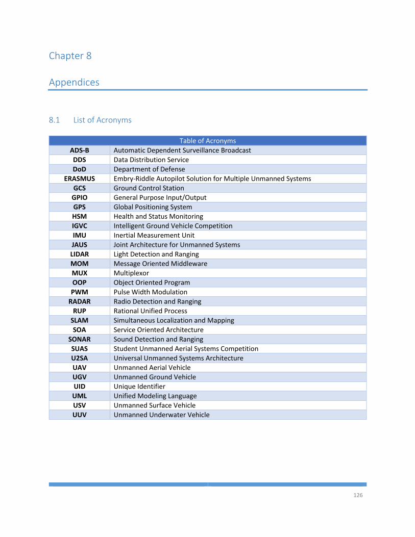
126
Chapter 8 Appendices
8.1 List of Acronyms
Table of Acronyms
ADS-B Automatic Dependent Surveillance Broadcast
DDS Data Distribution Service
DoD Department of Defense
ERASMUS Embry-Riddle Autopilot Solution for Multiple Unmanned Systems
GCS Ground Control Station
GPIO General Purpose Input/Output
GPS Global Positioning System
HSM Health and Status Monitoring
IGVC Intelligent Ground Vehicle Competition
IMU Inertial Measurement Unit
JAUS Joint Architecture for Unmanned Systems
LIDAR Light Detection and Ranging
MOM Message Oriented Middleware
MUX Multiplexor
OOP Object Oriented Program
PWM Pulse Width Modulation
RADAR Radio Detection and Ranging
RUP Rational Unified Process
SLAM Simultaneous Localization and Mapping
SOA Service Oriented Architecture
SONAR Sound Detection and Ranging
SUAS Student Unmanned Aerial Systems Competition
U2SA Universal Unmanned Systems Architecture
UAV Unmanned Aerial Vehicle
UGV Unmanned Ground Vehicle
UID Unique Identifier
UML Unified Modeling Language
USV Unmanned Surface Vehicle
UUV Unmanned Underwater Vehicle
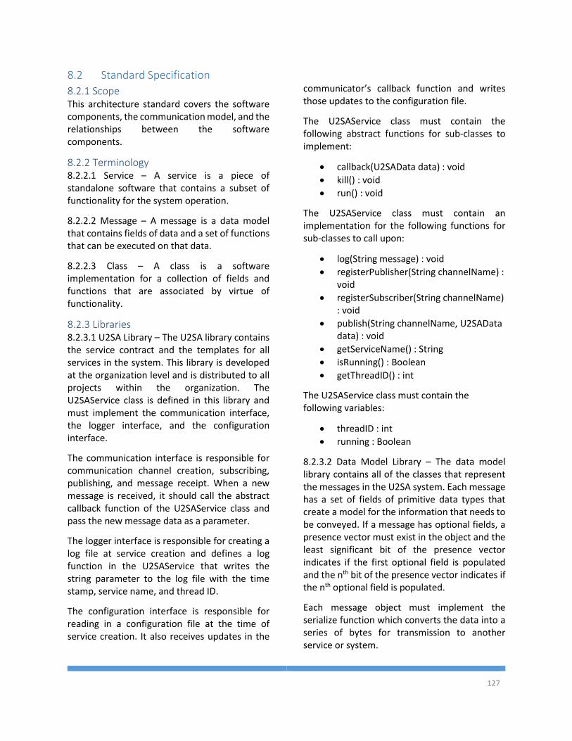
127
8.2 Standard Specification
8.2.1 Scope This architecture standard covers the software components, the communication model, and the relationships between the software components.
8.2.2 Terminology 8.2.2.1 Service – A service is a piece of standalone software that contains a subset of functionality for the system operation.
8.2.2.2 Message – A message is a data model that contains fields of data and a set of functions that can be executed on that data.
8.2.2.3 Class – A class is a software implementation for a collection of fields and functions that are associated by virtue of functionality.
8.2.3 Libraries 8.2.3.1 U2SA Library – The U2SA library contains the service contract and the templates for all services in the system. This library is developed at the organization level and is distributed to all projects within the organization. The U2SAService class is defined in this library and must implement the communication interface, the logger interface, and the configuration interface.
The communication interface is responsible for communication channel creation, subscribing, publishing, and message receipt. When a new message is received, it should call the abstract callback function of the U2SAService class and pass the new message data as a parameter.
The logger interface is responsible for creating a log file at service creation and defines a log function in the U2SAService that writes the string parameter to the log file with the time stamp, service name, and thread ID.
The configuration interface is responsible for reading in a configuration file at the time of service creation. It also receives updates in the
communicator’s callback function and writes those updates to the configuration file.
The U2SAService class must contain the following abstract functions for sub-classes to implement:
callback(U2SAData data) : void
kill() : void
run() : void
The U2SAService class must contain an implementation for the following functions for sub-classes to call upon:
log(String message) : void
registerPublisher(String channelName) : void
registerSubscriber(String channelName) : void
publish(String channelName, U2SAData data) : void
getServiceName() : String
isRunning() : Boolean
getThreadID() : int
The U2SAService class must contain the following variables:
threadID : int
running : Boolean
8.2.3.2 Data Model Library – The data model library contains all of the classes that represent the messages in the U2SA system. Each message has a set of fields of primitive data types that create a model for the information that needs to be conveyed. If a message has optional fields, a presence vector must exist in the object and the least significant bit of the presence vector indicates if the first optional field is populated and the nth bit of the presence vector indicates if the nth optional field is populated.
Each message object must implement the serialize function which converts the data into a series of bytes for transmission to another service or system.
128
The new message class must also have an implementation for the following functions:
serialize() : byte[]
8.2.4 Service Implementation To create a new service to execute within a U2SA system, a new class must be created that extends the U2SAService class located in the U2SA Library. A new service must then implement the abstract functions of the U2SAService class described above.
The kill function must be implemented in the service and must close out any open resources and set the ‘running’ variable to false.
Software that must run continuously is implemented in the run function of the new service. The run function should utilize the Boolean ‘running’ variable contained in the U2SAService class to determine if a loop should continue. Timing of the continuous software should be handled in the new service implementation.
Software that only executes as a response to the receipt of a message is implemented in the callback function. When the callback function is called, it should switch based on the type of the data message. Each of the generic messages defined in the U2SA that may be received by the service must be handled in the callback function. If more detailed messages are created for the application, they should be handled as a subset of the superclass that the message is built from. The callback function should also handle a default or else case so that if a message is received that is not handled, it is logged for debugging purposes.
8.2.5 Message Extension To create a new message object to add additional functionality to a U2SA system, the new message model must extend an existing message model or the U2SAData class.
To extend an existing message model, the new message model must add new fields to distinguish itself from the existing model. When
a service receives the new message model, it may treat it the same as the parent message model. This may occur if the service was not created to handle the new message model. This inheritance is necessary for backward compatibility.
Using the parent class’ functions through a super operator will allow the new message to add onto the existing functionality and inherit any changes made to the parent class.