designing quality learning spaces ... - ministry of …
TRANSCRIPT

DESIGNING QUALITY LEARNING SPACES
Indoor Air Quality and Thermal Comfort
Version 1.0, September 2017
Copyright 2017 Ministry of Education


Document history
The table below is a record of the changes that have been made to this document:
Revision date Version Summary of changes
September 2017 1.0 First version for general release:
amalgamates two 2007 Designing Quality Learning Space guidelines – Heating and Insulation, and Ventilation and Indoor Air Quality
substantial changes to content to reflect current teaching practise and flexible learning space design
document rewritten for a target audience of architects, designers and engineers involved in the design and specification of schools
Ministry requirements are now clearly marked as ‘mandatory’ or ‘recommendation’ to make them easy to find throughout the document.

Foreword
This document aims to ensure that the indoor air quality and thermal comfort of school buildings
supports quality educational outcomes. It does this by setting minimum requirements and
recommendations that must be considered when building or upgrading school buildings.
This document replaces two 2007 Designing Quality Learning Spaces (DQLS) guides: Heating and
Insulation, and Indoor Air Quality.
All projects that commence after 1 January 2018 must meet the DQLS – Indoor Air Quality and
Thermal Comfort requirements.
Background
The Ministry of Education (the Ministry) owns one of the largest property portfolios in New Zealand,
with more than 30,000 buildings in approximately 2,100 schools.
The way teachers and learners engage with each other has changed significantly in the last decade.
School design needs to reflect the changing needs of the users, and learning spaces must be
designed to support the way they are being used.
The DQLS series of guidelines were first released in partnership with the Building Research
Association of New Zealand (BRANZ) in 2007. The update of the DQLS series has been undertaken
to ensure the spaces that are built can support the many different styles of teaching and learning.
There have been substantial changes made in this update.
Indoor Air Quality and Thermal Comfort
Indoor air quality and thermal comfort have a direct impact on the usability of the space and on
learning outcomes. The technical guidance in this document has been developed from the latest
research and the review of school designs undertaken by the Ministry’s Design Review Panel.
Acknowledgement
The Ministry gratefully acknowledges the assistance of eCubed Building Workshop, the Ministry’s
Design Review Panel members and BRANZ in creating this document.
Feedback and updates
We are seeking to constantly improve the content and usability of our guidelines. If anything in this
guideline requires clarification please contact the Ministry through [email protected].
Your feedback will help us to ensure this document is maintained as a valuable resource for all of
those involved in the design of our schools as effective learning environments.
Kim Shannon
Head of Education Infrastructure Service

Contents
Introduction .......................................................................................................................................... 1
1 Requirements and Recommendations.................................................................................... 7
1.1 Indoor air quality and minimum fresh air ventilation requirements ........................................................7
1.2 Performance requirements .................................................................................................................................8
1.3 Ventilation design strategies ............................................................................................................................ 12
1.4 Indoor temperature levels, stability and control ......................................................................................... 13
1.5 Provisions for teacher monitoring and control of environmental conditions ..................................... 21
2 New Buildings .......................................................................................................................... 25
2.1 Introduction ............................................................................................................................................................ 25
2.2 Integrated passive design approach.............................................................................................................. 25
2.3 Building form ......................................................................................................................................................... 31
2.4 Orientation.............................................................................................................................................................. 31
2.5 Window to wall ratio, glazing and shading................................................................................................... 32
2.6 Thermal insulation ............................................................................................................................................... 33
2.7 Thermal mass ....................................................................................................................................................... 36
2.8 Pollutant control.................................................................................................................................................... 36
2.9 Ventilation design ................................................................................................................................................ 38
2.10 Natural ventilation strategies ............................................................................................................................ 41
2.11 Thermal comfort ................................................................................................................................................... 49
2.12 Design tools ........................................................................................................................................................... 51
3 Upgrading Existing Buildings ................................................................................................ 53
3.1 Indoor air quality ................................................................................................................................................... 54
3.2 Ventilation design ................................................................................................................................................ 56
3.3 Thermal insulation ............................................................................................................................................... 56
3.4 Thermal comfort ................................................................................................................................................... 57
4 Specialist Learning and Ancillary Spaces ............................................................................ 59
4.1 Halls and multipurpose spaces ....................................................................................................................... 59
4.2 Gymnasiums ......................................................................................................................................................... 62
4.3 Libraries .................................................................................................................................................................. 64
4.4 Music facilities ....................................................................................................................................................... 66
4.5 Science and technology spaces ..................................................................................................................... 68
4.6 Workshop technology spaces .......................................................................................................................... 70
4.7 Science spaces .................................................................................................................................................... 72
4.8 Server rooms and IT equipment cupboards ................................................................................................ 74
4.9 Toilets ...................................................................................................................................................................... 75
5 Components, Systems and Strategies.................................................................................. 76
5.1 Thermal performance of construction materials ........................................................................................ 76
5.2 VOC content and formaldehyde...................................................................................................................... 76
5.3 Window ventilation effectiveness .................................................................................................................... 77
5.4 Proprietary ventilation devices ........................................................................................................................ 77

5.5 Active heating/cooling systems ....................................................................................................................... 85
5.6 Building control systems .................................................................................................................................... 97
5.7 Lifecycle cost ......................................................................................................................................................... 97
5.8 Safety in design .................................................................................................................................................. 100
6 Glossary and References ..................................................................................................... 103
6.1 Glossary ................................................................................................................................................................ 103
6.2 Tables .................................................................................................................................................................... 109
6.3 Figures .................................................................................................................................................................. 109
6.4 References ........................................................................................................................................................... 111

Designing Quality Learning Spaces – Indoor Air Quality and Thermal Comfort 1
Introduction
Purpose
This document provides technical requirements and guidelines for the indoor air quality and thermal
comfort of school buildings in New Zealand. It provides guidance for design teams to plan and specify
fit-for-purpose schools, which may include the provision of new flexible learning spaces (FLS) that
support the creation of innovative learning environments (ILE) for schools to deliver the New Zealand
Curriculum and Te Marautanga o Aotearoa.
The principle focus of this new guideline is to outline new minimum requirements and
recommendations for indoor air quality and thermal comfort, and explain in detail the various factors to
consider to meet these requirements.
Intended audience
The DQLS series of guidelines are written for architects, designers and engineers involved in the
design and specification of New Zealand schools. They also provide relevant technical guidance for
property managers undertaking school projects.
The DQLS guidelines are also to be referred to by property professionals for the purpose of:
briefing design teams
informing and reviewing designs and specifications
estimating costs
undertaking Technical Post Occupancy Evaluations.
The DQLS guidelines set the performance requirements for new schools and the benchmark for
upgrading existing schools. The values given are intended to maximise the utility and flexibility of
learning spaces for all users. The guidelines aim to promote inclusive design and take into account the
general range of abilities and learning support needs expected to be found in New Zealand schools.
Learners with specific learning support needs may require provisions in addition to the requirements
set in the DQLS guideline series.
How to use this guideline
This document aims to be comprehensive in its guidance. For first time users, we recommend you
read all sections fully to get a broad overview.
When working on a specific project, we recommend the architect and heating and ventilation
engineers read Section 1 and Section 2 (in the case of new build projects), or Section 1 and Section 3
(in the case of upgrade projects).
If your project contains specialist learning spaces, gymnasiums, halls, libraries, and/or administration
spaces, then you will also need to read Section 4 to gain more specific guidance.
Section 5 provides detailed guidelines to assist heating and ventilation engineers in carrying out
system design and analysis. In addition to providing information on the heating and ventilation
performance of particular components and systems, Section 5 also provides guidance on lifecycle
costing and safety in design considerations.

2 Designing Quality Learning Spaces – Indoor Air Quality and Thermal Comfort
Document hierarchy
The Ministry is committed to providing quality learning spaces to enable education and learning in
schools to achieve the objectives of the Education Act 1989.
The Designing Schools in New Zealand (DSNZ) document is the overarching guidance for school
design. It states the Ministry’s policies for schools, the project design process and general principles to
be applied during planning and design. The DQLS guidelines support the DSNZ by providing detailed
performance requirements for refurbishing and creating new school buildings.

Designing Quality Learning Spaces – Indoor Air Quality and Thermal Comfort 3
Indoor air quality, thermal comfort and learning
School aged children have greater susceptibility to some environmental pollutants than adults
because they breathe higher volumes of air relative to their body weight, and their body tissue and
organs are actively growing. Children also spend more time in school than in any other environment
except home. Indoor air quality is dependent on the concentrations of CO2 and other respiration
derived pollutants, volatile organic compounds (VOC), particulate matter and other pollutants such as
formaldehyde.
The primary strategies for maintaining good indoor air quality are:
providing suitable ventilation with clean fresh air
selecting low VOC building materials; maintaining a good cleaning programme, and
using entry/exit mats to capture dust and dirt before they are brought into the building.
Children are also more sensitive to higher temperatures than adults, and they generally prefer
conditions to be a few degrees cooler due to their higher metabolic rates and higher activity levels
over the course of a school day.
In reality, what feels comfortable is not just related to air temperature, but also to relative humidity,
surrounding radiant temperatures, air movement, occupant activity levels and clothing worn. ‘Comfort’
inside naturally ventilated buildings has been found to be related to the prevailing outdoor
temperature, and in particular to the running average external temperature experienced in the
preceding few days. Comfort expectations of staff and students will adapt accordingly to this
experience of external temperature.
Figure 0.1 The connection between physical health, cognitive and mental well-being, and long-term academic
achievement (Credit: derived from the Schools for Health Program, Harvard T.H. Chan School of Public
Health).
Importance of indoor air quality and thermal comfort
The previous DQLS – Ventilation and Indoor Air Quality (2007) guidelines note that:
“Based on a survey carried out for the Ministry of Education by AC Neilson, teachers felt
ventilation and airflow was critical overall and that these were closely linked to their ability
to maintain control over the temperature in classrooms. Students also rated good
ventilation, along with having rooms that were not too hot or too cold, as important in
helping them to learn.”
Feeling
well
Biological and
physical health
Thinking
well
Short-term
cognitive and
mental wellbeing
Performing
well
Long-term
academic
success and
achievement

4 Designing Quality Learning Spaces – Indoor Air Quality and Thermal Comfort
A recent multi-level analysis of 153 classrooms in 27 primary schools in the UK, by Barrett et al.
(2015) identified the impact of physical classroom features on the academic progress of the 3,766
pupils who occupied those spaces. It identified seven key design parameters that together explain
16% of the variation in students’ academic progress. These design parameters were light,
temperature, air quality, ownership, flexibility, complexity and colour.
Figure 0.2 Relative contribution of key classroom design parameters to academic progress (Credit: derived from
Barrett et al., 2015).
Of the 16%, a third of the variation was due to indoor temperature and air quality.
Some of the principal findings of the study related to indoor temperature and air quality include:
unwanted sun heat is a problem where external shading is absent
large window size is not universally valuable in terms of students’ learning outcomes. Orientation,
shading control (internal and external), the size and positioning of windows all have to be taken
into account so that the risks of glare, over-heating and poor air quality can be avoided at the
design stage
students perform better where temperature control is easy
factors that affect CO2 concentrations are correlated with learning progress
students perform better in teaching spaces that have mechanical ventilation, large volume or large
opening windows.
The study also supports inside-out design that builds from a focus on user needs, and challenges the
visual dominance of much design effort.
Adapting to different teaching methods
The 2007 DQLS guidelines were focused on the traditional aspects of heating, insulation and natural
ventilation. These old guidelines were prepared when classrooms were more simple shapes with
shallower plan dimensions, and characterised by more structured and uniform occupation patterns.
Flexibility11%
Air Quality16%
Temperature12%
Ownership17%
Colour12%
Complexity11%
Light21%
Design parameters contributing to a
16% variation in academicprogress

Designing Quality Learning Spaces – Indoor Air Quality and Thermal Comfort 5
New schools are being designed with flexible learning spaces to enable innovative learning
environments, supporting a broader range of student learning needs and teaching practice. Flexible
learning spaces have different requirements in terms of environmental control due to their occupancy
patterns and flexibility. Deeper plans and lower ratios of perimeter wall area to floor area also change
ventilation and temperature control solutions. Occupation of large flexible learning spaces is generally
less uniform, with teacher and student use varying considerably both spatially and temporally, and
from inside to outside.
New buildings are being built better in terms of weathertightness, insulation and glazing standards.
Also in the last decade, a greater awareness of sustainable design and construction has resulted in a
focus on higher standards of indoor environmental quality, wellness and energy efficiency, and
greenhouse gas emissions.
In these new learning spaces design solutions for suitable thermal environments has switched from
needing heating to being at risk of overheating and from ventilation that works in summer only to year-
round ventilation. Designers are having to meet these new requirements whilst managing lifecycle
costs and environmental impacts.
Figure 0.3 An example of a flexible learning space. Multiple learning activities are taking place in different areas
with varying occupant numbers throughout the space.
DQLS Indoor Air Quality and Thermal Comfort - Overview
The DQLS - Indoor Air Quality and Thermal Comfort guidelines have been developed to set the
minimum standard for school buildings. Getting the indoor environment right is fundamental to
enabling students and teachers to be comfortable in their learning spaces. Providing good ventilation
rates and thermal control in learning spaces has been shown to support improved educational
outcomes and academic results.
In addition to the minimum requirements expected by the Ministry, this guideline offers best practice
recommendations intended to help users in setting priorities and making design decisions. A sample
of these requirements are:
occupied learning spaces are expected to have adequate ventilation to provide a minimum indoor
air quality range of 1000-1500 ppm CO2 (or less) over the course of the school day
indoor air temperatures within occupied learning spaces are expected to be within a range of 18˚C
to 25˚C for the majority of the year

6 Designing Quality Learning Spaces – Indoor Air Quality and Thermal Comfort
the lifecycle cost of plant and services providing appropriate air quality and thermal comfort are to
be resolved at the design stage, to enable good investment decisions to be made
teaching staff and students should be able to respond to internal air quality and temperature
information to manage their own internal environment.
Within this guideline:
Ministry requirements and key information are in RED, look for the symbol on pages where there
are mandatory requirements.
Ministry recommendations and other key concepts are in BLUE, look for the symbol on pages
where there are recommendations.
Integrated design philosophy
Designers are to apply an integrated design approach to the design of schools and learning spaces.
The usability of a space, acoustics, ventilation, daylight and energy use are interrelated and a change
to one factor often impacts other factors.
Figure 0.4 An integrated design approach is required to ensure quality learning spaces are optimised over all five
environmental parameters.
While all environmental factors need to be optimised, the following hierarchy is essential when making
value engineering decisions to meet the available budget for upgrades to existing buildings:
Usability of space > Acoustics > Ventilation > Daylight > Energy Use
For new buildings, the Ministry’s performance requirements must be met. For upgrades or
redevelopments, as near to the guidelines as reasonably practicable is expected.
A major upgrade would be expected to meet all or most of the requirements and recommendations,
whereas a minor upgrade should target specific requirements and recommendations where the works
involved are practically capable of achieving them.
Designing for good air quality with suitable thermal comfort will provide well ventilated buildings with
comfortable learning spaces.
-
3
7
Daylight
Usability of space
Ventilation (natural/mechanical)
Energy use (heating/cooling)
Acoustics
Optimising learning spaces
Designing Quality Learning Spaces – Indoor Air Quality and Thermal Comfort 7
SE
CT
IO
N 1
1 Requirements and Recommendations
The following section quantifies the Ministry’s minimum performance requirements for indoor air
quality and thermal comfort in schools. These performance requirements have been set to enable the
design and upgrade of schools to be in in line with the Ministry’s expectations on learning
environments. These spaces should support a variety of teaching and learning approaches, while also
providing adequate levels of comfort, and ensuring an environment conducive to good health and
wellbeing.
Designers will need to consider four key performance outcomes and associated control measures:
indoor air quality – Section 1.1
ventilation design – Section 1.2
indoor temperature range and control – Section 1.3
provisions for teacher and student monitoring and control of indoor air quality and temperature –
Section 1.4.
These minimum requirements ensure compliance with existing statutory obligations, and go beyond
the minimum standards required by the New Zealand Building Code (BC) to ensure appropriate
ventilation and temperature control are provided to support good education outcomes in our learning
spaces. These standards draw on a variety of relevant national and international best practice
standards and guides.
Local environmental factors will also have significant implications for all aspects of the building design.
Consideration of site-specific environmental factors is a key part of the design optimisation process,
and a key part of these requirements.
Designers should develop specific design solutions that ensure good and balanced performance
outcomes across all parameters.
1.1 Indoor air quality and minimum fresh air ventilation requirements
Indoor air quality is an important environmental measure that research suggests has a significant
impact on academic performance in schools. The Ministry wants to ensure adequate outdoor air is
provided to each learning space to ensure students and teachers can learn and work comfortably in
the space. The concentration of carbon dioxide (CO2) in the air is a good marker to check the general
indoor air quality. This is measured in parts per million (ppm).
The concentration of CO2 in outside air depends largely on the geographic location, air movement
effects (wind) and proximity to air pollutant sources (such as roads, heavy industry or geothermal
areas). Research suggests that normal urban atmospheric concentrations range from 450-600 ppm.
In enclosed spaces, normal respiration rates of occupants will naturally increase CO2 levels above
atmospheric levels. Figure 1.1 illustrates the relationship between indoor CO2 concentrations,
ventilation rates expressed both as air changes per hour (ACPH), as litres per second per person
(L/s/P), and various performance metrics (subjective occupant response, normalised student
performance and school absenteeism). The performance outcomes associated with CO2
concentrations and ventilation rates are based on findings from Barrett et al. (2015) and Chatzidiakou
et al. (2014).

8 Designing Quality Learning Spaces – Indoor Air Quality and Thermal Comfort
SE
CT
IO
N 1
1.2 Performance requirements
the average concentration of CO2 should not exceed 1,500 ppm when measured at seated head
height (1200mm), during the continuous period between the start and finish of teaching on any
day. An average of 1200 ppm or lower is required
the maximum peak concentration of CO2 should not exceed 3,000 ppm during the teaching day
at any occupied time, the occupants should be able to purge air to lower the concentration of CO2
to 1,000 ppm within 10 minutes
a purge threshold of 800 ppm or lower is recommended
a CO2 monitor with direct reading display is to be provided in a central location in each learning
space. This is to assist the teaching staff and students to manage CO2 by opening windows etc.
Refer to Section 1.4 for further details
provide appropriate local ventilation devices for specialist technology spaces. Refer to Section 4
for further details
for new or upgraded learning spaces, the building materials and components should be specified
to fall below the maximum allowable VOC-content, or the maximum allowable VOC-emission rates
as described by the New Zealand Green Building Council (NZGBC) Education Technical Manual
provide entry/exit mats at principal entry/exit points to mitigate dust and dirt tracking from outside
to inside.

Designing Quality Learning Spaces – Indoor Air Quality and Thermal Comfort 9
Figure 1.1 School indoor air quality, ventilation parameters and performance outcomes.Indoor air quality considerations.

10 Designing Quality Learning Spaces – Indoor Air Quality and Thermal Comfort
SE
CT
IO
N 1
CO2 concentrations for buildings naturally fluctuate over the day depending on the occupant load,
activities being performed and time of year. The ability of occupants to open and close doors and
windows will also affect the internal air quality. This can be seen in the following two figures which
illustrate the typical pattern and significant variability of CO2 concentrations.
i
Figure 1.2 An example of measured CO2 concentrations (ppm) for a naturally ventilated flexible learning space in
Auckland over one week period during winter.
Figure 1.3 An example of measured CO2 concentrations (ppm) for a naturally ventilated flexible learning space in
Auckland during a winter’s day.
10 minute purge
threshold of 1000 ppm
Maximum daily
average 1500 ppm
Actual daily average
1220 ppm
Maximum daily limit
3000 ppm

Designing Quality Learning Spaces – Indoor Air Quality and Thermal Comfort 11
SE
CT
IO
N 1
CO2 concentrations
In Figure 1.2, CO2 concentrations rise and fall over the course of a typical day and follow a similar
pattern over the week.
In Figure 1.3, CO2 concentrations rise from a base of 400 ppm (equivalent to external atmospheric
CO2 concentrations) to peak of ~2,200 ppm at around 11am. CO2 concentrations then drop over the
lunchtime period before rising again to a secondary peak of ~1000 ppm around 3pm. Being winter,
windows and doors are generally closed first thing in the morning to conserve heat. Over the course of
the day windows and doors are opened as occupants move between indoor and outdoor learning
environments, or in response to feelings of stuffiness as CO2 concentrations, temperature and
humidity increase.
By way of context, the NZ Workplace Exposure Standards specify an average CO2 concentration limit
of 5,000 ppm over the course of an eight hour day and a five day working week (the Time Weighted
Average limit – TLV-TWA). The specified short-term exposure limit is 30,000 ppm over any 15 minute
period (TLV-STEL).
CO2 and other respiration derived pollutants
CO2 is recognised as a useful proxy for respiration derived pollutants (including airborne pathogens
and anthropogenic odours1). Due to the range of sources and types of possible pollutants, it is difficult
to define an acceptable threshold for all indoor pollutants. In typical non-specialist learning
environments general pollutant levels may be reasonably characterised by the amount of CO2 in the
air. The CO2 concentration limits set out above are intended to serve as a limiting proxy for a range of
other airborne pollutants.
The available evidence indicates that even the highest CO2 concentrations likely to be encountered in
learning spaces in schools would not in themselves constitute a risk to health, but rather a temporary
impediment to cognitive performance, particularly in relation to speed.
Particulate matter
Particulate matter (PM) is an air-suspended mixture of solid and liquid particles from both human and
natural sources. PM is normally classified by size (PM10 includes particles of <10 μm diameter, and
PM2.5 <2.5 μm). PM10 particles are coarser. Due to their size, they can be intercepted and filtered by
the nose and throat. Finer PM2.5 particles may pose a greater risk than PM10 particles as they can
penetrate into the deepest parts of the lung. Studies in schools have shown that roughly half the
sources of PM2.5 particles comprise of: soil particles tracked in from outside2, a mix of organic material
from ”personal clouds” comprising skin flakes and other bio-effluents, clothing fibres, possible
condensation of VOCs, and calcium particles from chalk and building deterioration. The other half
comes from outside and includes minerals from hard surfaces and from road traffic.
Generation and re-suspension of these particles is a function of indoor/outdoor movement and activity
levels in the learning space. Indoor levels can be two to five times higher than outside, and sometimes
significantly higher.
Consider strategies to reduce PM levels, including good ventilation, using well-maintained HEPA
vacuum cleaners, and the use of entry/exit mats to mitigate dirt tracking inside.
1 Chatzidiakou (2014), p. 170
2 Rovelli et al. (2014); Alves et al. (2013); Fromme et al. (2008)

12 Designing Quality Learning Spaces – Indoor Air Quality and Thermal Comfort
SE
CT
IO
N 1
Volatile Organic Compounds
A wide range of VOCs and other potentially harmful substances may be emitted by building materials,
furnishings and appliances. These are of particular concern in new or recently refurbished and
refurnished buildings, as VOC emissions are typically highest from new products and diminish over
time. Concentrations of these pollutants may be controlled through the specification of low VOC-
content products, and through the specification of adequate ventilation strategies and temperature
ranges1.
There is evidence to suggest that maintaining classroom temperatures below 26°C (and preferably
below 22°C) may also reduce VOC concentrations2. CO2 concentrations may be a poor proxy for
these types of pollutants, particularly in the context of new or recently refurbished and refurnished
buildings. However, the broad range of specific compounds, variable toxicities, and wide variety of
VOC sources make this class of pollutants difficult to set standards for effectively and completely.
Pollutants in specialist learning spaces
A wide range of other pollutants may be encountered in specialist learning spaces such as
laboratories, workshops and art studios. These are discussed in Section 4.
1.3 Ventilation design strategies
Ventilation may be provided through either natural or mechanical means. The strategy employed will
depend on the form of the school building, its size, occupancy density, acoustics and other site
specific requirements. Wherever practical, natural (passive) or semi-natural (passive) ventilation is
preferred by the Ministry, provided minimum requirements in terms of pollutant control, and
temperature level stability and control, are met.
Natural ventilation entails the provision of windows and other vents that may be manually opened and
closed. Natural ventilation is usually associated with smaller, spatially simple enclosures, but can be
an effective strategy in larger spaces with careful modelling and specific design. Natural ventilation
relies on internal-external air pressure differentials, or on vertical thermal differentials within building
spaces (the ‘stack effect’), to drive air movement.
Mixed natural/mechanical and wholly mechanical ventilation is suited to larger, spatially complex
enclosures with moderate to high occupancy levels. Mechancial ventilation may also be appropriate
for internal rooms in deep plan buildings, or where acoustic requirements preclude the use of natural
ventilation.
Different design principles govern each strategy; they are addressed separately below.
Natural ventilation (passive)
Minimum outdoor ventilation rates nominally equivalent to four air changes per hour, providing
approximately eight litres per second per person, will be considerably exceeded by opening windows
in warmer weather. It is expected that the summer range of CO2 levels will vary from approximately
400 ppm to 1,000 ppm over the course of a day. Maintaining good indoor air quality in naturally
ventilated buildings during cold weather is more difficult and relies, to a certain extent, on staff
intervention to open windows, as described in Section 1.4.
1 Chatzidiakou (2014), p. 175
2 Ibid., pp. 168, 175; Kagi et al., (2009)

Designing Quality Learning Spaces – Indoor Air Quality and Thermal Comfort 13
SE
CT
IO
N 1
In warm climate zones, the provision of trickle vents and a range of window opening arrangements
with a CO2 monitor, can meet the requirements of Section 1.1.
Mixed natural/mechanical ventilation
Natural ventilation arrangements are to be supplemented by additional powered or non-powered
supply/exhaust systems with variable flow capability linked to CO2 automatic control where buildings
have:
deeper plan
single sided ventilation that cannot be naturally ventilated adequately
complex building shapes with airflow deadspots.
Also consider spaces such as breakout areas where doors may be closed during a classroom session.
In cold climate zones where natural outdoor air ventilation may result in cold draughts and discomfort,
mechanical heat recovery or mixed-mode ventilation is to be considered.
Mechanically ventilated
Where natural outdoor air ventilation is precluded, a filtered mechanical outdoor air ventilation system
is to provide the minimum flow rates as per NZS 4303:1990 Ventilation for acceptable indoor air
quality or AS 1668.2:2012 Mechanical ventilation in buildings, and as per the particular Ministry
requirements given in Section 4.
For example, for schools in cold climate zones where natural ventilation would result in cold draughts,
for internal rooms, for acoustic reasons, for external pollutant reasons, or because the spaces are of a
specialist nature with specific ventilation requirements as described in Section 4.
1.4 Indoor temperature levels, stability and control
Overheating, rather than underheating, is the key concern in new schools due to better building
insulation and airtightness, particularly in schools without active cooling. Evidence indicates that
children attending schools in temperate climates may be more sensitive to higher temperatures than
adults and that they generally prefer conditions to be a few degrees cooler due to their higher
metabolic rate and activity levels over the course of a school day.
Figure 1.4 below indicates that if higher temperatures over summer are present in the learning space,
they may have a reasonably significant effect on student performance, particularly in terms of
cognitive speed. However, in practice these elevated temperatures may only persist for a few hours a
day during warmer weather.
Indoor temperature should remain within a comfortable range throughout the school day. However,
what feels comfortable will vary according to the time of day, relative humidity, radiant temperatures,
occupant activity levels, air movement, and individual preference. There are a number of artificial
comfort or operative temperature equivalents that attempt to consider all these factors.
The subjective comfort levels reported by occupants in free running naturally ventilated buildings
without recourse to air conditioning have also been found to be related to the prevailing outdoor
temperature, and in particular to the running average in the preceding few days. In simple terms,
higher internal temperatures become more tolerable to occupants during sustained periods of warm
weather.

14 Designing Quality Learning Spaces – Indoor Air Quality and Thermal Comfort
SE
CT
IO
N 1
This adaptive concept of comfort relies on the occupants being able to adapt their space and clothing,
for example:
opening windows for increased air movement
operating blinds to block out sun or providing external sun shading
switching on ceiling fans
wearing lighter clothing in summer
having regular access to drinking water.
Models have been developed by both ASHRAE (ANSI/ASHRAE Standard 55) and CIBSE (CIBSE
TM52) that take into account all the above factors in a holistic way. Their application is fairly complex
to evaluate, although available computer software can automate this task. The CIBSE version TM52
also relies on the development of Design Summer Year (DSY) files rather than the Typical
Meteorological Year (TMY) files commonly available in New Zealand.
For this reason, a modified version of the more established performance standards given in the CIBSE
Guide Book A, and in the UK Building Bulletin 101 – Ventilation of School Buildings has been used as
the basis of the Ministry’s requirements. These standards have been modified by the use of modelling
in different New Zealand locations to determine locally appropriate hours of exceedance values. They
use fixed air temperature rather than variable adaptive temperature as a metric.
If DSY files are developed for New Zealand locations, then the use of CIBSE TM52 as an alternative
overheating standard at the design stage is considered acceptable.
Minimum temperature requirements
all learning spaces (except gymnasiums) are to be provided with a heating system sufficient to
maintain a minimum temperature of 18˚C during normal periods of occupation, measured at a
height of 1m above floor level
administration, resource work and meeting spaces, and staffrooms are to be provided with a
heating system sufficient to maintain a minimum temperature of 20°C during normal periods of
occupation, measured at 1.5m above floor level
spaces such as corridors and multipurpose halls and gymnasiums are to be provided with a
heating system sufficient to maintain a minimum temperature of 16°C during normal periods of
occupation, measured at a height of 1.0 m above floor level
provision for heating Universal School Bathrooms (formerly High Dependency Units) is required,
so that these rooms can be heated to 22°C
the use of radiant panel type heaters is recommended for Universal School Bathrooms
toilets and change rooms are not required to be heated.
Heating system recommendations
Heating systems are to be appropriate to the climate zone and the longterm availability of fuel/energy
sources. A lifecycle costing/options report is required as described in Section 5.7.
Systems that could be considered include:
central boiler systems in conjunction with low surface temperature radiators, underfloor heating or
warm air fan coils. Consider alternative and available fuel sources, eg natural gas and wood
chip/pellet. New coal-fired, fuel, oil, electric, and LPG boiler installations are to be avoided
air or ground source hot water heat pump along with underfloor heating or warm air fan coils
electric radiant heating

Designing Quality Learning Spaces – Indoor Air Quality and Thermal Comfort 15
SE
CT
IO
N 1
reverse cycle, split air conditioning heat pumps
reverse cycle multi split, variant refrigerant flow (VRF) air conditioning systems
packaged ducted air conditioning systems.
Each principal activity space is to be capable of individual zone temperature and time control. It should
be possible to override the time control to provide additional heating in each space by the provision of
afterhour switches to allow for pre and after school use of individual spaces.
Maximum internal temperature requirements
Schools are to be designed to ensure overheating does not occur.
Overheating can cause thermal stress to occupants and creates uncomfortable indoor environments.
Overheating is most likely to occur during summer months for the occupied period of 9am to 3:30pm,
Monday to Friday. For design modelling purposes, summertime is between the dates 10 October to
20 December, and 1 February to 15 April (school terms 4 and 1 respectively).
To show that the proposed school building will not suffer overheating, learning spaces, libraries,
administrative offices, staffrooms and multipurpose spaces are to be designed to comply with at least
two of the following three criteria:
(1) there should be no more than the number of hours given in Table 1.1 when the air temperature
in the classroom rises above 25°C and 28°C
(2) the average internal to external temperature difference should not exceed 5°C (ie the internal air
temperature should be no more than 5°C above the external air temperature on average over a
day during school hours)
(3) the internal air temperature when the space is occupied should not exceed 32°C.
Criteria notes
Gymnasiums and ancillary spaces are excluded from these criteria. However, good thermal design
principles should still be applied.
Condition (1) describes the amount of time that overheating above a desirable maximum
temperature of 25°C and to an elevated temperature of 28°C. The latter temperature indicates the
upper limit of internal temperature that is considered both hot and uncomfortable.
Condition (2) ensures that the change in temperature staff and students experience moving from
outside to inside remains within tolerable limits. The lower the value the more desirable. 5°C
represents the upper threshold.
Condition (3) describes the maximum temperature of 32°C above which it is highly undesirable to
exceed.
The designer is to demonstrate within a project’s preliminary or developed design report that the
maximum summertime temperature requirements described above will be met for learning spaces and
multipurpose spaces only.
For simple building forms, provision of a design statement and any supporting calculations will be
sufficient (types 1A, 2A and 1B, as described in Figure 2.8).
For more complex building forms, the design statement is to be supported by a thermal modelling
report (types 2B and 2C, as described in Figure 2.8).

16 Designing Quality Learning Spaces – Indoor Air Quality and Thermal Comfort
SE
CT
IO
N 1
Cooling requirements
In naturally ventilated spaces, high summertime temperatures can be mitigated by low-noise variable-
speed ceiling sweep fans.
The cooling effect of these local fans can be equivalent to reducing the perceived comfort temperature
by around 2°C.
Ventilation openings should have a combined area of between 7.5 to 10% of the floor area.
The representative window area being the total face area of the openable vents and assuming an
aerodynamic area coefficient of approximately 50%. Modelling can provide a more accurate
assessment of the aerodynamic areas of differing window types.
If vents are more constricted than this then the percentage area of openable vents to floor area should
be increased on a pro-rata basis. The ventilation area should be well distributed, ideally with high and
low level openings, and wherever possible are to be configured to avoid stagnant air pockets.
Reliance on opening doors as the predominant means of natural ventilation should be minimised.
Preference is given to more operable and controllable vents and windows, which should provide a
range of ventilation openings suitable for different times of the year.
Active cooling system recommendations
Where it can be demonstrated by modelling that the summertime temperature criteria given in (1)
above cannot be reasonably achieved by natural ventilation and good passive design, then
mechanical ventilation may be considered as more appropriate for summertime temperature control.
This is more likely to be the case for new school buildings in locations with warmer summer
temperatures (Northland, Auckland, Hawkes Bay, Nelson/Blenheim and Christchurch).
Some specialist spaces should always be provided with active cooling as described in Section 4.
Other administrative spaces that require high levels of acoustic privacy may be provided with cooling
at the discretion of the Ministry and the school.
Energy efficiency for both the energy consumed in circulating air, and the energy consumed in
heating/cooling should be of concern to designers. Careful analysis is required in order to provide
justification on a school-by-school basis.
Appropriate use of a HVAC system may also include:
sites that are affected by high levels of road or air traffic noise, or that generate significant noise
themselves (eg music rooms or workshops)
sites that are exposed to high levels of pollen or other outside air contaminants may also require
mechanical ventilation and filtration
school building forms with excessively deep spaces where natural ventilation may not be feasible
spaces of a specialist nature, eg performing arts centres
buildings where the amount of air required for summertime temperature control are large, and
analysis deems it inefficient and costly to operate heating/cooling separately.
Where an HVAC system is required and agreed by the Ministry, then the system is to be sized and will
operate with set points 2°C below the NIWA 1% summer dry bulb design temperature (ie if the NIWA
1% summer design temperature is 27°C, the system is to be designed and operated to maintain
25°C).

Designing Quality Learning Spaces – Indoor Air Quality and Thermal Comfort 17
SE
CT
IO
N 1
Allowances are also to be made for adjusting the current NIWA 1% design criterion for increased
incidence of extreme conditions as predicted by Ministry for the Environment’s climate change
projections. HVAC systems to be considered include:
reverse cycle split air conditioning heatpump in conjunction with minimum CO2 controlled outdoor
ventilation system, with or without heat recovery depending on climate zone
reverse cycle multi split or hybrid VRF air conditioning systems in conjunction with minimum CO2
controlled outdoor ventilation system, with or without heat recovery depending on climate zone
all air packaged air conditioners with ducted supply and return/spill air complete with economiser
cycles and CO2 controlled minimum outside air control.
The choice of HVAC system may be subject to a lifecycle cost benefit analysis, as described in
Section 5.7.

18 Designing Quality Learning Spaces – Indoor Air Quality and Thermal Comfort
Figure 1.4 School Indoor Temperature Parameters. For allowable hours above 25˚C (Threshold 1) and 28˚C (Threshold 2) refer to Table 1.1

Designing Quality Learning Spaces – Indoor Air Quality and Thermal Comfort 19
SE
CT
IO
N 1
Table 1.1 Allowable hours above 25°C and 28°C for New Zealand schools in specified locations during the
occupied period of 9am to 3:30pm, Monday to Friday from 10 October to 20 December, and 1 February
to 15 April.
Climate zone Sub zone towns/cities*
No. of hours above
25ºC 28ºC
North Island 1 – Warm
Northern North Island Kaitaia, Whangarei, Auckland 250 50
North Island 2A – Cool
Central North Island Hamilton, Rotorua 150 10
South West North Island New Plymouth, Whanganui, Palmerston North, Wellington
150 10
North Island 2B – Warm
Eastern North Island Gisborne, Napier, Hastings, Masterton 250 60
North Island 3A – Cool
Central North Island Taupo 150 10
South Island 3B – Warm
Northern South Island Nelson, Blenheim 150 20
South Island 3C – Cold
Western South Island Westport, Hokitika, Greymouth 50 10
Eastern South Island Kaikoura, Christchurch, Timaru 150 40
Inland South Island Wanaka, Queenstown, Alexandra 50 10
Southern South Island Dunedin, Invercargill 20 10
*For demarcation of climate zones and sub-zones see Figure 1.5.

20 Designing Quality Learning Spaces – Indoor Air Quality and Thermal Comfort
SE
CT
IO
N 1
Figure 1.5 New Zealand climate zones and sub-zones.

Designing Quality Learning Spaces – Indoor Air Quality and Thermal Comfort 21
SE
CT
IO
N 1
Climate change effects
The Ministry for the Environment’s Climate Change Projections for New Zealand (2016) concludes
that climate change effects will result in higher temperatures, with greater increases in the North Island
than in the South, with the greatest warming in the North East. The amount of warming in New
Zealand is likely to be lower than the global average. Warming will be greatest in the summer season,
and least in winter and spring.
Temperature extremes are anticipated to change significantly by the end of the century, with maximum
temperatures of 25˚C or more predicted to double or quadruple in frequency. The Ministry’s
overheating criteria requirements are therefore likely to change over time, with greater reliance on
active cooling in warmer regions. This response should be viewed in conjunction with the anticipated
lifecycle of heating/cooling systems, typically 15 to 25 years, and also with the need to minimise
greenhouse gas emissions in the short to medium term.
1.5 Provisions for teacher monitoring and control of environmental conditions
In naturally ventilated and passively controlled learning spaces, teaching staff and students have a key
role in maintaining the CO2, ventilation and temperature requirements given in Sections 1.1, 1.2 and
1.3. However, teachers are busy performing their pedagogic role and are sometimes uncertain of their
role in maintaining conditions in the classroom. Research suggests that teachers frequently
underutilise windows, resulting in inadequate ventilation5. It is also recognised that maintaining a
healthy and comfortable internal environment is a good life skill for students to acquire.
Operation of windows and doors in learning spaces needs to be as simple and intuitive as possible,
and should be supported by good information regarding when to open doors and windows, and by
how much.
Allocation of the responsibility for opening windows becomes more complex in flexible learning spaces
which are shared by a larger number of students and teaching staff. Their interconnecting spaces also
raise the potential for disrupting cross-ventilation. Consideration should therefore be given to the
extent to which students should be able to control ventilation rates.
Ministry requirements
Provide CO2 and internal/external temperature display in a central location within each learning space,
with instant visible feedback to local users. This is to be provided with either:
a) a simple laminated or framed user guide adjacent to the display. A simplified example is given
in Figure 1.8. Note that this must be altered as appropriate to suit the specific design of the
teaching spaces; or
b) an electronic display device to be used with inputs from the CO2 and internal/external
temperature monitors, with a graphic display of actions required by users.
Educate and require the teaching staff to appoint student monitors in each learning space to take joint
responsibility for looking at the temperature and CO2 levels at the start and finish of each school
period, setting the windows/vents, and operating the ceiling fans accordingly.
5 Gully (2015), p. 29; Liaw (2015), Table 13, pp. 37-38

22 Designing Quality Learning Spaces – Indoor Air Quality and Thermal Comfort
SE
CT
IO
N 1
Figure 1.6 Combined inside/outside temperature, CO2 (ppm) and relative humidity display device.

Designing Quality Learning Spaces – Indoor Air Quality and Thermal Comfort 23
Figure 1.7 Interactive control display.

24 Designing Quality Learning Spaces – Indoor Air Quality and Thermal Comfort
Figure 1.8 Teacher window position and ceiling fan matrix to be reviewed at start and finish of each period/lesson. Actual settings will depend on ambient wind and noise
conditions
Designing Quality Learning Spaces – Indoor Air Quality and Thermal Comfort 25
SE
CT
IO
N 2
2 New Buildings
2.1 Introduction
This section covers design considerations relevant to new learning environments. It explains how the
Ministry’s requirements and recommendations set out in Section 1 apply to new buildings, and
includes a range of potential strategies and design solutions.
Heating, ventilation and cooling design must meet the Ministry’s minimum requirements as specified in
Section 1 as well as any relevant requirements contained in other DQLS guidelines. Designers will
need to apply an integrated approach to the design of schools and the learning spaces within them.
Acoustics, temperature control, ventilation, lighting and energy use are all interrelated, and a change
to one environmental factor may impact on others. This guideline should be read in conjunction with
other guidelines in the DQLS suite.
Heating, ventilation and cooling design must also meet the overarching requirements set out in the
Ministry’s Designing Schools in New Zealand - Requirements and Guidelines along with Ministry
requirements of efficiency, durability and cost effectiveness.
The selection of heating, ventilation and cooling strategies, and of specific plant and building
components, should be informed by a careful comparative analysis of the lifecycle costs and benefits
of the competing options. Further requirements with regard to lifecycle costs and the comparative
benefits for heating, ventilation and cooling systems are given in Section 5.7.
2.2 Integrated passive design approach
With traditional design processes, when just 10% of a project’s cost has been expended, 70 to 80% of
the lifetime costs and consequences of the building will have been effectively locked in. An integrated
whole building design process develops an overall building design by workshopping a range of design
options and solutions that offer positive outcomes across all design disciplines: architectural,
structural, services, acoustics, fire etc.
Integrated design
Integrated design brings together the various specialist disciplines that contribute to the overall design
process of a building or project. For new school projects, collaboration between specialist design
disciplines should ideally occur early in the design process, at the master planning and preliminary
design stages. Integrated design seeks to exploit available synergies between different design
disciplines and to avoid conflicts between the various design strategies developed by each discipline.
Integrated design plays a key role in maximising indoor environmental quality and energy efficiency
across the range of relevant building services.

26 Designing Quality Learning Spaces – Indoor Air Quality and Thermal Comfort
SE
CT
IO
N 2
Figure 2.1 Integrated design process.
Further guidance can be found in the Ministry for Environment’s Integrated Whole Building Design
Guidelines.
Passive design
Passive design seeks to adopt design strategies that take advantage of local environmental and
climatic conditions. A principal aim of passive design is often to minimise the building’s energy use.
Passive design strategies may be employed across the range of specialist design disciplines including
lighting, acoustics, heating/cooling and ventilation. Passive design strategies frequently involve more
than one specialist design discipline – a passive temperature control strategy, for example, may have
implications for lighting, ventilation and structural design. Good passive design usually requires an
integrated design process, as described above, that brings together all of the specialist disciplines that
contribute to the overall design of a building or project.
In order to adapt to – and exploit – the local site characteristics, it is important that a thorough
understanding be gained of the site’s environmental and climatic conditions. A detailed study of the
site’s environmental and climatic features, including a site specific load chart similar to that presented
in Figure 2.2, should form a key input into the master plan and preliminary design stages of projects.
Important elements of passive design include building location, form and orientation, internal layout,
window design, thermal resistance of the building envelope, distribution of thermal mass within the
building, external shading of the building and passive ventilation design. Each of these elements
should complement the others in order to achieve comfortable temperatures, good indoor air quality,
good acoustics, good natural light and a high degree of energy efficiency.
Building design features can either support or present challenges to the achievement of passive
design goals. Building design features that particularly affect passive temperature control and natural
ventilation are highlighted in Table 2.1.

Designing Quality Learning Spaces – Indoor Air Quality and Thermal Comfort 27
SE
CT
IO
N 2
Table 2.1 Key design features affecting the success of passive temperature control and natural ventilation.
Success factors Problem issues
Shallow plan building design Deep plan building design
Two-sided façade and uninterrupted airflow Single-sided and cellular narrow plan
High ceilings Low ceilings
Thermally heavyweight construction Thermally lightweight construction
Well designed and distributed windows with a range of opening options, suitable for use in changing external conditions
Poorly designed and distributed windows
High efficiency LED lighting and equipment Low efficiency lighting and equipment
Low external noise levels; controlled indoor ambient noise levels
High external noise levels; uncontrolled indoor ambient levels
Solar gain and inside/outside heat transfer are significant sources of incidental heat in most learning
environments. In general terms, solar gain and ambient heat sources add an average of 25 watts per
square metre (W/m2) on a relatively sunny day with reasonable solar control.
There are other significant sources of heat that should be considered during the passive thermal
design process. Students and teachers may generate in the vicinity of 60 to 80 watts of heat energy
respectively when seated. This is equivalent to 30 W/m2 of peak heat gain released into the learning
environment.
The increasing use of personal electronic devices, such as laptpops and tablets, also results in a large
number of small heating sources distributed throughout the learning space. Although the power
demand of these devices is falling, their prevalence is only likely to increase. Other electronic
appliances such as printers, projectors and TV screens can also generate significant amounts of heat.
Specification of low-energy appliances may help to reduce overall energy use, while also lowering the
extent of overheating or the need for active cooling during summer months.
The potential for lighting efficiency continues to improve, particularly with the use of T5 fluorescent and
LED lamps, and through occupancy controls. Perimeter lighting can also be circuited to allow it to be
switched off when adequate daylight is available. Lighting can release around 6 W/m2 of heat energy
into the learning environment.
Averaged over the whole day, a learning space might expect an average heat load of 40 to 60 W/m2,
which is released as heat into the learning environment.
Load charts are a good way to look at the effects of these heat gains. They are a simplified graphical
plot of average heat gain against outside air temperature. Typical load charts for Auckland and
Dunedin learning spaces are presented in Figure 2.2 and Figure 2.3, respectively.
The maximum heat loss/minimum heat gain line is for an unoccupied space and represents the
building fabric and infiltration loads only. It crosses the outside temperature axis at the winter design
temperature balance point of 18°C, and at the winter design temperature the load represents the
design winter heat loss. The minimum heat loss/maximum heat gain line includes all the effects of
occupants, lights, equipment, solar, fabric and infiltration for an occupied space. When these loads are
taken into account it can be seen from the chart that the balance point shifts downwards from 18°C to
9°C. This means that whenever the outside air temperature is above 9°C and the learning space is
occupied, it does not require any heating, and that overheating may start to occur at outside
temperatures of around 18°C.

28 Designing Quality Learning Spaces – Indoor Air Quality and Thermal Comfort
SE
CT
IO
N 2
What the load chart indicates is that occupied learning spaces can heat up when subject to solar gain
and internal heat gains. Although heating may be required early in the morning during spring and
autumn to achieve the minimum required temperatures, overheating may quickly become an issue as
the outside temperature rises (especially if inclement weather deters the opening of windows). A
building may therefore need to shift into a passive cooling mode, particularly in warmer climate zones.
In well insulated schools, overheating, rather than underheating, is therefore the critical design driver
for most of the school year in the majority of New Zealand school locations. Designers should consider
ways to moderate any detrimental effects and ensure that excess heat can be vented when required.
Passive cooling of larger spaces to mitigate these heat gains is primarily provided through wind driven
cross-flow ventilation via opening windows.
Thermally-driven passive (or ‘stack’) ventilation may also be provided, particularly if the space has
sufficient height to support a robust stack effect. This can be particularly helpful on hot, still days.
Other passive cooling strategies may include:
minimising excess solar gain (through window design, placement and shading)
insulation to prevent heat gain
thermal mass to absorb excess heat (with stored heat vented at night, or utilised in the early
morning)
use of eaves or external shading devices, such as sun screens or deciduous trees, to control solar
gain
internal blinds to mitigate the effects of direct sunlight on teaching staff and students close to
windows.

Designing Quality Learning Spaces – Indoor Air Quality and Thermal Comfort 29
Figure 2.2 An example thermal load chart for Auckland, showing load variation over the course of a year. As average internal heat gains from various sources increase (solar,
occupants, lighting, etc.), so must the number of passive design features as indicated in the margin to the right of the chart.

30 Designing Quality Learning Spaces – Indoor Air Quality and Thermal Comfort
Figure 2.3 An example thermal load chart for Dunedin, showing load variation over the course of a year. As average internal heat gains from various sources (solar, occupants,
lighting, etc.) increase, so must the number of passive design features as indicated in the margin to the right of the chart.

Designing Quality Learning Spaces – Indoor Air Quality and Thermal Comfort 31
SE
CT
IO
N 2
2.3 Building form
The form of the building can have a significant effect on the internal environment and on the utilitsation
of passive energy sources such as natural ventilation and natural light. Generally, narrow building
forms allow greater utilization of natural ventilation and natural light. Single storey buildings also allow
the roof design to be utilized more fully in deeper plan spaces. However, the building should not be so
narrow that the learning environment is compromised. As a general guideline, 12-14m spans provide
good levels of internal flexibility whilst still enabling good neutral levels of ventilation and daylight.
The environment in the lower storey of two storey buildings is generally easier to control than the
upper storey.
As building forms become deeper, more complex and more subdivided internally, reliance on passive
approaches becomes increasingly challenging.
The pros and cons of differing building forms with particular regard to ventilation design are discussed
further in Figure 2.8. Similar justifications can be made for availability of natural light.
For larger learning spaces, increased building heights and volumes can help to stratify heat and
encourage a robust stack effect and to assist in cross ventilation.
The ratio of height to depth is an important factor in natural ventilation design.
2.4 Orientation
Where feasible thorough site planning, large elevations of east and west facing glass should be
avoided in order to control and prevent associated glare and solar gain issues. Windows orientated to
the north and south are easier to shade.
An ideal orientation generally lies between +/- 30° North.
Figure 2.4 Building orientation shading to help manage solar gain.
This orientation minimises shading requirements and maximises the efficiency of any shading devices
used.
Windows should also be oriented away from busy roads/streets wherever possible to minimise the
effects of noise and pollutants on the internal environment.

32 Designing Quality Learning Spaces – Indoor Air Quality and Thermal Comfort
SE
CT
IO
N 2
2.5 Window to wall ratio, glazing and shading
Although light is a key design parameter, window size alone is not significantly correlated with learning
outcomes. Only when orientation, risk of glare and overheating are taken into consideration, can
students benefit from optimum glazing size. The effects of shortwave solar radiation from sunshine
falling on a person can elevate the perceived air temperature by 4 to 5°C.
The average window area should be around 30 to 50% of the wall area. Window areas should be
concentrated across the southern, northern and eastern elevations (subject to appropriate shading).
Large windows to the west should be minimised.
A wide selection of glazing is available, variously designed to maximise acoustic insulation, minimise
transmitted solar gain, maximise thermal insulation, or some combination thereof. Two useful rating
values for glazing are the solar heat gain coefficient (SHGC) and thermal resistivity (R-value).
Shading coefficients range from above 0.82 for uncoated clear single pane glass, to less than 0.60 for
double glazing with a low emissivity pane and argon gas fill.
There is a preference in schools for the use of clear (or at most, lightly tinted) glass with a light
transmittance >70% (in conjunction with shading where necessary). Reflective or heavily tinted glass
should be avoided.
Additional shading can be provided in a variety of architectural ways, such as by overhangs, louvres,
brise soleil, fins and covered walkways.
Shading by itself is seldom fully effective at all times of the day and year, therefore internal blinds
should be provided where required. The interaction between internal blinds and ventilation openings
needs to be carefully considered. Window design should allow the deployment of blinds whilst not
obstructing all ventilation openings.
Glazing with a high R-value is appropriate where a well insulated thermal building envelope is required
due to location. This will minimise heat loss through the window when external temperatures are
below internal temperatures. In summer, high R-value glazing may contribute to overheating, its use in
warmer climates should be carefully considered.
The achievement of natural lighting goals will have implications for the thermal design strategy.
Passive lighting and passive thermal control are closely allied, the two need to be carefully considered
and jointly optimised.
Daylighting design analysis should be undertaken to ensure maximum benefit is gained from the
available resources. Due to the clear skies and variation in sunshine hours experienced in
New Zealand, natural lighting analysis should adopt a climate based modelling approach, rather than
using a minimum daylight factor. The daylight factor approach can be unduly conservative and may
lead to excessive glazing with subsequent overheating issues.
Refer to the DQLS – Lighting guidline for further information on natural lighting design.

Designing Quality Learning Spaces – Indoor Air Quality and Thermal Comfort 33
SE
CT
IO
N 2
Figure 2.5 Combination of sunscreens and overhangs provide a good level of solar shading and protection.
2.6 Thermal insulation
Effective thermal insulation requires good thermal design, adequate materials (as expressed by the
material’s R-value) and high quality installation.
The full annual range of climatic conditions should be considered during the design process.
Depending on local conditions and on the climate zone it may be as important that a building shed
heat in summer, as it retains heat in winter. The general specification of high R-value components
may not be the most appropriate strategy. Selective distribution of insulation, thermal mass and
natural ventilation may assist in moderating internal microclimates, while delivering an overall energy
efficient building.
Robust thermal modelling of the building is recommended for significant projects.
Table 2.2 details the Ministry’s requirements for thermal insulation. The Ministry’s recommended
minimum levels of insulation seek to address the tradeoff between winter heat retention and summer
heat loss.
Specification of adequate insulation material is not in itself sufficient to ensure good thermal
performance. Proper installation of insulating material and insulated building elements is essential,
otherwise small gaps, thermal bridges and recessed lights can allow significant heat loss. Where
thermally-conductive building components such as structural beams penetrate the thermal envelope,
these components should be insulated.

34 Designing Quality Learning Spaces – Indoor Air Quality and Thermal Comfort
SE
CT
IO
N 2
Table 2.2 Ministry requirements for thermal resistance of building components for new buildings and major
upgrades.
Climate zone Sub zone Town/City Building component Ministry insulation requirements*
North Island
1 - Warm
Northern
North Island
Kaitaia
Whangarei
Auckland
Roof R 3.4
Wall R 2.2
Floor R 1.3
Windows R 0.15 (single glazing)
North Island
2A - Cool
Central
North Island
Hamilton
Rotorua
Roof R 3.4
Wall R 2.2
Floor R 1.3
Windows R 0.26 (IGU)
South West
North Island
New Plymouth
Whanganui
Palmerston North
Wellington
Roof R 3.4
Wall R 2.2
Floor R 1.3
Windows R 0.26 (IGU)
North Island
2B - Warm
Eastern
North Island
Gisborne
Napier
Masterton
Roof R 3.4
Wall R 2.2
Floor R 1.3
Windows R 0.15 (single)
North Island
3A - Cool
Central
North Island Taupo
Roof R 3.6
Wall R 2.6
Floor R 1.9
Windows R 0.26 (IGU)
South Island
3B - Warm
Northern
South Island
Nelson
Blenheim
Roof R 3.6
Wall R 2.6
Floor R 1.9
Windows R 0.26 (IGU)
South Island
3C - Cold
Western
South Island
Westport
Hokitika
Greymouth
Roof R 3.6
Wall R 2.6
Floor R 1.9
Windows R 0.26 (IGU)
Eastern
South Island
Kaikoura
Christchurch
Timaru
Roof R 3.6
Wall R 2.6
Floor R 1.9
Windows R 0.26 (IGU)
Inland
South Island
Wanaka
Queenstown Alexandra
Roof R 3.6
Wall R 2.6
Floor R 1.9
Windows R 0.26 (IGU)
Southern
South Island Dunedin Invercargill
Roof R 3.6
Wall R 2.6
Floor R 1.9
Windows R 0.26 (IGU)

Designing Quality Learning Spaces – Indoor Air Quality and Thermal Comfort 35
SE
CT
IO
N 2
*Note: this column is used for situations where a new building is not being computer modelled.
Reference to Insulated Glazing Units (IGU) covers double and triple glazing. These minimum Ministry
requirements generally meet or exceed the Building Code requirements as set out in NZS 4218 (2009)
and NZS 4243 (2007). Higher levels of thermal insulation and better glazing should be considered in
remote school locations where the electricity tariff is high.
Figure 2.6 Installation of thermal insulation during construction of a flexible learning space upgrades.
Interstitial condensation within the building construction should be avoided through the use of:
suitable design to prevent condensation, refer to the latest research on aggravated thermal
bridging
effective thermal breaks between linings, framing members and exterior envelope
provision of ventilated voids within the construction, especially for roof spaces with raking ceilings
the use of vapour control on the warm side of the insulation where required, and
specification of appropriate space ventilation and heating.

36 Designing Quality Learning Spaces – Indoor Air Quality and Thermal Comfort
SE
CT
IO
N 2
Thermal bridging and condensation control strategies are to be reviewed as part of the building
weathertightness peer review process.
Refer also to the Ministry’s Weathertightness and Durability Requirements and MBIE for more
information on the management of aggravated thermal bridging.
2.7 Thermal mass
Deployment of thermal mass may be useful in local climates characterised by a significant
temperature range during a day.
Thermal mass can assist in summer by absorbing ambient heat during peak times, controlling
overheating, and then releasing the stored heat when ambient temperatures drop. Heat may either be
released when required during the school day, or vented overnight if secure ventilation outlets are
provided.
Thermal mass can also help to absorb solar energy during winter, which can then be distributed
throughout the building during the school day.
Thermal mass elements may include areas of exposed concrete structure, masonry or precast
concrete walls, thermomass walls, or exposed concrete floors or floor soffits. Materials with high
specific heat capacity and high density are generally suitable for use as thermal mass elements.
Thermal mass elements need to be compatible with the acoustic requirements of the space. The
characteristics which make materials suitable for use as thermal mass elements (high specific heat
capacity and high density), may also affect the acoustic performance of the space – in particular the
acoustic reverberation time.
Consideration needs to be given to buildings using lightweight construction to manage potential
overheating from low thermal mass.
2.8 Pollutant control
The Ministry’s requirements for the control of atmospheric pollutants in learning spaces are provided in
Section 1.1.
Building components and materials must be specified to fall below the maximum allowable VOC
content, or the maximum allowable VOC emission rates, as prescribed by a NZGBC recognised eco-
label or indoor air quality scheme. Refer to Section 5.2 for further information.
New buildings must be designed, built and operated such that Ministry pollution control requirements
are met.
The principal design strategy for meeting the CO2 requirements will involve provision of adequate
ventilation. Design opportunities and challenges arise from:
the variable occupancy and activity levels expected in a flexible learning space
the overarching design imperative for flexible, more open, modular spatial layouts
the requirements that the design be energy efficient, durable and cost effective.
The various design principles and minimum requirements create a number of potentially conflicting
imperatives. The requirement for flexibility will tend to encourage higher levels of ventilation, with
implications for efficiency, cost effectiveness and sustainability. High ventilation rates may potentially
increase heating costs during cold weather and cooling costs during hot weather.

Designing Quality Learning Spaces – Indoor Air Quality and Thermal Comfort 37
SE
CT
IO
N 2
The requirement that learning spaces be connected, multifunctional and more open plan can be both a
benefit and a challenge for the effective provision of passive ventilation, lighting and heating. Passive
ventilation is easier to achieve in smaller, enclosed spaces than in large, open plan buildings. Variable
occupancy and activity in a deeper plan and more complex space may necessitate the specification of
assisted natural ventilation or full mechanical ventilation. There may be implications for operating and
capital costs, particularly if natural cross-ventilation cannot be achieved.
In addition to CO2 and VOC contaminants, a range of other pollution sources need to be considered in
the general design of new school buildings. These include:
Cleaning and
maintenance materials:
These may be a source of volatile contaminants. Their storage and
use should be segregated in ventilated spaces away from learning
areas. Environmentally-friendly cleaning products should be used.
External particulates: Dust and other particulates may accumulate inside, where they settle
in fabrics and on surfaces and be periodically circulated back into the
internal air. Appropriate design of external spaces and building
access points may reduce walked-in dirt. Deployment of adequate
entry/exit mats may capture dirt at the entrance. Unpaved play areas
have been found to increase mineral contributions. Weekday road
traffic pollutants can also have an effect, particularly where windows
are orientated directly to the surrounding streets, rather than to the
interior of the block or to a playground.
Internal particulates: Nearly half the PM2.5 concentrations of particulates are generated
internally due to continuous re-suspension of soil particles (13%) and
particulates from a variety of other sources (34% comprises skin
flakes, clothing fibres, possible condensation of VOCs and calcium-
rich particles from chalk and building deterioration). Good quality
cleaning of schools is therefore very important. A good cleaning
regime using well maintained HEPA filtered vacuum cleaners and
environmentally friendly cleaning materials can reduce internal
particulate levels.
Mould: Persistent moisture can encourage growth of mould, which emit
spores and impair environmental quality. High standards of thermal
insulation, heating and ventilation should minimise the conditions for
mould growth
Pollen: Landscaping, planting and design of external spaces should minimise
local particulate sources; vegetation types that produce high levels of
pollen or other irritants should be avoided.
Rubbish: Particulates and odours emanating from rubbish. Bins and refuse
management systems should be located away from learning spaces
and air vents.
Spills, food scraps and
cooking odours:
From student activities and lunchtime meal preparation. Segregation
of food preparation and consumption areas may assist in containing
odours and particulates.

38 Designing Quality Learning Spaces – Indoor Air Quality and Thermal Comfort
SE
CT
IO
N 2
Top-dressing and
pesticide sprays:
These are a particular concern in rural settings.
Vermin and animal
pests:
Nesting and roosting locations can be a source of particulate,
microbial and odorous pollutants. General building design should
avoid creating attractive roosting or nesting spaces. Particular
attention should be paid to potential pigeon roosts and to cavities and
ducts which may provide rodents with nesting sites.
Volatile compounds: Materials in art, mechanical or laboratory spaces may emit high
levels of volatile compounds. High ventilation levels or the
deployment of fume cupboards and extraction hoods may be required
to dilute or eliminate contaminants (see Section 4). Building materials
with high VOC content should be avoided to reduce off-gassing. Low
VOC content materials and furnishings should be specified where
practicable to do so.
2.9 Ventilation design
Good ventilation design should balance the need for fresh outdoor air with the need to maintain
comfortable indoor temperatures during summer. Ventilation should therefore be considered alongside
heating/cooling system design.
The ventilation strategy should:
supply oxygenated outdoor air
clear away pollutants and odours to improve air quality
help remove excessive moisture in the air
improve thermal comfort in warm weather by increasing air movement and removing heat.
The approximate relative quantities of ventilation required for winter outdoor air ventilation and for
summer passive ventilation are depicted in Figure 2.7.
If practical, a passive ventilation strategy should be implemented. Location, sizing and design of vents
should be informed by:
local wind and other meteorological data
ventilation and thermal modelling of the building design
the external acoustic environment
any proximate sources of pollution.
Passive ventilation design must ensure that throughflow is adequate enough to meet minimum
Ministry requirements, while not adversely affecting heating/cooling requirements or impinging on the
acoustic quality of the internal environment. Uncontrolled throughflow ventilation can lead to large heat
losses in winter. Openings in the building’s acoustic envelope may admit noise from traffic, sports
fields or play areas.
Figure 2.8 illustrates the range of ventilation strategies that might be considered for different school
building forms; Section 2.9 describes these strategies in more detail.

Designing Quality Learning Spaces – Indoor Air Quality and Thermal Comfort 39
SE
CT
IO
N 2
Figure 2.7 The relative outdoor air ventilation requirements for winter ventilation and summer passive cooling
(ACPH = air change per hour).

40 Designing Quality Learning Spaces – Indoor Air Quality and Thermal Comfort
Figure 2.8 School Building forms and ventilation strategies.

Designing Quality Learning Spaces – Indoor Air Quality and Thermal Comfort 41
SE
CT
IO
N 2
2.10 Natural ventilation strategies
Ventilation in schools has traditionally been provided by simple passive means, such as opening
windows. Reliance on passive ventilation has become more challenging as spaces are designed to
support innovative learning environments.
Passive ventilation systems should be designed to achieve airflow rates sufficient to remove pollutants
and be conducive to the comfort of occupants.
Wind driven systems rely on pressure differentials created in the vicinity of buildings by external
airflows. Vent openings on both the windward and leeward sides of the building need to be adjusted
for effective operation.
Thermally driven natural ventilation design relies on the buoyancy of warm air, which rises and
escapes through vents high in the building envelope (the stack effect). The resulting pressure
differential draws outdoor air in through vents placed low in the peripheral building envelope.
Thermally driven natural ventilation requires the sympathetic operation of spatially dislocated vents.
Wind driven ventilation strategies are generally more dominant and effective than thermally driven
strategies. Thermally driven ventilation is, however, complementary to wind driven ventilation on
warm, still days.
In addition to being able to effectively ventilate all areas within the building, natural ventilation systems
should be easily operated by both teachers and students.
Control systems for natural ventilation may include simple manually opened windows and vents, as
well as remotely operated vents situated high in the building envelope.
Consideration should be given to the placement and design of controls to ensure that windows and
openings are easy to open and close.
Figure 2.9 to Figure 2.11 illustrate the variation in ventilation modes that may be required over the
course of the year.
It is important that natural ventilation design is able to cope with the full range of expected weather
conditions

42 Designing Quality Learning Spaces – Indoor Air Quality and Thermal Comfort
Figure 2.9 Winter ventilation modes for a typical school innovative learning environment and flexible learning space.

Designing Quality Learning Spaces – Indoor Air Quality and Thermal Comfort 43
Figure 2.10 Spring/Autumn ventilation modes for a typical school innovative learning environment and flexible learning space.

44 Designing Quality Learning Spaces – Indoor Air Quality and Thermal Comfort
Figure 2.11 Summer ventilation modes for a typical school innovative learning environment and flexible learning space..

Designing Quality Learning Spaces – Indoor Air Quality and Thermal Comfort 45
SE
CT
IO
N 2
The first step in designing a natural ventilation system should be the careful analysis of local site
characteristics. These include:
prevailing wind direction and seasonal variation
average wind speeds (and frequency distribution)
building form and its effects on airflow
proximate geographic features (including topography, buildings, vegetation and thermal mass such
as sealed parking or playing areas) and their effects on airflow.
In complex natural ventilation designs (eg stack and atrium assisted ventilation), detailed modelling
may be necessary to adequately predict the performance of natural ventilation designs under various
external and internal conditions. When designing natural ventilation systems, due consideration should
be given to the anticipated range of occupancy levels and activity types.
During cold weather, occupants may close windows and vents to preserve heat or avoid draughts and
precipitation, leading to inadequate air quality (Figure 2.9). This may be mitigated by providing
adequately sized heating and by specifying weatherproof vents/trickle vents. Intake vent design should
promote prompt diffusion and mixing of outdoor air to avoid drafts and zones of cold air in the vicinity
of the vents. The heating system also needs to be sized to cope with an increased level of infiltration.
Inadequate natural ventilation design may result in a number of problems. During warm weather,
temperature moderation may require extensive ventilation and create disruptive draughts in windy
conditions, or fail to provide adequate ventilation in still conditions (Figure 2.11). This can be mitigated
by providing multiple widely distributed vents, by including thermally driven ventilation strategies and
deployment of thermal mass, sunshades and insulation.
Consideration should also be given to the effect of external thermal mass, such as sealed courtyards,
playing areas or car parks, on the temperature of passive ventilation intake air. During sunny
conditions, such surfaces may absorb considerable heat and transfer this heat to the overlying air.
This air may then be drawn into the building through vents. In cold, sunny conditions this passive
heating may be welcome. In summer the inflow of hot air may lead to overheating. Verandahs and soft
landscaping can mitigate these negative effects in summer.
For natural ventilation systems, vents typically fall into the following types:
openable windows (including roof lights)
dampers
louvres
roof ventilators and wind catchers
trickle ventilators.
Windows should be easily opened and closed by occupants and should be easy to seal effectively.
When combined with blinds or louvres, they can provide an effective means of moderating passive
heating, lighting and ventilation. Window design is vital to good passive design, and should form a key
part of any effective natural ventilation strategy. Glazing may be specified with a wide variety of
ventilation characteristics, acoustic properties, thermal resistance and opacity.
Vent openings should be assessed against the criteria in Table 2.3.

46 Designing Quality Learning Spaces – Indoor Air Quality and Thermal Comfort
SE
CT
IO
N 2
Table 2.3 Vent selection criteria.
Ventilation characteristics
Criteria Design advice
Capacity Will the device provide the required airflow, given the pressure difference available?
This will depend on the way the vent opens and also for windows, on the enclosing head, sill and jamb configurations.
Controllability Is the opening easily controlled by the occupant? This is desirable. The window stays should be robust and adjustable.
Security Is it secure for normal daytime use and also for night cooling, if required?
The security risk posed by windows can be minimised by restricting the length or throw of stays or actuator arms.
Sealing Will it be airtight when closed; is the seal durable?
The life expectancy of seals should be comparable to the life of the window
Vent actuators Can the actuators be combined with automatic systems and are they quiet when operating?
This should be considered with care to maximise potential performance.
Acoustic attenuation Do the openings provide sufficient sound insulation when in the open and closed positions?
Where deep plan or single sided spaces hinder the effective provision of natural ventilation,
supplementary powered or non-powered exhaust systems should be considered.
Once the ventilation strategy has been selected and the size and location of the vents determined, the
type of vent opening and the means of control need to be chosen.
provides some advantages and disadvantages of various window designs appropriate for use in
school building design. Care should be taken to ensure that windows do not pose a safety hazard
when opening over pathways, playgrounds or learning spaces. Where restrictors or security stays are
used for windows at height to prevent falling, bear in mind that the effective area of the ventilation
openings will be significantly reduced.
Other proprietary ventilation devices that can be used in conjunction with opening windows and vents
at the perimeter are discussed further in Section 5.5.

Designing Quality Learning Spaces – Indoor Air Quality and Thermal Comfort 47
Figure 2.12 Performance characteristics of different window types and illustrative integrated solar/ventilation control solutions. Mechanical ventilation strategies.

48 Designing Quality Learning Spaces – Indoor Air Quality and Thermal Comfort
SE
CT
IO
N 2
Mechanical ventilation strategies
While passive ventilation strategies should be implemented wherever practicable, there are situations
in which mechanical ventilation may be necessary. These include:
urban locations or areas where the external acoustic or pollutant environment precludes opening
windows and vents
specialist spaces which require high acoustic insulation, such as recording studios
specialist spaces which generate excessive noise, such as music practice rooms
climate conditions that are not suitable for natural ventilation throughout the year, e.g. in cold
climate zones
learning spaces with a very large footprint or deep plan layout, where it is impractical to provide
passive ventilation throughout the space from peripheral vents. These designs should be avoided
unless dictated by particular pedagogical drivers or for reasons of available site area
spaces with significant heat-generating equipment which may generate more heat than can be
effectively removed by natural ventilation, e.g. food technology areas
specialist spaces which generate high levels of pollutants such as laboratories and workshops
specification of mechanical ventilation should be supported by technical and economic analyses
which demonstrate that natural ventilation is not practicable and cost effective.
Mechanical ventilation will frequently be deployed in parallel with heating/cooling systems, or as part
of an integrated HVAC system. From the perspective of energy efficiency, both the energy consumed
in circulating air and the energy consumed in heating/cooling will be an important factor to consider.
In order to minimise heating/cooling losses and ensure proper air circulation, it is important that doors
and windows be kept closed to the extent possible when the mechanical ventilation system is
operating. This is likely to restrict ease of movement between indoors and outdoors. If mechanical
ventilation is specified, consideration should be given to the design of doorways, corridors and atria in
order to minimise heating/cooling losses, while promoting ease of movement between indoors and
outdoors.
Where mechanical ventilation is specified, flow rates should be optimised to ensure adequate
provision of outdoor air, while minimising heating/cooling loads. This is especially relevant in flexible
learning spaces, where occupancy and activity levels may vary considerably over both daily and
seasonal timescales. Locally adjustable ventilation systems that allow local flow rates to be controlled
by CO2 and temperature levels are recommended to reflect occupancy levels.
Specification and installation of mechanical ventilation systems requires advice from a specialist
HVAC engineer. Ventilation systems should be designed to provide:
adequate fresh air distribution to all spaces, in accordance with the requirements and flow rates
specified in Section 1.1
adequate temperature ranges, as specified in Section 1.3
satisfactory air filtration
low acoustic impact
energy efficient and economical operation
minimal draughts or directional air currents.

Designing Quality Learning Spaces – Indoor Air Quality and Thermal Comfort 49
SE
CT
IO
N 2
Designing a new building creates an opportunity to specify a robust ventilation system that will deliver
the required air quality as efficiently as possible under the expected range of conditions. However, the
Ministry’s requirement that “spaces can be reallocated and reconfigured”, and that they be designed to
“accommodate current and evolving pedagogies, and allow multiple and collaborative use both
concurrently and consecutively” places an obligation on designers to consider flexibility for future use
scenarios. Without compromising expected near future operating efficiency, allowances for future
changes should be incorporated into the initial design.
Mechanical ventilation systems are to be provided with suitable air filtration. The minimum filter
standard is to be G4/MERV 7–8.
Filtration should consider the nature and levels of pollution in the outdoor air and should be selected in
terms of atmospheric dust spot efficiency, arrestance and dust holding capacity, noting the potential
risks identified for particle sizes <2.5 microns.
Improper design or installation of a ventilation system can lead to energy wastage, unnecessarily high
operating costs and inadequate air quality. Common design problems include:
undersized, crimped, convoluted or excessively long ducts
oversized systems or ventilation rates that are too high
inflexible central ventilation control and lack of localised ventilation control.
In cold climate zones mechanical ventilation systems should include a heat recovery heat exchanger
(see Figure 2.9), which transfers energy, but not air, between a ventilation system's exhaust and
intake air streams. This reduces the need for additional independent heating/cooling of the intake air
and improves energy efficiency.
Hybrid or mixed mode wind catcher systems such as those described in 5.4have been developed
specifically for schools in the United Kingdom. These provide a mix of passive ventilation in summer
and mechanical ventilation in winter which mixes cold incoming air with warm room air to avoid cold
draughts.
Other strategies include solar walls/roofs, or proprietary solar air heaters, although the suitability of
such systems are still being assessed by BRANZ in New Zealand.
2.11 Thermal comfort
Refer to Section 1.3 for the Ministry’s requirements for indoor temperature levels, stability and control.
In order to meet these requirements in an economic and energy efficient manner, full use should be
made of the passive design opportunities presented by the design brief and by the specific site.
In order to capture both the capital costs and the long-run operating costs of a system, a lifecycle
financial analysis should be carried out for each competing heating/cooling option (see Section 5.7).
Selection of the heating/cooling system should reflect the results of the financial analysis, together
with consideration of existing heating infrastructure (and any attendant synergies to be exploited),
environmental sustainability, the likelihood of future development and expansion, system versatility
and qualitative comfort considerations.
In addition to any passive heat sources incorporated into the building design, all school buildings will
need a mechanical heating system to maintain the minimum temperature requirements during all
occupied periods, in particular during the pre-heating period prior to occupation.

50 Designing Quality Learning Spaces – Indoor Air Quality and Thermal Comfort
SE
CT
IO
N 2
The selection process for any mechanical heating system should consider a range of factors:
Existing heating
systems:
Spare capacity, potential for expansion, operating efficiency, fuel cost
projections.
Heating load: Including required heat energy output and time profile.
Projected lifecycle
costs:
[Of competing systems] including maintenance, life expectancy and
possible fuel price trajectories.
Future requirements: School expansion plans, climate trends, scalability/modularity of
competing systems.
Environmental
sustainability:
Carbon emissions, energy efficiency and system losses, embedded
energy, end-of-life disposal.
Fuel: Availability and reliability of fuel supply, carbon emissions, fuel price
volatility, storage requirements, potential storage hazards.
Heat delivery
mechanism:
Such as a central plant or boiler with reticulated heating system,
distributed fan coil units, underfloor heating, heat pumps etc.
Control system
versatility:
Time scheduling, localised temperature control, response time.
Ability to maintain
comfort:
In both winter and summer.
Some school buildings may also require a mechanical cooling/air conditioning system for the reasons
given in the recommendations in Section 1.2. Widespread use of mechanical cooling/air conditioning
is only to be used on a case by case basis where absolutely required.
Since heating/cooling loads vary significantly, the expected loads of a new learning environment
should be calculated by a specialist HVAC designer. The following factors should form part of the
calculation:
climate zone and microclimatic characteristics
orientation for solar gain
thermal insulation of the building envelope
construction type of the learning environment (thermally dense materials such as concrete walls,
or lightweight materials such as timber frame)
infiltration and ventilation rates
occupancy patterns, activity levels and associated heat gains
equipment usage and associated heat gains
lighting equipment details and associated heat gains
margins for intermittent heating/cooling and design risk.
Improper design or installation of a heating/cooling system can lead to energy wastage, unnecessarily
high operating costs and inadequate temperature conditions. Common issues include:
oversized systems, resulting in low capacity factors and inefficient operation

Designing Quality Learning Spaces – Indoor Air Quality and Thermal Comfort 51
SE
CT
IO
N 2
undersized systems, resulting in inadequate heating provision
poor air distribution due to undersized, constricted or excessively long ducts
poor heat diffusion due to inadequate provision and placement of vents or heaters
inflexible central heating control, a lack of localised temperature control and a lack of after hours
use controls
excessively long operating hours for the systems
poor selection of set points
doors and other vents being left open during outdoor activities in cold weather.
When schools move into new buildings, or heating/cooling systems are changed or upgraded, the
occupants will most likely need training to use the space. Expectations regarding comfort levels should
also be discussed so occupants understand how to manage their internal environment.
Schools should reconsider their energy provider on a regular basis to ensure they have the most
economical tariff. The number of service providers serving a school should also be minimised to
reduce any associated line charges.
Further consideration of appropriate mechanical heating/cooling systems is given in Section 5.
2.12 Design tools
Much of the preceding guidance has focused on the basic design principles and technical solutions
that support effective and efficient environmental design. Detailed analysis may be required to
optimise building design, ventilation, heating/cooling strategies, plant sizing, positioning of vents and
heaters etc. Complex briefs may require modelling to determine the most appropriate designs and
strategies.
CIBSE Applications Manual AM10 provides essential information on the design and calculations
associated with natural ventilation and covers the full range of potential operating regimes.
A range of advanced analysis tools are also commonly available to support and inform complex
design decisions. These tools should be exploited at both the preliminary and developed design
stages. Advanced modelling and analysis might include:
Thermal modelling: To examine the ‘free running’ properties of the building without any artificial
heating or cooling, in particular to investigate and mitigate the extent of
summer overheating.
Thermal load sizing: Thermal load sizing of heat emitters, heating plant, cooling devices and
cooling plant.
Daylight modelling: To examine the distribution of natural light within a building over both daily
and annual timescales.
CFD modelling: To provide detailed analysis of temperature and air velocity distributions
within building spaces, particularly for complex building forms and
associated ventilation strategies.
Energy modelling: To examine the overall energy use of a particular school building, or of a
whole school. This is particularly helpful when comparing a range of heating,
ventilation and cooling options and their associated lifecycle costs in support
of the analysis required in Section 5.7.

52 Designing Quality Learning Spaces – Indoor Air Quality and Thermal Comfort
SE
CT
IO
N 2
These tools may often be used in an integrated analysis so that the optimal balance between
temperature control, natural lighting, ventilation and energy use can be explored and achieved.
Figure 2.13 Typical 3D model of a school that can be used to examine the effects of passive and mechanical
heating, ventilation, plant sizing, daylighting and energy use.

Designing Quality Learning Spaces – Indoor Air Quality and Thermal Comfort 53
SE
CT
IO
N 3
3 Upgrading Existing Buildings
This section covers design considerations relevant to the upgrade of existing learning environments. It
explains how the Ministry’s requirements and recommendations set out in Section 1 to upgrade
projects, including a range of potential strategies and design solutions.
Heating, ventilation and cooling design must endeavour to meet the Ministry’s minimum requirements
as specified in Section 1, as near as reasonably practicable.
As with new building projects, significant upgrades require integrated consideration of a number of
aspects of building design and performance. This is particularly so when the upgraded spaces will be
subject to different occupancy and activity patterns post completion.
Acoustics, ventilation, lighting, temperature control and energy use are all interrelated and a change to
one factor may impact on others. This document should be read in conjunction with other guidleines in
the DQLS suite.
Heating, ventilation and cooling design must also meet the overarching requirements set out in the
Ministry’s Designing Schools in New Zealand – Requirements and Guidelines. These guiding
principles should apply as much to upgrades as to new buildings.
Key principles that characterise innovative learning environments include flexibility, sustainability,
creativity, supportiveness and connectedness. Older building forms may require significant
modifications to accommodate these aspects.
Designs must meet the specific requirements set out in Section 1 of this document, while also meeting
the overarching Ministry requirements of efficiency, durability and cost effectiveness.
The selection of heating, ventilation and cooling strategies, specific plant and building components
should be informed by a careful comparative analysis of the lifecycle costs and benefits of the
competing options. Further requirements with regard to lifecycle costs and the comparative benefits
for heating, ventilation and cooling systems are given in Section 5.7.
Heating, ventilation and cooling strategies for upgrade projects are much the same as for new
buildings. However, in the case of a new building, specification of heating, ventilation and cooling
automatically falls within the project scope. In contrast, it may not be immediately apparent whether an
upgrade project will necessitate modification of the existing ventilation, heating/cooling arrangements.
One aim of this section is to offer guidance in determining whether HVAC considerations should fall
within an upgrade project brief. This discussion will centre on the key parameters of occupancy level
and activity type. It will also consider how changes to the building envelope may affect the existing
heating, ventilation and cooling strategies.

54 Designing Quality Learning Spaces – Indoor Air Quality and Thermal Comfort
SE
CT
IO
N 3
Figure 3.1 A flexible learning space in an upgraded building in use.
3.1 Indoor air quality
Issues and strategies for indoor air quality are similar for upgrade projects as for new buildings. It may
not be immediately apparent whether an upgrade project will require modification of the existing
ventilation arrangements. This section will offer guidance on determining whether indoor air quality
considerations should fall within an upgrade project brief. This discussion will centre on the key
parameters of occupancy level and activity type and will also consider how changes to the building
envelope may affect the existing heating and ventilation arrangements.
Consideration will also be given to contaminant issues that may arise from the disturbance, extraction
or installation of various hazardous (or potentially hazardous) materials during an upgrade project.
Changes to building structure, occupancy and usage patterns
Ventilation requirements generally change due to alterations in the use of the space, or in the external
structure of the space.
When considering the ventilation implications of an upgrade project, three questions should be
investigated:
(1) Will expected use (occupancy levels, activity types) of the space change?
(2) Will the upgrade involve modification of the building envelope?
(3) Does the existing space fail to meet the Ministry’s indoor air quality requirements?
If the answer to any of these questions is yes, then further exploration of the Heating, Ventilation and
Air Conditioning (HVAC) implications of the upgrade is warranted.

Designing Quality Learning Spaces – Indoor Air Quality and Thermal Comfort 55
SE
CT
IO
N 3
If either the occupancy levels or the activity types are expected to change, then re-assess whether
minimum ventilation requirements set out in Section 1.1 can be met. These ventilation rates should
typically be sufficient to maintain CO2 and other contaminant concentrations within Ministry limits.
When considering ventilation rates for a component space within a larger complex space (e.g. a
breakout space contiguous with an open plan learning environment), consideration should be given to
the broader ventilation context. Local modifications to the space’s ventilation arrangements should
support the overall ventilation strategy for the complex space.
This is particularly important for natural ventilation systems which rely on throughflow air, small air
pressure differentials and updraughts of warm buoyant air. Where mechanical ventilation is present,
the effects of changes to the ventilation system and to space usage patterns should be considered for
the larger complex spaces as a whole. It is important to ensure that existing mechanical plant and
reticulation is capable of servicing any projected increase in demand.
Changes to the building envelope will affect its thermal resistance and air permeability. An increase in
the airtightness of the space may necessitate a corresponding increase in the ventilation rate. Older
buildings in particular may be highly permeable, effectively allowing a constant trickle of ventilation
through gaps in the building envelope. Increasing the airtightness of the building will improve thermal
performance, but unless appropriate allowance is made to replace this uncontrolled ventilation (e.g. by
the use of trickle vents) air quality in the space may diminish.
Walls, windows, floors, ceilings, roofs, doors and partitions all form part of the envelope of a space.
Any change to these building elements as part of an upgrade project should be investigated to
determine its effect on heat gain, thermal resistance and air permeability. If necessary, the ventilation
rates of the space (and any contiguous spaces connected by throughflow) should be reviewed.
The upgrade of an existing building frequently heralds a change in its use patterns. As schools choose
to create innovative learning environments, use patterns in many spaces will change. A change in use
pattern may comprise an increase in average or maximum occupancy, or a change in the types of
activity and equipment. Ventilation designs for upgraded spaces should endeavour to meet the
requirements set out in Section 1.1 wherever practical and cost effective.
Contaminants and building modification
Upgrade work may involve both installing new and removing old building components that may
generate hazardous pollutants. In particular, some building materials and furnishings may emit
potentially harmful compounds. Because these compounds are emitted within the building envelope,
are emitted in higher concentrations from new materials, increased ventilation rates and high
standards of cleaning are appropriate during the pre-handover period. In addition, modification of old
buildings may uncover hazardous building materials containing pollutants such as asbestos, PCBs
and lead. It is important that these materials are recognised upon discovery and dealt with
appropriately.
Volatile Organic Compounds
A wide range of VOCs and other potentially harmful substances may be emitted by building materials,
furnishings and appliances. VOC emissions are typically highest in new products and diminish over
time. Concentrations of these pollutants should be controlled through the specification of low VOC
content products and through the specification of adequate ventilation strategies and temperature
ranges.
New building elements should be specified to fall below the maximum allowable VOC content or
maximum allowable VOC emissions rate as certified by a recognised certification agency.

56 Designing Quality Learning Spaces – Indoor Air Quality and Thermal Comfort
SE
CT
IO
N 3
Refer to Section 5.2 for further details.
Historical material pollutants
Modification of older buildings may disturb hazardous material that had been sealed within the
structure. Older buildings frequently contain materials that are now deemed unsafe, such as asbestos,
PCBs or lead paint. Building contractors should be aware of the hazards posed by such materials,
ensuring that any such materials are contained when discovered, removed and disposed of
appropriately. These hazards should not be overlooked during the course of minor upgrades or routine
remedial work.
Building and project managers should ensure that they are kept informed of any potentially hazardous
materials that are discovered, as appropriate management may affect the scope and scheduling of the
project. A hazardous materials survey of the building is recommended prior to any construction works
commencing. Some substances such as asbestos, lead particulates, and mercury are highly toxic.
Friable asbestos materials may release dangerous fibres into the air supply if disturbed.
It is imperative that any existing mechanical ventilation systems be isolated from any potentially
hazardous materials. Attention should be paid to ducts and building cavities through which ventilation
air will circulate. Management of asbestos is regulated by the Health and Safety at Work (Asbestos)
Regulations (2016). Further guidance is provided by the supporting technical bulletin Management
and Removal of Asbestos (2016) published by WorkSafe NZ. If high risk materials are found on site,
subsequent air quality monitoring will be required by the Ministry (and possibly WorkSafe NZ) before
the space can be considered safe for re-occupation.
3.2 Ventilation design
Upgrading a building may entail changes to the building envelope and/or its use patterns, requiring
revision of both passive and mechanical systems.
Modifications to ventilation systems are subject to the same range of considerations as the
specification of new systems. Beyond meeting minimum Ministry requirements, designers should seek
to optimise use of passive design and maximise the lifecycle economic performance of any new
systems.
Consideration should also be given to the Ministry’s requirement that spaces be flexible with respect to
activity type and occupancy levels.
Ensure the heat pump selection considers the implications of HFC refridgerants being phased out in
the future under the Kigali Amendment. This is discussed further under the heading hydroflourocarbon
refrigerants.
3.3 Thermal insulation
Building upgrade projects present an opportunity to improve the thermal performance of older
buildings. Depending on the project brief and available budget, thermal enhancement may form a
central objective of the upgrade project, or it may be a secondary, opportunistic issue. Thermal
insulation affects the comfort levels and general performance of the building and may have
implications for operational ventilation and heating/cooling costs.
Wherever upgrade projects present an opportunity to improve the thermal performance of a building,
the thermal insulation requirements contained in Section 2.6 should be targeted, particularly when
significant works to walls, floors, glazing and roofs are undertaken.

Designing Quality Learning Spaces – Indoor Air Quality and Thermal Comfort 57
SE
CT
IO
N 3
Advantage should be taken of any cost effective and practical opportunities for thermal efficiency that
arise during the upgrade of existing learning spaces.
Improvements to the thermal performance of the space may be opportunistic. For example, removal of
wall cladding as part of an electrical upgrade may present a low cost opportunity to install thermal
insulation in the wall cavities. Acoustic ceiling tiles could be selected that also have thermal insulation
qualities, thereby improving both the thermal and acoustic performance of the space.
Although a proactive attitude to energy efficiency should be encouraged, the effects of any such
changes on thermal and ventilation conditions should be considered over the full annual cycle.
Additional insulation may improve thermal comfort and reduce heating requirements in winter, but may
also cause overheating and increased ventilation requirements in summer. Changes in theoccupancy
level and activity type post-completion should also be considered when specifying improved insulation.
In buildings with passive ventilation systems, changes to the thermal resistivity of the envelope may
affect passive ventilation performance.
Specification of adequate insulation material is not in itself sufficient to ensure good thermal
performance. Proper installation of insulating material and insulated building elements is essential, as
even small gaps and thermal bridging can allow significant heat loss. Where thermally conductive
building components (such as structural beams) penetrate the thermal envelope, these components
should be insulated.
3.4 Thermal comfort
Heating/cooling requirements change due either to variation in the use of the space, or to alteration of
the building envelope.
When considering the thermal comfort implications of an upgrade project, the following questions
should be considered:
(1) Will expected use (occupancy levels, activity types) of the space change?
(2) Will the upgrade involve modification of the building envelope?
(3) Does the existing space fail to meet the Ministry’s thermal comfort requirements?
If the answer to any of these questions is yes, then further exploration of the thermal comfort
implications of the upgrade should be reconsidered.
For example, it may be more cost effective to incorporate heating/cooling via heat pumps, rather than
to change window and roof designs or adjust insulation levels. Reasoned design decisions should be
based on a focused analysis of the new needs and existing constraints.
Best endeavours should be used to meet the range of maximum temperatures and overheating limits
provided in Section 1.3. In order to meet these requirements in an economic and energy efficient
manner, full use should be made of opportunities to retrofit passive design features.
In order to capture both the initial capital costs and the long term operating costs of an option, a
lifecycle financial analysis should be carried out for competing upgrade options.
Selection of the temperature control strategy should reflect the results of the financial analysis,
together with consideration of existing heating/cooling infrastructure, environmental sustainability, the
likelihood of future development and expansion, system versatility and any qualitative comfort
benefits.

58 Designing Quality Learning Spaces – Indoor Air Quality and Thermal Comfort
SE
CT
IO
N 3
When considering thermal performance of a component space within a larger complex space (for
example, a breakout space contiguous with a larger learning environment), consideration should be
given to the broader thermal context. Local modifications to the space’s thermal resistivity or
heating/cooling supply should support the thermal strategy for the complex space as a whole. This is
particularly important for naturally conditioned spaces which rely on thermal insulation, thermal mass
and natural ventilation. The effects of changes to the building envelope, space usage patterns, lighting
and equipment should be considered for the larger complex space as a whole.

Designing Quality Learning Spaces – Indoor Air Quality and Thermal Comfort 59
SE
CT
IO
N 4
4 Specialist Learning and Ancillary Spaces
Although many schools emphasise the importance of learning spaces that are flexible and suitable for
multiple purposes, certain specialist spaces are characterised by particular acoustic, mechanical,
ventilation and thermal comfort requirements. For each specialist space, a section for ventilation
design and thermal comfort is included.
In general, the requirements contained in Sections 1.1, 1.2 and 1.3 apply equally to specialist learning
spaces. There may also be additional requirements for particular specialist learning spaces, including
local extract ventilation systems, specialist extraction and containment systems such as fume
cupboards or kitchen hoods, or requirements for more stringent temperature control.
4.1 Halls and multipurpose spaces
Many schools have a large hall which is used for a variety of activities such as assemblies, theatrical
productions, musical recitals, physical activities, teaching, examinations and lectures. Such facilities
might also be used afterhours by the local community and may even be a source of revenue for the
school. Each of these activities has its own thermal and ventilation requirements. Large multipurpose
halls may have highly variable ventilation and heating/cooling requirements, depending on occupancy
and activity. Due to their size and to the high degree of variability in their usage patterns, special care
should be taken to specify HVAC strategies that are both effective and efficient over the full range of
expected usage patterns.
On one hand, a hall may be used as the venue for dance or theatrical activities involving numerous
participants, high metabolic rates and crowds of spectators. Such use would require high ventilation
rates and, depending on the season, significant heating or cooling requirements.
At the other extreme, the hall might be used as an examination venue, with lower occupancy density
and sedentary metabolic rates. In this case, low ventilation rates would be required, but adequate
thermal conditions would still need to be provided in both summer and winter.
Secondary schools will have more intensive usage than primary schools, systems should be matched
accordingly.
A sound understanding of the expected occupancy profile must underpin the design process of the
whole space.
The HVAC strategy for a multipurpose hall should be tailored to deliver the ventilation, heating/cooling
requirements based on its particular uses. The selected approach should be both cost effective and
energy efficient throughout its operational range, and lifespan. Strategies may include more than one
system, operating in combination or independently. Passive design opportunities should be exploited
wherever cost effective and should form part of the strategic design decision making.

60 Designing Quality Learning Spaces – Indoor Air Quality and Thermal Comfort
SE
CT
IO
N 4
Figure 4.1 Primary school hall with a simple intuitive design incorporating good cross ventilation through a
combination of open doors for warm weather and openable high level windows for less clement
weather. Deep roof overhangs protect windows and doors from winddriven precipitation. Low cost
electric radiant heating provides quick warming of the space, suited for intermittent use and warm
climates.
Figure 4.2 A secondary school hall with mechanical ventilation to mitigate outside traffic noise and providing the
ability to mix air sources to minimise stratification effects in the high spaces.
Ventilation design
Multipurpose halls are used for a wide range of activities, which often means there are conflicting
acoustic, heating, ventilation and lighting requirements. The ventilation strategy for a large, variable
use hall should be able to maintain acceptable CO2 concentrations, humidity levels and contribute to
temperature control, across the full range of expected occupancy levels and activity types.

Designing Quality Learning Spaces – Indoor Air Quality and Thermal Comfort 61
SE
CT
IO
N 4
Strenuous physical activities and high occupancy levels generate significant heat, CO2 and moisture.
High ventilation rates may be necessary to maintain acceptable indoor air quality. The CO2
concentrations and minimum ventilation rates given in Section 1.1 are applicable.
Ventilation may be required to moderate internal temperature, particularly from high occupancies or
from equipment such as stage lighting and video projectors, which emit significant heat.
Multipurpose halls may also be used as examination venues, or for other low occupancy, sedentary
activities, where acoustic constraints may be a defining performance parameter.
To manage such diverse conditions, multipurpose halls must have flexibility in the way ventilation is
controlled and may require a combination of passive and active systems. Large spaces typically
require only minimal natural ventilation at low occupancies. When they are occupied to capacity in
warm weather, significant natural or mechanical ventilation may be needed to circulate large volumes
of air. Additional cooling may also be required.
Full use should be made of the passive ventilation potential of the building. Cross ventilation may be
effective if the building is exposed to prevailing winds. Thermally driven passive ventilation systems
can also be designed to exploit the height of many halls, drawing fresh air in through vents placed low
in the building envelope, using the buoyancy of warm internal air to eject contaminants through vents
high in the building. Passive design opportunities should be exploited wherever cost effective, and
should form part of the strategic design decision making.
If the hall is subject to acoustic limitations, high occupancy, strenuous activity types, or use of stage
lighting or smoke machines etc, then providing mechanical ventilation and cooling may be the only
viable option. The acoustic requirements of the space should be investigated when considering the
specification of mechanical ventilation.
Linking an automated HVAC scheduling system to the hall scheduling tool may be an effective means
of ensuring that the most efficient ventilation method (natural; low capacity mechanical system; high
capacity mechanical system) is used as appropriate throughout the day.
Thermal comfort
Due to their size, a significant amount of energy may be required to heat the entire air mass in a large
multipurpose hall. Heating strategies for large, variably occupied spaces should be more versatile than
for smaller, uniformly occupied spaces. The temperature recommendations detailed in Section 1.3
apply.
Many halls have high internal spaces which promote thermal air stratification. This can lead to warm
air becoming trapped high in the building envelope, while cold air surrounds the occupants below.
Low level convection heaters are not suitable for large, high spaces.
Any convective heating proposed for high internal spaces should therefore be accompanied by a
suitable destratification strategy. When only required to be used occasionally, simple heating systems
such as electric radiant panels may be appropriate. When used more extensively and in cooler climate
zones, the choice of a heating system should be subject to lifecycle costing.
High occupancy, strenuous activities, warm weather conditions, or acoustic requirements may
necessitate mechanical ventilation and cooling of the space by using a combined heating, ventilating
and air conditioning system either as a standalone system or in a mixed mode arrangement with
natural ventilation. This may be the case for larger, more complex, secondary school multipurpose
halls which serve a variety of uses.
It is important that accurate projections of usage patterns be incorporated into the HVAC design
process for large multipurpose halls to ensure that the most effective systems are selected.

62 Designing Quality Learning Spaces – Indoor Air Quality and Thermal Comfort
SE
CT
IO
N 4
If mechanical ventilation and cooling is deemed necessary (typically for secondary schools),
consideration of displacement ventilation maximising the use of outdoor air ‘free cooling’ and
exploiting the height of the hall is encouraged.
4.2 Gymnasiums
Gymnasiums are subject to some of the same HVAC considerations as large multipurpose halls,
although they tend to be less demanding in terms of system complexity. They are less likely to be
used for sedentary learning activities – although they may be used as examination venues in some
schools. Gymnasiums are characterised by physically strenuous activities and by variable
occupancies (from a few players during lunch break, to competitive team sports with capacity
spectator crowds). Ventilation and cooling are critical in these spaces, but heating is usually less
important. Unheated, poorly insulated and underventilated gymnasiums will be prone to condensation
issues.
Ventilation can usually be provided through passive means. However, supplementary mechanical
ventilation may be necessary for high occupancy spaces, or in cold climates where mechanical
heating is provided and ventilation forms part of the heat delivery and recovery process.
If a gymnasium is regularly used for sedentary activities, then for HVAC design purposes it should be
treated as a multipurpose hall, per Section 4.1 above.
Heating and ventilation system components exposed within the gymnasium space need to be of
robust design. They should avoid trapping objects like balls and shuttlecocks, be impact-resistant
and/or protected from impact using cages and suitably restrained to the structure.
Ventilation design
In most parts of New Zealand, reliance on natural ventilation should be possible for gymnasiums. In
colder locations where mechanical heating may be required, a combined heating and ventilation
system may be preferable for heat recovery reasons.
Gymnasiums are subject to a broad range of occupancies. The ventilation strategy for gymnasiums
should be able to maintain acceptable CO2 concentrations, humidity levels and contribute to
temperature control across the full range of expected occupancy levels and activity types. In line with
the requirements of a flexible learning space, gymnasiums may be designed to perform more than one
function. A good understanding of the expected use profile of the building should underpin the
ventilation design process. Where necessary consideration should be given to acoustic, heating and
mechanical requirements.
Strenuous physical activities and high occupancy levels generate significant heat, CO2 and moisture.
High ventilation rates may be necessary to avoid surface condensation on ceilings, floors, walls and
windows, particularly if the gymnasium is unheated. Persistent condensation may cause damage to
building components and may cause slip hazards on floors.
As with multipurpose halls, gymnasiums may also be used as examination venues, or for other low
occupancy, sedentary activities.
Ventilation design must therefore be informed by a thorough understanding of the expected use of the
space.

Designing Quality Learning Spaces – Indoor Air Quality and Thermal Comfort 63
SE
CT
IO
N 4
To manage these diverse occupancies, gymnasiums must have flexibility in the way ventilation is
controlled, potentially requiring a combination of passive and active systems. Large spaces typically
require minimal natural ventilation at low occupancies. When they are at full capacity in warm weather,
mechanical extract ventilation may be needed to guarantee large volumes of air movement on still
days.
Full use should be made of the passive ventilation potential of the building. Cross ventilation may be
effective if the building is exposed to prevailing winds. The height of many gymnasiums may be
exploited in the design of thermally driven passive ventilation (the stack effect).
If the gymnasium, or parts of it such as gym fitness and weights training rooms, is subject to high
occupancy and strenuous activity types, then provision of mechanical ventilation and cooling may be
unavoidable.
Changing rooms are to be provided with mechanical extract ventilation with make up air from adjoining
spaces via a suitable transfer path. An allowance of 50 litres per second (L/s) per shower and 35 L/s
per toilet is to be made to ensure adequate ventilation at peak times.
The overall extraction rate can be occupancy controlled with a setback to 50% when changing rooms
are not being used, together with a suitable run-on period.
Refer to the Ministry’s Toilet Reference Design Guide document for more information on ventilation
requirements for bathrooms and toilets.
Figure 4.3 A school gymnasium with openable windows for natural ventilation.
Thermal comfort
Due to their size, a significant amount of energy may be required to heat the entire air mass in a
gymnasium. Heating strategies for large, variably occupied spaces should be more versatile than for
smaller, uniformly occupied spaces. The temperature requirements are generally lower than for
sedentary activities and the levels detailed specifically for gymnasiums in Section 1.3 apply.

64 Designing Quality Learning Spaces – Indoor Air Quality and Thermal Comfort
SE
CT
IO
N 4
The specification of a large heating plant may be unnecessary and uneconomic. The use of simple
instantaneous heating systems such as radiant heaters in very cold weather would satisfy the
Ministry’s minimum requirements. Radiant heaters are effective if placed in reasonable proximity to
occupants. Unlike convection heaters, they are not designed to work by heating the surrounding air
mass, but by radiating energy which is converted to heat at the surface of nearby objects (including
occupants). In large spaces they can provide adequate thermal conditions faster and more efficiently
than convection heaters.
It is important that accurate projections of usage patterns be incorporated into the HVAC design
process for gymnasiums. Underestimating sedentary usage may result in overreliance on radiant
heating. Investment in thermal insulation, passive thermal design. An efficient mechanical heating
system may be a more cost effective solution if the space will be regularly used for sedentary
activities.
High occupancy, strenuous activities and warm weather conditions will likely require cooling of the
space. This may be achieved through natural or mechanical ventilation, or through a combination of
both, e.g. incorporating low level opening vents and high level extract fans. In addition to introducing
cool air into the space, the air must be circulated throughout the space. Thermal design should be
carried out in conjunction with careful consideration of the natural and mechanical ventilation
strategies.
4.3 Libraries
Libraries may vary significantly between schools. Some are separate buildings, while others form part
of social hubs for students, parents and other visitors. Libraries may also be integrated into a learning
space. Ventilation and heating/cooling requirements will also vary depending on the occupancy and
activity. Due to their size and to the high degree of variability in their usage patterns, special care
should be taken to specify air quality and temperature control strategies that are both effective and
efficient over the full range of expected usage patterns.
At one extreme, a library may be fully occupied during a study period, or during breaks on a rainy day.
At the other extreme, it may be sparsely occupied over a whole afternoon.
Libraries also need to be acoustically insulated from local noise pollution, including traffic and playing
areas. This can constrain the use of natural ventilation, but in most cases it is still possible.
The HVAC strategy for a library should be tailored to deliver the ventilation, heating/cooling
requirements based on its particular needs. The selected approach should be both cost effective and
energy efficient throughout its operational range, and lifespan. Strategies may include more than one
system, operating in combination or independently. Passive design opportunities should be exploited
wherever cost effective and should form part of the strategic design decision making.
Ventilation design
The ventilation strategy for a library should be able to maintain acceptable CO2 concentrations,
humidity levels, and temperature across the full range of expected occupancy levels. High occupancy
levels generate significant heat, CO2 and moisture. High ventilation rates may be necessary to
maintain acceptable air quality.

Designing Quality Learning Spaces – Indoor Air Quality and Thermal Comfort 65
SE
CT
IO
N 4
In order to maintain a stable environment as efficiently as possible, libraries must have flexibility in the
way ventilation is controlled and may require a combination of passive and active systems. Large
spaces, such as breakout or seminar rooms, typically require only minimal natural ventilation at low
occupancies. When they are occupied to capacity in warm weather, significant mechanical ventilation
and, potentially, cooling may be needed to circulate large volumes of air. Internal spaces will definitely
require mechanical ventilation and cooling.
Full use should be made of the passive ventilation potential of the building. Cross ventilation is
generally preferable. Trickle vents maintain a steady flow of ventilation at all times. Thermally driven
passive ventilation systems may be appropriate in high library spaces, or in single story libraries.
Passive design opportunities should be exploited wherever cost effective and should underpin the
overall design process for the building.
Where external noise sources are an issue, mechanical ventilation and air conditioning may be
required, although these days libraries tend to be much more active and less sensitive to noise. Other
more cost effective methods of ensuring a suitable acoustic environment should also be investigated.
These may include deployment of acoustic baffles and/or siting the library away from noisy activities.
The acoustic requirements of the space should be investigated when considering the specification of
any natural or mechanical ventilation and/or air conditioning. The DQLS – Acoustics guideline should
be consulted for guidance regarding libraries, in addition to receiving specific design advice from an
acoustic consultant.
Thermal comfort
Heating strategies for libraries should focus on the provision of a constant stable temperature range,
day and night. The presence of books can add to the thermal mass of the space (although their
prevalence tends to be diminishing). The temperature recommendations detailed in Section 1.3 apply.
High occupancy and warm weather conditions may necessitate cooling to some areas of the library.
This may be achieved through active (mechanical ventilation, air conditioning) or passive means. In
addition to introducing cool air into the space, the air must be circulated throughout the space.
Thermal design should be carried out in conjunction with the natural and mechanical ventilation
strategies.

66 Designing Quality Learning Spaces – Indoor Air Quality and Thermal Comfort
SE
CT
IO
N 4
Figure 4.4 Use of an external sun shade screen to manage library heat gain.
Computer laboratories and IT hubs associated with libraries, or distributed within learning spaces,
have high IT equipment loads in addition to the normal learning space occupancy, lighting and fabric
loads. Computer labs may therefore need to be cooled/air conditioned with a set point of 25°C.
Glazing should be limited in these areas in order to reduce glare and additional heat gain due to solar
gains. If cooling/air conditioning is provided an associated mechanical ventilation system is to be
provided.
4.4 Music facilities
Music facilities may have variable ventilation and heating/cooling requirements, depending on their
size, occupancy and activity. Facilities may range from small solo practice rooms to large rehearsal
and performance spaces designed to accommodate multiple performers and an audience.
The principal factor constraining passive design for music facilities is the need for good acoustic
performance. This requirement may limit reliance on natural ventilation and may have implications for
the thermal performance of the space. The DQLS – Acoustics guideline should be consulted for
guidance regarding the acoustic requirements of music facilities, in addition to receiving specific
design advice from an acoustic consultant.
Consideration should also be given to the metabolic rates associated with some performance types
when sizing ventilation and heating/cooling requirements. Allowance should be made for the
strenuous exertion needed for instruments such as drums and brass, particularly in small solo practice
spaces.
Spaces vary from small intimate one-on-one practice rooms, to larger band/choir spaces, to recording
studio and beats rooms, to conventional classrooms. Most of these spaces require varying degrees of
acoustic performance and are often largely internal.

Designing Quality Learning Spaces – Indoor Air Quality and Thermal Comfort 67
SE
CT
IO
N 4
Spaces in which sensitive and valuable musical instruments will be stored may require particular air
conditioning requirements. Humidity and temperature volatility may affect the tuning and condition of
instruments.
Music facilities are sometimes co-located with the hall or multipurpose space to form a performing arts
hub. Any plant and systems synergies between these spaces should be explored.
The HVAC strategy for a music facilities should be tailored to deliver the ventilation, heating/cooling
requirements based on its particular uses, including consideration for acoustic requirements. The
selected approach should be both cost effective and energy efficient throughout its operational range,
and lifespan. Strategies may include more than one system, operating in combination or
independently. Passive design opportunities should be exploited wherever cost effective and should
form part of the strategic design decision making.
Figure 4.5 A large music rehearsal space.
Ventilation design
The ventilation strategy for music rooms should be able to maintain acceptable CO2 concentrations,
humidity levels and contribute to temperature control across the full range of expected occupancy
conditions. Air conditioning may be specified for spaces at risk of overheating due to the non-
availability of natural ventilation. Cost effective methods, ensuring a suitable acoustic environment,
should be investigated. These may include deployment of acoustic baffles and siting noisy or noise
sensitive activities away from the music facilities (or vice versa).
High occupancy levels generate significant heat, CO2 and moisture. High ventilation rates may be
necessary to maintain acceptable air quality.

68 Designing Quality Learning Spaces – Indoor Air Quality and Thermal Comfort
SE
CT
IO
N 4
A combination of natural and mechanical ventilation systems may be appropriate so that natural
ventilation strategies can be used when high acoustic isolation is not required and mechanical
ventilation used only when acoustic isolation is required.
Full use should be made of the passive ventilation potential of the space, subject to the acoustic
constraints specified in the design brief. Cross ventilation will generally be the most effective option.
Trickle vents maintain a steady flow of ventilation at all times. Thermally driven passive ventilation
systems may also be appropriate in larger volume rehearsal spaces. Passive design opportunities
should be exploited wherever cost effective and should underpin the overall design process for the
building.
If a shared mechanical ventilation system is used, then crosstalk/flanking paths via the connecting
ductwork need to be considered. The use of lined duct and/or crosstalk attenuators may be needed.
The automated time scheduling of ventilation systems may be advisable if use of the facilities is
intermittent and variable. If a large space is used intermittently then it may be possible to rely on
natural ventilation throughout the course of the day. Alternatively, low rates of mechanical ventilation
may be required normally, with boosted rates for a full performance. The use of after hours controls for
individual practice rooms and rehearsal/performance spaces is also advisable to cater for after school
hours use, which may be considerable.
Thermal comfort
Heating/cooling strategies for music facilities should focus on the provision of versatile and responsive
systems. Solo practice rooms are to be provided with local controls to allow for individual preferences,
and override switches for after hours use. They must be intuitive and easy to use. The temperature
requirements detailed in Section 1.3 apply.
High occupancy, warm weather conditions and high metabolic rates may necessitate cooling of the
space. This may be achieved through active (mechanical ventilation, air conditioning) or passive
means. Thermal design should consider both natural and mechanical ventilation strategies. If
mechanical air conditioning is specified, care should be taken to ensure that it meets the acoustic
requirements of the design brief for the spaces served.
Where high value musical instruments are stored, air conditioning by means of a local split system,
similar to a server room, should be considered.
Electronic music will require significant use of computers. Areas may be similar to computer labs
which may necessitate active cooling. Similar considerations apply to recording facilities.
4.5 Science and technology spaces
Technology spaces may have variable ventilation and heating/cooling requirements, depending on
occupancy and activity. Technology spaces may contain equipment and materials that generate
contaminants, or that otherwise require heightened ventilation rates and containment strategies.
Technology spaces may also generate significant noise pollution and may need to be acoustically
insulated which may constrain the use of natural ventilation systems. Consideration should also be
given to their location within the site to mitigate these effects.
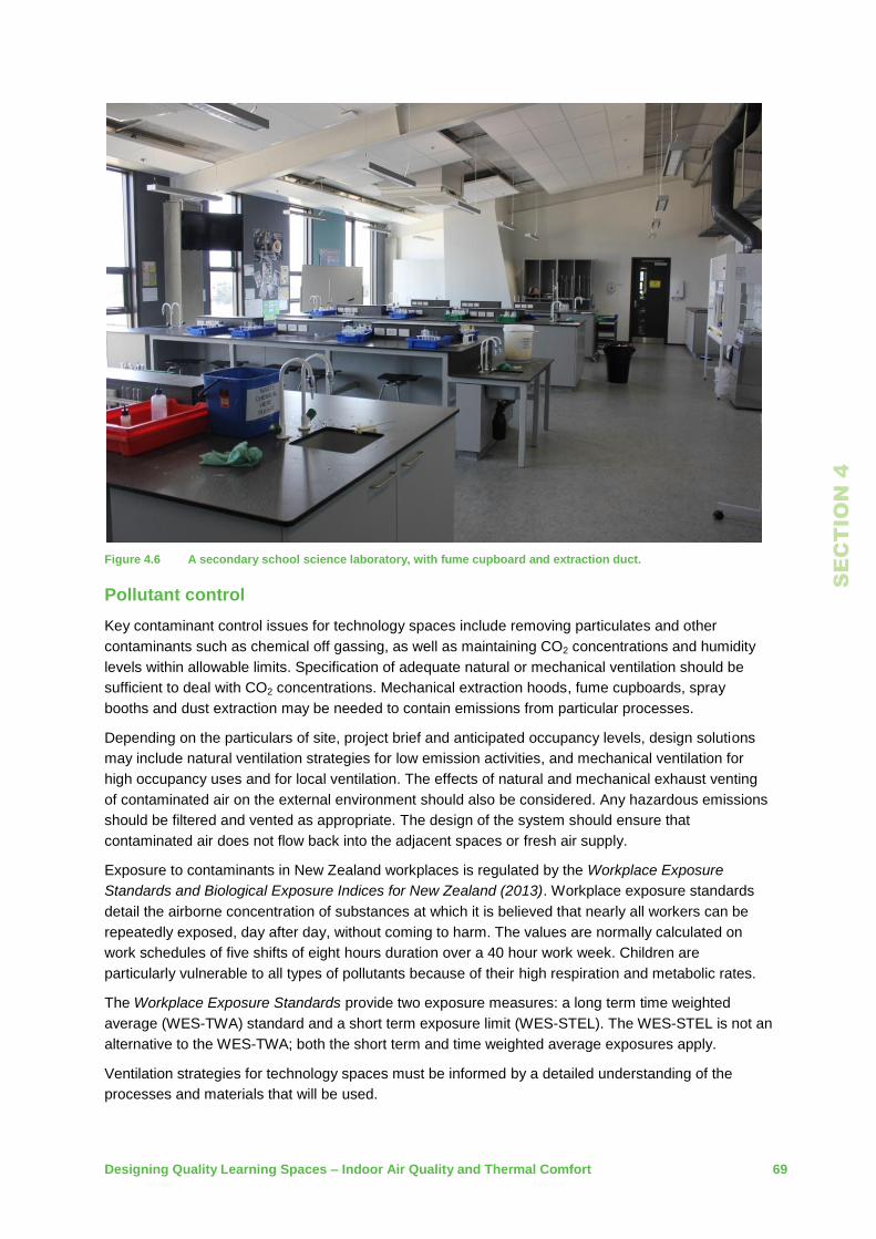
Designing Quality Learning Spaces – Indoor Air Quality and Thermal Comfort 69
SE
CT
IO
N 4
Figure 4.6 A secondary school science laboratory, with fume cupboard and extraction duct.
Pollutant control
Key contaminant control issues for technology spaces include removing particulates and other
contaminants such as chemical off gassing, as well as maintaining CO2 concentrations and humidity
levels within allowable limits. Specification of adequate natural or mechanical ventilation should be
sufficient to deal with CO2 concentrations. Mechanical extraction hoods, fume cupboards, spray
booths and dust extraction may be needed to contain emissions from particular processes.
Depending on the particulars of site, project brief and anticipated occupancy levels, design solutions
may include natural ventilation strategies for low emission activities, and mechanical ventilation for
high occupancy uses and for local ventilation. The effects of natural and mechanical exhaust venting
of contaminated air on the external environment should also be considered. Any hazardous emissions
should be filtered and vented as appropriate. The design of the system should ensure that
contaminated air does not flow back into the adjacent spaces or fresh air supply.
Exposure to contaminants in New Zealand workplaces is regulated by the Workplace Exposure
Standards and Biological Exposure Indices for New Zealand (2013). Workplace exposure standards
detail the airborne concentration of substances at which it is believed that nearly all workers can be
repeatedly exposed, day after day, without coming to harm. The values are normally calculated on
work schedules of five shifts of eight hours duration over a 40 hour work week. Children are
particularly vulnerable to all types of pollutants because of their high respiration and metabolic rates.
The Workplace Exposure Standards provide two exposure measures: a long term time weighted
average (WES-TWA) standard and a short term exposure limit (WES-STEL). The WES-STEL is not an
alternative to the WES-TWA; both the short term and time weighted average exposures apply.
Ventilation strategies for technology spaces must be informed by a detailed understanding of the
processes and materials that will be used.

70 Designing Quality Learning Spaces – Indoor Air Quality and Thermal Comfort
SE
CT
IO
N 4
Good general ventilation in conjunction with local technology space ventilation including mechanical
extraction hoods, fume cupboards, spray booths and directional vents may be needed to contain
emissions from particular processes.
The American Conference of Governmental Industrial Hygienists – Industrial Ventilation, Manual of
Recommended Practice provides practical advice on the design of general and local extract ventilation
systems for metal, plastic and woodworking technology spaces. Reference should also be made to
The Code of Practice for School Exempt Laboratories, published under the HSNO Act (1996).
Ventilation design
Full use should be made of the passive ventilation potential of the space. When emissions of particular
contaminants (including dust and other particulates) are not an issue, natural ventilation may be
adequate. Cross ventilation will generally be most effective. Trickle vents maintain a steady flow of
ventilation at all times. Thermally driven passive ventilation systems may be appropriate in some
higher spaces. General passive design opportunities should be exploited wherever cost effective and
should underpin the overall design process for the building.
Where mechanical extraction hoods, fume cupboards, spray booths and dust extraction are needed to
contain emissions from particular processes, the control for these systems should be accessible and
easy to operate for staff and students. Positioning of controls should support responsible use; ideally,
ventilation controls should be available in close proximity to the targeted equipment.
Provision of “make up” air to local ventilation devices needs to be carefully considered to avoid
draughts and to minimise any adverse effects to the local ventilation device. Any provisions need to be
interlocked with the exhaust systems.
4.6 Workshop technology spaces
Workshop spaces are generally to be ventilated as per learning spaces with any additional specific
ventilation requirements followed.
Dust extraction systems
Careful liaison will be required with technology space teaching staff in regard to layout and details of
equipment requiring dust extraction.
A specialist supplier/installer should be used for any technology space dust extraction system.
The following items of woodwork room machinery are to be provided with extraction:
table saws require a typical air flow rate of 1450 cubic metres per hour (m³/hr) and with two
connections to the dust collection chamber below the table saw and a connection to the guard
above the blade without compromising safety
planer/thicknessers require typical air flow rate of 1450 m³/hr and with alternate connections for
top planing and thicknessing
band saws require a typical air flow rate of 1200 m³/hr, with one connection to the dust collection
chamber below the band saw
sanders should have ventilation specifically designed or specificed by the manufacturer.
For safety reasons the following will apply:
under no circumstances are sanders to be connected to a centralised dust extraction system
dust extraction is not to be provided for items of equipment that are not listed above
sweep up points are not to be connected to centralised dust extraction systems
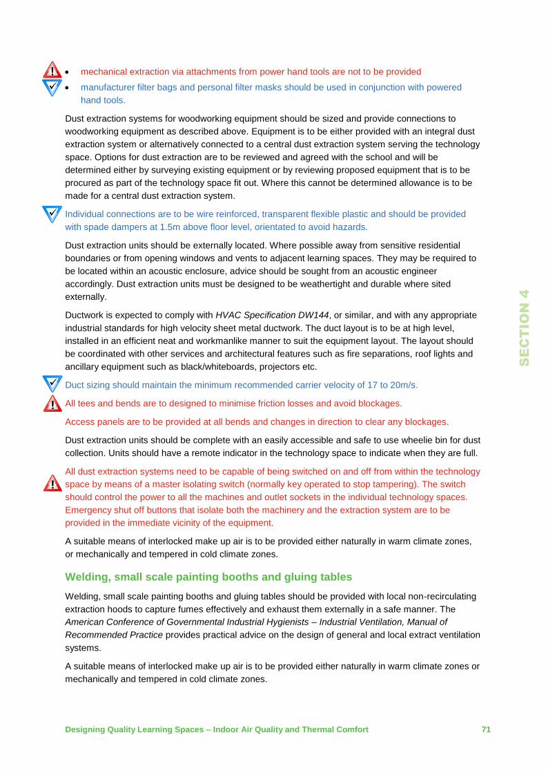
Designing Quality Learning Spaces – Indoor Air Quality and Thermal Comfort 71
SE
CT
IO
N 4
mechanical extraction via attachments from power hand tools are not to be provided
manufacturer filter bags and personal filter masks should be used in conjunction with powered
hand tools.
Dust extraction systems for woodworking equipment should be sized and provide connections to
woodworking equipment as described above. Equipment is to be either provided with an integral dust
extraction system or alternatively connected to a central dust extraction system serving the technology
space. Options for dust extraction are to be reviewed and agreed with the school and will be
determined either by surveying existing equipment or by reviewing proposed equipment that is to be
procured as part of the technology space fit out. Where this cannot be determined allowance is to be
made for a central dust extraction system.
Individual connections are to be wire reinforced, transparent flexible plastic and should be provided
with spade dampers at 1.5m above floor level, orientated to avoid hazards.
Dust extraction units should be externally located. Where possible away from sensitive residential
boundaries or from opening windows and vents to adjacent learning spaces. They may be required to
be located within an acoustic enclosure, advice should be sought from an acoustic engineer
accordingly. Dust extraction units must be designed to be weathertight and durable where sited
externally.
Ductwork is expected to comply with HVAC Specification DW144, or similar, and with any appropriate
industrial standards for high velocity sheet metal ductwork. The duct layout is to be at high level,
installed in an efficient neat and workmanlike manner to suit the equipment layout. The layout should
be coordinated with other services and architectural features such as fire separations, roof lights and
ancillary equipment such as black/whiteboards, projectors etc.
Duct sizing should maintain the minimum recommended carrier velocity of 17 to 20m/s.
All tees and bends are to designed to minimise friction losses and avoid blockages.
Access panels are to be provided at all bends and changes in direction to clear any blockages.
Dust extraction units should be complete with an easily accessible and safe to use wheelie bin for dust
collection. Units should have a remote indicator in the technology space to indicate when they are full.
All dust extraction systems need to be capable of being switched on and off from within the technology
space by means of a master isolating switch (normally key operated to stop tampering). The switch
should control the power to all the machines and outlet sockets in the individual technology spaces.
Emergency shut off buttons that isolate both the machinery and the extraction system are to be
provided in the immediate vicinity of the equipment.
A suitable means of interlocked make up air is to be provided either naturally in warm climate zones,
or mechanically and tempered in cold climate zones.
Welding, small scale painting booths and gluing tables
Welding, small scale painting booths and gluing tables should be provided with local non-recirculating
extraction hoods to capture fumes effectively and exhaust them externally in a safe manner. The
American Conference of Governmental Industrial Hygienists – Industrial Ventilation, Manual of
Recommended Practice provides practical advice on the design of general and local extract ventilation
systems.
A suitable means of interlocked make up air is to be provided either naturally in warm climate zones or
mechanically and tempered in cold climate zones.

72 Designing Quality Learning Spaces – Indoor Air Quality and Thermal Comfort
SE
CT
IO
N 4
Figure 4.7 A secondary school workshop space.
4.7 Science spaces
For science learning spaces reference should be made to all regulatory standards and additionally,
The Code of Practice for School Exempt Laboratories plus the Ministry’s Science Laboratories Design
Guidance document.
Science spaces are generally to be ventilated as a typical learning space.
Fume cupboards
Where a fume cupboard is required, it should be a fixed fume cupboard vented to the outside. A
‘bypass’ design should be used to ensure constant air change regardless of the cupboard’s sash
opening size.
Fume cupboards must comply with the following standards:
AS/NZS 1668.1:2015 The use of ventilation and air conditioning in buildings
AS/NZS 4303:1990 Ventilation for acceptable indoor air quality
AS/NZS 2243.8:2014 Safety in laboratories – fume cupboards.
Mobile recirculating fume cabinets are not recommended, they can only be used in low risk
applications. Ensure a risk assessment is undertaken before opting for mobile cabinets.
If a fixed fume cupboard is required, consider its position within the space and whether the teacher is
going to use the fume cupboard for demonstrations. Consider double sided fume cupboards and
sharing the fume cupboard between the laboratory space and technician room. Consider whether any
other extraction will be required (i.e. for heat or dust).
Ensure adequate make up air for fume cupboards is provided, either naturally in warm climate zones,
or mechanically and tempered in cool and cold climate zones. The location of the make up air supply
should avoid any disruption to the airflow into the fume cupboard.
It should be located to avoid potential disruptions to the air supply to the hood.

Designing Quality Learning Spaces – Indoor Air Quality and Thermal Comfort 73
SE
CT
IO
N 4
Fume cupboard extraction is to be packaged with an inline centrifugal fan that mounts directly on the
duct, eliminating the need for roof platforms.
There should be an ability to quickly flush the laboratory with fresh air.
Chemical storage
Where segregated chemical storage cupboards are provided, these must be vented through chemical
resistant duct systems and comply with the Hazardous Substances and New Organisims Act 1996
(HSNO) or Health and Safety at Work (Hazardous Substances) Regulations 2016.
Food technology and cafeteria kitchen spaces
Depending on the scale and size of the food technology space and its location/climate zone, it is to be
provided with either a natural or mechanical general ventilation system as well as local kitchen extract
ventilation systems.
Where residential hobs/ovens (<8kW) are provided for teaching purposes, each unit is to be provided
with a residential stainless steel kitchen hood sized to match the hob. Alternatively, a commercial
quality hood(s) could be provided to serve a group or line of residential hobs/ovens. In the latter case,
the hood is to be designed and sized in accordance with AS 1668: Part 2-2012.
Commercial kitchen equipment (>8kW), including dishwashers, are to be provided with commercial
kitchen extract hoods designed in accordance with AS 1668: Part 2-2012. There is a preference for
modern hoods with integral make-up air and capture jet designs. UV filtered hoods are to be avoided
for capital and operating cost reasons.
Operation of any gas supply in conjunction with commercial kitchen equipment and associated hood is
to be interlocked such that the gas supply is only available when the hood and any associated make-
up air system is operational.
An automatic gas detection system and shut off system is to be provided.
Venting of extraction points above the roof are to comply with the relevant residential custom and
practice or with AS 1668: Part 2-2012 for commercial exhaust systems, depending on the size of the
cooking facilities. Upstands and back-flashing in accordance with the Ministry’s weathertightness
recommendations will require careful detailing and review.
A suitable means of interlocked “make up” air is to be provided, either naturally in warm climate zones
where appropriate to smaller spaces, or mechanically and tempered in cold climate zones and larger,
more intensively used spaces.
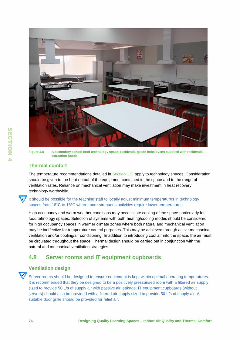
74 Designing Quality Learning Spaces – Indoor Air Quality and Thermal Comfort
SE
CT
IO
N 4
Figure 4.8 A secondary school food technology space: residential grade hobs/ovens supplied with residential
extraction hoods.
Thermal comfort
The temperature recommendations detailed in Section 1.3, apply to technology spaces. Consideration
should be given to the heat output of the equipment contained in the space and to the range of
ventilation rates. Reliance on mechanical ventilation may make investment in heat recovery
technology worthwhile.
It should be possible for the teaching staff to locally adjust minimum temperatures in technology
spaces from 18°C to 16°C where more strenuous activities require lower temperatures.
High occupancy and warm weather conditions may necessitate cooling of the space particularly for
food tehnology spaces. Selection of systems with both heating/cooling modes should be considered
for high occupancy spaces in warmer climate zones where both natural and mechanical ventilation
may be ineffective for temperature control purposes. This may be achieved through active mechanical
ventilation and/or cooling/air conditioning. In addition to introducing cool air into the space, the air must
be circulated throughout the space. Thermal design should be carried out in conjunction with the
natural and mechanical ventilation strategies.
4.8 Server rooms and IT equipment cupboards
Ventilation design
Server rooms should be designed to ensure equipment is kept within optimal operating temperatures.
It is recommended that they be designed to be a positively pressurised room with a filtered air supply
sized to provide 50 L/s of supply air with passive air leakage. IT equipment cupboards (without
servers) should also be provided with a filtered air supply sized to provide 50 L/s of supply air. A
suitable door grille should be provided for relief air.

Designing Quality Learning Spaces – Indoor Air Quality and Thermal Comfort 75
SE
CT
IO
N 4
Thermal comfort
Server rooms should be air conditioned using a dedicated split air conditioning unit. The set point of
the air conditioning unit should be set to comply with the equipment manufacturers recommendations.
If no temperature is specified then 25°C is recommended to minimise energy use. If a Building
Managament System (BMS) is provided, overheating of the server room shall be monitored by an
independent temperature monitoring function of the BMS. If there is no BMS, a high limit direct acting
thermostat set at 30°C is recommended. This should operate an audible alarm immediately outside
the server room. Consideration should be given on larger and more intensive school server rooms for
duplicate split systems.
4.9 Toilets
Ventilation provisions are required to meet the performance requirements of the New Zealand Building
Code. Refer also to the Ministry’s Toilet Reference Design Guide which contains specific requirements
for toilets.

76 Designing Quality Learning Spaces – Indoor Air Quality and Thermal Comfort
SE
CT
IO
N 5
5 Components, Systems and Strategies
This section provides more detailed information on the heating and ventilation performance of
particular components, systems and design elements.
5.1 Thermal performance of construction materials
Building envelope components may have a wide range of R-values, varying from 0.15 m2 K/W (single
glazed windows) to 5 m2 K/W (a well insulated roof/ceiling). The R-value of the thermal envelope as a
whole is a function of the values of its constituent components, as well as their assembly and
installation. Achieving high construction R-values in practice requires both high R-value components
and careful installation to avoid thermal bridging.
The thermal performance of common New Zealand building materials and the calculation of
construction buildup R-values can be found in NZ 4214:2006 Methods of determining the total thermal
resistance of parts of buildings.
Glazing thermal performance
The thermal performance of the glazing types commonly used in New Zealand schools can be found
in NZ4218: 2004/9 Energy efficiency – small building envelope.
5.2 VOC content and formaldehyde
Building components and materials must be specified to fall below the maximum allowable VOC
content, or the maximum allowable VOC emission rates, as prescribed by a NZGBC-recognised eco-
label or indoor air quality scheme.
Refer also to Section 2.8 for the Ministry’s requirements on pollutant control.
Selection of lower VOC and formaldehyde finishes and fittings can be done with very little cost for a
significant advantage in terms of indoor air quality. Key materials with significant areas and effects
include:
carpets
ceiling tiles
paint
adhesives and sealants
furnishings.
Table 5.1 and Table 5.2, below, detail selected New Zealand Green Building Council recognised low
VOC indoor air quality schemes and eco-labels. Specification of materials and components certified
under one of these schemes or labels will help to ensure a less contaminated indoor environment.

Designing Quality Learning Spaces – Indoor Air Quality and Thermal Comfort 77
SE
CT
IO
N 5
Table 5.1 NZGBC-recognised VOC-compliance Indoor Air Quality Schemes (table derived from NZGBC’s
‘Recognised Eco-labels and Indoor Air Quality Schemes’)
Table 5.2 NZGBC-recognised VOC-compliance Eco-Labels (table derived from NZGBC’s ‘Recognised Eco-labels
and Indoor Air Quality Schemes’)
5.3 Window ventilation effectiveness
The choice of window design is important and should provide a range of opening opportunities to allow
occupants to maintain appropriate ventilation for a range of external weather conditions. CIBSE
Applications Manual AM10:2005 also provides more definitive information on the derivation of effective
area, discharge coefficients for natural ventilation openings and the supporting calculations for natural
ventilation design.
Ventilation design principles are discussed in Section 2.9, with the pros and cons of different building
forms and ventilation strategies summarised in Figure 2.8.
5.4 Proprietary ventilation devices
The following proprietary ventilation devices can be used in conjunction with normal opening windows
to enhance a natural ventilation strategy, these include manual or motorised mechanically opened
windows, wind catchers, mixed mode stacks, rotary wind ventilators and ceiling fans.
Eco-Labels AppliedCoatings Flooring Furniture InternalWalls&Partitions
EnvironmentalChoiceNZ-LevelA EC-07-15-Paints
EC-04-11-Wool&wool-rich
pilecarpet
EC-28-15-FloorCoverings
EC-33-14-SyntheticCarpets
EC-32-14-Furniture&Fittings
EC-19-15-Gypsum
Plasterboard
EC-46-15-InteriorLining
Products
GreenTagGreenRate
GreenRatev3.2LevelA
GreenRatev3.2LevelB
GreenRatev3.2LevelC
GreenRatev3.2LevelA
GreenRatev3.2LevelB
GreenRatev3.2LevelA
GreenRatev3.2LevelB
GreenRatev3.2LevelA
GreenRatev3.2LevelB
GreenRatev3.2LevelC
GoodEnvironmentalChoice
AustraliaGECA
GECAPCv2.2i-2012-Paints&
Coatings
GECA50-2011v2-'Carpets'
GECA25-2011v2-'Floor
Coverings'
GECA28-2010v2.1-
'Furniture,Fittings&Foam'
LevelA
GECA28-2006Modified2010
GECA04-2011v2-'Panel
Boards'
InstituteforMarket
TransformationtoSustainability
(MTS)SustainableMaterialsRating
Technology(SMaRT)-LevelA
SMaRT4.0SustainableGold&
Platinum
AustralasianFurnishingResearch
andDevelopmentInstituteAFRDI
GreenTick
AFRDIGreenTickLevel
A/Platinum
AFRDIGreenTickLevelB/Gold
AFRDIGreenTickLevel
C/Silver
CarpetInstituteofAustralia,
EnvironmentalCertificationScheme(ECS)
ECSv1.2Level4(twooptions)
ECSv1.2Level3
ECSv1.2Level2

78 Designing Quality Learning Spaces – Indoor Air Quality and Thermal Comfort
SE
CT
IO
N 5
Manual shaft and lever operable windows
Manual shaft and lever window operators allow windows above normal reach to be easily opened
manually. They can either operate a single sash or group of sash windows. They consist of a manual
gear operated winder at a convenient height to the side of the window, a riser rod and an associated
lever arm at high level attached to the window or group of windows. The windows are also provided
with non-friction stays.
Figure 5.1 Manual window winding gear.
Motorised operable windows
Motorised windows are generally located at high level at the building perimeter and in high level
clerestory or atrium/glazed circulation space windows. At the building perimeter and in clerestories
they provide an alternative to manual shaft and lever operation. They are not to be specified in
locations where their use can trap hands or cause injury.
Motorised windows generally come in three principal types of designs: chain drives, linear push-pull
piston, and rack and pinion. Chain drives are the most common and consist of either one or two
chains per window depending on the size of window. They generally serve high level inward opening
hopper windows, or outward opening casement type windows. Rack and pinion motors are more
suited to roof lights with relatively light frames. Linear push/pull piston motors are suited to both gangs
of roof lights and high level windows.

Designing Quality Learning Spaces – Indoor Air Quality and Thermal Comfort 79
SE
CT
IO
N 5
Figure 5.2 Chain drive window activator.
Figure 5.3 Rack and pinion window activator.
Drives can either be two position (fully open/fully closed), or fully modulating where intermediate
settings can be selected. Modulating motors provide much better control, particularly as the most
controllable range of an opening window is from 0 to 50mm open.
Motorised windows can either be manually operated by switch or push button, or linked directly to a
control system with automatic temperature and/or CO2 control. Experience has shown that the
automatic operation of motorised windows can be problematic due to noise and distraction when
windows are opening and closing continuously. Automation should be limited to rain and high wind
override only. Most window control system suppliers offer proprietary control systems. Alternatively,
they can be BMS controlled.
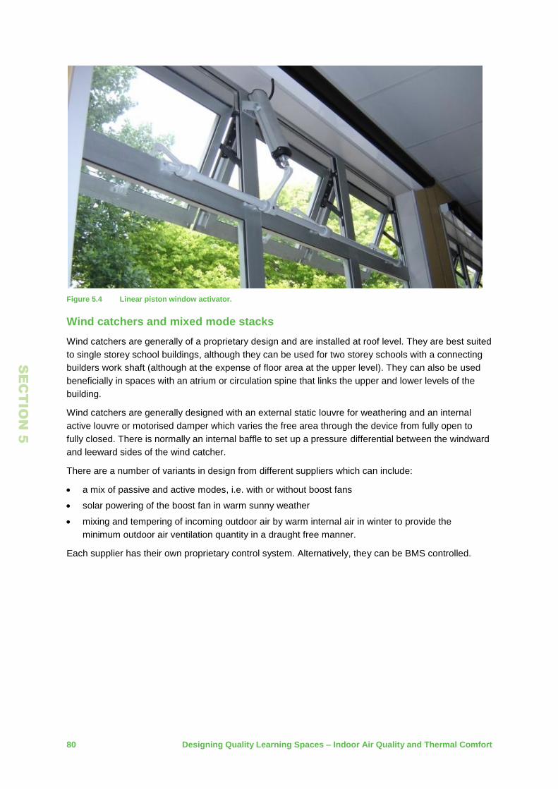
80 Designing Quality Learning Spaces – Indoor Air Quality and Thermal Comfort
SE
CT
IO
N 5
Figure 5.4 Linear piston window activator.
Wind catchers and mixed mode stacks
Wind catchers are generally of a proprietary design and are installed at roof level. They are best suited
to single storey school buildings, although they can be used for two storey schools with a connecting
builders work shaft (although at the expense of floor area at the upper level). They can also be used
beneficially in spaces with an atrium or circulation spine that links the upper and lower levels of the
building.
Wind catchers are generally designed with an external static louvre for weathering and an internal
active louvre or motorised damper which varies the free area through the device from fully open to
fully closed. There is normally an internal baffle to set up a pressure differential between the windward
and leeward sides of the wind catcher.
There are a number of variants in design from different suppliers which can include:
a mix of passive and active modes, i.e. with or without boost fans
solar powering of the boost fan in warm sunny weather
mixing and tempering of incoming outdoor air by warm internal air in winter to provide the
minimum outdoor air ventilation quantity in a draught free manner.
Each supplier has their own proprietary control system. Alternatively, they can be BMS controlled.

Designing Quality Learning Spaces – Indoor Air Quality and Thermal Comfort 81
SE
CT
IO
N 5
Figure 5.5 Typical wind catcher.
Figure 5.6 Typical mixed mode stack with mixing capability for winter outdoor air tempering.

82 Designing Quality Learning Spaces – Indoor Air Quality and Thermal Comfort
SE
CT
IO
N 5
Rotary wind ventilators
A rotary wind ventilator is a passive ventilation device which is driven primarily by the motive force of
the wind, but also by thermal updraughts in relatively still weather. They can move large volumes of air
with no energy expenditure when used with low level air inlets, and are relatively quiet compared to
moving a similar volume of air using a mechanical extract fan.
They can be provided with a motorised damper to stop airflow when required. Care needs to be taken
in the selection of the device with regards to its weathertightness.
Figure 5.7 Roof mounted rotary wind ventilators.
Ceiling fans
Ceiling fans can be helpful during periods of hot weather by increasing air movement and evaporative
cooling. If used effectively they can reduce the apparent sensation of the comfort temperature by up to
2°C.
Care needs to be taken in the selection of ceiling fans in terms of aerodynamic performance and its
potential byproducts; noise and draught.
Unfortunately, cheaper models of ceiling fans are often not suitable due to the fans being unbalanced
and of poor aerodynamic design. These models should be avoided.
Ceiling fan placement in relation to light fittings needs to be carefully considered to avoid stroboscopic
effects.
Ceiling fans should be provided with variable speed rather than stepped speed control.
Ceiling fans should be mounted at least 2.7m from the finished floor level and 200 to 300mm below
the ceiling or in accordance with manufacturers design.

Designing Quality Learning Spaces – Indoor Air Quality and Thermal Comfort 83
SE
CT
IO
N 5
Figure 5.8 Ceiling fan in a typical classroom setting.
Trickle ventilation
Trickle vents are small purpose designed and engineered proprietary openings incorporated into a
window or other building envelope component to provide a background level of outdoor passive
ventilation to spaces intended to be naturally ventilated when windows and doors, etc are otherwise
closed. They can be used to mitigate instances of high CO2 concentrations in naturally ventilated
buildings in winter without recourse to mechanical ventilation.
The effect of trickle vents is to lower both the peak and average levels of CO2 experienced during a
school day. They can be used to ensure compliance with the Ministry’s indoor air quality requirements
in winter months, within naturally ventilated learning spaces.
They typically provide a background level of outdoor air ventilation of 3 to 5 L/s in learning spaces
where adequately provided. Care needs to be taken in their selection and application to avoid
excessive draughts and heat loss in winter. Heating systems must also be sized to withstand
ventilation of cold outdoor air in winter. For this reason they are more suited to warmer climate
regions.
They are designed to be an integral weathertight component of glazing and door framing, as such are
normally provided by the window and door joinery supplier.
More advanced designs incorporate calibrated thermal spring actuators so that they only open at a
specified temperature, as well as acoustic inserts to improve their acoustic properties in noise
sensitive areas.

84 Designing Quality Learning Spaces – Indoor Air Quality and Thermal Comfort
SE
CT
IO
N 5
Table 5.3 Heating/ cooling selection chart. See table for climate zones.
Type Heating or cooling
Climate zone
Heat transfer mechanism and comfort
Heat conversion efficiency ηH (%)
Utilisation system efficiency ηU (%)
Seasonal system efficiency ηS (%)
Economic system life
Floor area warmed
Example
Central or decentralised hot water boiler with low temperature radiators, underfloor heating or warm air fan coils
Heating only Zones 1 to 2
Convection for radiators. Radiant for underfloor heating. Forced convection for fan coils.
Good comfort in winter
Non-condensing gas and wood chip/pellet 85%;
Gas condensing 95%
95%
Non-condensing gas and wood chip/pellet 81%;
Gas condensing 90%
25 – 30 years
Determined by reticulation and boiler size; suitable for whole school with multiple spaces and large areas
Natural gas or wood chip/pellet fuelled hydronic heating system, centrally fed to all school buildings. Coal, LPG and diesel fossil fuels are to be avoided
Central or decentralised air/ground source heat pump with underfloor heating or changeover fan coils
Heating only for underfloor heating. Heating/cooling for fan coils
All zones
Radiant for underfloor heating, Forced convection for fan coils. Good comfort in winter. Changeover fan coils provide option to cool in summer
350% (Heating)
280% (Cooling) 95%
333% (Heating) 266% (Cooling)
25 – 30 years
Determined by reticulation and heat pump size; suitable for multiple spaces and large areas
Central heat pump - hydronic central heating (and potentially cooling if fan coils used), centrally fed to all school buildings or to individual buildings as required. Ground source generally only considered for Zone 3 locations
Electric radiant heaters
Heating only Zones 1 to 2
Radiant. Uneven heating. Can be uncomfortable to sit under
100% 93% 93% 15 years 10-20m2 per panel
Below ceiling-mounted for high temperature electric; integral with ceiling for low temperature
Split or multi split heat pumps
Heating/cooling
All zones
Forced convection. Can be noisy and draughty. Can be used for cooling in summer
400% (Heating)
300% (Cooling) 95%
380% (Heating) 285% (Cooling)
10 years 30-65m2 per unit
Multiple heat pumps per open plan learning space, or individual heat pumps per small room
Packaged ducted air conditioning units
Heating/cooling
Zones 1 to 2
Forced convection. Individual zone control may be a compromise. Can be used for cooling in summer
350% (Heating)
280% (Cooling) 90%
315% (Heating) 252% (Cooling)
15 years
Determined by reticulation and packaged unit size; suitable for multiple spaces and large areas
Packaged units with ducted air distribution zoned according to orientation typically with 3 zones, two perimeter and one central

Designing Quality Learning Spaces – Indoor Air Quality and Thermal Comfort 85
SE
CT
IO
N 5
Figure 5.9 Trickle vents above windows.
5.5 Active heating/cooling systems
Selection of an appropriate heating (and potentially also a cooling system) is a key design decision for
both new schools and for those requiring a significant upgrade and should be subject to a lifecycle
cost analysis as described in Section 5.7. The relative performance of various active heating/cooling
systems is summarised in Table 5.3.
Hydrofluorocarbon refrigerants
The use of hydrofluorocarbon (HFC) refrigerants that are commonly present in commercial heat pump
units will be phased down from 2019 in developed countries such as New Zealand following the Kigali
Amendment to the Montreal Protocol. The agreement requires a 10% reduction in use by 2019 and an
85% reduction by 2036 for developed countries, including New Zealand. The continued availability of
HFC refrigerants and their short to medium term replacement needs to be considered in the selection
of heat pump systems.

86 Designing Quality Learning Spaces – Indoor Air Quality and Thermal Comfort
SE
CT
IO
N 5
Table 5.4 Heating/cooling system comfort assessment.
Type Sub-type Summer comfort
Winter comfort
Central or decentralised hot water boiler with low temperature radiators, underfloor heating or warm air fan coils
Radiators (Note 1) - * *
Underfloor heating (Note 2) - * * *
Fan coils (Note 4) - *
Central or decentralised air/ground source heat pump with underfloor heating or changeover fan coils
Underfloor heating (Note 2) - * * *
Fan coils (Note 4) * * *
Electric radiant heaters (Note 3) - *
Split or multi split heat pumps Split * * *
Multi split (Note 4) * * *
Packaged ducted air conditioning units (Note 4) * * * *
Table 5.4 key: - not applicable * good * * better * * * best
Note 1: Assumes a maximum surface temperature of 50˚C to prevent scalding.
Note 2: The comfort provided by an underfloor heating system is dependent on the following factors:
a maximum floor surface temperature of 25˚C to 26˚C
sufficient mitigation of the effects of solar gain and potential overheating due to slow
response
underfloor heating coils located in a topping slab with insulation directly beneath the
topping slab to minimise the response time to load changes.
Note 3: Assumes the total irradiance at floor level due to the heaters is reasonably uniform and
should not exceed 80 W/m2. The summed spherical irradiance 1.8m above the floor should
not exceed 240 W/m2 and the maximum irradiance from any one heater should not exceed
32 W/m2 at floor level to mitigate asymmetrical radiation and discomfort.
Note 4: Assumes maximum velocity in the occupied zone is less than 0.5m/s in summer and 0.25m/s
in winter.

Designing Quality Learning Spaces – Indoor Air Quality and Thermal Comfort 87
SE
CT
IO
N 5
Figure 5.10 Under floor heating pipework being installed in a school.
Central or decentralised boiler heating systems
Hydronic central heating uses a central boiler unit to heat water which is then piped through a
reticulation network to convective radiators, underfloor heating coils or warm air fan coils in each of the
spaces that require heating.
Traditionally, school boiler systems used cheap coal as a fuel source. However, the use of coal is now
discouraged due to resource consent requirements and its high greenhouse gas emissions.
Advantages of central boiler systems include the ability to use low cost fuels such as natural gas and
wood chip. The life spans of the central boiler and hydronic distribution system should be between 25
to 30 years, so they last a long time if well maintained. Smaller condensing boilers will have a shorter
lifespan.
Disadvantages of central boiler systems include relatively low efficiency compared to heat pumps.
This includes both the seasonal efficiencies of the boiler plant and the utilisation efficiency of the
heating system, which together contribute towards the overall system efficiency.
The response time of a central system is slow due to the time required to heat and circulate the
heating water. This can be reduced by decentralising the heat source so that smaller boilers serve
individual buildings or groups of buildings. This also reduces distribution losses, but adds to capital
and maintenance costs. System efficiencies are typically reasonably high and can be improved by
using condensing boilers if natural gas is used as a fuel. Efficiency can also be improved by
minimising circulating lengths of pipework and through effective insulation of the reticulation network.
88 Designing Quality Learning Spaces – Indoor Air Quality and Thermal Comfort
SE
CT
IO
N 5
By and large, central boiler systems need to start earlier than more instantaneous systems such as
split/multi-split and electric radiant panels. The installation, testing, commissioning and maintenance of
boiler installations are to comply with the WorkSafe NZ approved code of practice for boilers.
Boiler options
Boilers can be fuelled with a variety of fuels, including natural gas and biomass such as wood chip or
wood pellet. Carbon emissions from fossil fuel use are an important issue and high greenhouse
emission fuels such as coal, LPG and fuel oil boilers should be avoided.
Where natural gas is available, larger centralised boilers are generally non-condensing and operate
with higher flow temperatures (70°C to 80°C) and have reasonably high seasonal efficiencies of
around 80%. Non-condensing natural gas boilers are very reliable and have a long operating life.
Using natural gas in conjunction with smaller and more domestically suited condensing boilers
enables lower water flow temperatures (40°C to 45°C) to be used by decentralised boiler systems.
This arrangement offers higher seasonal efficiencies of around 90%, particularly at low return water
temperatures.
Wood chip boiler installations are relatively complex as they require automated fuel delivery and ash
removal systems, as well as a significant fuel storage area to minimise transport costs. Sizing of the
wood chip boiler installation is critical, it is important not to oversize it. The use of an accumulator or
thermal storage vessel is also helpful in this respect. The complexity of the installation adds to its
capital cost.
As an alternative to wood chip, wood pellets are a manufactured wood fuel product made from waste
material such as untreated sawdust and shavings. The cost of pellets is significantly affected by
transport, as the supply of pellets is more limited geographically than wood chip. The main advantages
are their higher energy density, clean burning and the correspondingly lower storage capacity
required. They tend to be used for smaller boiler loads.
The choice between wood chip and wood pellet is dependent on factors such as location, energy
requirements, existing/modified wood burning technology, site issues such as fuel storage capacity
and access for delivery vehicles.
Heat emitter options
Low temperature radiators (convectors) are heat emitters which include low surface temperature
fascia panels. The fascia panel is designed to not reach temperatures which will burn the skin (>50°C).
While the Building Code limits the temperature of hot water accessible to students at the tap to be less
than 45°C, solid surfaces can be slightly hotter.
Underfloor heating can provide a very comfortable environment. The thermal inertia of underfloor
heating systems means that they respond slowly on initial start up and to load changes. The heating
coils should be placed in a topping slab to improve the response time. Large expanses of unshaded
glazing should be avoided, as the slow response of the underfloor heating may lead to overheating
issues.
Convective heating by fan coils at high level is generally the least comfortable heating solution and
can be prone to draughts and stratification. However, it can be used in cold climates to mix
recirculated and outdoor air for ventilation in winter.

Designing Quality Learning Spaces – Indoor Air Quality and Thermal Comfort 89
SE
CT
IO
N 5
Figure 5.11 Boiler options.

90 Designing Quality Learning Spaces – Indoor Air Quality and Thermal Comfort
SE
CT
IO
N 5
Figure 5.12 Decentralised gas boiler replacement project.
Figure 5.13 A centralised school woodchip boiler installation.

Designing Quality Learning Spaces – Indoor Air Quality and Thermal Comfort 91
SE
CT
IO
N 5
Central or decentralised hydronic air, ground, or water source heat pump systems
Hydronic heat pump systems use a central or decentralised air or ground source heat pump rather
than a boiler. A boiler heats or cools water which is piped through a reticulation network to either
underfloor heating, low surface temperature radiators (convectors), or fan coils in each of the spaces
that require heating. The fan coils allow both heating/cooling via reversible/changeover operation. The
limited cooling function of underfloor coils in conjunction with floor coverings and the potential for
condensation, generally preclude a boiler for cooling functions.
Air and ground source hydronic heat pumps
Hydronic heat pumps are mechanical units capable of harnessing temperature differentials from an
external ambient air or ground source, utilising an outdoor air coil or ground loop captor. The energy is
supplied to a hydronic circuit using a compressor to transfer heat energy efficiently between the two.
The efficiency of a heat pump is frequently quoted as a coefficient of performance (COP) rating.
In colder climates a ground source heat pump has some advantages in terms of COP and defrost
requirements, although at a reasonable cost premium. The significant ground works for either vertical
or horizontal captors make ground source heat pumps significantly more expensive in terms of capital
cost.
Hydronic heat pump central systems are more energy efficient than conventional central boiler
systems due to their use of ambient temperature differentials as an energy source. They do require
electrical power, but are typically three to four times more energy efficient than conventional boilers at
maximum load.
Disadvantages include relatively high capital costs and compressor life spans limited to around 15 to
20 years. The hydronic distribution system should last longer at 25 to 30 years.
The systems can be decentralised in a similar manner to that described for boilers. System
efficiencies can be reasonably high, and can also be improved through effective insulation of the
primary reticulation network. Central hydronic heat pump systems generaly need to start earlier than
more instantaneous or decentralised systems such as split/multi-split and electric radiant panels.
Ensure heat pump selection considers the implications of HFC refridgerants being phased out in the
future under the Kigali Amendment. This is discussed more under the heading hydrofluorocarbon
refrigerants.
Heat emitters/cooling emitters
Underfloor heating can be used in a similar way to boilers, ideally suited to the lower output
temperatures possible from heat pumps.
Radiators and convectors can also be used, although their sizing will be considerably larger than for
those served by boilers. Low surface temperature panels are not required.
Fan coils can be used in a changeover arrangement with reversible heat pumps providing heating in
winter and cooling in summer. Care needs to be taken in the specification of piping and insulation to
avoid condensation and sweating in the cooling mode.

92 Designing Quality Learning Spaces – Indoor Air Quality and Thermal Comfort
Figure 5.14 Heat pump heating/cooling options.

Designing Quality Learning Spaces – Indoor Air Quality and Thermal Comfort 93
SE
CT
IO
N 5
Single split and multi-split air source heat pumps
Air source heat pumps may be configured in two ways, as a single split or multi-split variant refrigerant
flow (VRF) system.
Single split heat pumps are mechanical units capable of harnessing temperature differentials from an
external air source (outdoor unit) to an interior source (indoor unit), using an inverter compressor to
efficiently transfer heat energy efficiently between the two. Split heat pumps can be used either to heat
or to cool a space, and to moderate temperature extremes during both winter and summer. They are
more energy efficient than conventional electrical resistance heaters, due to their use of existing
temperature differentials as an energy source. They require electrical power, but are typically 3 to 4
times more energy efficient than conventional electric radiant and panel heaters. The efficiency of a
heat pump is frequently quoted as a COP rating.
Single split heat pumps are among the most capital cost efficient methods of providing conditioned air.
The short life span of heat pumps (typically around ten years) is an issue that needs to be considered
in any lifecycle cost analysis. The outdoor unit needs to be protected from corrosion, particularly in
geothermal or salt spray zones (within 15km of the coast).
Factors to consider when selecting a heat pump include:
a demand defrost control, which performs defrost cycling only when needed, rather than on a
regular cycle, in cold climate zones
centralised control with local override capability, so that heat pumps may be centrally managed
while allowing a degree of local climate control by occupants.
Multi-split heat pumps operate in a similar manner to split systems, except that one external unit
serves multiple indoor units. Their main advantages are that the location of one large central unit,
rather than multiple outdoor units, can be easier to handle visually and from a maintenance, security
and accessibility point of view. Split heat pumps also tend to be of a residential nature, whereas multi-
splits tend to be of a commercial nature and should last longer (approximately 15 years).
The designer should consider noise attenuation through acoustic separation around the equipment or
locating the external unit an appropriate distance away from school buildings. Refer to the DQLS –
Acoustics guidelines for Ministry requirements.
Where large systems are used to serve small rooms, care needs to be taken to ensure adequate
refrigerant leakage detection and ventilation. Hybrid refrigerant/water systems can be used to reduce
the size of refrigerant charge. Hybrid systems may also become more prevalent due to the Kigali
Amendment’s proposed phase out of HFC refrigerants. This is discussed more under the heading
hydrofluorocarbon refrigerants.
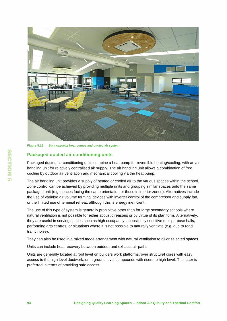
94 Designing Quality Learning Spaces – Indoor Air Quality and Thermal Comfort
SE
CT
IO
N 5
Figure 5.15 Split cassette heat pumps and ducted air system.
Packaged ducted air conditioning units
Packaged ducted air conditioning units combine a heat pump for reversible heating/cooling, with an air
handling unit for relatively centralised air supply. The air handling unit allows a combination of free
cooling by outdoor air ventilation and mechanical cooling via the heat pump.
The air handling unit provides a supply of heated or cooled air to the various spaces within the school.
Zone control can be achieved by providing multiple units and grouping similar spaces onto the same
packaged unit (e.g. spaces facing the same orientation or those in interior zones). Alternatives include
the use of variable air volume terminal devices with inverter control of the compressor and supply fan,
or the limited use of terminal reheat, although this is energy inefficient.
The use of this type of system is generally prohibitive other than for large secondary schools where
natural ventilation is not possible for either acoustic reasons or by virtue of its plan form. Alternatively,
they are useful in serving spaces such as high occupancy, acoustically sensitive multipurpose halls,
performing arts centres, or situations where it is not possible to naturally ventilate (e.g. due to road
traffic noise).
They can also be used in a mixed mode arrangement with natural ventilation to all or selected spaces.
Units can include heat recovery between outdoor and exhaust air paths.
Units are generally located at roof level on builders work platforms, over structural cores with easy
access to the high level ductwork, or in ground level compounds with risers to high level. The latter is
preferred in terms of providing safe access.

Designing Quality Learning Spaces – Indoor Air Quality and Thermal Comfort 95
SE
CT
IO
N 5
Their main advantage is in their selective use for specific applications and their ability to combine
ventilation and heating/cooling functions such that indoor air quality and thermal comfort requirements
can be largely guaranteed. The main disadvantage is the high capital, energy and maintenance costs
of the fans for mechanical ventilation and the compressors/outdoor fans. Other maintenance costs
include filter changes and component replacement, particularly the compressors and outdoor coil fans.
Figure 5.16 Reverse cycle heat recovery packaged units installed on the roof of a school.
Figure 5.17 Multiple reverse cycle heat recovery packaged units installed on the roof of a school.
Ensure heat pump selection considers the implications of HFC refridgerants being phased out in the
future under the Kigali Amendment. This is discussed more under the heading hydrofluorocarbon
refrigerants.

96 Designing Quality Learning Spaces – Indoor Air Quality and Thermal Comfort
SE
CT
IO
N 5
Electric radiant heaters and panel heaters
High temperature electric radiant heaters emit infrared energy which heats surfaces on impact, with
minimal heating of the intervening air. There are also lower intensity electric heating cassettes that fit
into ceiling tiles. These are prmiarily suitable for smaller well insulated rooms with lower heating
requirements, as their output tends to be more convective and hence more prone to stratification.
Radiant heaters can be a cost effective means of providing intermittent heating in learning spaces in
warmer climate zones and in deeper plan learning spaces where the demand for heating through the
building fabric is significantly reduced. They also suit large sporadically heated spaces such as
gymnasiums and halls, which would be expensive to heat by other means.
Radiant heaters must be sized and positioned strictly in accordance with the supplier’s installation
instructions so that they provide an appropriate degree of heating. Improper deployment may cause
over or underheating, discomfort, burns or fire. Radiant heaters should never be positioned in close
proximity to flammable materials, or directed at highly conductive surfaces (such as metal) which may
absorb heat and constitute a burn risk.
Lower intensity electric heating cassettes that are designed to integrate within a standard ceiling tile
grid are not preferred in significant quantities as they can have an impact on the acoustics of the
space.
The main advantage of electric radiant heaters is their low capital cost. However, the cost of direct
electricity compared to gas or heat pumps makes their operating cost expensive. Their life is also
relatively short at around 15 years.
Electric panel (convection) heaters can also be used in intermittently occupied spaces such as
administrative areas. Their use in learning spaces is not recommended as they can be easily blocked
and can have high surface temperatures.
Figure 5.18 High level ceiling-mounted radiant heating panels installed in a gymnasium.

Designing Quality Learning Spaces – Indoor Air Quality and Thermal Comfort 97
SE
CT
IO
N 5
5.6 Building control systems
Modern building controls are invariably of the direct digital control (DDC) type which can be developed
into a building management system with the addition of a graphical user interface (GUI).
Schools have relatively simple systems and requirements, and do not require an overly sophisticated
and potentially underutilised system.
It is important to correctly configure the BMS settings and it is recommended that a continuous
commissioning approach is adopted, whereby the installer is responsible for adjustments in the early
stages of a building’s occupancy.
Basic requirements for the system should include:
being able to time schedule the operation of the school systems easily, with a simple way of
setting holiday modes etc
having after hours controls in each principal space that allows operation of the systems outside
core hours. The controls should not allow potential user error to affect the normal timer settings
zoned temperature control in each principal space. Heating temperature set point 19°C +/- 1°C.
Cooling set point 24°C +/- 1°C. The actual temperatures across the zone may vary from the
sensor location. Avoid sensor locations subject to direct sun or draughts, or on external walls
having internal and external temperature and CO2 sensors in each principal learning space, and
potentially a local GUI informing staff and students on the use of windows and ceiling fans
boiler temperature and safety controls integral to the boiler where provided. Gas boiler
temperature and load control should maintain the boiler’s seasonal efficiency, preferably by a
modulating control burner, or as a minimum by a ‘high-low-off’ control. Wood chip/pellet boilers
should use an accumulator for load control and back end protection
where an HVAC system is required, it can either have proprietary controls for split and multi-split
A/C units, or more developed routines with CO2 control and economiser cycles for packaged
ducted air conditioning systems. High level interfaces with BMS systems are also possible
motorised windows should be controlled by a proprietary direct acting control with manual push
button (0 to 100% continuous) operating range. BMS operation of windows should be limited to a
timed closure at the end of the school day, and high wind/rain override for exposed windows
metering of primary energy inputs; mains electricity, gas, etc. Submetering is to be limited to direct
reading meters in each principal school building, but not linked to the control system
critical plant alarms, e.g. boiler lock out or power failure, and email/text messaging to caretaker.
5.7 Lifecycle cost
Lifecycle cost (LCC) analysis requires consideration of initial economic costs, as well as all likely
subsequent costs and economic inflows. LCC facilitates the economic comparison of options with
different life spans and cost structures. It is thus a useful tool in selecting between different design
options.
LCC analysis applies a discount rate to the future cash flows arising from a design option, and
displays these as a present value which may then be compared directly with the present values of
competing options. New Zealand Treasury’s published Public Sector Discount Rate for infrastructure
and special purpose (single use) buildings should be used in calculating LCCs. This is a real discount
rate, and, general inflation effects do not need to be taken into account.

98 Designing Quality Learning Spaces – Indoor Air Quality and Thermal Comfort
SE
CT
IO
N 5
Capital costs for different building services options should be jointly agreed by the building services
engineer and the quantity surveyor. Capital costs should include all associated costs, e.g. associated
infrastructure costs and any associated builder’s work. Any residual value of the system is to be
accounted for at the end of the term in the present value analysis.
Annual energy costs associated with different building services systems should be approximated by
the use of energy modelling or by other estimation methods. These costs should be energy cost
inflation adjusted where the rate is significantly in excess of the general inflation rate.
Fuel/energy prices are to be assessed using the current costs for the various fuels and energy
sources, based on MBIE energy price information.
The economic costs included in LCC analyses should be as inclusive of capital, operating and
maintenance costs as practicable. Replacement costs should include all costs incurred to support the
efficacy of the option under analysis during its life span.
An approximate allowance for annual maintenance for building services systems is to be 1% of the
capital cost for the first year, rising linearly to 2% at the end of the overall economic system life given
in Table 5.5. This can be used as the basis of the annual maintenance cost in the LCC analysis.
Indicative life expectancy factors for building services system components are given in the CIBSE
Guide Book M – Maintenance Engineering and Management. These can be used for the frequency of
replacement costs in the LCC analysis. Only replacement <20 years need to be considered in addition
to the annual maintenance costs described above.
Table 5.5 details the life expectancies for various components. These life expectancies should be
used in determining component replacement costs as part of a LCC analysis.

Designing Quality Learning Spaces – Indoor Air Quality and Thermal Comfort 99
SE
CT
IO
N 5
Table 5.5 Equipment life expectancies < 20 years for assessment of replacement costs.
Component Life expectancy
Main plant
Gas boilers >20 years
Oil boilers >20 years
Woodchip boilers 15 years for fuel handling system
Condensing gas boilers (modular) 15 years
Air source heat pump 15 years
Ground source heat pump 15 years
Distribution system
Water piping and insulation >20 years
Ductwork, grilles, diffusers and dampers >20 years
Refrigerant piping system and refrigerant replacement 10 - 15 years
Electrical distribution system >20 years
Heating systems
Radiators >20 years
Underfloor heating >20 years
Fan coil units 15 years
Packaged Air Conditioning Systems
Split air conditioners 10 years
VRV air conditioning system 15 years
Packaged air conditioning units 15 years
Controls
Controllers/outstations 10 years
Software 5 years
Valves 15 years
Dampers 15 years
Actuators 10 years
Head end 5 years
Networking >20 years
Costs that should be excluded from LCC analyses include asset depreciation, capital charges/finance
interest rates (these are accounted for in the discount rate), decommissioning costs, general inflation
and GST. For the purposes of the analysis, any decommissioning/demolition costs at the end of life
within the analysis term is to be assumed to equal the scrap value of the system.
LCC analyses only account for economic costs and inflows. Competing options may involve attributes
that cannot be readily reduced to economic values. Qualitative attributes may include health/comfort,
environmental impact (in particular from greenhouse gas emissions) and ease of use considerations/
school disruption.
These non-economic considerations should form part of the overall decision making, along with LCC
analysis, by means of a ranking and weighting type analysis. The weighting of the various system
attributes are to be determined in conjunction with the Ministry. Typically, they might be assumed as
follows:

100 Designing Quality Learning Spaces – Indoor Air Quality and Thermal Comfort
SE
CT
IO
N 5
LCC (25%)
health/comfort (30%)
environmental impact (20%)
ease of use/school disruption (25%).
Further guidance on conducting LCC analyses can be found in the New Zealand Treasury Whole of
Life Costs circular.
LCC report requirements
For all new, upgrade or replacement projects over 300m², or with floor areas greater than three
teaching space equivalents (whichever is the lesser), an options report is to be provided by the
designers at the project’s preliminary or developed design stage.
It should include:
a choice of heating, ventilation and cooling systems appropriate to the microclimate and local site
environment
lifecycle cost analysis for each option with a ranking and weighting analysis
a present value analysis that considers capital, energy, maintenance and replacement costs. The
period of analysis is to be 20 years. The discount rate is to be that currently published by the
New Zealand Treasury for infrastructure and special purpose (single use) buildings. The discount
rate published by the New Zealand Treasury as at October 2016 is 6%.
The options and costs presented are to be free of any perceived bias towards a particular/preferred
design solution. Based on this report and on costings, the Ministry, in conjunction with the designers,
will determine which system(s) are the most appropriate for the particular school project, so that
capital and operating budgets can be forecast.
5.8 Safety in design
Safety in design is a formal and systematic approach/procedure that integrates risk management
techniques into the design process to identify, assess and treat health and safety risks to people over
the lifecycle of an asset, including construction, operation, maintenance and demolition.
Examples of specific indoor air quality and thermal comfort issues are included under the following
headings.
Indoor air quality
CO2 levels are maintained in accordance with the Ministry requirements given in Section 1.1 by the
provision of suitable ventilation (natural, mechanical, or a combination of both).
CO2 levels are monitored and displayed in the learning space and advice is given to staff and students
on how to maintain the required conditions.
Interior finishes (flooring, ceilings and walls, paints, adhesives and sealants etc.) are to be selected
with low VOC emissions as stated in Sections 2.9 and 5.2.
The combination of ventilation, insulation and moisture control will be sufficient to limit the humidity to
less than 65% and to prevent mould growth and interstitial condensation.
Suitable and cleanable entry/exit mats are provided at principal building entry and exit points.

Designing Quality Learning Spaces – Indoor Air Quality and Thermal Comfort 101
SE
CT
IO
N 5
Suitable cleaning regimes using well maintained HEPA filtered vacuum cleaners and
natural/environmentally friendly cleaning products are put in place to reduce particulate levels within
the school on a regular basis.
Ventilation
Ventilation provisions as described in Sections 1.1 and 1.2 are generally above those required by the
New Zealand Building Code Clause G1.
Where natural ventilation openings are provided there are suitable restraining mechanisms to:
prevent falling out of the windows
prevent windows/openings projecting into circulating paths other than at a safe level above the
finished floor level
any motorised openings are not within the reach of staff or students.
Any mechanical ventilation plant can be safely maintained. Siting of plant on roofs requires
appropriate consideration for safe access.
Any mechanical ventilation systems are to comply with AS/NZS 3666.1 and AS/NZS 3666.2 in terms
of microbial control for design, installation, commissioning, operation and maintenance. Filtration
levels are to be appropriate to pollutant levels in the outdoor air.
Laboratory safety is to be in accordance with HSNO requirements and Code of Practice for School
Exempt Laboratories.
Any local ventilation systems and fume cupboards are to be in accordance with Section 4 of this
guideline and any associated standards and regulations.
All requirements of the fire report are reflected in the ventilation system designs.
Temperature control
Temperatures are maintained in accordance with the Ministry’s requirements given in Sections 1.3 by
the provision of suitable heating/cooling (passive or active) to avoid any undue heat or cold stress to
staff or students.
Temperatures are monitored and displayed in the learning space and advice is given to staff and
students on how to maintain the required conditions.
Heating
The design, safe operation, maintenance and servicing of any boiler is in accordance with the
WorkSafe NZ approved code of practice for boilers.
High temperature electric radiant panel heaters are installed strictly in accordance with the
manufacturers’ requirements in terms of mounting heights and separation distances.
The surface temperature of heat emitters which can be touched by students is kept below 50°C.
Cooling
Any cooling equipment is located at ground level in a secure enclosure that cannot be accessed by
students.

102 Designing Quality Learning Spaces – Indoor Air Quality and Thermal Comfort
SE
CT
IO
N 5
General
Prior to any demolition or construction work, any heating, ventilation and air conditioning services and
any associated electricity, water or gas services crossing the site or installed within existing buildings
are to be identified and made safe.
Plant equipment is to be located with due care with appropriate safe access and provision for servicing
and ongoing maintenance. Design teams need to justify the positioning of equipment and how it will be
accessed and maintained safely.
Electrical installations are to comply with AS/NZS 3000.
Gas installations are to comply with AS/NZS 5261 and must include: a manual shut off valve, an
automatic gas shut off valve linked to the fire alarm system, and also a seismic shut off valve. Local
shut off facilities are to be provided in laboratories and kitchens.
Heating, ventilation and air conditioning systems are to be properly tested and commissioned to either
CIBSE or ASHRAE standards, to demonstrate compliance with the New Zealand Building Code, any
relevant standards, and the requirements of this DQLS guideline.
The Ministry is to be provided with suitable operating and maintenance manuals, and construction
record drawings. School management and caretaking staff are to be provided adequate training to
enable the heating, ventilation and air conditioning systems, plant and equipment, to be safely
operated and maintained.
Compliance schedules are to be provided for specified systems as part of the building consent to
identify continued maintenance, testing and warrant of fitness requirements.

Designing Quality Learning Spaces – Indoor Air Quality and Thermal Comfort 103
6 Glossary and References
6.1 Glossary
Active cooling Cooling provided by a mechanical system. Also called air
conditioning.
Air pollutant Any substance (dust particulates, chemical compounds, or other
airborne materials) that may be harmful or irritating to occupants
when present in sufficiently high concentrations.
Allergen A substance (often a protein, such as pollen) that induces an
abnormal immune response in people who are sensitive to it. Even in
minute concentrations, some allergens can cause severe reactions in
sensitive people.
Borrowed air The use of air from one ventilated enclosure to ventilate an adjoining
enclosure.
CFD modelling Computational fluid dynamics (CFD) modelling simulates the
movement of fluids (including air) within a system. It can be used to
model the thermal behaviour and airflow patterns of complex spaces,
including interactions between building elements, occupational
patterns and the effects of changing external conditions.
Conduction Thermal conduction is the transfer of heat energy between (or within)
bodies through the sympathetic excitation of their constituent
particles – typically at the atomic or molecular scale. Conductive heat
transfer between bodies can only occur if the bodies are in direct
physical contact. The thermal conductivity of a material is a function
of its internal atomic or molecular structure. Metals are typically good
conductors due to the fluid nature of their electron-bonding matrix,
which allows free-moving electrons to rapidly transfer energy within
the material.
Convection Thermal convection is the transfer of heat energy through the
movement of a fluid medium (including air). Convection usually
consists both of conductive heat transfer within the fluid and the bulk
movement of the fluid within the containing space (advection, or heat
transfer by bulk fluid flow). Effective convection heating of a space
requires both local heating of the air and effective circulation of the
air throughout the space.
Cross ventilation Ventilation whereby air is introduced into a space on one side by
positive air pressure and then drawn across the space and vented
from the other side by negative air pressure. Natural cross ventilation
utilising wind and local air movements is a common and effective
ventilation strategy, particularly in small, spatially simple enclosures.

104 Designing Quality Learning Spaces – Indoor Air Quality and Thermal Comfort
Flow-through
ventilation
A ventilation strategy whereby air is introduced into one enclosure
and then directed through successive enclosures, before then being
vented to the external atmosphere.
Free cooling A method of providing cooling and air conditioning to buildings and
industrial processes, using natural sources of cold air (or cold water).
Free cooling avoids or reduces the use of conventional energy
sources in the provision of cooling. If external ambient air
temperatures are low enough, the thermal fluid used in the cooling
process (typically air, water, or another fluid) bypasses the
conventional chiller system and instead dissipates heat to the natural
cold source.
Fresh or outdoor air External air as used for ventilation, filtered or otherwise treated
where necessary. Not always fresh, so more accurately referred to
as outdoor air.
Glazing system The glass and framing of windows and doors; these may be specified
to achieve a variety of temperature control, acoustic, lighting and
ventilation outcomes. The glazing system may be an integral part of
a heating, ventilation, acoustic or lighting design strategy.
Heat conversion
efficiency (ηH)
A measure of the efficiency with which a system converts the
potential energy of the input fuel into useful output energy
(heating/cooling output) under standard test conditions. The heat
conversion efficiency of a system is determined by dividing its output
energy by the potential energy of the input fuel. This measure is
based on standard test conditions and does not take into account
inefficiencies arising from actual operating conditions, which are
captured by the system utilisation efficiency (see Utilisation
efficiency, below).
Heat pump A mechanical unit capable of harnessing temperature differentials
(from air or other sources such as the ground) in order to transfer
heat energy between two spaces. Heat pumps use compressors and
phase-change refrigerant fluids to move heat energy counter to the
spontaneous direction of thermal flow. They may be used to either
heat or cool a space. They are more energy efficient than
conventional electrical resistance heaters, due to their use of existing
temperature differentials as an energy source. They do require
electrical power, but are typically 3 to 4 times more energy efficient
than conventional electrical resistance heaters. The efficiency of a
heat pump is frequently quoted as a coefficient of performance
(COP) rating. Disadvantages include relatively high capital costs and
life spans limited to around 15 years.
HVAC A generic term for a system that provides heating, ventilating or air-
conditioning (HVAC) in various combinations.

Designing Quality Learning Spaces – Indoor Air Quality and Thermal Comfort 105
Hydrofluorocarbon
(HFC) refrigerants
HFCs are used as substitutes for CFCs (Chlorofluorocarbons) and
HCFCs (ozone depleting substances) that were phased out under
the 1987 Montreal Protocol. Refrigerants are a major use for HFCs.
The main environmental concern with HFCs is the role these
compounds play as greenhouse gases, influencing climate
change. In 2016, the Kigali Amendment to the Montreal Protocol
agreed on phasing out HFCs, beginning with a 10% reduction by
2019 and an 85% reduction by 2036 for developed countries,
including New Zealand.
Hydronic heating A reticulated heating system whereby water (or another thermal fluid)
is heated by a central boiler unit or hydronic heat pump and piped to
radiator units in the heated spaces. Hydronic systems may also be
configured to provide cooling.
Insulating glazing unit
(IGU)
A single, double or triple glazed unit, together with its framing, the
spacer material that separates the panes and any reflective or tinted
coatings. IGUs are typically designed and specified to improve the
acoustic and thermal insulation performance of the building.
Interstitial
condensation
A form of condensation that occurs when warm moist air penetrates
inside a wall, roof or floor structure, reaches the dew point due to the
construction being cold and condenses into liquid water.
Make up air Air that is introduced into a space to replace air that has been
removed through either passive or mechanical means. In order to
achieve high levels of weathertightness and thermal resistance,
modern buildings tend to be airtight. This means that minimal outside
air is able to infiltrate the building when doors, windows and other
vents are closed. If mechanical ventilation is then used to remove
contaminated air, fresh air will not be able to infiltrate the building,
which will instead depressurise. In the absence of a make-up air
source, natural ventilation systems will also fail. Make up air may be
provided through simple vents, or through pressure-sensitive or
extract-triggered dampers.
Mechanical ventilation Ventilation whereby air is moved through an enclosed space by a
mechanical device such as a fan.
Natural ventilation Ventilation provided by natural means, such as openable windows,
doors or vents. Natural ventilation relies on internal/external air
pressure differentials, or on vertical thermal differentials within
building spaces (the stack effect), to drive air movement. Natural
ventilation stands in contrast to mechanical ventilation, which relies
on motor driven fans to distribute air within a building space.
Passive ventilation
and cooling
See Natural ventilation, above.

106 Designing Quality Learning Spaces – Indoor Air Quality and Thermal Comfort
Plenum space A cavity or space in a building, typically between a dropped ceiling
and the structural ceiling, or under a raised floor, that is used to
house ventilation ducts, communications cabling, or other building
services infrastructure.
Relative humidity (RH) The water vapour concentration present in a sample of air,
expressed as a percentage of the concentration the air could hold if
fully saturated (i.e. at a particular temperature and pressure).
R-value See Thermal resistance below.
Seasonal efficiency
(ηS)
The actual efficiency of a heating/cooling plant deployed in a real-
world setting may depart from that determined under standard test
conditions. This may be due to partial loading, seasonal variations in
ambient temperature, maintenance considerations and system
control protocols. The seasonal efficiency of a unit is defined as its
heating/cooling output during a typical operating season, divided by
the input energy over the same period. It may also be calculated as
the product of the system’s heat conversion efficiency (ηH) and its
utilisation efficiency (ηU).
Solar gain Heat gain within an enclosure as a result of passive accumulation of
solar energy through windows, by building components, or by
deliberately deployed thermal masses. Solar gain may be beneficial
when internal spaces require heating, or it may be problematic if
internal spaces are prone to overheating.
Stack effect The upward movement of air resulting from the buoyancy of relatively
warm air in the presence of relatively cool air. The effect is most
pronounced in tall spaces and when there are significant air
temperature differentials within a space. The stack effect may lead to
thermal stratification of air, with cold dense air trapped at ground
level and warm buoyant air accumulating near the ceiling. This may
be problematic if a space is being deliberately heated; mechanical
blending of air may be required to redistribute warm air within a
space. Alternatively, the stack effect may be exploited to provide
passive ventilation of a space, with cool fresh air introduced through
ground level vents and warm contaminated air vented through
openings high in the building envelope.
Thermal bridge An area, component or material that has significantly higher thermal
conductance than the rest of the thermal envelope. A thermal bridge
increases the potential heat loss/gain of a space and lowers the
overall R-value of the thermal envelope. A thermal bridge may be
caused by incorporation of materials with high thermal conductance,
penetration of the thermal envelope by foreign objects (such as
anchor bolts), or by improper installation of insulation materials.
Thermal bridges may be revealed through thermal imaging of the
building envelope.

Designing Quality Learning Spaces – Indoor Air Quality and Thermal Comfort 107
Thermal comfort The sensation of feeling neither too hot nor too cold; a condition of
thermal neutrality. It will depend on metabolic rate, dress and factors
such as air movement, radiant temperatures, humidity and the
prevailing external conditions. Due to the variation in thermal comfort
expressed among individuals, it is rarely possible to achieve this
ideal for all occupants.
Thermal mass A property of building components (and more generally, of any
material) that expresses the material’s ability to absorb, store and
release thermal energy. The thermal mass of an object is the product
of its mass and its specific heat capacity. Thermal masses may be
deployed within a building, or integrated into its structure, in order to
achieve particular passive temperature control objectives. Materials
with high specific heat capacities, such as stone, brick and water, are
frequently used in buildings to moderate internal temperatures.
Thermal radiation Thermal radiation is the transfer of heat energy between bodies
through electromagnetic radiation. The electromagnetic energy
emitted by the radiating body is only converted to heat energy when
the electromagnetic waves interact with another body or particle.
Radiation imparts minimal thermal energy to gaseous mediums due
to their low density; for this reason radiant heaters do not heat an air
mass directly. Electromagnetic waves of any length may transmit
heat energy, but most radiant heaters primarily emit energy in the
infrared spectrum. An important property of electromagnetic radiation
is its ability to transfer energy across a vacuum. Evacuated double-
glazing reduces convective heat transfer, but will not reduce radiative
heat transfer unless infrared-impervious coatings are applied.
Thermal resistance A measure of a material’s ability to resist heat flow, usually quoted as
its R-value. The unit of measurement (SI unit) for thermal resistance
is ˚C/watt (or equivalently, ˚K/watt); when comparing materials, this is
usually expressed per unit area (m2 ˚K/watt). Good insulators have
high R-values.
Utilisation efficiency
(ηU)
The actual efficiency of a heating/cooling system deployed in a real-
world setting may depart from that determined under standard test
conditions. This may be due to partial loading, seasonal variations in
ambient temperature, maintenance considerations, the thermal
characteristics of the building and system control protocols. The
utilisation efficiency of a system is calculated by dividing the design
heating/cooling load by the output energy of the heating/cooling
system. The utilisation efficiency of a system accounts for losses
arising from sources other than the conversion of input fuel to useful
output energy.

108 Designing Quality Learning Spaces – Indoor Air Quality and Thermal Comfort
Volatile organic
compound (VOC)
Volatile organic compounds are substances which easily evaporate
into the surrounding air at normal ambient air temperatures and
pressures. Some VOCs are dangerous to human health, or cause
harm to the environment. They may not be acutely toxic, but chronic
exposure at even low concentrations may be harmful over prolonged
periods. The diversity and ubiquity of VOCs make them difficult to
monitor and regulate. They are widely used in materials such as
paints, adhesives, sealants, varnishes, synthetic fabrics, particle and
plaster boards and insulation materials. Notably toxic VOCs include
benzene, formaldehyde, naphthalene, perchloroethylene, methylene
chloride and methyl tert-butyl ether (MTBE). VOC emissions from
building materials and furnishings are typically highest when they are
new. Elevated air temperatures and direct exposure to sunlight may
increase VOC emissions from materials.

Designing Quality Learning Spaces – Indoor Air Quality and Thermal Comfort 109
6.2 Tables Table 1.1 Allowable hours above 25°C and 28°C for New Zealand schools in specified locations
during the occupied period of 9am to 3:30pm, Monday to Friday from 10 October to 20 December, and 1 February to 15 April. ........................................................................ 19
Table 2.1 Key design features affecting the success of passive temperature control and natural ventilation. ......................................................................................................................... 27
Table 2.2 Ministry requirements for thermal resistance of building components for new buildings and major upgrades. ......................................................................................................... 34
Table 2.3 Vent selection criteria. ....................................................................................................... 46
Table 5.1 NZGBC-recognised VOC-compliance Indoor Air Quality Schemes (table derived from NZGBC’s ‘Recognised Eco-labels and Indoor Air Quality Schemes’) .............................. 77
Table 5.2 NZGBC-recognised VOC-compliance Eco-Labels (table derived from NZGBC’s ‘Recognised Eco-labels and Indoor Air Quality Schemes’) .............................................. 77
Table 5.3 Heating/ cooling selection chart. See table for climate zones. ......................................... 84
Table 5.4 Heating/cooling system comfort assessment. .................................................................. 85
Table 5.5 Equipment life expectancies < 20 years for assessment of replacement costs. .............. 99
6.3 Figures Figure 0.1 The connection between physical health, cognitive and mental well-being, and long-term
academic achievement (Credit: derived from the Schools for Health Program, Harvard T.H. Chan School of Public Health). ................................................................................... 3
Figure 0.2 Relative contribution of key classroom design parameters to academic progress (Credit: derived from Barrett et al., 2015). ....................................................................................... 4
Figure 0.3 An example of a flexible learning space. Multiple learning activities are taking place in different areas with varying occupant numbers throughout the space. .............................. 5
Figure 0.4 An integrated design approach is required to ensure quality learning spaces are optimised over all five environmental parameters. ............................................................. 6
Figure 1.1 School indoor air quality, ventilation parameters and performance outcomes.Indoor air quality considerations. ........................................................................................................ 9
Figure 1.2 An example of measured CO2 concentrations (ppm) for a naturally ventilated flexible learning space in Auckland over one week period during winter. ..................................... 10
Figure 1.3 An example of measured CO2 concentrations (ppm) for a naturally ventilated flexible learning space in Auckland during a winter’s day. ............................................................ 10
Figure 1.4 School Indoor Temperature Parameters. For allowable hours above 25˚C (Threshold 1) and 28˚C (Threshold 2) refer to Table 1.1 ........................................................................ 18
Figure 1.5 New Zealand climate zones and sub-zones. .................................................................... 20
Figure 1.6 Combined inside/outside temperature, CO2 (ppm) and relative humidity display device. 22
Figure 1.7 Interactive control display. ................................................................................................ 23
Figure 1.8 Teacher window position and ceiling fan matrix to be reviewed at start and finish of each period/lesson. Actual settings will depend on ambient wind and noise conditions ........... 24
Figure 2.1 Integrated design process. ................................................................................................ 26
Figure 2.2 An example thermal load chart for Auckland, showing load variation over the course of a year. As average internal heat gains from various sources increase (solar, occupants, lighting, etc.), so must the number of passive design features as indicated in the margin to the right of the chart. ..................................................................................................... 29
Figure 2.3 An example thermal load chart for Dunedin, showing load variation over the course of a year. As average internal heat gains from various sources (solar, occupants, lighting, etc.) increase, so must the number of passive design features as indicated in the margin to the right of the chart. ..................................................................................................... 30
Figure 2.4 Building orientation shading to help manage solar gain. .................................................. 31
Figure 2.5 Combination of sunscreens and overhangs provide a good level of solar shading and protection. ......................................................................................................................... 33

110 Designing Quality Learning Spaces – Indoor Air Quality and Thermal Comfort
Figure 2.6 Installation of thermal insulation during construction of a flexible learning space upgrades. .......................................................................................................................................... 35
Figure 2.7 The relative outdoor air ventilation requirements for winter ventilation and summer passive cooling (ACPH = air change per hour). ............................................................... 39
Figure 2.8 School Building forms and ventilation strategies. ............................................................. 40
Figure 2.9 Winter ventilation modes for a typical school innovative learning environment and flexible learning space. .................................................................................................................. 42
Figure 2.10 Spring/Autumn ventilation modes for a typical school innovative learning environment and flexible learning space. ..................................................................................................... 43
Figure 2.11 Summer ventilation modes for a typical school innovative learning environment and flexible learning space.. .................................................................................................... 44
Figure 2.12 Performance characteristics of different window types and illustrative integrated solar/ventilation control solutions. Mechanical ventilation strategies. ............................... 47
Figure 2.13 Typical 3D model of a school that can be used to examine the effects of passive and mechanical heating, ventilation, plant sizing, daylighting and energy use. ...................... 52
Figure 3.1 A flexible learning space in an upgraded building in use. ................................................. 54
Figure 4.1 Primary school hall with a simple intuitive design incorporating good cross ventilation through a combination of open doors for warm weather and openable high level windows for less clement weather. Deep roof overhangs protect windows and doors from winddriven precipitation. Low cost electric radiant heating provides quick warming of the space, suited for intermittent use and warm climates. ...................................................... 60
Figure 4.2 A secondary school hall with mechanical ventilation to mitigate outside traffic noise and providing the ability to mix air sources to minimise stratification effects in the high spaces. .......................................................................................................................................... 60
Figure 4.3 A school gymnasium with openable windows for natural ventilation. ............................... 63
Figure 4.4 Use of an external sun shade screen to manage library heat gain. ................................. 66
Figure 4.5 A large music rehearsal space.......................................................................................... 67
Figure 4.6 A secondary school science laboratory, with fume cupboard and extraction duct. .......... 69
Figure 4.7 A secondary school workshop space................................................................................ 72
Figure 4.8 A secondary school food technology space: residential grade hobs/ovens supplied with residential extraction hoods. ............................................................................................. 74
Figure 5.1 Manual window winding gear. ........................................................................................... 78
Figure 5.2 Chain drive window activator. ........................................................................................... 79
Figure 5.3 Rack and pinion window activator..................................................................................... 79
Figure 5.4 Linear piston window activator. ......................................................................................... 80
Figure 5.5 Typical wind catcher. ........................................................................................................ 81
Figure 5.6 Typical mixed mode stack with mixing capability for winter outdoor air tempering. ......... 81
Figure 5.7 Roof mounted rotary wind ventilators. .............................................................................. 82
Figure 5.8 Ceiling fan in a typical classroom setting. ......................................................................... 83
Figure 5.9 Trickle vents above windows. ........................................................................................... 85
Figure 5.10 Under floor heating pipework being installed in a school. ................................................ 87
Figure 5.11 Boiler options. ................................................................................................................... 89
Figure 5.12 Decentralised gas boiler replacement project. .................................................................. 90
Figure 5.13 A centralised school woodchip boiler installation. ............................................................. 90
Figure 5.14 Heat pump heating/cooling options. ................................................................................. 92
Figure 5.15 Split cassette heat pumps and ducted air system. ........................................................... 94
Figure 5.16 Reverse cycle heat recovery packaged units installed on the roof of a school. ............... 95
Figure 5.17 Multiple reverse cycle heat recovery packaged units installed on the roof of a school. ... 95
Figure 5.18 High level ceiling-mounted radiant heating panels installed in a gymnasium. ................. 96

Designing Quality Learning Spaces – Indoor Air Quality and Thermal Comfort 111
6.4 References
Alves, C., Nunes, T., Silva, J., and Duarte, M. 2013. Comfort parameters and particulate matter (PM10
and PM2.5) in school classrooms and outdoor air. Aerosol and Air Quality Research;
13: 1521-1535.
Barrett, P., Zhang, Y., Davies, F., and Barrett, L. 2015. Clever Classrooms – Summary report of the
HEAD Project. University of Salford, Manchester.
Barrett, P., Zhang, Y., Moffat, J., and Kobbacy, K. 2013. A holistic, multi-level analysis identifying the
impact of classroom design on pupils’ learning. Building and Environment; 59: 678-
689.
BRANZ Ltd, 2008. Heating and Ventilating - Level Sustainable Building Guide, Wellington: BRANZ
Ltd.
Chatzidiakou, E., 2014. Is CO2 a good proxy for Indoor Air Quality in school classrooms? A thesis
submitted in partial fulfillment of the requirements for the degree of Doctor of
Philosophy in the UCL Institute for Environmental Design and Engineering, The
Bartlett, University College London.
Chatzidiakou, L., Mumovic, D., Dockrell, J., 2014. The Effects of Thermal Conditions and Indoor Air
Quality on Health, Comfort and Cognitive Performance of Students. The Bartlett, UCL
Faculty of the Built Environment, UCL Institute for Environmental Design and
Engineering, London.
de Dear, R., 1998. A global database of thermal comfort field experiments. ASHRAE Transactions;
104.1: 1141-1152.
Fromme, H. et al., 2008. Chemical and morphological properties of particulate matter (PM10 , PM2.5) in
school classrooms and outdoor air. Atmos. Environ; 42: 6597-6605.
Gaihre, S., Semple, S., Miller, J., Fielding, S., and Turner, S., 2014. Classroom Carbon Dioxide
Concentration, School Attendance, and Educational Attainment. Journal of School
Health; 84: 569-574.
Gully, F., 2015. Windows and Doors in New Zealand Primary Schools: A Research Report presented
in partial fulfilment of the requirements for the degree of Bachelor of Construction In
Quantity Surveying. Massey University.
http://www.aplnz.co.nz/assets/Uploads/Documents/Massey-University-Low-Decile-
School-Research-Paper.pdf, accessed September 2016.
Humphreys, M., 1974. Relating wind, rain and temperature to teachers’ reports of young children’s
behaviour. In: Psychology and the Built Environment Services Engineer, Eds.: Canter,
D., and Lee, T. Wiley, New York.
Humphreys, M., 1976. Field studies of thermal comfort compared and applied. Building Services
Engineer; 44.1: 5-23.
Humphreys, M., 1977. A study of thermal comfort of primary school children in summer. Building and
Environment; 12: 231-239.
Humphreys, M., and Nicol, J., 2002. The validity if ISO-PMV for predicting comfort votes in every-day
thermal environments. Energy and buildings; 34.6: 667-684.
Humphreys, M., Nicol, J., and Raja, I., 2007. Field studies of indoor thermal comfort and the progress
of the adaptive approach. Advances in building energy research; 1.1: 55-88.

112 Designing Quality Learning Spaces – Indoor Air Quality and Thermal Comfort
Kagi, N., Fujii, S., Tamura, H., and Namiki, N., 2009. Secondary VOC emissions from flooring material
surfaces exposed to ozone or UV irradiation. Building and Environment; 44: 1199-
1205.
Liaw, F., 2015. Doors and Windows Need For Schools: A Research Report presented in partial
fulfilment of the requirements for the degree of Bachelor of Construction In Quantity
Surveying. Massey University.
http://www.aplnz.co.nz/assets/Uploads/Documents/Massey-University-High-Decile-
School-Research-Paper.pdf, accessed September 2016.
McCartney, K., and Nicol, J., 2002. Developing an adaptive control algorithm for Europe: results of the
SCATS project. Energy and buildings; 34.6: 623-635.
Ministry of Education, 2015. Designing Schools in New Zealand: Requirements and Guidelines.
Ministry of Education, 2014. Weathertightness and Durability Requirements for School Property.
http://www.education.govt.nz/assets/Documents/Primary-Secondary/Property/School-
property-design/Weather-tightness-Reqments-Aug-2014.pdf
Ministry for the Environment, 2008 A. Climate Change Effects and Impacts Assessment: A Guidance
Manual for Local Government in New Zealand. 2nd Edition. Mullan B; Wratt D; Dean
S; Hollis M; Allan S; Williams T; Kenny G; and MfE. Ministry for the Environment,
Wellington. xviii + 149 p.
Ministry for the Environment, 2008 B. Preparing for Climate Change: A Guide for Local Government in
New Zealand. Ministry for the Environment, Wellington. v + 40 p.
Ministry for the Environment, 2008 C. Integrated Whole Building Design Guidelines. Ministry for the
Environment, Wellington. http://www.mfe.govt.nz/sites/default/files/integrated-building-
guidelines.pdf, accessed September 2016.
Ministry of Social Development, 2014. Workplace standards and guidelines for office space,
Wellington: Government Property Management Centre of Expertise.
Nicol, J., and Humphreys, M., 1973. Thermal comfort as part of a self-regulating system. Building
Research and Practice; 6: 191-197.
Nicol, J., and Humphreys, M., 2002. Adaptive thermal comfort and sustainable thermal standards for
buildings. Energy and Buildings; 34: 563-572.
Rovelli, S. et al., 2014. Airborne particulate matter in school classrooms of Northern Italy. Int J Environ
Res Public Health; 11(2): 1398-1421.
Teli, D., Jentsch, M., and James, P., 2012. Naturally ventilated classrooms: An assessment of existing
comfort models for predicting the thermal sensation and preference of primary school
children. Energy and Buildings; 53: 166-182.
Teli, D., James, P., and Jentsch, M., 2013. Thermal comfort in naturally ventilated primary school
classrooms. Building Research and Information; 41 (3): 301-316.
World Health Organisation, 2010. WHO guidelines for indoor air quality: selected pollutants.
Copenhagen: WHO Regional Office for Europe

Published by the New Zealand Ministry of Education,
Education Infrastructure Service, September 2017
Ministry of Education
Matauranga House, 33 Bowen Street
PO Box 1666, Thorndon 6140
Wellington, New Zealand
www.education.govt.nz
Copyright © Ministry of Education 2017
This publication is subject to copyright. Apart from any
fair dealing for the purpose of private study, research,
criticism or review, or permitted under the Copyright
Act, no part may be reproduced without the
permission of the Ministry of Education, New Zealand.