design and comparative study on multi-story...
TRANSCRIPT
516 | P a g e
DESIGN AND COMPARATIVE STUDY ON
MULTI-STORY STRUCTURE IN SESMIC ZONES
Ch.Sandeep Reddy1, V.Aparna Reddy
2
1PG Scholar, Department of civil engineering, Dhruvacollege of engineering and technology, (India)
2Assistant Professor, Dept of Structural Engineering, AVR & SVR Engineering College, AP, (India)
ABSTRACT
An earthquake is a shaking of the ground caused by the sudden breaking and movement of large sections (tectonic
plates) of the earth's rocky outermost crust. If an earthquake occurs in a populated area, it may cause many deaths
and injuries and extensive property damage. Although there are no guarantees of safety during an earthquake,
identifying potential hazards ahead of time and advance planning to save lives and significantly reduce injuries and
property damage. Hence it is mandatory to do the seismic analysis and design to structural against collapse. It is
highly impossible to prevent an earthquake from occurring, but the damage to the buildings can be controlled through
proper design and detailing. Designing a structure in such a way that reducing damage during an earthquake makes
the structure quite uneconomical, as the earth quake might or might not occur in its life time and is a rare
phenomenon. This study addresses the performance and variation of percentage steel and concrete quantity of R.C
framed structure in different seismic zones and influence on overall cost of construction. The present IS code
1893:2002 doesn’t provide information about the variation of concrete and percentage of steel from zone to zone. This
study mainly focuses on the building when is designed for earthquake forces in different seismic zones as per IS
1893:2002.A five storied R.C.C framed structure has been analysed and designed using STAAD ProV8i software tool.
Keywords: Earthquake, Seismic Analysis, Seismic Zones, ductility, Overall Cost.
I. INTRODUCTION
In the last decade, the Indian subcontinent has experienced many devastating earthquakes. The occurrence of
earthquakes is not evenly distributed in India. Major earthquakes of India are associated with the collision plate
boundary between the Indian and Eurasian plate. The occurrence of earthquake is irregular in the southern India,
whereas the north-eastern, the northern and the north-western part of India are subjected to regular earthquakes. The
Himalayan Frontier is seismically one of the most active regions of the world. The peninsular India is also not devoid
of earthquake. It was recently significant for three severe earthquakes such as Killari in 1993, Jabalpur in 1997 and
Bhuj in 2001. As per the UN report the damage and human loss due to earthquake in developing countries like India is
quite high compared to the developed nations. The regular occurrence of earthquakes reminds us about the high level
of seismic hazard and risk prevailing in the country. There is a dire need to integrate all the recent advances in our
knowledge to produce the state of the art zoning map, both on large as well as micro scales on which the public can
depend. Seismogenic zones were classified on the basis of historical seismicity, geology, tectonics, soil types, and
seismc-tectonics intensity of ground motion. This review article discusses a brief history of seismic zoning studies in
India through chronological order. We discuss the scope for future studies to prepare more realistic seismic zoning
maps for India. As there is a wide variation in the intensity of ground motion and also in the frequency of occurrence
517 | P a g e
of earthquakes, there was a need to divide India into broad zones in terms of expected ground motion to represent the
seismic hazards.
Besides the zoning map of India by the BIS, other non-official seismic hazard maps have been available in literature
by various workers based on the statistical or probabilistic models. Civil engineering structures are mainly designed to
resist static loads. Generally the effects of dynamic loads acting on the structure are not considered. This feature of
neglecting the dynamic forces sometimes becomes the cause of disaster, particularly in case of earthquake. The
example of this category is Bhuj (ZONE-5) earthquake occurred on Jan.26; 2001this has created a growing interest
and need for earthquake resistant design of structures. Conventional Civil Engineering structures are designed on the
basis of strength and stiffness criteria. The strength is related to ultimate limit state, which assures that the forces
developed in the structure remain in elastic range. The stiffness is related to serviceability limit state which assures that
the structural displacements remains within the permissible limits. In case of earthquake forces the demand is for
ductility. Ductility is an essential attribute of a structure that must respond to strong ground motions. Ductility is the
ability of the structure to undergo distortion or deformation without damage or failure which results in dissipation of
energy.
II EARTHQUAKE IN INDIA
The Indian subcontinent has a history of devastating earthquakes. The major reason for the high frequency and
intensity of the earthquakes is that the Indian plate is driving into Asia at a rate of approximately 47 mm/year.
Geographical statistics of India show that almost 54% of the land is vulnerable to earthquakes. A World Bank &
United Nations report shows estimates that around 200 million city dwellers in India will be exposed to storms and
earthquakes by 2050. The latest version of seismic zoning map of India given in the earthquake resistant design code
of India [IS 1893 (Part 1) 2002] assigns four levels of seismicity for India in terms of zone factors. In other words, the
earthquake zoning map of India divides India into 4 seismic zones (Zone 2, 3, 4 and 5) unlike its previous version,
which consisted of five or six zones for the country. According to the present zoning map, Zone 5 expects the highest
level of seismicity whereas Zone 2 is associated with the lowest level of seismicity.
A. Centres for Seismology
Centre for Seismology, Ministry of Earth Sciences is nodal agency of Government of India dealing with various
activities in the field of seismology and allied disciplines. The major activities currently being pursued by the Centre
for Seismology include,
Earthquake monitoring on 24X7 basis, including real time seismic monitoring for early warning of tsunamis
Operation and maintenance of national seismological network and local networks
Seismological data centre and information services,
Seismic hazard and risk related studies field studies for aftershock / swarm monitoring, site response studies
Earthquake processes and modelling, etc.
Under low probability or extreme earthquake events (MCE) the structure damage should not result in total
collapse, and
Under more frequently occurring earthquake events, the structure should suffer only minor or moderate structural
damage. The specifications given in the design code (IS 1893: 2002) are not based on detailed assessment of
maximum ground acceleration in each zone using a deterministic or probabilistic approach. Instead, each zone factor
518 | P a g e
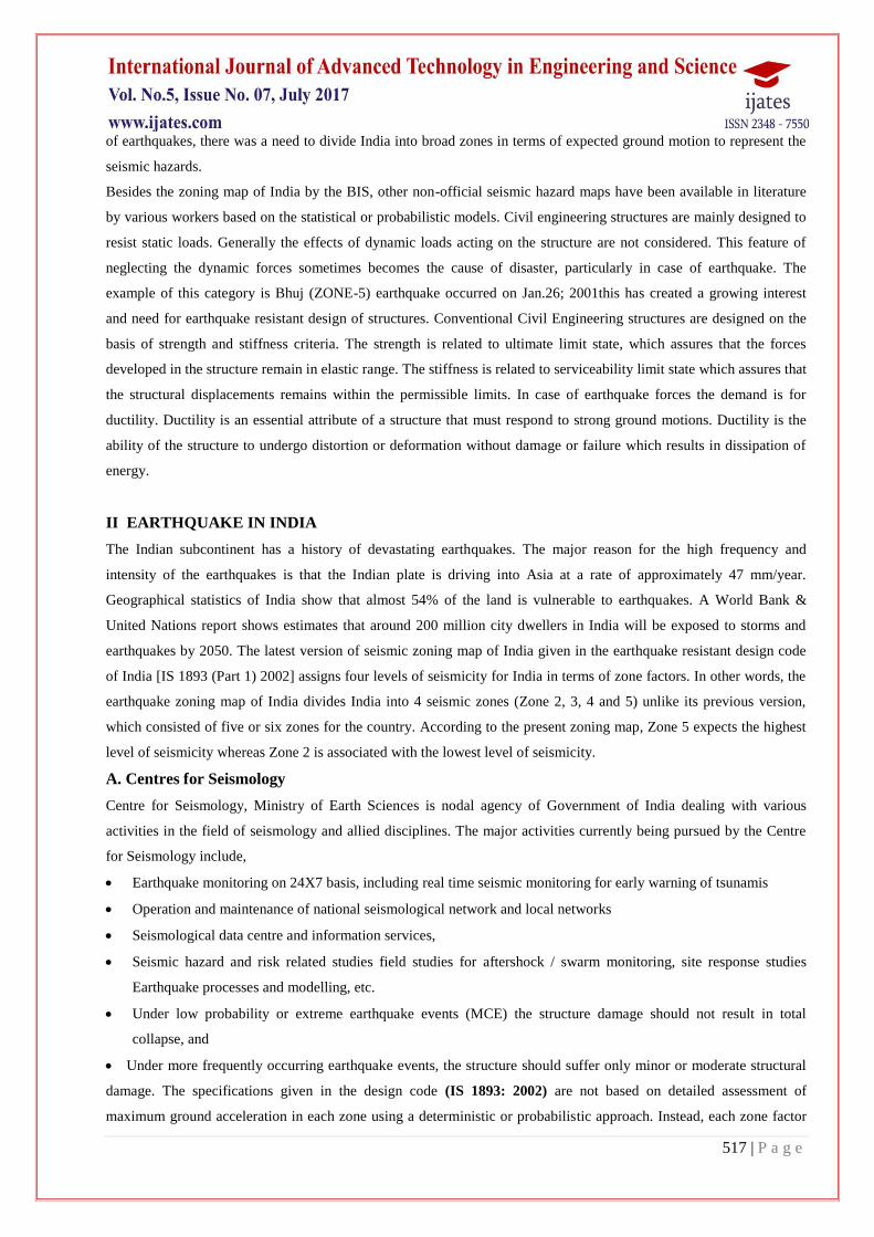
represents the effective period peak ground accelerations that may be generated during the maximum considered
earthquake ground motion in that zone
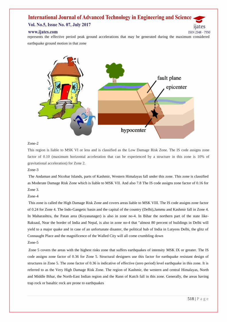
Zone-2
This region is liable to MSK VI or less and is classified as the Low Damage Risk Zone. The IS code assigns zone
factor of 0.10 (maximum horizontal acceleration that can be experienced by a structure in this zone is 10% of
gravitational acceleration) for Zone 2.
Zone-3
The Andaman and Nicobar Islands, parts of Kashmir, Western Himalayas fall under this zone. This zone is classified
as Moderate Damage Risk Zone which is liable to MSK VII. And also 7.8 The IS code assigns zone factor of 0.16 for
Zone 3.
Zone-4
This zone is called the High Damage Risk Zone and covers areas liable to MSK VIII. The IS code assigns zone factor
of 0.24 for Zone 4. The Indo-Gangetic basin and the capital of the country (Delhi),Jammu and Kashmir fall in Zone 4.
In Maharashtra, the Patan area (Koyananager) is also in zone no-4. In Bihar the northern part of the state like-
Raksaul, Near the border of India and Nepal, is also in zone no-4 that "almost 80 percent of buildings in Delhi will
yield to a major quake and in case of an unfortunate disaster, the political hub of India in Lutyens Delhi, the glitz of
Connaught Place and the magnificence of the Walled City will all come crumbling down
Zone-5
Zone 5 covers the areas with the highest risks zone that suffers earthquakes of intensity MSK IX or greater. The IS
code assigns zone factor of 0.36 for Zone 5. Structural designers use this factor for earthquake resistant design of
structures in Zone 5. The zone factor of 0.36 is indicative of effective (zero period) level earthquake in this zone. It is
referred to as the Very High Damage Risk Zone. The region of Kashmir, the western and central Himalayas, North
and Middle Bihar, the North-East Indian region and the Rann of Kutch fall in this zone. Generally, the areas having
trap rock or basaltic rock are prone to earthquakes
519 | P a g e
.
III. LITERATURE REVIEW
Events recorded so far in India in terms of death toll, damage to infrastructure and devastation in the last fifty years.
The major cities affected by the earthquake are Bhuj, Anjar, Bhachau, Gandhidham, Morbi, Rajnagar etc. where
majority of the causalities and damages occurred. Various types of structures reveal weakness in the form of design
and planning practices, inadequate analysis, design deficiency and even poor quality of construction. Reinforced
concrete multi-storied buildings in India for the first time have been subjected to a strong ground motion shaking in
Bhuj earthquake (January 26, 2001). It has been observed that the principal reasons of failure may be accounted to
soft stories, floating columns, mass irregularities, poor quality of construction material and faulty construction
practices etc.
The building framing system is generally moment resisting, consisting of reinforced concrete slabs cast monolithically
with beams and columns on sallow isolated footing. The upper floors are generally constructed with infill walls made
of unreinforced bricks, cut stones or cement concrete blocks. In major commercial cities, the ground floor/basement is
often used for commercial and parking purposes, where the infill walls are omitted, resulting in soft or weak stories.
Most of the buildings have overhanging covered balconies of about 1.5 m span on higher floors. The architects often
erect a heavy beam from the exterior columns of the building to the end of the building on the first floor onwards. A
principal beam is provided at the end of the erected girder to create more parking spaces at the ground floor and
allowing more space on the upper floors. The upper floor balconies or other constructions are constructed on the
peripheral beams. The infill walls, which are present in the upper floors and absent in the ground floor, create a floating
box type situation.
Columns in the most of the buildings are of uniform size along the height of the buildings, with marginal change in the
grade of concrete and reinforcement in the ground floor. It is apparent that the columns are designed only for axial
load, without considering the effect of framing action and lateral loads. The ground floor columns are not cast up to the
bottom of the beam and gap of 200 mm 250 mm is left called as “topi” to accommodate the beam reinforcement, which
520 | P a g e
makes the construction more vulnerable. Due to congestion of reinforcement in this region, the compaction of concrete
is not properly done which results in poor quality of concrete and honeycombing. The longitudinal reinforcement is
often lap-spliced just above the floor slab. The spacing of transverse reinforcement overlap splice is same as elsewhere
in the column rather being closely spaced. There is no sign of special confinement reinforcement and ductile detailing
in the columns. This is a faulty design practice from seismic point of view.
The foundation in private buildings generally consists of an isolated footing with a depth of about 1.5 m for G+3
buildings and 2.7 m to 3.5 m for G+10 buildings. The plan sizes of footings are usually 1.2 m × 1.2 m, 1.8 m × 1.8 m
or 2.4 m × 2.4 m. There are no tie beams interconnecting the footing, and plinth beams connecting the column at the
ground storey level.
A. Effect of earthquake on code designed structures
The Bureau of Indian standards (BIS) has published two codes IS 1893 (Part 1): 2002 and IS 13920: 1993 for
earthquake resistant design of reinforced concrete buildings. The former code deals with the determination of forces
and general considerations for design of buildings while latter code deals with the detailing of reinforced concrete
structures for ductility. The government buildings follow the design code as a mandatory requirement. Therefore, the
performance of governmental buildings in the Bhuj earthquake has been better on account of code compliance. The
multi-storied (G+9) reinforced concrete building, residential quarters for regional passport office and Ayakar Bhawan
(G+3) RC building with part basement at Ahmedabad were constructed by central public works department (CPWD) in
the years 2000 and 1954 respectively. These two buildings sustained minor damage in the form of cracking of infill
brick wall. Both buildings were in working condition after the earthquake and were not required to be vacated.
Thus the design of buildings should be based on seismic codes. The multi-
storied reinforced buildings with vertical irregularities like soft storey construction and the buildings with floating
column should be designed on the basis of earthquake analysis.
B. Methods of Seismic Design
Based on the three criteria strength, stiffness and ductility the methods for seismic design are described below:
1. Lateral strength based design: This is most common seismic design approach adopted nowadays. It is based on
providing the structure with the minimum lateral strength to resist seismic loads, assuming that the structure will
behave adequately in the non-linear range. For this reason only some simple construction detail rules are needed to be
satisfied.
2. Displacement based design :In this method the structure is designed to possess adequate ductility so that it can
dissipate energy by yielding and survive the shock. This method operates directly with deformation quantities hence
gives better insight on the expected performance of the structures. The displacement based design approach has been
adopted by the seismic codes of many countries.
3. Capacity based design: In this design approach the structures are designed in such a way so that plastic hinges can
form only in predetermined positions and in predetermined sequences. The concept of this method is to avoid brittle
mode of failure. This is achieved by designing the brittle modes of failure to have higher strength than ductile modes.

521 | P a g e
4. Energy based design: This is the most promising and futuristic approach of earthquake resistant design. In this
approach it is assume that the total energy input is collectively resisted by kinetic energy, the elastic strain energy and
energy dissipated through plastic deformations and damping.
B. Seismic Analysis Procedures
Main features of seismic method of analysis based on Indian Standard 1893(part 1): 2002 are described as follows
1. Equivalent lateral force method: The Equivalent lateral force method is the simplest method of analysis and
requires less computational effort because the forces depend on the code based fundamental period of structures with
some empirical modifier. The design base shear shall first be computed as a whole, and then be distributed along the
height of buildings based on simple formulae appropriate for buildings with regular distribution of mass and stiffness.
The design lateral force obtained at each floor level shall be distributed to individual lateral load resisting elements
depending upon floor diaphragm action. The design lateral force or design base shear and the distribution are given by
some empirical formulae given in the I.S 1893.
2. Response Spectrum analysis: This method is applicable for those structures where modes other than the
fundamental one affect significantly the response of the structure. In this method the response of Multi degree of
freedom system is expressed as the superposition of modal response, each modal response being determined from the
spectral analysis of Single– degree of freedom system, which is then combined to compute the total response.
3. Elastic Time history analysis: A linear analysis, time history analysis over comes all disadvantages of modal
response spectrum provided nonlinear behaviour is not involved. The method requires greater computational efforts for
calculating the response at discrete times. One interesting advantage of this is that the relative signs of response
quantities are preserved in the response histories. Chandrasekaran and Rao (2002) investigated the design of multi-
storied RCC building for seismicity. Reinforced concrete multi-storied buildings are very complex to model as
structural systems for analysis. Usually, they are modelled as 2-D or 3-D frame system using finite beam element
IV) EARTHQUAKE DESIGN RESISTANCE
Earthquakes are most feared natural disasters. Unpredictable and sudden, earthquakes can strike anytime, anyplace,
resulting in loss of life and property. Also, the lack of any fool proof early warning systems to predict earthquakes
makes the situation even more complex. With about 59% of our country’s landmass precariously resting above active
seismic zones (i.e. Areas prone to earthquakes) besides structural collapse, causes human causalities. Ultratech cement
Ltd. as a part of its public awareness initiative has compiled a few proven construction tips that will help in making
buildings earthquake resistant and it turn would greatly minimize the loss to invaluable loss and property.
So, come, explore the tips and start building a safe abode to live in.
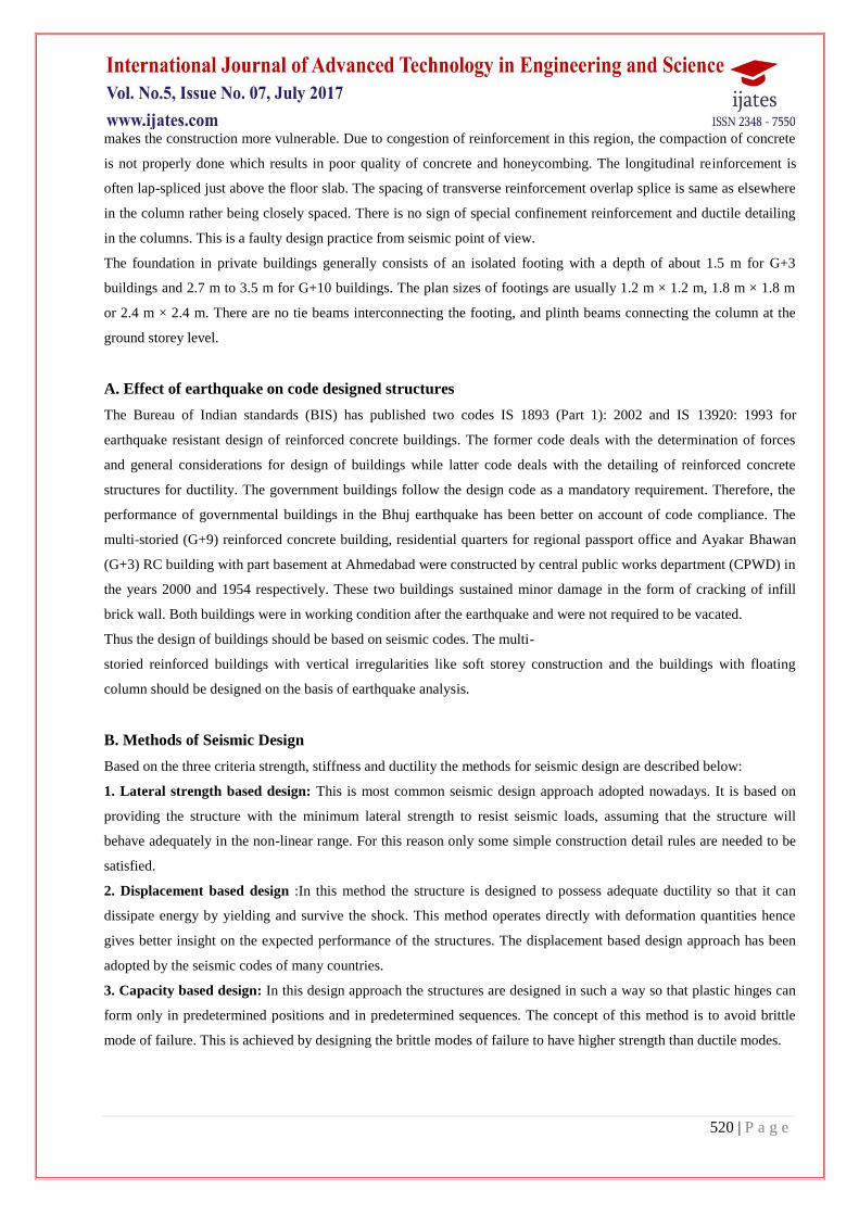
4.1 Shape of the Building
a)Buildings should be rectangle and symmetrical in plan.
b)Projections in the buildings should not exceed 1/5 the dimension of the building in the direction of projection.
c)In case of large extensions or portions of different height, it is advisable to separate the buildings with a gap of
minimum 25mm.
522 | P a g e
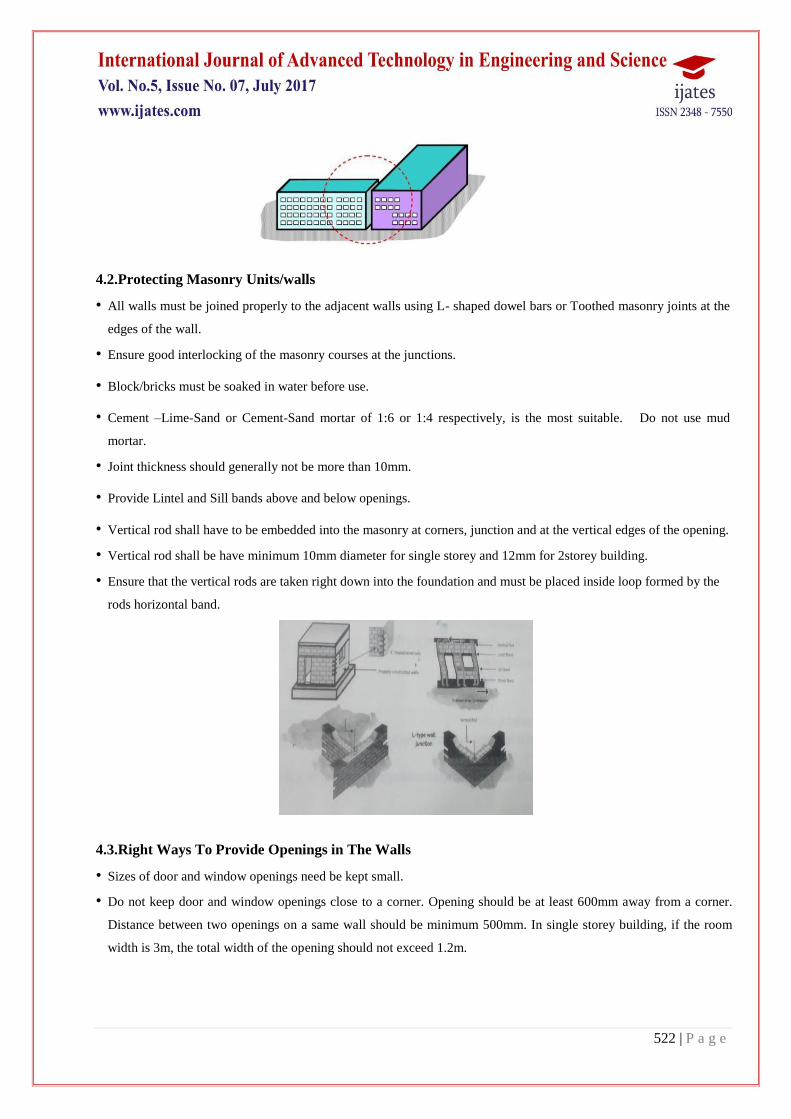
4.2.Protecting Masonry Units/walls
• All walls must be joined properly to the adjacent walls using L- shaped dowel bars or Toothed masonry joints at the
edges of the wall.
• Ensure good interlocking of the masonry courses at the junctions.
• Block/bricks must be soaked in water before use.
• Cement –Lime-Sand or Cement-Sand mortar of 1:6 or 1:4 respectively, is the most suitable. Do not use mud
mortar.
• Joint thickness should generally not be more than 10mm.
• Provide Lintel and Sill bands above and below openings.
• Vertical rod shall have to be embedded into the masonry at corners, junction and at the vertical edges of the opening.
• Vertical rod shall be have minimum 10mm diameter for single storey and 12mm for 2storey building.
• Ensure that the vertical rods are taken right down into the foundation and must be placed inside loop formed by the
rods horizontal band.
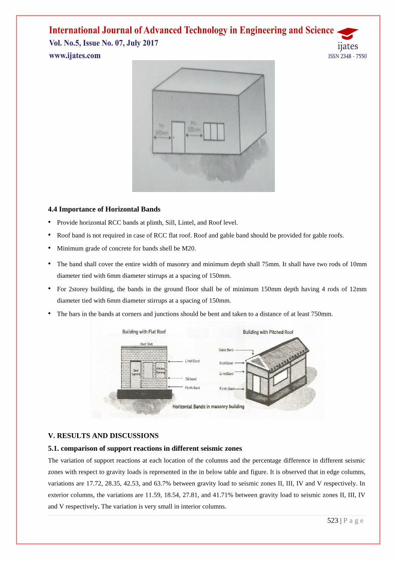
4.3.Right Ways To Provide Openings in The Walls
• Sizes of door and window openings need be kept small.
• Do not keep door and window openings close to a corner. Opening should be at least 600mm away from a corner.
Distance between two openings on a same wall should be minimum 500mm. In single storey building, if the room
width is 3m, the total width of the opening should not exceed 1.2m.
523 | P a g e
4.4 Importance of Horizontal Bands
• Provide horizontal RCC bands at plinth, Sill, Lintel, and Roof level.
• Roof band is not required in case of RCC flat roof. Roof and gable band should be provided for gable roofs.
• Minimum grade of concrete for bands shell be M20.
• The band shall cover the entire width of masonry and minimum depth shall 75mm. It shall have two rods of 10mm
diameter tied with 6mm diameter stirrups at a spacing of 150mm.
• For 2storey building, the bands in the ground floor shall be of minimum 150mm depth having 4 rods of 12mm
diameter tied with 6mm diameter stirrups at a spacing of 150mm.
• The bars in the bands at corners and junctions should be bent and taken to a distance of at least 750mm.
V. RESULTS AND DISCUSSIONS
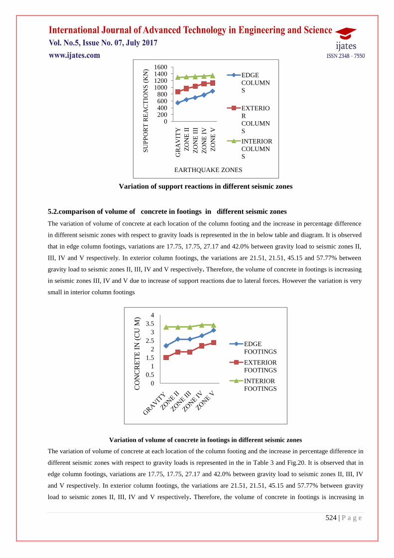
5.1. comparison of support reactions in different seismic zones
The variation of support reactions at each location of the columns and the percentage difference in different seismic
zones with respect to gravity loads is represented in the in below table and figure. It is observed that in edge columns,
variations are 17.72, 28.35, 42.53, and 63.7% between gravity load to seismic zones II, III, IV and V respectively. In
exterior columns, the variations are 11.59, 18.54, 27.81, and 41.71% between gravity load to seismic zones II, III, IV
and V respectively. The variation is very small in interior columns.
524 | P a g e
Variation of support reactions in different seismic zones
5.2.comparison of volume of concrete in footings in different seismic zones
The variation of volume of concrete at each location of the column footing and the increase in percentage difference
in different seismic zones with respect to gravity loads is represented in the in below table and diagram. It is observed
that in edge column footings, variations are 17.75, 17.75, 27.17 and 42.0% between gravity load to seismic zones II,
III, IV and V respectively. In exterior column footings, the variations are 21.51, 21.51, 45.15 and 57.77% between
gravity load to seismic zones II, III, IV and V respectively. Therefore, the volume of concrete in footings is increasing
in seismic zones III, IV and V due to increase of support reactions due to lateral forces. However the variation is very
small in interior column footings
Variation of volume of concrete in footings in different seismic zones
The variation of volume of concrete at each location of the column footing and the increase in percentage difference in
different seismic zones with respect to gravity loads is represented in the in Table 3 and Fig.20. It is observed that in
edge column footings, variations are 17.75, 17.75, 27.17 and 42.0% between gravity load to seismic zones II, III, IV
and V respectively. In exterior column footings, the variations are 21.51, 21.51, 45.15 and 57.77% between gravity
load to seismic zones II, III, IV and V respectively. Therefore, the volume of concrete in footings is increasing in
0200400600800
1000120014001600
GR
AV
ITY
ZO
NE
II
ZO
NE
III
ZO
NE
IV
ZO
NE
V
SU
PP
OR
T R
EA
CT
ION
S (
KN
)
EARTHQUAKE ZONES
EDGE
COLUMN
S
EXTERIO
R
COLUMN
S
INTERIOR
COLUMN
S
0
0.5
1
1.5
2
2.5
3
3.5
4
CO
NC
RE
TE
IN
(C
U M
)
EDGE
FOOTINGS
EXTERIOR
FOOTINGS
INTERIOR
FOOTINGS
525 | P a g e
seismic zones III, IV and V due to increase of support reactions due to lateral forces. However the variation is very
small in interior column footings.
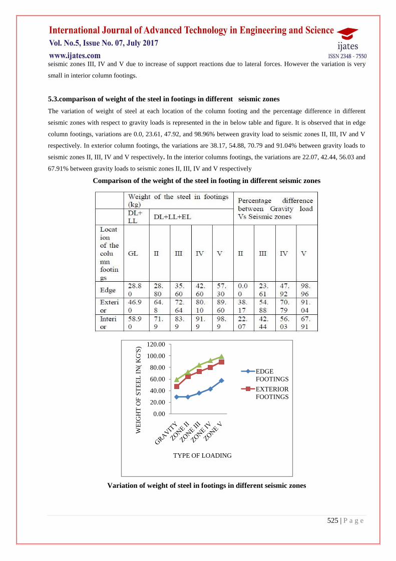
5.3.comparison of weight of the steel in footings in different seismic zones
The variation of weight of steel at each location of the column footing and the percentage difference in different
seismic zones with respect to gravity loads is represented in the in below table and figure. It is observed that in edge
column footings, variations are 0.0, 23.61, 47.92, and 98.96% between gravity load to seismic zones II, III, IV and V
respectively. In exterior column footings, the variations are 38.17, 54.88, 70.79 and 91.04% between gravity loads to
seismic zones II, III, IV and V respectively. In the interior columns footings, the variations are 22.07, 42.44, 56.03 and
67.91% between gravity loads to seismic zones II, III, IV and V respectively
Comparison of the weight of the steel in footing in different seismic zones
Variation of weight of steel in footings in different seismic zones
0.00
20.00
40.00
60.00
80.00
100.00
120.00
WE
IGH
T O
F S
TE
EL
IN
( K
G'S
)
TYPE OF LOADING
EDGE
FOOTINGS
EXTERIOR
FOOTINGS
526 | P a g e
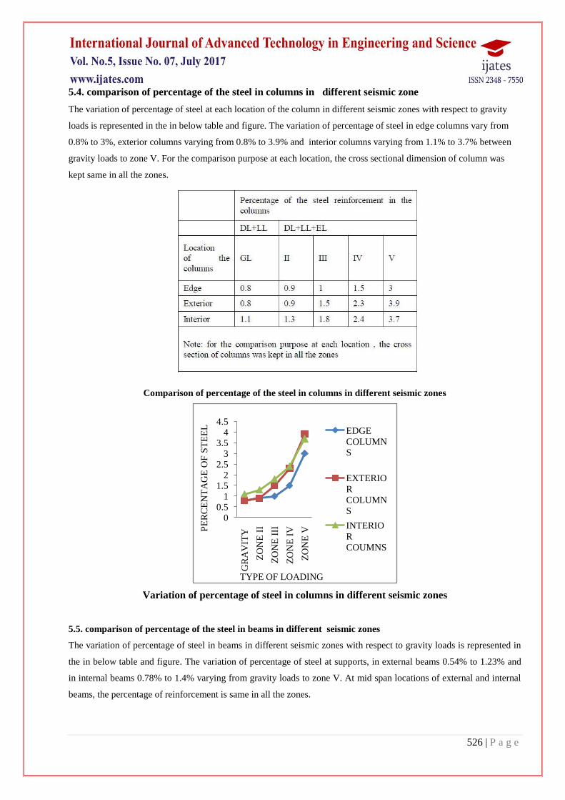
5.4. comparison of percentage of the steel in columns in different seismic zone
The variation of percentage of steel at each location of the column in different seismic zones with respect to gravity
loads is represented in the in below table and figure. The variation of percentage of steel in edge columns vary from
0.8% to 3%, exterior columns varying from 0.8% to 3.9% and interior columns varying from 1.1% to 3.7% between
gravity loads to zone V. For the comparison purpose at each location, the cross sectional dimension of column was
kept same in all the zones.
Comparison of percentage of the steel in columns in different seismic zones
Variation of percentage of steel in columns in different seismic zones
5.5. comparison of percentage of the steel in beams in different seismic zones
The variation of percentage of steel in beams in different seismic zones with respect to gravity loads is represented in
the in below table and figure. The variation of percentage of steel at supports, in external beams 0.54% to 1.23% and
in internal beams 0.78% to 1.4% varying from gravity loads to zone V. At mid span locations of external and internal
beams, the percentage of reinforcement is same in all the zones.
00.5
11.5
22.5
33.5
44.5
GR
AV
ITY
ZO
NE
II
ZO
NE
III
ZO
NE
IV
ZO
NE
VPE
RC
EN
TA
GE
OF
ST
EE
L
TYPE OF LOADING
EDGE
COLUMN
S
EXTERIO
R
COLUMN
S
INTERIO
R
COUMNS

527 | P a g e
Comparison of percentage of the steel in beams in different seismic zones
Percentage of steel in beams in different seismic zones
5.6.Comparison of Weight of the Steel in Beams in Different Seismic Zones
The variation of weight of steel at each location of the beams and the percentage difference in different seismic zones
with respect to gravity loads is represented in the in Table 6 and Fig.8. It is observed that in external beams, variations
are 4.38, 13.8, 31.3, and 49.6% between gravity loads to seismic zones II, III, IV and V respectively. In the internal
beams, the variations are 3.07, 15.3, 20.2 and 53.3% between gravity loads to seismic zones II, III, IV and V
respectively.
Variation of weight of steel in beams in different seismic zones
0
0.2
0.4
0.6
0.8
1
1.2
1.4
1.6
PE
RC
EN
TA
GE
O
F S
TE
EL
TYPE OF LOADING
AT
SUPPORTS
EXTERNA
L BEAMSAT
SUPPORTS
INTERNAL
BEAMS
050
100150200250300
WE
IGH
T O
F S
TE
EL
IN
(KG
'S)
TYPE OF LOADING
EXTERNAL
BEAMS
528 | P a g e
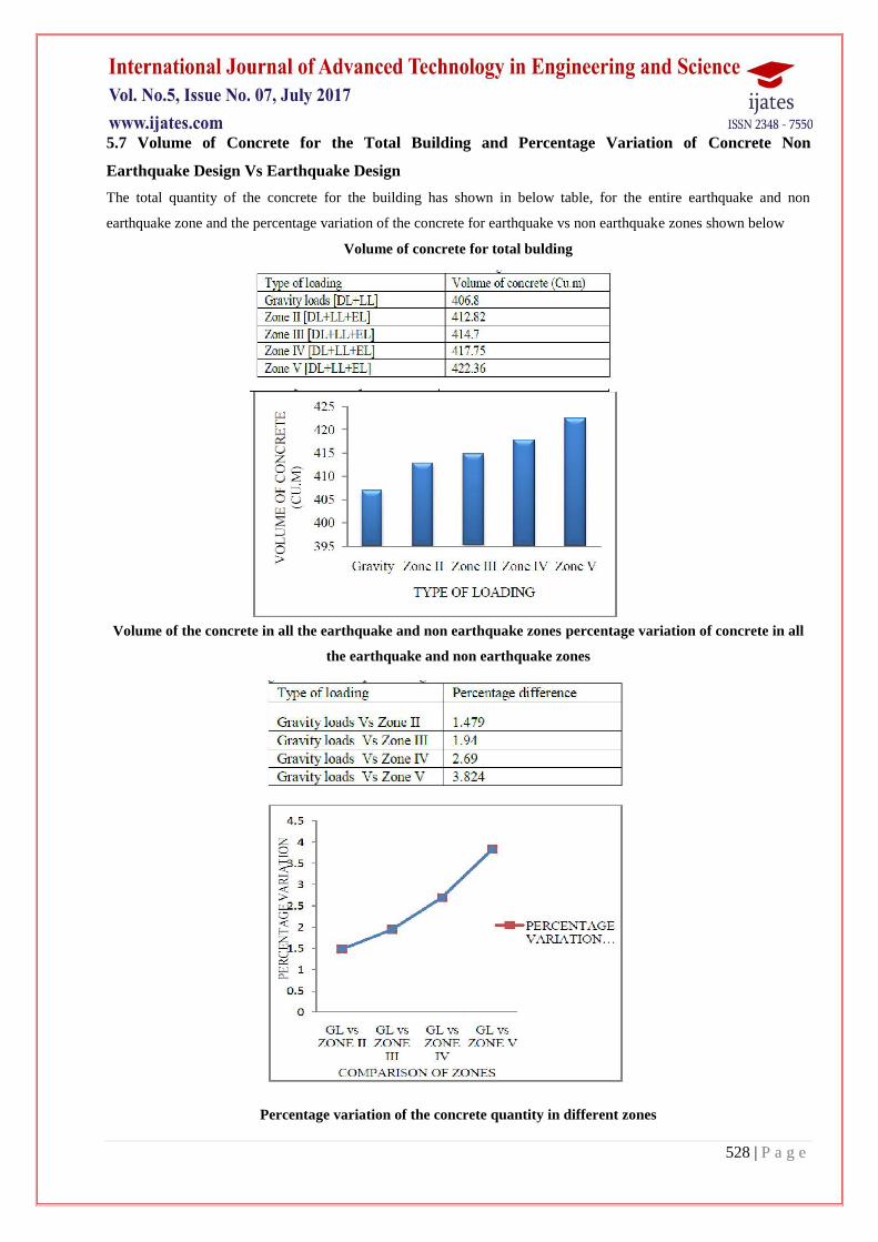
5.7 Volume of Concrete for the Total Building and Percentage Variation of Concrete Non
Earthquake Design Vs Earthquake Design
The total quantity of the concrete for the building has shown in below table, for the entire earthquake and non
earthquake zone and the percentage variation of the concrete for earthquake vs non earthquake zones shown below
Volume of concrete for total bulding
Volume of the concrete in all the earthquake and non earthquake zones percentage variation of concrete in all
the earthquake and non earthquake zones
Percentage variation of the concrete quantity in different zones
529 | P a g e
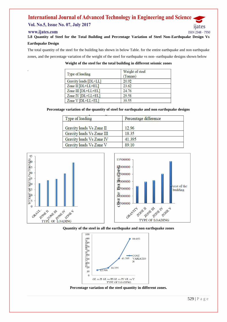
5.8 Quantity of Steel for the Total Building and Percentage Variation of Steel Non-Earthquake Design Vs
Earthquake Design
The total quantity of the steel for the building has shown in below Table. for the entire earthquake and non earthquake
zones, and the percentage variation of the weight of the steel for earthquake vs non- earthquake designs shown below
Weight of the steel for the total building in different seismic zones
.
Percentage variation of the quantity of steel for earthquake and non earthquake designs
Quantity of the steel in all the earthquake and non earthquake zones
Percentage variation of the steel quantity in different zones.
530 | P a g e
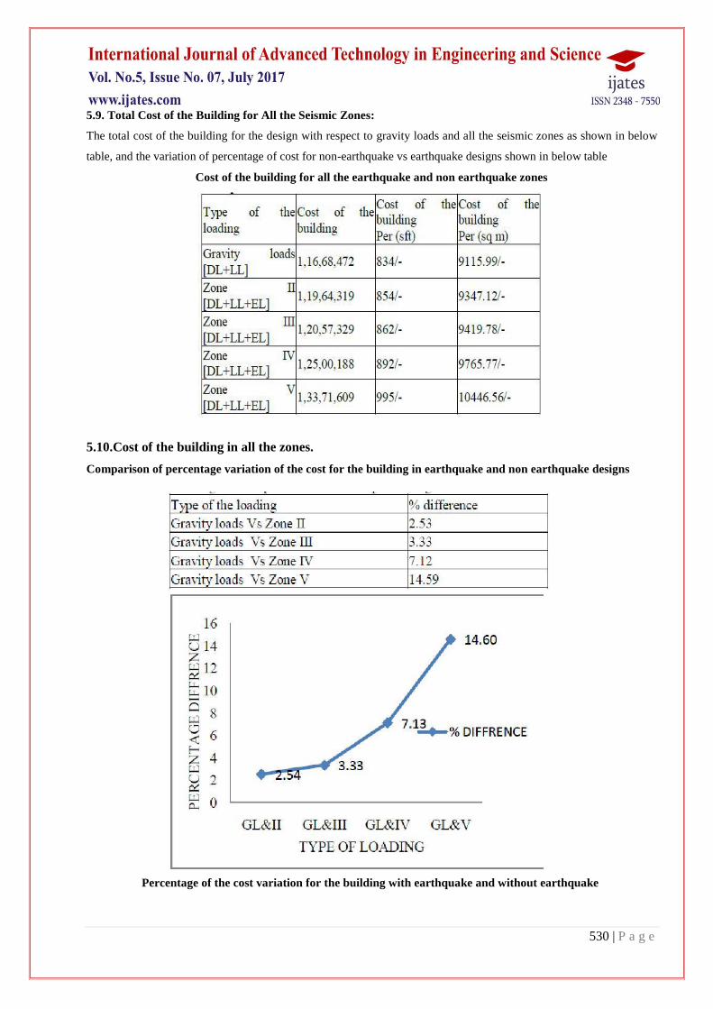
5.9. Total Cost of the Building for All the Seismic Zones:
The total cost of the building for the design with respect to gravity loads and all the seismic zones as shown in below
table, and the variation of percentage of cost for non-earthquake vs earthquake designs shown in below table
Cost of the building for all the earthquake and non earthquake zones
5.10.Cost of the building in all the zones.
Comparison of percentage variation of the cost for the building in earthquake and non earthquake designs
Percentage of the cost variation for the building with earthquake and without earthquake
531 | P a g e
VI) STUDY OF FUTURE SCOPE
Giving awareness to the people for safe design as earthquake does not kill people improperly designed structures
do.
This standard (Part 1) deals with assessment of seismic loads on various structures and earthquake resistant design
of buildings. Its basic provisions are applicable to buildings; elevated structures; industrial and stack like structures;
bridges; concrete masonry and earth dams; embankments and retaining walls and other structures.
Temporary elements such as scaffolding, temporary excavations need not be designed for earthquake forces.
This standard does not deal with the construction features relating to earthquake resistant design in buildings and
other structures. For guidance on earthquake resistant construction of buildings, reference may be made to the
following Indian Standards: IS 4326, IS 13827, IS 13828, IS 13920 and IS 13935.
VII. CONCLUSION
The variation of support reactions in exterior columns increasing from 11.60% to 41.75% and in edge columns
increasing from 17.72% to 64.0% in seismic Zones II to V. However the variations of support reactions are very
small in interior columns.
The volume of concrete in exterior and edge column footings is increasing in seismic zones III, IV and V due to
increase of support reactions with the effect of lateral forces. However the variation is very small in interior column
footings.
The percentage variation of steel in edge, exterior and interior columns varies from 0.8-3%, 0.8-4% and 1.1-4.0%
between gravity loads to seismic zone V respectively.
In the external and internal beams, the percentage of bottom middle reinforcement is almost same for both
earthquake and non-earthquake designs.
Percentage variation of total concrete quantity for the whole structure, between gravity load and seismic zones II,
III, IV and V varies as 1.4, 2.0, 2.7 and 4.0 respectively.
VIII. REFERENCES
Mohit Sharma, Dr. SavitaMaru. IOSR Journal of Mechanical and Civil Engineering, Volume 11, Issue 1. Ver. II
(Jan-2014).
IS: 1893-2002 (part-1) “criteria for earthquake resistant design of structures” fifth revision, Bureau of Indian
Standards, New Delhi.
IS: 456-2000 (Indian Standard Plain Reinforced Concrete Code of Practice) – Fourth Revision.
IS: 875-1987 (part-1) for Dead Loads, code of practice of Design loads (other than earthquake) for buildings and
structures.
IS: 875-1987 (part-2) for Live Loads or Imposed Loads, code of practice of Design loads (other than earthquake)
for buildings and structures.
IS: 875-1987 (part-3) for Wind Loads, code of practice of Design loads (other than earthquake) for buildings and
structures.
IS 13920-1993 for Ductile Detailing Reinforced Concrete Structures subject to seismic forces, Bureau of Indian
Standards, New Delhi.

532 | P a g e
Dr. S.K Duggal, Earthquake Resistance Design of Structure.
P. C. Varghese Advanced Reinforced Concrete Design, Second Edition