vibrational analysis of chimney equipped …ijates.com/images/short_pdf/1459432667_1221b.pdf ·...
TRANSCRIPT
321 | P a g e
VIBRATIONAL ANALYSIS OF CHIMNEY
EQUIPPED WITH STRAKES AND TUNE MASS
DAMPER.
Pratik Wadgave1, Chittaranjan Nayak
2
1,2Civil Department, VPCOE Baramati, SavitribaiPhule Pune University, (India)
ABSTRACT
Chimneys are the structures which are built to greater heights as tall slender structures. Any damage to
chimneys may result in shut down of plants and industries.Construction of tall chimneys needs the better
understanding of loads acting on them and of the structural behaviour, so that with the help of modern
construction equipment and technique such as slip form, reinforced concrete, the most favoured material for
chimney construction, could be used efficiently. The proper design and construction of such chimneys will
create self-standing structures to resist wind load and other forces acting on them. It is a common practice to
consider the effects of wind and earthquake separately in the design. Chimneys are more vulnerable to wind and
earthquake loads which may cause severe problem in power plants and major industries. However, if they are
located in higher seismic zone with lower wind speeds, then, seismic forces may become analogous, if not more,
than the wind loads may become analogous. It is designed for both along wind and across wind loads.
Chimney with strakes is a modern technique which is used in most of the chimney now-a-days. Another
technique which is used commonly is the use of Tune Mass Damper (TMD). Both these techniques are used to
minimize the vibration of chimney but in totally different phenomenon. In this paper the use of both the
techniques are done and corresponding vibrational analysis are done using Finite Element Method (SAP 2000).
To expand more on this research work vents are provided andanalysis is then carried out with strakes and TMD
for base shear, base moment and time period.
Keywords: Tune mass damper, strakes, stresses, moments and time period.
I. INTRODUCTION
Chimneys or stacks are used as a medium to transfer highly contaminated polluted gases to atmosphere at
greater heights. The main function of chimney is to take highly poisonous gases which are not acceptable at
ground level were taken to greater heights with sufficient velocities however, with the increment in height, the
wind actions on it become important as these produce very high stresses. Although chimneys do not present as a
great hazard to life and limb as buildings with high human capacity, damage to chimneys may result in shut
down of plants and industries. The chimney may be self-supporting or cable supported. Chimneys are more
vulnerable to wind and earthquake loads which may cause severe problem in power plants and major industries.
However, if they are located in higher seismic zone with lower wind speeds, then, seismic forces may become
analogous, if not more, than the wind loads may become analogous.
322 | P a g e
1.1 Methodology: The primary objective of this paper is to analyse the 90m chimney equipped with Strakes and
tune mass damper. This analysis varies as the height of strakes increases as 30m and 45m from top. The analysis
also varies with increase in damping percent as nominal, 5%, 10% and 15%. The analysis is then carried
forward with chimney equipped with both strakes and tune mass damper.
This further analysis is carried out in varies combinations of height of strakes and damping percentage of tune
mass damper with openings as air vent and door vent. Thus the comparison is made among them. The main
objectives of undertaking the present study are as follows.
To develop a model of chimney of 90m height, 6.4m diameter and 0.400m thickness in SAP 2000 as per
specification of chimney.
To analyse modelled chimney for time period of various cases and comparing it with corresponding models.
To develop relation between strakes height and time period of chimney with and without opening subjected
to seismic and wind loadings. To develop this relation height of strakes is increased
To develop relation between damping ratio, time period, base shear and base moment of chimney subjected
to seismic load and wind load. Also relation between tune mass damper and time period of chimney
subjected to seismic and wind load is to develop.
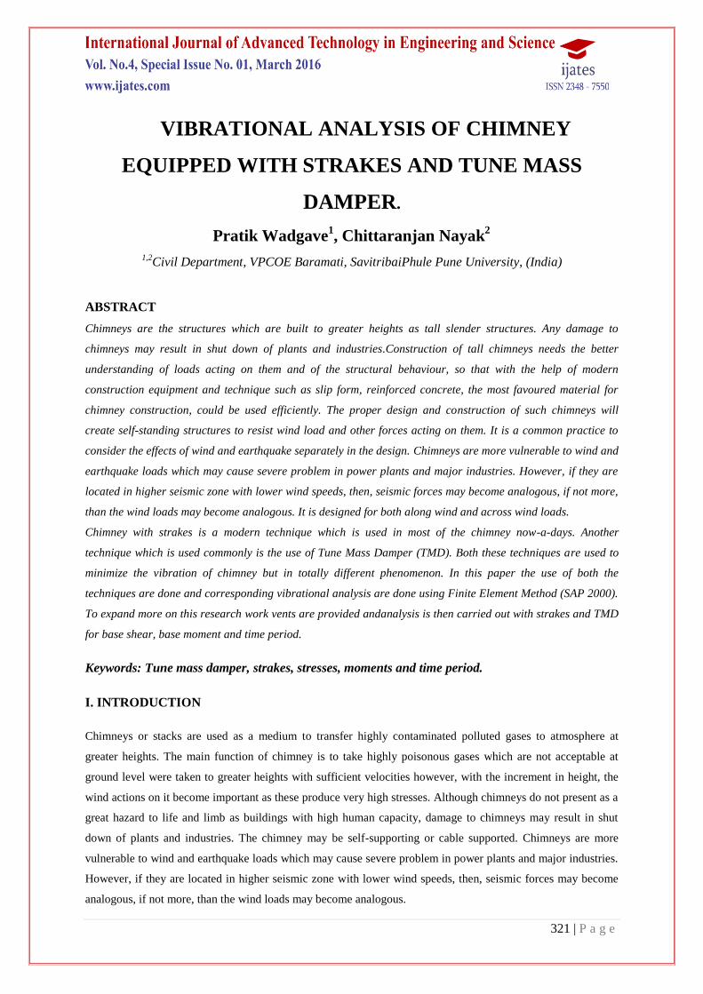
1.2 Structural description: Chimney is situated in zone IV and the top wind speed recorded is about 46 km/hr.
The height of the chimney to be constructed is about 90m and the internal diameter is about 6m. Shell thickness
of chimney is about 0.4m and external diameter is 6.4m. An air vent is also provided to facilitate gas thrust out
of the chimney. This chimney is to be analysed for both seismic effects and for wind effects. Also there is a
provision for the application of Tune Mass Damper (TMD) and strakes to minimise the vibrations caused due to
seismic forces and wind forces. Structural damping is to be considered as 5% of total weight of chimney.
Figure 1 chimney modelled in SAP2000
II. RESULTS:
Case i - chimney without opening for different strakes height and damping ratio.
The chimney without opening for without strakes, 30m and 45m strakes height and damping ratios as without
damping, 5%, 10% and 15% is analysed as follows.
323 | P a g e
Case I (a): Chimney without opening and without strakes and for damping ratio as without damping, 5%, 10%
and 15%.
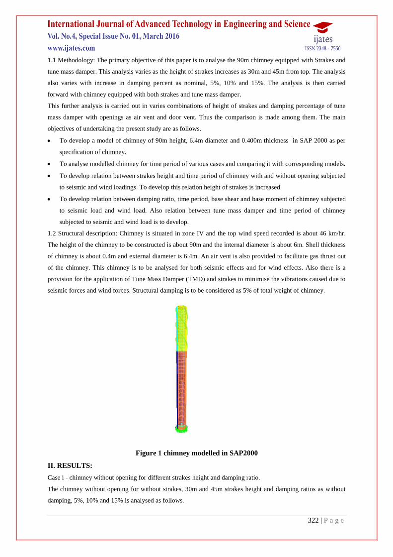
Figure 2 shows three mode shapes versus their time period in seconds for without strakes and for damping ratios
as without damping, 5%, 10% and 15%.
Figure 2 Comparison of time period for without strakes
It is observed from figure 2 it is clear that the time period decreases as the damping ratio increases
where strakes height is same for this case as without strakes. The time period drops dramatically between 0%
and 15% of damping ratio by 76% for first mode and is almost same for second mode. For third mode this
difference reduces to 45.38%.
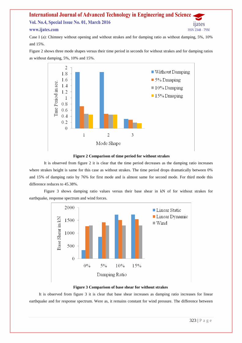
Figure 3 shows damping ratio values versus their base shear in kN of for without strakes for
earthquake, response spectrum and wind forces.
Figure 3 Comparison of base shear for without strakes
It is observed from figure 3 it is clear that base shear increases as damping ratio increases for linear
earthquake and for response spectrum. Were as, it remains constant for wind pressure. The difference between
324 | P a g e
0% and 15% damping ratio for linear earth quake is about 78.78% and that for response spectrum is about
13.33%.
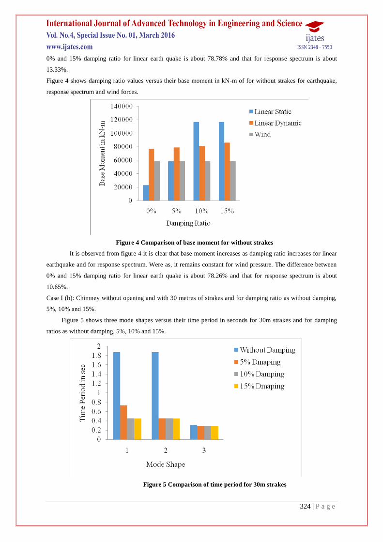
Figure 4 shows damping ratio values versus their base moment in kN-m of for without strakes for earthquake,
response spectrum and wind forces.
Figure 4 Comparison of base moment for without strakes
It is observed from figure 4 it is clear that base moment increases as damping ratio increases for linear
earthquake and for response spectrum. Were as, it remains constant for wind pressure. The difference between
0% and 15% damping ratio for linear earth quake is about 78.26% and that for response spectrum is about
10.65%.
Case I (b): Chimney without opening and with 30 metres of strakes and for damping ratio as without damping,
5%, 10% and 15%.
Figure 5 shows three mode shapes versus their time period in seconds for 30m strakes and for damping
ratios as without damping, 5%, 10% and 15%.
Figure 5 Comparison of time period for 30m strakes
325 | P a g e
It is observed from figure 5 it is clear that the time period decreases as the damping ratio increases where strakes
height is same for this case as 30m. The time period drops dramatically between 0% and 15% of damping ratio
by 75.87% for first mode and is almost same for second mode. For third mode this difference reduces to 487%.
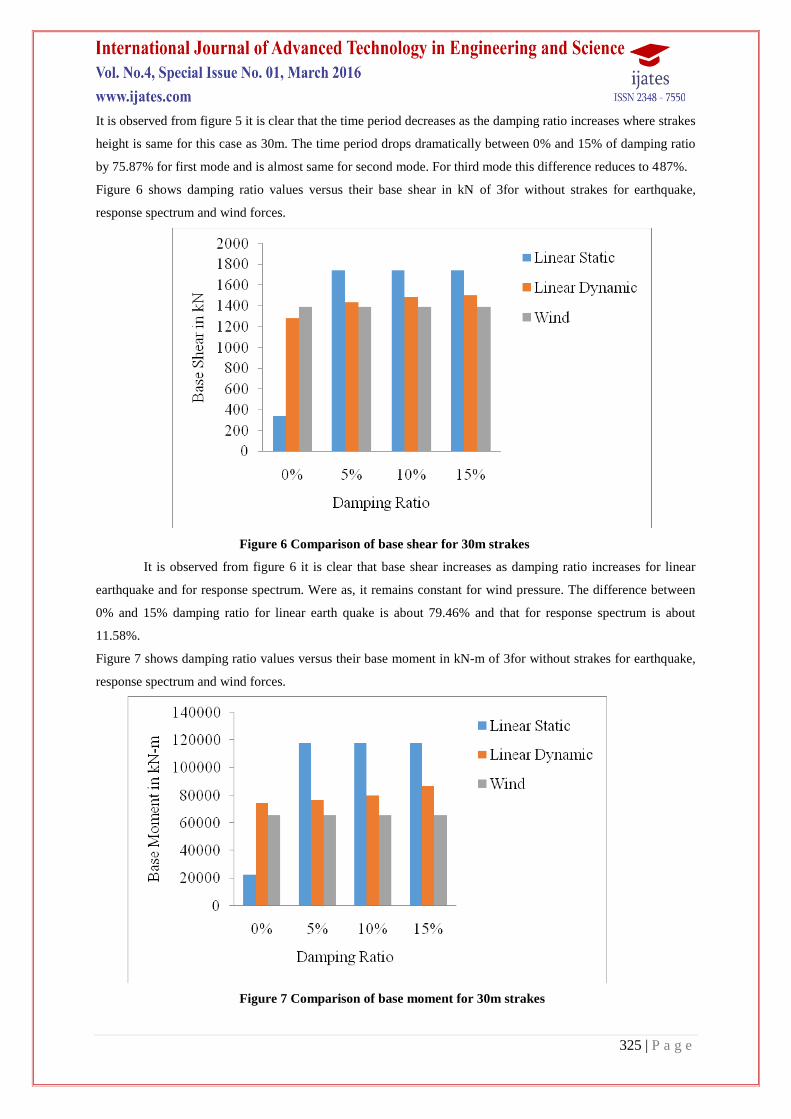
Figure 6 shows damping ratio values versus their base shear in kN of 3for without strakes for earthquake,
response spectrum and wind forces.
Figure 6 Comparison of base shear for 30m strakes
It is observed from figure 6 it is clear that base shear increases as damping ratio increases for linear
earthquake and for response spectrum. Were as, it remains constant for wind pressure. The difference between
0% and 15% damping ratio for linear earth quake is about 79.46% and that for response spectrum is about
11.58%.
Figure 7 shows damping ratio values versus their base moment in kN-m of 3for without strakes for earthquake,
response spectrum and wind forces.
Figure 7 Comparison of base moment for 30m strakes
326 | P a g e
It is observed from figure 7 it is clear that base moment increases as damping ratio increases for linear
earthquake and for response spectrum. Were as, it remains constant for wind pressure. The difference between
0% and 15% damping ratio for linear earth quake is about 80.06% and that for response spectrum is about
112%.
Case I (c): Chimney without opening and with 45 metres of strakes and for damping ratio as without damping,
5%, 10% and 15%.
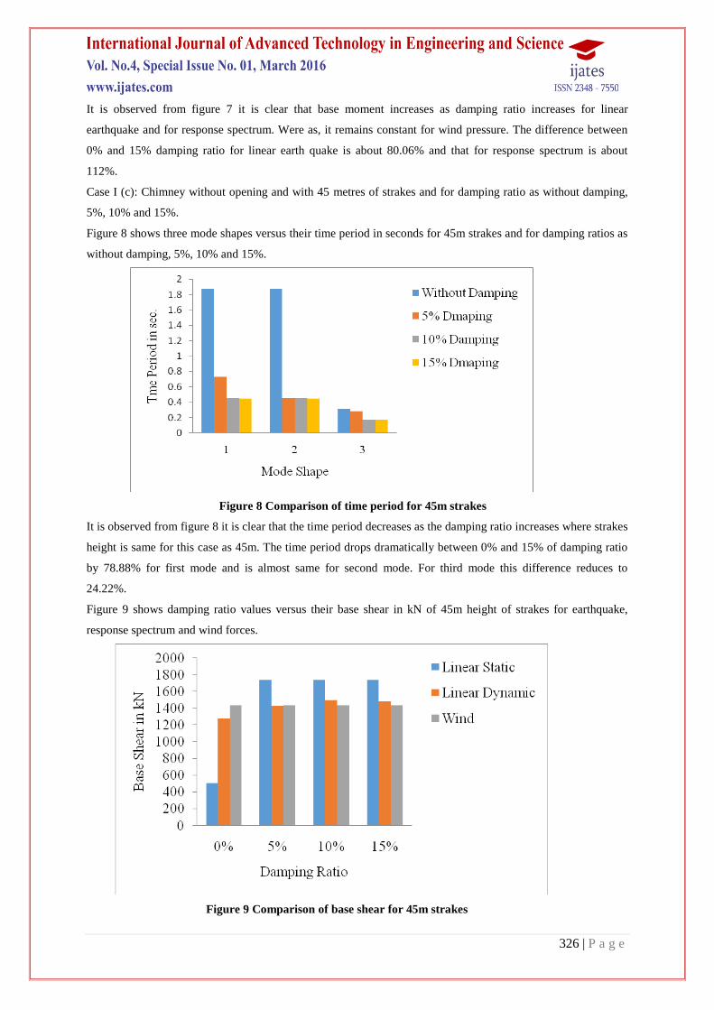
Figure 8 shows three mode shapes versus their time period in seconds for 45m strakes and for damping ratios as
without damping, 5%, 10% and 15%.
Figure 8 Comparison of time period for 45m strakes
It is observed from figure 8 it is clear that the time period decreases as the damping ratio increases where strakes
height is same for this case as 45m. The time period drops dramatically between 0% and 15% of damping ratio
by 78.88% for first mode and is almost same for second mode. For third mode this difference reduces to
24.22%.
Figure 9 shows damping ratio values versus their base shear in kN of 45m height of strakes for earthquake,
response spectrum and wind forces.
Figure 9 Comparison of base shear for 45m strakes
327 | P a g e
It is observed from figure 9 it is clear that base shear increases as damping ratio increases for linear
earthquake and for response spectrum. Were as, it remains constant for wind pressure. The difference between
0% and 15% damping ratio for linear earth quake is about 70.51% and that for response spectrum is about
10.56%.
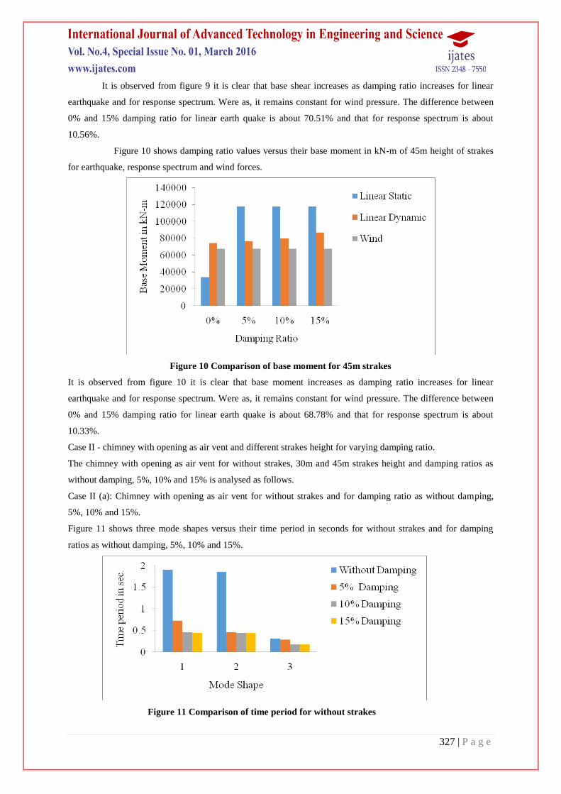
Figure 10 shows damping ratio values versus their base moment in kN-m of 45m height of strakes
for earthquake, response spectrum and wind forces.
Figure 10 Comparison of base moment for 45m strakes
It is observed from figure 10 it is clear that base moment increases as damping ratio increases for linear
earthquake and for response spectrum. Were as, it remains constant for wind pressure. The difference between
0% and 15% damping ratio for linear earth quake is about 68.78% and that for response spectrum is about
10.33%.
Case II - chimney with opening as air vent and different strakes height for varying damping ratio.
The chimney with opening as air vent for without strakes, 30m and 45m strakes height and damping ratios as
without damping, 5%, 10% and 15% is analysed as follows.
Case II (a): Chimney with opening as air vent for without strakes and for damping ratio as without damping,
5%, 10% and 15%.
Figure 11 shows three mode shapes versus their time period in seconds for without strakes and for damping
ratios as without damping, 5%, 10% and 15%.
Figure 11 Comparison of time period for without strakes
328 | P a g e
It is observed from figure 11 it is clear that the time period decreases as the damping ratio increases where
strakes height is same for this case as without strakes. The time period drops dramatically between 0% and 15%
of damping ratio by 77.36% for first mode and is almost same for second mode. For third mode this difference
reduces to 43.71%.
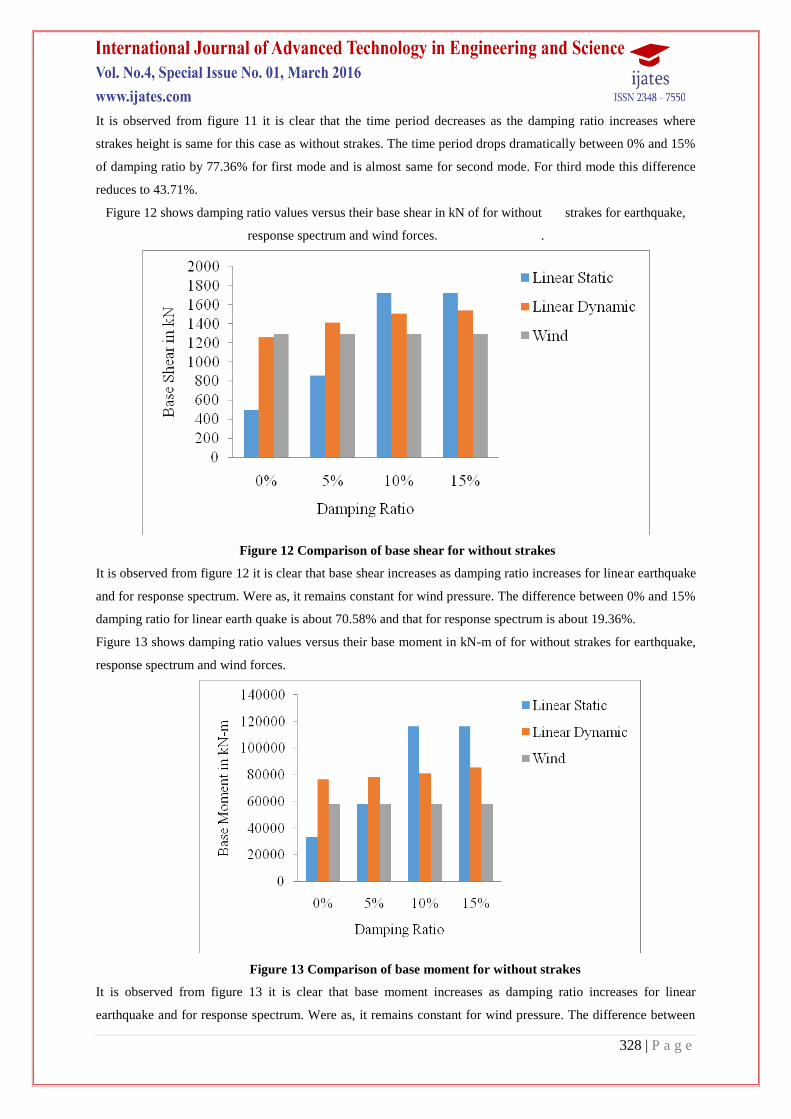
Figure 12 shows damping ratio values versus their base shear in kN of for without strakes for earthquake,
response spectrum and wind forces. .
Figure 12 Comparison of base shear for without strakes
It is observed from figure 12 it is clear that base shear increases as damping ratio increases for linear earthquake
and for response spectrum. Were as, it remains constant for wind pressure. The difference between 0% and 15%
damping ratio for linear earth quake is about 70.58% and that for response spectrum is about 19.36%.
Figure 13 shows damping ratio values versus their base moment in kN-m of for without strakes for earthquake,
response spectrum and wind forces.
Figure 13 Comparison of base moment for without strakes
It is observed from figure 13 it is clear that base moment increases as damping ratio increases for linear
earthquake and for response spectrum. Were as, it remains constant for wind pressure. The difference between
329 | P a g e
0% and 15% damping ratio for linear earth quake is about 70.33% and that for response spectrum is about
18.77%.
Case II (b): Chimney with opening as air vent for 30 metres of strakes and for damping ratio as without
damping, 5%, 10% and 15%.
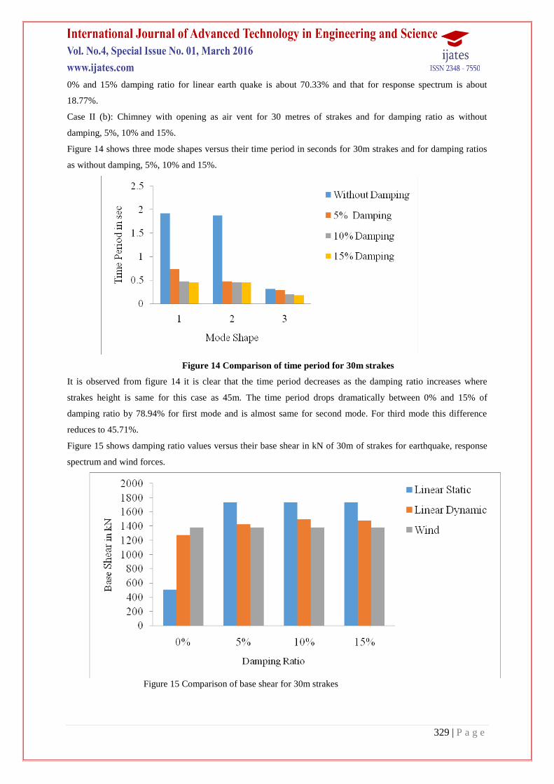
Figure 14 shows three mode shapes versus their time period in seconds for 30m strakes and for damping ratios
as without damping, 5%, 10% and 15%.
Figure 14 Comparison of time period for 30m strakes
It is observed from figure 14 it is clear that the time period decreases as the damping ratio increases where
strakes height is same for this case as 45m. The time period drops dramatically between 0% and 15% of
damping ratio by 78.94% for first mode and is almost same for second mode. For third mode this difference
reduces to 45.71%.
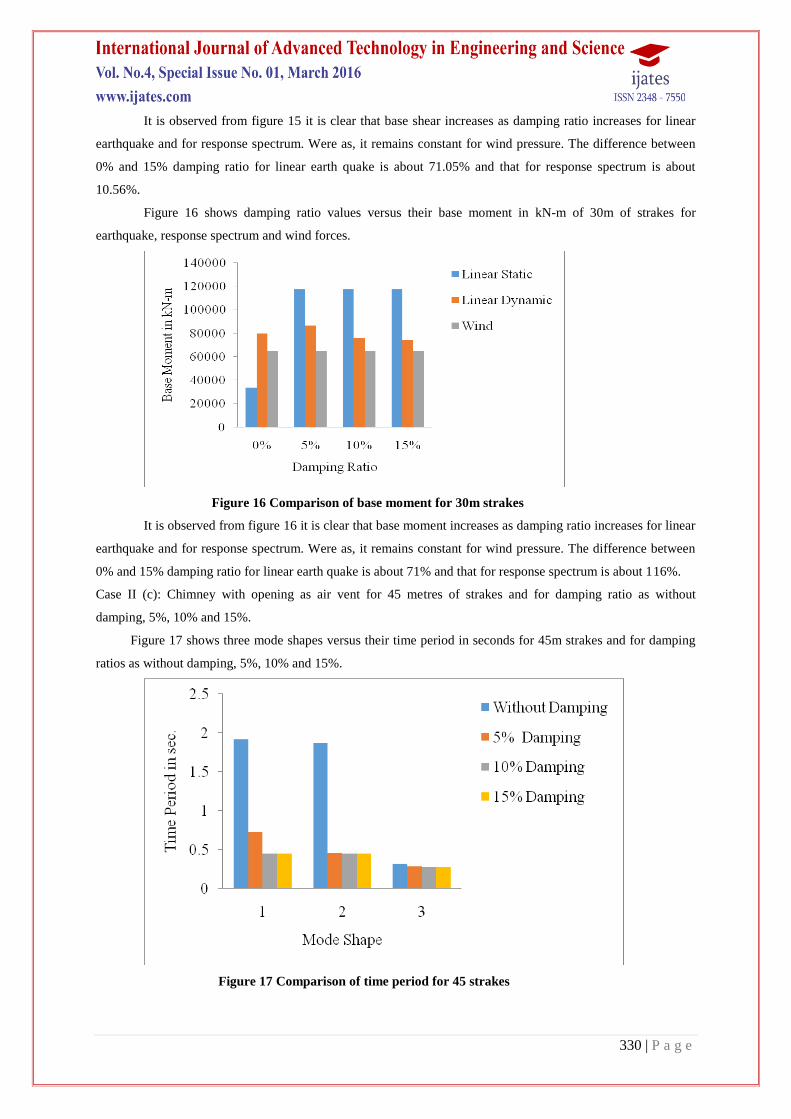
Figure 15 shows damping ratio values versus their base shear in kN of 30m of strakes for earthquake, response
spectrum and wind forces.
Figure 15 Comparison of base shear for 30m strakes
330 | P a g e
It is observed from figure 15 it is clear that base shear increases as damping ratio increases for linear
earthquake and for response spectrum. Were as, it remains constant for wind pressure. The difference between
0% and 15% damping ratio for linear earth quake is about 71.05% and that for response spectrum is about
10.56%.
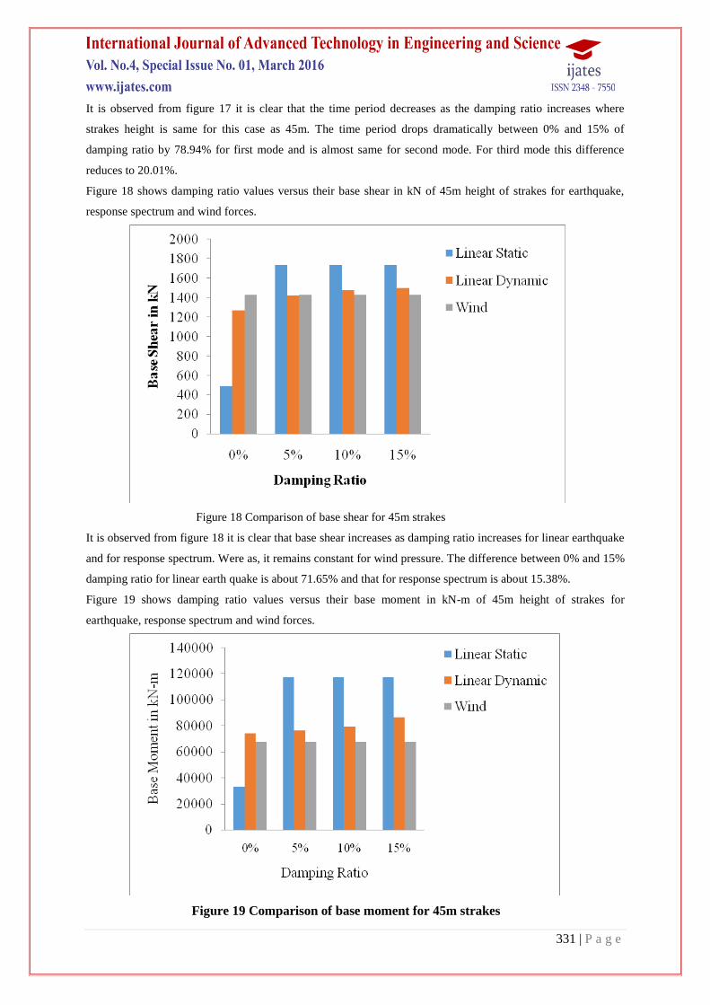
Figure 16 shows damping ratio values versus their base moment in kN-m of 30m of strakes for
earthquake, response spectrum and wind forces.
Figure 16 Comparison of base moment for 30m strakes
It is observed from figure 16 it is clear that base moment increases as damping ratio increases for linear
earthquake and for response spectrum. Were as, it remains constant for wind pressure. The difference between
0% and 15% damping ratio for linear earth quake is about 71% and that for response spectrum is about 116%.
Case II (c): Chimney with opening as air vent for 45 metres of strakes and for damping ratio as without
damping, 5%, 10% and 15%.
Figure 17 shows three mode shapes versus their time period in seconds for 45m strakes and for damping
ratios as without damping, 5%, 10% and 15%.
Figure 17 Comparison of time period for 45 strakes
331 | P a g e
It is observed from figure 17 it is clear that the time period decreases as the damping ratio increases where
strakes height is same for this case as 45m. The time period drops dramatically between 0% and 15% of
damping ratio by 78.94% for first mode and is almost same for second mode. For third mode this difference
reduces to 20.01%.
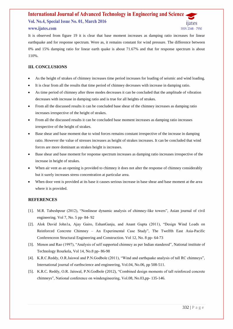
Figure 18 shows damping ratio values versus their base shear in kN of 45m height of strakes for earthquake,
response spectrum and wind forces.
Figure 18 Comparison of base shear for 45m strakes
It is observed from figure 18 it is clear that base shear increases as damping ratio increases for linear earthquake
and for response spectrum. Were as, it remains constant for wind pressure. The difference between 0% and 15%
damping ratio for linear earth quake is about 71.65% and that for response spectrum is about 15.38%.
Figure 19 shows damping ratio values versus their base moment in kN-m of 45m height of strakes for
earthquake, response spectrum and wind forces.
Figure 19 Comparison of base moment for 45m strakes
332 | P a g e
It is observed from figure 19 it is clear that base moment increases as damping ratio increases for linear
earthquake and for response spectrum. Were as, it remains constant for wind pressure. The difference between
0% and 15% damping ratio for linear earth quake is about 71.67% and that for response spectrum is about
110%.
III. CONCLUSIONS
As the height of strakes of chimney increases time period increases for loading of seismic and wind loading.
It is clear from all the results that time period of chimney decreases with increase in damping ratio.
As time period of chimney after three modes decreases it can be concluded that the amplitude of vibration
decreases with increase in damping ratio and is true for all heights of strakes.
From all the discussed results it can be concluded base shear of the chimney increases as damping ratio
increases irrespective of the height of strakes.
From all the discussed results it can be concluded base moment increases as damping ratio increases
irrespective of the height of strakes.
Base shear and base moment due to wind forces remains constant irrespective of the increase in damping
ratio. However the value of stresses increases as height of strakes increases. It can be concluded that wind
forces are more dominant as strakes height is increases.
Base shear and base moment for response spectrum increases as damping ratio increases irrespective of the
increase in height of strakes.
When air vent as an opening is provided to chimney it does not alter the response of chimney considerably
but it surely increases stress concentration at particular area.
When door vent is provided at its base it causes serious increase in base shear and base moment at the area
where it is provided.
REFERENCES
[1]. M.R. Tabeshpour (2012), “Nonlinear dynamic analysis of chimney-like towers”, Asian journal of civil
engineering. Vol 7, No. 5 pp- 84- 92
[2]. Alok David John1a, Ajay Gairo, EshanGanju, and Anant Gupta (2011), “Design Wind Loads on
Reinforced Concrete Chimney – An Experimental Case Study”, The Twelfth East Asia-Pacific
Conferenceon Structural Engineering and Construction. Vol 12, No. 8 pp- 64-73
[3]. Menon and Rao (1997), “Analysis of self supported chimney as per Indian standered”, National institute of
Technology Rourkela, Vol 14, No.8 pp- 86-98
[4]. K.R.C.Reddy, O.R.Jaiswal and P.N.Godbole (2011), “Wind and earthquake analysis of tall RC chimneys”,
International journal of earthscience and engineering, Vol.04, No.06, pp 508-511.
[5]. K.R.C. Reddy, O.R. Jaiswal, P.N.Godbole (2012), “Combined design moments of tall reinforced concrete
chimneys”, National conference on windengineering, Vol.08, No.03,pp- 135-146.
333 | P a g e
[6]. Ingale S. D., Magdum M. M.(2013), “Vibration Control of Uniformly Tapered Chimney by Using Tuned
Mass Damper”, InternationalJournal of Engineering Science and Innovative Technology (IJESIT)Vol 2,
No. 1 pp- 148- 163.
[7]. Chang Han Lee and Habib H. Jabali(2001), “Stresses in Concrete Chimneys Weakened by Openings" ACI
Journal, Title No. 73-38, pp- 465- 468.
[8]. Victor I. Fernandez-Davilla, Rodrigo A. Dunner, and Leonardo E. Carrion (2005), “Simplified Method for
the Seismic Analysis of Industrial Chimneys” ACI Structural Journal, Title no.102-S34, V.102, No. 3,pp-
347-353,.
[9]. Dr V. V. S. RaoNagadi (2005), “The Case of a Tilted Chimney- a Forensic Analysis”
Consultantapvt.ltd.New Delhi, India,Vol 11, No. 6 pp-89-96
[10]. John J. Carty, Jagadish R. Joshi, Randolph W. Snook (1998), “Design and Construction of Reinforced
Concrete Chimneys” (ACI 307-98) reported by ACI Committee 307, 67-73.Vol 13, No. 1 pp- 67-73
[11]. Chen C. H 2005, “Seismic Assessment of a Retrofitted Chimney by FEM Analysis and Field
Testing(1999),” Department of Civil Engineering, National University of Kaohsiung, Taiwan. 45-51,Vol
13, No. 1 pp- 45-51
[12]. Wei Huang, phillip L. Gould (2007), “3-D pushover analysis of a collapsed reinforced concrete chimney”
Finite Elements in Analysis and Design 43Vol 13, No. 1 pp-879-887
[13]. Sami A. Kilic and Mete A. Sozen (2003), “Evaluation of Effect 1999, Marmara Earthquake on Two Tall
Reinforced Concrete Chimneys” ACI Structural Journal, Title No. 100-S39, V. 100 No.(3), pp-357-364,.
[14]. John L. Wilson (2002), “A seismic design of tall reinforced concrete chimneys” ACI Structural Journal
title no. 99-S64, V. 99, No. 5,pp- 622-630,.
[15]. Amir M. Horr, Mohammad Safi, and NaserAsadpour (2004), “Global nonlinear dynamic analysis of
concrete chimneys in frequency domain” ACI Structural Journal, title no. 101-S35, V. 101, No. 3,pp- 341-
350.
[16]. Wadi S. Rumman (1985), “Modal characteristics of linearly tapered reinforced concrete chimneys” ACI
Structural Journal title No. 82-S48, pp-531-536.
[17]. W. S. Rumman (1963),“Modes of vibration of tall concrete chimney with steel lining.” Dissertation
Report, The University of Michigan, Industry program of the college of Engineering. 1-37, Vol 13, No. 1
pp- 97-112.
[18]. Brijesh Kumar Gupta(2003), “Study on Seismic Response of Tall Chimneys” Dissertation report, Indian
Institute Technology Kanpur, pp-20-52.
[19]. IS: 4998(Part-1)1992, “Criteria for Design of Reinforced Concrete Chimneys”, Bureau of Indian Standard,
New Delhi.
[20]. IS 1893 (Part 1):2002, “Indian Standard Criteria for Earthquake Resistant Design of Structures: General
Provisions and Buildings”, Bureau of Indian Standards, New Delhi.