design and analysis of crank shaft - ijpresijpres.com/pdf33/37.pdf · design and analysis of crank...
TRANSCRIPT

INTERNATIONAL JOURNAL OF PROFESSIONAL ENGINEERING STUDIES Volume VIII /Issue 5 / AUG 2017
IJPRES
DESIGN AND ANALYSIS OF CRANK SHAFT
1 MR D. CHANAKYA GUPTA 2 MR CHAITANYA JOSHI. 3 MR B RAMAKRISHNA.
1 Bachelor of technology, Department of Mechanical Engineering, Mahatma Gandhi institute of technology,
Gandipet Main Rd, Kokapet, Hyderabad, Telangana 500075
2 Bachelor of technology, Department of Mechanical Engineering, Mahatma Gandhi institute of technology
Gandipet Main Rd, Kokapet, Hyderabad, Telangana 500075 3 Assistant Professor, Department of Mechanical Engineering, Mahatma Gandhi institute of technology
Gandipet Main Rd, Kokapet, Hyderabad, Telangana 500075
ABSTRACT
A crankshaft related to crank is a mechanical part
able to perform a conversion between reciprocating
motion and rotational motion. In a reciprocating
engine, it translates reciprocating motion of
the piston into rotational motion; whereas in
a reciprocating compressor, it converts the rotational
motion into reciprocating motion. In order to do the
conversion between two motions, the crankshaft has
"crank throws" or "crankpins", additional bearing
surfaces whose axis is offset from that of the crank,
to which the "big ends" of the connecting rods from
each cylinder attach.
Crankshaft is one of the critical components for the
effective and precise working of the internal
combustion engine. In this paper a static simulation is
conducted on a crankshaft from a single cylinder 4-
stroke diesel engine.
In this project a three- dimensional model of diesel
engine crankshaft is created using solid works 2016
design software. Finite element analysis (FEA) is
performed on the crank shaft. The static analysis is
done using Ansys work bench 14.5 software by
applying load and various materials on it and stress
strain deformation will be noted as result due to
applied load on different materials..
Thus the part which is modelled is converted into igs
file to import in ansys work bench and static
structural analysis is carried out at 35 MPA of
pressure load by applying various materials, materials
used in this project are such as aluminum alloy
(which is already existing), 42CrMo4 (Special alloy
steel), magnesium alloy and Al+B4C (aluminium
alloy+ 5% Boron carbide)
1. INTRODUCTION
Fig1. Crank shaft
Crank shaft is a large component with a
complex geometry in the I.C engine, which converts
the reciprocating displacement of the piston to a
rotary motion with a four bar link mechanism.
Crankshaft consisting of shaft parts, two journal
bearings and one crankpin bearing. The Shaft parts
which revolve in the main bearings, the crank pins to
which the big end of the connecting rod are
connected, the crank arms or webs which connect the

INTERNATIONAL JOURNAL OF PROFESSIONAL ENGINEERING STUDIES Volume VIII /Issue 5 / AUG 2017
IJPRES
crank pins and shaft parts. In addition, the linear displacement of an engine is not smooth; as the
displacement is caused by the combustion chamber
therefore the displacement has sudden shocks. The
concept of using crankshaft is to change these sudden
displacements to as smooth rotary output, which is
the input to many devices such as generators, pumps
and compressors. It should also be stated that the use
of a flywheel helps in smoothing the shocks.
1.1 Major Forces Applied On Crank Shaft
Crankshaft experiences large forces from
gas combustion. This force is applied to the top of the
piston and since the connecting rod connects the
piston to the crank shaft, the force will be transmitted
to the crankshaft. The magnitude of the forces
depends on many factors which consist of crank
radius, connecting rod dimensions, weight of the
connecting rod, piston, piston rings, and pin.
Combustion and inertia forces acting on the
crankshaft. 1. Torsional load 2.Bending load.
Crankshaft must be strong enough to take the
downward force of the power stroke without
excessive bending so the reliability and life of the
internal combustion engine depend on the strength of
the crankshaft largely.
The crank pin is like a built in beam with a
distributed load along its length that varies with
crank positions. Each web is like a cantilever beam
subjected to bending and twisting. 1. Bending
moment which causes tensile and compressive
stresses. 2. Twisting moment causes shear stress.
There are many sources of failure in the
engine one of the most common crankshaft failure is
fatigue at the fillet areas due to the bending load
causes by the combustion. The moment of
combustion the load from the piston is transmitted to
the crankpin, causing a large bending moment on the
entire geometry of the crankshaft. At the root of the
fillet areas stress concentrations exist and these high
stress range locations are the points where cyclic
loads could cause fatigue crank initiation leading to
fracture.
1.2 Principle of Crankshaft
A crankshaft is a fundamental feature in a
vehicle’s engine. It is the system that converts linear
energy into rotational energy. This enables the
wheels to drive the car forward. All the pistons in the
engine are attached to the crank which is also
connected to the flywheel. The crank works in
association with other engine components to achieve
a synchronized motion. This process, which enables
the vehicle’s engine to run, is explained below.
1.3 Cylinder Arrangement
The crankshaft is found below the cylinders of a
vehicle’s engine. On V-type engines it is found at the
base but on flat engines it is found between the
cylinder banks. Motor vehicles may have 3 to 12
cylinders inside the engine although most have four.
Inside each cylinder is a piston which moves up and
down the cylinder. All the engine’s pistons are
connected to the crankshaft by individual rods. The
cylinders work in concert as well as with other engine
parts. This is referred to as the four-stroke cycle and
occurs in each of the four cylinders. This cycle is
what drives a vehicle’s engine.
2. FOUR-STROKE CYCLE
The four strokes refer to intake, compression, power
and exhaust. On the intake stroke, the piston starts
down as the intake valve opens to allow air and fuel
into the cylinder. As soon as the piston arrives at the
base of the intake stroke, it triggers closure of the
intake valve. The air-fuel mixture is retained in the
cylinder. This mixture is compressed severely by the
piston as it moves up. The cylinder contents are

INTERNATIONAL JOURNAL OF PROFESSIONAL ENGINEERING STUDIES Volume VIII /Issue 5 / AUG 2017
IJPRES
ignited by the spark plug during which process
expansion occurs. The combustion process lowers the
piston which turns the crank to yield power to drive
the vehicle. The exhaust valve then opens to release
the exhaust once the piston gets to the bottom of the
cylinder.
3. CRANKSHAFT-CAMSHAFT OPERATIONS
The crank moves the pistons up and down inside the
cylinders. The movement of the pistons is regulated
by the crank. A component known as the camshaft
also ensures that the pistons work properly.
Whenever the crank rotates, the camshaft must also
rotate along with it. This is because the two
components are linked together. The two engine parts
have a synchronized movement. When the camshaft
rotates it causes the intake and outtake valves to
open. This allows a flow of air which is important to
cause explosions in the cylinder. Explosions are
created inside the cylinders in the engine. The
explosions exert pressure on the pistons so that they
maintain their movement. These explosions result in
movement of the wheels. The moving pistons give
rise to jerky movements. The flywheel which is
found at the end of the shaft helps to ease the erratic
movement. When the shaft moves, it causes the
flywheel to adopt a circular motion. Notches in the
flywheel help it to achieve a more regular motion.
This motion eventually causes the vehicle’s wheels to
turn since the flywheel is connected to other engine
parts.
4. WORKING OF CRANK SHAFT
Power from the burnt gases in the combustion
chamber is delivered to the crankshaft through the
piston, piston pin and connecting rod. The crankshaft
changes reciprocating motion of the piston in
cylinder to the rotary motion of the flywheel.
Conversion of motion is executed by use of the offset
in the crankshaft. Each offset part of the crankshaft
has a bearing surface known as a crank pin to which
the connecting rod is attached. Crank-through is the
offset from the crankshaft centre line. The stroke of
the piston is controlled by the throw of the
crankshaft. The combustion force is transferred to the
crank-throw after the crankshaft has moved past top
dead centre to produce turning effort or torque, which
rotates the crankshaft. Thus all the engine power is
delivered through the crankshaft. The cam-shaft is
rotated by the crankshaft through gears using chain
driven or belt driven sprockets. The cam-shaft drive
is timed for opening of the valves in relation to the
piston position. The crankshaft rotates in main
bearings, which are split in half for assembly around
the crankshaft main bearing journals.
Both the crankshaft and camshaft must be
capable of withstanding the intermittent variable
loads impressed on them. During transfer of torque to
the output shaft, the force deflects the crankshaft.
This deflection occurs due to bending and twisting of
the crankshaft. Crankshaft deflections are directly
related to engine roughness. When deflections of the
crankshaft occur at same vibrational or resonant
frequency as another engine part, the parts vibrate
together. These vibrations may reach the audible
level producing a “thumping” sound. The part may
fail if this type of vibration is allowed to continue.
Harmful resonant frequencies of the crankshaft are
damped using a torsional vibration damper. Torsional
stiffness is one of the most important crankshaft
design requirements. This can be achieved by using
material with the correct physical properties and by
minimizing stress concentration. The crankshaft is
located in the crankcase and is supported by main
bearings. Figure 3.62 represents schematic view of a
typical crankshaft. The angle of the crankshaft throws

INTERNATIONAL JOURNAL OF PROFESSIONAL ENGINEERING STUDIES Volume VIII /Issue 5 / AUG 2017
IJPRES
in relation to each other is selected to provide a
smooth power output. V-8 engines use 90 degree and
6 cylinder engines use 120 degree crank throws. The
engine firing order is determined from the angles
selected. A crankshaft for a four cylinder engine is
referred to a five bearing shaft. This means that the
shaft has five main bearings, one on each side of
every big end which makes the crankshaft very stiff
and supports it well. As a result the engine is
normally very smooth and long lasting.
Fig 4.1 Parts Attached To Crank Shaft
Fig 4.2 Inline cylinder piston arrangement to crank
shaft
This Figure describes that how a crankshaft is fitted
in a car.Its joining from Cylinders to piston to
crankshaft to itself and then to the wheels of the car.
Because of the additional internal webs required to
support the main bearings, the crank case itself is
very stiff. The disadvantages of this type of bearing
arrangement are that it is more expensive and engine
may have to be slightly longer to accommodate the
extra main bearings. Counter weights are used to
balance static and dynamic forces that occur during
engine operation.Main and rod bearing journal
overlap increases crankshaft strength because more
of the load is carried through the overlap area rather
than through the fillet and crankshaft web. Since the
stress concentration takes place at oil holes drilled
through the crankshaft journals, these are usually
located where the crankshaft loads and stresses are
minimal. Lightening holes in the crank throws do not
reduce their strength if the hole size is less than half
of the bearing journal diameter, rather these holes
often increase crankshaft strength by relieving some
of the crankshaft’s natural stress. Automatic
transmission pressure and clutch release forces tend
to push the crankshaft towards the front of the
engine. Thrust bearings in the engine support this
thrust load as well maintain the crankshaft position.
Thrust bearings may be located on any one of the
main bearing journals. Experience shows that the
bearing lasts much longer when the journal is
polished against the direction of normal rotation than
if polished in the direction of normal rotation. Most
crankshafts balancing is done during manufacture by
drilling holes in the counterweight to lighten them.
Sometimes these holes are drilled after the crankshaft
is installed in the engine.
5. CRANK SHAFT MECHANISM:
A crank is an arm attached at right angles to a
rotating shaft by which reciprocating motion is
imparted to or received from the shaft. It is used to
convert circular motion into reciprocating motion, or
vice versa. The arm may be a bent portion of the
shaft, or a separate arm or disk attached to it.
Attached to the end of the crank by a pivot is a rod,
usually called a connecting rod. The end of the rod
attached to the crank moves in a circular motion,
while the other end is usually constrained to move in
a linear sliding motion.
The term often refers to a human-powered crank
which is used to manually turn an axle, as in
INTERNATIONAL JOURNAL OF PROFESSIONAL ENGINEERING STUDIES Volume VIII /Issue 5 / AUG 2017
IJPRES
a bicycle crank set or a brace and bit drill. In this case
a person's arm or leg serves as the connecting rod,
applying reciprocating force to the crank. There is
usually a bar perpendicular to the other end of the
arm, often with a freely rotatable handle
or pedal attached.
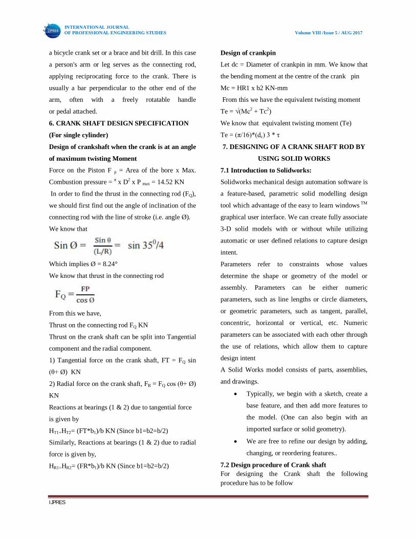
6. CRANK SHAFT DESIGN SPECIFICATION
(For single cylinder)
Design of crankshaft when the crank is at an angle
of maximum twisting Moment Force on the Piston F p = Area of the bore x Max.
Combustion pressure = π x D2 x P max = 14.52 KN
In order to find the thrust in the connecting rod (FQ),
we should first find out the angle of inclination of the
connecting rod with the line of stroke (i.e. angle Ø).
We know that
Which implies Ø = 8.24°
We know that thrust in the connecting rod
From this we have,
Thrust on the connecting rod FQ KN
Thrust on the crank shaft can be split into Tangential
component and the radial component.
1) Tangential force on the crank shaft, FT = FQ sin
(θ+ Ø) KN
2) Radial force on the crank shaft, FR = FQ cos (θ+ Ø)
KN
Reactions at bearings (1 & 2) due to tangential force
is given by
HT1=HT2= (FT*b1)/b KN (Since b1=b2=b/2)
Similarly, Reactions at bearings (1 & 2) due to radial
force is given by,
HR1=HR2= (FR*b1)/b KN (Since b1=b2=b/2)
Design of crankpin
Let dc = Diameter of crankpin in mm. We know that
the bending moment at the centre of the crank pin
Mc = HR1 x b2 KN-mm
From this we have the equivalent twisting moment
Te = √(Mc2 + Tc2)
We know that equivalent twisting moment (Te)
Te = (π/16)*(dc) 3 * τ
7. DESIGNING OF A CRANK SHAFT ROD BY
USING SOLID WORKS 7.1 Introduction to Solidworks:
Solidworks mechanical design automation software is
a feature-based, parametric solid modelling design
tool which advantage of the easy to learn windows TM
graphical user interface. We can create fully associate
3-D solid models with or without while utilizing
automatic or user defined relations to capture design
intent.
Parameters refer to constraints whose values
determine the shape or geometry of the model or
assembly. Parameters can be either numeric
parameters, such as line lengths or circle diameters,
or geometric parameters, such as tangent, parallel,
concentric, horizontal or vertical, etc. Numeric
parameters can be associated with each other through
the use of relations, which allow them to capture
design intent
A Solid Works model consists of parts, assemblies,
and drawings.
Typically, we begin with a sketch, create a
base feature, and then add more features to
the model. (One can also begin with an
imported surface or solid geometry).
We are free to refine our design by adding,
changing, or reordering features..
7.2 Design procedure of Crank shaft For designing the Crank shaft the following procedure has to be follow
INTERNATIONAL JOURNAL OF PROFESSIONAL ENGINEERING STUDIES Volume VIII /Issue 5 / AUG 2017
IJPRES
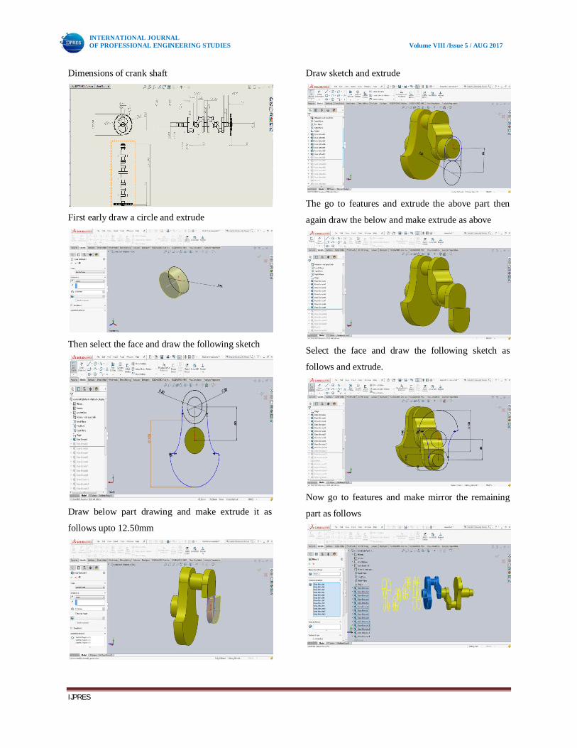
Dimensions of crank shaft
First early draw a circle and extrude
Then select the face and draw the following sketch
Draw below part drawing and make extrude it as
follows upto 12.50mm
Draw sketch and extrude
The go to features and extrude the above part then
again draw the below and make extrude as above
Select the face and draw the following sketch as
follows and extrude.
Now go to features and make mirror the remaining
part as follows

INTERNATIONAL JOURNAL OF PROFESSIONAL ENGINEERING STUDIES Volume VIII /Issue 5 / AUG 2017
IJPRES
Model of crank shaft
Four views of crank shaft
8. ANALYSIS DEFINATION & STEPS:
The steps needed to perform an analysis depend on
the study type. You complete a study by performing
the following steps:
Create a study defining its analysis type and
options.
If needed, define parameters of your study.
A parameter can be a model dimension,
material property, force value, or any other
input.
Define material properties.
Specify restraints and loads.
The program automatically creates a mixed
mesh when different geometries (solid,
shell, structural members etc.) exist in the
model.
Define component contact and contact sets.
Mesh the model to divide the model into
many small pieces called elements. Fatigue
and optimization studies use the meshes in
referenced studies.
Run the study.
View results.
8.1 Analysis on crank shaft by using ansys 14.5
work bench software
The analysis of crank shaft models is carried
out using ANSYS software using Finite Element
Method. Firstly the model files prepare in the
SOLIDWORKS SOFTWARE. Then are exported to ANSYS software as an IGES
files as shown in figure
Fig 8.1 Crank shaft model
8.2 Materials and their properties
8.3 Load & fixed support • Fixed support

INTERNATIONAL JOURNAL OF PROFESSIONAL ENGINEERING STUDIES Volume VIII /Issue 5 / AUG 2017
IJPRES
• Load Load at 35 MPA
8.4 Meshing
Meshing is probably the most important part in any
of the computer simulations, because it can show
drastic changes in results you get. Meshing means
you create a mesh of some grid-points called 'nodes’.
It's done with a variety of tools & options available in
the software. The results are calculated by solving the
relevant governing equations numerically at each of
the nodes of the mesh. The governing equations are
almost always partial differential equations,
and Finite element method is used to find solutions to
such equations. The pattern and relative positioning
of the nodes also affect the solution, the
computational efficiency & time.
Mesh Type: Tetrahedral
No. of nodes: 16722
No. of elements: 8575
9. STRUCTRUAL ANALYSIS RESULTS
9.1 Material: Aluminium Alloy
Maximum Stress
Total Deformation
Maximum Strain
9.2 Material: 42CrMo4 Maximum Stress

INTERNATIONAL JOURNAL OF PROFESSIONAL ENGINEERING STUDIES Volume VIII /Issue 5 / AUG 2017
IJPRES
Total Deformation
Maximum Strain
9.3 Material: Magnesium alloy Maximum Stress
Total Deformation
Maximum Strain
9.4 Material: Al+B4C (Aluminium alloy+5% Boron carbide) Maximum Stress
Total Deformation
Maximum Strain
INTERNATIONAL JOURNAL OF PROFESSIONAL ENGINEERING STUDIES Volume VIII /Issue 5 / AUG 2017
IJPRES
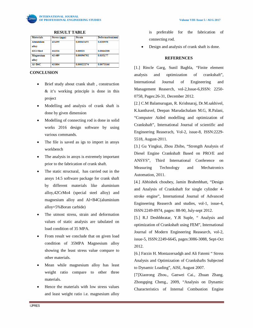
RESULT TABLE
CONCLUSION
Brief study about crank shaft , construction
& it’s working principle is done in this
project
Modelling and analysis of crank shaft is
done by given dimension
Modelling of connecting rod is done in solid
works 2016 design software by using
various commands.
The file is saved as igs to import in ansys
workbench
The analysis in ansys is extremely important
prior to the fabrication of crank shaft.
The static structural, has carried out in the
ansys 14.5 software package for crank shaft
by different materials like aluminium
alloy,42CrMo4 (special steel alloy) and
magnesium alloy and Al+B4C(aluminium
alloy+5%Boran carbide)
The utmost stress, strain and deformation
values of static analysis are tabulated on
load condition of 35 MPA.
From result we conclude that on given load
condition of 35MPA Magnesium alloy
showing the least stress value compare to
other materials.
Mean while magnesium alloy has least
weight ratio compare to other three
materials.
Hence the materials with low stress values
and least weight ratio i.e. magnesium alloy
is preferable for the fabrication of
connecting rod.
Design and analysis of crank shaft is done.
REFERENCES
[1.] Rincle Garg, Sunil Baghla, “Finite element
analysis and optimization of crankshaft”,
International Journal of Engineering and
Management Reaserch, vol-2,Issue-6,ISSN: 2250-
0758, Pages:26-31, December 2012.
[2.] C.M Balamurugan, R. Krishnaraj, Dr.M.sakhivel,
K.kanthavel, Deepan Marudachalam M.G, R.Palani,
“Computer Aided modelling and optimization of
Crankshaft”, International Journal of scientific and
Engineering Reaserach, Vol-2, issue-8, ISSN:2229-
5518, August-2011.
[3.] Gu Yingkui, Zhou Zhibo, “Strength Analysis of
Diesel Engine Crankshaft Based on PRO/E and
ANSYS”, Third International Conference on
Measuring Technology and Mechatronics
Automation, 2011.
[4.] Abhishek choubey, Jamin Brahmbhatt, “Design
and Analysis of Crankshaft for single cylinder 4-
stroke engine”, International Journal of Advanced
Engineering Reaserch and studies, vol-1, issue-4,
ISSN:2249-8974, pages: 88-90, July-sept 2012.
[5.] R.J Deshbhratar, Y.R Suple, “ Analysis and
optimization of Crankshaft using FEM”, International
Journal of Modern Engineering Reasearch, vol-2,
issue-5, ISSN:2249-6645, pages:3086-3088, Sept-Oct
2012.
[6.] Farzin H. Montazersadgh and Ali Fatemi “ Stress
Analysis and Optimization of Crankshafts Subjected
to Dynamic Loading”, AISI, August 2007.
[7]Xiaorong Zhou., Ganwei Cai., Zhuan Zhang.
Zhongqing Cheng., 2009, “Analysis on Dynamic
Characteristics of Internal Combustion Engine

INTERNATIONAL JOURNAL OF PROFESSIONAL ENGINEERING STUDIES Volume VIII /Issue 5 / AUG 2017
IJPRES
Crankshaft System,” International Conference on
Measuring Technology and Mechatronics
Automation.
[8]. Farzin H. Montazersadgh and Ali Fatemi.,
2007,“Dynamic Load and Stress Analysis of a
Crankshaft,” SAE Technical Paper No. 010258,
Society of Automotive Engineers
[9]. Jonathan Williams, Farzin Montazersadgh, and
Alifatemi.,2007, “FatiguePerformance
Comparison And Life Prediction Of Forged Steel
And Ductile Cast Iron Crankshafts,” Published
in Proceeding of the 27th Forging Industry Technical
Conference in Ft.Worth,Texas
[10]. Shenoy, P. S. and Fatemi, A., 2006, “Dynamic
analysis of loads and stresses in connecting
rods,”IMechE, Journal of Mechanical Engineering
Science, Vol. 220, No. 5, pp. 615- 624
[11]. Zoroufi, M. and Fatemi, A.,2005, "A Literature
Review on Durability Evaluation of Crankshafts
Including Comparisons of Competing Manufacturing
Processes and Cost Analysis", 26th Forging Industry
Technical Conference, Chicago, [12]. Prakash, V., Aprameyan, K., and Shrinivasa,
U.,1998, “An FEM Based Approach to Crankshaft
Dynamics and Life Estimation,” SAE Technical
Paper No. 980565, Society of Automotive Engineers
[13]. Payar, E., Kainz, A., and Fiedler, G. A.,
1995,“Fatigue Analysis of Crankshafts Using
Nonlinear Transient Simulation Techniques,” SAE
Technical Paper No. 950709, Society of Automotive
Engineers
[14]. Guagliano, M., Terranova, A., and Vergani, L.,
1993,“Theoretical and Experimental Study of the
Stress Concentration Factor in Diesel Engine
Crankshafts, “Journal of Mechanical Design, Vol.
115, pp. 47-52
[15]. Henry, J., Topolsky, J., and Abramczuk, M.,
1992,“Crankshaft Durability Prediction – A New 3-D
Approach,” SAE Technical Paper No. 920087,
Society of Automotive Engineers
[16]. Stephens, R. I., Fatemi, A., Stephens, R. R., and
Fuchs, H. O., 2001, “Metal Fatigue in
Engineering,”2nd edition, John Wiley and Sons, New
York, NY,USA co.
AUTHERS: MR D. CHANAKYA GUPTA.
Bachelor of technology, Department of Mechanical
Engineering, Mahatma Gandhi institute of
technology, Gandipet Main Rd, Kokapet, Hyderabad,
Telangana 500075
Mobile: +918977686444
E.mail:[email protected]
MR CHAITANYA JOSHI.
Bachelor of technology, Department of Mechanical
Engineering, Mahatma Gandhi institute of
technology
Gandipet Main Rd, Kokapet, Hyderabad, Telangana
500075
Mobile: +918897562324
E.mail:[email protected]
MR B. RAMAKRISHNA.
Assistant Professor, Department of Mechanical
Engineering, Mahatma Gandhi institute of
technology, Gandipet Main Rd, Kokapet, Hyderabad,
Telangana 500075
Mobile: +919985123955