geometric optimization and manufacturing process of six cylinder diesel engine crank shaft used in...
TRANSCRIPT

108
International Journal of Research and Innovation (IJRI)
International Journal of Research and Innovation (IJRI)GEOMETRIC OPTIMIZATION AND MANUFACTURING PROCESS OF SIX CYLINDER
DIESEL ENGINE CRANK SHAFT USED IN AUTOMOBILE USING FEA
Karnati Sreedhar 1,Gandhi Perumallapalli2, D.sreeramprasad 3
1 Research Scholar, Department Of Mechanical Engineering, Sri Venkateswara Engineering College, Amaravadi Nagar, Suryapet,India2 Assistant professor , Department Of Mechanical Engineering, Sri Venkateswara Engineering College, Amaravadi Nagar, Suryapet,India3 Associate Professor , Department Of Mechanical Engineering, Sri Venkateswara Engineering College, Amaravadi Nagar, Suryapet,India
*Corresponding Author:
Karnati Sreedhar, Research Scholar, Department Of Mechanical Engineering, Sri Venkateswara Engineering College,Amaravadi Nagar, Suryapet,IndiaPublished: May 20, 2015Review Type: peer reviewedVolume: II, Issue : II
Citation: Karnati Sreedhar, Research Scholar (2015) GEOMETRIC OPTIMIZATION AND MANUFACTURING PROCESS OF SIX CYLINDER DIESEL ENGINE CRANK SHAFT USED IN AUTOMOBILE USING FEA
Problem Description
When observing 6 cylinder automobiles like busses having frequent break downs due to engine failures. Millage is also become one of the most important thing in those days if we can reduce the mechanical efficiency.
Commonly crank shafts are made with low carbon steels and casting along with milling is used to the produce object.It causes low production rate and high cost.
Methodology
This is an attempt to reduce weight, improve life time and to improve production rate by implement-ing geometric optimization we can reduce failure and by introducing new materials we can reduce weight as well as we switch manufacturing process.By implementing metal injection system we can im-prove production rate.
Introduction
The crankshaft, sometimes casually abbreviated to crank, is the part of an engine which translates reciprocating linear piston motion into rotation. To convert the reciprocating motion into rotation, the crankshaft has "crank throws" or "crankpins", ad-ditional bearing surfaces whose axis is offset from that of the crank, to which the "big ends" of the con-necting rods from each cylinder attach.
It typically connects to a flywheel, to reduce the pul-sation characteristic of the four-stroke cycle, and sometimes a torsional or vibrational damper at the opposite end, to reduce the torsion vibrations often caused along the length of the crankshaft by the cylinders farthest from the output end acting on the torsional elasticity of the metal.
Stress on crankshafts
The shaft is subjected to various forces but gener-ally needs to be analysed in two positions. Firstly, failure may occur at the position of maximum bend-ing; this may be at the centre of the crank or at either end. In such a condition the failure is due to bending and the pressure in the cylinder is maxi-mal. Second, the crank may fail due to twisting, so the conrod needs to be checked for shear at the po-sition of maximal twisting. The pressure at this po-sition is the maximal pressure, but only a fraction of maximal pressure.
A crankshaft contains two or more centrally-located coaxial cylindrical ("main") journals and one or more offset cylindrical crankpin ("rod") journals. The two-
Abstract
The crankshaft is that part of an engine which translates reciprocating linear piston motion into rotation. To convert the reciprocating motion into rotation, the crankshaft has "crank" or "crankpins", additional bearing surfaces whose axis is offset from that of the crank, to which the "big ends" of the connecting rods from each cylinder attach.The aim of the project work is to optimize the geometry shape of 6-cylinder diesel engine crank shaft to reduce the fail-ures and to reduce the weight. And also this project work will provide the brief explanation of manufacturing process.Initially literature survey and data collection will be done to understand methodology.Design calculations will be done to get parameters of object for drafting.3D model will be prepared according to the obtained parameters.Analysis will be conducted on crank shaft to rectify failures by optimizing geometric shape. Also best material will be suggested by analyzing and comparing results with the variation of materials.Mold tool design will be done and assembly will be prepared according to that.Cnc program will be prepared for die set using cam
1401-1402
109
International Journal of Research and Innovation (IJRI)
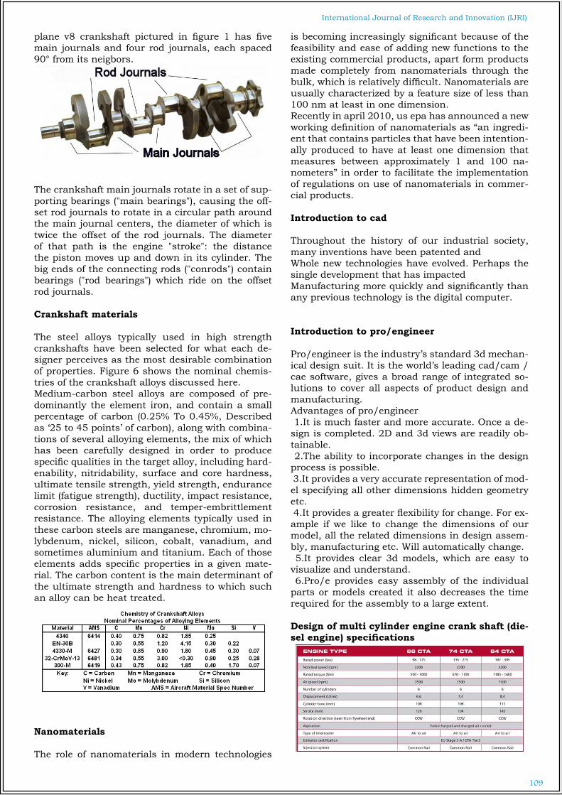
plane v8 crankshaft pictured in figure 1 has five main journals and four rod journals, each spaced 90° from its neigbors.
The crankshaft main journals rotate in a set of sup-porting bearings ("main bearings"), causing the off-set rod journals to rotate in a circular path around the main journal centers, the diameter of which is twice the offset of the rod journals. The diameter of that path is the engine "stroke": the distance the piston moves up and down in its cylinder. The big ends of the connecting rods ("conrods") contain bearings ("rod bearings") which ride on the offset rod journals.
Crankshaft materials
The steel alloys typically used in high strength crankshafts have been selected for what each de-signer perceives as the most desirable combination of properties. Figure 6 shows the nominal chemis-tries of the crankshaft alloys discussed here.Medium-carbon steel alloys are composed of pre-dominantly the element iron, and contain a small percentage of carbon (0.25% To 0.45%, Described as ‘25 to 45 points’ of carbon), along with combina-tions of several alloying elements, the mix of which has been carefully designed in order to produce specific qualities in the target alloy, including hard-enability, nitridability, surface and core hardness, ultimate tensile strength, yield strength, endurance limit (fatigue strength), ductility, impact resistance, corrosion resistance, and temper-embrittlement resistance. The alloying elements typically used in these carbon steels are manganese, chromium, mo-lybdenum, nickel, silicon, cobalt, vanadium, and sometimes aluminium and titanium. Each of those elements adds specific properties in a given mate-rial. The carbon content is the main determinant of the ultimate strength and hardness to which such an alloy can be heat treated.
Nanomaterials
The role of nanomaterials in modern technologies
is becoming increasingly significant because of the feasibility and ease of adding new functions to the existing commercial products, apart form products made completely from nanomaterials through the bulk, which is relatively difficult. Nanomaterials are usually characterized by a feature size of less than 100 nm at least in one dimension. Recently in april 2010, us epa has announced a new working definition of nanomaterials as “an ingredi-ent that contains particles that have been intention-ally produced to have at least one dimension that measures between approximately 1 and 100 na-nometers” in order to facilitate the implementation of regulations on use of nanomaterials in commer-cial products.
Introduction to cad
Throughout the history of our industrial society, many inventions have been patented andWhole new technologies have evolved. Perhaps the single development that has impactedManufacturing more quickly and significantly than any previous technology is the digital computer.
Introduction to pro/engineer
Pro/engineer is the industry’s standard 3d mechan-ical design suit. It is the world’s leading cad/cam /cae software, gives a broad range of integrated so-lutions to cover all aspects of product design and manufacturing. Advantages of pro/engineer 1.It is much faster and more accurate. Once a de-sign is completed. 2D and 3d views are readily ob-tainable. 2.The ability to incorporate changes in the design process is possible. 3.It provides a very accurate representation of mod-el specifying all other dimensions hidden geometry etc. 4.It provides a greater flexibility for change. For ex-ample if we like to change the dimensions of our model, all the related dimensions in design assem-bly, manufacturing etc. Will automatically change. 5.It provides clear 3d models, which are easy to visualize and understand. 6.Pro/e provides easy assembly of the individual parts or models created it also decreases the time required for the assembly to a large extent.
Design of multi cylinder engine crank shaft (die-sel engine) specifications

110
International Journal of Research and Innovation (IJRI)
Pressure calculationsEngine type: air cooled 4-stroke (Agco sisu power 66cta bus)Number of cylinders =6Bore diameter (d) = 108 mmStroke length (l) = 120mmMaximum combustion pressure=10.466N/mm2
Displacement =6600ccCompression ratio =23:1Density of diesel = 874.6081Kg/m3 at 15°cT =288.855KMass = density ×volume = 0.0000008746081×6600000 = 5.77KgMolecular weight for diesel is 200 g/molePv = mrt
We know that force on the piston i, e: gas load
In order to find the thrust in connecting rod we should find out angle of inclination of connecting rod with line of stroke (i,e: angle ) (lies between 30° to 40°)
Assume that the distance (b) between the bearings 1 and 2 is equal to twice the piston diameter (d). B = 2d = 2 × 108 =216mm Due to this piston gas load (fp) acting horizontally, there will be two horizontal reactions h1and h2 at bearings 1 and 2 respectively, such that B1 = b2= 108mm
Assume that the length of the main bearings to be equal, i.E., C1 = c2 = c / 2. We know that due to the weight of the flywheel acting downwards, there will be two vertical reac-tions v2 and v3 at bearings 2 and 3 respectively, such that
Model of crank shaft
The above image shows total sections
2D drafting crankshaft
Powder metallurgy
Powder metallurgy is a forming and fabrication technique consisting of three major processing stag-es. First, the primary material is physically pow-dered, divided into many small individual particles. Next, the powder is injected into a mold or passed through a die to produce a weakly cohesive struc-ture (via cold welding) very near the dimensions of the object ultimately to be manufactured. Pressures of 10-50 tons per square inch are commonly used. Also, to attain the same compression ratio across more complex pieces, it is often necessary to use lower punches as well as an upper punch. Finally, the end part is formed by applying pressure, high temperature, long setting times (during which self-

111
International Journal of Research and Innovation (IJRI)
welding occurs), or any combination thereof.Cad/cam in die design
In the die casting scenario the advent of digital com-puters has facilitated the improvement of productiv-ity and elimination of costly rework. Here before the physical realization of the die, the design can be redefined and the parameters can be decided which would yield good results. Variety of feed systems and combination of ideas can be selected. This is an analytic approach to estimate the validity of the design. Thus it gives enormous confidence to the designer even before the tool is manufactured.
Core & cavity design with pro/engineerCore cavity preparation
Create parting surface
Create work piece
The above image shows cavity 1
The above image shows total die assembly
The above image shows exploded view of complete die
Introduction to manufacturing
The manufacturing of various products is done at different scales ranging from humble domestic pro-duction of say candlesticks to the manufacturing of huge machines including ships, aeroplanes and so forth. The word manufacturing technology is mainly used for the latter range of the spectrum of manu-facturing, and refers to the commercial industrial production of goods for sale and consumption with the help of gadgets and advanced machine tools. Industrial production lines involve changing the shape, form and/or composition of the initial prod-ucts known as raw materials into products fit for final use known as finished products.
Procedure of manufacturing
CavityRoughing
With workpiece

112
International Journal of Research and Innovation (IJRI)
Cutting tool
Playpath
Vericut
Roughing program%G71O0001(\Roughing.Ncl.1)(04/30/15-12:13:46)N0010t1m06S1500m03G01g43x-377.072Y-157.018Z2.F500.H01m08Z-2.F150.
Introduction to fea
Finite element analysis (fea) was first developed in 1943 by r. Courant, who utilized the ritz method of numerical analysis and minimization of variational calculus to obtain approximate solutions to vibra-tion systems. Shortly thereafter, a paper published in 1956 by m. J. Turner, r. W. Clough, h. C. Mar-tin, and l. J. Topp established a broader definition of numerical analysis. The paper centered on the "stiffness and deflection of complex structures".
By the early 70's, fea was limited to expensive main-frame computers generally owned by the aeronaut-ics, automotive, defense, and nuclear industries. Since the rapid decline in the cost of computers and the phenomenal increase in computing power, fea has been developed to an incredible precision. Pre-sent day supercomputers are now able to produce accurate results for all kinds of parameters.Fea consists of a computer model of a material or design that is stressed and analyzed for specific re-sults. It is used in new product design, and existing product refinement. A company is able to verify a proposed design will be able to perform to the cli-ent's specifications prior to manufacturing or con-struction. Modifying an existing product or struc-ture is utilized to qualify the product or structure for a new service condition.In case of structural fail-ure, fea may be used to help determine the design modifications to meet the new condition.
Introduction to ansys
Ansys is general-purpose finite element analysis (fea) software package. Finite element analysis is a numerical method of deconstructing a complex system into very small pieces (of user-designated size) called elements. The software implements equations that govern the behaviour of these ele-ments and solves them all; creating a comprehen-sive explanation of how the system acts as a whole. These results then can be presented in tabulated, or graphical forms. This type of analysis is typically used for the design and optimization of a system far too complex to analyze by hand. Systems that may fit into this category are too complex due to their geometry, scale, or governing equations.
Material properties and boundary Conditions
Material properties :carbon steel

113
International Journal of Research and Innovation (IJRI)
Boundary conditions
Constrained at crankshaft both endsPressure on shaft
Structural analysis of crankshaft Existing model
Material: carbon steel
The above image shows total deformation
The above image shows stress
The above image shows strain
Dynamic analysis of crankshaft Existing model
The above image shows total deformation mode 1
The above image shows total deformation mode 2
Fatigue analysis of crankshaft existing model
The above image shows life

114
International Journal of Research and Innovation (IJRI)
The above image shows safety factor
The above image shows biaxiality indication
Structural analysis of crankshaft Existing model
Material: nano material
The above image shows total deformation
The above image shows stress
The above image shows strain
Dynamic analysis of crankshaft Existing model
The above image shows total deformation mode 1

115
International Journal of Research and Innovation (IJRI)
The above image shows total deformation mode 2
Fatigue analysis of crankshaft existing model
The above image shows life
The above image shows safety factor
Modified model
2D drafting
Structural analysis of crankshaft Modified modelMaterial: carbon steel
The above image shows total deformation
The above image shows stress

116
International Journal of Research and Innovation (IJRI)
The above image shows strain
Results and graphs
Structural analysis
The above image shows total deformation graph
The above image shows stress graph
The above image shows strain graph
Fatigue analysis
The above image shows safety factor
Results Table
STRUCTURAL ANALYSISExisting model Modified model
carbon steel
Nano material
carbon steel
Nano material
Total de-formation
0.00679 0.012065 0.0059 0.0104887
Stress 12.626 12.348 10.955 10.711
Strain 5.9963e-5 0.000106 5.1513e-5 9.1435e-5
Dynamic analysisExisting model Modified model
carbon steel
Nano material
carbon steel
Nano material
Total defor-mation mode 1HZ
65.455 54.36 66.017 54.827
Total defor-mation mode 2 HZ
67.961 56.441 68.569 56.946
Total defor-mation mode 3 HZ
179.08 148.73 180.71 150.08
Total defor-mation mode 4 HZ
187.09 155.38 188.54 156.58
Total defor-mation mode 5 HZ
248.42 206.31 254.31 211.2
FATIGUE ANALYSISExisting model Modified model
carbon steel
Nano material
carbon steel
Nano material
LIFE 1e6 1e6 1e6 1e6
Damage 1000 1000 1000 1000
Safety factor
3.416 3.4903 3.9344 4.0238
Biaxiality indication
0.99856 0.99856 0.99907 0.99907
Alternat-ing stress
25.252 24.697 21.909 21.422

117
International Journal of Research and Innovation (IJRI)
Conclusion
This project works deals with “geometric optimiza-tion and manufacturing process of six cylinder die-sel engine crank shaft used in automobile using fea”Initially literature survey and data collection was done to understand methodology.Crank shaft parameters are calculated using em-pirical formals for 6 cylinder engine.3D model is prepared according to the obtained valve from calculation,Static, fatigue and dynamic analysis is done on crankshaft using low carbon steel (existing).Same as been done using steel nano material and to find out the failure locations and to evaluate results for new material.Geometric modifications are done on crank shaft model to reduce stress concentration by implement-ing stress reliving holes on web.As per the static, fatigue and dynamic analysis re-sults, existing model is up to the mark only. Im-plementation of nano material will increase life by 2%, while appling stress reliving holes, life will be increased by 17.8% And also weight can be reduced by 22%due to low density for nano steel alloy. Also material is removed from the crank web. So better to use modified model with nano material.In the next step manufacturing is described and for the nano materials better to go with metal injection process.Mould parts are prepared and assembly, which con-tains ejectors, retainers, spacer housing and pins.Cnc codes are generated using cam in pro/engineer.This project concludes that modified model with nano material increases the life and also weight will be reduced up to 35% which interns increases the mechanical efficiency. Metal injection process is the most efficient way to manufacture crankshaft with nano material and also it increase the production rate
References
1.Dynamic stress analysis of a multi cylinder two-stage compres-sor crankshaft Research journal of engineering sciences
2.Design and analysis of crankshaft for single cylinder 4-stroke deisel engine Crankshaft design and optimization- a reviewNational conference on recent trends in engineering & technology
3.Theoretical and experimental analysis of torsional and bend-ing effect on four cylinders engine crankshafts by using finite element approach International journal of engineering research
4.Fatigue strength and residual stress analysis of deep rolled crankshafts International journal of engineering and technology (ijet)
5.Finite element analysis of 4-cylinder diesel crankshaft
6.Crankshaft strength analysis using finite element method International journal of engineering research
7.Concept and manufacture of a crankshaft production tool
8.Elastic multi body simulation of a multi-cylinder engineThe open mechanical engineering journal,
Authour
Karnati sreedhar Research scholar, department of mechanical engineering,sri venkateswara engineering college, Amaravadi nagar, suryapet - 508213.Nalgonada (dt), india.
Gandhi perumallapalliAssistant professor in mechanical engineeringSri venkateswara engineering college, Amaravadi nagar, suryapet - 508213.Nalgonada (dt),india.
D.SreeramprasadAssociate professor in mechanical engineeringSri venkateswara engineering college, 8 Years industrial, 18 years teaching+ years