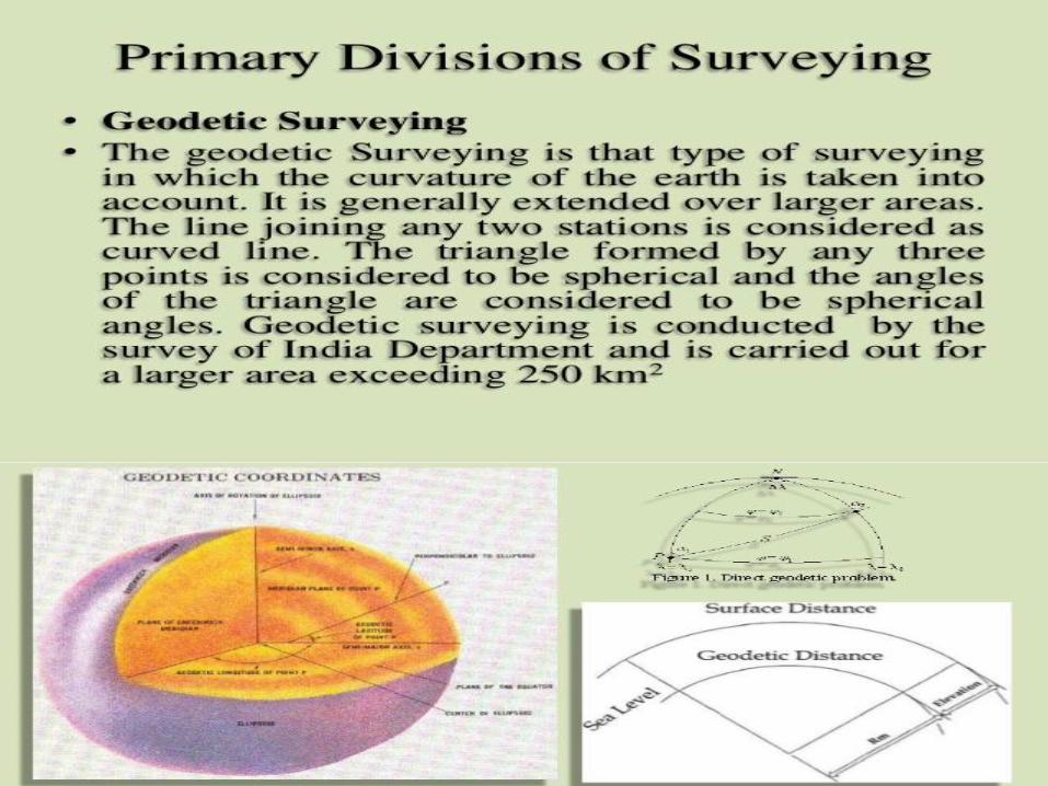
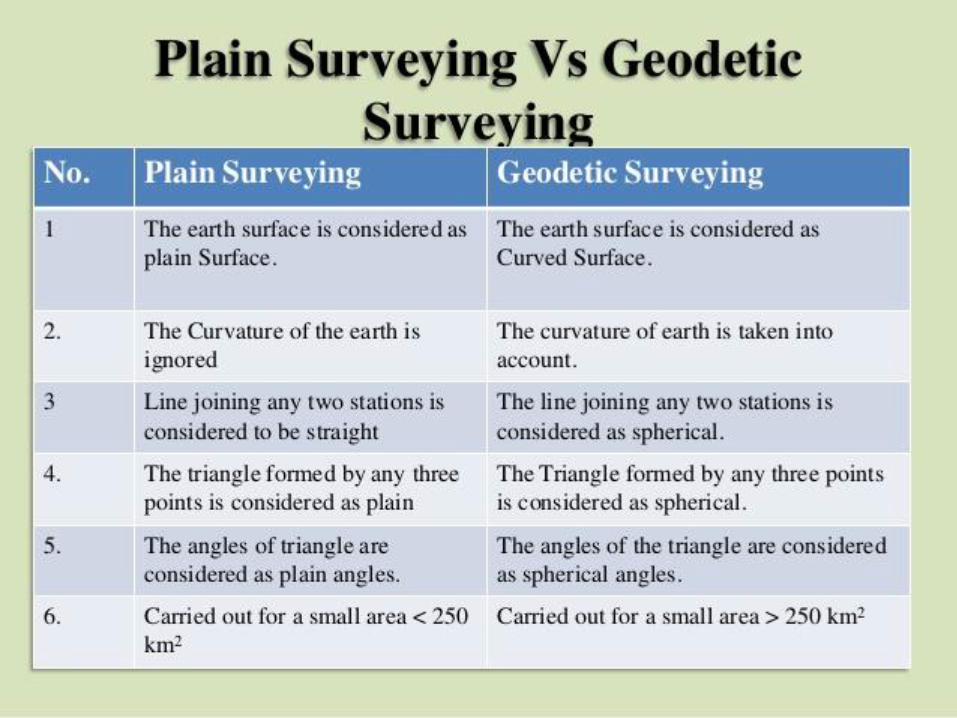
department of civil engineering surveying ... ppt.pdfcheck levelling:-this kind of levelling is...
TRANSCRIPT
DEPARTMENT OF CIVIL ENGINEERING
SURVEYING
COURSE LECTURER
B SURESH
Assistant Professor
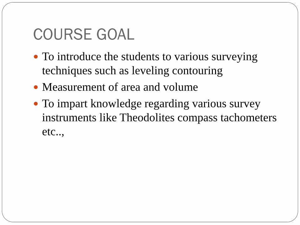
COURSE GOAL
To introduce the students to various surveying
techniques such as leveling contouring
Measurement of area and volume
To impart knowledge regarding various survey
instruments like Theodolites compass tachometers
etc..,
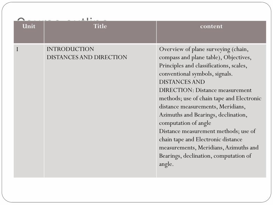
Course outline Unit Title content
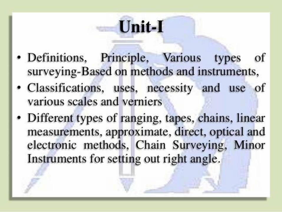
I INTRODUCTION
DISTANCES AND DIRECTION
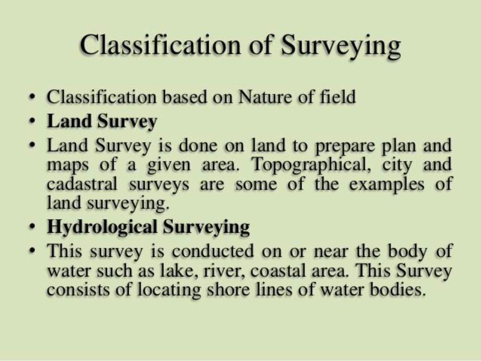
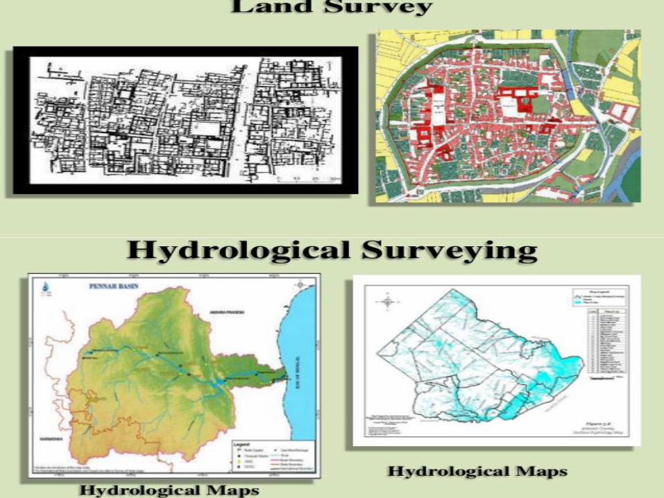
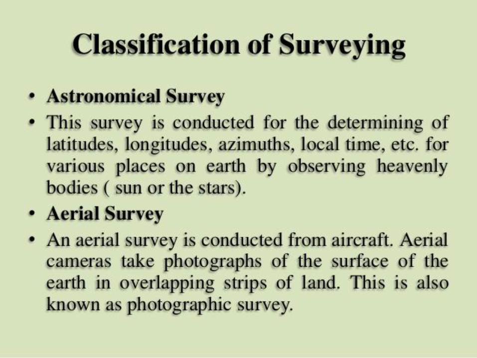
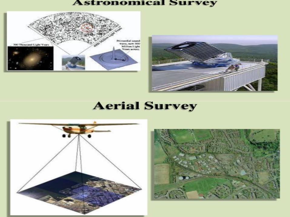
Overview of plane surveying (chain,
compass and plane table), Objectives,
Principles and classifications, scales,
conventional symbols, signals.
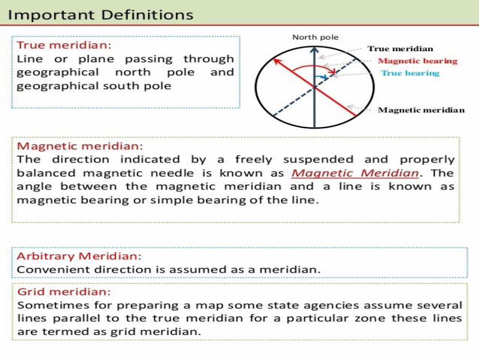
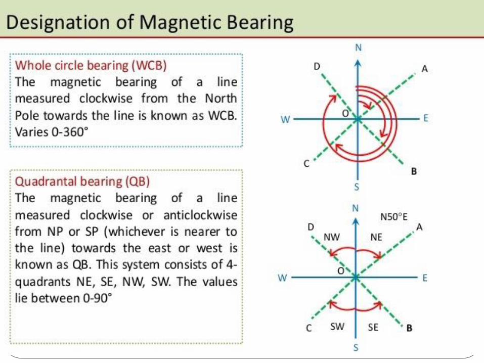
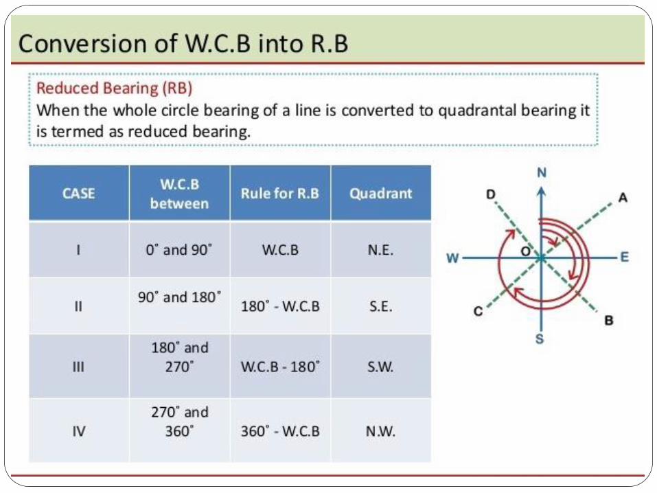
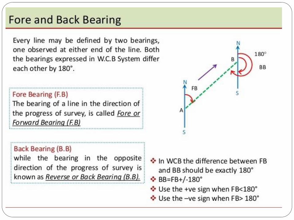
DISTANCES AND
DIRECTION: Distance measurement
methods; use of chain tape and Electronic
distance measurements, Meridians,
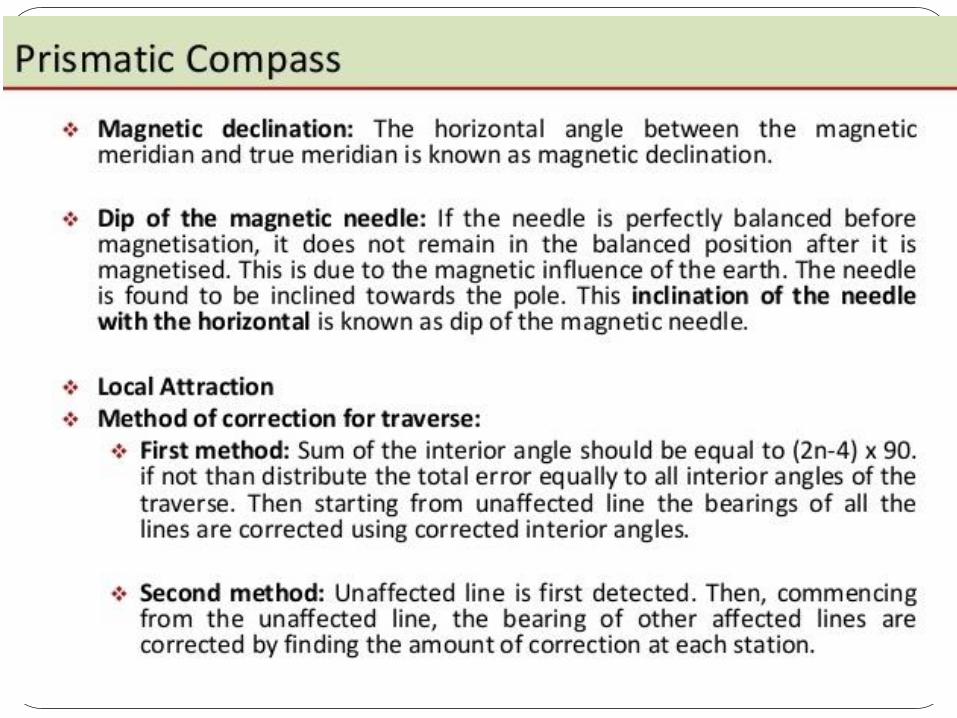
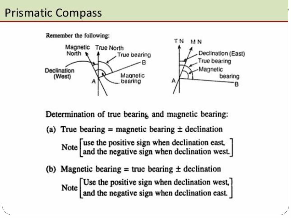
Azimuths and Bearings, declination,
computation of angle
Distance measurement methods; use of
chain tape and Electronic distance
measurements, Meridians, Azimuths and
Bearings, declination, computation of
angle.
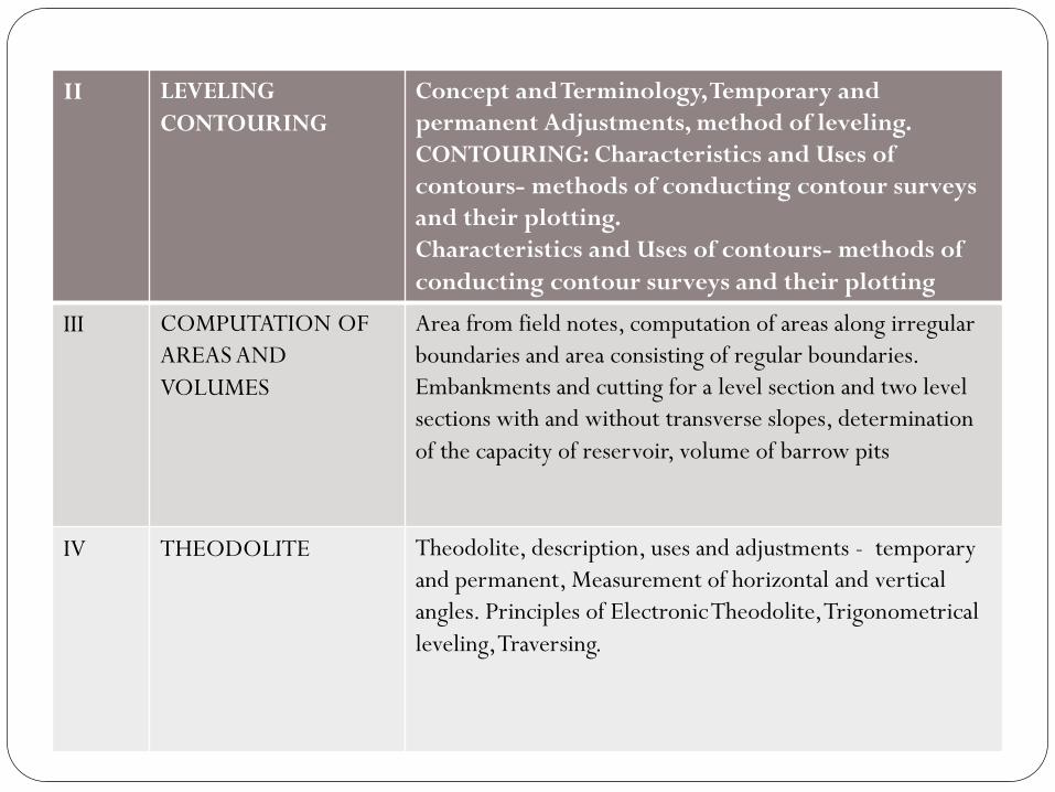
II LEVELING
CONTOURING
Concept and Terminology, Temporary and
permanent Adjustments, method of leveling.
CONTOURING: Characteristics and Uses of
contours- methods of conducting contour surveys
and their plotting.
Characteristics and Uses of contours- methods of
conducting contour surveys and their plotting
III COMPUTATION OF
AREAS AND
VOLUMES
Area from field notes, computation of areas along irregular
boundaries and area consisting of regular boundaries.
Embankments and cutting for a level section and two level
sections with and without transverse slopes, determination
of the capacity of reservoir, volume of barrow pits
IV THEODOLITE Theodolite, description, uses and adjustments - temporary
and permanent, Measurement of horizontal and vertical
angles. Principles of Electronic Theodolite, Trigonometrical
leveling, Traversing.
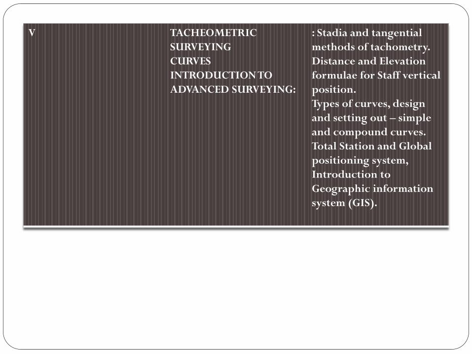
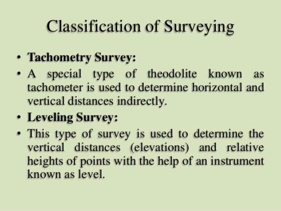
V TACHEOMETRIC
SURVEYING
CURVES
INTRODUCTION TO
ADVANCED SURVEYING:
: Stadia and tangential
methods of tachometry.
Distance and Elevation
formulae for Staff vertical
position.
Types of curves, design
and setting out – simple
and compound curves.
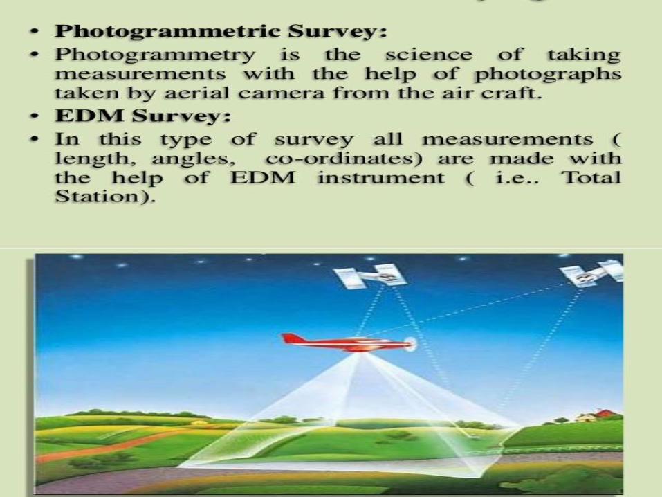
Total Station and Global
positioning system,
Introduction to
Geographic information
system (GIS).

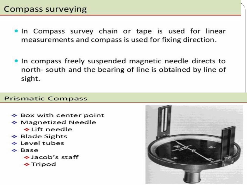
Levelling & Contouring
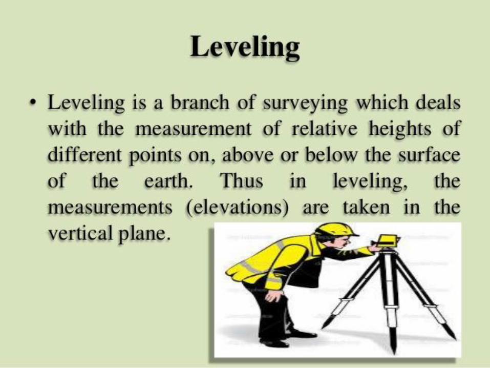
Definition, Principle, & Object of Levelling
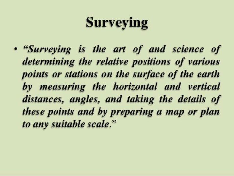
Definition:- Levelling is defined as “an art of
determining the relative height of different
points on, above or below the surface”.
Principle of levelling Principle:- The principle of levelling is to obtain
horizontal line of sight with respect to which
vertical distances of the points above or below this
line of sight are found.
Object of levelling
The objective of levelling is to
1) Find the elevation of given point with
respect to some assumed reference line called
datum.
2)To establish point at required elevation
with respect to datum.
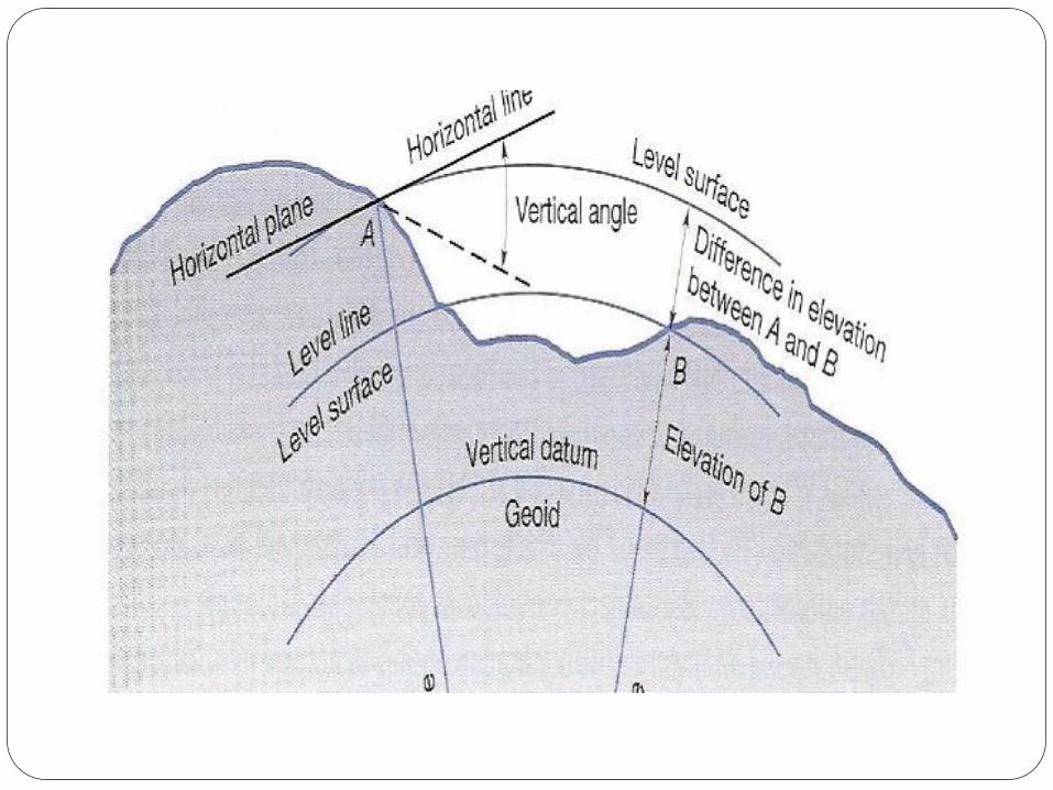
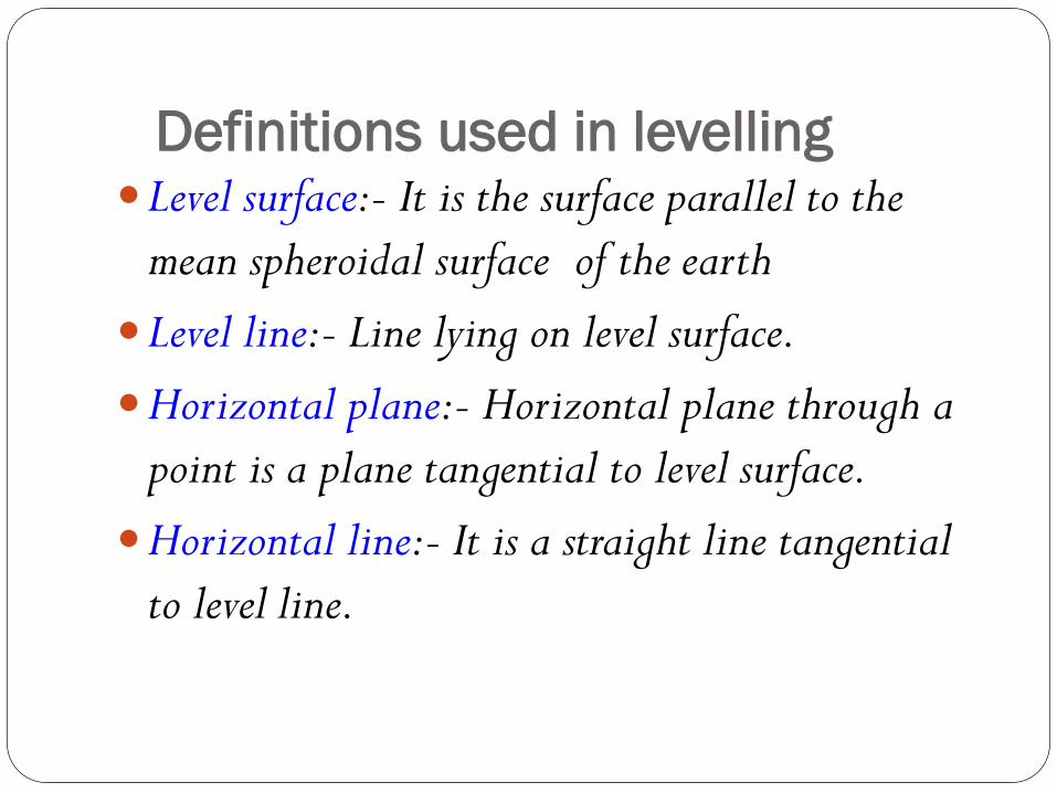
Definitions used in levelling Level surface:- It is the surface parallel to the
mean spheroidal surface of the earth
Level line:- Line lying on level surface.
Horizontal plane:- Horizontal plane through a
point is a plane tangential to level surface.
Horizontal line:- It is a straight line tangential
to level line.
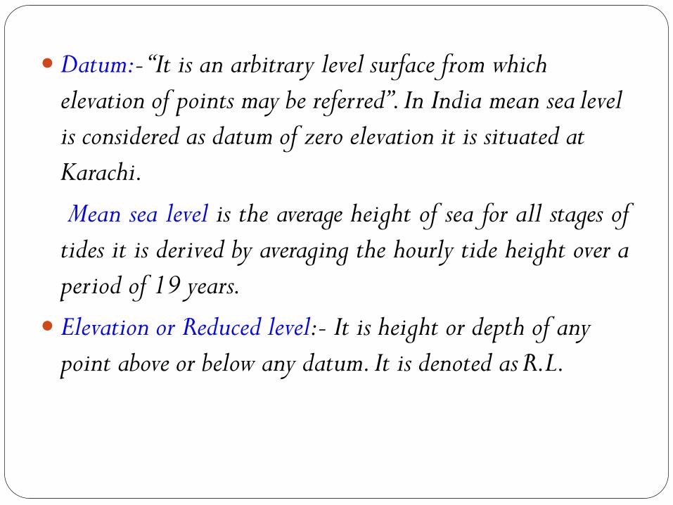
Datum:- “It is an arbitrary level surface from which
elevation of points may be referred”. In India mean sea level
is considered as datum of zero elevation it is situated at
Karachi.
Mean sea level is the average height of sea for all stages of
tides it is derived by averaging the hourly tide height over a
period of 19 years.
Elevation or Reduced level:- It is height or depth of any
point above or below any datum. It is denoted as R.L.
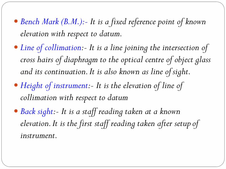
Bench Mark (B.M.):- It is a fixed reference point of known
elevation with respect to datum.
Line of collimation:- It is a line joining the intersection of
cross hairs of diaphragm to the optical centre of object glass
and its continuation. It is also known as line of sight.
Height of instrument:- It is the elevation of line of
collimation with respect to datum
Back sight:- It is a staff reading taken at a known
elevation. It is the first staff reading taken after setup of
instrument.
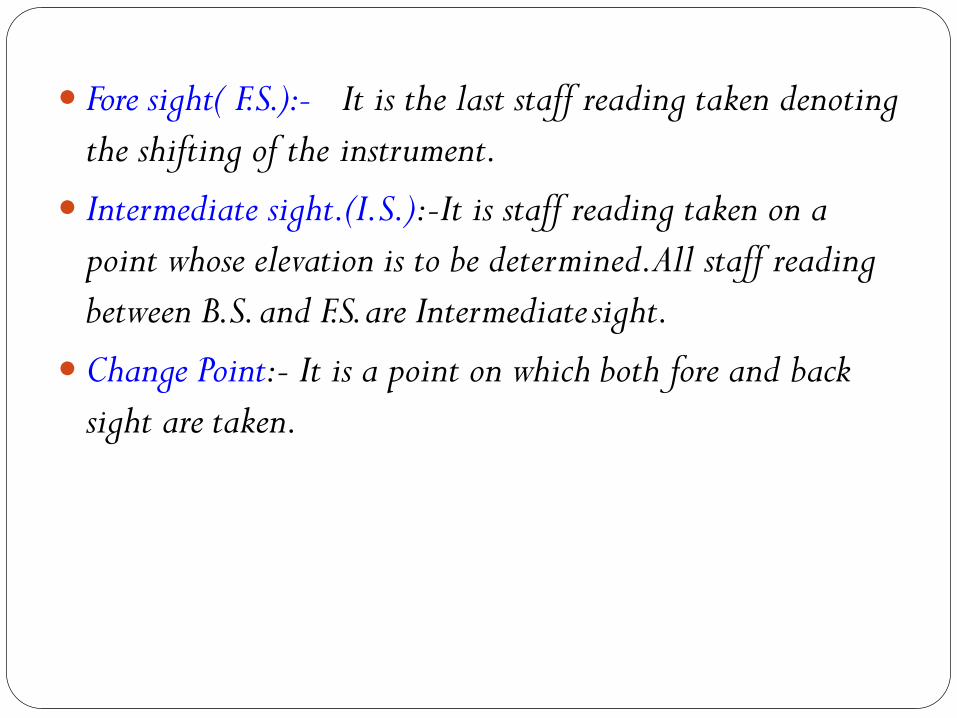
Fore sight( F.S.):- It is the last staff reading taken denoting
the shifting of the instrument.
Intermediate sight.(I.S.):-It is staff reading taken on a
point whose elevation is to be determined.All staff reading
between B.S. and F.S. are Intermediate sight.
Change Point:- It is a point on which both fore and back
sight are taken.
Instruments for levellingThe following instruments are essentially
required
for levelling
Level
Levelling staff
Level and types of level Level:-The instrument used to furnish horizontal line
of sight for observing staff readings and determining
R.L.s
Types
Dumpy level
Tilting level
Wye level
Automatic level
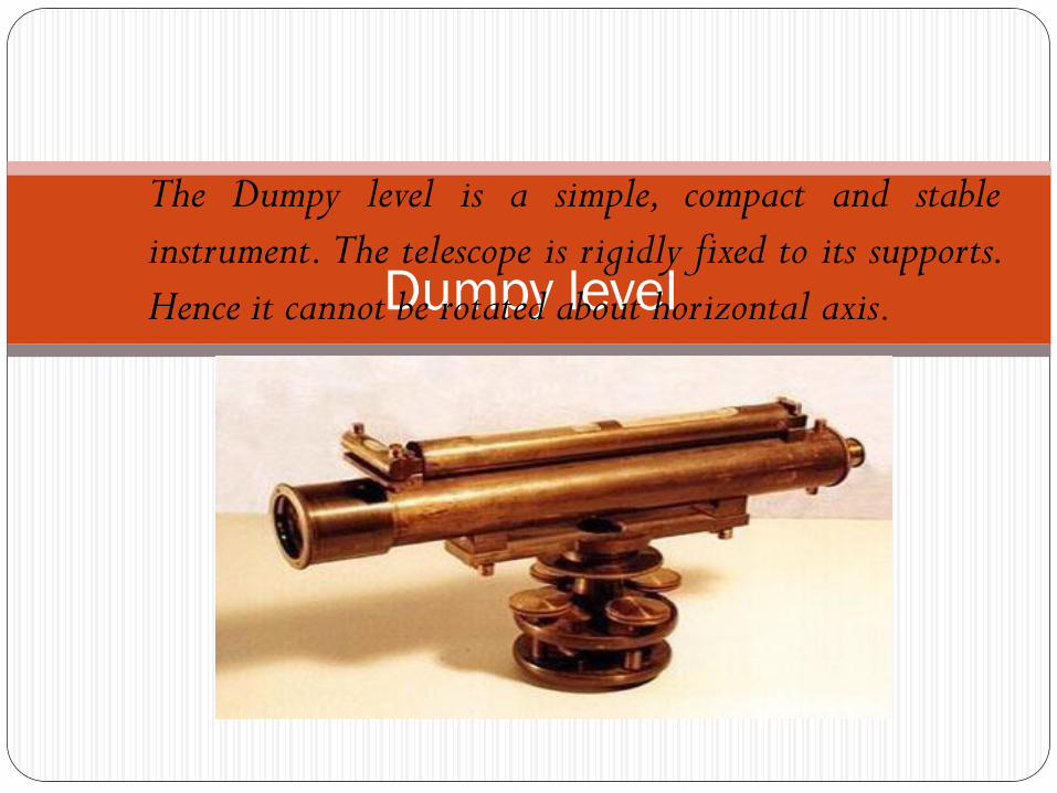
Dumpy level
The Dumpy level is a simple, compact and stable
instrument. The telescope is rigidly fixed to its supports.
Hence it cannot be rotated about horizontal axis.
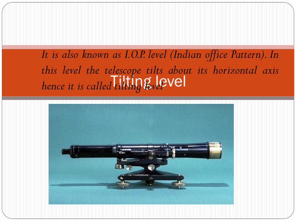
Tilting level
It is also known as I.O.P. level (Indian office Pattern). In
this level the telescope tilts about its horizontal axis
hence it is called tilting level
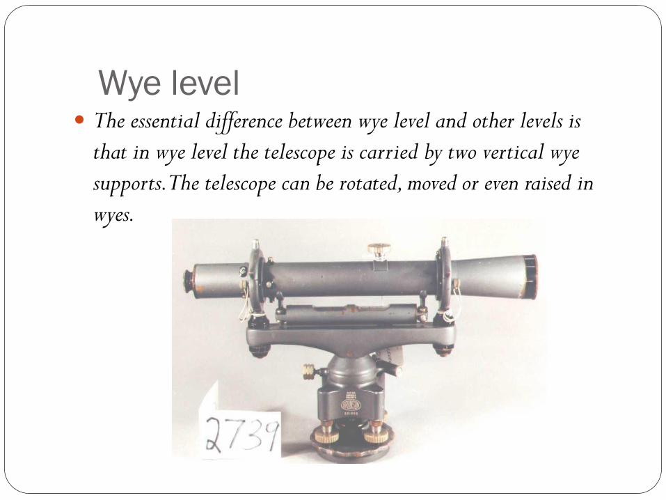
Wye level The essential difference between wye level and other levels is
that in wye level the telescope is carried by two vertical wye
supports. The telescope can be rotated, moved or even raised in
wyes.
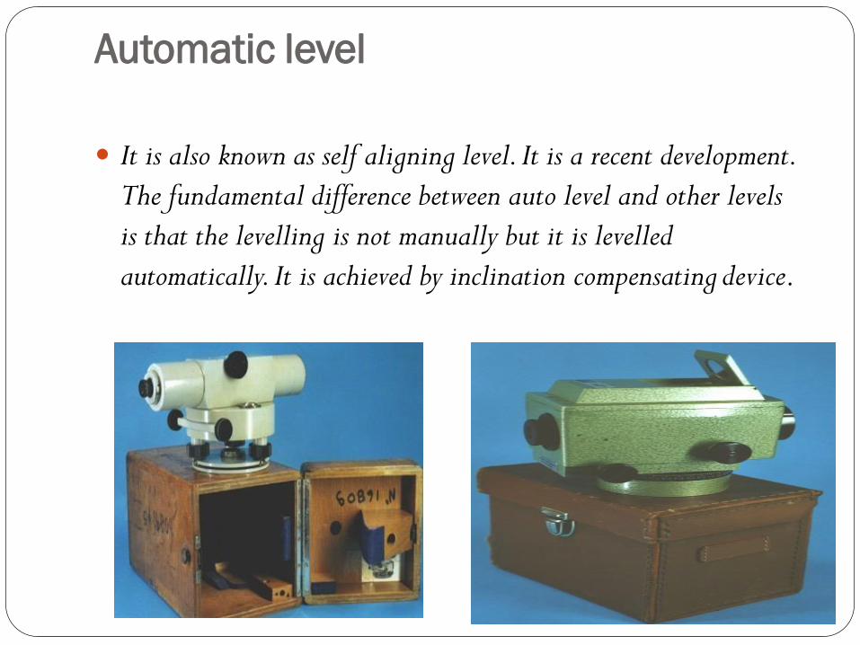
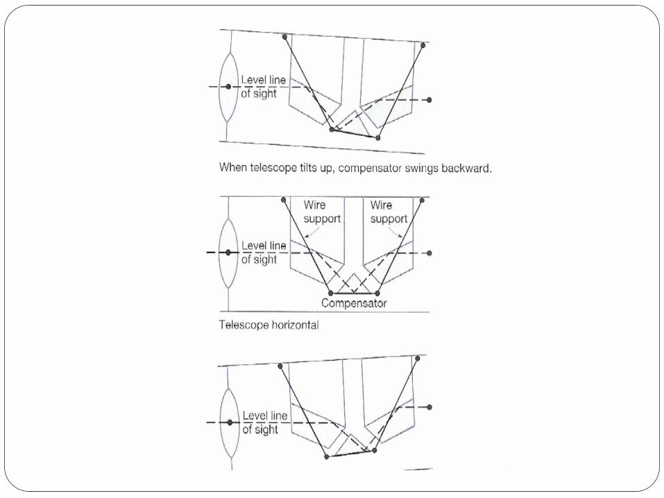
Automatic level
It is also known as self aligning level. It is a recent development.
The fundamental difference between auto level and other levels
is that the levelling is not manually but it is levelled
automatically. It is achieved by inclination compensating device.
Levelling Staffs Levelling staffs are scales on which these distances
are measured.
Levelling staffs are of two types
Self reading staff
Target staff
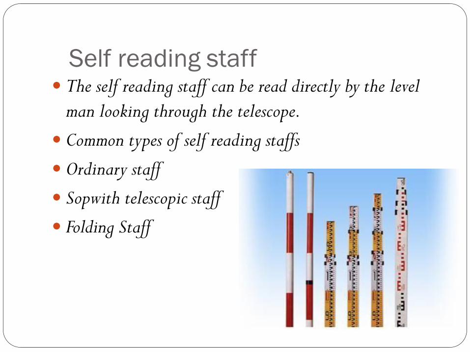
Self reading staff The self reading staff can be read directly by the level
man looking through the telescope.
Common types of self reading staffs
Ordinary staff
Sopwith telescopic staff
Folding Staff

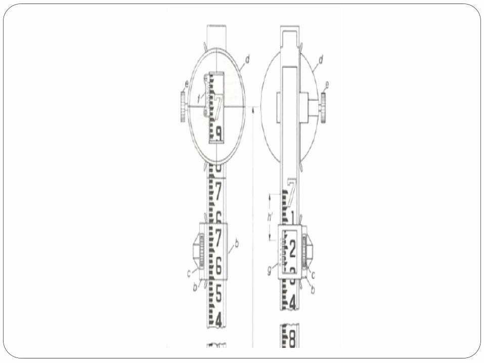
Target staff For very precise works and sight target staff are used.A movable
target is provided in this staff.A vernier is provided on
target to give precise reading. In target staff level man
directs the staff man to move the target up and down until
it bisects by the line of sight.The staff man observe the staff
reading
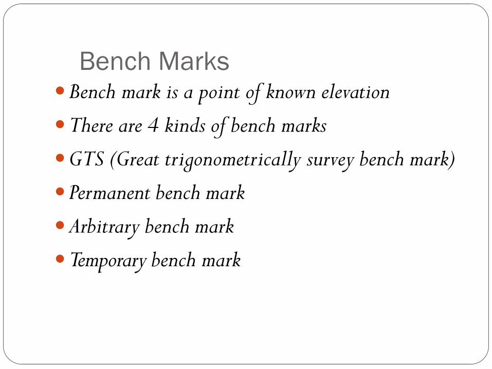
Bench MarksBench mark is a point of known elevation
There are 4 kinds of bench marks
GTS (Great trigonometrically survey bench mark)
Permanent bench mark
Arbitrary bench mark
Temporary bench mark
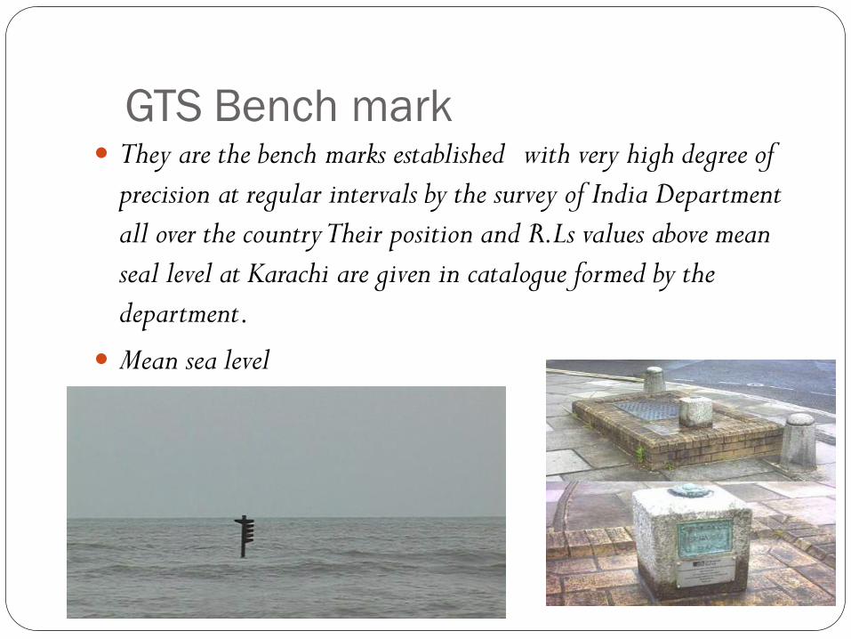
GTS Bench mark They are the bench marks established with very high degree of
precision at regular intervals by the survey of India Department
all over the country Their position and R.Ls values above mean
seal level at Karachi are given in catalogue formed by the
department.
Mean sea level
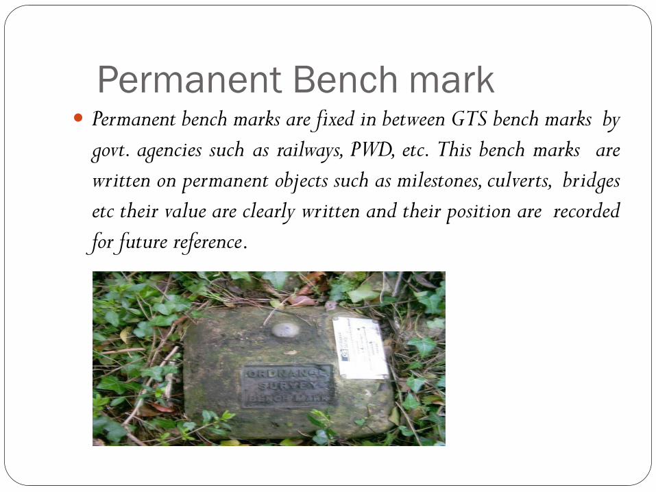
Permanent Bench mark Permanent bench marks are fixed in between GTS bench marks by
govt. agencies such as railways, PWD, etc. This bench marks are
written on permanent objects such as milestones, culverts, bridges
etc their value are clearly written and their position are recorded
for future reference.
Arbitrary bench marks:-These are reference points whose
R.L.s are arbitrarily assumed.They are used in small works
such bench mark may be assumed as 100. or 50 m
Temporary bench marks:-They are the reference points
established during the levelling operations when there is a
break in work, or at the end of day’s work the value of
reduced levels are marked on some permanent objects such
as stones, trees etc.

Temporary Adjustments of a level These adjustments are performed at every setup of
instrument
Setting up of level
Levelling of telescope
Focusing of the eye peace
Focusing of object glass

Setting up the level:-Thisincludes
A) Fixing the instrument on tripod
B) Levelling the instrument approximately byTripod
Levelling:- Levelling Levelling is done with the help of foot screws.The purpose of levelling is to make vertical axis truly vertical. It isdone with the help of foot screws
A) Place the telescope parallel to a pair of foot screw then hold the foot screws between thumb and first finger and turn them either inward or outward until the longitudinal bubble comes in the centre.
B)Turn the telescope through 900 so that it lies parallel to third footscrew, turn the screw until the bubble comes in the centre.
Focusing the eye piece:- To focus the eye piece, hold a white
paper in front of object glass, and move the eye piece in or
out till the cross hair are distinctly seen.
Focusing of object glass:- Direct the telescope to the
levelling staff and on looking through the telescope, turn
the focusing screw till the image appears clear and sharp.
Classification of levelling Simple levelling
Differential leveling
Fly levelling
Check levelling
Profile levelling
Cross levelling
Reciprocal levelling
Precise levelling
Trignometric levelling
Barometric levelling
Hypersometric levelling
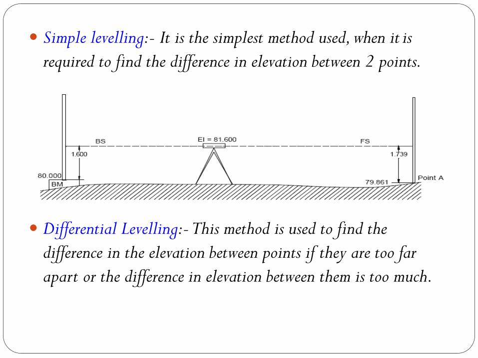
Simple levelling:- It is the simplest method used, when it is
required to find the difference in elevation between 2 points.
Differential Levelling:-This method is used to find the
difference in the elevation between points if they are too far
apart or the difference in elevation between them is too much.
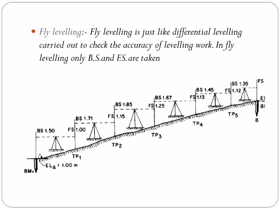
Fly levelling:- Fly levelling is just like differential levelling
carried out to check the accuracy of levelling work. In fly
levelling only B.S.and F.S. are taken
Check levelling:-This kind of levelling is carried out to
check the accuracy of work. It is done at the end of the days
work in the form of fly levelling to connect the finishing
point and starting point.
Profile levelling or L-Section:-This method is used for
taking levels along the centre line of any alignment like
road, railway canal etc.The object is to determine the
undulations of the ground surface along the alignment
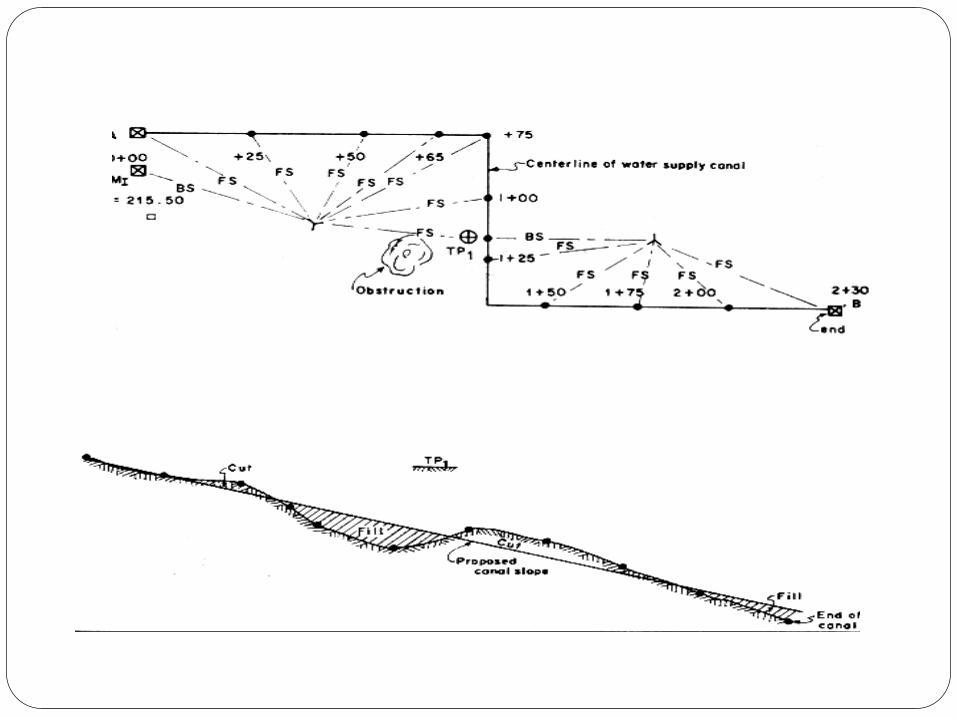
Cross- sectioning:- This operation is carried out
perpendicular to alignment at an interval of 10, 20 ,30,
40 m.The idea is to make an estimate of earthwork.
Precise levelling:- It is used for establishing bench marks for
future public use. It is carried out with high degree of
accuracy using advanced instruments
Trignometric levelling:- In this method vertical distances
between points are computed by observing horizontal
distances and vertical angle between points.
Barometric levelling:- In this method the altitude difference
is determined by means of a barometer.
Hyposometric levelling:- The working of Hyposometry for
determining the elevation depends upon the fact that the
temperature at which water boils varies with the
atmospheric pressure. The boiling point of water reduces at
higher altitude thus knowing the boiling point of water, the
atmospheric pressure can be calculated and knowing the
atmospheric pressure altitude or elevation can be
determined
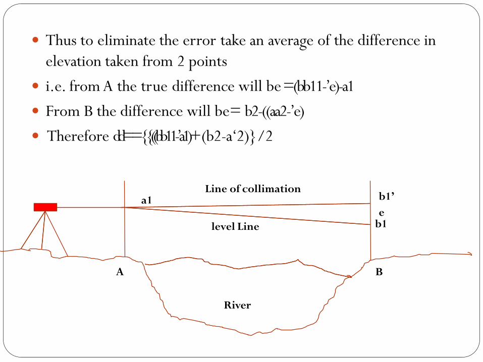
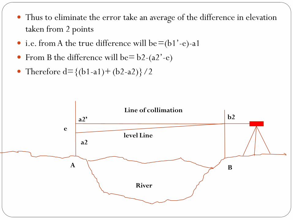
Reciprocal levelling
Reciprocal levelling:-This method is adopted to accurately
determine the difference of level between two points which are far
apart. It is also used when it is not possible to set up level in mid way
between two points
Let A and B be the two points on opposite banks of a river. It is
required to find out the level difference between A & B
Set up the level very near to A and take the reading at A and B let
the reading be a1 and b1
Shift the level and set up very near to B and observe A and B to get
reading a2 and b2
Let d is the true difference of level between A and B, and e= error
due to curvature, refrection and imperfect adjustment.
b1’
e b1
Thus to eliminate the error take an average of the difference in
elevation taken from 2 points
i.e. from A the true difference will be=(bb11-’e)-a1
From B the difference will be= b2-((aa2-’e)
Therefore dd=={{((bb11-’a1)+ (b2-a‘2)}/2
a1Line of collimation
level Line
A B
River
b2
a2
e
a2’
Line of collimation
level Line
A B
River
Thus to eliminate the error take an average of the difference in elevation
taken from 2 points
i.e. from A the true difference will be=(b1’-e)-a1
From B the difference will be= b2-(a2’-e)
Therefore d={(b1-a1)+ (b2-a2)}/2
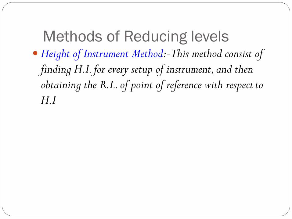
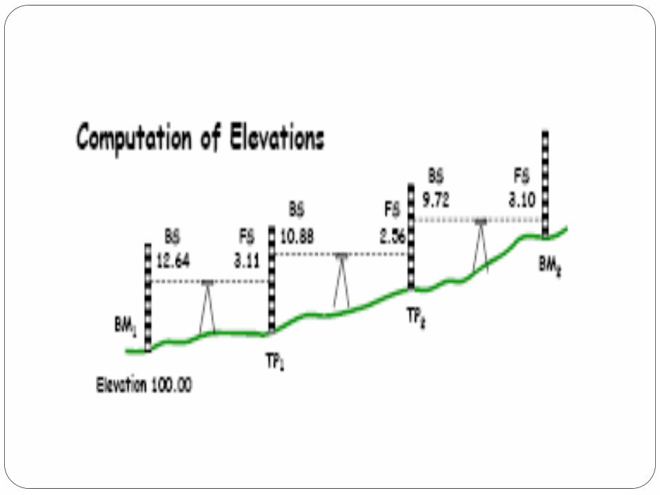
Methods of Reducing levels Height of Instrument Method:-This method consist of
finding H.I. for every setup of instrument, and then
obtaining the R.L. of point of reference with respect to
H.I
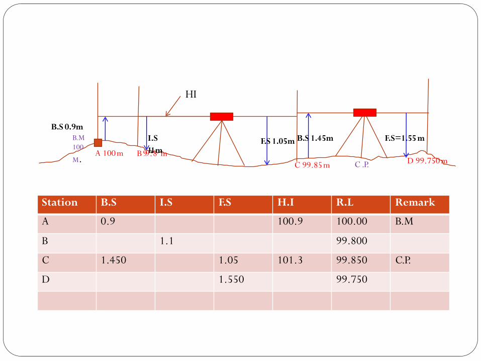
Station B.S I.S F.S H.I R.L Remark
A 0.9 100.9 100.00 B.M
B 1.1 99.800
C 1.450 1.05 101.3 99.850 C.P.
D 1.550 99.750
F.S=1.55 m
A 100m
I.S
B 991..18mm
F.S 1.05m B.S 1.45m
C 99.85m D 99.750m
B.S 0.9mB.M
100
M.
HI
C .P.
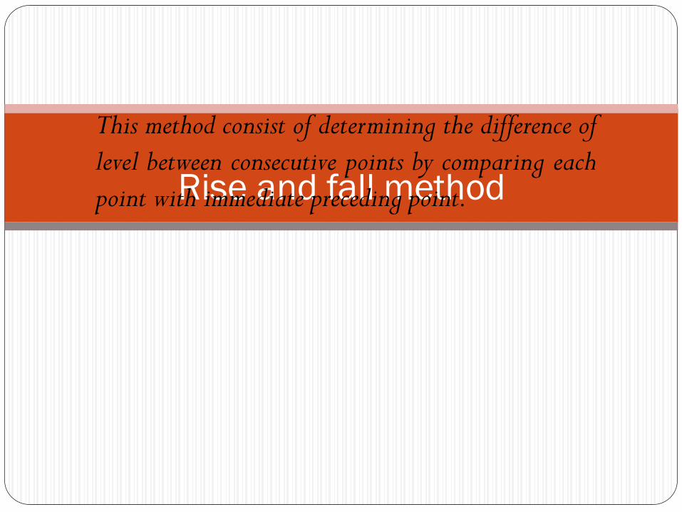
Rise and fall method
This method consist of determining the difference of
level between consecutive points by comparing each
point with immediate preceding point.
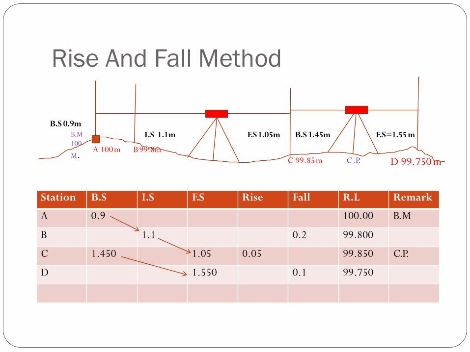
Rise And Fall Method
Station B.S I.S F.S Rise Fall R.L Remark
A 0.9 100.00 B.M
B 1.1 0.2 99.800
C 1.450 1.05 0.05 99.850 C.P.
D 1.550 0.1 99.750
F.S1.05m B.S 1.45m F.S=1.55 m
A 100m
I.S 1.1m
B 99.8m
C 99.85m
B.S 0.9mB.M
100
M.D 99.750 mC .P.
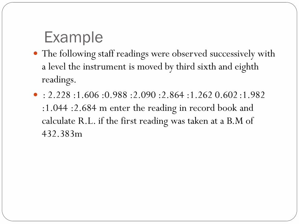
Example The following staff readings were observed successively with
a level the instrument is moved by third sixth and eighth
readings.
: 2.228 :1.606 :0.988 :2.090 :2.864 :1.262 0.602 :1.982
:1.044 :2.684 m enter the reading in record book and
calculate R.L. if the first reading was taken at a B.M of
432.383m
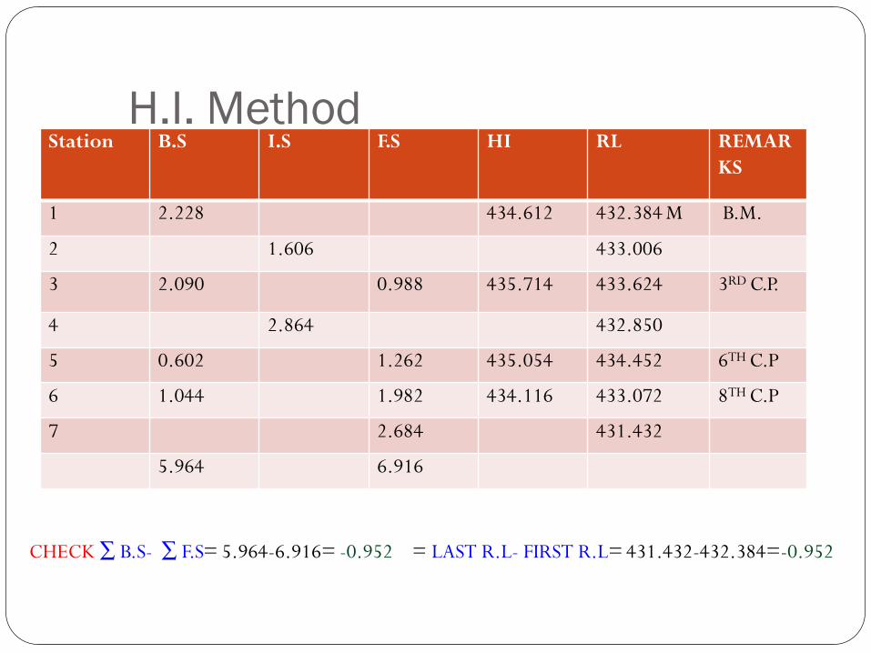
H.I. MethodStation B.S I.S F.S HI RL REMAR
KS
1 2.228 434.612 432.384 M B.M.
2 1.606 433.006
3 2.090 0.988 435.714 433.624 3RD C.P.
4 2.864 432.850
5 0.602 1.262 435.054 434.452 6TH C.P
6 1.044 1.982 434.116 433.072 8TH C.P
7 2.684 431.432
5.964 6.916
CHECK ∑ B.S- ∑ F.S= 5.964-6.916= -0.952 = LAST R.L- FIRST R.L= 431.432-432.384=-0.952
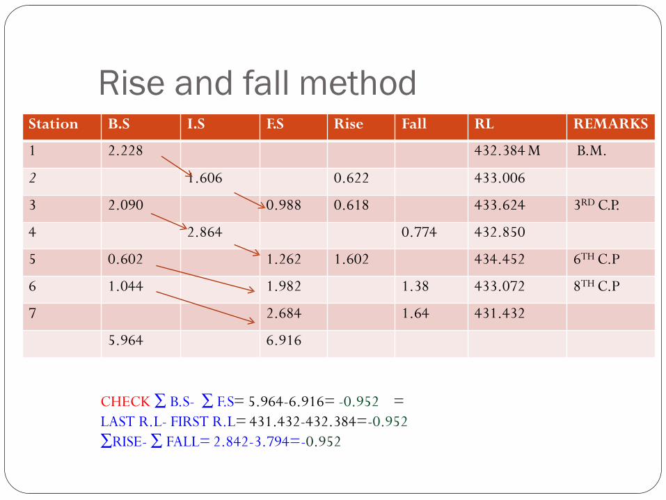
Rise and fall methodStation B.S I.S F.S Rise Fall RL REMARKS
1 2.228 432.384 M B.M.
2 1.606 0.622 433.006
3 2.090 0.988 0.618 433.624 3RD C.P.
4 2.864 0.774 432.850
5 0.602 1.262 1.602 434.452 6TH C.P
6 1.044 1.982 1.38 433.072 8TH C.P
7 2.684 1.64 431.432
5.964 6.916
CHECK ∑ B.S- ∑ F.S= 5.964-6.916= -0.952 =
LAST R.L- FIRST R.L= 431.432-432.384=-0.952
∑RISE- ∑ FALL= 2.842-3.794=-0.952
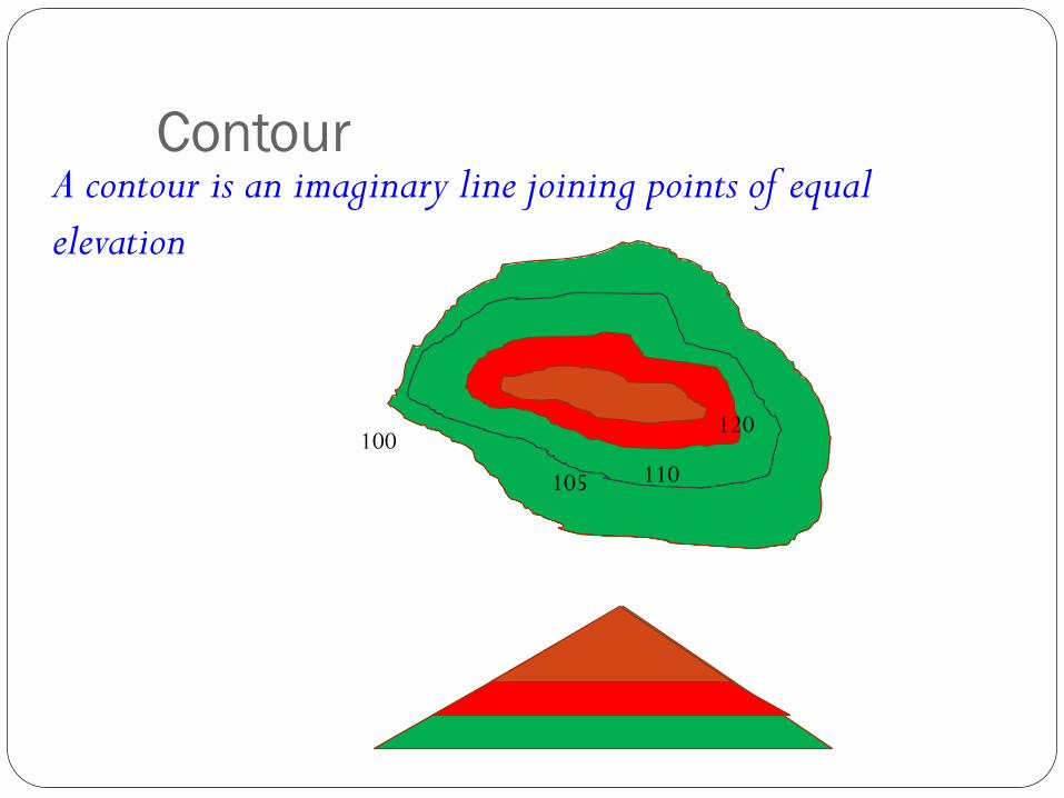
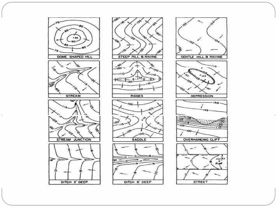
Contour
100
105 110
120
A contour is an imaginary line joining points of equal
elevation
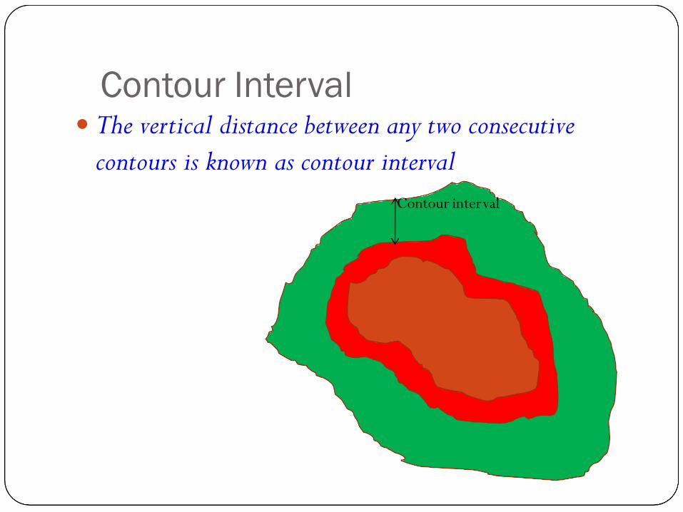
Contour Interval The vertical distance between any two consecutive
contours is known as contour interval
Contour interval
Characteristics of contour lines A series of contour lines with higher value inside
indicate a hill
A series of contour lines with lower value inside the loop always indicate depression
Close contour lines indicate steep slope
Wide contour lines indicate flatter slope
Contour lines never cross each other except in case of overhanging cliff.
All points on a contour lines have equal elevation
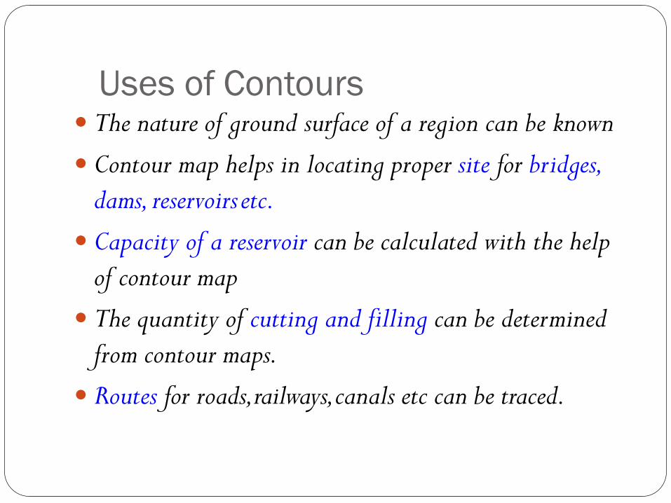
Uses of Contours The nature of ground surface of a region can be known
Contour map helps in locating proper site for bridges,
dams, reservoirs etc.
Capacity of a reservoir can be calculated with the help
of contour map
The quantity of cutting and filling can be determined
from contour maps.
Routes for roads,railways,canals etc can be traced.
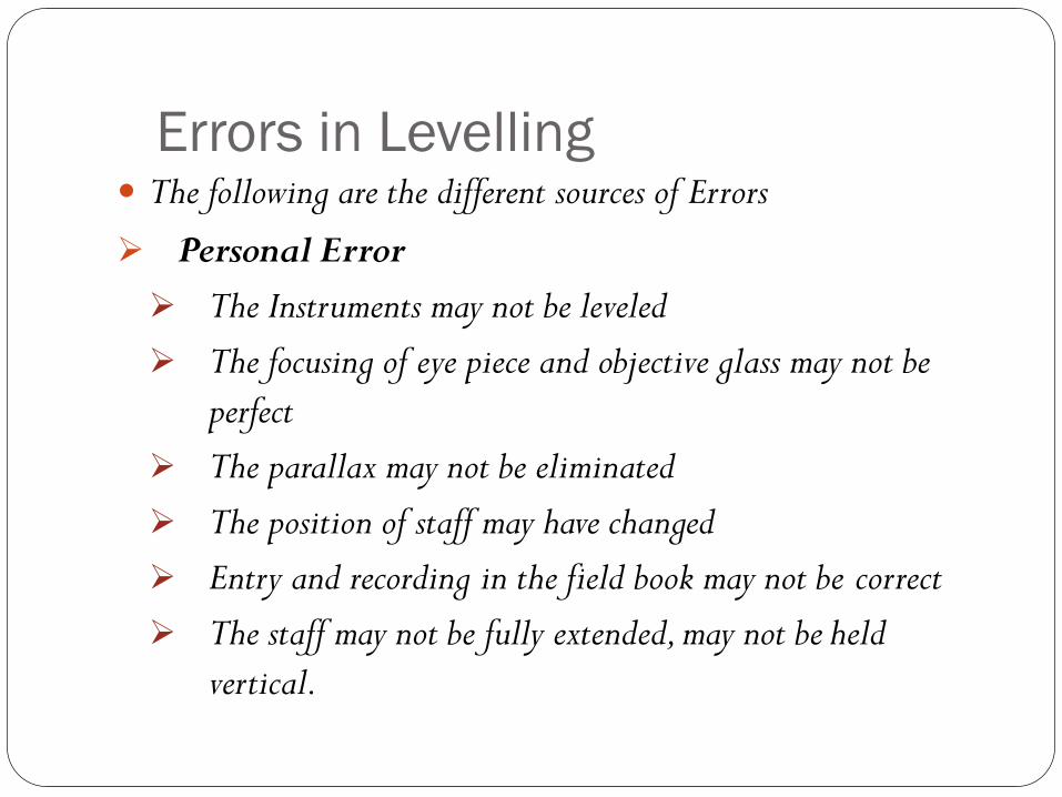
Errors in Levelling The following are the different sources of Errors
Personal Error
The Instruments may not be leveled
The focusing of eye piece and objective glass may not be
perfect
The parallax may not be eliminated
The position of staff may have changed
Entry and recording in the field book may not be correct
The staff may not be fully extended, may not be held
vertical.
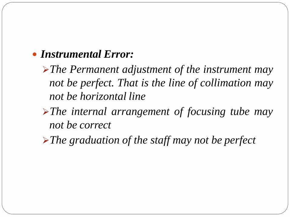
Instrumental Error:
The Permanent adjustment of the instrument may
not be perfect. That is the line of collimation may
not be horizontal line
The internal arrangement of focusing tube may
not be correct
The graduation of the staff may not be perfect
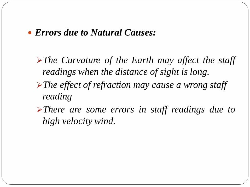
Errors due to Natural Causes:
The Curvature of the Earth may affect the staff
readings when the distance of sight is long.
The effect of refraction may cause a wrong staff
reading
There are some errors in staff readings due to
high velocity wind.
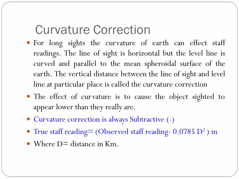
Curvature Correction For long sights the curvature of earth can effect staff
readings. The line of sight is horizontal but the level line is
curved and parallel to the mean spheroidal surface of the
earth. The vertical distance between the line of sight and level
line at particular place is called the curvature correction
The effect of curvature is to cause the object sighted to
appear lower than they really are.
Curvature correction is always Subtractive (-)
True staff reading= (Observed staff reading- 0.0785 D2 ) m
Where D= distance in Km.
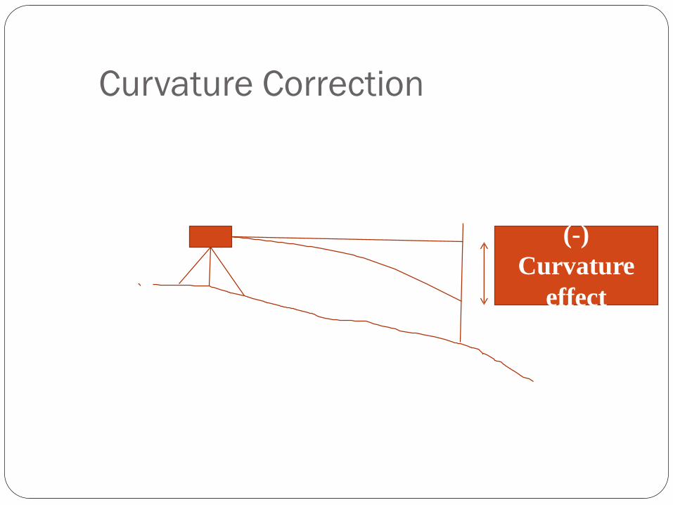
Curvature Correction
(-)
Curvature
effect
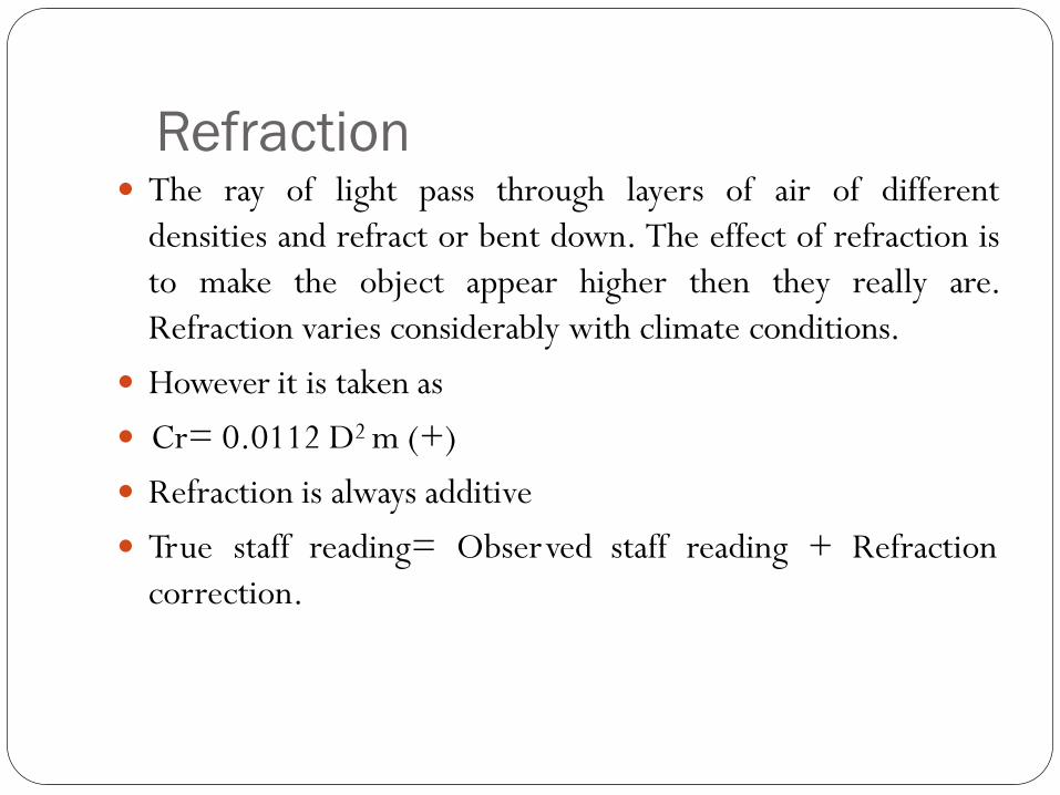
Refraction The ray of light pass through layers of air of different
densities and refract or bent down. The effect of refraction is
to make the object appear higher then they really are.
Refraction varies considerably with climate conditions.
However it is taken as
Cr= 0.0112 D2 m (+)
Refraction is always additive
True staff reading= Observed staff reading + Refraction
correction.
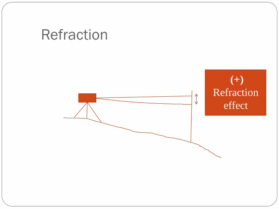
Refraction
(+)
Refraction
effect
GPS Surveying
GPS -- how it works
GPS -- Garmin 12
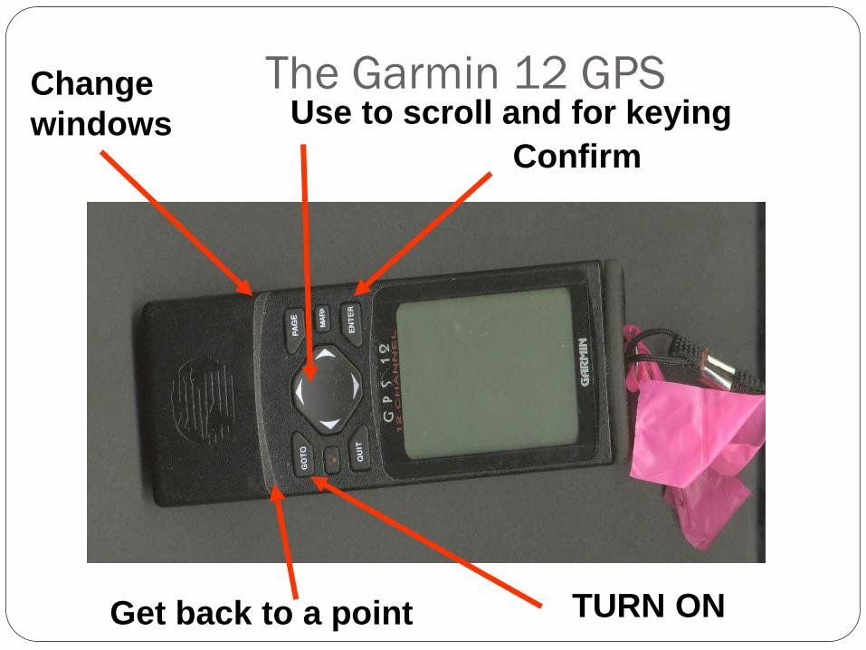
The Garmin 12 GPSChange
windowsConfirm
Get back to a point
Use to scroll and for keying
TURN ON
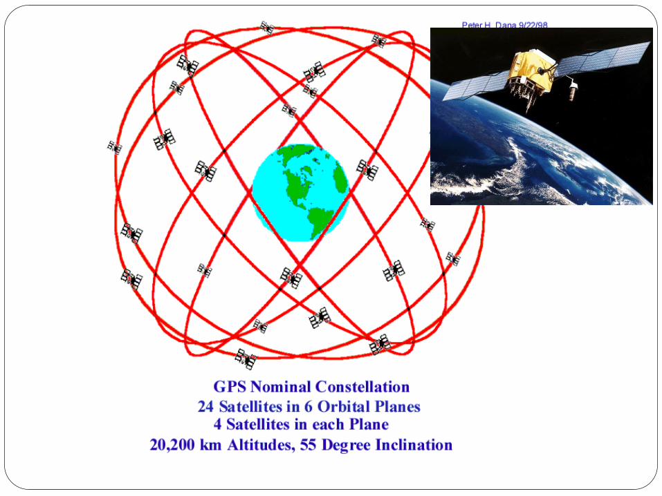
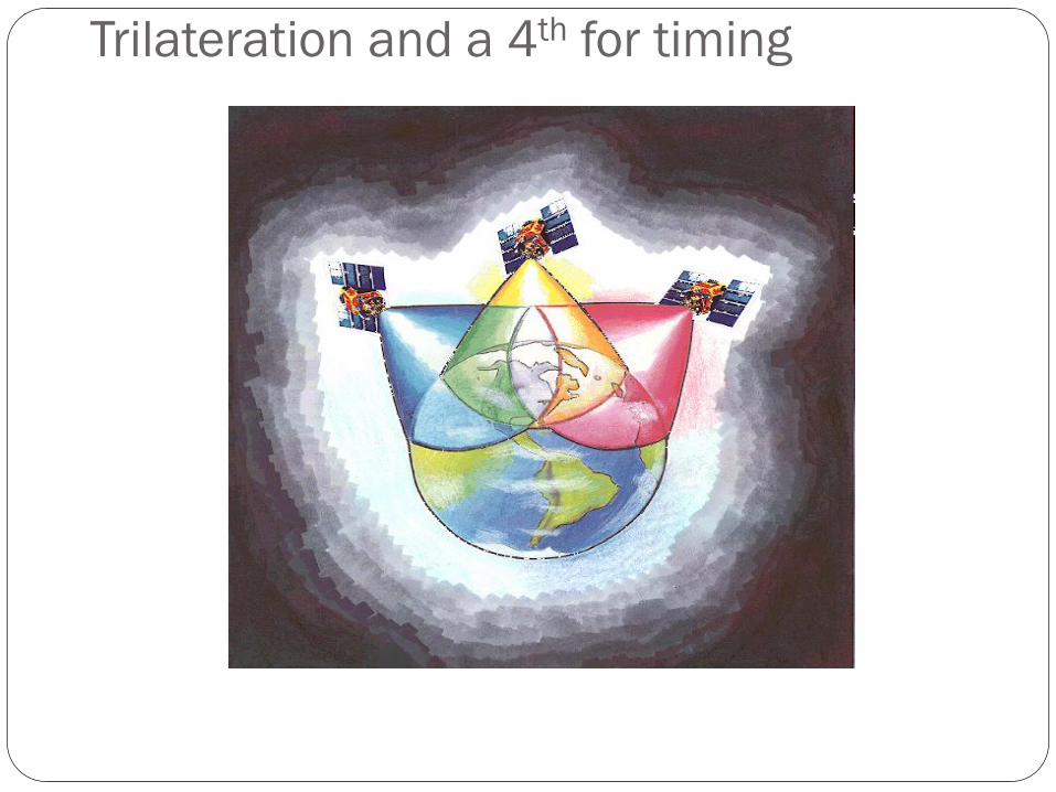
Trilateration and a 4th for timing
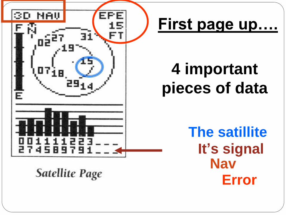
First page up….
4 important
pieces of data
The satilliteIt’s signal
NavError
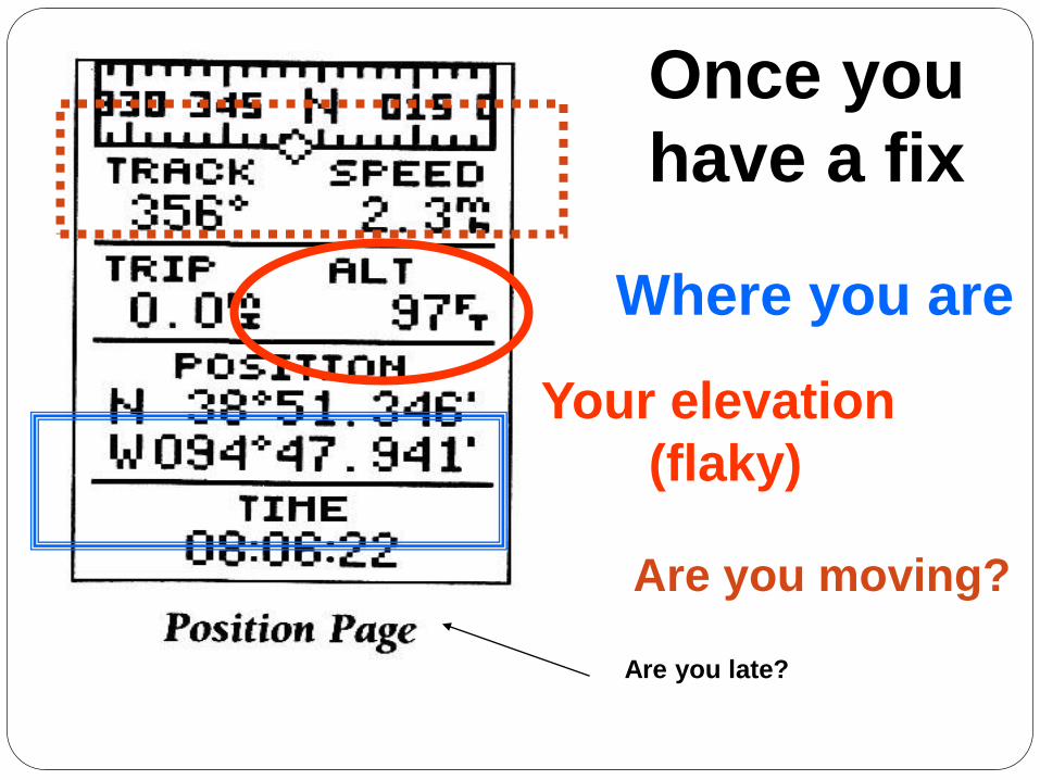
Once you
have a fix
Where you are
Your elevation
(flaky)
Are you late?
Are you moving?
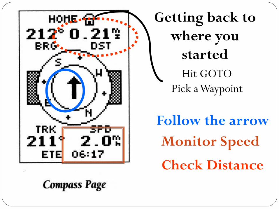
Getting back to
where you
started
Follow the arrow
Monitor Speed
Check Distance
Hit GOTO
Pick a Waypoint
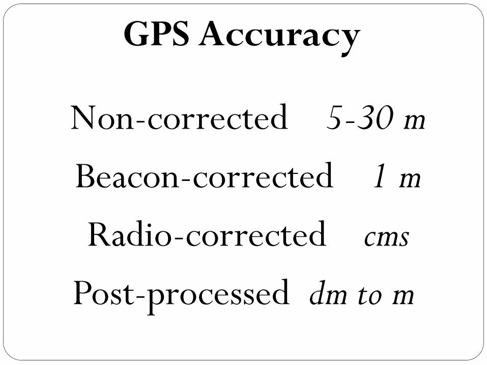
Non-corrected 5-30 m
Beacon-corrected 1 m
Radio-corrected cms
Post-processed dm to m
GPS Accuracy
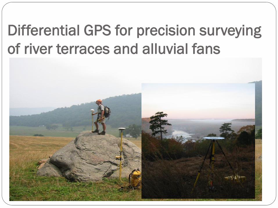
Differential GPS for precision surveying
of river terraces and alluvial fans
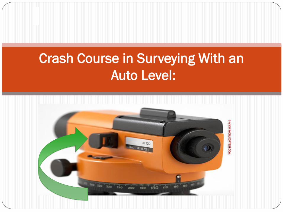
Crash Course in Surveying With an
Auto Level:
:( (:
1
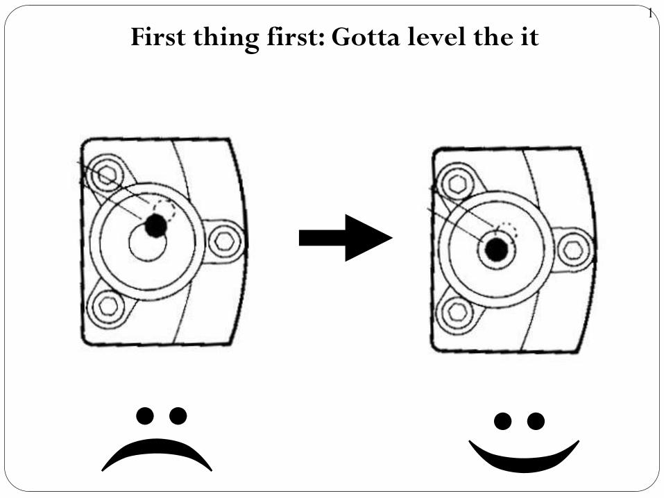
First thing first: Gotta level the it
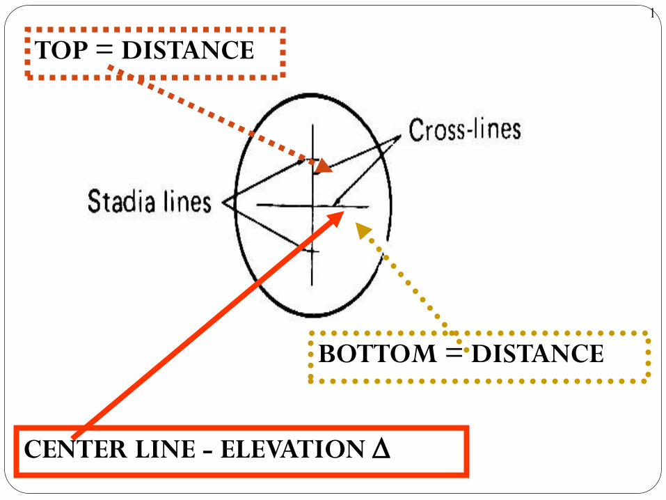
CENTER LINE - ELEVATION D
BOTTOM = DISTANCE
TOP = DISTANCE
1
1
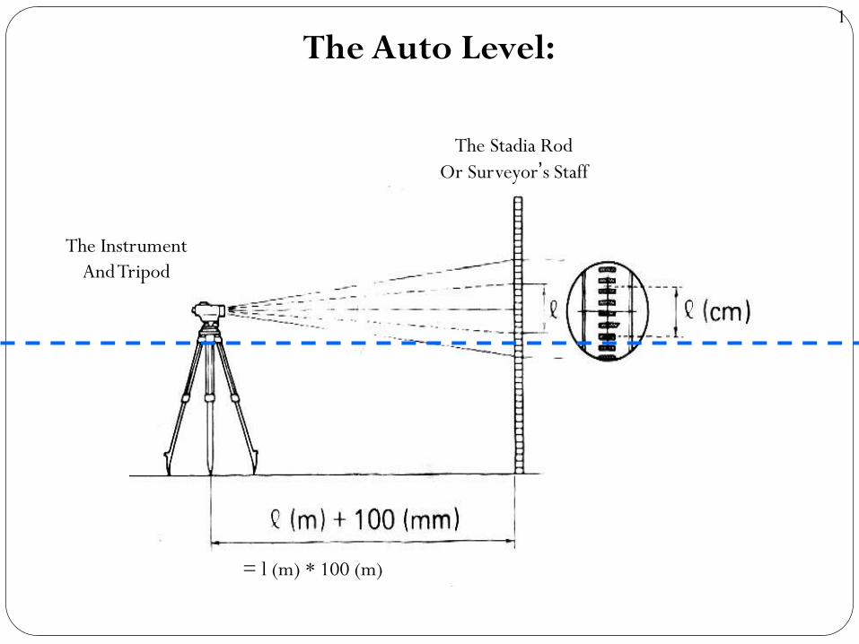
The Auto Level:
The Instrument
And Tripod
The Stadia Rod
Or Surveyor’s Staff
= l (m) * 100 (m)
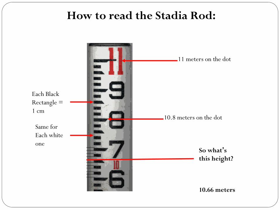
How to read the Stadia Rod:
11 meters on the dot
10.8 meters on the dot
Each Black
Rectangle =
1 cm
Same for
Each white
oneSo what’s
this height?
10.66 meters
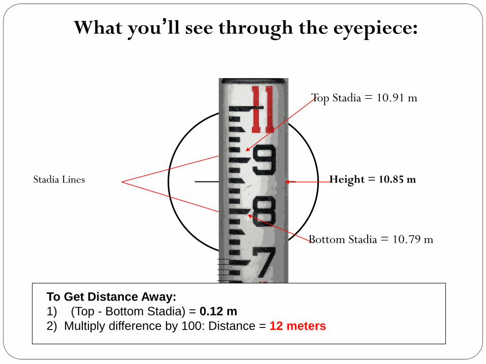
What you’ll see through the eyepiece:
Stadia Lines Height = 10.85 m
Top Stadia = 10.91 m
Bottom Stadia = 10.79 m
To Get Distance Away:
1) (Top - Bottom Stadia) = 0.12 m
2) Multiply difference by 100: Distance = 12 meters
1
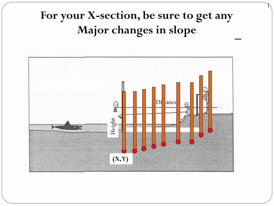
For your X-section, be sure to get any
Major changes in slope
Distance
Hei
ght
(X, Y)
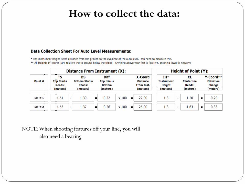
How to collect the data:
NOTE: When shooting features off your line, you will
also need a bearing
?
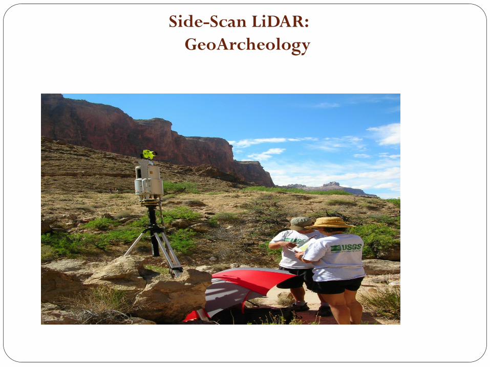
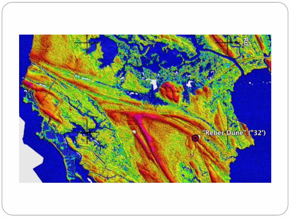
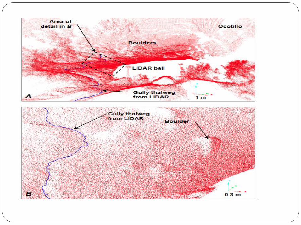
Side-Scan LiDAR:
GeoArcheology
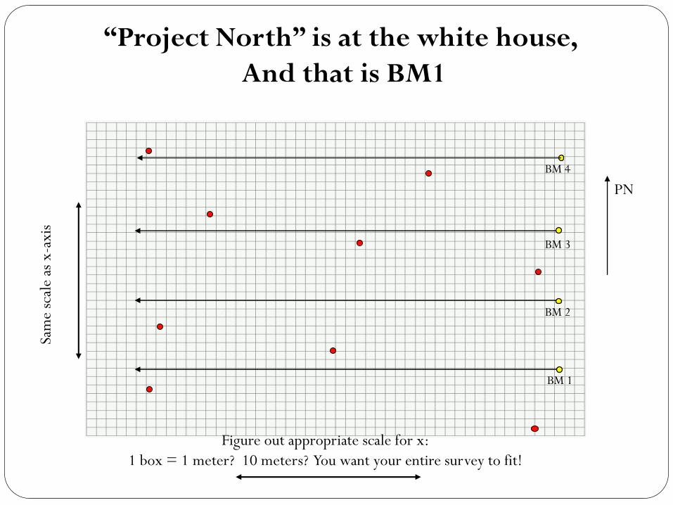
“Project North” is at the white house,
And that is BM1
Figure out appropriate scale for x:
1 box = 1 meter? 10 meters? You want your entire survey to fit!
Sam
e sc
ale
as x
-axi
s
BM 1
BM 2
BM 3
BM 4
PN