levelling – a practical guide - land surveying software - a practical... · levelling – a...
TRANSCRIPT

Levelling – A Practical Guide The process of Levelling explained A practical guide aimed at land surveyors, engineers and archaeologists explaining the practice of levelling – the process of determining the height above sea level, or some other local datum, of points in space.
2016
Bryan Farrar landsurveyingsoftware.co.uk

Levelling – A Practical Guide 1
Copyright ©Bryan R Farrar – 2016 – All rights reserved. www.landsurveyingsoftware.co.uk
Contents Introduction ............................................................................................................................................ 2
Some concepts defined ........................................................................................................................... 2
Horizontal and Vertical ....................................................................................................................... 2
Height/Level ........................................................................................................................................ 2
Precision and Accuracy ........................................................................................................................... 3
Precision .............................................................................................................................................. 3
Accuracy .............................................................................................................................................. 3
Basic concept of levelling ........................................................................................................................ 3
Levelling in Practice................................................................................................................................. 5
Surveyor’s Level .................................................................................................................................. 5
Tripod .................................................................................................................................................. 5
Telescopic Measuring Staff ................................................................................................................. 5
Method of recording observations ..................................................................................................... 5
Surveyor .............................................................................................................................................. 5
Assistant .............................................................................................................................................. 5
Brief overview of the levelling process ................................................................................................... 6
Setting up your level ............................................................................................................................... 7
Focussing the cross-hairs ........................................................................................................................ 7
Placing the measuring staff ..................................................................................................................... 7
Recording Observations .......................................................................................................................... 8
A step-by-step example .......................................................................................................................... 9
Finding the Reduced Level of a High Point (Inverted Staff) .................................................................. 24
Sources of Errors ................................................................................................................................... 25
Tips to remember ................................................................................................................................. 25
Levelling – A Practical Guide 2
Copyright ©Bryan R Farrar – 2016 – All rights reserved. www.landsurveyingsoftware.co.uk
Levelling – A Practical Guide
Introduction Levelling, in land surveying terms, is the process of determining the difference in height between
two points in space. This guide takes you through the basic concepts and theory, and then takes a
step-by-step approach to demonstrating and explaining the practicalities.
Some concepts defined
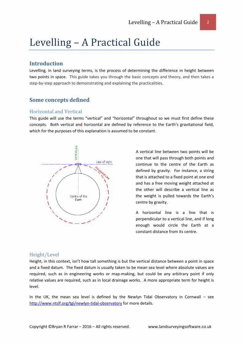
Horizontal and Vertical This guide will use the terms “vertical” and “horizontal” throughout so we must first define these
concepts. Both vertical and horizontal are defined by reference to the Earth’s gravitational field,
which for the purposes of this explanation is assumed to be constant.
A vertical line between two points will be
one that will pass through both points and
continue to the centre of the Earth as
defined by gravity. For instance, a string
that is attached to a fixed point at one end
and has a free moving weight attached at
the other will describe a vertical line as
the weight is pulled towards the Earth’s
centre by gravity.
A horizontal line is a line that is
perpendicular to a vertical line, and if long
enough would circle the Earth at a
constant distance from its centre.
Height/Level Height, in this context, isn’t how tall something is but the vertical distance between a point in space
and a fixed datum. The fixed datum is usually taken to be mean sea level where absolute values are
required, such as in engineering works or map-making, but could be any arbitrary point if only
relative values are required, such as in local drainage works. A more appropriate term for height is
level.
In the UK, the mean sea level is defined by the Newlyn Tidal Observatory in Cornwall – see
http://www.ntslf.org/tgi/newlyn-tidal-observatory for more details.

Levelling – A Practical Guide 3
Copyright ©Bryan R Farrar – 2016 – All rights reserved. www.landsurveyingsoftware.co.uk
Precision and Accuracy
Precision No distance in the real word can be measured exactly, but it can be measured to an appropriate
precision. For example, it would be nonsense to state that the distance from London to Paris is
342,806.457metres. Saying that the distance from London to Paris is 840Km would be more
appropriate. This is because the positions of London and Paris are vague and cannot be defined to
millimetre precision, stating the distance to the nearest 10 kilometres is a more appropriate level of
precision. By refining our definitions of London and Paris we could increase our by precision so we
could say the distance from the centre of London to the centre of Paris is 342.8Km, i.e. to the
nearest hundred metres.
The level of precision used when levelling will depend upon the requirements of the project. Civil
Engineering works will require millimetre precision; drainage works may be less. “Precision
Levelling”, to sub-millimetre precision, and requiring specialist equipment is beyond the scope of
this guide.
Accuracy Accuracy can be thought of as the effect of errors on the result of a measurement. There are many
sources of errors during the levelling process but their effects can be greatly reduced by following
the procedures below. A table of error sources, their impact and avoidance is included towards the
end of this guide.
Basic concept of levelling Imagine we have two points on the
ground; point A is where we are
standing and point B which is a few
paces away down a slope. We want
to know how much lower point B is
compared to point A i.e. what is the
difference in height (or level)
between points A and B?
In the figure opposite, the difference
in level between point A on the
ground and point B on the ground is
found by projecting a horizontal line
out from point A and then measuring the distance vertically from point B up to this line.
In practice we can discover this by defining a horizontal plane above both points and then measuring
vertically from each point up to this horizontal plane. The difference between the two
measurements will be the difference in height (level) between the two points.

Levelling – A Practical Guide 4
Copyright ©Bryan R Farrar – 2016 – All rights reserved. www.landsurveyingsoftware.co.uk
For instance, we measure a distance of 1.0m from point A vertically up to our horizontal plane. In
the figure above this is labelled as htA. We now move down the slope to point B and measure a
distance of 1.5m vertically up to our horizontal plane. In the figure above this is labelled as htB. The
difference between the two values is 1.5m – 1.0m = 0.5m. In the figure above this is labelled as h
(delta h). This is the difference in height, or the difference in level, between the two points.
Because point B is lower than point A then this difference is referred to as a fall. If it had been
higher then it would be called a rise.
HPC in the figure above stands for Height of Plane of Collimation and is the arbitrary horizontal plane
from which to measure. This will be explained in more detail later.
Assume we know that point A in the figure above is 100 metres above mean sea level. This is called
its Reduced Level and is labelled in the figure above as RLA. To calculate the Reduced Level of point
B (RLB) we can see that:
h = htA – htB = 1.0 -1.5 = -0.5
RLB = RLA + h
RLB = 100 + -0.5 = 99.5 metres above mean sea level.
To find the Reduced Level of a point C further down the slope we can repeat the process, but this
time start from point B and so on, finding the Reduced Level of points as we progress. If we know
the Reduced Level of the point that we finish on, either because it has been previously calculated, or
we have returned to the point at which we started then we can compare the known Reduced Level
with our calculated Reduced Level. The difference in values is known as the misclosure and is a
measure of the accuracy of our work. There will be a fuller explanation of misclosures later.

Levelling – A Practical Guide 5
Copyright ©Bryan R Farrar – 2016 – All rights reserved. www.landsurveyingsoftware.co.uk
Levelling in Practice You will need (minimum):
Surveyor’s level
Tripod
Telescopic Measuring staff
Some means of recording observations (pen/paper, electronic device).
Surveyor
Assistant
Surveyor’s Level - We define our horizontal plane (HPC) using an instrument called a surveyor’s level or
usually abbreviated to just level. A level is basically a telescope, with cross-hairs in the
eye-piece, attached to a spirit-level so that the line of sight defined by the cross-hairs
can be made “horizontal”. It should be remembered that a line of sight will begin to
deviate from the horizontal over distance, as the horizontal will begin to dip down over
the horizon due to the curvature of the Earth, whereas the line of sight is a straight line
and will continue out into space. In practise though, this can usually be ignored as the
line of sight will coincide sufficiently with the horizontal if observing over short
distances.
Tripod - Three-legged stand, upon which the level is mounted; made from aluminium or wood.
Telescopic Measuring Staff - Usually made from aluminium box section, the measuring staff has graduations marked
on its front face, starting at zero at the base and increasing up the staff.
Method of recording observations - This usually takes the form of a booking sheet, which is a table, formatted for the logical
entry of data. Knightwood LevelBook Pro has the ability to print out ready-made
booking sheets. The method of data entry will be studied in detail later.
Surveyor - The person making the observations through the level.
Assistant - The person holding the measuring staff.

Levelling – A Practical Guide 6
Copyright ©Bryan R Farrar – 2016 – All rights reserved. www.landsurveyingsoftware.co.uk
Brief overview of the levelling process The level-run should always start at a point of known Reduced Level. The details of this point and its
Reduced Level are entered onto the booking sheet. The measuring staff is placed on this point and
held vertically. The Surveyor’s Level is then set up no more than approx. 15m away and a reading
taking to the measuring staff. This is known as a back-sight and the value is entered in the
appropriate place on the booking sheet. The distance from staff to level should be measured by
pacing.
The level stays where it is, but the staff is now moved to a point further along the level-run but the
same distance from the level as before. The reason why the distance from the back-sight position to
the level, and the distance to the foresight position and the level should be equal helps eliminate a
possible error and will be explained in greater depth later below. This point may be a point of which
the Reduced Level is required, or it may be an arbitrary point used to progress the level-run. If it is
an arbitrary point then it is known as a change point (CP). A reading is now made to the staff at this
point and this is known as a fore-sight and is entered onto the booking sheet accordingly.
Now, the staff remains where it is and the level is moved further along the level-run and a reading
taken back to the staff. This is entered as a back-sight on the booking sheet.
The staff is now moved forward and a fore-sight taken and booked. Repeat the process until
finishing on a point of known Reduced Level.
This is just a brief overview, and probably makes the process sound more complicated than it is. A
more step-by-step guide to the process will follow, after a more detailed look at each step.
As mentioned above the distance from the level to the back-sight and fore-sight should be kept as
near equal as possible. This helps eliminate the effect of errors in the optics and adjustment of the
level itself, and also errors due to refraction. Due to these errors the line of sight will differ from the
true horizontal to a greater or lesser extent. In the figure below this difference at the point where
the staff is being read is labelled as d. It can be seen that d is proportional to the distance from the
instrument D. In the figure below this difference is positive but could just as easily been negative.
If distances D1 and D2 are equal then so will differences d1 and d2. This means that they will cancel
each other out when calculating the Rise/Fall value.

Levelling – A Practical Guide 7
Copyright ©Bryan R Farrar – 2016 – All rights reserved. www.landsurveyingsoftware.co.uk
Setting up your level Safety is of utmost importance when deciding where to position the level and should always be
considered first.
To set up your level, first attach the level to the tripod and set up the tripod so that the legs are
evenly spaced and pressed firmly into the ground. The eyepiece of the level should be at or near the
eye-level of the observer. The leg lengths should then be adjusted so that the platform of the tripod
is as horizontal as can be judged by eye. Now, the bubble in the round spirit level mounted in the
base of the level should be centred, and how this is achieved will depend on the type of level in use.
Some levels are mounted on a domed base which can be loosened and the level slid over the base to
centre the bubble.
Some levels are mounted on a tribrach which is adjusted using three thumb-wheels. By making
equal and opposite rotations of a pair of thumb-wheels the bubble can be moved left or right.
Turning the third thumb-wheel will move the bubble backwards and forwards. Keep adjusting until
the bubble is central.
Older levels will then need to be fine-tuned using a more precise spirit-level and adjusting screw
before each reading is taken but modern levels will carry out this fine adjustment automatically.
This is because the line of sight through the telescope passes through a prism suspended on a wire.
As long as the level instrument is roughly horizontal this prism is free to hang (by the influence of
gravity) vertically/horizontally thus making the line of sight automatically horizontal. Once the level
has been set up be gentle with it while aiming and focussing the telescope, and resist the temptation
to hold on to a leg of the tripod while making observations as this may pull the setup out of true.
Focussing the cross-hairs The cross-hairs, viewed in the telescope, will need to be focussed to suit an individual’s eyesight.
This is achieved by either pointing the telescope at the sky, or holding a light coloured sheet of paper
(a booking form is ideal) in front of it. Now focus the telescope at infinity. The cross-hairs should
now be focussed until they appear sharp. This is usually done by rotating the eyepiece.
Placing the measuring staff How the measuring staff is placed will depend on the object upon which it is being placed, but must
always be held vertically. This can be achieved by one of two methods.
Use of a spirit bubble – this will either be built into the staff or can be held against the staff
to judge when it is vertical
Rocking – slowly rocking the staff backwards and forwards will ensure that at some point the
staff will pass through the vertical. The observer, looking through the level, will see the
horizontal cross-hair move up and down the staff as it rocks. The staff will be vertical as the
cross-hair reaches its lowest point and will then move upwards as the staff tilts either
towards or away from the observer. The observer should take the reading at the lowest
point.

Levelling – A Practical Guide 8
Copyright ©Bryan R Farrar – 2016 – All rights reserved. www.landsurveyingsoftware.co.uk
If the staff is being placed at a change-point the use of a change plate is recommended. This is a
metal plate with spiked feet that can be trodden into soft ground. Mounted on the plate is a dome
or point on which the staff can be placed accurately and consistently.
Remember – the measuring staff is a precision measuring device and should be treated as such. It
should not be used for knocking sightlines through hedges or flattening standing crops!
Safety Note – a metal measuring staff is highly conductive of electricity so care should be take when
working in the proximity of power cables, or if lightning strikes are a possibility.
Recording Observations The use of a ready-formatted booking form is highly recommended and can be easily produced if
you have Knightwood LevelBook Pro.
If conditions permit then the observations can be entered directly into Knightwood LevelBook
running on a suitable tablet/laptop device.
A typical booking sheet looks like this:
The correct procedure to follow when entering data onto the sheet is best shown by example in the
next section.

Levelling – A Practical Guide 9
Copyright ©Bryan R Farrar – 2016 – All rights reserved. www.landsurveyingsoftware.co.uk
A step-by-step example The best way to explain the process of levelling is by example. There now follows a step-by-step
guide to the procedure, involving levelling between two points of known height above sea level. For
this example we are going to measure the level of some manhole covers. We will start from a
benchmark on a church, level to the manholes and finish on a benchmark on a gatepost further
along the road. The observations will be recorded manually on a paper booking sheet as we
progress.
We start the level-run at a benchmark, on the corner of a church. We have obtained the value of the
benchmark from the Ordnance Survey website and we write these details onto our booking sheet.
The Surveyor’s assistant places the staff so that its base is level with the horizontal bar of the
benchmark and the staff itself is vertical against the wall of the church building. The ground is quite
flat around the church so the surveyor sets up the level 15 paces away in the direction of the
manholes. A reading (back-sight) of 1.373 is now taken to the staff and this value written onto the
booking sheet.
The Surveyor’s Assistant now paces to the level (15 paces) and then paces another 15 paces towards
the first manhole further along the road. At this position a corner of a step makes a suitable
temporary change-point and the staff is placed on this point, facing the level. The Assistant slowly
rocks the staff through the vertical as the Surveyor takes a reading (foresight) of 1.551 to the staff.
This value is then recorded on the booking sheet.

Levelling – A Practical Guide 10
Copyright ©Bryan R Farrar – 2016 – All rights reserved. www.landsurveyingsoftware.co.uk
For the purpose of this exercise we will calculate the Rise/Fall and Reduced Levels as we progress
but these could be found later by entering the observations into Knightwood LevelBook, with just
one check calculation being performed at the end before leaving the site.
So, to find the difference in level between the benchmark on the church and the first change-point
we use the formula:
Back-sight – fore-sight = level difference
1.373 – 1.551 = -0.178
This value is negative so it is recorded on the booking sheet as a Fall.
For clarity, observed values are shown in blue, calculated values in red. This would not be necessary
in practise.
The Reduced Level of the first change-point is calculated thus:
Reduced Level = Reduced Level (previous point) + Level Diff
Reduced Level (CP1) = 22.56 + (-0.178) = 22.382
This Reduced Level can now be recorded on the booking sheet.

Levelling – A Practical Guide 11
Copyright ©Bryan R Farrar – 2016 – All rights reserved. www.landsurveyingsoftware.co.uk
While the Surveyor’s Assistant stays at their current location (change-point), the Surveyor now
moves the level further along the level-run in the direction of the first manhole. There is quite a
steep slope here so the level has to be set up quite close to the first change-point on the step so the
line of sight does not drop below the bottom of the staff. The Assistant turns the staff to face the
level and rocks the staff through the vertical while a reading (back-sight) of 0.384 is taken to the
change-point, and recorded on the booking sheet.
It is now the turn of the Assistant to move along the level-run, but keeping the distance to the new
foresight (in this case another change-point) the same as the distance to the back-sight. This time
the change-point is on the kerb of the road. The staff is rocked as a foresight value of 2.192 is
observed.
Levelling – A Practical Guide 12
Copyright ©Bryan R Farrar – 2016 – All rights reserved. www.landsurveyingsoftware.co.uk
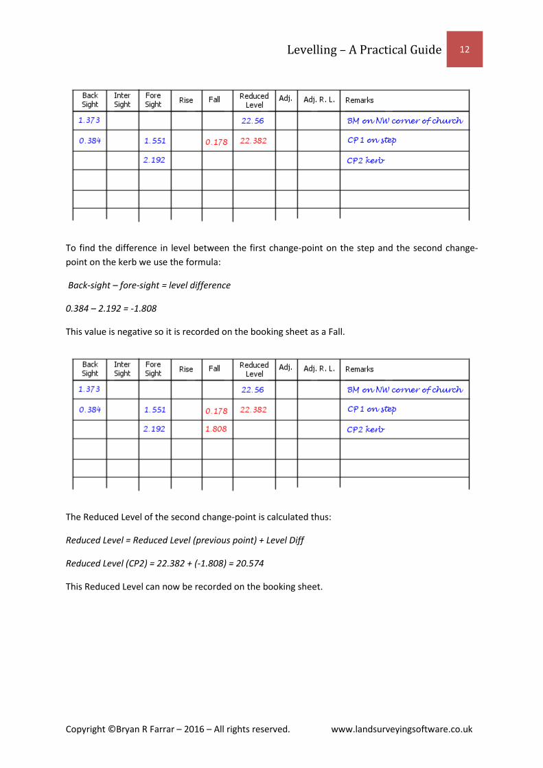
To find the difference in level between the first change-point on the step and the second change-
point on the kerb we use the formula:
Back-sight – fore-sight = level difference
0.384 – 2.192 = -1.808
This value is negative so it is recorded on the booking sheet as a Fall.
The Reduced Level of the second change-point is calculated thus:
Reduced Level = Reduced Level (previous point) + Level Diff
Reduced Level (CP2) = 22.382 + (-1.808) = 20.574
This Reduced Level can now be recorded on the booking sheet.

Levelling – A Practical Guide 13
Copyright ©Bryan R Farrar – 2016 – All rights reserved. www.landsurveyingsoftware.co.uk
The road has levelled out here and the first manhole cover is about 30 paces away so the Surveyor
now sets up the level 15 paces from the staff (which remains at the change-point on the kerb) in the
direction of the manhole cover. The staff is rocked and a back-sight reading of 1.595 is taken and
recorded.
The Assistant now places the staff on the first manhole cover (MH176) and a foresight reading of
1.486 is observed.
Back-sight – fore-sight = level difference

Levelling – A Practical Guide 14
Copyright ©Bryan R Farrar – 2016 – All rights reserved. www.landsurveyingsoftware.co.uk
1.595 – 1.486 = 0.109
This value is positive so it is recorded on the booking sheet as a Rise.
Reduced Level = Reduced Level (previous point) + Level Diff
Reduced Level (MH176) = 20.574 + 0.109 = 20.683
This Reduced Level can now be recorded on the booking sheet.
The second manhole cover is adjacent to the first so we will now, move the level instrument, take a
back-sight to the current staff position and then measure the level of the second manhole cover by
observing an intermediate sight.
So, we now move the level along the level-run in the direction of the final benchmark and set up.
We will keep the distance from the level to the second manhole quite short as we will be observing
an intermediate sight, which doesn’t benefit from the error cancelling effect of a back-sight/fore-
sight. We now observe a back-sight of 1.492 to the staff at MH176 and record the observation.

Levelling – A Practical Guide 15
Copyright ©Bryan R Farrar – 2016 – All rights reserved. www.landsurveyingsoftware.co.uk
The staff is now placed on the second manhole cover (MH177) and an intermediate sight reading of
1.483 observed and recorded.
Back-sight – intermediate sight = level difference
1.492 – 1.483 = 0.009
This value is positive so it is recorded on the booking sheet as a Rise.

Levelling – A Practical Guide 16
Copyright ©Bryan R Farrar – 2016 – All rights reserved. www.landsurveyingsoftware.co.uk
Reduced Level = Reduced Level (previous point) + Level Diff
Reduced Level (MH177) = 20.683 + 0.009 = 20.692
This Reduced Level can now be recorded on the booking sheet.
Now the staff is moved to a third manhole cover (MH178) adjacent to the second and another
intermediate sight of 1.470 observed and recorded.

Levelling – A Practical Guide 17
Copyright ©Bryan R Farrar – 2016 – All rights reserved. www.landsurveyingsoftware.co.uk
Back-sight – intermediate sight = level difference
1.492 – 1.470 = 0.022
This value is positive so it is recorded on the booking sheet as a Rise.
Reduced Level = Reduced Level (previous back-sight) + Level Diff
Reduced Level (MH178) = 20.683 + 0.022 = 20.705
This Reduced Level can now be recorded on the booking sheet.

Levelling – A Practical Guide 18
Copyright ©Bryan R Farrar – 2016 – All rights reserved. www.landsurveyingsoftware.co.uk
Now the staff is moved to a change-point (CP3 - in this case another point on the kerb) further
towards the final benchmark, so that the distance to the back-sight (at MH176) and the level, and
from the level to this new change-point is equal. A foresight reading of 1.513 is observed and
recorded.
Back-sight – fore-sight = level difference
1.492 – 1.513 = -0.021
This value is negative so it is recorded on the booking sheet as a Fall.

Levelling – A Practical Guide 19
Copyright ©Bryan R Farrar – 2016 – All rights reserved. www.landsurveyingsoftware.co.uk
Reduced Level = Reduced Level (previous back-sight) + Level Diff
Reduced Level (CP3) = 20.683 + (-0.021) = 20.662
This Reduced Level can now be recorded on the booking sheet.
The final benchmark, on a gatepost is now in sight so the level is moved to a point half way between
it and the change-point (CP3). A back-sight of 0.443 is observed to CP3 and recorded.

Levelling – A Practical Guide 20
Copyright ©Bryan R Farrar – 2016 – All rights reserved. www.landsurveyingsoftware.co.uk
The staff is now placed vertically so that its base is level with horizontal bar of the benchmark carved
on the gatepost and a foresight taken, the value of which is 1.654. This is recorded on the booking
sheet, along with the location of the benchmark and its known level above mean sea level.
Back-sight – fore-sight = level difference
0.443 - 1.651 = -1.208
This value is negative so it is recorded on the booking sheet as a Fall.

Levelling – A Practical Guide 21
Copyright ©Bryan R Farrar – 2016 – All rights reserved. www.landsurveyingsoftware.co.uk
Reduced Level = Reduced Level (previous back-sight) + Level Diff
Reduced Level (BM on gatepost) = 20.662 + (-1.208) = 19.454
This Reduced Level can now be recorded on the booking sheet.
We have now completed the level-run. We have calculated the Reduced Level of the benchmark on
the gate to be 19.454 and we know the value to be 19.45. There is a difference of 0.004m between
our observed value and the known value and this is called the misclosure.
There are now some checks we must carry out before leaving the site to ensure that we have not
introduced any errors whilst calculating the Rise/Fall and Reduced Level values.

Levelling – A Practical Guide 22
Copyright ©Bryan R Farrar – 2016 – All rights reserved. www.landsurveyingsoftware.co.uk
Step 1
First we calculate the difference between the last calculated Reduced Level and the first Reduced
Level:
19.454 – 22.56 = -3.106
Step 2
We can now check our Rise and Fall values by adding up all of the Rise values (excluding
intermediate sights) and subtracting all of the Fall values (excluding intermediate sights). The
difference should be the same as the difference between Reduced Levels calculated in Step 1:
Sum of the Rises = 0.109
Sum of the Falls = 0.178 + 1.808 + 0.021 + 1.208 = 3.215
Sum of the Rises – Sum of the Falls = 0.109 – 3.215 = -3.106
Step 3
Similarly, the sum of the back-sights should equal the sum of the foresights:
Sum of the back-sights = 1.373 + 0.384 + 1.595 + 1.492 + 0.443 = 5.287
Sum of Foresights = 1.551 + 2.192 + 1.486 + 1.513 + 1.651 = 8.393
Sum of the Backsights – Sum of the Foresights = 5.287 – 8.393 = -3.106
Each of the values calculated in steps 1, 2 and 3 are the same, so our mental arithmetic is correct.
To summarize (where ∑ = “Sum of”):
(∑ Backsights – ∑ Foresights) = (∑ Rises – ∑ Falls) = Last Reduced Level – First Reduced Level
If you are using Knightwood LevelBook to calculate your Rise/Fall and Reduced Level values then
there will be no mental arithmetic errors. However, if booking the results on a booking sheet to be
entered into Knightwood LevelBook back at the office it is advisable to calculate the misclosure value
before leaving the site to ensure that an acceptable level of accuracy has been obtained.
Using the above example level-run we would do this as follows:
Step 1
Calculate the difference in level between our end point and our start point:
BM on Gate – BM on Church = 19.45 – 22.56 = -3.11
Step 2

Levelling – A Practical Guide 23
Copyright ©Bryan R Farrar – 2016 – All rights reserved. www.landsurveyingsoftware.co.uk
Calculate ∑ Backsights – ∑ Foresights
Sum of the Backsights – Sum of the Foresights = 5.287 – 8.393 = -3.106
Step 3
Calculate the misclosure
Misclosure = (Last RL – First RL) – (∑ Backsights – ∑ Foresights)
Misclosure = (-3.11) – (-3.106) = -0.004
In real life it would be unlikely that two benchmarks would be situated so close together, so a more
likely situation would involve the level-run finishing back on the starting point of the benchmark on
the church. In this scenario the level of the last point minus the level of the first point would be
zero. Therefore ∑ Backsights – ∑ Foresights should also equal zero and any difference from this is
the misclosure.
The misclosure should be distributed through the calculated Reduced Levels of each point on the
level-run, adjusting the value as necessary, as is demonstrated in the figure below.
If Knightwood LevelBook had been used to calculate the level-run then the screen would look like
this:

Levelling – A Practical Guide 24
Copyright ©Bryan R Farrar – 2016 – All rights reserved. www.landsurveyingsoftware.co.uk
Finding the Reduced Level of a High Point (Inverted Staff) If you need to determine the level of a point above the ground such as a soffit level of a bridge or
the eaves of a house the measuring staff can be inverted and a reading taken to the inverted staff. It
should still be rocked through the horizontal and the lowest value recorded. However, this value
should be recorded as a negative value and the Rise/Fall values calculated using this negative value.
For instance, in this example:
Rise/Fall = BS – FS
Rise/Fall = 1.500 – (-1.000)
Rise/Fall = 2.500
RLB = RLA + Rise/Fall
RLB = 100.000 + 2.500 = 102.500

Levelling – A Practical Guide 25
Copyright ©Bryan R Farrar – 2016 – All rights reserved. www.landsurveyingsoftware.co.uk
Sources of Errors Below is a table of possible error sources and how they should be minimised.
Error Source Effect Action required
Optical Errors/alignment of the level
Line of sight will deviate from the horizontal, increasing over distance.
Keep back-sight and fore-sight distances as equal as possible. Avoid intermediate sights.
Staff not vertical Staff reading will be too high.
Rock staff slowly through the vertical and record the lowest value.
Mental arithmetic error Calculated values will be wrong.
Use formula (∑ Back-sights - ∑ Fore-sights) = (∑ Rises - ∑ Falls) = Last Reduced Level - First Reduced Level to detect errors. Use Knightwood LevelBook to avoid errors. Avoid intermediate sights.
Reading not recorded correctly
Large misclosure if it is a back-sight or fore-sight. Undetectable if it is an intermediate sight.
Repeat level-run. Try to avoid e.g. 1.677 is easily erroneously recorded as 1.667. Avoid intermediate sights.
Curvature of the Earth Line of sight will deviate from the horizontal, increasing over distance.
Keep distances short.
Tips to remember Be aware of your surroundings and be safe.
Avoid intermediate sights as they are prone to errors.
Keep back-sight and fore-sight distances equal to cancel out line-of-sight errors.
Rock the staff through the vertical and record the lowest reading to ensure correct staff
readings.
Use Knightwood LevelBook to process your field observations to avoid calculation errors,
present your results in a professional manner, and archive your observations electronically.
Try for free – www.landsurveyingsoftware.co.uk