conventional cruise-missile attackandballistic … cruise-missile attackandballistic-missile s...
TRANSCRIPT
Project AIR FORCE
Prepared for the United States Air Force
Approved for public release; distribution unlimited
R
John Stillion
David T. Orletsky
Airbase Vulnerability toConventional Cruise-Missile
and Ballistic-Missile
AttackSTechnology, Scenarios, and U.S. Air Force Responses
The research reported here was sponsored by the United States AirForce under Contract F49642-96-C-0001. Further information maybe obtained from the Strategic Planning Division, Directorate ofPlans, Hq USAF.
The photo of the M-9 missile is from p. 386 (Figure 7.13) of Robert S. Norris, Andrew S.Burrows, and Richard W. Fieldhouse, Nuclear Weapons Databook, Volume V: British,
French, and Chinese Nuclear Weapons (A book by the Natural Resources DefenseCouncil, Inc.), Boulder, CO: Westview Press, 1994. Reprinted by permission. The photo of
the parked fighter aircraft is courtesy of the U.S. Air Force.
RAND is a nonprofit institution that helps improve policy and decisionmaking through research and analysis. RAND® is a registeredtrademark.RAND’s publications do not necessarily reflect the opinionsor policies of its research sponsors.
© Copyright 1999 RAND
All rights reserved. No part of this book may be reproduced in anyform by any electronic or mechanical means (including photocopying,recording, or information storage and retrieval) without permissionin writing from RAND.
Library of Congress Cataloging-in-Publication DataStillion, John.
Airbase vulnerability to conventional cruise-missile and ballistic- missile attacks : technology, scenarios, and U.S. Air Force responses /John Stillion and David T. Orletsky.
p. cm.“Prepared for the U.S. Air Force by RAND’s Project AIR
FORCE.”“MR-1028-AF.”ISBN 0-8330-2700-X1. Air bases—Security measures—United States. 2. Cruise
missile defenses—United States. 3. Ballistic missile defenses—United States. 4. United States. Air Force—Security measures. I. Orletsky, David T., 1963 - . II. United States. Air Force. III. Project AIR FORCE (U.S.). UG634.49.S75 1999358.4 ' 17 ' 0973—dc21 99-12338
CIP
Published 1999 by RAND1700 Main Street, P.O. Box 2138, Santa Monica, CA 90407-2138
1333 H St., N.W., Washington, D.C. 20005-4707RAND URL: http://www.rand.org/
To order RAND documents or to obtain additional information,contact Distribution Services: Telephone: (310) 451-7002;
Fax: (310) 451-6915; Internet: [email protected]
iii
PREFACE
In fiscal year 1997, under the sponsorship of the Air Force AssistantDeputy Chief of Staff for Air and Space Operations and the Air ForceDirector of Strategic Planning, RAND’s Project AIR FORCE Strategyand Doctrine Program began a two-year effort to explore the role ofair and space power in future conflicts. The primary objective of thestudy was to explore the prospects for developing a construct for airand space power that capitalizes on forthcoming air and space tech-nologies and associated concepts of operation (CONOPS); that is ef-fective against adversaries with diverse economies, cultures, politicalinstitutions, and military capabilities; and that offers an expansiveconcept of air and space power across the entire spectrum of con-flict.
Under this broader study, the research team investigated the possi-bility that future adversaries might be able to mount effective missileattacks on U.S. Air Force (USAF) main operating bases in critical re-gions. Both emerging technologies and the proliferation of existingcapabilities will give adversaries pursuing anti-access strategies a va-riety of new options against U.S. airbases, ports, troop concentra-tions, and ships at sea.
This report is not intended to assess the relative vulnerabilities ofthese various force elements and facilities. Rather, its purpose is tohelp the USAF address a potential vulnerability of its in-theaterbases. The proliferation of Global Positioning System (GPS) guidanceand submunition warhead technologies could make highly accurateattacks possible against USAF aircraft on parking ramps at thesebases. If such attacks are feasible, the current USAF operational con-
iv Airbase Vulnerability
cept of high-tempo, parallel strikes from in-theater bases could beput in jeopardy. It is for this reason that this operational problemwas deemed relevant—indeed central—to the purposes of the overallstudy on the future of airpower. The research documented in thisreport concluded that these guidance and munition technologiescould, in fact, put USAF bases at serious risk. We recommend thatothers with expertise in land and naval operations conduct similarassessments of their vulnerabilities to these and other new tech-nologies. The report describes the threat technologies and concept ofoperation in detail, then explores both short- and long-term re-sponses to these threats.
This report should be of interest to USAF planners and operators inthe Air Staff, Major Command, and Numbered Air Force Headquar-ters and operational units, as well as to students of air and spacepower in the other services and the broader defense community.
Project AIR FORCE
Project AIR FORCE, a division of RAND, is the Air Force federallyfunded research and development center (FFRDC) for studies andanalysis. It provides the Air Force with independent analyses of pol-icy alternatives affecting the development, employment, combatreadiness, and support of current and future air and space forces.Research is performed in four programs: Aerospace Force De-velopment; Manpower, Personnel, and Training; Resource Man-agement; and Strategy and Doctrine.
v
CONTENTS
Preface ......................................... iii
Figures ......................................... vii
Tables.......................................... ix
Summary ....................................... xi
Acknowledgments................................. xix
Abbreviations and Acronyms......................... xxi
Chapter OneINTRODUCTION .............................. 1Purpose ..................................... 2Organization.................................. 3
Chapter TwoEMERGING THREAT TECHNOLOGIES .............. 5The Eagles in Their Nests ........................ 5Potential Ballistic- and Cruise-Missile Threats ......... 7Improving Accuracy with GPS ..................... 8
Ballistic Missiles.............................. 9Cruise Missiles............................... 10
Improving Lethality ............................ 11The Low, Slow Killer—A Cheap and Effective Anti-Airfield
Cruise Missile ............................. 15
Chapter ThreeILLUSTRATIVE SCENARIO AND IMPLICATIONS ....... 19A New War in the Gulf ........................... 19Missile Attacks Against USAF Assets................. 22
vi Airbase Vulnerability
Attacking Aircraft............................. 23Attacking Tent Cities .......................... 25
In Sum ...................................... 27
Chapter FourDEFENSIVE RESPONSES TO AN ENEMY-MISSILE
THREAT ................................. 29Passive Defenses............................... 30
Fixed Hardened Shelters ....................... 30Deployable Shelters........................... 32Dispersed Aircraft Parking ...................... 35Dispersed Operations ......................... 39Alternative Dispersed-Basing Concept ............. 41Concluding Remarks .......................... 41
Active Defenses................................ 42Short-Term Active Defenses..................... 43Medium- and Long-Term Active Defenses .......... 46
Chapter FiveSTAND-OFF OPTIONS .......................... 49Short-Term Stand-Off Options .................... 49Long-Term Stand-Off Options..................... 54
Chapter SixCONCLUSIONS................................ 59
AppendixA. DAMAGE CALCULATION FOR PARKED AIRCRAFT ..... 61B. SORTIE-RATE MODEL .......................... 81C. FAST, LONG-RANGE-ATTACK AIRCRAFT ............ 85
Bibliography..................................... 95
vii
FIGURES
2.1. Parking Ramps at Shaikh Isa, Bahrain, Early 1991 .... 62.2. Lethal Area of 1-Pound Submunition Versus Unitary
Warheads of the Same Weight .................. 122.3. Comparison of Warhead Lethal Radii for a Typical
Ballistic Missile and the Two Postulated Cruise-Missile Candidate UAVs ...................... 14
3.1. Possible USAF Deployment Bases and PostulatedIranian Missile Ranges ....................... 21
3.2. Tent City at Prince Sultan Air Base (Al Kharj), 1996 ... 264.1. F-117 Fighter Being Towed into a Concrete Hardened
Aircraft Shelter ............................. 324.2. Missiles Required to Attack Dhahran Parking Ramps
With and Without Shelters..................... 344.3. Additional Aircraft Parking-Ramp Geometry of
Hardstands Built Outward Radially from the Base toMaximize Weapon Requirements ............... 36
4.4. Weapons Needed to Attack a Fighter Wing As aFunction of Distance Between Parking Spots ....... 37
4.5. Fields of Fire Around a Theater Operating Base, froman Anti–Cruise Missile Gun Tower .............. 46
5.1. Stand-Off and Close-In Deployment Bases withPossible Iranian Missile Ranges ................. 50
5.2. PGM Strikes As a Function of Range for a PostulatedUSAF Theater Attack Force .................... 52
5.3. Areas That Current 500-Knot Fighter Forces CouldReach from Four “Secure” Bases ................ 55
5.4. Areas of the World a Force of 1,000-Knot AircraftCould Reach from Four Secure Bases............. 56
viii Airbase Vulnerability
A.1. Diagram of Dhahran Airbase ................... 63A.2. Layout of Calculation Blocks ................... 65A.3. Diagram for Edge-Effects Analysis ............... 66A.4. Block Terminology .......................... 67A.5. Circular Patterns Superimposed on Calculation
Blocks for Same-Block and Different-BlockCalculations ............................... 69
A.6. Area Covered by Weapons Aimed at NeighboringBlocks.................................... 70
A.7. Calculation Based on Coverage of Center Point ofBlock .................................... 73
A.8. Diagram for Calculation of Neighboring-BlockCoverage.................................. 75
A.9. Geometry of Neighboring-Block Calculation ....... 75C.1. Operational Concept for a Long-Range Supersonic
Bomber Force.............................. 87C.2. Tankers Required per Bomber Sortie As a Function of
Unrefueled Bomber Range .................... 88C.3. Payload Versus Bomber Weight ................. 90C.4. Bomber Sorties and Tanker Capacity Required As a
Function of Bomber Payload ................... 93
ix
TABLES
2.1. Examples of UAV Airframes That Could Be Convertedinto Effective and Relatively Inexpensive CruiseMissiles................................... 16
3.1. Parking-Ramp Dimensions at Possible USAFDeployment ............................... 23
3.2. Least-Cost 0.9-Pk Missile Requirements........... 24A.1. Number of Ballistic and Cruise Missiles of a Given
Type Required to Attack Each Ramp at FourSouthwest Asia Bases ........................ 79
B.1. Average Time Required for VariousTurnaround-Time Tasks ...................... 83

xi
SUMMARY
During the 43-day Gulf War, the U.S. Air Force (USAF) flew nearly70,000 sorties, attacked over 28,000 targets, shot down 36 Iraqi air-craft, disrupted Iraqi command and control and transportation sys-tems, and directly attacked the Iraqi army in Kuwait, destroyingmany of its vehicles and damaging its morale before the ground of-fensive began. All of this damage was achieved at the cost of just 14aircraft, which were lost to ground-based air defenses; none were lostin air-to-air combat. The USAF plans to build on its success inOperation Desert Storm by deploying increasing numbers of stealthyaircraft and precision-guided munitions (PGMs), supported by amuch more capable battle-management system, to fight the nextwar.
However, the USAF is not the only organization to have drawnlessons from Operation Desert Storm. Potential adversaries are likelyto expend considerable time, energy, and resources on ensuring thatthe USAF does not make such a large contribution to victory at solow a cost in a future conflict. The research reported here confrontsthis possibility and examines ways of dealing with it.
PURPOSE AND APPROACH
Other RAND research has explored how potential adversaries coulduse asymmetric strategies, special operations forces, terrorists,information attacks, and weapons of mass destruction to degrade or
xii Airbase Vulnerability
eliminate USAF combat capability during a future conflict.1 Thisreport presents yet another strategy whereby a clever and competentadversary could attempt to interfere with USAF combat operations ifthe USAF sticks to the operational concepts that served it so wellduring Operation Desert Storm. It examines the following questions:
• How could potential adversaries use readily available commer-cial and military technology to modify conventionally armedcruise and ballistic missiles to effectively attack USAF aircraft onthe ground, at theater operating bases?
• How technically advanced must an adversary be to successfullysuppress USAF operations from theater operating bases?
• What options (new operational concepts, material, equipment,etc.) exist for the USAF to minimize the impact of conventionalcruise- and ballistic-missile attacks on theater operating bases,both in the near term and long term?
EMERGING THREAT TECHNOLOGY
Ballistic and cruise missiles must be accurate to be militarily effec-tive. Although many countries around the world deploy ballisticmissiles similar to those used by Iraq in 1991, these weapons havelimited utility against military targets. Several countries, includingIraq and Iran, have used them in combat—but only as terrorweapons.2 Technological sophistication is required for an accurateand robust (militarily suitable) cruise missile, which means that onlya few nations currently possess inventories, and only the UnitedStates has used cruise missiles in combat since the end of World WarII. Global Positioning System (GPS) guidance devices provide a fairlycheap and effective way of improving both ballistic- and, especially,cruise-missile guidance. This technology could be used to improve
______________1See David Shlapak and Alan Vick, “Check Six begins on the ground”: Responding tothe Evolving Ground Threat to U.S. Air Force Bases, Santa Monica, Calif.: RAND,MR-606-AF, 1995; Maurice Eisenstein, “The Use of Weapons of Mass Destruction byTerrorists Against Air Bases,” unpublished RAND research; Brian Chow, Air ForceOperations in a Chemical and Biological Environment, Santa Monica, Calif.: RAND,DB-189/1-AF, 1998.2Terror weapons are weapons designed specifically to cause damage, casualties, andfear within the targeted civilian population.
Summary xiii
the accuracy of existing ballistic missiles to about 100 meters andallow almost all nations to obtain the accurate cruise missiles that,until now, have been reserved for technologically advanced societies.
However, improved missile accuracy is not enough to make ballisticand cruise missiles both militarily effective and affordable weaponsagainst parked aircraft. Submunitions are far more efficient againstsoft targets susceptible to blast or fragmentation damage than areunitary warheads of the same weight. The lethal area of a cruisemissile with a 75-pound payload against aircraft in the open is aboutthree times greater when using a submunition warhead than whenusing a unitary warhead. This advantage increases with increasingpayload. An 1,100-pound M-9 ballistic-missile warhead coversalmost eight times the area when using a submunition warhead thanwhen using a unitary warhead.3 The combination of increasedaccuracy from GPS guidance and increased warhead efficiency iswhat decreases the number of missiles required to attack USAFairbases from hundreds to dozens.
A potential asymmetric strategy considered in this report is the use ofsmall, slow cruise missiles to “slip under” the current USAF radarumbrella. The term “cruise missile” simply refers to an unmannedaircraft designed to fly a one-way attack mission. The cruise missilesconsidered here are significantly different from the high-perfor-mance fighter-size targets USAF air defense systems were designedto counter during the Cold War. Cruising at about 70 knots, thesesmall aircraft would be difficult for current USAF air defense systemsto detect. Surveillance and tracking radars designed during the ColdWar (e.g., those on F-15s, F-16s, and Airborne Warning and ControlSystem [AWACS]) took advantage of the high speed of Soviet combataircraft to simplify the task of sorting attacking aircraft from ground-vehicle clutter merely by ignoring potential targets moving slowerthan about 80 knots. Some of the systems have the capability to de-tect and track slower targets, but only in narrow sectors and for shortperiods of time before the number of potential targets exceeds thesystem’s data-processing and display capabilities.
______________3These calculations assume a 20-foot lethal radius for a 1-pound submunition andthat 75 percent of warhead weight is devoted to submunitions, with the remainder de-voted to a frame and dispensing mechanism.
xiv Airbase Vulnerability
Surface radars are less affected by ground clutter than are airborneradars but suffer from limited line of sight against low-flying targets.Patriot and AEGIS4 could acquire and track a slow-moving cruisemissile, but only above the radar horizon—less than 20 miles for acruise missile flying at 100 to 130 feet. Unless the United States de-ploys huge numbers of ground-based radars to a future theater con-flict, most cruise missiles will go undetected by current U.S. air de-fense systems.
OPERATIONAL IMPACT
We posit a simple illustrative scenario to explore the impact GPS-guided cruise and ballistic missiles equipped with submunitionpayloads might have on current USAF theater air operations. In ourscenario, Iran uses an Iraqi succession crisis turned civil war as anopportunity to invade southern Iraq. The United States responds ina variety of ways, including deploying USAF combat aircraft to thefollowing bases on the Arabian peninsula: Dhahran, Doha, RiyadhMilitary, and Al Kharj.
These bases have a total of 14 potential parking areas ranging in sizefrom 600 × 300 feet to 9,000 × 900 feet. The total area of the parkingramps at these bases is over 44 million square feet—the equivalent ofalmost 1,000 football fields. These bases can accommodate a hugenumber of combat aircraft and an intense aerial-port operation.However, the number of GPS-guided, submunition warhead cruisemissiles and ballistic missiles required to attack this huge area issurprisingly small, assuming a 20-foot lethal radius for the 1-poundsubmunitions employed and standard USAF aircraft-parking proce-dures. A 0.9 Pk (probability of kill) against all aircraft on the parkingramps of these four bases could be achieved with 30 GPS-guided M-9and 30 M-18 ballistic missiles, and 38 small GPS-guided cruisemissiles, at an estimated cost of about $101 million.
______________4AEGIS is a totally integrated shipboard weapon system that combines computers,radars, and missiles to provide a defense umbrella for surface shipping. The system iscapable of automatically detecting, tracking, and destroying airborne, seaborne, andland-launched weapons. Joint Chiefs of Staff, Department of Defense Dictionary ofMilitary Terms, Washington, D.C.: Joint-Pub 1-02, March 23, 1994, pp. 6–7.
Summary xv
Attacking the tent cities at all four bases and a Patriot or theater high-altitude air defense (THAAD) radar at each requires an additional 40ballistic missiles and 8 cruise missiles, raising the total cost to about$163 million—about the cost of four Russian Su-27 export-versionfighters. The effect on USAF sortie generation of destroying a largenumber of aircraft, living quarters, most personal equipment, andsome work centers while creating widespread foreign-object damagewould be devastating.
POSSIBLE USAF RESPONSES
To reduce the vulnerability of deployed forces, the USAF could take avariety of actions over the next few years. These actions fall intothree basic categories: passive defenses, active defenses, and disper-sal.
Passive defenses include constructing hardened aircraft shelters andliving facilities at likely deployment bases; acquiring deployableshelters, for both aircraft and personnel, capable of withstandingsubmunition impact; and constructing additional parking-rampspace to allow increased dispersal. These measures would compli-cate an adversary’s targeting problem and increase the number ofweapons required to achieve a given level of damage.
All of these measures could be effective against GPS-guided cruise-and ballistic-missile attacks, but have potentially serious drawbacks.Hardened shelters and additional parking ramps are expensive, time-consuming construction projects that require the USAF to correctlyanticipate—years in advance—where it will fight the next war. De-ployable shelters allow more-flexible operations, but significantly in-crease the wing’s airlift requirements.
Short-term active defenses against the small, slow cruise-missilethreat could include relatively low-tech, simple measures such asputting machine-gun teams with night-vision goggles in towers sur-rounding USAF operating bases or deploying radar-guided guns.
Another relatively short-term alternative available to the USAF is todisperse its operations to a large number of highway landing strips tocomplicate an adversary’s targeting problem. This option has thepotential to defeat the missile threat but, again, carries significant
xvi Airbase Vulnerability
potential costs, especially for sortie-generation activities. Sortie ratewould not necessarily be reduced by dispersed operations, given theeconomies-of-scale considerations in maintenance and force pro-tection, but would require more personnel to achieve the samenumber of sorties (all other things being equal—range to target,availability of munitions, etc.). In addition, an adversary with accessto effective human intelligence (HUMINT) or satellite capabilitycould locate and attack USAF units at these dispersed locations.
The Expeditionary Air Force (EAF) concept also must be consideredwhen formulating basing operations and vulnerability to missile at-tack. This concept emphasizes the ability to rapidly deploy any-where in the world, which raises two issues for defense planning:First, little support will exist to build additional infrastructure(shelters, additional ramp space, etc.) at potential deployment basesthat could reduce the impact of airbase attack. Second, since theEAF must travel light to deploy a warfighting package quickly any-where in the world, little flexibility will exist to transport items thatwould provide protection or facilitate recovery from such attacks.
POTENTIAL LONG-TERM SOLUTIONS
If the USAF could conduct its theater air campaigns from a few se-cure bases with assured access,5 many of the issues discussed in thisreport could be avoided. Hardened facilities and advanced missiledefenses could be constructed prior to the start of hostilities. Al-though a detailed cost analysis was beyond the scope of this work,building a robust passive and active defense system at only a few se-lected bases should limit the total expense.
To achieve the goal of operating anywhere in the world from a fewsecure, hardened, fixed bases with guaranteed access, the USAFwould need to develop operational concepts for longer ranges.Crew-fatigue considerations limit aircraft with 500-knot cruisespeeds to ranges of about 2,000 nautical miles (nmi) for sustainedoperations. An aircraft with a 1,000-knot cruise speed could covervirtually the entire inhabited land surface of the Earth, except for the
______________5Assured access means basing in the United States or on the territory of very close al-lies, such as the United Kingdom, who typically support U.S. actions.
Summary xvii
southern tips of Africa and South America, by operating from foursecure hardened bases: Guam, near Anchorage, Miami, and London.
A total inventory of approximately 80 to 105 Mach 2 bombers withthe following specifications could deliver enough PGMs (about 560tons per day) to replicate the USAF Desert Storm effort:
• a weight of 290,000 to 350,000 pounds
• an unrefueled range of 3,250 nmi
• a payload of 15,000 to 20,000 pounds.
This force could attack targets almost anywhere in the world whileoperating from well-protected, permanent bases in the United Statesand the United Kingdom.

xix
ACKNOWLEDGMENTS
The authors thank their RAND colleague and project leader, AlanVick, for suggesting the topic and providing guidance and assistancethroughout the effort. We are grateful to LtCol Julie Neumann, whoserved as action officer for the project. We also thank our RAND col-leagues Irving Lachow and John Pinder for their assistance. TimBonds and David Shlapak reviewed a draft of this document. Manyof their suggested changes have been incorporated here, and haveimproved the substance and style of this document. Finally, weextend our deepest and most grateful appreciation to our editor,Marian Branch. Once again, she has worked the magic we havebecome so accustomed to, significantly improving the quality of thismanuscript.

xxi
ABBREVIATIONS AND ACRONYMS
ABM anti–ballistic missile (system)
AEF Air Expeditionary Force
AFB Air Force Base
AFH Air Force Handbook
APOD aerial port of debarkation
AWACS Airborne Warning and Control System
BM ballistic missile
C/A coarse acquisition (navigation signal—GPS)
CEP circular error probable
CM cruise missile
CONOPS Concept of operations
CRAF Civilian Reserve Airlift Fleet
CSS Chinese surface-to-surface (missile)
DAFIF Digital Aeronautical Flight Information File
DE directed energy
DGPS differential Global Positioning System
DOPS Defense Intelligence Agency Outline PlottingSystem
EAF Expeditionary Air Force
FOB Forward Operating Base
FOD foreign-object damage
xxii Airbase Vulnerability
FT flight time
GPS Global Positioning System
GT ground time
GWAPS Gulf War Air Power Survey
HE high explosive
HUMINT human intelligence
INS inertial navigation system
IOC initial operational capability
IR infrared
IRSTS Infra-Red Search and Track System
ISR intelligence, surveillance, reconnaissance
JDAM Joint Direct Attack Munition
JSTARS Joint Surveillance, Targeting, and ReconnaissanceSystem
L/D lift divided by drag
MLRS multiple-launch rocket system
MOB Main Operating Base
MT maintenance time
MTW major theater warfare
NATO North Atlantic Treaty Organization
PGM precision-guided munition
Pk probability of kill
PRC People’s Republic of China
RAF Royal Air Force (United Kingdom)
rms root mean square
SA Selected Availability
SAM surface-to-air missile
SDPR System Design and Performance Requirements
SEAD suppression of enemy air defense
SHORAD short-range air defense
Acronyms xxiii
SOF special operations force
SPS Standard Positioning Service (GPS)
SR sortie rate
SRBM short-range ballistic missile
STTO start, taxi, take off
SWA Southwest Asia
TAT turnaround time
TERCOM TERrain COntour Matching
THAAD theater high-altitude air defense
TLE target-location error
UAE United Arab Emirates
UAV unmanned aerial vehicle
USAF United States Air Force

1
Chapter One
INTRODUCTION
The tremendous success of U.S. Air Force (USAF) operations againstthe Iraqi military during the 1991 Gulf War was a stunning achieve-ment. Videotaped images of laser-guided bombs being dropped fromUSAF stealth aircraft with impunity onto targets deep inside Iraqcontain the seeds of both the popular perception of how the war wasfought and the “lessons learned” the USAF took away from the war.During the course of the 43-day war, the USAF flew 69,406 sorties,attacked 28,295 targets, shot down 36 Iraqi aircraft, disrupted Iraqicommand and control and transportation systems, and directlyattacked the Iraqi army in Kuwait, destroying many of its vehicles andseverely damaging its morale before the ground offensive began. Allof this was achieved at the cost of just 14 aircraft, which were lost toground-based air defenses, not in air-to-air combat.1
The USAF’s success in Operation Desert Storm changed the way mili-tary commanders and the general public view airpower in particularand modern warfare in general. The public expectation is now thatthe USAF could attack almost any target at any time and effectivelydestroy it, with little risk to U.S. military personnel or to noncombat-ants on the ground. As well, the war left the impression that, whilecertain aspects of USAF operations such as bomb-damage assessmentcould be refined to improve the efficiency of operations, the basicconcept of deploying large numbers of combat aircraft and supportpersonnel to vulnerable bases within a few hundred nautical miles of
______________1Eliot A. Cohen, ed., Gulf War Air Power Survey [GWAPS], Vol. V: A StatisticalCompendium and Chronology, Washington, D.C.: U.S. Government Printing Office, 1993,pp. 316, 418, 651–654.
2 Airbase Vulnerability
enemy territory should continue to be the blueprint for future USAFtheater air campaigns. However, these operations were conductedagainst an adversary who lacked the means, will, skill, and vision toattempt to attack and disrupt USAF aircraft and operations wherethey are most vulnerable—at their fixed operating bases. Next timeout, the USAF may not be so lucky.
In fact, the air campaign seems to have achieved so much at so small acost that potential adversaries are likely to expend substantial time,energy, and resources to ensure that the USAF does not make such alarge contribution to victory at so low a cost in a future conflict.
PURPOSE
Other RAND research has explored how potential adversaries coulduse asymmetric strategies, special operations forces, terrorists,information attacks, and weapons of mass destruction to degrade oreliminate USAF combat capability during a future conflict.2 Thisreport presents yet another way in which a clever and competentadversary could attempt to interfere with USAF combat operations ifthe USAF sticks to the operational concepts that served it so wellduring Operation Desert Storm: modifying cruise and ballisticmissiles to attack USAF aircraft on the ground.
The report examines the following questions:
• How could potential adversaries use readily available commercialand military technology to modify conventionally armed cruiseand ballistic missiles to effectively attack USAF aircraft on theground, at theater operating bases?
• How technically advanced must an adversary be to successfullysuppress USAF operations from theater operating bases?
______________2See David Shlapak and Alan Vick, “Check Six begins on the ground”: Responding to theEvolving Ground Threat to U.S. Air Force Bases, Santa Monica, Calif.: RAND,MR-606-AF, 1995; Maurice Eisenstein, “The Use of Weapons of Mass Destruction byTerrorists Against Air Bases,” unpublished RAND research; Brian Chow, Air ForceOperations in a Chemical and Biological Environment, Santa Monica, Calif.: RAND, DB-189/1-AF, 1998.
Introduction 3
• What options (new operational concepts, material, equipment,etc.) exist for the USAF to minimize the impact of conventionalcruise- and ballistic-missile attacks on theater operating bases,both in the near term and long term?
The answers presented here are speculative. The analysis is based onpotentially available technologies and an understanding of USAFoperations and is intended to expose a potential vulnerability thatcould be exploited by future adversaries. Since many of the weaponsdiscussed in this document would appear to have shorter and lesscostly design and production cycles than USAF aircraft have, thesethreats should be considered prior to acquiring aircraft. Throughoutthis document, we use open source material and simple calculations todevelop a potentially serious threat to USAF aircraft that manyconceivable adversaries could institute.
The Expeditionary Air Force (EAF) concept also must be consideredwhen formulating basing operations and vulnerability to missile at-tack. This concept emphasizes the ability to rapidly deploy anywherein the world, which raises two issues for defense planning: First, littlesupport will exist to build additional infrastructure (shelters,additional ramp space, etc.) that could reduce the impact of airbaseattack at potential deployment bases. Second, since the EAF musttravel light to deploy a warfighting package quickly anywhere in theworld, little flexibility will exist to transport items that would provideprotection or facilitate recovery from such attacks.
ORGANIZATION
Chapter Two describes how existing, readily available technologiescould enable a future regional competitor to build a cheap, accurate,and effective cruise- and ballistic-missile force to attack USAF aircraftwhere and when they are most vulnerable—on the ground at theateroperating bases. Chapter Three presents a scenario to illustrate howan adversary might employ conventional cruise and ballistic missilesto attack USAF theater operating bases, and the potential impact theseattacks might have on USAF operations. Chapter Four describesseveral short- to medium-term actions the USAF could take to counterthe conventional cruise- and ballistic-missile threat. Examples of theseactions include increased efforts, both active and passive, to defend
4 Airbase Vulnerability
USAF theater operating bases from missile attack. Chapter Fivedescribes a new short-term operational concept that could allow theUSAF to operate effectively in the face of our postulated threat. Inaddition, it outlines a longer-term strategy the USAF could adopt: Bydramatically increasing the speed and/or range of its ground attackaircraft, the USAF could minimize its vulnerability to conventionalmissile attacks. This improvement would allow the USAF to conducta sustained air campaign against targets almost anywhere in theworld from a handful of well-defended bases located on U.S. soil orcontrolled by the United States’ most reliable allies. Chapter Sixpresents conclusions. Appendix A presents additional data andassumptions we used to model adversary missile requirements.Appendix B presents the assumptions and equations that form thebasis of our sortie-rate-generation model, which informs the analysisof Appendix C. Appendix C gives some of the technical details of onepossible long-range-attack-aircraft–weapons combination.
5
Chapter Two
EMERGING THREAT TECHNOLOGIES
“The large ground organization of a modern air forceis its Achilles’ heel.”
Basil Henry Liddell Hart, Thoughts on War, 1944
THE EAGLES IN THEIR NESTS
The notion that military aircraft are most vulnerable when they are onthe ground is nothing new. Throughout World War II, both sidesused surprise air attacks, resistance units, special operations forces,and even nighttime naval bombardment to attack parked aircraft. Insome instances, such as the Japanese air attack on Pearl Harbor; theinitial German air assaults on the Polish, Dutch, Belgian, French, andRussian air forces; and the British long-range desert group operationsagainst Axis airfields in North Africa,1 spectacular results wereachieved.
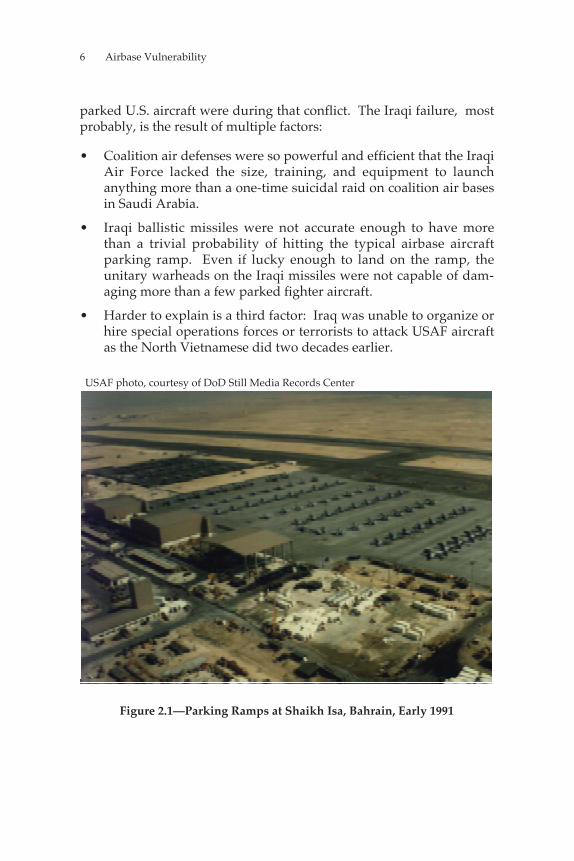
The Iraqis failed to launch a concerted campaign to attack USAF air-craft at their bases during the 1991 Gulf War. The photograph inFigure 2.1 shows just how wide open [literally] and vulnerable many
______________1For a detailed and fascinating account of these little-known operations, see Alan Vick,Snakes in the Eagle’s Nest: A History of Ground Attacks on Air Bases, Santa Monica, Calif.:RAND, MR-553-AF, 1995, Chapter Four. Obviously, the authors have borrowed theexcellent imagery evoked by the title of Alan Vick’s work in titling this section of thechapter.
6 Airbase Vulnerability
parked U.S. aircraft were during that conflict. The Iraqi failure, mostprobably, is the result of multiple factors:
• Coalition air defenses were so powerful and efficient that the IraqiAir Force lacked the size, training, and equipment to launchanything more than a one-time suicidal raid on coalition air basesin Saudi Arabia.
• Iraqi ballistic missiles were not accurate enough to have morethan a trivial probability of hitting the typical airbase aircraftparking ramp. Even if lucky enough to land on the ramp, theunitary warheads on the Iraqi missiles were not capable of dam-aging more than a few parked fighter aircraft.
• Harder to explain is a third factor: Iraq was unable to organize orhire special operations forces or terrorists to attack USAF aircraftas the North Vietnamese did two decades earlier.
USAF photo, courtesy of DoD Still Media Records Center
Figure 2.1—Parking Ramps at Shaikh Isa, Bahrain, Early 1991
Emerging Threat Technologies 7
Regardless of the reasons for the lack of Iraqi airbase attacks, there islittle doubt that an adversary who could successfully mount such at-tacks would present a difficult challenge. The Iraqis, and other re-gional military powers who believe they may someday confront U.S.airpower in a crisis or conflict, are almost certainly searching forinexpensive but effective ways to enhance their capability to attackUSAF assets where they are most vulnerable—on the ground.
In the rest of this chapter, we explain how a powerful regional com-petitor could combine readily available ballistic-missile, unmannedaerial vehicle (UAV), Global Positioning System (GPS), and submuni-tion warhead technologies to produce a variety of accurate, effective,and inexpensive missiles capable of devastating attacks on USAFaircraft parked on open ramps. First, we discuss the cruise- andballistic-missile threats and enhancements that could be incorporatedto improve accuracy and lethality. We then discuss thepotential effectiveness of these weapons against USAF aircraft.
POTENTIAL BALLISTIC- AND CRUISE-MISSILETHREATS
Ballistic and cruise missiles were first used in combat by the Germansduring the last year of World War II. Since then, ballistic missiles havebeen produced in many countries and purchased by many more.2Ballistic missiles were used extensively by both sides in the Iran-IraqWar during the 1980s, and most recently by Iraq in the 1991 Gulf Waragainst targets in Israel and Saudi Arabia. For the most part, the Scudmissiles used in these recent conflicts differed little from their GermanV-2 ancestors: They had about the same range, unitary high-explosivepayload, and accuracy.
This lack of refinement meant that they could attack the same type oflarge-area targets—mostly cities—that the German missiles had beenused against. In the 1991 Gulf War, Scud attacks against cities could
______________2The following countries have ballistic missiles that can deliver at least a 500-kilogram(kg) payload to a target at a 500-kilometer (km) range: Brazil, People’s Republic ofChina (PRC), Egypt, India, Iran, Israel, Japan, North Korea, Libya, Pakistan, SaudiArabia, South Africa, Spain, Syria, Taiwan, and Zaire. See The Nonproliferation Review,Spring–Summer 1995, Vol. 2, No. 3, pp. 203–206. France, Russia, the United Kingdom,and the United States also possess missiles with at least this capability.
8 Airbase Vulnerability
have had important political ramifications (e.g., bringing Israel intothe conflict) and caused the coalition to expend significant resources indeploying additional Patriot missile batteries and hunting mobileScud launchers in the desert wastes of Iraq. However, these indirecteffects were far too small to alter the overall military outcome. To bemilitarily effective, ballistic missiles must be far more accurate andhave much more efficient warheads than were the Scuds employed byIraq in 1991.
In contrast to the relatively wide proliferation of ballistic missiles sincethe end of World War II, land-attack cruise missiles have been de-ployed and used in combat by only one nation—the United States.The primary reason for this exclusivity is that only the United Stateshad the technical capability and financial resources to solve theproblems associated with accurate cruise-missile navigation.
IMPROVING ACCURACY WITH GPS
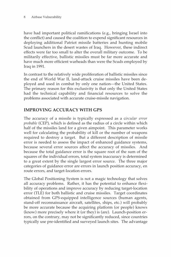
The accuracy of a missile is typically expressed as a circular errorprobable (CEP), which is defined as the radius of a circle within whichhalf of the missiles land for a given aimpoint. This parameter workswell for calculating the probability of kill or the number of weaponsrequired to destroy a target. But a different description of missileerror is needed to assess the impact of enhanced guidance systems,because several error sources affect the accuracy of missiles. Andbecause the total guidance error is the square root of the sum of thesquares of the individual errors, total system inaccuracy is determinedto a great extent by the single largest error source. The three majorcategories of guidance error are errors in launch position accuracy, enroute errors, and target-location errors.
The Global Positioning System is not a magic technology that solvesall accuracy problems. Rather, it has the potential to enhance flexi-bility of operations and improve accuracy by reducing target-locationerror (TLE) for both ballistic and cruise missiles. Target coordinatesobtained from GPS-equipped intelligence sources (human agents,stand-off reconnaissance aircraft, satellites, ships, etc.) will probablybe more accurate because the acquiring platform (or people) knows(know) more precisely where it (or they) is (are). Launch-position er-rors, on the contrary, may not be significantly reduced, since countriestypically use pre-identified and surveyed launch sites. The advantage
Emerging Threat Technologies 9
of using GPS is that it enables more-flexible launch operations to beconducted. Missiles can be accurately launched from anywhere,including offshore platforms, making the launcher more difficult toengage. Another advantage that GPS provides to both types ofmissiles is a consistent coordinate system, which eliminatestransformation errors that can accrue as coordinates are switched fromone grid to another.
Because the two missiles have different characteristics, primarily timeof flight, the addition of GPS guidance3 enhances the accuracy ofballistic and cruise missiles in different ways, discussed in the follow-ing two subsections.
Ballistic Missiles
Errors in the boost and reentry phases of Third World ballistic missilesarise primarily from factors such as variance between commands andactual engine cutoff and aerodynamic forces during reentry. Theseerrors will be virtually unaffected by GPS assistance. The guidancesystem can send precise engine-cutoff information, but if the enginesare not sufficiently advanced to shut down at precisely the rightmoment, the missile accuracy will not be significantly improved.
Compensating for errors arising from aerodynamic forces duringreentry requires that reentry vehicles be equipped with control sur-faces or thrusters to correct for wind drift; most existing short-rangeballistic missiles (SRBMs) lack these systems. As a result, adding GPSguidance to a Scud missile improves accuracy by only about 20 per-cent (bringing the CEP to about 600 meters). In contrast, an advancedSRBM, such as the Chinese M-9, which has warhead-control thrusters,could achieve CEPs in the neighborhood of 150 to 200 meters,
______________3GPS guidance as used in this document means integrated GPS–inertial navigation system(INS) guidance. Inertial navigation systems use gyroscopes to compute position and,therefore, the accuracy of the computed position is inversely related to the time of flight.An integrated GPS–INS system updates the inertially computed position with GPSinformation. Therefore, the positional accuracy is independent of time of flight. Theintegrated GPS–INS system prevents the defender from spoofing the system byjamming the GPS signal in the neighborhood of the target.
10 Airbase Vulnerability
depending on the accuracy of the GPS signal used (SPS, C/A, orDGPS).4
Cruise Missiles
Unlike ballistic missiles, whose flight times are measured in minutes,long-range cruise missiles can take several hours to reach their targets.Long flight times within the atmosphere, and the attendant largeeffect of unpredictable winds on the missile’s course, have been themajor guidance problem facing cruise-missile designers since the1940s. Therefore, GPS guidance has tremendous potential for reduc-ing cruise-missile en route navigation errors.
Even the best inertial navigation systems (INS) are insufficientlyprecise to guarantee pinpoint accuracy over extended periods.Imagine a cruise missile equipped with an INS featuring a drift rate of0.1 mile per hour (mph)—roughly characteristic of high-qualitycurrent-generation systems. Flying at 350 knots, a typical speed, themissile would require about 2.85 hours to fly a 1,000-nautical-mile(nmi) mission. Over that time, the INS would introduce an error ofalmost three-tenths of a nautical mile, or about 1,500 feet (463 meters)into the missile’s path. Left unassisted, the result would be a weaponwith insufficient accuracy for conventional attacks against anythingbut large-area targets. Midcourse updates to the INS can eliminate theaccrued drift errors and greatly improve guidance-system performance under such circumstances.
The United States solved the in-flight-update problem by equippingits land-attack cruise missiles with TERain COntour Matching(TERCOM) guidance systems developed during the 1970s. To de-termine exactly where the cruise missile is in relation to its plannedcourse, these systems compare radar altimeter readings of the terrain amissile is passing over with stored digital maps created from
______________4Our colleagues Gerald Frost and Irving Lachow provide a useful discussion of theseissues in a series of documents on the subject. Two directly related to this discussionare Satellite Navigation-Aiding for Ballistic and Cruise Missiles, Santa Monica, Calif.:RAND, RP-543, 1996a; and GPS-Aided Guidance for Ballistic Missile Applications: AnAssessment, Santa Monica, Calif.: RAND, RP 474-1, 1996b. Much of the above discus-sion was drawn from these documents.
Emerging Threat Technologies 11
reconnaissance satellite images. The guidance system can thengenerate corrections as necessary. This solution is complex, expen-sive, and requires access to still more-complex and more-expensivesystems, such as reconnaissance satellites, to make the missile work.Only relatively rich nations could afford to employ such a system tosolve the cruise missile–guidance problem.
Today, however, fairly simple, cheap, and widely availabletechnology can be obtained for reducing cruise-missile en routenavigation errors and accurately guiding cruise missiles to distanttargets—the GPS. GPS-guided cruise missiles have the potential forachieving pinpoint accuracy. Unlike ballistic missiles, which are oftenunguided after engine cutoff, cruise missiles can make continuouscourse corrections all the way to the target. As a result, GPS-guidedcruise missiles should be able to achieve accuracies near that of theGPS signal.
IMPROVING LETHALITY
GPS guidance technology offers a cheap means to improve ballistic-missile accuracy and to solve the cruise missile–guidance problem.Nevertheless, it is not enough to enable an adversary to effectively at-tack USAF aircraft parked in the open at theater bases. Using unitarywarheads, even on accurate missiles, to attack large aircraft-parkingramps would require many hundreds or even thousands of missiles.
Submunition warhead technology provides a solution to this problem.The lethal radius of a high-explosive (HE) warhead is proportional tothe cube root of the explosive weight. Eight times more explosive isrequired to double the lethal radius. Therefore, whenattacking large, soft-skinned targets, many little explosions spreadaround the area are preferable to one big detonation of equivalentweight, making submunitions much more efficient than unitary war-heads of the same weight against soft targets susceptible to blast orfragmentation damage (e.g., trucks, aircraft, personnel in the open,tents, radar sites). Figure 2.2 illustrates the enhanced effectiveness ofsubmunition warheads relative to that of unitary warheads of
12 Airbase Vulnerability
Est
imat
ed r
atio
of e
ffect
iven
ess:
subm
uniti
ons
vers
us u
nita
ry w
arhe
ad
NOTE: Assumes a 20-foot lethal radius for 1-pound submunitions and that75 percent of warhead is devoted to submunitions and the remainder to a frame and dispensing mechanism.
RAND MR1028-2.29
8
7
6
5
4
3
2
1
Warhead weight (lb)
0 200 400 600 800 1,000
Figure 2.2—Lethal Area of 1-Pound Submunition Versus UnitaryWarheads of the Same Weight
equivalent weight.5 It also shows that the larger the warhead, thegreater the advantage of using a submunition warhead.6
______________5For example, suppose a 1-pound submunition has a lethal radius of about 20 feetagainst parked aircraft. The area swept by this submunition is 3.14159 × 202 = 1,256.6square feet. For comparison, using the cube rule, a unitary warhead of 1,100 poundswould have a lethal radius against parked aircraft of about 20 × 1,1001/3 = 206 feet—giving a lethal area of approximately 125,000 square feet. If we assume an 1,100-poundwarhead could accommodate and dispense approximately 825 1-pound submunitions,its lethal area would be 825 × 1,256.6 = 1,036,695 square feet—almost eight times thelethal area of a unitary warhead of the same weight. These calculations assume 1-pound submunitions with approximately 25 percent of submunition warhead weightdevoted to a dispensing mechanism and about 75 percent to bomblets. These weightfractions are typical for current U.S. cluster munitions, including bombs and multiple-launch rocket system (MLRS) rockets.6Some final points about submunition technology. First, it is not a recent development.The United States has deployed bombs employing submunitions since the 1960s.Submunition warheads are well within the technological reach of many nations, andmany have produced air-deliverable weapons. According to Duncan S. Lennox andArthur Rees, eds., Jane’s Air Launched Weapons, Surrey, England: Jane’s Information
Emerging Threat Technologies 13
But how effective could these missiles be? Figure 2.3 shows the lethalareas of the unitary and postulated submunition warheads of both ofthe potential cruise missiles discussed in the next section and, forcomparison, a Chinese M-9 or M-18 ballistic missile. The M-9 and M-18 are closely related systems. The M-18 is an M-9 with an extrabooster stage for extended range. Both are fairly recent designs andincorporate a detachable warhead with control jets. The control jetsenable the warhead to make steering corrections from separation toimpact.7
To show just how much damage accurate GPS-guided missiles armedwith submunition warheads could cause to aircraft in the open, 96 F-15–size fighters at typical parking-ramp spacing have beensuperimposed over the lethal areas of the various warheads. Thesmall filled circles represent the lethal areas of each individual 1-pound bomblet from the missile warheads. We assume that thesubmunitions are dispensed with roughly 20 feet between the outerlimits of each bomblet’s lethal radius. Therefore, about half thewingspan of a typical fighter aircraft separates any two of thebomblets, ensuring that no parked jet can escape damage by findingitself “squeezed in” between the lethal radii of two adjacent bomblets.This fact further enhances the effectiveness of the submunitionwarheads.
Figure 2.3 makes it clear that less than a dozen cruise missiles likethose discussed in the next section could severely damage or destroyalmost an entire fighter wing parked in the open. Only one GPS-guided ballistic missile with conventional submunitions, like eitherthe M-9 or M-18, would be required to do the same damage.
______________________________________________________________Group, Issue 12, 1990, the following nations have at least one air-deliverable cluster munition in production and service: Chile, China, France, Germany,Iraq, Israel, Italy, Poland, South Africa, Spain, UK, USA, USSR (now Russia), andYugoslavia. Second, the U.S. Army MLRS uses unguided ballistic rockets to deliverlarge numbers of submunitions over a wide area. This technology will be about thesame vintage late in the next decade as ballistic-missile technology was in the mid-1980s, when Iran and Iraq began to first purchase, and then manufacture, ballisticmissiles for use in the sustained “war of the cities.” It seems that any nation powerfulenough to contemplate a conventional military campaign against U.S. interests or alliesprobably will have access to submunition-warhead technology within a decade, if itdoes not already.7Duncan Lennox, ed., Jane’s Strategic Weapon Systems, Coulsdon, Surrey, England:Jane’s Information Group, Issue 24, May 1997.
14 Airbase Vulnerability
Many nations manufacture and sell ballistic missiles on the worldmarket. The technology and expertise to produce these missiles arealso for sale. Before the Cold War ended, the Soviet Union was theprimary exporter of ballistic missiles and manufacturing technology tothe Third World. In recent years, China has become much more activein this area.
It would be fairly simple for any nation seeking to acquire ballisticmissiles with characteristics similar to the Chinese-designed M-9 andM-18 to do so. As Figure 2.3 illustrates, modifying these missiles tocarry submunition warheads would enable them to attack trulyenormous areas. These missiles have much larger payloads than dothe proposed cruise missiles described below. Their 500-kg payload
Type I CM:132 bomblets
Unitarywarheadlethal area
M-9/M-18:825 bomblets
96 x F-15 fighters
Type II CM:50 bomblets
RAND MR1028-2.3
Unitarywarhead
Bombletspacing
900 ft
NOTE: Aircraft spacing reflects guidelines set out in U.S. Air Force, FacilityRequirements, Air Force Handbook AFH 32-1084, September 1, 1996, Table 2.6, forF-15 aircraft parked at a 45-degree angle.
Figure 2.3—Comparison of Warhead Lethal Radii for a Typical BallisticMissile and the Two Postulated Cruise-Missile Candidate UAVs
Emerging Threat Technologies 15
capacity could be used to dispense more than 800 bomblets—damaging aircraft over an area of more than 2 million square feet.8
THE LOW, SLOW KILLER—A CHEAP AND EFFECTIVEANTI-AIRFIELD CRUISE MISSILE
When most people hear the term “cruise missile,” they think of thehigh-tech, expensive Tomahawk missiles fired against Iraq by theUnited States during Desert Storm (and several times since). How-ever, a cruise missile is simply an unmanned aircraft designed to fly aone-way attack mission. Nothing says it has to be jet-powered orrocket-powered, fly faster than 250 knots, or use expensive, complexguidance schemes. Relative to the Tomahawk, it can just as easily be asmall, cheap, piston-engined propeller aircraft using commerciallyavailable GPS and computer technology for guidance and control.The following is a description of what we feel could be remarkablysimple, affordable, effective, and survivable cruise missiles.
As discussed earlier in this chapter, GPS has dramatically simplifiedthe problem of cruise-missile guidance. Adding a guidance package—consisting of a GPS receiver linked, perhaps, to a laser or radaraltimeter—to an existing reconnaissance UAV airframe would givethat craft sufficient accuracy to function as a weapon. Replacing itspayload of sensors and data links with submunitions and extra fuelcould result in a lethal and inexpensive (relative to the Tomahawk)cruise missile.9
We chose two existing reconnaissance UAVs as potential candidatesfor conversion to cruise missiles: the Lear R4E Skyeye, manufacturedin Santa Monica, California, and the SDPR VBL-2000, manufactured inBelgrade, Yugoslavia. Table 2.1 lists the range, cruising speed,
______________8Available technology and techniques should suffice to enable ballistic-missile war-heads to achieve the kind of well-behaved (i.e., uniform, with a high degree of cer-tainty) submunition-distribution patterns shown in Figure 2.3.9A bewildering array of small UAVs suitable for such a conversion is available on theworld market. There are no export controls on the technology; even if there were, thenumber of nations that manufacture such systems is so large and varied that a potentialcustomer or license producer is almost assured of finding someone willing and able tosell UAV airframes or license production.
16 Airbase Vulnerability
Table 2.1
Examples of UAV Airframes That Could Be Convertedinto Effective and Relatively Inexpensive
Cruise Missiles
SpecificationType I
Lear R4E SkyeyeType 2
SDPR VBL-2000
Range (nmi) 650 594Cruising Speed (knots) 65 74Payload (kg) 80 30Gross Weight (kg) 354 150Wingspan (m) 6 3.3Length (m) 4 3.25
SOURCE: Kenneth Munson, ed., Jane’s Unmanned Aerial Vehicles andTargets, Coulsdon, Surrey, England: Jane’s Information Group, Issue 0,June 1995; Issue 3, July 1996.
payload, weight, and overall dimensions of each. The Lear is abouttwice the wingspan and weight of the VBL-2000, and has more thandouble the payload and slightly longer range. However, both air-frames are light enough to be carried on, and launched from, a varietyof vehicles—possibly as small as an ordinary pickup truck.
At their typical cruising speed of approximately 70 knots, cruisemissiles based on these airframes could reach targets at their maxi-mum range in 8 to 9 hours. Their slow speed and consequent longtransit time to their targets may make these proposed weapons seemridiculous—and very vulnerable to interception by advanced U.S. airdefense systems. However, U.S. air defense systems such as theF-15, the Airborne Warning and Control System (AWACS), Patriot,Hawk, and AEGIS were designed during the Cold War to detect andengage high-performance Soviet aircraft and missiles, using the highspeed of the Soviet systems to help simplify target processing. That is,the computer-controlled look-down radars ignore, or sort out, slow-moving objects to prevent their data-processing and display capa-bilities from being overwhelmed by hoards of moving ground vehi-cles. Most tanks, cars, and trucks move slower than about 80 knots, sothese radar systems just ignore potential targets moving slower thanthat. Some systems do have the capability to detect and track slowertargets, but they are able to do so only in very narrow sectors and for
Emerging Threat Technologies 17
short periods before the number of potential targets exceeds theirprocessing capacity.
Surface radars are less affected by ground clutter than are airborneradars, but they suffer from very limited line of sight against low-flying cruise-missile targets. Patriot and AEGIS could track thosecruise missiles moving at slow speed, but only if they were closeenough to be above the radar’s horizon; for cruise missiles flying at 30to 40 meters, “close” is less than 20 miles. Unless the United States de-ploys huge numbers of ground-based radars to a future theater, mostcruise missiles will go undetected by existing air defense systems.
So, what might at first seem a severe disadvantage—slow speed—isactually one of the strong points of these systems: Existing U.S. airdefense systems are designed specifically to ignore aircraft traveling atthe speed of these proposed cruise missiles. If painted black, providedwith effective mufflers, and launched in the late afternoon or earlyevening, these small, quiet missiles could make their way to targetshundreds of miles away with little chance of visual or audio detectionon even the shortest summer night at most latitudes.
To explore how cruise and ballistic missiles similar to those describedabove could be used by potential U.S. adversaries to degrade, disrupt,or defeat USAF airpower, the following chapter presents anillustrative scenario of a future conflict in the Persian Gulf region.

19
Chapter Three
ILLUSTRATIVE SCENARIO AND IMPLICATIONS
“To have command of the air means to be in a position to prevent theenemy from flying while retaining the ability to fly oneself.”
Giulio Douhet, Command of the Air, 1921
The scenario described in this chapter assumes that the USAF reacts toa future crisis in accordance with its current concept for conductingtheater air operations or with similar concepts that rely heavily onshort-range fighters that require bases within striking range of themissiles we have described. It is not intended to predict when, where,or with whom the USAF is likely to next find itself in combat. Rather,its purpose is to show that even adversaries with relatively moderatemeans could afford to build and employ a force of effective ballisticand cruise missiles equipped with the technology described inChapter Two, to delay, disrupt, limit, or defeat USAF combat andairlift operations in a future conflict.
A NEW WAR IN THE GULF
Our scenario is set late in the next decade, circa 2007, when, upon thedeath of Saddam Hussein, civil war erupts in Iraq. One of Saddam’sloyal relatives gains the upper hand and begins to brutally suppressan uprising by the Shi’ite population of southern Iraq. Iran warns thatit will not sit idle while its Shi’ite brethren are slaughtered.
Iranian armored units mass on the Iraqi border. The war of wordsescalates as the United States warns all parties that it will act to restoreorder in the region if the situation does not improve. Iran warns
20 Airbase Vulnerability
“non-regional powers” to stay out of the brewing conflict andlaunches an armored offensive into southern Iraq, rapidly advancingto support the hard-pressed Shi’ites in and around Basra. In responseto the crisis, the United States deploys combat aircraft to bases on theArabian peninsula and begins a massive airlift of troops and suppliesinto the Persian Gulf region.
The Iranians had a ringside seat for the 1991 Gulf War and have greatrespect for the capabilities of U.S. airpower. They therefore have an-ticipated the need to counter USAF power projection. The Iranianmilitary has developed a carefully planned strategy for dealing withU.S. intervention in general and USAF land-based air operations inparticular. In broad outlines, the strategy is as follows:
• Allow USAF combat units to deploy into bases within cruise-/ballistic-missile range.
• Allow the USAF to establish strategic airlift operations at a basewithin cruise-/ballistic-missile range.
• Attack vulnerable bases with a large-scale, surprise missile attackdesigned to destroy and/or damage as many aircraft as possibleand inflict maximum casualties.
• Demonstrate the ability to repeat large-scale attacks on any facilitywithin missile range.
• Avoid the use of chemical and biological weapons, to decreaseboth negative international reaction and the chances of massiveretaliation.
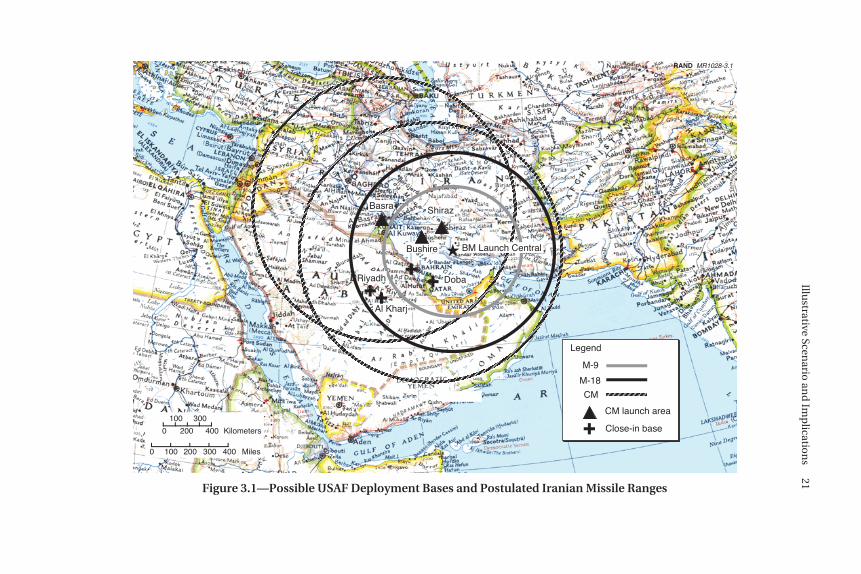
Figure 3.1 shows the locations of postulated USAF deployment basesand the locations and ranges of Iranian missile launches. We chosethe following four USAF deployment bases: Dhahran, Riyadh Mili-tary, Al Kharj (all in Saudi Arabia), and Doha in Qatar.1 Whether
______________1It is possible that the USAF could deploy into more, or different, bases. However, wechose these four bases for several reasons. Dhahran’s enormous parking ramps (seeTable 3.1) make it by far the best location for a massive airlift operation into thetheater. Al Kharj is where most current USAF activity takes place in Saudi Arabia.Riyadh Military is obviously a Saudi military field and is close to the area of anticipatedcombat (Basra), but is far enough from Iran to give the impression of greater safety.Doha was used by USAF F-16s during the 1991 Gulf War and has already hosted an AirExpeditionary Force (AEF) deployment.
������
����
������
������������
���������������������������������
����
���������
��������
��
���
������
��������������
�����������������������
������
����
���
�★
RAND MR1028-3.1
BM Launch Central
���
Legend
M-9
M-18
CM
CM launch area
Basra
Bushire
Shiraz
DobaRiyadh
Al Kharj
0 100 200 300 400
0
100
200
300
400
Miles
Kilometers Close-in base
Figure 3.1—Possible USAF Deployment Bases and Postulated Iranian Missile Ranges
Illustrative Scen
ario an
d Im
plicatio
ns
21
22 Airbase Vulnerability
USAF units deploy into these bases or others is not important as longas the bases are within about 600 nmi of an Iranian missile-launchpoint. Although the choice of specific bases is not critical, these baseswere used in the past as USAF deployment bases. The critical issue isthat short-range aircraft are typically deployed close to the fight inorder to reduce their requirement for the limited tanker sortiesavailable. The figure also shows that, with the exception of a fewbases in the southwestern corner of the country, most bases in SaudiArabia, as well as all bases in Bahrain, Qatar, Oman, and the UnitedArab Emirates (UAE), would be within range of the assumed threat.The Iranians deploy their small, slow cruise missiles on light, truck-mounted launchers, which operate from urban areas, hiding in theclutter. They take advantage of underground parking structures,warehouses, etc., to store and reload their missiles. The cruise-missileunits operate from the Shiraz/Bushire area in Iran and from therecently captured Iraqi city of Basra; mobile ballistic-missile operatingareas are in the mountains south of Shiraz. All missile-launch areasare protected by mutually supporting SA-10 and SA-12 surface-to-airmissile (SAM) launchers.
MISSILE ATTACKS AGAINST USAF ASSETS
With the above scenario providing an operational context, we can nowask, “How effective could missile attacks on USAF airbases be undersuch circumstances?” We decided to quantify the assessment bydetermining how many—or how few—missiles it would take toachieve a 90-percent probability of kill (Pk) on aircraft parked in theopen at the four postulated USAF operating locations.
Basically, we assumed circular submunition dispersal patterns thatwould efficiently destroy parked aircraft. We then calculated the totalexpected lethal area of each submunition warhead by assuming asubmunition-dispersal pattern in which half an aircraft dimension laybetween the lethal area of each of the submunitions in the pattern.This calculation produces a large lethal area for the warhead whileproviding a high probability of kill on an aircraft-sized target within
Illustrative Scenario and Implications 23
the warhead area.2 The simple approach we used for the calculationsis detailed in Appendix A.
The remainder of this section discusses the results of our projectedattacks against the four deployment bases.
Attacking Aircraft
Table 3.1 lists the dimensions of the aircraft parking ramps at the fourUSAF deployment bases. Note the two exceptionally large parkingramps at Dhahran. These two enormous strips of concrete are exactlythe sort of facility required for rapid and efficient aerial port ofdebarkation (APOD) operations, making Dhahran the mostlikely candidate for the theater strategic airlift hub in this conflict, justas it was during Desert Shield/Storm.
The total area of the parking ramps in the table is over 44 millionsquare feet, the equivalent of almost 1,000 football fields. It can ac-commodate a huge number of combat aircraft and an intense aerial-port operation. However, the number of GPS-guided, submunitionwarhead cruise and ballistic missiles required to attack this huge area
Table 3.1
Parking-Ramp Dimensions at Possible USAF Deployment(all dimensions in feet)
Dhahran(likely APOD) Doha Riyadh Al Kharj
9,000 × 900 2,100 × 700 8,400 × 700 6,400 × 1,6004,200 × 600 1,800 × 900 5,600 × 800 5,000 × 1,000
900 × 900 600 × 600 3,300 × 3001,200 × 900 600 × 3002,100 × 700
NOTE: Parking-ramp dimensions are from the National Imagery andMapping Agency, DOD Flight Information Publication: High and LowAltitude Europe, North Africa, and Middle East, St. Louis, Missouri, February27, 1997.
______________2Throughout this document, we assume that a hit results in a functional kill, sinceaircraft are fairly vulnerable to this type of attack and any damage will likely render theaircraft inoperable, at least for the short term. In many cases, the aircraft will beseverely damaged from the attack and subsequent secondary explosions.
24 Airbase Vulnerability
is surprisingly small. Table 3.2 shows just how few missiles are re-quired for a least-cost attack on the parking ramps described in Table3.1.
The table lists the number and type of missiles required to attack theparking ramps at the four bases and the tent cities mentioned in thenext subsection. We varied the effectiveness of the individualbomblets by repeating the analysis for bomblets with five differentassumed lethal radii between 15 and 25 feet. We also assumed thateach base is defended by a Patriot or THAAD battery, and that the
Table 3.2
Least-Cost 0.9-Pk Missile Requirements
Assumed Lethal Radius of 1-Pound Submunition
Weapons Required to Cover: 15 ft 17.5 ft 20 ft 22.5 ft 25 ft
Parking Ramps
No. of M-9 Submunitions 46 41 30 29 26No. of M-18 Submunitions 47 36 30 27 23No. of CM-1s 36 31 38 23 22Cost ($M) $ 151 $ 122 $ 101 $ 90 $ 79
Tent Citiesa
No. of M-9 Submunitions 30 24 20 16 14No. of M-18 Submunitions 30 24 20 16 14Cost ($M) $ 90 $ 72 $ 60 $ 48 $ 42
Patriot/THAAD
No. of CM-1s 12 8 8 8 8Cost ($M) $ 3.6 $ 2.4 $ 2.4 $ 2.4 $ 2.4TOTAL COST ($M) $ 244.6 $ 196.4 $ 163.4 $ 140.4 $ 123.4aThe weapons used to attack tent cities were the same as those used against the aircrafton the ramp. For the tent city, the level of damage would probably not be as high asthat for aircraft, since the submunition dispersion was chosen for attack against largeraircraft targets.
Illustrative Scenario and Implications 25
fire-control radars for these systems are attacked by cruise missiles.3We believe that the dollar values shown are representative of ourassumption that the cruise missiles would cost between $200,000 and$300,000 to mass-produce, and that the ballistic missiles would costapproximately $1 to $2 million each.4,5
Attacking Tent Cities
Tent cities are another possible target set for ballistic and cruisemissiles equipped with submunition warheads. The home-away-from-home for USAF personnel when they deploy to theater operatingbases, the tents serve as sleeping and living quarters, diningfacilities, showers, and, in many cases, they house important adminis-trative and other functions. As Figure 3.2 shows, these areas are large,typically about 1 square kilometer. The tents, vehicles, streets, etc., areall large enough to be easily visible on commercially available satelliteimagery, making detection and targeting fairly simple for countrieshaving the most limited means. Should satellites fail, human-intelligence (HUMINT) sources equipped with GPS could easilyprovide coordinates close enough to the center of tent cities to ensurea missile hit.
However, to attack the entire area of the typical tent city, so many ofthe small cruise missiles we have described would be required that theattack would be costly and difficult to coordinate. Cruise missilescould be used in smaller numbers to harass tent-city residents; but
______________3This refinement of our operational concept—using the low-flying, slow cruise missilesto attack missile-guidance radars—might be a particularly rewarding tactic, since Pa-triot and THAAD have only limited capability to engage such targets and eliminatingthese systems with low, slow cruise missiles could synergistically make ballistic mis-siles much more effective. Here, synergistically refers to the fact that Patriot andTHAAD are being designed against the ballistic missiles. However, ballistic missilescarry a much larger warhead than does the cruise missile postulated. Therefore, themost-effective attack may be to use the cruise missiles to damage the anti–ballistic mis-sile (ABM) systems so that the ballistic missiles will be more effective against the aircrafton the ramps.4See Table A.1 in Appendix A for more-detailed data on assumed missile characteristics.5The authors used their best guess for the cost of ballistic missiles, because data werenot readily available.
26 Airbase Vulnerability
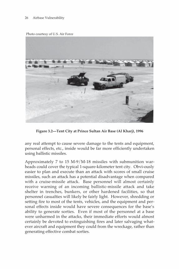
Photo courtesy of U.S. Air Force
Figure 3.2—Tent City at Prince Sultan Air Base (Al Kharj), 1996
any real attempt to cause severe damage to the tents and equipment,personal effects, etc., inside would be far more efficiently undertakenusing ballistic missiles.
Approximately 7 to 15 M-9/M-18 missiles with submunition war-heads could cover the typical 1-square-kilometer tent city. Obvi-ouslyeasier to plan and execute than an attack with scores of small cruisemissiles, such an attack has a potential disadvantage when comparedwith a cruise-missile attack. Base personnel will almost certainlyreceive warning of an incoming ballistic-missile attack and takeshelter in trenches, bunkers, or other hardened facilities, so thatpersonnel casualties will likely be fairly light. However, shredding orsetting fire to most of the tents, vehicles, and the equipment and per-sonal effects inside would have severe consequences for the base’sability to generate sorties. Even if most of the personnel at a basewere unharmed in the attacks, their immediate efforts would almostcertainly be devoted to extinguishing fires and later salvaging what-ever aircraft and equipment they could from the wreckage, rather thangenerating effective combat sorties.
Illustrative Scenario and Implications 27
With most shelter, clothing, and many work centers shredded or de-stroyed, cleanup, clearly, would be the next order of business. Salvageand recovery operations would probably be directed towardevacuating the base and moving the unit’s surviving equipment to alocation beyond the reach of enemy missiles. There, a more completeassessment and recovery could begin, free from the threat of furtherattack.6
However, this process would probably be long, frustrating, and inter-rupted often by further missile attacks. Surviving combat aircraftcould probably leave the base once they had been checked for damageand a foreign-object-free corridor was cleared across the parking rampso that they could taxi to the runway. However, ground trans-portation would have to be enlisted to move surviving groundequipment to the new operating location or to an airport outside of themissile range where airlift operations could proceed without puttingvaluable cargo aircraft at risk.
IN SUM
This chapter has outlined how a hostile power could use faily simple(relative to the Tomahawk), readily available missile and UAVtechnology to launch attacks against USAF operations at theaterairbases. We have shown that, for about $1 billion, an adversarycould attack four missile-defense radars once, four tent cities once,and all parking ramps between 6 and 12 times each. These attackshave the potential to be so destructive to equipment and disruptive tosortie-generation operations that, unless steps are taken to diminishthe effectiveness of these systems, they could force the USAF toabandon bases within reach of enemy missiles. Chapter Four outlinesseveral alternatives available to the USAF to improve the survivabilityof theater airbase operations in the face of a missile threat like the onedescribed above. It also examines some of the potential costs andimpacts on operations of these options. Chapter
______________6For the adversary to replace some of the bomblets with mines could significantlyenhance the effectiveness of an airbase attack. Returning the base to operational statuswould be delayed, since the mines would need to be cleared before the cleanup effortcould get under way.

28 Airbase Vulnerability
Five examines several operational concepts that would enable theUSAF to operate effectively from beyond the effective range of thethreat.
29
Chapter Four
DEFENSIVE RESPONSES TO ANENEMY-MISSILE THREAT
In this chapter, we discuss two different sets of defensive optionsavailable to the USAF to counter submunition-carrying missiles. Thefirst set consists of several passive defenses the USAF could adopt tohelp protect forward-deployed assets; the second set consists of active-defense measures.
Passive defenses are defenses employed by the defender to reduce theimpact of attacks by enhancing its own ability to absorb and recoverfrom attacks. As the name implies, once constructed, passive defensesjust sit there. They have taken many forms throughout humanhistory, from wood-and-mud stockades around a group of huts, to thewalls of medieval cities, to the barbed wire and trenches of World WarI. They are remarkably effective because they are usually simple,reliable, require little or no operator effort to use, and the defender canconstruct obstacles and protective shelters at leisure before a conflictstarts. In contrast, the adversary must wait until the war has started tobreach or dismantle these defenses and must do so under fire.
Active defenses have traditionally required an operator—whether anarcher on a castle wall, a machine gunner in a foxhole, or a surface-to-air missile battery operator—to detect, track, identify, engage, and hitan attacker. They tend to be more complex than passive defenses andrequire considerable operator skill and training. However, they havean advantage: Instead of delaying or deflecting attacks as passivedefenses do, they have the potential to cause substantial damage toenemy equipment and inflict serious casualties.
As is often the case in warfare, active and passive defenses, whencombined, tend to produce far better results than either could alone.
30 Airbase Vulnerability
The archer is much more effective from the top of the castle wall,where he has a commanding field of fire; the machine gunner is lessvulnerable and more effective from the protection of a trench behind abarbed wire entanglement than on flat terrain. Similarly, the passiveand active defense measures described in the following sectionsshould be thought of as mutually reinforcing measures to reduce theeffectiveness of an enemy missile attack rather than as competing,stand-alone solutions to the base-vulnerability problem.
PASSIVE DEFENSES
In the following subsections, we present four possible passive de-fenses for the postulated scenario: fixed hardened shelters, deployableshelters, dispersed aircraft parking, and dispersed operations.
Fixed Hardened Shelters
During the later years of the Cold War, NATO built hundreds of hard-ened concrete shelters to counter possible Soviet aircraft and missileattack, and the Soviets built similar shelters at their opposing bases inEastern Europe. The United States and its allies have constructedsome shelters in South Korea and throughout the Middle East. How-ever, existing facilities in many areas are inadequate to accommodatethe number of combat aircraft the USAF would likely deploy tosuccessfully execute its planned air operations. So, without additionalshelters, USAF combat aircraft would have to be parked in the open asthey were at many bases during the 1991 Gulf War.
Hardened concrete shelters would provide excellent protectionagainst the small submunitions that we postulate future adversariesattempting to shower on USAF theater airbases. In addition, theyprovide a measure of protection against terrorist and special opera-tions force (SOF) attacks, and help protect aircraft from contaminationby gross chemical and biological agents.
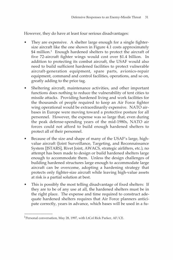
Defensive Responses to an Enemy-Missile Threat 31
However, they do have at least four serious disadvantages:
• They are expensive. A shelter large enough for a single fighter-size aircraft like the one shown in Figure 4.1 costs approximately$4 million.1 Enough hardened shelters to protect the aircraft offive 72-aircraft fighter wings would cost over $1.4 billion. Inaddition to protecting its combat aircraft, the USAF would alsoneed to build sufficient hardened facilities to protect vulnerableaircraft-generation equipment, spare parts, avionics-repairequipment, command and control facilities, operations, and so on,greatly adding to the price tag.
• Sheltering aircraft, maintenance activities, and other importantfunctions does nothing to reduce the vulnerability of tent cities tomissile attacks. Providing hardened living and work facilities forthe thousands of people required to keep an Air Force fighterwing operational would be extraordinarily expensive. NATO air-bases in Europe were moving toward a protective posture for allpersonnel. However, the expense was so large that, even duringthe peak defense-spending years of the mid-1980s, NATO airforces could not afford to build enough hardened shelters toprotect all of their personnel.
• Because of the size and shape of many of the USAF’s large, high-value aircraft (Joint Surveillance, Targeting, and ReconnaissanceSystem [JSTARS], Rivet Joint, AWACS, strategic airlifters, etc.), noattempt has been made to design or build hardened shelters largeenough to accommodate them. Unless the design challenges ofbuilding hardened structures large enough to accommodate largeaircraft can be overcome, adopting a hardening strategy thatprotects only fighter-size aircraft while leaving high-value assetsat risk is a partial solution at best.
• This is possibly the most telling disadvantage of fixed shelters: Ifthey are to be of any use at all, the hardened shelters must be inthe right place. The expense and time required to construct ade-quate hardened shelters requires that Air Force planners antici-pate correctly, years in advance, which bases will be used in a fu-
______________1Personal conversation, May 28, 1997, with LtCol Rick Parker, AF/CE.
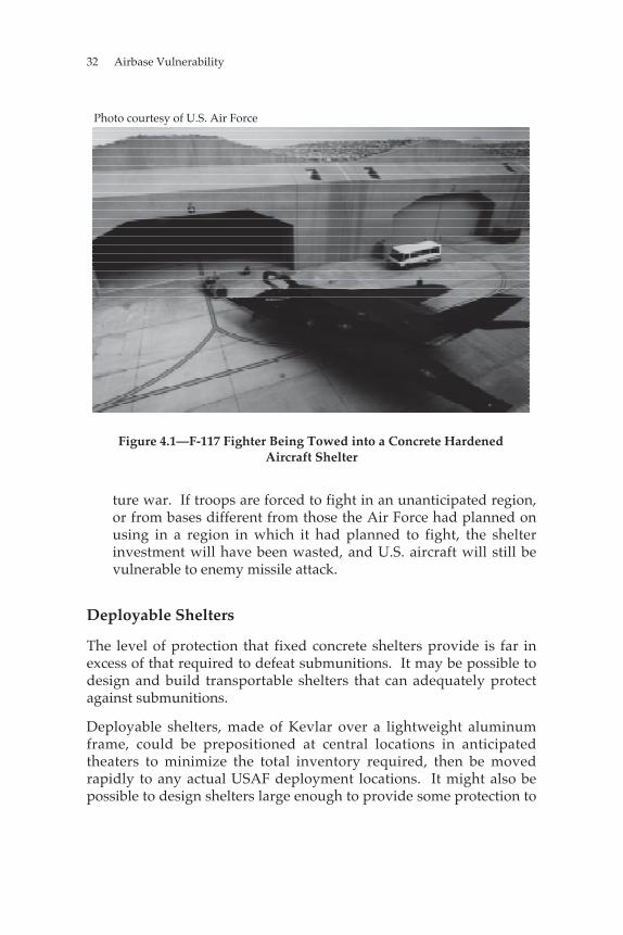
32 Airbase Vulnerability
Photo courtesy of U.S. Air Force
Figure 4.1—F-117 Fighter Being Towed into a Concrete HardenedAircraft Shelter
ture war. If troops are forced to fight in an unanticipated region,or from bases different from those the Air Force had planned onusing in a region in which it had planned to fight, the shelterinvestment will have been wasted, and U.S. aircraft will still bevulnerable to enemy missile attack.
Deployable Shelters
The level of protection that fixed concrete shelters provide is far inexcess of that required to defeat submunitions. It may be possible todesign and build transportable shelters that can adequately protectagainst submunitions.
Deployable shelters, made of Kevlar over a lightweight aluminumframe, could be prepositioned at central locations in anticipatedtheaters to minimize the total inventory required, then be movedrapidly to any actual USAF deployment locations. It might also bepossible to design shelters large enough to provide some protection to
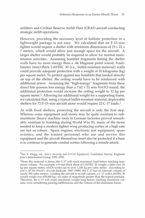
Defensive Responses to an Enemy-Missile Threat 33
airlifters and Civilian Reserve Airlift Fleet (CRAF) aircraft conductingstrategic airlift operations.
However, providing the necessary level of ballistic protection in alightweight package is not easy. We calculated that an F-15–sizefighter would require a shelter with minimum dimensions of 15 × 22 ×7 meters, which would allow just enough space for the aircraft. Alarger shelter would probably be required to allow for normal main-tenance activities. Assuming bomblet fragments hitting the shelterwalls have no more energy than a .44 Magnum pistol round, 9-mil-limeter (mm)-thick LASTEC 30 (i.e., bullet-resistant-material) wallscould provide adequate protection with a weight of 10 kilograms (kg)per square meter. To protect against any bomblets that landed directlyon top of the shelter, the ceiling would have to be reinforced withadditional armor. Assuming the “high-energy” fragments from thesedirect hits possess less energy than a 7.62 × 51 mm NATO round, theadditional protection would increase the ceiling weight to 12 kg persquare meter.2 Allowing for additional weight for a supporting frame,we calculated that, using a typical bullet-resistant material, deployableshelters for 72 F-15–size aircraft alone would require 22 C-17 loads.3
As with fixed shelters, protecting the aircraft is only the first step.Whereas some equipment and stores may be quite resistant to sub-munitions (heavy machine tools in German factories proved remark-ably resistant to bombing during World War II), many of the itemsneeded to keep a modern fighter wing producing sorties at a high rateare not as robust. Spare engines, electronic test equipment, spareavionics, and the trained personnel who use and service thisequipment and the aircraft themselves must also be protected if a baseis to continue to generate combat sorties following a missile attack.
______________2Ian V. Hogg, ed., Jane’s Security and CO-IN Equipment, Coulsdon, Surrey, England:Jane’s Information Group, 1991–1992.3Since this material is dense, the C-17 will reach maximum load before reaching max-imum volume. For example, a 9-mm-thick sheet of LASTEC 30 weighs a little over 10kg per square meter, which works out to over 1,100 kg per cubic meter. According toJane’s All the World’s Aircraft (Jackson, 1997–1998), the C-17 has an internal volume ofnearly 592 cubic meters. Loading the aircraft to its full volume, a C-17 with LASTEC 30would weigh over 650,000 kg—an order of magnitude greater than the typical payload.Therefore, the C-17 will reach maximum weight long before reaching maximum vol-ume, even considering packing inefficiencies and the volume of the aluminum frame.
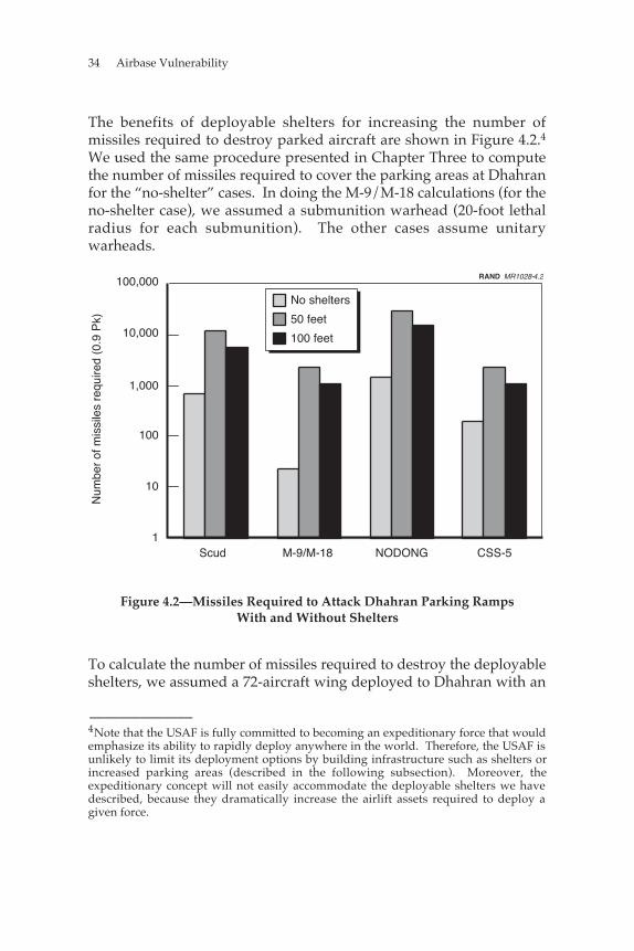
34 Airbase Vulnerability
The benefits of deployable shelters for increasing the number ofmissiles required to destroy parked aircraft are shown in Figure 4.2.4We used the same procedure presented in Chapter Three to computethe number of missiles required to cover the parking areas at Dhahranfor the “no-shelter” cases. In doing the M-9/M-18 calculations (for theno-shelter case), we assumed a submunition warhead (20-foot lethalradius for each submunition). The other cases assume unitarywarheads.
RAND MR1028-4.2
1
10
100
1,000
10,000
100,000
Num
ber
of m
issi
les
requ
ired
(0.9
Pk)
Scud M-9/M-18 NODONG CSS-5
No shelters
50 feet
100 feet
Figure 4.2—Missiles Required to Attack Dhahran Parking RampsWith and Without Shelters
To calculate the number of missiles required to destroy the deployableshelters, we assumed a 72-aircraft wing deployed to Dhahran with an
______________4Note that the USAF is fully committed to becoming an expeditionary force that wouldemphasize its ability to rapidly deploy anywhere in the world. Therefore, the USAF isunlikely to limit its deployment options by building infrastructure such as shelters orincreased parking areas (described in the following subsection). Moreover, theexpeditionary concept will not easily accommodate the deployable shelters we havedescribed, because they dramatically increase the airlift assets required to deploy agiven force.
Defensive Responses to an Enemy-Missile Threat 35
equal number of shelters. The sheltered aircraft are attacked usingmissiles with unitary warheads. In the two cases presented, we variedthe distance within which the unitary warhead must strike the centerof the deployable shelter to register a kill. Inthe first case, the weapon must land within 50 feet of the center of theshelter—essentially landing within about 20 feet of a shelter wall—toregister a kill. In the second case, the weapon must land within 100feet of the center of the shelter—about 70 feet from a shelter wall—tokill the aircraft inside. The numbers presented here assume that theadversary has perfect targeting information for each shelter on theramp (TLE = 0). Note that the scale is logarithmic to facilitate readingthe chart. In all calculations throughout this document, we assume a90-percent probability of kill and the same reliability factor for eachweapon.
Dispersed Aircraft Parking
Another possible way to complicate enemy attempts to attack USAFaircraft parked in the open is to disperse those aircraft over a muchlarger parking area. Figure 4.3 illustrates one way to achieve thatdispersion: taxiways extending outward radially from a base theUSAF anticipates using in a theater conflict. These long taxiwayswould be constructed with many hardstands—far more than thenumber of aircraft operating from the base. The length of the taxi-ways and their radial geometry would maximize the number of mis-siles required to attack the base.
The number of missiles required to attack a given base is a function ofthe distance between contiguous hardstands. Figure 4.4 shows howthe number of missiles required to attack 54 hardstands increases withincreased hardstand spacing. If we assume that an adversary hasaccurate data on where aircraft are parked on the airbase, the numberof weapons required to attack those aircraft successfully increaseswith the distance between hardstands, until that distance is so greatthat each aircraft must be targeted individually. For missiles with thecharacteristics we have described, increasing aircraft spacing beyond750 feet does not increase the number of missiles required to attackt h e m : W h e n u s i n g a c c u r a t e m i s s i l e s , a n
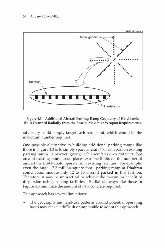
36 Airbase Vulnerability
Radial geometry
Taxiway
Hardstands
RAND MR1028-4.3
Figure 4.3—Additional Aircraft Parking-Ramp Geometry of HardstandsBuilt Outward Radially from the Base to Maximize Weapon Requirements
adversary could simply target each hardstand, which would be themaximum number required.
One possible alternative to building additional parking ramps likethose in Figure 4.3 is to simply space aircraft 750 feet apart on existingparking ramps. However, giving each aircraft its own 750 × 750 footarea of existing ramp space places extreme limits on the number ofaircraft the USAF could operate from existing facilities. For example,even the huge—7.2-million-square-foot—parking ramp at Dhahrancould accommodate only 12 to 15 aircraft parked in this fashion.Therefore, it may be impractical to achieve the maximum benefit ofdispersion using existing facilities. Radial taxiways like those inFigure 4.3 minimize the amount of new concrete required.
This approach has several limitations:
• The geography and land-use patterns around potential operatingbases may make it difficult or impossible to adopt this approach.
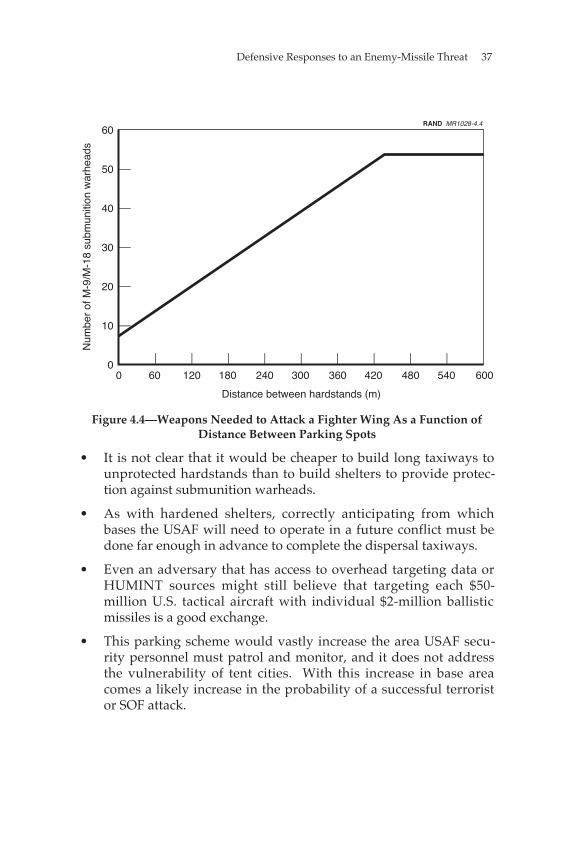
Defensive Responses to an Enemy-Missile Threat 37
0
10
20
30
40
50
60
0 60 120 180 240 300 360 420 480 540 600
Distance between hardstands (m)
Num
ber
of M
-9/M
-18
subm
uniti
on w
arhe
ads
RAND MR1028-4.4
Figure 4.4—Weapons Needed to Attack a Fighter Wing As a Function ofDistance Between Parking Spots
• It is not clear that it would be cheaper to build long taxiways tounprotected hardstands than to build shelters to provide protec-tion against submunition warheads.
• As with hardened shelters, correctly anticipating from whichbases the USAF will need to operate in a future conflict must bedone far enough in advance to complete the dispersal taxiways.
• Even an adversary that has access to overhead targeting data orHUMINT sources might still believe that targeting each $50-million U.S. tactical aircraft with individual $2-million ballisticmissiles is a good exchange.
• This parking scheme would vastly increase the area USAF secu-rity personnel must patrol and monitor, and it does not addressthe vulnerability of tent cities. With this increase in base areacomes a likely increase in the probability of a successful terroristor SOF attack.
38 Airbase Vulnerability
A potentially more-flexible and inexpensive variation on the dispersaloption would be to lay metal-mat parking areas around USAF theateroperating bases after U.S. forces deploy. These temporary rampscould be moved periodically to complicate an adversary’s targetingproblem, and materials could be stockpiled in central locations inlikely theaters to minimize the logistics burden and time forconstruction.
However, these temporary ramps present at least three potential dis-advantages:
• If an adversary knows where the additional temporary ramps are,or can get this information faster than U.S. forces can move theramps, only a few additional missiles would be required to attackthe temporary ramps, unless they are arranged in the radial ge-ometry described above. For example, attacking two 1.5-million-square-foot parking ramps would require only two additionalM-9 or M-18 missiles.
• The temporary parking ramps and taxiways connecting them toexisting base infrastructure would pose a serious foreign-object-damage (FOD) threat to most existing USAF combat aircraft.Unlike Russian combat aircraft, such as the MiG-29, USAF fighterswere designed to operate from well-swept concrete and asphaltsurfaces and have no built-in protective intake covers to preventtheir engines from ingesting dirt, sand, rocks, and other debrislikely to be kicked up as aircraft taxi over the flexible metal matsof the temporary parking areas. F-16s, with their low-mounted jetintakes, would be especially vulnerable to FOD under theseconditions. This particular disadvantage could be addressed byproviding removable intake screens for existing USAF combataircraft. They could be removed or installed in the arming areasbefore and after each flight. Future combat aircraft could bedesigned with anti–FOD-intake protection systems that wouldallow them to operate under more-austere conditions than currentUSAF fighters do. Alternatively, aircraft could be towed to andfrom the metal-mat parking areas.
• The metal-mat-parking-area solution does nothing to decrease thevulnerability of tent cities to missile attack.
Defensive Responses to an Enemy-Missile Threat 39
Dispersed Operations
Another alternative for dealing with the missile threat we have posedis to abandon operations from fixed theater operating bases and dis-perse operations to a large number of small highway strips capable ofhandling 5 to 10 aircraft. An advantage of this option is that itdramatically complicates the attacker’s targeting problem by dispers-ing what was a single large, lucrative target into many much smallerpieces that, individually, are much less vulnerable.
However, dispersed operations would almost certainly complicateand reduce the efficiency of USAF combat operations. Aircraft oper-ations achieve significant efficiency gains from large economies ofscale. For example, aircraft egress systems are so reliable that a wingneeds only 7 to 10 ejection-seat specialists to keep all of its aircraft-egress systems working. However, if the wing is dispersed to 10 or 15separate operating locations, not enough specialists will be availablefor each location to have its own. In addition, many jobs have acomplexity that places special demands on a team of specialists. Theymight take more than one specialist to complete, one individual’swork needs to be inspected and signed off by a second to ensure thatcritical systems are properly repaired, and specialists need to rest.Consequently, the wing probably has only two or three egress teamsavailable to cover the work at 10 to 15 dispersed locations. Similararguments can be made for fuel, hydraulic, propulsion, avionics, andother specialists.
To support dispersed operations, a wing will either need to increaseits maintenance personnel in many specialties or be able to rapidlytransport specialists from one dispersed operating location to another.Delays associated with the need to transport spare parts, especiallycostly or large items such as spare engines, to the dispersed locationsare other possible sources of inefficiency that would decrease sortiegeneration. Requiring aircraft to land with sufficient fuel reserves totake off and immediately refuel from a tanker operating from a basebeyond missile range might solve the fuel-delivery problem at theexpense of some combat radius,5 but delivering the right quantities
______________5If the aircraft needs to land (after a mission) with enough fuel to take off (no groundrefueling) for the next mission, it cannot go as far on the first mission; therefore, in theaggregate, combat radius is reduced.
40 Airbase Vulnerability
and types of munitions to the dispersed locations would probably beas difficult as delivering the right mix of spare parts and maintenancespecialists.
Another problem area would be command-and-control and missionplanning. It might be possible to create an electronic command andcontrol system that would allow dispersed aircrews access to the tar-get, intelligence, and other information they need for planning theirown missions. However, no such system currently exists, and itwould probably be expensive to develop and deploy. Such a systemwould probably also need to have some sort of remote mission-briefing capability, so that crews operating from separate locationscould plan and fly missions together if the USAF wants to retainscheduling flexibility and the capability to put together strike pack-ages exceeding the number of aircraft at a typical dispersed location.
Force protection under this type of operational concept would be anextreme challenge. Relatively small, widely scattered groups of USAFmaintenance personnel and pilots would be exceedingly inviting tar-gets for terrorist or SOF attacks. To protect each operating locationfrom attack by short-range air defense (SHORAD), mortar, or anti-tank guided-missile systems, an area extending out at least5 km from the edges of the dispersed location must be monitored.This area would be almost as large as the security zone surrounding asingle large main operating base, since the dispersed-location runwayswould need to be roughly the same length as the runway at a singleconcentrated base. Dispersing operations to 10 or 15 locations wouldthus increase the area that wing security personnel must monitor andcontrol, by something like 10 to 15 times. Protecting such a large areawould require far more security personnel and resources than USAFwings currently possess.
Finally, an adversary with overhead imagery or HUMINT sources thatcould identify the dispersed operating locations could still target thoselocations with the types of missiles we have described. Effectivenessagainst the missile threat would require that dispersed operatinglocations be capable of rapidly moving between several alternativeoperating sites, which would further reduce sortie-generationcapability.
Defensive Responses to an Enemy-Missile Threat 41
Dispersed operations might prove to be an effective passive defenseagainst enemy missile attacks. And, unlike the other passive-defenseoptions discussed above, dispersed operations decrease the vulner-ability of both aircraft parking areas and tent cities to missile attack.However, to retain current USAF sortie-generation capabilities, thisoperational concept would probably require a huge increase in thenumber of maintenance, security, and support personnel. In addition,it would require the USAF to devise completely new concepts ofcommand and control and logistics, which would probably requireexpensive new computer and communications systems.
Alternative Dispersed-Basing Concept
One possible modification of the dispersed-basing concept that couldaddress some of the concerns raised here is for each wing to maintaina “full-service” base, outside of enemy missile range, with completemaintenance capability; and a forward refueling/re-arming basecloser to the target area and within missile range. Aircraft could begineach day’s activities at the full-service main operating base (MOB), flya mission, and recover at the more-austere and less-capable forward operating base (FOB). To minimize aircraft exposuretime at the FOB, inspections and some servicing might be abbreviatedor deferred. The aircraft and crew could fly one or more sorties fromthe FOB before ending their day by flying back to the MOB, where anydeferred inspections, servicing, and minor maintenance items couldbe attended to, free of the threat of missile attack. A wing using thisbasing system would have higher sortie rates than would a wingoperating solely from a MOB outside missile range, as a result ofreduced transit times to and from the target for any sorties flown fromthe FOB. This system would also expose fewer ground crew to missileattack than would the system for a wing attempting to operate from aMOB inside enemy missile range. However, these advantages come atthe cost of many of the above-described logistics, command-and-control, force-protection, and personnel problems associated withdispersed operations.
Concluding Remarks
This discussion of passive defenses may leave the reader feeling thatthere are no practicable passive-defense options against the sort of
42 Airbase Vulnerability
missile attacks we have postulated. Not so. Aircraft shelters, eitherfixed or deployable, with sufficient ballistic protection against sub-munitions, appear to hold considerable promise. Dispersing aircraftat existing bases or to alternative locations could also work.
However, all of these options come at a substantial cost. Fixed shel-ters are expensive and may not be in the right place. Deployableshelters are heavy, imposing a large, new logistics burden for deploy-ing air wings. Dispersing aircraft at existing bases with permanentnew parking facilities could also work, but may be as costly as build-ing shelters; it shares the disadvantage of being nondeployable.Building temporary parking ramps may be feasible, but would re-quire the USAF to develop equipment and procedures to operate itsexisting and future combat aircraft from much more austere groundfacilities than they are currently capable of using. Finally, dispersedoperating locations could help counter the missile threat, but maycreate new security problems and impose huge new personnel costs.
The USAF may need to adopt a mix of passive-defense options. Forexample, it could work with allied governments to build additionalfixed hardened shelters in theaters where the United States has vitalinterests and anticipates conflict while acquiring enough deployableshelters for two or three wings, to hedge against a conflict in anunanticipated area. The important point is that the USAF should be-gin seriously examining which passive-defense options it might adoptto complement the active-defense options discussed in the nextsection.
ACTIVE DEFENSES
The active defenses discussed in this section are to detect, identify,track, engage, and damage or destroy the two types of offensive sys-tems an adversary could use to attack USAF bases: ballistic missilesand cruise missiles. The ballistic-missile defense problem has beenstudied in great detail by others, and proposals for dealing with itrange from counterforce strikes and patrols to boost-phase interceptusing missiles or directed-energy weapons to anti-missile systemssuch as THAAD and the Navy’s Upper Tier. We do not discuss themerits of these various proposals or their feasibility here. However,we note that it appears that these defenses will cost billions of dollarsto deploy. In this section, we impart some initial thoughts on the
Defensive Responses to an Enemy-Missile Threat 43
types of measures the U.S. military could take to counter the low,slow, small cruise-missile threat we have described.
As discussed in Chapter Two, most existing U.S. air defense systemswere not designed to detect, track, or engage threat systems with thespeed and size of our postulated cruise missiles. Whereas the ballistic-missile threat has multibillion-dollar research programs to developactive defenses to counter it, there are no such programs for cruisemissiles. The lack of such programs is not surprising, for two reasons.First, it is not clear that the threat exists, since no one has yet usedsuch a system in combat.6 Second, the nature of the threat probablydoes not require such a large and expensive research program,because the problems involved in detecting, tracking, and engagingsmall, slow cruise missiles are much more similar to those associatedwith intercepting high-performance aircraft than are the problemsassociated with ballistic-missile defense.
Below, we examine some relatively inexpensive active-defense op-tions available to the USAF for countering low, slow cruise missiles inthe short, medium, and long term.
Short-Term Active Defenses
GPS Jamming. Jamming GPS-guided ballistic and cruise missilescould be an effective counter. At Earth’s surface, the strength of theGPS signal is weak (5 × 10–17 watts).7 A low-power transmitter couldpotentially jam GPS signals over a large area. For example, a 1-wattnoise jammer could jam the signal for a range of 4.5 km against a re-ceiver with no anti-jam countermeasures.8 The overall effectiveness ofGPS jamming depends on a variety of factors and differs markedlywhen such jamming is used against cruise missiles than when used
______________6The same could have been said about aerial torpedoes and 16-inch battleship gunprojectiles modified for use by Japanese naval aircraft against U.S. battleships at PearlHarbor prior to December 7, 1941. For a description of the extensive and uniqueweapon modifications and training program adopted by the Japanese Navy to ensurethe success of the Pearl Harbor attack, see Gordon W. Prangue, At Dawn We Slept,Norwalk, Conn.: The Easton Press, 1988, Chapter 19.7Gerald Frost, Operational Issues for GPS-Aided Precision Guided Weapons, Santa Monica,Calif.: RAND, MR-242-AF, 1994, p. 36.8Frost, 1994, p. 29.
44 Airbase Vulnerability
against ballistic missiles.9 These factors include terrain and systemspecifics, but a few generalizations can be made with regard tojamming effectiveness.10
Two methods are conceivable to jam the GPS guidance system of amissile: noise jamming and “smart” jamming. Given that it could bedifficult to jam the GPS over the launching country, we focus ontarget-area jamming in the following discussion.
Noise jamming is intended to drown the GPS signal reaching themissile in a sea of static-like noise. A missile entering an area in whichthe noise is stronger than the GPS signal would be forced to rely on itsinertial navigation system for guidance. As noted in previous RANDresearch, the accuracy of a gyro can be represented by a drift rate thatis a function of time.11 Since the flight times of cruise missiles aresignificantly greater than those of ballistic missiles, noise jamming willhave a much greater effect on cruise missiles. The effectiveness of thisjamming technique will depend on the countermeasures incorporatedinto the missile.
Although noise jamming offers some hope of decreasing the accuracyand lethality of cruise missiles, this benefit comes at a cost. Thepossible deleterious effects of noise jamming on friendly forces mustalso be considered.
“Smart” jamming seeks to drag the weapon off target by providingbogus GPS input signals. However, this approach is technicallychallenging, since the jammer must know both what satellites arebeing observed by the missile and the intended aimpoint to accuratelyprovide the fraudulent signal. In some cases, knowing the target will
______________9This discussion assumes that the missile systems have a GPS–INS navigation system.Such systems must remain within a jammer’s footprint long enough for the INS to de-velop significant drift errors. An INS with a 0.1-degree-per-hour drift rate deviatesfrom course at about 10 feet per minute. To generate an average miss distance of 1,000feet (enough to miss most, but not all, ramps), the INS must go without updates for 100minutes. If a cruise missile is traveling at 70 knots, it would have to be in the effectivefootprint of a jamming system for at least the final 117 nmi of its flight to miss by 1,000feet on average. For systems equipped with only GPS guidance, limited jammingaround potential targets would be an effective countermeasure, since the missileswould be completely dependent on GPS information.10For an in-depth discussion of the issues associated with GPS jamming, see Frost, 1994.11See Frost and Lachow, 1996a, p. 11.
Defensive Responses to an Enemy-Missile Threat 45
be unnecessary; in others, the fraudulent signal could cause themissile to impact in an undesired location (e.g., in a city).
Lethal Defenses. The slow speed, approximately 70 knots, of thecruise missiles we have described is potentially both their biggest ad-vantage and their biggest disadvantage. It allows them to evade ex-isting U.S. airborne air defense systems by being sorted out as clutteror ground traffic. However, when combined with predictable,computer-controlled flight paths, their slow speed and small sizemake them near-ideal targets for optically aimed medium and heavymachine guns. This weakness could allow the USAF to quicklyemploy simple, existing equipment to good effect against thesesystems. Radar-guided guns could also be highly effective.
One approach would involve deploying small machine-gun teamsconsisting of a gunner and a loader/lookout around bases. Theseteams could wear night-vision goggles to detect, track, and engagesmall, slow cruise missiles. The team’s fields of view and fire could beincreased if they were placed in 20- to 30-meter-tall towers sur-rounding the base, from which well-trained gunners should be able toeffectively engage targets out to at least 300 meters.12 Figure 4.5shows how less than a dozen tower-top teams could provide an inter-locking defense for a 1-square-km tent city and two parking ramps.The gunners would probably not be able to destroy all incomingmissiles; therefore, some form of shelter for aircraft and personnelwould still be necessary.
A gun team detecting a 70-knot cruise missile 500 meters from theedge of the tent city could provide base personnel with only about 15seconds’ warning. Another ring of approximately 30 towers 1 km be-yond the first set of towers could provide an additional layer of de-fense to cause further attrition of attacking cruise missiles, and couldincrease warning time to between 45 seconds and 1 minute.
______________12The cruise missiles we are discussing have lengths and wingspans in the 3–4-meterrange. Although the machine guns mentioned, especially 0.50-caliber weapons, can beeffective at much more than 300 meters, it would probably be difficult for teams toacquire such small targets beyond about 500 meters. Allowing 5 to 7 seconds for theteam to communicate and bring its weapon to bear, we calculate that a target moving at70 knots (36 meters per second) would come within about 275 to 325 meters of the team.
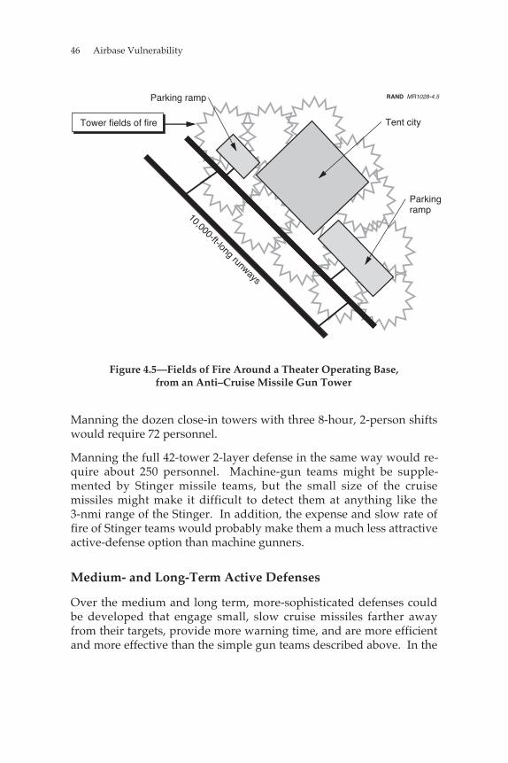
46 Airbase Vulnerability
Tower fields of fire Tent city
10,000-ft-long runways
Parkingramp
RAND MR1028-4.5Parking ramp
Figure 4.5—Fields of Fire Around a Theater Operating Base,from an Anti–Cruise Missile Gun Tower
Manning the dozen close-in towers with three 8-hour, 2-person shiftswould require 72 personnel.
Manning the full 42-tower 2-layer defense in the same way would re-quire about 250 personnel. Machine-gun teams might be supple-mented by Stinger missile teams, but the small size of the cruisemissiles might make it difficult to detect them at anything like the3-nmi range of the Stinger. In addition, the expense and slow rate offire of Stinger teams would probably make them a much less attractiveactive-defense option than machine gunners.
Medium- and Long-Term Active Defenses
Over the medium and long term, more-sophisticated defenses couldbe developed that engage small, slow cruise missiles farther awayfrom their targets, provide more warning time, and are more efficientand more effective than the simple gun teams described above. In the
Defensive Responses to an Enemy-Missile Threat 47
medium term, existing systems such as AWACS, JSTARS, Patriot, orthe Navy’s Phalanx anti-missile gun system might be modified todetect, track, or engage low, slow cruise missiles before they reachtheir intended targets. These modifications might take the form ofnew computer hardware or software to allow systems to track targetsmoving in the 60–90-knot range. Ground-based systems such as Pa-triot would suffer from line-of-sight limitations, even if modified totrack small, slow cruise missiles.
Modifying JSTARS to track such targets seems particularly attractive.From the start, this system was designed to detect and track thou-sands of slow-moving ground targets and fuse these data with knownroads. If JSTARS is sensitive enough to detect small airborne targetslike the cruise missiles we have described, then any targets movingtoward U.S. or allied forces at 60 to 90 knots not on known hard-surface roads would be prime candidates for identification as low,slow cruise missiles. The target information could then be passed onto new gun or missile systems designed to engage cruise missiles.
Over time it might also prove possible to field modified versions ofexisting systems, such as a land-based Phalanx derivative or theAvenger missile/gun system, that would enable low, slow cruisemissiles to be acquired, tracked, and engaged effectively.
All of these proposed long-term adaptations to this postulated threatmight require extensive modification to existing hardware and soft-ware, and would necessitate extensive testing and development ef-forts.
In the long-run, more-effective countermeasures can be developed.These might include air defense systems designed specifically tocounter the slow-cruise-missile threat. These systems might employalternative methods of detecting and tracking their slow-moving tar-gets, such as networks of acoustic sensors, passive millimeter-waveradar, or thermal imaging systems.
This chapter has discussed a number of passive- and active-defenseoptions for countering the threat to USAF theater operating basesposed by cruise and ballistic missiles with submunition warheads.The next chapter explores another option for dealing with the missilethreat: operating from stand-off bases, bases beyond the effectiverange of threat systems.

49
Chapter Five
STAND-OFF OPTIONS
Adopting a stand-off operational concept has benefits for counteringthe emergence of a cruise and/or ballistic missile threat to USAF op-erations from close-in airbases. This chapter explores the benefits andcosts of the stand-off concept. It has two main sections. The firstsection deals with a fairly short-term stand-off operational concept theUSAF could adopt with its current and projected combat-aircraftinventory. The second section examines the potential for a long-termstand-off strategy for operating and employing U.S. land-basedairpower; this strategy would require aircraft with very differentcharacteristics from anything the USAF currently owns or plans toacquire.
SHORT-TERM STAND-OFF OPTIONS
One of the simplest options for dealing with the cruise-missile andballistic-missile threat is to simply avoid it by operating from basesoutside the range of enemy missiles. Figure 5.1 shows the fouralternative deployment bases the USAF could use in our hypotheticalconflict with Iran: King Abdul Aziz, Taif, and Khamis Mushait inSaudi Arabia, and Thumrait in Oman. All of these bases are outsideour proposed cruise-missile range and beyond the reach of ballisticmissiles in the Iranian inventory in this scenario, with the possibleexception of a few dozen CSS-5s, which cannot conduct militarilysignificant conventional warhead attacks against the stand-off basesbecause of their small numbers.
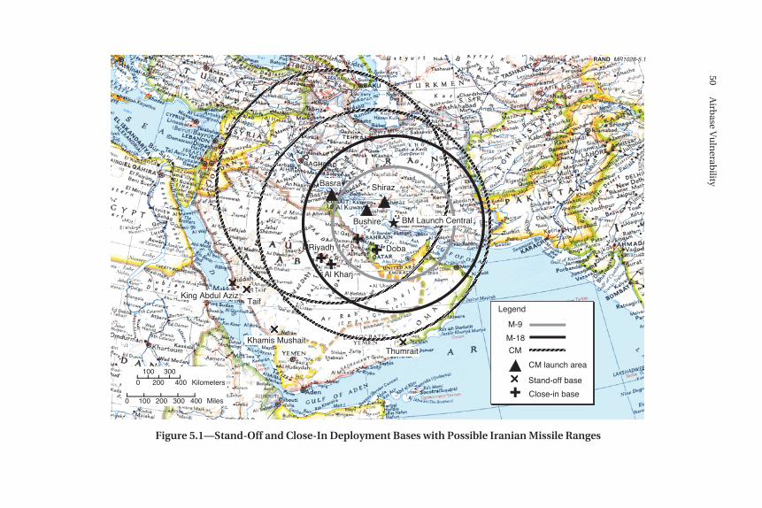
������
����
������
������������
���������������������������������
����
���������
��������
��
���
������
��������������
�����������������������
������
����
���
�★
RAND MR1028-5.1
BM Launch Central
���
Legend
M-9
M-18
CM
Stand-off base
Basra
Bushire
Shiraz
DobaRiyadh
Al Kharj
King Abdul AzizTaif
Khamis MushaitThumrait
0 100 200 300 400
0
100
200
300
400
Miles
Kilometers
Close-in base
CM launch area
Figure 5.1—Stand-Off and Close-In Deployment Bases with Possible Iranian Missile Ranges
50A
irbase V
uln
erability
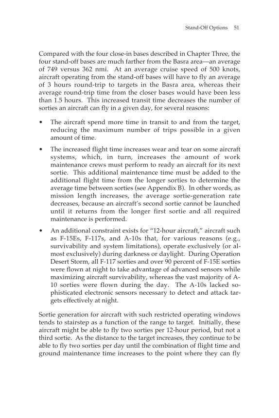
Stand-Off Options 51
Compared with the four close-in bases described in Chapter Three, thefour stand-off bases are much farther from the Basra area—an averageof 749 versus 362 nmi. At an average cruise speed of 500 knots,aircraft operating from the stand-off bases will have to fly an averageof 3 hours round-trip to targets in the Basra area, whereas theiraverage round-trip time from the closer bases would have been lessthan 1.5 hours. This increased transit time decreases the number ofsorties an aircraft can fly in a given day, for several reasons:
• The aircraft spend more time in transit to and from the target,reducing the maximum number of trips possible in a givenamount of time.
• The increased flight time increases wear and tear on some aircraftsystems, which, in turn, increases the amount of workmaintenance crews must perform to ready an aircraft for its nextsortie. This additional maintenance time must be added to theadditional flight time from the longer sorties to determine theaverage time between sorties (see Appendix B). In other words, asmission length increases, the average sortie-generation ratedecreases, because an aircraft’s second sortie cannot be launcheduntil it returns from the longer first sortie and all requiredmaintenance is performed.
• An additional constraint exists for “12-hour aircraft,” aircraft suchas F-15Es, F-117s, and A-10s that, for various reasons (e.g.,survivability and system limitations), operate exclusively (or al-most exclusively) during darkness or daylight. During OperationDesert Storm, all F-117 sorties and over 90 percent of F-15E sortieswere flown at night to take advantage of advanced sensors whilemaximizing aircraft survivability, whereas the vast majority of A-10 sorties were flown during the day. The A-10s lacked so-phisticated electronic sensors necessary to detect and attack tar-gets effectively at night.
Sortie generation for aircraft with such restricted operating windowstends to stairstep as a function of the range to target. Initially, theseaircraft might be able to fly two sorties per 12-hour period, but not athird sortie. As the distance to the target increases, they continue to beable to fly two sorties per day until the combination of flight time andground maintenance time increases to the point where they can fly
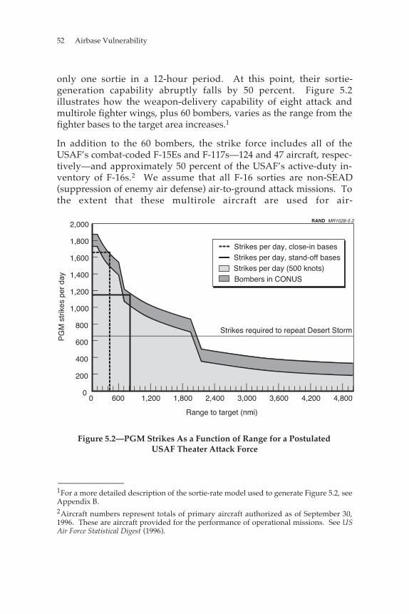
52 Airbase Vulnerability
only one sortie in a 12-hour period. At this point, their sortie-generation capability abruptly falls by 50 percent. Figure 5.2illustrates how the weapon-delivery capability of eight attack andmultirole fighter wings, plus 60 bombers, varies as the range from thefighter bases to the target area increases.1
In addition to the 60 bombers, the strike force includes all of theUSAF’s combat-coded F-15Es and F-117s—124 and 47 aircraft, respec-tively—and approximately 50 percent of the USAF’s active-duty in-ventory of F-16s.2 We assume that all F-16 sorties are non-SEAD(suppression of enemy air defense) air-to-ground attack missions. Tothe extent that these multirole aircraft are used for air-
Strikes per day, close-in basesStrikes per day, stand-off bases
Strikes required to repeat Desert Storm
600 1,200 1,800 2,400 3,000 3,600 4,200 4,800
Strikes per day (500 knots)Bombers in CONUS
Range to target (nmi)
RAND MR1028-5.2
0
2,000
1,800
1,600
1,400
1,200
1,000
800
600
400
200
0
PG
M s
trik
es p
er d
ay
Figure 5.2—PGM Strikes As a Function of Range for a PostulatedUSAF Theater Attack Force
______________1For a more detailed description of the sortie-rate model used to generate Figure 5.2, seeAppendix B.2Aircraft numbers represent totals of primary aircraft authorized as of September 30,1996. These are aircraft provided for the performance of operational missions. See USAir Force Statistical Digest (1996).
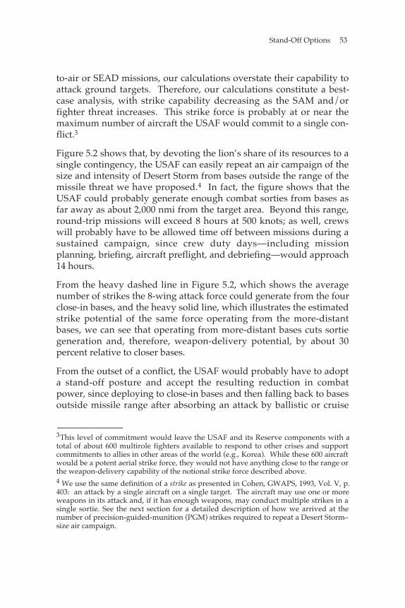
Stand-Off Options 53
to-air or SEAD missions, our calculations overstate their capability toattack ground targets. Therefore, our calculations constitute a best-case analysis, with strike capability decreasing as the SAM and/orfighter threat increases. This strike force is probably at or near themaximum number of aircraft the USAF would commit to a single con-flict.3
Figure 5.2 shows that, by devoting the lion’s share of its resources to asingle contingency, the USAF can easily repeat an air campaign of thesize and intensity of Desert Storm from bases outside the range of themissile threat we have proposed.4 In fact, the figure shows that theUSAF could probably generate enough combat sorties from bases asfar away as about 2,000 nmi from the target area. Beyond this range,round-trip missions will exceed 8 hours at 500 knots; as well, crewswill probably have to be allowed time off between missions during asustained campaign, since crew duty days—including missionplanning, briefing, aircraft preflight, and debriefing—would approach14 hours.
From the heavy dashed line in Figure 5.2, which shows the averagenumber of strikes the 8-wing attack force could generate from the fourclose-in bases, and the heavy solid line, which illustrates the estimatedstrike potential of the same force operating from the more-distantbases, we can see that operating from more-distant bases cuts sortiegeneration and, therefore, weapon-delivery potential, by about 30percent relative to closer bases.
From the outset of a conflict, the USAF would probably have to adopta stand-off posture and accept the resulting reduction in combatpower, since deploying to close-in bases and then falling back to basesoutside missile range after absorbing an attack by ballistic or cruise
______________3This level of commitment would leave the USAF and its Reserve components with atotal of about 600 multirole fighters available to respond to other crises and supportcommitments to allies in other areas of the world (e.g., Korea). While these 600 aircraftwould be a potent aerial strike force, they would not have anything close to the range orthe weapon-delivery capability of the notional strike force described above.4 We use the same definition of a strike as presented in Cohen, GWAPS, 1993, Vol. V, p.403: an attack by a single aircraft on a single target. The aircraft may use one or moreweapons in its attack and, if it has enough weapons, may conduct multiple strikes in asingle sortie. See the next section for a detailed description of how we arrived at thenumber of precision-guided-munition (PGM) strikes required to repeat a Desert Storm–size air campaign.
54 Airbase Vulnerability
missiles would be pointless. Adopting a go-in-close-and-fall-back-if-necessary strategy could result in the loss of a sizable fraction of USAFcombat aircraft and personnel. Additionally, it may be difficult orimpossible to move units out of close-in bases, because the continuingthreat of attack would pose a grave threat to airlift operations, andmost operating surfaces would be strewn with wreckage, posing aserious FOD hazard to surviving combat aircraft.
Figure 5.2 also shows that, over time, it may be possible for adver-saries to force the USAF to operate from bases so far from the scene ofa conflict that even if it commits the bulk of its forces, the USAFcannot sustain an air campaign of the scope and intensity of DesertStorm. This may not mean that the United States will lose a particularconflict, but the Desert Storm effort does at least represent a level ofintensity that quickly defeated a moderately large and sophisticatedadversary. Therefore, that effort represents a not-unreasonableyardstick for measuring the USAF’s potential contribution in a majortheater war (MTW). If enemy missile attacks could seriously degradesortie generation—either by damaging close-in bases or pushing theUSAF to more-distant operating locations—they could seriouslyimpede attainment of important operational goals.
LONG-TERM STAND-OFF OPTIONS
If the USAF knew with a high degree of certainty that it could fight itsnext theater air campaign from permanent bases located on U.S. ter-ritory or the territory of a close ally such as the United Kingdom (UK),many of the problems associated with defenses designed to defeat thesorts of cruise and ballistic missiles we have described would besimplified or eliminated. This is especially true for fixed hardenedshelters for aircraft and personnel: If the USAF knew where it wasgoing to fight from, it could invest in protective facilities without fearthat they would be rendered irrelevant by the need to respond to acrisis at some unexpected location.
Unfortunately, even with air refueling, current USAF combat aircraftprobably could not sustain intense combat operations (which we defineas one sortie per day per aircraft) over a distance of more than about2,000 nmi; such missions simply take too long. A 2,000-nmi missionrequires about 8 hours for an aircraft cruising at 500 knots tocomplete—an extremely long mission for fighter crews. Increasing the
Stand-Off Options 55
cruise speed of USAF attack aircraft would therefore increase the 8-hour mission radius. Figures 5.3 and 5.4 show the areas within reachof a high-spread force5 (cruising at 500 and 1,000 knots, respectively)conducting 8-hour sorties from four “secure” bases: three on U.S.territory—Anderson AFB on Guam; Elmendorf AFB outsideAnchorage, Alaska; and Homestead AFB near Miami, Florida—as wellas secure and virtually permanent access to a facility such as RAFLakenheath outside London, UK.6
Guam
RAND MR1028-5.3
Anchorage
Miami
London
Figure 5.3—Areas That Current 500-Knot Fighter Forces Could Reachfrom Four “Secure” Bases
______________5See Appendix C for a more complete analysis of the high-speed-attack-aircraft concept.6We picked four bases to illustrate the advantages of long-range aircraft. The actualnumber of bases for the force would have to be derived from an analysis of a host ofoperational, logistics, political, and cost factors. Whatever the final number, efficiencyconcerns will keep the number under 10. Although suitable base locations would re-quire further study, the four bases chosen for this analysis are about as far apart fromeach other as possible, giving the most global coverage. An additional base at DiegoGarcia would increase global coverage slightly by bringing the southern tip of Africawithin range, and would provide additional operational flexibility and multiple ingressand recovery options for missions against targets in much of Asia. Expanding basingoptions to all NATO countries might improve the coverage in parts of Africa and Asia.
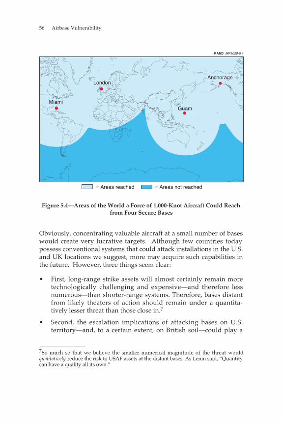
56 Airbase Vulnerability
Miami
LondonAnchorage
Guam
= Areas reached = Areas not reached
RAND MR1028-5.4
Figure 5.4—Areas of the World a Force of 1,000-Knot Aircraft Could Reachfrom Four Secure Bases
Obviously, concentrating valuable aircraft at a small number of baseswould create very lucrative targets. Although few countries todaypossess conventional systems that could attack installations in the U.S.and UK locations we suggest, more may acquire such capabilities inthe future. However, three things seem clear:
• First, long-range strike assets will almost certainly remain moretechnologically challenging and expensive—and therefore lessnumerous—than shorter-range systems. Therefore, bases distantfrom likely theaters of action should remain under a quantita-tively lesser threat than those close in.7
• Second, the escalation implications of attacking bases on U.S.territory—and, to a certain extent, on British soil—could play a
______________7So much so that we believe the smaller numerical magnitude of the threat wouldqualitatively reduce the risk to USAF assets at the distant bases. As Lenin said, “Quantitycan have a quality all its own.”
Stand-Off Options 57
role in deterring opponents from undertaking such strikes in thefirst place.
• Third, by operating forces from a small number of assured, knownfacilities, it may be practical to undertake a number ofpassive and active protection measures, such as hardening andanti-missile defenses, that would be infeasible in today’s world ofdependence on uncertain forward basing.
Another proposal that has been discussed to reduce the USAF’s de-pendence on short-range aircraft is the “arsenal plane,”8 which couldlaunch large numbers of accurate, long-range cruise missiles thatcould effectively operate over very long ranges. But this is only oneway to achieve rapid and robust global conventional attack capability.
We recommend that a concept centered around fast, long-range air-craft be considered. Not only does such a concept address the need toprotect USAF assets from the ever-expanding range of enemy threatsystems, it also promises to greatly ease the kinds of access burdensthat have from time to time troubled U.S. power-projectionoperations.9 Some of the technical issues surrounding such an aircraftare discussed in Appendix C. Furthermore, we recommend that amore detailed study be undertaken to compare this idea with otheroptions (such as 747 “arsenal planes”) for the USAF to determinewhich concept is most technically sound, operationally effective, andfiscally viable.
______________8The Boeing Company, 747 Air-Launched Cruise Missile System Concept, Seattle, Wash.,April 1974.9Saudi Arabia’s reported refusal to support U.S. punitive operations against Iraq inearly 1998 is only the most recent public example of these bedevilments.

59
Chapter Six
CONCLUSIONS
This report has shown how competent and committed adversariescould take advantage of the way in which the USAF plans to conducttheater air operations. They could do so by combining several well-known and widely available technologies, such as UAVs, GPS, sub-munition warheads, and ballistic missiles. Armed with accurate areaweapons capable of inflicting substantial damage on soft-skinnedtargets, such as parked aircraft, tents, radars, and personnel, such anadversary could severely disrupt the USAF’s ability to conduct com-bat operations from theater airbases.
Over the short term, the USAF could respond to this threat by deploy-ing its combat forces with extensive active and passive defenses.However, these measures may be too manpower-intensive, heavy, orexpensive to protect all USAF assets required to support combat op-erations. In addition, some very valuable USAF aircraft, such as air-lifters, bombers, and intelligence, surveillance, and reconnaissance(ISR) platforms, will be very difficult if not impossible to protect pas-sively because of their size. Another alternative is to operate fromdispersed locations or to disperse USAF aircraft more widely at exist-ing facilities. These concepts could work to reduce the effectiveness ofa missile attack against USAF assets but have significant drawbacks oftheir own, such as decreased USAF sortie-generation efficiency,increased logistics costs and complexity, the need to accurately predictthe scene of future conflicts, and failure to address the threat posed totent cities.
Another possible response to long-term increases in adversary missilecapability is to shift away from an operational concept that requires
60 Airbase Vulnerability
large numbers of USAF fighters and their support personnel to deployto a combat theater. Instead, the USAF could rely on a fleet of long-range aircraft operating from permanent bases to project USAFcombat power. Appendix C describes a concept for fast, high-flying,stealthy bombers that could operate in this way.
The options we have discussed here for conducting attacks againstUSAF theater airbases, and the possible USAF defensive responses,are almost certainly incomplete. There are probably other ways toattack the bases, and other options (or combinations of options) fordealing with the attack methods we have presented. However, it isnot important that our descriptions of various attack options repre-sent absolutely accurate predictions of future adversary attack plansor capabilities. What is important is that USAF planners recognizethat the success enjoyed by the USAF during Desert Storm provided apowerful incentive for any nation considering military action thatcould involve conflict with the United States to devise an effectiveplan for dealing with USAF land-based air combat power.
We have shown how such an adversary could go about constructing asimple, robust, effective, and relatively affordable capability to disruptUSAF theater air operations. The options presented here representonly the beginning of a long process of systematically laying out andanalyzing the various options available to the USAF for decreasing itsvulnerability to such attacks.
61
Appendix A
DAMAGE CALCULATION FOR PARKED AIRCRAFT
This appendix describes the method we used to calculate the numberof ballistic and cruise missiles required to destroy aircraft parked onairbase ramps. The method allowed us to look at a significant numberof cases and facilitated a simple and fast spreadsheet analysis of theexpected number of missiles that would be required. We believe theanswers are “ballpark estimates” that show the magnitude of kills thatcan be expected. Further refinement of the method is required. Thisanalysis was conducted using publicly available unclassifiedinformation of likely U.S. deployment bases in Southwest Asia(SWA).1 Technical data on ballistic- and cruise-missile systems alsowas obtained from unclassified sources.2
The calculations require a description of the parking ramps at eachairbase and the accuracy and lethality of the missiles used. In thisappendix, we first describe the input data and simplifying assump-tions used, then describe the calculations for unitary warheads. Next,we discuss the method used to introduce submunition warheads intothe analysis. Finally, we present sample results.
______________1The authors chose the Southwest Asia deployment bases having superior facilities andbased on historical precedent.2Duncan Lennox, ed., Jane’s Strategic Weapon Systems, Coulsdon, Surrey, England:Jane’s Information Group, Issue 24, May 1997.
62 Airbase Vulnerability
DATA AND ASSUMPTIONS
Parking Areas
We obtained data on potential parking areas on an airbase from DODFlight Information Publication: High and Low Altitude Europe, NorthAfrica, and Middle East.3 This information is also available as acomputer database called the Digital Aeronautical Flight InformationFile (DAFIF). These documents are available to the general public atthe unclassified level.
Figure A.1 presents a sample diagram of the airbase at Dhahran.Using such scale drawings, we obtained the dimensions of each of thepotential parking areas on the base. The calculation method we usedassumes that the parking areas are rectangular, which is typical ofmany bases throughout the world.
From the diagram of Dhahran Airbase, we chose the following rect-angular parking areas for attack (all dimensions are in feet):
parking area 1: 9,000 × 900
parking area 2: 4,200 × 600
parking area 3: 900 × 900
parking area 4: 1,200 × 900
parking area 5: 2,100 × 700
Missile Characteristics
The calculations used the lethal radius, l, circular error probable, CEP,and range of potential systems, R. We made simplifications byassuming that the weapons are “cookie cutters”: They have 100-percent effectiveness inside the lethal radius and 0-percent
______________3National Imagery and Mapping Agency, Vol. 5, St. Louis, Missouri, February 27, 1997.
Damage Calculation for Parked Aircraft 63
RAND MR1028-A.1
= Parking area NN
1
2
54
3
SOURCE: National Imagery and Mapping Agency, DoD FlightInformation Publication: High and Low Altitude Europe, North Africa, andMiddle East, Vol. 5, St. Louis, Missouri, February 27, 1997.
Figure A.1—Diagram of Dhahran Airbase
64 Airbase Vulnerability
effectiveness outside, as in the circles in Figure 2.3.4 The difference indownrange and cross-range errors was ignored, and the CEP wasused as the measure of accuracy.
Weaponeering Calculations
Each parking area was assumed to be composed of a series of squares,or blocks, each with the dimension of the minimum length of theparking ramp. For example, the 4,200 × 600 foot parking ramp atDhahran, parking area 2 in Figure A.1, was assumed to be com-posedof seven 600 × 600 foot blocks. For the purpose of obtaining roughestimates and automated calculations, we placed the aimpoint of eachweapon at the center of its respective calculation block (as shown inFigure A.2).
The Reason for the Two-Calculation Regimes
The most important factor in this analysis is the size of the weapon’slethal area relative to that of the target calculation block. Two possi-ble relationships lead to different calculation methods, or regimes: (1)the weapon’s lethal area is smaller than or on the same order as thearea of the calculation block or (2) the weapon’s lethal area is largerthan the area of the calculation block. These assmptions result inballpark estimates, but they allowed us to do quick calculations. Insome places, combinations of l, CEP, etc., can give less-accurateresults. We performed no analyses of the extent of the accuracy.
In the first case, one weapon will not be enough to cover the calcula-tion block, no matter how accurately it can be delivered. In the sec-ond, one accurate weapon may do the job; additional weapons arerequired only when the first does not have the necessary accuracy.We considered the two regimes separately. Later in this appendix,
______________4In the case of a submunition warhead, the “cookie-cutter”-weapon-effect assumptionmeans that at least enough submunitions are distributed throughout the pattern to havea 100-percent probability of kill for the target being considered and no submunitionsfall outside the pattern. This method should provide fairly accurate results that errslightly on the conservative side in kill potential against large-area targets.
Damage Calculation for Parked Aircraft 65
Aimpoints
d
d
RAND MR1028-A2.2
Figure A.2—Layout of Calculation Blocks
we show how analyzing these two regimes separately enabled us tomake assumptions that greatly simplify the calculations so that theylend themselves to fast (and easily automated) calculation methods.
We define the first regime to be a case where the lethal radius of theweapon is less than or equal to half of the minimum dimension of theramp, d. The second is the case where the lethal radius is greater thanhalf of the minimum dimension, d. For both regimes, we assumed a“salvo” attack on the ramp: One weapon was aimed at the center ofeach calculation block for every salvo, and the proportion of the blockcovered by blast and fragments was computed. The number of salvosrequired to achieve a given probability of kill was then calculated.
Regime 1: Weapon’s Effect Small Relative to Block (l ≤ d/2)
Edge Effects. Before we get into a discussion of the calculation, weaddress weapon edge effects. In Figure A.3, the area of the whitesquare and its dark-shaded border represents one of the calculationblocks discussed above (i.e., one of the seven 600 × 600 foot blocks onthe 4,200 × 600 foot ramp at Dhahran). The white block represents thearea in which the impact point of a weapon could lie and withinwhich the weapon effect would be entirely contained. Impact pointswithin the dark-shaded border area (Area 2) and the light-shadedborder area (Area 3) surrounding it result in only partial coverage ofthe calculation block by the weapon.
66 Airbase Vulnerability
Weapon effects Area 2
Area 3
Area 1
Weapon aimpoint
RAND MR1028-A.3
Figure A.3—Diagram for Edge-Effects Analysis
Although a weapon has a slightly higher probability of landing inArea 2 than in Area 3, we neglect this difference in order to simplifythe calculations: We used the entire weapon effect when the impactpoint lies in Area 2, but no weapon effect when the impact is inArea 3.
Diagrams and Terminology. For the following discussion of calcula-tions, we show how parking ramps were divided and grouped.Earlier, Figure A.2 showed a 6d × d aircraft parking ramp divided into6 calculation blocks. The expected area covered by one salvo must becalculated for three block types (interior, transition, and edge). InFigure A.4, the number of blocks, n, is now 10. We allowed the CEPinherent in all weapons to distribute multiple weapons within eachblock. These errors are assumed to be circular and to be normallydistributed about the aimpoint, with the magnitude of the dispersiondetermined by the CEP. The variable “NormDist” in the equations
Damage Calculation for Parked Aircraft 67
Interior blocks
Transition blocks
Edge blocksRAND MR1028-A.4
Figure A.4—Block Terminology
that follow indicates the probability of occurrence using a circularnormal distribution.5
Calculating Area of First Salvo. A salvo is defined as one weaponfired at the center of each block at the same time (as in Figure A.2above).
For each weapon in the first salvo, there are three impact possibilities:6
• The weapon may land in the block at which it was aimed.
• It may land in a different block.
• The weapon may land completely off the ramp.
______________5We chose this method of aimpoint selection, since the CEPs are large (at least on thesame order) relative to the lethal radius for the case being examined in this analysis. Weare simply aiming the weapons on the ramp. This simple aimpoint-choice method failswhen the CEP is small, since we no longer get coverage of the entire ramp. Of course,this is not a problem in the real world: If we were deploying very accurate weapons, wewould simply choose more than one aimpoint in a given calculation square. Thisassumption merely allows us to “automate” the aimpoint selection for these calculations(such “automation” uses the naturally occurring probabilistic spread of the weapons tocover large ramps, so that the aimpoint does not have to be selected for each weapon).6We do not consider the possibility of weapon overlap for weapons in the same salvo.Weapon overlap is considered later, when the number of salvos required to achieve therequired coverage is calculated.
68 Airbase Vulnerability
To simplify the calculations, we first assumed that each block was acircle of equivalent area (we “circled the block”), with the aimpointrepresenting the area’s center, as shown in Block 1 of Figure A.5:
rd d=π
=π
2
(A.1)
Such “circling” should affect the calculation’s validity minimally.
Next, we consider the probability of the weapon’s landing in the blockat which it was aimed (Block 1 in Figure A.5). For our circularizedblocks and a circular weapon with circular normal-distribution impacterrors, this probability is
P rBlock 1 NormDist NormDist= −2 0( ) (A.2)7
The expected area, A, covered in Block 1 by this weapon is
A P lBlock 1 Block 1= π 2 (A.3)
where l is the lethal radius of the weapon.
Next, we consider the possibility of a weapon’s landing in a differentblock from the one at which it was aimed. Again, we assume Block 1to be a circle with radius r as shown in Figure A.5. A circle with ra-dius 3r encompasses both Block 1 and Block 2 (transition block inFigure A.4). An estimate of the probability that the weapon aimed atthe center of Block 1 strikes Block 2 can be obtained by first calculatingthe probability that the weapon will strike in the toroid between acircle with radius r and a circle with radius 3r. Then, since we areassuming a circular distribution, the probability that the weapon willland in Block 2 is simply the ratio of the area of Block 2 to that of thetoroid:
______________7NormDist is the cumulative probability distribution for the value in the subscript.
Damage Calculation for Parked Aircraft 69
3r
Block 2
r
Block 1
RAND MR1028-A.5
Figure A.5—Circular Patterns Superimposed on Calculation Blocks forSame-Block and Different-Block Calculations
PAA Ar r
r rBlock 2
Block 2NormDist NormDist= ( )−−
33
(A.4)
Therefore,
Pr
r rr rBlock 2 NormDist NormDist= ( ) π
π ( ) −⎡⎣⎢
⎤⎦⎥
3
2
2 23– (A.5)
P r rBlock 2 NormDist NormDist= ( )18 3 – (A.6)
The expected area covered in a block by a weapon that was aimed atan adjacent block is simply the probability that it will strike the blockmultiplied by the lethal area of the weapon (remember, we are ne-glecting edge effects). That is,
A P lBlock 2 Block 2= π 2 (A.7)
The final case to be considered here is the expected area covered in ablock by a weapon that was aimed at the center point of a block twoblocks away, presented graphically in Figure A.6 (the edge block inFigure A.4).
70 Airbase Vulnerability
5r circle
3r circle
Block 3 Block 2 Block 1
RAND MR1028-A.6
Figure A.6—Area Covered by Weapon Aimed at Neighboring Blocks
An estimate of the probability that the weapon aimed at the center ofBlock 1 strikes Block 3 can be derived by first determining the proba-bility that the shot lands in the toroid between the circles with radii of3r and 5r, then multiplying that value by the area of Block 3 dividedby the area contained in the toroid. Thus,
PA
A Ar rr r
Block 3Block 3NormDist NormDist= ( )
−5 3
5 3
– (A.8)
Pr
r rr rBlock 3 NormDist NormDist= ( ) π
π −( )5 3
2
2 25 3– (A.9)
P r rBlock 3 NormDist NormDist= ( )116 5 3– (A.10)
The expected area in a block affected by a shot that was aimed at thecenter of a block located two blocks away is again calculated by mul-tiplying the probability by the lethal area of the weapon:
A P lBlock 3 Block 3= π 2 (A.11)
Next, we determine the expected coverage by a salvo of weapons firedat the parking ramp. The number of blocks is
Damage Calculation for Parked Aircraft 71
nxd
= (A.12)
where x is the length of the long axis of the parking ramp and d is thelength of the short axis. Figure A.4 identifies the terminology used inthe discussion below. In this example, n = 10. The expected areacovered by one salvo must be calculated for three block types(interior, transition, and edge) individually. The expected area cov-ered in an interior block is
A A A Ainterior Block 1 Block 2 Block 3= + +2 2 (A.13)
where ABlock 1, ABlock 2, and ABlock 3 refer to the calculations above. Re-call that ABlock 1 is the expected area of the block in question beingcovered by a weapon that was aimed at that block. ABlock 2 is the ex-pected area of the block in question being covered by a weapon thatwas aimed at an adjacent block, and ABlock 3 is the expected area of theblock in question being covered by a weapon that was aimed at ablock on the other side of an adjacent block. The coefficients in theequation above account for the number of each of these types ofblocks. We could extend this calculation to account for weapons thatwere aimed at blocks farther away, but to do so would add needlesscomplexity to our calculations, given that the probabilities quicklydrop off by the very nature of the normal distribution and that theratio of block area to toroid area is reduced with each successive blockaway. Therefore, the probability that a weapon with an aimpointmore than two blocks away affects targets in a calculation block issmall.
The expected area covered in a transition block and in an edge blockfollows by applying this methodology in the context of Figure A.4:
A A A Atransition Block 1 Block 2 Block 3= + +2 (A.14)
A A A Aedge Block 1 Block 2 Block 3= + + (A.15)
Therefore, the total expected area covered by a salvo of N weapons(one aimed at the center point of each of the n blocks) is
72 Airbase Vulnerability
A n A A Atotal interior transition edge= −( ) + +4 2 2 (A.16)
Making the above substitutions and simplifying the equation, we areleft with
A n A A A A Atotal Block 1 Block 2 Block 3 Block 2 Block 3= + +( ) − −2 2 2 4 (A.17)
This calculation accounts for N weapons aimed at the center point ofeach of n blocks, not for the possibility of overlapping weapons;therefore, the area affected is slightly high. However, expecting nooverlap is a fairly good assumption when the lethal radius of theweapon, l, is small relative to the size of the blocks. With this as-sumption, the expected fraction, F, of ramp covered by one salvo is
FA
xd1 salvototal
( ) = (A.18)
Calculation of Salvos Required for Specified Level of Damage.Now we can calculate the number of salvos required to achieve aspecified level of damage on the ramp. For these calculations, we canconsider the possibility of overlap. The total coverage that can beexpected from N salvos is defined as
F FN
N salvos 1 salvo( ) ( )= − −⎡⎣⎢
⎤⎦⎥
1 1 (A.19)
Therefore, the number of salvos, N, required to achieve a specifiedcoverage, Fcoverage req’d, is
NF
F=
−( )−⎡
⎣⎢⎤⎦⎥( )
log
log
1
1
coverage req’d
1 salvo
(A.20)
Regime 2: Weapon’s Effect Large Relative to Block (l > d/2)
Now we turn our attention to the case where the lethal radius is largerthan d/2. This regime is analyzed differently, since one weapon could
Damage Calculation for Parked Aircraft 73
cover more than one block. We again analyze the problem as anumber of blocks with dimensions of the minimum size of the ramp.Again, we assume that one shot is aimed at the center of each of theblocks, and we determine the expected area covered. In this case, oneshot can entirely cover one or more blocks. The most importantsimplifying assumption of this analysis is that a block is considered tobe covered if the center point falls within the “cookie cutter” effect ofthe weapon, shown in Figure A.7. Again, the distribution of weaponimpact points was also assumed to be circular following a normaldistribution, as in Regime 1.
We first consider the possibility that a weapon covers the block atwhich it was aimed. The probability that the center of the block iscovered (and, according to our assumptions, the block itself) is theprobability that the weapon lands within one lethal radius of itsaimpoint (the center of the block). The probability of coverage is
P lBlock 1 NormDist NormDist= −( )2 0 (A.21)
Lethalradius, l
RAND MR1028-A.7
Figure A.7—Calculation Based on Coverage of Center Point of Block
74 Airbase Vulnerability
where l is the lethal radius of the weapon. The expected area coveredis
A P dBlock 1 Block 1= 2 (A.22)
Now, turning our attention to adjacent blocks, we consider the prob-ability that this weapon also covers neighboring blocks. Again, weconsider a block to be 100-percent covered if its center is containedwithin the lethal radius of the shot. In this case, we are looking for theprobability that Block 2 will get covered by a weapon aimed at Block1. Recall that when considering the probability of a weapon’scovering a point, if the weapon lands within the distance l from thatpoint, the point is covered. So, since we want to analyze the proba-bility that a weapon will cover the center point of Block 2, we draw acircle of radius l around that point and recognize that a weapon whoseimpact point is within that circle will cover the center of Block 2.Given that, the question becomes, “What is the probability that aweapon will impact within the circle?” That problem is graphicallypresented in Figure A.8 by the normal distribution superimposed onthe ramp diagram. For the random variable angle ø chosen, we cannow determine the probability of the impact point of the weaponaimed at the center of Block 1 landing within the circle of radius lcentered at Block 2. We do so by computing the area under the curveand between a and b. Now, all values of ø are equally likely, but, ascan be seen in Figure A.8, different values of ø produce differentprobabilities that the weapon will strike the center of Block 2.Therefore, to determine the probability of a shot aimed at Block 1landing within the circle and thus covering Block 2, we mustdetermine the probability of a shot’s landing between a and b for eachangle of ø and then average across all ø.
Figure A.9 presents the method used to determine the values of a andb for each angle of ø. The value of d is known, since it is the distancebetween the aimpoint and the center of the block under consideration,and is the same value d used throughout the preceding 22calculations, since the distance between the center points of two blocksis equal to the dimension of each of the blocks.
In this figure, the two congruent triangles from which a and b aremeasured are along the diagonal line that is inclined at angle ø to the
Damage Calculation for Parked Aircraft 75
l
φ
Block 1Block 2
Aimpoint
RAND MR1028-A.8
b
a
Figure A.8—Diagram for Calculation of Neighboring-Block Coverage
ll
d
a
b
φ
Block 2 Block 1
RAND MR1028-A.9
Figure A.9—Geometry of Neighboring-Block Calculation
76 Airbase Vulnerability
horizontal; therefore, the values of a and b can be derived using thelaw of cosines:
l a d ø2 2 2 2= + − ad cos (A.23)
and
l b d ø2 2 2 2= + − bd cos (A.24)
Noting that the above equations are in quadratic form, we obtain thesolution by applying the quadratic equation:
a b d ø d ø d l, cos cos= ± − +2 2 2 2 (A.25)
The same method can be applied to determine the probability ofcovering a block that is located two or more blocks away from theaimpoints by replacing d with 2d, 3d, . . ., nd in the above equations.Once a and b are determined, the probability of a shot’s landingbetween these two values for a given ø is
P a bBlock 2 NormDist NormDist= − (A.26)
Since we are assuming that all values of ø are equally likely as a resultof the circular error distribution, the probability of a shot aimed at thecenter of Block 1 landing within a circle of radius l centered at Block 2is the average of PBlock 2, calculated above, across all values of ø. PBlock
3 was determined using the same method and replacing d with 2d.
As in Regime 1, the next step is to analyze the effectiveness of a salvoattack. We assume that a salvo of N weapons is fired at the ramp of nblocks with an aimpoint corresponding to the center of each block.For simplicity, the expected coverage of Block 1 is calculated as theexpected coverage by the weapon that was aimed at Block 1 and theexpected coverage from weapons that were aimed at each of the fourmost-proximal blocks. Unlike the analysis of Regime 1, the weaponshave large coverage areas relative to the size of the blocks, and thepossibility of overlap is high, i.e., two weapons aimed at two adjacentblocks could both cover both blocks. Again referring to Figure A.4 forthe block terminology and accepting that we are limiting the calcula-
Damage Calculation for Parked Aircraft 77
tion, for simplicity, to weapons aimed at a particular block and thosethat are aimed at blocks no more than 2d away, we get the followingprobability of coverage for each interior block:
P P P Pinterior Block 1 Block 2 Block 3= − −( ) −( ) −( )1 1 1 12 2
(A.27)
where PBlocks 1, 2, 3 are the probabilities calculated earlier in this dis-cussion of Regime 2 calculations. The second and third terms in thisequation are squared to account for the two blocks on each side of theblock in question.
Likewise, the probability of coverage for the transition and edge blockis
P P P Ptransition Block 1 Block 2 Block= − −( ) −( ) −( )1 1 1 12
3 (A.28)
and
P P P Pedge Block Block Block= − −( ) −( ) −( )1 1 1 11 2 3 (A.29)
Therefore the total expected area covered in the entire parking rampfor one salvo is
A d n P P Ptotal interior transition edge= − + +2 4 2 2[( ) ] (A.30)
where the term d2 is the area of one block. Given that the area of theentire ramp, Aramp, is nd2 , the total expected coverage of the ramp be-comes
FP P P
n1 salvoerior transition edge(n
( ) =− + +4 2 2) int (A.31)
Using the same procedure as that used in Regime 1 to determine thenumber of salvos, N, required to achieve a specified level of coverage,Fcoverage req’d, we obtain
78 Airbase Vulnerability
NF
F=
−( )−⎡
⎣⎢⎤⎦⎥( )
log
log
1
1
coverage req’d
1 salvo
(A.32)
Submunition Warheads
Since large overpressures8 are not required in order to cause signifi-cant damage against soft targets such as aircraft in the open, sub-munition warheads are an ideal weapon. Submunition technologyprovides the capability to significantly damage aircraft over wide ar-eas with relatively small warheads.
The measure of effectiveness of a warhead is the lethal radius withinwhich damage or kill occurs. The lethal radius of a submunitionwarhead depends on the lethal radius of the individual submunitionsand the efficiency of the submunition dispersal, or the ability of theweapon to distribute the individual bomblets uniformly over an area.The best choice for dispersal pattern varies markedly for differenttarget types, e.g., troops in foxholes and aircraft in the open.
This analysis postulates a warhead designed for efficient aircraft at-tack. The warhead is assumed to disperse submunitions uniformly atlarge separation distances, since an aircraft is a large target anddamage to any part can make it unflyable. The warheads are assumedto consist of a number of 1-pound fragmenting bomblets and theadditional mechanics to contain and dispense the submunitions. Weassume bomblets constitute 75 percent of warhead weight and thatmechanical components and structure make up the remaining 25percent.
Sample Results
This section presents some results based on the method describedabove. Table A.1 shows the number of ballistic and cruise missiles ofeach type required to attack each of the ramps at four Southwest Asia
______________8Overpressure is the higher-than-ambient pressure that occurs for a short time in thevicinity of the explosion.
Table A.1
Number of Ballistic and Cruise Missiles of a Given Type Required to Attack Each Ramp at Four Southwest Bases
Scud C M-9 Unit M-9 Sub NODONG M-18 Unit M-18 Sub CSS-5 CM-1 CM-2Reliability 0.7 0.95 0.9 0.7 0.95 0.9 0.95 0.5 0.5CEP (ft) 2,394.4 656 656 6,068 656 656 656 328 328Lethal radius (ft) 241 206 862 260 206 862 260 232 141Fraction of kills
required 0.9 0.9 0.9 0.9 0.9 0.9 0.9 0.9 0.9Cost ($M) 0.2 0.9 1 0.3 1.9 2 3 0.3 0.2
Length (ft) Width (ft)Dhahran Number of Missiles Required
9,000 900 330 170 12 710 170 12 100 110 3004,200 600 154 63 5 336 63 5 42 35 98
900 900 66 23 2 148 23 2 14 11 311,200 900 69 28 2 152 28 2 17 15 412,100 700 87 39 3 192 39 3 24 21 57
Doha2,100 700 87 39 3 192 39 3 24 21 57
600 300 41 14 2 93 14 2 10 6 12600 600 44 15 2 98 15 2 9 6 17
1,800 900 86 38 3 186 38 3 24 22 62Riyadh
5,600 800 210 98 7 455 98 7 63 56 1683,300 300 143 55 5 315 55 5 37 26 448,400 700 300 132 9 660 132 9 84 72 228
Al Kharj6,400 1,600 276 184 7 564 184 7 116 136 3765,000 1,000 200 100 7 420 100 7 60 65 185
Dam
age Calcu
lation
for P
arked A
ircraft79

80 Airbase Vulnerability
bases.9 Every number in the matrix is independent of all others andrepresents the total number of a weapon type to cover a given rampexclusively, with no other weapon types being employed against theramp.
A simple linear program can then be constructed to design an optimalattack strategy within specific constraints. For example, a least-costsolution could be achieved with the constraint that each airbase beattacked by both ballistic and cruise missiles to complicate defenses.
______________9These calculations assume a lethal radius of 20 feet for a 1-pound submunition.
81
Appendix B
SORTIE-RATE MODEL
This appendix describes the method used to calculate aircraft sortierates. Based on earlier unpublished work by former RAND colleagueLawrence Hollett,1 the method was chosen to facilitate a simple andfast spreadsheet analysis of USAF aircraft sortie rates under a varietyof assumptions about range to target, aircraft speed, and basing op-tions. This analysis is based on historical F-15 and F-16 maintenancedata and statistical analysis conducted by the Boeing Corporation onthe relationship between maintenance time, sorties, and sortie dura-tion for Boeing 737 airliners.
The use of airliner data to explore the relationship between mainte-nance requirements, sorties, and sortie duration may seem strange.However, using these data helps us understand and represent the in-fluence on sortie rates of two very distinct classes of aircraft systemfailures: those that are a function of cycling—turning a component onand off—and those that are a function of aggregate time in use.Avionics components, for example, tend to produce cycle-relatedfailures, whereas hydraulic pumps fail in relation to the hours of usethat they have accumulated.
The model presented here relies on a recent study of F-15 and F-16maintenance data2 to help predict the relationship between sortieduration (or distance to target) and maximum sortie rates for USAF
______________1J. Lawrence Hollett, “USAF Responses to Weapons of Mass Destruction Use: StandoffTactical Airpower Projection Option,” unpublished RAND research.2Craig Sherbroke, Using Sorties vs. Flying Hours to Predict Aircraft Spares Demand,McLean, Va.: Logistics Management Institute, April 1997.
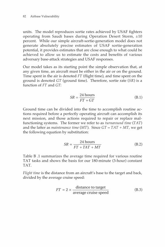
82 Airbase Vulnerability
units. The model reproduces sortie rates achieved by USAF fightersoperating from Saudi bases during Operation Desert Storm, ±10percent. While our simple aircraft-sortie-generation model does notgenerate absolutely precise estimates of USAF sortie-generationpotential, it provides estimates that are close enough to what could beachieved to allow us to estimate the costs and benefits of variousadversary base-attack strategies and USAF responses.
Our model takes as its starting point the simple observation that, atany given time, an aircraft must be either in the air or on the ground.Time spent in the air is denoted FT (flight time), and time spent on theground is denoted GT (ground time). Therefore, sortie rate (SR) is afunction of FT and GT:
SRFT GT
=+
24 hours(B.1)
Ground time can be divided into the time to accomplish routine ac-tions required before a perfectly operating aircraft can accomplish itsnext mission, and those actions required to repair or replace mal-functioning systems. The former we refer to as turnaround time (TAT)and the latter as maintenance time (MT). Since GT = TAT + MT, we getthe following equation by substitution:
SRFT TAT MT
=+ +24 hours
(B.2)
Table B .1 summarizes the average time required for various routineTAT tasks and shows the basis for our 180-minute (3-hour) constantTAT.
Flight time is the distance from an aircraft’s base to the target and back,divided by the average cruise speed:
FT = ×2distance to target
average cruise speed(B.3)
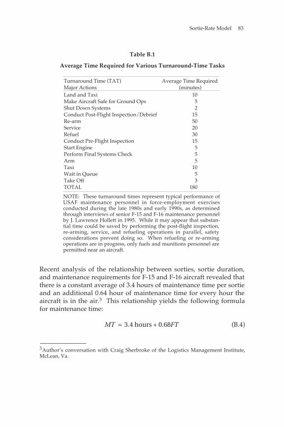
Sortie-Rate Model 83
Table B.1
Average Time Required for Various Turnaround-Time Tasks
Turnaround Time (TAT)Major Actions
Average Time Required(minutes)
Land and Taxi 10Make Aircraft Safe for Ground Ops 5Shut Down Systems 2Conduct Post-Flight Inspection/Debrief 15Re-arm 50Service 20Refuel 30Conduct Pre-Flight Inspection 15Start Engine 5Perform Final Systems Check 5Arm 5Taxi 10Wait in Queue 5Take Off 3TOTAL 180
NOTE: These turnaround times represent typical performance ofUSAF maintenance personnel in force-employment exercisesconducted during the late 1980s and early 1990s, as determinedthrough interviews of senior F-15 and F-16 maintenance personnelby J. Lawrence Hollett in 1995. While it may appear that substan-tial time could be saved by performing the post-flight inspection,re-arming, service, and refueling operations in parallel, safetyconsiderations prevent doing so. When refueling or re-armingoperations are in progress, only fuels and munitions personnel arepermitted near an aircraft.
Recent analysis of the relationship between sorties, sortie duration,and maintenance requirements for F-15 and F-16 aircraft revealed thatthere is a constant average of 3.4 hours of maintenance time per sortieand an additional 0.64 hour of maintenance time for every hour theaircraft is in the air.3 This relationship yields the following formulafor maintenance time:
MT FT= +3.4 hours 0 68. (B.4)
______________3Author’s conversation with Craig Sherbroke of the Logistics Management Institute,McLean, Va.
84 Airbase Vulnerability
So, for a 24-hour aircraft flying a mission against a target 500 nauticalmiles (nmi) from its base with a cruise speed of 500 knots, the sortierate would be
SR FT TAT= + +( )= ( )[ ] +
× ( )[ ]= ( )= ( )=
24 1 68 3 4
24 1 000 3
500
24 2
24 9 76
2 45
hours
hours nmi 500 nmi hour hours
+ 3.4 hours + 0.68 1, 000 nmi nmi hour
hours hours + 3 hours + 3.4 hours + 1.36 hours
hours hours
sorties per day
. .
,
.
.
(B.5)
For 12-hour, “day or night only” aircraft (such as F-117s orA-10s), sortie rates are rounded down to the integer number of sor-tiesan aircraft could fly in a 14-hour period.4 Using the same cruisespeed and distance to target from the above example gives a day-or-night sortie rate of 2, because an aircraft flies a sortie and is ready forrelaunch in 9.76 hours. Its second sortie requires 2 hours, for a total of11.76 hours. There is not enough time to complete the 7.76-houraverage ground cycle before darkness or light makes further opera-tions impractical for the particular aircraft type, so only 2 sorties canbe flown.
Note that, as the distance between an aircraft’s base and its target in-creases, sortie rate decreases, because of two factors. The first andmost obvious is that flight time has increased. However, in thismodel, the increase in flight time also leads to an increase in mainte-nance on those systems sensitive to sortie duration. So, not only domaintenance personnel have less time to work on a given aircraft assortie duration increases (the more time it spends in the air, the less itspends on the ground), but they also have more work to do. As aresult, sortie rate is not a linear function of distance to target.
______________4This assumes an average 12-hour night with 30 minutes each of twilight at dawn anddusk and 30 minutes of transit in darkness or daylight over friendly territory at bothdawn and dusk.
85
Appendix C
FAST, LONG-RANGE-ATTACK AIRCRAFT
In Chapter Five, we recommended a long-term stand-off optioninvolving fast, long-range aircraft. In this appendix, we present anoperational concept for long-range-attack operations to stimulatethought about, and a more thorough investigation of, such optionsavailable to the United States Air Force (USAF) in the early part of thenext century.
WHY FAST ATTACK AIRCRAFT?
All other things being equal, if it is less expensive to develop and de-ploy sophisticated weapons than it is to develop sophisticated deliv-ery platforms, then the USAF should adopt a combination of sophis-ticated, long-range weapons and relatively unsophisticated deliveryplatforms. An example of this approach to the long-range-attackproblem might be thousands of advanced cruise missiles launchedfrom Boeing 747 arsenal planes from outside the range of enemydefenses. However, if developing and deploying sophisticated launchplatforms with less-sophisticated (and less-expensive) weapons is lesscostly than building thousands of advanced cruise missiles, then thebest solution might be something like a Mach 2 penetrating bomberarmed with accurate freefall weapons such as the Joint Direct AttackMunition (JDAM).
86 Airbase Vulnerability to Conventional Cruise and Ballistic Missile Attack
The arsenal plane concept has been explored by others.1 The re-mainder of this appendix explores some of the technical issues sur-rounding the Mach 2 example given above.
OPERATIONAL CONCEPT
In the following analysis, we employ a force of supersonic bomberswith a maximum unrefueled range of 3,250 nautical miles (nmi) toaccomplish an 8,000-nmi combat mission in the following way. First,a force of tanker aircraft escorted by F-22s and the Airborne Warningand Control System (AWACS) departs an operating base. This basewould be equipped with large, submunition-resistant shelters for allaircraft and personnel and be defended by anti–ballistic missile andanti–cruise missile systems.2 Approximately 2 hours after thatdeparture, the bomber force launches from the same base andproceeds to a rendezvous with the refueling force 2,250 nmi from baseat Mach 2, at approximately 60,000 feet.3 At this point the bombersdescend to about 40,000 feet and slow to 500 knots for 30 minutes torefuel. Bombers and tankers are protected by F-22s during thisdelicate operation. Following the refueling, the bombers climb andaccelerate to Mach 2, fly 1,500 nmi to their targets, then egress 1,500nmi to a second refueling rendezvous with a different group oftankers, fighters, and AWACS. The second refueling would occurapproximately 5 hours into the bomber mission (bombers maintain a30-minute fuel reserve in case this second rendezvous is delayed).After refueling, the bombers again accelerate to Mach 2 and proceedback to base. Total bomber mission time is approximately 8 hours.The F-22 mission time is also approximately 8 hours (due to super-
______________1The best exploration has been by The Boeing Company, 747 Air-Launched Cruise MissileSystem Concept, Seattle, Wash., April 1974.2The structures and systems at this base could also be designed to sustain operationsunder chemical and/or biological attack.3For a given speed and size of aircraft, it is possible to calculate an optimal altitude formaximum range. The faster the aircraft, the more drag it produces. Air density anddrag decrease with altitude. Therefore, the faster an aircraft flies, the higher the optimalaltitude will be. Large aircraft capable of sustained Mach 2 speeds, such as the TU144and Concorde, cruise at 60,000 feet, whereas the Mach 3+ SR-71 cruises at 80,000 feet orhigher. Since our proposed aircraft are approximately the same weight as theConcorde, we used a similar flight profile.
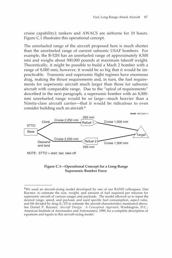
Fast, Long-Range-Attack Aircraft 87
cruise capability); tankers and AWACS are airborne for 10 hours.Figure C.1 illustrates this operational concept.
The unrefueled range of the aircraft proposed here is much shorterthan the unrefueled range of current subsonic USAF bombers. Forexample, the B-52H has an unrefueled range of approximately 8,500nmi and weighs about 500,000 pounds at maximum takeoff weight.Theoretically, it might be possible to build a Mach 2 bomber with arange of 8,000 nmi; however, it would be so big that it would be im-practicable. Transonic and supersonic flight regimes have enormousdrag, making the thrust requirements and, in turn, the fuel require-ments for supersonic aircraft much larger than those for subsonicaircraft with comparable range. Due to the “spiral of requirements”described in the next paragraph, a supersonic bomber with an 8,000-nmi unrefueled range would be so large—much heavier than aNimitz-class aircraft carrier—that it would be ridiculous to evenconsider building such an aircraft.4
STTOClimb Cruise 2,250 nmi
250 nmiCruise 1,500 nmi
Base
Refuel 1
Target
Descendand land
Cruise 2,250 nmiCruise 1,500 nmi
NOTE: STTO = start, taxi, take off.
Refuel 2
250 nmi
RAND MR1028-C.1
Figure C.1—Operational Concept for a Long-RangeSupersonic Bomber Force
______________4We used an aircraft-sizing model developed by one of our RAND colleagues, DanRaymer, to estimate the size, weight, and amount of fuel required per mission forsupersonic aircraft of various ranges and payloads. The model allowed us to input thedesired range, speed, and payload, and used specific fuel consumption, aspect ratio,and lift divided by drag (L/D) to estimate the aircraft characteristics mentioned above.See Daniel P. Raymer, Aircraft Design: A Conceptual Approach, Washington, D.C.:American Institute of Aeronautics and Astronautics, 1989, for a complete description ofequations and inputs to this aircraft-sizing model.
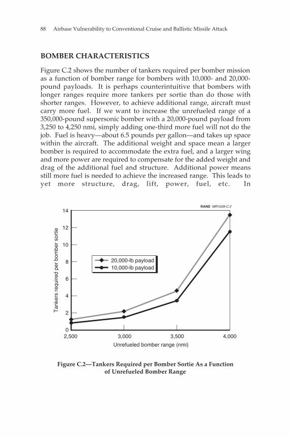
88 Airbase Vulnerability to Conventional Cruise and Ballistic Missile Attack
BOMBER CHARACTERISTICS
Figure C.2 shows the number of tankers required per bomber missionas a function of bomber range for bombers with 10,000- and 20,000-pound payloads. It is perhaps counterintuitive that bombers withlonger ranges require more tankers per sortie than do those withshorter ranges. However, to achieve additional range, aircraft mustcarry more fuel. If we want to increase the unrefueled range of a350,000-pound supersonic bomber with a 20,000-pound payload from3,250 to 4,250 nmi, simply adding one-third more fuel will not do thejob. Fuel is heavy—about 6.5 pounds per gallon—and takes up spacewithin the aircraft. The additional weight and space mean a largerbomber is required to accommodate the extra fuel, and a larger wingand more power are required to compensate for the added weight anddrag of the additional fuel and structure. Additional power meansstill more fuel is needed to achieve the increased range. This leads toyet more structure, drag, lift, power, fuel, etc. In
0
2
4
6
8
10
12
14
2,500 3,000 3,500 4,000
20,000-lb payload10,000-lb payload
Unrefueled bomber range (nmi)
Tan
kers
req
uire
d pe
r bo
mbe
r so
rtie
RAND MR1028-C.2
Figure C.2—Tankers Required per Bomber Sortie As a Functionof Unrefueled Bomber Range
Fast, Long-Range-Attack Aircraft 89
the end, this spiral of requirements leads to an increase in bomberweight from about 350,000 pounds to about 2,200,000 pounds—a 630-percent increase in weight to achieve a 33-percent increase inunrefueled range. The difference in fuel capacity is even greater. The4,250-nmi-range bomber would have a fuel capacity of about 1,350,000pounds, whereas the 3,250-nmi-range bomber would require acapacity of only about 197,000 pounds—a difference of 685 percent.Therefore, although the larger, longer-range bomber could fly a givenmission with 33 percent fewer refuelings, each refueling wouldrequire far more fuel, necessitating more tanker support than theshorter-range bomber.5
Once we have established the desired range of our proposed super-sonic bombers, payload drives bomber size. Obviously, the more eachbomber can carry, the fewer bombers are needed to attack a given setof targets—an argument for very large payloads. However, as withlong range, large payloads lead to large and expensive aircraft. Inaddition, there is a limit to the number of targets a crew can bereasonably expected to plan for and attack on a given mission. Forexample, Air Combat Command currently plans to have its B-1 and B-2 crews attack no more than 8 to 12 targets per mission.
Data from USAF precision-guided-munition (PGM) attacks duringDesert Storm indicate that, when the USAF attacked a target withPGMs, it used, on average, 1.6 weapons, or a total weight of 1,700pounds per target.6 If we assume that the USAF uses the same aver-age number and weight of PGMs to attack targets in future conflicts asit did on average during Desert Storm, an aircraft capable of attacking8 to 12 targets with PGMs would require a payload of between 15,000and 20,000 pounds. Figure C.3 shows the predicted relationshipbetween payload and bomber weight for 3,250-nmi-range
______________5But only up to a certain point. As unrefueled bomber range decreases, the tankersmust refuel the bombers closer to the target and farther from their base. As the tankersfly farther and farther from their base to make off-loads, more tankers are required todeliver a given amount of fuel to the bombers, since the tankers must fly farther both toand from the rendezvous.6Eliot A. Cohen, ed., Gulf War Airpower Survey [GWAPS], Washington, D.C.: U.S. Gov-ernment Printing Office, Vol. V, 1993, pp. 418, 467, 514, 606. These attacks includestrikes using laser-guided bombs, Maverick missiles, and electro-optically guidedbombs.
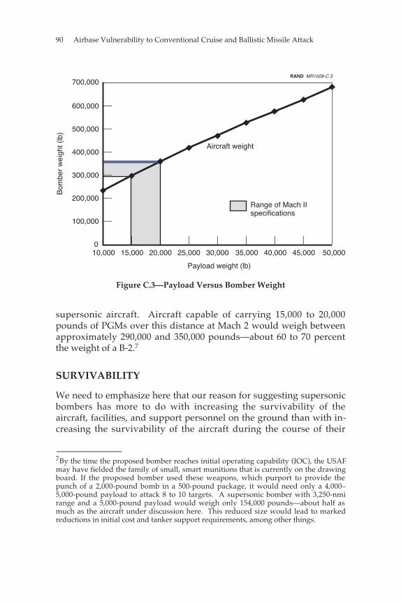
90 Airbase Vulnerability to Conventional Cruise and Ballistic Missile Attack
0
100,000
200,000
300,000
400,000
500,000
600,000
700,000
10,000 20,000 30,000 40,000 50,000
Aircraft weight
Bom
ber
wei
ght (
lb)
Payload weight (lb)
15,000 25,000 35,000 45,000
RAND MR1028-C.3
Range of Mach II specifications
Figure C.3—Payload Versus Bomber Weight
supersonic aircraft. Aircraft capable of carrying 15,000 to 20,000pounds of PGMs over this distance at Mach 2 would weigh betweenapproximately 290,000 and 350,000 pounds—about 60 to 70 percentthe weight of a B-2.7
SURVIVABILITY
We need to emphasize here that our reason for suggesting supersonicbombers has more to do with increasing the survivability of theaircraft, facilities, and support personnel on the ground than with in-creasing the survivability of the aircraft during the course of their
______________7By the time the proposed bomber reaches initial operating capability (IOC), the USAFmay have fielded the family of small, smart munitions that is currently on the drawingboard. If the proposed bomber used these weapons, which purport to provide thepunch of a 2,000-pound bomb in a 500-pound package, it would need only a 4,000–5,000-pound payload to attack 8 to 10 targets. A supersonic bomber with 3,250-nmirange and a 5,000-pound payload would weigh only 154,000 pounds—about half asmuch as the aircraft under discussion here. This reduced size would lead to markedreductions in initial cost and tanker support requirements, among other things.
Fast, Long-Range-Attack Aircraft 91
combat missions. This is a very different motivation from the one thatled the USAF to develop supersonic bombers such as the B-58 and XB-70 in the late 1950s and early 1960s: overcoming increasinglysophisticated and capable Soviet interceptors and surface-to-airmissile (SAM) systems by dramatically increasing the cruise speedsand altitudes of its bomber force. In the era before the advent ofstealth technology, the Soviets showed that they could build radar-guided SAM systems capable of intercepting any high-performancebomber the United States could possibly develop. As a result, the XB-70 was canceled and the B-58 withdrawn from service.
To survive adequately against future surface-to-air and air-to-air de-fenses, our proposed long-range strike aircraft would have to incor-porate features that minimize its radar and infrared signatures. Withthe F-117, B-2, and F-22 behind it, the Air Force and the U.S. aircraftindustry probably possess most of the expertise needed to ensure therequisite degree of radar stealthiness. However, managing theinfrared (IR) signature of an aircraft cruising at Mach 2 will presentsome new challenges.
The heat generated by flight at Mach 2 might make it impossible toproduce a Mach 2 aircraft with a low-IR signature (the Concorde’snose cone reaches 260°F during Mach 2 cruise at 60,000 feet). It mightbe possible to design and build a long-range, high-altitude SAMsystem using an Infra-Red Search and Track System (IRSTS) to detectand track the bombers and IR guidance for the missiles. However, nosuch system currently exists, and the maximum detection range ofsuch a system would be limited by atmospheric absorption of thebomber’s radiated heat. If effective detection range is short, thenumber of SAM sites required to construct an effective barrier wouldbe large. SAMs used as point defenses could be defeated byequipping the bombers with stand-off weapons with ranges thatallowed them to attack targets from outside the range of the defenses.
HOW MANY BOMBERS?
How many supersonic bombers might it take to replicate an offensiveair campaign of the size and intensity of operation Desert Storm?During the course of the 43-day conflict, USAF aircraft conducted
92 Airbase Vulnerability to Conventional Cruise and Ballistic Missile Attack
28,295 strikes—an average of 660 strikes per day. Only about 7,800 ofthese attacks—about 28 percent—were made with PGMs.8 However,to maximize the impact of our bomber force, we propose to attack thesame number of targets using only PGMs. As mentioned in thepreceding section, the USAF used 1,700 pounds of PGMs in each PGMstrike. To attack 660 targets per day with 1,700 pounds of PGMs each,our supersonic bomber force would need to deliver about 560 tons ofPGMs per day. With each aircraft carrying between 7.5 and 10 tons ofPGMs, an effort of this size would require 56 to 75 bomber sorties perday.9 Figure C.4 summarizes this information. Maintaining a readystrike force of 56 to 75 bombers while allowing for training aircraft,test aircraft, aircraft in depot maintenance, etc., would probablyrequire a total force of 80 to 105 aircraft.
SUMMARY
For the supersonic bomber concept described here, a total inventory ofapproximately 80 to 105 Mach 2 bombers with the following char-acteristics could deliver enough PGMs (about 560 tons per day) toreplicate the USAF Desert Storm effort:
• an unrefueled range of 3,250 nmi
• a weight of 290,000 to 350,000 pounds each
• a payload of 15,000 to 20,000 pounds
• support of 37 to 40 percent of the current USAF tanker fleet and100 air superiority fighters.
In addition, Mach 2 bombers could attack targets almost anywhere inthe world while operating from well-protected, permanent bases onU.S. and UK territory.
______________8Cohen, GWAPS, 1993, Vol. V, p. 418. We use the same definition of a strike as pre-sented in Cohen, GWAPS, 1993, Vol. V, p. 403: an attack by a single aircraft on a singletarget. The aircraft may use one or more weapons in its attack and, if it has enoughweapons, may conduct multiple strikes in a single sortie.9On the basis of KC-135R and KC-10 mission profiles computed from their respectiveflight manuals and assuming an 80-percent tanker mission-capable rate, we estimatethat sustaining this level of bomber activity would require the commitment of between37 and 40 percent of the USAF’s total existing tanker capacity. Additional tankerswould be required to support escorting fighters, AWACS, etc.
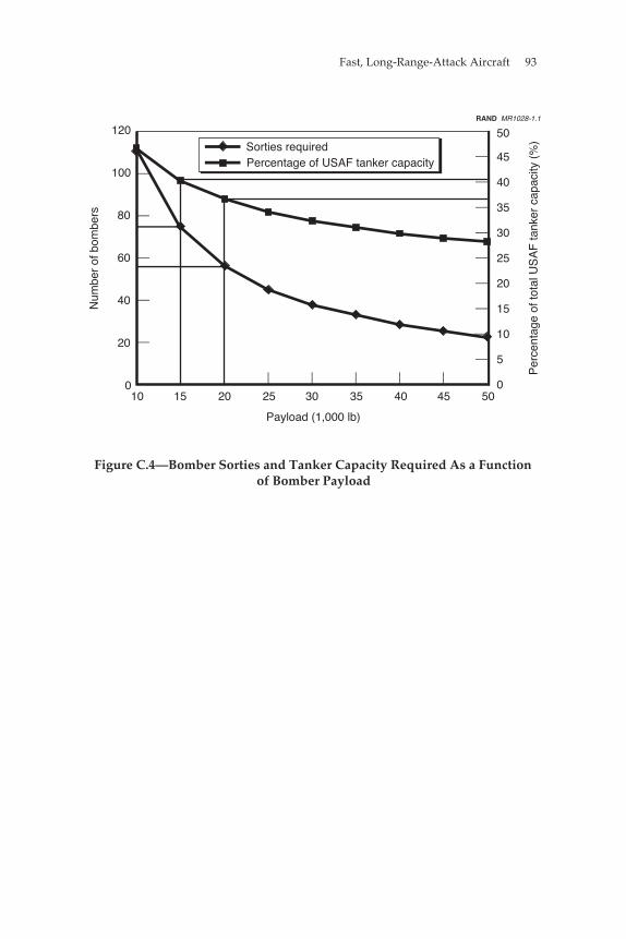
Fast, Long-Range-Attack Aircraft 93
120
100
80
60
40
20
010 15 20 25 30 35 40 45 50
Payload (1,000 lb)
50
45
40
35
30
25
20
15
10
5
0
Percentage of USAF tanker capacitySorties required
Per
cent
age
of to
tal U
SA
F ta
nker
cap
acity
(%
)
Num
ber
of b
ombe
rs
RAND MR1028-1.1
Figure C.4—Bomber Sorties and Tanker Capacity Required As a Functionof Bomber Payload

95
BIBLIOGRAPHY
The Boeing Company, 747 Air-Launched Cruise Missile System Concept,Seattle, Wash., April 1974.
Cohen, Eliot A., ed., Gulf War Air Power Survey, Vol. V: A StatisticalCompendium and Chronology, Washington, D.C.: U.S. GovernmentPrinting Office, 1993.
Chow, Brian, Air Force Operations in a Chemical and Biological Envi-ronment, Santa Monica, Calif.: RAND, DB-189/1-AF, 1998.
Douhet, Giulio, The Command of the Air, Washington, D.C.: Office ofAir Force History, 1983 (originally published in 1921).
Frost, Gerald, Operational Issues for GPS-Aided Precision GuidedWeapons, Santa Monica, Calif.: RAND, MR-242-AF, 1994.
Frost, Gerald, and Irving Lachow, Satellite Navigation-Aiding for Bal-listic and Cruise Missiles, Santa Monica, Calif.: RAND, RP-543,1996a.
———, GPS-Aided Guidance for Ballistic Missile Applications: An As-sessment, Santa Monica, Calif.: RAND, RP 474-1, 1996b.
Hart, Basil Henry Liddell, Thoughts on War, London, 1944.
Hogg, Ian V., ed., Jane’s Security and CO-IN Equipment, Coulsdon,Surrey, England: Jane’s Information Group, 1991–1992.
Jackson, Paul, Jane’s All the World’s Aircraft, Coulsdon, Surrey,England: Jane’s Information Group Limited, 1997–1998.
Joint Chiefs of Staff, Department of Defense Dictionary of MilitaryTerms, Washington, D.C., Joint-Pub 1-02, March 23, 1994.
96 Airbase Vulnerability
Lennox, Duncan, ed., Jane’s Strategic Weapon Systems, Coulsdon,Surrey, England: Jane’s Information Group, Issue 24, May 1997.
Lennox, Duncan S., and Arthur Rees, eds., Jane’s Air LaunchedWeapons, Coulsdon, Surrey, England: Jane’s Information Group,Issue 12, 1990.
Munson, Kenneth, ed., Jane’s Unmanned Aerial Vehicles and Targets,Coulsdon, Surrey, England: Jane’s Information Group, 1995, 1996,1997.
National Imagery and Mapping Agency, DOD Flight InformationPublication: High and Low Altitude Europe, North Africa, and MiddleEast, St. Louis, Missouri, February 27, 1997.
The Nonproliferation Review, Spring–Summer 1995, Vol. 2, No. 3, pp.203–206.
Prangue, Gordon W., At Dawn We Slept, Norwalk, Conn.: The EastonPress, 1988.
Raymer, Daniel P., Aircraft Design: A Conceptual Approach, Wash-ington, D.C.: American Institute of Aeronautics and Astronautics,1989.
Sherbroke, Craig, Using Sorties vs. Flying Hours to Predict Aircraft SparesDemand, McLean, Va.: Logistics Management Institute, April 1997.
Shlapak, David, and Alan Vick, “Check Six begins on the ground”: Re-sponding to the Evolving Ground Threat to U.S. Air Force Bases, SantaMonica, Calif.: RAND, MR-606-AF, 1995.
U.S. Air Force, Facility Requirements, Air Force Handbook AFH 32-1084, September 1, 1996.
US Air Force Statistical Digest, 1996.
Vick, Alan, Snakes in the Eagle’s Nest: A History of Ground Attacks on AirBases, Santa Monica, Calif.: RAND, MR-553-AF, 1995.