control up to four vga video-equipped computer systems and
TRANSCRIPT

Control up to four VGA video-equipped computer systems and share peripherals among them.
KV3004Asupportsonevideoheadperchannel,KV3204Asupportstwo,KV3304Asupportsthree,andKV3404Asupportsfour.
ServSwitch Wizard VGA (USB)
July 2010
KV3004A KV3204A KV3304A KV3404A
Order toll-free in the U.S.: Call 877-877-BBOX (outside U.S. call 724-746-5500)FREE technical support 24 hours a day, 7 days a week: Call 724-746-5500 or fax 724-746-0746Mailing address: Black Box Corporation, 1000 Park Drive, Lawrence, PA 15055-1018Web site: www.blackbox.com • E-mail: [email protected]
Customer Support
Information
®
NETWORK SERVICES
®

ServSwitch Wizard VGA (USB)
724-746-5500 | blackbox.com Page2 724-746-5500 | blackbox.com
Trademarks Used in this ManualBlackBoxandtheDoubleDiamondlogoareregisteredtrademarks,andServSwitchisatrademark,ofBBTechnologies,Inc.
MacisaregisteredtrademarkofAppleComputer,Inc.
LinuxisregisteredtrademarkofLinusTorvalds.
WindowsisaregisteredtrademarkofMicrosoftCorporation.
NetWareisaregisteredtrademarkofNovell,Inc.
SunisatrademarkofSunMicrosystems,Inc.
UnixisaregisteredtrademarkofUNIXSystemLaboratories,Inc.
BSDisaregisteredtrademarkofUUNetTechnologies,Inc.
Anyothertrademarksmentionedinthismanualareacknowledgedtobethepropertyofthetrademarkowners.
We‘reheretohelp!Ifyouhaveanyquestionsaboutyourapplicationorourproducts,contactBlackBoxTechSupportat724-746-5500
orgotoblackbox.comandclickon“TalktoBlackBox.”You’llbelivewithoneofourtechnicalexpertsinlessthan20seconds.

724-746-5500 | blackbox.com
FCC and IC RFI Statements
724-746-5500 | blackbox.com Page3
Federal Communications Commission and Industry Canada Radio Frequency Interference Statements
Thisequipmentgenerates,uses,andcanradiateradio-frequencyenergy,andifnotinstalledandusedproperly,thatis,instrictaccordancewiththemanufacturer’sinstructions,maycauseinterferencetoradiocommunication.IthasbeentestedandfoundtocomplywiththelimitsforaClassAcomputingdeviceinaccordancewiththespecificationsinSubpartBofPart15ofFCCrules,whicharedesignedtoprovidereasonableprotectionagainstsuchinterferencewhentheequipmentisoperatedinacommercialenvironment.Operationofthisequipmentinaresidentialareaislikelytocauseinterference,inwhichcasetheuserathisownexpensewillberequiredtotakewhatevermeasuresmaybenecessarytocorrecttheinterference.
Changesormodificationsnotexpresslyapprovedbythepartyresponsibleforcompliancecouldvoidtheuser’sauthoritytooper-atetheequipment.
ThisdigitalapparatusdoesnotexceedtheClassAlimitsforradionoiseemissionfromdigitalapparatussetoutintheRadioInterferenceRegulationofIndustryCanada.
Leprésentappareilnumériquen’émetpasdebruitsradioélectriquesdépassantleslimitesapplicablesauxappareilsnumériquesdelaclasseAprescritesdansleRèglementsurlebrouillageradioélectriquepubliéparIndustrieCanada.

ServSwitch Wizard VGA (USB)
724-746-5500 | blackbox.com Page4 724-746-5500 | blackbox.com
Instrucciones de Seguridad
(Normas Oficiales Mexicanas Electrical Safety Statement)
1.Todaslasinstruccionesdeseguridadyoperacióndeberánserleídasantesdequeelaparatoeléctricoseaoperado.
2.Lasinstruccionesdeseguridadyoperacióndeberánserguardadasparareferenciafutura.
3.Todaslasadvertenciasenelaparatoeléctricoyensusinstruccionesdeoperacióndebenserrespetadas.
4.Todaslasinstruccionesdeoperaciónyusodebenserseguidas.
5.Elaparatoeléctriconodeberáserusadocercadelagua—porejemplo,cercadelatinadebaño,lavabo,sótanomojadoocercadeunaalberca,etc..
6.Elaparatoeléctricodebeserusadoúnicamenteconcarritosopedestalesqueseanrecomendadosporelfabricante.
7.Elaparatoeléctricodebesermontadoalaparedoaltechosólocomosearecomendadoporelfabricante.
8.Servicio—Elusuarionodebeintentardarservicioalequipoeléctricomásalláalodescritoenlasinstruccionesdeoperación.Todootroserviciodeberáserreferidoapersonaldeserviciocalificado.
9.Elaparatoeléctricodebesersituadodetalmaneraquesuposiciónnointerfierasuuso.Lacolocacióndelaparatoeléctricosobreunacama,sofá,alfombraosuperficiesimilarpuedebloquealaventilación,nosedebecolocarenlibrerosogabinetesqueimpidanelflujodeaireporlosorificiosdeventilación.
10.Elequipoeléctricodebersersituadofueradelalcancedefuentesdecalorcomoradiadores,registrosdecalor,estufasuotrosaparatos(incluyendoamplificadores)queproducencalor.
11.Elaparatoeléctricodeberáserconnectadoaunafuentedepodersólodeltipodescritoenelinstructivodeoperación,ocomoseindiqueenelaparato.
12.Precaucióndebesertomadadetalmaneraquelatierrafisicaylapolarizacióndelequiponoseaeliminada.
13.Loscablesdelafuentedepoderdebenserguiadosdetalmaneraquenoseanpisadosnipellizcadosporobjetoscolocadossobreocontraellos,poniendoparticularatenciónaloscontactosyreceptáculosdondesalendelaparato.
14.Elequipoeléctricodebeserlimpiadoúnicamentedeacuerdoalasrecomendacionesdelfabricante.
15.Encasodeexistir,unaantenaexternadeberáserlocalizadalejosdelaslineasdeenergia.
16.Elcabledecorrientedeberáserdesconectadodelcuandoelequiponoseausadoporunlargoperiododetiempo.
17.Cuidadodebesertomadodetalmaneraqueobjectosliquidosnoseanderramadossobrelacubiertauorificiosdeventilación.
18.Servicioporpersonalcalificadodeberáserprovistocuando:A: Elcabledepoderoelcontactohasidodañado;uB: Objectoshancaídoolíquidohasidoderramadodentrodelaparato;oC: Elaparatohasidoexpuestoalalluvia;oD: Elaparatoparecenooperarnormalmenteomuestrauncambioensudesempeño;oE: Elaparatohasidotiradoosucubiertahasidodañada.

724-746-5500 | blackbox.com
Table of Contents
724-746-5500 | blackbox.com Page5
Contents
1.Specifications.............................................................................................................................................................................. 6
2.Overview.................................................................................................................................................................................... 7
2.1Introduction...................................................................................................................................................................... 7
2.2Features............................................................................................................................................................................ 8
2.3What‘sIncluded................................................................................................................................................................ 8
2.4AdditionalItemsYouMayNeed....................................................................................................................................... 8
2.5HardwareDescription,SingleHeadVersion(KV3004A)................................................................................................... 9
2.6HardwareDescription,MultiHeadVersions(KV3204A,KV3304A,KV3404A)...............................................................11
3.Installation.................................................................................................................................................................................13
3.1Mounting.........................................................................................................................................................................13
3.2Connections................................................................................................................................................................... 14
3.2.1Userconsole....................................................................................................................................................... 14
3.2.2Computersystems............................................................................................................................................. 16
3.2.3Powerinconnection.......................................................................................................................................... 18
3.2.4Channelswitchingbyexternalcontrol............................................................................................................... 19
3.2.5Synchronizingmultipleunits.............................................................................................................................. 21
3.2.6ManagingEDIDvideodisplayinformation.......................................................................................................... 22
4.Configuration........................................................................................................................................................................... 23
4.1UsingtheConfigurationMenu........................................................................................................................................ 23
4.2Generalconfiguration..................................................................................................................................................... 25
4.2.1Changinghotkeys.............................................................................................................................................. 25
4.2.2Mouseswitching................................................................................................................................................ 25
4.2.3OPTIONSportspeed.......................................................................................................................................... 25
4.2.4OPTIONSportchannelcontrolbehavior............................................................................................................ 26
4.2.5Switchingmode................................................................................................................................................. 26
4.2.6Miscellaneousfunctions..................................................................................................................................... 27
4.3Performingupgrades...................................................................................................................................................... 28
5.Operation................................................................................................................................................................................. 30
5.1Selectingacomputer...................................................................................................................................................... 30
5.1.1Selectingacomputerusingthefrontpanel........................................................................................................ 30
5.1.2Selectingacomputerusinghotkeys.................................................................................................................. 31
5.1.3Selectingacomputerusingthemousebuttons.................................................................................................. 32
5.2Lockingaccesstothecomputers.................................................................................................................................... 33
5.3Autoscanning................................................................................................................................................................. 34
AppendixA.WhatisTrueEmulation?.......................................................................................................................................... 36
AppendixB.DefaultEDIDvideomodes........................................................................................................................................ 38
AppendixC.Cablepin-outs......................................................................................................................................................... 39
AppendixD.Safetyinformation................................................................................................................................................... 40

ServSwitch Wizard VGA (USB)
724-746-5500 | blackbox.com Page6 724-746-5500 | blackbox.com
1. Specifications
Approvals: CE,FCC
HardwareCompatibility: AllcomputerswithVGAanalogvideoandUSBinterfaces
SoftwareCompatibility: Operateswithallknownsoftwareandoperatingsystemsincluding Windows®,Linux®,Unix®,BSD,allSun®OS,allMac®OS,NetWare®,etc.
Connectors: Video: 15-wayfemaleD-sub Keyboard/Mouse: USBTypeAfemale SwitchedUSB: USB2.0TypeAfemale Audio: 3.5-mmstereojack Other: Modular10p10cforFlashupgrade,syncwithotherKV3x04Aswitches andRS-232triggeredpowerswitches
OperatingTemperature: 32to104°F(0to40°C)
Power: 2.5mmDCjack(poweradapterincluded) Input: 100–240VAC,50/60Hz Output: 5VDC,2.5Aor4A Consumption: KV3004A: 12.5watts KV3204A,KV3304A,KV3404A: 20watts
Size: KV3004A:1.73"H(1U)x9.21"Wx4.72"D(4.39x23.39x11.99cm) KV3204A,KV3304A,KV3404A:4.375"H(2.5U)x9.21"Wx4.72"D(11.13x23.39x11.99cm)
Weight: KV3004A:1.87lb.(0.85kg); KV3204A:2lb.(0.91kg) KV3304A:2.1lb.(0.95kg); KV3404A:2.2lb.(1kg)

724-746-5500 | blackbox.com
Chapter 2: Overview
724-746-5500 | blackbox.com Page7
2. Overview
2.1 IntroductionTherearefourversionsofthefour-wayServSwitchWizard™VGA(USB),eachofwhichallowsasingleoperatortocontroluptofourcomputersystemsandshareperipheralsamongtheminaveryflexiblemanner.TheKV3004Acansupportonevideoheadperchannel,whereastheslightlylargerKV3204A,KV3304AandKV3404Aunitssupporttwo,threeandfourvideoheadsperchannel,respectively.
InadditiontoimpressiveVGAvideoperformance,theseunitsoffermorethanjuststraightswitchingbetweenfoursystems.TheKVM,speakersandtwoseparateUSBdevicesattachedtotheServSwitchWizardVGA(USB)unitscaneitherbeswitchedinuni-son,asnormal,oryoucanmixyourperipheralsbetweenanyofthesystemstosuityourcurrenttasks.Forinstance,youcouldbecreatingemailsononesystem,listeningtoasoundtrackfromanotherwhileathirdissendingdocumentstoyourprinterandafourthperforminganothertaskwithadifferentUSBperipheral.TheServSwitchWizardVGA(USB)frontpanelsmakeitstraight-forwardtocontrolwhichperipheralsshouldconnecttoeachsystem.
TheServSwitchWizardVGA(USB)unitsfeatureTrueEmulation(seeAppendixAformoredetails)whichensuresthatthefullcharacteristicsoftheconnectedkeyboardandmousearepassedtoeverysystem.
1 2SPKKVM
COMPUTER KVM SPK USB1 USB2 MODE
Multiple switchingTheattachedperipheraldevicescanbeswitchedcollectivelytoanycomputersystem,orcanbelinkedtoseparatesystemstoachievemultipletasksinparallel.Multipleswitchingcanbecontrolledfromtheon-screenmenuorusingthefrontpanelbuttons.
True EmulationEarlierUSBKVMswitchesrelieduponstandardkeyboardandmousetemplatestoinformeachcomputersystemhowtodealwiththeconnectedperipherals.TheServSwitchWizardVGA(USB)rangesucceedsinharvestingthetrueidentitiesoftheconnectedkeyboardandmouseandpresentsthose‘real’profilesconcurrentlytoeverysystem.Thus,specialistkeyboardsandmicecanbefullysupported.
Multiscreen versionsTheServSwitchWizardVGA(USB)rangeincludesseparatemodelstosupportone,two,threeorfourvideoheadsperchannel.
USB Remote wakeupTheUSBRemoteWakeupfeatureisfullysupported.Anyconnectedcomputercangointosleepmodeandbeawakened(whenitschannelisselected)assoonasyoupressakeyormovethemouse.ThecomputerandperipheralsmustsupporttheUSBRemoteWakeupfeature.
Intelligent display informationTheServSwitchWizardVGA(USB)unitsuseourEDIDEmulationfeaturetoensurethatallcomputersaresuppliedwiththecorrectinformationabouteachconnectedvideodisplay.
Figure2-1.OverviewoftheServSwitchWizardVGA(USB).

ServSwitch Wizard VGA (USB)
724-746-5500 | blackbox.com Page8 724-746-5500 | blackbox.com
2.2 FeaturesMultiscreen Versions
TheServSwitchWizardVGA(USB)includesseparatemodelstosupportone,two,three,orfourvideoheadsperchannel.
Multiple Switching
Theattachedperipheraldevicescanbeswitchedcollectivelytoanycomputersystem,ortheycanbelinkedtoseparatesystemstoachievemultipletasksinparallel.Multipleswitchingcanbecontrolledfromtheon-screenmenuorusingthefront-panelbuttons.
Analog Video
TheServSwitchWizardVGA(USB)usesVGAconnectorsthroughoutforfullcompatibilitywithlegacyanalogsystems.
True Emulation
EarlierUSBKVMswitchesrelieduponstandardkeyboardandmousetemplatestotelleachcomputersystemhowtodealwiththeconnectedperipherals.TheServSwitchWizardVGA(USB)rangegathersthetrueidentitiesoftheconnectedkeyboardandmouseandpresentsthose“real”profilesconcurrentlytoeverysystem.Thus,specializedkeyboardsandmicecanbefullysupport-ed.
Intelligent Display Information
TheServSwitchWizardVGA(USB)usesanEDIDemulationfeaturetoensurethatallcomputersaresuppliedwiththecorrectinformationabouteachconnectedvideodisplay.
USB Remote Wakeup
TheServSwitchWizardVGA(USB)fullysupportstheUSBRemoteWakeupfeature.Anyconnectedcomputercangointosleepmodeandbeawakened(whenitschannelisselected)assoonasyoupressakeyormovethemouse.NotethatthecomputerandperipheralsmustalsosupporttheUSBRemoteWakeupfeature.
2.3 What‘s IncludedYourpackageshouldincludethefollowingitems.Ifanythingismissingordamaged,[email protected].
•ServSwitchWizardVGA(USB)unit
• Poweradapterandpowercord
• (4)Self-adhesivefeet
• CD-ROMcontainingthisusermanualinPDFformat
2.4 Additional Items You May Need•VGAvideocable(P/N:EVNPS06)
•USBcable(type-Atotype-B)notexceeding15feet/5m(P/N:USB05)
•Composite2-in-1VGAandUSBcable(P/N:EHN810)
•3.5mmAudiocable(P/N:EJ110)
•Flashupgradeadapter(P/N:FA4509F)*
•(2)19"rackmountbracketsand(4)screws(P/N:RMK2004)*
*TheFA4509FFlashupgradeadaptercomesunassembled;refertoAppendixCforpinning.YouwillalsoneedastandardRJ-45EthernetPatchCordtoconnecttheadaptertotheKVMswitch.Verifythecomputer’sserialconnectorfirstpriortoorderingassomecomputersmaynothaveaDB9connector.
*TherackmountbracketiscompatiblewiththeKV3004Amodelonly

724-746-5500 | blackbox.com
Chapter 2: Overview
724-746-5500 | blackbox.com Page9
2.5 Hardware Description, Single Head Version (KV3004A)
2.5.1 Front PanelFigure2-1showsthefrontpaneloftheunit.Table2-2describesitscomponents:
Figure2-2.Frontpanel.
Table2-1.Frontpanelcomponents.
Number Component Description
1 COMPUTERbutton Presstochangetothenextcomputerchannel.
2 Indicators Thefourindicators(KVM,SPK,USB1,USB2)showwhichperipheralsareswitchedtothecurrentcomputerchannelor(asyoubeginpressingtheMODEbutton)theperipheralsthatwillbeswitchedduringthenextpress(es)oftheCOMPUTERbutton.
Theseven-segmentnumericdisplayindicatesthecomputerchannelthatiscurrentlyactive.
3 MODEbutton Presstodeterminewhichperipheralsshouldbeswitchedtoanothercomputerchannel(willoccurwhenyoupresstheCOMPUTERbutton).
COMPUTER KVM SPK USB1 USB2 MODE
1 2 3

ServSwitch Wizard VGA (USB)
724-746-5500 | blackbox.com Page10 724-746-5500 | blackbox.com
2.5.2 Rear PanelFigure2-3showstherearpaneloftheunit.Table2-2describesitscomponents:
Figure2-3.Rearpanel.
Table2-2.Rearpanelcomponents.
Number Component Description
4 2.5-mmBarrelconnector Powerinputorpowersupplyconnectshere.
5 (2)USBTypeAconnectors Connecttheconsole’sUSBkeyboardandmousetotheseconnectors.
6 3.5-mmRCAconnector Userconsoleaudioport:Connectoptionalspeakerstothisconnector.
7 RJ-45port *Optionsport:Thistop10p10cportisusedtoallowexternalcontrolofchannelswitchingandalsotoupdatetheinternalfirmwarewhennecessarybyconnectingtoacomputer.
8 (4)USBTypeBconnectors ConnecttoaUSBportoneachcomputer.
9 (4)3.5-mmRCAconnectors Connecttothespeakeroutputsocketoneachcomputer(optionalconnection).
10 (2)USBTypeAconnectors Connecttotheconsole'sUSB2.0peripheraldevices(optionalconnection).
11 (4)VGAconnectors Connecttothevideooutputportofeachcomputer.
12 VGAconnector Connecttotheconsole'svideomonitor
*NOTE:TheOPTIONSportusesa10p10csocket,whichcanaccommodateboth10p10cconnectorsaswellasthemuchmorecommon8p8cconnectors,whichareusedonEthernetleadsandpatchcables.Thepin-outsforbothtypesofconnectorsarelistedinAppendixC.
4 3 2 1
USB2.0SWITCHED
USB 1
USB 2
5V
2.5A
INDOORUSE
ONLYUSERCONSOLE
OPTIONS
12 11 11 11 11
4 5 6 7 8 9 8 9 8 9 8 9 10

724-746-5500 | blackbox.com
Chapter 2: Overview
724-746-5500 | blackbox.com Page11
2.6 Hardware Description, Multi Head Versions (KV3204A, KV3304A, KV3404A)
2.6.1 Front PanelFigure2-4showsthefrontpaneloftheunit.Table2-3describesitscomponents:
Figure2-4.Frontpanel.
Table2-3.Frontpanelcomponents.
Number Component Description
1 COMPUTERbutton Presstochangetothenextcomputerchannel.
2 Indicators Thefourupperindicators(KVM,SPK,USB1,USB2)showwhichperipheralsareswitchedtothecurrentcomputerchannelor(asyoubeginpressingtheMODEbutton)theperipheralsthatwillbeswitchedduringthenextpress(es)oftheCOMPUTERbutton.
Thefourlowerindicators,labeledV1toV4,showthevideochannelsbeingswitched.
Theseven-segmentnumericdisplayindicatesthecomputerchannelthatiscurrentlyactive.
3 MODEbutton Presstodeterminewhichperipheralsshouldbeswitchedtoanothercomputerchannel(willoccurwhenyoupresstheCOMPUTERbutton).
COMPUTER KVM
V1
SPK
V2
USB1
V3
USB2
V4
MODE
1 2 3

ServSwitch Wizard VGA (USB)
724-746-5500 | blackbox.com Page12 724-746-5500 | blackbox.com
2.6.2 Rear PanelFigure2-5showstherearpaneloftheunit.Table2-4describesitscomponents:
1234
USB2.0SWITCHED
USB 1
USB 2
V1
V2
V3
V4
5V
4A
INDOORUSE
ONLY
USERCONSOLE
OPTIONS
12 11 11 11 11
4 5 6 7 8 9 8 9 8 9 8 9 10
Figure2-5.Rearpanel.
Table2-4.Rearpanelcomponents.
Number Component Description
4 2.5-mmBarrelconnector Powerinputorpowersupplyconnectshere.
5 (2)USBTypeAconnectors Connecttheconsole’sUSBkeyboardandmousetotheseconnectors.
6 3.5-mmRCAconnector Userconsoleaudioport:Connectoptionalspeakerstothisconnector.
7 RJ-45port *Optionsport:Thistop10p10cportisusedtoallowexternalcontrolofchannelswitchingandalsotoupdatetheinternalfirmwarewhennecessarybyconnectngtoacomputer.
8 (4)USBTypeBconnectors ConnecttoaUSBportoneachcomputer.
9 (4)3.5-mmRCAconnectors Connecttothespeakeroutputsocketoneachcomputer(optionalconnection).
10 (2)USBTypeAconnectors Connecttotheconsole'sUSB2.0peripheraldevices(optionalconnection).
11 (8,12or16)VGAconnectors Connecttothevideooutputportsofeachcomputer.
12 (2,3or4)VGAconnectors Connecttotheconsole'svideomonitorstoenablemultiplevideostreamsfromeachcomputertobeswitchedtouptofourvideomonitors.
*NOTE:TheOPTIONSportusesa10p10csocket,whichcanaccommodateboth10p10cconnectorsaswellasthemuchmorecommon8p8cconnectors,whichareusedonEthernetleadsandpatchcables.Thepin-outsforbothtypesofconnectorsarelistedinAppendixC.

724-746-5500 | blackbox.com
Chapter 3: Installation
724-746-5500 | blackbox.com Page13
3. Installation
3.1 MountingTherearetwomainmountingmethods:
•Viathe(4)suppliedself-adhesiverubberfeet
•Viaoptionalrackmountbrackets(KV3004Amodelonly)usingRMK4007
Rack brackets (KV3004A model only)
Theoptionalbrackets(plusfourscrews),enabletheunittobesecuredwithinastandardrackslot.SeeFigure3-1.
1
USB2.0SWITCHED
USB 1
USB 2
4
3
5V
2.5A
INDOORUSEONLY
USERCONSOLE
OPTIONS
Figure3-1.Rackmountbrackets(KV3004Aonly).
NOTE:BoththeServSwitchWizardVGA(USB)unitanditspowersupplygenerateheatwheninoperationandwillbecomewarmtothetouch.Donotenclosethemorplacetheminlocationswhereaircannotcirculatetocooltheequipment.Donotoperatetheequipmentinambienttemperaturesexceeding104°F(40°C).Donotplacetheproductsincontactwithequipmentwhosesurfacetemperatureexceeds104°F(40°C).

ServSwitch Wizard VGA (USB)
724-746-5500 | blackbox.com Page14 724-746-5500 | blackbox.com
3.2 ConnectionsConnectionsdonotneedtobecarriedoutintheordergivenwithinthisguide,however,wherepossibleconnectthepower inasafinalstep.
3.2.1 User consoleTheportsthatmakeuptheuserconsolearewhereyouattachtheperipheralsthatwillbesharedbetweenthecomputersystems.Ensurethatpowerisdisconnectedfromtheunit.
To connect peripherals to the user console
1 Positionyourperipheraldevicesinthevicinityoftheunitsuchthattheircableswilleasilyreach.
2 Keyboardandmouse:AttachtheleadsfromyourUSBkeyboardandmousetotheUSBsocketsspecificallylabeledwithkey-boardandmousesymbols.ThekeyboardandmousewilloperateinanyoftheUSBsockets,however,TrueEmulationisnotavailableonsocketslabelledUSB1orUSB2.SeeFigure3-2.
2
1
USB2.0SWITCHED
USB 1
USB 2
5V
2.5A
INDOORUSEONLY
USERCONSOLE
OPTIONS
Figure3-2.Connectingthekeyboard/mousetotheuserconsole.
3 USBdevices:Whererequired,attachtheleadsfromyourUSBperipheralstotheUSBsocketslabelledUSB1andUSB2.SeeFigure3-3.
Figure3-3.ConnectingUSBperipheralstotheuserconsole.

724-746-5500 | blackbox.com
Chapter 3: Installation
724-746-5500 | blackbox.com Page15
4 Videomonitor(s):VGAvideoportsareusedthroughout.
Single screen units:AttachtheleadfromthevideomonitortotheVGAconnectoroftheuserconsolearea.SeeFigure3-4.
INDOORUSEONLY
USERCONSOLE
OPTIONS
1
2
3
4
5V
2.5A
INDOORUSEONLY
USERCONSOLE
OPTIONS
5V
2.5A
INDOORUSEONLY
USERCONSOLE
OPTIONS
Figure3-4.Connectingavideomonitortotheuserconsole.
Multiscreen units:AttachtheleadfromeachvideomonitortoaVGAconnectoroftheuserconsolearea.SeeFigure3-5.
Figure3-5.Connectingmultiplevideomonitorstotheuserconsole.
Note: On the rear panel of the unit, the connectors at each horizontal level (V1 to V4) will be switched through to the user console VGA connector which is at the same level.
5 Audio:Whererequired,connecttheleadfromyourspeakerstotheaudiosocket.SeeFigure3-6.
Figure3-6.Connectingspeakerstotheuserconsole.

ServSwitch Wizard VGA (USB)
724-746-5500 | blackbox.com Page16 724-746-5500 | blackbox.com
3.2.2 Computer systemsEachcomputersystemisconnectedtotheServSwitchWizardVGA(USB)unitusinguptothreecablesfortheKV3004AanduptosixcablesfortheKV3204A,KV3304AandKV3404A.
To connect a computer system
1 EnsurethatpowerisdisconnectedfromtheServSwitchWizardVGA(USB)unitandthesystemtobeconnected.
2 UseaUSBcable(type-Atotype-B)tolinkaUSBportonthecomputersystemtotheUSBportoftherequiredchannelontherearoftheunit.SeeFigure3-7.
2
1
USB2.0SWITCHED
USB 1
USB 2
2
1
USB2.0SWITCHED
USB 1
USB 2
Figure3-7.ConnectingtheUSBandspeakerleadsfromacomputertotheServSwitchWizardVGA(USB)unit.
3 Ifrequired,useastereoaudiolinkcable(3.5-mmjacksateitherend)tolinkthespeakerportonthecomputersystemtotheaudioportoftherequiredchannelontherearoftheunit.SeeFigure3-7.
4 Single screen units:Linkthevideooutputofthecomputer’sgraphicporttotheVGAportoftherequiredchannelontherearoftheunit.SeeFigure3-8.
Figure3-8.ConnectingthevideoleadfromacomputertoaVGAinputport.
Duringinitialpowerup,theWizardunitwillattempttoreadtheEDIDinformationfromtheconnecteddisplay(s).SeeSection3.2.6fordetails.

724-746-5500 | blackbox.com
Chapter 3: Installation
724-746-5500 | blackbox.com Page17
Figure3-9.ConnectingvideoleadsfrommultiplecomputerstotheVGAinputports.
Ontherearpaneloftheunit,connectorsbelongingtothesamechannelarestackedvertically.Theconnectorsateachhorizontallevel(V1toV4)willbeswitchedthroughtotheuserconsoleVGAconnectorwhichisatthesamelevel.SeeFigure3-10.
1234
USB2.0SWITCHED
USB 1
USB 2
V1
V2
V3
V4
5V
4A
INDOORUSE
ONLY
USERCONSOLE
OPTIONS
Channel 1Channel 2Channel 3Channel 4
1
2
USB2.0SWITCHED
USB 1
USB 2
V1
V2
V3
V4
1
2
3
4
Multiscreen units:LinkthevideooutputsofeachcomputertotheVGAportsontherearoftheunit(seenotebelow).SeeFigure3-9.
Figure3-10.HowthevideoinputsonthechannelsaredirectedtothevideooutputsintheUserConsolesection

ServSwitch Wizard VGA (USB)
724-746-5500 | blackbox.com Page18 724-746-5500 | blackbox.com
3.2.3 Power in connectionTheServSwitchWizardVGA(USB)unitissuppliedwitheithera12.5W(singlescreenversion)or20W(Multiscreenversions)poweradapter.Thereisnoon/offswitchontheunit,sooperationbeginsassoonasapoweradapterisconnected.
To connect the power supply
1 Attachtheoutputleadfromthepoweradaptertothe5Vsocketontherearpaneloftheunit.SeeFigure3-11.
4
5V
2.5A
INDOORUSEONLY
USERCONSOLE
OPTIONS
Figure3-11.Attachingthepoweradapterleadtothepowerinputsocket.
2 ConnecttheIECconnectorofthesuppliedcountry-specificpowerleadtothesocketofthepoweradapter.SeeFigure3-12
Figure3-12.AttachingtheIECconnectorofthepowerleadtotheadapter.
3 Connectthepowerleadtoanearbymainsupplysocket.
Note: Both the unit and its power supply generate heat when in operation and will become warm to the touch. Do not enclose them or place them in locations where air cannot circulate to cool the equipment. Do not operate the equipment in ambient tem-peratures exceeding 104°F(40°C). Do not place the products in contact with equipment whose surface temperature exceeds 104°F(40°C).
724-746-5500 | blackbox.com
Chapter 3: Installation
724-746-5500 | blackbox.com Page19
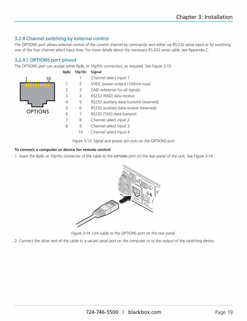
3.2.4 Channel switching by external controlTheOPTIONSportallowsexternalcontrolofthecurrentchannelbycommandssenteitherviaRS-232serialinputorbyswitchingoneofthefourchannelselectinputlines.FormoredetailsaboutthenecessaryRS-232serialcable,seeAppendixC.
3.2.4.1 OPTIONS port pinoutTheOPTIONSportcanaccepteither8p8cor10p10cconnectors,asrequired.SeeFigure3-13.
8p8c 10p10c Signal
1 Channelselectinput1
1 2 5VDCpoweroutput(100mAmax)
2 3 GNDreferenceforallsignals
3 4 RS232(RXD)datareceive
4 5 RS232auxiliarydatatransmit(reserved)
5 6 RS232auxiliarydatareceive(reserved)
6 7 RS232(TXD)datatransmit
7 8 Channelselectinput2
8 9 Channelselectinput3
10 Channelselectinput4
1 10
OPTIONS
4
USERCONSOLE
OPTIONS
Figure3-13.Signalandpowerpin-outsontheOPTIONSport
To connect a computer or device for remote control
1 Insertthe8p8cor10p10cconnectorofthecabletotheOPTIONSportontherearpaneloftheunit.SeeFigure3-14.
Figure3-14.LinkcabletotheOPTIONSportontherearpanel.
2 Connecttheotherendofthecabletoavacantserialportonthecomputerortotheoutputoftheswitchingdevice.

ServSwitch Wizard VGA (USB)
724-746-5500 | blackbox.com Page20 724-746-5500 | blackbox.com
3.2.4.2 Control by RS-232 serialWheretheexternalcontrolisviaRS-232signal,ensurethattheconfigurationmenuoptionOissetto1or3toenableRS-232control.
Serial port parameter settings
Ensurethatthechosenserialportisconfiguredtothefollowing:
• Baudrate: TomatchsettingofBoptionintheConfigurationmenu(defaultis1200).
• Databits: 8
• Stopbit: 1
• Parity: None
Serial port channel selection codes
ASCII Character Hex Decimal
• Channel1: ‘1’ 0x31 49
• Channel2: ‘2’ 0x32 50
• Channel3: ‘3’ 0x33 51
• Channel4: ‘4’ 0x34 52
Note: As each channel is chosen using the above RS-232 commands, the peripherals that will be transferred are determined by the current setting of the switching mode.
3.2.4.3 Control by channel select input linesWheretheexternalcontrolisviathefourchannelselectinputlinesoftheOPTIONSport(seepinoutopposite),ensurethattheconfigurationmenuoptionOissetto3toenabletheinputlines.
Thefourinputlinesaresuitableforconnectiontodrycontactsoropencollectorstyleoutputs.ConnectinganinputlinetoGNDwillcausetheServSwitchWizardVGA(USB)toswitchallofitsfunctionstotheselectedchannel:
• Channel1: Channelselectinput1low
• Channel2: Channelselectinput2low
• Channel3: Channelselectinput3low
• Channel4: Channelselectinput4low
Iftheinputlineisheldlowthenallotherswitchingrequestsbyothermeanswillbeignoreduntilthelinereturnstoahigh(open)state.
Ifmorethanonelogicinputislow(closed)thenthelowerchannelnumbertakespriority.
Note:Theinputlineshaveonlylimitedprotectionagainstovervoltage.

724-746-5500 | blackbox.com
Chapter 3: Installation
724-746-5500 | blackbox.com Page21
3.2.5 Synchronizing multiple unitsServSwitchWizardVGA(USB)unitscanbeconnectedtogethersothattheyoperateinasynchronizedmanner.Thus,twoKV3004AunitscanbemadetoswitchtwovideoheadsinasimilarmannertoanKV3204A.Additionally,twoKV3204AunitscouldbemadetoresembleanKV3404A,whiletwoKV3404Aunitscouldbecombinedinordertoswitchuptoeightvideoheadssimultaneously.
WheneveranServSwitchWizardVGA(USB)channelisswitched,itsendsanRS232commandoutonitsserialinterface(markedOPTIONSontherearpanel).AServSwitchWizardVGA(USB)unitwillswitchitschannelifitreceivesthesamecommandonitsserialinterface.Consequently,bylinkingtheserialinterfaces,amasterunitmaybemadetoautomaticallyswitchoneormoreslaveunitsasshowninFigure3-15.
ItshouldbenotedthatthesynchronizationcabledeliberatelydoesnothavethetransmitpinoftheSlaveEndconnectorlinkedtothereceivepinoftheMasterEndconnector.TodosowouldcausetheSlaveunittobeabletoswitchtheMasterunit.ThiswouldsetupanendlesscyclicalswitchingsequencethatwouldpreventtheServSwitchWizardVGA(USB)devicesfromoperatingcor-rectly.Formoredetailsabouttheserialsynchronizationcables,seeAppendixC.
4 3 2 1
USB2.0SWITCHED
USB 1
USB 2
5V
2.5A
INDOORUSE
ONLYUSERCONSOLE
OPTIONS
4 3 2 1
USB2.0SWITCHED
USB 1
USB 2
5V
2.5A
INDOORUSE
ONLYUSERCONSOLE
OPTIONS
Slave unit
Master unit
Master monitor
Slave monitor
Computers fitted with multiple video heads
Serial synchronization
cable
Figure3-15.Connectionsforsynchronizingtwounits

ServSwitch Wizard VGA (USB)
724-746-5500 | blackbox.com Page22 724-746-5500 | blackbox.com
1234
USB2.0SWITCHED
USB 1
USB 2
5V
4A
INDOORUSE
ONLY
USERCONSOLE
OPTIONS
V1
V2
V3
V4
Display1
Display2
Display3
Display4
Computer1
EDID
Computer2
EDID
Computer3
EDID
Computer4
EDID
3.2.6 Managing EDID video display informationWheneveraServSwitchWizardVGA(USB)unitispoweredon(orwhentheoptionF 2isselectedfromtheconfigurationmenu),itwillinterrogatetheconnectedmonitor(s)todeterminewhetherEDID(ExtendedDisplayIdentificationData)informationisavail-able.IfEDIDinformationisavailable,itwillbecopiedandused;otherwiseadefaultsetofdata,storedwithintheServSwitchWizardVGA(USB),willbesubstituted.YoucanalsooptionallychoosetopreventtheunitfromseekingnewEDIDinformationandinsteadrelyonlyonstoreddata.
EDID Emulation
TheServSwitchWizardVGA(USB)unitsuseanEDID EmulationfeaturetoensurethatthecollectedEDIDinformation(uptotwopages)iscorrectlysuppliedtoeveryconnectedcomputer,whetheritiscurrentlyselectedornot.SeeFigure3-16.
Figure3-16.HowEDIDinformationisdisseminatedacrossthecomputers
3.2.6.1 Refreshing EDID information during useYoucanrefreshtheEDIDinformationfromtheconnectedmonitor(s)withouttheneedtopowercycletheServSwitchWizardVGA(USB).
To refresh EDID information during use
1 EntertheConfigurationmenu(seeSection4.1fordetails).
2 PressFtoentertheFunctionsmenu
3 Press2andthenEnter.
4 PressEandthenEntertoexitthemenu.
3.2.6.2 Using stored EDID information onlyYoucanchoosetopreventtheunitfrominterrogatingthevideodisplay(s)duringstartup.Whenyouinvokethisoption,theunitwillonlyusetheEDIDinformationthatithasalreadystoredandpassthisontotheconnectedcomputers.Toreverttointerrogat-ingthevideodisplay,usetheF 2functiondiscussedabove.
To use the stored EDID information at the power up
1 EntertheConfigurationmenu(seeSection4.1fordetails).
2 PressFtoentertheFunctionsmenu
3 Press3andthenEnter.
4 PressEandthenEntertoexitthemenu.

724-746-5500 | blackbox.com
Chapter 4: Configuration
724-746-5500 | blackbox.com Page23
4. Configuration
4.1 Using the Configuration MenuTheconfigurationmodeallowsyoutodeterminenumerousaspectsoftheServSwitchWizardVGA(USB)unitcapabilities.
To use the configuration menu
Duringnormaluse,thesevensegmentdisplayonthefrontpanelshowsthenumberofthecurrentlyselectedcomputerchannel.Fromthiscondition,enterconfigurationmodeasfollows:
1 PressandholdthefrontpanelCOMPUTERbuttonforroughlyfiveseconds.The display will show:C
2 Onthekeyboard,presstheletterkeyfortherequiredmenusection,e.g.S (seeTable4-1forfulllistofoptions)The display will show the pressed letter.
3 Pressthenumberoftherequiredsetting,e.g.4The display will show the pressed number.
4 PressEntertoacceptthesettingandreturntothemainmenusection.The display will show:C
5 Youcannowcontinuewithyournextconfigurationchange(gotostep2),orexitfromtheconfigurationmenu(seebelow).
To exit the configuration menu and save changes
• PressEandthenpressEntertoexitandsavechanges.
To exit the configuration menu without saving
• Presseitherofthefrontpanelbuttons.

ServSwitch Wizard VGA (USB)
724-746-5500 | blackbox.com Page24 724-746-5500 | blackbox.com
Table4-1.Configurationmenuoptions Letter Number Description
B EntertheOPTIONSportBaudratemenu 1 1200(default) 2 2400 3 9600 4 19200 5 38400 6 57600 7 115200
F EntertheFunctionsmenu 1 Showcurrentfirmwareversion 2 RefreshEDIDinformationfromtheconnectedvideodisplay(default) 3 UsethestoredEDIDatstartup,donotinterrogatethevideodisplay 8 Resetconfigurationtofactorydefaults( isdisplayedmomentarily)
H EntertheHotkeymenu 1 Ctrl+Alt(default) 2 Ctrl+Shift 3 Alt+Shift 4 RightAlt 5 Alt 6 LeftCtrl+Alt 7 RightCtrl+Alt 8 Hotkeysdisabled
O EntertheOptionsportbehaviormenu 1 ChannelswitchingviaRS-232serialcontrol(usingthebaudratesetbythe‘B’option).Contact
switchingviatheOptionsportdisabled.(default) 2 Channelswitchingviaremote.Contactswitchingdisabled(reservedforfutureuse). 3 Asper1butwithcontactswitchingenabled.
P Setanewpasswordforusewiththelockmode
S EntertheSwitchModemenu 1 All(default) 2 KVM+Speaker 3 KVMonly 4 Speakeronly 5 USB1only 6 USB2only
T EntertheAutoscanTimeDelaymenu 1 Autoscandisabled 2 2seconds 3 5seconds(default) 4 7seconds 5 15seconds 6 30seconds 7 1minute 8 5minutes
U EntertheUserPreferencesmenu 1 Enablemouseswitching(default) 2 Disablemouseswitching 7 Cycleallports(whenusing‘Hotkey+Tab’or‘Autoscan’)(default) 8 Cycleonlyactiveports(whenusing‘Hotkey+Tab’or‘Autoscan’)

724-746-5500 | blackbox.com
Chapter 4: Configuration
724-746-5500 | blackbox.com Page25
4.2 General configuration
4.2.1 Changing hotkeysServSwitchWizardVGA(USB)unitsuse CTRL and ALT as their standard hotkeys. These can be changed if they clash with other software or hardware within the installation.
To change the hotkeys
1 EntertheConfigurationmenu(seeSection4.1fordetails).
2 PressHtoentertheHotkeymenuandthenpresseither:
1tochooseCtrl + Alt
2tochooseCtrl + Shift
3tochooseAlt + Shift
4tochooseRight Alt
3 PressEntertoacceptthesettingandreturntothemainmenusection.
4 PressEandthenEntertoexitthemenuandsavechanges.
4.2.2 Mouse switchingYoucanenableordisablemouseswitchingtosuityourinstallationrequirements.
To enable/disable mouse switching
1 EntertheConfigurationmenu(seeSection4.1fordetails).
2 PressUtoentertheUser Preferencesmenuandthenpresseither:
1toEnable mouse switching
2toDisable mouse switching
3 PressEntertoacceptthesettingandreturntothemainmenusection.
4 PressEandthenEntertoexitthemenuandsavechanges.
4.2.3 OPTIONS port speedYoucanchangethespeedoftheOPTIONSserialport.
To change the OPTIONS port speed
1 EntertheConfigurationmenu(seeSection4.1fordetails).
2 PressBtoentertheBaud ratemenuandthenpresseither:
1tochoose1200
2tochoose2400
3tochoose9600
4tochoose19200
3 PressEntertoacceptthesettingandreturntothemainmenusection.
4 PressEandthenEntertoexitthemenuandsavechanges.

ServSwitch Wizard VGA (USB)
724-746-5500 | blackbox.com Page26 724-746-5500 | blackbox.com
4.2.4 OPTIONS port channel control behaviorYoucandeterminehowtheOPTIONSportrespondstochannelcontrolinputs.
To define the OPTIONS port behavior
1 EntertheConfigurationmenu(seeSection4.1fordetails).
2 PressOtoentertheOptions portmenuandthenpresseither:
1toallowchannelswitchingcommandstobereceivedviaRS-232serialsignalthroughtheOPTIONSport(seeAppendixCforcablepin-outdetailsandseeSection3.2.5Channelswitchingbyexternalcontrolforcommanddetails).ThebaudratecurrentlysetbytheBoptionwillbeusedfortheport.SwitchingcommandsviathefourchannelselectinputswithintheOPTIONSportconnectoraredisabledinthismode.Useoption3ifyouwishtoenablethechannelselectinputsinadditiontoRS-232control.
3enableschannelswitchingviaRS-232asperoption1.However,inthismodethefourchannelselectinputsarealsoenabled.
3 PressEntertoacceptthesettingandreturntothemainmenusection.
4 PressEandthenEntertoexitthemenuandsavechanges.
4.2.5 Switching modeUsingtheconfigurationmenu,youcandefineadefaultswitchingmode.Theswitchingmodedetermineswhichperipherals(KVM,USB1,USB2and/orspeakers)shouldbemovedtothenextcomputerwhenitisselectedusinganyofthestandardmeth-ods.Regardless of the default switching mode set here, during use you can always change the mode using either the MODE but-ton (on the front panel) or using the additional hotkey press combinations.
Note: Of the external switching methods, the RS-232 serial signal input will switch the peripherals as defined by the currently selected switching mode. However, switching control initiated by the channel select input lines will always switch all of the periph-erals to the chosen channel regardless of the switching mode.
To set the default switching mode
1 EntertheConfigurationmenu(seeSection4.1fordetails).
2 PressStoentertheSwitch Modemenuandthenpresseither:
1toselectAll(default)
2toselectKVM and speaker
3toselectKVM only
4toselectSpeaker only
5toselectUSB1 only
6toselectUSB2 only
3 PressEntertoacceptthesettingandreturntothemainmenusection.
4 PressEandthenEntertoexitthemenuandsavechanges.

724-746-5500 | blackbox.com
Chapter 4: Configuration
724-746-5500 | blackbox.com Page27
4.2.6 Miscellaneous functionsTo refresh EDID information from the monitor
1 EntertheConfigurationmenu(seeSection4.1fordetails).
2 PressFtoentertheFunctionsmenu
3 Press2andthenEnter.
4 PressEandthenEntertoexitthemenuandsavechanges.
To use the stored EDID information at the power up
Whenyouengagethismode,theunitwillnotinterrogatethevideodisplayduringstartupandwillinsteadusethedatathatarestored.Toreverttointerrogatingthevideodisplay,usetheF2functiondiscussedabove.
1 EntertheConfigurationmenu(seeSection4.1fordetails).
2 PressFtoentertheFunctionsmenu
3 Press3andthenEnter.
4 PressEandthenEntertoexitthemenuandsavechanges.
To reset configuration to factory defaults
1 EntertheConfigurationmenu(seeSection4.1fordetails).
2 PressFtoentertheFunctionsmenu
3 Press8andthenEnter.Thedisplaywillshowrmomentarily.
4 PressEandthenEntertoexitthemenuandsavechanges.
To show the current firmware version
1 EntertheConfigurationmenu(seeSection4.1fordetails).
2 PressFtoentertheFunctionsmenu
3 Press1andthenEnter.
Thedisplaywillblankforashortwhileandthenthemajornumberofthefirmwarerevisionwillbeshown.Thedisplaywillblankagainandthenshowthefirstdigitoftheminornumber.Followinganotherblank,theseconddigitoftheminornumberwillbedisplayed.e.g.<blank> 1 <blank> 0 <blank> 2 <blank> equals v1.02
4 PressEandthenEntertoexitthemenuandsavechanges.
To set a new password
1 EntertheConfigurationmenu(seeSection4.1fordetails).
2 PressPandthenEnter.Thedisplaywillshow
3 EnteranewpasswordandthenEnter.See5.2LockingAccesstotheComputers.
4 PressEandthenEntertoexitthemenuandsavechanges.

ServSwitch Wizard VGA (USB)
724-746-5500 | blackbox.com Page28 724-746-5500 | blackbox.com
4.3 Performing upgradesTheServSwitchWizardVGA(USB)unitisfullyupgradableviaflashupgrade.SuchupgradesrequireaWindows-basedcomputersystemtobelinkedviatheOPTIONSport.
Items required to perform an upgrade
• Optionalupgradecable(seeAppendixCforpin-outspecifications).
• AWindows-basedupgradecomputerwithanRS232serialport.
• ThelatestversionoftheKVMFirmwareUploaderandfirmwarefilesfortheServSwitchWizardVGA(USB)unit(availablefromBlackBoxTechnicalSupport—[email protected]).
To use the KVM Firmware Uploader utility
1 DownloadthelatestServSwitchWizardVGA(USB)unitKVMFirmwareUploaderfromBlackBoxTechnicalSupportandinstallitonaWindowsbasedupgradecomputerthatwillbeconnectedtotheServSwitchWizardVGA(USB)unit.Thefilesaresup-pliedasacompressedZIPfile.DecompresstheZIPfilewithanappropriatetoolsuchasWinZip(www.winzip.com)andcopyallcontainedfilestothesamefolderontheupgradecomputer.
2 Removethepowersupplyplugfromtherearpaneloftheunit.
3 ConnecttheserialportoftheupgradecomputertotheOPTIONSportontherearpaneloftheunitusingtheoptionalupgradecable.Thereisnoneedtoadjustthecomputer’sserialportsettingsastheapplicationwilldothisautomatically.
4 Whilepoweringonorwhenalreadypowered:PressandholdtheCOMPUTERandMODEbuttons(foruptotenseconds)untilthenumericindicatorshows’U’.
5 Fromthefoldercreated/usedinstep1,selecttheKVMUploaderfile/icontoruntheupgradeutility.TheKVMFirmwareUploaderdialogwillbedisplayed:
Figure4-1.KVMFirmwareUploaderutilityscreen.
6 ClicktheQuery UnitbuttontoconfirmthatcommunicationispossiblewiththeServSwitchWizardVGA(USB)unitandtoestablishitsfirmwaredetails.Ifsuccessful,the‘Unitconnected’fieldshouldshowthenameoftheServSwitchWizardVGA(USB)unitandthecurrentfirmwarewillalsobelisted.
IftheapplicationcannotcontacttheServSwitchWizardVGA(USB)unit,re-checktheconnectioncableandclicktheAdvanced...buttontocheckthatthecorrectserialportisbeingused.ChangetheserialportwithintheAdvanced...section,ifnecessary.

724-746-5500 | blackbox.com
Chapter 4: Configuration
724-746-5500 | blackbox.com Page29
7 FromthemainKVMFirmwareUploaderdialog,clicktheBrowse...buttonandselecttheupgradefile:
VGAUSB_xxx.txt
where xxx is the firmware version.
Theupgradefiledetailswillbedisplayedwithinthedialog.
IMPORTANT: Check that the ‘Intended Target Units’ field matches the ‘Unit Connected’ field. If these fields do not match then you may have an incorrect upgrade file, check with Black Box Technical Support before proceeding. Check also that the ‘New firmware version’ is greater than the ‘Current firmware version’. See Figure 4-2.
Figure 4-2. KVMFirmwareUploaderutilityscreenwithupgradefileselected.
8 Tobegintheupgradeprocess,clicktheUpload Nowbutton.Theprogresswillbeshownwithinthedialog.Shouldyoudecidenottocontinuewiththeuploadatanystage,clicktheAbortbutton;responsetothisisusuallyimmediate,however,duringanerasecommand,theuploadwillnotbeaborteduntiltheeraseiscomplete(thismaytakeafewseconds).
9 Disconnectthepower.Whenthepowerisre-appliedtheServSwitchWizardVGA(USB)unitwilloperateusingthenewfirmware.
Issues to consider when performing flash upgrades
Theupgradeprogramrewritestheinternalfirmwarecode.Iftheupgradeprocessisinterruptedthentheunitwillhaveinvalidcodeandwillnotbeabletooperate.Itisthereforegoodpracticetoensurethattheupgradeprocessisalwaysfullycompleted.Apartialorfailedupgrademayberectifiedbyperforminganotherupgrade.
WARNING:RunningfaultyorpartiallyupgradedcodemayhaveunpredictableresultsandmaydamageyourServSwitchWizardVGA(USB)unitorcomputingequipment.
Check that the ‘Intended Target Units’ field matches the ‘Unit Connected’ field.
Check also that the ‘New firmware version’ is greater than the ‘Current firmware version’.

ServSwitch Wizard VGA (USB)
724-746-5500 | blackbox.com Page30 724-746-5500 | blackbox.com
5. Operation
5.1 Selecting a computerTherearefourmainwaystoswitchthecommonperipheralstospecificcomputerchannels:
• Usingthefrontpanelcontrols(seebelow)
• Usinghotkeys
• Usingmousebuttonpresses
• Usingexternalswitchingcontrol(RS-232orinputlines)
5.1.1 Selecting a computer using the front panelThefrontpanelallowsyoutodeterminehowthevariousperipheralsareswitchedtooneormorecomputerchannels.
KVM SPK USB1 USB2MODE
MODE
MODE
MODE
MODE
Will switch all peripherals together
Will switch keyboard, video, mouse and speakers
Will switch only the keyboard, video and mouse
Will switch only the speakers
Will switch only USB peripheral 1
Will switch only USB peripheral 2
COMPUTER KVM
V1
SPK
V2
USB1
V3
USB2
V4
MODE Use this button to choose which peripherals will be switched
The KVM, SPK, USB1, and USB2 indicators show which peripherals are switched to the current computer channel OR (as you begin pressing the MODE button) the peripherals that will be switched during the next press(es) of the COMPUTER button.
Use this button to choose the next required computer
Indicates the number of the currently selected computer
Multiscreen models only - The V1 to V4 indicators show which video monitors are switched to the current computer channel.
Figure5-1.Frontpanelbuttonsandindicators.
To select a computer using the front panel
1 Optional:Ifyouneedtoselectivelyswitchsomeofyourperipherals,presstheMODEbuttonrepeatedlytochangetheswitch-ingmode:
Figure5-2.ChangingtheswitchingmodeusingtheMODEbutton.
Note: If an indicator flashes, it signifies that the respective peripheral is currently switched to another computer channel.
2 PresstheCOMPUTERbuttonrepeatedlytoselecttherequiredcomputerchannel.

724-746-5500 | blackbox.com
Chapter 5: Operation
724-746-5500 | blackbox.com Page31
5.1.2 Selecting a computer using hotkeysUsinghotkeycombinations,youcanquicklyswitchthekeyboard,videomonitor(s),mouseandspeakersandUSBperipheralstoanycomputerchannel.
Therearetwomainswaystousehotkeys:StandardandAdditional.
To use standard hotkey press combinations
Thestandardhotkeypresscombinationsallowyoutochangechannelswiththeminimumofkeypresses:
1 SimultaneouslypressandholdCTRLandALT(orotherhotkeys,ifaltered).
2 WhilestillholdingCTRLandALT,pressthenumberkeyoftherequiredchanneladdress(ortheTABkey),thenreleaseallofthekeys.
Note: The numbers on your keyboard’s numeric keypad are not valid, use only the numeral keys above the QWERTY section.
Theports(KVM,audioand/orUSB)thatareswitchedusingthismethoddependupontheswitchingmodethatiscurrentlysetusingthefrontpanelbuttons.
Therangeofstandardhotkeycombinationsareasfollows:
Note:Ifyourhotkeyshavebeenchanged,substitutethemforCTRLandALTintheexamplesgivenhere.
CTRLALT 1 Selectschannel1
CTRLALT 2 Selectschannel2
CTRLALT 3 Selectschannel3
CTRLALT 4 Selectschannel4
CTRLALT 0 Isolatestheuserconsolefromallchannels
CTRLALT TAB Selectsthenextchannel(seenotebelow)
Choosing which computers are accessed when using hot keys + tab
The computer channels that are visited when you use the hot keys + tab (or mouse buttons/autoscan) are determined by a setting within the Configuration menu:
1 Enter the Configuration menu (see Section 4.1 for details).
2 Press U and then press either:
7 to choose Cycle all ports, or
8 to choose Cycle only active ports
3 Press Enter to accept the setting and return to the main menu section.
4 Press E and then Enter to exit the menu and save changes.

ServSwitch Wizard VGA (USB)
724-746-5500 | blackbox.com Page32 724-746-5500 | blackbox.com
To use additional hotkey press combinations
Inadditiontothestandardhotkeypresscombinations(shownleft),youcanalsoaddadditionalkeypressesinordertodeterminewhichperipheralsareswitched:
1 SimultaneouslypressandholdCTRLandALT.
2 Pressandreleaseacommandkey:
Ato switch all peripherals
Kto switch only the keyboard, video and mouse
Sto switch only the speakers
Uto switch only USB1 and USB2
3 Pressandreleasetherequiredchannelnumber(1to4usingonlythekeysabovetheQWERTYsection).
4 ReleaseCTRLandALT.
Theappropriateperipheralswillchangetothechosenchannel.
Note: Regardless of which peripherals were switched, the front panel indicators will continue to show the switching mode that was last determined using the front panel controls.
5.1.3 Selecting a computer using the mouse buttonsUsingthemousebuttons,youcanquicklyswitchthekeyboard,mouse,videomonitor(s),speakersand/orUSBperipheralstoanycomputerchannel.
Note: These procedures work only with three-button or IntelliMouse devices and only if the ‘Mouse Switching’ option has been enabled.
To select a computer using the mouse buttons
1 Holddownthemiddlebutton(orscrollwheel)ofthemouse.
2 Clicktheleftmousebuttontoincrementthechannelnumberorclicktherightmousebuttontodecrementthechannel.Whenthecorrectchannelisreached,releasethemiddlebutton.
Whenusingthismethodofswitching:
• Thecomputerchannelsthatarevisiteddependupontheconfigurationmenusetting(seenotebelow).
Choosing which computers are accessed when using mouse buttons
The computer channels that are visited when you use the mouse buttons (or hotkeys + tab/autoscan) are determined by a setting within the Configuration menu:
1 Enter the Configuration menu (see Section 4.1 for details).
2 Press U and then press either:
7 to choose Cycle all ports, or
8 to choose Cycle only active ports
3 Press Enter to accept the setting and return to the main menu section.
4 Press E and then Enter to exit the menu and save changes.
• Theports(KVM,audioand/orUSB)thatareswitchedusingthismethoddependupontheswitchingmodethatiscurrentlysetusingthefrontpanelbuttons.

724-746-5500 | blackbox.com
Chapter 5: Operation
724-746-5500 | blackbox.com Page33
5.2 Locking access to the computersWhenprivacyisrequired,youcanlockaccesstotheconnectedcomputersviatheunit.
To lock the unit
1 SimultaneouslypressandholdCTRLandALT(orotherhotkeys,ifaltered).
2 WhilestillholdingCTRLandALT,pressL.
ThedisplaywillshowP(providingavalidpasswordhasbeenpreviouslyset).Youwillnotbeabletoaccessanycomputersuntilthepasswordiscorrectlyentered.
To unlock the unit
• Whenprompted,enterthecorrectpasswordandpressEnter.
To set a new password
1 EntertheConfigurationmenu(seeSection4.1fordetails).
2 PressPandthenEnter.Thedisplaywillshow
3 EnteranewpasswordandthenEnter.
Thepasswordisnotcasesensitiveandcanbeanycombinationofkeystrokes,includingthefunctionkeys,butexcludingtheNumLock,CapsLock,ScrollLockandEnterkeys.Ifyourkeyboardhasspecialmediakeys,thesealsocannotbeusedaspartofthepassword.
Whenyouhavetypedinyourpassword,pressEntertostoreit.Don’tworryifyoutypethepasswordincorrectly,youcanalwaysre-enterconfiguremodeandsetthepasswordagain.
4 PressEandthenEntertoexitthemenuandsavechanges.
To cancel the password
1 EntertheConfigurationmenu(seeSection4.1fordetails).
2 PressPandthenEnter.Thedisplaywillshow
3 PressEntertoremovetheexistingpassword.
4 PressEandthenEntertoexitthemenuandsavechanges.
If you forget the password
Toclearanexistingpassword:ConnecttheOPTIONSportoftheunittotheserialportofacomputerandtransmitthetextclrpwdtotheunit.

ServSwitch Wizard VGA (USB)
724-746-5500 | blackbox.com Page34 724-746-5500 | blackbox.com
5.3 AutoscanningWhenenabled,theautoscanmodeswitchesbetweentheconnectedcomputersinsequence.Thisisusefultoallowyoutosampleactivityamongtheconnectedcomputers.
Twoscanningmodesareavailable:
• Cycle all ports–Thismodevisits,inturn,toeachconnectedcomputer.Thismodeshouldbeusedwithcareduetothereasonsgiveninthewarningbelow.Toprepareforthisautoscanmode,chooseU 7withintheconfigurationmenu.
• Cycle only active ports–Onlycomputerportswhereanactivecomputerisdetectedwillbeviewed.Thismodeavoidsblankscreensfrombeingdisplayedandhelpstopreventtheviewingmonitorfromenteringapower-downstateoneveryscancycle.
Additionally,whenthismodeisselected,wheneveryouuseeitherthemousebuttonsorhotkeys+tabtochangechannels,onlycomputersthatareactivewillbevisited.Toprepareforthisautoscanmode,chooseU 8withintheconfigurationmenu.
WARNING: Many monitors are fitted with automatic power saving relays that switch off after a few seconds when connected to an inactive computer. If you are using such a monitor, do not use the ‘Cycle all ports’ mode. Continual switching on and off of the monitor’s relay will eventually damage the monitor.
Sevenautoscanperiodsareavailable(thetimespentviewingeachcomputer)rangingfrom2secondsto5minutes.Topreparetheautoscanperiod,chooseTandthen2to8withintheconfigurationmenu.
Tostartautoscanningmode,pressCTRL ALT Xonthekeyboard.
To select an autoscan mode
1 EntertheConfigurationmenu(seeSection4.1fordetails).
2 PressUandthenpresseither:
• 7tochooseCycle all ports,or
• 8tochooseCycle only active ports
3 PressEntertoacceptthesettingandreturntothemainmenusection.
4 PressEandthenEntertoexitthemenuandsavechanges.
Note: The setting of this option also affects which computers are visited when the channel is changed using the mouse buttons or hot key + tab.
To select an autoscan period
1 EntertheConfigurationmenu(seeSection4.1fordetails).
2 PressTandthenpresseither:
1tochooseAutoscan disabled,
2tochoose2 seconds,
3tochoose5 seconds,
4tochoose7 seconds,
5tochoose15 seconds,
6tochoose30 seconds,
7tochoose1 minute,or
8tochoose5 minutes.
3 PressEntertoacceptthesettingandreturntothemainmenusection.
4 PressEandthenEntertoexitthemenuandsavechanges.

724-746-5500 | blackbox.com
Chapter 5: Operation
724-746-5500 | blackbox.com Page35
To start autoscanning
• Onthekeyboard,pressCTRLALT X.
Notes:
During autoscanning, mouse switching, hot key + tab and interactivity with the computers are all disabled.
During autoscanning, only the KVM and speaker ports are switched to each visited computer channel, the two USB device ports remain connected to their currently selected channels.
To stop autoscanning
Youcanstoptheautoscanningprocessineitherofthefollowingways:
• PresstheCOMPUTERbuttononthefrontpanel,or
• Selectaspecificchannelusingthehotkeys+channelnumber.

ServSwitch Wizard VGA (USB)
724-746-5500 | blackbox.com Page36 724-746-5500 | blackbox.com
Appendix A. What is True Emulation?TrueEmulationrepresentsasignificantbreakthroughinsharingUSBdevicesbetweentwoormorecomputersystems.Untilthispoint,theproblemhasbeenhowtocreateaUSBswitchthatprovidesallofthefollowing:
• Quick,transparentandreliableswitching,
• AccuraterepresentationoftheconnectedUSBkeyboardandmouse,
• SwitchingcontrolviatheconnectedUSBkeyboardand/ormouse.
ThedifficultyinachievingalloftheaboverequirementshasbeenduetothecomplexityoftheUSBstandard.Thishasledtovari-ousproblemsthathavespawnedanumberofpossiblesolutions.
A.1 Enumerated USB switchingTheearliestattemptstoswitchUSBdevicesappliedarelatively‘handsoff’approach.EnumeratedUSBswitchesaretheelectronicequivalentofthoseoldmechanicalKVMswitcheswithalargeknobonthefront.
EnumeratedswitchesaresocalledbecauseaconnectedUSBdevicewillberequiredtoperformafullinitiation(aprocesscalledEnumeration)everytimeitisswitched;justasifyouhadpulledouttheplugandthenreconnectedit.
EnumeratedswitchessimplypassallsignalsstraightthroughbetweentheUSBdeviceandthecomputer,theydonotattempttointerpretanydata.Formostdevices,thisoffersanadvantagebecausetheswitchjustleavesthemtogetonwiththeirjobswith-outanyinterferenceoranyhitonperformance.However,itmeansthataUSBkeyboardormousecannotbeusedtocontroltheswitchingprocess-aquickandsimplecontrolmethodexpectedbymostusers.Reliabilityofswitchingisalsoanissuethathasplaguedenumeratedswitches,especiallywhenusedwithcertainUSBdevicesandparticularoperatingsystems.
A.2 Emulated USB switchingTheissueswithinterpretingthecomplexUSBdatastreamsandrecreating(orEmulating)theidentityofattachedUSBdeviceswereeventuallysolved,leadingtothecreationoftheEmulatedUSBswitch.
AneatsideeffectofthetechniqueusedisthateachcomputercanbefooledintothinkingthattheUSBdeviceispermanentlyconnectedtoit,evenwhenthedeviceisswitchedtoanothercomputer.ThismeansthattheenumerationprocessfortheUSBdevicetakesplaceonlyonce,duringthefirstpoweron.Afterthat,acomputermerelyseesadormantversionoftheUSBdevicewheneverthedeviceisactuallyconnectedtoadifferentcomputer.
However,itremainsacomplextasktodynamicallyassumetheidentityofaUSBdevice,distributeitamongtheconnectedcom-putersandmaintainallofthenecessarysignals,statesandprocesses.Therefore,manufacturershavepreviouslyrelieduponafixedkeyboardandmouseprofilethatisdeclaredtoeachcomputer,regardlessoftheactualconnecteddevices.Thisprecludedtheuseofanyspecialkeyboardormousefeaturesoverandabovethestandardlayouts.
A.3 True Emulation MindfulofthelimitationsassociatedwiththepreviousUSBswitchingtechniques,wesetaboutcreatingamoreeffectiveandele-gantsolution.Afteragreatdealofresearchanddevelopment,True Emulationistheresult.
TrueEmulationallowsthecompleteidentityofthekeyboardandmousetobecopiedandthenpresentedtoalloftheconnectedcomputers.Thismeansthatanykeyboardofferingspecialistfunctionkeysoranymousewithextrafeatureswillbefullysupportedateachcomputer.Aswiththepreviousemulationmethod,theunselectedcomputerswillcontinuetoseetheidentitiesofthekeyboardandmouse,whichmeansthatnoenumerationisnecessarywhentheirlinkbecomesactiveonceagain.Thisnotonlyhelpstospeeduptherateofreconnection,butalsoraisesthereliabilityofswitchingbecauseUSBlinksareattheirmostvulnera-bleduringtheenumerationprocess.
TrueEmulationreliesuponahighspeedcircuit,calledanEmulationEngine,tofullyemulatetheUSBdeviceidentitiesandalsointerpretkeyboardandmousedatastreams.TheresultisfullsupportforKVMswitchingcontrolviahotkeypressesorthethirdbutton/scrollwheelofamouse.

724-746-5500 | blackbox.com
Appendices
724-746-5500 | blackbox.com Page37
TrueEmulationisnotnecessarilyrequiredbyotherUSBdevices,whichiswhyyouwillalsofindtwoenumeratedcircuitsincluded(showningreenwithintheblockdiagram)alongsidetheTrueEmulationfeature(showninblue).ThisallowsthoseotherUSBdevicestooperateattheirhighestspeeds,withoutanyintervention.TheenumeratedcircuitsbenefitgreatlyfromtheUSBHubsthatarejointlyusedwiththeTrueEmulationsystem.Becausetheyinterfacedirectlyandpermanentlywitheachcomputer,theyhelptostabilizethedormantlinks,makingerrorsduringenumerationmuchlesslikely.
ThedualswitchingarrangementprovidesfurtherflexibilitybecausetheTrueEmulationandenumeratedsectionscanbeswitchedinunisonorindependentlyofeachother,asrequired.Thus,yourvariousperipheralscanoperatewithdifferentcomputersatthesametime.
HOSTCONTROLLER
USBKEYBOARD
OTHER USBDEVICE
USBMOUSE
USBHUB
PC1
PC2
PC3
PC4
USBHUB
USBHUB
USBHUB
EMULATIONENGINE
FigureA-1.TrueEmulationfunctionalblockdiagram.Theemulatedsectionoftheswitchisshowninblueandhandlesonlythekeyboardandmouse.ThegreenenumeratedsectionoftheswitchhandlesotherUSBdevices
andalsousestheUSBhubstolinkwiththecomputers.

ServSwitch Wizard VGA (USB)
724-746-5500 | blackbox.com Page38 724-746-5500 | blackbox.com
Appendix B. Default EDID video modesThefollowingdigitalvideomodesaredefinedwithinthedefaultEDIDinformationheldbytheServSwitchWizardVGA(USB)units.ThisinformationisusedonlyifnonewEDIDinformationismadeavailablebytheattachedvideomonitor(s).TheServSwitchWizardVGA(USB)unitssupportvideoresolutionsandrefreshratesinexcessofthoselistedhere.
1024x768pat60Hz Native/preferredtiming
720x400pat70Hz IBMVGA
720x400pat88Hz IBMXGA2
640x480pat60Hz IBMVGA
640x480pat67Hz AppleMacII
640x480pat72Hz VESA
640x480pat75Hz VESA
800x600pat56Hz VESA
800x600pat60Hz VESA
800x600pat72Hz VESA
800x600pat75Hz VESA
832x624pat75Hz AppleMacII
1024x768iat87Hz IBM
1024x768pat60Hz VESA
1024x768pat70Hz VESA
1024x768pat75Hz VESA
1280x1024pat75Hz VESA
1152x870pat75Hz AppleMacII
1600x1200pat60Hz VESASTD
1680x1050pat60Hz VESASTD
1360x765pat60Hz VESASTD
1360x768pat60Hz
1440x900pat60Hz VESASTD
1280x720pat60Hz VESASTD
1920x1080pat60Hz VESASTD

724-746-5500 | blackbox.com
Appendices
724-746-5500 | blackbox.com Page39
Appendix C. Cable pin-outsTheOPTIONSportusesa10p10csocketwhichcanaccommodateboth10p10cconnectorsaswellasthemuchmorecommon8p8cconnectors,whichareusedonEthernetleadsandpatchcables.Thepin-outsarelistedinthissectionforbothtypesofcon-nector.
6 3TXD RXD
2 2GND GND
Serial remote control and flash upgrade cable (8p8c)
8p8c connector
D-Type female 9 way
Multi-head synchronization cable (8p8c)
MASTER end8p8c connector
SLAVE end8p8c connector
6 2TXD RXD
3
2
3
5
RXD
GND
TXD
GND
Serial remote control and flash upgrade cable (10p10c)
10p10c connector
D-Type female 9 way
7 2TXD RXD
4
3
3
5
RXD
GND
TXD
GND
7 4TXD RXD
3 3GND GND
Multi-head synchronization cable (10p10c)
MASTER end10p10c connector
SLAVE end10p10c connector

ServSwitch Wizard VGA (USB)
724-746-5500 | blackbox.com Page40
Appendix D. Safety information• Foruseindry,oilfreeindoorenvironmentsonly.
• BoththeServSwitchWizardVGA(USB)unitanditspowersupplygenerateheatwheninoperationandwillbecomewarmtothetouch.Donotenclosethemorplacethemlocationswhereaircannotcirculatetocooltheequipment.Donotoperatetheequipmentinambienttemperaturesexceeding40degreesCentigrade.Donotplacetheproductsincontactwithequipmentwhosesurfacetemperatureexceeds40degreesCentigrade.
• Warning-livepartscontainedwithinpoweradapter.
• Nouserserviceablepartswithinpoweradapter-donotdismantle.
• Plugthepoweradapterintoasocketoutletclosetothemodulethatitispowering.
• Replacethepoweradapterwithamanufacturerapprovedtypeonly.
• Donotusethepoweradapterifthepoweradaptercasebecomesdamaged,crackedorbrokenorifyoususpectthatitisnotoperatingproperly.
• IfyouuseapowerextensioncordwiththeServSwitchWizardVGA(USB)unit,makesurethetotalampereratingofthedevic-espluggedintotheextensioncorddoesnotexceedthecord’sampererating.Also,makesurethatthetotalampereratingofallthedevicespluggedintothewalloutletdoesnotexceedthewalloutlet’sampererating.
• DonotattempttoservicetheServSwitchWizardVGA(USB)unityourself.

724-746-5500 | blackbox.com
About Black BoxBlackBoxNetworkServicesisyoursourceformorethan118,000networkingandinfrastructureproducts.You’llfindeverythingfromcabinetsandracksandpowerandsurgeprotectionproductstomediaconvertersandEthernetswitchesallsupportedbyfree,live24/7Techsupportavailablein20secondsorless.
©Copyright2010.Allrightsreserved.BlackBox®andtheDoubleDiamondlogoareregisteredtrademarksofBBTechnologies,Inc.Anythird-partytrademarksappearinginthisdocumentareacknowledgedtobethepropertyoftheirrespectiveowners.
Black Box Tech Support: FREE! Live. 24/7.
Great tech support is just 20 seconds away at 724-746-5500 or blackbox.com.
®
NETWORK SERVICES
®
Tech support theway it should be.