utp vga video splitter -...
TRANSCRIPT

4-port UTP VGA VideoSplitter/Extender
ST124UTPST124UTPLRRST124UTPR
Instruction Guide
The Professionals’ Source For Hard-to-Find Computer Parts
UTP VGA VIDEOSPLITTER
* Actual product may vary from photo

1
Table of Contents Welcome 2
1. Introduction 3 2. The system components 3 3. The Central Unit 5 4. The Remote Long Range Unit 5 5. The Remote Short Range Unit ports 6 6. The cables 7 7. Connecting the System cables 7 8. Connecting the Screen cable 8 9. Connecting monitors to the Remote Units 8 10. Connecting a local KVM console 8 11. Connecting to the Power supply 8 12. The UTP Video Splitter Remote Long Range unit 10
The dipswitches 11 13. Operating the UTP VGA Splitter system 12
Adjusting the screen picture 12 For the Long Range Remote Unit – Adjusting the brightness 12
14. Technical Specifications 13

FCC COMPLIANCE STATEMENTThis equipment has been tested and found to comply with the limits for a Class Adigital device, pursuant to part 15 of the FCC Rules. These limits are designed toprovide reasonable protection against harmful interference in a residential installation.This equipment generates, uses and can radiate radio frequency energy and, if notinstalled and used in accordance with the instructions, may cause harmful interferenceto radio communications. However, there is no guarantee that interference will notoccur in a particular installation.
If this equipment does cause harmful interference toradio or television reception, which can be determined by turning the equipment offand on, the user is encouraged to try to correct the interference by one or more of thefollowing measures:
• Reorient or relocate the receiving antenna.• Increase the separation between the equipment and receiver.• Connect the equipment into an outlet on a circuit different from that to which the
receiver is connected.• Consult the dealer or an experienced radio/TV technician for help.
Technical precautionsThis equipment generates radio frequency energy and if not installed in accordance withthe manufacturer's instructions, may cause radio frequency interference.
This equipment complies with Part 15, Subpart J of the FCC rules for a Class Acomputing device. This equipment also complies with the Class A limits for radio noiseemission from digital apparatus set out in the Radio Interference Regulation of theCanadian Department of Communications.
These above rules are designed to provide reasonable protection against such interfer-ence when operating the equipment in a commercial environment. If operation of thisequipment in a residential area causes radio frequency interference, the user, and notStarTech.com, will be responsible.
Changes or modifications made to this equipment not expressly approved byStarTech.com could void the user's authority to operate the equipment.StarTech.comassumes no responsibility for any errors that appear in this document. Information in thisdocument is subject to change without notice.

3
1. Introduction With the UTP VGA Splitter system, broadcast your computer's VGA screen to four remote monitors simultaneously. Broadcast up to 250m/820ft using CAT5 UTP cables without loosing any picture quality.
The UTP VGA Splitter system is compatible with VGA, SVGA, or XGA video standards
2. The system components The UTP VGA Splitter system components include:
• Central Unit - (2/4 port model)
• 2/4 Remote Units
• 2/4 UTP CAT5 System cables
• Cables (illustrated below)
• Power adapters
The UTP VGA Splitter Central Unit comes with either 2 or 4 ports.
The 2 Port Model can have 2 Remote Units connected to it, while the 4 Port Model can have 4 Remote Units connected.
There are 2 Remote Unit models. The Short Range model can be located up to 110m/360ft away from the computer, and the Long Range model can be 250m/820ft away from the computer.

4
The figure below illustrates the Central Unit 4-port model configuration. The configuration is the same for the 2-port model, except that there are only 2 Remote Units connected.
POWER
LOCAL MONITOR VIDEO IN
TO REMOTE UNITS
1 2
SDP110
Central Unit
Optional keyboard,monitor & mouse
3 4
POWER PICTU RE MONITOR TO CENTRAL UNIT
SDP110
Remote Unit 4
POWER PICTURE MONITOR TO CENTRAL UNIT
SDP110
Remote Unit 3
POWER PICTU RE MONITOR TO CENTRAL UNIT
SDP110
Remote Unit 2
POWER PICTURE MONITOR TO CENTRAL UNIT
SDP110
Remote Unit 1

5
3. The Central Unit The figure below illustrates the Central Unit front panel.
BROADCASTERVGAUTP SPLITTER
BROADCASTERVGAUTP SPLITTERVGAUTP SPLITTER
CENTRAL UNIT
The figure below illustrates the ports on the Central Unit 2 Port rear panel.
POWER
Power connector
Screencable tocomputer
Systemcables toRemote units
LOCAL MONITOR VIDEO IN
TO REMOTE UNITS
1 2
(optional)localmonitor
The Central Unit 4-Port rear panel is the same with the addition of 2 more RJ45 ports.
4. The Remote Long Range Unit The figure below illustrates Remote Long Range Unit front panel.
BROADCASTERVGAUTP SPLITTER
BROADCASTERVGAUTP SPLITTERVGAUTP SPLITTER
REMOTE UNIT
6
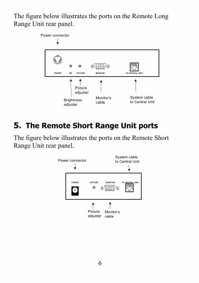
The figure below illustrates the ports on the Remote Long Range Unit rear panel.
POWER
Power connector
Monitor’scable
System cableto Central Unit
MONITOR TO CENTRAL UNIT
Pictureadjuster
BR PICTURE
Brightnessadjuster
5. The Remote Short Range Unit ports The figure below illustrates the ports on the Remote Short Range Unit rear panel.
POWER PICTURE MONITOR TO CENTRAL UNIT
Power connector
Pictureadjuster
Monitor’scable
System cableto Central Unit

7
6. The cables The cables used in the UTP VGA Splitter system are illustrated below.
CAT5 UTP System cable
Screen cable
7. Connecting the System cables The System cable consists of a single 4-pair CAT5 UTP cable, 2 x 4 x 24 AWG. The System cables connect the Remote Units to the Central Unit.
To connect the System cable:
1. Connect one connector to the Central Unit's RJ45 #1 port.
2. Connect the other connector to one Remote Unit’s RJ45 port.
3. Connect another System cable to the other Remote Unit’s System port and the Central Unit's RJ45 #2 port.
4. For the 4 Port Central Unit model connect another 2 Remote Units with System cables to the Central Unit’s RJ45 ports #3 and #4.
8
8. Connecting the Screen cable The Screen cable connects the Central Unit to the computer.
To connect the Screen cable:
1. Connect the HDD15M connector to computer’s video card.
2. Connect the HDD15F connector to the Central Unit 's Video In port.
9. Connecting monitors to the Remote Units To connect monitors to each Remote Unit:
1. Connect the monitor’s connector to Remote Unit’s Monitor port.
10. Connecting a local KVM console You can connect a monitor to the Central unit’s Screen Out port and a keyboard and mouse to the computer. This gives you the ability to update and see the data displayed on the remote screens.
11. Connecting to the Power supply The units come with the following power adapters:
Central Unit 2/4 port – 2 x 9 VAC, 1A from AC/AC adapter
Remote Long Range – 2 x 9 VAC, 1A from AC/AC adapter
Remote Short Range – 9 VAC, 1.5A from AC/AC adapter
Connect each unit to the Power supply with the Power adapter and cord provided.

9
The figure below illustrates the detailed connections of the UTP VGA Splitter system
POWER
LOCAL MONITOR VIDEO IN
TO REMOTE UNITS
1 2
POWER PICTURE MONITOR TO CENTRAL UNIT
SDP110
POWER PICTURE MONITOR TO CENTRAL UNIT
SDP110 SDP110
Central Unit
Remote UnitRemote Unit
CAT5 cableCAT5 cable
Screen cable
Optional keyboard,monitor & mouse
10
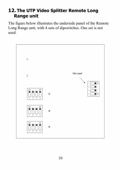
12. The UTP Video Splitter Remote Long Range unit
The figure below illustrates the underside panel of the Remote Long Range unit, with 4 sets of dipswitches. One set is not used.
ON
2 3 41
DIP
ON
2 3 41
DIP
ON
2 3 41
DIP
ON
23
41
DIPG
B
R
Not used
11
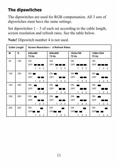
The dipswitches
The dipswitches are used for RGB compensation. All 3 sets of dipswitches must have the same settings.
Set dipswitches 1 – 3 of each set according to the cable length, screen resolution and refresh rates. See the table below.
Note! Dipswitch number 4 is not used.
Cable Length Screen Resolution and Refresh Rates M ft 640x480
75 Hz 800x600 75 Hz
1024x768 75 Hz
1280x1024 75 Hz
50 165 ON OFF 1 2 3
ON OFF 1 2 3
ON OFF 1 2 3
ON OFF 1 2 3
100 330 ON OFF 1 2 3
ON OFF 1 2 3
ON OFF 1 2 3
ON OFF 1 2 3
150 490 ON OFF 1 2 3
ON OFF 1 2 3
ON OFF 1 2 3
ON OFF 1 2 3
200 650 ON OFF 1 2 3
ON OFF 1 2 3
ON OFF 1 2 3
ON OFF 1 2 3
250 820 ON OFF 1 2 3
ON OFF 1 2 3
ON OFF 1 2 3
ON OFF 1 2 3
12
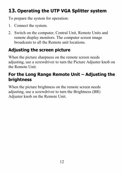
13. Operating the UTP VGA Splitter system To prepare the system for operation:
1. Connect the system.
2. Switch on the computer, Central Unit, Remote Units and remote display monitors. The computer screen image broadcasts to all the Remote unit locations.
Adjusting the screen picture
When the picture sharpness on the remote screen needs adjusting, use a screwdriver to turn the Picture Adjuster knob on the Remote Unit.
For the Long Range Remote Unit – Adjusting the brightness
When the picture brightness on the remote screen needs adjusting, use a screwdriver to turn the Brightness (BR) Adjuster knob on the Remote Unit.

13
14. Technical Specifications
Video output SVGA, VGA, XGA, or Monochrome System cable length With Remote Short Range 110m/360ft With Remote Long Range 250m/820ft Power adapters Central Unit 2/4 port – 2 x 9 VAC, 1A from AC/AC adapter Remote Long Range – 2 x 9 VAC, 1A from AC/AC adapter Remote Short Range – 9 VAC, 1.5A from AC/AC adapter Video signal Analog signal: Red, Green, Blue 0.7Vp-p/ 75 ohms positive Resolution 1024 x 768 Sync TTL Compatible Horizontal sync range Sync positive/ negative Vertical sync range Sync positive/ negative Cables System 4-pair CAT5 UTP: RJ45 / RJ45 connectors. 2 x 4 x 24 AWG Screen: HDD15M / HDD15F connectors Dimensions Central Unit with 2 / 4 Ports: 195 x 100 x 40mm
Remote Short Range Unit: 113 x 90.5 x 40mm
Remote Long Range Unit: 160 x 95 x 40mm
Operating temperature Up to 50ºC/122ºF Storage temperature -40ºC to 70ºC/-40ºF to 158ºF Humidity 80% non condensing relative humidity

Technical Support
The following technical resources are available for this StarTech.com product:
On-line help:We are constantly adding new information to the Tech Support section of our web site. Toaccess this page, click the Tech Support link on our homepage, www.startech.com. In thetech support section there are a number of options that can provide assistance with thiscard.
Knowledge Base - This tool allows you to search for answers to common issues using key words that describe the product and your issue.FAQ - This tool provides quick answers to the top questions asked by our customers.Downloads - This selection takes you to our driver download page where you can find the latest drivers for this product.
Call StarTech.com tech support for help: USA/Canada: 1-519-455-4931UK/Ireland/Europe: 00-800-7827-8324
Support hours: Monday to Friday 9:00AM to 5:00PM EST (except holidays)
Warranty InformationThis product is backed by a one-year warranty. In addition, StarTech.com warrants itsproducts against defects in materials and workmanship for the periods noted below,following the initial date of purchase. During this period, the products may bereturned for repair, or replacement with equivalent products at our discretion. Thewarranty covers parts and labor costs only. StarTech.com does not warrant its productsfrom defects or damages arising from misuse, abuse, alteration, or normal wear andtear.
Limitation of LiabilityIn no event shall the liability to StarTech.com Ltd. (or its officers, directors, employees oragents) for any damages (whether direct or indirect, special, punitive incidental, conse-quential, or otherwise), loss of profits, loss of business, or any pecuniary loss, arising outof related to the use of the product exceed the actual price paid for the product.
Some states do not allow the exclusion or limitation of incidental or consequential dam-ages. If such laws apply, the limitations or exclusions contained in this statement may notapply to you.