control of z‑source inverter topologies for distributed
TRANSCRIPT

This document is downloaded from DR‑NTU (https://dr.ntu.edu.sg)Nanyang Technological University, Singapore.
Control of Z‑source inverter topologies fordistributed generation systems
Chandana Jayampathi Gajanayake
2008
Chandana, J. G. (2008). Control of z‑source inverter topologies for distributed generationsystems. Doctoral thesis, Nanyang Technological University, Singapore.
https://hdl.handle.net/10356/20680
https://doi.org/10.32657/10356/20680
Downloaded on 26 Mar 2022 10:43:57 SGT

CONTROL OF Z-SOURCE INVERTER TOPOLOGIES FORDISTRIBUTED 'GENERATION SYSTEMS
CHANDANAJAYAMPATHIGAJANAYAKE
School of Electrical & Electronic Engineering
A thesis submitted to the Nanyang Technological Universityin fulfillment of the requirement for the degree of '
Doctor of Philosophy
2008
Iiq
Iod
Ioq
I odq
I max
1,Ie, Ici,Ic2IDC
IL_m
I MPP
IpvI scITHD
IzI Zn
lap*lap
Ia,Ip,IoIa *, Ip*,10*
Iah,Iphlin
12n
I;
afJ axis currentafJ axis reference currentafJO axis current componentsafJO axis reference current componentsafJ axis harmonic current componentsNeutral current of inverter 1Neutral current of inverter 2Zero sequence reference current
Average Z-source inductor currentPerturbed Z-source inductor current
Perturbed load currentConstantGain factor of fifth harmonics filterGain factor of seventh harmonics filterGain factor of eleventh harmonics filterDC side controller proportional gain of PI controllerDC side controller integral gain of PI controllerGain of the inverterIntegral gain of PI controller in current controllerGain of the hth resonance filterProportional gain of AC side inner loop controllerProportional gain of PI controller in current controllerProportional gain of zero sequence resonance controllerIntegral gain of the resonance controllerIntegral gain of the zero sequence resonance controllerIntegral gain of the hth resonance controllerProportional gain of AC side PI controllerIntegral gain of the AC side PI controllerMultiplying factor for harmonics eliminationDC side filter inductanceLoad inductanceNeutral inductanceGrid inductanceLeakage inductance of transformer
XVII
ATTENTION: The Singapore Copyright Act applies to the use of this document. Nanyang Technological University Library

To my parents for their encouragement and love
Iiq
Iod
Ioq
I odq
I max
1,Ie, Ici,Ic2IDC
IL_m
I MPP
IpvI scITHD
IzI Zn
lap*lap
Ia,Ip,IoIa *, Ip*,10*
Iah,Iphlin
12n
I;
afJ axis currentafJ axis reference currentafJO axis current componentsafJO axis reference current componentsafJ axis harmonic current componentsNeutral current of inverter 1Neutral current of inverter 2Zero sequence reference current
Average Z-source inductor currentPerturbed Z-source inductor current
Perturbed load currentConstantGain factor of fifth harmonics filterGain factor of seventh harmonics filterGain factor of eleventh harmonics filterDC side controller proportional gain of PI controllerDC side controller integral gain of PI controllerGain of the inverterIntegral gain of PI controller in current controllerGain of the hth resonance filterProportional gain of AC side inner loop controllerProportional gain of PI controller in current controllerProportional gain of zero sequence resonance controllerIntegral gain of the resonance controllerIntegral gain of the zero sequence resonance controllerIntegral gain of the hth resonance controllerProportional gain of AC side PI controllerIntegral gain of the AC side PI controllerMultiplying factor for harmonics eliminationDC side filter inductanceLoad inductanceNeutral inductanceGrid inductanceLeakage inductance of transformer
XVII
ATTENTION: The Singapore Copyright Act applies to the use of this document. Nanyang Technological University Library

Acknowledgment
First and foremost I would like to express my deepest gratitude to my supervisor
Associate Professor. D Mahinda Vilathgamuwa for his continuous encouragement,
invaluable suggestions and guidance given throughout my research work.
My sincere appreciation goes to my co-supervisor, Assistant Professor Poh Chaing
Loh, for his support and continuous interest shown in my research work.
I would like to thank Nanyang Technological university for providing me the
opportunity to pursue my PhD, and providing me with research scholarship.
I sincerely thank fellow research students in Power electronics design lab (PEDL)
and friends for giving lne their friendship and encouragements. Also I would like to
thank technicians in PEDL, Benny and Cristina for giving me technical support.
Some of my work is carried out in Institute of Energy Technology University of
Aalborg. I would like to extend my gratitude to Professor Frede Blaabjerg and
Associate Professor Remus Teodorescu for giving me the opportunity and continuous
encouragement and guidance given me during the stay in Denmark. Also I would like
thank all the colleagues and lab technicians there for their friendship and support.
Finally, I would like to give my special thank to my loving family members for
their understanding, persistent support and encouragement throughout my academic
carner.
Iiq
Iod
Ioq
I odq
I max
1,Ie, Ici,Ic2IDC
IL_m
I MPP
IpvI scITHD
IzI Zn
lap*lap
Ia,Ip,IoIa *, Ip*,10*
Iah,Iphlin
12n
I;
afJ axis currentafJ axis reference currentafJO axis current componentsafJO axis reference current componentsafJ axis harmonic current componentsNeutral current of inverter 1Neutral current of inverter 2Zero sequence reference current
Average Z-source inductor currentPerturbed Z-source inductor current
Perturbed load currentConstantGain factor of fifth harmonics filterGain factor of seventh harmonics filterGain factor of eleventh harmonics filterDC side controller proportional gain of PI controllerDC side controller integral gain of PI controllerGain of the inverterIntegral gain of PI controller in current controllerGain of the hth resonance filterProportional gain of AC side inner loop controllerProportional gain of PI controller in current controllerProportional gain of zero sequence resonance controllerIntegral gain of the resonance controllerIntegral gain of the zero sequence resonance controllerIntegral gain of the hth resonance controllerProportional gain of AC side PI controllerIntegral gain of the AC side PI controllerMultiplying factor for harmonics eliminationDC side filter inductanceLoad inductanceNeutral inductanceGrid inductanceLeakage inductance of transformer
XVII
ATTENTION: The Singapore Copyright Act applies to the use of this document. Nanyang Technological University Library

Table ofcontents
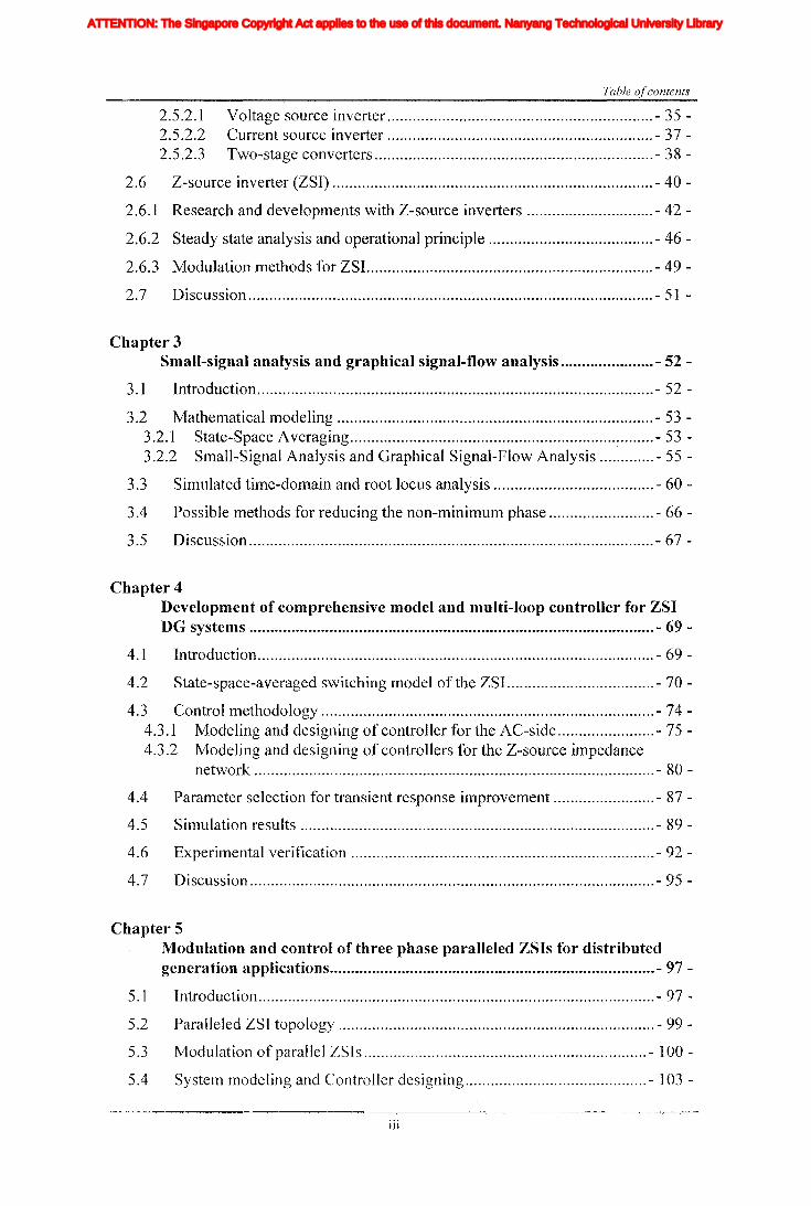
Table of contents
Acknowledgment ......................•................................................................................... i
Table of Contents ii
Summary- vi
List of figures viii
List of tables xiv
Abbreviations xv
List of symboIs xvi
Chapter 1I'ntroduction - 1 -
1.1 Motivation - 1 -
1.2 Objectives - 5 -
1.3 Contributions - 9 -
1.4 Organization of the report - 14 -
Chapter 2A review of distributed generation, selected converter topologies andoperation of ZSI - 17 -
2.1 Introduction - 17 -
2.2 Distributed generation - 17 -
2.3 Energy source for DG - 19 -2.3.1 Fuel cell - 20 -2.3.2 Solar cells - 22 -2.3.3 Wind energy - 23 -2.3.4 Ultra capacitors - 26 -2.3.5 Battery banks - 26 -
2.4 Power quality problems associated with DG - 27 -2.4.] Unbalance - 27 -2.4.2 Faults, sags and interruptions - 29 -2.4.3 Harmonics - 30 -
2.5 Converter topologies for Distributed Generation - 31 -2.5.1 Topologies for mitigating the power quality issues - 31 -
2.5.1.1 UPS - 31 -2.5.1.2 DVR -32-2.5.1.3 APF - 33 -2.5.1.4 SVC - 34 -2.5.1.5 Flexible DG systems - 34 -
2.5.2 DG interfacing topologies - 35 -
11
Iiq
Iod
Ioq
I odq
I max
1,Ie, Ici,Ic2IDC
IL_m
I MPP
IpvI scITHD
IzI Zn
lap*lap
Ia,Ip,IoIa *, Ip*,10*
Iah,Iphlin
12n
I;
afJ axis currentafJ axis reference currentafJO axis current componentsafJO axis reference current componentsafJ axis harmonic current componentsNeutral current of inverter 1Neutral current of inverter 2Zero sequence reference current
Average Z-source inductor currentPerturbed Z-source inductor current
Perturbed load currentConstantGain factor of fifth harmonics filterGain factor of seventh harmonics filterGain factor of eleventh harmonics filterDC side controller proportional gain of PI controllerDC side controller integral gain of PI controllerGain of the inverterIntegral gain of PI controller in current controllerGain of the hth resonance filterProportional gain of AC side inner loop controllerProportional gain of PI controller in current controllerProportional gain of zero sequence resonance controllerIntegral gain of the resonance controllerIntegral gain of the zero sequence resonance controllerIntegral gain of the hth resonance controllerProportional gain of AC side PI controllerIntegral gain of the AC side PI controllerMultiplying factor for harmonics eliminationDC side filter inductanceLoad inductanceNeutral inductanceGrid inductanceLeakage inductance of transformer
XVII
ATTENTION: The Singapore Copyright Act applies to the use of this document. Nanyang Technological University Library
2.5.2.12.5.2.22.5.2.3
Table ofcontents
Voltage source inverter - 35 -Current source inverter - 37 -Two-stage converters - 38 -
2.6 Z-source inverter (ZSI) - 40 -
2.6.1 Research and developments with Z-source inverters - 42 -
2.6.2 Steady state analysis and operational principle - 46 -
2.6.3 Modulation methods for ZSI. - 49 -
2.7 Discussion - 51 -
Chapter 3Small-signal analysis and graphical signal-flow analysis - 52 -
3.1 Introduction - 52 -
3.2 Mathematical modeling - 53 -3.2.1 State-Space Averaging ~ - 53 -3.2.2 Small-Signal Analysis and Graphical Signal-Flow Analysis - 55 -
3.3 Simulated time-domain and root locus analysis - 60 -
3.4 Possible methods for reducing the non-minimum phase - 66 -
3.5 Discussion - 67 -
Chapter 4Development of comprehensive model and multi-loop controller for ZSIDG systems - 69 -
4.1 Introduction - 69 -
4.2 State-space-averaged switching model of the ZSI. - 70 -
4.3 Control methodology - 74 -4.3.1 Modeling and designing of controller for the AC-side - 75 -4.3.2 Modeling and designing of controllers for the Z-source impedance
network - 80 -
4.4 Parameter selection for transient response improvement - 87 -
4.5 Simulation results - 89 -
4.6 Experimental verification r •••••••••••••••••••••••••••••••••••••••• - 92 -
4.7 Discussion - 95 -
Chapter 5Modulation and control of three phase paralleled ZSIs for distributedgeneration applications - 97 -
5.1 Introduction - 97 -
5.2 Paralleled ZSI topology - 99 -
5.3 Modulation of parallel ZSIs - 100 -
5.4 SystelTI modeling and Controller designing - 103 -
iii
Iiq
Iod
Ioq
I odq
I max
1,Ie, Ici,Ic2IDC
IL_m
I MPP
IpvI scITHD
IzI Zn
lap*lap
Ia,Ip,IoIa *, Ip*,10*
Iah,Iphlin
12n
I;
afJ axis currentafJ axis reference currentafJO axis current componentsafJO axis reference current componentsafJ axis harmonic current componentsNeutral current of inverter 1Neutral current of inverter 2Zero sequence reference current
Average Z-source inductor currentPerturbed Z-source inductor current
Perturbed load currentConstantGain factor of fifth harmonics filterGain factor of seventh harmonics filterGain factor of eleventh harmonics filterDC side controller proportional gain of PI controllerDC side controller integral gain of PI controllerGain of the inverterIntegral gain of PI controller in current controllerGain of the hth resonance filterProportional gain of AC side inner loop controllerProportional gain of PI controller in current controllerProportional gain of zero sequence resonance controllerIntegral gain of the resonance controllerIntegral gain of the zero sequence resonance controllerIntegral gain of the hth resonance controllerProportional gain of AC side PI controllerIntegral gain of the AC side PI controllerMultiplying factor for harmonics eliminationDC side filter inductanceLoad inductanceNeutral inductanceGrid inductanceLeakage inductance of transformer
XVII
ATTENTION: The Singapore Copyright Act applies to the use of this document. Nanyang Technological University Library

Table
5.4.1 System modeling and Controller design - 107 -5.4.1.1 AC-side Controller - 107 -5.4.1.2 Inner Current Loop - 109 -5.4.1.3 Reference Current Generator in the Grid Connected Mode - III -5.4.1.4 Outer Voltage Loop - 111 -
5.4.2 DC-side Controller - 113 -
5.5 Simulation results - 114 -5.5.1 Simulation results for grid connected operation - 115 -5.5.2 Simulation results for islanding operation - 118 -
5.6 Experimental verifications - 121 -
5.7 Discussion - 127 -
Chapter 6ZSI based flexible DG systems to enhance the power quality - 129 -
6.1 Introduction - 129 -
6.2 P+resonance and repetitive controllers for harmonics elimination - 132 -
6.3 ZSI based flexible DG system with P+resonance and repetitive controllersfor power quality improvement of a weak grid - 135 -
6.3.1 Principle of operation - 136 -6.3.2 Simple harmonic elimination method - 138 -6.3.3 Improved harmonic elimination method - 139 -6.3.4 Current limiting algorithm - 141 -
6.4 Modeling ofZSI controller design - 143 -6.4.1 Mathematical model and AC-side controller - 143 -6.4.2 DC-side controller - 145 -
6.5 Simulation results - 146 -
6.6 Experimental results - 152 -
6.7 Four-leg parallel ZSI based DG systelTIS to enhance the grid performanceunder unbalanced conditions - 156 -
6.7.1 Topology - 158-6.7.2 Modulation design - 159-
6.8 Problem formulation and proposed unbalance mitigation algorithm - 161 -
6.9 Modeling and controller designing - 165 -
6.10 Simulations results - 171 -
6.11 Experimental results - 174 -
6.12 Discussion - 178 -
Chapter 7Fault ride-through and power quality improvement with ZSI - 180 -
7.1 Introduction - 180 -
7.2 ZSI based DVR system - 182 -
iv
Iiq
Iod
Ioq
I odq
I max
1,Ie, Ici,Ic2IDC
IL_m
I MPP
IpvI scITHD
IzI Zn
lap*lap
Ia,Ip,IoIa *, Ip*,10*
Iah,Iphlin
12n
I;
afJ axis currentafJ axis reference currentafJO axis current componentsafJO axis reference current componentsafJ axis harmonic current componentsNeutral current of inverter 1Neutral current of inverter 2Zero sequence reference current
Average Z-source inductor currentPerturbed Z-source inductor current
Perturbed load currentConstantGain factor of fifth harmonics filterGain factor of seventh harmonics filterGain factor of eleventh harmonics filterDC side controller proportional gain of PI controllerDC side controller integral gain of PI controllerGain of the inverterIntegral gain of PI controller in current controllerGain of the hth resonance filterProportional gain of AC side inner loop controllerProportional gain of PI controller in current controllerProportional gain of zero sequence resonance controllerIntegral gain of the resonance controllerIntegral gain of the zero sequence resonance controllerIntegral gain of the hth resonance controllerProportional gain of AC side PI controllerIntegral gain of the AC side PI controllerMultiplying factor for harmonics eliminationDC side filter inductanceLoad inductanceNeutral inductanceGrid inductanceLeakage inductance of transformer
XVII
ATTENTION: The Singapore Copyright Act applies to the use of this document. Nanyang Technological University Library

Table ofcontents
7.3 DVROperation -184-7.3.1 Multi-loop Control System -'185 -7.3.2 DC-side controller - 186 -7.3.3 AC-side controller and reference signal generation - 187 -
7.4 Simulation and Experimental Verifications - 188 -
7.5 ZSI based power quality compensator with enhanced ride-through capability.............................................................................................................. - 194 -
7.5.1 Topology and mathematical modeling - 196 -
7.6 Controller design - 198 -7.6.1 Controlling of the shunt inverter - 199 -7.6.2 Control of the series inverter - 200 -7.6.3 Power controlling - 201 -
7.7 Simulation results - 202 -
7.8 Experimental results - 207 -
7.9 Discussion , - 213 -
Chapter 8Conclusions and Recommendations - 215 -
8.1 Conclusions - 215-
8.2 Recommendations - 220 -
Author's Publications - 222 -
Bibliography - 225 -
v
Iiq
Iod
Ioq
I odq
I max
1,Ie, Ici,Ic2IDC
IL_m
I MPP
IpvI scITHD
IzI Zn
lap*lap
Ia,Ip,IoIa *, Ip*,10*
Iah,Iphlin
12n
I;
afJ axis currentafJ axis reference currentafJO axis current componentsafJO axis reference current componentsafJ axis harmonic current componentsNeutral current of inverter 1Neutral current of inverter 2Zero sequence reference current
Average Z-source inductor currentPerturbed Z-source inductor current
Perturbed load currentConstantGain factor of fifth harmonics filterGain factor of seventh harmonics filterGain factor of eleventh harmonics filterDC side controller proportional gain of PI controllerDC side controller integral gain of PI controllerGain of the inverterIntegral gain of PI controller in current controllerGain of the hth resonance filterProportional gain of AC side inner loop controllerProportional gain of PI controller in current controllerProportional gain of zero sequence resonance controllerIntegral gain of the resonance controllerIntegral gain of the zero sequence resonance controllerIntegral gain of the hth resonance controllerProportional gain of AC side PI controllerIntegral gain of the AC side PI controllerMultiplying factor for harmonics eliminationDC side filter inductanceLoad inductanceNeutral inductanceGrid inductanceLeakage inductance of transformer
XVII
ATTENTION: The Singapore Copyright Act applies to the use of this document. Nanyang Technological University Library

Summary
Summary-
In meeting ever increasing energy demand, it is important to do continuous research
in energy sources, their efficient use and distribution of energy. Due to many intrinsic
benefits, distributed generation (DG) is gaining acceptance. However, more
researchers are involved in finding ways to increase the efficiency and reducing the
cost ofDG systems in order to make them more widespread and affordable. In making
it a reality, power conversion should be made efficient and effective. Another way to
reduce the cost and increase the efficiency is to use the unused capacity of such DG
systems to provide ancillary services to distribution network. Hence, this research is
focused on developing power converter topologies and controllers suitable for DG to
achieve aforementioned goals.
Towards this end, first, energy sources, power quality issues and well-known power
quality compensators are studied. Then, some of the DG interfacing converter
topologies are introduced highlighting their shortcomings. This has revealed the
limitations in conventional topologies like voltage source inverter (VSI) and current
source inverter (CSI) in amalgamating DG sources that have large operating range.
Traditionally, this lilnitation is overcome by using two-stage converters. However,
two-stage converters are expensive and difficult to control. It would be more effective
if a single stage converter could deliver the same output performance. Recently
proposed Z-source converter is a single 'stage converter with unique buck boost
capability which has very high potential to be tomorrow's power quality compensator
for many renewable and distributed energy sources. Having identified its potential, this
thesis has given emphasis on developing the topology for different distributed
generation CDG) applications. The presence of impedance network has complicated the
VI
Iiq
Iod
Ioq
I odq
I max
1,Ie, Ici,Ic2IDC
IL_m
I MPP
IpvI scITHD
IzI Zn
lap*lap
Ia,Ip,IoIa *, Ip*,10*
Iah,Iphlin
12n
I;
afJ axis currentafJ axis reference currentafJO axis current componentsafJO axis reference current componentsafJ axis harmonic current componentsNeutral current of inverter 1Neutral current of inverter 2Zero sequence reference current
Average Z-source inductor currentPerturbed Z-source inductor current
Perturbed load currentConstantGain factor of fifth harmonics filterGain factor of seventh harmonics filterGain factor of eleventh harmonics filterDC side controller proportional gain of PI controllerDC side controller integral gain of PI controllerGain of the inverterIntegral gain of PI controller in current controllerGain of the hth resonance filterProportional gain of AC side inner loop controllerProportional gain of PI controller in current controllerProportional gain of zero sequence resonance controllerIntegral gain of the resonance controllerIntegral gain of the zero sequence resonance controllerIntegral gain of the hth resonance controllerProportional gain of AC side PI controllerIntegral gain of the AC side PI controllerMultiplying factor for harmonics eliminationDC side filter inductanceLoad inductanceNeutral inductanceGrid inductanceLeakage inductance of transformer
XVII
ATTENTION: The Singapore Copyright Act applies to the use of this document. Nanyang Technological University Library
Summary
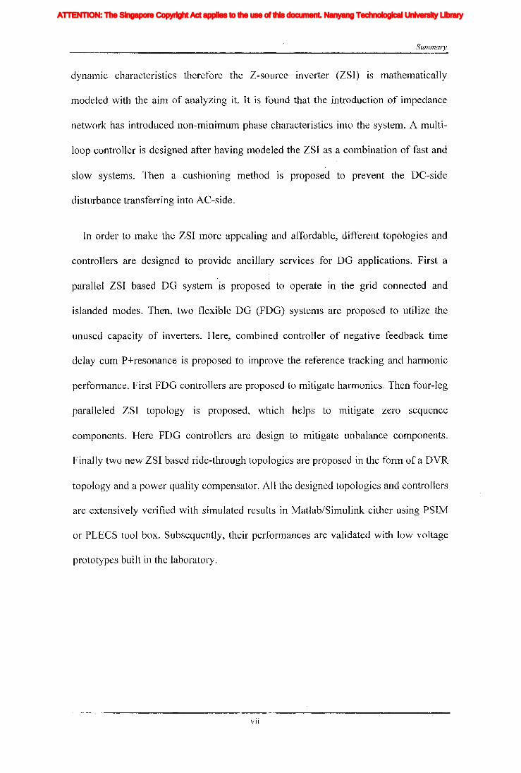
dynamic characteristics therefore the Z-source inverter (ZSI) is mathematically
modeled with the aim of analyzing it. It is found that the introduction of impedance
network has introduced non-minimum phase characteristics into the system. A multi
loop controller is designed after having modeled the ZSI as a combination of fast and
slow systems. Then a cushioning method is proposed to prevent the DC-side
disturbance transferring into AC-side.
In order to make the ZSI more appealing and affordable, different topologies and
controllers are designed to provide ancillary services for DO applications. First a
parallel ZSI based DO system is proposed to operate in the grid connected and
islanded modes. Then, two flexible DO (FDO) systems are proposed to utilize the
unused capacity of inverters. Here, combined controller of negative feedback time
delay cum P+resonance is proposed to improve the reference tracking and harmonic
performance. First FDO controllers are proposed to mitigate harmonics. Then four-leg
paralleled ZSI topology is proposed, which helps to mitigate zero sequence
components. Here FDO controllers are design to mitigate unbalance components.
Finally two new ZSI based ride-through topologies are proposed in the form of a DVR
topology and a power quality compensator. All the designed topologies and controllers
are extensively verified with simulated results in Matlab/Simulink either using PSIM
or PLECS tool box. Subsequently, their performances are validated with low voltage
prototypes built in the laboratory.
VII
Iiq
Iod
Ioq
I odq
I max
1,Ie, Ici,Ic2IDC
IL_m
I MPP
IpvI scITHD
IzI Zn
lap*lap
Ia,Ip,IoIa *, Ip*,10*
Iah,Iphlin
12n
I;
afJ axis currentafJ axis reference currentafJO axis current componentsafJO axis reference current componentsafJ axis harmonic current componentsNeutral current of inverter 1Neutral current of inverter 2Zero sequence reference current
Average Z-source inductor currentPerturbed Z-source inductor current
Perturbed load currentConstantGain factor of fifth harmonics filterGain factor of seventh harmonics filterGain factor of eleventh harmonics filterDC side controller proportional gain of PI controllerDC side controller integral gain of PI controllerGain of the inverterIntegral gain of PI controller in current controllerGain of the hth resonance filterProportional gain of AC side inner loop controllerProportional gain of PI controller in current controllerProportional gain of zero sequence resonance controllerIntegral gain of the resonance controllerIntegral gain of the zero sequence resonance controllerIntegral gain of the hth resonance controllerProportional gain of AC side PI controllerIntegral gain of the AC side PI controllerMultiplying factor for harmonics eliminationDC side filter inductanceLoad inductanceNeutral inductanceGrid inductanceLeakage inductance of transformer
XVII
ATTENTION: The Singapore Copyright Act applies to the use of this document. Nanyang Technological University Library
List
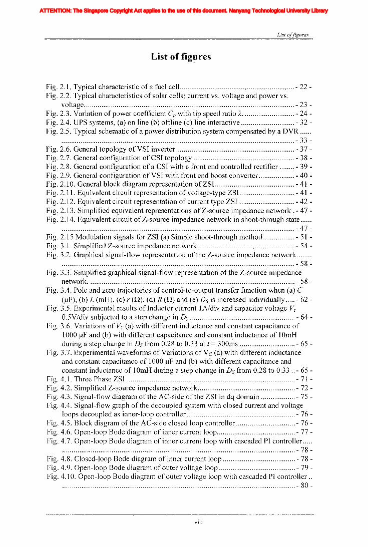
List of figures
Fig. 2.1. Typical characteristic of a fuel celL - 22 -Fig. 2.2. Typical characteristics of solar cells; current vs. voltage and power vs.
voltage - 23 -Fig. 2.3. Variation of power coefficient Cp with tip speed ratio A - 24 -Fig. 2.4. UPS systems, (a) on line (b) offline (c) line interactive - 32 -Fig. 2.5. Typical schematic of a power distribution system compensated by a DVR .
.......................................................................................................................... - 33 -Fig. 2.6. General topology ofVSI inverter - 37 -Fig. 2.7. General configuration of CSI topology - 38 -Fig. 2.8. General configuration of a CSI with a front end controlled rectifier - 39 -Fig. 2.9. General configuration of VSI with front end boost converter - 40 -Fig. 2.10. General block diagram representation of ZSI. - 41 -Fig. 2.11. Equivalent circuit representation of voltage-type ZSI - 41 -Fig. 2.12. Equivalent circuit representation of current type ZSI - 42 -Fig. 2.13. Simplified equivalent representations ofZ-source impedance network. - 47 Fig. 2.14. Equivalent circuit of Z-source impedance network in shoot-through state ......
.......................................................................................................................... - 47-Fig. 2.15 Modulation signals for ZSI (a) Simple shoot-through method - 51 -Fig. 3.1. Simplified Z-source impedance network - 54 -Fig. 3.2. Graphical signal-flow representation of the Z-source impedance network .
.......................................................................................................................... - 58-Fig. 3.3. Simplified graphical signal-flow representation of the Z-source impedance
network - 58 -Fig. 3.4. Pole and zero trajectories of control-to-output transfer function when (a) C
(f.lF), (b) L (mH), (c) r (Q), (d) R (Q) and (e) Ds is increased individually ..... - 62 Fig. 3.5. ExperiInental results of Inductor current IA/div and capacitor voltage Vc
0.5V/div subjected to a step change in Ds - 64 -Fig. 3.6. Variations of Vc(a) with different inductance and constant capacitance of
1000 ~lF and (b) with different capacitance and constan\ inductance of 10mHduring a'step change in Ds from 0.28 to 0.33 at t = 300ms - 65 -
Fig. 3.7. Experimental waveforms of Variations of Vc (a) with different inductanceand constant capacitance of 1000 f.lF and (b) with different capacitance andconstant inductance of 10mH during a step change in Ds from 0.28 to 0.33 .. - 65 -
Fig. 4.1. Three Phase ZSI - 71 -Fig. 4.2. Simplified Z-s,ource impedance network - 72 -Fig. 4.3. Signal-flow diagram of the AC-side of the ZSI in dq domain - 75 -Fig. 4.4. Signal-flow graph of the decoupled system with closed current and voltage
loops decoupled as inner-loop controller - 76 -Fig. 4.5. Block diagram of the AC-side closed loop controller - 76 -Fig. 4.6. Open-loop Bode diagram of inner current loop - 77 -Fig. 4.7. Open-loop Bode diagram of inner current loop with cascaded PI controller .....
.......................................................................................................................... - 78-Fig. 4.8. Closed-loop Bode diagram of inner current loop - 78 -Fig. 4.9. Open-loop Bode diagram of outer voltage loop - 79 -Fig. 4.10. Open-loop Bode diagraln of outer voltage loop with cascaded PI controller ..
.......................................................................................................................... - 80-
Vlll
Iiq
Iod
Ioq
I odq
I max
1,Ie, Ici,Ic2IDC
IL_m
I MPP
IpvI scITHD
IzI Zn
lap*lap
Ia,Ip,IoIa *, Ip*,10*
Iah,Iphlin
12n
I;
afJ axis currentafJ axis reference currentafJO axis current componentsafJO axis reference current componentsafJ axis harmonic current componentsNeutral current of inverter 1Neutral current of inverter 2Zero sequence reference current
Average Z-source inductor currentPerturbed Z-source inductor current
Perturbed load currentConstantGain factor of fifth harmonics filterGain factor of seventh harmonics filterGain factor of eleventh harmonics filterDC side controller proportional gain of PI controllerDC side controller integral gain of PI controllerGain of the inverterIntegral gain of PI controller in current controllerGain of the hth resonance filterProportional gain of AC side inner loop controllerProportional gain of PI controller in current controllerProportional gain of zero sequence resonance controllerIntegral gain of the resonance controllerIntegral gain of the zero sequence resonance controllerIntegral gain of the hth resonance controllerProportional gain of AC side PI controllerIntegral gain of the AC side PI controllerMultiplying factor for harmonics eliminationDC side filter inductanceLoad inductanceNeutral inductanceGrid inductanceLeakage inductance of transformer
XVII
ATTENTION: The Singapore Copyright Act applies to the use of this document. Nanyang Technological University Library

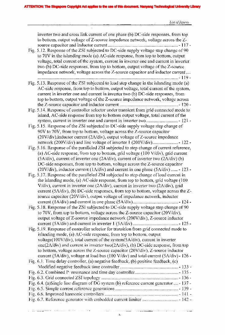
List offigures
Fig. 4.11. Closed-loop Bode diagralTI of the outer voltage loop - 80 -Fig. 4.12. Block diagram representation of Z-source impedance network - 81 -Fig. 4.13. Block diagram representation of Z-source impedance network - 82 -Fig. 4.14. Open-loop Bode diagram ofIL in DC-side - 83 -Fig. 4.15. Block diagram representation of Z-source impedance network with closed
current and voltage loops with PI controller - 83 -Fig. 4.16. Open-loop Bode diagram of IL with filter and P controller in DC-side .. - 84-Fig. 4.17. Closed-loop Bode diagram of inner current loop in DC-side - 84 -Fig. 4.18. Open-loop Bode diagram of outer voltage loop in DC-side - 85 -Fig. 4.19. Open-loop Bode diagram of outer voltage loop with cascaded PI and low
pass filter in DC-side ' - 86 -Fig. 4.20. Closed-loop Bode diagram of outer voltage loop in DC-side - 86 -Fig. 4.21. Closed-loop control system diagram of ZS1. - 87 -Fig. 4.22. State transient diagram - 87 -Fig. 4.23. Simulated results for step change in the input voltage, (a) from top, output
phase voltage across the filter capacitor, load current, and output voltage ofimpedance network, (b) from top, voltage across the capacitor, inductor currentand shoot-through duty ratio in the DC-side - 90 -
Fig. 4.24. Simulated results for step change in the load current, (a) from top, outputphase voltage across the filter capacitor, load current, and output voltage ofimpedance network, (b) from top, voltage across the capacitor, inductor currentand shoot-through duty ratio in the DC-side - 91 -
Fig. 4.25. The response of ZSI output voltage subjected to step change in inputvoltage, voltage across Z-source capacitor (Ve) (20 V/div), output voltage (Vout)
(50V/div) - 93 -Fig. 4.26. Response of Z-source impedance network subjected to input voltage step
change, voltage across Z-source capacitor (Ve) (20 V/div), Z-source inductorcurrent(IL) 3 (A/div) - 93 -
Fig. 4.27. Load current (ILoad) subjected to a load step change (1 A/div) - 94 -Fig. 4.28. Output voltage variation subjected to a load step change (60 V/div) - 94 -Fig. 4.29. Response of Z-source impedance network subjected to a load step change,
voltage across the capacitor (30 V/div) and inductor current (2.5 A/div) - 94-Fig. 5.1. Circuit diagram of grid connected paralleled ZSIs - 100 -Fig. 5.2. Modulation and switching signals - 103 -Fig. 5.3 Simplified diagram of proposed DG system - 104 -Fig. 5.4. Overall control diagram - 106 -Fig. 5.5. AC-side DG system in synchronous reference frame (a) direct axis (b)
qudrature axis (c) zero-sequence - 109 -Fig. 5.6. AC-side current controller (a) direct and quadratic axis controller (b) zero
sequence controller - 110 -Fig. 5.7. Outer voltage loop controller in islanding mode - 112 -Fig. 5.8. Operating mode selector - 113 -Fig. 5.9. DC-side controller - 114 -Fig. 5.10. Response of the ZSI subjected to DC-side supply voltage step change of 90
to 70V (a) DC-side responses, from top to bottom, output voltage of Z-sourceimpedance network, voltage across the Z-source capacitor and inductor current,(b) AC-side response, from top to bottom, grid current, current in inverter one,current in inverter two and cross link current of one phase - 116 -
Fig. 5.11. Response of the ZSI subjected to step change power reference (a) AC-sideresponse, from top to bottom, grid current, current in inverter one, current in
IX
Iiq
Iod
Ioq
I odq
I max
1,Ie, Ici,Ic2IDC
IL_m
I MPP
IpvI scITHD
IzI Zn
lap*lap
Ia,Ip,IoIa *, Ip*,10*
Iah,Iphlin
12n
I;
afJ axis currentafJ axis reference currentafJO axis current componentsafJO axis reference current componentsafJ axis harmonic current componentsNeutral current of inverter 1Neutral current of inverter 2Zero sequence reference current
Average Z-source inductor currentPerturbed Z-source inductor current
Perturbed load currentConstantGain factor of fifth harmonics filterGain factor of seventh harmonics filterGain factor of eleventh harmonics filterDC side controller proportional gain of PI controllerDC side controller integral gain of PI controllerGain of the inverterIntegral gain of PI controller in current controllerGain of the hth resonance filterProportional gain of AC side inner loop controllerProportional gain of PI controller in current controllerProportional gain of zero sequence resonance controllerIntegral gain of the resonance controllerIntegral gain of the zero sequence resonance controllerIntegral gain of the hth resonance controllerProportional gain of AC side PI controllerIntegral gain of the AC side PI controllerMultiplying factor for harmonics eliminationDC side filter inductanceLoad inductanceNeutral inductanceGrid inductanceLeakage inductance of transformer
XVII
ATTENTION: The Singapore Copyright Act applies to the use of this document. Nanyang Technological University Library
List offigures
inverter two and cross link current of one phase (b) DC-side responses, from topto bottom, output voltage of Z-source impedance network, voltage across the Z-source capacitor and inductor current - 117 -
Fig. 5.12. Response of the ZSI subjected to DC-side supply voltage step change of90to 70V in the islanding mode (a) AC-side response, from top to bottom, outputvoltage, total current of the system, current in inverter one and current in invertertwo (b) DC-side responses, from top to bottom, output voltage of the Z-sourceimpedance network, voltage across the Z-source capacitor and inductor current ............................................................................................................................ - 119 -
Fig. 5.13. Response of the ZSI subjected to load step change in the islanding mode (a)AC-side response, from top to bottom, output voltage, total current of the system,current in inverter one and current in inverter two (b) DC-side responses, fromtop to bottom, output voltage of the Z-source impedance network, voltage acrossthe Z-source capacitor and inductor current - 120 -
Fig. 5.14. Response of controller selector under transient from grid connected mode toisland, AC-side response from top to bottom output voltage, total current of thesystem, current in inverter one and current in inverter two - 121 -
Fig. 5.15. Response of the ZSI subjected to DC-side supply voltage step change of90V to 70V, from top to bottom, voltage across the Z-source capacitor(20V/div),inductor current (2A/div), output voltage of Z-source impedancenetwork (200VIdiv) and line voltage of inverter 1 (200YIdiv) - 122 -
Fig. 5.16. Response of the paralleled ZSI subjected to step change of current reference,(a) AC-side response, from top to bottom, grid voltage (100 Y/div), grid current(5A/div), current of inverter one (2A/div), current of inverter two (2A/div) (b)DC-side responses, from top to bottom, voltage across the Z-source capacitor(20V/div), inductor current (IA/div) and current in one phase (5A/div) - 123 -
Fig. 5.17. Response of the paralleled ZSI subjected to step change of load current inthe islanding mode, (a) AC-side response, from top to bottom, grid voltage (100VIdiv), current in inverter one (2A/div), current in inverter two (2A/div), gridcurrent (5A/div), (b) DC-side responses, from top to bottom, voltage across the Zsource capacitor (20Y/div), output voltage of impedance network, inductorcurrent (IA/div) and current in one phase (5A/div) - 124 -
Fig. 5.18. Response of the ZSI subjected to DC-side supply voltage step change of 90to 70V, from top to bottom, voltage across the Z-source capacitor (20YIdiv),output voltage of Z-source impedance network (200Y/div), Z-source inductorcurrent (5A/div) and current in inverter 1 (5A/div) - 125 -
Fig. 5.19. Response of controller selector for transition from grid connected mode toislanding mode, (a) AC-side response, from top to bottom, outputvoltage(l OOVIdiv), total current of the system(5A/div), current in inverterone(2A/div) and current in inverter two(2A/div), (b) DC-side response, from topto bottom, voltage across the Z-source capacitor (20Y/div), Z-source inductorcurrent (5A/div), voltage at load bus (100 Y/div) and total current (5A/div)- 126-
Fig. 6.1. Time delay controller, (a) negative feedback, (b) positive feedback, (c)Modified negative feedback time controller - 133 -
Fig. 6.2. Combined P+resonance and time day controller - 135 -Fig. 6.3. Grid connected ZSI topology - 136 -Fig. 6.4. (a)Single line diagram ofDG system (b) reference current generator - 137 -Fig. 6.5. Simple current reference generations - 139 -Fig. 6.6. Improved harmonic controllers - 141 -Fig. 6.7. Reference generator with embedded current limiter - 142 -
x
Iiq
Iod
Ioq
I odq
I max
1,Ie, Ici,Ic2IDC
IL_m
I MPP
IpvI scITHD
IzI Zn
lap*lap
Ia,Ip,IoIa *, Ip*,10*
Iah,Iphlin
12n
I;
afJ axis currentafJ axis reference currentafJO axis current componentsafJO axis reference current componentsafJ axis harmonic current componentsNeutral current of inverter 1Neutral current of inverter 2Zero sequence reference current
Average Z-source inductor currentPerturbed Z-source inductor current
Perturbed load currentConstantGain factor of fifth harmonics filterGain factor of seventh harmonics filterGain factor of eleventh harmonics filterDC side controller proportional gain of PI controllerDC side controller integral gain of PI controllerGain of the inverterIntegral gain of PI controller in current controllerGain of the hth resonance filterProportional gain of AC side inner loop controllerProportional gain of PI controller in current controllerProportional gain of zero sequence resonance controllerIntegral gain of the resonance controllerIntegral gain of the zero sequence resonance controllerIntegral gain of the hth resonance controllerProportional gain of AC side PI controllerIntegral gain of the AC side PI controllerMultiplying factor for harmonics eliminationDC side filter inductanceLoad inductanceNeutral inductanceGrid inductanceLeakage inductance of transformer
XVII
ATTENTION: The Singapore Copyright Act applies to the use of this document. Nanyang Technological University Library
List offigures .
Fig. 6.8. AC-side controller - 145 -Fig. 6.9. DC-side controller - 146 -Fig. 6.10. Mode transition from 1st mode to 2nd mode with simple harmonic filter at
t=250ms, from top, voltage at PCC, inverter output current, nonlinear loadcurrent and grid current - 147 -
Fig. 6.11. Mode transition from 1st mode to 2nd mode with specific harmonicelimination method at t=250ms, from top, voltage at PCC, inverter output current,nonlinear load current and grid current. - 148 -
Fig. 6.12. Gain factor kl for simple and specific harmonic elimination methods, modetransition from 1st mode to 2nd mode at t=250ms - 148 -
Fig. 6.13. Harmonic spectrum of voltage at PCC - 149-Fig. 6.14. Harmonic spectrum of load current - 150 -Fig. 6.15. Harmonic spectrum of output current of inverter - 150 -Fig. 6.16. Harmonic spectrum of grid current - 150 -Fig. 6.17. DC-side response to source voltage step, from top to bottom, the output
voltage of Z-source impedance network, inductor current and voltage across thecapacitor - 151 -
Fig. 6.18. Reference tracking of the current controller. - 152 -Fig. 6.19. Experimental results for mode transition from 1st mode to 2nd mode, from
top to bottom, inverter output current, voltage across the load, grid current andnonlinear load current respectively - 154 -
Fig. 6.20. Output current of the inverter - 154 -Fig. 6.21. Harmonic spectrums (a) Voltage at the load busses, (b) Output current of
inverter, (c) Grid current and (d) Load current - 155 -Fig. 6.22. DC-side response to a source voltage step increase from top to bottom, input
voltage, inductor current, voltage across the capacitor and output voltage of Z-source impedance network - 156 -
Fig. 6.23. Four-leg parallel ZSIs - 159-Fig. 6.24. Modulation and switching signals - 161 -Fig. 6.25. (a) Single line diagram of a typical distribution system, (b) Case study used
for simulation and experiments with ZSI. - 163 -Fig. 6.26. Reference current generator - 164 -Fig. 6.27. Simplified diagram of DG where Ieq=dlaila+ d1bilb+ d1cilc+ d1ni]n+ d2ai2a+
d2bi2b+ d2ci2c+ d2ni2n - 166 -Fig. 6.28. AC-side DO system in stationary reference frame (a) up axis (b) zero - 168 -Fig. 6.29 AC-side controllers (a) up controller, (b) zero sequence controller - 170 -Fig. 6.30. Designed controller for four-leg parallel ZSI - 171 -Fig. 6.31. Operating mode transition from first to second, (a) AC-side response, from
top to bottom, grid voltage, PCC voltage, output current and neutral current, (b)Grid current sequence components and (c) DC-side response, from top to bottom,output voltage of impedance network, inductor current and capacitor voltage ........................................................................................................................ - 173 -
Fig. 6.32. (a)Steady state response of parallel ZSIs, (b) DC-side response of parallelinverters for DC input voltage step change voltage across the Z-source capacitor(top), inductor current and supply voltage to inverter (bottom) - 176 -
Fig. 6.33. Response of parallel structure for the operating mode transition from first tosecond, (a) Load voltage, (b) output current and neutral current, (c) from top tobottom, inductor current, voltage across the Z-source capacitor, and supplyvoltage to inverter - 177'-
Fig. 7.1. The ZSI based DVR connected to the power system - 184 -
XI
Iiq
Iod
Ioq
I odq
I max
1,Ie, Ici,Ic2IDC
IL_m
I MPP
IpvI scITHD
IzI Zn
lap*lap
Ia,Ip,IoIa *, Ip*,10*
Iah,Iphlin
12n
I;
afJ axis currentafJ axis reference currentafJO axis current componentsafJO axis reference current componentsafJ axis harmonic current componentsNeutral current of inverter 1Neutral current of inverter 2Zero sequence reference current
Average Z-source inductor currentPerturbed Z-source inductor current
Perturbed load currentConstantGain factor of fifth harmonics filterGain factor of seventh harmonics filterGain factor of eleventh harmonics filterDC side controller proportional gain of PI controllerDC side controller integral gain of PI controllerGain of the inverterIntegral gain of PI controller in current controllerGain of the hth resonance filterProportional gain of AC side inner loop controllerProportional gain of PI controller in current controllerProportional gain of zero sequence resonance controllerIntegral gain of the resonance controllerIntegral gain of the zero sequence resonance controllerIntegral gain of the hth resonance controllerProportional gain of AC side PI controllerIntegral gain of the AC side PI controllerMultiplying factor for harmonics eliminationDC side filter inductanceLoad inductanceNeutral inductanceGrid inductanceLeakage inductance of transformer
XVII
ATTENTION: The Singapore Copyright Act applies to the use of this document. Nanyang Technological University Library
List offigures
Fig. 7.2. Phasor Diagram of power distribution system during a sag - 185 -Fig. 7.3. Block diagram representation of the ZSI based DVR system with the multi-
loop feedback controller - 186 -Fig. 7.4. Block diagram representation of AC-side controller - 188 -Fig. 7.5. Hardware prototype configuration of the DVR - 189 -Fig. 7.6. Simulated results of the DVR under 40% sag, a=supply voltage, b=output
voltage of the DVR and c=voltage across the load - 191 -Fig. 7.7. Simulated results of the DVR at recovery from 40% sag, a=supply voltage,
b=output voltage of the DVR and c=voltage across the load - 192 -Fig. 7.8. Simulated results for a step change in the input DC voltage (40% drop),
a=DC input voltage, b= output voltage of the DVR, c=AC supply voltage,d=output voltage across load - 192 -
Fig. 7.9. Experimental results of the DVR subjected to a 40% sag, a=supply voltageand b=voltage across the load - 193 -
Fig. 7.10. Experimental results of the DVR subjected at recovery from 40% sag,a=supply voltage and b=voltage across the load - 193 -
Fig. 7.11. Experimental results for step change in the input DC voltage (40% drop),a=DC input voltage, b=output voltage of DVR, c=AC supply voltage andd=output voltage across load - 194 -
Fig. 7.12. Circuit diagram of proposed ZSI based power quality compensator - 196 -Fig. 7.13. Block diagram representation of the overall controller - 198 -Fig. 7.14. AC-side controller for shunt inverter. - 200 -Fig. 7.15. AC-side controller for series inverter - 201 -Fig. 7.16. Single line diagram of power circuit - 201 -Fig. 7.17. Response of the AC-side of the ZSI of the DG system for a grid fault, from
top to bottom, grid voltage, load voltage, shunt inverter current, load current, gridcurrent and voltage across the series inverter - 203 -
Fig. 7.18. The DC-side response for grid fault, from top to bottom, output voltage ofZ-source impedance network, inductor current and voltage across capacitor- 204 -
Fig. 7.19. Harmonic spectrum of the load current - 204 -Fig. 7.20. Harmonic spectrum of the load bus voltage - 205 -Fig. 7.21. Harmonic spectrum of the shunt inverter current. - 205 -Fig. 7.22. Harmonic spectrum of the grid current. - 205 -Fig. 7.23. DC-side response to a step change of source voltage, from top to bottom,
output voltage of Z-source impedance network, inductor current and voltageacross capacitor - 206 -
Fig. 7.24. AC-side response to a step change of source voltage, from top to bottom,grid voltage, load voltage, shunt inverter current, load current, grid current andvoltage across the series inverter - 207 -
Fig. 7.25 . Response of the AC-side of ZSI for a DG system during a grid fault, fromtop to bottom, grid voltage (VG), load voltage (VI), grid current (IG) and shuntinverter current (11) (a) oscilloscope (one phase only) (b) acquired data for allphases - 209 -
Fig. 7.26. Z-source side response to a grid fault, from top to bottom, grid voltage,voltage across capacitor, inductor current and output voltage of impedancenetwork - 209 -
Fig. 7.27. Harmonics spectrum of the converter current - 211 -Fig. 7.28. Harmonics spectrum of the grid current - 211 -Fig. 7.29. I-Iarmonics spectrum of the load voltage - 211 -Fig. 7.30. Hanllonics spectrum of the load current. - 212 -
Xli
Iiq
Iod
Ioq
I odq
I max
1,Ie, Ici,Ic2IDC
IL_m
I MPP
IpvI scITHD
IzI Zn
lap*lap
Ia,Ip,IoIa *, Ip*,10*
Iah,Iphlin
12n
I;
afJ axis currentafJ axis reference currentafJO axis current componentsafJO axis reference current componentsafJ axis harmonic current componentsNeutral current of inverter 1Neutral current of inverter 2Zero sequence reference current
Average Z-source inductor currentPerturbed Z-source inductor current
Perturbed load currentConstantGain factor of fifth harmonics filterGain factor of seventh harmonics filterGain factor of eleventh harmonics filterDC side controller proportional gain of PI controllerDC side controller integral gain of PI controllerGain of the inverterIntegral gain of PI controller in current controllerGain of the hth resonance filterProportional gain of AC side inner loop controllerProportional gain of PI controller in current controllerProportional gain of zero sequence resonance controllerIntegral gain of the resonance controllerIntegral gain of the zero sequence resonance controllerIntegral gain of the hth resonance controllerProportional gain of AC side PI controllerIntegral gain of the AC side PI controllerMultiplying factor for harmonics eliminationDC side filter inductanceLoad inductanceNeutral inductanceGrid inductanceLeakage inductance of transformer
XVII
ATTENTION: The Singapore Copyright Act applies to the use of this document. Nanyang Technological University Library
List offigures
Fig. 7.31 DC-side response to a step change in source voltage, from top to bottom,voltage across Z-source capacitor, DC input voltage, inductor current - 212 -
XIII
Iiq
Iod
Ioq
I odq
I max
1,Ie, Ici,Ic2IDC
IL_m
I MPP
IpvI scITHD
IzI Zn
lap*lap
Ia,Ip,IoIa *, Ip*,10*
Iah,Iphlin
12n
I;
afJ axis currentafJ axis reference currentafJO axis current componentsafJO axis reference current componentsafJ axis harmonic current componentsNeutral current of inverter 1Neutral current of inverter 2Zero sequence reference current
Average Z-source inductor currentPerturbed Z-source inductor current
Perturbed load currentConstantGain factor of fifth harmonics filterGain factor of seventh harmonics filterGain factor of eleventh harmonics filterDC side controller proportional gain of PI controllerDC side controller integral gain of PI controllerGain of the inverterIntegral gain of PI controller in current controllerGain of the hth resonance filterProportional gain of AC side inner loop controllerProportional gain of PI controller in current controllerProportional gain of zero sequence resonance controllerIntegral gain of the resonance controllerIntegral gain of the zero sequence resonance controllerIntegral gain of the hth resonance controllerProportional gain of AC side PI controllerIntegral gain of the AC side PI controllerMultiplying factor for harmonics eliminationDC side filter inductanceLoad inductanceNeutral inductanceGrid inductanceLeakage inductance of transformer
XVII
ATTENTION: The Singapore Copyright Act applies to the use of this document. Nanyang Technological University Library

List oftables
List of tables
Table 3-1: System parameters used for simulating the ZSI - 63 -Table 4-1: Parameters for simulation of closed-loop system - 92 -Table 4-2: Parameters for the experimental set-up - 95 -Table 5-1 - 125 -Table 6-1: Selected parameters - 156 -Table 6-2: parameters selected for the prototype - 178 -Table 7-1 - 191 -Table 7-2 - 212 -
XIV
Iiq
Iod
Ioq
I odq
I max
1,Ie, Ici,Ic2IDC
IL_m
I MPP
IpvI scITHD
IzI Zn
lap*lap
Ia,Ip,IoIa *, Ip*,10*
Iah,Iphlin
12n
I;
afJ axis currentafJ axis reference currentafJO axis current componentsafJO axis reference current componentsafJ axis harmonic current componentsNeutral current of inverter 1Neutral current of inverter 2Zero sequence reference current
Average Z-source inductor currentPerturbed Z-source inductor current
Perturbed load currentConstantGain factor of fifth harmonics filterGain factor of seventh harmonics filterGain factor of eleventh harmonics filterDC side controller proportional gain of PI controllerDC side controller integral gain of PI controllerGain of the inverterIntegral gain of PI controller in current controllerGain of the hth resonance filterProportional gain of AC side inner loop controllerProportional gain of PI controller in current controllerProportional gain of zero sequence resonance controllerIntegral gain of the resonance controllerIntegral gain of the zero sequence resonance controllerIntegral gain of the hth resonance controllerProportional gain of AC side PI controllerIntegral gain of the AC side PI controllerMultiplying factor for harmonics eliminationDC side filter inductanceLoad inductanceNeutral inductanceGrid inductanceLeakage inductance of transformer
XVII
ATTENTION: The Singapore Copyright Act applies to the use of this document. Nanyang Technological University Library

APFASDCSIDCMDGDSPDVRESREPLDFACTSGTOIECIGBTKVLKCLNEMAMOSFETPCCPEMFCPLL
1 PLECSPSIMPWMRHHPSOFeSPFCSTATCOMSVCTHDUPFCUPQCUPSVSDVSIZSI
Abbreviations
Active power filterAdjustable speed drivesCurrent source inverterDiscontinuous conduction modeDistributed generationDigital signal processorDynamic voltage restorerEquivalent series resistanceElectronically programmable logic deviceFlexible ac transmission systemGate turn-off transistorInternational Electrotechnical commissionInsulated gate bipolar transistorKirchhoff voltage lowKirchhoff current lowNational Electrical Manufacturers Association of USAMetal oxide semiconductor field effect transistorPoint of common couplingProton exchange n1embrane fuel cellPhase lock looptrade mark of power electronic simulating softwaretrade mark of power electronic simulating softwarePulse width modulationRight hand half planeSolid Oxide Fuel CellSolid polymer fuel cellStatic compensatorStatic var compensatorTotal harmonic distortionUnified power flow controllerUnified power quality compensatorUninterruptible power supplyVariable speed driveVoltage source inverterZ-source inverter
xv
Abbreviations
Iiq
Iod
Ioq
I odq
I max
1,Ie, Ici,Ic2IDC
IL_m
I MPP
IpvI scITHD
IzI Zn
lap*lap
Ia,Ip,IoIa *, Ip*,10*
Iah,Iphlin
12n
I;
afJ axis currentafJ axis reference currentafJO axis current componentsafJO axis reference current componentsafJ axis harmonic current componentsNeutral current of inverter 1Neutral current of inverter 2Zero sequence reference current
Average Z-source inductor currentPerturbed Z-source inductor current
Perturbed load currentConstantGain factor of fifth harmonics filterGain factor of seventh harmonics filterGain factor of eleventh harmonics filterDC side controller proportional gain of PI controllerDC side controller integral gain of PI controllerGain of the inverterIntegral gain of PI controller in current controllerGain of the hth resonance filterProportional gain of AC side inner loop controllerProportional gain of PI controller in current controllerProportional gain of zero sequence resonance controllerIntegral gain of the resonance controllerIntegral gain of the zero sequence resonance controllerIntegral gain of the hth resonance controllerProportional gain of AC side PI controllerIntegral gain of the AC side PI controllerMultiplying factor for harmonics eliminationDC side filter inductanceLoad inductanceNeutral inductanceGrid inductanceLeakage inductance of transformer
XVII
ATTENTION: The Singapore Copyright Act applies to the use of this document. Nanyang Technological University Library

C, C j , C2
CpCf, CFdd
ddq
dnl
dn2
dq
dx , da, db, dedia, dib, diedia, di~, diod2a, d2b, d2e
DA
Ds
15A
15s
Ds
ff
fGi, G2, G3, G4, G5
h
ign
igx, iga " igb igeiga, ig~, igofix, fia, fib, fiefIx, fta, itb, heiLfOl
f02fin
fix, fia, fib, fie
i2n
f2x, f2a, f2b' i2e
fa, ffJial' i~l, f~o
1lc;fm
leq
lid
l;dq
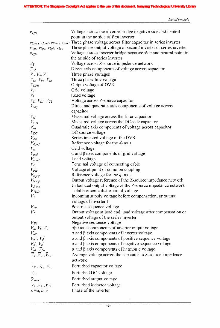
List ofsymbols
List of symbols
DC side filter capacitanceTu~bine power coefficientFilter capacitanceDirect axis components of modulation indexDirect and quadratic axis components of tTIodulation indexAverage switching duty ratio of neutral leg of inverter 1Average switching duty ratio of neutral leg of inverter 2Quadratic axis components of modulation indexAverage switching duty ratio of each phaseInverter 1 average switching duty ratio of each phaseafJO axis modulation ratios of the first inverterInverter 2 average switching duty ratio of each phaseNon-shoot through duty ratioShoot through duty ratioAverage active duty ratio
Average shoot-through duty ratio
Perturbed active duty ratio
Perturbed shoot-through duty ratioVoltage or current
Average quantity
Perturbed quantity
GainsHarmonic numberCirculating current or capacitor currentDirect and quadrature axis components of inverter outputcurrentGrid neutral currentThree phase grid currentsafJO axis grid currentThree phase inverter currentsThree phase load currentsLoad currentZero sequence current of inverter 1Zero sequence current of inverter 2Neutral current of inverter 1Three phase output current of the first inverter or shunt inverterNeutral current of inverter 2Three phase output current of second inverter or series invertera and fJ axis components of inverter output currentaf30 axis first inverter output currentCurrentMeasured filter capacitor currentEquivalent currentDirect axis components of converter currentDirect and quadratic axis components of converter current
XVI
Iiq
Iod
Ioq
I odq
I max
1,Ie, Ici,Ic2IDC
IL_m
I MPP
IpvI scITHD
IzI Zn
lap*lap
Ia,Ip,IoIa *, Ip*,10*
Iah,Iphlin
12n
I;
afJ axis currentafJ axis reference currentafJO axis current componentsafJO axis reference current componentsafJ axis harmonic current componentsNeutral current of inverter 1Neutral current of inverter 2Zero sequence reference current
Average Z-source inductor currentPerturbed Z-source inductor current
Perturbed load currentConstantGain factor of fifth harmonics filterGain factor of seventh harmonics filterGain factor of eleventh harmonics filterDC side controller proportional gain of PI controllerDC side controller integral gain of PI controllerGain of the inverterIntegral gain of PI controller in current controllerGain of the hth resonance filterProportional gain of AC side inner loop controllerProportional gain of PI controller in current controllerProportional gain of zero sequence resonance controllerIntegral gain of the resonance controllerIntegral gain of the zero sequence resonance controllerIntegral gain of the hth resonance controllerProportional gain of AC side PI controllerIntegral gain of the AC side PI controllerMultiplying factor for harmonics eliminationDC side filter inductanceLoad inductanceNeutral inductanceGrid inductanceLeakage inductance of transformer
XVII
ATTENTION: The Singapore Copyright Act applies to the use of this document. Nanyang Technological University Library

Iiq
Iod
Ioq
I odq
I max
1,Ie, Ici,Ic2IDC
IL_m
I MPP
IpvI scITHD
IzI Zn
lap*lap
Ia,Ip,IoIa *, Ip*,10*
Iah,Iphlin
12n
I;IL,ILl ILl
IL ,ILl' IL2
1Load
kksk7
klJ
Kcp
Kei
K1cK i
K1hKip
Kp
KpoKr
KyoKrhKvp
KVi
K j
L, L j , L2
LILn
Lg
L t
List ofsymbols
Quadratic axis components of converter currentDirect axis components of output currentQuadratic axis components of output currentDirect and quadratic axis components of output currentMaximum currentLine current, Load currentCurrent across Z-source capacitorEquivalent DC source currentMeasured current in the DC-side inductorOutput current at maximum power pointOutput current of PV panelShort-circuit current of PV panelTotal harmonic distortion in currentCirculation currentCirculation current in the 4th legafJ axis currentafJ axis reference currentafJO axis current componentsafJO axis reference current componentsafJ axis harmonic current componentsNeutral current of inverter 1Neutral current of inverter 2Zero sequence reference current
Average Z-source inductor currentPerturbed Z-source inductor current
Perturbed load currentConstantGain factor of fifth harmonics filterGain factor of seventh harmonics filterGain factor of eleventh harmonics filterDC side controller proportional gain of PI controllerDC side controller integral gain of PI controllerGain of the inverterIntegral gain of PI controller in current controllerGain of the hth resonance filterProportional gain of AC side inner loop controllerProportional gain of PI controller in current controllerProportional gain of zero sequence resonance controllerIntegral gain of the resonance controllerIntegral gain of the zero sequence resonance controllerIntegral gain of the hth resonance controllerProportional gain of AC side PI controllerIntegral gain of the AC side PI controllerMultiplying factor for harmonics eliminationDC side filter inductanceLoad inductanceNeutral inductanceGrid inductanceLeakage inductance of transformer
XVII
Iiq
Iod
Ioq
I odq
I max
1,Ie, Ici,Ic2IDC
IL_m
I MPP
IpvI scITHD
IzI Zn
lap*lap
Ia,Ip,IoIa *, Ip*,10*
Iah,Iphlin
12n
I;
afJ axis currentafJ axis reference currentafJO axis current componentsafJO axis reference current componentsafJ axis harmonic current componentsNeutral current of inverter 1Neutral current of inverter 2Zero sequence reference current
Average Z-source inductor currentPerturbed Z-source inductor current
Perturbed load currentConstantGain factor of fifth harmonics filterGain factor of seventh harmonics filterGain factor of eleventh harmonics filterDC side controller proportional gain of PI controllerDC side controller integral gain of PI controllerGain of the inverterIntegral gain of PI controller in current controllerGain of the hth resonance filterProportional gain of AC side inner loop controllerProportional gain of PI controller in current controllerProportional gain of zero sequence resonance controllerIntegral gain of the resonance controllerIntegral gain of the zero sequence resonance controllerIntegral gain of the hth resonance controllerProportional gain of AC side PI controllerIntegral gain of the AC side PI controllerMultiplying factor for harmonics eliminationDC side filter inductanceLoad inductanceNeutral inductanceGrid inductanceLeakage inductance of transformer
XVII
ATTENTION: The Singapore Copyright Act applies to the use of this document. Nanyang Technological University Library
LA,LB
LF, LfMp=d/dtp*
PPA,PB
PMPP
PPV
QQ*r, rJ, r2
rfrg
r/
rn
rtR, RJ, R2RrSeqSi where i=1 to 6Slj where j=1 to 6S2j where j=l to 6TTHD]THDv
Ti where i=1 to 6ToT]UMPP
UocUpvV
Vd
Vdg, Vqg
Vdm, vqm
Vgx, Vga, Vgb, vge
Vgxm, Vgam, Vgbm, Vgem
Vgm
Vga , Vg~, VgO
VL, VL], VL2
Vpx
Vxm, Vam, Vbm, Vem
Vxg, Vag, Vbg, Veg
Vga, VgfJ
Vanb VmfJ
V]xm, Vl anh Vlbm, Vl em
Vlgx, Vl ga , Vlgb, Vlge
List ofsymbols
Loop transmittances of signal flow graphFilter inductanceModulation indexDerivativeActive power referenceActive powerPath transmittancesPower at maximum power pointOutput voltage at PV panelReactive powerReactive power referenceParasitic resistances of inductors Z-source inductorParasitic resistance of filter inductorParasitic resistance grid side inductorLoad resistanceParasitic resistance of neutral inductanceResistance of transformerEquivalent series resistance (ESR) of Z-source capacitorTurbine radiusSwitch at equivalent modelInverter switchesInverter 1 switchesInverter 2 switchesPeriod of the carrier signalTotal harmonic distortion in currentTotal harmonic distortion in voltageThyristor switchesTotal shoot-through timeNon- shoot-through timeVoltage at maximum power pointOpen circuit voltageOutput voltage of PV panelWind speedVoltage at the input side of Z-source impedance networkDirect and quadrature axis components of grid voltageDirect and quadrature axis components of inverter outputvoltageThree phase inverter output voltageThree phase output voltage at the filter bankVoltage between first inverter bridge negative and neutral pointin the ac sideafJO axis grid voltageVoltage ~across Z-source inductorTerminal voltage of connecting cable,Three phase voltage across filter capacitor in inverterGrid voltagea and fJ axis components of the grid voltagea and fJ axis components of inverter output voltageThe local load voltage of UPQCOutput voltage of inverter 1
XYlli
Iiq
Iod
Ioq
I odq
I max
1,Ie, Ici,Ic2IDC
IL_m
I MPP
IpvI scITHD
IzI Zn
lap*lap
Ia,Ip,IoIa *, Ip*,10*
Iah,Iphlin
12n
I;
afJ axis currentafJ axis reference currentafJO axis current componentsafJO axis reference current componentsafJ axis harmonic current componentsNeutral current of inverter 1Neutral current of inverter 2Zero sequence reference current
Average Z-source inductor currentPerturbed Z-source inductor current
Perturbed load currentConstantGain factor of fifth harmonics filterGain factor of seventh harmonics filterGain factor of eleventh harmonics filterDC side controller proportional gain of PI controllerDC side controller integral gain of PI controllerGain of the inverterIntegral gain of PI controller in current controllerGain of the hth resonance filterProportional gain of AC side inner loop controllerProportional gain of PI controller in current controllerProportional gain of zero sequence resonance controllerIntegral gain of the resonance controllerIntegral gain of the zero sequence resonance controllerIntegral gain of the hth resonance controllerProportional gain of AC side PI controllerIntegral gain of the AC side PI controllerMultiplying factor for harmonics eliminationDC side filter inductanceLoad inductanceNeutral inductanceGrid inductanceLeakage inductance of transformer
XVII
ATTENTION: The Singapore Copyright Act applies to the use of this document. Nanyang Technological University Library
List ofsymbols
V sum
Vlgm
vC, VCl, VC2
V2N
Va, VfJ' Va
Vap
Va+, Vp+
V a-, Vp-
Vah, VPh
~ ~ ~
VL,VLI,VU
X =a, b, C
Vcl
Vc m
Vcq
VDC
Vdvr
Vd_rel
Vg
VgafJ
VLoad
Vp
Vpcc
Vq_rel
VS_rel
VS_cal
VTHD
Vl
VsVcd
Va, Vb, V c
Vab, Vbc, V ca
VDVR
Vg
VIVc, VCl, VC2
Vcdq
Voltage across the inverter bridge negative side and neutralpoint in the ac side of first inverter
V2xm', V2am', V2bm', V2cm' Three phase voltage across filter capacitor in series inverterV2gx, V2ga, V2gb, V2gc Three phase output voltage of second inverter or series inverterV2gm' Voltage across inverter bridge negative side and neutral point in
the ac side of series inverterVoltage across Z-source impedance networkDirect axis components ofvoltage across capacitorThree phase voltagesThree phase line voltageOutput voltage ofDVRGrid voltageLoad voltageVoltage across Z-source capacitorDirect and quadratic axis components of voltage acrosscapacitorMeasured voltage across the filter capacitorMeasured voltage across the DC-side capacitorQuadratic axis components of voltage across capacitorDC source voltageSeries injected voltage of the DVRReference voltage for the d- axisGrid voltagea and paxis components of grid voltageLoad voltageTerminal voltage of connecting cableVoltage at point of common couplingReference voltage for the q- axisOutput voltage reference of the Z-source impedance networkCalculated output voltage of the Z-source impedance networkTotal harmonic distortion of voltageIncoming supply voltage before compensation, or outputvoltage of inverter 1Positive sequence voltageOutput voltage at load end, load voltage after compensation oroutput voltage of the series inverterNegative sequence voltageapO axis components of inverter output voltagea and paxis components of inverter voltagea and paxis components of positive sequence voltagea and paxis components of negative sequence voltagea and paxis cOlnponents of harmonic voltageAverage voltage across the capacitor in Z-source impedancenetworkPerturbed capacitor voltage
Perturbed DC voltage
Perturbed output voltagePerturbed inductor voltagePhase of the inverter
XIX
Iiq
Iod
Ioq
I odq
I max
1,Ie, Ici,Ic2IDC
IL_m
I MPP
IpvI scITHD
IzI Zn
lap*lap
Ia,Ip,IoIa *, Ip*,10*
Iah,Iphlin
12n
I;
afJ axis currentafJ axis reference currentafJO axis current componentsafJO axis reference current componentsafJ axis harmonic current componentsNeutral current of inverter 1Neutral current of inverter 2Zero sequence reference current
Average Z-source inductor currentPerturbed Z-source inductor current
Perturbed load currentConstantGain factor of fifth harmonics filterGain factor of seventh harmonics filterGain factor of eleventh harmonics filterDC side controller proportional gain of PI controllerDC side controller integral gain of PI controllerGain of the inverterIntegral gain of PI controller in current controllerGain of the hth resonance filterProportional gain of AC side inner loop controllerProportional gain of PI controller in current controllerProportional gain of zero sequence resonance controllerIntegral gain of the resonance controllerIntegral gain of the zero sequence resonance controllerIntegral gain of the hth resonance controllerProportional gain of AC side PI controllerIntegral gain of the AC side PI controllerMultiplying factor for harmonics eliminationDC side filter inductanceLoad inductanceNeutral inductanceGrid inductanceLeakage inductance of transformer
XVII
ATTENTION: The Singapore Copyright Act applies to the use of this document. Nanyang Technological University Library

aaL1A,~B
~
gApr
Wo
Wh
WeS
W e7
Well
Ws
W7
(011
Load voltage advance· angleOptimum parameter for Naslin polynomialCofactorsGraph determinantSupply voltage phase angleTip speed ratioAir densityTime constant of low pass filterLoad power factor angleSystem frequencyHarmonic angular frequencyCut off frequency of fifth harmonic filterCut off frequency of seventh harmonic filterCut off frequency of eleventh harmonic filterFifth harmonic angular frequencySeventh harmonic angular frequencyEleventh harmonic angular frequency
xx
List
Iiq
Iod
Ioq
I odq
I max
1,Ie, Ici,Ic2IDC
IL_m
I MPP
IpvI scITHD
IzI Zn
lap*lap
Ia,Ip,IoIa *, Ip*,10*
Iah,Iphlin
12n
I;
afJ axis currentafJ axis reference currentafJO axis current componentsafJO axis reference current componentsafJ axis harmonic current componentsNeutral current of inverter 1Neutral current of inverter 2Zero sequence reference current
Average Z-source inductor currentPerturbed Z-source inductor current
Perturbed load currentConstantGain factor of fifth harmonics filterGain factor of seventh harmonics filterGain factor of eleventh harmonics filterDC side controller proportional gain of PI controllerDC side controller integral gain of PI controllerGain of the inverterIntegral gain of PI controller in current controllerGain of the hth resonance filterProportional gain of AC side inner loop controllerProportional gain of PI controller in current controllerProportional gain of zero sequence resonance controllerIntegral gain of the resonance controllerIntegral gain of the zero sequence resonance controllerIntegral gain of the hth resonance controllerProportional gain of AC side PI controllerIntegral gain of the AC side PI controllerMultiplying factor for harmonics eliminationDC side filter inductanceLoad inductanceNeutral inductanceGrid inductanceLeakage inductance of transformer
XVII
ATTENTION: The Singapore Copyright Act applies to the use of this document. Nanyang Technological University Library
Chapter 1
1.1 Motivation
Chapter 1
Introduction
introduction
With the increased energy demand and many inherent advantages, distributed
generation (DG) has to play an influential role in tomorrow's power system operation.
Over the past decades, vast amount of research work has been done in the area of DO
and the needed technology has been developed. Mainly, research works are focused on
developing new sources, advanced converters, and designing controllers to improve
the power quality, reliability and thereby maintaining the correct operation of power
system [1-6]. However, there are still many areas where research needs to be done, in
order to improve the functionality of the DG systems. Research on DG systelTIS is
open in the areas such as new energy sources and their control, interface with the grid
and loads, power quality issues related to grid interacting, improving the reliability and
protection etc.
The present trend is to use renewable DG sources like solar cells, wind turbines and
alternative energy sources like fuel cells in power generation. Such energy sources can
be integrated into the utility grid or consumed isolated from the grid. Also sources like
fuel-cells and solar cells have the highest potential to be the tomorrow's power source.
They are modular, efficient and environmentally friendly. Both of them produce power
in the form of DC voltage that demands power conversion in interfacing to the loads.
However, production and installation cost of fuel-cells is higher but it is decreasing
over the years. To bring the costs to affordable levels, further research work on
improving the energy and power conversion technologies are necessary. Many
- 1 -
Iiq
Iod
Ioq
I odq
I max
1,Ie, Ici,Ic2IDC
IL_m
I MPP
IpvI scITHD
IzI Zn
lap*lap
Ia,Ip,IoIa *, Ip*,10*
Iah,Iphlin
12n
I;
afJ axis currentafJ axis reference currentafJO axis current componentsafJO axis reference current componentsafJ axis harmonic current componentsNeutral current of inverter 1Neutral current of inverter 2Zero sequence reference current
Average Z-source inductor currentPerturbed Z-source inductor current
Perturbed load currentConstantGain factor of fifth harmonics filterGain factor of seventh harmonics filterGain factor of eleventh harmonics filterDC side controller proportional gain of PI controllerDC side controller integral gain of PI controllerGain of the inverterIntegral gain of PI controller in current controllerGain of the hth resonance filterProportional gain of AC side inner loop controllerProportional gain of PI controller in current controllerProportional gain of zero sequence resonance controllerIntegral gain of the resonance controllerIntegral gain of the zero sequence resonance controllerIntegral gain of the hth resonance controllerProportional gain of AC side PI controllerIntegral gain of the AC side PI controllerMultiplying factor for harmonics eliminationDC side filter inductanceLoad inductanceNeutral inductanceGrid inductanceLeakage inductance of transformer
XVII
ATTENTION: The Singapore Copyright Act applies to the use of this document. Nanyang Technological University Library

Chapter 1 Introduction
researches have studied chemical reactions, dynamics of the fuel-cell and have come
up with models to describe the dynamic characteristics [7]. This has enabled the
proper analysis, designing of converters and controllers for fuel-cell systems. It has
been found that the fuel-cell doesn't produce a constant output voltage in dynamic
conditions. The resultant characteristic hinders the possibility of direct connection of
fuel-cell using a single power converter topology and the alternative two-stage
topology would reduce the efficiency. Despite that, fuel-cell systems have been
designed for domestic and grid connected applications [8, 9]. Similarly, solar cells also
have wider operating range due to energy availability etc. The installation cost is very
high, yet solar cells have been used in rural electrification and also interfaced to the
grid. In contrast, wind turbines have gained popularity as technology and it has
improved to a great extent [2, 10, 11]. Different wind turbine topologies have been
developed and are used in operation [12]. The main problem of wind energy is that its
dependency on the availability of wind and fluctuations in wind speed. This would
complicate the operation and control of turbine and generator. Mainly, change in wind
speed would result in change in turbine speed or generated voltage. Resultant voltage
may not have the correct magnitude or frequency demanded by the customer
equipment or the utility. To overcome some of the problems numerous generator
topologies and controlling techniques have been developed. However, each has its
own merits and demerits. Therefore, many unexploded areas are still left for research.
Having identified the fact that certain renewable sources have wide operating
ranges, conventional power converters like voltage source inverter (VSI) and current
source inverter (CSI) with limited operating ranges may become incapable in
converting power into standard grid voltage and frequency. Usually, this lilnitation is
overCOlne by connecting a DC-DC converter at front end of the VSI or CSI [7, 8J.
- 2 -
Iiq
Iod
Ioq
I odq
I max
1,Ie, Ici,Ic2IDC
IL_m
I MPP
IpvI scITHD
IzI Zn
lap*lap
Ia,Ip,IoIa *, Ip*,10*
Iah,Iphlin
12n
I;
afJ axis currentafJ axis reference currentafJO axis current componentsafJO axis reference current componentsafJ axis harmonic current componentsNeutral current of inverter 1Neutral current of inverter 2Zero sequence reference current
Average Z-source inductor currentPerturbed Z-source inductor current
Perturbed load currentConstantGain factor of fifth harmonics filterGain factor of seventh harmonics filterGain factor of eleventh harmonics filterDC side controller proportional gain of PI controllerDC side controller integral gain of PI controllerGain of the inverterIntegral gain of PI controller in current controllerGain of the hth resonance filterProportional gain of AC side inner loop controllerProportional gain of PI controller in current controllerProportional gain of zero sequence resonance controllerIntegral gain of the resonance controllerIntegral gain of the zero sequence resonance controllerIntegral gain of the hth resonance controllerProportional gain of AC side PI controllerIntegral gain of the AC side PI controllerMultiplying factor for harmonics eliminationDC side filter inductanceLoad inductanceNeutral inductanceGrid inductanceLeakage inductance of transformer
XVII
ATTENTION: The Singapore Copyright Act applies to the use of this document. Nanyang Technological University Library
Chapter 1 Introduction
Also if the energy source is AC, then AC-DC converter or simple diode rectifier
followed by DC-DC converter is employed [10, 13]. However, these hybrid topologies
are known to be inefficient and the controlling would be difficult. Therefore, a single
stage converter would be most appropriate. Recently proposed Z-source inverter (lSI)
is such single stage topology which would overcome the aforementioned limitations
[14]. The ZSI consists of "X" shaped impedance network formed by two capacitors
and two inductors and it provides a unique buck-boost characteristics. Moreover,
unlike VSI, the need of dead time would not arise with this topology. Due to these
attractive features, it has found applications in numerous industrial applications
including variable speed drives and DO [15-18]. However, it has not been widely
researched as a DO t~pology. Moreover, all these industrial applications require proper
closed loop controlling to adjust its operating conditions subjected to changes in both
input and output conditions. On the other hand the presence of "X" shaped impedance
network and the need of short circuiting of inverter arm to boost the voltage would
cOlnplicate the controlling of ZSI. This would require research effort on analyzing the
dynamics of ZSI.
Future DO system would not be limited to conventional active and reactive power
generation. Mainly due to increased demand for other functions in power system in
order to maintain required level of supply quality and also to reduce the operational
cost and thereby optimize the resources in a DO system. Furthermore, operations of
some of the renewable energy sources are highly dependent on other factors like
source and demand characteristics. For example, solar energy is available only in the
day time and it highly depends on the environmental conditions. Wind energy may
fluctuate all the time. Also, economic and demand side constrains, with
implementation of deregulated power systems and prices discrimination strategies,
- 3 -
Iiq
Iod
Ioq
I odq
I max
1,Ie, Ici,Ic2IDC
IL_m
I MPP
IpvI scITHD
IzI Zn
lap*lap
Ia,Ip,IoIa *, Ip*,10*
Iah,Iphlin
12n
I;
afJ axis currentafJ axis reference currentafJO axis current componentsafJO axis reference current componentsafJ axis harmonic current componentsNeutral current of inverter 1Neutral current of inverter 2Zero sequence reference current
Average Z-source inductor currentPerturbed Z-source inductor current
Perturbed load currentConstantGain factor of fifth harmonics filterGain factor of seventh harmonics filterGain factor of eleventh harmonics filterDC side controller proportional gain of PI controllerDC side controller integral gain of PI controllerGain of the inverterIntegral gain of PI controller in current controllerGain of the hth resonance filterProportional gain of AC side inner loop controllerProportional gain of PI controller in current controllerProportional gain of zero sequence resonance controllerIntegral gain of the resonance controllerIntegral gain of the zero sequence resonance controllerIntegral gain of the hth resonance controllerProportional gain of AC side PI controllerIntegral gain of the AC side PI controllerMultiplying factor for harmonics eliminationDC side filter inductanceLoad inductanceNeutral inductanceGrid inductanceLeakage inductance of transformer
XVII
ATTENTION: The Singapore Copyright Act applies to the use of this document. Nanyang Technological University Library

Chapter 1 Introduction
sOlnetimes it is not economical to deliver active power to grid all the time. Therefore,
interfacing inverters may not use their full capacity all the time. With the increased
penetration of DG inverters, such unutilized resources would be abundant. That could
facilitate some other ancillary functions of power generation, like harmonic mitigation,
unbalance mitigation, zero sequence mitigation etc. Use of DG inverters for ancillary
functions is gaining attention and it is commonly termed as flexible generation [19
21]. Therefore, incorporating such ancillary service could help to gain the attraction to
DO systems and ZSI as a topology.
Also the DG systems have gained the attention due to on-site generation and many
industrial processes adopt this to improve the reliability and the power quality that are
needed in powering high sensitive systems. Commonly such reliability is achieved by
having expensive uninterruptable power supplies (UPS) or auxiliary power supply
systems. Moreover, parallel connected sources are also commonly used to increase the
reliability. This technique has been widely applied with DC-DC converters and DC
AC inverter systems. Such techniques could also be studied for inverter based DG
system to enhance the reliability while catering increased capacity. Alternatively, on
site DG system could be operated in both grid connected and islanding modes
increasing the reliability of supply. However, with the increased penetration of DO
systems in distribution network, stability and reliability could compromise as there is a
possibility of disconnecting these sources during fault conditions. Therefore, in many
countries new grid codes are imposed on the DG systems which delnand the energy
squrces to be kept connected to the grid during fault conditions. These impose new
control challenges on designing controllers for DG systems. Hence, improving the
ride-through of grid faults is also illlportant consideration in order to protect the loads
and DG systems. These aspects present numerous problems that need careful
- 4 -
Iiq
Iod
Ioq
I odq
I max
1,Ie, Ici,Ic2IDC
IL_m
I MPP
IpvI scITHD
IzI Zn
lap*lap
Ia,Ip,IoIa *, Ip*,10*
Iah,Iphlin
12n
I;
afJ axis currentafJ axis reference currentafJO axis current componentsafJO axis reference current componentsafJ axis harmonic current componentsNeutral current of inverter 1Neutral current of inverter 2Zero sequence reference current
Average Z-source inductor currentPerturbed Z-source inductor current
Perturbed load currentConstantGain factor of fifth harmonics filterGain factor of seventh harmonics filterGain factor of eleventh harmonics filterDC side controller proportional gain of PI controllerDC side controller integral gain of PI controllerGain of the inverterIntegral gain of PI controller in current controllerGain of the hth resonance filterProportional gain of AC side inner loop controllerProportional gain of PI controller in current controllerProportional gain of zero sequence resonance controllerIntegral gain of the resonance controllerIntegral gain of the zero sequence resonance controllerIntegral gain of the hth resonance controllerProportional gain of AC side PI controllerIntegral gain of the AC side PI controllerMultiplying factor for harmonics eliminationDC side filter inductanceLoad inductanceNeutral inductanceGrid inductanceLeakage inductance of transformer
XVII
ATTENTION: The Singapore Copyright Act applies to the use of this document. Nanyang Technological University Library

Chapter 1 Introduction
consideration when carryIng out research work In the area of development of
topologies and control strategies of ZSI.
1.2 Objectives
In researching on the ZSI it has been found that a very little emphasis is given on
understanding the dynamics of ZSI and its impedance network. Therefore, the main
objective of this thesis is to analyze and develop a mathematical model for the recently
proposed ZSI and to develop controllers to achieve different control objectives. Then
different ZSI based topologies are studied for improving power quality and reliability
of power generation particularly in distribution level and this would enable ZSI to gain
popularity as a DG topology.
Mathematical modeling of ZSI and development of multi loop controller for DG
systems
ZSI is a recently proposed inverter topology having inherent capability to buck or
boost its output voltage. It has X shaped impedance network connected in front end of
the inverter bridge, making the system complicated and non-linear. It is a
multivariable system with two input variables, namely modulation index and shoot
through, which is different frOITI traditional VSI or CSI. Moreover, modulation index
and shoot-through are interdependent making the system even more complicated.
Therefore, different values for modulation index and shoot-through can be selected to
achieve particular a voltage gain. Obtaining a mathematical model is essential in order
to develop controllers that would select suitable modulation index and shoot-through.
Then, obtained model could be used to design controllers that would maintain quality
output by rejecting disturbances from both energy source and the grid.
- 5 -
Iiq
Iod
Ioq
I odq
I max
1,Ie, Ici,Ic2IDC
IL_m
I MPP
IpvI scITHD
IzI Zn
lap*lap
Ia,Ip,IoIa *, Ip*,10*
Iah,Iphlin
12n
I;
afJ axis currentafJ axis reference currentafJO axis current componentsafJO axis reference current componentsafJ axis harmonic current componentsNeutral current of inverter 1Neutral current of inverter 2Zero sequence reference current
Average Z-source inductor currentPerturbed Z-source inductor current
Perturbed load currentConstantGain factor of fifth harmonics filterGain factor of seventh harmonics filterGain factor of eleventh harmonics filterDC side controller proportional gain of PI controllerDC side controller integral gain of PI controllerGain of the inverterIntegral gain of PI controller in current controllerGain of the hth resonance filterProportional gain of AC side inner loop controllerProportional gain of PI controller in current controllerProportional gain of zero sequence resonance controllerIntegral gain of the resonance controllerIntegral gain of the zero sequence resonance controllerIntegral gain of the hth resonance controllerProportional gain of AC side PI controllerIntegral gain of the AC side PI controllerMultiplying factor for harmonics eliminationDC side filter inductanceLoad inductanceNeutral inductanceGrid inductanceLeakage inductance of transformer
XVII
ATTENTION: The Singapore Copyright Act applies to the use of this document. Nanyang Technological University Library
Chapter 1 Introduction
Topological and controller development for a DG system with increased capacity
reliability for grid connected and islanding operation
Sensitive loads require continuous power supply with high reliability. Therefore,
alternative sources or backup power is essential. In this regard, different UPS systems
are commonly used. Alternatively, grid connected DG systems designed to operate in
both grid connected and islanding mode can be used. These systems are capable of
powering the loads with higher reliability and it can power a longer time than a UPS,
which is limited by the capacity of the energy storage. Another way of increasing the
reliability is the paralleling of number of modules. This would also help to increase the
capacity of the system. The controllers need to be designed to inject power in grid
connected mode, and regulate the voltage in islanding mode. Furthermore, designed
controllers should be able to smoothly transfer between the modes in order to prevent
disturbances in the load voltage. Also, a modulation method and controllers need to be
designed to keep the modular independence and to reduce the interaction between
them and to achieve redundancy and maintainability.
Topology and Controller design for improving the power quality by using the
excess capacity of the inverters
When the DO systems are connected to the grid, they are expected to deliver power
with high quality waveforms. The injecting current should be free from harmonics and
the harmonic limits are defined by standards like IEEE 519, IEEE 929, lEe 61000
[22-24]. There are numerous control techniques like resonance, repetitive and dead
beat are deployed to minimize the harmonic content in currents. The resonance and
repetitive controllers are designed based on the internal model principle. In this thesis,
repetitive controllers are designed using a network of negative feedback time delay
- 6 -
Iiq
Iod
Ioq
I odq
I max
1,Ie, Ici,Ic2IDC
IL_m
I MPP
IpvI scITHD
IzI Zn
lap*lap
Ia,Ip,IoIa *, Ip*,10*
Iah,Iphlin
12n
I;
afJ axis currentafJ axis reference currentafJO axis current componentsafJO axis reference current componentsafJ axis harmonic current componentsNeutral current of inverter 1Neutral current of inverter 2Zero sequence reference current
Average Z-source inductor currentPerturbed Z-source inductor current
Perturbed load currentConstantGain factor of fifth harmonics filterGain factor of seventh harmonics filterGain factor of eleventh harmonics filterDC side controller proportional gain of PI controllerDC side controller integral gain of PI controllerGain of the inverterIntegral gain of PI controller in current controllerGain of the hth resonance filterProportional gain of AC side inner loop controllerProportional gain of PI controller in current controllerProportional gain of zero sequence resonance controllerIntegral gain of the resonance controllerIntegral gain of the zero sequence resonance controllerIntegral gain of the hth resonance controllerProportional gain of AC side PI controllerIntegral gain of the AC side PI controllerMultiplying factor for harmonics eliminationDC side filter inductanceLoad inductanceNeutral inductanceGrid inductanceLeakage inductance of transformer
XVII
ATTENTION: The Singapore Copyright Act applies to the use of this document. Nanyang Technological University Library

Chapter 1 Introduction
line. This time delay controller has an infinite number of odd harmonic resonance
terms including fundamental. Theoretically, this controller should track the reference
signal well and reject the harmonics. However, when this controller is implemented in
a DSP it shows significant time delay in fundamental tracking and this leads to a poor
transient response. Therefore, transient response of the controller needs to be
improved. Furthermore, some of these DO systems are not operated with its full
capacity all the time. The unused capacity of the inverters could be used to support the
grid by providing ancillary services. Therefore, the thesis has focused on
implementing ZSI based DO system to work as a combination of DG source and
active filter that uses the unused capacity of the inverters.
Most of the distribution networks are four wire systems and they are heavily loaded
with single phase loads due to the high penetration of residential customers.
Sometimes, significantly large neutral current can be present due to unequal loading of
three phases or faults in the system. Large neutral current could overstress neutral
conductors. Also, negative sequence voltages due to unbalanced currents could lead to
generator tripping, heating of motors, generation of unwanted harmonics from
controlled rectifiers and abnormal operation of sensitive equipments. Therefore, it is
necessary to reduce the zero and negative sequence currents from the system.
Traditionally, this is achieved with a static var compensator (SVC) or a active power
filter (APF) with special control algorithms [25, 26]. In this thesis, the use of unused
capacity of DG inverters to mitigate zero and negative sequence components are also
studied and four-leg ZSI based DG system and controllers are developed.
- 7 -
Iiq
Iod
Ioq
I odq
I max
1,Ie, Ici,Ic2IDC
IL_m
I MPP
IpvI scITHD
IzI Zn
lap*lap
Ia,Ip,IoIa *, Ip*,10*
Iah,Iphlin
12n
I;
afJ axis currentafJ axis reference currentafJO axis current componentsafJO axis reference current componentsafJ axis harmonic current componentsNeutral current of inverter 1Neutral current of inverter 2Zero sequence reference current
Average Z-source inductor currentPerturbed Z-source inductor current
Perturbed load currentConstantGain factor of fifth harmonics filterGain factor of seventh harmonics filterGain factor of eleventh harmonics filterDC side controller proportional gain of PI controllerDC side controller integral gain of PI controllerGain of the inverterIntegral gain of PI controller in current controllerGain of the hth resonance filterProportional gain of AC side inner loop controllerProportional gain of PI controller in current controllerProportional gain of zero sequence resonance controllerIntegral gain of the resonance controllerIntegral gain of the zero sequence resonance controllerIntegral gain of the hth resonance controllerProportional gain of AC side PI controllerIntegral gain of the AC side PI controllerMultiplying factor for harmonics eliminationDC side filter inductanceLoad inductanceNeutral inductanceGrid inductanceLeakage inductance of transformer
XVII
ATTENTION: The Singapore Copyright Act applies to the use of this document. Nanyang Technological University Library

Chapter 1 Introduction
Development of controllers and topologies for DG systems to ride-through grid
faults
Utility voltage sags and swells are another type of power quality problem that could
severely affect both loads and generating sources. Voltage sag could occur as a result
of short circuiting of phases, starting or stopping of big motor loads, loss of a large
generation source etc. In the case of sensitive loads, such power quality problem could
severely affect its performance. Traditionally, dynamic voltage restorers (DVRs) are
employed to maintain a required voltage at the load terminal. These DVRs are usually
fed with an energy source, charged capacitor bank or a battery bank. In case of a long
sag, stored energy of the storage device would get depleted and the DVR may not
perform well under such condition. Therefore, it is necessary to widen the operating
range of the DVR.
Perfonnance of DG generators could also get deteriorated under grid sag and swell
conditions. When the grid voltage drops, the DG source would tend to inject large
currents and that could damage the inverter. Therefore, it is necessary to control and
limit such large currents. Furthermore, if the DG inverter supplies a sensitive load, a
single inverter system would not be able to power the grid while maintaining the
voltage at the sensitive load. In this case, the DG system could go into islanding mode.
However, there are new grid codes obligating the DG sources to be connected into the
network even during fault conditions. Therefore, single inverter DG systems are not
capable of simultaneous support of both grid codes and sensitive load voltage
requirements effectively. To overcome this, two inverter fed DG system is found to be
more appropriate in which one in series and the other in parallel are connected to the
DG system. This research also focuses on developing ZSI based ride-through
- 8 -
Iiq
Iod
Ioq
I odq
I max
1,Ie, Ici,Ic2IDC
IL_m
I MPP
IpvI scITHD
IzI Zn
lap*lap
Ia,Ip,IoIa *, Ip*,10*
Iah,Iphlin
12n
I;
afJ axis currentafJ axis reference currentafJO axis current componentsafJO axis reference current componentsafJ axis harmonic current componentsNeutral current of inverter 1Neutral current of inverter 2Zero sequence reference current
Average Z-source inductor currentPerturbed Z-source inductor current
Perturbed load currentConstantGain factor of fifth harmonics filterGain factor of seventh harmonics filterGain factor of eleventh harmonics filterDC side controller proportional gain of PI controllerDC side controller integral gain of PI controllerGain of the inverterIntegral gain of PI controller in current controllerGain of the hth resonance filterProportional gain of AC side inner loop controllerProportional gain of PI controller in current controllerProportional gain of zero sequence resonance controllerIntegral gain of the resonance controllerIntegral gain of the zero sequence resonance controllerIntegral gain of the hth resonance controllerProportional gain of AC side PI controllerIntegral gain of the AC side PI controllerMultiplying factor for harmonics eliminationDC side filter inductanceLoad inductanceNeutral inductanceGrid inductanceLeakage inductance of transformer
XVII
ATTENTION: The Singapore Copyright Act applies to the use of this document. Nanyang Technological University Library

Chapter 1 Introduction
topologies that also capable of supplying high quality voltage to locally connected
load.
1.3 Contributions
The contribution of this research work
The contribution of this of this thesis is mainly on the development of ZSI based
DO topologies and control algorithms. These topologies and control techniques are
developed to inject desired real and reactive power and to overcome SOlne of the
common power quality problems recurring in the distribution level of the power
network. Emphasis is also given to increase the reliability, maximize the use of
inverter capacity.
Small signal and signal flow graph modeling of Z-source impedance network
Firstly, recently proposed ZSI is analyzed and state-space average model for DC
side impedance network is developed. Transfer functions are obtained based on small
signal analysis and signal-flow graph modeling. Based on the modeling and derived
transfer functions, Z-source impedance network is found to be a non-minimum phase
systeln. The dynamic response of the output voltage is analyzed with simulations and
then with the experimental results. The characteristics are studied using root locus
method with the consideration of parasitic component values of the Z-source
impedance network. The observed characteristics are supported with siInulation results
and experimental verifications.
- 9 -
Iiq
Iod
Ioq
I odq
I max
1,Ie, Ici,Ic2IDC
IL_m
I MPP
IpvI scITHD
IzI Zn
lap*lap
Ia,Ip,IoIa *, Ip*,10*
Iah,Iphlin
12n
I;
afJ axis currentafJ axis reference currentafJO axis current componentsafJO axis reference current componentsafJ axis harmonic current componentsNeutral current of inverter 1Neutral current of inverter 2Zero sequence reference current
Average Z-source inductor currentPerturbed Z-source inductor current
Perturbed load currentConstantGain factor of fifth harmonics filterGain factor of seventh harmonics filterGain factor of eleventh harmonics filterDC side controller proportional gain of PI controllerDC side controller integral gain of PI controllerGain of the inverterIntegral gain of PI controller in current controllerGain of the hth resonance filterProportional gain of AC side inner loop controllerProportional gain of PI controller in current controllerProportional gain of zero sequence resonance controllerIntegral gain of the resonance controllerIntegral gain of the zero sequence resonance controllerIntegral gain of the hth resonance controllerProportional gain of AC side PI controllerIntegral gain of the AC side PI controllerMultiplying factor for harmonics eliminationDC side filter inductanceLoad inductanceNeutral inductanceGrid inductanceLeakage inductance of transformer
XVII
ATTENTION: The Singapore Copyright Act applies to the use of this document. Nanyang Technological University Library

Chapter 1 Introduction
Multi-loop controller development for stand-alone type Z-source inverter based
DG system
A comprehensive mathematical model is obtained for stand-alone type DG system
that consists of a ZSI with second order filter in the AC-side. Due to the presence of
non-minimum phase behavior in the DC-side impedance network, the controller
design becomes complicated. However, by noting the significant difference in time
constant of AC and DC sides, the system can be considered as a combination of fast
and slow system. Then controllers can be designed for AC and DC side sub systems
separately. The DC-side controller is designed with two loops, inner current and outer
voltage loop. By changing the shoot-through interval, the output voltage of Z-source
impedance network is maintained at a constant value. The inner current loop is
designed to minimize the effects of non-minimum phase. The multi-loop controller is
designed for the AC-side subsystem. The AC-side capacitor current is used in the
inner current loop and the output voltage is controlled using a PI controller employed
in the synchronous reference frame. The controllers are designed to stabilize the DC
side voltage and AC-side output voltage. Also, a cushioning method is developed to
prevent the transfer of the DC-side disturbance into the AC-side. The designed
controller was implemented in DSP and used for controlling the laboratory built
prototype.
Modulation and control of three phase paralleled ZSIs for distributed generation
applications
Modulation and controller design for paralleled ZSI systems applicable for
alternative energy sources is proposed. A modulation scheme is designed based on
simple shoot-through principle with interleaved carriers to give enhanced ripple
- 10-
Iiq
Iod
Ioq
I odq
I max
1,Ie, Ici,Ic2IDC
IL_m
I MPP
IpvI scITHD
IzI Zn
lap*lap
Ia,Ip,IoIa *, Ip*,10*
Iah,Iphlin
12n
I;
afJ axis currentafJ axis reference currentafJO axis current componentsafJO axis reference current componentsafJ axis harmonic current componentsNeutral current of inverter 1Neutral current of inverter 2Zero sequence reference current
Average Z-source inductor currentPerturbed Z-source inductor current
Perturbed load currentConstantGain factor of fifth harmonics filterGain factor of seventh harmonics filterGain factor of eleventh harmonics filterDC side controller proportional gain of PI controllerDC side controller integral gain of PI controllerGain of the inverterIntegral gain of PI controller in current controllerGain of the hth resonance filterProportional gain of AC side inner loop controllerProportional gain of PI controller in current controllerProportional gain of zero sequence resonance controllerIntegral gain of the resonance controllerIntegral gain of the zero sequence resonance controllerIntegral gain of the hth resonance controllerProportional gain of AC side PI controllerIntegral gain of the AC side PI controllerMultiplying factor for harmonics eliminationDC side filter inductanceLoad inductanceNeutral inductanceGrid inductanceLeakage inductance of transformer
XVII
ATTENTION: The Singapore Copyright Act applies to the use of this document. Nanyang Technological University Library

Chapter 1 Introduction
reduction in the system. Subsequently, a control method is proposed to equalize the
amount of power injected by the inverters in the grid connected mode and also to
provide reliable supply to sensitive loads on site. The modulation and controlling
methods are proposed to have modular independence, redundancy, maintainability and
improved reliability. The performance of the proposed parallel ZSI configuration is
proved with simulations carried out using Matlab/Simulink and PSIM. Moreover, a
prototype was built in the laboratory to obtain the experimental verifications.
A ZSI based flexible DG system with P+resonance and repetitive controllers for
power quality improvement of a weak grid
The number of nonlinear loads connected at distribution level in present day power
systems have increased immensely. Such loads drawing nonlinear currents would
cause deterioration of voltage quality at the distribution level because of the concerted
action. On the other hand, penetration of power electronic based DO sources has
increased. Power delivered by these sources depends on many factors like energy
availability and load demand etc. Therefore, in many occasions, converters used in
such DO sources can be left with some unused capacity. This unused capacity could be
used to provide some ancillary functions like, harmonic and unbalance mitigation of
the power distribution system.
Considering these factors, ZSI based DO system is proposed to exploit the unused
capacity and controllers are designed to improve power quality of distribution systems.
To improve the reference tracking and to eliminate hannonics, a P+resonance cum
repetitive controller with a simple time delay is employed. When the system is runs at
full capacity, the proposed controller improves the quality of the injecting current. The
duality of this internal model based control structure is exploited to ilnprove the
- 11 -
Iiq
Iod
Ioq
I odq
I max
1,Ie, Ici,Ic2IDC
IL_m
I MPP
IpvI scITHD
IzI Zn
lap*lap
Ia,Ip,IoIa *, Ip*,10*
Iah,Iphlin
12n
I;
afJ axis currentafJ axis reference currentafJO axis current componentsafJO axis reference current componentsafJ axis harmonic current componentsNeutral current of inverter 1Neutral current of inverter 2Zero sequence reference current
Average Z-source inductor currentPerturbed Z-source inductor current
Perturbed load currentConstantGain factor of fifth harmonics filterGain factor of seventh harmonics filterGain factor of eleventh harmonics filterDC side controller proportional gain of PI controllerDC side controller integral gain of PI controllerGain of the inverterIntegral gain of PI controller in current controllerGain of the hth resonance filterProportional gain of AC side inner loop controllerProportional gain of PI controller in current controllerProportional gain of zero sequence resonance controllerIntegral gain of the resonance controllerIntegral gain of the zero sequence resonance controllerIntegral gain of the hth resonance controllerProportional gain of AC side PI controllerIntegral gain of the AC side PI controllerMultiplying factor for harmonics eliminationDC side filter inductanceLoad inductanceNeutral inductanceGrid inductanceLeakage inductance of transformer
XVII
ATTENTION: The Singapore Copyright Act applies to the use of this document. Nanyang Technological University Library

Chapter 1 Introduction
voltage quality at the connection point of the inverter when the system is not operated
in full power capacity. Proposed control method is tested with simulation results
obtained using Matlab/Simulink and PLEes. Subsequently, it is experimentally
validated using a laboratory prototype.
Four-leg parallel ZSI based DG system to enhance the grid performance under
unbalanced conditions
A DG system based on four-leg paralleled ZSI is proposed to integrate renewable
generations into the grid. Particularly, four-leg distribution schemes add flexibility into
the DG system by supporting other functions of power distribution like control of zero
sequence components and unbalance mitigation. To increase the capacity and to have
redundancy, a parallel structure for the ZSI is proposed. The elnphasis is given to
cornponent count and the modular structure, and thereby reducing the cost while
achieving the system reliability. A modulation method is proposed based on
interleaved carriers to reduce the output current ripple. Separate controllers are
designed in stationary reference frame for the AC-side of each inverter. The AC-side
controller is designed using a combination of P+resonance and negative feedback time
delay. Another controller is designed for the DC-side Z-source impedance network to
mitigate the fluctuations in the renewable source. The whole system is driven from a
higher level controller, and that would generate current references to operate the total
system in two operating modes, firstly to deliver specified power and secondly to
control the unbalances and zero sequence components. The proposed control method
is validated with simulation results obtained using Matlab/Simulink and PLECS.
Subsequently, it is experimentally validated using a laboratory prototype.
- 12 -
Iiq
Iod
Ioq
I odq
I max
1,Ie, Ici,Ic2IDC
IL_m
I MPP
IpvI scITHD
IzI Zn
lap*lap
Ia,Ip,IoIa *, Ip*,10*
Iah,Iphlin
12n
I;
afJ axis currentafJ axis reference currentafJO axis current componentsafJO axis reference current componentsafJ axis harmonic current componentsNeutral current of inverter 1Neutral current of inverter 2Zero sequence reference current
Average Z-source inductor currentPerturbed Z-source inductor current
Perturbed load currentConstantGain factor of fifth harmonics filterGain factor of seventh harmonics filterGain factor of eleventh harmonics filterDC side controller proportional gain of PI controllerDC side controller integral gain of PI controllerGain of the inverterIntegral gain of PI controller in current controllerGain of the hth resonance filterProportional gain of AC side inner loop controllerProportional gain of PI controller in current controllerProportional gain of zero sequence resonance controllerIntegral gain of the resonance controllerIntegral gain of the zero sequence resonance controllerIntegral gain of the hth resonance controllerProportional gain of AC side PI controllerIntegral gain of the AC side PI controllerMultiplying factor for harmonics eliminationDC side filter inductanceLoad inductanceNeutral inductanceGrid inductanceLeakage inductance of transformer
XVII
ATTENTION: The Singapore Copyright Act applies to the use of this document. Nanyang Technological University Library

Chapter 1 Introduction
Voltage Sag Compensation with ZSI Based Dynamic Voltage Restorer
The DVR have been gaInIng acceptance as an effective device for voltage sag
compensation. However, restoration capability of such device primarily depends on
the maximum voltage injection ability and the amount of stored energy available
within the restorer. A new DVR topology based on ZSI is proposed in order to
enhance the voltage restoration property of the device. Controllers are designed to
ensure a constant DC voltage across the DC-link despite dwindling voltage in the
storage devices connected in the DC-link during the process of voltage compensation.
The proposed converter topology and control methods are validated by· simulations
carried out using Matlab/Simulink and PSIM. Furthermore, it is validated by using
laboratory tests on a prototype of a restorer.
ZSI based power quality compensator with enhanced ride-through capability
Distribution networks are prone to unbalances and faults. This makes single inverter
based DG systems unsuitable as a replacement for the uninterrupted power supply
(UPS) systems. A ZSI based power quality compensator and a control structure is
proposed to supply high quality voltage to a connected sensitive load in the presence
of other non linear loads and ride-through grid faults. This proposed topology consists
of a combination of shunt and series inverters connected to a common Z-source
impedance network. The shunt inverter is controlled to maintain quality voltage
waveform at the load bus. Whereas the series inverter enhances the ride-through
capability during grid faults and protects the shunt inverter by limiting the current. It
also controls the power delivered to the grid. The performance of proposed topology
and controller IS validated with simulation results obtained USIng
- 13 -
Iiq
Iod
Ioq
I odq
I max
1,Ie, Ici,Ic2IDC
IL_m
I MPP
IpvI scITHD
IzI Zn
lap*lap
Ia,Ip,IoIa *, Ip*,10*
Iah,Iphlin
12n
I;
afJ axis currentafJ axis reference currentafJO axis current componentsafJO axis reference current componentsafJ axis harmonic current componentsNeutral current of inverter 1Neutral current of inverter 2Zero sequence reference current
Average Z-source inductor currentPerturbed Z-source inductor current
Perturbed load currentConstantGain factor of fifth harmonics filterGain factor of seventh harmonics filterGain factor of eleventh harmonics filterDC side controller proportional gain of PI controllerDC side controller integral gain of PI controllerGain of the inverterIntegral gain of PI controller in current controllerGain of the hth resonance filterProportional gain of AC side inner loop controllerProportional gain of PI controller in current controllerProportional gain of zero sequence resonance controllerIntegral gain of the resonance controllerIntegral gain of the zero sequence resonance controllerIntegral gain of the hth resonance controllerProportional gain of AC side PI controllerIntegral gain of the AC side PI controllerMultiplying factor for harmonics eliminationDC side filter inductanceLoad inductanceNeutral inductanceGrid inductanceLeakage inductance of transformer
XVII
ATTENTION: The Singapore Copyright Act applies to the use of this document. Nanyang Technological University Library
Chapter 1 Introduction
Matlab/Simulink/PLECS. Furthermore, it is supported with experimental results
obtained using a prototype built in the laboratory.
1.4 Organization of the report
This thesis is organized into 8 chapters including this introductory chapter. The
chapter 2 focuses on describing the concept and importance of DO and then it is
extended to identify DO sources and storage devices that are in use. Furthermore,
common power quality problems persistent with distribution network and power
electronic solutions that are used to mitigate them are identified. Some of the available
power electronic converter topologies commonly used in DO integration is discussed.
In the literature, it is observed the need of two-stage conversions with most common
DO sources. As an alternative topology, recently proposed ZSI is introduced and its
principle of operation and modulation methods is discussed.
Focus of the chapter 3 is to derive a mathematical model for the recently proposed
Z-source inverter. Dynalnics of the ZSI have more complications due to the existence
of X shaped impedance network. Characteristics and dynamics of ZSI are analyzed
using the derived mathematical model and are validated with simulation and
experimental results.
After studying dynamic performance of Z-source impedance network, chapter 4 is
focused on developing a comprehensive model for stand-alone type ZSI based DO
system. ZSI is modeled as a combination of fast and slow systems and thereby closed
loop controllers are designed for each sub system. Then a cushioning method is
proposed to prevent the transfer of the DC-side disturbances into the AC-side. The
performances of the designed controllers are analyzed with simulation and
experimental results.
- 14 -
Iiq
Iod
Ioq
I odq
I max
1,Ie, Ici,Ic2IDC
IL_m
I MPP
IpvI scITHD
IzI Zn
lap*lap
Ia,Ip,IoIa *, Ip*,10*
Iah,Iphlin
12n
I;
afJ axis currentafJ axis reference currentafJO axis current componentsafJO axis reference current componentsafJ axis harmonic current componentsNeutral current of inverter 1Neutral current of inverter 2Zero sequence reference current
Average Z-source inductor currentPerturbed Z-source inductor current
Perturbed load currentConstantGain factor of fifth harmonics filterGain factor of seventh harmonics filterGain factor of eleventh harmonics filterDC side controller proportional gain of PI controllerDC side controller integral gain of PI controllerGain of the inverterIntegral gain of PI controller in current controllerGain of the hth resonance filterProportional gain of AC side inner loop controllerProportional gain of PI controller in current controllerProportional gain of zero sequence resonance controllerIntegral gain of the resonance controllerIntegral gain of the zero sequence resonance controllerIntegral gain of the hth resonance controllerProportional gain of AC side PI controllerIntegral gain of the AC side PI controllerMultiplying factor for harmonics eliminationDC side filter inductanceLoad inductanceNeutral inductanceGrid inductanceLeakage inductance of transformer
XVII
ATTENTION: The Singapore Copyright Act applies to the use of this document. Nanyang Technological University Library

Chapter 1 Introduction
In chapter 5, the emphasis is given to increase the reliability, maintainability and
capacity of the ZSI based DG system. To enhance the reliability and maintainability, a
parallel ZSI is proposed. Modulation and controllers are designed for the modular
independence. Also the controllers are designed to operate both in grid connected and
islanding modes. A modulation method is designed using simple shoot-through
method with interleaved carrier signals. Performances are validated with simulation
and experimental results.
In chapter 6, ZSI based flexible DG systems are developed. First, a combined
controller is developed to improve the reference tracking and harmonic quality of the
injecting current by using P+resonance and repetitive controller. The repetitive
controller is designed using network of negative feedback time delay. Two topologies
are considered for providing ancillary functions to distribution network by using the
excess capacity of DG inverters. Firstly, single ZSI is designed to operate in two
modes, where controllers are designed to operate the inverter as power source or as an
APF plus power source. Secondly, four-leg paralleled ZSI based DG topology and
control algorithm is proposed. Here the controllers are designed to keep the modular
independence and to mitigate the zero sequence current. In contrast to previously
described single inverter system here excess capacity is used to compensate negative
sequence voltage components present in the grid. Perfonnances of both topologies are
validated with simulation and experiment results.
Chapter 7 proposes two new topologies to improve the ride-through of grid faults
and improve the power quality. In the first part of the 7th chapter, ZSI is proposed to
use in the DVR applications, where it uses ZSI's inherent buck-boost capability to
inlprove the operating range and to increase the operational time of the energy source.
- 15 -
Iiq
Iod
Ioq
I odq
I max
1,Ie, Ici,Ic2IDC
IL_m
I MPP
IpvI scITHD
IzI Zn
lap*lap
Ia,Ip,IoIa *, Ip*,10*
Iah,Iphlin
12n
I;
afJ axis currentafJ axis reference currentafJO axis current componentsafJO axis reference current componentsafJ axis harmonic current componentsNeutral current of inverter 1Neutral current of inverter 2Zero sequence reference current
Average Z-source inductor currentPerturbed Z-source inductor current
Perturbed load currentConstantGain factor of fifth harmonics filterGain factor of seventh harmonics filterGain factor of eleventh harmonics filterDC side controller proportional gain of PI controllerDC side controller integral gain of PI controllerGain of the inverterIntegral gain of PI controller in current controllerGain of the hth resonance filterProportional gain of AC side inner loop controllerProportional gain of PI controller in current controllerProportional gain of zero sequence resonance controllerIntegral gain of the resonance controllerIntegral gain of the zero sequence resonance controllerIntegral gain of the hth resonance controllerProportional gain of AC side PI controllerIntegral gain of the AC side PI controllerMultiplying factor for harmonics eliminationDC side filter inductanceLoad inductanceNeutral inductanceGrid inductanceLeakage inductance of transformer
XVII
ATTENTION: The Singapore Copyright Act applies to the use of this document. Nanyang Technological University Library

Chapter 1 Introduction
Furthermore, a dual ZSI based power quality compensator is proposed to supply high
quality power to locally connected load and to inject power to the grid. The shunt
connected inverter is controlled to maintain high quality waveform at the locally
connected load by using combined controller of P+resonance and negative feed back
time delay controller. The series inverter is connected to the same Z-source impedance
network to improve the fault ride-through and control the power delivered to the grid.
Finally, in chapter 8 conclusions and recommendations are presented.
- 16 -
Iiq
Iod
Ioq
I odq
I max
1,Ie, Ici,Ic2IDC
IL_m
I MPP
IpvI scITHD
IzI Zn
lap*lap
Ia,Ip,IoIa *, Ip*,10*
Iah,Iphlin
12n
I;
afJ axis currentafJ axis reference currentafJO axis current componentsafJO axis reference current componentsafJ axis harmonic current componentsNeutral current of inverter 1Neutral current of inverter 2Zero sequence reference current
Average Z-source inductor currentPerturbed Z-source inductor current
Perturbed load currentConstantGain factor of fifth harmonics filterGain factor of seventh harmonics filterGain factor of eleventh harmonics filterDC side controller proportional gain of PI controllerDC side controller integral gain of PI controllerGain of the inverterIntegral gain of PI controller in current controllerGain of the hth resonance filterProportional gain of AC side inner loop controllerProportional gain of PI controller in current controllerProportional gain of zero sequence resonance controllerIntegral gain of the resonance controllerIntegral gain of the zero sequence resonance controllerIntegral gain of the hth resonance controllerProportional gain of AC side PI controllerIntegral gain of the AC side PI controllerMultiplying factor for harmonics eliminationDC side filter inductanceLoad inductanceNeutral inductanceGrid inductanceLeakage inductance of transformer
XVII
ATTENTION: The Singapore Copyright Act applies to the use of this document. Nanyang Technological University Library
Chapter 2 A review ojDistributed Generation, selected topologies and operation ojZSI
Chapter 2
A review of distributed generation, selected converter
topologies and operation of ZSI
2.1 Introduction
The aim of this chapter is to emphasize the importance of research on distributed
generation as an emerging technology and to introduce background technologies to
enable readers understanding on the DG, power quality issues, renewable energy
sources and converter topologies that could be used to integrate them and to improve
the power quality. Finally, introduction to ZSI and its operating principle and
modulation methods are given to enhance the readers' understanding of the rest of the
thesis.
2.2 Distributed generation
Integration of geographically distributed small scale power generation plants is
named as Distributed Generation (DG). Despite its inherited small scale operation, it
has a major role in catering future power needs. There are many DG topologies and
these could be generation units, storage units, power electronic converters etc. The
generation can be wind, ocean wave, mini hydro, diesel, biomass, photovoltaic, fuel
cells etc. The storages can be super-conducting magnetic energy, hattery, flywheel and
ultra capacitors [3, 11]. Power electronic converters can be inverters, rectifiers for
storages, dynamic voltage restorers (DYR), static var compensators (SYC) and active
power filters (APF) etc [3, 27-31].
- 17 -
Iiq
Iod
Ioq
I odq
I max
1,Ie, Ici,Ic2IDC
IL_m
I MPP
IpvI scITHD
IzI Zn
lap*lap
Ia,Ip,IoIa *, Ip*,10*
Iah,Iphlin
12n
I;
afJ axis currentafJ axis reference currentafJO axis current componentsafJO axis reference current componentsafJ axis harmonic current componentsNeutral current of inverter 1Neutral current of inverter 2Zero sequence reference current
Average Z-source inductor currentPerturbed Z-source inductor current
Perturbed load currentConstantGain factor of fifth harmonics filterGain factor of seventh harmonics filterGain factor of eleventh harmonics filterDC side controller proportional gain of PI controllerDC side controller integral gain of PI controllerGain of the inverterIntegral gain of PI controller in current controllerGain of the hth resonance filterProportional gain of AC side inner loop controllerProportional gain of PI controller in current controllerProportional gain of zero sequence resonance controllerIntegral gain of the resonance controllerIntegral gain of the zero sequence resonance controllerIntegral gain of the hth resonance controllerProportional gain of AC side PI controllerIntegral gain of the AC side PI controllerMultiplying factor for harmonics eliminationDC side filter inductanceLoad inductanceNeutral inductanceGrid inductanceLeakage inductance of transformer
XVII
ATTENTION: The Singapore Copyright Act applies to the use of this document. Nanyang Technological University Library
Chapter 2 A review ojDistributed Generation, selected topologies and operation ojZSI
There are many good reasons to step down from large-scale centralized power
generation to DO. Ever-increasing energy demand in industrial and domestic sectors
require more power generation. Although the increment of power demand can be
accomplished by installing a large generator units in the network, this on the other
hand involves a colossal capital investment -as well as a great deal of revised planning,
designing, investing, purchasing and commissioning in all sectors i.e., generation,
transmission and distribution. In some cases it is difficult to find a suitable piece of
land to build such mass scale generation plants. Installation of new central generation,
most of the time requires upgrading of the transmission network in order to meet the
capacity.
In contrast, DG is handy, flexible and can be brought up to the generation level
within a short period from the commencement of the project. Even finding a site
would be easier and much less capital investment is involved. In most cases DO's have
long term benefits by reducing the impact on the environment. Further, it reduces the
dependence of existing fossil fuels, which would be an appealing aspect in managing
natural resources for future generation. In electrical engineering point of view, DO can
enhance the power system reliability and dynamic stability of the distribution and
transmission systems [2, 3].
The DO requires more active distribution networks, which allows electricity to flow
in two directions. By placing DO plants closer to the customer bus, the power flow and
losses in transmission and distribution networks can be reduced. However in some
cases, this can lead to have malfunctioning of the protective circuits in the original
system.
- 18 -
Iiq
Iod
Ioq
I odq
I max
1,Ie, Ici,Ic2IDC
IL_m
I MPP
IpvI scITHD
IzI Zn
lap*lap
Ia,Ip,IoIa *, Ip*,10*
Iah,Iphlin
12n
I;
afJ axis currentafJ axis reference currentafJO axis current componentsafJO axis reference current componentsafJ axis harmonic current componentsNeutral current of inverter 1Neutral current of inverter 2Zero sequence reference current
Average Z-source inductor currentPerturbed Z-source inductor current
Perturbed load currentConstantGain factor of fifth harmonics filterGain factor of seventh harmonics filterGain factor of eleventh harmonics filterDC side controller proportional gain of PI controllerDC side controller integral gain of PI controllerGain of the inverterIntegral gain of PI controller in current controllerGain of the hth resonance filterProportional gain of AC side inner loop controllerProportional gain of PI controller in current controllerProportional gain of zero sequence resonance controllerIntegral gain of the resonance controllerIntegral gain of the zero sequence resonance controllerIntegral gain of the hth resonance controllerProportional gain of AC side PI controllerIntegral gain of the AC side PI controllerMultiplying factor for harmonics eliminationDC side filter inductanceLoad inductanceNeutral inductanceGrid inductanceLeakage inductance of transformer
XVII
ATTENTION: The Singapore Copyright Act applies to the use of this document. Nanyang Technological University Library
Chapter 2 A review ofDistributed Generation, selected topologies and operation ofZSI
If the DG has only renewable sources, then its output power may not be reliable as
it depends on the availability of renewable energy. Therefore, the DO systems are
mostly installed with energy storages and some power electronic devices, which allow
the best utilization of energy in DO source. The power electronic converters should
mimic the characteristic of conventional synchronous generator performance [11].
However, power electronic converters are known for injecting harmonics. They can
supply power to critical loads like medical and military equipment when the mains
grid supply is lost due to a fault (in islanding mode), just like a UPS [32]. In studying
the characteristics of possible DO sources, most of the sources demand the inverter to
tolerate large fluctuations in operating conditions such as voltages and energy
availability. On the other hand, utilities have set standards in integrating the DOs to
the existing distribution networks as consumer loads are designed to work at standard
voltages. Therefore, one needs to consider all these factors in designing converters.
The following sections of this chapter focus on identifying some of the DO sources,
storages and their characteristics.
2.3 Energy source for DG
There are many types of energy sources that can be used with DO. Broadly, they
can be categorized as renewable and non-renewable sources. However, from the power
electronic engineering perspective, they can be categorized as sources which produce
power in the form of DC voltage or AC voltage. Sources like solar cells and fuel cells
produce DC output and these sources have to be interfaced using inverters. Also SOlne
of the other sources like wind turbine, mini hydro, tidal turbines and micro turbines
produce power in form of AC voltage. If the generated voltages are within the limits of
standard voltage and frequency, then these generations can be directly connected to the
- 19 -
Iiq
Iod
Ioq
I odq
I max
1,Ie, Ici,Ic2IDC
IL_m
I MPP
IpvI scITHD
IzI Zn
lap*lap
Ia,Ip,IoIa *, Ip*,10*
Iah,Iphlin
12n
I;
afJ axis currentafJ axis reference currentafJO axis current componentsafJO axis reference current componentsafJ axis harmonic current componentsNeutral current of inverter 1Neutral current of inverter 2Zero sequence reference current
Average Z-source inductor currentPerturbed Z-source inductor current
Perturbed load currentConstantGain factor of fifth harmonics filterGain factor of seventh harmonics filterGain factor of eleventh harmonics filterDC side controller proportional gain of PI controllerDC side controller integral gain of PI controllerGain of the inverterIntegral gain of PI controller in current controllerGain of the hth resonance filterProportional gain of AC side inner loop controllerProportional gain of PI controller in current controllerProportional gain of zero sequence resonance controllerIntegral gain of the resonance controllerIntegral gain of the zero sequence resonance controllerIntegral gain of the hth resonance controllerProportional gain of AC side PI controllerIntegral gain of the AC side PI controllerMultiplying factor for harmonics eliminationDC side filter inductanceLoad inductanceNeutral inductanceGrid inductanceLeakage inductance of transformer
XVII
ATTENTION: The Singapore Copyright Act applies to the use of this document. Nanyang Technological University Library

Chapter 2 A review ofDistributed Generation, selected topologies and operation ojZSI
grid or load. However, in most of the cases the output power may not be in a form
suitable for direct connection with the grid or load. Therefore, it is required to have
AC to DC conversion followed by a DC to AC system. Especially, when the
generation units are operated to capture the maximum power, the output voltage tends
to vary. This is overcome by having AC to DC converter or a simple rectifier bridge
followed by a boost-converter [10, 11, 13]. The storage systems are also commonly
associated with the generation systems to smooth out the variations in the energy
source such as changes in the wind, sun light etc. Also, they play an important role in
power decoupling between the energy source and the grid. Since the focus of this
thesis is mainly on DC to AC conversion, this section identifies and gives only a brief
introduction to selected sources and storage devices.
2.3.1 Fuel cell
Fuel cell has a high potential in tomorrows DO [8, 33, 34]. It has high efficiency,
low emission, and it generates electrical energy from an electrochemical process
where hydrogen and oxygen are reacted forming water in the process. The hydrogen
can be supplied directly or indirectly produced by reformer from fuels such as natural
gas, alcohol, or gasoline. There are many types of fuel cells that are in use, among
them solid oxide fuel cell (SOFC), proton exchange membrane or solid polymer fuel
cell (PEMFC or SPFC), InoIten carbonate fuel cell, phosphoric acid fuel cell and direct
methanol fuel cell are more popular [35]. Each has distinct advantages and
disadvantages over the other.
SOFC's are the most efficient in terms of input power to output power ratio and
they operate in very high temperatures. This high temperature operation of SOFe can
be used to operate along with combined heat applications where it can use the waste
- 20-
Iiq
Iod
Ioq
I odq
I max
1,Ie, Ici,Ic2IDC
IL_m
I MPP
IpvI scITHD
IzI Zn
lap*lap
Ia,Ip,IoIa *, Ip*,10*
Iah,Iphlin
12n
I;
afJ axis currentafJ axis reference currentafJO axis current componentsafJO axis reference current componentsafJ axis harmonic current componentsNeutral current of inverter 1Neutral current of inverter 2Zero sequence reference current
Average Z-source inductor currentPerturbed Z-source inductor current
Perturbed load currentConstantGain factor of fifth harmonics filterGain factor of seventh harmonics filterGain factor of eleventh harmonics filterDC side controller proportional gain of PI controllerDC side controller integral gain of PI controllerGain of the inverterIntegral gain of PI controller in current controllerGain of the hth resonance filterProportional gain of AC side inner loop controllerProportional gain of PI controller in current controllerProportional gain of zero sequence resonance controllerIntegral gain of the resonance controllerIntegral gain of the zero sequence resonance controllerIntegral gain of the hth resonance controllerProportional gain of AC side PI controllerIntegral gain of the AC side PI controllerMultiplying factor for harmonics eliminationDC side filter inductanceLoad inductanceNeutral inductanceGrid inductanceLeakage inductance of transformer
XVII
ATTENTION: The Singapore Copyright Act applies to the use of this document. Nanyang Technological University Library

Chapter 2 A review ofDistributed Generation, selected topologies and operation ofZSJ
heat and thereby further increasing the efficiency of the total system. However, this is
mostly suited for stationary power applications. Other advantage is that, it can use
large variety of fuels and also it can tolerate impurity of fuel compared to other fuel
cells. However, it takes long time to start up and the response is slow for power
demand variations [35].
Other popular type of fuel cell is proton exchange membrane (PEM). It is a low
temperature fuel cell. Where it operates below 100°C and operates at low pressure.
Therefore, it is cheap to manufacture compared to SOFC. Furthermore, it can startup
fast and can withstand load variations. PEM uses solid polymer membrane as the
electrolyte. The electrolyte is required to be saturated with water to operate optimally,
demanding careful control of the moisture of the anode and cathode streams. It has the
highest power density which makes it light weight and compact in construction [35].
There are some problems with operation of fuel cells as they cannot work with
reverse current and they would not perform well in the presence of ripple current.
Further, it has sluggish response for step changes in load [8, 33, 36]. Other main
problem is fuel cell has a low output voltage. To overcome this, cells have to be
connected in series and then to increase current capacity they are connected in parallel,
and this series parallel combination forms a fuel cell stack. Fig. 2.1 shows a typical
characteristic curve of a fuel cell. Three operating regions can be seen in
characteristics, they are: active polarization, ohmic polarization and concentration
polarization. Most of the time fuel cells are operated in ohmic polarization region
where voltage drop across the fuel cell changes linearly. Mainly the losses are caused
by the contacts and internal resistance of the fuel cells. When it is operated in high
load conditions or draws high currents, it could go into concentration polarization and
- 21 -
Iiq
Iod
Ioq
I odq
I max
1,Ie, Ici,Ic2IDC
IL_m
I MPP
IpvI scITHD
IzI Zn
lap*lap
Ia,Ip,IoIa *, Ip*,10*
Iah,Iphlin
12n
I;
afJ axis currentafJ axis reference currentafJO axis current componentsafJO axis reference current componentsafJ axis harmonic current componentsNeutral current of inverter 1Neutral current of inverter 2Zero sequence reference current
Average Z-source inductor currentPerturbed Z-source inductor current
Perturbed load currentConstantGain factor of fifth harmonics filterGain factor of seventh harmonics filterGain factor of eleventh harmonics filterDC side controller proportional gain of PI controllerDC side controller integral gain of PI controllerGain of the inverterIntegral gain of PI controller in current controllerGain of the hth resonance filterProportional gain of AC side inner loop controllerProportional gain of PI controller in current controllerProportional gain of zero sequence resonance controllerIntegral gain of the resonance controllerIntegral gain of the zero sequence resonance controllerIntegral gain of the hth resonance controllerProportional gain of AC side PI controllerIntegral gain of the AC side PI controllerMultiplying factor for harmonics eliminationDC side filter inductanceLoad inductanceNeutral inductanceGrid inductanceLeakage inductance of transformer
XVII
ATTENTION: The Singapore Copyright Act applies to the use of this document. Nanyang Technological University Library

Chapter 2 A review ofDistributed Generation, selected topologies and operation ojZSI
the output voltage drops drastically due to lack of reactant. Usually for the safety
reasons this operation is avoided [35]. To accommodate large operating range of fuel
cells special power converter topologies are needed. In most cases they are interfaced
with DC-DC converter and is followed by an inverter to achieve the high voltage
levels and to shade out the disparities in operating characteristics [8].
Ideal voltage
2:.. 1(1)0'>i9<5>
Q) 0.5o
o
~ Active polarization
Ohmic polarization~
/Concentration polarization
Current density (mAlcm2)
Fig. 2.1. Typical characteristic of a fuel cell
2.3.2 Solar cells
Solar cells or photovoltaic cells convert light energy to electrical energy. The cells
are produced from semiconductor PN junctions and they exploit the property of
semiconductor material becoming conductive in the presence of light. Most of the
solar cells are produced from silicon, in the form of crystalline or multi crystalline
cells. Silicon is one of the Inost abandon elements in the earth crust. However,
production cost of solar cells is very high. Power output of solar cells depends on the
availability of light. Yet, the efficiency would be reduced at high temperature. Typical
solar panel consists of 36 or 72 cells that are connected in series, which would helps to
achieve higher voltage. However, weakest cell will detennine the output current
leading to reduction in power. This leads to reduction in power. The weakest link
problem can be solved by connecting cells in parallel but then voltage seen by the
- 22 -
Iiq
Iod
Ioq
I odq
I max
1,Ie, Ici,Ic2IDC
IL_m
I MPP
IpvI scITHD
IzI Zn
lap*lap
Ia,Ip,IoIa *, Ip*,10*
Iah,Iphlin
12n
I;
afJ axis currentafJ axis reference currentafJO axis current componentsafJO axis reference current componentsafJ axis harmonic current componentsNeutral current of inverter 1Neutral current of inverter 2Zero sequence reference current
Average Z-source inductor currentPerturbed Z-source inductor current
Perturbed load currentConstantGain factor of fifth harmonics filterGain factor of seventh harmonics filterGain factor of eleventh harmonics filterDC side controller proportional gain of PI controllerDC side controller integral gain of PI controllerGain of the inverterIntegral gain of PI controller in current controllerGain of the hth resonance filterProportional gain of AC side inner loop controllerProportional gain of PI controller in current controllerProportional gain of zero sequence resonance controllerIntegral gain of the resonance controllerIntegral gain of the zero sequence resonance controllerIntegral gain of the hth resonance controllerProportional gain of AC side PI controllerIntegral gain of the AC side PI controllerMultiplying factor for harmonics eliminationDC side filter inductanceLoad inductanceNeutral inductanceGrid inductanceLeakage inductance of transformer
XVII
ATTENTION: The Singapore Copyright Act applies to the use of this document. Nanyang Technological University Library
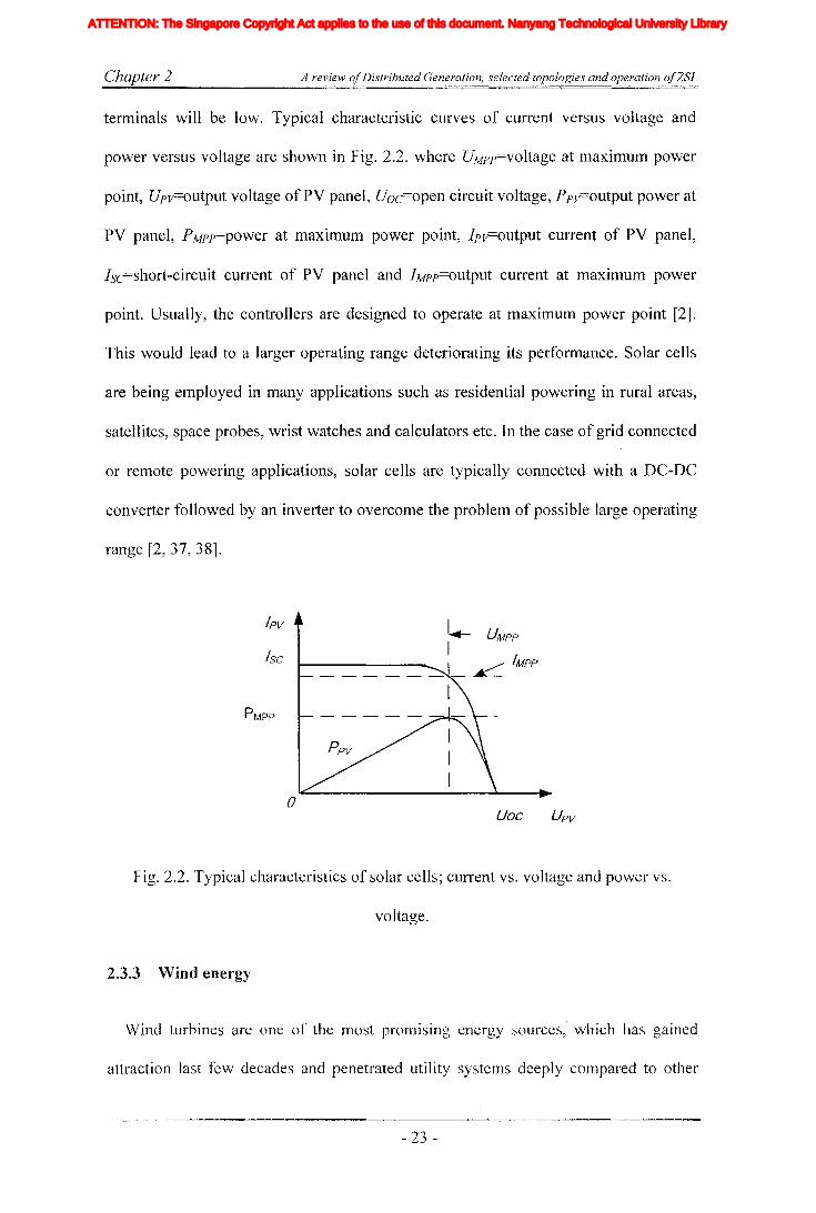
Chapter 2 A review ofDistributed Generation, selected topologies and operation ofZSI
terminals will be low. Typical characteristic curves of current versus voltage and
power versus voltage are shown in Fig. 2.2. where UMPp=voltage at maximum power
point, Upv=output voltage ofPV panel, Uoc=open circuit voltage, Ppv=output power at
PV panel, PMPp=power at maximum power point, Ipv=output current of PV panel,
Isc=short-circuit current of PV panel and IMPp=output current at maximum power
point. Usually, the controllers are designed to operate at maximum power point [2].
This would lead to a larger operating range deteriorating its performance. Solar cells
are being employed in many applications such as residential powering in rural areas,
satellites, space probes, wrist watches and calculators etc. In the case of grid connected
or remote powering applications, solar cells are typically connected with a DC-DC
converter followed by an inverter to overcome the problem of possible large operating
range [2, 37, 38].
/sc
PMPP
oVac Upv
Fig. 2.2. Typical characteristics of solar cells; current vs. voltage and power vs.
voltage.
2.3.3 Wind energy
Wind turbines are one of the most promising energy sources, which has gained
attraction last few decades and penetrated utility systems deeply compared to other
- 23 -
Iiq
Iod
Ioq
I odq
I max
1,Ie, Ici,Ic2IDC
IL_m
I MPP
IpvI scITHD
IzI Zn
lap*lap
Ia,Ip,IoIa *, Ip*,10*
Iah,Iphlin
12n
I;
afJ axis currentafJ axis reference currentafJO axis current componentsafJO axis reference current componentsafJ axis harmonic current componentsNeutral current of inverter 1Neutral current of inverter 2Zero sequence reference current
Average Z-source inductor currentPerturbed Z-source inductor current
Perturbed load currentConstantGain factor of fifth harmonics filterGain factor of seventh harmonics filterGain factor of eleventh harmonics filterDC side controller proportional gain of PI controllerDC side controller integral gain of PI controllerGain of the inverterIntegral gain of PI controller in current controllerGain of the hth resonance filterProportional gain of AC side inner loop controllerProportional gain of PI controller in current controllerProportional gain of zero sequence resonance controllerIntegral gain of the resonance controllerIntegral gain of the zero sequence resonance controllerIntegral gain of the hth resonance controllerProportional gain of AC side PI controllerIntegral gain of the AC side PI controllerMultiplying factor for harmonics eliminationDC side filter inductanceLoad inductanceNeutral inductanceGrid inductanceLeakage inductance of transformer
XVII
ATTENTION: The Singapore Copyright Act applies to the use of this document. Nanyang Technological University Library

Chapter 2 A review ojDistributed Generation, selected topologies and operation ojZSI
renewable sources [2, 10, 11]. These turbines are installed onshore or offshore, or
sometimes as a wind farm where large number of turbines are installed and connected
together. Wind turbine would transfer the linear moving wind energy into rotational
energy by the function P=O.5pJrRr2v3Cp. Where P = power, p =air density, Rr=
turbine radius, v = wind speed, and Cp= turbine power coefficient. On the other hand
Cp is a function only of the tip speed ratio A where the variation of Cp with A is given
in Fig. 2.3. The tip speed needs to be maintained at optimal value in order to extract
maximum power.
l=>-
v 0.4+-Jc0)
'0 0.3tE0) 0.20()
'-0) 0.1~00..
2 4 6 8 10 12Tip speed ratio A
Fig. 2.3. Variation of power coefficient Cp with tip speed ratio A.
Typically, wind turbines consist of aerodynamically designed three blades which
are positioned in horizontal axis and whole system is mounted on a tower. The
rotational mechanical energy is converted to electrical energy with the use of a
generator. In some cases, energy is transmitted through a gear box to change the speed.
Basically, wind turbines are controlled mechanically, either by pitch controlling or
stall controlling. Pitch controlling is more complex where the wind speed is
continuously measured and blades are adjusted accordingly in order to capture energy
efficiently. Also it would protect the turbine from high wind speeds. This control
method is more efficient compared to stall control. The stall controlled blades are
- 24 -
Iiq
Iod
Ioq
I odq
I max
1,Ie, Ici,Ic2IDC
IL_m
I MPP
IpvI scITHD
IzI Zn
lap*lap
Ia,Ip,IoIa *, Ip*,10*
Iah,Iphlin
12n
I;
afJ axis currentafJ axis reference currentafJO axis current componentsafJO axis reference current componentsafJ axis harmonic current componentsNeutral current of inverter 1Neutral current of inverter 2Zero sequence reference current
Average Z-source inductor currentPerturbed Z-source inductor current
Perturbed load currentConstantGain factor of fifth harmonics filterGain factor of seventh harmonics filterGain factor of eleventh harmonics filterDC side controller proportional gain of PI controllerDC side controller integral gain of PI controllerGain of the inverterIntegral gain of PI controller in current controllerGain of the hth resonance filterProportional gain of AC side inner loop controllerProportional gain of PI controller in current controllerProportional gain of zero sequence resonance controllerIntegral gain of the resonance controllerIntegral gain of the zero sequence resonance controllerIntegral gain of the hth resonance controllerProportional gain of AC side PI controllerIntegral gain of the AC side PI controllerMultiplying factor for harmonics eliminationDC side filter inductanceLoad inductanceNeutral inductanceGrid inductanceLeakage inductance of transformer
XVII
ATTENTION: The Singapore Copyright Act applies to the use of this document. Nanyang Technological University Library

Chapter 2 A review ofDistributed Generation, selected topologies and operation ofZSJ
fixed at constant pitch angle and it is not changed during the operation. Stall is a
simple aerodynamic effect that separates the airflow from aerofoil when the turbine
runs at a constant speed and when the wind speed increasing. This would change the
angle of attack and limit the wind power captured and thereby protecting the turbine
from high wind speed. I-Iowever, due to randomness of the wind availability and again
when these wind turbines are operated to capture maximum power, the operating
voltage and frequency tend to vary making the output unsuitable for grid connection
demanding power conditioning before being consumed.
There are many generating topologies commonly used in wind turbines such as
induction generators, synchronous generators and permanent magnet synchronous
generators. Some generators are connected directly to the grid while others use power
electronic interfaces [11]. Power electronic interfaces have to be selected depending
on the generator used and adopted controlling method. Generally, induction generators
are used with fixed speed wind turbines and power is limited mechanically with pitch
or stall controlling. Other type is variable speed wind turbines which controls the pitch
and use power electronic interface at the output of the generator which can be a
synchronous generator, permanent magnet synchronous generator or doubly fed
induction generator. There are different power electronic converters topologies that are
employed in interfacing these wind generators to overCOlne problems of variation in
frequency and voltage. In the case of synchronous generators, full rated power
electronic converters are used. Usually, they can be an AC to DC converters followed
by inverters or simple rectifiers followed by DC to DC converters and then inverters
[10]. For induction generators, there are two possibilities; it can have an AC to DC
converters folJowed by a DC to AC inverters in both stator and rotor or only AC to DC
followed by aDC to AC inverters connected in the rotor of induction generators. In
- 25 -
Iiq
Iod
Ioq
I odq
I max
1,Ie, Ici,Ic2IDC
IL_m
I MPP
IpvI scITHD
IzI Zn
lap*lap
Ia,Ip,IoIa *, Ip*,10*
Iah,Iphlin
12n
I;
afJ axis currentafJ axis reference currentafJO axis current componentsafJO axis reference current componentsafJ axis harmonic current componentsNeutral current of inverter 1Neutral current of inverter 2Zero sequence reference current
Average Z-source inductor currentPerturbed Z-source inductor current
Perturbed load currentConstantGain factor of fifth harmonics filterGain factor of seventh harmonics filterGain factor of eleventh harmonics filterDC side controller proportional gain of PI controllerDC side controller integral gain of PI controllerGain of the inverterIntegral gain of PI controller in current controllerGain of the hth resonance filterProportional gain of AC side inner loop controllerProportional gain of PI controller in current controllerProportional gain of zero sequence resonance controllerIntegral gain of the resonance controllerIntegral gain of the zero sequence resonance controllerIntegral gain of the hth resonance controllerProportional gain of AC side PI controllerIntegral gain of the AC side PI controllerMultiplying factor for harmonics eliminationDC side filter inductanceLoad inductanceNeutral inductanceGrid inductanceLeakage inductance of transformer
XVII
ATTENTION: The Singapore Copyright Act applies to the use of this document. Nanyang Technological University Library
Chapter 2 A review ofDistributed Generation, selected topologies and operation ofZSI
summary, all those topologies use a combination of two or more power electronic
converters, making the overall process inefficient and difficult to control as identified
in the first section of this chapter. This leaves the space for development of single
stage topologies in integrating wind power generating systems.
2.3.4 Ultra capacitors
Ultra capacitor is a promising short-term energy storage device that can be used in
many industrial applications. It has very high capacitance in the range of Farads and
takes longer time to charge or discharge compared to normal capacitors. It has many
advantages like high power density, maintenance free and easiness in usage compared
to batteries. They are safer as they do not explode even if the terminals are short
circuited. On the other hand, ultra capacitors are not suitable for AC applications as
they do not perform well under the presence of high ripple currents [39]. So far ultra
capacitors are developed only to operate in low voltages. Therefore, they are
connected In senes to obtain the required voltage level In power converter
applications. The disadvantage of ultra capacitor is that its voltage would vary in a
large range during discharging. This would limit the operating range if simple VSI is
employed. Therefore, DC-DC converters followed by inverters or a single stage
topology like ZSI topology with buck-boost capability would be appropriate in
interfacing with loads [40].
2.3.5 Battery banks
Battery banks are used to store the electrical energy for future use. There are many
types of batteries commercially available but lead-acid batteries are frequently used
with renewable sources, automobiles and telecommunication equipments etc. They
generate voltage by a chemical reaction with two unlike 111aterials irnmense in an
- 26-
Iiq
Iod
Ioq
I odq
I max
1,Ie, Ici,Ic2IDC
IL_m
I MPP
IpvI scITHD
IzI Zn
lap*lap
Ia,Ip,IoIa *, Ip*,10*
Iah,Iphlin
12n
I;
afJ axis currentafJ axis reference currentafJO axis current componentsafJO axis reference current componentsafJ axis harmonic current componentsNeutral current of inverter 1Neutral current of inverter 2Zero sequence reference current
Average Z-source inductor currentPerturbed Z-source inductor current
Perturbed load currentConstantGain factor of fifth harmonics filterGain factor of seventh harmonics filterGain factor of eleventh harmonics filterDC side controller proportional gain of PI controllerDC side controller integral gain of PI controllerGain of the inverterIntegral gain of PI controller in current controllerGain of the hth resonance filterProportional gain of AC side inner loop controllerProportional gain of PI controller in current controllerProportional gain of zero sequence resonance controllerIntegral gain of the resonance controllerIntegral gain of the zero sequence resonance controllerIntegral gain of the hth resonance controllerProportional gain of AC side PI controllerIntegral gain of the AC side PI controllerMultiplying factor for harmonics eliminationDC side filter inductanceLoad inductanceNeutral inductanceGrid inductanceLeakage inductance of transformer
XVII
ATTENTION: The Singapore Copyright Act applies to the use of this document. Nanyang Technological University Library
Chapter 2 A review ojDistributed Generation, selected topologies and operation ojZSl
electrolyte. In the case of lead acid battery, lead plates are used as positive and
negative terminals and solution of sulfuric acid and water is used as the electrolyte.
Lead batteries have long life but need constant maintenance since the level of
electrolyte has to be maintained at particular level to avoid damaging the plates.
Usually, a battery banks are made by connecting several batteries in series or parallel
in order to achieve the required level of voltage or current.
2.4 Power quality problems associated with DG
Modern day power systems have developed to a very complex level with the
increase of energy demand, geographical spread of loads and generating sources and
with the use of interconnected systems to increase the reliability. Also integration of
large amount of sources in distribution level has made the power system operation in a
different dimension demanding reassessing of many system operations. Power quality,
stability and reliability are important factors in power system operation. Power quality
is a broad concept and it is defined based on the voltage and current magnitude,
frequency and power delivered.
Among power quality issues, sags, swells, underlover voltages, power interruptions,
transients, flicker, harmonics and frequency variations are predominant. These are
further categorized into change in magnitude, change in frequency and change in
waveform shape. This section introduces some of the power quality issues that are
addressed in this thesis.
2.4.1 Unbalance
In three phase systellls, voltage supply should be balanced. That is, lllagnitudes of
the three phase voltage components should be equal in magnitude and they should be
- 27 -
Iiq
Iod
Ioq
I odq
I max
1,Ie, Ici,Ic2IDC
IL_m
I MPP
IpvI scITHD
IzI Zn
lap*lap
Ia,Ip,IoIa *, Ip*,10*
Iah,Iphlin
12n
I;
afJ axis currentafJ axis reference currentafJO axis current componentsafJO axis reference current componentsafJ axis harmonic current componentsNeutral current of inverter 1Neutral current of inverter 2Zero sequence reference current
Average Z-source inductor currentPerturbed Z-source inductor current
Perturbed load currentConstantGain factor of fifth harmonics filterGain factor of seventh harmonics filterGain factor of eleventh harmonics filterDC side controller proportional gain of PI controllerDC side controller integral gain of PI controllerGain of the inverterIntegral gain of PI controller in current controllerGain of the hth resonance filterProportional gain of AC side inner loop controllerProportional gain of PI controller in current controllerProportional gain of zero sequence resonance controllerIntegral gain of the resonance controllerIntegral gain of the zero sequence resonance controllerIntegral gain of the hth resonance controllerProportional gain of AC side PI controllerIntegral gain of the AC side PI controllerMultiplying factor for harmonics eliminationDC side filter inductanceLoad inductanceNeutral inductanceGrid inductanceLeakage inductance of transformer
XVII
ATTENTION: The Singapore Copyright Act applies to the use of this document. Nanyang Technological University Library

Chapter 2 A review ofDistributed Generation, selected topologies and operation ofZSI
apart by 120 electrical degrees. Any deviation in magnitude or phase angle results in
unbalance condition. In other words, if the system voltages are divided into
symmetrical components then only the positive sequence should be present. If the
other sequence components are present, it is defined as the system is unbalanced. To
measure and to quantify the unbalance, unbalance factor is defined. However, in
different standards it is defined in different ways, lEe (International Electrotechnical
commission) standards define it as magnitude of negative sequence component upon
magnitude of positive sequence component and it is given in (2-1), then in equation (2-
2) gives the NEMA (National Electrical Manufacturers Association of USA) definition
of unbalance.
Negative sequence unbalance factor == ~N ==~p
(2-1)
Maximum deviation from mean of (V l , ~ , V )Voltage unbalance - (.) a? c ca
Mean of r:b' ~c , ~'a(2-2)
Mainly, unbalances result from unequal impedances, unequal distribution of single-
phase loads and unsymmetrical grid faults at the far end of a distribution network.
There are many disadvantages arising from unbalances and major one is malfunction
of some loads. The effects on induction motor loads are significant, even with small
amou~t of unbalance in voltage, the unbalance current drawn by the motor is
significant and could result in reduction in efficiency and insulation life and motor
would run noisily due to torque and speed pulsations. Other major influence is on the
rectifier loads, where unbalance would result in increased harmonics. Unbalances also
- 28 -
Iiq
Iod
Ioq
I odq
I max
1,Ie, Ici,Ic2IDC
IL_m
I MPP
IpvI scITHD
IzI Zn
lap*lap
Ia,Ip,IoIa *, Ip*,10*
Iah,Iphlin
12n
I;
afJ axis currentafJ axis reference currentafJO axis current componentsafJO axis reference current componentsafJ axis harmonic current componentsNeutral current of inverter 1Neutral current of inverter 2Zero sequence reference current
Average Z-source inductor currentPerturbed Z-source inductor current
Perturbed load currentConstantGain factor of fifth harmonics filterGain factor of seventh harmonics filterGain factor of eleventh harmonics filterDC side controller proportional gain of PI controllerDC side controller integral gain of PI controllerGain of the inverterIntegral gain of PI controller in current controllerGain of the hth resonance filterProportional gain of AC side inner loop controllerProportional gain of PI controller in current controllerProportional gain of zero sequence resonance controllerIntegral gain of the resonance controllerIntegral gain of the zero sequence resonance controllerIntegral gain of the hth resonance controllerProportional gain of AC side PI controllerIntegral gain of the AC side PI controllerMultiplying factor for harmonics eliminationDC side filter inductanceLoad inductanceNeutral inductanceGrid inductanceLeakage inductance of transformer
XVII
ATTENTION: The Singapore Copyright Act applies to the use of this document. Nanyang Technological University Library

Chapter 2 A review ojDistributed Generation, selected topologies and operation ojZSJ
generate uncharacteristic harmonics and thereby reducing the effectiveness of the
designed filters.
However, in practical power systems unbalance cannot be mitigated to zero as the
randomness of connection and disconnection of single phase loads. However, it can be
reduced by properly balancing single phase loads and also with connection of SVC or
APF with special control algorithms [41, 42].
2.4.2 Faults, sags and interruptions
For proper functioning of consumer loads, it is required to be supplied a voltage that
lies within the acceptable range. Voltage variations, such as voltage sags and
momentary interruptions are two of the most important power quality concerns for
customers. The impact to the customer depends on the voltage magnitude during the
disturbance and the sensitivity of the customer equipment. The IEEE Std. 1159-1995
gives the definition to all possible fault conditions. Faults are divided into two
categories based on the duration namely, long term and short term interruptions. Short
term disturbances are further divided into instantaneous, momentary, and telnporary
depending on the time period. Depending on the voltage magnitude these faults can be
sags, swells or interruptions. Long term interruptions can be sustained interruption,
under voltage, or over voltage depending upon their magnitude. However, voltage sags
are the most important power quality problem experienced by most industrial
customers [27, 29, 43]. As their loads such as adjustable-speed drive (ASD) controls,
robotics, and programmable logic controllers etc. tend to malfunction. Furthennore,
most of these equipments are used in applications that are critical to overall process,
resulting in colossal econonlic loss. Therefore, corrective and preventive actions have
to be taken. There are many power electronic solutions proposed to mitigate and
- 29-
Iiq
Iod
Ioq
I odq
I max
1,Ie, Ici,Ic2IDC
IL_m
I MPP
IpvI scITHD
IzI Zn
lap*lap
Ia,Ip,IoIa *, Ip*,10*
Iah,Iphlin
12n
I;
afJ axis currentafJ axis reference currentafJO axis current componentsafJO axis reference current componentsafJ axis harmonic current componentsNeutral current of inverter 1Neutral current of inverter 2Zero sequence reference current
Average Z-source inductor currentPerturbed Z-source inductor current
Perturbed load currentConstantGain factor of fifth harmonics filterGain factor of seventh harmonics filterGain factor of eleventh harmonics filterDC side controller proportional gain of PI controllerDC side controller integral gain of PI controllerGain of the inverterIntegral gain of PI controller in current controllerGain of the hth resonance filterProportional gain of AC side inner loop controllerProportional gain of PI controller in current controllerProportional gain of zero sequence resonance controllerIntegral gain of the resonance controllerIntegral gain of the zero sequence resonance controllerIntegral gain of the hth resonance controllerProportional gain of AC side PI controllerIntegral gain of the AC side PI controllerMultiplying factor for harmonics eliminationDC side filter inductanceLoad inductanceNeutral inductanceGrid inductanceLeakage inductance of transformer
XVII
ATTENTION: The Singapore Copyright Act applies to the use of this document. Nanyang Technological University Library

Chapter 2 A review ojDistributed Generation, selected topologies and operation ojZSl
prevent effects of these power quality problems. Some of the critical equipments are
supplied with UPS systems [44], however these are very expensive. Large industrial
customers and utilities use ride-through systems like DVR and unified power quality
compensator (UPQC) [1,45, 46].
2.4.3 Harmonics
Presence of harmonic would distort the waveform quality of voltages. In
mathematical view point, harmonics can be defined as Fourier series components of
distorted periodic signals other than fundamental component. That is harmonic
frequencies are integer multiples of the fundamental frequency. Decades ago,
harmonics was not a bigger concern and the amount of harmonics present in the power
system was less. However, at present the amount of nonlinear loads has increased
immensely and they are the main source of harmonic generation, such as VSD,
charging circuits, computer power supplies etc. Presence of high levels of harmonics
could trigger resonance in line inductors and power factor correction capacitors. Also
it could lead to malfunction of sensitive loads, false tripping of circuit breakers, large
currents in neutral conductors, poor power factor correction and over heating of
transformers and thereby reducing their life time.
There are different standards imposed by the regulatory bodies on the consumer
loads as well as on the utility specifying the harmonic levels that have to be
maintained. Different harmonic standards are available like IEEE 519, IEEE 929, G5/4
and lEe 61000 etc. Large consumers and utilities adopt different harmonic
cOlnpensation strategies to remove harmonics. One method is to use passive filters
tuned to a particular harmonic, that would create a low impedance path for that
particular harmonic frequency [21]. Another commonly used method is to use APF's
- 30-
Iiq
Iod
Ioq
I odq
I max
1,Ie, Ici,Ic2IDC
IL_m
I MPP
IpvI scITHD
IzI Zn
lap*lap
Ia,Ip,IoIa *, Ip*,10*
Iah,Iphlin
12n
I;
afJ axis currentafJ axis reference currentafJO axis current componentsafJO axis reference current componentsafJ axis harmonic current componentsNeutral current of inverter 1Neutral current of inverter 2Zero sequence reference current
Average Z-source inductor currentPerturbed Z-source inductor current
Perturbed load currentConstantGain factor of fifth harmonics filterGain factor of seventh harmonics filterGain factor of eleventh harmonics filterDC side controller proportional gain of PI controllerDC side controller integral gain of PI controllerGain of the inverterIntegral gain of PI controller in current controllerGain of the hth resonance filterProportional gain of AC side inner loop controllerProportional gain of PI controller in current controllerProportional gain of zero sequence resonance controllerIntegral gain of the resonance controllerIntegral gain of the zero sequence resonance controllerIntegral gain of the hth resonance controllerProportional gain of AC side PI controllerIntegral gain of the AC side PI controllerMultiplying factor for harmonics eliminationDC side filter inductanceLoad inductanceNeutral inductanceGrid inductanceLeakage inductance of transformer
XVII
ATTENTION: The Singapore Copyright Act applies to the use of this document. Nanyang Technological University Library
Chapter 2 A review ofDistributed Generation, selected topologies and operation ofZSI
to compensate harmonics [30, 47]. The function of the APF is similar to the passive
filters where it would create a low impedance path for the harmonic currents.
2.5 Converter topologies for Distributed Generation
In the previous two sections various sources and their characteristics and also power
quality issues have been discussed. This section focuses on different power electronic
topologies that are commonly employed to interface those energy sources and storages
and also topologies that are used to mitigate some of the power quality problems.
2.5.1 Topologies for mitigating the power quality issues
As described in preVIOUS sections, there are many power quality problems
associated with utility grids. As mentioned in the first chapter, this thesis also focuses
on addressing some of the power quality issues pertaining to the distribution systems.
Therefore, SOITIe of the basic topologies that are commonly used to address these
power quality issues are introduced in this section.
2.5.1.1 UPS
Uninterruptible power supplies (UPS) are power supplies that continuously supply
power to a load or act as a battery backup. They are commonly used with sensitive
loads such as medical instruments, expensive computer systems, and defense
equipment to get a reliable supply. There are many types of UPS systems commonly in
use. Mainly they are divided into offline and online or line interactive. The block
diagram representation is shown in Fig. 2.4. They consist of rectifier or charger and
battery bank followed by an inverter and in case of offline or line interactive UPS it
uses a static switch [48]. The offline UPS systems are activated only when there is a
fault in the power systelTI and it will connect automatically by disconnecting the mains
- 31 -
Iiq
Iod
Ioq
I odq
I max
1,Ie, Ici,Ic2IDC
IL_m
I MPP
IpvI scITHD
IzI Zn
lap*lap
Ia,Ip,IoIa *, Ip*,10*
Iah,Iphlin
12n
I;
afJ axis currentafJ axis reference currentafJO axis current componentsafJO axis reference current componentsafJ axis harmonic current componentsNeutral current of inverter 1Neutral current of inverter 2Zero sequence reference current
Average Z-source inductor currentPerturbed Z-source inductor current
Perturbed load currentConstantGain factor of fifth harmonics filterGain factor of seventh harmonics filterGain factor of eleventh harmonics filterDC side controller proportional gain of PI controllerDC side controller integral gain of PI controllerGain of the inverterIntegral gain of PI controller in current controllerGain of the hth resonance filterProportional gain of AC side inner loop controllerProportional gain of PI controller in current controllerProportional gain of zero sequence resonance controllerIntegral gain of the resonance controllerIntegral gain of the zero sequence resonance controllerIntegral gain of the hth resonance controllerProportional gain of AC side PI controllerIntegral gain of the AC side PI controllerMultiplying factor for harmonics eliminationDC side filter inductanceLoad inductanceNeutral inductanceGrid inductanceLeakage inductance of transformer
XVII
ATTENTION: The Singapore Copyright Act applies to the use of this document. Nanyang Technological University Library

Chapter 2 A review ofDistributed Generation, selected topologies and operation ofZSJ
supply using the static switch. Whereas online UPS systems continuously power the
load and work as a power conditioner which would be able to remove the other power
quality problems [46].
(a)
Static switch
(b)
~Static switch
~
Fig. 2.4. UPS systems, (a) on line (b) offline (c) line interactive
2.5.1.2 DVR
Dynamic voltage restorer is a power electronic solution used to improve the quality
of supply when the system undergoes grid faults and sags. Generally, this is used by
the utilities and consumers to provide continuous power to sensitive loads. This is
achieved by injecting series voltage to the system, when a fault or sag occurs. The
DVR is controlled to maintain the required voltage level at the load bus and it would
enhance the voltage quality to the load [49]. Here the injected voltage from DVR is
- 32 -
Iiq
Iod
Ioq
I odq
I max
1,Ie, Ici,Ic2IDC
IL_m
I MPP
IpvI scITHD
IzI Zn
lap*lap
Ia,Ip,IoIa *, Ip*,10*
Iah,Iphlin
12n
I;
afJ axis currentafJ axis reference currentafJO axis current componentsafJO axis reference current componentsafJ axis harmonic current componentsNeutral current of inverter 1Neutral current of inverter 2Zero sequence reference current
Average Z-source inductor currentPerturbed Z-source inductor current
Perturbed load currentConstantGain factor of fifth harmonics filterGain factor of seventh harmonics filterGain factor of eleventh harmonics filterDC side controller proportional gain of PI controllerDC side controller integral gain of PI controllerGain of the inverterIntegral gain of PI controller in current controllerGain of the hth resonance filterProportional gain of AC side inner loop controllerProportional gain of PI controller in current controllerProportional gain of zero sequence resonance controllerIntegral gain of the resonance controllerIntegral gain of the zero sequence resonance controllerIntegral gain of the hth resonance controllerProportional gain of AC side PI controllerIntegral gain of the AC side PI controllerMultiplying factor for harmonics eliminationDC side filter inductanceLoad inductanceNeutral inductanceGrid inductanceLeakage inductance of transformer
XVII
ATTENTION: The Singapore Copyright Act applies to the use of this document. Nanyang Technological University Library
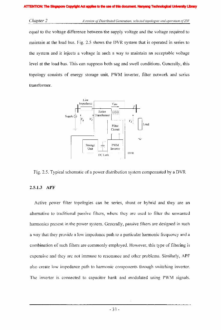
Chapter 2 A review ojDistributed Generation, selected topologies and operation ojZSI
equal to the voltage difference between the supply voltage and the voltage required to
maintain at the load bus. Fig. 2.5 shows the DVR system that is operated in series to
the system and it injects a voltage in such a way to maintain an acceptable voltage
level at the load bus. This can suppress both sag and swell conditions. Generally, this
topology consists of energy storage unit, PWM inverter, filter network and series
transformer.
LineImpedance
Supply'\..,
StorageUnit
DC Link
FilterCircuit
PWMInverter
DVR
Load
Fig. 2.5. Typical schematic of a power distribution system compensated by a DVR
2.5.1.3 APF
Active power filter topologies can be serIes, shunt or hybrid and they are an
alternative to traditional passive filters, where they are used to filter the unwanted
harmonics present in the power system. Generally, passive filters are designed in such
a way that they provide a low impedance path to a particular harmonic frequency and a
combination of such filters are commonly employed. However, this type of filtering is
expensive and they are not inllTIUne to resonance and other problems. Similarly, APF
also create low impedance path to harmonic components through switching inverter.
The inverter is connected to capacitor bank and modulated using PWM signals.
- 33 -
Iiq
Iod
Ioq
I odq
I max
1,Ie, Ici,Ic2IDC
IL_m
I MPP
IpvI scITHD
IzI Zn
lap*lap
Ia,Ip,IoIa *, Ip*,10*
Iah,Iphlin
12n
I;
afJ axis currentafJ axis reference currentafJO axis current componentsafJO axis reference current componentsafJ axis harmonic current componentsNeutral current of inverter 1Neutral current of inverter 2Zero sequence reference current
Average Z-source inductor currentPerturbed Z-source inductor current
Perturbed load currentConstantGain factor of fifth harmonics filterGain factor of seventh harmonics filterGain factor of eleventh harmonics filterDC side controller proportional gain of PI controllerDC side controller integral gain of PI controllerGain of the inverterIntegral gain of PI controller in current controllerGain of the hth resonance filterProportional gain of AC side inner loop controllerProportional gain of PI controller in current controllerProportional gain of zero sequence resonance controllerIntegral gain of the resonance controllerIntegral gain of the zero sequence resonance controllerIntegral gain of the hth resonance controllerProportional gain of AC side PI controllerIntegral gain of the AC side PI controllerMultiplying factor for harmonics eliminationDC side filter inductanceLoad inductanceNeutral inductanceGrid inductanceLeakage inductance of transformer
XVII
ATTENTION: The Singapore Copyright Act applies to the use of this document. Nanyang Technological University Library
Chapter 2 A review ofDistributed Generation, selected topologies and operation ofZSI
Appropriate control algorithm has to be developed to eliminate particular harmonic or
all the harmonics components associated with the load or customer bus [20, 47].
2.5.1.4 SVC
Static var compensator (SVC) is power quality improvement device that used to
control the reactive power flow. This type of device is commonly used in substations
to control the power flow in transmission lines, and also by large consumers to
improve power factor. Generally, SVC comprises of shunt connected capacitor bank
and variable inductor bank of which effective impedance is varied by switching of
connected thyristors. SVC is capable of providing both inductive and capacitive
reactive power to the system. Although its main function is to correct the reactive
power flow, it also can be used to balance the line voltage at the connecting bus with
the use of special control algorithms. This makes it more versatile power quality
compensator [41].
2.5.1.5 Flexible DG systems
Flexible Distributed generation schemes are gaining more and more attraction in the
recent past. Increased penetration of DG systems could make the distribution system
unstable as they are not designed to support other functions of power system operation
such as reactive power generation, harmonic and unbalance mitigation. Also some of
these systems have unused capacity left due to unavailability of source energy like
changes in sun light, changes in wind etc. and also due to demand side consideration
like low power demand or low prices. In such scenarios, the inverters used in power
conversion can be left with some excess capacity which could be used to provide
certain ancillary functions like harmonic and unbalance mitigation of the power
distribution system. This will allow the DG systelTI for better utilization of resources
- 34 -
Iiq
Iod
Ioq
I odq
I max
1,Ie, Ici,Ic2IDC
IL_m
I MPP
IpvI scITHD
IzI Zn
lap*lap
Ia,Ip,IoIa *, Ip*,10*
Iah,Iphlin
12n
I;
afJ axis currentafJ axis reference currentafJO axis current componentsafJO axis reference current componentsafJ axis harmonic current componentsNeutral current of inverter 1Neutral current of inverter 2Zero sequence reference current
Average Z-source inductor currentPerturbed Z-source inductor current
Perturbed load currentConstantGain factor of fifth harmonics filterGain factor of seventh harmonics filterGain factor of eleventh harmonics filterDC side controller proportional gain of PI controllerDC side controller integral gain of PI controllerGain of the inverterIntegral gain of PI controller in current controllerGain of the hth resonance filterProportional gain of AC side inner loop controllerProportional gain of PI controller in current controllerProportional gain of zero sequence resonance controllerIntegral gain of the resonance controllerIntegral gain of the zero sequence resonance controllerIntegral gain of the hth resonance controllerProportional gain of AC side PI controllerIntegral gain of the AC side PI controllerMultiplying factor for harmonics eliminationDC side filter inductanceLoad inductanceNeutral inductanceGrid inductanceLeakage inductance of transformer
XVII
ATTENTION: The Singapore Copyright Act applies to the use of this document. Nanyang Technological University Library

Chapter 2 A review ofDistributed Generation, selected topologies and operation ofZSI
and thereby reducing the price of operation. In order to achieve this, topological and
control algorithms need to be changed [19, 21].
2.5.2 DG interfacing topologies
Power electronic converters are employed in almost all electronic equipment. They
are employed in significant amounts even in the power systems. Some of these
converters are employed to grid connection of generation and storage devices, FACTS
(flexible AC transmission systems), STATCOM (Static compensator), UPFC (unified
power flow controller), and APF etc. In all these devices, inverter is a fundamental
building block [44]. In most of these applications it is required to convert power from
AC-DC or DC-AC. Both voltage source and current source PWM inverters are
employed in converting DC voltage to a AC and both these converters have matured in
structure of power circuit, modulation methods and control strategies [50].
In designing power converters for DO, emphasis should be given to the following
factors: source characteristics, such as energy availability, load demand and load
characteristics, whether the inverter is connected to grid or generated power consumed
in site. There are other factors like how to address the protection issues in the inverter
side and in the load side and power quality aspects minimizing the harmonics and
voltage dips etc. need to be considered. Inverter design has to be unique to energy
source and it needs to address specific problems associated with each source. In this
section, popular converter options are considered for DO.
2.5.2.1 Voltage source inverter
Voltage source inverter (VSI) is the n10st common inverter topology. Fig. 2.6 shows
the general configuration of VSI, which is usually supplied from a relatively large
- 35 -
Iiq
Iod
Ioq
I odq
I max
1,Ie, Ici,Ic2IDC
IL_m
I MPP
IpvI scITHD
IzI Zn
lap*lap
Ia,Ip,IoIa *, Ip*,10*
Iah,Iphlin
12n
I;
afJ axis currentafJ axis reference currentafJO axis current componentsafJO axis reference current componentsafJ axis harmonic current componentsNeutral current of inverter 1Neutral current of inverter 2Zero sequence reference current
Average Z-source inductor currentPerturbed Z-source inductor current
Perturbed load currentConstantGain factor of fifth harmonics filterGain factor of seventh harmonics filterGain factor of eleventh harmonics filterDC side controller proportional gain of PI controllerDC side controller integral gain of PI controllerGain of the inverterIntegral gain of PI controller in current controllerGain of the hth resonance filterProportional gain of AC side inner loop controllerProportional gain of PI controller in current controllerProportional gain of zero sequence resonance controllerIntegral gain of the resonance controllerIntegral gain of the zero sequence resonance controllerIntegral gain of the hth resonance controllerProportional gain of AC side PI controllerIntegral gain of the AC side PI controllerMultiplying factor for harmonics eliminationDC side filter inductanceLoad inductanceNeutral inductanceGrid inductanceLeakage inductance of transformer
XVII
ATTENTION: The Singapore Copyright Act applies to the use of this document. Nanyang Technological University Library
Chapter 2 A review ofDistributed Generation, selected topologies and operation ofZSI
capacitor bank, a diode rectifier, a battery, a fuel cell or a solar cell. The converter has
a 6-switch H-bridge in three phase configuration. These switches are usually metal
oxide semiconductor field effect transistor (MOSFET) or insulated gate bipolar
transistor (IGBT) in low and medium power levels. However, in high power levels
gate tum off transistor (GTO) or thyristors are used with low switching frequency. The
switches are connected with anti-parallel diode to allow bidirectional current flow.
PWM schemes for VSI have been well developed, as sine PMW, space vector
modulation and specific harmonic eliminations methods are common. VSI is mainly
employed in UPS, FACTS, DVR and VSD motor drives as it gives good output
voltage with low harmonic levels. The main disadvantage of this converter is that it
shows buck type (step down) output voltage characteristic which limits the maximum
voltage that can be attained. This could lead to numerous problems such as limiting the
overdrive capability in motor drives and interruptions in supply of UPS systems when
source the DC voltage drops below a critical value. With silnple modulation methods,
the possible maximum output voltage is limited to half the DC bus voltage. However,
this can be improved up to 1.15 times the half the DC bus voltage before being over
modulated [51]. This is achieved by increase the linear region with mixing the triplen
harmonics into the modulation signal. Overall it can be concluded that a very large DC
supply is required. This requirement limits the usability of this inverter topology alone
in DG systems with low DC output voltage and output with large variations.
Moreover, it requires the use of dead tilne in switching signal to prevent the short
circuiting of the DC bus. This limits the switching frequency and the controller would
be con1plicated with the need of dead time. The output voltage of VSI may have larger
harmonic distortions especially with low switching frequency applications. This
requires the use of good output filtering network. However, employing a filter network
- 36 -
Iiq
Iod
Ioq
I odq
I max
1,Ie, Ici,Ic2IDC
IL_m
I MPP
IpvI scITHD
IzI Zn
lap*lap
Ia,Ip,IoIa *, Ip*,10*
Iah,Iphlin
12n
I;
afJ axis currentafJ axis reference currentafJO axis current componentsafJO axis reference current componentsafJ axis harmonic current componentsNeutral current of inverter 1Neutral current of inverter 2Zero sequence reference current
Average Z-source inductor currentPerturbed Z-source inductor current
Perturbed load currentConstantGain factor of fifth harmonics filterGain factor of seventh harmonics filterGain factor of eleventh harmonics filterDC side controller proportional gain of PI controllerDC side controller integral gain of PI controllerGain of the inverterIntegral gain of PI controller in current controllerGain of the hth resonance filterProportional gain of AC side inner loop controllerProportional gain of PI controller in current controllerProportional gain of zero sequence resonance controllerIntegral gain of the resonance controllerIntegral gain of the zero sequence resonance controllerIntegral gain of the hth resonance controllerProportional gain of AC side PI controllerIntegral gain of the AC side PI controllerMultiplying factor for harmonics eliminationDC side filter inductanceLoad inductanceNeutral inductanceGrid inductanceLeakage inductance of transformer
XVII
ATTENTION: The Singapore Copyright Act applies to the use of this document. Nanyang Technological University Library
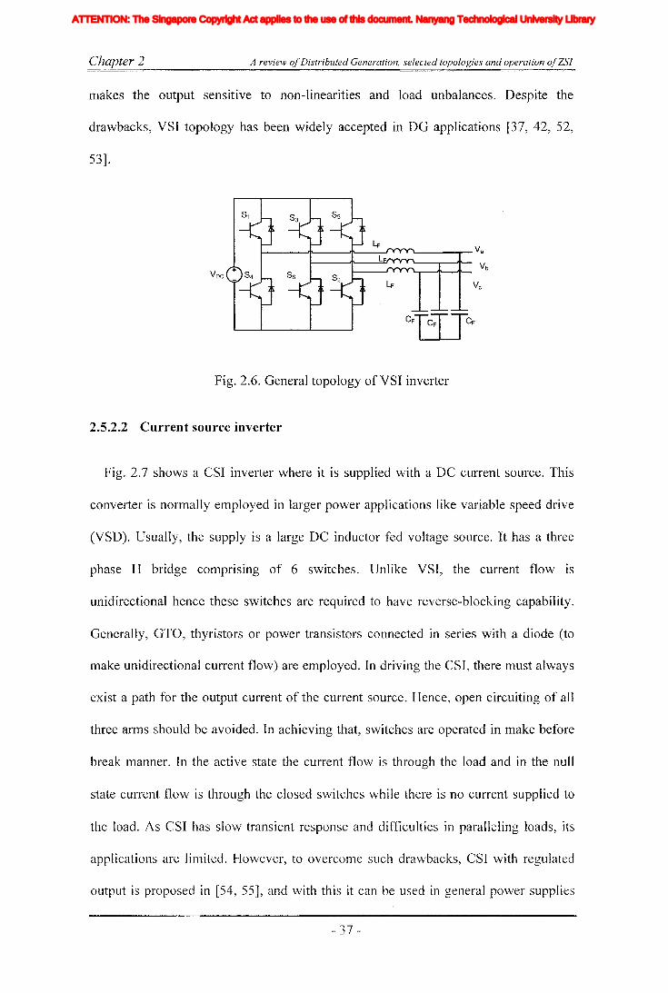
Chapter 2 A review ojDistributed Generation, selected topologies and operation ojZSI
makes the output sensitive to non-linearities and load unbalances. Despite the
drawbacks, VSI topology has been widely accepted in DG applications [37, 42, 52,
53].
VDC
Fig. 2.6. General topology of VSI inverter
2.5.2.2 Current source inverter
Fig. 2.7 shows a CSI inverter where it is supplied with a DC current source. This
converter is normally employed in larger power applications like variable speed drive
(VSD). Usually, the supply is a large DC inductor fed voltage source. It has a three
phase H bridge con1prising of 6 switches. Unlike VSI, the current flow is
unidirectional hence these switches are required to have reverse-blocking capability.
Generally, GTO, thyristors or power transistors connected in series with a diode (to
make unidirectional current flow) are employed. In driving the CSI, there must always
exist a path for the output current of the current source. Hence, open circuiting of all
three arms should be avoided. In achieving that, switches are operated in make before
break manner. In the active state the current flow is through the load and in the null
state current flow is through the closed switches while there is no current supplied to
the load. As CSI has slow transient response and difficulties in paralleling loads, its
applications are lilllited. I-Iowever, to overcome such drawbacks, CSI with regulated
output is proposed in [54, 55], and with this it can be used in general power supplies
- 37 -
Iiq
Iod
Ioq
I odq
I max
1,Ie, Ici,Ic2IDC
IL_m
I MPP
IpvI scITHD
IzI Zn
lap*lap
Ia,Ip,IoIa *, Ip*,10*
Iah,Iphlin
12n
I;
afJ axis currentafJ axis reference currentafJO axis current componentsafJO axis reference current componentsafJ axis harmonic current componentsNeutral current of inverter 1Neutral current of inverter 2Zero sequence reference current
Average Z-source inductor currentPerturbed Z-source inductor current
Perturbed load currentConstantGain factor of fifth harmonics filterGain factor of seventh harmonics filterGain factor of eleventh harmonics filterDC side controller proportional gain of PI controllerDC side controller integral gain of PI controllerGain of the inverterIntegral gain of PI controller in current controllerGain of the hth resonance filterProportional gain of AC side inner loop controllerProportional gain of PI controller in current controllerProportional gain of zero sequence resonance controllerIntegral gain of the resonance controllerIntegral gain of the zero sequence resonance controllerIntegral gain of the hth resonance controllerProportional gain of AC side PI controllerIntegral gain of the AC side PI controllerMultiplying factor for harmonics eliminationDC side filter inductanceLoad inductanceNeutral inductanceGrid inductanceLeakage inductance of transformer
XVII
ATTENTION: The Singapore Copyright Act applies to the use of this document. Nanyang Technological University Library

Chapter 2 A review ofDistributed Generation, selected topologies and operation ofZSJ
where the performance is similar to that of a VSI. Modulation schemes for CSI was
proposed in [56].
L
IDe!---J!\--"""'I'------r- Va
I------Jl'-----r---'I'-- VbVc
Fig. 2.7. General configuration of CST topology
2.5.2.3 Two-stage converters
Two-stage converter topologies are good alternative to overcome the limitations
accompanied with single stage CSI and VSI topologies. Those topologies would have
either a DC-DC converter or a controlled rectifier connected at the front end. If the
inverter is a VSI, boost converter has to be connected in front end to facilitate the
operation in both buck and boost regions. With the sources like fuel-cell, two-stage
converter topologies is preferred as it has large variation in input voltage [14, 17, 51].
DC-DC converter with high frequency transformer is also an alternative where it
provides not only additional protection but also isolation of energy source. In
literature, there are number of fuel-cell based single phase inverter topologies
proposed for domestic use [2, 9, 33, 57, 58]. DSP controlled inverter system is
developed in [58], where it uses a three terminal push-pull converter consists of
center-tap high frequency transformer to isolate and to supply two independent single
phase inverters. The push-pull converter is controlled by current mode for faster
response to load changes while allowing direct control of power drawn from fuel-cell.
- 38 -
Iiq
Iod
Ioq
I odq
I max
1,Ie, Ici,Ic2IDC
IL_m
I MPP
IpvI scITHD
IzI Zn
lap*lap
Ia,Ip,IoIa *, Ip*,10*
Iah,Iphlin
12n
I;
afJ axis currentafJ axis reference currentafJO axis current componentsafJO axis reference current componentsafJ axis harmonic current componentsNeutral current of inverter 1Neutral current of inverter 2Zero sequence reference current
Average Z-source inductor currentPerturbed Z-source inductor current
Perturbed load currentConstantGain factor of fifth harmonics filterGain factor of seventh harmonics filterGain factor of eleventh harmonics filterDC side controller proportional gain of PI controllerDC side controller integral gain of PI controllerGain of the inverterIntegral gain of PI controller in current controllerGain of the hth resonance filterProportional gain of AC side inner loop controllerProportional gain of PI controller in current controllerProportional gain of zero sequence resonance controllerIntegral gain of the resonance controllerIntegral gain of the zero sequence resonance controllerIntegral gain of the hth resonance controllerProportional gain of AC side PI controllerIntegral gain of the AC side PI controllerMultiplying factor for harmonics eliminationDC side filter inductanceLoad inductanceNeutral inductanceGrid inductanceLeakage inductance of transformer
XVII
ATTENTION: The Singapore Copyright Act applies to the use of this document. Nanyang Technological University Library
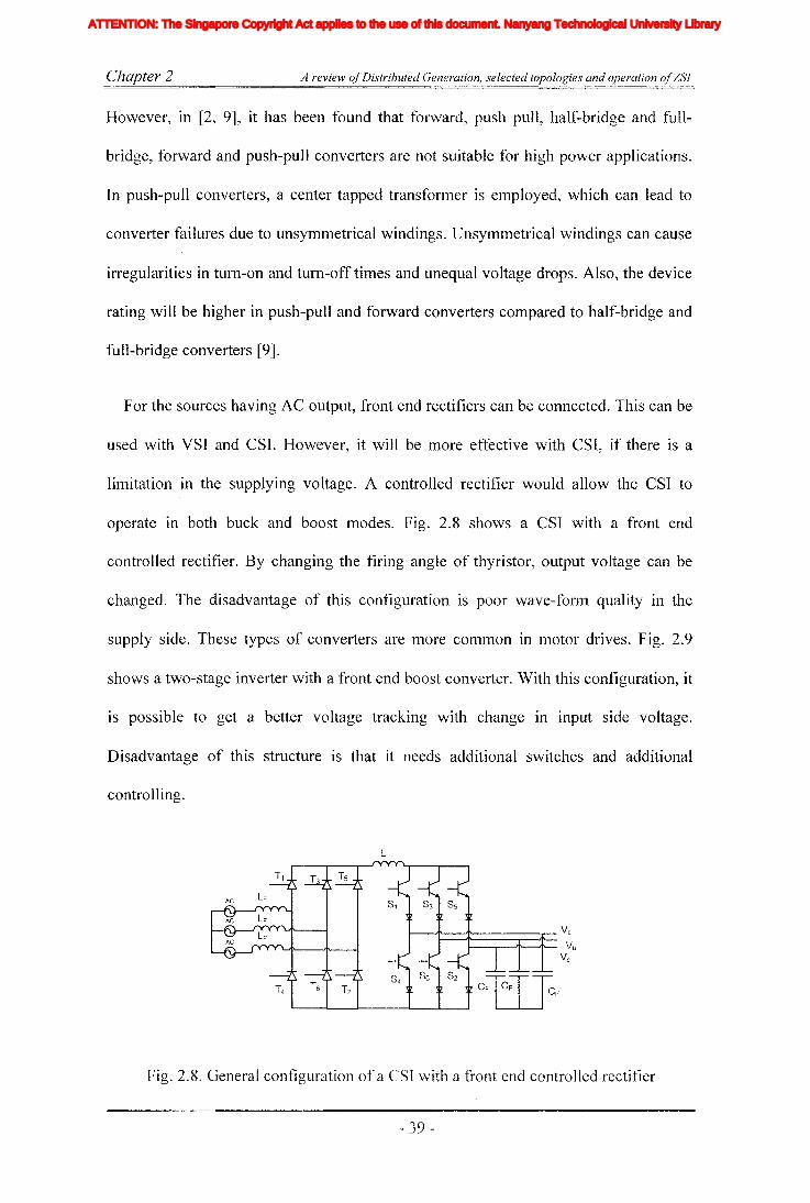
Chapter 2 A review ofDistributed Generation, selected topologies and operation ofZSl
However, in [2, 9], it has been found that forward, push pull, half-bridge and full-
bridge, forward and push-pull converters are not suitable for high power applications.
In push-pull converters, a center tapped transformer is employed, which can lead to
converter failures due to unsymmetrical windings. Unsymmetrical windings can cause
irregularities in turn-on and tum-off times and unequal voltage drops. Also, the device
rating will be higher in push-pull and forward converters compared to half-bridge and
full-bridge converters [9].
For the sources having AC output, front end rectifiers can be connected. This can be
used with VSI and CSI. However, it will be more effective with CSI, if there is a
limitation in the supplying voltage. A controlled rectifier would allow the CSI to
operate in both buck and boost modes. Fig. 2.8 shows a CSI with a front end
controlled rectifier. By changing the firing angle of thyristor, output voltage can be
changed. The disadvantage of this configuration is poor wave-fonn quality in the
supply side. These types of converters are more common in motor drives. Fig. 2.9
shows a two-stage inverter with a front end boost converter. With this configuration, it
is possible to get a better voltage tracking with change in input side voltage.
Disadvantage of this structure is that it needs additional switches and additional
controlling.
L
t---.IJ'--~----.-- Va1---...---'1''----'1''-- Vb
Vc
Fig. 2.8. General configuration of a CST with a front end controlled rectifier
- 39 -
Iiq
Iod
Ioq
I odq
I max
1,Ie, Ici,Ic2IDC
IL_m
I MPP
IpvI scITHD
IzI Zn
lap*lap
Ia,Ip,IoIa *, Ip*,10*
Iah,Iphlin
12n
I;
afJ axis currentafJ axis reference currentafJO axis current componentsafJO axis reference current componentsafJ axis harmonic current componentsNeutral current of inverter 1Neutral current of inverter 2Zero sequence reference current
Average Z-source inductor currentPerturbed Z-source inductor current
Perturbed load currentConstantGain factor of fifth harmonics filterGain factor of seventh harmonics filterGain factor of eleventh harmonics filterDC side controller proportional gain of PI controllerDC side controller integral gain of PI controllerGain of the inverterIntegral gain of PI controller in current controllerGain of the hth resonance filterProportional gain of AC side inner loop controllerProportional gain of PI controller in current controllerProportional gain of zero sequence resonance controllerIntegral gain of the resonance controllerIntegral gain of the zero sequence resonance controllerIntegral gain of the hth resonance controllerProportional gain of AC side PI controllerIntegral gain of the AC side PI controllerMultiplying factor for harmonics eliminationDC side filter inductanceLoad inductanceNeutral inductanceGrid inductanceLeakage inductance of transformer
XVII
ATTENTION: The Singapore Copyright Act applies to the use of this document. Nanyang Technological University Library
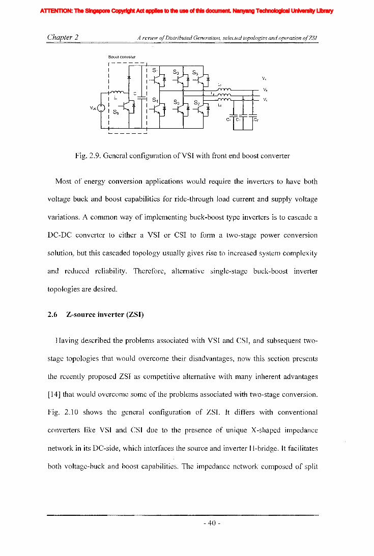
Chapter 2
Boost conveter
A review ofDistributed Generation, selected topologies and operation ofZSI
Fig. 2.9. General configuration ofVSI with front end boost converter
Most of energy conversion applications would require the inverters to have both
voltage buck and boost capabilities for ride-through load current and supply voltage
variations. A common way of implementing buck-boost type inverters is to cascade a
DC-DC converter to either a VSI or CSI to form a two-stage power conversion
solution, but this cascaded topology usually gives rise to increased system complexity
and reduced reliability. Therefore, alternative single-stage buck-boost inverter
topologies are desired.
2.6 Z-sonrce inverter (ZSI)
Having described the problems associated with VSI and CSI, and subsequent two
stage topologies that would overcome their disadvantages, now this section presents
the recently proposed ZSI as competitive alternative with many inherent advantages
[14] that would overcome some of the problems associated with two-stage conversion.
Fig. 2.10 shows the general configuration of ZSI. It differs with conventional
converters like VSI and CSI due to the presence of unique X-shaped impedance
network in its DC-side, which interfaces the source and inverter H-bridge. It facilitates
both voltage-buck and boost capabilities. The impedance network composed of split
- 40-
Iiq
Iod
Ioq
I odq
I max
1,Ie, Ici,Ic2IDC
IL_m
I MPP
IpvI scITHD
IzI Zn
lap*lap
Ia,Ip,IoIa *, Ip*,10*
Iah,Iphlin
12n
I;
afJ axis currentafJ axis reference currentafJO axis current componentsafJO axis reference current componentsafJ axis harmonic current componentsNeutral current of inverter 1Neutral current of inverter 2Zero sequence reference current
Average Z-source inductor currentPerturbed Z-source inductor current
Perturbed load currentConstantGain factor of fifth harmonics filterGain factor of seventh harmonics filterGain factor of eleventh harmonics filterDC side controller proportional gain of PI controllerDC side controller integral gain of PI controllerGain of the inverterIntegral gain of PI controller in current controllerGain of the hth resonance filterProportional gain of AC side inner loop controllerProportional gain of PI controller in current controllerProportional gain of zero sequence resonance controllerIntegral gain of the resonance controllerIntegral gain of the zero sequence resonance controllerIntegral gain of the hth resonance controllerProportional gain of AC side PI controllerIntegral gain of the AC side PI controllerMultiplying factor for harmonics eliminationDC side filter inductanceLoad inductanceNeutral inductanceGrid inductanceLeakage inductance of transformer
XVII
ATTENTION: The Singapore Copyright Act applies to the use of this document. Nanyang Technological University Library

Chapter 2 A review ojDistributed Generation, selected topologies and operation ojZSl
inductors and two capacitors. The supply can be a DC voltage source or a DC current
source or an AC source.
ZSI can take the form of current source type or voltage source type with small
structural change. Fig. 2.11 shows a voltage type ZSI, which facilitates voltage boost
capability avoiding the need of dead time. As such it simplifies the modulator as
typical VSI modulator requires additional circuits to insert the dead time. A series
diode is connected between source and impedance network, which protect the source
from a possible reverse current flow and also help the ZSI in boosting the voltage.
L1
Va
Voltage orVoltage or C2 Current Source
Vbcurrent source Inverter
TopologyVc
L2
Fig. 2.10. General block diagram representation of ZSI
~---r- Va
'--....,..--'1'- Vb
Fig. 2.11. Equivalent circuit representation of voltage-type ZSI
Fig. 2.12 shows current type ZSI. It facilitates current boosting while bucking the
voltage. That is, with this configuration it is possible to have lower voltage than the
supply with a current source, which cannot be achieved in conventional current source.
Additionally, need of avoiding open circuit would not arise, and this reduces the
protection requirements in modulation. A parallel diode is connected to the current
- 41 -
Iiq
Iod
Ioq
I odq
I max
1,Ie, Ici,Ic2IDC
IL_m
I MPP
IpvI scITHD
IzI Zn
lap*lap
Ia,Ip,IoIa *, Ip*,10*
Iah,Iphlin
12n
I;
afJ axis currentafJ axis reference currentafJO axis current componentsafJO axis reference current componentsafJ axis harmonic current componentsNeutral current of inverter 1Neutral current of inverter 2Zero sequence reference current
Average Z-source inductor currentPerturbed Z-source inductor current
Perturbed load currentConstantGain factor of fifth harmonics filterGain factor of seventh harmonics filterGain factor of eleventh harmonics filterDC side controller proportional gain of PI controllerDC side controller integral gain of PI controllerGain of the inverterIntegral gain of PI controller in current controllerGain of the hth resonance filterProportional gain of AC side inner loop controllerProportional gain of PI controller in current controllerProportional gain of zero sequence resonance controllerIntegral gain of the resonance controllerIntegral gain of the zero sequence resonance controllerIntegral gain of the hth resonance controllerProportional gain of AC side PI controllerIntegral gain of the AC side PI controllerMultiplying factor for harmonics eliminationDC side filter inductanceLoad inductanceNeutral inductanceGrid inductanceLeakage inductance of transformer
XVII
ATTENTION: The Singapore Copyright Act applies to the use of this document. Nanyang Technological University Library

Chapter 2 A review ofDistributed Generation, selected topologies and operation ofZSI
sources to facilitate freewheeling of inductor current if the open circuit state present in
the inverter. Steady-state analysis of this impedance network and the open-loop pulse-
width modulation of ZSI have already been described in [14, 51], which explicitly
show how the inverter achieves voltage-buck and boost. For the sake of completeness
these will be presented in detail in the next section.
L
VaIDe II~=+========::;:::::+= V
hVc
Fig. 2.12. Equivalent circuit representation of current type ZSI
2.6.1 Research and developments with Z-source inverters
Ever since Z-source inverter is introduced in 2003 [14], many researchers have
contributed in numerous aspects· of research on developing Z-source inverter and they
have published over one hundred papers in IEEE and other recognized journals and
conferences. Originally, this topology is proposed for fuel cell systems that are used in
hybrid electrical vehicles where fuel cells are known for their large variation in
operating voltage. Since then it has been found applications in variable speed drives,
distributed generation etc. Mainly, research work can be divided into research on
traditional ZSI and its modeling, analysis of operating modes, modulation design,
design of controllers and application development. Subsequently, structural
improvements and other topological variations based on ZSI to overcome some
linlitations in operation and improve the performance have been developed. Few
researchers have analyzed the operation of Z-source inverter [14, 5]], slnall signal
- 42 -
Iiq
Iod
Ioq
I odq
I max
1,Ie, Ici,Ic2IDC
IL_m
I MPP
IpvI scITHD
IzI Zn
lap*lap
Ia,Ip,IoIa *, Ip*,10*
Iah,Iphlin
12n
I;
afJ axis currentafJ axis reference currentafJO axis current componentsafJO axis reference current componentsafJ axis harmonic current componentsNeutral current of inverter 1Neutral current of inverter 2Zero sequence reference current
Average Z-source inductor currentPerturbed Z-source inductor current
Perturbed load currentConstantGain factor of fifth harmonics filterGain factor of seventh harmonics filterGain factor of eleventh harmonics filterDC side controller proportional gain of PI controllerDC side controller integral gain of PI controllerGain of the inverterIntegral gain of PI controller in current controllerGain of the hth resonance filterProportional gain of AC side inner loop controllerProportional gain of PI controller in current controllerProportional gain of zero sequence resonance controllerIntegral gain of the resonance controllerIntegral gain of the zero sequence resonance controllerIntegral gain of the hth resonance controllerProportional gain of AC side PI controllerIntegral gain of the AC side PI controllerMultiplying factor for harmonics eliminationDC side filter inductanceLoad inductanceNeutral inductanceGrid inductanceLeakage inductance of transformer
XVII
ATTENTION: The Singapore Copyright Act applies to the use of this document. Nanyang Technological University Library

Chapter 2 A review ofDistributed Generation, selected topologies and operation ofZSI
analysis [59], steady state analysis, operating modes and these are among some
popular topics that have been addressed in depth in last few years. Comprehensive
analysis on steady state analysis and operational principle of ZSI are described in the
original Z-source paper it self. Mainly, three operating states are introduced, namely,
null, active and shoot-through. All these three states are acceptable and required in the
proper operation of Z-source inverter. Active and null states are similar to that of
traditional VSI but shoot-through is inserted inside the null interval and the current is
limited when short-circuiting the inverter due to the presence of inductance in the
impedance network. However, similar to other popular DC-DC converters, Z-source
inverter also has discontinuous operation modes (DCM). It has been found that, there
are three additional states could be possible and they result from the discontinuity of
the original null, active and shoot-through states [60, 61]. These additional states result
from small inductance or low power factor operation. However, for correct function of
ZSI, these states should be avoided and the presence of them could result in incorrect
volt-second balance and decrease in waveform quality. It has been reported that with
added changes in structure of ZSI, this undesirable operating modes can be prevented.
One way is to replace the diode of ZSI with diode plus anti-parallel IGBT or a switch
[62], other possibility would be to have higher inductance and preventing the low
power factor operation. Modulation method development also has gained interest of
many researchers, a simple modulation method has been proposed in the first ZSI
paper. However, this method has increased number of switchings per half carrier cycle
compared to traditional VSI. This could result in increased losses. This problem is
solved in subsequent paper that proposed a carrier based PWM method [51] where six
individual reference signals are used to drive the switches in the three phase inverter
with shoot-through periods are inserted by shifting the top and bottom reference
- 43 -
Iiq
Iod
Ioq
I odq
I max
1,Ie, Ici,Ic2IDC
IL_m
I MPP
IpvI scITHD
IzI Zn
lap*lap
Ia,Ip,IoIa *, Ip*,10*
Iah,Iphlin
12n
I;
afJ axis currentafJ axis reference currentafJO axis current componentsafJO axis reference current componentsafJ axis harmonic current componentsNeutral current of inverter 1Neutral current of inverter 2Zero sequence reference current
Average Z-source inductor currentPerturbed Z-source inductor current
Perturbed load currentConstantGain factor of fifth harmonics filterGain factor of seventh harmonics filterGain factor of eleventh harmonics filterDC side controller proportional gain of PI controllerDC side controller integral gain of PI controllerGain of the inverterIntegral gain of PI controller in current controllerGain of the hth resonance filterProportional gain of AC side inner loop controllerProportional gain of PI controller in current controllerProportional gain of zero sequence resonance controllerIntegral gain of the resonance controllerIntegral gain of the zero sequence resonance controllerIntegral gain of the hth resonance controllerProportional gain of AC side PI controllerIntegral gain of the AC side PI controllerMultiplying factor for harmonics eliminationDC side filter inductanceLoad inductanceNeutral inductanceGrid inductanceLeakage inductance of transformer
XVII
ATTENTION: The Singapore Copyright Act applies to the use of this document. Nanyang Technological University Library

Chapter 2 A review ofDistributed Generation, selected topologies and operation ofZSJ
signals for each top and bottom arms respectively. This shifting creates an overlapping
period in top and bottom switching signals where they both will be in ON state. This
method is described in detail in the section 2.6.3. Subsequently, another variation of
PWM that has a maximum shoot-through [63] occupying whole null interval has been
proposed and is found to be having poor transient response. Then space vector based
modulation method has also been proposed [64] where shoot-through is equally spread
with reduced switching similar to the method proposed in [51] .
Small signal analysis and dynamic study on ZSI is first carried out by the author and
has been published in reference [59] and also presented in this thesis. Further studies
has been done with inductive and resistive loads in the AC sides [65]. Closed loop
controllers for ZSI has been first proposed in [17]. However, it has not emphasized the
dynamics of ZSI. In the 4th chapter of this thesis, a comprehensive analysis and multi
loop controller design for ZSI are presented which has been previously published in
[18]. Closed loop controllers are designed by modeling the ZSI which consists of two
subsystems and controlled in multi-loop manner. This has been extended in reference
[66] with direct control of output voltage of ZSI where a special filter network has
been proposed that measures the pulsating output voltage and directly controls it
without using capacitor voltage measurement to predict it as proposed in [66] .
Another important research area of ZSI is determining the topological variations of
ZSI converters. Voltage type ZSI has unidirectional power flow due to the presence of
diode between energy source and impedance network. It can be made bidirectional by
connecting an anti-parallel switch [62] across the diode. However, this complicates the
controlling as the switch requires a control signal and it has increased losses. Another
topological variation of Z-source is the rectifier designed based on the ZSI, where this
- 44-
Iiq
Iod
Ioq
I odq
I max
1,Ie, Ici,Ic2IDC
IL_m
I MPP
IpvI scITHD
IzI Zn
lap*lap
Ia,Ip,IoIa *, Ip*,10*
Iah,Iphlin
12n
I;
afJ axis currentafJ axis reference currentafJO axis current componentsafJO axis reference current componentsafJ axis harmonic current componentsNeutral current of inverter 1Neutral current of inverter 2Zero sequence reference current
Average Z-source inductor currentPerturbed Z-source inductor current
Perturbed load currentConstantGain factor of fifth harmonics filterGain factor of seventh harmonics filterGain factor of eleventh harmonics filterDC side controller proportional gain of PI controllerDC side controller integral gain of PI controllerGain of the inverterIntegral gain of PI controller in current controllerGain of the hth resonance filterProportional gain of AC side inner loop controllerProportional gain of PI controller in current controllerProportional gain of zero sequence resonance controllerIntegral gain of the resonance controllerIntegral gain of the zero sequence resonance controllerIntegral gain of the hth resonance controllerProportional gain of AC side PI controllerIntegral gain of the AC side PI controllerMultiplying factor for harmonics eliminationDC side filter inductanceLoad inductanceNeutral inductanceGrid inductanceLeakage inductance of transformer
XVII
ATTENTION: The Singapore Copyright Act applies to the use of this document. Nanyang Technological University Library

Chapter 2 A review ofDistributed Generation, selected topologies and operation ofZSJ
topology provides both buck and boost operations that is not possible with traditional
rectifiers [67]. Various multi-level topologies are also proposed based on ZSI. Multi
level type topological variations can be categorized into diode clamp and cascaded
types. First, neutral point clamped (NPC) three level ZSI is proposed in [68] which
uses two Z-source impedance networks. Therefore, this topology is not efficient.
Subsequently, the same authors have improved the NPC to operate with only single Z
source impedance network [69]. To date, multi level topologies have been improved to
operate with five levels [70]. Even though some researchers have developed matrix
converters and other AC to AC converter topologies based on ZSI, they are not within
the scope of this thesis. In addition, other topological variations based on ZSI are four
leg inverter, dual inverter, parallel inverter and series parallel inverter topologies.
These topologies would help to achieve different aspects of power quality. Another
interesting topological variation is the embedded source type topology where one
capacitor of Z-source impedance network is replaced with a battery bank and this
would improve the operation range and bidirectional operation [71, 72].
Z-source inverter has been developed for different applications. Variable speed
drives [73], hybrid electrical vehicles [74], and distributed generation applications
where fuel cell systems, solar cells, and wind systems have been proposed to be used
with ZSI [34, 40, 75-78]. This thesis will also focus on developing ZSI based DO
topologies for distributed power generation and power quality improvement. Before
moving to these aspects first consider the steady state analysis of ZSI and its
modulation methods.
- 45 -
Iiq
Iod
Ioq
I odq
I max
1,Ie, Ici,Ic2IDC
IL_m
I MPP
IpvI scITHD
IzI Zn
lap*lap
Ia,Ip,IoIa *, Ip*,10*
Iah,Iphlin
12n
I;
afJ axis currentafJ axis reference currentafJO axis current componentsafJO axis reference current componentsafJ axis harmonic current componentsNeutral current of inverter 1Neutral current of inverter 2Zero sequence reference current
Average Z-source inductor currentPerturbed Z-source inductor current
Perturbed load currentConstantGain factor of fifth harmonics filterGain factor of seventh harmonics filterGain factor of eleventh harmonics filterDC side controller proportional gain of PI controllerDC side controller integral gain of PI controllerGain of the inverterIntegral gain of PI controller in current controllerGain of the hth resonance filterProportional gain of AC side inner loop controllerProportional gain of PI controller in current controllerProportional gain of zero sequence resonance controllerIntegral gain of the resonance controllerIntegral gain of the zero sequence resonance controllerIntegral gain of the hth resonance controllerProportional gain of AC side PI controllerIntegral gain of the AC side PI controllerMultiplying factor for harmonics eliminationDC side filter inductanceLoad inductanceNeutral inductanceGrid inductanceLeakage inductance of transformer
XVII
ATTENTION: The Singapore Copyright Act applies to the use of this document. Nanyang Technological University Library

Chapter 2 A review ofDistributed Generation, selected topologies and operation ofZSI
2.6.2 Steady state analysis and operational principle
For describing ZSI principle of operation, consider Fig. 2.11, which shows
voltage type three phase ZSI. Traditional VSI has eight switching states, out of that six
are active states and the other two are null states. Whereas voltage type ZSI has nine
switching states, due to the presence of additional shoot-through state. In this state,
one or more legs of an inverter are short-circuited. This additional state facilitates the
boosting of the input voltage. However, with conventional inverters, short circuiting
has been avoided to protect the inverter switches [14, 51].
ZSI has three different states namely, null, active and shoot-through. As
described in the research and development of ZSI section, in addition to shoot through,
null and active states, there can be other discontinuous conduction modes (DCM)
could result from the main operating states. I-Iowever, they tend to impede the proper
operation of ZSI. Hence, DCM operation is not considered in the context of this thesis.
Null and active states can be represented in the same equivalent circuit for steady state
analysis and this common state is named as non-shoot-through state. The equivalent
circuit is given in Fig. 2.13. Fig. 2.14 shows the equivalent circuit diagram for shoot
through state~ For the simplicity of steady state analysis, inductors and capacitors are
assumed to be ideal. The inverter action is replaced by a current source plus single
switch. For the simplicity of analysis, equal inductance and capacitance values are
assumed. Then the network becomes symmetrical hence; Vel = Vc:2 = Vc: and
- 46-
Iiq
Iod
Ioq
I odq
I max
1,Ie, Ici,Ic2IDC
IL_m
I MPP
IpvI scITHD
IzI Zn
lap*lap
Ia,Ip,IoIa *, Ip*,10*
Iah,Iphlin
12n
I;
afJ axis currentafJ axis reference currentafJO axis current componentsafJO axis reference current componentsafJ axis harmonic current componentsNeutral current of inverter 1Neutral current of inverter 2Zero sequence reference current
Average Z-source inductor currentPerturbed Z-source inductor current
Perturbed load currentConstantGain factor of fifth harmonics filterGain factor of seventh harmonics filterGain factor of eleventh harmonics filterDC side controller proportional gain of PI controllerDC side controller integral gain of PI controllerGain of the inverterIntegral gain of PI controller in current controllerGain of the hth resonance filterProportional gain of AC side inner loop controllerProportional gain of PI controller in current controllerProportional gain of zero sequence resonance controllerIntegral gain of the resonance controllerIntegral gain of the zero sequence resonance controllerIntegral gain of the hth resonance controllerProportional gain of AC side PI controllerIntegral gain of the AC side PI controllerMultiplying factor for harmonics eliminationDC side filter inductanceLoad inductanceNeutral inductanceGrid inductanceLeakage inductance of transformer
XVII
ATTENTION: The Singapore Copyright Act applies to the use of this document. Nanyang Technological University Library

Chapter 2 A review ofDistributed Generation, selected topologies and operation ofZSJ
1tl1...--L1
Vd IC2 IC1
ve,lV s
jllOOdVC2t Cz C1Seq
+
Lz
IL2----..
\.1..2
Fig. 2.13. Simplified equivalent representations of Z-source impedance network
IL2 --..VL2
Fig. 2.14. Equivalent circuit of Z-source impedance network in shoot-through state
For the non- shoot-through state, steady state equation can be obtained as in (2-3).
(2-3)
From the Fig. 2.14, where Z-source is in shoot-through state the following equations
can be obtained.
(2-4)
- 47 -
Iiq
Iod
Ioq
I odq
I max
1,Ie, Ici,Ic2IDC
IL_m
I MPP
IpvI scITHD
IzI Zn
lap*lap
Ia,Ip,IoIa *, Ip*,10*
Iah,Iphlin
12n
I;
afJ axis currentafJ axis reference currentafJO axis current componentsafJO axis reference current componentsafJ axis harmonic current componentsNeutral current of inverter 1Neutral current of inverter 2Zero sequence reference current
Average Z-source inductor currentPerturbed Z-source inductor current
Perturbed load currentConstantGain factor of fifth harmonics filterGain factor of seventh harmonics filterGain factor of eleventh harmonics filterDC side controller proportional gain of PI controllerDC side controller integral gain of PI controllerGain of the inverterIntegral gain of PI controller in current controllerGain of the hth resonance filterProportional gain of AC side inner loop controllerProportional gain of PI controller in current controllerProportional gain of zero sequence resonance controllerIntegral gain of the resonance controllerIntegral gain of the zero sequence resonance controllerIntegral gain of the hth resonance controllerProportional gain of AC side PI controllerIntegral gain of the AC side PI controllerMultiplying factor for harmonics eliminationDC side filter inductanceLoad inductanceNeutral inductanceGrid inductanceLeakage inductance of transformer
XVII
ATTENTION: The Singapore Copyright Act applies to the use of this document. Nanyang Technological University Library

Chapter 2 A review ojDistributed Generation, selected topologies and operation ojZSJ
The total duration of non- shoot-through time and total shoot-through time are denoted
by Tj and To then T = T]+Tois period of the carrier signal. Then consider the average
voltage across the inductor, which should sum up to zero and from (2-3) and (2-4);
(2-5)
Then from above equations peak voltage across the inverter Vs and peak AC output
voltage Vx can be obtained as follows.
17 = 1 Vs 1-2Ta/T DC
V =M vsx 2
Where M is the modulation index
(2-6)
(2-7)
Define B = 1 , boost factor in the DC-side then peak AC-side can be written as:1-2To/T
(2-8)
Similarly, if the DC source is a current source, AC-side peak current Ix can be derived
as follows
(2-9)
From equation 2-8 it is possible to note that by changing modulation index while
keeping the boost factor at one, it is possible to operate the Z-source inverter in buck
operating mode. Then from 2-6 and 2-7, by changing the To output voltage of
impedance network can be boosted to have B> 1. Then by selecting a suitable M, the
output voltage can have a larger value than the input voltage. However, one can find
different values for shoot through and modulation index to get a particular voltage
gain. Therefore, careful consideration is needed when designing controllers.
- 48 -
Iiq
Iod
Ioq
I odq
I max
1,Ie, Ici,Ic2IDC
IL_m
I MPP
IpvI scITHD
IzI Zn
lap*lap
Ia,Ip,IoIa *, Ip*,10*
Iah,Iphlin
12n
I;
afJ axis currentafJ axis reference currentafJO axis current componentsafJO axis reference current componentsafJ axis harmonic current componentsNeutral current of inverter 1Neutral current of inverter 2Zero sequence reference current
Average Z-source inductor currentPerturbed Z-source inductor current
Perturbed load currentConstantGain factor of fifth harmonics filterGain factor of seventh harmonics filterGain factor of eleventh harmonics filterDC side controller proportional gain of PI controllerDC side controller integral gain of PI controllerGain of the inverterIntegral gain of PI controller in current controllerGain of the hth resonance filterProportional gain of AC side inner loop controllerProportional gain of PI controller in current controllerProportional gain of zero sequence resonance controllerIntegral gain of the resonance controllerIntegral gain of the zero sequence resonance controllerIntegral gain of the hth resonance controllerProportional gain of AC side PI controllerIntegral gain of the AC side PI controllerMultiplying factor for harmonics eliminationDC side filter inductanceLoad inductanceNeutral inductanceGrid inductanceLeakage inductance of transformer
XVII
ATTENTION: The Singapore Copyright Act applies to the use of this document. Nanyang Technological University Library

Chapter 2 A review ofDistributed Generation, selected topologies and operation ojZSI
2.6.3 Modulation methods for ZSI
Having studied the operating principle of the ZSI, this section now presents some of
the popularly adopted modulation methods for voltage type ZSI. As described in the
previous section, the main difference of ZSI compared to the traditional inverter is the
presence of shoot-through state. The shoot-through state can be inserted anywhere in
the switching signal. However, the duration of active state should not be affected, that
is volt second average should not be changed. There are different modulation schemes
proposed in [14, 51, 60]. As described in the original paper on ZSI the simplest
modulation is to insert the shoot-through inside the traditional null interval. Fig.
2.15(a) shows the modulation diagram for simple shoot-through method where the
shoot-through references are derived by comparing the carrier signal with a constant
reference signal. As indicated in Fig. 2.15(a), two references are derived from required
shoot-through, (1-Ds) and (Ds -1). Now the derived shoot-through signals have to be
inserted inside the traditional modulation signals of the VSI by comparing the
reference signal and the carrier. In order to insert the shoot-through, both switches of
an inverter arm should be switched on. There are few possible ways of inserting the
shoot-through, when the shoot-through signal is one and if all the switches top
switches of the inverter (8 1,83 and 85) are off that is if the inverter is in 000 state, one
or more the top switches have to be switched on. Similarly, when the inverter goes to
III state (all the switches top switches S1, 83 and 85 are on) one or more of the bottom
switches have to be switched on. However, switching-on of all the switches is needless
and if the shoot-through allocated only in a particular arm then it would be stressed.
However, this method has a disadvantage due to the increased number of switching
transitions per half s carrier cycle. To avoid that another PWM method has been
- 49-
Iiq
Iod
Ioq
I odq
I max
1,Ie, Ici,Ic2IDC
IL_m
I MPP
IpvI scITHD
IzI Zn
lap*lap
Ia,Ip,IoIa *, Ip*,10*
Iah,Iphlin
12n
I;
afJ axis currentafJ axis reference currentafJO axis current componentsafJO axis reference current componentsafJ axis harmonic current componentsNeutral current of inverter 1Neutral current of inverter 2Zero sequence reference current
Average Z-source inductor currentPerturbed Z-source inductor current
Perturbed load currentConstantGain factor of fifth harmonics filterGain factor of seventh harmonics filterGain factor of eleventh harmonics filterDC side controller proportional gain of PI controllerDC side controller integral gain of PI controllerGain of the inverterIntegral gain of PI controller in current controllerGain of the hth resonance filterProportional gain of AC side inner loop controllerProportional gain of PI controller in current controllerProportional gain of zero sequence resonance controllerIntegral gain of the resonance controllerIntegral gain of the zero sequence resonance controllerIntegral gain of the hth resonance controllerProportional gain of AC side PI controllerIntegral gain of the AC side PI controllerMultiplying factor for harmonics eliminationDC side filter inductanceLoad inductanceNeutral inductanceGrid inductanceLeakage inductance of transformer
XVII
ATTENTION: The Singapore Copyright Act applies to the use of this document. Nanyang Technological University Library

Chapter 2 A review ofDistributed Generation, selected topologies and operation ofZSJ
proposed in [51], where it uses six sine waves instead of three in normal VSI, as
shown in Fig. 2.15(b).
Here two sine waves are used to generate switching signals for each arm and two
sine waves shifted up or down to get the required shoot-through level. This results in
equally spread six shoot-through intervals per half carrier cycle. The shoot-through
signals are inserted without increasing the number of switchings per half carrier cycle.
Also by mixing with third harmonic signal, the modulation method can be further
improved to use the boosted voltage effectively. Furthermore, this spread shoot-
through insertion method would result in improved spectral characteristics. [51]. Third
method, named as maximum boost modulation scheme, in which shoot-through
accommodates the whole null interval. This method is similar to the simple shoot-
through method where shoot-through is only accommodated in traditional null interval
and even then number of switching per half carrier cycle is reduced. But this
modulation method would result in poor dynamic response [79].
1000 I 100 I 110 I 111 I 1111 I 110 I 100 I000 I'\ Sh~ot-throughitate ~ ~
. . .• & • . '. •••
~ ~ ~ ~ \ ~ ··\·······~········~·~ke~:~~!:!~~~~~·~··+······: ~
~ :. Ref. v :CD
~. : Ref. Vc .
.~ .:: :.::: Ref. Shoot-through·25 ········c·······:-···········:-·················;········: : : : ~ .: : ;:J ::: :...: ..::
i~. · ~..~ S3 1-1----.---~__~_---I
S6 I
S5S2 ...-------,
-.....,....---'--~--~ t.... ----'
(a)
- 50 -
Iiq
Iod
Ioq
I odq
I max
1,Ie, Ici,Ic2IDC
IL_m
I MPP
IpvI scITHD
IzI Zn
lap*lap
Ia,Ip,IoIa *, Ip*,10*
Iah,Iphlin
12n
I;
afJ axis currentafJ axis reference currentafJO axis current componentsafJO axis reference current componentsafJ axis harmonic current componentsNeutral current of inverter 1Neutral current of inverter 2Zero sequence reference current
Average Z-source inductor currentPerturbed Z-source inductor current
Perturbed load currentConstantGain factor of fifth harmonics filterGain factor of seventh harmonics filterGain factor of eleventh harmonics filterDC side controller proportional gain of PI controllerDC side controller integral gain of PI controllerGain of the inverterIntegral gain of PI controller in current controllerGain of the hth resonance filterProportional gain of AC side inner loop controllerProportional gain of PI controller in current controllerProportional gain of zero sequence resonance controllerIntegral gain of the resonance controllerIntegral gain of the zero sequence resonance controllerIntegral gain of the hth resonance controllerProportional gain of AC side PI controllerIntegral gain of the AC side PI controllerMultiplying factor for harmonics eliminationDC side filter inductanceLoad inductanceNeutral inductanceGrid inductanceLeakage inductance of transformer
XVII
ATTENTION: The Singapore Copyright Act applies to the use of this document. Nanyang Technological University Library

Chapter 2 A review ofDistributed Generation, selected topologies and operation ofZSI
000 100 /I 11 0 II 111 111 II 110 II 100 II 000:, ::~~oot-th~~ugh ~tate.. .. ... .
:: Ref. Va
83 :1L----~--:__----'1:8 6 !: .. ..:,
85
~ :L-1 -...._""-----.-~!~ --~-_i_":-'~-
__--:-- --'8 2'---J1: : L-' _
..~ =====:::;==~'s;;;::'===*:~:==;::::=R=ef==:"V=b;;:::=:: ===7."~"==~:=::;::=0-
~ ====::::;:=="=.==~.~.===:=Re=f.=Vc~::====.="==:=:==>
oSOJ "
~ 8 1 : : !'-----..,...,.__---.,....,.._~....,......-~----:-,...---~_--II:
£~. :~N : -:
(b)
Fig. 2.15 Modulation signals for ZSI (a) Silnple shoot-through method
(b) Minimum switching shoot-through method
2.7 Discussion
This chapter has introduced the distributed generation concept and its importance in
tomorrow's power system. Subsequently, some of important energy sources, storage
units that are commonly used with DG are introduced. Common power quality issues
that could arise in power distribution network and commonly used power electronic
solutions that are used to rectify some of these power quality problems are discussed.
Interfacing converter topologies that are used to integrate mentioned DG sources and
storages are discussed with emphasis given to identify their limitations in integrating
the renewable sources and how those limitations are overcome. As introduction on
recently proposed ZSI is also given. Operational principle and modulation methods are
presented to enable the readers' easy understanding of the subsequent chapters.
- 51 -
Iiq
Iod
Ioq
I odq
I max
1,Ie, Ici,Ic2IDC
IL_m
I MPP
IpvI scITHD
IzI Zn
lap*lap
Ia,Ip,IoIa *, Ip*,10*
Iah,Iphlin
12n
I;
afJ axis currentafJ axis reference currentafJO axis current componentsafJO axis reference current componentsafJ axis harmonic current componentsNeutral current of inverter 1Neutral current of inverter 2Zero sequence reference current
Average Z-source inductor currentPerturbed Z-source inductor current
Perturbed load currentConstantGain factor of fifth harmonics filterGain factor of seventh harmonics filterGain factor of eleventh harmonics filterDC side controller proportional gain of PI controllerDC side controller integral gain of PI controllerGain of the inverterIntegral gain of PI controller in current controllerGain of the hth resonance filterProportional gain of AC side inner loop controllerProportional gain of PI controller in current controllerProportional gain of zero sequence resonance controllerIntegral gain of the resonance controllerIntegral gain of the zero sequence resonance controllerIntegral gain of the hth resonance controllerProportional gain of AC side PI controllerIntegral gain of the AC side PI controllerMultiplying factor for harmonics eliminationDC side filter inductanceLoad inductanceNeutral inductanceGrid inductanceLeakage inductance of transformer
XVII
ATTENTION: The Singapore Copyright Act applies to the use of this document. Nanyang Technological University Library

Chapter 3 Small-signal analysis and graphical Signal-Flow Analysis
Chapter 3
Small-signal analysis and graphical signal-flow
analysis
3.1 Introduction
Power inverters are increasingly used In modern energy converSIon systems,
including UPS, motor drives and active interfaces for localized and distributed
generation. Most of these applications would requIre the inverters to have both
voltage-buck and boost capabilities for riding through load current and supply voltage
variations. As described in chapter 2, a common way of implementing buck-boost
inverters is to cascade a DC-DC converter to either a buck VSI or boost CSI to form a
two-stage power conversion solution. But this cascaded topology usually gives rise to
increased system complexity and reduced reliability. As a cOinpetitive alternative ZSI
is proposed recently with many inherent advantages [14].
Steady-state analysis of this impedance network and the open-loop pulse-width
modulation of the ZSI have already been described in chapter 2 and [14, 51] to
explicitly show how the inverter achieves voltage-buck and boost. An obvious
extension to research on ZSI would be the development of closed-loop control
schemes, which will be presented in chapter 4 of this thesis. Before moving into
designing, it is best to understand the dynamics of the Z-source impedance network
where stability, disturbance rejection and dynamic response are of concern. These
issues can be studied theoretically by modeling the ZSI as a product of two transfer
functions, representing the inverter circuitry and Z-source impedance network.
- 52 -
Iiq
Iod
Ioq
I odq
I max
1,Ie, Ici,Ic2IDC
IL_m
I MPP
IpvI scITHD
IzI Zn
lap*lap
Ia,Ip,IoIa *, Ip*,10*
Iah,Iphlin
12n
I;
afJ axis currentafJ axis reference currentafJO axis current componentsafJO axis reference current componentsafJ axis harmonic current componentsNeutral current of inverter 1Neutral current of inverter 2Zero sequence reference current
Average Z-source inductor currentPerturbed Z-source inductor current
Perturbed load currentConstantGain factor of fifth harmonics filterGain factor of seventh harmonics filterGain factor of eleventh harmonics filterDC side controller proportional gain of PI controllerDC side controller integral gain of PI controllerGain of the inverterIntegral gain of PI controller in current controllerGain of the hth resonance filterProportional gain of AC side inner loop controllerProportional gain of PI controller in current controllerProportional gain of zero sequence resonance controllerIntegral gain of the resonance controllerIntegral gain of the zero sequence resonance controllerIntegral gain of the hth resonance controllerProportional gain of AC side PI controllerIntegral gain of the AC side PI controllerMultiplying factor for harmonics eliminationDC side filter inductanceLoad inductanceNeutral inductanceGrid inductanceLeakage inductance of transformer
XVII
ATTENTION: The Singapore Copyright Act applies to the use of this document. Nanyang Technological University Library
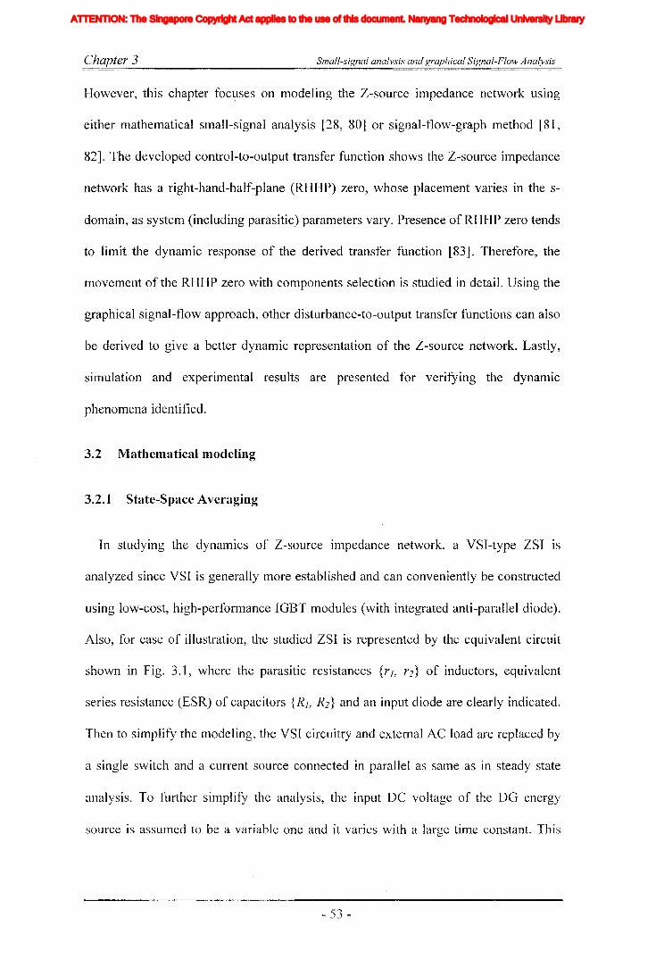
Chapter 3 Small-signal analysis and graphical Signal-Flow Analysis
However, this chapter focl:lses on modeling the Z-source impedance network using
either mathematical small-signal analysis [28, 80] or signal-flow-graph method [81,
82]. The developed control-to-output transfer function shows the Z-source impedance
network has a right-hand-half-plane (RHHP) zero, whose placement varies in the s
domain, as system (including parasitic) parameters vary. Presence of RHHP zero tends
to limit the dynamic response of the derived transfer function [83]. Therefore, the
movement of the RHHP zero with components selection is studied in detail. Using the
graphical signal-flow approach, other disturbance-to-output transfer functions can also
be derived to give a better dynamic representation of the Z-source network. Lastly,
simulation and experimental results are presented for verifying the dynamic
phenomena identified.
3.2 Mathematical modeling
3.2.1 State-Space Averaging
In studying the dynaluics of Z-source impedance network, a VSI-type ZSI is
analyzed since VSI is generally more established and can conveniently be constructed
using low-cost, high-performance IGBT modules (with integrated anti-parallel diode).
Also, for ease of illustration, the studied ZSI is represented by the equivalent circuit
shown in Fig. 3.1, where the parasitic resistances {rJ, r2} of inductors, equivalent
series resistance (ESR) of capacitors {R J, R2 } and an input diode are clearly indicated.
Then to simplify the modeling, the VSI circuitry and external AC load are replaced by
a single switch and a current source connected in parallel as same as in steady state
analysis. To further simplify the analysis, the input DC voltage of the DG energy
source is assumed to be a variable one and it varies with a large time constant. This
- 53 -
Iiq
Iod
Ioq
I odq
I max
1,Ie, Ici,Ic2IDC
IL_m
I MPP
IpvI scITHD
IzI Zn
lap*lap
Ia,Ip,IoIa *, Ip*,10*
Iah,Iphlin
12n
I;
afJ axis currentafJ axis reference currentafJO axis current componentsafJO axis reference current componentsafJ axis harmonic current componentsNeutral current of inverter 1Neutral current of inverter 2Zero sequence reference current
Average Z-source inductor currentPerturbed Z-source inductor current
Perturbed load currentConstantGain factor of fifth harmonics filterGain factor of seventh harmonics filterGain factor of eleventh harmonics filterDC side controller proportional gain of PI controllerDC side controller integral gain of PI controllerGain of the inverterIntegral gain of PI controller in current controllerGain of the hth resonance filterProportional gain of AC side inner loop controllerProportional gain of PI controller in current controllerProportional gain of zero sequence resonance controllerIntegral gain of the resonance controllerIntegral gain of the zero sequence resonance controllerIntegral gain of the hth resonance controllerProportional gain of AC side PI controllerIntegral gain of the AC side PI controllerMultiplying factor for harmonics eliminationDC side filter inductanceLoad inductanceNeutral inductanceGrid inductanceLeakage inductance of transformer
XVII
ATTENTION: The Singapore Copyright Act applies to the use of this document. Nanyang Technological University Library
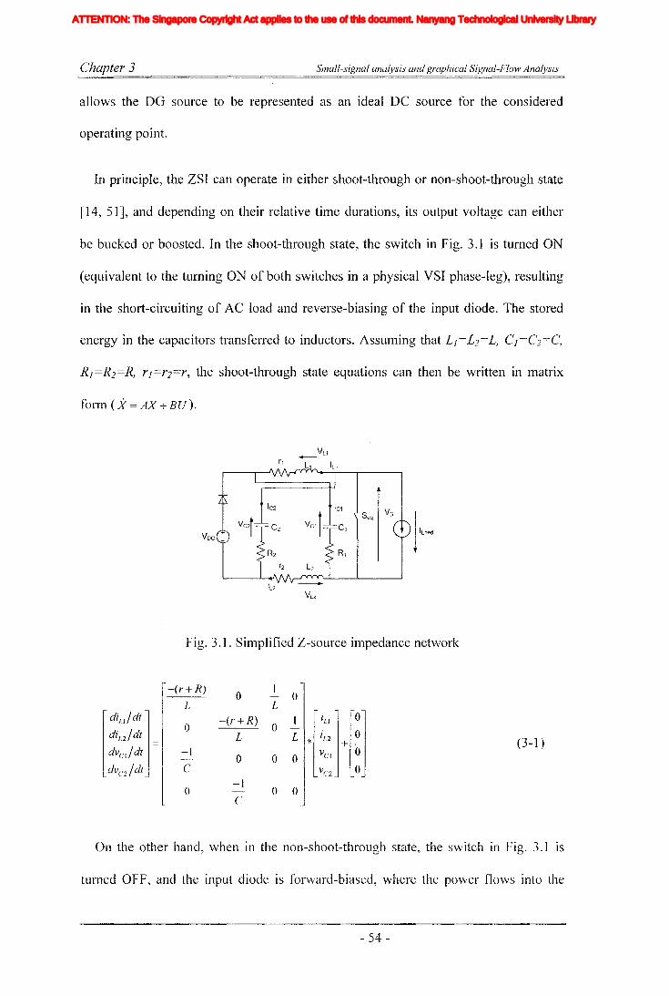
Chapter 3 Small-signal analysis and graphical Signal-Flow Analysis
allows the DO source to be represented as an ideal DC source for the considered
operating point.
In principle, the ZSI can operate in either shoot-through or non-shoat-through state
[14, 51], and depending on their relative time durations, its output voltage can either
be bucked or boosted. In the shoot-through state, the switch in Fig. 3.1 is turned ON
(equivalent to the turning ON of both switches in a physical VSI phase-leg), resulting
in the short-circuiting of AC load and reverse-biasing of the input diode. The stored
energy in the capacitors transferred to inductors. Assuming that LJ=L2=L, CJ=C2=C,
R j =R2=R, r]=r2=r, the shoot-through state equations can then be written in matrix
form (X = AX + BU).
Fig. 3.1. Simplified Z-source impedance network
-(r+R)0
10-
L L
diLl / dt j -(r+R) 1 liLl jlOj0 0 -diL2 /dt L L * iL2 0 (3-1)dvcl/dt = -1 ::~ + ~- 0 0 0dvcz/dt C
0-1
0 0-C
On the other hand, when in the non-shoat-through state, the switch in Fig. 3.1 is
turned OFF, and the input diode is forward-biased, where the power flows into the
- 54 -
Iiq
Iod
Ioq
I odq
I max
1,Ie, Ici,Ic2IDC
IL_m
I MPP
IpvI scITHD
IzI Zn
lap*lap
Ia,Ip,IoIa *, Ip*,10*
Iah,Iphlin
12n
I;
afJ axis currentafJ axis reference currentafJO axis current componentsafJO axis reference current componentsafJ axis harmonic current componentsNeutral current of inverter 1Neutral current of inverter 2Zero sequence reference current
Average Z-source inductor currentPerturbed Z-source inductor current
Perturbed load currentConstantGain factor of fifth harmonics filterGain factor of seventh harmonics filterGain factor of eleventh harmonics filterDC side controller proportional gain of PI controllerDC side controller integral gain of PI controllerGain of the inverterIntegral gain of PI controller in current controllerGain of the hth resonance filterProportional gain of AC side inner loop controllerProportional gain of PI controller in current controllerProportional gain of zero sequence resonance controllerIntegral gain of the resonance controllerIntegral gain of the zero sequence resonance controllerIntegral gain of the hth resonance controllerProportional gain of AC side PI controllerIntegral gain of the AC side PI controllerMultiplying factor for harmonics eliminationDC side filter inductanceLoad inductanceNeutral inductanceGrid inductanceLeakage inductance of transformer
XVII
ATTENTION: The Singapore Copyright Act applies to the use of this document. Nanyang Technological University Library
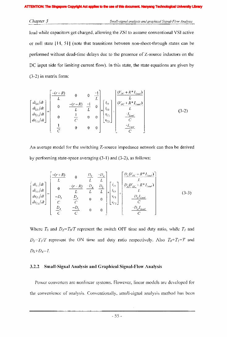
Chapter 3 Small-signal analysis and graphical Signal-Flow Analysis
load while capacitors get charged, allowing the ZSI to assume conventional VSI active
or null state [14, 51] (note that transitions between non-shoot-through states can be
performed without dead-time delays due to the presence of Z-source inductors on the
DC input side for limiting current flow). In this state, the state equations are given by
(3-2) in matrix form:
-(r+R)0 0
-1 (VDC + R *ILoad )-
L L L
[ diLl/dt1 -(r+R) -1
[iLl 1(VDC + R *ILoad )
0 - 0diLZ/dt _ L L * iLZ + L (3-2)dvCl/dt -
01
0 0VCI
- ILoad-
dVcz/dt C Vcz C
1 -I- 0 0 0 ~
C C
An average model for the switching Z-source impedance network can then be derived
by performing state-space averaging (3-1) and (3-2), as follows:
-(r+ R)0
Ds -DA DA (VDC + R *ILoad )
L L L L
[ diLl
/ dt1 -(r+R) -DA Ds
[in jDA(VDC + R *ILoad )
0diLz/dt L L L * iLZ + L (3-3)dvcl / dt - -Ds DA 0 0
VCl -DAILoad
dvcz/dt C C VC2 C
DA -Ds 0 0 -DAILoadC C C
Where To and DA=ToIT represent the switch OFF time and duty ratio, while T] and
Ds=T]/T represent the ON time and duty ratio respectively. Also To+T]=T and
3.2.2 Small-Signal Analysis and Graphical Signal-Flow Analysis
Power converters are nonlinear systelTIs. However, linear models are developed for
the convenience of analysis. Conventionally, small-signal analysis method has been
- 55 -
Iiq
Iod
Ioq
I odq
I max
1,Ie, Ici,Ic2IDC
IL_m
I MPP
IpvI scITHD
IzI Zn
lap*lap
Ia,Ip,IoIa *, Ip*,10*
Iah,Iphlin
12n
I;
afJ axis currentafJ axis reference currentafJO axis current componentsafJO axis reference current componentsafJ axis harmonic current componentsNeutral current of inverter 1Neutral current of inverter 2Zero sequence reference current
Average Z-source inductor currentPerturbed Z-source inductor current
Perturbed load currentConstantGain factor of fifth harmonics filterGain factor of seventh harmonics filterGain factor of eleventh harmonics filterDC side controller proportional gain of PI controllerDC side controller integral gain of PI controllerGain of the inverterIntegral gain of PI controller in current controllerGain of the hth resonance filterProportional gain of AC side inner loop controllerProportional gain of PI controller in current controllerProportional gain of zero sequence resonance controllerIntegral gain of the resonance controllerIntegral gain of the zero sequence resonance controllerIntegral gain of the hth resonance controllerProportional gain of AC side PI controllerIntegral gain of the AC side PI controllerMultiplying factor for harmonics eliminationDC side filter inductanceLoad inductanceNeutral inductanceGrid inductanceLeakage inductance of transformer
XVII
ATTENTION: The Singapore Copyright Act applies to the use of this document. Nanyang Technological University Library
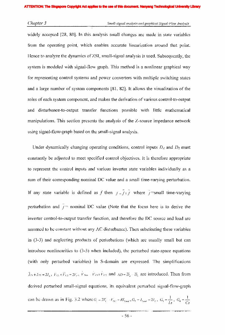
Chapter 3 Small-signal analysis and graphical Signal-Flow Analysis
widely accepted [28, 80]. In this analysis small changes are made in state variables
from the operating point, which enables accurate linearization around that point.
Hence to analyze the dynamics of ZSI, small-signal analysis is used. Subsequently, the
system is modeled with signal-flow graph. This method is a nonlinear graphical way
for representing control systems and power converters with multiple switching states
and a large number of system components [81, 82]. It allows the visualization of the
roles of each system component, and makes the derivation of various control-to-output
and disturbance-to-output transfer functions possible with little mathematical
manipulations. This section presents the analysis of the Z-source impedance network
using signal-flow-graph based on the small-signal analysis.
Under dynamically changing operating conditions, control inputs DA and Ds must
constantly be adjusted to meet specified control objectives. It is therefore appropriate
to represent the control inputs and various inverter state variables individually as a
sum of their corresponding nominal DC value and a small time-varying perturbation.
If any state variable is defined as f then f = f+; where ; =small time-varying
perturbation and f = nominal DC value (Note that the focus here is to derive the
inverter control-to-output transfer function, and therefore the DC source and load are
assumed to be constant without any AC disturbance). Then substituting these variables
in (3-3) and neglecting products of perturbations (which are usually small but can
introduce nonlinearities to (3-3) when included), the perturbed state-space equations
(with only perturbed variables) in S-domain are expressed. The simplifications
derived perturbed small-signal equations, its equivalent perturbed signal-flow-graph
1 1can be drawn as in Fig. 3.2 where G1 = 2~, - VDC - RILoad ' Gz = If-oad - 21r , G~ = -, G4 =-
.> Ls Cs
- 56-
Iiq
Iod
Ioq
I odq
I max
1,Ie, Ici,Ic2IDC
IL_m
I MPP
IpvI scITHD
IzI Zn
lap*lap
Ia,Ip,IoIa *, Ip*,10*
Iah,Iphlin
12n
I;
afJ axis currentafJ axis reference currentafJO axis current componentsafJO axis reference current componentsafJ axis harmonic current componentsNeutral current of inverter 1Neutral current of inverter 2Zero sequence reference current
Average Z-source inductor currentPerturbed Z-source inductor current
Perturbed load currentConstantGain factor of fifth harmonics filterGain factor of seventh harmonics filterGain factor of eleventh harmonics filterDC side controller proportional gain of PI controllerDC side controller integral gain of PI controllerGain of the inverterIntegral gain of PI controller in current controllerGain of the hth resonance filterProportional gain of AC side inner loop controllerProportional gain of PI controller in current controllerProportional gain of zero sequence resonance controllerIntegral gain of the resonance controllerIntegral gain of the zero sequence resonance controllerIntegral gain of the hth resonance controllerProportional gain of AC side PI controllerIntegral gain of the AC side PI controllerMultiplying factor for harmonics eliminationDC side filter inductanceLoad inductanceNeutral inductanceGrid inductanceLeakage inductance of transformer
XVII
ATTENTION: The Singapore Copyright Act applies to the use of this document. Nanyang Technological University Library

Chapter 3 Small-signal analysis and graphical Signal-Flow Analysis
and Gs = -(R + r). Moreover, VDC ' J Load and Ds represent input signal nodes or
disturbance sources while VSlInI
and JLoad represent output nodes. Unfortunately, Fig.
3.2 is difficult to solve due to the presence of numerous forward paths. However,
noting that the drawn signal-flow-graph is symmetrical along the horizontal axis with
assumed equal component values in both branches and the signal magnitudes at nodes
VCl and VC2 as well as at ILl and JL2 are equal, only the upper or lower half of Fig. 3.2
needs to be considered. The simplified signal-flow graph representation is redrawn in
Fig. 3.3 with an obvious reduction in the number of forward paths.
By applying Mason's gain rule, the required control-to-output and disturbance-to-
output transfer functions can then be derived. For an example, consider the derivation
of the control-to-output transfer function of VSlIlfl
to Ds, where the existence of two
closed-loops and two forward paths between the output and control signals (see Fig.
3.3) giving rise to the following transmittance equations:
(Where LA and LE are loop transmittances, PA and PE are path transmittances,
~A and ~B are cofactors of PA and PE, L\ is the graph determinant)
(3-4)
IS + (R + r)
Is
- 57 -
Iiq
Iod
Ioq
I odq
I max
1,Ie, Ici,Ic2IDC
IL_m
I MPP
IpvI scITHD
IzI Zn
lap*lap
Ia,Ip,IoIa *, Ip*,10*
Iah,Iphlin
12n
I;
afJ axis currentafJ axis reference currentafJO axis current componentsafJO axis reference current componentsafJ axis harmonic current componentsNeutral current of inverter 1Neutral current of inverter 2Zero sequence reference current
Average Z-source inductor currentPerturbed Z-source inductor current
Perturbed load currentConstantGain factor of fifth harmonics filterGain factor of seventh harmonics filterGain factor of eleventh harmonics filterDC side controller proportional gain of PI controllerDC side controller integral gain of PI controllerGain of the inverterIntegral gain of PI controller in current controllerGain of the hth resonance filterProportional gain of AC side inner loop controllerProportional gain of PI controller in current controllerProportional gain of zero sequence resonance controllerIntegral gain of the resonance controllerIntegral gain of the zero sequence resonance controllerIntegral gain of the hth resonance controllerProportional gain of AC side PI controllerIntegral gain of the AC side PI controllerMultiplying factor for harmonics eliminationDC side filter inductanceLoad inductanceNeutral inductanceGrid inductanceLeakage inductance of transformer
XVII
ATTENTION: The Singapore Copyright Act applies to the use of this document. Nanyang Technological University Library

Chapter 3
DA
I Load
Gs
Small-signal analysis and graphical Signal-Flow Analysis
Fig. 3.2. Graphical signal-flow representation of the Z-source impedance network.
Fig. 3.3. Simplified graphical signal-flow representation of the Z-source impedance
network.
Using (3-4) and Mason's fonnula (G(s) = L[\ *1;), the control-to-output transfer;}..
function VSUln
to Ds is then given by
VSum =2* {Ls(ILoad -2IL)}+{(r+R)*(ILoad -2IL)+MJ(2Vc -VDC -RiLoad )}
Ds LCs2 + (r + R)Cs + W 2
(3-5)
Similarly, other disturbance-to-output transfer functions of VSUln
to VDC ' P'>'1I1J1 to; road and
JIn to VDC can conveniently be derived as: Similarly, other disturbance-to-output
- 58 -
Iiq
Iod
Ioq
I odq
I max
1,Ie, Ici,Ic2IDC
IL_m
I MPP
IpvI scITHD
IzI Zn
lap*lap
Ia,Ip,IoIa *, Ip*,10*
Iah,Iphlin
12n
I;
afJ axis currentafJ axis reference currentafJO axis current componentsafJO axis reference current componentsafJ axis harmonic current componentsNeutral current of inverter 1Neutral current of inverter 2Zero sequence reference current
Average Z-source inductor currentPerturbed Z-source inductor current
Perturbed load currentConstantGain factor of fifth harmonics filterGain factor of seventh harmonics filterGain factor of eleventh harmonics filterDC side controller proportional gain of PI controllerDC side controller integral gain of PI controllerGain of the inverterIntegral gain of PI controller in current controllerGain of the hth resonance filterProportional gain of AC side inner loop controllerProportional gain of PI controller in current controllerProportional gain of zero sequence resonance controllerIntegral gain of the resonance controllerIntegral gain of the zero sequence resonance controllerIntegral gain of the hth resonance controllerProportional gain of AC side PI controllerIntegral gain of the AC side PI controllerMultiplying factor for harmonics eliminationDC side filter inductanceLoad inductanceNeutral inductanceGrid inductanceLeakage inductance of transformer
XVII
ATTENTION: The Singapore Copyright Act applies to the use of this document. Nanyang Technological University Library

Chapter 3 Small-signal analysis and graphical Signal-Flow Analysis
transfer functions of rlSllfll
to vDC , rlsllln to ILoad and Ds to riDe can conveniently be derived
as:
f7s'um - DA *I'1.D
vDC LCs 2 + (R + r)Cs + w 2
VslIm 2DA (Ls + R+ r - R * I1D)
ILoad
LCs 2 + (R + r )Cs + I1D 2
lIn (DA + i1D)Cs
-,JDe LCs2+(R+ r)Cs + MJ2
(3-6)
(3-7)
(3-8)
Although it may not be explicitly noticeable, it is possible to show the presence of a
RHHP zero by noting that during voltage-boosting:
• 21L
> 1Load
' implying that the first { } term in the numerator of (3-5) is negative,
• 75.5' < 0.5 and 15A = 1-15s ' implying that I1D > 0 [14, 51],
• {r,R} -)- 0, implying that (r + R)* (ILoad - 21L )« fill(2Vc - vDC - RILoad ) in the second { }
term in the numerator of (3-5),
• ~D > 0, 2Vc' > VDC and RILoad ~ 0, implying that the second { } term In the
numerator of (3-5) is positive.
Since the coefficient of s (first { }) and the constant (second { }) term in the
numerator are of opposite polarity, (3-5) has a RHHP zero gIven
by s:::: (r + R) * (II,oa" - 21£) + fill(2Vc - VDC - R1Loac/) , whose position in the s-dolnain vanesL(21/. - I/.oac!)
predolninantly with f...D.
- 59 -
Iiq
Iod
Ioq
I odq
I max
1,Ie, Ici,Ic2IDC
IL_m
I MPP
IpvI scITHD
IzI Zn
lap*lap
Ia,Ip,IoIa *, Ip*,10*
Iah,Iphlin
12n
I;
afJ axis currentafJ axis reference currentafJO axis current componentsafJO axis reference current componentsafJ axis harmonic current componentsNeutral current of inverter 1Neutral current of inverter 2Zero sequence reference current
Average Z-source inductor currentPerturbed Z-source inductor current
Perturbed load currentConstantGain factor of fifth harmonics filterGain factor of seventh harmonics filterGain factor of eleventh harmonics filterDC side controller proportional gain of PI controllerDC side controller integral gain of PI controllerGain of the inverterIntegral gain of PI controller in current controllerGain of the hth resonance filterProportional gain of AC side inner loop controllerProportional gain of PI controller in current controllerProportional gain of zero sequence resonance controllerIntegral gain of the resonance controllerIntegral gain of the zero sequence resonance controllerIntegral gain of the hth resonance controllerProportional gain of AC side PI controllerIntegral gain of the AC side PI controllerMultiplying factor for harmonics eliminationDC side filter inductanceLoad inductanceNeutral inductanceGrid inductanceLeakage inductance of transformer
XVII
ATTENTION: The Singapore Copyright Act applies to the use of this document. Nanyang Technological University Library
Chapter 3 Small-signal analysis and graphical Signal-Flow Analysis
3.3 Simulated time-domain and root locus analysis
In the previous section, the presence of RHHP zero in the impedance network is
realized through the state-space averaging and small-signal analysis. Such systems are
con1monly known as the non-minimum phase systems. The presence of RHHP zero
not only imposes limitations in controller design but also hinders the performance of
the system. In addition, RHHP zero is associated with inverse response, that is, for
given a control signal with expecting positive change in output, the output always goes
below the original value before rising up. Another thing is that, it limits the system
bandwidth as system poles tend to move towards RHHP zero. This would result in
poor system performance at high frequencies and at high gains [84]. This makes
considerable difficulties in obtaining the stability of the circuit and slower the system
performances. Also, the presence of changing parameters on the transfer function leads
to difficulties in designing a controller due to the movements in poles and zeros.
In this section, time domain and root locus plots obtained from MATLAB/Simulink
simulations using the system parameters given in Table 3-1 are presented (selected
capacitor values and inductor values are comparatively smaller than inductance and
capacitance needed for the similarly rated CSI and VSI). Notice from (3-5) that the
RHHP zero and pole locations in the s-domain move with Z-source parameters (r, R, L
and C) and control input Ds vary. For sources like fuel cells and photovoltaic cells,
that have wide operating ranges, it is ilnportant to study these zero and pole
movements in order to maintain acceptable perfonnance and stability. Towards this
end, various root loci are plotted in Fig. 3.4 by changing a selected parameter with the
others kept constant at values given in Table 3-1. In particular, Fig. 3.4 (a) shows the
shifting of polesl vertically towards the real axis and RFII-1P zero stays constant while
- 60 -
Iiq
Iod
Ioq
I odq
I max
1,Ie, Ici,Ic2IDC
IL_m
I MPP
IpvI scITHD
IzI Zn
lap*lap
Ia,Ip,IoIa *, Ip*,10*
Iah,Iphlin
12n
I;
afJ axis currentafJ axis reference currentafJO axis current componentsafJO axis reference current componentsafJ axis harmonic current componentsNeutral current of inverter 1Neutral current of inverter 2Zero sequence reference current
Average Z-source inductor currentPerturbed Z-source inductor current
Perturbed load currentConstantGain factor of fifth harmonics filterGain factor of seventh harmonics filterGain factor of eleventh harmonics filterDC side controller proportional gain of PI controllerDC side controller integral gain of PI controllerGain of the inverterIntegral gain of PI controller in current controllerGain of the hth resonance filterProportional gain of AC side inner loop controllerProportional gain of PI controller in current controllerProportional gain of zero sequence resonance controllerIntegral gain of the resonance controllerIntegral gain of the zero sequence resonance controllerIntegral gain of the hth resonance controllerProportional gain of AC side PI controllerIntegral gain of the AC side PI controllerMultiplying factor for harmonics eliminationDC side filter inductanceLoad inductanceNeutral inductanceGrid inductanceLeakage inductance of transformer
XVII
ATTENTION: The Singapore Copyright Act applies to the use of this document. Nanyang Technological University Library

Chapter 3 Small-signal analysis and graphical Signal-Flow Analysis
the Z-source capacitance C changes from 1OO~lF to 10000f.1F. In the figure, the RHHP
zero remains constant. However, the shifting of poles is observed to increase system
damping with a reduced over-shoot and under-shoot but an increased rise-time. Now
with the Z-source inductance L changes from ImH to 25mH, Fig. 3.4 (b) shows the
shifting of poles and RHHP zero towards the imaginary axis. The shifting of zero
increases the non-minimum-phase under-shoot and the shifting of poles increases the
system settling time and oscillatory response. It is therefore important the Z-source L
and C values are carefully selected to achieve a good compromise between oscillatory
response and non-minimum-phase effect.
Parasitic resistances rand R of the Z-source inductors and capacitors are also
observed to have an impact on the pole and zero placements, as shown in Fig. 3.4 (c)
and Fig. 3.4 (d) for r increasing from 0 to 20 and R from 0 to 1Q respectively. Both
figures show the shifting of poles away from the imaginary axis and towards the real
axis, resulting in an increase in system damping. The figures also show the shifting of
RHHP zero towards the imaginary axis resulting in an increase in non-minimum-phase
under-shoot. However, the increase in damping will reduce under-shoot. These
described features are in agreement with the general rule that a larger resistance would
result in increased system damping, losses, voltage ripple across L and current ripple
through C. Lastly, Fig. 3.4 (e) shows the shifting of poles and zero with incremental
changes in duty ratio Ds from 0.05 to 0.4. The pole' placements are observed to move
towards the real axis with an increase in system damping, while the zero placements is
observed to move towards the imaginary axis with a significant increase in 000
minimum-phase under-shoot.
- 61 -
Iiq
Iod
Ioq
I odq
I max
1,Ie, Ici,Ic2IDC
IL_m
I MPP
IpvI scITHD
IzI Zn
lap*lap
Ia,Ip,IoIa *, Ip*,10*
Iah,Iphlin
12n
I;
afJ axis currentafJ axis reference currentafJO axis current componentsafJO axis reference current componentsafJ axis harmonic current componentsNeutral current of inverter 1Neutral current of inverter 2Zero sequence reference current
Average Z-source inductor currentPerturbed Z-source inductor current
Perturbed load currentConstantGain factor of fifth harmonics filterGain factor of seventh harmonics filterGain factor of eleventh harmonics filterDC side controller proportional gain of PI controllerDC side controller integral gain of PI controllerGain of the inverterIntegral gain of PI controller in current controllerGain of the hth resonance filterProportional gain of AC side inner loop controllerProportional gain of PI controller in current controllerProportional gain of zero sequence resonance controllerIntegral gain of the resonance controllerIntegral gain of the zero sequence resonance controllerIntegral gain of the hth resonance controllerProportional gain of AC side PI controllerIntegral gain of the AC side PI controllerMultiplying factor for harmonics eliminationDC side filter inductanceLoad inductanceNeutral inductanceGrid inductanceLeakage inductance of transformer
XVII
ATTENTION: The Singapore Copyright Act applies to the use of this document. Nanyang Technological University Library
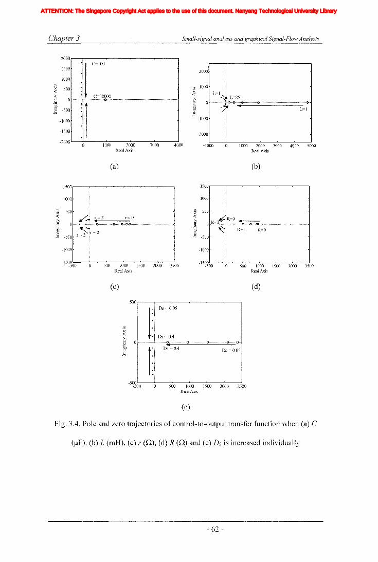
C-'hapter 3 Small-signal analysis and graphical Signal-Flow Analysis
2000,.....-----r---r-----r---.-...,.---,
1500
1000
2000
Ul 1000
~ L=I i,,~ L=25j:::: :~&.& ..•@ ••••••••.••••& .................•......................~~.;.
1000 2000 3000 4000 5000Real Axis
o-1000-2000L----'-0---1OJ-00---2-l001.-0---3....L00-O----J4000
Real Axis
'" j C=I00
"\V) .~
~ 500 :~~ :[ C=10000j .::.Jj,"O ,..» •••••••••• ,,, .
-1500 "\.~
(a) (b)
1500r----r----....--..,..----.-------,r----..., 1500r---.-----..---..----.-----..----,
1000
.~ 500<C /.: 1'=2 1'=0.i 0 ·· ·····:1··..·t O '0.00 mm
.
of) "°\=0~ -500 r= 2 \
1000
rJl 500 j~ .
~R=O~ 0 R~~ ..~ .. ) ~0 0 _ .
j .:::: ~I R~I R~O-1000
-15~~00 o 500 1000 1500 2000 2500Real Axis
o 500 1000 1500 2000 2500Real Axis
(c) (d)
500,.....---.....-------,...---.......----..---r----.
2500200015001000Real Axis
]
:1 Ds~005
" ~
.. I Ds = 0.4o m m~ ~ 0 m •• 0 m ••• ····0·······0·
1:1 Ds=O.4 Ds=0.05
.. ~M ~
"\_500L-----'-----I1....---l-----l--....L-----J
-500 0 500
(e)
Fig. 3.4. Pole and zero trajectories of control-to-output transfer function when (a) C
(/-IF), (b) L (nl1-I), (c) r (n), (d) R (n) and (e) Ds is increased individually
- 62 -
Iiq
Iod
Ioq
I odq
I max
1,Ie, Ici,Ic2IDC
IL_m
I MPP
IpvI scITHD
IzI Zn
lap*lap
Ia,Ip,IoIa *, Ip*,10*
Iah,Iphlin
12n
I;
afJ axis currentafJ axis reference currentafJO axis current componentsafJO axis reference current componentsafJ axis harmonic current componentsNeutral current of inverter 1Neutral current of inverter 2Zero sequence reference current
Average Z-source inductor currentPerturbed Z-source inductor current
Perturbed load currentConstantGain factor of fifth harmonics filterGain factor of seventh harmonics filterGain factor of eleventh harmonics filterDC side controller proportional gain of PI controllerDC side controller integral gain of PI controllerGain of the inverterIntegral gain of PI controller in current controllerGain of the hth resonance filterProportional gain of AC side inner loop controllerProportional gain of PI controller in current controllerProportional gain of zero sequence resonance controllerIntegral gain of the resonance controllerIntegral gain of the zero sequence resonance controllerIntegral gain of the hth resonance controllerProportional gain of AC side PI controllerIntegral gain of the AC side PI controllerMultiplying factor for harmonics eliminationDC side filter inductanceLoad inductanceNeutral inductanceGrid inductanceLeakage inductance of transformer
XVII
ATTENTION: The Singapore Copyright Act applies to the use of this document. Nanyang Technological University Library

Chapter 3 Small-signal analysis and graphical Signal-Flow Analysis
Table 3-1: System parameters used for simulating the ZSI
Parameter ValueVDC 150VILoad IDA
L 5mHC 1000~F
r 0.50R 0.03QDs 0.3
Fig.3.5 shows the experimental results obtained for a step change in shoot through
where shoot-through duty ratio is changed from Ds == 0.28 to 0.33. The experimental
results prove the presence of right hand half plane zero (RHHPZ) as predicted
theoretically in (3-5). Furthermore, simulations and experiments are carried out to
show the dynamics of the step response to validate the observed characteristic in root
locus analysis where only a zoomed view at the transient point is presented. Fig.3.6 (a)
and Fig. 3.6 (b) give simulation results obtained for different capacitor and inductor
values and this would clearly illustrate the presence of a RHHP zero and its variations
Where Fig.3.6 (a) and Fig. 3.6 (b) show the step responses of voltage VCl (or V C2)
across a Z-source capacitor, during a step change in shoot-through duty ratio from Ds
== 0.28 to 0.33 at t == 300ms (silTIulation is done with reduced voltage to comply with
experimental conditions). These figures clearly show Vel hence Vs decreasing initially
before rising towards their new steady-state values (which are non-minimum-phase
features for RHHP zero). Also Fig.3.6 (a) and Fig.3.6 (b) show the variation of under-
shoot with different inductor values and different capacitor values respectively. These
simulated results are experilnentally verified in Fig.3.? Six sets of experimental setups
are built using different capacitor and inductor values with conditions silnilar to the
simulation results. For each different setup, experiment is carried out separately and
results are obtained using digital oscilloscope which has storage capability. Then for
- 63 -
Iiq
Iod
Ioq
I odq
I max
1,Ie, Ici,Ic2IDC
IL_m
I MPP
IpvI scITHD
IzI Zn
lap*lap
Ia,Ip,IoIa *, Ip*,10*
Iah,Iphlin
12n
I;
afJ axis currentafJ axis reference currentafJO axis current componentsafJO axis reference current componentsafJ axis harmonic current componentsNeutral current of inverter 1Neutral current of inverter 2Zero sequence reference current
Average Z-source inductor currentPerturbed Z-source inductor current
Perturbed load currentConstantGain factor of fifth harmonics filterGain factor of seventh harmonics filterGain factor of eleventh harmonics filterDC side controller proportional gain of PI controllerDC side controller integral gain of PI controllerGain of the inverterIntegral gain of PI controller in current controllerGain of the hth resonance filterProportional gain of AC side inner loop controllerProportional gain of PI controller in current controllerProportional gain of zero sequence resonance controllerIntegral gain of the resonance controllerIntegral gain of the zero sequence resonance controllerIntegral gain of the hth resonance controllerProportional gain of AC side PI controllerIntegral gain of the AC side PI controllerMultiplying factor for harmonics eliminationDC side filter inductanceLoad inductanceNeutral inductanceGrid inductanceLeakage inductance of transformer
XVII
ATTENTION: The Singapore Copyright Act applies to the use of this document. Nanyang Technological University Library
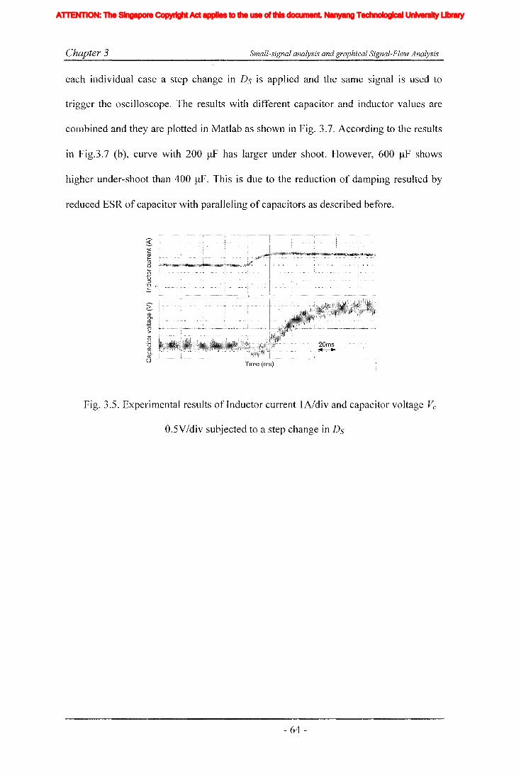
Chapter 3 Small-signal analysis and graphical Signal-Flow Analysis
each individual case a step change in Ds is applied and the same signal is used to
trigger the oscilloscope. The results with different capacitor and inductor values are
combined and they are plotted in Matlab as shown in Fig. 3.7. According to the results
in Fig.3.7 (b), curve with 200 ~lF has larger under shoot. However, 600 ~F shows
higher under-shoot than 400 ~F. This is due to the reduction of damping resulted by
reduced ESR of capacitor with paralleling of capacitors as described before.
~(!)0>
E'0>
B'0ro0..(3 .,:i.. , : : J:..' .1 j : ..
Time (ms)
Fig. 3.5. Experimental results of Inductor current IA/div and capacitor voltage Vc
0.5V/div subjected to a step change in Ds
- 64-
Iiq
Iod
Ioq
I odq
I max
1,Ie, Ici,Ic2IDC
IL_m
I MPP
IpvI scITHD
IzI Zn
lap*lap
Ia,Ip,IoIa *, Ip*,10*
Iah,Iphlin
12n
I;
afJ axis currentafJ axis reference currentafJO axis current componentsafJO axis reference current componentsafJ axis harmonic current componentsNeutral current of inverter 1Neutral current of inverter 2Zero sequence reference current
Average Z-source inductor currentPerturbed Z-source inductor current
Perturbed load currentConstantGain factor of fifth harmonics filterGain factor of seventh harmonics filterGain factor of eleventh harmonics filterDC side controller proportional gain of PI controllerDC side controller integral gain of PI controllerGain of the inverterIntegral gain of PI controller in current controllerGain of the hth resonance filterProportional gain of AC side inner loop controllerProportional gain of PI controller in current controllerProportional gain of zero sequence resonance controllerIntegral gain of the resonance controllerIntegral gain of the zero sequence resonance controllerIntegral gain of the hth resonance controllerProportional gain of AC side PI controllerIntegral gain of the AC side PI controllerMultiplying factor for harmonics eliminationDC side filter inductanceLoad inductanceNeutral inductanceGrid inductanceLeakage inductance of transformer
XVII
ATTENTION: The Singapore Copyright Act applies to the use of this document. Nanyang Technological University Library
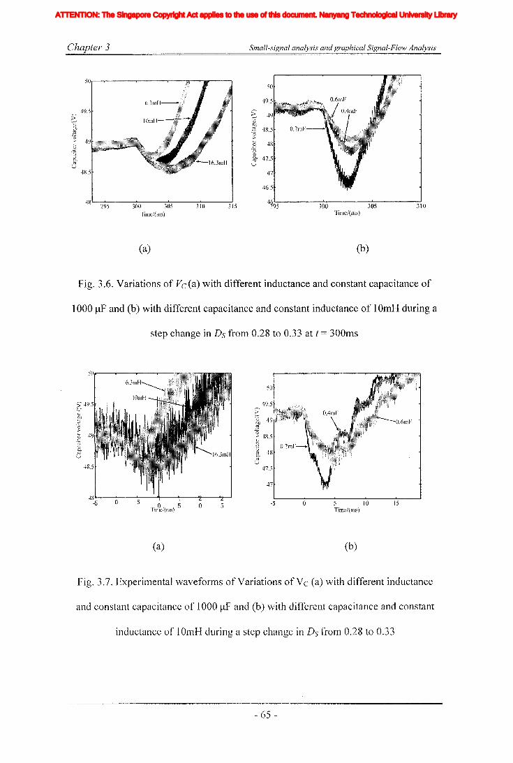
Chapter 3 Small-signal analysis and graphical Signal-Flow Analysis
48 295 300 305Time/(ms)
(a)
310 315 300 305Time/(ms)
(b)
310
Fig. 3.6. Variations of Vc (a) with different inductance and constant capacitance of
1000 IlF and (b) with different capacitance and constant inductance of 10mH during a
step change in Ds from 0.28 to 0.33 at t = 300ms
o 5Tin9c/(ms) 5
(a)
a 5 -5 o 5 lOTime!(ms)
(b)
15
Fig. 3.7. Experimental waveforms of Variations ofVc (a) with different inductance
and constant capacitance of 1000 IlF and (b) with different capacitance and constant
inductance of 10mH during a step change in Ds from 0.28 to 0.33
- 65 -
Iiq
Iod
Ioq
I odq
I max
1,Ie, Ici,Ic2IDC
IL_m
I MPP
IpvI scITHD
IzI Zn
lap*lap
Ia,Ip,IoIa *, Ip*,10*
Iah,Iphlin
12n
I;
afJ axis currentafJ axis reference currentafJO axis current componentsafJO axis reference current componentsafJ axis harmonic current componentsNeutral current of inverter 1Neutral current of inverter 2Zero sequence reference current
Average Z-source inductor currentPerturbed Z-source inductor current
Perturbed load currentConstantGain factor of fifth harmonics filterGain factor of seventh harmonics filterGain factor of eleventh harmonics filterDC side controller proportional gain of PI controllerDC side controller integral gain of PI controllerGain of the inverterIntegral gain of PI controller in current controllerGain of the hth resonance filterProportional gain of AC side inner loop controllerProportional gain of PI controller in current controllerProportional gain of zero sequence resonance controllerIntegral gain of the resonance controllerIntegral gain of the zero sequence resonance controllerIntegral gain of the hth resonance controllerProportional gain of AC side PI controllerIntegral gain of the AC side PI controllerMultiplying factor for harmonics eliminationDC side filter inductanceLoad inductanceNeutral inductanceGrid inductanceLeakage inductance of transformer
XVII
ATTENTION: The Singapore Copyright Act applies to the use of this document. Nanyang Technological University Library
Chapter 3 Small-signal analysis and graphical Signal-Flow Analysis
3.4 Possible methods for reducing the non-minimum phase
In the literature of power conversion topologies the occurrence of non-minimum
phase problem in the boost converters and buck-boost converters has been documented
and many researchers have proposed different methodologies to minimize and to
eliminate this problem. Reference [83] proposes a method to remove the RHHP zero
in boost converter by dynamically shifting it. This is done by changing the basic
structure of the boost converter and PWM switching scheme accordingly to introduce
additional degree of freedom. Then in reference [85], it is found that the leading edge
modulation and increasing of ESR of capacitor above a minimum value it is possible
to remove the RHHP zero in the boost converters. However, by increasing the ESR,
the voltage ripple increases. When this method is applied to ZSI it is observed that the
RHHP zero being pushed towards the imaginary axis, thereby it is expected
theoretically to have an increase in under-shoot. On the other hand, under-shoot is
damped by the movement of poles. However, this will result in increased ripple
voltage and the power losses. Therefore, applicability of this method with the sources
like fuel cell needs more concern. The method introduced in fixed frequency boost
converter in [86] demands a reduction in inductance and switching frequency while
keeping the capacitor ESR at a negligible value. It is observed that the reduction in
inductance is effective. However, this will not remove the RHHP zero in ZSIs instead
it shifts the zero further away from the imaginary axis. In addition reduction in
inductance will lead to increased current ripple. And sometimes it leads the converter
to operate in discontinuous conduction mode (DCM) which is not desirable. Therefore,
the selection of inductance is crucial. However, this not a free variable as it has to be
selected to suit the load requirements. In reference [87], smith-predictor-based
controller is used to eliminate the RHHP zero. As the poles and zero of ZSI are highly
- 66-
Iiq
Iod
Ioq
I odq
I max
1,Ie, Ici,Ic2IDC
IL_m
I MPP
IpvI scITHD
IzI Zn
lap*lap
Ia,Ip,IoIa *, Ip*,10*
Iah,Iphlin
12n
I;
afJ axis currentafJ axis reference currentafJO axis current componentsafJO axis reference current componentsafJ axis harmonic current componentsNeutral current of inverter 1Neutral current of inverter 2Zero sequence reference current
Average Z-source inductor currentPerturbed Z-source inductor current
Perturbed load currentConstantGain factor of fifth harmonics filterGain factor of seventh harmonics filterGain factor of eleventh harmonics filterDC side controller proportional gain of PI controllerDC side controller integral gain of PI controllerGain of the inverterIntegral gain of PI controller in current controllerGain of the hth resonance filterProportional gain of AC side inner loop controllerProportional gain of PI controller in current controllerProportional gain of zero sequence resonance controllerIntegral gain of the resonance controllerIntegral gain of the zero sequence resonance controllerIntegral gain of the hth resonance controllerProportional gain of AC side PI controllerIntegral gain of the AC side PI controllerMultiplying factor for harmonics eliminationDC side filter inductanceLoad inductanceNeutral inductanceGrid inductanceLeakage inductance of transformer
XVII
ATTENTION: The Singapore Copyright Act applies to the use of this document. Nanyang Technological University Library
Chapter 3 Small-signal analysis and graphical Signal-Flow Analysis
depend on the operating point, it would be difficult to predict the exact position of zero
and it would be very difficult to implement such predictor schen1es based on small
signal analysis.
From the available previous research work, it can be concluded that except in tri
state boost converter presented in [83], all other methods so far presented with boost
converters will not remove the RHHP zero. The applicability of this method is studied.
However, this requires insertion of additional two switches and the PWM scheme also
needs to be changed. A mathematical analysis is done and it has revealed the necessity
of insertion of additional free-wheeling state. This additional state has to ,be inserted
inside the null period and free-wheeling time has to be changed with the change of
switching duty ratio. This reduces the boosting capability. It limits the applicability in
a practical system and therefore the investigation details are not presented in this
thesis.
3.5 Discussion
In this chapter, the dynamic response of recently proposed ZSI is investigated. In
aiming that small-signal analysis and graphical signal-flow analyses are carried out for
deriving control transfer functions for the unique impedance network used in a ZSI.
The derived control-to-output transfer function shows the presence of a RHHP zero,
which causes the output Vs to decrease initially before start rising towards its new
steady-state value when a step increase is applied on control input Ds. This delayed
non-minimum-phase response can complicate inverter control, and its dependency on
system parameters can reduce the system robustness. Unfortunately, the identified
RHHP zero cannot be eliminated by adjusting the Z-source parameters, but its effect
can be reduced by reducing the Z-source network inductance L, and increase in
- 67 -
Iiq
Iod
Ioq
I odq
I max
1,Ie, Ici,Ic2IDC
IL_m
I MPP
IpvI scITHD
IzI Zn
lap*lap
Ia,Ip,IoIa *, Ip*,10*
Iah,Iphlin
12n
I;
afJ axis currentafJ axis reference currentafJO axis current componentsafJO axis reference current componentsafJ axis harmonic current componentsNeutral current of inverter 1Neutral current of inverter 2Zero sequence reference current
Average Z-source inductor currentPerturbed Z-source inductor current
Perturbed load currentConstantGain factor of fifth harmonics filterGain factor of seventh harmonics filterGain factor of eleventh harmonics filterDC side controller proportional gain of PI controllerDC side controller integral gain of PI controllerGain of the inverterIntegral gain of PI controller in current controllerGain of the hth resonance filterProportional gain of AC side inner loop controllerProportional gain of PI controller in current controllerProportional gain of zero sequence resonance controllerIntegral gain of the resonance controllerIntegral gain of the zero sequence resonance controllerIntegral gain of the hth resonance controllerProportional gain of AC side PI controllerIntegral gain of the AC side PI controllerMultiplying factor for harmonics eliminationDC side filter inductanceLoad inductanceNeutral inductanceGrid inductanceLeakage inductance of transformer
XVII
ATTENTION: The Singapore Copyright Act applies to the use of this document. Nanyang Technological University Library

Chapter 3 Small-signal analysis and graphical Signal-Flow Analysis
parasitic resistances rand R. Reducing the RHHP zero effect by adjusting system
parameters however is always accompanied by some negative effects such as
increased losses, ripples and system settling time. Lastly, simulation and experimental
results are presented for verifying the dynamic phenomena identified.
- 68 -
Iiq
Iod
Ioq
I odq
I max
1,Ie, Ici,Ic2IDC
IL_m
I MPP
IpvI scITHD
IzI Zn
lap*lap
Ia,Ip,IoIa *, Ip*,10*
Iah,Iphlin
12n
I;
afJ axis currentafJ axis reference currentafJO axis current componentsafJO axis reference current componentsafJ axis harmonic current componentsNeutral current of inverter 1Neutral current of inverter 2Zero sequence reference current
Average Z-source inductor currentPerturbed Z-source inductor current
Perturbed load currentConstantGain factor of fifth harmonics filterGain factor of seventh harmonics filterGain factor of eleventh harmonics filterDC side controller proportional gain of PI controllerDC side controller integral gain of PI controllerGain of the inverterIntegral gain of PI controller in current controllerGain of the hth resonance filterProportional gain of AC side inner loop controllerProportional gain of PI controller in current controllerProportional gain of zero sequence resonance controllerIntegral gain of the resonance controllerIntegral gain of the zero sequence resonance controllerIntegral gain of the hth resonance controllerProportional gain of AC side PI controllerIntegral gain of the AC side PI controllerMultiplying factor for harmonics eliminationDC side filter inductanceLoad inductanceNeutral inductanceGrid inductanceLeakage inductance of transformer
XVII
ATTENTION: The Singapore Copyright Act applies to the use of this document. Nanyang Technological University Library

Chapter 4 Development ofcomprehensive model and multi-loop controller for ZSI DG systems
Chapter 4
Development of comprehensive model and multi-loop
controller for ZSI DG systems
4.1 Introduction
Today's industrial loads are more sensitive to quality of voltage and such loads are
frequently protected by UPS systems [88]. However, due to many inherent advantages
onsite generations could be used as an alternative. In order to maintain the quality of
output voltage, a closed-loop controlling schemes can be adopted in on-site generating
schemes with the changing conditions like input voltage and load disturbances.
Moreover, sources like fuel-cells and solar cells exhibit larger operating range in the
output and they need closed-loop controlling to maintain the quality of voltage [8, 34].
Having studied the operation and characteristics of ZSI in previous chapters, this
chapter focuses on developing a comprehensive model and designing close loop
controllers for stand-alone type DO system. To date, most of the research work
published on controlling and applications of ZSI are of open-loop nature [14-16, 51]
except [17] where a closed-loop controller is designed with sliding mode controller in
the inverter side with space vector modulation and discrete controller controlling the
output of the Z-source impedance network. However, it does not consider the
dynamics of Z-source impedance network. In order to drive sensitive loads [89-92]
and also to connect to the utility it is necessary to regulate the output voltage and
current of the ZSI [93]. Furthermore, it is ilnportant to ride-through voltage dips and
- 69-
Iiq
Iod
Ioq
I odq
I max
1,Ie, Ici,Ic2IDC
IL_m
I MPP
IpvI scITHD
IzI Zn
lap*lap
Ia,Ip,IoIa *, Ip*,10*
Iah,Iphlin
12n
I;
afJ axis currentafJ axis reference currentafJO axis current componentsafJO axis reference current componentsafJ axis harmonic current componentsNeutral current of inverter 1Neutral current of inverter 2Zero sequence reference current
Average Z-source inductor currentPerturbed Z-source inductor current
Perturbed load currentConstantGain factor of fifth harmonics filterGain factor of seventh harmonics filterGain factor of eleventh harmonics filterDC side controller proportional gain of PI controllerDC side controller integral gain of PI controllerGain of the inverterIntegral gain of PI controller in current controllerGain of the hth resonance filterProportional gain of AC side inner loop controllerProportional gain of PI controller in current controllerProportional gain of zero sequence resonance controllerIntegral gain of the resonance controllerIntegral gain of the zero sequence resonance controllerIntegral gain of the hth resonance controllerProportional gain of AC side PI controllerIntegral gain of the AC side PI controllerMultiplying factor for harmonics eliminationDC side filter inductanceLoad inductanceNeutral inductanceGrid inductanceLeakage inductance of transformer
XVII
ATTENTION: The Singapore Copyright Act applies to the use of this document. Nanyang Technological University Library

Chapter 4 Development ofcomprehensive model and multi-loop controller for ZSJ DG systems
power frequency harmonics. Hence, designed controllers should be able to track the
reference and to reject the disturbances effectively.
Towards this end, large signal and small signal modeling techniques are used to
derive the inverter transfer functions and to design the controllers. AC and DC sides of
the inverter are modeled separately. AC-side parameters are transformed into
synchronous reference frame. Hence, fundamental frequency components appear as
DC signals and PI controllers are employed to remove the steady state error. For the
DC-side, an indirect controller is proposed because of the presence of RHHP zero in
the derived transfer functions. A new technique is proposed to prevent the undesirable
non-minimum phase effects due to RHHP zero being propagated into the AC-side.
Furthermore, a scheme to select parameters for proper functionality of the controller in
rejecting disturbances originating from both input and load is proposed. The efficacy
of proposed controllers is proved using simulations in Matlab/Simulink. Finally,
experimental results are presented to corroborate the disturbance rejection and
reference tracking capability of designed closed-loop controlled ZSI.
4.2 State-space-averaged switching model of the ZSI
Fig. 4.1 shows ZSI driving a load through a second order LC filter in the AC-side.
For the simplicity of modeling, AC and DC sides of the circuit are considered
separately, and the inverter is represented by a gain value appropriate to the
modulation index. First, consider the AC-side of the circuit. By applying Kirchhoff
voltage low (KVL) and Kirchhoff current low (KCL), (4-1) and (4-2) can be obtained
for each "x" (x = a, b, c) phase of the inverter.
- 70-
Iiq
Iod
Ioq
I odq
I max
1,Ie, Ici,Ic2IDC
IL_m
I MPP
IpvI scITHD
IzI Zn
lap*lap
Ia,Ip,IoIa *, Ip*,10*
Iah,Iphlin
12n
I;
afJ axis currentafJ axis reference currentafJO axis current componentsafJO axis reference current componentsafJ axis harmonic current componentsNeutral current of inverter 1Neutral current of inverter 2Zero sequence reference current
Average Z-source inductor currentPerturbed Z-source inductor current
Perturbed load currentConstantGain factor of fifth harmonics filterGain factor of seventh harmonics filterGain factor of eleventh harmonics filterDC side controller proportional gain of PI controllerDC side controller integral gain of PI controllerGain of the inverterIntegral gain of PI controller in current controllerGain of the hth resonance filterProportional gain of AC side inner loop controllerProportional gain of PI controller in current controllerProportional gain of zero sequence resonance controllerIntegral gain of the resonance controllerIntegral gain of the zero sequence resonance controllerIntegral gain of the hth resonance controllerProportional gain of AC side PI controllerIntegral gain of the AC side PI controllerMultiplying factor for harmonics eliminationDC side filter inductanceLoad inductanceNeutral inductanceGrid inductanceLeakage inductance of transformer
XVII
ATTENTION: The Singapore Copyright Act applies to the use of this document. Nanyang Technological University Library

Chapter 4 Development ofcomprehensive model and multi-loop controllerfor ZSI DC systems
r L
Voc
g
\lc:am Ita
m
Fig. 4.1. Three Phase ZSI
(4-1)
(4-2)
Where ilx==[ita ilb itc]~ i;x==[i;a iib i;c]T, Vgx==[Vga Vgb Vgc]T, Vgxm==[Vgam Vgbm Vgcm]T, p=d/dt
and vgm is voltage between points "g" and "m". When the top switch in the "x" phase
is ON vgx=vs and when bottom switch is ON vgx=O. If dx is the average switching duty
ratio (in this case it is fair to assume switching frequency is significantly higher than
power system frequency, hence switchings can be represented by an average switching
duty ratio [89, 93]), then vgx=vsdx. Also for a balanced three-phase load, LVx=O and
I:ix=O. Then from (4-1), it is possible to find the value of vgm as follows,
(4-3)
Then all the state equations in the abc domain are transformed into d-q rotating
reference frame to simplify the modeling and analysis. The transformation matrix is
given by (4-4) where "I' can be voltage or current. It is assumed that the system is
balanced and zero sequence cOlnponents do not exist. After the transformation, the
state equations are given in (4-5) to (4-8).
- 71 -
Iiq
Iod
Ioq
I odq
I max
1,Ie, Ici,Ic2IDC
IL_m
I MPP
IpvI scITHD
IzI Zn
lap*lap
Ia,Ip,IoIa *, Ip*,10*
Iah,Iphlin
12n
I;
afJ axis currentafJ axis reference currentafJO axis current componentsafJO axis reference current componentsafJ axis harmonic current componentsNeutral current of inverter 1Neutral current of inverter 2Zero sequence reference current
Average Z-source inductor currentPerturbed Z-source inductor current
Perturbed load currentConstantGain factor of fifth harmonics filterGain factor of seventh harmonics filterGain factor of eleventh harmonics filterDC side controller proportional gain of PI controllerDC side controller integral gain of PI controllerGain of the inverterIntegral gain of PI controller in current controllerGain of the hth resonance filterProportional gain of AC side inner loop controllerProportional gain of PI controller in current controllerProportional gain of zero sequence resonance controllerIntegral gain of the resonance controllerIntegral gain of the zero sequence resonance controllerIntegral gain of the hth resonance controllerProportional gain of AC side PI controllerIntegral gain of the AC side PI controllerMultiplying factor for harmonics eliminationDC side filter inductanceLoad inductanceNeutral inductanceGrid inductanceLeakage inductance of transformer
XVII
ATTENTION: The Singapore Copyright Act applies to the use of this document. Nanyang Technological University Library
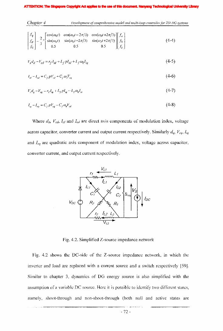
Chapter 4 Development ofcomprehensive model and multi-loop controllerfor ZSI DG systems
(4-4)
(4-5)
(4-6)
(4-7)
(4-8)
Where dd' Vcd, lid and lad are direct axis cOlnponents of modulation index, voltage
across capacitor, converter current and output current respectively. Similarly dq, Vcq, liq
and laq are quadratic axis component of modulation index, voltage across capacitor,
converter current, and output current respectively.
VDC _
Fig. 4.2. Simplified Z-source impedance network
Fig. 4.2 shows the DC-side of the Z-soufce impedance network, in which the
inverter and load are replaced with a current source and a switch respectively [59].
Similar to chapter 3, dynamics of DG energy source is also simplified with the
asslunption of a variable DC source. Here it is possible to identify two different states,
namely, shoot-through and non-shoat-through (both null and active states are
- 72 -
Iiq
Iod
Ioq
I odq
I max
1,Ie, Ici,Ic2IDC
IL_m
I MPP
IpvI scITHD
IzI Zn
lap*lap
Ia,Ip,IoIa *, Ip*,10*
Iah,Iphlin
12n
I;
afJ axis currentafJ axis reference currentafJO axis current componentsafJO axis reference current componentsafJ axis harmonic current componentsNeutral current of inverter 1Neutral current of inverter 2Zero sequence reference current
Average Z-source inductor currentPerturbed Z-source inductor current
Perturbed load currentConstantGain factor of fifth harmonics filterGain factor of seventh harmonics filterGain factor of eleventh harmonics filterDC side controller proportional gain of PI controllerDC side controller integral gain of PI controllerGain of the inverterIntegral gain of PI controller in current controllerGain of the hth resonance filterProportional gain of AC side inner loop controllerProportional gain of PI controller in current controllerProportional gain of zero sequence resonance controllerIntegral gain of the resonance controllerIntegral gain of the zero sequence resonance controllerIntegral gain of the hth resonance controllerProportional gain of AC side PI controllerIntegral gain of the AC side PI controllerMultiplying factor for harmonics eliminationDC side filter inductanceLoad inductanceNeutral inductanceGrid inductanceLeakage inductance of transformer
XVII
ATTENTION: The Singapore Copyright Act applies to the use of this document. Nanyang Technological University Library
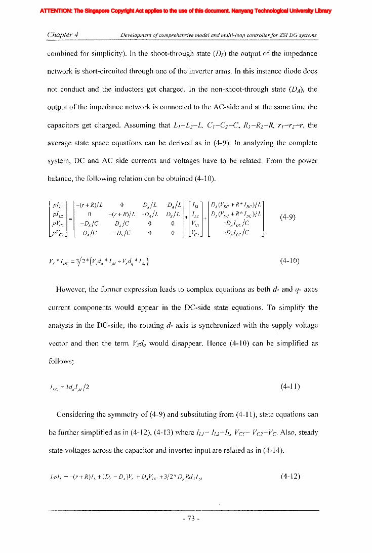
Chapter 4 Development ofcomprehensive model and multi-loop controller for ZSI DG systems
combined for simplicity). In the shoot-through state (Ds) the output of the impedance
network is short-circuited through one of the inverter arms. In this instance diode does
not conduct and the inductors get charged. In the non-shoot-through state (DA), the
output of the impedance network is connected to the AC-side and at the same time the
average state space equations can be derived as in (4-9). In analyzing the complete
system, DC and AC side currents and voltages have to be related. From the power
balance, the following relation can be obtained (4-10).
[PILI l_(r+R)/L 0 Ds/L -DA/L1',1 jlDA(VJX: +R* IDcJ/Lj
pILl = 0 -(r+R)/L -DAIL Ds/L * In + DA(Voc+R*IDd/L (4-9)pVCI -Ds/C DA/C 0 0 VCI -DAIDclc
pVC2 DA/C -Ds/C 0 0 VC2 -DAIDC Ic
(4-10)
However, the former expression leads to complex equations as both d- and q- axes
current components would appear in the DC-side state equations. To simplify the
analysis in the DC-side, the rotating d- axis is synchronized with the supply voltage
vector and then the term Vsdq would disappear. Hence (4-10) can be simplified as
follows;
(4-11)
Considering the symmetry of (4-9) and substituting from (4-11), state equations can
be further simplified as in (4-12), (4-13) where ILl = 1L2=1L, VCl= VC2=VC. Also, steady
state voltages across the capacitor and inverter input are related as in (4-14).
(4-12)
- 73 -
Iiq
Iod
Ioq
I odq
I max
1,Ie, Ici,Ic2IDC
IL_m
I MPP
IpvI scITHD
IzI Zn
lap*lap
Ia,Ip,IoIa *, Ip*,10*
Iah,Iphlin
12n
I;
afJ axis currentafJ axis reference currentafJO axis current componentsafJO axis reference current componentsafJ axis harmonic current componentsNeutral current of inverter 1Neutral current of inverter 2Zero sequence reference current
Average Z-source inductor currentPerturbed Z-source inductor current
Perturbed load currentConstantGain factor of fifth harmonics filterGain factor of seventh harmonics filterGain factor of eleventh harmonics filterDC side controller proportional gain of PI controllerDC side controller integral gain of PI controllerGain of the inverterIntegral gain of PI controller in current controllerGain of the hth resonance filterProportional gain of AC side inner loop controllerProportional gain of PI controller in current controllerProportional gain of zero sequence resonance controllerIntegral gain of the resonance controllerIntegral gain of the zero sequence resonance controllerIntegral gain of the hth resonance controllerProportional gain of AC side PI controllerIntegral gain of the AC side PI controllerMultiplying factor for harmonics eliminationDC side filter inductanceLoad inductanceNeutral inductanceGrid inductanceLeakage inductance of transformer
XVII
ATTENTION: The Singapore Copyright Act applies to the use of this document. Nanyang Technological University Library

Chapter 4 Development ofcomprehensive model and multi-loop controller for ZSJ DC systems
(4-13)
(4-14)
4.3 Control methodology
The purpose of designing closed-loop controllers is to achieve good output voltage
tracking and disturbance rejection. Hence, control variables are changed continuously
with the variations in system inputs and outputs. The present system has multiple
inputs and outputs. And both the control parameters are dependent on each other to
some extent as change in one parameter imposes a limitation on the freedom of the
other. This is because the shoot-through time is inserted inside the null period of the
PWM switching pattern as described in [14, 51]. This limitation makes controlling of
the inverter a challenging one. However, by studying the system dynamics, separation
of the system into two sub-systems would reduce system complexity as DC-side
subsystem has slower dynamics compared to the AC-side subsystem [94].
Subsequently, the separate controllers are designed for each independent unit, namely,
voltage source inverter and boost converter. The inverter operates in buck-boost mode
(need of this is described in section 4.4) by having the virtue of variable modulation
index varied from the set point, and Z-source impedance network which acts as a boost
converter with a large boosting factor.
In controlling the AC-side, synchronous frame PI regulators are used along with
inner current and outer voltage loops. Inner current loop gives a faster response and
stabilizes the output for a current disturbance. Slower variations are stabilized and
good reference tracking is achieved with the outer voltage loop. However, the source
input voltage can be small in magnitude and could show very large variations. Hence,
to support a stable output voltage at the AC-side, the DC-side voltage is boosted with
- 74 -
Iiq
Iod
Ioq
I odq
I max
1,Ie, Ici,Ic2IDC
IL_m
I MPP
IpvI scITHD
IzI Zn
lap*lap
Ia,Ip,IoIa *, Ip*,10*
Iah,Iphlin
12n
I;
afJ axis currentafJ axis reference currentafJO axis current componentsafJO axis reference current componentsafJ axis harmonic current componentsNeutral current of inverter 1Neutral current of inverter 2Zero sequence reference current
Average Z-source inductor currentPerturbed Z-source inductor current
Perturbed load currentConstantGain factor of fifth harmonics filterGain factor of seventh harmonics filterGain factor of eleventh harmonics filterDC side controller proportional gain of PI controllerDC side controller integral gain of PI controllerGain of the inverterIntegral gain of PI controller in current controllerGain of the hth resonance filterProportional gain of AC side inner loop controllerProportional gain of PI controller in current controllerProportional gain of zero sequence resonance controllerIntegral gain of the resonance controllerIntegral gain of the zero sequence resonance controllerIntegral gain of the hth resonance controllerProportional gain of AC side PI controllerIntegral gain of the AC side PI controllerMultiplying factor for harmonics eliminationDC side filter inductanceLoad inductanceNeutral inductanceGrid inductanceLeakage inductance of transformer
XVII
ATTENTION: The Singapore Copyright Act applies to the use of this document. Nanyang Technological University Library
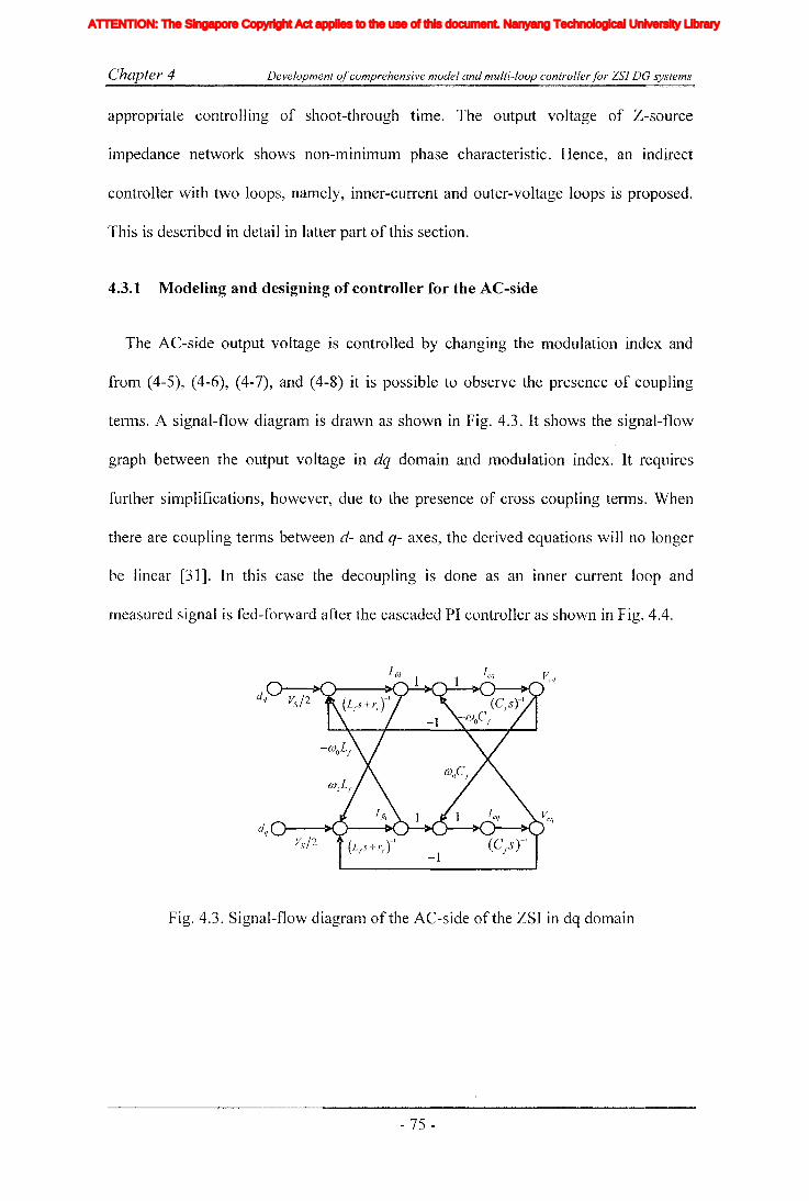
Chapter 4 Development ofcomprehensive model and multi-loop controllerfor ZSI DG systems
appropriate controlling of shoot-through time. The output voltage of Z-source
impedance network shows non-mlnnTIUm phase characteristic. Hence, an indirect
controller with two loops, namely, inner-current and outer-voltage loops is proposed.
This is described in detail in latter part of this section.
4.3.1 Modeling and designing of controller for the AC-side
The AC-side output voltage is controlled by changing the lTIodulation index and
from (4-5), (4-6), (4-7), and (4-8) it is possible to observe the presence of coupling
terms. A signal-flow diagram is drawn as shown in Fig. 4.3. It shows the signal-flow
graph between the output voltage in dq domain and modulation index. It requires
further simplifications, however, due to the presence of cross coupling terms. When
there are coupling terms between d- and q- axes, the derived equations will no longer
be linear [31]. In this case the decoupling is done as an inner current loop and
measured signal is fed-forward after the cascaded PI controller as shown in Fig. 4.4.
Fig. 4.3. Signal-flow diagram of the AC-side of the ZSI in dq domain
- 75 -
Iiq
Iod
Ioq
I odq
I max
1,Ie, Ici,Ic2IDC
IL_m
I MPP
IpvI scITHD
IzI Zn
lap*lap
Ia,Ip,IoIa *, Ip*,10*
Iah,Iphlin
12n
I;
afJ axis currentafJ axis reference currentafJO axis current componentsafJO axis reference current componentsafJ axis harmonic current componentsNeutral current of inverter 1Neutral current of inverter 2Zero sequence reference current
Average Z-source inductor currentPerturbed Z-source inductor current
Perturbed load currentConstantGain factor of fifth harmonics filterGain factor of seventh harmonics filterGain factor of eleventh harmonics filterDC side controller proportional gain of PI controllerDC side controller integral gain of PI controllerGain of the inverterIntegral gain of PI controller in current controllerGain of the hth resonance filterProportional gain of AC side inner loop controllerProportional gain of PI controller in current controllerProportional gain of zero sequence resonance controllerIntegral gain of the resonance controllerIntegral gain of the zero sequence resonance controllerIntegral gain of the hth resonance controllerProportional gain of AC side PI controllerIntegral gain of the AC side PI controllerMultiplying factor for harmonics eliminationDC side filter inductanceLoad inductanceNeutral inductanceGrid inductanceLeakage inductance of transformer
XVII
ATTENTION: The Singapore Copyright Act applies to the use of this document. Nanyang Technological University Library

Chapter 4
~dq
Development ofcomprehensive model and multi-loop controller for ZSI DG systems
-1
Fig. 4.4. Signal-flow graph of the decoupled system with closed current and voltage
loops decoupled as inner-loop controller
Where H ==K +K .s-land H =K.v Vp v, I Ip
~----------------------------I
III
"-----..o.J----L~ l.o.o-&~-'I-.6: yZ. _dqIII____________________________ J
Fig. 4.5. Block diagram of the AC-side closed loop controller
Dotted box in Fig. 4.5 shows the block diagram for designing the inner current loop.
Capacitor current measurement is used as the feed-back signal and the load current is
used as a disturbance current. From the Mason's gain rule it is possible to obtain the
open-loop transfer functions for d- and q- axes as in (4-15). These transfer functions
are used to obtain the Bode diagrams and Fig. 4.6 shows the open-loop Bode diagram
of inner current loop which has a high crossover frequency of 11 kHz. However, it is
necessary to reduce the bandwidth as the power semiconductors switches operate only
at 10kHz. Generally, for switching circuits frequency response is valid only up to half
the switching frequency [89, 93], and the crossover frequency should be selected to
remove the switching harmonics. Presence of harmonics would cause number of zero
crossings to be increased in the reference signal hence it could disturb the functionality
- 76-
Iiq
Iod
Ioq
I odq
I max
1,Ie, Ici,Ic2IDC
IL_m
I MPP
IpvI scITHD
IzI Zn
lap*lap
Ia,Ip,IoIa *, Ip*,10*
Iah,Iphlin
12n
I;
afJ axis currentafJ axis reference currentafJO axis current componentsafJO axis reference current componentsafJ axis harmonic current componentsNeutral current of inverter 1Neutral current of inverter 2Zero sequence reference current
Average Z-source inductor currentPerturbed Z-source inductor current
Perturbed load currentConstantGain factor of fifth harmonics filterGain factor of seventh harmonics filterGain factor of eleventh harmonics filterDC side controller proportional gain of PI controllerDC side controller integral gain of PI controllerGain of the inverterIntegral gain of PI controller in current controllerGain of the hth resonance filterProportional gain of AC side inner loop controllerProportional gain of PI controller in current controllerProportional gain of zero sequence resonance controllerIntegral gain of the resonance controllerIntegral gain of the zero sequence resonance controllerIntegral gain of the hth resonance controllerProportional gain of AC side PI controllerIntegral gain of the AC side PI controllerMultiplying factor for harmonics eliminationDC side filter inductanceLoad inductanceNeutral inductanceGrid inductanceLeakage inductance of transformer
XVII
ATTENTION: The Singapore Copyright Act applies to the use of this document. Nanyang Technological University Library

Chapter 4 Development ofcomprehensive model and multi-loop controllerfor ZSI DG systems
of the PWM generator. On the other hand high bandwidth is desirable in order to have
a fast response and perfect reference tracking; accordingly the cutoff frequency is
adjusted. To achieve the suitable bandwidth, the proportional controller is cascaded
with Kip ==0.133. The adjusted Bode diagram is shown in Fig. 4.7. It has a cross-over
frequency of 1.5 kHz and phase margin of 90.2. There is also a second crossover at
49.6Hz with phase margin of -91.5. Closed-loop Bode diagram is given in Fig. 4.8.
Equation (4-16) gives the closed-loop transfer function.
(4-15)
(4-16)
80,.-------.------~------..
60
~- 40v
'"d.~ 20~ 0 ._._.-._. _._.-.-._._._.-.-._._.-.-._._._._._.-
~-20
-~8----e-----=::-----~-----.,
~ 45'"d
~ 0~
~ -45
-90"------...L.-~=--- ......----....() 2 4 6
10 10 10 10Frequency (Hz)
Fig. 4.6. Open-loop Bode diagram of inner current loop
- 77 -
Iiq
Iod
Ioq
I odq
I max
1,Ie, Ici,Ic2IDC
IL_m
I MPP
IpvI scITHD
IzI Zn
lap*lap
Ia,Ip,IoIa *, Ip*,10*
Iah,Iphlin
12n
I;
afJ axis currentafJ axis reference currentafJO axis current componentsafJO axis reference current componentsafJ axis harmonic current componentsNeutral current of inverter 1Neutral current of inverter 2Zero sequence reference current
Average Z-source inductor currentPerturbed Z-source inductor current
Perturbed load currentConstantGain factor of fifth harmonics filterGain factor of seventh harmonics filterGain factor of eleventh harmonics filterDC side controller proportional gain of PI controllerDC side controller integral gain of PI controllerGain of the inverterIntegral gain of PI controller in current controllerGain of the hth resonance filterProportional gain of AC side inner loop controllerProportional gain of PI controller in current controllerProportional gain of zero sequence resonance controllerIntegral gain of the resonance controllerIntegral gain of the zero sequence resonance controllerIntegral gain of the hth resonance controllerProportional gain of AC side PI controllerIntegral gain of the AC side PI controllerMultiplying factor for harmonics eliminationDC side filter inductanceLoad inductanceNeutral inductanceGrid inductanceLeakage inductance of transformer
XVII
ATTENTION: The Singapore Copyright Act applies to the use of this document. Nanyang Technological University Library
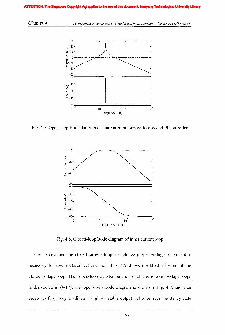
Chapter 4 Development ofcomprehensive model and multi-loop controller for ZSI DG systems
60r------,.------..,...-------,
,,--.-. 40p:j
:s 20q)
'1j.g 0 '-'.'-'-'.'-'.'-'-'.' •.•.•.- .•.•._.•.•
~J} -20~
-40
r--- 45~
'1j
';j;' 0~
if: -45
-90"--- ....L.----=.:::=_----__---'o 'J 4 6
10 10- 10 10
Frequency (Hz)
Fig. 4.7. Open-loop Bode diagram of inner current loop with cascaded PI controller
O,.-------:;poo--=-------,..-------..
bJ3 45(\)
'1j
~ 0~
..cp... -45
-90"'- -.L- L..::=====........,._..Io :2 4 6
10 10 10 10Frequency (Hz)
Fig. 4.8. Closed-loop Bode diagram of inner current loop
Having designed the closed current loop, to achieve proper voltage tracking it is
necessary to have a closed voltage loop. Fig. 4.5 shows the block diagram of the
closed voltage loop. Then open-loop transfer function of d- and q- axes voltage loops
is derived as in (4-17). The open-loop Bode diagralll is shown in Fig. 4.9, and then
crossover frequency is adjusted to give a stable output and to remove the steady state
- 78 -
Iiq
Iod
Ioq
I odq
I max
1,Ie, Ici,Ic2IDC
IL_m
I MPP
IpvI scITHD
IzI Zn
lap*lap
Ia,Ip,IoIa *, Ip*,10*
Iah,Iphlin
12n
I;
afJ axis currentafJ axis reference currentafJO axis current componentsafJO axis reference current componentsafJ axis harmonic current componentsNeutral current of inverter 1Neutral current of inverter 2Zero sequence reference current
Average Z-source inductor currentPerturbed Z-source inductor current
Perturbed load currentConstantGain factor of fifth harmonics filterGain factor of seventh harmonics filterGain factor of eleventh harmonics filterDC side controller proportional gain of PI controllerDC side controller integral gain of PI controllerGain of the inverterIntegral gain of PI controller in current controllerGain of the hth resonance filterProportional gain of AC side inner loop controllerProportional gain of PI controller in current controllerProportional gain of zero sequence resonance controllerIntegral gain of the resonance controllerIntegral gain of the zero sequence resonance controllerIntegral gain of the hth resonance controllerProportional gain of AC side PI controllerIntegral gain of the AC side PI controllerMultiplying factor for harmonics eliminationDC side filter inductanceLoad inductanceNeutral inductanceGrid inductanceLeakage inductance of transformer
XVII
ATTENTION: The Singapore Copyright Act applies to the use of this document. Nanyang Technological University Library
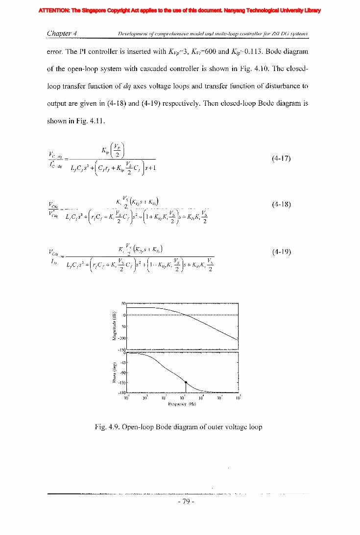
C-'hapter 4 Development ofcomprehensive model and multi-loop controller for ZSl DG systems
error. The PI controller is inserted with KVp=3,Kv;=600 and Kip=O.113. Bode diagram
of the open-loop system with cascaded controller is shown in Fig. 4.10. The closed-
loop transfer function of dq axes voltage loops and transfer function of disturbance to
output are given in (4-18) and (4-19) respectively. Then closed-loop Bode diagram is
shown in Fig. 4.11.
VC _ dq
I~_dq(4-17)
~ 0 ._._._._._._._._._._._._._._._._._._._.
(\)
] -50'8
CI)
~ -100
en -45.g'i' -90~
.L:Po< -135
-180'"--....-..---...................~....-..J..._--.~---~1~ Id 16 1~ 1~ Id 1~
Frequency (Hz)
Fig. 4.9. Open-loop Bode diagram of outer voltage loop
- 79-
(4-18)
(4-19)
Iiq
Iod
Ioq
I odq
I max
1,Ie, Ici,Ic2IDC
IL_m
I MPP
IpvI scITHD
IzI Zn
lap*lap
Ia,Ip,IoIa *, Ip*,10*
Iah,Iphlin
12n
I;
afJ axis currentafJ axis reference currentafJO axis current componentsafJO axis reference current componentsafJ axis harmonic current componentsNeutral current of inverter 1Neutral current of inverter 2Zero sequence reference current
Average Z-source inductor currentPerturbed Z-source inductor current
Perturbed load currentConstantGain factor of fifth harmonics filterGain factor of seventh harmonics filterGain factor of eleventh harmonics filterDC side controller proportional gain of PI controllerDC side controller integral gain of PI controllerGain of the inverterIntegral gain of PI controller in current controllerGain of the hth resonance filterProportional gain of AC side inner loop controllerProportional gain of PI controller in current controllerProportional gain of zero sequence resonance controllerIntegral gain of the resonance controllerIntegral gain of the zero sequence resonance controllerIntegral gain of the hth resonance controllerProportional gain of AC side PI controllerIntegral gain of the AC side PI controllerMultiplying factor for harmonics eliminationDC side filter inductanceLoad inductanceNeutral inductanceGrid inductanceLeakage inductance of transformer
XVII
ATTENTION: The Singapore Copyright Act applies to the use of this document. Nanyang Technological University Library

Chapter 4 Development ofcomprehensive model and multi-loop controllerfor ZSI DG systems
50~-------r-------Y-------.
~ 0 '-'-'-'-'-'-'-'-'-'-'-'-'-'-'-'-'-
<l)
"0.3 -50'2gp~ -100
-180 .....0..-------
2-..L.----""'"'4....;;;;:;;;~--~6
10 10 10 10Frequency (Hz)
Fig. 4.10. Open-loop Bode diagram of outer voltage loop with cascaded PI controller
o..----~............---~- ...................----.--.....................--~....-.......-20
~- -40<l)
~ -60
~ -80~
-100
-I21l '----.................."'-----.......................'---'-..........................---'-.........................--'--'...............~
b:O -45<l)
'"d'i -90...GA-. -135
-180 '"-)--'--'-..............o.oL-~"""-'-..............o.L.3--'--'..........u--.....L-
4::::;::::;:::c:a:1IZI=5==-=~6
10 10- 10 10 10 10
Frequency (Hz)
Fig. 4.11. Closed-loop Bode diagram of the outer voltage loop
4.3.2 Modeling and designing of controllers for the Z-source impedance
network
The AC-side voltage disturbances would have mInImum effect on the DC-side
except the changes in load current, which could alter the load current of the Z-source
impedance network. However, load current variation can be considered as a
disturbance in the AC-side and can be compensated for. However, to prevent clashes
- 80-
Iiq
Iod
Ioq
I odq
I max
1,Ie, Ici,Ic2IDC
IL_m
I MPP
IpvI scITHD
IzI Zn
lap*lap
Ia,Ip,IoIa *, Ip*,10*
Iah,Iphlin
12n
I;
afJ axis currentafJ axis reference currentafJO axis current componentsafJO axis reference current componentsafJ axis harmonic current componentsNeutral current of inverter 1Neutral current of inverter 2Zero sequence reference current
Average Z-source inductor currentPerturbed Z-source inductor current
Perturbed load currentConstantGain factor of fifth harmonics filterGain factor of seventh harmonics filterGain factor of eleventh harmonics filterDC side controller proportional gain of PI controllerDC side controller integral gain of PI controllerGain of the inverterIntegral gain of PI controller in current controllerGain of the hth resonance filterProportional gain of AC side inner loop controllerProportional gain of PI controller in current controllerProportional gain of zero sequence resonance controllerIntegral gain of the resonance controllerIntegral gain of the zero sequence resonance controllerIntegral gain of the hth resonance controllerProportional gain of AC side PI controllerIntegral gain of the AC side PI controllerMultiplying factor for harmonics eliminationDC side filter inductanceLoad inductanceNeutral inductanceGrid inductanceLeakage inductance of transformer
XVII
ATTENTION: The Singapore Copyright Act applies to the use of this document. Nanyang Technological University Library

Chapter 4 Development ofcomprehensive model and multi-loop controllerfor ZSJ DG systems
between dynamics of AC and DC sides, the DC-side dynamics should be made
considerably slower. This could be supported by having a higher bandwidth in the AC
side voltage and current loops. Also a cushioning method is proposed in the next
section to avoid the transferring of DC-side disturbance into the AC-side.
Fig. 4.12. Block diagram representation of Z-source impedance network
Consider the state space average equations derived in section 4.2. Some of these
equations contain nonlinear terms. Hence, small signal analysis is performed to obtain
a linear model of the Z-source impedance network. Its block diagram representation is
shown in Fig. 4.12, which shows the relationship between state variables and the
shoot-through duty ratio, where Vll=2Vc-VDC-RIDC and IlJ=2IL-IDc. From Fig. 4.12 it
is possible to derive the transfer function of VsIDs as in (4-20). It is evident from (4-
20) that there is a RHHP zero in the transfer function Vs IDs and also the transfer
function is semi proper. Furthermore, semi properness of the system transfer function
Inakes controller designing more difficult. I-Iowever, by analyzing system block
diagram, it is clear that semi-properness arises due the term V!, and the average value
of V L is zero. Moreover, its' effect is observable even in the output voltage of Z
source impedance network, which is pulsating. Hence, the output voltage of Z-source
impedance network is unsuitable as a feedback signaL To overcome these difficulties a
simple model is proposed in which the system is considered up to vc and then steady
- 81 -
Iiq
Iod
Ioq
I odq
I max
1,Ie, Ici,Ic2IDC
IL_m
I MPP
IpvI scITHD
IzI Zn
lap*lap
Ia,Ip,IoIa *, Ip*,10*
Iah,Iphlin
12n
I;
afJ axis currentafJ axis reference currentafJO axis current componentsafJO axis reference current componentsafJ axis harmonic current componentsNeutral current of inverter 1Neutral current of inverter 2Zero sequence reference current
Average Z-source inductor currentPerturbed Z-source inductor current
Perturbed load currentConstantGain factor of fifth harmonics filterGain factor of seventh harmonics filterGain factor of eleventh harmonics filterDC side controller proportional gain of PI controllerDC side controller integral gain of PI controllerGain of the inverterIntegral gain of PI controller in current controllerGain of the hth resonance filterProportional gain of AC side inner loop controllerProportional gain of PI controller in current controllerProportional gain of zero sequence resonance controllerIntegral gain of the resonance controllerIntegral gain of the zero sequence resonance controllerIntegral gain of the hth resonance controllerProportional gain of AC side PI controllerIntegral gain of the AC side PI controllerMultiplying factor for harmonics eliminationDC side filter inductanceLoad inductanceNeutral inductanceGrid inductanceLeakage inductance of transformer
XVII
ATTENTION: The Singapore Copyright Act applies to the use of this document. Nanyang Technological University Library
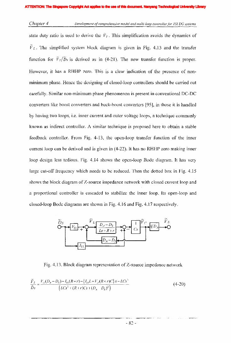
Chapter 4 Development ofcomprehensive model and multi-loop controllerfor ZSI DG systems
state duty ratio is used to derive the Vs. This simplification avoids the dynamics of
VL. The simplified system block diagram is given in Fig. 4.13 and the transfer
function for VsIDs is derived as in (4-21). The new transfer function is proper.
However, it has a RHHP zero. This is a clear indication of the presence of non-
minimum phase. Hence the designing of closed-loop controllers should be carried out
carefully. Similar non-minimum phase phenomenon is present in conventional DC-DC
converters like boost converters and buck-boost converters [95], in those it is handled
by having two loops, i.e. inner current and outer voltage loops, a technique commonly
known as indirect controller. A similar technique is proposed here to obtain a stable
feedback controller. From Fig. 4-13, the open-loop transfer function of the inner
cun~ent loop can be derived and is given in (4-22). It has no RHHP zero making inner
loop design less tedious. Fig. 4.14 shows the open-loop Bode diagram. It has very
large cut-off frequency which needs to be reduced. Then the dotted box in Fig. 4.15
shows the block diagram of Z-source impedance network with closed current loop and
a proportional controller is cascaded to stabilize the inner loop. Its open-loop and
closed-loop Bode diagrams are shown in Fig. 4.16 and Fig. 4.17 respectively.
Fig. 4.13. Block diagralTI representation of Z-source impedance network
VS ~I (DA - Ds )- 111 (R+r)-{ JIlL + ~I (R+r)C} s- LCs2
Ds (LCs2+(R+r)Cs+(DA-DS)2)
- 82 -
(4-20)
Iiq
Iod
Ioq
I odq
I max
1,Ie, Ici,Ic2IDC
IL_m
I MPP
IpvI scITHD
IzI Zn
lap*lap
Ia,Ip,IoIa *, Ip*,10*
Iah,Iphlin
12n
I;
afJ axis currentafJ axis reference currentafJO axis current componentsafJO axis reference current componentsafJ axis harmonic current componentsNeutral current of inverter 1Neutral current of inverter 2Zero sequence reference current
Average Z-source inductor currentPerturbed Z-source inductor current
Perturbed load currentConstantGain factor of fifth harmonics filterGain factor of seventh harmonics filterGain factor of eleventh harmonics filterDC side controller proportional gain of PI controllerDC side controller integral gain of PI controllerGain of the inverterIntegral gain of PI controller in current controllerGain of the hth resonance filterProportional gain of AC side inner loop controllerProportional gain of PI controller in current controllerProportional gain of zero sequence resonance controllerIntegral gain of the resonance controllerIntegral gain of the zero sequence resonance controllerIntegral gain of the hth resonance controllerProportional gain of AC side PI controllerIntegral gain of the AC side PI controllerMultiplying factor for harmonics eliminationDC side filter inductanceLoad inductanceNeutral inductanceGrid inductanceLeakage inductance of transformer
XVII
ATTENTION: The Singapore Copyright Act applies to the use of this document. Nanyang Technological University Library
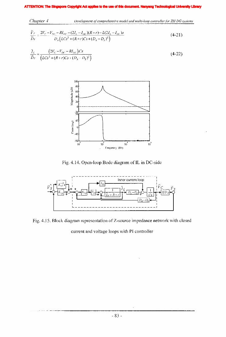
Chapter 4 Development ofcomprehensive model and multi-loop controllerfor ZSI DG systems
Vs 2Vc -VDC -RIDe -(211. -IDc )(R+r)-L(2JL -JDC)s
Ds DA(LCs2+(R+r)Cs+(DA-DS)2)
I L (2Vc - VDC - RIDC ) Cs-::::::;:--
Ds (LCs2+(R+r)Cs+(DA-DS)2)
100,-------.....-------.--------.
Pi 80
::::?, 60
] 40'8~ 20~ o ._._._._._._.-.-._._._._.-.-._.-.-._._._._._._._._.-.-._._._.-.-. _.-._._._.-
-90"-O------.J-Z...:::::...===-----4--oolI~-""610 10 10 10
Frequency (Hz)
Fig. 4.14. Open-loop Bode diagram of IL in DC-side
IIII IL J
(4-21 )
(4-22)
Fig. 4.15. Block diagram representation of Z-source impedance network with closed
current and voltage loops with PI controller
- 83 -
Iiq
Iod
Ioq
I odq
I max
1,Ie, Ici,Ic2IDC
IL_m
I MPP
IpvI scITHD
IzI Zn
lap*lap
Ia,Ip,IoIa *, Ip*,10*
Iah,Iphlin
12n
I;
afJ axis currentafJ axis reference currentafJO axis current componentsafJO axis reference current componentsafJ axis harmonic current componentsNeutral current of inverter 1Neutral current of inverter 2Zero sequence reference current
Average Z-source inductor currentPerturbed Z-source inductor current
Perturbed load currentConstantGain factor of fifth harmonics filterGain factor of seventh harmonics filterGain factor of eleventh harmonics filterDC side controller proportional gain of PI controllerDC side controller integral gain of PI controllerGain of the inverterIntegral gain of PI controller in current controllerGain of the hth resonance filterProportional gain of AC side inner loop controllerProportional gain of PI controller in current controllerProportional gain of zero sequence resonance controllerIntegral gain of the resonance controllerIntegral gain of the zero sequence resonance controllerIntegral gain of the hth resonance controllerProportional gain of AC side PI controllerIntegral gain of the AC side PI controllerMultiplying factor for harmonics eliminationDC side filter inductanceLoad inductanceNeutral inductanceGrid inductanceLeakage inductance of transformer
XVII
ATTENTION: The Singapore Copyright Act applies to the use of this document. Nanyang Technological University Library

Chapter 4 Development ofcomprehensive model and multi-loop controllerfor ZSI DG systems
60,..---------r-----.......-------.
___ 40co2- 20
~ 0'-----·....--·-·-·-·-·-·-·-·-·-·-·-·-· -._.-.-.-.-.-.-.-.-.-.-.-.-.-.-.-.-.
~o -20~
-40
45
-90
-135lo.:-0----L:-2----L--.L.:-4---~6
10 10 10 10Frequency (Hz)
Fig. 4.16. Open-loop Bode diagram of1L with filter and P controller in DC-side
Or----~--r---=__-__._---_____.
EO:2- -20
<U
]'~/J -40::E
-~~--_..-------.------..
-90~o----i-:-2 -------.1-=4==~~610 10 10 10
Frequency (Hz)
Fig. 4.17. Closed-loop Bode diagram of inner current loop in DC-side
To stabilize the output, the reference current has to be changed with the input
voltage. Therefore, the need of a reference generator would arise. The simplest way of
achieving this is to have an outer voltage loop. The error signal of the voltage loop is
used as ,the reference for the inner-loop. In designing the outer voltage loop, it is
important to note that the stabilization of the capacitor voltage would not stabilize the
output voltage of Z-source impedance network. This is clear from (4-14) in which the
output voltage depends on Vc and DA but both ofthetTI are variable parameters. On the
other hand, the measured value of the output voltage cannot be used as a feedback
- 84 -
Iiq
Iod
Ioq
I odq
I max
1,Ie, Ici,Ic2IDC
IL_m
I MPP
IpvI scITHD
IzI Zn
lap*lap
Ia,Ip,IoIa *, Ip*,10*
Iah,Iphlin
12n
I;
afJ axis currentafJ axis reference currentafJO axis current componentsafJO axis reference current componentsafJ axis harmonic current componentsNeutral current of inverter 1Neutral current of inverter 2Zero sequence reference current
Average Z-source inductor currentPerturbed Z-source inductor current
Perturbed load currentConstantGain factor of fifth harmonics filterGain factor of seventh harmonics filterGain factor of eleventh harmonics filterDC side controller proportional gain of PI controllerDC side controller integral gain of PI controllerGain of the inverterIntegral gain of PI controller in current controllerGain of the hth resonance filterProportional gain of AC side inner loop controllerProportional gain of PI controller in current controllerProportional gain of zero sequence resonance controllerIntegral gain of the resonance controllerIntegral gain of the zero sequence resonance controllerIntegral gain of the hth resonance controllerProportional gain of AC side PI controllerIntegral gain of the AC side PI controllerMultiplying factor for harmonics eliminationDC side filter inductanceLoad inductanceNeutral inductanceGrid inductanceLeakage inductance of transformer
XVII
ATTENTION: The Singapore Copyright Act applies to the use of this document. Nanyang Technological University Library

C~hapter 4 Development ofcomprehensive model and multi-loop controller for ZSI DG systems
signal as it is pulsating. Hence, it has to be estimated from other measured quantities
like Vc and Ds and this calculated value is used for closing the outer loop. Fig. 4.15
shows the block diagram representation of Z-source impedance network with closed
voltage loop. The open-loop transfer function of Vs/L~ is derived and is given in (4-
23) and the open-loop Bode diagram is shown in Fig. 4.18. To achieve the required
bandwidth and to maintain stability, a PI controller is cascaded with Kcp=0.1478 and
Kci = 11.8. Selected parameters prevent clashes between the dynamics of AC and DC
sides, as the crossover frequency of the DC-side outer-loop is made very much smaller
than that of the outer voltage loop in the AC-side. The open-loop Bode diagram with
cascaded controller and closed-loop Bode diagram are shown in Fig. 4.19 and Fig.
4.20 respectively.
Vs
40...----.............~..........----..........---..........,..~ ..........- ............
~ 20co~ 0 ._._._._.-._._.-._._._.-._._.- _._._. '-'-'-'-'-'-'-'-'-'-'-'-'-'-'-'-'-'-'-'v
"0.2 -20.;:::~o -40~
-60
~270~v~ 180 ._._._._._._._._._._._._._._._.._._._. _._._._._._._._._._._._._._._._._._._.
90 "-0---........-........l-1~...........L.--'-".............'-3-'-'-'-"""""":4::::::;:::;::c::a:m:=S:c=a:o.--' 6
10 10 10- 10 10 10 10
Frequency (Hz)
Fig. 4.18. Open-loop Bode diagram of outer voltage loop in DC-side
- 85 -
Iiq
Iod
Ioq
I odq
I max
1,Ie, Ici,Ic2IDC
IL_m
I MPP
IpvI scITHD
IzI Zn
lap*lap
Ia,Ip,IoIa *, Ip*,10*
Iah,Iphlin
12n
I;
afJ axis currentafJ axis reference currentafJO axis current componentsafJO axis reference current componentsafJ axis harmonic current componentsNeutral current of inverter 1Neutral current of inverter 2Zero sequence reference current
Average Z-source inductor currentPerturbed Z-source inductor current
Perturbed load currentConstantGain factor of fifth harmonics filterGain factor of seventh harmonics filterGain factor of eleventh harmonics filterDC side controller proportional gain of PI controllerDC side controller integral gain of PI controllerGain of the inverterIntegral gain of PI controller in current controllerGain of the hth resonance filterProportional gain of AC side inner loop controllerProportional gain of PI controller in current controllerProportional gain of zero sequence resonance controllerIntegral gain of the resonance controllerIntegral gain of the zero sequence resonance controllerIntegral gain of the hth resonance controllerProportional gain of AC side PI controllerIntegral gain of the AC side PI controllerMultiplying factor for harmonics eliminationDC side filter inductanceLoad inductanceNeutral inductanceGrid inductanceLeakage inductance of transformer
XVII
ATTENTION: The Singapore Copyright Act applies to the use of this document. Nanyang Technological University Library

Chapter 4 Development ofcomprehensive model and multi-loop controllerfor ZSI DG systems
co::3- 0 '-'-'-'-'-'-'-'-'- '-'-'-'-'-'-'-'-' '-'-'-'-'-'-'-'-'-'-'-'-'-'-'-'-'-'-'<!J
'"Cl2'f!) -50
~
~ 225
~ 180 '-'-'-'-'-'-'-'-'-' ._._.-.-._.-._._. '-'-'-'-'-'-'-'-'-'-'-'-'-'-'-'-'-'-'~
a: 135
90l.....O-----'-2----....L4---======--' 6
10 10 10 10Frequency (Hz)
Fig. 4.19. Open-loop Bode diagram of outer voltage loop with cascaded PI and low
pass filter in DC-side
0.....----""'-==""-..-----.-------.
EQ -20::3-~ -40.g51 -60
~ -80
~ 270~
21l~
~ 180
90Lo-----1-------&:=4===-...."610 10
210 10
Frequency (Hz)
Fig. 4.20. Closed-loop Bode diagram of outer voltage loop in DC-side
Fig. 4.21 shows the overall diagram of the proposed control system. In this diagram
side inductor, measured voltage across the DC-side capacitor, output voltage reference
of the Z-source ilnpedance network, calculated output voltage of the Z-source
impedance network, measured filter capacitor current, measured voltage across the
filter capacitor, reference voltage for the q- axis and reference voltage for the d- axis
respectively.
- 86-
Iiq
Iod
Ioq
I odq
I max
1,Ie, Ici,Ic2IDC
IL_m
I MPP
IpvI scITHD
IzI Zn
lap*lap
Ia,Ip,IoIa *, Ip*,10*
Iah,Iphlin
12n
I;
afJ axis currentafJ axis reference currentafJO axis current componentsafJO axis reference current componentsafJ axis harmonic current componentsNeutral current of inverter 1Neutral current of inverter 2Zero sequence reference current
Average Z-source inductor currentPerturbed Z-source inductor current
Perturbed load currentConstantGain factor of fifth harmonics filterGain factor of seventh harmonics filterGain factor of eleventh harmonics filterDC side controller proportional gain of PI controllerDC side controller integral gain of PI controllerGain of the inverterIntegral gain of PI controller in current controllerGain of the hth resonance filterProportional gain of AC side inner loop controllerProportional gain of PI controller in current controllerProportional gain of zero sequence resonance controllerIntegral gain of the resonance controllerIntegral gain of the zero sequence resonance controllerIntegral gain of the hth resonance controllerProportional gain of AC side PI controllerIntegral gain of the AC side PI controllerMultiplying factor for harmonics eliminationDC side filter inductanceLoad inductanceNeutral inductanceGrid inductanceLeakage inductance of transformer
XVII
ATTENTION: The Singapore Copyright Act applies to the use of this document. Nanyang Technological University Library

Chapter 4 Development ofcomprehensive model and multi-loop controller for ZSI DC systems
r L
Fig. 4.21. Closed-loop control system diagram of ZSI
4.4 Parameter selection for transient response improvement
It was observed that Vs could exhibit under-shoot and over-shoot after a step change
in shoot-through time (due to non-minimum phase and energy resettling in the
impedance network). However, if the transient is severe, its effects could be felt at the
AC-side making the AC-side also to be of non-minimum phase. This is significant
when the step change is large and the non-minimum phase effect would last for a few
cycles. Hence, an appropriate corrective action is required even though this can be
minimized to a greater extent by proper selection of control parameters and operating
points.
M-max Ds-max
Active
111111111111111:;~;1111111111111111111111111111111Original state I
--.. I+-
l""""IIII""""IIII""""IIII""""IIII""""i;~""""i;il""""III!""""IIII""""IIII""""IIII""""1111,...,..,1111,...,..,lllt,...,..,IIII,.,....,I:i,l~Intermediate state I
...- I
1=1111111111!11=111;;~;;III=IIIIIIIIIIIII=lil;iiiilil[}~§;jI
Final state
Shoot-through
Null
Fig. 4.22. State transient diagram
- 87 -
Iiq
Iod
Ioq
I odq
I max
1,Ie, Ici,Ic2IDC
IL_m
I MPP
IpvI scITHD
IzI Zn
lap*lap
Ia,Ip,IoIa *, Ip*,10*
Iah,Iphlin
12n
I;
afJ axis currentafJ axis reference currentafJO axis current componentsafJO axis reference current componentsafJ axis harmonic current componentsNeutral current of inverter 1Neutral current of inverter 2Zero sequence reference current
Average Z-source inductor currentPerturbed Z-source inductor current
Perturbed load currentConstantGain factor of fifth harmonics filterGain factor of seventh harmonics filterGain factor of eleventh harmonics filterDC side controller proportional gain of PI controllerDC side controller integral gain of PI controllerGain of the inverterIntegral gain of PI controller in current controllerGain of the hth resonance filterProportional gain of AC side inner loop controllerProportional gain of PI controller in current controllerProportional gain of zero sequence resonance controllerIntegral gain of the resonance controllerIntegral gain of the zero sequence resonance controllerIntegral gain of the hth resonance controllerProportional gain of AC side PI controllerIntegral gain of the AC side PI controllerMultiplying factor for harmonics eliminationDC side filter inductanceLoad inductanceNeutral inductanceGrid inductanceLeakage inductance of transformer
XVII
ATTENTION: The Singapore Copyright Act applies to the use of this document. Nanyang Technological University Library

Chapter 4 Development ofcomprehensive model and multi-loop controller for ZSJ DC systems
Fig. 4.22 shows the state transient diagram for the proposed controller. In the
original state, all three switching states, null, shoot-through and active are present.
Saturation limits for modulation index and shoot-through duty ratio are set (this is to
prevent the possibility of overlapping and moving into the other's region. For
example, if the modulation index moves into the shoot-through interval, a reduction in
shoot-through time and instability could occur). The DC-side closed-loop controllers
would adjust the required shoot-through duty ratio to achieve the desired Vs.
Modulation index is allowed to vary in both directions from the set point. When the
input voltage drops, the DC-side controllers would change the shoot-through time to
adjust the voltage (see intermediate state in Fig. 4.22). This could result in overshoot
and undershoot in Vs. As the AC-side controller has faster response it would act to
compensate the changes in the voltage Vs. This would provide some cushioning effect
to the resultant disturbance. When Vs returns to the set value, modulation index slowly
moves back to the original value and state sequence settles into the final state (see final
state in Fig. 4.22). This method attenuates the non-minimum phase effect seen by the
AC-side. However, the applicability of this cushioning method depends on the
availability of null period and the magnitude of under-shoot. Hence, the selection of
set point and maximum limits for modulation index and shoot-through is important.
The duration of transient depends on the LC time constant of Z-source impedance
network and also on the bandwidths of inner current and outer voltage loops in the
DC-side. With lower Le' values, the resettling time can be reduced. However, low C
could result in an under damped condition while low L value causes high ripple in the
inductor current that could make controlling difficult and is also associated with
increased losses.
- 88 -
Iiq
Iod
Ioq
I odq
I max
1,Ie, Ici,Ic2IDC
IL_m
I MPP
IpvI scITHD
IzI Zn
lap*lap
Ia,Ip,IoIa *, Ip*,10*
Iah,Iphlin
12n
I;
afJ axis currentafJ axis reference currentafJO axis current componentsafJO axis reference current componentsafJ axis harmonic current componentsNeutral current of inverter 1Neutral current of inverter 2Zero sequence reference current
Average Z-source inductor currentPerturbed Z-source inductor current
Perturbed load currentConstantGain factor of fifth harmonics filterGain factor of seventh harmonics filterGain factor of eleventh harmonics filterDC side controller proportional gain of PI controllerDC side controller integral gain of PI controllerGain of the inverterIntegral gain of PI controller in current controllerGain of the hth resonance filterProportional gain of AC side inner loop controllerProportional gain of PI controller in current controllerProportional gain of zero sequence resonance controllerIntegral gain of the resonance controllerIntegral gain of the zero sequence resonance controllerIntegral gain of the hth resonance controllerProportional gain of AC side PI controllerIntegral gain of the AC side PI controllerMultiplying factor for harmonics eliminationDC side filter inductanceLoad inductanceNeutral inductanceGrid inductanceLeakage inductance of transformer
XVII
ATTENTION: The Singapore Copyright Act applies to the use of this document. Nanyang Technological University Library
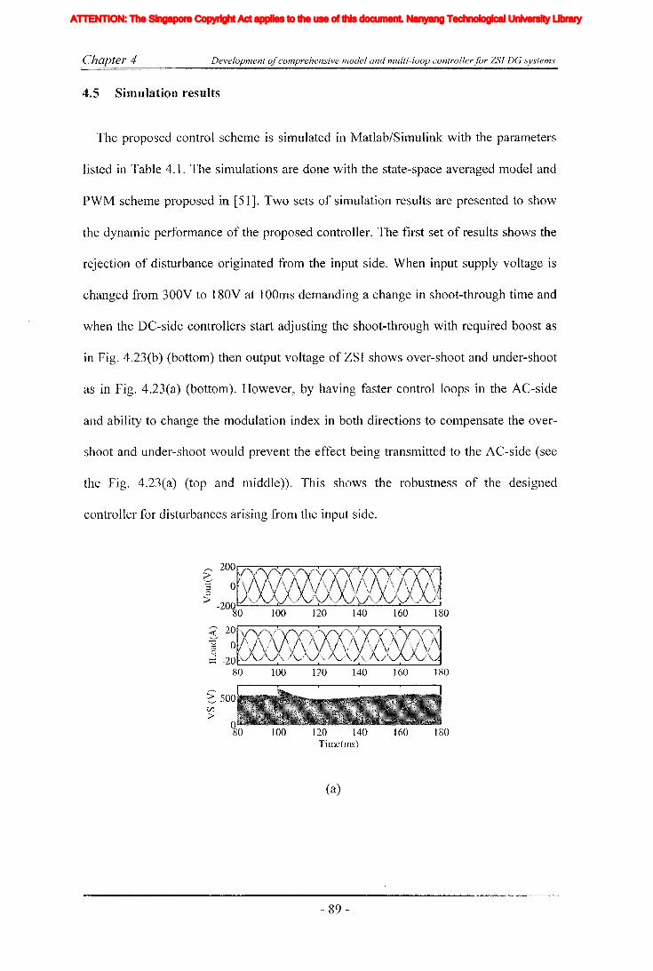
Chapter 4 Development ofcomprehensive model and multi-loop controller for ZSI DG systems
4.5 Simulation results
The proposed control scheme is simulated in Matlab/Simulink with the parameters
listed in Table 4.1. The simulations are done with the state-space averaged model and
PWM scheme proposed in [51]. Two sets of simulation results are presented to show
the dynamic performance of the proposed controller. The first set of results shows the
rejection of disturbance originated from the input side. When input supply voltage is
changed from 300V to 180V at lOOms demanding a change in shoot-through time and
when the DC-side controllers start adjusting the shoot-through with required boost as
in Fig. 4.23(b) (bottom) then output voltage of ZSI shows over-shoot and under-shoot
as in Fig. 4.23(a) (bottom). However, by having faster control loops in the AC-side
and ability to change the modulation index in both directions to compensate the over-
shoot and under-shoot would prevent the effect being transmitted to the AC-side (see
the Fig. 4.23(a) (top and middle)). This shows the robustness of the designed
controller for disturbances arising from the input side.
~200
::l 00
> -20080 100 120 140 160 180
~:0ro0
d80 100 120 140 160 180
~ 500(j')
>100 120 140 160 180
Time(ms)
(a)
- 89 -
Iiq
Iod
Ioq
I odq
I max
1,Ie, Ici,Ic2IDC
IL_m
I MPP
IpvI scITHD
IzI Zn
lap*lap
Ia,Ip,IoIa *, Ip*,10*
Iah,Iphlin
12n
I;
afJ axis currentafJ axis reference currentafJO axis current componentsafJO axis reference current componentsafJ axis harmonic current componentsNeutral current of inverter 1Neutral current of inverter 2Zero sequence reference current
Average Z-source inductor currentPerturbed Z-source inductor current
Perturbed load currentConstantGain factor of fifth harmonics filterGain factor of seventh harmonics filterGain factor of eleventh harmonics filterDC side controller proportional gain of PI controllerDC side controller integral gain of PI controllerGain of the inverterIntegral gain of PI controller in current controllerGain of the hth resonance filterProportional gain of AC side inner loop controllerProportional gain of PI controller in current controllerProportional gain of zero sequence resonance controllerIntegral gain of the resonance controllerIntegral gain of the zero sequence resonance controllerIntegral gain of the hth resonance controllerProportional gain of AC side PI controllerIntegral gain of the AC side PI controllerMultiplying factor for harmonics eliminationDC side filter inductanceLoad inductanceNeutral inductanceGrid inductanceLeakage inductance of transformer
XVII
ATTENTION: The Singapore Copyright Act applies to the use of this document. Nanyang Technological University Library

Chapter 4 Development ofcomprehensive model and multi-loop controllerfor ZSI DG systems
~ 50°1 :-- :~O 100 120 140 160 180
40
~ 20::r 0--20
80 100 120 140 160 1800.5 .......
C/.lQ
~O 100 120 140 160 180Time(ms)
(b)
Fig. 4.23. Simulated results for step change in the input voltage, (a) from top, output
phase voltage across the filter capacitor, load current, and output voltage of impedance
network, (b) fron1 top, voltage across the capacitor, inductor current and shoot-
through duty ratio in the DC-side.
Fig. 4.24 shows the simulated results when a load step change is incurred at lOOms.
The load resistance of the RL load is reduced from 69 to 6.9 n to obtain a current step
change as in Fig. 4.24(a) (middle). This load step change would act as a disturbance to
the DC-side demanding more energy to be transferred into the AC-side causing an
under-shoot in the output voltage of Z-source network as in Fig. 4.24(a) (bottom).
With the employment of strategy mentioned in the previous section, a good transient
performance is achieved. Despite the presence of a small notch, the output voltage
shows a reasonable good disturbance rejection characteristic. With the employment of
closed-loop controllers, the inverter exhibits effective reference tracking and
disturbance rejection properties while startup transients also get attenuated.
- 90 -
Iiq
Iod
Ioq
I odq
I max
1,Ie, Ici,Ic2IDC
IL_m
I MPP
IpvI scITHD
IzI Zn
lap*lap
Ia,Ip,IoIa *, Ip*,10*
Iah,Iphlin
12n
I;
afJ axis currentafJ axis reference currentafJO axis current componentsafJO axis reference current componentsafJ axis harmonic current componentsNeutral current of inverter 1Neutral current of inverter 2Zero sequence reference current
Average Z-source inductor currentPerturbed Z-source inductor current
Perturbed load currentConstantGain factor of fifth harmonics filterGain factor of seventh harmonics filterGain factor of eleventh harmonics filterDC side controller proportional gain of PI controllerDC side controller integral gain of PI controllerGain of the inverterIntegral gain of PI controller in current controllerGain of the hth resonance filterProportional gain of AC side inner loop controllerProportional gain of PI controller in current controllerProportional gain of zero sequence resonance controllerIntegral gain of the resonance controllerIntegral gain of the zero sequence resonance controllerIntegral gain of the hth resonance controllerProportional gain of AC side PI controllerIntegral gain of the AC side PI controllerMultiplying factor for harmonics eliminationDC side filter inductanceLoad inductanceNeutral inductanceGrid inductanceLeakage inductance of transformer
XVII
ATTENTION: The Singapore Copyright Act applies to the use of this document. Nanyang Technological University Library

Chapter 4 Development ofcomprehensive model and multi-loop controller/or ZSI DG systems
>'':;:f0::j
0> -200
80 100 120 140 160 180,.,-... 20<C;:0 0C\i0
d -2080 100 120 140 160 180
>' 500"---'CI'J>
100 120 140 160 180Time(ms)
(a)
~ 50] :~:
80 100 120 140 160 18030
~ 20"---' 10d 0
-1080 100 120 140 160 180
0.4
Q 0.2
~o 100 120 140 160 180Time(rns)
(b)
Fig. 4.24. Simulated results for step change in the load current, (a) from top, output
phase voltage across the filter capacitor, load current, and output voltage of impedance
network, (b) from top, voltage across the capacitor, inductor current and shoot-through
duty ratio in the DC-side
- 91 -
Iiq
Iod
Ioq
I odq
I max
1,Ie, Ici,Ic2IDC
IL_m
I MPP
IpvI scITHD
IzI Zn
lap*lap
Ia,Ip,IoIa *, Ip*,10*
Iah,Iphlin
12n
I;
afJ axis currentafJ axis reference currentafJO axis current componentsafJO axis reference current componentsafJ axis harmonic current componentsNeutral current of inverter 1Neutral current of inverter 2Zero sequence reference current
Average Z-source inductor currentPerturbed Z-source inductor current
Perturbed load currentConstantGain factor of fifth harmonics filterGain factor of seventh harmonics filterGain factor of eleventh harmonics filterDC side controller proportional gain of PI controllerDC side controller integral gain of PI controllerGain of the inverterIntegral gain of PI controller in current controllerGain of the hth resonance filterProportional gain of AC side inner loop controllerProportional gain of PI controller in current controllerProportional gain of zero sequence resonance controllerIntegral gain of the resonance controllerIntegral gain of the zero sequence resonance controllerIntegral gain of the hth resonance controllerProportional gain of AC side PI controllerIntegral gain of the AC side PI controllerMultiplying factor for harmonics eliminationDC side filter inductanceLoad inductanceNeutral inductanceGrid inductanceLeakage inductance of transformer
XVII
ATTENTION: The Singapore Copyright Act applies to the use of this document. Nanyang Technological University Library
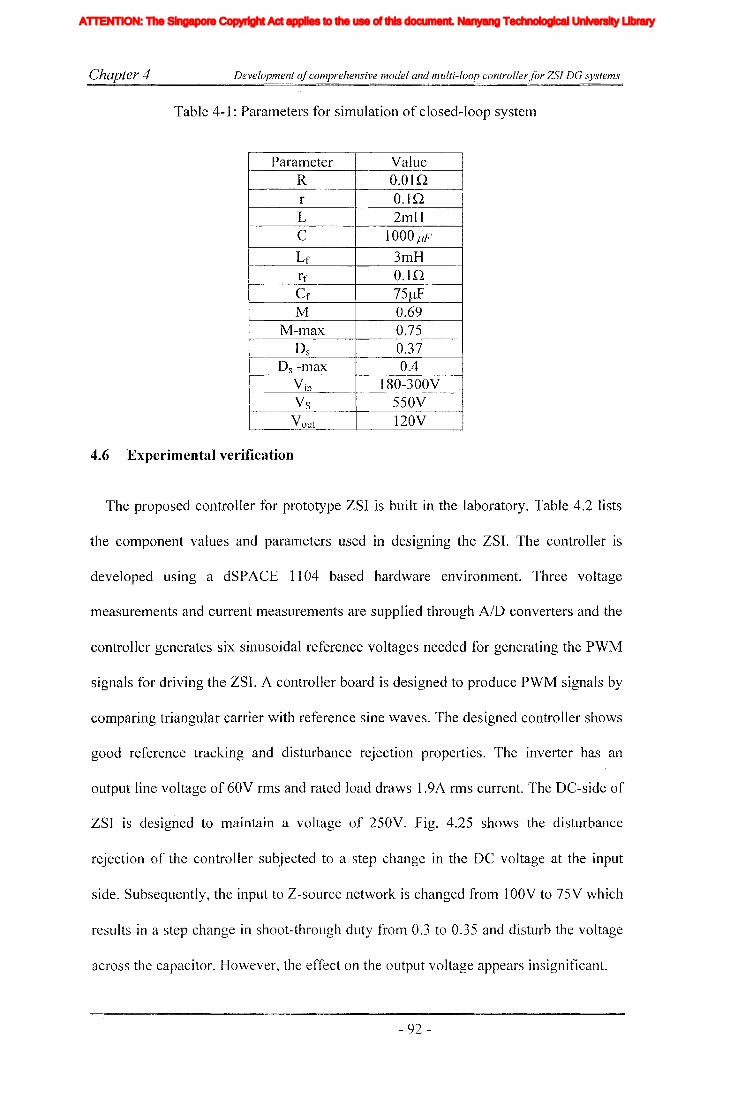
Chapter 4 Development ofcomprehensive model and multi-loop controller for ZSJ DG systems
Table 4-1: Parameters for simulation of closed-loop system
Parameter YalueR O.Olnr O.lQL 2mHC 1000 J-lF
Lf 3mHrf O.lnCf 75f.lFM 0.69
M-max 0.75Ds 0.37
Ds -max 0.4Yin 180-300YVs 550VVout 120V
4.6 Experimental verification
The proposed controller for prototype ZSI is built in the laboratory. Table 4.2 lists
the component values and parameters used in designing the ZSI. The controller is
developed using a dSPACE 1104 based hardware environment. Three voltage
measurelnents and current measurenlents are supplied through AID converters and the
controller generates six sinusoidal reference voltages needed for generating the PWM
signals for driving the ZSI. A controller board is designed to produce PWM signals by
comparing triangular carrier with reference sine waves. The designed controller shows
good reference tracking and disturbance rejection properties. The inverter has an
output line voltage of 60V rms and rated load draws 1.9A rms current. The DC-side of
ZSI is designed to maintain a voltage of 250V. Fig. 4.25 shows the disturbance
rejection of the controller subjected to a step change in the DC voltage at the input
side. Subsequently, the input to Z-source network is changed from 1OOV to 75V which
results in a step change in shoot-through duty from 0.3 to 0.35 and disturb the voltage
across the capacitor. However, the effect on the output voltage appears insignificant.
- 92 -
Iiq
Iod
Ioq
I odq
I max
1,Ie, Ici,Ic2IDC
IL_m
I MPP
IpvI scITHD
IzI Zn
lap*lap
Ia,Ip,IoIa *, Ip*,10*
Iah,Iphlin
12n
I;
afJ axis currentafJ axis reference currentafJO axis current componentsafJO axis reference current componentsafJ axis harmonic current componentsNeutral current of inverter 1Neutral current of inverter 2Zero sequence reference current
Average Z-source inductor currentPerturbed Z-source inductor current
Perturbed load currentConstantGain factor of fifth harmonics filterGain factor of seventh harmonics filterGain factor of eleventh harmonics filterDC side controller proportional gain of PI controllerDC side controller integral gain of PI controllerGain of the inverterIntegral gain of PI controller in current controllerGain of the hth resonance filterProportional gain of AC side inner loop controllerProportional gain of PI controller in current controllerProportional gain of zero sequence resonance controllerIntegral gain of the resonance controllerIntegral gain of the zero sequence resonance controllerIntegral gain of the hth resonance controllerProportional gain of AC side PI controllerIntegral gain of the AC side PI controllerMultiplying factor for harmonics eliminationDC side filter inductanceLoad inductanceNeutral inductanceGrid inductanceLeakage inductance of transformer
XVII
ATTENTION: The Singapore Copyright Act applies to the use of this document. Nanyang Technological University Library

Chapter 4
~u
>
<3>
Development ofcomprehensive model and multi-loop controllerfor ZSJ DG systems
Fig. 4.25. The response of ZSI output voltage subjected to step change in input
voltage, voltage across Z-source capacitor (Ve) (20 V/div), output voltage (VauI)
(50V/div)
Fig. 4.26 shows the inductor current variation followed by the step change and it
can be observed that the inductor current recovers and settles down to the/ new state.
Fig. 4.27 shows the step change in the AC load current in the system. The current is
changed from O.4A rms to 1.9A rms. Fig. 4.28 shows the output voltage waveforms
due to the current disturbance. Although presence of a little voltage spike is evident
due to the switching, it decays down very fast. Fig. 4.29 shows the DC-side response
and the load change has a minimal effect on the capacitor voltage.
~o
>
10ms~
Time (ms)
Fig. 4.26. Response of Z-source impedance network subjected to input voltage step
change, voltage across Z-source capacitor (Ve) (20 V/div), Z-source inductor
current(IL) 3 (A/div)
- 93 -
Iiq
Iod
Ioq
I odq
I max
1,Ie, Ici,Ic2IDC
IL_m
I MPP
IpvI scITHD
IzI Zn
lap*lap
Ia,Ip,IoIa *, Ip*,10*
Iah,Iphlin
12n
I;
afJ axis currentafJ axis reference currentafJO axis current componentsafJO axis reference current componentsafJ axis harmonic current componentsNeutral current of inverter 1Neutral current of inverter 2Zero sequence reference current
Average Z-source inductor currentPerturbed Z-source inductor current
Perturbed load currentConstantGain factor of fifth harmonics filterGain factor of seventh harmonics filterGain factor of eleventh harmonics filterDC side controller proportional gain of PI controllerDC side controller integral gain of PI controllerGain of the inverterIntegral gain of PI controller in current controllerGain of the hth resonance filterProportional gain of AC side inner loop controllerProportional gain of PI controller in current controllerProportional gain of zero sequence resonance controllerIntegral gain of the resonance controllerIntegral gain of the zero sequence resonance controllerIntegral gain of the hth resonance controllerProportional gain of AC side PI controllerIntegral gain of the AC side PI controllerMultiplying factor for harmonics eliminationDC side filter inductanceLoad inductanceNeutral inductanceGrid inductanceLeakage inductance of transformer
XVII
ATTENTION: The Singapore Copyright Act applies to the use of this document. Nanyang Technological University Library

Chapter 4
'0(1Jo
...I
Development ofcomprehensive model and multi-loop controller for ZSI DG systems
Time (ms)
Fig. 4.27. Load current (ILoad) subjected to a load step change (1 A/div)
Time (ms)
Fig. 4.28. Output voltage variation subjected to a load step change (60 V/div)
Time (ms)
Fig. 4.29. Response of Z-source impedance network subjected to a load step change,
voltage across the capacitor (30 V/div) and inductor current (2.5 A/div)
- 94-
Iiq
Iod
Ioq
I odq
I max
1,Ie, Ici,Ic2IDC
IL_m
I MPP
IpvI scITHD
IzI Zn
lap*lap
Ia,Ip,IoIa *, Ip*,10*
Iah,Iphlin
12n
I;
afJ axis currentafJ axis reference currentafJO axis current componentsafJO axis reference current componentsafJ axis harmonic current componentsNeutral current of inverter 1Neutral current of inverter 2Zero sequence reference current
Average Z-source inductor currentPerturbed Z-source inductor current
Perturbed load currentConstantGain factor of fifth harmonics filterGain factor of seventh harmonics filterGain factor of eleventh harmonics filterDC side controller proportional gain of PI controllerDC side controller integral gain of PI controllerGain of the inverterIntegral gain of PI controller in current controllerGain of the hth resonance filterProportional gain of AC side inner loop controllerProportional gain of PI controller in current controllerProportional gain of zero sequence resonance controllerIntegral gain of the resonance controllerIntegral gain of the zero sequence resonance controllerIntegral gain of the hth resonance controllerProportional gain of AC side PI controllerIntegral gain of the AC side PI controllerMultiplying factor for harmonics eliminationDC side filter inductanceLoad inductanceNeutral inductanceGrid inductanceLeakage inductance of transformer
XVII
ATTENTION: The Singapore Copyright Act applies to the use of this document. Nanyang Technological University Library

Chapter 4
4.7 Discussion
Development ofcomprehensive model and multi-loop controller for ZSl DG systems
Table 4-2: Parameters for the experimental set-up
Parameter ValueR 0.0630r 0.160L 5mHC 600flFLf 2mHrf 0.230
Cf 15,uF
M 0.60M-max 0.75
Ds 0.3Ds-max 0.4
In this chapter, a multi-loop controller for ZSI is developed for DG applications.
Towards that end, the ZSI is modeled with state space averaging technique and
necessary transfer functions are also derived. The derived transfer functions prove the
presence of RHHP and non-minimum phase characteristics in the DC-side. In addition
open loop and closed-loop simulations it has been observed that there is a possibility
of the DC-side effects being transferred into the AC-side. These characteristics have
complicated the controller designing. However, these are overcome with proper
selection of parameters and with the adoption of a novel cushioning technique for the
modulation index.
AC and DC sides are considered as separate units and controllers are designed to
achieve a good voltage regulation and disturbance rejection. The AC-side controllers
are designed in synchronous reference [ratTIe with inner current and outer voltage
loops. A proportional controller is employed in the inner current loop while a PI
controller is used in the outer voltage loop to remove the steady state error. However,
- 95 -
Iiq
Iod
Ioq
I odq
I max
1,Ie, Ici,Ic2IDC
IL_m
I MPP
IpvI scITHD
IzI Zn
lap*lap
Ia,Ip,IoIa *, Ip*,10*
Iah,Iphlin
12n
I;
afJ axis currentafJ axis reference currentafJO axis current componentsafJO axis reference current componentsafJ axis harmonic current componentsNeutral current of inverter 1Neutral current of inverter 2Zero sequence reference current
Average Z-source inductor currentPerturbed Z-source inductor current
Perturbed load currentConstantGain factor of fifth harmonics filterGain factor of seventh harmonics filterGain factor of eleventh harmonics filterDC side controller proportional gain of PI controllerDC side controller integral gain of PI controllerGain of the inverterIntegral gain of PI controller in current controllerGain of the hth resonance filterProportional gain of AC side inner loop controllerProportional gain of PI controller in current controllerProportional gain of zero sequence resonance controllerIntegral gain of the resonance controllerIntegral gain of the zero sequence resonance controllerIntegral gain of the hth resonance controllerProportional gain of AC side PI controllerIntegral gain of the AC side PI controllerMultiplying factor for harmonics eliminationDC side filter inductanceLoad inductanceNeutral inductanceGrid inductanceLeakage inductance of transformer
XVII
ATTENTION: The Singapore Copyright Act applies to the use of this document. Nanyang Technological University Library

Chapter 4 Development ofcomprehensive model and multi-loop controller for ZSJ DC systems
the presence of RHHP zero and pulsating nature of Vs in the DC-side complicates the
DC-side controller. This complication is overcome by having appropriate inner current
and outer voltage loops. Simulation and experimental results show good reference
tracking and disturbance rejection for disturbances originated from both the input and
the output sides. This proves the effective performance of proposed multi-loop
controller.
- 96-
Iiq
Iod
Ioq
I odq
I max
1,Ie, Ici,Ic2IDC
IL_m
I MPP
IpvI scITHD
IzI Zn
lap*lap
Ia,Ip,IoIa *, Ip*,10*
Iah,Iphlin
12n
I;
afJ axis currentafJ axis reference currentafJO axis current componentsafJO axis reference current componentsafJ axis harmonic current componentsNeutral current of inverter 1Neutral current of inverter 2Zero sequence reference current
Average Z-source inductor currentPerturbed Z-source inductor current
Perturbed load currentConstantGain factor of fifth harmonics filterGain factor of seventh harmonics filterGain factor of eleventh harmonics filterDC side controller proportional gain of PI controllerDC side controller integral gain of PI controllerGain of the inverterIntegral gain of PI controller in current controllerGain of the hth resonance filterProportional gain of AC side inner loop controllerProportional gain of PI controller in current controllerProportional gain of zero sequence resonance controllerIntegral gain of the resonance controllerIntegral gain of the zero sequence resonance controllerIntegral gain of the hth resonance controllerProportional gain of AC side PI controllerIntegral gain of the AC side PI controllerMultiplying factor for harmonics eliminationDC side filter inductanceLoad inductanceNeutral inductanceGrid inductanceLeakage inductance of transformer
XVII
ATTENTION: The Singapore Copyright Act applies to the use of this document. Nanyang Technological University Library

Chapter 5 Modulation and control ofthree phase paralleled ZSls jor distributed generation applications
Chapter 5
Modulation and control of three phase paralleled ZSIs
for distributed generation applications
5.1 Introduction
In previous chapters the emphasis is given to study the ZSI as a DO interface. A
mathematical model is obtained and closed loop controllers are designed to interface a
DO source into a stand-alone type load. Howeyer, if the DO sources have larger
capacity and if the system is kept isolated from the grid, source would be operating at
suboptimal operating point. Therefore, connecting it to the grid would be more
appropriate and this would enhance the reliability of the supply to locally connected
load. However, the controllers need to be designed to operate in both grid connected
and islanding mode. This allows the continuous powering of sensitive load and
protection of the load from possible grid faults.
Many industrial systems demand a reliable power supply and one way to increase
the reliability is to increase the number of sources. Another way to increase the
reliability is to have parallel inverters and this would increase the redundancy as well
as the maintainability of the inverters. This is especially useful with high capacity
generation where a single power module is not large enough to handle the capacity.
Although it is possible to increase the capacity with paralleling devices, failure of one
device tend to damage the others too whereas paralleled inverters can be operated
independently. The paralleled inverters can be found in multi-transformer and Inultiple
inverter systems or multiple carrier ITIulti inverter systems. They are frequently used to
- 97 -
Iiq
Iod
Ioq
I odq
I max
1,Ie, Ici,Ic2IDC
IL_m
I MPP
IpvI scITHD
IzI Zn
lap*lap
Ia,Ip,IoIa *, Ip*,10*
Iah,Iphlin
12n
I;
afJ axis currentafJ axis reference currentafJO axis current componentsafJO axis reference current componentsafJ axis harmonic current componentsNeutral current of inverter 1Neutral current of inverter 2Zero sequence reference current
Average Z-source inductor currentPerturbed Z-source inductor current
Perturbed load currentConstantGain factor of fifth harmonics filterGain factor of seventh harmonics filterGain factor of eleventh harmonics filterDC side controller proportional gain of PI controllerDC side controller integral gain of PI controllerGain of the inverterIntegral gain of PI controller in current controllerGain of the hth resonance filterProportional gain of AC side inner loop controllerProportional gain of PI controller in current controllerProportional gain of zero sequence resonance controllerIntegral gain of the resonance controllerIntegral gain of the zero sequence resonance controllerIntegral gain of the hth resonance controllerProportional gain of AC side PI controllerIntegral gain of the AC side PI controllerMultiplying factor for harmonics eliminationDC side filter inductanceLoad inductanceNeutral inductanceGrid inductanceLeakage inductance of transformer
XVII
ATTENTION: The Singapore Copyright Act applies to the use of this document. Nanyang Technological University Library
Chapter 5 Modulation and control ofthree phase paralleled ZSls for distributed generation applications
reduce the PWM switching frequency and resulting harmonics [47]. Paralleled
inverters can be built in numerous ways. First and the most obvious way is to have
independent inverters with separate DC sources [96] and the other possibility is to
connect the inverters into a common DC source [97]. First method is common as it is
simple. However, it requires more than one power source. In the context of ZSI, this
method requires more than one independent Z-source impedance network. However,
in both methods, controlling is known to be difficult due to the presence of current
flow between the inverters. This current can have both low and high frequency
components. The low frequency current is caused by small unbalances, impedance
differences and control interactions in paralleling inverters. The high frequency current
is caused by inverters that have a common DC link and interleaved carriers. This
current is due to the formation of extra current paths in such topologies. This can be
avoided by having isolation transformers. Alternatively, cross link current can be
reduced with the use of common mode coils or coupling inductors, although they are
effective only in medium and high frequency range. Low frequency currents can be
suppressed to a certain extent by having zero sequence controllers in the controlling
loop [98]. These aspects need to be considered in designing modulators and controllers
for paralleled ZSI systems.
This chapter focuses on designing modulation and controllers for parallel connected
Z-sourced inverters that can be used for interfacing fuel cells, solar celJs or variable
speed wind generators connected with simple diode rectifiers into the utility grid and
also to provide an uninterrupted supply to a sensitive load. The controllers are
designed in multi-loop configuration. The outer level controllers are designed to
deliver constant active and reactive power in the grid connected mode. Each inverter
consists of a current controller in the AC-side and it is driven by a COlnmon power
- 98 -
Iiq
Iod
Ioq
I odq
I max
1,Ie, Ici,Ic2IDC
IL_m
I MPP
IpvI scITHD
IzI Zn
lap*lap
Ia,Ip,IoIa *, Ip*,10*
Iah,Iphlin
12n
I;
afJ axis currentafJ axis reference currentafJO axis current componentsafJO axis reference current componentsafJ axis harmonic current componentsNeutral current of inverter 1Neutral current of inverter 2Zero sequence reference current
Average Z-source inductor currentPerturbed Z-source inductor current
Perturbed load currentConstantGain factor of fifth harmonics filterGain factor of seventh harmonics filterGain factor of eleventh harmonics filterDC side controller proportional gain of PI controllerDC side controller integral gain of PI controllerGain of the inverterIntegral gain of PI controller in current controllerGain of the hth resonance filterProportional gain of AC side inner loop controllerProportional gain of PI controller in current controllerProportional gain of zero sequence resonance controllerIntegral gain of the resonance controllerIntegral gain of the zero sequence resonance controllerIntegral gain of the hth resonance controllerProportional gain of AC side PI controllerIntegral gain of the AC side PI controllerMultiplying factor for harmonics eliminationDC side filter inductanceLoad inductanceNeutral inductanceGrid inductanceLeakage inductance of transformer
XVII
ATTENTION: The Singapore Copyright Act applies to the use of this document. Nanyang Technological University Library

Chapter 5 Modulation and control ofthree phase paralleled ZSls for distributed generation applications
controlling loop or a voltage controlling loop. In the islanding mode, controllers track
the reference voltage. This is achieved using a common voltage controller that uses the
measured voltage at the point of common coupling (PCC) for controlling current in the
inner loop for faster response. However, with wider voltage variations in renewable
sources, the DC-side controllers are designed to maintain a constant voltage to the
inverter bridge. Steady state and transient performances of the designed controllers are
verified with simulations obtained using Matlab/Simulink with SimCoupler interfacing
the circuit model developed in PSIM. Experimental results are also obtained using a
laboratory prototype.
5.2 Paralleled ZSI topology
Fig. 5.1 shows the circuit diagram of proposed paralleled ZSI, where two inverter
bridges are connected to a common Z-source impedance network that consists of two
capacitors and two inductors connected in X shape. The use of a series diode allows
the boosting of voltage and prevents the reverse current flow. In the AC-side, each
phase of the inverter arm is connected with a filter inductor and both the inverters are
connected to the grid at the PCC. LI, Lg, rl, and rg represent the filter inductance, grid
inductance, filter resistance and grid resistance respectively. Moreover, a three phase
load is connected to the DG system at the PCC. A three phase static switch is
connected between the grid and DG system. When there is a grid fault, the systelTI is
disconnected from the grid and operates in islanding mode providing desired voltage
to the sensitive load. Irrespective of the operational mode, i.e. the grid-connected or
islanded JTIodes, the real and reactive power components of the two inverters are
correspondingly equal. Usually, when interconnecting the inverters into the grid, larger
values of inductors is preferred to suppress the resultant ripple current. However, this
- 99 -
Iiq
Iod
Ioq
I odq
I max
1,Ie, Ici,Ic2IDC
IL_m
I MPP
IpvI scITHD
IzI Zn
lap*lap
Ia,Ip,IoIa *, Ip*,10*
Iah,Iphlin
12n
I;
afJ axis currentafJ axis reference currentafJO axis current componentsafJO axis reference current componentsafJ axis harmonic current componentsNeutral current of inverter 1Neutral current of inverter 2Zero sequence reference current
Average Z-source inductor currentPerturbed Z-source inductor current
Perturbed load currentConstantGain factor of fifth harmonics filterGain factor of seventh harmonics filterGain factor of eleventh harmonics filterDC side controller proportional gain of PI controllerDC side controller integral gain of PI controllerGain of the inverterIntegral gain of PI controller in current controllerGain of the hth resonance filterProportional gain of AC side inner loop controllerProportional gain of PI controller in current controllerProportional gain of zero sequence resonance controllerIntegral gain of the resonance controllerIntegral gain of the zero sequence resonance controllerIntegral gain of the hth resonance controllerProportional gain of AC side PI controllerIntegral gain of the AC side PI controllerMultiplying factor for harmonics eliminationDC side filter inductanceLoad inductanceNeutral inductanceGrid inductanceLeakage inductance of transformer
XVII
ATTENTION: The Singapore Copyright Act applies to the use of this document. Nanyang Technological University Library
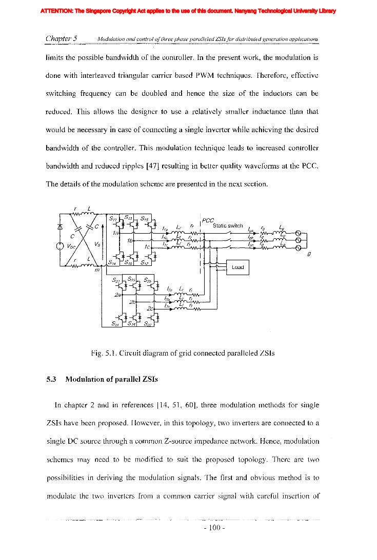
Chapter 5 Modulation and control ofthree phase paralleled ZSls for distributed generation applications
limits the possible bandwidth of the controller. In the present work, the lTIodulation is
done with interleaved triangular carrier based PWM techniques. Therefore, effective
switching frequency can be doubled and hence the size of the inductors can be
reduced. This allows the designer to use a relatively smaller inductance than that
would be necessary in case of connecting a single inverter while achieving the desired
bandwidth of the controller. This modulation technique leads to increased controller
bandwidth and reduced ripples [47] resulting in better quality waveforms at the PCC.
The details of the modulation scheme are presented in the next section.
r L
m
IpeeI Static switch /Igga
b
: r. L
'--'1IV\r-+-'J'-.....----r ..--....;;..lgC..;-~g
Fig. 5.1. Circuit diagram of grid connected paralleled ZSIs
5.3 Modulation of parallel ZSIs
In chapter 2 and in references [14, 51, 60], three modulation n1ethods for single
ZSIs have been proposed. However, in this topology, two inverters are connected to a
single DC source through a COlTIlTIOn Z-source impedance network. Hence, n1odulation
schemes may need to be modified to suit the proposed topology. There are two
possibilities in deriving the modulation signals. The first and obvious method is to
lTIodulate the two inverters frolll a common carrier signal with careful insertion of
- 100 -
Iiq
Iod
Ioq
I odq
I max
1,Ie, Ici,Ic2IDC
IL_m
I MPP
IpvI scITHD
IzI Zn
lap*lap
Ia,Ip,IoIa *, Ip*,10*
Iah,Iphlin
12n
I;
afJ axis currentafJ axis reference currentafJO axis current componentsafJO axis reference current componentsafJ axis harmonic current componentsNeutral current of inverter 1Neutral current of inverter 2Zero sequence reference current
Average Z-source inductor currentPerturbed Z-source inductor current
Perturbed load currentConstantGain factor of fifth harmonics filterGain factor of seventh harmonics filterGain factor of eleventh harmonics filterDC side controller proportional gain of PI controllerDC side controller integral gain of PI controllerGain of the inverterIntegral gain of PI controller in current controllerGain of the hth resonance filterProportional gain of AC side inner loop controllerProportional gain of PI controller in current controllerProportional gain of zero sequence resonance controllerIntegral gain of the resonance controllerIntegral gain of the zero sequence resonance controllerIntegral gain of the hth resonance controllerProportional gain of AC side PI controllerIntegral gain of the AC side PI controllerMultiplying factor for harmonics eliminationDC side filter inductanceLoad inductanceNeutral inductanceGrid inductanceLeakage inductance of transformer
XVII
ATTENTION: The Singapore Copyright Act applies to the use of this document. Nanyang Technological University Library

C"hapter 5 Modulation and control ofthree phase paralleled ZSls for distributed generation applications
shoot-through time with simple boost or minimum switching [14, 51] methods
proposed for the single ZSI. This could work well with both the methods but this may
need large filter inductors. However, by adopting the minimum switching method,
there is a possibility of occurrence of over boost conditions if the shoot-through
intervals of the two inverters do not coincide exactly. The second possibility is to use
two interleaved carriers in realizing PWM signals. This method has been commonly
used with many paralleled inverter structures [47] and this produces a resultant system
output with three levels with improved output voltage quality and reduced ripple
current. However, with this method, both inverters go into null states resulting in
additional conduction paths as discussed before. Moreover, in modulating the ZSIs,
shoot-through should be included without disturbing the functionality of the inverters
while maintaining the correct volt-second balance. Unlike the common carrier method,
when the interleaved carrier signals are used, the modulation method proposed in [51]
cannot be employed. As the shoot-through intervals of two inverters do not coincide
all the time, this could lead to distortion in the volt-second average and over boost.
Therefore, in this work, a siInple boost strategy is employed. Fig. 5.2 shows the
modulation signals generated for the two inverters. There are five reference signals
used and the top and bottom most reference signals are straight lines providing the
reference for the shoot-through interval and other three signals are AC-side sinusoidal
reference signals. Switching signals are labeled with Sij where subscript i=1, 2 is used
to indicate the inverter and subscript j=l, 2, 3, 4, 5 and 6 is used to indicate the number
of the switch. COlllplying with the general representation of inverter states when a
switch is in ON state it is represented with" 1" and when it is off it is represented with
"0". For exaillple SII=l indicates the switching signal of the top switch of phase "a" of
the inverter 1 or the switch is in ON state. Generally switching states of a three phase
- 101 -
Iiq
Iod
Ioq
I odq
I max
1,Ie, Ici,Ic2IDC
IL_m
I MPP
IpvI scITHD
IzI Zn
lap*lap
Ia,Ip,IoIa *, Ip*,10*
Iah,Iphlin
12n
I;
afJ axis currentafJ axis reference currentafJO axis current componentsafJO axis reference current componentsafJ axis harmonic current componentsNeutral current of inverter 1Neutral current of inverter 2Zero sequence reference current
Average Z-source inductor currentPerturbed Z-source inductor current
Perturbed load currentConstantGain factor of fifth harmonics filterGain factor of seventh harmonics filterGain factor of eleventh harmonics filterDC side controller proportional gain of PI controllerDC side controller integral gain of PI controllerGain of the inverterIntegral gain of PI controller in current controllerGain of the hth resonance filterProportional gain of AC side inner loop controllerProportional gain of PI controller in current controllerProportional gain of zero sequence resonance controllerIntegral gain of the resonance controllerIntegral gain of the zero sequence resonance controllerIntegral gain of the hth resonance controllerProportional gain of AC side PI controllerIntegral gain of the AC side PI controllerMultiplying factor for harmonics eliminationDC side filter inductanceLoad inductanceNeutral inductanceGrid inductanceLeakage inductance of transformer
XVII
ATTENTION: The Singapore Copyright Act applies to the use of this document. Nanyang Technological University Library

Chapter 5 Modulation and control ofthree phase paralleled ZSlsfor distributed generation applications
VSI indicated with the status of switches Sil, Si2 and Si3. That is state "111" means all
top switches of particular inverter is in ON state and corresponding bottom switch Si4,
Si6 and Sa are OFF state and inverter goes in to one of the two null states. These rules
apply when the inverters are in both active and null states. However, with Z-source
inverter during shoot-through state both the switches in an arm are ON. This is
represented with "X". As indicated in dotted box of Fig. 5.2. With two interleaved
carrier signals, when one inverter reaches the null state with (000), the other has (111).
The inverters reach the shoot through state as carrier signals cross the shoot-through
references. When one inverter goes into (000) state, all the bottom switches are tumed
on and to provide the shoot-through at least one of the top switches also needs to be
switched on. Silnilarly, when the inverter goes into (Ill) state, all the top switches are
turned-on while at least one of the bottom switches needs to be switched on to provide
shoot through. As it is needless to apply shoot-through in all three arms
simultaneously, it would be better if shoot-through is allowed to alternate among arnlS
to avoid the over-stressing of a particular switch. This switching signal conditioning is
carried out with a field programmable logic device in the practical prototype.
Furthermore, the simultaneous employment of shoot-through intervals in both
inverters allows them to operate independently thus facilitating paralleling of
additional Inodules for further expansions and thereby to increase the capacity and the
redundancy. Also, inverters share the shoot-through current thus reducing the
possibility of over-stressing of a particular inverter. In this context, the shoot-through
is inserted with the use of top and bottom reference signals, and thereby spreading
switching stress among all the switches equally. Derived switching signals are shown
in bottom of Fig. 5.2. The shoot-through periods are inserted in both inverters
simultaneously and when the inverters operate in this sector they. goes into (X 11) or
- 102 -
Iiq
Iod
Ioq
I odq
I max
1,Ie, Ici,Ic2IDC
IL_m
I MPP
IpvI scITHD
IzI Zn
lap*lap
Ia,Ip,IoIa *, Ip*,10*
Iah,Iphlin
12n
I;
afJ axis currentafJ axis reference currentafJO axis current componentsafJO axis reference current componentsafJ axis harmonic current componentsNeutral current of inverter 1Neutral current of inverter 2Zero sequence reference current
Average Z-source inductor currentPerturbed Z-source inductor current
Perturbed load currentConstantGain factor of fifth harmonics filterGain factor of seventh harmonics filterGain factor of eleventh harmonics filterDC side controller proportional gain of PI controllerDC side controller integral gain of PI controllerGain of the inverterIntegral gain of PI controller in current controllerGain of the hth resonance filterProportional gain of AC side inner loop controllerProportional gain of PI controller in current controllerProportional gain of zero sequence resonance controllerIntegral gain of the resonance controllerIntegral gain of the zero sequence resonance controllerIntegral gain of the hth resonance controllerProportional gain of AC side PI controllerIntegral gain of the AC side PI controllerMultiplying factor for harmonics eliminationDC side filter inductanceLoad inductanceNeutral inductanceGrid inductanceLeakage inductance of transformer
XVII
ATTENTION: The Singapore Copyright Act applies to the use of this document. Nanyang Technological University Library

Chapter 5 Modulation and control ofthree phase paralleled ZSls for distributed generation applications
(ODX). The sector is identified from the maximum and minimum magnitudes of the
AC-side reference signals at any given time.
SH1-~~"':'-~"':"':-~~~-~---:'''':'-+--T~--':''--:--~-r--~~-:--~~-r-
a
b
c
!, r---l !
Fig. 5.2. Modulation and switching signals
5.4 System modeling and Controller designing
When designing controllers for DO systems, they should meet the interconnection
and power quality standards like IEEE 1547. Utility companies control the system
frequency and the grid voltage. Therefore, controllers of small DG sources should
preferably be designed to control the current or the power delivered to the grid. Also,
proposed controllers should continue to function even when the system undergoes a
small duration fault. Effectively, the controllers are expected to deliver balanced
currents under disturbed grid voltage conditions while supplying uninterrupted voltage
to the sensitive load.
Presently, there are a few controlling techniques applicable for grid connected
parallel inverter systems, Iike master-slave control, active-reactive power control and
- 103 -
Iiq
Iod
Ioq
I odq
I max
1,Ie, Ici,Ic2IDC
IL_m
I MPP
IpvI scITHD
IzI Zn
lap*lap
Ia,Ip,IoIa *, Ip*,10*
Iah,Iphlin
12n
I;
afJ axis currentafJ axis reference currentafJO axis current componentsafJO axis reference current componentsafJ axis harmonic current componentsNeutral current of inverter 1Neutral current of inverter 2Zero sequence reference current
Average Z-source inductor currentPerturbed Z-source inductor current
Perturbed load currentConstantGain factor of fifth harmonics filterGain factor of seventh harmonics filterGain factor of eleventh harmonics filterDC side controller proportional gain of PI controllerDC side controller integral gain of PI controllerGain of the inverterIntegral gain of PI controller in current controllerGain of the hth resonance filterProportional gain of AC side inner loop controllerProportional gain of PI controller in current controllerProportional gain of zero sequence resonance controllerIntegral gain of the resonance controllerIntegral gain of the zero sequence resonance controllerIntegral gain of the hth resonance controllerProportional gain of AC side PI controllerIntegral gain of the AC side PI controllerMultiplying factor for harmonics eliminationDC side filter inductanceLoad inductanceNeutral inductanceGrid inductanceLeakage inductance of transformer
XVII
ATTENTION: The Singapore Copyright Act applies to the use of this document. Nanyang Technological University Library

Chapter 5 Modulation and control ofthree phase paralleled ZSls for distributed generation applications
conventional droop control [99]. Since each inverter delivers equal amount of power to
the systell1, the inverters have to be driven from a common reference signal, and both
droop and active-reactive power controlling techniques are suitable. However,
application of master-slave type controller would complicate the system due to the
presence of shoot-through states as the shoot-through states need to be inserted in all
the inverter modules to divide the current stress. Furthermore, such a scheme would
inhibit the possibility of expansion of the system. In [100], a parallel inverter system is
proposed in which cross coupling is controlled with a zero sequence controller that
adjusts the null interval to remove the zero sequence component. This method may not
be applicable in the proposed topology as it contains shoot-through states.
L r
m
Seq
Fig. 5.3 Simplified diagram of proposed DG system
(5-1)
In chapter 4 and in reference [18], a comprehensive model for the single ZSI has
been developed and controllers have been designed as two separate subsystems,
namely AC and DC side subsystems. From the dynamic analysis point of view of the
two systelTIS, it has been found that the subsystems have significantly different time
constants. Hence, DC and AC side subsystems can be considered as cascaded slow and
- 104 -
Iiq
Iod
Ioq
I odq
I max
1,Ie, Ici,Ic2IDC
IL_m
I MPP
IpvI scITHD
IzI Zn
lap*lap
Ia,Ip,IoIa *, Ip*,10*
Iah,Iphlin
12n
I;
afJ axis currentafJ axis reference currentafJO axis current componentsafJO axis reference current componentsafJ axis harmonic current componentsNeutral current of inverter 1Neutral current of inverter 2Zero sequence reference current
Average Z-source inductor currentPerturbed Z-source inductor current
Perturbed load currentConstantGain factor of fifth harmonics filterGain factor of seventh harmonics filterGain factor of eleventh harmonics filterDC side controller proportional gain of PI controllerDC side controller integral gain of PI controllerGain of the inverterIntegral gain of PI controller in current controllerGain of the hth resonance filterProportional gain of AC side inner loop controllerProportional gain of PI controller in current controllerProportional gain of zero sequence resonance controllerIntegral gain of the resonance controllerIntegral gain of the zero sequence resonance controllerIntegral gain of the hth resonance controllerProportional gain of AC side PI controllerIntegral gain of the AC side PI controllerMultiplying factor for harmonics eliminationDC side filter inductanceLoad inductanceNeutral inductanceGrid inductanceLeakage inductance of transformer
XVII
ATTENTION: The Singapore Copyright Act applies to the use of this document. Nanyang Technological University Library

Chapter 5 Modulation and control ofthree phase paralleled ZSls for distributed generation applications
fast systems [94]. With this simplification, the controller design for the two
subsystems can be done independently. Fig. 5.3 shows the simplified diagram of the
proposed topology where AC side and DC sides are represented by two separate
circuits. The difference in this topology compared to the previous topology in chapter
4 is that the presence of two inverters, the circulating current in the AC-side and the
coupling of zero sequence components into the DC-side. These issues have to be
addressed in the controller design. Ieq in Fig. 5.3 is described by (5-1) where dia, d ib,
die, d 2a, d 2b and d2e represent average switching duty ratios of two inverters (in this
case it is fair to assume switching frequency is significantly higher than power system
frequency, hence switchings can be represented by an average switching duty ratio). 1z
in Fig. 5.3 is the circulation current. Mainly zero sequence current has two
components low frequency and high frequency component. l-ligh frequency
component is significant with interleaved carrier based modulation methods. Low
frequency circulating currents are resulted from voltage differences in outputs of the
inverters. Unequal component values, differences in control signals and third harmonic
components added in modulation design are also play significant roll. Adopted
controlling method also has a significant influence, droop controlling and master slave
controlling could result in high circulating current whereas active reactive power
controlling would result in least circulation current. In this context when the output
voltage is controlled in islanding mode operation high circulation current would be
present. These aspects need careful consideration in designing the controllers.
- 105 -
Iiq
Iod
Ioq
I odq
I max
1,Ie, Ici,Ic2IDC
IL_m
I MPP
IpvI scITHD
IzI Zn
lap*lap
Ia,Ip,IoIa *, Ip*,10*
Iah,Iphlin
12n
I;
afJ axis currentafJ axis reference currentafJO axis current componentsafJO axis reference current componentsafJ axis harmonic current componentsNeutral current of inverter 1Neutral current of inverter 2Zero sequence reference current
Average Z-source inductor currentPerturbed Z-source inductor current
Perturbed load currentConstantGain factor of fifth harmonics filterGain factor of seventh harmonics filterGain factor of eleventh harmonics filterDC side controller proportional gain of PI controllerDC side controller integral gain of PI controllerGain of the inverterIntegral gain of PI controller in current controllerGain of the hth resonance filterProportional gain of AC side inner loop controllerProportional gain of PI controller in current controllerProportional gain of zero sequence resonance controllerIntegral gain of the resonance controllerIntegral gain of the zero sequence resonance controllerIntegral gain of the hth resonance controllerProportional gain of AC side PI controllerIntegral gain of the AC side PI controllerMultiplying factor for harmonics eliminationDC side filter inductanceLoad inductanceNeutral inductanceGrid inductanceLeakage inductance of transformer
XVII
ATTENTION: The Singapore Copyright Act applies to the use of this document. Nanyang Technological University Library
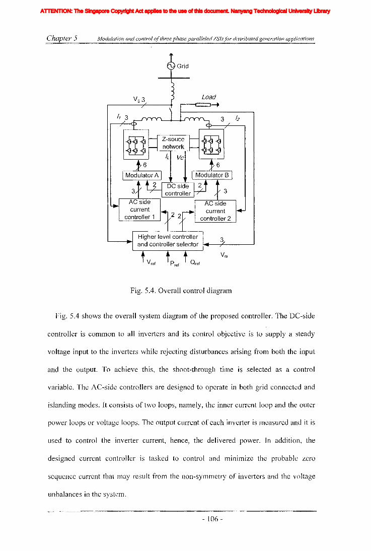
Chapter 5 Modulation and control ofthree phase paralleled ZSls for distributed generation applications
/1 3
Fig. 5.4. Overall control diagram
Fig. 5.4 shows the overall system diagram of the proposed controller. The DC-side
controller is COllllllon to all inverters and its control objective is to supply a steady
voltage input to the inverters while rejecting disturbances arising from both the input
and the output. To achieve this, the shoot-through tillle is selected as a control
variable. The AC-side controllers are designed to operate in both grid connected and
islanding modes. It consists of two loops, namely, the inner current loop and the outer
power loops or voltage loops. The output current of each inverter is measured and it is
used to control the inverter current, hence, the delivered power. In addition, the
designed current controller is tasked to control and minilnize the probable zero
sequence current that may result from the non-symmetry of inverters and the voltage
unbalances in the system.
- 106 -
Iiq
Iod
Ioq
I odq
I max
1,Ie, Ici,Ic2IDC
IL_m
I MPP
IpvI scITHD
IzI Zn
lap*lap
Ia,Ip,IoIa *, Ip*,10*
Iah,Iphlin
12n
I;
afJ axis currentafJ axis reference currentafJO axis current componentsafJO axis reference current componentsafJ axis harmonic current componentsNeutral current of inverter 1Neutral current of inverter 2Zero sequence reference current
Average Z-source inductor currentPerturbed Z-source inductor current
Perturbed load currentConstantGain factor of fifth harmonics filterGain factor of seventh harmonics filterGain factor of eleventh harmonics filterDC side controller proportional gain of PI controllerDC side controller integral gain of PI controllerGain of the inverterIntegral gain of PI controller in current controllerGain of the hth resonance filterProportional gain of AC side inner loop controllerProportional gain of PI controller in current controllerProportional gain of zero sequence resonance controllerIntegral gain of the resonance controllerIntegral gain of the zero sequence resonance controllerIntegral gain of the hth resonance controllerProportional gain of AC side PI controllerIntegral gain of the AC side PI controllerMultiplying factor for harmonics eliminationDC side filter inductanceLoad inductanceNeutral inductanceGrid inductanceLeakage inductance of transformer
XVII
ATTENTION: The Singapore Copyright Act applies to the use of this document. Nanyang Technological University Library
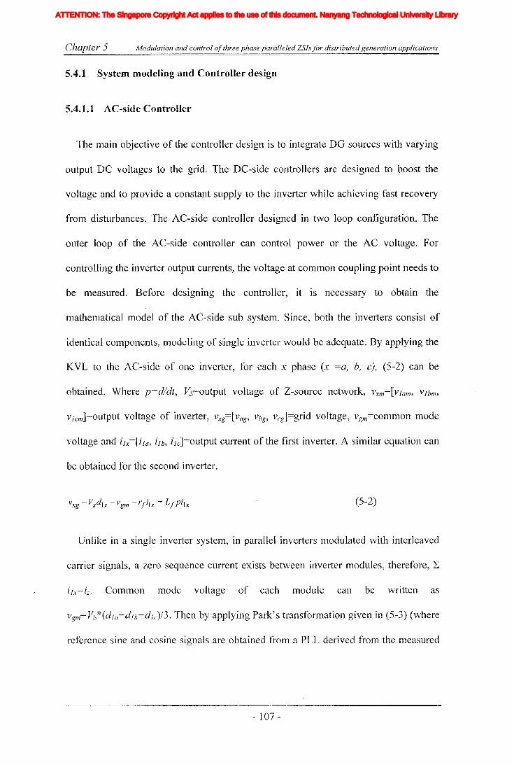
Chapter 5 Modulation and control ofthree phase paralleled ZSIs for distributed generation applications
5.4.1 System modeling and Controller design
5.4.1.1 AC-side Controller
The main objective of the controller design is to integrate DG sources with varying
output DC voltages to the grid. The DC-side controllers are designed to boost the
voltage and to provide a constant supply to the inverter while achieving fast recovery
from disturbances. The AC-side controller designed in two loop configuration. The
outer loop of the AC-side controller can control power or the AC voltage. For
controlling the inverter output currents, the voltage at common coupling point needs to
be measured. Before designing the controller, it is necessary to obtain the
mathematical model of the AC-side sub system. Since, both the inverters consist of
identical components, modeling of single inverter would be adequate. By applying the
KVL to the AC-side of one inverter, for each x phase (x =a, b, c), (5-2) can be
obtained. Where p=d/dt, Vs=output voltage of Z-source network, Vxm=[Vl am, Vlbm,
Vlcm]=output voltage of inverter, vxg=[vag, Vbg, vcg]=grid voltage, vgm=common mode
voltage and ilx=[ila, ilb, ilc]=output current of the first inverter. A similar equation can
be obtained for the second inverter.
(5-2)
Unlike in a single inverter system, in parallel inverters modulated with interleaved
carrier signals, a zero sequence current exists between inverter modules, therefore, L
i1x=iz o COlumon mode voltage of each module can be written as
Vgm=VS*(dla+dlb+dlc)/3. Then by applying Park's transformation given in (5-3) (where
reference sine and cosine signals are obtained from a PLL derived frol11 the measured
- 107 -
Iiq
Iod
Ioq
I odq
I max
1,Ie, Ici,Ic2IDC
IL_m
I MPP
IpvI scITHD
IzI Zn
lap*lap
Ia,Ip,IoIa *, Ip*,10*
Iah,Iphlin
12n
I;
afJ axis currentafJ axis reference currentafJO axis current componentsafJO axis reference current componentsafJ axis harmonic current componentsNeutral current of inverter 1Neutral current of inverter 2Zero sequence reference current
Average Z-source inductor currentPerturbed Z-source inductor current
Perturbed load currentConstantGain factor of fifth harmonics filterGain factor of seventh harmonics filterGain factor of eleventh harmonics filterDC side controller proportional gain of PI controllerDC side controller integral gain of PI controllerGain of the inverterIntegral gain of PI controller in current controllerGain of the hth resonance filterProportional gain of AC side inner loop controllerProportional gain of PI controller in current controllerProportional gain of zero sequence resonance controllerIntegral gain of the resonance controllerIntegral gain of the zero sequence resonance controllerIntegral gain of the hth resonance controllerProportional gain of AC side PI controllerIntegral gain of the AC side PI controllerMultiplying factor for harmonics eliminationDC side filter inductanceLoad inductanceNeutral inductanceGrid inductanceLeakage inductance of transformer
XVII
ATTENTION: The Singapore Copyright Act applies to the use of this document. Nanyang Technological University Library
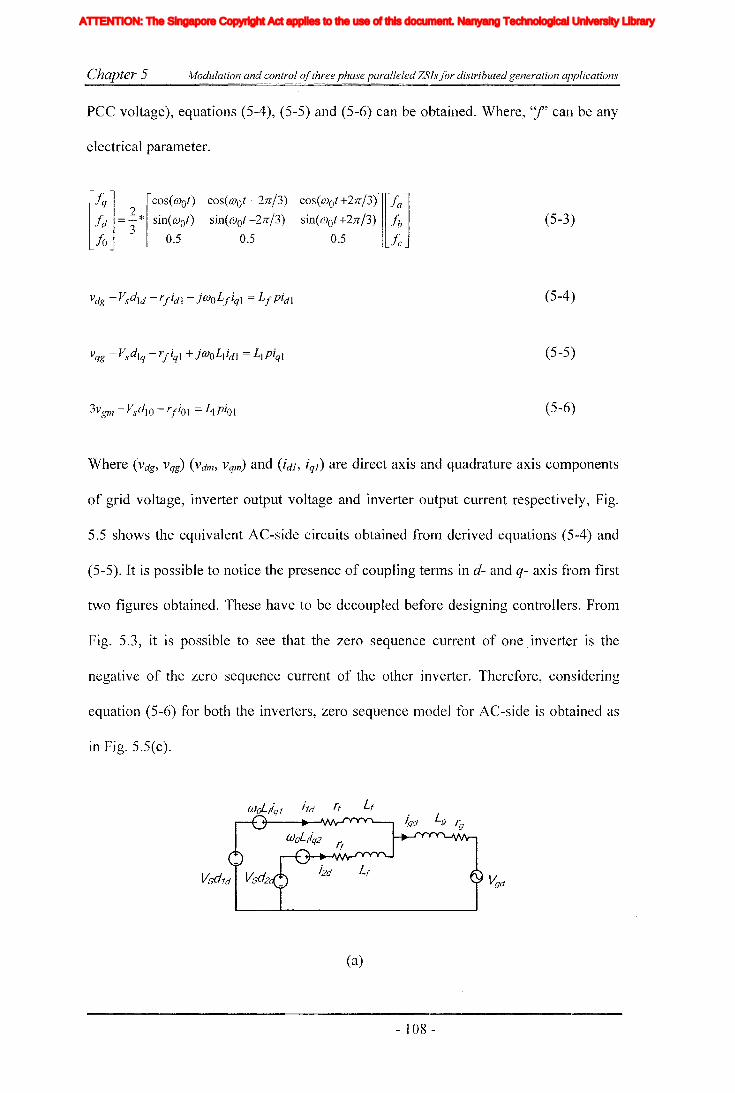
Chapter 5 Modulation and control ofthree phase paralleled ZSls for distributed generation applications
PCC voltage), equations (5-4), (5-5) and (5-6) can be obtained. Where, "I' can be any
electrical parameter.
[/q] [cos(mOt) cos(mot-27C13) cos(mot+27C13)][/a]!d = %* sinemot) sinemot - 27C13) sinemot +27C13) fb
10 0.5 0.5 0.5 Ie(5-3)
(5-4)
(5-5)
(5-6)
Where (Vdg, Vqg) (Vdm, vqm) and (idJ, iql) are direct axis and quadrature axis components
of grid voltage, inverter output voltage and inverter output current respectively, Fig.
5.5 shows the equivalent AC-side circuits obtained from derived equations (5-4) and
(5-5). It is possible to notice the presence of coupling terms in d- and q- axis from first
two figures obtained. These have to be decoupled before designing controllers. FrOln
Fig. 5.3, it is possible to see that the zero sequence current of one inverter is the
negative of the zero sequence current of the other inverter. Therefore, considering
equation (5-6) for both the inverters, zero sequence model for AC-side is obtained as
in Fig. 5.5(c).
(a)
- 108 -
Iiq
Iod
Ioq
I odq
I max
1,Ie, Ici,Ic2IDC
IL_m
I MPP
IpvI scITHD
IzI Zn
lap*lap
Ia,Ip,IoIa *, Ip*,10*
Iah,Iphlin
12n
I;
afJ axis currentafJ axis reference currentafJO axis current componentsafJO axis reference current componentsafJ axis harmonic current componentsNeutral current of inverter 1Neutral current of inverter 2Zero sequence reference current
Average Z-source inductor currentPerturbed Z-source inductor current
Perturbed load currentConstantGain factor of fifth harmonics filterGain factor of seventh harmonics filterGain factor of eleventh harmonics filterDC side controller proportional gain of PI controllerDC side controller integral gain of PI controllerGain of the inverterIntegral gain of PI controller in current controllerGain of the hth resonance filterProportional gain of AC side inner loop controllerProportional gain of PI controller in current controllerProportional gain of zero sequence resonance controllerIntegral gain of the resonance controllerIntegral gain of the zero sequence resonance controllerIntegral gain of the hth resonance controllerProportional gain of AC side PI controllerIntegral gain of the AC side PI controllerMultiplying factor for harmonics eliminationDC side filter inductanceLoad inductanceNeutral inductanceGrid inductanceLeakage inductance of transformer
XVII
ATTENTION: The Singapore Copyright Act applies to the use of this document. Nanyang Technological University Library
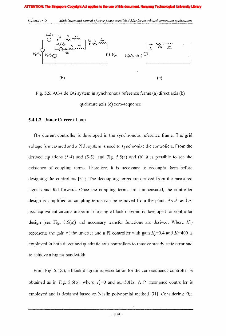
Chapter 5 Modulation and control ofthree phase paralleled ZSls for distributed generation applications
(b)
Vs(dlo
-d2o
)L I
(c)
Fig. 5.5. AC-side DG system in synchronous reference frame (a) direct axis (b)
qudrature axis (c) zero-sequence
5.4.1.2 Inner Current Loop
The current controller is developed in the synchronous reference frame. The grid
voltage is measured and a PLL system is used to synchronize the controllers. From the
derived equations (5-4) and (5-5), and Fig. 5.5(a) and (b) it is possible to see the
existence of coupling terms. Therefore, it is necessary to decouple them before
designing the controllers [31]. The decoupling terms are derived from the measured
signals and fed forward. Once the coupling terms are compensated, the controller
design is simplified as coupling terms can be removed from the plant. As d- and q-
axis equivalent circuits are similar, a single block diagram is developed for controller
design (see Fig. 5.6(a)) and necessary transfer functions are derived. Where K1C
represents the gain of the inverter and a PI controller with gain Kp=0.4 and K;=400 is
employed in both direct and quadratic axis controllers to remove steady state error and
to achieve a higher bandwidth.
From Fig. 5.5(c), a block diagram representation for the zero sequence controller is
obtained as in Fig. 5.6(1;'), where f; =0 and wo=50Hz. A P+resonance controller is
employed and is designed based on Naslin polynomial method [31]. Considering Fig.
- 109 -
Iiq
Iod
Ioq
I odq
I max
1,Ie, Ici,Ic2IDC
IL_m
I MPP
IpvI scITHD
IzI Zn
lap*lap
Ia,Ip,IoIa *, Ip*,10*
Iah,Iphlin
12n
I;
afJ axis currentafJ axis reference currentafJO axis current componentsafJO axis reference current componentsafJ axis harmonic current componentsNeutral current of inverter 1Neutral current of inverter 2Zero sequence reference current
Average Z-source inductor currentPerturbed Z-source inductor current
Perturbed load currentConstantGain factor of fifth harmonics filterGain factor of seventh harmonics filterGain factor of eleventh harmonics filterDC side controller proportional gain of PI controllerDC side controller integral gain of PI controllerGain of the inverterIntegral gain of PI controller in current controllerGain of the hth resonance filterProportional gain of AC side inner loop controllerProportional gain of PI controller in current controllerProportional gain of zero sequence resonance controllerIntegral gain of the resonance controllerIntegral gain of the zero sequence resonance controllerIntegral gain of the hth resonance controllerProportional gain of AC side PI controllerIntegral gain of the AC side PI controllerMultiplying factor for harmonics eliminationDC side filter inductanceLoad inductanceNeutral inductanceGrid inductanceLeakage inductance of transformer
XVII
ATTENTION: The Singapore Copyright Act applies to the use of this document. Nanyang Technological University Library
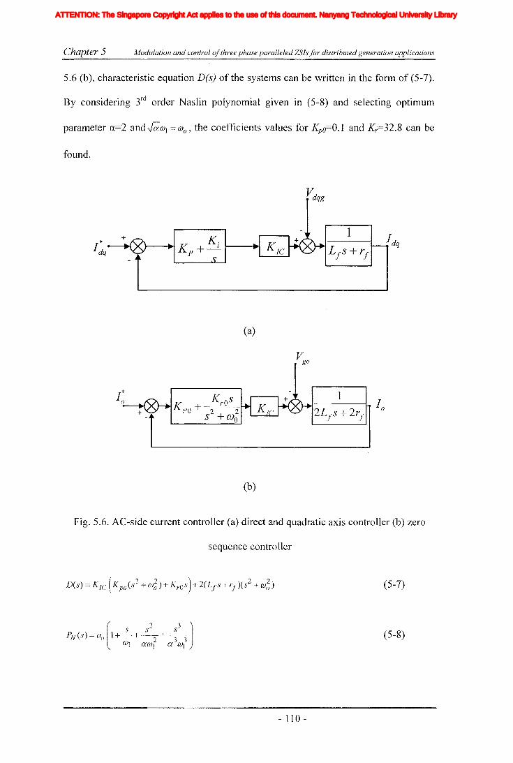
Chapter 5 Modulation and control ofthree phase paralleled ZSls for distributed generation applications
5.6 (b), characteristic equation D(s) of the systems can be written in the form of (5-7).
By considering 3rd order Naslin polynomial given in (5-8) and selecting optimUlTI
parameter «==2 and J;;cq = (J)o, the coefficients values for Kpo==O.l and Kr==32.8 can be
found.
(a)
1....J------I- 1
02Lf s + 2rf
(b)
Fig. 5.6. AC-side current controller (a) direct and quadratic axis controller (b) zero
sequence contralIer
(5-7)
(5-8)
- 110 -
Iiq
Iod
Ioq
I odq
I max
1,Ie, Ici,Ic2IDC
IL_m
I MPP
IpvI scITHD
IzI Zn
lap*lap
Ia,Ip,IoIa *, Ip*,10*
Iah,Iphlin
12n
I;
afJ axis currentafJ axis reference currentafJO axis current componentsafJO axis reference current componentsafJ axis harmonic current componentsNeutral current of inverter 1Neutral current of inverter 2Zero sequence reference current
Average Z-source inductor currentPerturbed Z-source inductor current
Perturbed load currentConstantGain factor of fifth harmonics filterGain factor of seventh harmonics filterGain factor of eleventh harmonics filterDC side controller proportional gain of PI controllerDC side controller integral gain of PI controllerGain of the inverterIntegral gain of PI controller in current controllerGain of the hth resonance filterProportional gain of AC side inner loop controllerProportional gain of PI controller in current controllerProportional gain of zero sequence resonance controllerIntegral gain of the resonance controllerIntegral gain of the zero sequence resonance controllerIntegral gain of the hth resonance controllerProportional gain of AC side PI controllerIntegral gain of the AC side PI controllerMultiplying factor for harmonics eliminationDC side filter inductanceLoad inductanceNeutral inductanceGrid inductanceLeakage inductance of transformer
XVII
ATTENTION: The Singapore Copyright Act applies to the use of this document. Nanyang Technological University Library
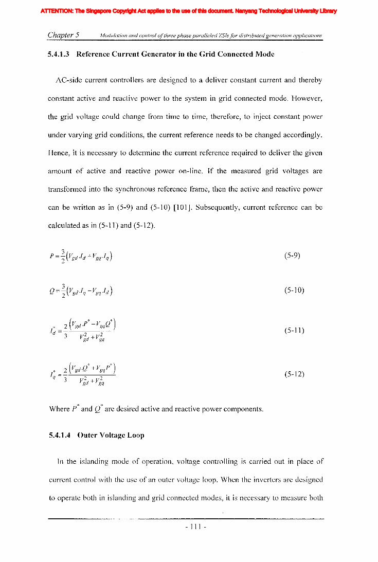
Chapter 5 Modulation and control ofthree phase paralleled ZSls for distributed generation applications
5.4.1.3 Reference Current Generator in the Grid Connected Mode
AC-side current controllers are designed to a deliver constant current and thereby
constant active and reactive power to the system in grid connected mode. However,
the grid voltage could change from time to time, therefore, to inject constant power
under varying grid conditions, the current reference needs to be changed accordingly.
Hence, it is necessary to determine the current reference required to deliver the given
amount of active and reactive power on-line. If the measured grid voltages are
transformed into the synchronous reference frame, then the active and reactive power
can be written as in (5-9) and (5-10) [101]. Subsequently, current reference can be
calculated as in (5.. 11) and (5-12).
(5-9)
(5-10)
(5-11)
(5-12)
Where p* and Q* are desired active and reactive power components.
5.4.1.4 Outer Voltage Loop
In the islanding mode of operation, voltage controlling is carried out in place of
current control with the use of an outer voltage loop. When the inverters are designed
to operate both in islanding and grid connected modes, it is necessary to lneasure both
- III -
Iiq
Iod
Ioq
I odq
I max
1,Ie, Ici,Ic2IDC
IL_m
I MPP
IpvI scITHD
IzI Zn
lap*lap
Ia,Ip,IoIa *, Ip*,10*
Iah,Iphlin
12n
I;
afJ axis currentafJ axis reference currentafJO axis current componentsafJO axis reference current componentsafJ axis harmonic current componentsNeutral current of inverter 1Neutral current of inverter 2Zero sequence reference current
Average Z-source inductor currentPerturbed Z-source inductor current
Perturbed load currentConstantGain factor of fifth harmonics filterGain factor of seventh harmonics filterGain factor of eleventh harmonics filterDC side controller proportional gain of PI controllerDC side controller integral gain of PI controllerGain of the inverterIntegral gain of PI controller in current controllerGain of the hth resonance filterProportional gain of AC side inner loop controllerProportional gain of PI controller in current controllerProportional gain of zero sequence resonance controllerIntegral gain of the resonance controllerIntegral gain of the zero sequence resonance controllerIntegral gain of the hth resonance controllerProportional gain of AC side PI controllerIntegral gain of the AC side PI controllerMultiplying factor for harmonics eliminationDC side filter inductanceLoad inductanceNeutral inductanceGrid inductanceLeakage inductance of transformer
XVII
ATTENTION: The Singapore Copyright Act applies to the use of this document. Nanyang Technological University Library
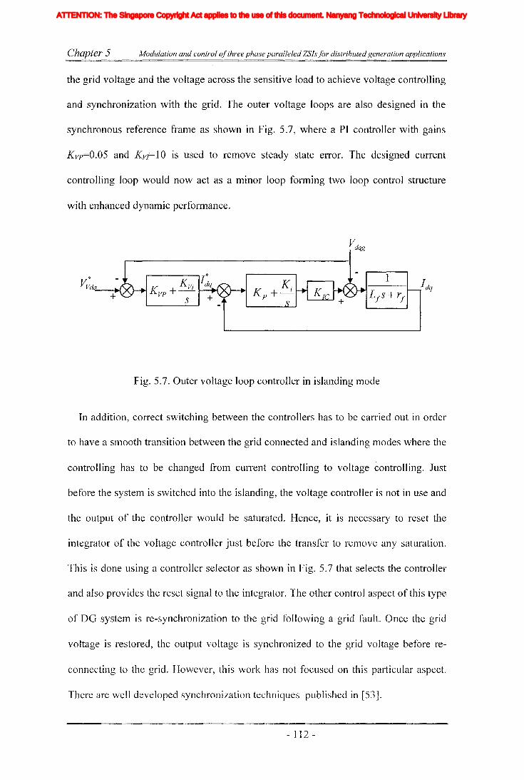
Chapter 5 Modulation and control ofthree phase paralleled ZSls for distributed generation applications
the grid voltage and the voltage across the sensitive load to achieve voltage controlling
and synchronization with the grid. The outer voltage loops are also designed in the
synchronous reference frame as shown in Fig. 5.7, where a PI controller with gains
Kvp=O.05 and KVl= lOis used to remove steady state error. The designed current
controlling loop would now act as a minor loop forming two loop control structure
with enhanced dynamic performance.
j*
K. KVi dq
vp+-s +
Fig. 5.7. Outer voltage loop controller in islanding mode
1
In addition, correct switching between the controllers has to be carried out in order
to have a smooth transition between the grid connected and islanding modes where the
controlling has to be changed from current controlling to voltage controlling. Just
before the system is switched into the islanding, the voltage controller is not in use and
the output of the controller would be saturated. Hence, it is necessary to reset the
integrator of the voltage controller just before the transfer to relllove any saturation.
This is done using a controller selector as shown in Fig. 5.7 that selects the controller
and also provides the reset signal to the integrator. The other control aspect of this type
of DG system is re-synchronization to the grid following a grid fault. Once the grid
voltage is restored, the output voltage is synchronized to the grid voltage before re-
connecting to the grid. However, this work has not focused on this particular aspect.
There are well developed synchronization techniques published in [53].
- 112 -
Iiq
Iod
Ioq
I odq
I max
1,Ie, Ici,Ic2IDC
IL_m
I MPP
IpvI scITHD
IzI Zn
lap*lap
Ia,Ip,IoIa *, Ip*,10*
Iah,Iphlin
12n
I;
afJ axis currentafJ axis reference currentafJO axis current componentsafJO axis reference current componentsafJ axis harmonic current componentsNeutral current of inverter 1Neutral current of inverter 2Zero sequence reference current
Average Z-source inductor currentPerturbed Z-source inductor current
Perturbed load currentConstantGain factor of fifth harmonics filterGain factor of seventh harmonics filterGain factor of eleventh harmonics filterDC side controller proportional gain of PI controllerDC side controller integral gain of PI controllerGain of the inverterIntegral gain of PI controller in current controllerGain of the hth resonance filterProportional gain of AC side inner loop controllerProportional gain of PI controller in current controllerProportional gain of zero sequence resonance controllerIntegral gain of the resonance controllerIntegral gain of the zero sequence resonance controllerIntegral gain of the hth resonance controllerProportional gain of AC side PI controllerIntegral gain of the AC side PI controllerMultiplying factor for harmonics eliminationDC side filter inductanceLoad inductanceNeutral inductanceGrid inductanceLeakage inductance of transformer
XVII
ATTENTION: The Singapore Copyright Act applies to the use of this document. Nanyang Technological University Library
Chapter 5 Modulation and control ofthree phase paralleled ZSls for distributed generation applications
VVdq p* --.... Referencecurrent
Q* --.... generator
Fig. 5.8. Operating mode selector
5.4.2 DC-side Controller
The main objective of the controller design is to integrate DO sources with varying
output DC voltages to the grid. The DC-side controller is designed to boost the voltage
and to provide a constant supply to the inverter while achieving fast recovery fronl
disturbances. Fig. 5.3 shows the simplified diagram of DC-side of the inverter system.
The equivalent DC-side current is calculated from the AC-side currents that are
transformed into synchronous reference frame as given in (5-13). However, with
proper control of zero sequence current, last two terms of the equation (5-13) vanishes
and the circuit becomes similar to the DC-side controller presented in the previous
chapter. Hence, the detailed mathematical modeling and controller design are not
presented here. The transfer function of the Z-source impedance network as given in
(5-14) is found to be a non-minimum phase system. Hence, an indirect controller with
an inner current loop and outer voltage loop is enlployed. The inner loop uses a
proportional controller with kp=O.5 and the outer loop uses PI constants kp=O.15 and
k i=20. As the output voltage of Z-source impedance network is pulsating, the
equivalent value of the voltage is derived using the measured voltage across one of Z-
source capacitors and shoot-through time as shown in Fig. 5.9. By adopting the
cushioning method proposed in the previous chapter, transfer of DC-side disturbance
- 113 -
Iiq
Iod
Ioq
I odq
I max
1,Ie, Ici,Ic2IDC
IL_m
I MPP
IpvI scITHD
IzI Zn
lap*lap
Ia,Ip,IoIa *, Ip*,10*
Iah,Iphlin
12n
I;
afJ axis currentafJ axis reference currentafJO axis current componentsafJO axis reference current componentsafJ axis harmonic current componentsNeutral current of inverter 1Neutral current of inverter 2Zero sequence reference current
Average Z-source inductor currentPerturbed Z-source inductor current
Perturbed load currentConstantGain factor of fifth harmonics filterGain factor of seventh harmonics filterGain factor of eleventh harmonics filterDC side controller proportional gain of PI controllerDC side controller integral gain of PI controllerGain of the inverterIntegral gain of PI controller in current controllerGain of the hth resonance filterProportional gain of AC side inner loop controllerProportional gain of PI controller in current controllerProportional gain of zero sequence resonance controllerIntegral gain of the resonance controllerIntegral gain of the zero sequence resonance controllerIntegral gain of the hth resonance controllerProportional gain of AC side PI controllerIntegral gain of the AC side PI controllerMultiplying factor for harmonics eliminationDC side filter inductanceLoad inductanceNeutral inductanceGrid inductanceLeakage inductance of transformer
XVII
ATTENTION: The Singapore Copyright Act applies to the use of this document. Nanyang Technological University Library
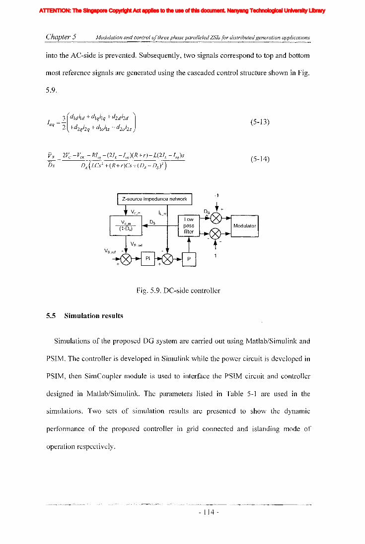
Chapter 5 Modulation and control ofthree phase paralleled ZSls for distributed generation applications
into the AC-side is prevented. Subsequently, two signals correspond to top and bottom
most reference signals are generated using the cascaded control structure shown in Fig.
5.9.
(5-13)
Vs
Ds
2VC -vDC -RIeq -(2IL -Ieq )(R+r)-L(2IL -Ieq)s
DA(LCs 2+(R+r)Cs+(DA-DS)2)(5-14)
+
-1Z-source impedance network
Vc_m IL_m ~os++
Vc m Os Low IL-..--_(1.....,-O,.-s_)~~--+---t ....._pa'"T'"s_s....J . MOdulator._ filter..
Fig. 5.9. DC-side controller
5.5 Simulation results
Simulations of the proposed DG system are carried out using Matlab/Simulink and
PSIM. The controller is developed in Simulink while the power circuit is developed in
PSIM, then SimCoupler module is used to interface the PSIM circuit and controller
designed in Matlab/Simulink. The parameters listed in Table 5-1 are used in the
simulations. Two sets of simulation results are presented to show the dynamic
performance of the proposed controller in grid connected and islanding mode of
operation respectively.
- 114 -
Iiq
Iod
Ioq
I odq
I max
1,Ie, Ici,Ic2IDC
IL_m
I MPP
IpvI scITHD
IzI Zn
lap*lap
Ia,Ip,IoIa *, Ip*,10*
Iah,Iphlin
12n
I;
afJ axis currentafJ axis reference currentafJO axis current componentsafJO axis reference current componentsafJ axis harmonic current componentsNeutral current of inverter 1Neutral current of inverter 2Zero sequence reference current
Average Z-source inductor currentPerturbed Z-source inductor current
Perturbed load currentConstantGain factor of fifth harmonics filterGain factor of seventh harmonics filterGain factor of eleventh harmonics filterDC side controller proportional gain of PI controllerDC side controller integral gain of PI controllerGain of the inverterIntegral gain of PI controller in current controllerGain of the hth resonance filterProportional gain of AC side inner loop controllerProportional gain of PI controller in current controllerProportional gain of zero sequence resonance controllerIntegral gain of the resonance controllerIntegral gain of the zero sequence resonance controllerIntegral gain of the hth resonance controllerProportional gain of AC side PI controllerIntegral gain of the AC side PI controllerMultiplying factor for harmonics eliminationDC side filter inductanceLoad inductanceNeutral inductanceGrid inductanceLeakage inductance of transformer
XVII
ATTENTION: The Singapore Copyright Act applies to the use of this document. Nanyang Technological University Library

Chapter 5 Modulation and control ofthree phase paralleled ZSls for distributed generation applications
5.5.1 Simulation results for grid connected operation
The first set of results show the rejection of a disturbance occurs at the source input
where the input supply voltage is changed from 90V to 70V at t==150ms (this is to
emulate voltage variation of a typical DG source). This demands a change in shoot-
through time and the output voltage of ZSI shows over-shoot and under-shoot as in
Fig. 5.1 0 (a) (top). With properly designed controllers, the AC-side shows minimal
effect resulting from the disturbance as shown in Fig. 5.1 0 (b). This shows the
rejection capability of the designed controller for disturbances arising from the input
side. However, to achieve desirable results, appropriate selection of the modulation
index and saturation limits suitable for a given operating range is necessary.
~ 100
>-0
140 160 180 200 220
100 I '-1'-
~I I
I I
U 50 1-- - -- -1- - - - - -- - - -1- -
> I 1 I
I I
0140 160 180 200 220
10
$ 5d
0140 160 180 200 220
Time (ms)
(a)
- I 15 -
Iiq
Iod
Ioq
I odq
I max
1,Ie, Ici,Ic2IDC
IL_m
I MPP
IpvI scITHD
IzI Zn
lap*lap
Ia,Ip,IoIa *, Ip*,10*
Iah,Iphlin
12n
I;
afJ axis currentafJ axis reference currentafJO axis current componentsafJO axis reference current componentsafJ axis harmonic current componentsNeutral current of inverter 1Neutral current of inverter 2Zero sequence reference current
Average Z-source inductor currentPerturbed Z-source inductor current
Perturbed load currentConstantGain factor of fifth harmonics filterGain factor of seventh harmonics filterGain factor of eleventh harmonics filterDC side controller proportional gain of PI controllerDC side controller integral gain of PI controllerGain of the inverterIntegral gain of PI controller in current controllerGain of the hth resonance filterProportional gain of AC side inner loop controllerProportional gain of PI controller in current controllerProportional gain of zero sequence resonance controllerIntegral gain of the resonance controllerIntegral gain of the zero sequence resonance controllerIntegral gain of the hth resonance controllerProportional gain of AC side PI controllerIntegral gain of the AC side PI controllerMultiplying factor for harmonics eliminationDC side filter inductanceLoad inductanceNeutral inductanceGrid inductanceLeakage inductance of transformer
XVII
ATTENTION: The Singapore Copyright Act applies to the use of this document. Nanyang Technological University Library

Chapter 5 Modulation and control ofthree phase paralleled ZSls for distributed generation applications
10
~ 001)-
140 150 160 170Time (illS)
180 190
(b)
Fig. 5.10. Response of the ZSI subjected to DC-side supply voltage step change of 90
to 70V (a) DC-side responses, from top to bottom, output voltage of Z-source
impedance network, voltage across the Z-source capacitor and inductor current, (b)
AC-side response, from top to bottom, grid current, current in inverter one, current in
inverter two and cross link current of one phase
190180160 170Time (ms)
150
$ 0
10,.---------,.------,------,---.,.-----.
$ 0~
(a)
- 116 -
Iiq
Iod
Ioq
I odq
I max
1,Ie, Ici,Ic2IDC
IL_m
I MPP
IpvI scITHD
IzI Zn
lap*lap
Ia,Ip,IoIa *, Ip*,10*
Iah,Iphlin
12n
I;
afJ axis currentafJ axis reference currentafJO axis current componentsafJO axis reference current componentsafJ axis harmonic current componentsNeutral current of inverter 1Neutral current of inverter 2Zero sequence reference current
Average Z-source inductor currentPerturbed Z-source inductor current
Perturbed load currentConstantGain factor of fifth harmonics filterGain factor of seventh harmonics filterGain factor of eleventh harmonics filterDC side controller proportional gain of PI controllerDC side controller integral gain of PI controllerGain of the inverterIntegral gain of PI controller in current controllerGain of the hth resonance filterProportional gain of AC side inner loop controllerProportional gain of PI controller in current controllerProportional gain of zero sequence resonance controllerIntegral gain of the resonance controllerIntegral gain of the zero sequence resonance controllerIntegral gain of the hth resonance controllerProportional gain of AC side PI controllerIntegral gain of the AC side PI controllerMultiplying factor for harmonics eliminationDC side filter inductanceLoad inductanceNeutral inductanceGrid inductanceLeakage inductance of transformer
XVII
ATTENTION: The Singapore Copyright Act applies to the use of this document. Nanyang Technological University Library

Chapter 5 Modulation and control ofthree phase paralleled ZSlsfor distributed generation applications
~ 100
'>o
140 160 180 200 220
~ 100Go 50>
- - 1- __
1
1
I
I
I
__________ 1 _I I
I IL J. I __
I
I
220160 180 200Time (ms)
140
o"--....I.-__...1.-__"--_---1-__---'-----J
140 160 180 200 22010..-------....---..------.----..----.
~d 5
o
(b)
Fig. 5.11. Response of the ZSI subjected to step change power reference (a) AC-side
response, from top to bottom, grid current, current in inverter one, current in inverter
two and cross link current of one phase (b) DC-side responses, from top to bottom,
output voltage of Z-source impedance network, voltage across the Z-source capacitor
and inductor current
Fig. 5.11 (a) shows silTIulated results for step change in grid current that results in
change in the reference value of the outer power loop. The output current shows good
reference tracking and it is also evident that the inverter exhibits good transient
characteristic and steady state load current sharing between them. However, this load
step change would disturb the DC-side as it would demand more energy to be
transferred to the AC-side causing an under-shoot in the output voltage of Z-source
network (see Fig. 5.11 (b) (top)). This would become significantly large for a big step
change in power references. This is avoided by adopting the cushioning method
developed in chapter 4. Furthermore, from Fig. 5.11 (a) (bottoln), it is possible to
observe that cross Iink current of a phase has only high frequency coupling current
thanks to the employment of zero sequence current controllers. Overall, results shows
- 117 -
Iiq
Iod
Ioq
I odq
I max
1,Ie, Ici,Ic2IDC
IL_m
I MPP
IpvI scITHD
IzI Zn
lap*lap
Ia,Ip,IoIa *, Ip*,10*
Iah,Iphlin
12n
I;
afJ axis currentafJ axis reference currentafJO axis current componentsafJO axis reference current componentsafJ axis harmonic current componentsNeutral current of inverter 1Neutral current of inverter 2Zero sequence reference current
Average Z-source inductor currentPerturbed Z-source inductor current
Perturbed load currentConstantGain factor of fifth harmonics filterGain factor of seventh harmonics filterGain factor of eleventh harmonics filterDC side controller proportional gain of PI controllerDC side controller integral gain of PI controllerGain of the inverterIntegral gain of PI controller in current controllerGain of the hth resonance filterProportional gain of AC side inner loop controllerProportional gain of PI controller in current controllerProportional gain of zero sequence resonance controllerIntegral gain of the resonance controllerIntegral gain of the zero sequence resonance controllerIntegral gain of the hth resonance controllerProportional gain of AC side PI controllerIntegral gain of the AC side PI controllerMultiplying factor for harmonics eliminationDC side filter inductanceLoad inductanceNeutral inductanceGrid inductanceLeakage inductance of transformer
XVII
ATTENTION: The Singapore Copyright Act applies to the use of this document. Nanyang Technological University Library
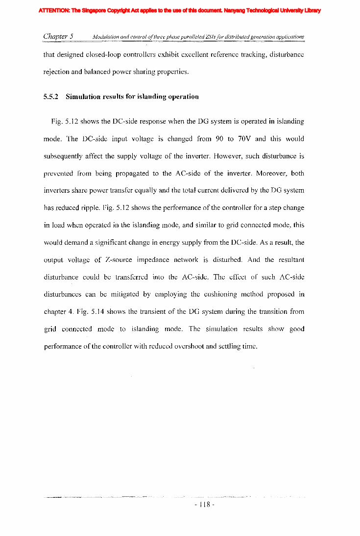
Chapter 5 Modulation and control ofthree phase paralleled ZSls for distributed generation applications
that designed closed-loop controllers exhibit excellent reference tracking, disturbance
rejection and balanced power sharing properties.
5..5..2 Simulation results for islanding operation
Fig. 5.12 shows the DC-side response when the DO system is operated in islanding
mode. The DC-side input voltage is changed from 90 to 70V and this would
subsequently affect the supply voltage of the inverter. However, such disturbance is
prevented from being propagated to the AC-side of the inverter. Moreover, both
inverters share power transfer equally and the total current delivered by the DO system
has reduced ripple. Fig. 5.12 shows the performance of the controller for a step change
in load when operated in the islanding mode, and similar to grid connected mode, this
would demand a significant change in energy supply from the DC-side. As a result, the
output voltage of Z-source impedance network is disturbed. And the resultant
disturbance could be transferred into the AC-side. The effect of such AC-side
disturbances can be mitigated by employing the cushioning method proposed in
chapter 4. Fig. 5.14 shows the transient of the DO system during the transition from
grid connected mode to islanding mode. The simulation results show good
performance of the controller with reduced overshoot and settling time.
- 118 -
Iiq
Iod
Ioq
I odq
I max
1,Ie, Ici,Ic2IDC
IL_m
I MPP
IpvI scITHD
IzI Zn
lap*lap
Ia,Ip,IoIa *, Ip*,10*
Iah,Iphlin
12n
I;
afJ axis currentafJ axis reference currentafJO axis current componentsafJO axis reference current componentsafJ axis harmonic current componentsNeutral current of inverter 1Neutral current of inverter 2Zero sequence reference current
Average Z-source inductor currentPerturbed Z-source inductor current
Perturbed load currentConstantGain factor of fifth harmonics filterGain factor of seventh harmonics filterGain factor of eleventh harmonics filterDC side controller proportional gain of PI controllerDC side controller integral gain of PI controllerGain of the inverterIntegral gain of PI controller in current controllerGain of the hth resonance filterProportional gain of AC side inner loop controllerProportional gain of PI controller in current controllerProportional gain of zero sequence resonance controllerIntegral gain of the resonance controllerIntegral gain of the zero sequence resonance controllerIntegral gain of the hth resonance controllerProportional gain of AC side PI controllerIntegral gain of the AC side PI controllerMultiplying factor for harmonics eliminationDC side filter inductanceLoad inductanceNeutral inductanceGrid inductanceLeakage inductance of transformer
XVII
ATTENTION: The Singapore Copyright Act applies to the use of this document. Nanyang Technological University Library
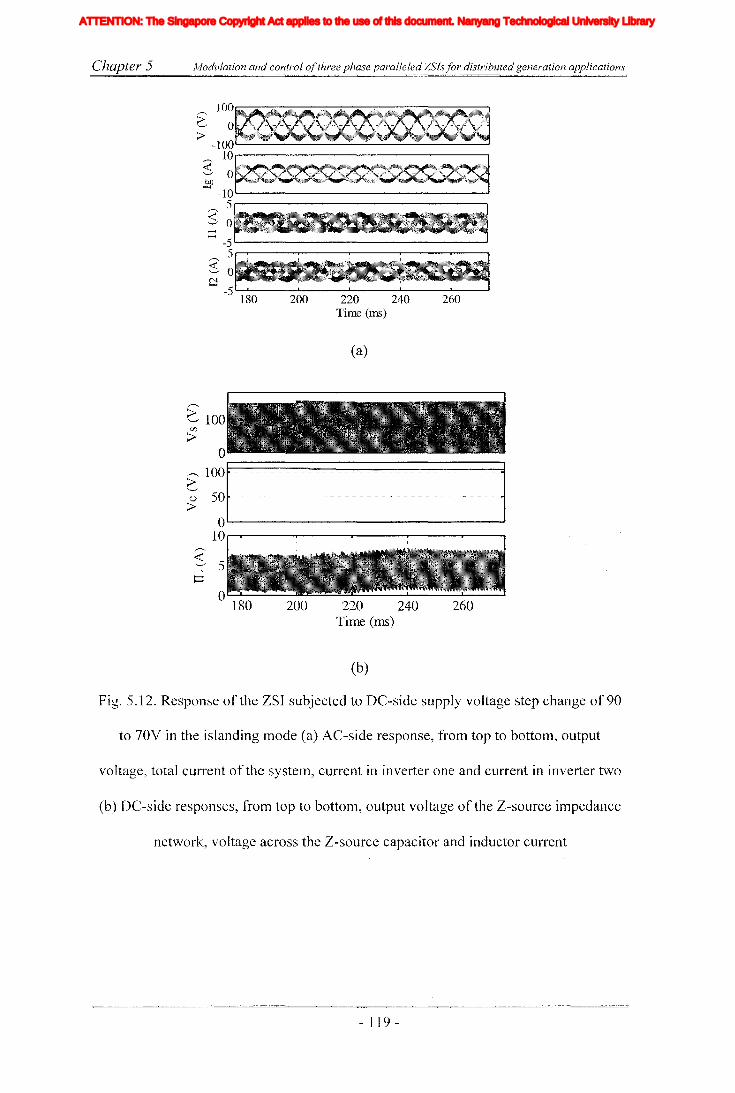
Chapter 5 lv/odulation and control ofthree phase paralleled ZSlsfor distributed generation applications
260220 240Time (ms)
200
100...--------------------.
~ 0>-100~-----------------'
~ 10...--------------------.
:$ 0~-10~---------------.J
5r------------------.
$ 0
~ -5~-----------------'5r--r---...---~--_r_--___r_-~
~ 0C!
-5 180
(a)
260220 240Time (ms)
--- Hu--------l
200o 180
~ 100i/J
>
(b)
Fig. 5.12. Response of the ZSI subjected to DC-side supply voltage step change of 90
to 70V in the islanding mode (a) AC-side response, from top to bottom, output
voltage, total current of the system, current in inverter one and current in inverter two
(b) DC-side responses, from top to bottom, output voltage of the Z-source impedance
network, voltage across the Z-source capacitor and inductor current
- ] 19 -
Iiq
Iod
Ioq
I odq
I max
1,Ie, Ici,Ic2IDC
IL_m
I MPP
IpvI scITHD
IzI Zn
lap*lap
Ia,Ip,IoIa *, Ip*,10*
Iah,Iphlin
12n
I;
afJ axis currentafJ axis reference currentafJO axis current componentsafJO axis reference current componentsafJ axis harmonic current componentsNeutral current of inverter 1Neutral current of inverter 2Zero sequence reference current
Average Z-source inductor currentPerturbed Z-source inductor current
Perturbed load currentConstantGain factor of fifth harmonics filterGain factor of seventh harmonics filterGain factor of eleventh harmonics filterDC side controller proportional gain of PI controllerDC side controller integral gain of PI controllerGain of the inverterIntegral gain of PI controller in current controllerGain of the hth resonance filterProportional gain of AC side inner loop controllerProportional gain of PI controller in current controllerProportional gain of zero sequence resonance controllerIntegral gain of the resonance controllerIntegral gain of the zero sequence resonance controllerIntegral gain of the hth resonance controllerProportional gain of AC side PI controllerIntegral gain of the AC side PI controllerMultiplying factor for harmonics eliminationDC side filter inductanceLoad inductanceNeutral inductanceGrid inductanceLeakage inductance of transformer
XVII
ATTENTION: The Singapore Copyright Act applies to the use of this document. Nanyang Technological University Library

Chapter 5 Modulation and control ofthree phase paralleled ZSls for distributed generation applications
100,..----------------......
~ 0>-
-lOO'-----------------.-J1O,..-----------~-~~~::--'~......
$ 0bJ)~
-10'-----------------.-J5r--------
$ 0~
~
-5 '-----------------~----------- ....5,....-.----,.---...,.---.....
$ 0CJ -5 '---a..--_.a.--_..r.....;;... ..a..-~...I,,;;;;;.. :...L.._~..,&,..;;:;. ._J
280 290 300 310 320 330 340 350Time (ms)
(a)
~ 100C.Il
>o
r--r---..,.----r----.-----,-----r----..,.----,
r--- 100G() 50>
1
I
I- - - -I
1
1
- '--I
I I
I I---,-- -I-
I I
1 I
- -~
I
I
I I-1----' ---
I I
1 IOl..--L.-_....L--_ _'___--L..._ __L._ __L._ ___'__ ____J
280 290 300 310 320 330 340 35015 ,..--....--..,.----.----.-----,-----.-----..,.----"l
~ 10
d 5O'---.a....;;...-..a..-~_'___ __a...__ __L._ __L._ ___'__ ____J
280 290 300 310 320 330 340 350Time (ms)
(b)
Fig. 5.13. Response of the ZSI subjected to load step change in the islanding mode (a)
AC-side response, frOln top to bottom, output voltage, total current of the system,
current in inverter one and current in inverter two (b) DC-side responses, from top to
bottom, output voltage of the Z-source impedance network, voltage across the Z-
source capacitor and inductor current
- 120 -
Iiq
Iod
Ioq
I odq
I max
1,Ie, Ici,Ic2IDC
IL_m
I MPP
IpvI scITHD
IzI Zn
lap*lap
Ia,Ip,IoIa *, Ip*,10*
Iah,Iphlin
12n
I;
afJ axis currentafJ axis reference currentafJO axis current componentsafJO axis reference current componentsafJ axis harmonic current componentsNeutral current of inverter 1Neutral current of inverter 2Zero sequence reference current
Average Z-source inductor currentPerturbed Z-source inductor current
Perturbed load currentConstantGain factor of fifth harmonics filterGain factor of seventh harmonics filterGain factor of eleventh harmonics filterDC side controller proportional gain of PI controllerDC side controller integral gain of PI controllerGain of the inverterIntegral gain of PI controller in current controllerGain of the hth resonance filterProportional gain of AC side inner loop controllerProportional gain of PI controller in current controllerProportional gain of zero sequence resonance controllerIntegral gain of the resonance controllerIntegral gain of the zero sequence resonance controllerIntegral gain of the hth resonance controllerProportional gain of AC side PI controllerIntegral gain of the AC side PI controllerMultiplying factor for harmonics eliminationDC side filter inductanceLoad inductanceNeutral inductanceGrid inductanceLeakage inductance of transformer
XVII
ATTENTION: The Singapore Copyright Act applies to the use of this document. Nanyang Technological University Library

Chapter 5 Modulation and control ofthree phase paralleled ZSls for distributed generation applications
320310300Time (ms)
290
100,...----------.,.---------,
~ 0>- -lOO'--------------------J~ lOr-----------------~
$ 0OJ)
~ -10'-------------------'5r-----------------~
~ 0.....~ -5'------------------8
5r--------.------r------r---~
~ 0N~
Fig. 5.14. Response of controller selector under transient from grid connected mode to
island, AC-side response from top to bottom output voltage, total current of the
system, current in inverter one and current in inverter two
5.6 Experimental verifications
A prototype of proposed paralleled ZSI based DG system is built in the laboratory.
Table 5-1 lists the component values and parameters used in designing the ZSI. A
three phase AC power supply connected to a resistive load bank is used to emulate the
grid. The controller is developed in dSPACE DS1103 based hardware environment
and necessary voltages and currents are measured using current and voltage sensors
and they are passed to the digital controller through AID converters. The designed
controller generates six sinusoidal reference voltages and two constant reference
values needed in generating the PWM signals and shoot-through signals respectively
to modulate the ZSIs. A modulator board is designed to produce PWM signals and
shoot-through signals by comparing interleaved triangular carrier and reference
signals. The generated shoot-through signals and PWM signals are then fed into an
Electronically Programmable Logic Device (EPLD) which inselis the shoot-through
intervals appropriately into the switching signals. The designed controller shows good
- 121 -
Iiq
Iod
Ioq
I odq
I max
1,Ie, Ici,Ic2IDC
IL_m
I MPP
IpvI scITHD
IzI Zn
lap*lap
Ia,Ip,IoIa *, Ip*,10*
Iah,Iphlin
12n
I;
afJ axis currentafJ axis reference currentafJO axis current componentsafJO axis reference current componentsafJ axis harmonic current componentsNeutral current of inverter 1Neutral current of inverter 2Zero sequence reference current
Average Z-source inductor currentPerturbed Z-source inductor current
Perturbed load currentConstantGain factor of fifth harmonics filterGain factor of seventh harmonics filterGain factor of eleventh harmonics filterDC side controller proportional gain of PI controllerDC side controller integral gain of PI controllerGain of the inverterIntegral gain of PI controller in current controllerGain of the hth resonance filterProportional gain of AC side inner loop controllerProportional gain of PI controller in current controllerProportional gain of zero sequence resonance controllerIntegral gain of the resonance controllerIntegral gain of the zero sequence resonance controllerIntegral gain of the hth resonance controllerProportional gain of AC side PI controllerIntegral gain of the AC side PI controllerMultiplying factor for harmonics eliminationDC side filter inductanceLoad inductanceNeutral inductanceGrid inductanceLeakage inductance of transformer
XVII
ATTENTION: The Singapore Copyright Act applies to the use of this document. Nanyang Technological University Library
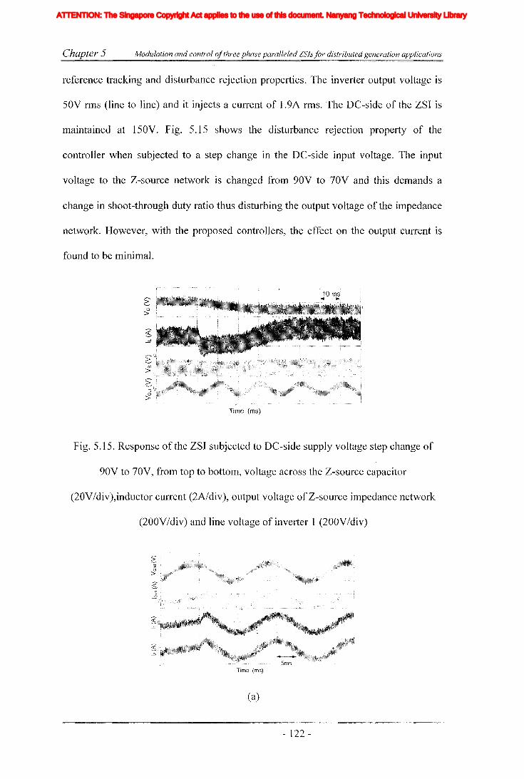
Chapter 5 Modulation and control a/three phase paralleled ZSls/or distributed generation applications
reference tracking and disturbance rejection properties. The inverter output voltage is
50V rms (line to line) and it injects a current of 1.9A rms. The DC-side of the ZSI is
maintained at 150V. Fig. 5.15 shows the disturbance rejection property of the
controller when subjected to a step change in the DC-side input voltage. The input
voltage to the Z-source network is changed from 90V to 70V and this demands a
change in shoot-through duty ratio thus disturbing the output voltage of the impedance
network. However, with the proposed controllers, the effect on the output current is
found to be minimal.
Time (ms)
Fig. 5.15. Response of the ZSl subjected to DC-side supply voltage step change of
90V to 70V, from top to bottom, voltage across the Z-source capacitor
(20V/div),inductor current (2A/div), output voltage of Z-source impedance network
(200V/div) and line voltage of inverter 1 (200V/div)
Time (ms)
(a)
- 122 -
Iiq
Iod
Ioq
I odq
I max
1,Ie, Ici,Ic2IDC
IL_m
I MPP
IpvI scITHD
IzI Zn
lap*lap
Ia,Ip,IoIa *, Ip*,10*
Iah,Iphlin
12n
I;
afJ axis currentafJ axis reference currentafJO axis current componentsafJO axis reference current componentsafJ axis harmonic current componentsNeutral current of inverter 1Neutral current of inverter 2Zero sequence reference current
Average Z-source inductor currentPerturbed Z-source inductor current
Perturbed load currentConstantGain factor of fifth harmonics filterGain factor of seventh harmonics filterGain factor of eleventh harmonics filterDC side controller proportional gain of PI controllerDC side controller integral gain of PI controllerGain of the inverterIntegral gain of PI controller in current controllerGain of the hth resonance filterProportional gain of AC side inner loop controllerProportional gain of PI controller in current controllerProportional gain of zero sequence resonance controllerIntegral gain of the resonance controllerIntegral gain of the zero sequence resonance controllerIntegral gain of the hth resonance controllerProportional gain of AC side PI controllerIntegral gain of the AC side PI controllerMultiplying factor for harmonics eliminationDC side filter inductanceLoad inductanceNeutral inductanceGrid inductanceLeakage inductance of transformer
XVII
ATTENTION: The Singapore Copyright Act applies to the use of this document. Nanyang Technological University Library

Chapter 5 Modulation and control ofthree phase paralleled ZSIs for distributed generation applications
(b)
Fig. 5.16. Response of the paralleled ZSI subjected to step change of current reference,
(a) AC-side response, from top to bottom, grid voltage (100 VIdiv), grid current
(SA/div), current of inverter one (2A/div), current of inverter two (2A/div) (b) DC-side
responses, from top to bottom, voltage across the Z-source capacitor (20V/div),
inductor current (IA/div) and current in one phase (SA/div)
Fig. 5.16 shows a step change in the AC current injected to the grid resulting from a
change in the power reference. This power reference could result from change in
~
output power in energy source or change in load demand. However, these current
reference changes should not lead the energy source to operate in undesirable
operating regions. The line current reference is changed from O.4A to 1.9A rms. Fig.
S.16(a) shows corresponding change in the output current waveforn1s and the currents
tracking their references without significant delay. Fig. 5.16(b) shows voltage across
the Z-source capacitor and Z-source inductor current. Both variables settle fast in
stable manner. However, for significantly large power step changes there could be a
possibility of larger disturbance appearing in the DC-side. Hence, it is necessary to
have a sufficiently large null interval to absorb such DC-side disturbances as presented
in [102J and chapter 4.
- 123 -
Iiq
Iod
Ioq
I odq
I max
1,Ie, Ici,Ic2IDC
IL_m
I MPP
IpvI scITHD
IzI Zn
lap*lap
Ia,Ip,IoIa *, Ip*,10*
Iah,Iphlin
12n
I;
afJ axis currentafJ axis reference currentafJO axis current componentsafJO axis reference current componentsafJ axis harmonic current componentsNeutral current of inverter 1Neutral current of inverter 2Zero sequence reference current
Average Z-source inductor currentPerturbed Z-source inductor current
Perturbed load currentConstantGain factor of fifth harmonics filterGain factor of seventh harmonics filterGain factor of eleventh harmonics filterDC side controller proportional gain of PI controllerDC side controller integral gain of PI controllerGain of the inverterIntegral gain of PI controller in current controllerGain of the hth resonance filterProportional gain of AC side inner loop controllerProportional gain of PI controller in current controllerProportional gain of zero sequence resonance controllerIntegral gain of the resonance controllerIntegral gain of the zero sequence resonance controllerIntegral gain of the hth resonance controllerProportional gain of AC side PI controllerIntegral gain of the AC side PI controllerMultiplying factor for harmonics eliminationDC side filter inductanceLoad inductanceNeutral inductanceGrid inductanceLeakage inductance of transformer
XVII
ATTENTION: The Singapore Copyright Act applies to the use of this document. Nanyang Technological University Library

Chapter 5 Modulation and control ofthree phase paralleled ZSIs for distributed generation applications
(a)
Time (ms)
(b)
Fig. 5.17. Response of the paralleled ZSI subjected to step change of load current in
the islanding mode, (a) AC-side response, from top to bottom, grid voltage (100
V/div), current in inverter one (2A/div), current in inverter two (2A/div), grid current
(5A/div), (b) DC-side responses, from top to bottom, voltage across the Z-source
capacitor (20V/div), output voltage of impedance network, inductor current (lA/div)
and current in one phase (5A/div)
Figs. 5.17 and 5.18 show the controller perfonnance in islanding conditions. Fig.
5.17 shows the response of the system when subjected to a step change in load and this
is emulated with switching of some resistor banks. Results show good performance
with fast voltage and current response and the inverters tend to share currents equally.
Whereas Fig. 5. 18 shows the response of the controller \tvhen subjected to a step
- 124 -
Iiq
Iod
Ioq
I odq
I max
1,Ie, Ici,Ic2IDC
IL_m
I MPP
IpvI scITHD
IzI Zn
lap*lap
Ia,Ip,IoIa *, Ip*,10*
Iah,Iphlin
12n
I;
afJ axis currentafJ axis reference currentafJO axis current componentsafJO axis reference current componentsafJ axis harmonic current componentsNeutral current of inverter 1Neutral current of inverter 2Zero sequence reference current
Average Z-source inductor currentPerturbed Z-source inductor current
Perturbed load currentConstantGain factor of fifth harmonics filterGain factor of seventh harmonics filterGain factor of eleventh harmonics filterDC side controller proportional gain of PI controllerDC side controller integral gain of PI controllerGain of the inverterIntegral gain of PI controller in current controllerGain of the hth resonance filterProportional gain of AC side inner loop controllerProportional gain of PI controller in current controllerProportional gain of zero sequence resonance controllerIntegral gain of the resonance controllerIntegral gain of the zero sequence resonance controllerIntegral gain of the hth resonance controllerProportional gain of AC side PI controllerIntegral gain of the AC side PI controllerMultiplying factor for harmonics eliminationDC side filter inductanceLoad inductanceNeutral inductanceGrid inductanceLeakage inductance of transformer
XVII
ATTENTION: The Singapore Copyright Act applies to the use of this document. Nanyang Technological University Library
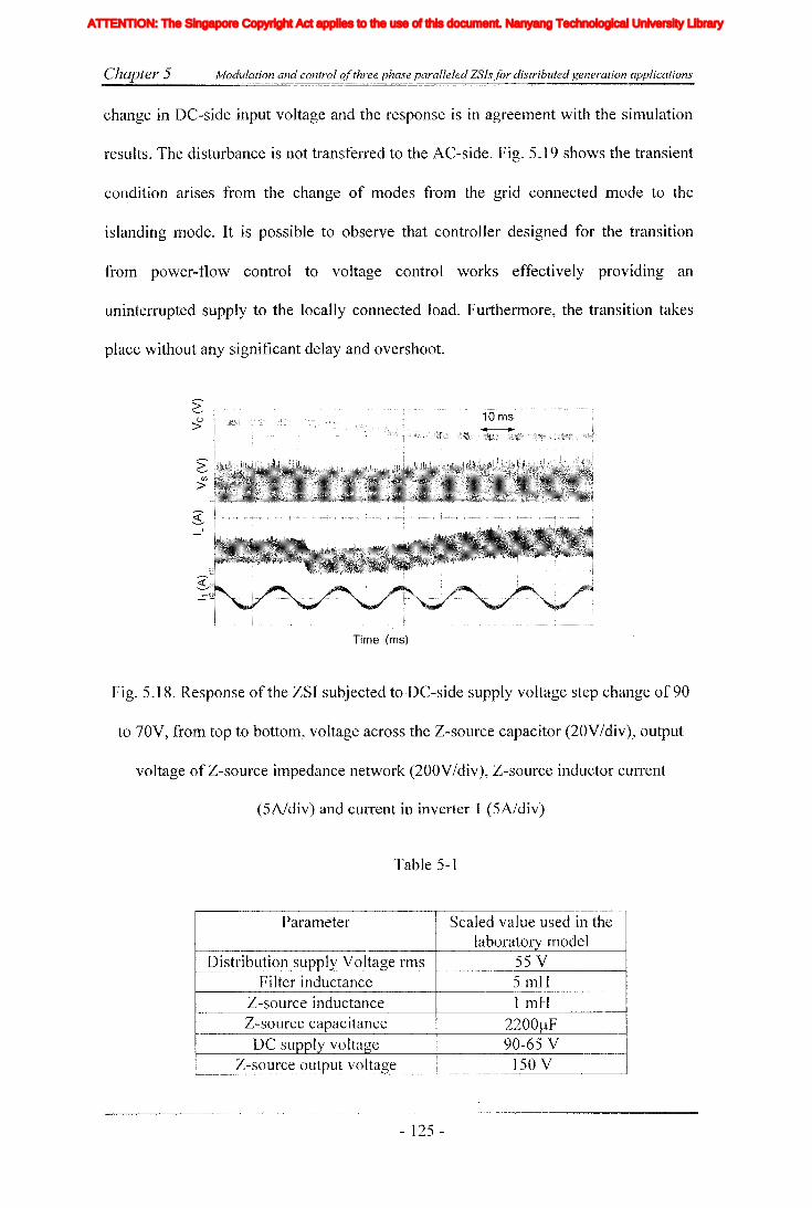
Chapter 5 Modulation and control ofthree phase paralleled ZSIs for distributed generation applications
change in DC-side input voltage and the response is in agreement with the simulation
results. The disturbance is not transferred to the AC-side. Fig. 5.19 shows the transient
condition arises from the change of modes from the grid connected mode to the
islanding mode. It is possible to observe that controller designed for the transition
from power-flow control to voltage control works effectively providing an
uninterrupted supply to the locally connected load. Furthermore, the transition takes
place without any significant delay and overshoot.
Time (ms)
Fig. 5.18. Response of the ZSI subjected to DC-side supply voltage step change of 90
to 70V, from top to bottom, voltage across the Z-source capacitor (20VIdiv), output
voltage of Z-source impedance network (200VIdiv), Z-source inductor current
(5A/div) and current in inverter 1 (5A/div)
Table 5-1
Parameter Scaled value used in thelaboratory model
Distribution supply Voltage rms 55 VFilter inductance 5mH
Z-source inductance 1 mtIZ-source capacitance 2200J.!F
DC supply voltage 90-65 VZ-source output voltage 150 V
- 125 -
Iiq
Iod
Ioq
I odq
I max
1,Ie, Ici,Ic2IDC
IL_m
I MPP
IpvI scITHD
IzI Zn
lap*lap
Ia,Ip,IoIa *, Ip*,10*
Iah,Iphlin
12n
I;
afJ axis currentafJ axis reference currentafJO axis current componentsafJO axis reference current componentsafJ axis harmonic current componentsNeutral current of inverter 1Neutral current of inverter 2Zero sequence reference current
Average Z-source inductor currentPerturbed Z-source inductor current
Perturbed load currentConstantGain factor of fifth harmonics filterGain factor of seventh harmonics filterGain factor of eleventh harmonics filterDC side controller proportional gain of PI controllerDC side controller integral gain of PI controllerGain of the inverterIntegral gain of PI controller in current controllerGain of the hth resonance filterProportional gain of AC side inner loop controllerProportional gain of PI controller in current controllerProportional gain of zero sequence resonance controllerIntegral gain of the resonance controllerIntegral gain of the zero sequence resonance controllerIntegral gain of the hth resonance controllerProportional gain of AC side PI controllerIntegral gain of the AC side PI controllerMultiplying factor for harmonics eliminationDC side filter inductanceLoad inductanceNeutral inductanceGrid inductanceLeakage inductance of transformer
XVII
ATTENTION: The Singapore Copyright Act applies to the use of this document. Nanyang Technological University Library

Chapter 5 - Modulation and control ofthree phase paralleled ZSls for distributed generation applications
Time (ms)
(a)
(b)
Fig. 5.19. Response of controller selector for transition froln grid connected mode to
islanding mode, (a) AC-side response, from top to bottom, output voltage(l OOV/div),
total current of the system(5A/div), current in inverter one(2A/div) and current in
inverter two(2A/div), (b) DC-side response, from top to bottom, voltage across the Z-
source capacitor (20V/div), Z-source inductor current (5A/div), voltage at load bus
(100 V/div) and total current (5A/div)
- 126 -
Iiq
Iod
Ioq
I odq
I max
1,Ie, Ici,Ic2IDC
IL_m
I MPP
IpvI scITHD
IzI Zn
lap*lap
Ia,Ip,IoIa *, Ip*,10*
Iah,Iphlin
12n
I;
afJ axis currentafJ axis reference currentafJO axis current componentsafJO axis reference current componentsafJ axis harmonic current componentsNeutral current of inverter 1Neutral current of inverter 2Zero sequence reference current
Average Z-source inductor currentPerturbed Z-source inductor current
Perturbed load currentConstantGain factor of fifth harmonics filterGain factor of seventh harmonics filterGain factor of eleventh harmonics filterDC side controller proportional gain of PI controllerDC side controller integral gain of PI controllerGain of the inverterIntegral gain of PI controller in current controllerGain of the hth resonance filterProportional gain of AC side inner loop controllerProportional gain of PI controller in current controllerProportional gain of zero sequence resonance controllerIntegral gain of the resonance controllerIntegral gain of the zero sequence resonance controllerIntegral gain of the hth resonance controllerProportional gain of AC side PI controllerIntegral gain of the AC side PI controllerMultiplying factor for harmonics eliminationDC side filter inductanceLoad inductanceNeutral inductanceGrid inductanceLeakage inductance of transformer
XVII
ATTENTION: The Singapore Copyright Act applies to the use of this document. Nanyang Technological University Library

Chapter 5 Modulation and control ofthree phase paralleled ZSls for distributed generation applications
5.7 Discussion
In this chapter, modulation and controlling of paralleled ZSI system for DG
application is proposed. The proposed DO system is designed to operate in both grid
connected and islanding modes. Towards this end, a carrier based modulation method
is proposed and is designed based on simple shoot-through with interleaved carrier
signals. Then, based on the transfer function mathematical model of ZSI, controllers
are designed for both DC and AC sides of the inverter. The DC-side controller is
designed to supply a constant input voltage to the inverters while rejecting
disturbances from the supply side by varying the shoot-through time appropriately.
The AC-side controllers are designed to deliver constant active and reactive power in
the grid connected mode. In achieving that, a balanced set of currents is injected into
the grid. The current references are generated using an outer power loop. Where
desired active, reactive power values and measured grid voltages are used to calculate
the current references. In the islanding mode, AC-side controllers are designed to
supply a constant voltage to a locally connected load. The load voltage is measured
and controlled in closed loop manner. A controller selector is designed to select the
operating mode and also it provides reset signals to the integrators of the voltage
controllers. This would remove the saturation in controller integrators and hence
prevent large distortions in output voltage during the transition. As a result continuous
supply is maintained at the local sensitive load. Also, with open- and closed loop
simulations, it is observed that DC-side disturbances could be transferred into the AC
side. These characteristics could impose cOlnplications in designing the controllers.
However, these are overcome by proper selection of control variables and parameters
and also with the adoption of cushioning method by changing the modulation index
appropriately. Simulation and experimental results show excellent reference tracking
- 127 -
Iiq
Iod
Ioq
I odq
I max
1,Ie, Ici,Ic2IDC
IL_m
I MPP
IpvI scITHD
IzI Zn
lap*lap
Ia,Ip,IoIa *, Ip*,10*
Iah,Iphlin
12n
I;
afJ axis currentafJ axis reference currentafJO axis current componentsafJO axis reference current componentsafJ axis harmonic current componentsNeutral current of inverter 1Neutral current of inverter 2Zero sequence reference current
Average Z-source inductor currentPerturbed Z-source inductor current
Perturbed load currentConstantGain factor of fifth harmonics filterGain factor of seventh harmonics filterGain factor of eleventh harmonics filterDC side controller proportional gain of PI controllerDC side controller integral gain of PI controllerGain of the inverterIntegral gain of PI controller in current controllerGain of the hth resonance filterProportional gain of AC side inner loop controllerProportional gain of PI controller in current controllerProportional gain of zero sequence resonance controllerIntegral gain of the resonance controllerIntegral gain of the zero sequence resonance controllerIntegral gain of the hth resonance controllerProportional gain of AC side PI controllerIntegral gain of the AC side PI controllerMultiplying factor for harmonics eliminationDC side filter inductanceLoad inductanceNeutral inductanceGrid inductanceLeakage inductance of transformer
XVII
ATTENTION: The Singapore Copyright Act applies to the use of this document. Nanyang Technological University Library

Chapter 5 Modulation and control ofthree phase paralleled ZSls for distributed generation applications
and rejection of disturbances arising from input and output sides both in grid
connected and islanding n1odes. Furthermore, controllers would facilitate SITIooth
transition between controllers.
- 128 -
Iiq
Iod
Ioq
I odq
I max
1,Ie, Ici,Ic2IDC
IL_m
I MPP
IpvI scITHD
IzI Zn
lap*lap
Ia,Ip,IoIa *, Ip*,10*
Iah,Iphlin
12n
I;
afJ axis currentafJ axis reference currentafJO axis current componentsafJO axis reference current componentsafJ axis harmonic current componentsNeutral current of inverter 1Neutral current of inverter 2Zero sequence reference current
Average Z-source inductor currentPerturbed Z-source inductor current
Perturbed load currentConstantGain factor of fifth harmonics filterGain factor of seventh harmonics filterGain factor of eleventh harmonics filterDC side controller proportional gain of PI controllerDC side controller integral gain of PI controllerGain of the inverterIntegral gain of PI controller in current controllerGain of the hth resonance filterProportional gain of AC side inner loop controllerProportional gain of PI controller in current controllerProportional gain of zero sequence resonance controllerIntegral gain of the resonance controllerIntegral gain of the zero sequence resonance controllerIntegral gain of the hth resonance controllerProportional gain of AC side PI controllerIntegral gain of the AC side PI controllerMultiplying factor for harmonics eliminationDC side filter inductanceLoad inductanceNeutral inductanceGrid inductanceLeakage inductance of transformer
XVII
ATTENTION: The Singapore Copyright Act applies to the use of this document. Nanyang Technological University Library
Chapter 6 ZSI basedjlexible DC systems to enhance the power quality
Chapter 6
ZSI based flexible DG systems to enhance the power
quality
6.1 Introduction
Present day power consumes need to grapple with numerous power quality
problems, among them harmonics and unbalances are of grate concern. As nonlinear
loads connected at distribution level have increased immensely concerted action of
such loads drawing nonlinear currents would cause deterioration of voltage quality at
the distribution level [19, 30,47, 103]. This may lead to malfunctioning of sensitive
loads. The regulatory bodies have specified harmonic standards on the acceptable
harmonic levels that are allowed to inject into the grid by the consumer load as well as
the levels that have to be maintained by the utility. Generally, active filters are used to
compensate harmonics by utilities and the large consumers [19, 30, 47]. Furthermore,
in many countries the distribution networks are four wire systems that are heavily
loaded with single phase residential and industrial loads and grids are susceptible to
asymmetrical faults. These phenomena's could lead to increase in unbalances and as
such, increase in the negative and zero sequence components. Particularly, negative
sequence components could affect the loads and generating sources as well. In order to
minimize its effects, numerous standards are setup by power system operation
governing bodies to safeguard the consumers. According to lEe standards, the
allowable level of unbalance factor should be less than 2%. Predominantly, in
distribution systems with weak grid conditions or microgrid operated in islanding
- 129 -
Iiq
Iod
Ioq
I odq
I max
1,Ie, Ici,Ic2IDC
IL_m
I MPP
IpvI scITHD
IzI Zn
lap*lap
Ia,Ip,IoIa *, Ip*,10*
Iah,Iphlin
12n
I;
afJ axis currentafJ axis reference currentafJO axis current componentsafJO axis reference current componentsafJ axis harmonic current componentsNeutral current of inverter 1Neutral current of inverter 2Zero sequence reference current
Average Z-source inductor currentPerturbed Z-source inductor current
Perturbed load currentConstantGain factor of fifth harmonics filterGain factor of seventh harmonics filterGain factor of eleventh harmonics filterDC side controller proportional gain of PI controllerDC side controller integral gain of PI controllerGain of the inverterIntegral gain of PI controller in current controllerGain of the hth resonance filterProportional gain of AC side inner loop controllerProportional gain of PI controller in current controllerProportional gain of zero sequence resonance controllerIntegral gain of the resonance controllerIntegral gain of the zero sequence resonance controllerIntegral gain of the hth resonance controllerProportional gain of AC side PI controllerIntegral gain of the AC side PI controllerMultiplying factor for harmonics eliminationDC side filter inductanceLoad inductanceNeutral inductanceGrid inductanceLeakage inductance of transformer
XVII
ATTENTION: The Singapore Copyright Act applies to the use of this document. Nanyang Technological University Library
Chapter 6 ZSI basedflexible DG systems to enhance the power quality
lTIode, the effects of unbalances can be significant. Such systems could go into
unbalance even with smaller amount of negative sequence currents. In case of highly
unbalanced conditions, some of the generation units connected at distribution level
may be forced to shutdown by their protection system further worsening the situation
[41]. Therefore, it is necessary to control the negative sequence components in the
system. Usually, SVC and APF with special control algorithms are used to mitigate
the negative sequence components in larger consumer loads [25,41].
With the increase in energy demand, sources like fuel cells and solar cells are
increasingly connected at the distribution level. Generally, these sources are connected
to the grid through inverters and their main function is to deliver active power into the
grid. Usually, they are operated at unity power factor but some of the systems are
designed to inject or absorb reactive power. However, some of the DG systems may
not supply power to the grid all the time due to many factors like the unavailability of
source and demand price consideration etc. In such scenarios, the inverter used in
power conversion can be left with some unused capacity. This could be used to
provide some ancillary functions like harmonic and unbalance mitigation of the power
distribution system. Moreover, some of these DG sources have large operating range
demanding special converters with wide operating range. Therefore, being a single
stage buck-boost inverter, recently proposed ZSI is a good candidate for future DG
systems.
I-Iowever, DG systems are still not widely used for other ancillary functions of the
power distribution. With sophisticated and flexible DO systems, it would indeed be
possible to implelnent integrated functions like harmonic and unbalance mitigation
and zero sequence component suppression etc. The new trends in power electronic
- 130 -
Iiq
Iod
Ioq
I odq
I max
1,Ie, Ici,Ic2IDC
IL_m
I MPP
IpvI scITHD
IzI Zn
lap*lap
Ia,Ip,IoIa *, Ip*,10*
Iah,Iphlin
12n
I;
afJ axis currentafJ axis reference currentafJO axis current componentsafJO axis reference current componentsafJ axis harmonic current componentsNeutral current of inverter 1Neutral current of inverter 2Zero sequence reference current
Average Z-source inductor currentPerturbed Z-source inductor current
Perturbed load currentConstantGain factor of fifth harmonics filterGain factor of seventh harmonics filterGain factor of eleventh harmonics filterDC side controller proportional gain of PI controllerDC side controller integral gain of PI controllerGain of the inverterIntegral gain of PI controller in current controllerGain of the hth resonance filterProportional gain of AC side inner loop controllerProportional gain of PI controller in current controllerProportional gain of zero sequence resonance controllerIntegral gain of the resonance controllerIntegral gain of the zero sequence resonance controllerIntegral gain of the hth resonance controllerProportional gain of AC side PI controllerIntegral gain of the AC side PI controllerMultiplying factor for harmonics eliminationDC side filter inductanceLoad inductanceNeutral inductanceGrid inductanceLeakage inductance of transformer
XVII
ATTENTION: The Singapore Copyright Act applies to the use of this document. Nanyang Technological University Library

Chapter 6 ZSI basedflexible DC systems to enhance the power quality
converters make the implementation of such multiple functions feasible [19, 20, 30,
41,42, 104]. The main theme of this chapter is to exploit the unused capacity of Z
source based DG power converter systems, if any, and reduce the cost of installing
dedicated units for carrying out ancillary services. Particularly, at the distribution
level, it may not be economical to have dedicated systems to handle such ancillary
servIces.
Considering these factors, this chapter presents controller design for a ZSI based
DG system to improve power quality of distribution systems. To improve the reference
tracking and the elimination of harmonics, a P+resonance cum repetitive controller
with a simple time delay is proposed. When the system is operated at full capacity, the
proposed controller improves the quality of the injecting current. The duality of this
internalITIodel based control structure is exploited to improve the voltage quality at the
connection point of the inverter when the system is not operated in full power
capacity.
Secondly, this chapter proposes a DG system based on four-leg parallel ZSIs in
integrating a renewable generation system into the grid. Particularly, four-leg DG
scheme could give flexibility to the DG system by supporting other functions of power
distribution like control of zero sequence components and unbalance mitigation. To
increase the capacity and to have redundancy, a parallel structure for the ZSI is
proposed. The emphasis is given to component count and the modular structure,
thereby reducing the cost while achieving the system reliability. A modulation method
is proposed based on interleaved carriers to reduce the output current ripple. Separate
controllers are designed in stationary reference frame for the AC-side of each inverter.
The AC-side controller is designed using a combination of P+resonance and negative
- 131 -
Iiq
Iod
Ioq
I odq
I max
1,Ie, Ici,Ic2IDC
IL_m
I MPP
IpvI scITHD
IzI Zn
lap*lap
Ia,Ip,IoIa *, Ip*,10*
Iah,Iphlin
12n
I;
afJ axis currentafJ axis reference currentafJO axis current componentsafJO axis reference current componentsafJ axis harmonic current componentsNeutral current of inverter 1Neutral current of inverter 2Zero sequence reference current
Average Z-source inductor currentPerturbed Z-source inductor current
Perturbed load currentConstantGain factor of fifth harmonics filterGain factor of seventh harmonics filterGain factor of eleventh harmonics filterDC side controller proportional gain of PI controllerDC side controller integral gain of PI controllerGain of the inverterIntegral gain of PI controller in current controllerGain of the hth resonance filterProportional gain of AC side inner loop controllerProportional gain of PI controller in current controllerProportional gain of zero sequence resonance controllerIntegral gain of the resonance controllerIntegral gain of the zero sequence resonance controllerIntegral gain of the hth resonance controllerProportional gain of AC side PI controllerIntegral gain of the AC side PI controllerMultiplying factor for harmonics eliminationDC side filter inductanceLoad inductanceNeutral inductanceGrid inductanceLeakage inductance of transformer
XVII
ATTENTION: The Singapore Copyright Act applies to the use of this document. Nanyang Technological University Library

Chapter 6 ZSl basedflexible DC systems to enhance the power quality
feedback time delay. This combined controller would deliver good reference tracking
and harmonic rejection properties. Another controller is designed for the DC-side Z
source impedance network to mitigate the fluctuations in the renewable source. The
whole system is driven from a higher level controller that would generate current
references to operate the total system in two operating modes, to deliver specified
power and to control the unbalances and zero sequence. Proposed topologies and
control methods are tested with simulation results obtained using Matlab/Simulink and
PLECS. Subsequently, they are experimentally validated using laboratory prototypes.
6.2 P+resonance and repetitive controllers for harmonics elimination
Power quality of the grid connected inverters is one of the major aspects need to be
considered when designing controllers. IEEE 1547 specifies the grid connecting
standards and IEEE 519 and IEEE 929 specifies the harmonic limits of the grid
connected inverters. To meet these standards, a current controller needs to be designed
with the ability of mitigating harmonics. Although synchronous frame PI controllers
are widely used in grid connected inverters, they would only eliminate disturbances
occurred either in positive or negative synchronous reference frame [53]. This problem
could be overCOlne by having controllers designed in both positive and negative
sequence reference frames. Nevertheless, their effectiveness in eliminating harmonics
does not satisfy IEEE standards. Therefore, specific hannonic compensators need to be
utilized. A new control structure, P+resonance controller (6-1) was proposed in [105].
This controller is designed based on the internal model principle and it is operated in
the stationary frame. The main advantages of the P+resonance controller is that it does
not need two reference frames to operate while rejecting both positive and negative
sequence disturbances equally giving the performance of a conventional PI controller
- ] 32 -
Iiq
Iod
Ioq
I odq
I max
1,Ie, Ici,Ic2IDC
IL_m
I MPP
IpvI scITHD
IzI Zn
lap*lap
Ia,Ip,IoIa *, Ip*,10*
Iah,Iphlin
12n
I;
afJ axis currentafJ axis reference currentafJO axis current componentsafJO axis reference current componentsafJ axis harmonic current componentsNeutral current of inverter 1Neutral current of inverter 2Zero sequence reference current
Average Z-source inductor currentPerturbed Z-source inductor current
Perturbed load currentConstantGain factor of fifth harmonics filterGain factor of seventh harmonics filterGain factor of eleventh harmonics filterDC side controller proportional gain of PI controllerDC side controller integral gain of PI controllerGain of the inverterIntegral gain of PI controller in current controllerGain of the hth resonance filterProportional gain of AC side inner loop controllerProportional gain of PI controller in current controllerProportional gain of zero sequence resonance controllerIntegral gain of the resonance controllerIntegral gain of the zero sequence resonance controllerIntegral gain of the hth resonance controllerProportional gain of AC side PI controllerIntegral gain of the AC side PI controllerMultiplying factor for harmonics eliminationDC side filter inductanceLoad inductanceNeutral inductanceGrid inductanceLeakage inductance of transformer
XVII
ATTENTION: The Singapore Copyright Act applies to the use of this document. Nanyang Technological University Library

Chapter 6 ZSJ basedflexible DG systems to enhance the power quality
at the system frequency. However, the performance of this controller can be further
improved by incorporating tuned resonance filters (6-2) [46, 106].
'" KrhsGCH = K p + LJ -2--2
h=1,3,5, L S + OJ
~1(
e Q)
e(s) _+~.~ _ yeS)
(a)
(b)
e(s) -+-.t
(c)
(6-1)
(6-2)
Fig. 6.1. Time delay controller, (a) negative feedback, (b) positive feedback, (c)
Modified negative feedback tilne controller
In the literature of repetitive controllers, it has been proven that a time delay
feedback system can be used to achieve the perfonnance of tuned filters [107] which
- 133 -
Iiq
Iod
Ioq
I odq
I max
1,Ie, Ici,Ic2IDC
IL_m
I MPP
IpvI scITHD
IzI Zn
lap*lap
Ia,Ip,IoIa *, Ip*,10*
Iah,Iphlin
12n
I;
afJ axis currentafJ axis reference currentafJO axis current componentsafJO axis reference current componentsafJ axis harmonic current componentsNeutral current of inverter 1Neutral current of inverter 2Zero sequence reference current
Average Z-source inductor currentPerturbed Z-source inductor current
Perturbed load currentConstantGain factor of fifth harmonics filterGain factor of seventh harmonics filterGain factor of eleventh harmonics filterDC side controller proportional gain of PI controllerDC side controller integral gain of PI controllerGain of the inverterIntegral gain of PI controller in current controllerGain of the hth resonance filterProportional gain of AC side inner loop controllerProportional gain of PI controller in current controllerProportional gain of zero sequence resonance controllerIntegral gain of the resonance controllerIntegral gain of the zero sequence resonance controllerIntegral gain of the hth resonance controllerProportional gain of AC side PI controllerIntegral gain of the AC side PI controllerMultiplying factor for harmonics eliminationDC side filter inductanceLoad inductanceNeutral inductanceGrid inductanceLeakage inductance of transformer
XVII
ATTENTION: The Singapore Copyright Act applies to the use of this document. Nanyang Technological University Library

Chapter 6 ZSI basedflexible DG systems to enhance the power quality
makes the controller implementation simple. In this chapter, a time delay controller is
considered for harmonic control. There are two ways of implementing the simple time
delay controller, namely, negative feedback or positive feedback delay line. Their
mathematical models are given in (6-3) and (6-4) [107]. It has been proven that with
positive feedback delay line (Fig. 6.1(b)) there are resonance peaks at all the harmonic
frequencies including the origin. This may lead to amplification of even harmonics and
DC quantities. Therefore, when the DO system is operated to reduce the voltage
harmonics at the PCC, there is a risk of getting unwanted harmonics amplified.
Whereas with negative feedback delay line (see Fig. 6.1 (a)), resonance peaks are
produced only at odd harmonics. Mathematical model of the negative feedback delay
line is given in (6-3), it has resonance terms at fundamental frequency and its odd
harmonics. Therefore, this structure is preferred in correcting grid harmonics.
GTP = 1 2 =~+~[~+~+ 2 2s 2 +...]_-.!!!.. 2 27r S S +{O S +(2£0)
l-e IV
(6-3)
(6-4)
However, when the controller is implemented in a digital controller, it shows a
significant settling tilne following a transient. It would be possible to improve the
reference tracking with increased gain. However, this leads to resonance and
amplification of some higher order harmonics. 'Therefore, it is necessary to Iimit the
gain of the time delay controller while removing the most critical harmonics from the
system. The reduction in gain would result in additional steady state errors when
tracking the fundamental component. This would compromise the Inain function of the
DG system making the controller ineffective. Furthermore, with the time delay
- 134 -
Iiq
Iod
Ioq
I odq
I max
1,Ie, Ici,Ic2IDC
IL_m
I MPP
IpvI scITHD
IzI Zn
lap*lap
Ia,Ip,IoIa *, Ip*,10*
Iah,Iphlin
12n
I;
afJ axis currentafJ axis reference currentafJO axis current componentsafJO axis reference current componentsafJ axis harmonic current componentsNeutral current of inverter 1Neutral current of inverter 2Zero sequence reference current
Average Z-source inductor currentPerturbed Z-source inductor current
Perturbed load currentConstantGain factor of fifth harmonics filterGain factor of seventh harmonics filterGain factor of eleventh harmonics filterDC side controller proportional gain of PI controllerDC side controller integral gain of PI controllerGain of the inverterIntegral gain of PI controller in current controllerGain of the hth resonance filterProportional gain of AC side inner loop controllerProportional gain of PI controller in current controllerProportional gain of zero sequence resonance controllerIntegral gain of the resonance controllerIntegral gain of the zero sequence resonance controllerIntegral gain of the hth resonance controllerProportional gain of AC side PI controllerIntegral gain of the AC side PI controllerMultiplying factor for harmonics eliminationDC side filter inductanceLoad inductanceNeutral inductanceGrid inductanceLeakage inductance of transformer
XVII
ATTENTION: The Singapore Copyright Act applies to the use of this document. Nanyang Technological University Library
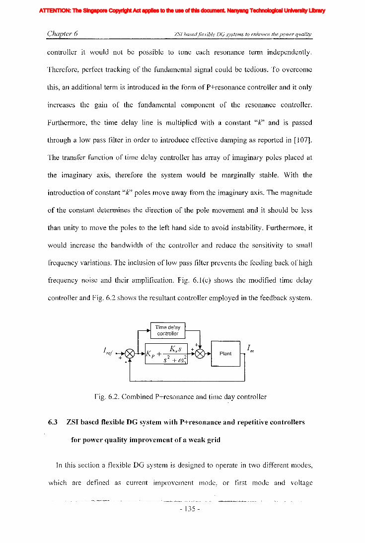
Chapter 6 ZSI basedflexible DG systems to enhance the power quality
controller it would not be possible to tune each resonance term independently.
Therefore, perfect tracking of the fundamental signal could be tedious. To overcome
this, an additional tenn is introduced in the form of P+resonance controller and it only
increases the gain of the fundamental component of the resonance controller.
Furthermore, the time delay line is multiplied with a constant "J(' and is passed
through a low pass filter in order to introduce effective damping as reported in [107].
The transfer function of time delay controller has array of imaginary poles placed at
the imaginary axis, therefore the system would be marginally stable. With the
introduction of constant "k" poles move away from the imaginary axis. The magnitude
of the constant determines the direction of the pole movement and it should be less
than unity to move the poles to the left hand side to avoid instability. Furthermore, it
would increase the bandwidth of the controller and reduce the sensitivity to small
frequency variations. The inclusion of low pass filter prevents the feeding back of high
frequency noise and their amplification. Fig. 6.1 (c) shows the modified time delay
controller and Fig. 6.2 shows the resultant controller employed in the feedback system.
Plant
Fig. 6.2. Combined P+resonance and time day controller
6.3 ZSI based flexible DG system with P+resonance and repetitive controllers
for power quality improvement of a weak grid
In this section a flexible DG system is designed to operate in two different modes,
which are defined as current improvement mode, or first lTIode and voltage
- 135 -
Iiq
Iod
Ioq
I odq
I max
1,Ie, Ici,Ic2IDC
IL_m
I MPP
IpvI scITHD
IzI Zn
lap*lap
Ia,Ip,IoIa *, Ip*,10*
Iah,Iphlin
12n
I;
afJ axis currentafJ axis reference currentafJO axis current componentsafJO axis reference current componentsafJ axis harmonic current componentsNeutral current of inverter 1Neutral current of inverter 2Zero sequence reference current
Average Z-source inductor currentPerturbed Z-source inductor current
Perturbed load currentConstantGain factor of fifth harmonics filterGain factor of seventh harmonics filterGain factor of eleventh harmonics filterDC side controller proportional gain of PI controllerDC side controller integral gain of PI controllerGain of the inverterIntegral gain of PI controller in current controllerGain of the hth resonance filterProportional gain of AC side inner loop controllerProportional gain of PI controller in current controllerProportional gain of zero sequence resonance controllerIntegral gain of the resonance controllerIntegral gain of the zero sequence resonance controllerIntegral gain of the hth resonance controllerProportional gain of AC side PI controllerIntegral gain of the AC side PI controllerMultiplying factor for harmonics eliminationDC side filter inductanceLoad inductanceNeutral inductanceGrid inductanceLeakage inductance of transformer
XVII
ATTENTION: The Singapore Copyright Act applies to the use of this document. Nanyang Technological University Library

Chapter 6 ZSI basedjlexible DG systems to enhance the power quality
improvement mode, or second mode. In the first mode, it would inject the desired
amount of power into the grid, and the controllers are designed to reduce the
harmonics in the injecting current. In the second mode, if the inverter is not operating
its full capacity, the remaining capacity is utilized to improve the voltage THD at the
connecting bus. In both modes, controllers are designed in the stationary reference
frame and combined controller designed in the previous section (6.2) is employed. The
designed controllers are tested on the ZSI shown in Fig. 6.3.
L
Fig. 6.3. Grid connected ZSI topology
6.3.1 Principle of operation
There are numerous control methods that can be used with DG systems to support
different aspects of power quality improvement such as harmonic mitigation, sag
compensation and reactive power controlling, etc. However, focus of this section is
limited to harmonic mitigation. Fig. 6.4 (a) shows the single line diagram of the
consideredDG system, where a typical DG inverter, a linear load and a non-linear
load are connected to the grid at the pec. The presence of non-linear load would
distort the voltage at PCC and also it would distort the injecting current of the inverter.
Two operating modes are considered to address the power quality issues present with
considered circuit given in Fig. 6.4(a). When the DG power source operated in full
capacity or in other words the systelTI demands maxiJTIum power, the inverters are
- 136-
Iiq
Iod
Ioq
I odq
I max
1,Ie, Ici,Ic2IDC
IL_m
I MPP
IpvI scITHD
IzI Zn
lap*lap
Ia,Ip,IoIa *, Ip*,10*
Iah,Iphlin
12n
I;
afJ axis currentafJ axis reference currentafJO axis current componentsafJO axis reference current componentsafJ axis harmonic current componentsNeutral current of inverter 1Neutral current of inverter 2Zero sequence reference current
Average Z-source inductor currentPerturbed Z-source inductor current
Perturbed load currentConstantGain factor of fifth harmonics filterGain factor of seventh harmonics filterGain factor of eleventh harmonics filterDC side controller proportional gain of PI controllerDC side controller integral gain of PI controllerGain of the inverterIntegral gain of PI controller in current controllerGain of the hth resonance filterProportional gain of AC side inner loop controllerProportional gain of PI controller in current controllerProportional gain of zero sequence resonance controllerIntegral gain of the resonance controllerIntegral gain of the zero sequence resonance controllerIntegral gain of the hth resonance controllerProportional gain of AC side PI controllerIntegral gain of the AC side PI controllerMultiplying factor for harmonics eliminationDC side filter inductanceLoad inductanceNeutral inductanceGrid inductanceLeakage inductance of transformer
XVII
ATTENTION: The Singapore Copyright Act applies to the use of this document. Nanyang Technological University Library
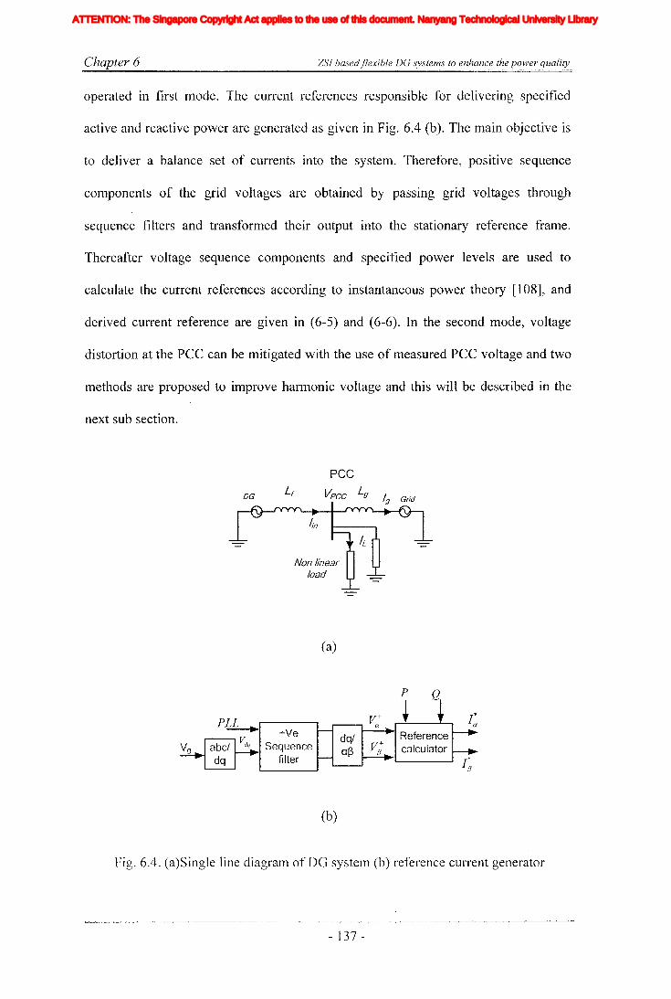
Chapter 6 ZSJ basedflexible DG systems to enhance the power quality
operated in first mode. The current references responsible for delivering specified
active and reactive power are generated as given in Fig. 6.4 (b). The main objective is
to deliver a balance set of currents into the system. Therefore, positive sequence
components of the grid voltages are obtained by passing grid voltages through
sequence filters and transfonned their output into the stationary reference frame.
Thereafter voltage sequence components and specified power levels are used to
calculate the current references according to instantaneous power theory [108], and
derived current reference are given in (6-5) and (6-6). In the second mode, voltage
distortion at the pee can be mitigated with the use of measured pee voltage and two
methods are proposed to improve hannonic voltage and this will be described in the
next sub section.
DG Lr
peevpcc Lg Ig Grid
Non linearload
(a)
+VeSequence
filter
(b)
dq/of)
P Q
Fig. 6.4. (a)Single line diagram of DG system (b) reference current generator
- 137 -
Iiq
Iod
Ioq
I odq
I max
1,Ie, Ici,Ic2IDC
IL_m
I MPP
IpvI scITHD
IzI Zn
lap*lap
Ia,Ip,IoIa *, Ip*,10*
Iah,Iphlin
12n
I;
afJ axis currentafJ axis reference currentafJO axis current componentsafJO axis reference current componentsafJ axis harmonic current componentsNeutral current of inverter 1Neutral current of inverter 2Zero sequence reference current
Average Z-source inductor currentPerturbed Z-source inductor current
Perturbed load currentConstantGain factor of fifth harmonics filterGain factor of seventh harmonics filterGain factor of eleventh harmonics filterDC side controller proportional gain of PI controllerDC side controller integral gain of PI controllerGain of the inverterIntegral gain of PI controller in current controllerGain of the hth resonance filterProportional gain of AC side inner loop controllerProportional gain of PI controller in current controllerProportional gain of zero sequence resonance controllerIntegral gain of the resonance controllerIntegral gain of the zero sequence resonance controllerIntegral gain of the hth resonance controllerProportional gain of AC side PI controllerIntegral gain of the AC side PI controllerMultiplying factor for harmonics eliminationDC side filter inductanceLoad inductanceNeutral inductanceGrid inductanceLeakage inductance of transformer
XVII
ATTENTION: The Singapore Copyright Act applies to the use of this document. Nanyang Technological University Library
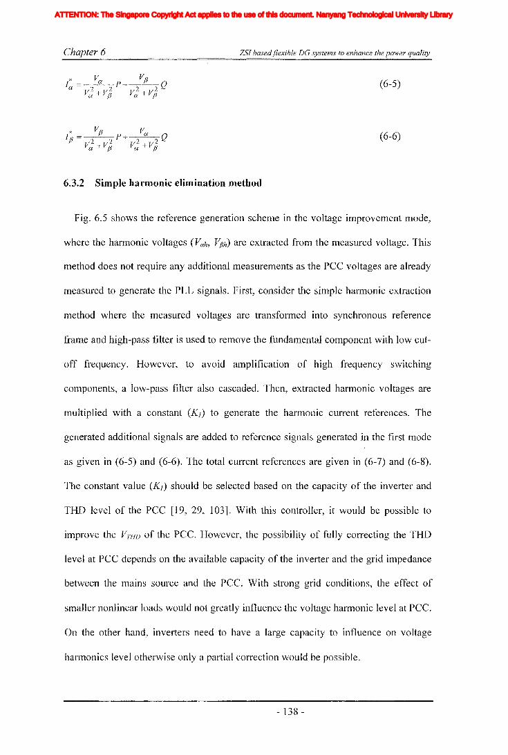
Chapter 6 ZSI basedjlexible DG systems to enhance the power quality
(6-5)
(6-6)
6.3.2 Simple harmonic elimination method
Fig. 6.5 shows the reference generation scheme in the voltage improvement mode,
where the harmonic voltages (Vah, VjJh) are extracted from the measured voltage. This
method does not require any additional measurements as the pee voltages are already
measured to generate the PLL signals. First, consider the simple harmonic extraction
method where the measured voltages are transformed into synchronous reference
frame and high-pass filter is used to remove the fundamental component with low cut-
off frequency. I-Iowever, to avoid amplification of high frequency switching
components, a low-pass filter also cascaded. Then, extracted harmonic voltages are
multiplied with a constant (Kj ) to generate the harmonic current references. The
generated additional signals are added to reference signals generated in the first mode
as given in (6-5) and (6-6). The total current references are given in (6-7) and (6-8).
The constant value (Kj) should be selected based on the capacity of the inverter and
THD level of the PCC [19, 29, 103]. With this controller, it would be possible to
improve the VTHD of the PCC. However, the possibility of fully correcting the THD
level at PCC depends on the available capacity of the inverter and the grid impedance
between the mains source and the PCC. With strong grid conditions, the effect of
smaller nonlinear loads would not greatly influence the voltage harmonic level at PCC.
On the other hand, inverters need to have a large capacity to influence on voltage
hannonics level otherwise only a partial correction would be possible.
- 138 -
Iiq
Iod
Ioq
I odq
I max
1,Ie, Ici,Ic2IDC
IL_m
I MPP
IpvI scITHD
IzI Zn
lap*lap
Ia,Ip,IoIa *, Ip*,10*
Iah,Iphlin
12n
I;
afJ axis currentafJ axis reference currentafJO axis current componentsafJO axis reference current componentsafJ axis harmonic current componentsNeutral current of inverter 1Neutral current of inverter 2Zero sequence reference current
Average Z-source inductor currentPerturbed Z-source inductor current
Perturbed load currentConstantGain factor of fifth harmonics filterGain factor of seventh harmonics filterGain factor of eleventh harmonics filterDC side controller proportional gain of PI controllerDC side controller integral gain of PI controllerGain of the inverterIntegral gain of PI controller in current controllerGain of the hth resonance filterProportional gain of AC side inner loop controllerProportional gain of PI controller in current controllerProportional gain of zero sequence resonance controllerIntegral gain of the resonance controllerIntegral gain of the zero sequence resonance controllerIntegral gain of the hth resonance controllerProportional gain of AC side PI controllerIntegral gain of the AC side PI controllerMultiplying factor for harmonics eliminationDC side filter inductanceLoad inductanceNeutral inductanceGrid inductanceLeakage inductance of transformer
XVII
ATTENTION: The Singapore Copyright Act applies to the use of this document. Nanyang Technological University Library

C-Yhapter 6 ZSI basedflexible DG systems to enhance the power quality
P Q
+VeSequence
filter
HighL..-.--I.. pass
~/q filter
dqlaf3
dqlaf3
Fig. 6.5. Simple current reference generations
(6-7)
(6-8)
However, proposed ancillary servIce should not be a hindrance for the basic
function of delivering active and reactive power. Therefore, the current references
have to be generated to deliver the desired active power and reactive power and then,
additional reference signals are to be added with the original current references to
improve the power quality.
6.3.3 Improved harmonic elimination method
In the previous section, hannonic reference currents are generated using extracted
hannonic voltages with high pass filters which enables fast transient response. Similar
methods are very commonly applied in APF systems [47]. However, the phase error
introduced by the high pass filter could introduce a phase delay in the higher harmonic
components which would influence the correct compensation of harmonics [109]. But,
with the restricted capacity of inverters it would not be the most effective way of
harmonic compensation.
- 139 -
Iiq
Iod
Ioq
I odq
I max
1,Ie, Ici,Ic2IDC
IL_m
I MPP
IpvI scITHD
IzI Zn
lap*lap
Ia,Ip,IoIa *, Ip*,10*
Iah,Iphlin
12n
I;
afJ axis currentafJ axis reference currentafJO axis current componentsafJO axis reference current componentsafJ axis harmonic current componentsNeutral current of inverter 1Neutral current of inverter 2Zero sequence reference current
Average Z-source inductor currentPerturbed Z-source inductor current
Perturbed load currentConstantGain factor of fifth harmonics filterGain factor of seventh harmonics filterGain factor of eleventh harmonics filterDC side controller proportional gain of PI controllerDC side controller integral gain of PI controllerGain of the inverterIntegral gain of PI controller in current controllerGain of the hth resonance filterProportional gain of AC side inner loop controllerProportional gain of PI controller in current controllerProportional gain of zero sequence resonance controllerIntegral gain of the resonance controllerIntegral gain of the zero sequence resonance controllerIntegral gain of the hth resonance controllerProportional gain of AC side PI controllerIntegral gain of the AC side PI controllerMultiplying factor for harmonics eliminationDC side filter inductanceLoad inductanceNeutral inductanceGrid inductanceLeakage inductance of transformer
XVII
ATTENTION: The Singapore Copyright Act applies to the use of this document. Nanyang Technological University Library
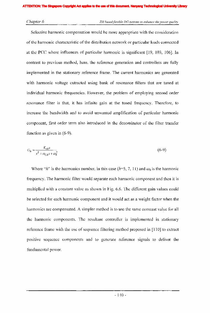
Chapter 6 ZSI basedflexible DG systems to enhance the power quality
Selective harmonic compensation would be more appropriate with the consideration
of the harmonic characteristic of the distribution network or particular loads connected
at the PCC where influences of particular harmonic is significant [19, 103, 106]. In
contrast to previous method, here, the reference generation and controllers are fully
implemented in the stationary reference frame. The current harmonics are generated
with harmonic voltage extracted using bank of resonance filters that are tuned at
individual harmonic frequencies. However, the problem of employing second order
resonance filter is that, it has infinite gain at the tuned frequency. Therefore, to
increase the bandwidth and to avoid unwanted amplification of particular harmonic
component, first order term also introduced in the denominator of the filter transfer
function as given in (6-9).
(6-9)
Where "h" is the hannonics number, in this case (h=5, 7, 11) and Wh is the harmonic
frequency. The harmonic filter would separate each harmonic component and then it is
multiplied with a constant value as shown in Fig. 6.6. The different gain values could
be selected for each harmonic component and it would act as a weight factor when the
harmonics are compensated. A simpler method is to use the same constant value for all
the harmonic components. The resultant controller is implemented in stationary
reference frame with the use of sequence filtering lnethod proposed in [110] to extract
positive sequence components and to generate reference signals to deliver the
fundalnental power.
- 140 -
Iiq
Iod
Ioq
I odq
I max
1,Ie, Ici,Ic2IDC
IL_m
I MPP
IpvI scITHD
IzI Zn
lap*lap
Ia,Ip,IoIa *, Ip*,10*
Iah,Iphlin
12n
I;
afJ axis currentafJ axis reference currentafJO axis current componentsafJO axis reference current componentsafJ axis harmonic current componentsNeutral current of inverter 1Neutral current of inverter 2Zero sequence reference current
Average Z-source inductor currentPerturbed Z-source inductor current
Perturbed load currentConstantGain factor of fifth harmonics filterGain factor of seventh harmonics filterGain factor of eleventh harmonics filterDC side controller proportional gain of PI controllerDC side controller integral gain of PI controllerGain of the inverterIntegral gain of PI controller in current controllerGain of the hth resonance filterProportional gain of AC side inner loop controllerProportional gain of PI controller in current controllerProportional gain of zero sequence resonance controllerIntegral gain of the resonance controllerIntegral gain of the zero sequence resonance controllerIntegral gain of the hth resonance controllerProportional gain of AC side PI controllerIntegral gain of the AC side PI controllerMultiplying factor for harmonics eliminationDC side filter inductanceLoad inductanceNeutral inductanceGrid inductanceLeakage inductance of transformer
XVII
ATTENTION: The Singapore Copyright Act applies to the use of this document. Nanyang Technological University Library
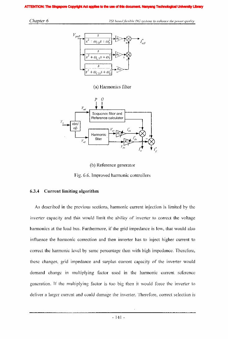
Chapter 6 ZSJ basedjlexible DG systems to enhance the pow,er quality
(a) Harmonics filter
p Q
Sequence filter andReference calculator t----....,
Harmonicfilter
(b) Reference generator
Fig. 6.6. Improved harmonic controllers
6.3.4 Current limiting algorithm
As described in the previous sections, harmonic current injection is limited by the
inverter capacity and this would limit the ability of inverter to correct the voltage
harmonics at the load bus. Furthermore, if the grid impedance is low, that would also
influence the harmonic correction and then inverter has to inject higher current to
correct the harmonic level by same percentage than with high impedance. Therefore,
these changes, grid impedance and surplus current capacity of the inverter would
demand change in multiplying factor used in the harmonic ourrent reference
generation. If the multiplying factor is too big then it would force the inverter to
deliver a larger current and could damage the inverter. Therefore, correct selection is
- 141 -
Iiq
Iod
Ioq
I odq
I max
1,Ie, Ici,Ic2IDC
IL_m
I MPP
IpvI scITHD
IzI Zn
lap*lap
Ia,Ip,IoIa *, Ip*,10*
Iah,Iphlin
12n
I;
afJ axis currentafJ axis reference currentafJO axis current componentsafJO axis reference current componentsafJ axis harmonic current componentsNeutral current of inverter 1Neutral current of inverter 2Zero sequence reference current
Average Z-source inductor currentPerturbed Z-source inductor current
Perturbed load currentConstantGain factor of fifth harmonics filterGain factor of seventh harmonics filterGain factor of eleventh harmonics filterDC side controller proportional gain of PI controllerDC side controller integral gain of PI controllerGain of the inverterIntegral gain of PI controller in current controllerGain of the hth resonance filterProportional gain of AC side inner loop controllerProportional gain of PI controller in current controllerProportional gain of zero sequence resonance controllerIntegral gain of the resonance controllerIntegral gain of the zero sequence resonance controllerIntegral gain of the hth resonance controllerProportional gain of AC side PI controllerIntegral gain of the AC side PI controllerMultiplying factor for harmonics eliminationDC side filter inductanceLoad inductanceNeutral inductanceGrid inductanceLeakage inductance of transformer
XVII
ATTENTION: The Singapore Copyright Act applies to the use of this document. Nanyang Technological University Library

Chapter 6 ZSI basedflexible DG systems to enhance the power quality
essential. This section proposes a method that could be used to calculate the required
gain factor. Fig. 6.7 shows the block diagram representation of the proposed current
limiting algorithm that is embedded in the reference current generator.
P Q
Moving windowRMS calculator
Fig. 6.7. Reference generator with embedded current limiter
Generally, the rms value of the power controller current or voltage is calculated in
synchronous reference frame [21, 30]. In the synchronous reference frame, the
fundamental component of three phase signals would be a DC quantity. However, with
the presence of harmonics and unbalance components, the calculated rms would have
a ripple component. If such a simple rms calculation is employed in the current limiter
then that would result in imposed ripple in multiplying factor that could lead to have a
more distortions in the voltage. Therefore, rms values are calculated using moving
window rms calculator. Where the rms value is calculated for acquired samples of
defined length equal to half of the fundamental period and each time a new sample is
taken, the oldest sample is removed. Thereby, the rms value is moved with the time
and the generated rms value is free from ripple components. Then moving window
rms value of Ineasured current is calculated and it is compared with the Inaxinlum
current limit. The error signal generated in a cOlnpensator is controlled with a PI
controller to get the value of kJ dynamically. The use of PI controller would change the
- 142 -
Iiq
Iod
Ioq
I odq
I max
1,Ie, Ici,Ic2IDC
IL_m
I MPP
IpvI scITHD
IzI Zn
lap*lap
Ia,Ip,IoIa *, Ip*,10*
Iah,Iphlin
12n
I;
afJ axis currentafJ axis reference currentafJO axis current componentsafJO axis reference current componentsafJ axis harmonic current componentsNeutral current of inverter 1Neutral current of inverter 2Zero sequence reference current
Average Z-source inductor currentPerturbed Z-source inductor current
Perturbed load currentConstantGain factor of fifth harmonics filterGain factor of seventh harmonics filterGain factor of eleventh harmonics filterDC side controller proportional gain of PI controllerDC side controller integral gain of PI controllerGain of the inverterIntegral gain of PI controller in current controllerGain of the hth resonance filterProportional gain of AC side inner loop controllerProportional gain of PI controller in current controllerProportional gain of zero sequence resonance controllerIntegral gain of the resonance controllerIntegral gain of the zero sequence resonance controllerIntegral gain of the hth resonance controllerProportional gain of AC side PI controllerIntegral gain of the AC side PI controllerMultiplying factor for harmonics eliminationDC side filter inductanceLoad inductanceNeutral inductanceGrid inductanceLeakage inductance of transformer
XVII
ATTENTION: The Singapore Copyright Act applies to the use of this document. Nanyang Technological University Library
Chapter 6 ZSJ basedjlexible DG systems to enhance the power quality
gain factor, when the other parameters are changed so that the unused capacity is fully
utilized and the damage to the inverter by high currents is prevented.
6.4 Modeling of ZSI controller design
In chapter 4 and [18] a stand-alone type DO system is proposed where ZSI is
modeled as a combination of fast and slow systems observing the existence of time
scale decoupling of two systems. Separate controllers are designed for the AC and DC
side sub systems. The AC-side controllers are designed in the rotating reference frame
and an indirect controller is designed for the DC-side that would maintain constant
supply voltage to the inverter bridge. In this context, AC-side controllers are designed
in the 'stationary reference frame. The DC-side controllers are designed based on the
derived small signal model of the Z-source impedance network. The proposed
controller is similar to the DC-side controller presented in chapter 4 where inductor
current and voltage across capacitor are eluployed in the controller. However, the
output voltage of the capacitor is directly controlled instead of using it to predict the
supply voltage in the present study.
6.4.1 Mathematical model and AC-side controller
The AC-side controllers are designed to operate in two different modes, the current
control mode (first mode) and the voltage control mode (second mode). Also the AC
side controllers consist of two parts, namely, reference generation and current
controlling. As discussed in the previous section, when the inverter operates in the
current control luode, it would inject a quality sine wave with reduced harmonics. The
system is put into this mode when the renewable source generates large quantity of
energy. In the voltage control mode, in addition to active power injection, the voltage
quality at the pee would also be enhanced. The operational mode is simply selected
- 143 -
Iiq
Iod
Ioq
I odq
I max
1,Ie, Ici,Ic2IDC
IL_m
I MPP
IpvI scITHD
IzI Zn
lap*lap
Ia,Ip,IoIa *, Ip*,10*
Iah,Iphlin
12n
I;
afJ axis currentafJ axis reference currentafJO axis current componentsafJO axis reference current componentsafJ axis harmonic current componentsNeutral current of inverter 1Neutral current of inverter 2Zero sequence reference current
Average Z-source inductor currentPerturbed Z-source inductor current
Perturbed load currentConstantGain factor of fifth harmonics filterGain factor of seventh harmonics filterGain factor of eleventh harmonics filterDC side controller proportional gain of PI controllerDC side controller integral gain of PI controllerGain of the inverterIntegral gain of PI controller in current controllerGain of the hth resonance filterProportional gain of AC side inner loop controllerProportional gain of PI controller in current controllerProportional gain of zero sequence resonance controllerIntegral gain of the resonance controllerIntegral gain of the zero sequence resonance controllerIntegral gain of the hth resonance controllerProportional gain of AC side PI controllerIntegral gain of the AC side PI controllerMultiplying factor for harmonics eliminationDC side filter inductanceLoad inductanceNeutral inductanceGrid inductanceLeakage inductance of transformer
XVII
ATTENTION: The Singapore Copyright Act applies to the use of this document. Nanyang Technological University Library

Chapter 6 ZSI basedjlexible DG systems to enhance the power quality
by adjusting the variable gain (Kl). When the system operates in full capacity the gain
(Kl) is adjusted to zero, thereby putting the inverter into current control mode. When
the system is operated below the rated capacity, the gain (Kl) needs to be changed to
improve the VTHD while observing the limits of the inverter system. For controlling the
inverter, the output current and voltage at pee are measured.
Having designed the reference generation in the previous section, now the task is to
design the controller. Before designing the controller, it would be necessary to obtain
the lnathematical model of the AC-side sub system. Fig. 6.3 shows the circuit diagram
of the considered topology. Then, by applying KVL to the AC-side of the inverter, for
each x phase (x =a, b, c), equation (6-10) can be obtained. Where p=d/dt, output
voltage of inverter vxm=[vamJ Vbm, vem], the grid voltage Vgx=[VgaJ Vgb, vge], vgm =common
mode voltage and ix=[ia, h, ie] the output current of the inverter.
(6-10)
However, by noting a balanced system, l:vxm=Oand LVgx=O (assuming the supply
side harmonics are balanced for simplicity of controller design) common mode voltage
can be written as vgm=Vs *(da+db+de)/3 where Vs is the output voltage of Z-source
network and "dx" is the switching duty ratio. Then, by applying the Clark's
transformation given in (6-11), equations (6-12) and (6-13) can be obtained.
(6-1 1)
(6-12)
(6-]3)
- 144 -
Iiq
Iod
Ioq
I odq
I max
1,Ie, Ici,Ic2IDC
IL_m
I MPP
IpvI scITHD
IzI Zn
lap*lap
Ia,Ip,IoIa *, Ip*,10*
Iah,Iphlin
12n
I;
afJ axis currentafJ axis reference currentafJO axis current componentsafJO axis reference current componentsafJ axis harmonic current componentsNeutral current of inverter 1Neutral current of inverter 2Zero sequence reference current
Average Z-source inductor currentPerturbed Z-source inductor current
Perturbed load currentConstantGain factor of fifth harmonics filterGain factor of seventh harmonics filterGain factor of eleventh harmonics filterDC side controller proportional gain of PI controllerDC side controller integral gain of PI controllerGain of the inverterIntegral gain of PI controller in current controllerGain of the hth resonance filterProportional gain of AC side inner loop controllerProportional gain of PI controller in current controllerProportional gain of zero sequence resonance controllerIntegral gain of the resonance controllerIntegral gain of the zero sequence resonance controllerIntegral gain of the hth resonance controllerProportional gain of AC side PI controllerIntegral gain of the AC side PI controllerMultiplying factor for harmonics eliminationDC side filter inductanceLoad inductanceNeutral inductanceGrid inductanceLeakage inductance of transformer
XVII
ATTENTION: The Singapore Copyright Act applies to the use of this document. Nanyang Technological University Library

Chapter 6 ZSI basedflexible DC systems to enhance the power quality
where vgo:, Vo:m, io:, and vgfJ, vmfJ, ifJ are a and fJ axis components of the grid voltage,
inverter output voltage and inverter output current respectively and ".f " can be any
electrical parameter. In the grid connected mode, the current quality is determined by
the voltage quality of the system because if the PCC voltage is polluted and it would
make the injecting currents also to be distorted. From (6-12) and (6-13), the block
diagram representation of the system is obtained as in Fig. 6.8. Where KIC is the gain
of the inverter and measured grid current is controlled in closed loop manner using the
combined controller designed in the previous section.
Fig. 6.8. AC-side controller
6.4.2 DC-side controller
The DC-side controller is designed based on the small signal model obtained in
chapter 4 and also presented in [18]. It is similar to the DC-side controller presented in
chapter 4 with the exception that the output voltage of the capacitor is directly
controlled instead of using it to predict the supply voltage to the inverters (see Fig.
6.9). This design allows better utilization of boosted voltage and also it reduces the
voltage stress applied on the switches. In method presented in chapter 4, the voltage is
boosted to obtain a constant supply voltage to the inverter and modulation index is
kept almost constant and is changed only during the transients and shoot-through is
- 145 -
Iiq
Iod
Ioq
I odq
I max
1,Ie, Ici,Ic2IDC
IL_m
I MPP
IpvI scITHD
IzI Zn
lap*lap
Ia,Ip,IoIa *, Ip*,10*
Iah,Iphlin
12n
I;
afJ axis currentafJ axis reference currentafJO axis current componentsafJO axis reference current componentsafJ axis harmonic current componentsNeutral current of inverter 1Neutral current of inverter 2Zero sequence reference current
Average Z-source inductor currentPerturbed Z-source inductor current
Perturbed load currentConstantGain factor of fifth harmonics filterGain factor of seventh harmonics filterGain factor of eleventh harmonics filterDC side controller proportional gain of PI controllerDC side controller integral gain of PI controllerGain of the inverterIntegral gain of PI controller in current controllerGain of the hth resonance filterProportional gain of AC side inner loop controllerProportional gain of PI controller in current controllerProportional gain of zero sequence resonance controllerIntegral gain of the resonance controllerIntegral gain of the zero sequence resonance controllerIntegral gain of the hth resonance controllerProportional gain of AC side PI controllerIntegral gain of the AC side PI controllerMultiplying factor for harmonics eliminationDC side filter inductanceLoad inductanceNeutral inductanceGrid inductanceLeakage inductance of transformer
XVII
ATTENTION: The Singapore Copyright Act applies to the use of this document. Nanyang Technological University Library
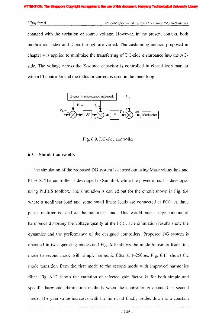
Chapter 6 ZSI basedflexible DG systems to enhance the power quality
changed with the variation of source voltage. However, in the present context, both
modulation index and shoot-through are varied. The cushioning method proposed in
chapter 4 is applied to minimize the transferring of DC-side disturbance into the AC
side. The voltage across the Z-source capacitor is controlled in closed loop manner
with a PI controller and the inductor current is used in the inner loop.
Fig. 6.9. DC-side controller
6.5 Simulation results
The simulation of the proposed DG system is carried out using Matlab/Simulink and
PLECS. The controller is developed in Simulink while the power circuit is developed
using PLECS toolbox. The simulation is carried out for the circuit shown in Fig. 6.4
where a nonlinear load and some small linear loads are connected at PCC. A three
phase rectifier is used as the nonlinear load. This would inject large amount of
harmonics distorting the voltage quality at the PCC. The simulation results show the
dynamics and the performance of the designed controllers. Proposed DG system is
operated in two operating modes and Fig. 6.10 shows the mode transition from first
mode to second mode with simple harmonic filter at t=2501TIS. Fig. 6.11 shows the
mode transition from the first lTIode to the second mode with improved harmonics
filter. Fig. 6.12 shows the variation of selected gain factor kl for both simple and
specific harmonic eliminatio~ methods when the controller is operated in second
ITIode. The gain value increases with the time and finally settles down to a constant
- 146 -
Iiq
Iod
Ioq
I odq
I max
1,Ie, Ici,Ic2IDC
IL_m
I MPP
IpvI scITHD
IzI Zn
lap*lap
Ia,Ip,IoIa *, Ip*,10*
Iah,Iphlin
12n
I;
afJ axis currentafJ axis reference currentafJO axis current componentsafJO axis reference current componentsafJ axis harmonic current componentsNeutral current of inverter 1Neutral current of inverter 2Zero sequence reference current
Average Z-source inductor currentPerturbed Z-source inductor current
Perturbed load currentConstantGain factor of fifth harmonics filterGain factor of seventh harmonics filterGain factor of eleventh harmonics filterDC side controller proportional gain of PI controllerDC side controller integral gain of PI controllerGain of the inverterIntegral gain of PI controller in current controllerGain of the hth resonance filterProportional gain of AC side inner loop controllerProportional gain of PI controller in current controllerProportional gain of zero sequence resonance controllerIntegral gain of the resonance controllerIntegral gain of the zero sequence resonance controllerIntegral gain of the hth resonance controllerProportional gain of AC side PI controllerIntegral gain of the AC side PI controllerMultiplying factor for harmonics eliminationDC side filter inductanceLoad inductanceNeutral inductanceGrid inductanceLeakage inductance of transformer
XVII
ATTENTION: The Singapore Copyright Act applies to the use of this document. Nanyang Technological University Library
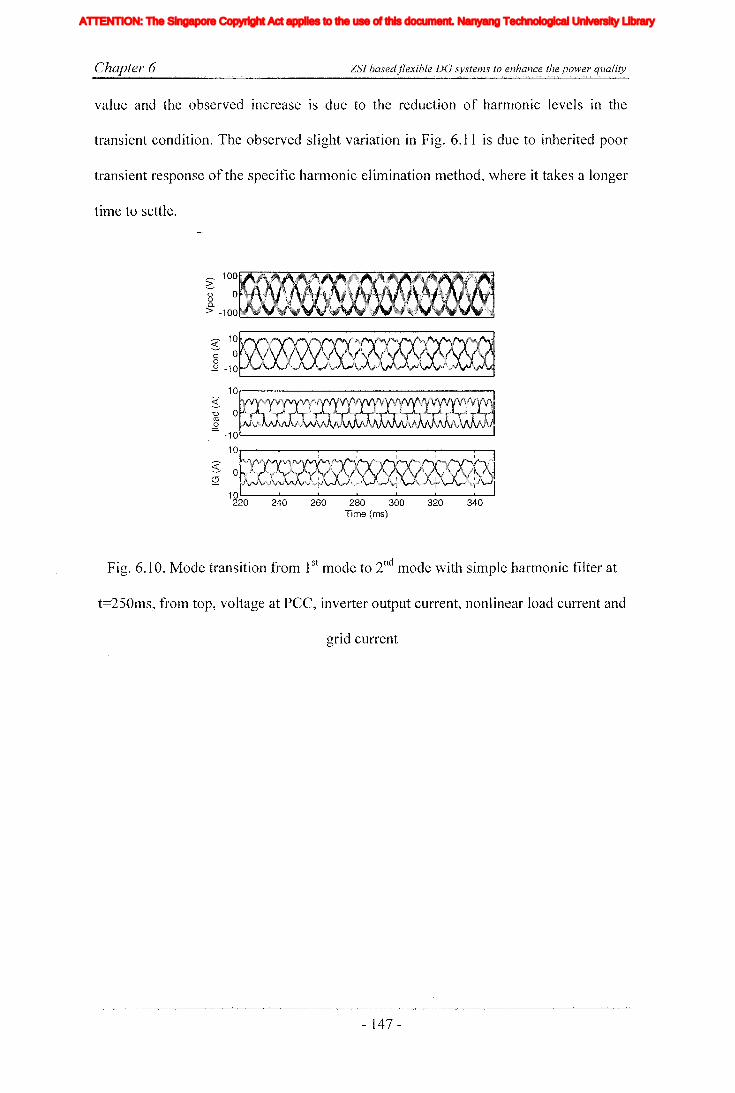
Chapter 6 ZSl basedflexible DG systems to enhance the power quality
value and the observed increase is due to the reduction of harmonic levels in the
transient condition. The observed slight variation in Fig. 6.11 is due to inherited poor
transient response of the specific harmonic elimination method, where it takes a longer
time to settle.
,.-.. 100Gg 00-
> -1 00 '--"'---"---:;;;.--=---=--~..;..;;.......;:..........;;;'----="-.......;;.........::..-...::..-.;;;.........;:;;.....-.,;;:'---"'---=----'"
« 10
~ 0o
.s:? -10
240 260 280 300Time (ms)
320 340
Fig. 6.10. Mode transition from 1st mode to 2nd mode with simple harmonic filter at
t=2501TIS, from top, voltage at PCC, inverter output current, nonlinear load current and
grid current
- 147 -
Iiq
Iod
Ioq
I odq
I max
1,Ie, Ici,Ic2IDC
IL_m
I MPP
IpvI scITHD
IzI Zn
lap*lap
Ia,Ip,IoIa *, Ip*,10*
Iah,Iphlin
12n
I;
afJ axis currentafJ axis reference currentafJO axis current componentsafJO axis reference current componentsafJ axis harmonic current componentsNeutral current of inverter 1Neutral current of inverter 2Zero sequence reference current
Average Z-source inductor currentPerturbed Z-source inductor current
Perturbed load currentConstantGain factor of fifth harmonics filterGain factor of seventh harmonics filterGain factor of eleventh harmonics filterDC side controller proportional gain of PI controllerDC side controller integral gain of PI controllerGain of the inverterIntegral gain of PI controller in current controllerGain of the hth resonance filterProportional gain of AC side inner loop controllerProportional gain of PI controller in current controllerProportional gain of zero sequence resonance controllerIntegral gain of the resonance controllerIntegral gain of the zero sequence resonance controllerIntegral gain of the hth resonance controllerProportional gain of AC side PI controllerIntegral gain of the AC side PI controllerMultiplying factor for harmonics eliminationDC side filter inductanceLoad inductanceNeutral inductanceGrid inductanceLeakage inductance of transformer
XVII
ATTENTION: The Singapore Copyright Act applies to the use of this document. Nanyang Technological University Library

Chapter 6 ZSI basedflexible DG systems to enhance the power quality
,...... 100G8 0a..> -100 """--"'---'----"'---'--_.;.;.......;;;
~ 10-; 0o.2 -10 .
10r----------------~
340320240 260 280 300Time (ms)
-10~------------------'
10r-----.--_r-----,--_r---.,..---.r----o
g 0S2 i
_10l.--_--L-__l.---_--L-__l.---_--L-__L..-.--J
220
Fig. 6.11. Mode transition from 1st mode to 2nd mode with specific harmonic
elimination method at t=250ms, from top, voltage at PCC, inverter output current,
nonlinear load current and grid current
1.5 ·····,················1··················1·········:-· :..
~ 1 -----:---------i---------:------- ;.-
0.5 ----+------ '
250 300 350 400 450 500 550 600Time (ms)
Fig. 6.12. Gain factor kl for simple and specific harmonic elimination methods, mode
transition from 1st mode to 2nd mode at t=250ms.
Figs 6.13 to Fig. 6.16 show harmonic spectrums for first mode and second mode
ITIodes. In the second lTIode of operation two harmonic selection methods are used and
they are named as V1 control ITIode and V2 control ITIode. The sinlulations are done
- 148 -
Iiq
Iod
Ioq
I odq
I max
1,Ie, Ici,Ic2IDC
IL_m
I MPP
IpvI scITHD
IzI Zn
lap*lap
Ia,Ip,IoIa *, Ip*,10*
Iah,Iphlin
12n
I;
afJ axis currentafJ axis reference currentafJO axis current componentsafJO axis reference current componentsafJ axis harmonic current componentsNeutral current of inverter 1Neutral current of inverter 2Zero sequence reference current
Average Z-source inductor currentPerturbed Z-source inductor current
Perturbed load currentConstantGain factor of fifth harmonics filterGain factor of seventh harmonics filterGain factor of eleventh harmonics filterDC side controller proportional gain of PI controllerDC side controller integral gain of PI controllerGain of the inverterIntegral gain of PI controller in current controllerGain of the hth resonance filterProportional gain of AC side inner loop controllerProportional gain of PI controller in current controllerProportional gain of zero sequence resonance controllerIntegral gain of the resonance controllerIntegral gain of the zero sequence resonance controllerIntegral gain of the hth resonance controllerProportional gain of AC side PI controllerIntegral gain of the AC side PI controllerMultiplying factor for harmonics eliminationDC side filter inductanceLoad inductanceNeutral inductanceGrid inductanceLeakage inductance of transformer
XVII
ATTENTION: The Singapore Copyright Act applies to the use of this document. Nanyang Technological University Library
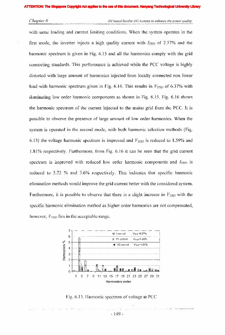
Chapter 6 ZSl basedflexible DC systems to enhance the power quality
with same loading and current limiting conditions. When the system operates in the
first mode, the inverter injects a high quality current with I THD of 2.570/0 and the
harmonic spectrum is given in Fig. 6.15 and all the harmonics comply with the grid
connecting standards. This performance is achieved while the PCC voltage is highly
distorted with large amount of harmonics injected from locally connected non linear
load with harmonic spectrum given in Fig. 6.14. This results in VTHD of 6.37% with
dominating low order harmonic components as shown in Fig. 6.15. Fig. 6.16 shows
the harmonic spectrum of the current injected to the mains grid from the pce. It is
possible to observe the presence of large amount of low order hannonics. When the
system is operated in the second mode, with both hannonic selection methods (Fig.
6.13) the voltage harmonic spectrum is improved and VTHD is reduced to 1.59% and
1.81 % respectively. Furthermore, from Fig. 6.16 it can be seen that the grid current
spectrum is improved with reduced low order harmonic components and I THD is
reduced to 5.72 % and 3.60/0 respectively. This indicates that specific harmonic
elimination methods would improve the grid current better with the considered system.
Furthermore, it is possible to observe that there is a slight increase in VTHD with the
specific harmonic elimination method as higher order harmonics are not compensated,
however, V THD lies in the acceptable range.
VTHO=6.37%01 I control
7 , _ ,
6 --t---~------------------------lo Vi control VTHD=i.59%
mil V2 control VTHD=1.81%?f!. 5 --t-----f.n-----·------------------l
t/)'2 4 -t----ltl--------------------IoE 3 -t---..--l'Iil------· .. ·...·-.....-----...·........----·-----..--·-..-·----..-.--....-.--------{~
ctI::r.: 2 -t----lJ.-------------------i
3 5 7 9 11 13 15 17 19 21 23 25 27 29 31
Harmonics order
Fig. 6.13, Harmonic spectrum of voltage at pee
- 149 -
Iiq
Iod
Ioq
I odq
I max
1,Ie, Ici,Ic2IDC
IL_m
I MPP
IpvI scITHD
IzI Zn
lap*lap
Ia,Ip,IoIa *, Ip*,10*
Iah,Iphlin
12n
I;
afJ axis currentafJ axis reference currentafJO axis current componentsafJO axis reference current componentsafJ axis harmonic current componentsNeutral current of inverter 1Neutral current of inverter 2Zero sequence reference current
Average Z-source inductor currentPerturbed Z-source inductor current
Perturbed load currentConstantGain factor of fifth harmonics filterGain factor of seventh harmonics filterGain factor of eleventh harmonics filterDC side controller proportional gain of PI controllerDC side controller integral gain of PI controllerGain of the inverterIntegral gain of PI controller in current controllerGain of the hth resonance filterProportional gain of AC side inner loop controllerProportional gain of PI controller in current controllerProportional gain of zero sequence resonance controllerIntegral gain of the resonance controllerIntegral gain of the zero sequence resonance controllerIntegral gain of the hth resonance controllerProportional gain of AC side PI controllerIntegral gain of the AC side PI controllerMultiplying factor for harmonics eliminationDC side filter inductanceLoad inductanceNeutral inductanceGrid inductanceLeakage inductance of transformer
XVII
ATTENTION: The Singapore Copyright Act applies to the use of this document. Nanyang Technological University Library

Chapter 6 ZSJ basedflexible DG systems to enhance the power quality
35
30
~ 25I/)0 20'c0
E 15-ns:I: 10
5
0
fill! 'control ITHD=27.S%
o V1 control ITHo=34.S%
1m V2 control
3 5 7 9 11 13 15 17 19 21 23 25 27 29 31
Harmonics order
Fig. 6.14. Harmonic spectrum of load current
20 ,-.".-.-._-~ --"_ _._ _ "." - !m." " '''1-c·o···n-..t-r·oI..·..•·.." ·_·~..· -I·T·~H ..O..-=·..2 S·7"0/<·0·· - ,,----.,
18+--------------0- V-1 c-o-nt-ro-'--
ITC-:..:
HO-=--=-17-.3-%----l
16'" ----------1~ 14 ED V2 control . ITHO=19.2%t/)
o 12'co 10Em 8
:::t: 642O-l-""-""'-r""...........,............,...-="'-r""-..........."'-""'-.-....,.."...........,.........-...,....".....................,...--~...,...,...~
3 5 7 9 11 13 15 17 19 21 23 25 27 29 31
Harmonics order
Fig. 6.15. Harmonic spectrUlTI of output current of inverter
25IillJ I control ITHD=22.4%
20'C:f? 0 V1 control ITHD=5.72%VI.~ 15c: Ii1I V2 control0E 10r.-ca:I:
5
03 5 7 9 11 13 15 17 19 21 23 25 27 29 31
Harmonics order
Fig. 6.16. Harmonic spectrum of grid current
Fig. 6.17 shows the DC-side step response of the ZSIwhen it is operated in the
second mode, where the DC input voltage is given a step response to elTIulate the
- ]50 -
Iiq
Iod
Ioq
I odq
I max
1,Ie, Ici,Ic2IDC
IL_m
I MPP
IpvI scITHD
IzI Zn
lap*lap
Ia,Ip,IoIa *, Ip*,10*
Iah,Iphlin
12n
I;
afJ axis currentafJ axis reference currentafJO axis current componentsafJO axis reference current componentsafJ axis harmonic current componentsNeutral current of inverter 1Neutral current of inverter 2Zero sequence reference current
Average Z-source inductor currentPerturbed Z-source inductor current
Perturbed load currentConstantGain factor of fifth harmonics filterGain factor of seventh harmonics filterGain factor of eleventh harmonics filterDC side controller proportional gain of PI controllerDC side controller integral gain of PI controllerGain of the inverterIntegral gain of PI controller in current controllerGain of the hth resonance filterProportional gain of AC side inner loop controllerProportional gain of PI controller in current controllerProportional gain of zero sequence resonance controllerIntegral gain of the resonance controllerIntegral gain of the zero sequence resonance controllerIntegral gain of the hth resonance controllerProportional gain of AC side PI controllerIntegral gain of the AC side PI controllerMultiplying factor for harmonics eliminationDC side filter inductanceLoad inductanceNeutral inductanceGrid inductanceLeakage inductance of transformer
XVII
ATTENTION: The Singapore Copyright Act applies to the use of this document. Nanyang Technological University Library

Chapter 6 ZSI basedjlexible DG systems to enhance the power quality
characteristics of a renewable source. At t=350ms, the input voltage is changed from
240V to 120V and this would act as a disturbance for the system. When the input
voltage (VDc) drops, in order to maintain a constant voltage across a capacitor
(Vc=VDc*(l-Ds)/ (1-2 *Ds)), the shoot-through time (Ds) needs to be increased
therefore the modulation index is reduced. When the output voltage of Z-source
impedance network (Vs=VDc/ (1-2*Ds)) is increased as shown in Fig. 6.17 (top).
However, the Z-source output voltage is slightly disturbed due to the change in the
input voltage and the disturbance may propagate into the AC-side current. This can be
avoided by having sufficient null interval and fast AC-side controllers as presented in
chapter 4. Moreover, as illustrated in Fig. 6.17 (middle), it would be possible to
observe distortions in the Z-source inductor current. This would have resulted from the
transfer of harmonics from the AC-side to the DC-side. Fig. 6.18 shows the reference
tracking of the controller when the system is operated in the second mode. At
t=300ms, the system is subjected to a step change in load current reference (Iret) and
the measured current signal (1m) shows good reference tracking
450 500400Time (ms)
OL---.:...:..---------------Z
~20:c---'----'l-i_----j350
o__ 20~
4002(J)
>
Fig. 6.17. DC-side response to source voltage step, frol11 top to bottom, the output
voltage of Z-source impedance network, inductor current and voltage across the
capacitor
- 151 -
Iiq
Iod
Ioq
I odq
I max
1,Ie, Ici,Ic2IDC
IL_m
I MPP
IpvI scITHD
IzI Zn
lap*lap
Ia,Ip,IoIa *, Ip*,10*
Iah,Iphlin
12n
I;
afJ axis currentafJ axis reference currentafJO axis current componentsafJO axis reference current componentsafJ axis harmonic current componentsNeutral current of inverter 1Neutral current of inverter 2Zero sequence reference current
Average Z-source inductor currentPerturbed Z-source inductor current
Perturbed load currentConstantGain factor of fifth harmonics filterGain factor of seventh harmonics filterGain factor of eleventh harmonics filterDC side controller proportional gain of PI controllerDC side controller integral gain of PI controllerGain of the inverterIntegral gain of PI controller in current controllerGain of the hth resonance filterProportional gain of AC side inner loop controllerProportional gain of PI controller in current controllerProportional gain of zero sequence resonance controllerIntegral gain of the resonance controllerIntegral gain of the zero sequence resonance controllerIntegral gain of the hth resonance controllerProportional gain of AC side PI controllerIntegral gain of the AC side PI controllerMultiplying factor for harmonics eliminationDC side filter inductanceLoad inductanceNeutral inductanceGrid inductanceLeakage inductance of transformer
XVII
ATTENTION: The Singapore Copyright Act applies to the use of this document. Nanyang Technological University Library

Chapter 6 ZSl basedflexible DC systems to enhance the power quality
350
I ~
-----------~
300Time (ms)
15
10
5
~ 0'§
-5
-10
-15250
Fig. 6.18. Reference tracking of the current controller
6.6 Experimental results
The prototype of ZSI is developed in the laboratory to verify the effectiveness of the
proposed topology and control method. The experimental set-up is designed as a
scaled down model of an actual system and selected parameters are listed in Table 6.1.
The filter inductors and capacitors are selected to attenuate switching harmonics.
Three phase rectifier fed resistor bank is used as the load, and the complete system is
connected to the utility grid through a transformer which would match the voltage
levels of the two systems. The controller is implemented in dSPACE DS 11 03 and Fig.
6.19 shows the obtained experimental results of the prototype. It confirms the
operational performances in both modes and transfer between them in the case of
mode change from 1st mode to 2nd mode. Fig 6.20 shows the three phase output current
of the inverter. Initially, the system is operated in the current control Inode, where the
control objective is to deliver high quality currents into the system. The implemented
time delay controller would utilize its disturbance rejection property to elilninate the
harmonics in the injected current. Once the systelTI is transferred into the voltage
- 152 -
Iiq
Iod
Ioq
I odq
I max
1,Ie, Ici,Ic2IDC
IL_m
I MPP
IpvI scITHD
IzI Zn
lap*lap
Ia,Ip,IoIa *, Ip*,10*
Iah,Iphlin
12n
I;
afJ axis currentafJ axis reference currentafJO axis current componentsafJO axis reference current componentsafJ axis harmonic current componentsNeutral current of inverter 1Neutral current of inverter 2Zero sequence reference current
Average Z-source inductor currentPerturbed Z-source inductor current
Perturbed load currentConstantGain factor of fifth harmonics filterGain factor of seventh harmonics filterGain factor of eleventh harmonics filterDC side controller proportional gain of PI controllerDC side controller integral gain of PI controllerGain of the inverterIntegral gain of PI controller in current controllerGain of the hth resonance filterProportional gain of AC side inner loop controllerProportional gain of PI controller in current controllerProportional gain of zero sequence resonance controllerIntegral gain of the resonance controllerIntegral gain of the zero sequence resonance controllerIntegral gain of the hth resonance controllerProportional gain of AC side PI controllerIntegral gain of the AC side PI controllerMultiplying factor for harmonics eliminationDC side filter inductanceLoad inductanceNeutral inductanceGrid inductanceLeakage inductance of transformer
XVII
ATTENTION: The Singapore Copyright Act applies to the use of this document. Nanyang Technological University Library

Chapter 6 ZSJ basedjlexible DG systems to enhance the power quality
control mode, the controller tracks the reference with the improvelnent of the voltage
quality of the connecting bus. This is achieved by appropriate adjustments of the
injecting current. The third plot of Fig. 6.19 shows the grid current and it is possible to
observe that, once the harmonics at the load bus voltage is mitigated, the quality of the
injecting grid current would also be improved. Furthermore, Fig. 6.21 shows the
harmonic spectrums of the load voltage, inverter current, grid current, and load
current. This would give a clear understanding of harmonic mitigation ability of the
designed controller. In Fig. 6.21 (a), when the system operates in current control
mode, voltage harmonics level THD=4.15% is above the accepted level of 3% but the
inverter current (see Fig. 6.21 (b)) THD=4.61 % is below the accepted level for a DG
source, and all the individual harmonics are within the specified levels. However, grid
current (see Fig. 6.21 (c)) has THD of 6.42%, which is not acceptable as far as the
total system is considered. However, when the controller is transferred into second
mode, the harmonics levels drop to 2.99% at the load bus and all individual harmonic
components also comply with the standards. From Fig. 6.21 (b), it can be seen that the
injecting current of the inverter has increased harmonic levels to nullify the harmonics
generated at the load. Furthermore, Fig. 6.21 (c) shows injecting grid current harmonic
level is reduced to THD=4.21 % and it is below the accepted level. These obtained
experimental results cOlnply with the theory and obtained silTIulations results.
- 153 -
Iiq
Iod
Ioq
I odq
I max
1,Ie, Ici,Ic2IDC
IL_m
I MPP
IpvI scITHD
IzI Zn
lap*lap
Ia,Ip,IoIa *, Ip*,10*
Iah,Iphlin
12n
I;
afJ axis currentafJ axis reference currentafJO axis current componentsafJO axis reference current componentsafJ axis harmonic current componentsNeutral current of inverter 1Neutral current of inverter 2Zero sequence reference current
Average Z-source inductor currentPerturbed Z-source inductor current
Perturbed load currentConstantGain factor of fifth harmonics filterGain factor of seventh harmonics filterGain factor of eleventh harmonics filterDC side controller proportional gain of PI controllerDC side controller integral gain of PI controllerGain of the inverterIntegral gain of PI controller in current controllerGain of the hth resonance filterProportional gain of AC side inner loop controllerProportional gain of PI controller in current controllerProportional gain of zero sequence resonance controllerIntegral gain of the resonance controllerIntegral gain of the zero sequence resonance controllerIntegral gain of the hth resonance controllerProportional gain of AC side PI controllerIntegral gain of the AC side PI controllerMultiplying factor for harmonics eliminationDC side filter inductanceLoad inductanceNeutral inductanceGrid inductanceLeakage inductance of transformer
XVII
ATTENTION: The Singapore Copyright Act applies to the use of this document. Nanyang Technological University Library

Chapter 6
~ooQ.
>
ZSI basedjlexible DO systems to enhance the power quality
(hl RrvJS2,99 A
Ch4
5 feb 20071(>; 14:55
Time (ms)
Fig. 6.19. Experimental results for mode transition from 1st mode to 2nd mode, from
top to bottom, inverter output current, voltage across the load, grid current and
nonlinear load current respectively.
~C 1III."+"h+"~,",!i""","·,,,';'""i:f}"''l''''h'''-'''\''+'''f'''i''·+,+H"1-";'-+ :\\f
o,0
Ch'l fUII'IS3,04 A
5 Feb 200'716: 16:-'0
Time (ms)
Fig. 6.20. Output current of the inverter
- 154 -
Iiq
Iod
Ioq
I odq
I max
1,Ie, Ici,Ic2IDC
IL_m
I MPP
IpvI scITHD
IzI Zn
lap*lap
Ia,Ip,IoIa *, Ip*,10*
Iah,Iphlin
12n
I;
afJ axis currentafJ axis reference currentafJO axis current componentsafJO axis reference current componentsafJ axis harmonic current componentsNeutral current of inverter 1Neutral current of inverter 2Zero sequence reference current
Average Z-source inductor currentPerturbed Z-source inductor current
Perturbed load currentConstantGain factor of fifth harmonics filterGain factor of seventh harmonics filterGain factor of eleventh harmonics filterDC side controller proportional gain of PI controllerDC side controller integral gain of PI controllerGain of the inverterIntegral gain of PI controller in current controllerGain of the hth resonance filterProportional gain of AC side inner loop controllerProportional gain of PI controller in current controllerProportional gain of zero sequence resonance controllerIntegral gain of the resonance controllerIntegral gain of the zero sequence resonance controllerIntegral gain of the hth resonance controllerProportional gain of AC side PI controllerIntegral gain of the AC side PI controllerMultiplying factor for harmonics eliminationDC side filter inductanceLoad inductanceNeutral inductanceGrid inductanceLeakage inductance of transformer
XVII
ATTENTION: The Singapore Copyright Act applies to the use of this document. Nanyang Technological University Library

Chapter 6 ZSI basedjlexible DG systems to enhance the power quality
Ell I control VTHo=4.15%
3 7 11 15 19 23 27 31 3 7 11 15 19 23 27 31
7-r'~~'--'-""~'~-~~"'--'-'~-'"'''~'''~~''-·''--~''~·-''-:'''~"''' ~
6+---n-----------~
<F- 5+------H-------~----~If)
.~ 4-1-----1tifl----------------l
E 3-t--iHI-------------\
~ 2-t---Jml---------~1-t---t::tt--lI---------------1
O-fLLL,.L1l.,.LLJ.,-,Jc:u.,.a:L,--,J~a.,-..,...-.,-.,.....,..-...,.-...jo
~ 3 +---1Fl--------------j
.~ 2 0 V control VTHO=2.99%
oE 1roI
Harmonics order Harmonics order
(a) (b)
Il'D I control#. 20 +--11-------------1
(/) 0 V control ITHO=23.13% I.~ 1:-»--HI-------------I
oE 10+-----·HI---------~-1CoI 5+------flHU-----------l
o-fU-I1.wy;;J~'rIi.iU;IlllLlr-~rfiLlr._,..m:YDr__r"'_,._{
til I control ITHD=6.42%?F. 6-1----------------1~ 0 V control ITHo=4.21%'§ 4+----J:il.--------------lI
Ero 2+--lul-------------I:r:
3 7 11 15 19 23 27 31 3 7 11 15 19 23 27 31
Harmonics order Harmonics order
(c) (d)
Fig. 6.21. Harmonic spectrums (a) Voltage at the load busses, (b) Output current of
inverter, (C) Grid current and (d) Load current
Fig. 6.22 shows the step response of DC-side input voltage, where DC input voltage
is changed from lOaV to 60V. This is to emulate the performance of renewable energy
source. However, drop in the input voltage would demand incr~ase in shoot-through
time, and this leads to a low modulation index. However, the controlled variable,
voltage across the Z-source capacitor is hardly disturbed (third plot). If the disturbance
is larger, it could be transferred into the AC-side. This is prevented with the proper
selection of both AC and DC-side control bandwidths and sufficient null interval to
absorb the distLlrbance and with the implementation of the cushioning method
proposed in chapter 4.
- 155 -
Iiq
Iod
Ioq
I odq
I max
1,Ie, Ici,Ic2IDC
IL_m
I MPP
IpvI scITHD
IzI Zn
lap*lap
Ia,Ip,IoIa *, Ip*,10*
Iah,Iphlin
12n
I;
afJ axis currentafJ axis reference currentafJO axis current componentsafJO axis reference current componentsafJ axis harmonic current componentsNeutral current of inverter 1Neutral current of inverter 2Zero sequence reference current
Average Z-source inductor currentPerturbed Z-source inductor current
Perturbed load currentConstantGain factor of fifth harmonics filterGain factor of seventh harmonics filterGain factor of eleventh harmonics filterDC side controller proportional gain of PI controllerDC side controller integral gain of PI controllerGain of the inverterIntegral gain of PI controller in current controllerGain of the hth resonance filterProportional gain of AC side inner loop controllerProportional gain of PI controller in current controllerProportional gain of zero sequence resonance controllerIntegral gain of the resonance controllerIntegral gain of the zero sequence resonance controllerIntegral gain of the hth resonance controllerProportional gain of AC side PI controllerIntegral gain of the AC side PI controllerMultiplying factor for harmonics eliminationDC side filter inductanceLoad inductanceNeutral inductanceGrid inductanceLeakage inductance of transformer
XVII
ATTENTION: The Singapore Copyright Act applies to the use of this document. Nanyang Technological University Library
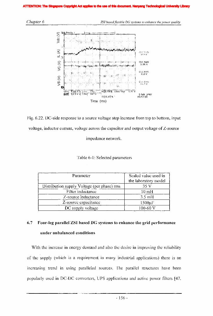
Chapter 6
o'U>
>o>
:;-CI)
>~> •• >
ZSI basedjlexible DG systems to enhance the power quality
elll RIV1S5,38 A
5 Feb 200705:51:56
Time (ms)
Fig. 6.22. DC-side response to a source voltage step increase from top to bottom, input
voltage, inductor current, voltage across the capacitor and output voltage of Z-source
impedance network.
Table 6-1: Selected parameters
Parameter Scaled value used inthe laboratory model
Distribution supply Voltage (per phase) rms 35 V.Filter inductance 10mB
Z-source inductance 3.5mBZ-source capacitance 1500f.!F
DC supply voltage 100-60 V
6.7 Four-leg parallel ZSI based DG systems to enhance the grid performance
under unbalanced conditions
With the increase in energy demand and also the desire in improving the reliability
of the supply (which is a requirement in many industrial applications) there IS an
increasing trend in uSIng paralleled sources. The parallel structures have been
popularly used in DC-DC converters, UPS applications and active power filters [47,
- 156 -
Iiq
Iod
Ioq
I odq
I max
1,Ie, Ici,Ic2IDC
IL_m
I MPP
IpvI scITHD
IzI Zn
lap*lap
Ia,Ip,IoIa *, Ip*,10*
Iah,Iphlin
12n
I;
afJ axis currentafJ axis reference currentafJO axis current componentsafJO axis reference current componentsafJ axis harmonic current componentsNeutral current of inverter 1Neutral current of inverter 2Zero sequence reference current
Average Z-source inductor currentPerturbed Z-source inductor current
Perturbed load currentConstantGain factor of fifth harmonics filterGain factor of seventh harmonics filterGain factor of eleventh harmonics filterDC side controller proportional gain of PI controllerDC side controller integral gain of PI controllerGain of the inverterIntegral gain of PI controller in current controllerGain of the hth resonance filterProportional gain of AC side inner loop controllerProportional gain of PI controller in current controllerProportional gain of zero sequence resonance controllerIntegral gain of the resonance controllerIntegral gain of the zero sequence resonance controllerIntegral gain of the hth resonance controllerProportional gain of AC side PI controllerIntegral gain of the AC side PI controllerMultiplying factor for harmonics eliminationDC side filter inductanceLoad inductanceNeutral inductanceGrid inductanceLeakage inductance of transformer
XVII
ATTENTION: The Singapore Copyright Act applies to the use of this document. Nanyang Technological University Library

Chapter 6 ZSJ basedflexible DC systems to enhance the power quality
97, 99]. In chapter 5, a three-leg parallel ZSI basedDG system is presented which is
able to operate in both grid connected and islanding modes. Its parallel structure gives
enhanced reliability and maintainability. Moving another step-ahead, this section
proposes a four-leg parallel ZSI based DG system to interface renewable generation
into the grid. Having designed a flexible DG system to utilize the excess capacity, the
focus is now given to unbalance operation in grid connected mode. Again the
emphasis is given to use the excess capacity of DG ~ystem to mitigate the unbalance.
The controllers are designed to support the grid during faults and unbalanced
conditions. This is done by controlling the negative and zero sequence currents in the
bus and it would prevent the DG system having into undesirable voltage conditions.
Towards this end, the modulation strategy and controllers for parallel connected four
leg Z-sourced inverters are presented. Higher level controllers are designed to deliver
constant active power and supply reactive power to support the grid in the presence of
unbalances. Each inverter consists of a current controller in the AC-side designed in
the stationary reference frame to produce high quality waveforms. The controller with
combined P+resonance and repetitive controller designed in the first part of this
chapter (section 6.2) is elnployed to achieve good reference tracking and harmonic
rejection. With the expected larger voltage variations in the renewable sources, the
DC-side controllers are designed to boost the voltage while minimizing voltage
stresses on the switches. Steady state and transient performance of the designed
controllers are tested with simulations carried out using Matlab/Simulink and PLECS
tool-boxes. Furthermore, experimental results are obtained with a laboratory built
prototype to show the efficacy of proposed topology and control method.
- 157 -
Iiq
Iod
Ioq
I odq
I max
1,Ie, Ici,Ic2IDC
IL_m
I MPP
IpvI scITHD
IzI Zn
lap*lap
Ia,Ip,IoIa *, Ip*,10*
Iah,Iphlin
12n
I;
afJ axis currentafJ axis reference currentafJO axis current componentsafJO axis reference current componentsafJ axis harmonic current componentsNeutral current of inverter 1Neutral current of inverter 2Zero sequence reference current
Average Z-source inductor currentPerturbed Z-source inductor current
Perturbed load currentConstantGain factor of fifth harmonics filterGain factor of seventh harmonics filterGain factor of eleventh harmonics filterDC side controller proportional gain of PI controllerDC side controller integral gain of PI controllerGain of the inverterIntegral gain of PI controller in current controllerGain of the hth resonance filterProportional gain of AC side inner loop controllerProportional gain of PI controller in current controllerProportional gain of zero sequence resonance controllerIntegral gain of the resonance controllerIntegral gain of the zero sequence resonance controllerIntegral gain of the hth resonance controllerProportional gain of AC side PI controllerIntegral gain of the AC side PI controllerMultiplying factor for harmonics eliminationDC side filter inductanceLoad inductanceNeutral inductanceGrid inductanceLeakage inductance of transformer
XVII
ATTENTION: The Singapore Copyright Act applies to the use of this document. Nanyang Technological University Library
Chapter 6
6.7.1 Topology
ZSI basedflexible DG systems to enhance the power quality
Similar to three-leg parallel ZSIs presented in chapter 5, the main idea of this four
leg parallel structure is also to increase the reliability, maintainability and current
capacity of the system. In addition, this topology can mitigate zero sequence currents
with the modulation of the 4th leg. Fig. 6.23 shows the four-leg parallel inverter
structure proposed for DG interfacing. Therein two four-leg inverters are connected
into a single Z-source impedance network where each inverter arm is connected to a
filter inductor and then to a common shunt filtering capacitor bank. The forth legs of
the inverters are connected to a neutral filter inductor and its other end is connected to
the common neutral point at the load and capacitor bank. The total inverter system is
connected to the grid at PCC. However, paralleled 4th legs would create an additional
current path increasing the high frequency cross link current which is one
disadvantage of this topology. Also, two additional inductors are necessary to connect
the each of the 4th legs used in respective neutral wires to the neutral point. This
requirement is strictly necessary in particularly with the interleaved modulation
techniques. However, with the use of COmlTIOn Z-source impedance network and
common filter capacitors, the component count can be reduced similar to that in the
structure presented in chapter 5. Furthermore, when the inverters are connected to the
grid, larger inductors are preferred to suppress the ripple currents, even though this
could limit the possible controller bandwidth. However, with the use of interleaved
carrier signals in ITIodulating the inverters (this will be described in detail in the 'latter
part of this section) the effective switching frequency can be doubled and hence the
size of the inductors can be reduced [47]. Similar to the method described in chapter 5,
this method also allows the designer to use a relatively smaller inductance than that
would be necessary in connecting a single inverter, while achieving the desired
- 158 -
Iiq
Iod
Ioq
I odq
I max
1,Ie, Ici,Ic2IDC
IL_m
I MPP
IpvI scITHD
IzI Zn
lap*lap
Ia,Ip,IoIa *, Ip*,10*
Iah,Iphlin
12n
I;
afJ axis currentafJ axis reference currentafJO axis current componentsafJO axis reference current componentsafJ axis harmonic current componentsNeutral current of inverter 1Neutral current of inverter 2Zero sequence reference current
Average Z-source inductor currentPerturbed Z-source inductor current
Perturbed load currentConstantGain factor of fifth harmonics filterGain factor of seventh harmonics filterGain factor of eleventh harmonics filterDC side controller proportional gain of PI controllerDC side controller integral gain of PI controllerGain of the inverterIntegral gain of PI controller in current controllerGain of the hth resonance filterProportional gain of AC side inner loop controllerProportional gain of PI controller in current controllerProportional gain of zero sequence resonance controllerIntegral gain of the resonance controllerIntegral gain of the zero sequence resonance controllerIntegral gain of the hth resonance controllerProportional gain of AC side PI controllerIntegral gain of the AC side PI controllerMultiplying factor for harmonics eliminationDC side filter inductanceLoad inductanceNeutral inductanceGrid inductanceLeakage inductance of transformer
XVII
ATTENTION: The Singapore Copyright Act applies to the use of this document. Nanyang Technological University Library

Chapter 6 ZSJ basedjlexible DG systems to enhance the power quality
bandwidth of the controller [47]. Also, the amount of ripple current could further be
reduced by connecting large number of modules in parallel.
9
Fig. 6.23. Four-leg parallel ZSIs
6.7.2 Modulation design
Conventionally, four-leg inverters are modulated using 3-dimensional space vector
modulation methods based on apO coordinates. However, carrier based modulation
techniques have also been used. A carrier based modulation Inethod is proposed for
ZSIs in [51], where the shoot-through intervals are equally spread and are inserted
carefully so that the shoot-through would occur at the switching transition of each leg.
The advantage of this modulation method is that the number of switchings per half
carrier cycle would remain as same as that of the traditional VSI. Moreover, it has
better spectral characteristics [51]. As described in chapter 5, when the parallel
inverters are lTIodulated with interleaved modulation method, all four shoot-through
intervals cannot be inserted as specified in [51], but only two shoot-through intervals
can be inserted within the half switching period. In addition, when the inverter
modules are independently controlled, inserted shoot-through intervals may not
coincide. This could result in over-boost and distortions in the output waveform. To
- 159 -
Iiq
Iod
Ioq
I odq
I max
1,Ie, Ici,Ic2IDC
IL_m
I MPP
IpvI scITHD
IzI Zn
lap*lap
Ia,Ip,IoIa *, Ip*,10*
Iah,Iphlin
12n
I;
afJ axis currentafJ axis reference currentafJO axis current componentsafJO axis reference current componentsafJ axis harmonic current componentsNeutral current of inverter 1Neutral current of inverter 2Zero sequence reference current
Average Z-source inductor currentPerturbed Z-source inductor current
Perturbed load currentConstantGain factor of fifth harmonics filterGain factor of seventh harmonics filterGain factor of eleventh harmonics filterDC side controller proportional gain of PI controllerDC side controller integral gain of PI controllerGain of the inverterIntegral gain of PI controller in current controllerGain of the hth resonance filterProportional gain of AC side inner loop controllerProportional gain of PI controller in current controllerProportional gain of zero sequence resonance controllerIntegral gain of the resonance controllerIntegral gain of the zero sequence resonance controllerIntegral gain of the hth resonance controllerProportional gain of AC side PI controllerIntegral gain of the AC side PI controllerMultiplying factor for harmonics eliminationDC side filter inductanceLoad inductanceNeutral inductanceGrid inductanceLeakage inductance of transformer
XVII
ATTENTION: The Singapore Copyright Act applies to the use of this document. Nanyang Technological University Library

Chapter 6 ZSI basedflexible DG systems to enhance the power quality
avoid such problems, the modulation method is designed based on the simple shoot
through method as proposed in [14], where the shoot-through is inserted only within
the traditional null interval. However, this leads to an increase in switchings per half
carrier cycle. Fig. 6.24 shows modulation and switching diagram and the switching
signals that are derived from a logic circuit implemented outside the dSPACE, where
generated reference signals (a, b, c, nand SH) are compared with the interleaved
triangular signals. Shoot-through signals are generated by comparing the reference
signals with the carrier and then they are integrated to the four-leg PWM signals as
shown in Fig. 6.24. To have the shoot-through state, both switches of an inverter arm
need to be switched on. To keep the modular independence and to prevent the undue
stressing of a particular inverter module both inverters are put into the shoot-through
state simultaneously. However, the shoot-through signals are only inserted in neutral
legs of the inverters. A single signal is used to generate the shoot-through signal for
both inverters and this would ensure correct overlapping of shoot-through signals and
prevent the unwanted boost. Although it would be possible to spread the shoot-through
among all the switches of the inverters, this would require a complex logic circuit.
Moreover, the neutral conductor carries only the unbalanced current that is slnaller
than the normal current carried by the other legs.
- 160 -
Iiq
Iod
Ioq
I odq
I max
1,Ie, Ici,Ic2IDC
IL_m
I MPP
IpvI scITHD
IzI Zn
lap*lap
Ia,Ip,IoIa *, Ip*,10*
Iah,Iphlin
12n
I;
afJ axis currentafJ axis reference currentafJO axis current componentsafJO axis reference current componentsafJ axis harmonic current componentsNeutral current of inverter 1Neutral current of inverter 2Zero sequence reference current
Average Z-source inductor currentPerturbed Z-source inductor current
Perturbed load currentConstantGain factor of fifth harmonics filterGain factor of seventh harmonics filterGain factor of eleventh harmonics filterDC side controller proportional gain of PI controllerDC side controller integral gain of PI controllerGain of the inverterIntegral gain of PI controller in current controllerGain of the hth resonance filterProportional gain of AC side inner loop controllerProportional gain of PI controller in current controllerProportional gain of zero sequence resonance controllerIntegral gain of the resonance controllerIntegral gain of the zero sequence resonance controllerIntegral gain of the hth resonance controllerProportional gain of AC side PI controllerIntegral gain of the AC side PI controllerMultiplying factor for harmonics eliminationDC side filter inductanceLoad inductanceNeutral inductanceGrid inductanceLeakage inductance of transformer
XVII
ATTENTION: The Singapore Copyright Act applies to the use of this document. Nanyang Technological University Library

Chapter 6 ZSJ basedflexible DG systems to enhance the power quality
8H
a
bn
c
I I I, . I ,I I i I I I i I I i I I ,
I. I I: : I II I! I I 'I I I II I
I· I I: : 1 I1 ;.-'l_:,-.-:I_l---..;.I~l_l __'_1.;....1_I--.:..-1~---i
811~ . I I, > I 1 1--'------:..-1
8 14 -----t-T1--:--1 --l.--lI~!----1I....,.~--:--1_---:I~I.L-!--:-1-1-1 -l----,-J
813 =====±;~Ii~!......--,:,---:,----,I-:-l--:-_--:I~I, .:.,...1,---:--'--,--y:~=±===:::=::t~t:::::::L.--';----:'---J-8 16 ',. L. I, ~
8 15 ! 1 ! I I
8 128 17
~~~ ~~-~I::±::I=~=±::=L-+--+,-+:--i : I ,
8 24 ---L.J:=~! ~~~::::::I~!:::;::' ==~I~! ::=,=:;::,=t::l ~=::;:::l--.:.-_----=-SlI~~~:::!:8
23' I: : I I ..
826
! I I
825
---,.--I--r--~~---I
I I I I I-'=:=======t8 22 ~ f--~I----I----;-+--;-------;--+-:--+--+---;----18 27 'I i, I i ,l ~8 28 ~1--1-1+-i--+---il I I i I ~----+i-l-!-ir-l ! i I ;TI
Fig. 6.24. Modulation and switching signals
6.8 Problem formulation and proposed unbalance mitigation algorithm
Unbalanced voltages are very common particularly in distribution systems with
weak grid conditions and with mircogrids operated in islanding mode. This problem
could arise due to Inany reasons, like unbalanced loads, grid faults and unequal line
impedances. Unbalanced loads would give rise to unbalanced currents, and depending
on the line impedances and short-circuit level of the system, it would generate unequal
voltage drops resulting in unbalanced bus voltages. These unbalanced voltages give
rise to negative sequence voltage components affecting the other loads and sources in
the system. For example, due to the presence of negative sequence cOlnponents, the
- 161 -
Iiq
Iod
Ioq
I odq
I max
1,Ie, Ici,Ic2IDC
IL_m
I MPP
IpvI scITHD
IzI Zn
lap*lap
Ia,Ip,IoIa *, Ip*,10*
Iah,Iphlin
12n
I;
afJ axis currentafJ axis reference currentafJO axis current componentsafJO axis reference current componentsafJ axis harmonic current componentsNeutral current of inverter 1Neutral current of inverter 2Zero sequence reference current
Average Z-source inductor currentPerturbed Z-source inductor current
Perturbed load currentConstantGain factor of fifth harmonics filterGain factor of seventh harmonics filterGain factor of eleventh harmonics filterDC side controller proportional gain of PI controllerDC side controller integral gain of PI controllerGain of the inverterIntegral gain of PI controller in current controllerGain of the hth resonance filterProportional gain of AC side inner loop controllerProportional gain of PI controller in current controllerProportional gain of zero sequence resonance controllerIntegral gain of the resonance controllerIntegral gain of the zero sequence resonance controllerIntegral gain of the hth resonance controllerProportional gain of AC side PI controllerIntegral gain of the AC side PI controllerMultiplying factor for harmonics eliminationDC side filter inductanceLoad inductanceNeutral inductanceGrid inductanceLeakage inductance of transformer
XVII
ATTENTION: The Singapore Copyright Act applies to the use of this document. Nanyang Technological University Library

Chapter 6 ZSl basedflexible DG systems to enhance the power quality
loading ability of induction motors can be reduced, rectifier systems would produce
increased harmonics levels and generators would cease operation with the activation of
their protection systems [41]. Therefore, it is very ilnportant to keep the unbalance
level under control. This could be achieved by properly balancing single phase loads.
SVCs and APFs can also be used with special control algorithms to mitigate
unbalanced currents and voltages [25, 41]. Fig. 6.25(a) shows a single line diagram of
such a distributed system where unbalance is originated from unbalanced loads or
faults. A SVC used to mitigate the unbalances is also shown. The mitigation of
unbalance is achieved by providing an additional path for the unbalanced currents.
Thereby, they are prevented from flowing into the remaining areas of the power
system. For example, when unbalanced currents are injected into bus 1 from the
connected loads, the bus voltage VLoad and the current drawn from bus 2 tends to
become unbalanced. This could create unbalances in the voltage Vpcc at bus 2 as well.
However, if the voltages VLoad is forced to be balanced in the bus 1 then the current
drawn from bus 2 will be balanced and it is possible to reduce the effect of unbalance
on other loads and buses.
DG sources
faults
VLoad ltpcc2
Grid
(a)
- 162 -
Iiq
Iod
Ioq
I odq
I max
1,Ie, Ici,Ic2IDC
IL_m
I MPP
IpvI scITHD
IzI Zn
lap*lap
Ia,Ip,IoIa *, Ip*,10*
Iah,Iphlin
12n
I;
afJ axis currentafJ axis reference currentafJO axis current componentsafJO axis reference current componentsafJ axis harmonic current componentsNeutral current of inverter 1Neutral current of inverter 2Zero sequence reference current
Average Z-source inductor currentPerturbed Z-source inductor current
Perturbed load currentConstantGain factor of fifth harmonics filterGain factor of seventh harmonics filterGain factor of eleventh harmonics filterDC side controller proportional gain of PI controllerDC side controller integral gain of PI controllerGain of the inverterIntegral gain of PI controller in current controllerGain of the hth resonance filterProportional gain of AC side inner loop controllerProportional gain of PI controller in current controllerProportional gain of zero sequence resonance controllerIntegral gain of the resonance controllerIntegral gain of the zero sequence resonance controllerIntegral gain of the hth resonance controllerProportional gain of AC side PI controllerIntegral gain of the AC side PI controllerMultiplying factor for harmonics eliminationDC side filter inductanceLoad inductanceNeutral inductanceGrid inductanceLeakage inductance of transformer
XVII
ATTENTION: The Singapore Copyright Act applies to the use of this document. Nanyang Technological University Library

Chapter 6
Z-source parallelinverters
ZSJ basedjlexible DG systems to enhance the power quality
~oad Vpcc
(b)
Fig. 6.25. (a) Single line diagram of a typical distribution system, (b) Case study used
for simulation and experiments with ZSI.
However, with the presence of DG sources connected uSIng inverters tn large
numbers, these could be used to serve the purpose of unbalance mitigation.
Particularly, since the renewable sources may not run on their full capacity all the
time, this unused capacity could be utilized for some ancillary purposes. Usually, grid
connected DG inverters are operated in current control mode, and they deliver
balanced currents into the grid. In this context, the DG system is proposed to operate
in two modes. Firstly, it should continue to operate in normal mode, when operated at
full capacity and secondly, it could act in unbalance mitigation, when operated at
under rated capacity.
Towards this end, a control algorithm is proposed to modify the current references
to mitigate unbalanced voltages. Fig. 6.25(b) shows the single line diagram used in the
proposed algorithm. To mimic the characteristic of an unbalanced bus, the source
voltage is kept unbalanced initially with known unbalance parameters and voltage
measurement of that bus is used to generate the current references for the inverters.
The reference currents are generated to operate in either of the two modes (see Fig.
6.26). In the first mode, the reference currents are generated based on the
instantaneous power theory for four wire systenls [108] and it would deliver balanced
- 163 -
Iiq
Iod
Ioq
I odq
I max
1,Ie, Ici,Ic2IDC
IL_m
I MPP
IpvI scITHD
IzI Zn
lap*lap
Ia,Ip,IoIa *, Ip*,10*
Iah,Iphlin
12n
I;
afJ axis currentafJ axis reference currentafJO axis current componentsafJO axis reference current componentsafJ axis harmonic current componentsNeutral current of inverter 1Neutral current of inverter 2Zero sequence reference current
Average Z-source inductor currentPerturbed Z-source inductor current
Perturbed load currentConstantGain factor of fifth harmonics filterGain factor of seventh harmonics filterGain factor of eleventh harmonics filterDC side controller proportional gain of PI controllerDC side controller integral gain of PI controllerGain of the inverterIntegral gain of PI controller in current controllerGain of the hth resonance filterProportional gain of AC side inner loop controllerProportional gain of PI controller in current controllerProportional gain of zero sequence resonance controllerIntegral gain of the resonance controllerIntegral gain of the zero sequence resonance controllerIntegral gain of the hth resonance controllerProportional gain of AC side PI controllerIntegral gain of the AC side PI controllerMultiplying factor for harmonics eliminationDC side filter inductanceLoad inductanceNeutral inductanceGrid inductanceLeakage inductance of transformer
XVII
ATTENTION: The Singapore Copyright Act applies to the use of this document. Nanyang Technological University Library

Chapter 6 ZSl basedflexible DG systems to enhance the power quality
currents if the system is balanced and further control of zero sequence currents can
also be carried out if necessary. The zero sequence component of grid voltage can be
obtained directly from transforming the measured voltage into af30 reference frame
and positive sequence components of the grid voltages are extracted using the
sequence filter proposed in [110]. In the second mode, additional reference
components are added to previously generated reference signals in order to control the
negative sequence current in the system. The additional signals are generated by
detecting the negative sequence components in the grid voltage from the filter
proposed in [110]. This allows the complete controller design and implementation to
be carried out in the stationary reference frame. The detected negative sequence
voltages are transformed into stationary reference frame and are given a 90° phase shift
to generate the current reference and it is then multiplied with a gain factor based on
the instantaneous system dispatch power and stability limits. Though the inverters may
not be able to fully mitigate the distortion, still it is possible to use the unused capacity
of the DO system to support the grid while keeping the system capacity limits. This
would be really beneficial in weak grid conditions.
p
+Vev
a+
~XfJ Sequence Referencefilter VI; calculator
Vo
V;V,x/i Reference-Ve
Sequence calculator
filter V/~ I;
Fig. 6.26. Reference current generator
- ]64 -
Iiq
Iod
Ioq
I odq
I max
1,Ie, Ici,Ic2IDC
IL_m
I MPP
IpvI scITHD
IzI Zn
lap*lap
Ia,Ip,IoIa *, Ip*,10*
Iah,Iphlin
12n
I;
afJ axis currentafJ axis reference currentafJO axis current componentsafJO axis reference current componentsafJ axis harmonic current componentsNeutral current of inverter 1Neutral current of inverter 2Zero sequence reference current
Average Z-source inductor currentPerturbed Z-source inductor current
Perturbed load currentConstantGain factor of fifth harmonics filterGain factor of seventh harmonics filterGain factor of eleventh harmonics filterDC side controller proportional gain of PI controllerDC side controller integral gain of PI controllerGain of the inverterIntegral gain of PI controller in current controllerGain of the hth resonance filterProportional gain of AC side inner loop controllerProportional gain of PI controller in current controllerProportional gain of zero sequence resonance controllerIntegral gain of the resonance controllerIntegral gain of the zero sequence resonance controllerIntegral gain of the hth resonance controllerProportional gain of AC side PI controllerIntegral gain of the AC side PI controllerMultiplying factor for harmonics eliminationDC side filter inductanceLoad inductanceNeutral inductanceGrid inductanceLeakage inductance of transformer
XVII
ATTENTION: The Singapore Copyright Act applies to the use of this document. Nanyang Technological University Library
Chapter 6 ZSI basedjlexible DG systems to enhance the power quality
6.9 Modeling and controller designing
In chapter 5, controllers for the parallel ZSI is designed with modeling ZSI as a
combination of fast and slow systems and assuming the existence of time scale
decoupling between the two systems. The AC-side controllers are designed in
synchronous reference frame and the DC-side controllers are designed with two loop
configuration. In the present case also it is assumed that the time scale decoupling
holds, and separate controllers are needed for the AC and DC side sub systems. The
system is modeled and the controllers are designed in the stationary reference frame
with a separate controller for each of the upO sequences. The controllers are designed
using a negative. feedback time delay line with an embedded proportional plus
resonance controller.
Fig. 6.27 shows the simplified diagram of the DG system, and illustrates the AC and
DC side subsystems, and different current components present within the DG system.
As indicated in the figure, there can be two types of circulating currents present in this
conyerter. The first current component is similar to the previous parallel topology
where it lies between three phase legs of the two inverters and the second is between
4th legs and inductors connected with the 4th leg. However, it is possible observe that
circulation current in between neutral inductors cannot be detected and controlled by
using the three phase line current measurements. Therefore, it has to be minimized
with the careful selection 4th leg inductors.
- 165 -
Iiq
Iod
Ioq
I odq
I max
1,Ie, Ici,Ic2IDC
IL_m
I MPP
IpvI scITHD
IzI Zn
lap*lap
Ia,Ip,IoIa *, Ip*,10*
Iah,Iphlin
12n
I;
afJ axis currentafJ axis reference currentafJO axis current componentsafJO axis reference current componentsafJ axis harmonic current componentsNeutral current of inverter 1Neutral current of inverter 2Zero sequence reference current
Average Z-source inductor currentPerturbed Z-source inductor current
Perturbed load currentConstantGain factor of fifth harmonics filterGain factor of seventh harmonics filterGain factor of eleventh harmonics filterDC side controller proportional gain of PI controllerDC side controller integral gain of PI controllerGain of the inverterIntegral gain of PI controller in current controllerGain of the hth resonance filterProportional gain of AC side inner loop controllerProportional gain of PI controller in current controllerProportional gain of zero sequence resonance controllerIntegral gain of the resonance controllerIntegral gain of the zero sequence resonance controllerIntegral gain of the hth resonance controllerProportional gain of AC side PI controllerIntegral gain of the AC side PI controllerMultiplying factor for harmonics eliminationDC side filter inductanceLoad inductanceNeutral inductanceGrid inductanceLeakage inductance of transformer
XVII
ATTENTION: The Singapore Copyright Act applies to the use of this document. Nanyang Technological University Library

Chapter 6 ZSI basedflexible DO systems to enhance the power quality
19b
Igc
Before designing the controllers, it is necessary to obtain the mathematical model of
the DG system. As shown in Fig. 6.27, the DG system is silnplified into AC and DC
side sub systems. Modeling of Z-source impedance network has been already dealt in
chapter 4. Therefore, this section now focuses on deriving a model of the AC-side sub
system. Since, both the inverters consist of identical components, modeling of a single
inverter would be adequate. If dx is the average switching duty ratio, then by applying
the KVL to the AC-side of one inverter, for each x phase (x =a, b, c), 6-14 and 6-15
can be obtained. Where p=d/dt, Vs=output voltage of Z-source network, vxm=[Vlam,
Vlbm, Vl cm], the output voltage of inverter, vgx=[vga, Vgb, Vgc], the grid voltage,
vgm=common mode voltage and ilx=[ila, ilb' ilc], output current of the first inverter
and i2x=[i2a, i2b, i2c], output current of the second inverter and igx=[iga, igb' igcl is the grid
current. A similar equation can be obtained for the second inverter.
(6-14)
(6-15)
- 166-
Iiq
Iod
Ioq
I odq
I max
1,Ie, Ici,Ic2IDC
IL_m
I MPP
IpvI scITHD
IzI Zn
lap*lap
Ia,Ip,IoIa *, Ip*,10*
Iah,Iphlin
12n
I;
afJ axis currentafJ axis reference currentafJO axis current componentsafJO axis reference current componentsafJ axis harmonic current componentsNeutral current of inverter 1Neutral current of inverter 2Zero sequence reference current
Average Z-source inductor currentPerturbed Z-source inductor current
Perturbed load currentConstantGain factor of fifth harmonics filterGain factor of seventh harmonics filterGain factor of eleventh harmonics filterDC side controller proportional gain of PI controllerDC side controller integral gain of PI controllerGain of the inverterIntegral gain of PI controller in current controllerGain of the hth resonance filterProportional gain of AC side inner loop controllerProportional gain of PI controller in current controllerProportional gain of zero sequence resonance controllerIntegral gain of the resonance controllerIntegral gain of the zero sequence resonance controllerIntegral gain of the hth resonance controllerProportional gain of AC side PI controllerIntegral gain of the AC side PI controllerMultiplying factor for harmonics eliminationDC side filter inductanceLoad inductanceNeutral inductanceGrid inductanceLeakage inductance of transformer
XVII
ATTENTION: The Singapore Copyright Act applies to the use of this document. Nanyang Technological University Library

Chapter 6 ZSl basedflexible DG systems to enhance the power quality
Unlike in a single inverter system, in a system with parallel inverters modulated
using interleaved carrier signals, a zero sequence current exists between inverter
lTIodules, therefore L ilx=iln+ie and L i2x=i2n-ie, where ie is the circulating current and
iIn and i2n are neutral current of inverter one and two respectively. Common mode
voltage of each module can be written as vgm=VS*(dIa+dlb+dIc)/3. Since the DG
system consists of four wires, PWM modulation signals are in three dimensional
space. All the measured signals are converted to afJO plane by applying the
transformation given in (6-16), and equations 6-17 to 6-23 can be obtained. Where "/'
can be any electrical parameter.
ita + i2a - iga = Cf pvga
(6-16)
(6-17)
(6-18)
(6-19)
(6-20)
(6-21)
(6-22)
(6-23)
Where (vga , Vg~, VgO) , (fal, iPl' ipo) and (iga, igp, igo) are (xfJO axis grid voltage, inverter
output voltage, first inverter output current and grid current respectively. Also diu, d 1f3
- 167 -
Iiq
Iod
Ioq
I odq
I max
1,Ie, Ici,Ic2IDC
IL_m
I MPP
IpvI scITHD
IzI Zn
lap*lap
Ia,Ip,IoIa *, Ip*,10*
Iah,Iphlin
12n
I;
afJ axis currentafJ axis reference currentafJO axis current componentsafJO axis reference current componentsafJ axis harmonic current componentsNeutral current of inverter 1Neutral current of inverter 2Zero sequence reference current
Average Z-source inductor currentPerturbed Z-source inductor current
Perturbed load currentConstantGain factor of fifth harmonics filterGain factor of seventh harmonics filterGain factor of eleventh harmonics filterDC side controller proportional gain of PI controllerDC side controller integral gain of PI controllerGain of the inverterIntegral gain of PI controller in current controllerGain of the hth resonance filterProportional gain of AC side inner loop controllerProportional gain of PI controller in current controllerProportional gain of zero sequence resonance controllerIntegral gain of the resonance controllerIntegral gain of the zero sequence resonance controllerIntegral gain of the hth resonance controllerProportional gain of AC side PI controllerIntegral gain of the AC side PI controllerMultiplying factor for harmonics eliminationDC side filter inductanceLoad inductanceNeutral inductanceGrid inductanceLeakage inductance of transformer
XVII
ATTENTION: The Singapore Copyright Act applies to the use of this document. Nanyang Technological University Library
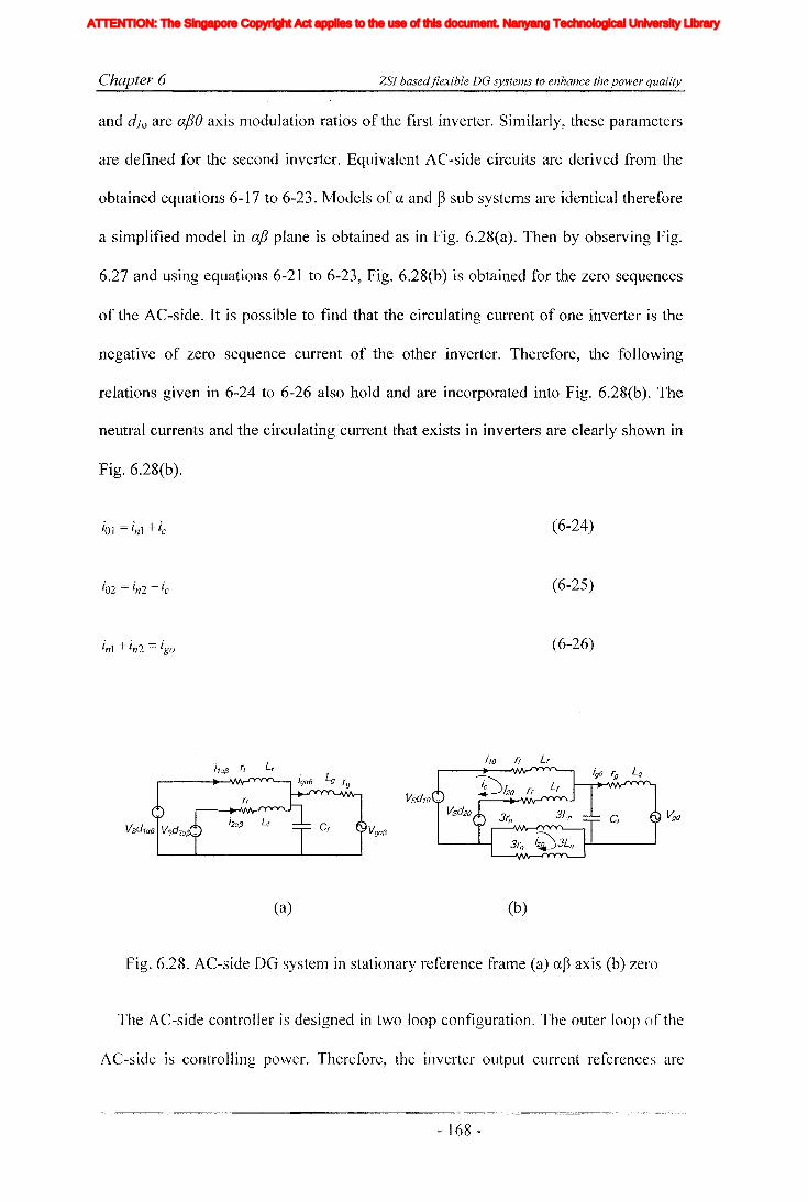
Chapter 6 ZSJ basedflexible DO systems to enhance the power quality
and dlo are afJO axis modulation ratios of the first inverter. Similarly, these parameters
are defined for the second inverter. Equivalent AC-side circuits are derived from the
obtained equations 6-17 to 6-23. Models of a and Bsub systems are identical therefore
a simplified model in a/3 plane is obtained as in Fig. 6.28(a). Then by observing Fig.
6.27 and using equations 6-21 to 6-23, Fig. 6.28(b) is obtained for the zero sequences
of the AC-side. It is possible to find that the circulating current of one inverter is the
negative of zero sequence current of the other inverter. Therefore, the following
relations given in 6-24 to 6-26 also hold and are incorporated into Fig. 6.28(b). The
neutral currents and the circulating current that exists in inverters are clearly shown in
Fig. 6.28(b).
i1a13 (, L,
(a)
ito rf Lf
(b)
(6-24)
(6-25)
(6-26)
vgo
Fig. 6.28. AC-side DG system in stationary reference frame (a) a~ axis (b) zero
The AC-side controller is designed in two loop configuration. The outer loop of the
AC-side is controlling power. Therefore, the inverter output current references are
- 168 -
Iiq
Iod
Ioq
I odq
I max
1,Ie, Ici,Ic2IDC
IL_m
I MPP
IpvI scITHD
IzI Zn
lap*lap
Ia,Ip,IoIa *, Ip*,10*
Iah,Iphlin
12n
I;
afJ axis currentafJ axis reference currentafJO axis current componentsafJO axis reference current componentsafJ axis harmonic current componentsNeutral current of inverter 1Neutral current of inverter 2Zero sequence reference current
Average Z-source inductor currentPerturbed Z-source inductor current
Perturbed load currentConstantGain factor of fifth harmonics filterGain factor of seventh harmonics filterGain factor of eleventh harmonics filterDC side controller proportional gain of PI controllerDC side controller integral gain of PI controllerGain of the inverterIntegral gain of PI controller in current controllerGain of the hth resonance filterProportional gain of AC side inner loop controllerProportional gain of PI controller in current controllerProportional gain of zero sequence resonance controllerIntegral gain of the resonance controllerIntegral gain of the zero sequence resonance controllerIntegral gain of the hth resonance controllerProportional gain of AC side PI controllerIntegral gain of the AC side PI controllerMultiplying factor for harmonics eliminationDC side filter inductanceLoad inductanceNeutral inductanceGrid inductanceLeakage inductance of transformer
XVII
ATTENTION: The Singapore Copyright Act applies to the use of this document. Nanyang Technological University Library

Chapter 6 ZSI basedflexible DG systems to enhance the power quality
calculated uSIng the measured voltage at common coupling point and power
references. Grid connected inverters are expected to deliver high quality power and it
is governed by the current quality. Therefore, the injecting currents should be free
from high frequency as well as low order harmonic components. To suppress
unwanted harmonics, the combined controller designed in section 6.2 is employed.
This combined controller gives effective reference tracking and harmonic elimination
properties. The block diagram representation of the model obtained in ap frame is
presented in Fig. 6.29(a).
From Fig. 6.28(b), the block diagram for the zero sequence sub system is obtained
as shown in Fig. 6.29(b). The controllers are designed to track the neutral current
reference. However, there exist two zero sequence circulation current components as
shown in Fig. 6.28(b). From that, it can be seen that the circulation current flows
between the neutral conductors cannot be controlled by the zero sequence current
controllers as it cannot be derived from measuring only the three phase currents. To
prevent this current, neutral leg inductors with exactly the same size need to be
selected. Then the circulating current that exists between the inverters become the
same in magnitude and opposite in sign and when the neutral currents are controlled to
be as ig,/2=ilO= i20 and the circulating current would reach zero. Therefore, the need of
a separate controller would not arise. Hence, a simplified block diagram is obtained as
given in Fig. 6.29(b) and the combined controller designed in the section 6.2 is
employed to remove possible harmonic current component that could be present in the
neutral current and the circulating current.
- 169 -
Iiq
Iod
Ioq
I odq
I max
1,Ie, Ici,Ic2IDC
IL_m
I MPP
IpvI scITHD
IzI Zn
lap*lap
Ia,Ip,IoIa *, Ip*,10*
Iah,Iphlin
12n
I;
afJ axis currentafJ axis reference currentafJO axis current componentsafJO axis reference current componentsafJ axis harmonic current componentsNeutral current of inverter 1Neutral current of inverter 2Zero sequence reference current
Average Z-source inductor currentPerturbed Z-source inductor current
Perturbed load currentConstantGain factor of fifth harmonics filterGain factor of seventh harmonics filterGain factor of eleventh harmonics filterDC side controller proportional gain of PI controllerDC side controller integral gain of PI controllerGain of the inverterIntegral gain of PI controller in current controllerGain of the hth resonance filterProportional gain of AC side inner loop controllerProportional gain of PI controller in current controllerProportional gain of zero sequence resonance controllerIntegral gain of the resonance controllerIntegral gain of the zero sequence resonance controllerIntegral gain of the hth resonance controllerProportional gain of AC side PI controllerIntegral gain of the AC side PI controllerMultiplying factor for harmonics eliminationDC side filter inductanceLoad inductanceNeutral inductanceGrid inductanceLeakage inductance of transformer
XVII
ATTENTION: The Singapore Copyright Act applies to the use of this document. Nanyang Technological University Library

Chapter 6
l~
ZSI basedflexible DG systems to enhance the power quality
Vga/3 1
Cs
(a)
1
Cs
1--------L------l1o(3Ln +Lf )s+(3rn +~l)
(b)
Fig. 6.29 AC-side controllers (a) a~ controller, (b) zero sequence controller
After designing the AC-side controllers and reference generators, now consider the
DC-side controller. Similar to the model obtained in chapter 5, here also coupling of
zero sequence would disappear when controlled properly. This simplifies the model
and therefore mathematical model obtained in chapter 4 is applicable and is not
repeated here. However, the controller design is different from what is described in the
chapters 4 and 5. The controller design in this systelTI is similar to the one described in
section 6.4.2 where the output voltage of Z-source capacitor is controlled to track a
fixed reference. Therefore, voltage stress on the switches is minimal and inverters
utilize boosted voltage effectively. Furthermore, the cushioning method proposed in
chapter 4 is employed, that would prevent transferring of DC-side disturbance into the
AC-side. Finally, the overall controller is given in Fig. 6.30 where it shows the
COITIlTIOn power, DC-side and AC-side controllers that are previously proposed.
- 170 -
Iiq
Iod
Ioq
I odq
I max
1,Ie, Ici,Ic2IDC
IL_m
I MPP
IpvI scITHD
IzI Zn
lap*lap
Ia,Ip,IoIa *, Ip*,10*
Iah,Iphlin
12n
I;
afJ axis currentafJ axis reference currentafJO axis current componentsafJO axis reference current componentsafJ axis harmonic current componentsNeutral current of inverter 1Neutral current of inverter 2Zero sequence reference current
Average Z-source inductor currentPerturbed Z-source inductor current
Perturbed load currentConstantGain factor of fifth harmonics filterGain factor of seventh harmonics filterGain factor of eleventh harmonics filterDC side controller proportional gain of PI controllerDC side controller integral gain of PI controllerGain of the inverterIntegral gain of PI controller in current controllerGain of the hth resonance filterProportional gain of AC side inner loop controllerProportional gain of PI controller in current controllerProportional gain of zero sequence resonance controllerIntegral gain of the resonance controllerIntegral gain of the zero sequence resonance controllerIntegral gain of the hth resonance controllerProportional gain of AC side PI controllerIntegral gain of the AC side PI controllerMultiplying factor for harmonics eliminationDC side filter inductanceLoad inductanceNeutral inductanceGrid inductanceLeakage inductance of transformer
XVII
ATTENTION: The Singapore Copyright Act applies to the use of this document. Nanyang Technological University Library

Chapter 6 ZSI basedflexible DG systems to enhance the power quality
GridVg 3 ---+---
Fig. 6.30. Designed controller for four-leg parallel ZSI
6.10 Simulations results
Simulations for the proposed DG system are carried out in Matlab/Simulink and
PLECS. The controller is developed in Simulink and the power circuit is developed
using PLECS tool-box. Simulations are carried out to show the dynamics and the
performance of the designed controllers. The designed controllers would deliver
specified active and reactive power with balanced currents when the grid voltages are
balanced. In addition, silTIulation results are obtained to highlight the performance of
the DG system under unbalanced conditions. In the first mode, even when the system
is unbalanced, it would inject necessary power to the grid while lnitigating only the
zero sequence components. Simulation results are shown in Fig. 6.31. Initially, the
system operates in the first mode, at t = 150ms, the systenl is transferred into the
- 171 -
Iiq
Iod
Ioq
I odq
I max
1,Ie, Ici,Ic2IDC
IL_m
I MPP
IpvI scITHD
IzI Zn
lap*lap
Ia,Ip,IoIa *, Ip*,10*
Iah,Iphlin
12n
I;
afJ axis currentafJ axis reference currentafJO axis current componentsafJO axis reference current componentsafJ axis harmonic current componentsNeutral current of inverter 1Neutral current of inverter 2Zero sequence reference current
Average Z-source inductor currentPerturbed Z-source inductor current
Perturbed load currentConstantGain factor of fifth harmonics filterGain factor of seventh harmonics filterGain factor of eleventh harmonics filterDC side controller proportional gain of PI controllerDC side controller integral gain of PI controllerGain of the inverterIntegral gain of PI controller in current controllerGain of the hth resonance filterProportional gain of AC side inner loop controllerProportional gain of PI controller in current controllerProportional gain of zero sequence resonance controllerIntegral gain of the resonance controllerIntegral gain of the zero sequence resonance controllerIntegral gain of the hth resonance controllerProportional gain of AC side PI controllerIntegral gain of the AC side PI controllerMultiplying factor for harmonics eliminationDC side filter inductanceLoad inductanceNeutral inductanceGrid inductanceLeakage inductance of transformer
XVII
ATTENTION: The Singapore Copyright Act applies to the use of this document. Nanyang Technological University Library

Chapter 6 ZSl basedflexible DG systems to enhance the power quality
second mode. Fig. 6.31(a) shows the unbalanced grid voltage and grid currents
generated from instantaneous power theory and controlled neutral current.
In the second mode, the reference currents are generated to control the negative
sequence voltage at the PCC, providing an additional path for negative sequence
currents originated from the other loads in the grid thus improving the grid voltage. At
t=150ms, the system is transferred from the first mode to the second mode. Fig.
6.31 (b) shows the positive and negative sequence components of the injecting current.
It is possible to observe that, after the transition, the sequence components of the
injected current would settle down to their steady state values. The positive sequence
components are the same as their previous steady state values and in addition now the
current contains negative sequence components. The generation of negative sequence
current components would not affect the average active power injected to the grid.
However, a slight oscillatory power component appears in both active and reactive
power flows. Furthermore, the system may not be able to suppress the negative
sequence currents completely. This is due to power and current limitations of the
inverters and the increase in ripple in the Z-source network as shown in Fig. 6.31 (c).
200180- 140 160Time (ms)
120
-- 100>'-' 0C}> -100'-- ---'
>' 100,'-' '
8 0~ -1 OO'--~____..;;;. ~ ---'
__ 20
~ O~-
~ -20 --'-- --J
10,.....-----r-------..,.-----.....-------'\
~ 0z -10 '--__--I-.__---' ....L-__----L__---'
100
(a)
- 172 -
Iiq
Iod
Ioq
I odq
I max
1,Ie, Ici,Ic2IDC
IL_m
I MPP
IpvI scITHD
IzI Zn
lap*lap
Ia,Ip,IoIa *, Ip*,10*
Iah,Iphlin
12n
I;
afJ axis currentafJ axis reference currentafJO axis current componentsafJO axis reference current componentsafJ axis harmonic current componentsNeutral current of inverter 1Neutral current of inverter 2Zero sequence reference current
Average Z-source inductor currentPerturbed Z-source inductor current
Perturbed load currentConstantGain factor of fifth harmonics filterGain factor of seventh harmonics filterGain factor of eleventh harmonics filterDC side controller proportional gain of PI controllerDC side controller integral gain of PI controllerGain of the inverterIntegral gain of PI controller in current controllerGain of the hth resonance filterProportional gain of AC side inner loop controllerProportional gain of PI controller in current controllerProportional gain of zero sequence resonance controllerIntegral gain of the resonance controllerIntegral gain of the zero sequence resonance controllerIntegral gain of the hth resonance controllerProportional gain of AC side PI controllerIntegral gain of the AC side PI controllerMultiplying factor for harmonics eliminationDC side filter inductanceLoad inductanceNeutral inductanceGrid inductanceLeakage inductance of transformer
XVII
ATTENTION: The Singapore Copyright Act applies to the use of this document. Nanyang Technological University Library

Chapter 6 ZSJ basedjlexible DG systems to enhance the power quality
i ~~E ---------- If· -=-:1~ 1~(----[J 1·
~ -10-------------------·
i_1~1 .~
~ -1:t 120 140~oTime (ms)
(b)
:> 200en>
o15,---------------------,
0"'----------------------'
(c)
Fig. 6.31. Operating mode transition from first to second, (a) AC-side response, from
top to bottom, grid voltage, PCC voltage, output current and neutral current, (b) Grid
current sequence cOlnponents and (c) DC-side response, from top to bottom, output
voltage of impedance network, inductor current and capacitor voltage
- ]73 -
Iiq
Iod
Ioq
I odq
I max
1,Ie, Ici,Ic2IDC
IL_m
I MPP
IpvI scITHD
IzI Zn
lap*lap
Ia,Ip,IoIa *, Ip*,10*
Iah,Iphlin
12n
I;
afJ axis currentafJ axis reference currentafJO axis current componentsafJO axis reference current componentsafJ axis harmonic current componentsNeutral current of inverter 1Neutral current of inverter 2Zero sequence reference current
Average Z-source inductor currentPerturbed Z-source inductor current
Perturbed load currentConstantGain factor of fifth harmonics filterGain factor of seventh harmonics filterGain factor of eleventh harmonics filterDC side controller proportional gain of PI controllerDC side controller integral gain of PI controllerGain of the inverterIntegral gain of PI controller in current controllerGain of the hth resonance filterProportional gain of AC side inner loop controllerProportional gain of PI controller in current controllerProportional gain of zero sequence resonance controllerIntegral gain of the resonance controllerIntegral gain of the zero sequence resonance controllerIntegral gain of the hth resonance controllerProportional gain of AC side PI controllerIntegral gain of the AC side PI controllerMultiplying factor for harmonics eliminationDC side filter inductanceLoad inductanceNeutral inductanceGrid inductanceLeakage inductance of transformer
XVII
ATTENTION: The Singapore Copyright Act applies to the use of this document. Nanyang Technological University Library

Chapter 6
6.11 Experimental results
ZSI basedflexible DG systems to enhance the power quality
The prototype of four-leg parallel ZSI is developed in the laboratory to verify the
proposed topology and control method. The prototype is a scaled down model of the
actual system and is shown in Fig. 6.25(b) and parameter values are listed in Table 6.2.
Three phase AC power supply connected to a resistive load bank is used to emulate the
grid. The controllers are developed in dSPACE DS1103 based hardware environment
and necessary voltages and currents are measured using voltage and current sensors
and they are passed to the digital controller through AID converters. The designed
controllers generate six sinusoidal reference voltages and a constant reference in
synthesizing PWM signals and shoot-through signals respectively for the modulation
of ZSIs. The two reference signals needed to modulate the 4th leg of each inverter is
generated using respective three sine wave references. This prevents the need of
additional DIA channels. A modulator board is designed to produce PWM signals and
shoot-through signals where interleaved triangular carrier and reference signals are
compared. Generated shoot-through signals and two PWM signals for the 4th leg are
then fed into a simple logic board, where the 4th leg modulation signals are modified to
generate shoot-through in both inverters. Obtained experimental results for parallel
ZSIs are given in Fig. 6.32(a). It is evident that both inverters carry equal current since
cross link current contains only the high frequency components. The output current of
the whole system has reduced ripple. This indicates the expected performance of
proposed topology and controllers. Fig. 6.32(b) shows the response of the ZSI to a
DC-side input voltage step change where input voltage is changed fro111 100V to 70Y.
However, it is evident that the disturbance in capacitor voltage is minimal. Fig. 6.33
shows the systelll response to a mode transition from normal mode to unbalance
mitigation mode. This scenario is artificially created by prograJllmable AC power
- 174 -
Iiq
Iod
Ioq
I odq
I max
1,Ie, Ici,Ic2IDC
IL_m
I MPP
IpvI scITHD
IzI Zn
lap*lap
Ia,Ip,IoIa *, Ip*,10*
Iah,Iphlin
12n
I;
afJ axis currentafJ axis reference currentafJO axis current componentsafJO axis reference current componentsafJ axis harmonic current componentsNeutral current of inverter 1Neutral current of inverter 2Zero sequence reference current
Average Z-source inductor currentPerturbed Z-source inductor current
Perturbed load currentConstantGain factor of fifth harmonics filterGain factor of seventh harmonics filterGain factor of eleventh harmonics filterDC side controller proportional gain of PI controllerDC side controller integral gain of PI controllerGain of the inverterIntegral gain of PI controller in current controllerGain of the hth resonance filterProportional gain of AC side inner loop controllerProportional gain of PI controller in current controllerProportional gain of zero sequence resonance controllerIntegral gain of the resonance controllerIntegral gain of the zero sequence resonance controllerIntegral gain of the hth resonance controllerProportional gain of AC side PI controllerIntegral gain of the AC side PI controllerMultiplying factor for harmonics eliminationDC side filter inductanceLoad inductanceNeutral inductanceGrid inductanceLeakage inductance of transformer
XVII
ATTENTION: The Singapore Copyright Act applies to the use of this document. Nanyang Technological University Library
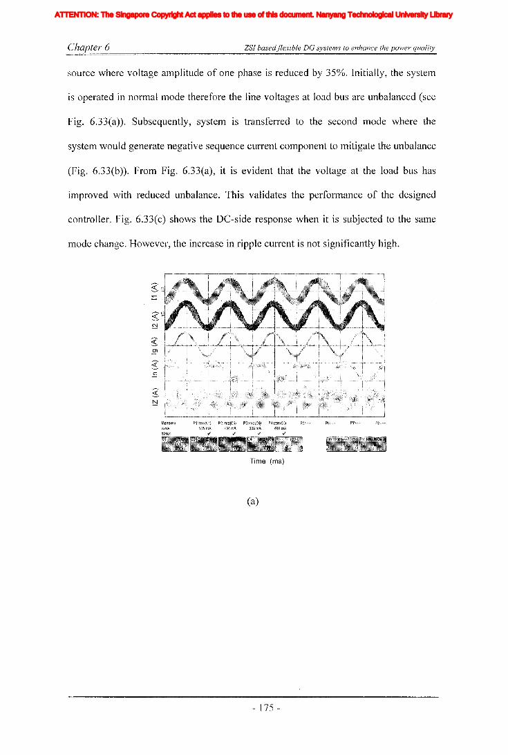
Chapter 6 ZSI basedflexible DG systems to enhance the power quality
source where voltage amplitude of one phase is reduced by 350/0. Initially, the systeln
is operated in normal mode therefore the line voltages at load bus are unbalanced (see
Fig. 6.33(a)). Subsequently, system is transferred to the second mode where the
system would generate negative sequence current component to mitigate the unbalance
(Fig. 6.33(b)). From Fig. 6.33(a), it is evident that the voltage at the load bus has
improved with reduced unbalance. This validates the performance of the designed
controller. Fig. 6.33(c) shows the DC-side response when it is subjected to the same
mode change. However, the increase in ripple current is not significantly high.
Time (ms)
(a)
- 175 -
Iiq
Iod
Ioq
I odq
I max
1,Ie, Ici,Ic2IDC
IL_m
I MPP
IpvI scITHD
IzI Zn
lap*lap
Ia,Ip,IoIa *, Ip*,10*
Iah,Iphlin
12n
I;
afJ axis currentafJ axis reference currentafJO axis current componentsafJO axis reference current componentsafJ axis harmonic current componentsNeutral current of inverter 1Neutral current of inverter 2Zero sequence reference current
Average Z-source inductor currentPerturbed Z-source inductor current
Perturbed load currentConstantGain factor of fifth harmonics filterGain factor of seventh harmonics filterGain factor of eleventh harmonics filterDC side controller proportional gain of PI controllerDC side controller integral gain of PI controllerGain of the inverterIntegral gain of PI controller in current controllerGain of the hth resonance filterProportional gain of AC side inner loop controllerProportional gain of PI controller in current controllerProportional gain of zero sequence resonance controllerIntegral gain of the resonance controllerIntegral gain of the zero sequence resonance controllerIntegral gain of the hth resonance controllerProportional gain of AC side PI controllerIntegral gain of the AC side PI controllerMultiplying factor for harmonics eliminationDC side filter inductanceLoad inductanceNeutral inductanceGrid inductanceLeakage inductance of transformer
XVII
ATTENTION: The Singapore Copyright Act applies to the use of this document. Nanyang Technological University Library

Chapter 6
:;-()
>
~(f)
>
ZSI basedflexible DG systems to enhance the power quality
Time (ms)
(b)
Fig. 6.32. (a)Steady state response of parallel ZSIs, (b) DC-side response ofparallel
inverters for DC input voltage step change voltage across the Z-source capacitor (top),
inductor current and supply voltage to inverter (bottom)
Time (ms)
(a)
- 176 -
Iiq
Iod
Ioq
I odq
I max
1,Ie, Ici,Ic2IDC
IL_m
I MPP
IpvI scITHD
IzI Zn
lap*lap
Ia,Ip,IoIa *, Ip*,10*
Iah,Iphlin
12n
I;
afJ axis currentafJ axis reference currentafJO axis current componentsafJO axis reference current componentsafJ axis harmonic current componentsNeutral current of inverter 1Neutral current of inverter 2Zero sequence reference current
Average Z-source inductor currentPerturbed Z-source inductor current
Perturbed load currentConstantGain factor of fifth harmonics filterGain factor of seventh harmonics filterGain factor of eleventh harmonics filterDC side controller proportional gain of PI controllerDC side controller integral gain of PI controllerGain of the inverterIntegral gain of PI controller in current controllerGain of the hth resonance filterProportional gain of AC side inner loop controllerProportional gain of PI controller in current controllerProportional gain of zero sequence resonance controllerIntegral gain of the resonance controllerIntegral gain of the zero sequence resonance controllerIntegral gain of the hth resonance controllerProportional gain of AC side PI controllerIntegral gain of the AC side PI controllerMultiplying factor for harmonics eliminationDC side filter inductanceLoad inductanceNeutral inductanceGrid inductanceLeakage inductance of transformer
XVII
ATTENTION: The Singapore Copyright Act applies to the use of this document. Nanyang Technological University Library

Chapter 6 ZSI basedflexible DG systems to enhance the power quality
~ '; ,;~,·"·";c"·"·",:;"""·"",,,·,,,,,,,,":;,:,,,,·,,,·,,,,··"·':':'d,," ·".."..·...."" ..··,:g::,·:·":·:·,::.·· ..';:++· ..,·"·,,,, ..·,,"c:
E
Time (ms)
(b)
2o>
2if)
>
Time (ms)
(c)
Fig. 6.33. Response of parallel structure for the operating mode transition from first to
second, (a) Load voltage, (b) output current and neutral current, (c) from top to
bottom, inductor current, voltage across the Z-source capacitor, and supply voltage to
inverter
- 177 -
Iiq
Iod
Ioq
I odq
I max
1,Ie, Ici,Ic2IDC
IL_m
I MPP
IpvI scITHD
IzI Zn
lap*lap
Ia,Ip,IoIa *, Ip*,10*
Iah,Iphlin
12n
I;
afJ axis currentafJ axis reference currentafJO axis current componentsafJO axis reference current componentsafJ axis harmonic current componentsNeutral current of inverter 1Neutral current of inverter 2Zero sequence reference current
Average Z-source inductor currentPerturbed Z-source inductor current
Perturbed load currentConstantGain factor of fifth harmonics filterGain factor of seventh harmonics filterGain factor of eleventh harmonics filterDC side controller proportional gain of PI controllerDC side controller integral gain of PI controllerGain of the inverterIntegral gain of PI controller in current controllerGain of the hth resonance filterProportional gain of AC side inner loop controllerProportional gain of PI controller in current controllerProportional gain of zero sequence resonance controllerIntegral gain of the resonance controllerIntegral gain of the zero sequence resonance controllerIntegral gain of the hth resonance controllerProportional gain of AC side PI controllerIntegral gain of the AC side PI controllerMultiplying factor for harmonics eliminationDC side filter inductanceLoad inductanceNeutral inductanceGrid inductanceLeakage inductance of transformer
XVII
ATTENTION: The Singapore Copyright Act applies to the use of this document. Nanyang Technological University Library
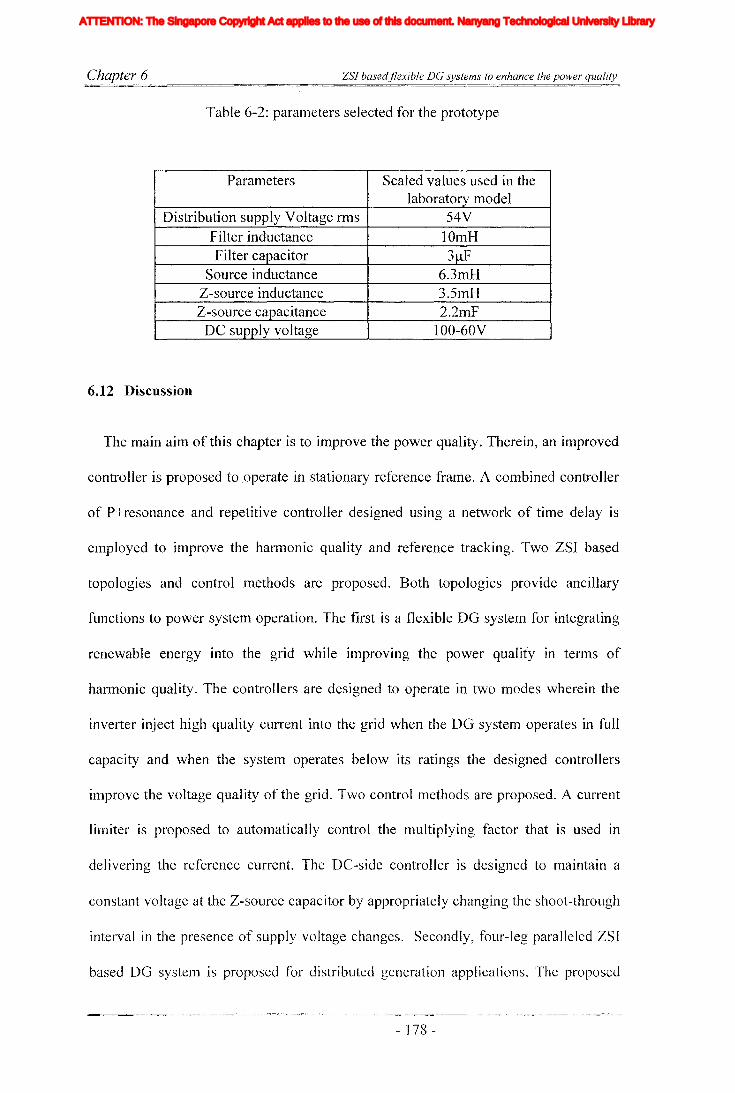
Chapter 6 ZSJ basedflexible DG systems to enhance the power quality
Table 6-2: parameters selected for the prototype
Parameters Scaled values used in thelaboratory model
Distribution supply Voltage fillS 54VFilter inductance lOmHFilter capacitor 3)lF
Source inductance 6.3mHZ-source inductance 3.5mHZ-source capacitance 2.2mF
DC supply voltage IOO-60V
6.12 Discussion
The main aim of this chapter is to improve the power quality. Therein, an improved
controller is proposed to ,operate in stationary reference frame. A combined controller
of P+resonance and repetitive controller designed using a network of time delay is
employed to improve the harmonic quality and reference tracking. Two ZSI based
topologies and control methods are proposed. Both topologies provide ancillary
functions to power system operation. The first is a flexible DO system for integrating
renewable energy into the grid while improving the power quality in terms of
harmonic quality. The controllers are designed to operate in two modes wherein the
inverter inject high quality current into the grid when the DO system operates in full
capacity and when the system operates below its ratings the designed controllers
ilnprove the voltage quality of the grid. Two control Inethods are proposed. A current
limiter is proposed to automatically control the multiplying factor that is used in
delivering the reference current. The DC-side controller is designed to maintain a
constant voltage at the Z-source capacitor by appropriately changing the shoot-through
interval in the presence of supply voltage changes. Secondly, four-leg paralleled ZSI
based DO system is proposed for distributed generation applications. The proposed
- 178 -
Iiq
Iod
Ioq
I odq
I max
1,Ie, Ici,Ic2IDC
IL_m
I MPP
IpvI scITHD
IzI Zn
lap*lap
Ia,Ip,IoIa *, Ip*,10*
Iah,Iphlin
12n
I;
afJ axis currentafJ axis reference currentafJO axis current componentsafJO axis reference current componentsafJ axis harmonic current componentsNeutral current of inverter 1Neutral current of inverter 2Zero sequence reference current
Average Z-source inductor currentPerturbed Z-source inductor current
Perturbed load currentConstantGain factor of fifth harmonics filterGain factor of seventh harmonics filterGain factor of eleventh harmonics filterDC side controller proportional gain of PI controllerDC side controller integral gain of PI controllerGain of the inverterIntegral gain of PI controller in current controllerGain of the hth resonance filterProportional gain of AC side inner loop controllerProportional gain of PI controller in current controllerProportional gain of zero sequence resonance controllerIntegral gain of the resonance controllerIntegral gain of the zero sequence resonance controllerIntegral gain of the hth resonance controllerProportional gain of AC side PI controllerIntegral gain of the AC side PI controllerMultiplying factor for harmonics eliminationDC side filter inductanceLoad inductanceNeutral inductanceGrid inductanceLeakage inductance of transformer
XVII
ATTENTION: The Singapore Copyright Act applies to the use of this document. Nanyang Technological University Library

Chapter 6 ZSI basedflexible DC systems to enhance the power quality
topology designed to deliver balanced active power into the grid in normal conditions
and support the grid in an event of unbalance or fault conditions by controlling the
negative sequence currents. Proposed controller would inject high quality current in
both operating modes. In addition, with the modulation of the inverter fourth leg, zero
sequence currents at the pee is also controlled. In designing the DG system,
modulation method and controller design are carried out to keep the modular
independence of the system intact so that each module could operate independently.
Towards this end, a modulation method is introduced and controllers are designed to
maintain quality waveforms. The topologies and control methods are verified with
simulation results obtained using Matlab/Simulink and PLECS toolboxes. The
laboratory prototypes are built to prove the performance of the designed controller in
producing results in compliance with the theory and simulation results.
- 179 -
Iiq
Iod
Ioq
I odq
I max
1,Ie, Ici,Ic2IDC
IL_m
I MPP
IpvI scITHD
IzI Zn
lap*lap
Ia,Ip,IoIa *, Ip*,10*
Iah,Iphlin
12n
I;
afJ axis currentafJ axis reference currentafJO axis current componentsafJO axis reference current componentsafJ axis harmonic current componentsNeutral current of inverter 1Neutral current of inverter 2Zero sequence reference current
Average Z-source inductor currentPerturbed Z-source inductor current
Perturbed load currentConstantGain factor of fifth harmonics filterGain factor of seventh harmonics filterGain factor of eleventh harmonics filterDC side controller proportional gain of PI controllerDC side controller integral gain of PI controllerGain of the inverterIntegral gain of PI controller in current controllerGain of the hth resonance filterProportional gain of AC side inner loop controllerProportional gain of PI controller in current controllerProportional gain of zero sequence resonance controllerIntegral gain of the resonance controllerIntegral gain of the zero sequence resonance controllerIntegral gain of the hth resonance controllerProportional gain of AC side PI controllerIntegral gain of the AC side PI controllerMultiplying factor for harmonics eliminationDC side filter inductanceLoad inductanceNeutral inductanceGrid inductanceLeakage inductance of transformer
XVII
ATTENTION: The Singapore Copyright Act applies to the use of this document. Nanyang Technological University Library

Chapter 7 Fault ride-through andpower quality improvement with ZSI
Chapter 7
Fault ride-through and power quality improvement
with ZSI
7.1 Introduction
The power distribution networks intermittently face unbalances, faults and
interruptions; these would seriously affect the functionality of the system and leads to
malfunction of loads. In chapter 5, grid connected DG system is studied and
controllers are designed to power the grid and in case of grid fault the DG system is
isolated and operated in islanding mode continuing to power the locally connected
loads. Then in chapter 6, designed DG system would continue to power the grid in
case of a mild unbalance condition and would help to correct the unbalance and zero
sequence conditions. However, DG system has to be isolated from the grid in the case
of large fault conditions. Furthermore, with the penetration of DG sources in larger
quantities, such isolations would jeopardize the stability of the distribution network.
To avoid such disparities, regulatory bodies have imposed grid codes on connection
and ride-through of grid faults. Conversely, sensitive loads require a continuous supply
of voltage despite the faults in the grid. As mentioned above, fault ride-through has
two aspects, fault ride-through of loads and fault ride-through of sources, and there are
lTIany power electronic solutions to solve this ride through problems i.e. DVR, UPQC
and UPS systems [27, 29, 32, 45, 49, 88, 90, 111, 112]. This chapter focuses on both
these aspects of fault ride-through problem and therein two topologies are considered.
- 180-
Iiq
Iod
Ioq
I odq
I max
1,Ie, Ici,Ic2IDC
IL_m
I MPP
IpvI scITHD
IzI Zn
lap*lap
Ia,Ip,IoIa *, Ip*,10*
Iah,Iphlin
12n
I;
afJ axis currentafJ axis reference currentafJO axis current componentsafJO axis reference current componentsafJ axis harmonic current componentsNeutral current of inverter 1Neutral current of inverter 2Zero sequence reference current
Average Z-source inductor currentPerturbed Z-source inductor current
Perturbed load currentConstantGain factor of fifth harmonics filterGain factor of seventh harmonics filterGain factor of eleventh harmonics filterDC side controller proportional gain of PI controllerDC side controller integral gain of PI controllerGain of the inverterIntegral gain of PI controller in current controllerGain of the hth resonance filterProportional gain of AC side inner loop controllerProportional gain of PI controller in current controllerProportional gain of zero sequence resonance controllerIntegral gain of the resonance controllerIntegral gain of the zero sequence resonance controllerIntegral gain of the hth resonance controllerProportional gain of AC side PI controllerIntegral gain of the AC side PI controllerMultiplying factor for harmonics eliminationDC side filter inductanceLoad inductanceNeutral inductanceGrid inductanceLeakage inductance of transformer
XVII
ATTENTION: The Singapore Copyright Act applies to the use of this document. Nanyang Technological University Library
Chapter 7 Fault ride-through andpower quality improvement with ZSl
Mainly faults are in the form of voltage sags and they can cause malfunction of
loads leading to severe process disruptions. Therefore, cost-effective solutions which
can help sensitive loads to ride-through momentary power supply disturbances have
attracted many researchers' attention. Among the recently developed custom power
devices, the DVR is gaining acceptance as an effective device for voltage sag
compensation in distribution systems [1, 27, 32, 111], and it would help to keep the
acceptable voltage level at the load end despite the variations in the utility end. The
DVR consists of an energy source, storage, inverter and transformer. The voltage
compensation ability of the DVR primarily depends on the maximum voltage injection
ability and the amount of stored energy available within the restorer. A new topology
based on ZSI for the DVR is proposed to enhance the voltage restoration property of
the device.
In case of DG based UPS systems, single inverter cannot power the grid while
maintaining the expected voltage at the load. Generally, this is overcome by having a
DG system connected with two inverters, where one inverter is connected in parallel to
the grid and other inverter is connected in series through a transformer. T4e series
inverter would inject the voltage difference in the load bus and the grid. This chapter
also proposes the second topology, a ZSI based power quality compensator and a
control structure that supplies high quality voltage to the connected sensitive load
despite the presence of other non linear loads. The proposed topology consists of
combination of a shunt and a series inverters connected to a common Z-source
impedance network. The shunt inverter is employed with a combined P+resonance
tilne dealy controller designed in the previous chapter and that controls the voltage
quality at the load bus. Whereas, the series inverter enhances the ride-through
capability during grid faults, protects the shunt inverter by limiting the current and also
- 181 -
Iiq
Iod
Ioq
I odq
I max
1,Ie, Ici,Ic2IDC
IL_m
I MPP
IpvI scITHD
IzI Zn
lap*lap
Ia,Ip,IoIa *, Ip*,10*
Iah,Iphlin
12n
I;
afJ axis currentafJ axis reference currentafJO axis current componentsafJO axis reference current componentsafJ axis harmonic current componentsNeutral current of inverter 1Neutral current of inverter 2Zero sequence reference current
Average Z-source inductor currentPerturbed Z-source inductor current
Perturbed load currentConstantGain factor of fifth harmonics filterGain factor of seventh harmonics filterGain factor of eleventh harmonics filterDC side controller proportional gain of PI controllerDC side controller integral gain of PI controllerGain of the inverterIntegral gain of PI controller in current controllerGain of the hth resonance filterProportional gain of AC side inner loop controllerProportional gain of PI controller in current controllerProportional gain of zero sequence resonance controllerIntegral gain of the resonance controllerIntegral gain of the zero sequence resonance controllerIntegral gain of the hth resonance controllerProportional gain of AC side PI controllerIntegral gain of the AC side PI controllerMultiplying factor for harmonics eliminationDC side filter inductanceLoad inductanceNeutral inductanceGrid inductanceLeakage inductance of transformer
XVII
ATTENTION: The Singapore Copyright Act applies to the use of this document. Nanyang Technological University Library

Chapter 7 Fault ride-through and power quality improvement with ZSI
controls the power delivered to the grid. This Z-source based converter provides many
functions to ilnporve the power quality. The performance of the proposed topology
and controller IS validated with simulation results obtained uSIng
Matlab/Simulink/PLECS. Further, it is supported with experimental results obtained
using a prototype built in the laboratory.
7.2 ZSI based DVR system
VSI topology is mainly used in conventional DVR as it gives quality output voltage
with low hannonic levels. The main disadvantage of this topology is its buck type
(step down) output voltage characteristic limiting the maximum voltage that can be
obtained. This means the DVR injection capability would be limited especially when
the DC-link voltage drops below a critical value. As the DVR is required to inject
active power into the distribution line during the period of compensation, the capacity
of the energy storage unit can become a limiting factor in the disturbance
compensation process. Particularly, when capacitors are used as energy storage, the
DC-link voltage will decrease with the dwindling storage energy during compensation.
This could results in poor ride-through of sag if it last for a long period. To overcome
this drawback, an intermediate boost converter stage has been introduced between the
storage device and the DC input terminals of the VSI [113]. However, the introduction
of boost converter would increase number of switches, control loops, protection and
gate-drive circuits. An alternative DVR topology has been proposed thereby the DC
link energy is supplied through a shunt connected converter in [29]. This configuration
requires an additional shunt transfonner and a diode-bridge.
In this section of the chapter, a voltage type ZSI based DVR topology is proposed
where the stored energy in the storage device can be utilized optimally during the
- 182 -
Iiq
Iod
Ioq
I odq
I max
1,Ie, Ici,Ic2IDC
IL_m
I MPP
IpvI scITHD
IzI Zn
lap*lap
Ia,Ip,IoIa *, Ip*,10*
Iah,Iphlin
12n
I;
afJ axis currentafJ axis reference currentafJO axis current componentsafJO axis reference current componentsafJ axis harmonic current componentsNeutral current of inverter 1Neutral current of inverter 2Zero sequence reference current
Average Z-source inductor currentPerturbed Z-source inductor current
Perturbed load currentConstantGain factor of fifth harmonics filterGain factor of seventh harmonics filterGain factor of eleventh harmonics filterDC side controller proportional gain of PI controllerDC side controller integral gain of PI controllerGain of the inverterIntegral gain of PI controller in current controllerGain of the hth resonance filterProportional gain of AC side inner loop controllerProportional gain of PI controller in current controllerProportional gain of zero sequence resonance controllerIntegral gain of the resonance controllerIntegral gain of the zero sequence resonance controllerIntegral gain of the hth resonance controllerProportional gain of AC side PI controllerIntegral gain of the AC side PI controllerMultiplying factor for harmonics eliminationDC side filter inductanceLoad inductanceNeutral inductanceGrid inductanceLeakage inductance of transformer
XVII
ATTENTION: The Singapore Copyright Act applies to the use of this document. Nanyang Technological University Library

Chapter 7 Fault ride-through andpower quality improvement with ZSI
process of voltage compensation with the use of buck-boost property of the ZSI. Even
in DVR topologies using a shunt connected auxiliary supply, the voltage rating of the
shunt transformer, shunt converter and the DC-link capacitor can be kept smaller with
the adoption of ZSI.
The restorer typically consists of an injection transformer, the secondary winding of
which is connected in series with the distribution line, a pulse-width modulated VSI
bridge connected to the primary of the injection transformer and an energy storage
device connected at the DC-link of the inverter bridge [29]. In this context instead of
VSI, ZSI is employed that would provide the unique buck-boost characteristic to the
DVR operation. The output of inverter is filtered in order to mitigate the generated
switching frequency harmonics. A schematic diagram of a proposed ZSI based DVR
incorporated into a distribution network is shown in Fig. 7.1. where Vg=source voltage,
V]=incoming supply voltage before compensation, V2=10ad voltage after
compensation, Vdvr=series injected voltage of the DVR and IFline current. Assume
that the load has an inductance L/, a resistance r/ and the DVR harmonic filter has an
inductance of Lf , a resistance of rf and a capacitance of Cf- The DVR injection
transformer has a combined winding resistance of rt and a leakage inductance ofL t this
parameters values are added to DVR filter in designing the filters and controllers. The
series injected voltage of the DVR, Vdvr, is synthesized by modulating pulse widths of
the inverter-bridge switches. The injection of an appropriate Vdvr in the case of an up
stream voltage disturbance requires a certain amount of real and reactive power supply
from the DVR. It is quite usual for the real power requirement of the DVR be provided
by the energy storage device in the form of a battery, a capacitor bank or a fly-wheel
[113]. And in some DVR topologies, there is a shunt connected auxiliary supply
- 183 -
Iiq
Iod
Ioq
I odq
I max
1,Ie, Ici,Ic2IDC
IL_m
I MPP
IpvI scITHD
IzI Zn
lap*lap
Ia,Ip,IoIa *, Ip*,10*
Iah,Iphlin
12n
I;
afJ axis currentafJ axis reference currentafJO axis current componentsafJO axis reference current componentsafJ axis harmonic current componentsNeutral current of inverter 1Neutral current of inverter 2Zero sequence reference current
Average Z-source inductor currentPerturbed Z-source inductor current
Perturbed load currentConstantGain factor of fifth harmonics filterGain factor of seventh harmonics filterGain factor of eleventh harmonics filterDC side controller proportional gain of PI controllerDC side controller integral gain of PI controllerGain of the inverterIntegral gain of PI controller in current controllerGain of the hth resonance filterProportional gain of AC side inner loop controllerProportional gain of PI controller in current controllerProportional gain of zero sequence resonance controllerIntegral gain of the resonance controllerIntegral gain of the zero sequence resonance controllerIntegral gain of the hth resonance controllerProportional gain of AC side PI controllerIntegral gain of the AC side PI controllerMultiplying factor for harmonics eliminationDC side filter inductanceLoad inductanceNeutral inductanceGrid inductanceLeakage inductance of transformer
XVII
ATTENTION: The Singapore Copyright Act applies to the use of this document. Nanyang Technological University Library
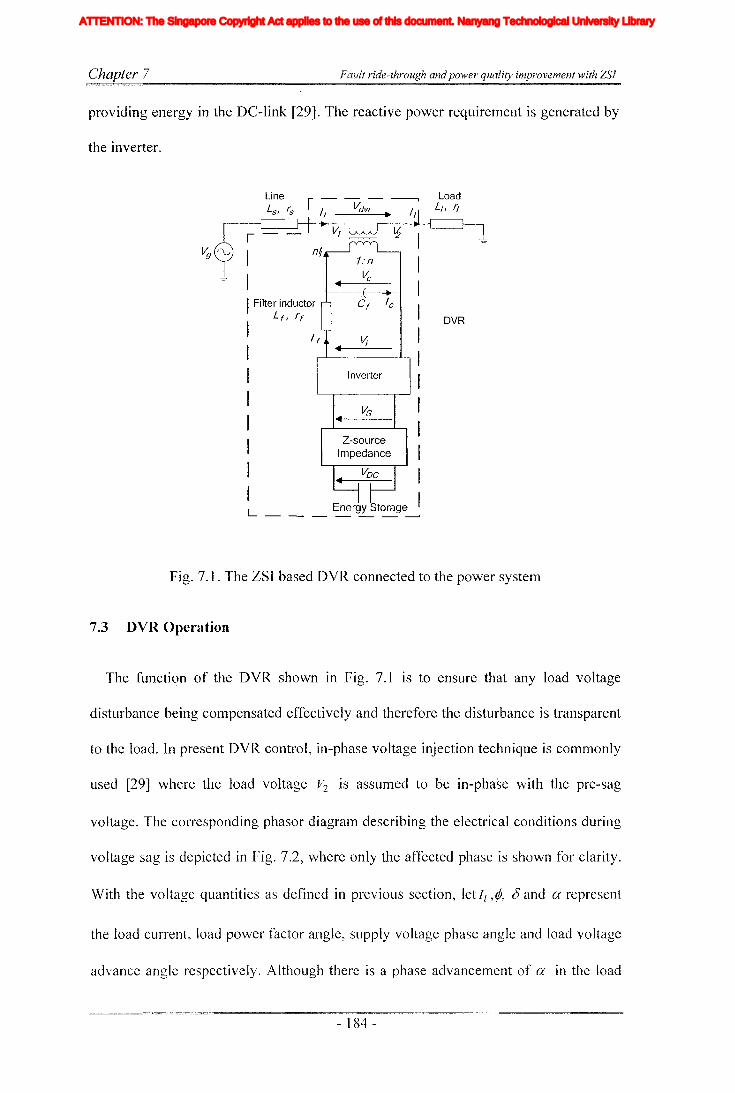
Chapter 7 Fault ride-through and power quality improvement with ZSI
providing energy in the D'C-link [29]. The reactive power requirement is generated by
the inverter.
1:n
• ~
Cf Ie
DVR
11
Inverter
L Energy Storage I------~
Filter inductorL f , rf
Fig. 7.1. The ZSI based DVR connected to the power system
7.3 DVR Operation
The function of the DVR shown in Fig. 7.1 is to ensure that any load voltage
disturbance being compensated effectively and therefore the disturbance is transparent
to the load. In present DVR control, in-phase voltage injection technique is commonly
used [29] where the load voltage v2 is assumed to be in-phase with the pre-sag
voltage. The corresponding phasor diagralTI describing the electrical conditions during
voltage sag is depicted in Fig. 7.2, where only the affected phase is shown for clarity.
With the voltage quantities as defined in previous section, let I, ,rP, () and a represent
the load current, load power factor angle, supply voltage phase angle and load voltage
advance angle respectively. Although there is a phase advancement of a in the load
- 184 -
Iiq
Iod
Ioq
I odq
I max
1,Ie, Ici,Ic2IDC
IL_m
I MPP
IpvI scITHD
IzI Zn
lap*lap
Ia,Ip,IoIa *, Ip*,10*
Iah,Iphlin
12n
I;
afJ axis currentafJ axis reference currentafJO axis current componentsafJO axis reference current componentsafJ axis harmonic current componentsNeutral current of inverter 1Neutral current of inverter 2Zero sequence reference current
Average Z-source inductor currentPerturbed Z-source inductor current
Perturbed load currentConstantGain factor of fifth harmonics filterGain factor of seventh harmonics filterGain factor of eleventh harmonics filterDC side controller proportional gain of PI controllerDC side controller integral gain of PI controllerGain of the inverterIntegral gain of PI controller in current controllerGain of the hth resonance filterProportional gain of AC side inner loop controllerProportional gain of PI controller in current controllerProportional gain of zero sequence resonance controllerIntegral gain of the resonance controllerIntegral gain of the zero sequence resonance controllerIntegral gain of the hth resonance controllerProportional gain of AC side PI controllerIntegral gain of the AC side PI controllerMultiplying factor for harmonics eliminationDC side filter inductanceLoad inductanceNeutral inductanceGrid inductanceLeakage inductance of transformer
XVII
ATTENTION: The Singapore Copyright Act applies to the use of this document. Nanyang Technological University Library
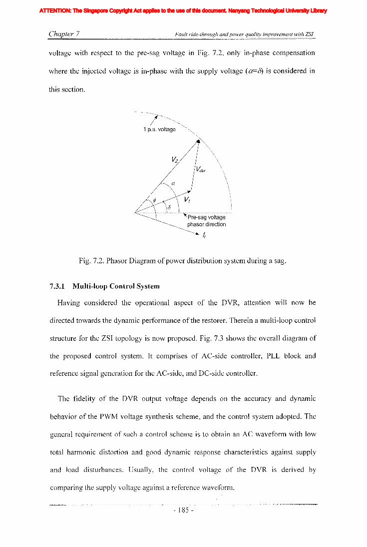
Chapter 7 Fault ride-through and power quality improvement with ZSI
voltage with respect to the pre-sag voltage in Fig. 7.2, only in-phase compensation
where the injected voltage is in-phase with the supply voltage (a=5) is considered in
this section.
a
a \..................................~ :
Pre-sag voltagephasor direction
I;
Fig. 7.2. Phasor Diagram of power distribution system during a sag.
7.3.1 Multi-loop Control System
Having considered the operational aspect of the DVR, attention will now be
directed towards the dynamic performance of the restorer. Therein a lTIulti-loop control
structure for the ZSI topology is now proposed. Fig. 7.3 shows the overall diagram of
the proposed control system. It comprises of AC-side controller, PLL block and
reference signal generation for the AC-side, and DC-side controller.
The fidelity of the DVR output voltage depends on the accuracy and dynamic
behavior of the PWM voltage synthesis scheme, and the control system adopted. The
general requirement of such a control scheme is to obtain an AC waveform with low
total harmonic distoliion and good dynamic response characteristics against supply
and load disturbances. Usually, the control voltage of the DVR is derived by
comparing the supply voltage against a reference waveform.
- ]85 -
Iiq
Iod
Ioq
I odq
I max
1,Ie, Ici,Ic2IDC
IL_m
I MPP
IpvI scITHD
IzI Zn
lap*lap
Ia,Ip,IoIa *, Ip*,10*
Iah,Iphlin
12n
I;
afJ axis currentafJ axis reference currentafJO axis current componentsafJO axis reference current componentsafJ axis harmonic current componentsNeutral current of inverter 1Neutral current of inverter 2Zero sequence reference current
Average Z-source inductor currentPerturbed Z-source inductor current
Perturbed load currentConstantGain factor of fifth harmonics filterGain factor of seventh harmonics filterGain factor of eleventh harmonics filterDC side controller proportional gain of PI controllerDC side controller integral gain of PI controllerGain of the inverterIntegral gain of PI controller in current controllerGain of the hth resonance filterProportional gain of AC side inner loop controllerProportional gain of PI controller in current controllerProportional gain of zero sequence resonance controllerIntegral gain of the resonance controllerIntegral gain of the zero sequence resonance controllerIntegral gain of the hth resonance controllerProportional gain of AC side PI controllerIntegral gain of the AC side PI controllerMultiplying factor for harmonics eliminationDC side filter inductanceLoad inductanceNeutral inductanceGrid inductanceLeakage inductance of transformer
XVII
ATTENTION: The Singapore Copyright Act applies to the use of this document. Nanyang Technological University Library

Chapter 7 Fault ride-through andpower quality improvement with ZSI
Fig. 7.3. Block diagram representation of the ZSI based DVR system with the multi
loop feedback controller.
Purpose of designing closed-loop controllers is to achieve good output voltage
tracking and disturbance rejection. Hence, control variables are changed continuously
with the variations in system inputs and outputs. In the chapter 4 ZSI is modeled and
closed loop controllers are designed for stand-alone type DO systems. Similar
controller strategy is now designed for a DVR system. However, for simplicity in
controller design, the inverter system was considered as two independent units, voltage
source inverter (AC-side) and boost converter (DC-side). The inverter operates as
buck converter by changing the modulation index from the set point, and Z-source
impedance network act as boost converter with large boosting factor.
7.3.2 DC-side controller
When the supply voltage dips for a long tilne, there is a possibility that the terminal
voltage of the storage device would decrease. The proposed controller would be able
- ] 86 -
Iiq
Iod
Ioq
I odq
I max
1,Ie, Ici,Ic2IDC
IL_m
I MPP
IpvI scITHD
IzI Zn
lap*lap
Ia,Ip,IoIa *, Ip*,10*
Iah,Iphlin
12n
I;
afJ axis currentafJ axis reference currentafJO axis current componentsafJO axis reference current componentsafJ axis harmonic current componentsNeutral current of inverter 1Neutral current of inverter 2Zero sequence reference current
Average Z-source inductor currentPerturbed Z-source inductor current
Perturbed load currentConstantGain factor of fifth harmonics filterGain factor of seventh harmonics filterGain factor of eleventh harmonics filterDC side controller proportional gain of PI controllerDC side controller integral gain of PI controllerGain of the inverterIntegral gain of PI controller in current controllerGain of the hth resonance filterProportional gain of AC side inner loop controllerProportional gain of PI controller in current controllerProportional gain of zero sequence resonance controllerIntegral gain of the resonance controllerIntegral gain of the zero sequence resonance controllerIntegral gain of the hth resonance controllerProportional gain of AC side PI controllerIntegral gain of the AC side PI controllerMultiplying factor for harmonics eliminationDC side filter inductanceLoad inductanceNeutral inductanceGrid inductanceLeakage inductance of transformer
XVII
ATTENTION: The Singapore Copyright Act applies to the use of this document. Nanyang Technological University Library
Chapter 7 Fault ride-through andpower quality improvement with ZSI
to generate the desired load voltage even when the VDC goes below VDCLIMIT because of
the boosting action with use of appropriate shoot-through time.
DC-side controller is similar to that of chapter 4; shoot-through time is controlled to
achieve a constant voltage at the output of impedance network. The voltage is
controlled indirectly by measuring the voltage across the capacitor of the impedance
network. A. PI controller is cascaded to remove steady state error as shown in Fig. 7.3.
The inner current loop was closed by cascading a proportional controller to get faster
response. More details of mathematical modeling and controller designing have been
discussed in chapter 4.
7.3.3 AC-side controller and reference signal generation
For the proposed DVR, AC-side controllers are designed in the stationary reference
frame. Usually controllers are designed in the synchronous reference frame. However,
such controllers cannot bring the steady state error to zero (phase and magnitude)
under unbalanced conditions. To compensate unbalanced conditions in synchronous
reference frame, separate positive and negative sequence controllers are required and
this increases required number of axis transformations and. computational time.
Therefore, recently proposed proportional plus resonance controller [29] is adapted in
the stationary reference frame to avoid drawbacks in the synchronous reference frame.
The controller is given in (7-1), where Kp , Kr , and OJo are the proportional gain,
resonance gain and the angular frequency at fundamental frequency. The resonance
controller gives infinite gain at the fundamental frequency that would result in integral
action in that particular frequency while removing the steady state error. Parameters of
the controller are tuned using Naslin polyno1l1ial method as described in reference
[31 ].
- 187 -
Iiq
Iod
Ioq
I odq
I max
1,Ie, Ici,Ic2IDC
IL_m
I MPP
IpvI scITHD
IzI Zn
lap*lap
Ia,Ip,IoIa *, Ip*,10*
Iah,Iphlin
12n
I;
afJ axis currentafJ axis reference currentafJO axis current componentsafJO axis reference current componentsafJ axis harmonic current componentsNeutral current of inverter 1Neutral current of inverter 2Zero sequence reference current
Average Z-source inductor currentPerturbed Z-source inductor current
Perturbed load currentConstantGain factor of fifth harmonics filterGain factor of seventh harmonics filterGain factor of eleventh harmonics filterDC side controller proportional gain of PI controllerDC side controller integral gain of PI controllerGain of the inverterIntegral gain of PI controller in current controllerGain of the hth resonance filterProportional gain of AC side inner loop controllerProportional gain of PI controller in current controllerProportional gain of zero sequence resonance controllerIntegral gain of the resonance controllerIntegral gain of the zero sequence resonance controllerIntegral gain of the hth resonance controllerProportional gain of AC side PI controllerIntegral gain of the AC side PI controllerMultiplying factor for harmonics eliminationDC side filter inductanceLoad inductanceNeutral inductanceGrid inductanceLeakage inductance of transformer
XVII
ATTENTION: The Singapore Copyright Act applies to the use of this document. Nanyang Technological University Library

Chapter 7 Fault ride-through andpower quality improvement with ZSl
(7-1)
Fig. 7.4. Block diagram representation of AC-side controller
By applying KCL and KVL to the AC-side of DVR, mathematical model in abc
domain is obtained. Then it is transformed into the stationary reference frame using
Park's transformation and then obtained equations are used to derive the block
diagram representation as shown in Fig. 7.4. To achieve faster response and stable
output, inner current loop and outer voltage loops are employed in the AC-side
controller. Filter capacitor current is measured and used for inner current loop. It gives
a faster response and stabilizes the output for a current disturbance. A proportional
controller is employed in the inner current loop. Output voltage across the load is
nleasured and it is used to detect the occurrence of sag conditions and to mitigate those
with the use of closed loop controlling. Slower variations are stabilized and good
reference tracking is achieved with the outer voltage loop with employed proportional
plus resonance controller. The measured supply voltage signals are passed through a
PLL. Then reference signals for a and ~ axis are generated using "sine" and "cosine"
signals of the PLL. They are multiplied with a constant value to obtain the correct
magnitude of the reference voltage.
7.4 Simulation and Experimental Verifications
A detailed simulation and experilnental investigations of the DVR system are
- 188 -
Iiq
Iod
Ioq
I odq
I max
1,Ie, Ici,Ic2IDC
IL_m
I MPP
IpvI scITHD
IzI Zn
lap*lap
Ia,Ip,IoIa *, Ip*,10*
Iah,Iphlin
12n
I;
afJ axis currentafJ axis reference currentafJO axis current componentsafJO axis reference current componentsafJ axis harmonic current componentsNeutral current of inverter 1Neutral current of inverter 2Zero sequence reference current
Average Z-source inductor currentPerturbed Z-source inductor current
Perturbed load currentConstantGain factor of fifth harmonics filterGain factor of seventh harmonics filterGain factor of eleventh harmonics filterDC side controller proportional gain of PI controllerDC side controller integral gain of PI controllerGain of the inverterIntegral gain of PI controller in current controllerGain of the hth resonance filterProportional gain of AC side inner loop controllerProportional gain of PI controller in current controllerProportional gain of zero sequence resonance controllerIntegral gain of the resonance controllerIntegral gain of the zero sequence resonance controllerIntegral gain of the hth resonance controllerProportional gain of AC side PI controllerIntegral gain of the AC side PI controllerMultiplying factor for harmonics eliminationDC side filter inductanceLoad inductanceNeutral inductanceGrid inductanceLeakage inductance of transformer
XVII
ATTENTION: The Singapore Copyright Act applies to the use of this document. Nanyang Technological University Library
Chapter 7 Fault ride-through andpower quality improvement with ZSJ
perfonned using Matlab/Simulink and prototype built in the laboratory to verify the
effectiveness of the proposed design. The experimental set-up is designed with a
scaled down model of an actual system and as such simulations are carried out with
the same parameters listed in Table 7-1. The filter inductors and capacitors are
selected to attenuate switching harmonics while avoiding the resonance.
DS 1104
Filter
,,IIIIIII
l---
r----------------------------------------------I PC II II II II II I
I,IIIIIIIIIIIII,
______ J
VDC
Fig. 7.5. Hardware prototype configuration of the DVR.
The hardware configuration of the prototype DVR is shown in Fig. 7.5. A 3-phase
low voltage programmable power source supplies the R-L load through a bank of
series injection transformers. The injection transformer primary windings are
connected to the PWM ZSI via the Le low-pass filter. The inverter consists of six
IGBT switches with anti-paralleled diodes connected across each switch. The DC-link
of the inverter is fed by a separate power supply. The source and load voltages as well·
as the filter capacitor currents are measured by transducers for controlling AC-side.
Inductor current and voltage across the capacitor of Z-source impedance network are
- 189 -
Iiq
Iod
Ioq
I odq
I max
1,Ie, Ici,Ic2IDC
IL_m
I MPP
IpvI scITHD
IzI Zn
lap*lap
Ia,Ip,IoIa *, Ip*,10*
Iah,Iphlin
12n
I;
afJ axis currentafJ axis reference currentafJO axis current componentsafJO axis reference current componentsafJ axis harmonic current componentsNeutral current of inverter 1Neutral current of inverter 2Zero sequence reference current
Average Z-source inductor currentPerturbed Z-source inductor current
Perturbed load currentConstantGain factor of fifth harmonics filterGain factor of seventh harmonics filterGain factor of eleventh harmonics filterDC side controller proportional gain of PI controllerDC side controller integral gain of PI controllerGain of the inverterIntegral gain of PI controller in current controllerGain of the hth resonance filterProportional gain of AC side inner loop controllerProportional gain of PI controller in current controllerProportional gain of zero sequence resonance controllerIntegral gain of the resonance controllerIntegral gain of the zero sequence resonance controllerIntegral gain of the hth resonance controllerProportional gain of AC side PI controllerIntegral gain of the AC side PI controllerMultiplying factor for harmonics eliminationDC side filter inductanceLoad inductanceNeutral inductanceGrid inductanceLeakage inductance of transformer
XVII
ATTENTION: The Singapore Copyright Act applies to the use of this document. Nanyang Technological University Library
Chapter 7 Fault ride-through and power quality improvement with ZSI
measured for DC-side controlling. The measured voltages and currents are interfaced
to dSPACE through AID converters. The closed loop controller is implemented in the
DSP. The measured signals are used to generate the six reference signals which
requires for generating the PWM signals. Generated output signals are interfaced to
external logic board through DIA converters where they are compared with a
triangular carrier to generate PWM signals. The sampling frequency of the control
system is set at 10kHz for the real time controlling. The modulation was done based
on the PWM scheme proposed in [51].
The performance and restoration capability of the DVR is tested by simulation and
experiment subjected to similar sag conditions. The used parameter values are listed in
Table 7-1. When the system is subjected to three phase sag of 40%, the transient
performances at sag front and recovery are observed. Also the performance is
evaluated when the DC voltage drops during long sag. Fig. 7.6 shows the simulated
results of balanced sag. The first plot shows the input supply voltage and sag is
introduced at 40ms. The second plot shows the output of the DVR and it rises fast to
correct the disturbance in the output voltage across the load which is shown in the
third plot. Corresponding experimental results are obtained and plotted as shown in
Fig.7.9, where one phase of the input supply and three phase voltages of the output are
shown. The output voltage shows minimum disturbance despite the presence of a
small notch.
Fig. 7.7 shows the simulated waveforms for sag recovery. The output voltages track
their references although there is a small notch present at the recovery. This results
from the finite sanlpling time used in the controller. Fig. 7.10 shows the corresponding
experiment results and they are complying with sitTIulated results. Fig. 7.8 shows the
- 190 -
Iiq
Iod
Ioq
I odq
I max
1,Ie, Ici,Ic2IDC
IL_m
I MPP
IpvI scITHD
IzI Zn
lap*lap
Ia,Ip,IoIa *, Ip*,10*
Iah,Iphlin
12n
I;
afJ axis currentafJ axis reference currentafJO axis current componentsafJO axis reference current componentsafJ axis harmonic current componentsNeutral current of inverter 1Neutral current of inverter 2Zero sequence reference current
Average Z-source inductor currentPerturbed Z-source inductor current
Perturbed load currentConstantGain factor of fifth harmonics filterGain factor of seventh harmonics filterGain factor of eleventh harmonics filterDC side controller proportional gain of PI controllerDC side controller integral gain of PI controllerGain of the inverterIntegral gain of PI controller in current controllerGain of the hth resonance filterProportional gain of AC side inner loop controllerProportional gain of PI controller in current controllerProportional gain of zero sequence resonance controllerIntegral gain of the resonance controllerIntegral gain of the zero sequence resonance controllerIntegral gain of the hth resonance controllerProportional gain of AC side PI controllerIntegral gain of the AC side PI controllerMultiplying factor for harmonics eliminationDC side filter inductanceLoad inductanceNeutral inductanceGrid inductanceLeakage inductance of transformer
XVII
ATTENTION: The Singapore Copyright Act applies to the use of this document. Nanyang Technological University Library

Chapter 7 Fault ride-through and power quality improvement with ZSI
simulation results when the system is subjected to long sag and corresponding
experimental results are given in Fig. 7.11. During the long sag, a step change of the
DC supply voltage occurs at 40ms where the DC voltage is decreased by 40% to
simulate the discharging effect of the storage element. When this occurs, the DC-side
controllers would adjust the shoot-through time and recovers the load voltage to the set
value. Passing of resulted disturbance into the AC-side was avoided with proper
selection of operating points. This is achieved with adapting the cushioning method
proposed in chapter 4.
Fig. 7.6. Simulated results of the DVR under 40% sag, a=supply voltage, b=output
voltage of the DVR and c=voltage across the load
Table 7-1
Parameters Scaled values used in thelaboratory model
Distribution supply Voltage rms 55 VSeries transformer turns ratio 1:1
Filter capacitance 17~F
Filter inductance 2mHTransfonner series impedance 2.0
Z-source inductance 5mHZ-source capacitance 600~F
DC supply voltage 100-60 V
- 191 -
Iiq
Iod
Ioq
I odq
I max
1,Ie, Ici,Ic2IDC
IL_m
I MPP
IpvI scITHD
IzI Zn
lap*lap
Ia,Ip,IoIa *, Ip*,10*
Iah,Iphlin
12n
I;
afJ axis currentafJ axis reference currentafJO axis current componentsafJO axis reference current componentsafJ axis harmonic current componentsNeutral current of inverter 1Neutral current of inverter 2Zero sequence reference current
Average Z-source inductor currentPerturbed Z-source inductor current
Perturbed load currentConstantGain factor of fifth harmonics filterGain factor of seventh harmonics filterGain factor of eleventh harmonics filterDC side controller proportional gain of PI controllerDC side controller integral gain of PI controllerGain of the inverterIntegral gain of PI controller in current controllerGain of the hth resonance filterProportional gain of AC side inner loop controllerProportional gain of PI controller in current controllerProportional gain of zero sequence resonance controllerIntegral gain of the resonance controllerIntegral gain of the zero sequence resonance controllerIntegral gain of the hth resonance controllerProportional gain of AC side PI controllerIntegral gain of the AC side PI controllerMultiplying factor for harmonics eliminationDC side filter inductanceLoad inductanceNeutral inductanceGrid inductanceLeakage inductance of transformer
XVII
ATTENTION: The Singapore Copyright Act applies to the use of this document. Nanyang Technological University Library

Chapter 7 Fault ride-through andpower quality improvement with ZSI
100
100
80
8060
60
4020100,.-------,------,--------.---r----,
a
b 0
Fig. 7.7. Simulated results of the DVR at recovery from 400/0 sag, a=supply voltage,
b=output voltage of the DVR and c=voltage across the load
Fig. 7.8. Simulated results for a step change in the input DC voltage (40% drop),
a=DC input voltage, b= output voltage of the DVR, c=AC supply voltage, d=output
voltage across load
- 192 -
Iiq
Iod
Ioq
I odq
I max
1,Ie, Ici,Ic2IDC
IL_m
I MPP
IpvI scITHD
IzI Zn
lap*lap
Ia,Ip,IoIa *, Ip*,10*
Iah,Iphlin
12n
I;
afJ axis currentafJ axis reference currentafJO axis current componentsafJO axis reference current componentsafJ axis harmonic current componentsNeutral current of inverter 1Neutral current of inverter 2Zero sequence reference current
Average Z-source inductor currentPerturbed Z-source inductor current
Perturbed load currentConstantGain factor of fifth harmonics filterGain factor of seventh harmonics filterGain factor of eleventh harmonics filterDC side controller proportional gain of PI controllerDC side controller integral gain of PI controllerGain of the inverterIntegral gain of PI controller in current controllerGain of the hth resonance filterProportional gain of AC side inner loop controllerProportional gain of PI controller in current controllerProportional gain of zero sequence resonance controllerIntegral gain of the resonance controllerIntegral gain of the zero sequence resonance controllerIntegral gain of the hth resonance controllerProportional gain of AC side PI controllerIntegral gain of the AC side PI controllerMultiplying factor for harmonics eliminationDC side filter inductanceLoad inductanceNeutral inductanceGrid inductanceLeakage inductance of transformer
XVII
ATTENTION: The Singapore Copyright Act applies to the use of this document. Nanyang Technological University Library

Chapter 7 Fault ride-through andpower quality improvement with ZSJ
200..-----r----~---...------...---~
-200'-----..L----'------"-----1----Io 20 40 60 80 100
200..-----r----~---...-----r------.
b o·
-200'-----..L----'------"-----1----Io 20 40 60 80 100
Time/(ms)
Fig. 7.9. Experimental results of the DVR subjected to a 40% sag, a==supply voltage
and b==voltage across the load
a 20:
-200o 20 40 60 80 100
200,..-----yo-----,----...---.....,----'l
-20000......-----&.20---4.......0---6.......0---8'--0----'100
Time/(ms)
Fig. 7.10. Experimental results of the DVR subjected at recovery from 40% sag,
a=supply voltage and b=voltage across the load
- 193 -
Iiq
Iod
Ioq
I odq
I max
1,Ie, Ici,Ic2IDC
IL_m
I MPP
IpvI scITHD
IzI Zn
lap*lap
Ia,Ip,IoIa *, Ip*,10*
Iah,Iphlin
12n
I;
afJ axis currentafJ axis reference currentafJO axis current componentsafJO axis reference current componentsafJ axis harmonic current componentsNeutral current of inverter 1Neutral current of inverter 2Zero sequence reference current
Average Z-source inductor currentPerturbed Z-source inductor current
Perturbed load currentConstantGain factor of fifth harmonics filterGain factor of seventh harmonics filterGain factor of eleventh harmonics filterDC side controller proportional gain of PI controllerDC side controller integral gain of PI controllerGain of the inverterIntegral gain of PI controller in current controllerGain of the hth resonance filterProportional gain of AC side inner loop controllerProportional gain of PI controller in current controllerProportional gain of zero sequence resonance controllerIntegral gain of the resonance controllerIntegral gain of the zero sequence resonance controllerIntegral gain of the hth resonance controllerProportional gain of AC side PI controllerIntegral gain of the AC side PI controllerMultiplying factor for harmonics eliminationDC side filter inductanceLoad inductanceNeutral inductanceGrid inductanceLeakage inductance of transformer
XVII
ATTENTION: The Singapore Copyright Act applies to the use of this document. Nanyang Technological University Library

Chapter 7 Fault ride-through andpower quality improvement with ZSI
a ~~t=:;u ~h:'" ,n,_:, "do 20 40 60 80 100
b l~
-100~o W W W W 100
clO:~~7\l-100~o W ~ W W 100
d 20:
-200~o 20 40 60 80 100Time/(ms)
Fig. 7.11. Experimental results for step change in the input DC voltage (40% drop),
a==DC input voltage, b=output voltage of DVR, c=AC supply voltage and d=output
voltage across load
7.5 ZSI based power quality compensator with enhanced ride-through
capability
In many industries, UPS systems are commonly used for supplying power to
sensitive loads. There are many types of UPS topologies commonly being employed.
Also, there has been a recent trend in using DG systems to replace UPS schemes [32,
92]. With the deregulation and the implementation of price discrimination strategies, it
would be beneficial to have dedicated generation units to maintain uninterrupted
supply while delivering the excess power to the grid. However, the modern grid
connection standards like IEEE 929 and IEEE 1547 impose strict power quality
requirements (particularly in fault ride-through capability and harmonics quality) when
new DO sources are connected to the grid. Moreover, single inverter DO systems are
- 194 -
Iiq
Iod
Ioq
I odq
I max
1,Ie, Ici,Ic2IDC
IL_m
I MPP
IpvI scITHD
IzI Zn
lap*lap
Ia,Ip,IoIa *, Ip*,10*
Iah,Iphlin
12n
I;
afJ axis currentafJ axis reference currentafJO axis current componentsafJO axis reference current componentsafJ axis harmonic current componentsNeutral current of inverter 1Neutral current of inverter 2Zero sequence reference current
Average Z-source inductor currentPerturbed Z-source inductor current
Perturbed load currentConstantGain factor of fifth harmonics filterGain factor of seventh harmonics filterGain factor of eleventh harmonics filterDC side controller proportional gain of PI controllerDC side controller integral gain of PI controllerGain of the inverterIntegral gain of PI controller in current controllerGain of the hth resonance filterProportional gain of AC side inner loop controllerProportional gain of PI controller in current controllerProportional gain of zero sequence resonance controllerIntegral gain of the resonance controllerIntegral gain of the zero sequence resonance controllerIntegral gain of the hth resonance controllerProportional gain of AC side PI controllerIntegral gain of the AC side PI controllerMultiplying factor for harmonics eliminationDC side filter inductanceLoad inductanceNeutral inductanceGrid inductanceLeakage inductance of transformer
XVII
ATTENTION: The Singapore Copyright Act applies to the use of this document. Nanyang Technological University Library
Chapter 7 Fault ride-through andpower quality improvement with ZSI
not able to function reliably during large grid faults. Therefore, a series and parallel
inverter combination can be employed. This type of topology is common in UPQC and
micro grid controller applications [1, 45, 111]. In the application of micro grids, the
function of the shunt inverter is to supply quality voltage to locally connected sensitive
load and the series inverter is used to enhance the ride-through capability for grid
faults. Both current and voltage control techniques are used to control the series and
the shunt inverters. For example, the shunt inverter is operated in current controlling
,mode and the series inverter operated as a DVR similar to that presented in first part of
this chapter. However, in this case, the series inverter controls the voltage at the
sensitive load and if there is excess power in the DG it will be delivered to the grid or
power would be drawn from the grid to supply the increased load demand if necessary.
In contrast, the method proposed in [1], the shunt inverter is operated using a power
controller with conventional droop techniques and the series inverter would control the
grid current. The main function of this controller is to mitigate the negative sequence
current. Furthermore, two current limiting algorithms are proposed to protect the shunt
inverter in the case of a large grid disturbance [111].
This section of the chapter proposes a different topology and a controlling method.
The new topology is also based on the ZSI [14], where two inverters are connected to
the common Z-source impedance network in the form of series and shunt and this
would minimize the component count. The shunt inverter operates in synchronism
with the grid, reliably supplying voltage to the sensitive load connected at the local
bus. Combined P+resonance and time delay controller designed in chapter 6 is now
employed to improve the voltage quality. The power delivered to the grid is controlled
by the series inverter, which also protects the system froIn grid faults. Unlike the
- 195 -
Iiq
Iod
Ioq
I odq
I max
1,Ie, Ici,Ic2IDC
IL_m
I MPP
IpvI scITHD
IzI Zn
lap*lap
Ia,Ip,IoIa *, Ip*,10*
Iah,Iphlin
12n
I;
afJ axis currentafJ axis reference currentafJO axis current componentsafJO axis reference current componentsafJ axis harmonic current componentsNeutral current of inverter 1Neutral current of inverter 2Zero sequence reference current
Average Z-source inductor currentPerturbed Z-source inductor current
Perturbed load currentConstantGain factor of fifth harmonics filterGain factor of seventh harmonics filterGain factor of eleventh harmonics filterDC side controller proportional gain of PI controllerDC side controller integral gain of PI controllerGain of the inverterIntegral gain of PI controller in current controllerGain of the hth resonance filterProportional gain of AC side inner loop controllerProportional gain of PI controller in current controllerProportional gain of zero sequence resonance controllerIntegral gain of the resonance controllerIntegral gain of the zero sequence resonance controllerIntegral gain of the hth resonance controllerProportional gain of AC side PI controllerIntegral gain of the AC side PI controllerMultiplying factor for harmonics eliminationDC side filter inductanceLoad inductanceNeutral inductanceGrid inductanceLeakage inductance of transformer
XVII
ATTENTION: The Singapore Copyright Act applies to the use of this document. Nanyang Technological University Library
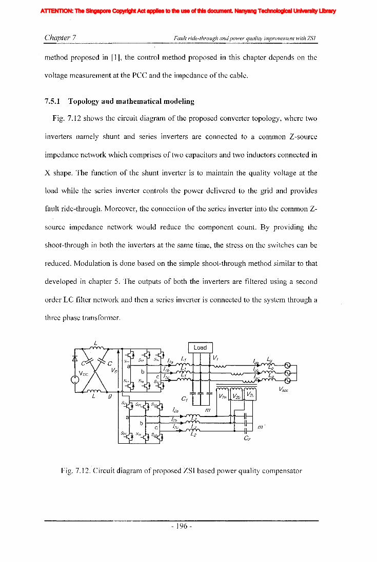
Chapter 7 Fault ride-through and power quality improvement with ZSI
method proposed in [1], the control method proposed in this chapter depends on the
voltage measurement at the pee and the impedance of the cable.
7.5.1 Topology and mathematical modeling
Fig. 7.12 shows the circuit diagram of the proposed converter topology, where two
inverters nan1ely shunt and series inverters are connected to a common Z-source
impedance network which comprises of two capacitors and two inductors connected in
X shape. The function of the shunt inverter is to maintain the quality voltage at the
load while the series inverter controls the power delivered to the grid and provides
fault ride-through. Moreover, the connection of the series inverter into the common Z
source impedance network would reduce the component count. By providing the
shoot-through in both the inverters at the same time, the stress on the switches can be
reduced. Modulation is done based on the simple shoot-through method similar to that
developed in chapter 5. The outputs of both the inverters are filtered using a second
order LC filter network and then a series inverter is connected to the system through a
three phase transformer.
Fig. 7.12. Circuit diagram of proposed ZSI based power quality compensator
- 196 -
Iiq
Iod
Ioq
I odq
I max
1,Ie, Ici,Ic2IDC
IL_m
I MPP
IpvI scITHD
IzI Zn
lap*lap
Ia,Ip,IoIa *, Ip*,10*
Iah,Iphlin
12n
I;
afJ axis currentafJ axis reference currentafJO axis current componentsafJO axis reference current componentsafJ axis harmonic current componentsNeutral current of inverter 1Neutral current of inverter 2Zero sequence reference current
Average Z-source inductor currentPerturbed Z-source inductor current
Perturbed load currentConstantGain factor of fifth harmonics filterGain factor of seventh harmonics filterGain factor of eleventh harmonics filterDC side controller proportional gain of PI controllerDC side controller integral gain of PI controllerGain of the inverterIntegral gain of PI controller in current controllerGain of the hth resonance filterProportional gain of AC side inner loop controllerProportional gain of PI controller in current controllerProportional gain of zero sequence resonance controllerIntegral gain of the resonance controllerIntegral gain of the zero sequence resonance controllerIntegral gain of the hth resonance controllerProportional gain of AC side PI controllerIntegral gain of the AC side PI controllerMultiplying factor for harmonics eliminationDC side filter inductanceLoad inductanceNeutral inductanceGrid inductanceLeakage inductance of transformer
XVII
ATTENTION: The Singapore Copyright Act applies to the use of this document. Nanyang Technological University Library

Chapter 7 Fault ride-through andpower quality improvement with ZSJ
Before designing the controllers, it is necessary to obtain the mathematical model of
the system. Z-source impedance network has already been modeled and closed loop
controllers have been proposed in previous chapters. Therefore, the details of the
mathematical model are not presented here. However, the presented system consists of
a single Z-source ilnpedance network and two inverters bridges in the AC-side. First
consider the AC-side of the shunt inverter shown in Fig. 7.12. By applying KVL to
each phase of the AC-side of the inverter, (7-2) is obtained. Where p=d/dt~ Vlxm= the
local load voltage, Vlgx=output voltage of inverter, Vlgm==common mode voltage, ilx ==
output current of the shunt inverter and x =a, b, c. Similarly, by applying KCL, (7-3)
is obtained. Where iL and, igx are load and grid currents respectively. For the series
inverter it is possible to obtain the state equations given in (7-4)-(7-6), where V2xm' ==
voltage across filter capacitor, V2gx = output voltage of series inverter, vpx== terminal
voltage of connecting cable, i2x == output current. To obtain the stationary reference
frame model, all the state variables are transformed into stationary reference frame
using the transformation matrix given in (7-7). Then it is used to obtain the block
diagram representation of two inverter system and to design controllers, of which
details are presented in the next section.
(7-2)
(7-3)
(7-4)
(7-5)
(7-6)
- 197 -
Iiq
Iod
Ioq
I odq
I max
1,Ie, Ici,Ic2IDC
IL_m
I MPP
IpvI scITHD
IzI Zn
lap*lap
Ia,Ip,IoIa *, Ip*,10*
Iah,Iphlin
12n
I;
afJ axis currentafJ axis reference currentafJO axis current componentsafJO axis reference current componentsafJ axis harmonic current componentsNeutral current of inverter 1Neutral current of inverter 2Zero sequence reference current
Average Z-source inductor currentPerturbed Z-source inductor current
Perturbed load currentConstantGain factor of fifth harmonics filterGain factor of seventh harmonics filterGain factor of eleventh harmonics filterDC side controller proportional gain of PI controllerDC side controller integral gain of PI controllerGain of the inverterIntegral gain of PI controller in current controllerGain of the hth resonance filterProportional gain of AC side inner loop controllerProportional gain of PI controller in current controllerProportional gain of zero sequence resonance controllerIntegral gain of the resonance controllerIntegral gain of the zero sequence resonance controllerIntegral gain of the hth resonance controllerProportional gain of AC side PI controllerIntegral gain of the AC side PI controllerMultiplying factor for harmonics eliminationDC side filter inductanceLoad inductanceNeutral inductanceGrid inductanceLeakage inductance of transformer
XVII
ATTENTION: The Singapore Copyright Act applies to the use of this document. Nanyang Technological University Library

Chapter 7
7.6 Controller design
Fault ride-through andpower quality improvement with ZSJ
(7-7)
ReferenceGenerator
~cc
Fig. 7.13. Block diagram representation of the overall controller
Similar to the previous chapters, the proposed controller is designed based on the
assumption that the dynamics of AC and DC sides of ZSI are significantly different,
hence, time scale decoupling between them can be applied. In this section, the
controller design for the AC and DC side subsystems are considered separately. Fig.
7.13 shows the block diagralTI representation of the overall control system for the
proposed controller that consists of AC and DC side controllers and reference
generators for the proposed topology. Designed DC-side controller is similar to that of
chapter 6 where output voltage of the capacitor is directly controlled. This method
- 198 -
Iiq
Iod
Ioq
I odq
I max
1,Ie, Ici,Ic2IDC
IL_m
I MPP
IpvI scITHD
IzI Zn
lap*lap
Ia,Ip,IoIa *, Ip*,10*
Iah,Iphlin
12n
I;
afJ axis currentafJ axis reference currentafJO axis current componentsafJO axis reference current componentsafJ axis harmonic current componentsNeutral current of inverter 1Neutral current of inverter 2Zero sequence reference current
Average Z-source inductor currentPerturbed Z-source inductor current
Perturbed load currentConstantGain factor of fifth harmonics filterGain factor of seventh harmonics filterGain factor of eleventh harmonics filterDC side controller proportional gain of PI controllerDC side controller integral gain of PI controllerGain of the inverterIntegral gain of PI controller in current controllerGain of the hth resonance filterProportional gain of AC side inner loop controllerProportional gain of PI controller in current controllerProportional gain of zero sequence resonance controllerIntegral gain of the resonance controllerIntegral gain of the zero sequence resonance controllerIntegral gain of the hth resonance controllerProportional gain of AC side PI controllerIntegral gain of the AC side PI controllerMultiplying factor for harmonics eliminationDC side filter inductanceLoad inductanceNeutral inductanceGrid inductanceLeakage inductance of transformer
XVII
ATTENTION: The Singapore Copyright Act applies to the use of this document. Nanyang Technological University Library

Chapter 7 Fault ride-through andpower quality improvement with ZSI
allows better utilization of the boosted voltage and also it reduces voltage stress
applied on the switches. The designed controller comprises of inner current and outer
voltage loops to overcome the inherited non-minimum phase characteristics [59]. The
inner current loop is controlled with a proportional controller whereas a PI controller is
employed in the outer voltage loop to renl0ve the steady state error.
7.6.1 Controlling of the shunt inverter
In industrial and domestic systems, penetration of non-linear loads has increased
due to the increased use of electronically controlled devices leading to an increase in
harmonic levels at load buses. Such harmonic distortions need to be compensated as
the utility would not accept high level of harmonic currents injected into the grid.
Therefore, generated harmonics need to be compensated within the system. In large
industrial systems, special purpose harmonic filters are employed to compensate the
harmonic currents. There are different harmonic controlling techniques proposed in the
literature [103, 109]. Alternatively, the shunt inverter can be used as an active filter to
compensate harmonics if it has sufficient capacity. This is achieved by integrating
harmonic compensating controllers into the main controller. The shunt inverter would
then operate as an interface for the DO source and as an APF to generate harmonics.
As described earlier, the function of the shunt inverter is to supply a steady voltage
to the locally connected sensitive load. Therefore, it is necessary to operate in the
voltage controlling mode. From the mathematical model obtained in the Section 7.5.1,
the block diagram representation of the AC-side of the shunt inverter is obtained and
designed control loops are incorporated as shown in Fig. 7.14. Two controlling loops,
inner current and outer voltage loops are employed to achieve faster response. Both
the controllers are designed in the stationary reference [raBle. This gives the added
- ]99 -
Iiq
Iod
Ioq
I odq
I max
1,Ie, Ici,Ic2IDC
IL_m
I MPP
IpvI scITHD
IzI Zn
lap*lap
Ia,Ip,IoIa *, Ip*,10*
Iah,Iphlin
12n
I;
afJ axis currentafJ axis reference currentafJO axis current componentsafJO axis reference current componentsafJ axis harmonic current componentsNeutral current of inverter 1Neutral current of inverter 2Zero sequence reference current
Average Z-source inductor currentPerturbed Z-source inductor current
Perturbed load currentConstantGain factor of fifth harmonics filterGain factor of seventh harmonics filterGain factor of eleventh harmonics filterDC side controller proportional gain of PI controllerDC side controller integral gain of PI controllerGain of the inverterIntegral gain of PI controller in current controllerGain of the hth resonance filterProportional gain of AC side inner loop controllerProportional gain of PI controller in current controllerProportional gain of zero sequence resonance controllerIntegral gain of the resonance controllerIntegral gain of the zero sequence resonance controllerIntegral gain of the hth resonance controllerProportional gain of AC side PI controllerIntegral gain of the AC side PI controllerMultiplying factor for harmonics eliminationDC side filter inductanceLoad inductanceNeutral inductanceGrid inductanceLeakage inductance of transformer
XVII
ATTENTION: The Singapore Copyright Act applies to the use of this document. Nanyang Technological University Library
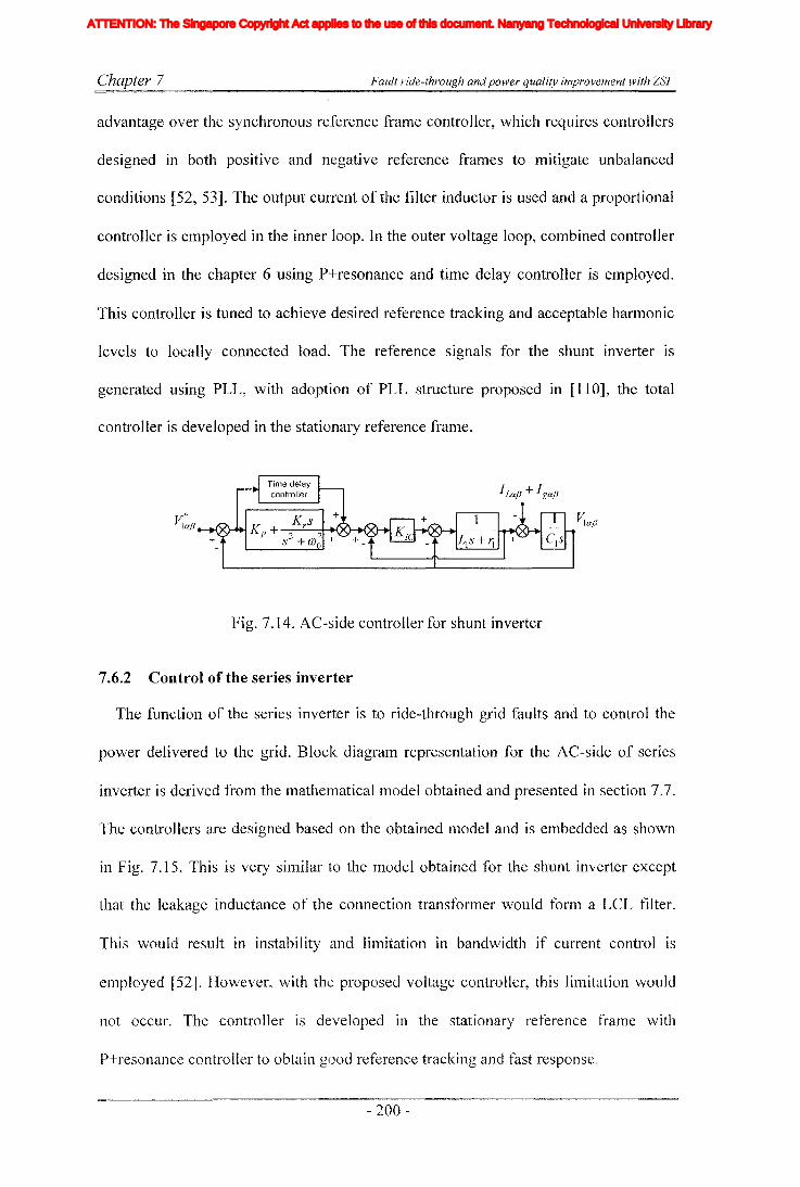
Chapter 7 Fault ride-through andpower quality improvement with ZSJ
advantage over the synchronous reference frame controller, which requires controllers
designed in both positive and negative reference fralTIeS to mitigate unbalanced
conditions [52, 53]. The output current of the filter inductor is used and a proportional
controller is employed in the inner loop. In the outer voltage loop, combined controller
designed in the chapter 6 using P+resonance and time delay controller is employed.
This controller is tuned to achieve desired reference tracking and acceptable harmonic
levels to locally connected load. The reference signals for the shunt inverter is
generated using PLL, with adoption of PLL structure proposed in [110], the total
controller is developed in the stationary reference frame.
~ajJ
Fig. 7.14. AC-side controller for shunt inverter
7.6.2 Control of the series inverter
The function of the series inverter is to ride-through grid faults and to control the
power delivered to the grid. Block diagram representation for the AC-side of series
inverter is derived from the mathematicallTIodel obtained and presented in section 7.7.
The controllers are designed based on the obtained model and is embedded as shown
in Fig. 7.15. This is very similar to the model obtained for the shunt inverter except
that the leakage inductance of the connection transformer would form a LCL filter.
This would result in instability and limitation in bandwidth if current control is
elTIployed [52]. However, with the proposed voltage controller, this limitation would
not occur. The controller is developed in the stationary reference fralne with
P+resonance controller to obtain good reference tracking and fast response.
- 200-
Iiq
Iod
Ioq
I odq
I max
1,Ie, Ici,Ic2IDC
IL_m
I MPP
IpvI scITHD
IzI Zn
lap*lap
Ia,Ip,IoIa *, Ip*,10*
Iah,Iphlin
12n
I;
afJ axis currentafJ axis reference currentafJO axis current componentsafJO axis reference current componentsafJ axis harmonic current componentsNeutral current of inverter 1Neutral current of inverter 2Zero sequence reference current
Average Z-source inductor currentPerturbed Z-source inductor current
Perturbed load currentConstantGain factor of fifth harmonics filterGain factor of seventh harmonics filterGain factor of eleventh harmonics filterDC side controller proportional gain of PI controllerDC side controller integral gain of PI controllerGain of the inverterIntegral gain of PI controller in current controllerGain of the hth resonance filterProportional gain of AC side inner loop controllerProportional gain of PI controller in current controllerProportional gain of zero sequence resonance controllerIntegral gain of the resonance controllerIntegral gain of the zero sequence resonance controllerIntegral gain of the hth resonance controllerProportional gain of AC side PI controllerIntegral gain of the AC side PI controllerMultiplying factor for harmonics eliminationDC side filter inductanceLoad inductanceNeutral inductanceGrid inductanceLeakage inductance of transformer
XVII
ATTENTION: The Singapore Copyright Act applies to the use of this document. Nanyang Technological University Library

Chapter 7 Fault ride-through and power quality improvement with ZSJ
Fig. 7.15. AC-side controller for series inverter
7.6.3 Power controlling
In this topology, power delivered to the grid is controlled by the series inverter. The
shunt inverter is synchronized with the grid. Therefore, the grid voltage and the shunt
inverter voltage vectors are aligned in normal operation. In fault condition, the output
voltage of the series inverter and the voltage drop across the connecting cable should
balance the voltage difference between the grid and the shunt inverter to avoid high
fault currents while controlling the power delivered to the grid. However, this
controller requires the knowledge of voltage at the PCC and the impedance of the
connecting cable (A.). In present day DG systems, the PCC voltage measurement is
readily available. With the recent advancement in communications technology, it
would be possible to obtain the PCC voltage measurement with sufficient bandwidth
using optical fibers or other comlTIunication channel. Fig. 7.16 shows the single line
diagram of the topology. By applying KVL and KCL, (7-8) and (7-9) can be obtained
and then by solving them (7-10) is obtained.
Fig. 7.16. Single line diagram of power circuit
- 201 -
Iiq
Iod
Ioq
I odq
I max
1,Ie, Ici,Ic2IDC
IL_m
I MPP
IpvI scITHD
IzI Zn
lap*lap
Ia,Ip,IoIa *, Ip*,10*
Iah,Iphlin
12n
I;
afJ axis currentafJ axis reference currentafJO axis current componentsafJO axis reference current componentsafJ axis harmonic current componentsNeutral current of inverter 1Neutral current of inverter 2Zero sequence reference current
Average Z-source inductor currentPerturbed Z-source inductor current
Perturbed load currentConstantGain factor of fifth harmonics filterGain factor of seventh harmonics filterGain factor of eleventh harmonics filterDC side controller proportional gain of PI controllerDC side controller integral gain of PI controllerGain of the inverterIntegral gain of PI controller in current controllerGain of the hth resonance filterProportional gain of AC side inner loop controllerProportional gain of PI controller in current controllerProportional gain of zero sequence resonance controllerIntegral gain of the resonance controllerIntegral gain of the zero sequence resonance controllerIntegral gain of the hth resonance controllerProportional gain of AC side PI controllerIntegral gain of the AC side PI controllerMultiplying factor for harmonics eliminationDC side filter inductanceLoad inductanceNeutral inductanceGrid inductanceLeakage inductance of transformer
XVII
ATTENTION: The Singapore Copyright Act applies to the use of this document. Nanyang Technological University Library
Chapter 7 Fault ride-through andpower quality improvement with ZSI
(7-8)
(7-9)
(7-10)
From (7-10), it is possible to see that the reference voltage to the series inverter
could be calculated from the two voltage measurements, grid current and impedance of
the connecting cable. Knowing the voltage at the PCC, it is possible to calculate the
desired grid current to deliver the required active and reactive power. In this context,
from the measured grid voltage, the positive sequence is extracted and then by using
the instantaneous power theory [31, 108] the reference currents to deliver desired
power can be derived. Then by substituting the reference grid current in (7-10), the
reference voltages for the series inverter can be obtained.
7.7 Simulation results
The simulations are carried out in Matlab/Simulink/PLECS toolboxes to show the
validity and the effectiveness of the proposed DO system and the controller. The
simulations are carried out on the circuit shown in Fig. 7.12. A combination of linear
and nonlinear load is used as the sensitive load. System parameters used in the
simulations are listed in Table 7.2. Modulation is done based on the simple shoot
through method proposed in chapter 5. A three. phase rectifier is used as the nonlinear
load injecting large amount of harmonics distorting the voltage quality at the local bus.
Fig. 7.17 shows the load current (ltoad) waveform while its harmonics spectrum is
given in Fig. 7.19. The load current produces THD1=19.880/0. However, with the use of
adopted controlleL voltage harmonic levels are kept below acceptable levels (see
hannonics spectruln in Fig. 7.20) with THD v of 2.670/0. This is achieved by varying
- 202 -
Iiq
Iod
Ioq
I odq
I max
1,Ie, Ici,Ic2IDC
IL_m
I MPP
IpvI scITHD
IzI Zn
lap*lap
Ia,Ip,IoIa *, Ip*,10*
Iah,Iphlin
12n
I;
afJ axis currentafJ axis reference currentafJO axis current componentsafJO axis reference current componentsafJ axis harmonic current componentsNeutral current of inverter 1Neutral current of inverter 2Zero sequence reference current
Average Z-source inductor currentPerturbed Z-source inductor current
Perturbed load currentConstantGain factor of fifth harmonics filterGain factor of seventh harmonics filterGain factor of eleventh harmonics filterDC side controller proportional gain of PI controllerDC side controller integral gain of PI controllerGain of the inverterIntegral gain of PI controller in current controllerGain of the hth resonance filterProportional gain of AC side inner loop controllerProportional gain of PI controller in current controllerProportional gain of zero sequence resonance controllerIntegral gain of the resonance controllerIntegral gain of the zero sequence resonance controllerIntegral gain of the hth resonance controllerProportional gain of AC side PI controllerIntegral gain of the AC side PI controllerMultiplying factor for harmonics eliminationDC side filter inductanceLoad inductanceNeutral inductanceGrid inductanceLeakage inductance of transformer
XVII
ATTENTION: The Singapore Copyright Act applies to the use of this document. Nanyang Technological University Library
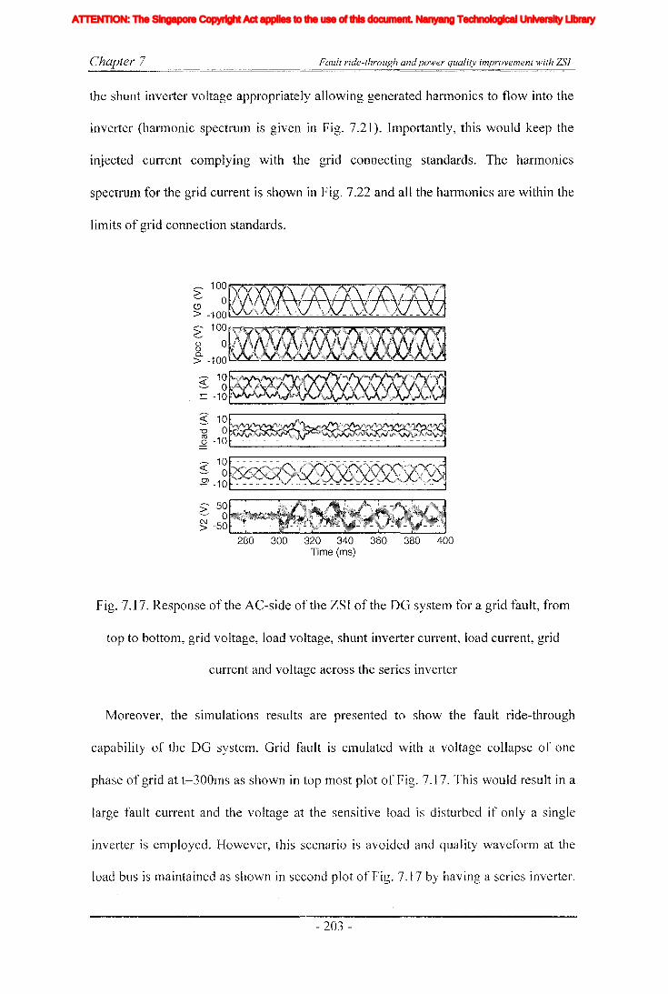
Chapter 7 Fault ride-through andpower quality improvement with ZSI
the shunt inverter voltage appropriately allowing generated harmonics to flow into the
inverter (hannonic spectrulTI is given in Fig. 7.21). Importantly, this would keep the
injected current complying with the grid connecting standards. The harmonics
spectrum for the grid current is shown in Fig. 7.22 and all the harmonics are within the
limits of grid connection standards.
___ 100>;- 01> -100 t.-'-......,;;;,-....;...o.;....;.;..-.~~..........::...-.=..-.....-...o::...-.;-....-....-~..;;;;.....;;..=....;:;;...;;;;...;:;;;...:
>' 100
g 0
g; -100
--- 10~ 0:= -10
"--------~--------'
~ 10
""0 o~~~~~ -10"------------------'--- 10~ o~SC~..Q> -10"-----------------'
280 300 320 340 360 380 400Time (ms)
Fig. 7.17. Response of the AC-side of the ZSI of the DG system for a grid fault, from
top to bottom, grid voltage, load voltage, shunt inverter current, load current, grid
current and voltage across the series inverter
Moreover, the simulations results are presented to show the fault ride-through
capability of the DG systenl. Grid fault is emulated with a voltage collapse of one
phase of grid at t=300ms as shown in top IllOst plot of Fig. 7.17. This would result in a
large fault current and the voltage at the sensitive load is disturbed if only a single
inverter is employed. However, this scenario is avoided and quality waveform at the
load bus is maintained as shown in second plot of Fig. 7.17 by having a series inverter.
Iiq
Iod
Ioq
I odq
I max
1,Ie, Ici,Ic2IDC
IL_m
I MPP
IpvI scITHD
IzI Zn
lap*lap
Ia,Ip,IoIa *, Ip*,10*
Iah,Iphlin
12n
I;
afJ axis currentafJ axis reference currentafJO axis current componentsafJO axis reference current componentsafJ axis harmonic current componentsNeutral current of inverter 1Neutral current of inverter 2Zero sequence reference current
Average Z-source inductor currentPerturbed Z-source inductor current
Perturbed load currentConstantGain factor of fifth harmonics filterGain factor of seventh harmonics filterGain factor of eleventh harmonics filterDC side controller proportional gain of PI controllerDC side controller integral gain of PI controllerGain of the inverterIntegral gain of PI controller in current controllerGain of the hth resonance filterProportional gain of AC side inner loop controllerProportional gain of PI controller in current controllerProportional gain of zero sequence resonance controllerIntegral gain of the resonance controllerIntegral gain of the zero sequence resonance controllerIntegral gain of the hth resonance controllerProportional gain of AC side PI controllerIntegral gain of the AC side PI controllerMultiplying factor for harmonics eliminationDC side filter inductanceLoad inductanceNeutral inductanceGrid inductanceLeakage inductance of transformer
XVII
ATTENTION: The Singapore Copyright Act applies to the use of this document. Nanyang Technological University Library
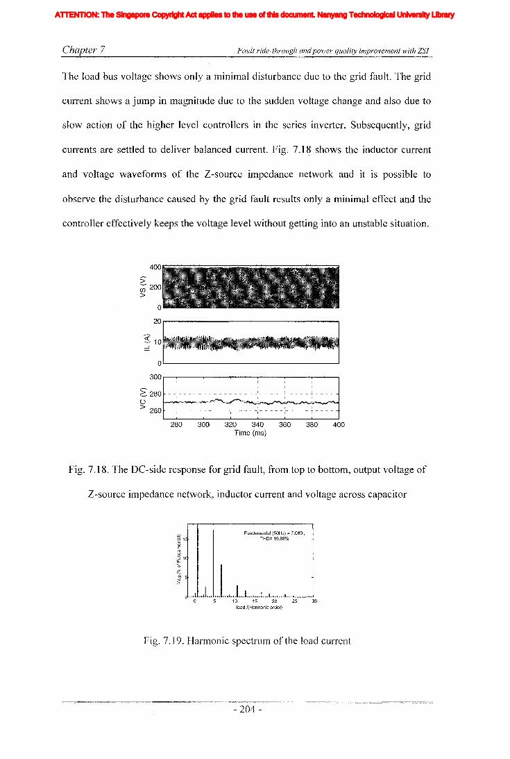
Chapter 7 Fault ride-through and power quality improvement with ZSI
The load bus voltage shows only a minimal disturbance due to the grid fault. The grid
current shows a jump in magnitude due to the sudden voltage change and also due to
slow action of the higher level controllers in the series inverter. Subsequently, grid
currents are settled to deliver balanced current. Fig. 7.18 shows the inductor current
and voltage waveforms of the Z-source impedance network and it is possible to
observe the disturbance caused by the grid fault results only a minimal effect and the
controller effectively keeps the voltage level without getting into an unstable situation.
I- "I - - -
I
I
- - ~ I
1
I
___. 1- ~
I I
o20,..-..----------------"
o'-----------------~
300 r---r-----r---...------r---.,.-----r----"
~ 280o> 260
:;--;;; 200>
280 300 320 340 360 380 400Time (ms)
Fig. 7.18. The DC-side response for grid fault, from top to bottom, output voltage of
Z-source impedance network, inductor current and voltage across capacitor
Fundamental (50Hz) ::: 7.089 ,< THD= 19.88%
(
5
0 .. J I I I I
10 15 20 25 30lIoad I(Harmonic order)
Fig. 7.19. Hannonic spectrum of the load current
- 204-
Iiq
Iod
Ioq
I odq
I max
1,Ie, Ici,Ic2IDC
IL_m
I MPP
IpvI scITHD
IzI Zn
lap*lap
Ia,Ip,IoIa *, Ip*,10*
Iah,Iphlin
12n
I;
afJ axis currentafJ axis reference currentafJO axis current componentsafJO axis reference current componentsafJ axis harmonic current componentsNeutral current of inverter 1Neutral current of inverter 2Zero sequence reference current
Average Z-source inductor currentPerturbed Z-source inductor current
Perturbed load currentConstantGain factor of fifth harmonics filterGain factor of seventh harmonics filterGain factor of eleventh harmonics filterDC side controller proportional gain of PI controllerDC side controller integral gain of PI controllerGain of the inverterIntegral gain of PI controller in current controllerGain of the hth resonance filterProportional gain of AC side inner loop controllerProportional gain of PI controller in current controllerProportional gain of zero sequence resonance controllerIntegral gain of the resonance controllerIntegral gain of the zero sequence resonance controllerIntegral gain of the hth resonance controllerProportional gain of AC side PI controllerIntegral gain of the AC side PI controllerMultiplying factor for harmonics eliminationDC side filter inductanceLoad inductanceNeutral inductanceGrid inductanceLeakage inductance of transformer
XVII
ATTENTION: The Singapore Copyright Act applies to the use of this document. Nanyang Technological University Library

Chapter 7 Fault ride-through and power quality improvement with ZSJ
Ol
~O.
Fundamental (50Hz) = 87.28,THD= 2.67%
10 15 20 25 30V1/(Harmonic order)
Fig. 7.20. Harmonic spectrum of the load bus voltage
~ 1
jLL
o
~Ol<ll
::;:
Fundamental (50Hz) = 10.23,
CTHO= 13.82%
8
6
4
/.
,I I .I0,. I • I
10 15 20 25 3011/(Harmonic order)
Fig. 7.21. Harmonic spectrum of the shunt inverter current
Fundamental (50Hz) '" 3.14,THD=4.29%
10 15 20 25 30Ig/(Harmonic order)
Fig. 7.22. Harmonic spectrum of the grid current
Fig. 7.23 shows the DC-side step response of the ZSI, where the input voltage (VDc)
is given a step response to emulate the characteristic of a renewable source. At
t=2001TIS, the input voltage is changed from 180 to 120V to disturb the system. When
the input voltage drops, in order to maintain a constant voltage across the capacitor,
the shoot-through time needs to be increased and the modulation index is subsequently
reduced to accommodate a larger shoot-through. The peak output voltage of Z-source
impedance network increased as shown in Fig. 7.23(top). I-Iowever, there is a
- 205 -
Iiq
Iod
Ioq
I odq
I max
1,Ie, Ici,Ic2IDC
IL_m
I MPP
IpvI scITHD
IzI Zn
lap*lap
Ia,Ip,IoIa *, Ip*,10*
Iah,Iphlin
12n
I;
afJ axis currentafJ axis reference currentafJO axis current componentsafJO axis reference current componentsafJ axis harmonic current componentsNeutral current of inverter 1Neutral current of inverter 2Zero sequence reference current
Average Z-source inductor currentPerturbed Z-source inductor current
Perturbed load currentConstantGain factor of fifth harmonics filterGain factor of seventh harmonics filterGain factor of eleventh harmonics filterDC side controller proportional gain of PI controllerDC side controller integral gain of PI controllerGain of the inverterIntegral gain of PI controller in current controllerGain of the hth resonance filterProportional gain of AC side inner loop controllerProportional gain of PI controller in current controllerProportional gain of zero sequence resonance controllerIntegral gain of the resonance controllerIntegral gain of the zero sequence resonance controllerIntegral gain of the hth resonance controllerProportional gain of AC side PI controllerIntegral gain of the AC side PI controllerMultiplying factor for harmonics eliminationDC side filter inductanceLoad inductanceNeutral inductanceGrid inductanceLeakage inductance of transformer
XVII
ATTENTION: The Singapore Copyright Act applies to the use of this document. Nanyang Technological University Library

Chapter 7 Fault ride-through andpower quality improvement with ZSl
significant transient in Vs resulting from the disturbance and it could be propagated
into the AC-side current. This is avoided by having a sufficient null interval and fast
AC-side controllers that can quickly adjust the modulation index to prevent the
propagation of the disturbance as presented in [18]. Fig. 7.24 shows the AC-side
response of the system voltages and currents and they are not affected by the
disturbance originated in the DC-side. Also it is possible to observe the presence of
distortion in the inductor currents resulting from the harmonics transferred from the
AC-side to the DC-side.
400,------,-..----------".==~
;;-;; 200>
o20,----'----------------.
~ 1011_Wl."~-WA~WIJ~tW-"-.J-,...:..:...,,.--"~~.-".~ ,.
0'-----------------'
~ ~~~r~ -~ ~ ~ -~ ~ ~ ~ ~ ~ ~ ~ :~ ~ ~ --.- ~ ~ ~ .. ~ --...~150 200 250 300 350
Time (ms)
Fig. 7.23. DC-side response to a step change of source voltage, from top to bottom,
output voltage of Z-source impedance network, inductor current and voltage across
capacitor
- 206-
Iiq
Iod
Ioq
I odq
I max
1,Ie, Ici,Ic2IDC
IL_m
I MPP
IpvI scITHD
IzI Zn
lap*lap
Ia,Ip,IoIa *, Ip*,10*
Iah,Iphlin
12n
I;
afJ axis currentafJ axis reference currentafJO axis current componentsafJO axis reference current componentsafJ axis harmonic current componentsNeutral current of inverter 1Neutral current of inverter 2Zero sequence reference current
Average Z-source inductor currentPerturbed Z-source inductor current
Perturbed load currentConstantGain factor of fifth harmonics filterGain factor of seventh harmonics filterGain factor of eleventh harmonics filterDC side controller proportional gain of PI controllerDC side controller integral gain of PI controllerGain of the inverterIntegral gain of PI controller in current controllerGain of the hth resonance filterProportional gain of AC side inner loop controllerProportional gain of PI controller in current controllerProportional gain of zero sequence resonance controllerIntegral gain of the resonance controllerIntegral gain of the zero sequence resonance controllerIntegral gain of the hth resonance controllerProportional gain of AC side PI controllerIntegral gain of the AC side PI controllerMultiplying factor for harmonics eliminationDC side filter inductanceLoad inductanceNeutral inductanceGrid inductanceLeakage inductance of transformer
XVII
ATTENTION: The Singapore Copyright Act applies to the use of this document. Nanyang Technological University Library

Chapter 7 Fault ride-through andpower quality improvement with ZSJ
~ 100
8 0~ -1001.:,.,;;.:~....;;....;;..~~;.....;.......;~~....;;....;;......;;....;;..~.;;."",;;.,..~-..;....;.-"'"
~
:; -10
~1
:: -1 L-- ---'
Fig. 7.24. AC-side response to a step change of source voltage, from top to bottom,
grid voltage, load voltage, shunt inverter current, load current, grid current and voltage
across the series inverter
7.8 Experimental results
The prototype of ZSI based power quality compensator is developed in the
laboratory to verify its performance with the proposed topology and control method.
The developed prototype is a scaled down model of an actual system and is shown in
Fig. 7.12 and its parameters values are listed in Table 7.2. A three phase AC power
supply connected to a resistive load bank is used to emulate the grid. A three phase
rectifier and a resistive bank are used as the sensitive load and non-linear load
respectively. The controllers are developed in dSPACE DSII03 based hardware
environment. The voltages and currents are measured using voltage and current
sensors and they are interfaced to the digital controller through AID converters. The
controllers are designed to generate six sinusoidal reference voltages and a constant
reference in synthesizing PWM signals and shoot-through signals respectively to
- 207 -
Iiq
Iod
Ioq
I odq
I max
1,Ie, Ici,Ic2IDC
IL_m
I MPP
IpvI scITHD
IzI Zn
lap*lap
Ia,Ip,IoIa *, Ip*,10*
Iah,Iphlin
12n
I;
afJ axis currentafJ axis reference currentafJO axis current componentsafJO axis reference current componentsafJ axis harmonic current componentsNeutral current of inverter 1Neutral current of inverter 2Zero sequence reference current
Average Z-source inductor currentPerturbed Z-source inductor current
Perturbed load currentConstantGain factor of fifth harmonics filterGain factor of seventh harmonics filterGain factor of eleventh harmonics filterDC side controller proportional gain of PI controllerDC side controller integral gain of PI controllerGain of the inverterIntegral gain of PI controller in current controllerGain of the hth resonance filterProportional gain of AC side inner loop controllerProportional gain of PI controller in current controllerProportional gain of zero sequence resonance controllerIntegral gain of the resonance controllerIntegral gain of the zero sequence resonance controllerIntegral gain of the hth resonance controllerProportional gain of AC side PI controllerIntegral gain of the AC side PI controllerMultiplying factor for harmonics eliminationDC side filter inductanceLoad inductanceNeutral inductanceGrid inductanceLeakage inductance of transformer
XVII
ATTENTION: The Singapore Copyright Act applies to the use of this document. Nanyang Technological University Library

Chapter 7 Fault ride-through andpower quality improvement with ZSI
modulate the ZSIs. A modulator board is designed to produce PWM signals and shoot-
through signals by comparing triangular carrier and reference signals. The generated
PWM and shoot-through signals are fed to an EPLD in which PWM signals are
modified to have shoot-through. Fig. 7.25 shows the obtained experimental results of
the prototype. The grid voltage is subjected to a single phase fault, where the voltage
of one phase is reduced by 80% to emulate a grid fault. Single phase measurements are
recorded in an oscilloscope and also three phase measurements of currents and
voltages are transferred into the dSPACE system and then recorded and plotted in
Matlab. From Fig. 7.25 it is observed that, when there is a grid fault, the load bus
voltage (second plot) is not disturbed. Moreover, it is possible to observe that the shunt
inverter output and injected grid currents do not show a large dip or a jump with the
controlling of the series inverter. This proves the good ride-through capability of the
proposed topology and the controller. Injected grid current shows a slight increase
following the grid fault due to the reduction of effective positive sequence grid voltage
and injected current is consequently increased by the current reference calculation loop
to deliver the specified power to the grid.
gil 1 "7 :zO:4006111s1Time (ms)
(a)
- 208-
2" Feb 200715:52:28
Iiq
Iod
Ioq
I odq
I max
1,Ie, Ici,Ic2IDC
IL_m
I MPP
IpvI scITHD
IzI Zn
lap*lap
Ia,Ip,IoIa *, Ip*,10*
Iah,Iphlin
12n
I;
afJ axis currentafJ axis reference currentafJO axis current componentsafJO axis reference current componentsafJ axis harmonic current componentsNeutral current of inverter 1Neutral current of inverter 2Zero sequence reference current
Average Z-source inductor currentPerturbed Z-source inductor current
Perturbed load currentConstantGain factor of fifth harmonics filterGain factor of seventh harmonics filterGain factor of eleventh harmonics filterDC side controller proportional gain of PI controllerDC side controller integral gain of PI controllerGain of the inverterIntegral gain of PI controller in current controllerGain of the hth resonance filterProportional gain of AC side inner loop controllerProportional gain of PI controller in current controllerProportional gain of zero sequence resonance controllerIntegral gain of the resonance controllerIntegral gain of the zero sequence resonance controllerIntegral gain of the hth resonance controllerProportional gain of AC side PI controllerIntegral gain of the AC side PI controllerMultiplying factor for harmonics eliminationDC side filter inductanceLoad inductanceNeutral inductanceGrid inductanceLeakage inductance of transformer
XVII
ATTENTION: The Singapore Copyright Act applies to the use of this document. Nanyang Technological University Library
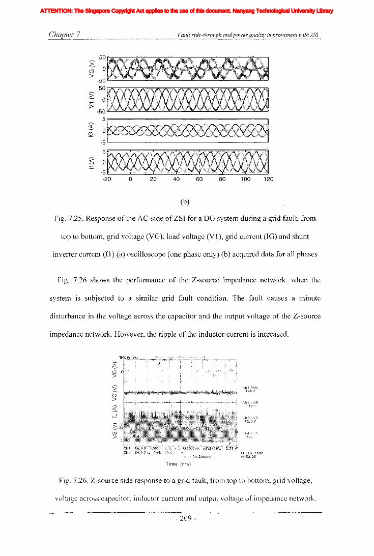
Chapter 7 Fault ride-through andpower quality improvement with ZSJ
12010080604020
502 0CJ>
-5050
>'--..-. 0~
>-50
5~ 0S:2
-5
5
~ 0~
-5 -
-20 0
(b)
Fig. 7.25. Response of the AC-side of ZSI for a DO system during a grid fault, from
top to bottom, grid voltage (VO), load voltage (VI), grid current (10) and shunt
inverter current (11) (a) oscilloscope (one phase only) (b) acquired data for all phases
Fig. 7.26 shows the performance of the Z-source impedance network, when the
system is subjected to a similar grid fault condition. The fault causes a minute
disturbance in the voltage across the capacitor and the output voltage of the Z-source
ilnpedance network. However, the ripple of the inductor current is increased.
~(J)
>
21 Feb 200715:52:28
Time (ms)
Fig. 7.26. Z-source side response to a grid fault, from top to bottom, grid voltage,
voltage across capacitor, inductor current and output voltage of inlpedance network.
- 209-
Iiq
Iod
Ioq
I odq
I max
1,Ie, Ici,Ic2IDC
IL_m
I MPP
IpvI scITHD
IzI Zn
lap*lap
Ia,Ip,IoIa *, Ip*,10*
Iah,Iphlin
12n
I;
afJ axis currentafJ axis reference currentafJO axis current componentsafJO axis reference current componentsafJ axis harmonic current componentsNeutral current of inverter 1Neutral current of inverter 2Zero sequence reference current
Average Z-source inductor currentPerturbed Z-source inductor current
Perturbed load currentConstantGain factor of fifth harmonics filterGain factor of seventh harmonics filterGain factor of eleventh harmonics filterDC side controller proportional gain of PI controllerDC side controller integral gain of PI controllerGain of the inverterIntegral gain of PI controller in current controllerGain of the hth resonance filterProportional gain of AC side inner loop controllerProportional gain of PI controller in current controllerProportional gain of zero sequence resonance controllerIntegral gain of the resonance controllerIntegral gain of the zero sequence resonance controllerIntegral gain of the hth resonance controllerProportional gain of AC side PI controllerIntegral gain of the AC side PI controllerMultiplying factor for harmonics eliminationDC side filter inductanceLoad inductanceNeutral inductanceGrid inductanceLeakage inductance of transformer
XVII
ATTENTION: The Singapore Copyright Act applies to the use of this document. Nanyang Technological University Library
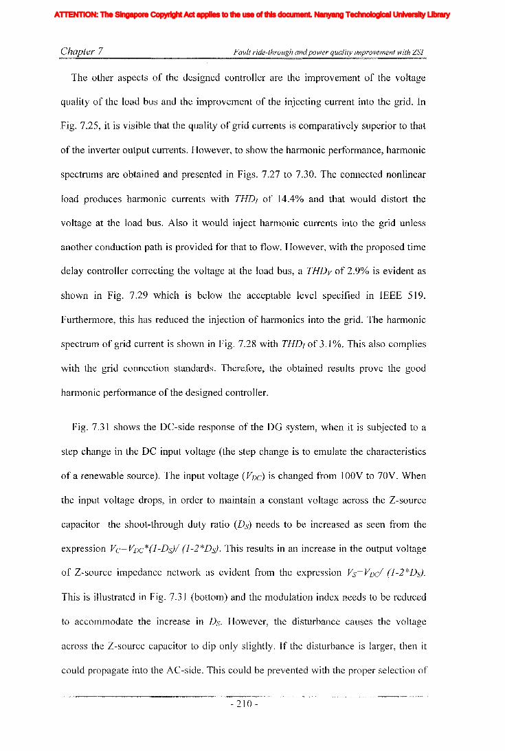
Chapter 7 Fault ride-through andpower quality improvement with ZSI
The other aspects of the designed controller are the improvement of the voltage
quality of the load bus and the improvement of the injecting current into the grid. In
Fig. 7.25, it is visible that the quality of grid currents is comparatively superior to that
of the inverter output currents. However, to show the harmonic performance, harmonic
spectrums are obtained and presented in Figs. 7.27 to 7.30. The connected nonlinear
load produces harmonic currents with THDJ of 14.4% and that would distort the
voltage at the load bus. Also it would inject harmonic currents into the grid unless
another conduction path is provided for that to flow. However, with the proposed time
delay controller correcting the voltage at the load bus, a THDv of 2.9% is evident as
shown in Fig. 7.29 which is below the acceptable level specified in IEEE 519.
Furthermore, this has reduced the injection of harmonics into the grid. The harmonic
spectrum of grid current is shown in Fig. 7.28 with THDJ of 3.1 %. This also complies
with the grid connection standards. Therefore, the obtained results prove the good
harmonic performance of the designed controller.
Fig. 7.31 shows the DC-side response of the DO system, when it is subjected to a
step change in the DC input voltage (the step change is to emulate the characteristics
of a renewable source). The input voltage (VDC) is changed from 1aav to 70V. When
the input voltage drops, in order to maintain a constant voltage across the Z-source
capacitor the shoot-through duty ratio (Ds) needs to be increased as seen from the
expression Vc=VDc*(l-Ds}/ (1-2*Ds). This results in an increase in the output voltage
of Z-source impedance network as evident from the expression Vs= VDc/ (1-2*Ds).
This is illustrated in Fig. 7.3] (bottom) and the modulation index needs to be reduced
to accomnlodate the increase in Ds. However, the disturbance causes the voltage
across the Z-source capacitor to dip only slightly. If the disturbance is larger, then it
could propagate into the AC-side. This could be prevented with the proper selection of
- 210 -
Iiq
Iod
Ioq
I odq
I max
1,Ie, Ici,Ic2IDC
IL_m
I MPP
IpvI scITHD
IzI Zn
lap*lap
Ia,Ip,IoIa *, Ip*,10*
Iah,Iphlin
12n
I;
afJ axis currentafJ axis reference currentafJO axis current componentsafJO axis reference current componentsafJ axis harmonic current componentsNeutral current of inverter 1Neutral current of inverter 2Zero sequence reference current
Average Z-source inductor currentPerturbed Z-source inductor current
Perturbed load currentConstantGain factor of fifth harmonics filterGain factor of seventh harmonics filterGain factor of eleventh harmonics filterDC side controller proportional gain of PI controllerDC side controller integral gain of PI controllerGain of the inverterIntegral gain of PI controller in current controllerGain of the hth resonance filterProportional gain of AC side inner loop controllerProportional gain of PI controller in current controllerProportional gain of zero sequence resonance controllerIntegral gain of the resonance controllerIntegral gain of the zero sequence resonance controllerIntegral gain of the hth resonance controllerProportional gain of AC side PI controllerIntegral gain of the AC side PI controllerMultiplying factor for harmonics eliminationDC side filter inductanceLoad inductanceNeutral inductanceGrid inductanceLeakage inductance of transformer
XVII
ATTENTION: The Singapore Copyright Act applies to the use of this document. Nanyang Technological University Library
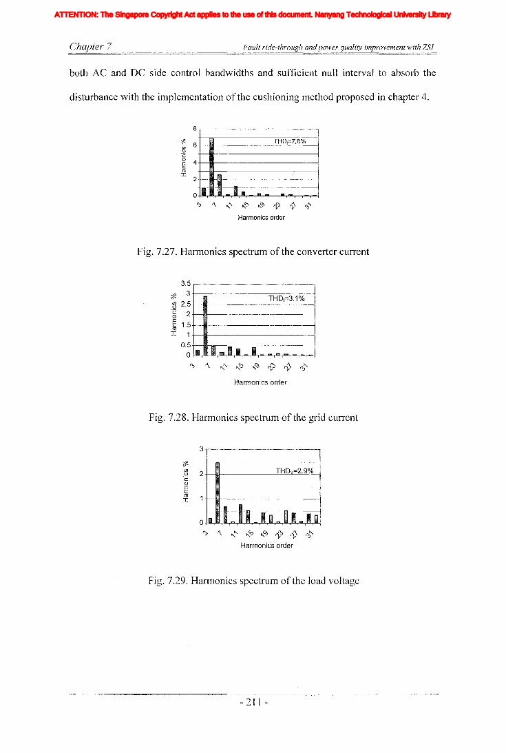
Chapter 7 Fault ride-through and power quality improvement with ZSJ
both AC and DC side control bandwidths and sufficient null interval to absorb the
disturbance with the ilTIplementation of the cushioning method proposed in chapter 4.
~ 6 THD1=7.8%t>
. 'c~ 4+--m------------IroI 2+--li1I-lilJ----------{
'\ ,," ,,~ ,,~ 't-O:> ~ 0:>"
Harmonics order
Fig. 7.27. Harmonics spectrum of the converter current
THD1=3.1-%
II Imlll II ....
3.5
~ 3~ 2.5'§ 2
E 1 5m .I 1
0.5
o~ '\ ,," ~ ,,~ cV V ~"
Harmonics order
Fig. 7.28. Harmonics spectrum of the grid current
~
~ 2 +-1llII- --..:T-:-H.:..;::::D-'t-=-=2=-:.c.9::e-.;.%...::.-0-I'coEroI
'\ ,," ,,~ ,,0.> cV 1- ~"
Harmonics order
Fig. 7.29. Harmonics spectrum of the load voltage
- 211 -
Iiq
Iod
Ioq
I odq
I max
1,Ie, Ici,Ic2IDC
IL_m
I MPP
IpvI scITHD
IzI Zn
lap*lap
Ia,Ip,IoIa *, Ip*,10*
Iah,Iphlin
12n
I;
afJ axis currentafJ axis reference currentafJO axis current componentsafJO axis reference current componentsafJ axis harmonic current componentsNeutral current of inverter 1Neutral current of inverter 2Zero sequence reference current
Average Z-source inductor currentPerturbed Z-source inductor current
Perturbed load currentConstantGain factor of fifth harmonics filterGain factor of seventh harmonics filterGain factor of eleventh harmonics filterDC side controller proportional gain of PI controllerDC side controller integral gain of PI controllerGain of the inverterIntegral gain of PI controller in current controllerGain of the hth resonance filterProportional gain of AC side inner loop controllerProportional gain of PI controller in current controllerProportional gain of zero sequence resonance controllerIntegral gain of the resonance controllerIntegral gain of the zero sequence resonance controllerIntegral gain of the hth resonance controllerProportional gain of AC side PI controllerIntegral gain of the AC side PI controllerMultiplying factor for harmonics eliminationDC side filter inductanceLoad inductanceNeutral inductanceGrid inductanceLeakage inductance of transformer
XVII
ATTENTION: The Singapore Copyright Act applies to the use of this document. Nanyang Technological University Library
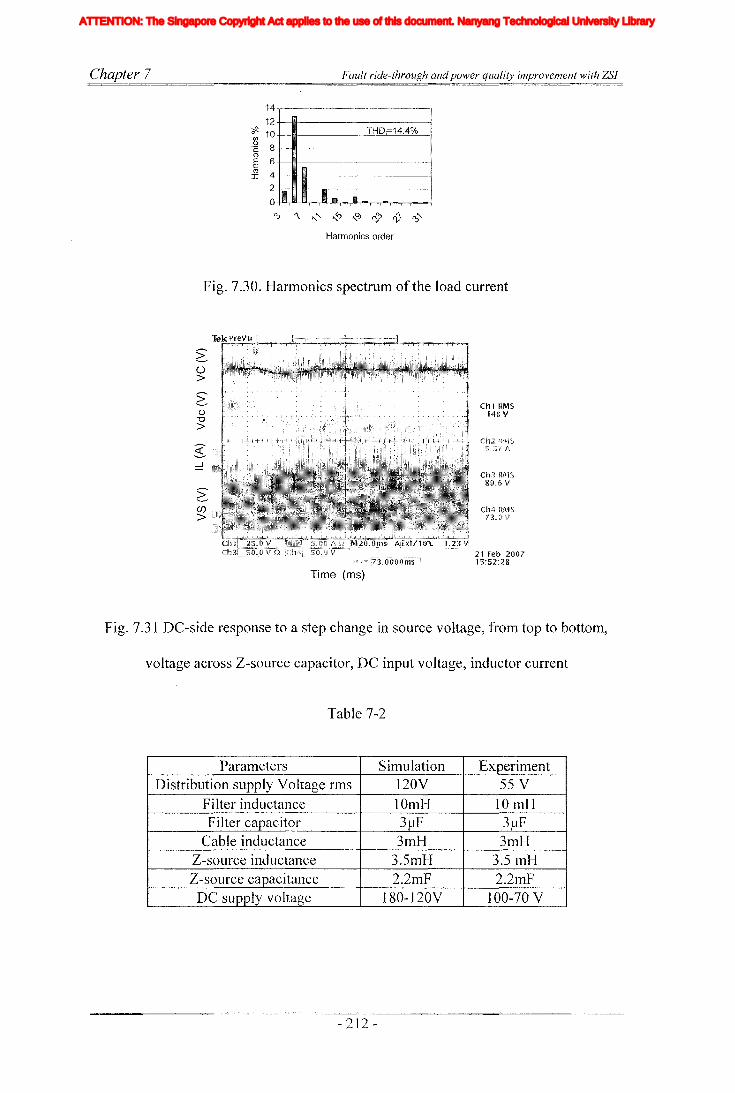
Chapter 7 Fault ride-through andpower quality improvement with ZSJ
14 -,-_M_'__'" '~'_"_~'_"_""_' '_"'""_"'"_"'"
12+__IWI---------____!
~ 10 THD=14.4% !
'~ 8 -t---mt--------------{oE 6+--IWI------~,--____!
~4+--~-----------!2 +__1i1I!l-Il1l---, -----____!
o-t""T"'"'T"".,.-.r,.,.,-,-.rJ........-r-r'''"-,--.--r''--r-i
0;) '\ ,.,."" ,.,.?) ,.,.0) rV tV 0;)""
Harmonics order
Fig. 7.30. Harmonics spectrum of the load current
~u>
G-u"'0>
~(j)
>
Time (ms)
ChI RMS14g V
21 Feb 200715:52:28
Fig. 7.31 DC-side response to a step change in source voltage, from top to bottom,
voltage across Z-source capacitor, DC input voltage, inductor current
Table 7-2
Parameters Simulation ExperimentDistribution supply Voltage rms 120V 55 V
Filter inductance 10mH 10mHFilter capacitor 3~lF 3~lF
Cable inductance 3mH 3mHZ-source inductance 3.5mH 3.51nHZ-source capacitance 2.2mF 2.2mF
DC supply voltage 180-120Y 100-70 Y
- 212 -
Iiq
Iod
Ioq
I odq
I max
1,Ie, Ici,Ic2IDC
IL_m
I MPP
IpvI scITHD
IzI Zn
lap*lap
Ia,Ip,IoIa *, Ip*,10*
Iah,Iphlin
12n
I;
afJ axis currentafJ axis reference currentafJO axis current componentsafJO axis reference current componentsafJ axis harmonic current componentsNeutral current of inverter 1Neutral current of inverter 2Zero sequence reference current
Average Z-source inductor currentPerturbed Z-source inductor current
Perturbed load currentConstantGain factor of fifth harmonics filterGain factor of seventh harmonics filterGain factor of eleventh harmonics filterDC side controller proportional gain of PI controllerDC side controller integral gain of PI controllerGain of the inverterIntegral gain of PI controller in current controllerGain of the hth resonance filterProportional gain of AC side inner loop controllerProportional gain of PI controller in current controllerProportional gain of zero sequence resonance controllerIntegral gain of the resonance controllerIntegral gain of the zero sequence resonance controllerIntegral gain of the hth resonance controllerProportional gain of AC side PI controllerIntegral gain of the AC side PI controllerMultiplying factor for harmonics eliminationDC side filter inductanceLoad inductanceNeutral inductanceGrid inductanceLeakage inductance of transformer
XVII
ATTENTION: The Singapore Copyright Act applies to the use of this document. Nanyang Technological University Library

Chapter 7
7.9 Discussion
Fault ride-through andpower quality improvement with ZSJ
The focus of this chapter is to study and develop ZSI based ride-through systems.
First section of the chapter presents a new DVR topology derived from ZSI where it'
would help sensitive load connected to the grid to ride-through a grid fault. This
enhances the capability of the DVR through better utilization of the stored energy. The
performances of developed DVR system and its controller are tested with simulations
and experiments using a prototype built in the laboratory. It is observed that the DVR
compensates the disturbance caused by voltage sags effectively while utilizing the
stored energy fully with the use of buck-boost capability of the proposed ZSI.
Secondly, ZSI based power quality compensator is developed to integrate renewable
energy sources into the grid. The proposed system consists of two inverters connected
into common Z-source impedance network. The shunt inverter functions as a UPS to
the locally connected load and also controllers are designed based on the negative
feedback time delay and P+resonance in the stationary reference frame. The combined
controller ilnproves the performance in terms of reference tracking and harmonic
quality improvement. The series inverter is operated to protect the system from grid
faults and directly controi the power delivered to the grid. A power controlling
algorithm is proposed based on the measured grid voltage. The AC-side controller of
series inverter designed in stationary reference frame is based on P+resonance
controller. The DC-side controller of ZSI is designed to change the shoot-through time
interval in order to maintain a constant voltage across the capacitors of Z-source
impedance network despite the changes in the supply voltage. The performance of the
designed controllers is proved with the simulations result obtained with
Matlab/Simulink/PLECS tool-boxes which shows good reference tracking, harmonics
- 213 -
Iiq
Iod
Ioq
I odq
I max
1,Ie, Ici,Ic2IDC
IL_m
I MPP
IpvI scITHD
IzI Zn
lap*lap
Ia,Ip,IoIa *, Ip*,10*
Iah,Iphlin
12n
I;
afJ axis currentafJ axis reference currentafJO axis current componentsafJO axis reference current componentsafJ axis harmonic current componentsNeutral current of inverter 1Neutral current of inverter 2Zero sequence reference current
Average Z-source inductor currentPerturbed Z-source inductor current
Perturbed load currentConstantGain factor of fifth harmonics filterGain factor of seventh harmonics filterGain factor of eleventh harmonics filterDC side controller proportional gain of PI controllerDC side controller integral gain of PI controllerGain of the inverterIntegral gain of PI controller in current controllerGain of the hth resonance filterProportional gain of AC side inner loop controllerProportional gain of PI controller in current controllerProportional gain of zero sequence resonance controllerIntegral gain of the resonance controllerIntegral gain of the zero sequence resonance controllerIntegral gain of the hth resonance controllerProportional gain of AC side PI controllerIntegral gain of the AC side PI controllerMultiplying factor for harmonics eliminationDC side filter inductanceLoad inductanceNeutral inductanceGrid inductanceLeakage inductance of transformer
XVII
ATTENTION: The Singapore Copyright Act applies to the use of this document. Nanyang Technological University Library

Chapter 7 Fault ride-through and power quality improvement with ZSI
performance and fault ride-through capability. The efficacy of the proposed topology
and controllers are validated with laboratory built prototype.
- 214 -
Iiq
Iod
Ioq
I odq
I max
1,Ie, Ici,Ic2IDC
IL_m
I MPP
IpvI scITHD
IzI Zn
lap*lap
Ia,Ip,IoIa *, Ip*,10*
Iah,Iphlin
12n
I;
afJ axis currentafJ axis reference currentafJO axis current componentsafJO axis reference current componentsafJ axis harmonic current componentsNeutral current of inverter 1Neutral current of inverter 2Zero sequence reference current
Average Z-source inductor currentPerturbed Z-source inductor current
Perturbed load currentConstantGain factor of fifth harmonics filterGain factor of seventh harmonics filterGain factor of eleventh harmonics filterDC side controller proportional gain of PI controllerDC side controller integral gain of PI controllerGain of the inverterIntegral gain of PI controller in current controllerGain of the hth resonance filterProportional gain of AC side inner loop controllerProportional gain of PI controller in current controllerProportional gain of zero sequence resonance controllerIntegral gain of the resonance controllerIntegral gain of the zero sequence resonance controllerIntegral gain of the hth resonance controllerProportional gain of AC side PI controllerIntegral gain of the AC side PI controllerMultiplying factor for harmonics eliminationDC side filter inductanceLoad inductanceNeutral inductanceGrid inductanceLeakage inductance of transformer
XVII
ATTENTION: The Singapore Copyright Act applies to the use of this document. Nanyang Technological University Library

Chapter 8 Conclusions and Recommendations
Chapter 8
Conclusions and Recommendations
8.1 Conclusions
With ever increasing energy demand, distributed generation has a major role in
tomorrow's power needs. Also with the exhaustion of hydro carbon reserves and
pressure by environmentalist to use green energy, there will be high demand for
unconventional energy sources. However, as studied in chapter 2, some of these
sources have large operating ranges under different source and load conditions that
delTIand power converters with wide operating range. Also after studying some of the
popularly used converter topologies, it can be concluded that some of the basic
topologies like VSI and CSI with limited operating ranges are unsuitable for
integration of renewable sources. However, two-stage front end converters that are
commonly based on VSI and CSI show increased losses and controlling difficulties.
These findings from the literature have emphasized the need of single stage converter
topologies in integration of popular DG sources. ZSI is a such single stage topology
that can operate in both buck and boost modes.
Although, the ZSI had been used for different applications, its dynamics have not
been studied in detail. The understanding of systelTI dynamics is essential in controller
designing. Therefore, the ZSI is modeled with state space averaging and sn1all-signal
analysis is done to obtain the transfer functions which are needed to design closed
loop controllers. The derived transfer functions have shown the presence of RHHP
zero and non-minilTIUlTI phase characteristics both in AC and DC sides. Moreover, it
was observed that the dynamics of derived transfer functions depend on the system
- 215 -
Iiq
Iod
Ioq
I odq
I max
1,Ie, Ici,Ic2IDC
IL_m
I MPP
IpvI scITHD
IzI Zn
lap*lap
Ia,Ip,IoIa *, Ip*,10*
Iah,Iphlin
12n
I;
afJ axis currentafJ axis reference currentafJO axis current componentsafJO axis reference current componentsafJ axis harmonic current componentsNeutral current of inverter 1Neutral current of inverter 2Zero sequence reference current
Average Z-source inductor currentPerturbed Z-source inductor current
Perturbed load currentConstantGain factor of fifth harmonics filterGain factor of seventh harmonics filterGain factor of eleventh harmonics filterDC side controller proportional gain of PI controllerDC side controller integral gain of PI controllerGain of the inverterIntegral gain of PI controller in current controllerGain of the hth resonance filterProportional gain of AC side inner loop controllerProportional gain of PI controller in current controllerProportional gain of zero sequence resonance controllerIntegral gain of the resonance controllerIntegral gain of the zero sequence resonance controllerIntegral gain of the hth resonance controllerProportional gain of AC side PI controllerIntegral gain of the AC side PI controllerMultiplying factor for harmonics eliminationDC side filter inductanceLoad inductanceNeutral inductanceGrid inductanceLeakage inductance of transformer
XVII
ATTENTION: The Singapore Copyright Act applies to the use of this document. Nanyang Technological University Library
Chapter 8 Conclusions and Recommendations
parameters. Furthermore, modulation index and shoot-through time depend on each
other. These could complicate the controller design by reducing the system robustness.
The system dynamics are studied with the use of pole zero diagrams by changing the
system parameters. However, it was found that effects of RHHP zero cannot be
eliminated by adjusting the Z-source parameters. Also, with open loop simulations and
experimental results, it is observed that non minimum phase characteristics cause the
response of ZSI under dynamic conditions to show large transients. It is observed that
these disturbances are transferred into the AC-side output voltage also.
After studying the dynamics of the DC-side impedance network, a multi loop'
controller is developed for stand-alone type DG system. Subsequently, a
comprehensive mathematical model is obtained by observing dynamical differences in
AC and DC sides of the ZSI, it is considered to be having a cOlnbination of fast and
slow system. Then, separate models and controllers are developed assuming the time
scale decoupling between them. The AC-side controllers are designed in synchronous
reference frame and load voltage is closed loop controlled with PI controllers and
measured capacitor current is used in the inner current loop. Designed controllers give
good reference tracking and disturbance rejection. The DC-side impedance network is
found to be a non minimum phase system with pulsating output voltage and these
would complicate the controller design. The controllers are designed with two loop
configuration to overcome the non-minimum phase limitation. The DC-side inductor
current is used as inner loop controller and output voltage of Z-source capacitor and
shoot-through duty ratio are used to predict the output voltage of the impedance
network. Then it is closed loop controlled with a PI controller. A cushioning method is
proposed to prevent the transferring of DC-side disturbance into the AC-side.
- 216 -
Iiq
Iod
Ioq
I odq
I max
1,Ie, Ici,Ic2IDC
IL_m
I MPP
IpvI scITHD
IzI Zn
lap*lap
Ia,Ip,IoIa *, Ip*,10*
Iah,Iphlin
12n
I;
afJ axis currentafJ axis reference currentafJO axis current componentsafJO axis reference current componentsafJ axis harmonic current componentsNeutral current of inverter 1Neutral current of inverter 2Zero sequence reference current
Average Z-source inductor currentPerturbed Z-source inductor current
Perturbed load currentConstantGain factor of fifth harmonics filterGain factor of seventh harmonics filterGain factor of eleventh harmonics filterDC side controller proportional gain of PI controllerDC side controller integral gain of PI controllerGain of the inverterIntegral gain of PI controller in current controllerGain of the hth resonance filterProportional gain of AC side inner loop controllerProportional gain of PI controller in current controllerProportional gain of zero sequence resonance controllerIntegral gain of the resonance controllerIntegral gain of the zero sequence resonance controllerIntegral gain of the hth resonance controllerProportional gain of AC side PI controllerIntegral gain of the AC side PI controllerMultiplying factor for harmonics eliminationDC side filter inductanceLoad inductanceNeutral inductanceGrid inductanceLeakage inductance of transformer
XVII
ATTENTION: The Singapore Copyright Act applies to the use of this document. Nanyang Technological University Library

Chapter 8 Conclusions and Recommendations
Disturbance rejection and reference tracking properties of proposed controllers are
validated with simulation results and prototype built in the laboratory.
Next, the focus of this thesis is given to the use of ZSIs to improve different other
aspects of power generation. Integration of these other functions could enhance the
popularity of DG systems and signify its role in power distribution. As many industrial
loads demand reliable energy sources on site generation has been found to be an
alternative for UPS systems. Towards this end, a grid connected paralleled ZSI based
DG system is proposed. This topology is designed to increase reliability and
maintainability while increasing the current capacity of the total system. A carrier
based modulation method is proposed and it is designed based on the simple shoot
through method with interleaved carrier signals. The modulation method is designed to
keep the modular independence. The AC-side controllers are designed to deliver
constant active and reactive power in the grid connected mode. In achieving that, a
balanced set of currents are injected to the grid. The current references are generated
using an outer power loop, where desired active, reactive power values and measured
grid voltages are used to calculate the current references. In the islanding mode, AC
side controllers are designed to supply a constant voltage to a locally connected load.
The load voltage is measured and controlled in closed loop manner. A controller
selector is designed to select the operating mode and also it provides reset signals to
integrators of the voltage controllers. This methodology would remove the saturation
in controller integrators and hence prevent large distortions in output voltage during
the transition. As a result, continuous supply is maintained at the local sensitive load.
This thesis has given emphasis to provide ancillary services to power system using
ZSI based DG systems. Power systems have power quality problems due to increased
- 217 -
Iiq
Iod
Ioq
I odq
I max
1,Ie, Ici,Ic2IDC
IL_m
I MPP
IpvI scITHD
IzI Zn
lap*lap
Ia,Ip,IoIa *, Ip*,10*
Iah,Iphlin
12n
I;
afJ axis currentafJ axis reference currentafJO axis current componentsafJO axis reference current componentsafJ axis harmonic current componentsNeutral current of inverter 1Neutral current of inverter 2Zero sequence reference current
Average Z-source inductor currentPerturbed Z-source inductor current
Perturbed load currentConstantGain factor of fifth harmonics filterGain factor of seventh harmonics filterGain factor of eleventh harmonics filterDC side controller proportional gain of PI controllerDC side controller integral gain of PI controllerGain of the inverterIntegral gain of PI controller in current controllerGain of the hth resonance filterProportional gain of AC side inner loop controllerProportional gain of PI controller in current controllerProportional gain of zero sequence resonance controllerIntegral gain of the resonance controllerIntegral gain of the zero sequence resonance controllerIntegral gain of the hth resonance controllerProportional gain of AC side PI controllerIntegral gain of the AC side PI controllerMultiplying factor for harmonics eliminationDC side filter inductanceLoad inductanceNeutral inductanceGrid inductanceLeakage inductance of transformer
XVII
ATTENTION: The Singapore Copyright Act applies to the use of this document. Nanyang Technological University Library

Chapter 8 Conclusions and Recommendations
penetration of nonlinear loads and single phase loads and grid faults. Therefore,
present day distribution systems are exposed to high levels of harmonics, unbalances
and zero sequence components. These could cause malfunction of loads and sources
connected to the grid. Particularly, their effects are pronounced under weak grid
conditions and also in small micro grid systems. Therefore, these effects have to be
rectified in the distribution level itself. However, installing dedicated systems like
APF, SVC or STATCOM devices are not economical. Therefore, this thesis has given
emphasis on integrating some of these ancillary services into ZSI based DG system.
Therein, two topologies are proposed in this thesis. First, a single ZSI and its
controller is designed to improve the harmonic quality of the power system. A new
combined controller is developed with P+resonance and negative feedback time delay
controllers to improve the harmonic quality and reference tracking. This controller is
implemented in stationary reference frame combining with P+resonance to iinprove its
fundamental tracking in digital implementation. ZSI based DG system is designed to
operate in two operating modes. First it would inject quality current into the grid when
it operates closer to full capacity and then when it operates below its ratings it is
designed to use the unused capacity for harmonic mitigation. A current limiting
algorithm is developed to select the constant factor which determines the level of
harmonics that can be mitigated. Then, two filtering techniques are proposed to be
used with proposed harmonic mitigation algorithms. The first method removes a
fraction of the entire harmonics that are present in the grid voltage, whereas in the
second method SOine particular harmonics are selected and this would be important
when certain specific hannonics need to be compensated. Secondly, four-leg
paralleled ZSI is proposed to enhance the reliability, maintainabil ity and to increase
capacity of the inverter systeln. All these benefits are achieved with the use of
- 218 -
Iiq
Iod
Ioq
I odq
I max
1,Ie, Ici,Ic2IDC
IL_m
I MPP
IpvI scITHD
IzI Zn
lap*lap
Ia,Ip,IoIa *, Ip*,10*
Iah,Iphlin
12n
I;
afJ axis currentafJ axis reference currentafJO axis current componentsafJO axis reference current componentsafJ axis harmonic current componentsNeutral current of inverter 1Neutral current of inverter 2Zero sequence reference current
Average Z-source inductor currentPerturbed Z-source inductor current
Perturbed load currentConstantGain factor of fifth harmonics filterGain factor of seventh harmonics filterGain factor of eleventh harmonics filterDC side controller proportional gain of PI controllerDC side controller integral gain of PI controllerGain of the inverterIntegral gain of PI controller in current controllerGain of the hth resonance filterProportional gain of AC side inner loop controllerProportional gain of PI controller in current controllerProportional gain of zero sequence resonance controllerIntegral gain of the resonance controllerIntegral gain of the zero sequence resonance controllerIntegral gain of the hth resonance controllerProportional gain of AC side PI controllerIntegral gain of the AC side PI controllerMultiplying factor for harmonics eliminationDC side filter inductanceLoad inductanceNeutral inductanceGrid inductanceLeakage inductance of transformer
XVII
ATTENTION: The Singapore Copyright Act applies to the use of this document. Nanyang Technological University Library

Chapter 8 Conclusions and Recommendations
designed modulation method and controllers which allow the modular implementation.
Particularly, this structure helps to mitigate zero sequence components that are present
in the grid. It would be an attractive topology as most of the distribution networks are
four wire systems. Also, a new control method is proposed to lnitigate the unbalanced
voltage using the unused capacity of the DG system. It is well known that unbalance
components cause severe problems in motor loads and generators. Particularly, this
could be important in distribution level where, there is no dedicated mitigation
equipments installed.
After studying harmonic and unbalance mitigation aspect of power conversion, the
focus is diverted to fault ride-through. This is identified as one of other major problem
faced by consumers and generating sources. It has been identified that, this problem
has two aspects, ride-through of loads and ride-through of sources with the occurrence
of grid faults. To overcome this, two ZSI based ride-through topologies are proposed.
Firstly, a ZSI based DVR system is proposed. Compared to a traditional DVR, the new
topology compensates the disturbances caused by sags effectively while utilizing the
stored energy effectively with the use of buck-boost capability of the ZSI.
Subsequently, a ZSI based power quality compensator is proposed to integrate
renewable energy sources into the grid. This topology is designed to serve multiple
power quality aspects, mainly it would ride-through faults and allow the energy source
to be connected to the grid even when there is a grid fault allowing the DG system to
meet the new grid connection standards. It is designed to supply continuous supply to
the local load and improve the voltage quality with designed controllers.
Perfoflllances of all the topologies and designed controllers are proved with the
simulation results obtained with Matlab/Silllulink/PLECS/PSIM tool-boxes. Obtained
- 2] 9 -
Iiq
Iod
Ioq
I odq
I max
1,Ie, Ici,Ic2IDC
IL_m
I MPP
IpvI scITHD
IzI Zn
lap*lap
Ia,Ip,IoIa *, Ip*,10*
Iah,Iphlin
12n
I;
afJ axis currentafJ axis reference currentafJO axis current componentsafJO axis reference current componentsafJ axis harmonic current componentsNeutral current of inverter 1Neutral current of inverter 2Zero sequence reference current
Average Z-source inductor currentPerturbed Z-source inductor current
Perturbed load currentConstantGain factor of fifth harmonics filterGain factor of seventh harmonics filterGain factor of eleventh harmonics filterDC side controller proportional gain of PI controllerDC side controller integral gain of PI controllerGain of the inverterIntegral gain of PI controller in current controllerGain of the hth resonance filterProportional gain of AC side inner loop controllerProportional gain of PI controller in current controllerProportional gain of zero sequence resonance controllerIntegral gain of the resonance controllerIntegral gain of the zero sequence resonance controllerIntegral gain of the hth resonance controllerProportional gain of AC side PI controllerIntegral gain of the AC side PI controllerMultiplying factor for harmonics eliminationDC side filter inductanceLoad inductanceNeutral inductanceGrid inductanceLeakage inductance of transformer
XVII
ATTENTION: The Singapore Copyright Act applies to the use of this document. Nanyang Technological University Library

Chapter 8 Conclusions and Recommendations
simulation results show good reference tracking, harmonic perfonnance and fault ride-
through capability. Subsequently, performances are further validated with laboratory
built prototypes.
8.2 Recommendations
The aim of this thesis is to study the ZSI as DG interfacing topology and to develop
control algorithms to supply quality output voltage to a locally connected load or inject
power to the grid. The proposed topologies and control algorithms are then used to\
improve different aspects of power generation and distribution. The design of
controllers for ZSI has two aspects, development of controllers for the DC-side and
development of control algorithms for AC-side. Two types of DC-side controlling
methods are proposed. Both of them are designed based on the obtained mathematical
model. Both have their merits but further improvements can be made. In the first
method, the designed controller doesn't operate in the optimum operating point all the
time, as modulation index is virtually fixed. At times, it could run at low modulation
index than what is possible. On the other hand it would apply only a known maxin1um
voltage stress on the switches. Also it has advantages of known saturation limits for
shoot-through and modulation index, which prevents the modulator moving into
region of other control variable. Therefore, it is easy to develop integrator anti-windup
loops for the DC and AC sides. With the second method, both modulation index and
shoot-through are varied to improve the utilization of the boosted voltage and reduce
the voltage stress on switches. However, the problem with this method is that it is
difficult set the saturation limits and design anti-windup loops for the controllers to
prevent each variable going into the others' region. On the other hand, when operated
in maximum boost it would lead to have non-minimum phase response in the AC side
- 220-
Iiq
Iod
Ioq
I odq
I max
1,Ie, Ici,Ic2IDC
IL_m
I MPP
IpvI scITHD
IzI Zn
lap*lap
Ia,Ip,IoIa *, Ip*,10*
Iah,Iphlin
12n
I;
afJ axis currentafJ axis reference currentafJO axis current componentsafJO axis reference current componentsafJ axis harmonic current componentsNeutral current of inverter 1Neutral current of inverter 2Zero sequence reference current
Average Z-source inductor currentPerturbed Z-source inductor current
Perturbed load currentConstantGain factor of fifth harmonics filterGain factor of seventh harmonics filterGain factor of eleventh harmonics filterDC side controller proportional gain of PI controllerDC side controller integral gain of PI controllerGain of the inverterIntegral gain of PI controller in current controllerGain of the hth resonance filterProportional gain of AC side inner loop controllerProportional gain of PI controller in current controllerProportional gain of zero sequence resonance controllerIntegral gain of the resonance controllerIntegral gain of the zero sequence resonance controllerIntegral gain of the hth resonance controllerProportional gain of AC side PI controllerIntegral gain of the AC side PI controllerMultiplying factor for harmonics eliminationDC side filter inductanceLoad inductanceNeutral inductanceGrid inductanceLeakage inductance of transformer
XVII
ATTENTION: The Singapore Copyright Act applies to the use of this document. Nanyang Technological University Library

Chapter 8 Conclusions and Recommendations
output voltage. Hence, to achieve the best operating conditions, a coordinated and
intelligent controlling of both the inverter and Z-source impedance network would be
necessary. Saturation 'levels and anti windup have to be designed to prevent the system
going into instability. Therefore, further research work needs to be done to investigate
the dynamics and design a controller.
In modeling the ZSI dynamics, the dynamics of energy source and storages has not
been considered in the thesis, and it is assumed the existence of good power
decoupling. Although these sources have common problem of having large operating
range, they have different dynamic characteristics. Therefore, modeling would be
more accurate if the dynamics of sources are considered. Also it is possible to obtain
different models for different sources like fuel cells, solar cells and wind turbines.
Then considering these dynamics, research can be further extended to develop
maximum power point tracking algorithms for application with ZSIs. This also needs
the understanding of the dynamics of different sources.
Another area of possible research would be on providing ancillary services to the
grid. It would be necessary to identify the limitations that could exist in particular
energy sources and effect on them. Therefore, further study is necessary considering
the different energy sources. In this thesis two control algorithms are developed
independently to mitigate harmonics and to mitigate unbalances and zero sequence
components. Obvious extension of this is to combine these two algorithms and derive
a common power quality compensation Inethodology. Furthermore, it would be
possible to develop optimization algorithms to utilize the excess capacity to mitigate
unbalances and harmonic components.
- 221 -
Iiq
Iod
Ioq
I odq
I max
1,Ie, Ici,Ic2IDC
IL_m
I MPP
IpvI scITHD
IzI Zn
lap*lap
Ia,Ip,IoIa *, Ip*,10*
Iah,Iphlin
12n
I;
afJ axis currentafJ axis reference currentafJO axis current componentsafJO axis reference current componentsafJ axis harmonic current componentsNeutral current of inverter 1Neutral current of inverter 2Zero sequence reference current
Average Z-source inductor currentPerturbed Z-source inductor current
Perturbed load currentConstantGain factor of fifth harmonics filterGain factor of seventh harmonics filterGain factor of eleventh harmonics filterDC side controller proportional gain of PI controllerDC side controller integral gain of PI controllerGain of the inverterIntegral gain of PI controller in current controllerGain of the hth resonance filterProportional gain of AC side inner loop controllerProportional gain of PI controller in current controllerProportional gain of zero sequence resonance controllerIntegral gain of the resonance controllerIntegral gain of the zero sequence resonance controllerIntegral gain of the hth resonance controllerProportional gain of AC side PI controllerIntegral gain of the AC side PI controllerMultiplying factor for harmonics eliminationDC side filter inductanceLoad inductanceNeutral inductanceGrid inductanceLeakage inductance of transformer
XVII
ATTENTION: The Singapore Copyright Act applies to the use of this document. Nanyang Technological University Library
Author's Publications
Author's Publications
International journal
1. C. 1. Gajanayake, D. M. Vilathgamuwa, and P. C. Loh, "Development of aComprehensive Model and a Multiloop Controller for Z-Source InverterDG Systems," IEEE Transactions on Industrial Electronics, vo1.54, no.4,pp.2352-2359, Aug. 2007
2. P. C. Loh, D. M. Vilathgamuwa, C. J. Gajanayake, Y. R. Lim, C. W. Teo,"Transient Modeling and Analysis of Pulse-Width Modulated Z-Sourceinverter," IEEE Transactions on Power Electronics, vo1.22, no.2, pp.498507, March 2007
3. P. C. Loh, D.M. Vilathgamuwa, C. J. Gajanayake, L. T. Wong, C. P. Ang,"Z-Source Current-Type Inverters: Digital Modulation and LogicImplementation," IEEE Transactions on Power Electronics, vo1.22, no.I,pp.169-177, Jan. 2007
4. C. 1. Gajanayake, D. M. Vilathgamuwa, and P. C. Loh, "Small-signal andsignal-flow-graph modeling of switched Z-source impedance network,"IEEE Power Electronics Letters, , vol.3, no.3, pp. 111-116, Sept. 2005
5. P. C. Loh, C. J. Gajanayake, D. M. VilathgalTIuwa, and F. Blaabjerg,"Evaluation of Resonant Damping Techniques for Z-Source Current-TypeInverter," IEEE Transactions on Power Electronics, vol. 23, pp. 2035-2043,2008.
6. D. M. Vilathgamuwa, C. J. Gajanayake, and P. C. Loh, " Modulation andcontrol of three phase paralleled Z-source inverters for distributedgeneration applications," accepted to publish in IEEE Transaction onEnergy conversion, 2008
7. C. J. Gajanayake, D. M. Vilathgamuwa, P. C. Loh, F. Blaabjerg, R.Teodorescu, "A Z-source inverter based flexible DG system with resonanceand repetitive controllers for power quality improvement of a weak grid,"Submitted to IEEE Transaction on Energy conversion
International conference
1. C. J. Gajanayake, D. M. Vilathgamuwa, P. C. Loh, F. Blaabjerg, and R.Teodorescu, "Z-source Inverter based Power Quality Compensator withEnhanced Ride-through," Conference Record of the IEEE IndustryApplications Conference, 42nd lAS Annual Meeting. 2007.
2. C. J. Gajanayake, R. Teodorescu, F. Blaabjerg, D. M. Vilathgamuwa, P. C.Loh, " Four-leg parallel Z-source inverter based DG systems to enhance the
- 222 -
Iiq
Iod
Ioq
I odq
I max
1,Ie, Ici,Ic2IDC
IL_m
I MPP
IpvI scITHD
IzI Zn
lap*lap
Ia,Ip,IoIa *, Ip*,10*
Iah,Iphlin
12n
I;
afJ axis currentafJ axis reference currentafJO axis current componentsafJO axis reference current componentsafJ axis harmonic current componentsNeutral current of inverter 1Neutral current of inverter 2Zero sequence reference current
Average Z-source inductor currentPerturbed Z-source inductor current
Perturbed load currentConstantGain factor of fifth harmonics filterGain factor of seventh harmonics filterGain factor of eleventh harmonics filterDC side controller proportional gain of PI controllerDC side controller integral gain of PI controllerGain of the inverterIntegral gain of PI controller in current controllerGain of the hth resonance filterProportional gain of AC side inner loop controllerProportional gain of PI controller in current controllerProportional gain of zero sequence resonance controllerIntegral gain of the resonance controllerIntegral gain of the zero sequence resonance controllerIntegral gain of the hth resonance controllerProportional gain of AC side PI controllerIntegral gain of the AC side PI controllerMultiplying factor for harmonics eliminationDC side filter inductanceLoad inductanceNeutral inductanceGrid inductanceLeakage inductance of transformer
XVII
ATTENTION: The Singapore Copyright Act applies to the use of this document. Nanyang Technological University Library
Author's Publications
grid performance under unbalanced conditions," In conf. of EuropeanPower Electronics Conference,. EPE '07, 2007
3. C. J. Gajanayake, D. M. Vilathgamuwa, P. C. Loh, F. Blaabjerg, R.Teodorescu, "A Z-source inverter based flexible DG system with resonanceand repetitive controllers for power quality improvement of a weak grid,"in conf. of 38th IEEE Power Electronics Specialists Conference. PESC '07.,2007
4. D. M. Vilathgamuwa, C. J. Gajanayake, P. C. Loh, and Y. W. Li, "VoltageSag Compensation with Z-Source Inverter Based Dynamic VoltageRestorer,". Conf. Record of 41st lAS Annual Meeting IEEE IndustryApplications Conference, vol.5, no., pp.2242-2248, 8-12 Oct. 2006
5. C. J. Gajanayake, D. M. Vilathgamuwa, P. C. Loh, "Modeling and designof multi-loop closed loop controller for Z-source inverter for DistributedGeneration," in conf. of 37th IEEE Power Electronics SpecialistsConference, PESC '06., vol., no., pp. 1-7, 18-22 June 2006
6. P. C. Loh, C. J. Gajanayake, D. M. Vilathgamuwa, F. Blaabjerg,"Evaluation of resonant damping techniques for Z-source current-typeinverter," Twenty-First Annual IEEE Applied Power ElectronicsConference and Exposition, APEC '06., vol., no., pp. 7 pp.-, 19-23 March2006
7. P. C. Loh, D. M. Vilathgamuwa, F. Gao, C.J. Gajanayake, L. W. Gay, P. F.Leong, "Random Pulse-Width Modulated Neutral-Paint-Clamped InverterWith Reduced Common-Mode Switching," in conf. of InternationalConference on Power Electronics and Drives Systems, PEDS 2005., vo1.2,no., pp. 1435-1440,28-01 Nov. 2005
8. P. C. Loh, D. M. Vilathganluwa, C. J. Gajanayake, Y. R. Lim, C. W. Teo,"Transient modeling and analysis of pulse-width modulated Z-sourceinverter," Conference Record of the IEEE Industry ApplicationsConference, 40th lAS Annual Meeting, vo1.4, no., pp. 2782-2789 Vol. 4, 2-6Oct. 2005
9. P. C. Loh, D. M. Vilathgamuwa, C. J. Gajanayake, L. T. Wong, C. P. Ang,"Z-source current-type inverters: digital modulation and logicimplementation," Conference Record o.f the IEEE Industry ApplicationsConference, Fourtieth lAS Annual Meeting. 2005 , vo1.2, no., pp. 940-947Vol. 2, 2-6 Oct. 2005
10. D. M. Vilathgamuwa, X. Wang, and C. J. Gajanayake, "Z-source converterbased grid-interface for variable-speed permanent magnet wind turbinegenerators," in Power Electronics Specialists Conference, 2008. PESC2008. IEEE, 2008, pp. 4545-4550
11. F. Gao, P. C. Loh, F. Blaabjerg, and C. J. Gajanayake, "Operationalanalysis and comparative evaluation of embedded Z-Source inverters," in
- 223 -
Iiq
Iod
Ioq
I odq
I max
1,Ie, Ici,Ic2IDC
IL_m
I MPP
IpvI scITHD
IzI Zn
lap*lap
Ia,Ip,IoIa *, Ip*,10*
Iah,Iphlin
12n
I;
afJ axis currentafJ axis reference currentafJO axis current componentsafJO axis reference current componentsafJ axis harmonic current componentsNeutral current of inverter 1Neutral current of inverter 2Zero sequence reference current
Average Z-source inductor currentPerturbed Z-source inductor current
Perturbed load currentConstantGain factor of fifth harmonics filterGain factor of seventh harmonics filterGain factor of eleventh harmonics filterDC side controller proportional gain of PI controllerDC side controller integral gain of PI controllerGain of the inverterIntegral gain of PI controller in current controllerGain of the hth resonance filterProportional gain of AC side inner loop controllerProportional gain of PI controller in current controllerProportional gain of zero sequence resonance controllerIntegral gain of the resonance controllerIntegral gain of the zero sequence resonance controllerIntegral gain of the hth resonance controllerProportional gain of AC side PI controllerIntegral gain of the AC side PI controllerMultiplying factor for harmonics eliminationDC side filter inductanceLoad inductanceNeutral inductanceGrid inductanceLeakage inductance of transformer
XVII
ATTENTION: The Singapore Copyright Act applies to the use of this document. Nanyang Technological University Library

Author's Publications
Power Electronics Specialists Conference, 2008. PESC 2008. IEEE, 2008,pp. 2757-2763.
Local journals and conference
1. C. J. Gajanayake, G. Ramtharan, G. K. Samaraweera, A. Atputharajah, 1.B. Ekanayake, "A Survey of harmonic currents at several industries in SriLanka," Journal of National Science Foundation Sri Lanka, vol 3 no.33 pp.205-217. 2005
2. C. J. Gajanayake, J. R. S. S. Kumara, M. K. M. Sana, M. A. R. M.Fernando, A. Atputharajah, "Under Voltage Problem in Sri Lanka: A CaseStudy," Annual Research Session, University of Peradeniya, Sri Lanka,2004
- 224-
Iiq
Iod
Ioq
I odq
I max
1,Ie, Ici,Ic2IDC
IL_m
I MPP
IpvI scITHD
IzI Zn
lap*lap
Ia,Ip,IoIa *, Ip*,10*
Iah,Iphlin
12n
I;
afJ axis currentafJ axis reference currentafJO axis current componentsafJO axis reference current componentsafJ axis harmonic current componentsNeutral current of inverter 1Neutral current of inverter 2Zero sequence reference current
Average Z-source inductor currentPerturbed Z-source inductor current
Perturbed load currentConstantGain factor of fifth harmonics filterGain factor of seventh harmonics filterGain factor of eleventh harmonics filterDC side controller proportional gain of PI controllerDC side controller integral gain of PI controllerGain of the inverterIntegral gain of PI controller in current controllerGain of the hth resonance filterProportional gain of AC side inner loop controllerProportional gain of PI controller in current controllerProportional gain of zero sequence resonance controllerIntegral gain of the resonance controllerIntegral gain of the zero sequence resonance controllerIntegral gain of the hth resonance controllerProportional gain of AC side PI controllerIntegral gain of the AC side PI controllerMultiplying factor for harmonics eliminationDC side filter inductanceLoad inductanceNeutral inductanceGrid inductanceLeakage inductance of transformer
XVII
ATTENTION: The Singapore Copyright Act applies to the use of this document. Nanyang Technological University Library
Bibliography
Bibliography
[1] Y. W. Li, D. M. Vilathgamuwa, and P. C. Loh, "A grid-interfacing powerquality compensator for three-phase three-wire microgrid applications," IEEETrans. on Power Electronics, vo!.21, no. 4, pp. 1021-1031 July 2006.
[2] F. Blaabjerg, Z. Chen, and S. B. Kjaer, "Power electronics as efficient interfacein dispersed power generation systems," IEEE Transactions on PowerElectronics, vol. 19, pp. 1184-1194 2004.
[3] N. Jenkins, R. Allan, P. Crossley, D. Kirschen, and G. Strbac, EmbeddedGeneration: London: lEE, 2000.
[4] M. N. Marwali, J.-W. Jung, and A. Keyhani, "Control of distributed generationsystems - Part II: Load sharing control," IEEE Transactions on PowerElectronics, vo1.19, no. 6, pp. 1551-1561 Nov.2004.
[5] M. N. Marwali, J.-W. Jung, and A. Keyhani, "Stability Analysis of LoadSharing Control for Distributed Generation Systems," IEEE Transaction onEnergy Conversion, vol.22, no. 3, pp. 737-745 Sept. 2007.
[6] M. N. Marwali and A. Keyhani, "Control of distributed generation systemsPart I: Voltages and currents control," IEEE Transactions on PowerElectronics, vol.19, no. 6, pp. 1541-1550, Nov. 2004.
[7] C. J. Hatziadoniu, A. A. Lobo, F. Pourboghrat, and M. Daneshdoost, "Asimplified dynamic model of grid-connected fuel-cell generators," IEEETransactions on Power Delivery, vol. 17, pp. 467-473 2002.
[8] E. Santi, D. Franzoni, A. Monti, D. Patterson, F. Ponci, and N. Barry, "A fuelcell based domestic uninterruptible power supply," in Proc. of SeventeenthAnnual IEEE Applied Power Electronics Conference and Exposition, APEC,2002.
[9] J. Wang, F. Z. Peng, 1. Anderson, A. Joseph, and R. Buffenbarger, "Low costfuel cell converter system for residential power generation," IEEETransactions on Power Electronics, vol. 19, pp. 1315-1322, 2004.
[10] N. Yamamura, M. Ishida, and T. Hori, "A Simple Wind Power GeneratingSystem with Permanent Magnet Type Synchronous Generator," in Proc. ofIEEE International Conference on Power Electronics and Drive Systems,PEDS'99, 1999.
[11] F. Blaabjerg and Z. Chen, "Synthesis Lecture Series on Power Electronics:Power electronics for modern win turbines" USA: Morgan & ClaypoolPublisher's 2006.
[12] F. Blaabjerg and Z. Chen, Power electronics for modern wind turbines: SanRafael, Calif. :Morgan & Claypool Publishers, 2006.
[13] Z. Chen and E. Spooner, "Simulation of a direct drive variable speed energyconverter," in Proc. of Int. Con.f Electrical Machines, Istanbul, Turkey, pp.2045-2050., 1998.
[14] F. Z. Peng, HZ-source inverter," IEEE Transactions on Industry Applications,vol. 39, pp. 504-510, 2003.
[15] F. Z. Peng, A. Joseph, 1. Wang, M. Shen, L. Chen, Z. Pan, E. Ortiz-Rivera, andY. Huang, "Z-Source Inverter for Motor Drives," IEEE Transactions on PowerElectronics, vol. 20, pp. 857-863, 2005.
[16] F. Z. Peng, X. Yuan, X. Fang, and Z. Qian, "Z-source inverter for adjustablespeed drives," IEEE Power Electronics Letters, vol. 1, pp. 33-35, 2003.
- 225 -
Iiq
Iod
Ioq
I odq
I max
1,Ie, Ici,Ic2IDC
IL_m
I MPP
IpvI scITHD
IzI Zn
lap*lap
Ia,Ip,IoIa *, Ip*,10*
Iah,Iphlin
12n
I;
afJ axis currentafJ axis reference currentafJO axis current componentsafJO axis reference current componentsafJ axis harmonic current componentsNeutral current of inverter 1Neutral current of inverter 2Zero sequence reference current
Average Z-source inductor currentPerturbed Z-source inductor current
Perturbed load currentConstantGain factor of fifth harmonics filterGain factor of seventh harmonics filterGain factor of eleventh harmonics filterDC side controller proportional gain of PI controllerDC side controller integral gain of PI controllerGain of the inverterIntegral gain of PI controller in current controllerGain of the hth resonance filterProportional gain of AC side inner loop controllerProportional gain of PI controller in current controllerProportional gain of zero sequence resonance controllerIntegral gain of the resonance controllerIntegral gain of the zero sequence resonance controllerIntegral gain of the hth resonance controllerProportional gain of AC side PI controllerIntegral gain of the AC side PI controllerMultiplying factor for harmonics eliminationDC side filter inductanceLoad inductanceNeutral inductanceGrid inductanceLeakage inductance of transformer
XVII
ATTENTION: The Singapore Copyright Act applies to the use of this document. Nanyang Technological University Library

Bibliography
[17] J.-W. Jung, M. Dai, and A. Keyhani, "Modeling and control ofa fuel cell basedZ-source converter," in Proc. of Twentieth Annual IEEE Applied PowerElectronics Conference and Exposition, APEC, 2005.
[18] C. J. Gajanayake, D. M. Vilathgamuwa, and P. C. Loh, "Development of aComprehensive Model and a Multiloop Controller for Z-Source Inverter DGSystems," IEEE Transactions on Industrial Electronics, vo!.54, no. 4, pp.23522359,2007.
[19] N. Pogaku and T. C. Green, "Harmonic mitigation throughout a distributionsystem: a distributed-generator-based solution," lEE Proc.-Gener. Transm.Distrib., Vol. 153, No.3, May 2006.
[20] M. Hojo and T. Ohnishi, "Adjustable Harmonic Mitigation for Grid-ConnectedPhotovoltaic System Utilizing Surplus Capacity of Utility Interactive Inverter,"in Proc. of 37th IEEE Power Electronics Specialists Conference, PESC '06,vo!., no., pp. 1-6, 18-22, June 2006.
[21] T. Ohnishi and M. Hojo, tlAC line voltage harmonics compensator withexcessive current control," IEEE Transactions on Industrial Electronics,vo1.50, no. 6, pp. 1126-1133, Dec. 2003.
[22] "IEEE recommended practices and requirements for harmonic control inelectrical power systelTIS,tI IEEE Std 519-1992, 1993.
[23] tlIEEE Recommended Practice for Utility Interface of Photovoltaic (PV)Systems," IEEE Std 929-2000, 2000.
[24] tlElectromagnetic Compatibility (EMC) - Part 3-4: Limits - Limitation ofEmission of Harmonic Currents in Low-Voltage Power Supply Systems forEquipment with Rated Current Greater Than 16 A,tI IEC 61000, 1998.
[25] D. Hongfa, D. Xianzhong, and H. Yangzan, "A novel compensator forunbalanced three phase distribution feeders," in Proc. of IEEE PowerEngineering Society Winter Meeting, vo!.4, pp.2379-2384, 2000.
[26] K. Li, J. Liu, G. Zhao, and Z. Wang, tlA transformerless 2-level inverter basedstatic var generator with multiple functions in medium voltage applications, tI inin Proc. of 41st Annual Meeting IEEE Industry Applications Conference,IAS06, 2006.
[27] S. S. Choi, B. H. Li, and D. M. Vilathgamuwa, tlDynamic voltage restorationwith minimum energy injection," IEEE Trans. Power Systems, vo!. 15, pp. 5157,2000.
[28] P. Krein, Elements ofPower Electronics: New York: Oxford University Press,1998.
[29] T. Jimichi, H. Fujita, and H. Akagi, "Design and experimentation of a dynamicvoltage restorer capable of significantly reducing an energy-storage element,"in Proc. of 14th Annual Meeting IEEE Industry Applications Conference,IAS05, 2005.
[30] L. Asiminoaei, F. Blaabjerg, S. Hansen, and P. Thoegersen, "Adaptivecompensation of reactive power with shunt active power filters," in Proc. of41st Annual Meeting IEEE Industry Applications Society IAS06, 2006.
[31] M. P. Kazmierkowski, R. Krishnan, and F. Blaabjerg, Control in powerelectronics: selectedproblems: AITIsterdam ; Boston: Academic Press, 2002.
[32] J. Lee, J. Kim, J. Kwon, and K. NaIll, "Two DOF controller for paralleloperation of fuel cell power generator with power grid," in Proc. ofFourtiethAnnual Meeting IEEE Industry Applications Conference, IAS05, Oct. 2005.
- 226-
Iiq
Iod
Ioq
I odq
I max
1,Ie, Ici,Ic2IDC
IL_m
I MPP
IpvI scITHD
IzI Zn
lap*lap
Ia,Ip,IoIa *, Ip*,10*
Iah,Iphlin
12n
I;
afJ axis currentafJ axis reference currentafJO axis current componentsafJO axis reference current componentsafJ axis harmonic current componentsNeutral current of inverter 1Neutral current of inverter 2Zero sequence reference current
Average Z-source inductor currentPerturbed Z-source inductor current
Perturbed load currentConstantGain factor of fifth harmonics filterGain factor of seventh harmonics filterGain factor of eleventh harmonics filterDC side controller proportional gain of PI controllerDC side controller integral gain of PI controllerGain of the inverterIntegral gain of PI controller in current controllerGain of the hth resonance filterProportional gain of AC side inner loop controllerProportional gain of PI controller in current controllerProportional gain of zero sequence resonance controllerIntegral gain of the resonance controllerIntegral gain of the zero sequence resonance controllerIntegral gain of the hth resonance controllerProportional gain of AC side PI controllerIntegral gain of the AC side PI controllerMultiplying factor for harmonics eliminationDC side filter inductanceLoad inductanceNeutral inductanceGrid inductanceLeakage inductance of transformer
XVII
ATTENTION: The Singapore Copyright Act applies to the use of this document. Nanyang Technological University Library
Bibliography
[33J X. Yu, M. R. Starke, L. M. Tolbert, and B. Ozpineci, "Fuel cell powerconditioning for electric power applications: a summary," lET Electric PowerApplications, vo!.l, no. 5, pp.643-656, Sept. 2007.
[34] P. Xu, X. Zhang, C. Zhang, R. Cao, and L. Chang, "Study of Z-Source Inverterfor Grid-Connected PV Systems," in Proc. of 37th IEEE Power ElectronicsSociety conference, PESC '06, vo!., no.pp. 1- 5, 18-22,2006.
[35] M. A. Laughton, "Fuel cells," IEEE Power Engineering Journal , vo1.16, no.1,pp.37-47, Feb 2002.
[36] W. Choi, P. N. Enjeti, and J. W. Howze, "Development of an equivalent circuitmodel of a fuel cell to evaluate the effects of inverter ripple current, ft in Proc.of Nineteenth Annual IEEE Applied Power Electronics Conference andExposition, APEC '04. vo!.l, no., pp. 355-361, 2004.
[37] R. Teodorescu, F. Blaabjerg, U. Borup, and M. Liserre, "A new controlstructure for grid-connected LCL PV inverters with zero steady-state error andselective harmonic compensation," in Proc. of Nineteenth Annual IEEEApplied Power Electronics Conference and Exposition. APEC '04,2004.
[38] M. Thomson and D. G. Infield, "Impact of widespread photovoltaicsgeneration on distribution systems," lET, Renewable Power Generation, vo!.l,no. 1, pp.33-40, March 2007.
[39] A. Burke, "Ultracapacitors: why, how, and where is the technology," Journalofpower source, Vol. 91,pp. 37-55, 2000.
[40J Y. H. Kim, H. W. Moon, S. H. Kim, E. J. Cheong, and C. Y. Won, "A fuel cellsystem with Z-source inverters and ultracapacitors," in Proc. of The 4thInternational Power Electronics and Motion Control Conference, IPEMC2004. vol. 3, no.,pp. 1587-1591, Aug. 2004.
[41] G. Ledwich and T. A. George, "Negative-phase-sequence reduction withadjacent static reactive compensators," lEE proc: - Electr. Power App!., Vol,141, No 5, September 1994.
[42] M. 1. Marei, E. F. EI-Saadany, and M. M. A. Salama, "A novel controlalgorithm for the DG interface to mitigate power quality problems," IEEETransactions on Power Delivery, vol. 19, pp. 1384-1392, 2004.
[43] N. A. Samra, C. Neft, A. Sundaram, and W. Malcolm, "The distribution systen1dynamic voltage restorer and its applications at industrial facilities withsensitive loads," in Proc. of Power Conversion Intell. Motion Power QualityLong Beach, CA, Sept. 1995.
[44J N. Mohan, T. M. Undeland, and W. P. Robbins, Power Electronics:Converters, application and design, 2003.
[45] S. D. Round, Q. Yu, L. E. Norum, and T. M. Undeland, "Performance Of AUnified Power Flow Controller Using A D-Q Control System," in Proc. ofSixth International Conference on AC and DC Power Transmission, (Co,?!Pub!. No. 423), 1996.
[46] G. Escobar, P. Mattavelli, A. M. Stankovic, A. A. Valdez, and J. LeyvaRamos, "An Adaptive Control for UPS to Compensate Unbalance andHarmonic Distortion Using a Combined Capacitor/Load Current Sensing,"IEEE Transactions on Industrial Electronics, vol. 54, no.2, pp.839-847, April2007.
[47] L. Asilnmoaei, E. Aeloiza, 1. H. Kim, P. Enjeti, F. Blaabjerg, L. T. Moran, andS.K. SuI, "An interleaved active power filter with reduced size of passivecomponents," in Proc. of Twenty-First Annual IEEE Applied PowerElectronics Conference and Exposition, APEC~ '06, 2006.
- 227 -
Iiq
Iod
Ioq
I odq
I max
1,Ie, Ici,Ic2IDC
IL_m
I MPP
IpvI scITHD
IzI Zn
lap*lap
Ia,Ip,IoIa *, Ip*,10*
Iah,Iphlin
12n
I;
afJ axis currentafJ axis reference currentafJO axis current componentsafJO axis reference current componentsafJ axis harmonic current componentsNeutral current of inverter 1Neutral current of inverter 2Zero sequence reference current
Average Z-source inductor currentPerturbed Z-source inductor current
Perturbed load currentConstantGain factor of fifth harmonics filterGain factor of seventh harmonics filterGain factor of eleventh harmonics filterDC side controller proportional gain of PI controllerDC side controller integral gain of PI controllerGain of the inverterIntegral gain of PI controller in current controllerGain of the hth resonance filterProportional gain of AC side inner loop controllerProportional gain of PI controller in current controllerProportional gain of zero sequence resonance controllerIntegral gain of the resonance controllerIntegral gain of the zero sequence resonance controllerIntegral gain of the hth resonance controllerProportional gain of AC side PI controllerIntegral gain of the AC side PI controllerMultiplying factor for harmonics eliminationDC side filter inductanceLoad inductanceNeutral inductanceGrid inductanceLeakage inductance of transformer
XVII
ATTENTION: The Singapore Copyright Act applies to the use of this document. Nanyang Technological University Library

Bibliography
[48] C.-C. Yeh and M. D. Manjrekar, itA Reconfigurable Uninterruptible PowerSupply System for Multiple Power Quality Applications," IEEE Transactionson Power Electronics, vo!.22, no. 4, pp.1361-1372, July 2007.
[49] B. Wang and G. Venkataramanan, "Operation and Control of a DynamicVoltage Restorer Realized Using Cascaded H-Bridge Converters," in Proc. of36th IEEE Power Electronics Specialists Conference, PESC; '05. vol.l1no. 14, pp. 2222-2229, Sept. 2005.
[50] Y. Ye, M. Kazerani, and V. H. Quintana, ItModeling, control andimplementation of three-phase PWM converters," IEEE Transactions onPower Electronics, vol. 18, pp. 857-864,2003.
[51] P. C. Loh, D. M. Vilathgamuwa, Y. S. Lai, G. T. Chua, and Y. Li, ItPulsewidth modulation of Z-source inverters," in Proc. of 39th Annual IEEEIndustry Applications Conference, IAS04, 2004.
[52] E. Twining and D. G. Holmes, ItGrid current regulation of a three-phasevoltage source inverter with an LCL input filter, It IEEE Transactions on PowerElectronics, vol. 18, pp. 888-895, 2003.
[53] Y. Li, D. M. Vilathgamuwa, and P. C. Loh, "Design, analysis, and real-timetesting of a controller for multibus microgrid system," IEEE Transactions onPower Electronics, vol. 19, pp. 1195-1204, 2004.
[54] J. R. Espinoza, G. Joos, and P. D. Ziogas, itA general purpose voltage regulatedcurrent-source inverter power supply," in Proc. of Eighth Annual AppliedPower Electronics Conference and Exposition, APEC '93, 1993.
[55] D. N. Zmood and D. G. Holmes, "Improved voltage regulation for currentsource inverters," IEEE Transactions on Industry Applications, vol. 37, pp.1028-1036,2001.
[56] G. Ledwich, "Current source inverter modulation," IEEE Transactions onPower Electronics, vol. 6, pp. 618-623 1991.
[57] A. M. Tuckey and J. N. Krase, itA low-cost inverter: for domestic fuel cellapplications," in Proc. of 33rd Annual IEEE Power Electronics SpecialistsConference, PESC 02,2002.
[58] R. Gopinath, S. Kim, J.-H. Hahn, P. N. Enjeti, M. B. Yeary, and J. W. Howze,"Development of a low cost fuel cell inverter system with DSP control," IEEETransactions on Power Electronics, vol. 19, pp. 1256-1262, 2004.
[59] C. J. Gajanayake, D. M. Vilathgamuwa, and P. C. Loh, "Small-Signal andSignal-Flow-Graph Modeling of Switched Z-Source Impedance Network,"IEEE Power Electronics Letters, vol. 3, pp. 111-116,2005.
[60] M. Shen and F. Z. Peng, "Operation modes and characteristics of the Z-sourceinverter with small inductance," in Proc. ofFourtieth Annual Meeting ofIEEEIndustry Applications Conference IAS05, 2005.
[61] S. Rajakaruna and Y. R. L. Jayawickrama, "Designing impedance network ofZ-source inverters," in Power Engineering Conference, 2005. IPEC 2005. The7th International, 2005, pp. 962-967 Vol. 2.
[62] X. Haiping, F. Z. Peng, C. Lihua, and W. Xuhui, "Analysis and design of Bidirectional Z-source inverter for electrical vehicles," in Applied PowerElectronics Conference and Exposition, 2008. APEC 2008. Twenty-ThirdAnnuaIIEEE,2008,pp.1252-1257.
[63] P. Fang Zheng, S. Miaosen, and Q. Zhaoming, "MaxilTIUlTI boost control of theZ-source inverter," Power Electronics, IEEE Transactions on, vol. 20, pp. 833838,2005.
- 228-
Iiq
Iod
Ioq
I odq
I max
1,Ie, Ici,Ic2IDC
IL_m
I MPP
IpvI scITHD
IzI Zn
lap*lap
Ia,Ip,IoIa *, Ip*,10*
Iah,Iphlin
12n
I;
afJ axis currentafJ axis reference currentafJO axis current componentsafJO axis reference current componentsafJ axis harmonic current componentsNeutral current of inverter 1Neutral current of inverter 2Zero sequence reference current
Average Z-source inductor currentPerturbed Z-source inductor current
Perturbed load currentConstantGain factor of fifth harmonics filterGain factor of seventh harmonics filterGain factor of eleventh harmonics filterDC side controller proportional gain of PI controllerDC side controller integral gain of PI controllerGain of the inverterIntegral gain of PI controller in current controllerGain of the hth resonance filterProportional gain of AC side inner loop controllerProportional gain of PI controller in current controllerProportional gain of zero sequence resonance controllerIntegral gain of the resonance controllerIntegral gain of the zero sequence resonance controllerIntegral gain of the hth resonance controllerProportional gain of AC side PI controllerIntegral gain of the AC side PI controllerMultiplying factor for harmonics eliminationDC side filter inductanceLoad inductanceNeutral inductanceGrid inductanceLeakage inductance of transformer
XVII
ATTENTION: The Singapore Copyright Act applies to the use of this document. Nanyang Technological University Library

Bibliography
[64] L. Jingbo, H. Jiangang, and X. Longya, tlA modified space vector PWM for Z-source inverter-modeling and design,tI in Electrical Machines and Systems7
2005. ICEMS 2005. Proceedings of the Eighth International Conference on,, 2005, pp. 1242-1247 Vol. 2.
[65] S. Miaosen, T. Qingsong, and F. Z. Peng, "Modeling and Controller Design ofthe Z-Source Inverter with Inductive Load,tI in Power Electronics SpecialistsConference, 2007. PESC 2007. IEEE, 2007, pp. 1804-1809.
[66] X. Ding, Z. Qian, S. Yang, B. Cui, and F. Peng, tlA Direct Peak DC-link BoostVoltage Control Strategy in Z-Source Inverter," in Applied Power ElectronicsConference, APEC 2007 - Twenty Second Annual IEEE, 2007, pp. 648-653.
[67] D. M. Vilathgamuwa, P. C. Loh, and K. Karunakar, "Modelling of Three phaseZ-Source Boost Buck Rectifiers," in Power Electronics and Drive Systems,2007. PEDS '07. 7th International Conference on, 2007, pp. 1471-1476.
[68] P. C. Loh, F. Gao, and F. Blaabjerg, "Topological and Modulation Design ofThree-Level Z-Source Inverters," in Power Electronics and Motion ControlConference, 2006. IPEMC '06. CESIIEEE 5th International, 2006, pp. 1-5.
[69] L. Poh Chiang, L. Sok Wei, G. Feng, and F. Blaabjerg, "Three-Level Z-SourceInverters Using a Single <emphasis emphasistype="italic">LC</emphasis>Impedance Network," Power Electronics, IEEE Transactions on, vol. 22, pp.706-711, 2007.
[70] F. Gao, P. C. Loh, F. Blaabjerg, R. Teodorescu, and D. M. Vilathgamuwa,"Five-Level Z-Source Neutral-Point-Clamped Inverter," in Power Electronicsand Drive Systems, 2007. PEDS '07. 7th International Conference on, 2007,pp.l054-1061.
[71] F. Gao, P. C. Loh, F. Blaabjerg, and C. J. Gajanayake, "Operational analysisand comparative evaluation of embedded Z-Source inverters," in PowerElectronics Specialists Conference, 2008. PESC 2008. IEEE, 2008, pp. 27572763.
[72] S. Miaosen, S. Hodek, and F. Z. Peng, "Control of the Z-Source Inverter forFCHEV with the Battery Connected to the Motor Neutral Point," in PowerElectronics Specialists C0Yl:!erence, 2007. PESC 2007. IEEE, 2007, pp. 14851490.
[73] P. Fang Zheng, A. Joseph,W. Jin, S. Miaosen, C. Lihua, P. Zhiguo, E. OrtizRivera, and H. Vi, "Z-source inverter for motor drives," Power Electronics,IEEE Transactions on, vol. 20, pp. 857-863, 2005.
[74] K. Holland and F. Z. Peng, "Control strategy for fuel cell vehicle traction drivesysterns using the Z-source inverter," in Vehicle Power and Propulsion, 2005IEEE Conference, 2005, p. 6 pp.
[75] J. Jin-Woo and A. Keyhani, "Control of a Fuel Cell Based Z-SourceConverter," Energy Conversion, IEEE Transaction on, vol. 22, pp. 467-476,2007.
[76] H. Yi, S. Miaosen, F. Z. Peng, and W. Jin, "Z-Source Inverter for ResidentialPhotovoltaic SystelTIS," Power Electronics, IEEE Transactions on, vol. 21, pp.1776-1782, 2006.
[77] R. Badin, H. Vi, F. Z. Peng, and K. Heung-Geun, "Grid Interconnected ZSource PV System," in Power Electronics Specialists C0Yl:!erence, 2007. PESC2007. IEEE,2007,pp.2328-2333.
[78] D. M. Vilathgamuwa, X. Wang, and C. J. Gajanayake, "Z-source converterbased grid-interface for variable-speed permanent magnet wind turbine
- 229-
Iiq
Iod
Ioq
I odq
I max
1,Ie, Ici,Ic2IDC
IL_m
I MPP
IpvI scITHD
IzI Zn
lap*lap
Ia,Ip,IoIa *, Ip*,10*
Iah,Iphlin
12n
I;
afJ axis currentafJ axis reference currentafJO axis current componentsafJO axis reference current componentsafJ axis harmonic current componentsNeutral current of inverter 1Neutral current of inverter 2Zero sequence reference current
Average Z-source inductor currentPerturbed Z-source inductor current
Perturbed load currentConstantGain factor of fifth harmonics filterGain factor of seventh harmonics filterGain factor of eleventh harmonics filterDC side controller proportional gain of PI controllerDC side controller integral gain of PI controllerGain of the inverterIntegral gain of PI controller in current controllerGain of the hth resonance filterProportional gain of AC side inner loop controllerProportional gain of PI controller in current controllerProportional gain of zero sequence resonance controllerIntegral gain of the resonance controllerIntegral gain of the zero sequence resonance controllerIntegral gain of the hth resonance controllerProportional gain of AC side PI controllerIntegral gain of the AC side PI controllerMultiplying factor for harmonics eliminationDC side filter inductanceLoad inductanceNeutral inductanceGrid inductanceLeakage inductance of transformer
XVII
ATTENTION: The Singapore Copyright Act applies to the use of this document. Nanyang Technological University Library
Bibliography
generators," in Power Electronics Specialists Conference, 2008. PESC 2008.IEEE,2008,pp.4545-4550.
[79] P. C. Loh, D. M. Vilathgamuwa, C. J. Gajanayake, Y. R. Lim, and C. W. Teo,"Transient Modeling and Analysis of Pulse-Width Modulated Z-SourceInv~rter," IEEE Transactions on Power Electronics, vo!.22, no.2, pp.498-507,March 2007.
[80] W. Tang, F. C. Lee, and R. B. Ridley, "Small-signal modeling of averagecurrent-mode control," IEEE Transactions on Power Electronics, vol. 8, pp.112-119, 1993.
[81] M. Veerachary, "Signal flow graph modelling of multi-state boost DC-DCconverters," lEE Proceedings-Electric Power Applications, vo!' 151, pp. 583589,2004.
[82] K. Smedley and S. Cuk, "Switching Flow-Graph nonlinear modelingtechnique," IEEE Transactions on Power Electronics, vo!. 9, pp. 405-413,1994.
[83] K. Viswanathan, R. Oruganti, and D. Srinivasan, "A novel tri-state boostconverter with fast dynamics," IEEE Transactions on Power Electronics, vo!.17, pp. 677-683, 2002.
[84] 1. Postlethwaite and S. Skogestad, Multivariable feedback control analysis anddesign: Johan wiley & sons Singapore, 1997.
[85] D. M. Sable, B. H. Cho, and R. B. Ridley, "Use of leading-edge modulation totransform boost and flyback converters into minimum-phase-zero systems,"IEEE Transactions on Power Electronics, vo!. 6, pp. 704-711, 1991.
[86] W.-C. Wu, R. M. Bass, and J. R. Yeargan, "Eliminating the effects of the righthalf plane zero in fixed frequency boost converters," in Proc. of 29th AnnualIEEE Power Electronics Specialists Conference, PESC 98, 1998.
[87] F. A. Himmelstoss, J. W. Kolar, and F. C. Zach, "Analysis of a Smithpredictor-based-control concept eliminating the right-half plane zero ofcontinuous mode boost and buck-boost DC/DC converters," in Proc. ofInternational Conference on Industrial Electronics, Control andInstrumentation, IECON '91, 1991.
[88] M. J. Ryan, W. E. Brumsickle, and R. D. Lorenz, "Control topology options forsingle-phase UPS inverters," IEEE Transactions on Industry Applications, vo!'33, pp.' 493-501, 1997.
[89] N. M. Abdel-Rahim and 1. E. Quaicoe, "Analysis and design of a multiplefeedback loop control strategy for single-phase voltage-source UPS inverters,"IEEE Transactions on Power Electronics, vol. 11, pp. 532-541, 1996.
[90] S. A. O. da Silva, P. F. Donoso-Garcia, P. C. Cortizo, and P. F. Seixas, "Athree-phase line-interactive UPS system implementation with series-parallelactive power-line conditioning capabilities," IEEE Transactions on IndustryApplications, vol. 38, pp. 1581-1590, 2002.
[91] M. J. Ryan,W. E. Brumsickle, and R. D. Lorenz, "Control topology options forsingle-phase UPS inverters," in Proc. of International Conference on, PowerElectronics, Drives and Energy Systems for Industrial Growth, 1996.
[92] H. Wu, D. Lin, D. Zhang, K. Yao, and J. Zhang, "A current-mode controltechnique with instantaneous inductor-current feedback for UPS inverters," inProc. of Fourteenth Annual Applied Power Electronics Conference andExposition, APEC '99, 1999.
- 230-
Iiq
Iod
Ioq
I odq
I max
1,Ie, Ici,Ic2IDC
IL_m
I MPP
IpvI scITHD
IzI Zn
lap*lap
Ia,Ip,IoIa *, Ip*,10*
Iah,Iphlin
12n
I;
afJ axis currentafJ axis reference currentafJO axis current componentsafJO axis reference current componentsafJ axis harmonic current componentsNeutral current of inverter 1Neutral current of inverter 2Zero sequence reference current
Average Z-source inductor currentPerturbed Z-source inductor current
Perturbed load currentConstantGain factor of fifth harmonics filterGain factor of seventh harmonics filterGain factor of eleventh harmonics filterDC side controller proportional gain of PI controllerDC side controller integral gain of PI controllerGain of the inverterIntegral gain of PI controller in current controllerGain of the hth resonance filterProportional gain of AC side inner loop controllerProportional gain of PI controller in current controllerProportional gain of zero sequence resonance controllerIntegral gain of the resonance controllerIntegral gain of the zero sequence resonance controllerIntegral gain of the hth resonance controllerProportional gain of AC side PI controllerIntegral gain of the AC side PI controllerMultiplying factor for harmonics eliminationDC side filter inductanceLoad inductanceNeutral inductanceGrid inductanceLeakage inductance of transformer
XVII
ATTENTION: The Singapore Copyright Act applies to the use of this document. Nanyang Technological University Library

Bibliography
[93] N. Abdel-Rahim and J. E. Quaicoe, "Modeling and analysis of a feedbackcontrol strategy for three-phase voltage-source utility interface systems," confRecord of IEEE Industry Applications Society Annual Meeting, 1994.
[94] P. V. Kokotovic, H. K. Khalil, and J. O'Reilly, Singular Perturbation Methodsin Control: Analysis and Design vol. 1. London: Orlando: Academic Press1986.
[95] H. Sira-Ramirez and R. Ortega, "Passivity-based controllers for thestabilization of DC-to-DC power converters," in Proc. of 34th IEEEConference on Decision and Control, 1995.
[96] K.-D. Wu, J.-C. Wu, H.-L. Jou, C.-Y. Chen, and C.-Y. Lin, "Simplified controlmethod for parallel-connected dc/ac inverters," lEE Proceedings -ElectricPower Applications, vo1.153, no. 6, pp. 787-792, November 2006.
[97] T. Kawabata and S. Higashino, "Parallel operation of voltage source inverters,"IEEE Transactions on Industry Applications, vol. 24, pp. 281-287, 1988.
[98] Z. Ye, D. Boroyevich, J.-Y. Choi, and F. C. Lee, "Control of circulatingcurrent in two parallel three-phase boost rectifiers," IEEE Transactions onPower Electronics, vol. 17, pp. 609-615, 2002.
[99] M. Prodanovic, T. C. Green, and H. Mansir, "A survey of control'methods forthree-phase inverters in parallel connection," in Proc. of Eighth InternationalConference on Power Electronics and Variable Speed Drives, (lEE Con! Publ.No. 475), 2000.
[100] T.-P. Chen, "Circulating zero-sequence current control of parallel three-phaseinverters," lEE Proceedings Electric Power Applications, vol. 153, no.2, pp.282-288, March 2006.
[101] S. D. Round, Q. Yu, L. E. Norum, and T. M. Undeland, "Performance Of AUnified Power Flow Controller Using A D-Q Control System," in AC and DCPower Transmission, Sixth International Conference on (Con! Publ. No. 423),1996, pp. 357-362.
[102] C. J. Gajanayake, D. M. Vilathgamuwa, and P. C. Loh, "Modeling and designof multi-loop closed loop controller for Z-source inverter for DistributedGeneration," in Proc. of37th IEEE Power Electronics Specialists Conference,PESC '06,2006.
[103] P. Jintakosonwit, H. Akagi, H. Fujita, and S. Ogasawara, "Implementation andperformance of automatic gain adjustment in a shunt-active filter for harmonicdamping throughout a power distribution system," IEEE Transactions onPower Electronics, vo1.17, no. 3, pp.438-447 May 2002.
[104] R. K. Jardan, I. Nagy, and A. Olasz, "Time domain control of a power qualityconditioning system," Automatika (46). 3-4, 129-134, 2005.
[105] D. N. Zmood and D. G. Holmes, "Stationary frame current regulation ofPWMinverters with zero steady-state error," IEEE Trans. Power Electronics, vo1.18,no.3pp. 814- 822, May 2003.
[106] R. Teodorescu, F. Blaabjerg, M. Liserre, and P. C. Loh, "Proportional-resonantcontrollers and filters for grid-connected voltage-source converters," lEEProc.-Electr. Power Appl., Vol. 153, No.5, September 2006.
[107] G. Escobar, P. R. Martinez, 1. Leyva-Ramos, and P. Mattavelli, "A NegativeFeedback Repetitive Control Scheme for Harmonic Compensation," IEEETrans. on industrial Electronics, vo1.53, no. 4, pp. 1383- 1386, June 2006.
[108] H. Akagi, S. Ogasawara, and K. Hyosung, "The theory of instantaneous powerin three-phase four-wire systems: a comprehensive approach," in Proc. of44th
- 231 -
Iiq
Iod
Ioq
I odq
I max
1,Ie, Ici,Ic2IDC
IL_m
I MPP
IpvI scITHD
IzI Zn
lap*lap
Ia,Ip,IoIa *, Ip*,10*
Iah,Iphlin
12n
I;
afJ axis currentafJ axis reference currentafJO axis current componentsafJO axis reference current componentsafJ axis harmonic current componentsNeutral current of inverter 1Neutral current of inverter 2Zero sequence reference current
Average Z-source inductor currentPerturbed Z-source inductor current
Perturbed load currentConstantGain factor of fifth harmonics filterGain factor of seventh harmonics filterGain factor of eleventh harmonics filterDC side controller proportional gain of PI controllerDC side controller integral gain of PI controllerGain of the inverterIntegral gain of PI controller in current controllerGain of the hth resonance filterProportional gain of AC side inner loop controllerProportional gain of PI controller in current controllerProportional gain of zero sequence resonance controllerIntegral gain of the resonance controllerIntegral gain of the zero sequence resonance controllerIntegral gain of the hth resonance controllerProportional gain of AC side PI controllerIntegral gain of the AC side PI controllerMultiplying factor for harmonics eliminationDC side filter inductanceLoad inductanceNeutral inductanceGrid inductanceLeakage inductance of transformer
XVII
ATTENTION: The Singapore Copyright Act applies to the use of this document. Nanyang Technological University Library
Bibliography
Annual Meeting IEEE Industry Applications Society, vo!.l, no.pp.431-439vo!.l, 1999.
[109] L. Asiminoaei, F. Blaabjerg, and S. Hansen, "Evaluation of harmonic detectionmethods for active power filter applications," in Proc. of Twentieth AnnualIEEE Applied Power Electronics Conference and Exposition, APEC 2005.,vo!.l, no., pp. 635-641, March 2005.
[110] P. Rodriguez, R. Teodorescu, I. Candela, A. V. Timbus, M. Liserre, and F.Blaabjerg, "New Positive-sequence Voltage Detector for Grid Synchronizationof Power Converters under Faulty Grid Conditions," in Proc. of 37th IEEEPower Electronics Specialists Conference, PESC '06., VO!., no., pp. 1-7, 18-22,June 2006.
[111] D. M. Vilathgamuwa, P. C. Loh, and Y. Li, "Protection of Microgrids DuringUtility Voltage Sags," IEEE Trans. on Industrial Electronics, vo!.53, no.5, pp.1427- 1436, Oct. 2006.
[112] N. H. Woodley, L. Morgan, and A. Sundaram, "Experience with an inverterbased dynamic voltage restorer," IEEE Trans. Power Delivery, va!' 14, pp.1181-1186, July 1999.
[113] E. K. K. Sng, S. S. Choi, and D. M. Vilathgamuwa, "Analysis of seriescompensation and DC-link voltage controls of a transformerless self-chargingdynamic voltage restorer," IEEE Trans. Power Delivery, vol. 19, pp. 15111518,2004.
- 232-
Iiq
Iod
Ioq
I odq
I max
1,Ie, Ici,Ic2IDC
IL_m
I MPP
IpvI scITHD
IzI Zn
lap*lap
Ia,Ip,IoIa *, Ip*,10*
Iah,Iphlin
12n
I;
afJ axis currentafJ axis reference currentafJO axis current componentsafJO axis reference current componentsafJ axis harmonic current componentsNeutral current of inverter 1Neutral current of inverter 2Zero sequence reference current
Average Z-source inductor currentPerturbed Z-source inductor current
Perturbed load currentConstantGain factor of fifth harmonics filterGain factor of seventh harmonics filterGain factor of eleventh harmonics filterDC side controller proportional gain of PI controllerDC side controller integral gain of PI controllerGain of the inverterIntegral gain of PI controller in current controllerGain of the hth resonance filterProportional gain of AC side inner loop controllerProportional gain of PI controller in current controllerProportional gain of zero sequence resonance controllerIntegral gain of the resonance controllerIntegral gain of the zero sequence resonance controllerIntegral gain of the hth resonance controllerProportional gain of AC side PI controllerIntegral gain of the AC side PI controllerMultiplying factor for harmonics eliminationDC side filter inductanceLoad inductanceNeutral inductanceGrid inductanceLeakage inductance of transformer
XVII
ATTENTION: The Singapore Copyright Act applies to the use of this document. Nanyang Technological University Library