construction and maintenance of masonry houses - confined
TRANSCRIPT
NATURAL HAZARDS

CONSTRUCTION AND MAINTENANCE OF MASONRY HOUSES
NATURAL HAZARDS
CONSTRUCTION AND MAINTENANCEOF MASONRY HOUSES
For masons and craftsmen
MARCIAL BLONDETEditor
SENCICO
Technical Consultant: Ing. Carmen Kuroiwa
Technical Consultant: Ing. Gabriela Esparza
AUTHORS
PUCP
Director: Dr. Eng. Marcial BlondetConstruction: Eng. Iván Bragagnini
Structures: Mag. Eng. Gianfranco Ottazzi
Architecture: Arch. Mariana Bidart
Research Assistant: Eng. Nicola Tarque
Research Assistant: Eng. Miguel Mosqueira
Design and edition: Arch. Mariana Bidart
Art: Mr. Víctor Sanjinez
Translation: Eng. Gladys Villa Garcia
CONSTRUCTION AND MAINTENANCE OF MASONRY HOUSES
Second edition: January 2005Version 3.0
CONSTRUCTION AND MAINTENANCE OF MASONRY HOUSESFor masons and craftsmen
© Marcial Blondet
© Pontificia Universidad Católica del PerúUniversity Avenue, San Miguel, Lima 32, PeruPhone 626-2000E mail: [email protected]
© SENCICOCanada Avenue 1568, San Borja, Lima 41, PeruPhone 475-3821E mail: [email protected]
Total or partial reproduction of this publication by any means is permitted al long as the source iscredited.
Printed in Peru
Acknowledgements
The authors thank the following persons and institutions for their help in the elaboration of thisbooklet:
- To PUCP students Miguel Baca, Joen Bazán, Michael Dueñas, Roberto Flores, Sandra Godenzi, JohanLaucata, José Puente, Paúl Rojo and Carla Valdivieso. They visited various cities of the Peruviancoast to collect information about informal constructions.
- To engineers Julio Arango, Antonio Blanco, Carlos Casabonne, Héctor Gallegos, Gerardo Jáuregui,Alejandro Muñoz, Pablo Orihuela, Julio Rivera and Ángel San Bartolomé. All of them reviewed apreliminary version of this booklet and contributed with valuable suggestions.
- To the Dirección Académica de Investigación (Academic Direction of Research) of the PUCP and toSENCICO for the economic support given to carry out on-site activities and to develop this booklet.
- To the Earthquake Engineering Research Institute (EERI) of California, U.S.A. for the funding of thesecond printing of this booklet.
In appreciation
The authors wish to state that they have been inspired and have taken material from the followingexcellent booklets about masonry construction:
- Gallegos, Ríos, Cassabonne, Ucelli, Icochea and Arango. 1995. Construyendo con ladrillo(Building with Brick), CAPECO, Lima, Perú.
- Asociación Colombiana de Ingeniería Sísmica (Colombian Association of EarthquakeEngineering). 2001. Manual de construcción, evaluación y rehabilitación sismo resistentede viviendas de mampostería (Handbook for construction, evaluation and seismicrehabilitation of masonry houses). AIS, Colombia.

NATURAL HAZARDS
For Virgilio Ghio C.
CONSTRUCTION AND MAINTENANCE OF MASONRY HOUSES
○ ○ ○ ○ ○ ○ ○ ○ ○ ○ ○ ○ ○ ○ ○ ○ ○ ○ ○ ○ ○ ○ ○ ○ ○ ○ ○ ○ ○ ○ ○ ○ ○ ○ ○ 6Chapter 1: Natural Hazards
Natural hazards in Peru1Earthquakes2
○ ○ ○ ○ ○ ○ ○ ○ ○ ○ ○ ○ ○ ○ ○ ○ ○ ○ ○ ○ ○ ○ ○ ○ ○ 8Chapter 2: The earthquake resistant house
3
1 Adequate locations
Inadequate locations2
The safe house
The earthquake resistant house
4 Configuration of an earthquake-resistant house
The unsafe house5
6
7 Components of the building utilities
Chapter 3: Construction of a safe house ○ ○ ○ ○ ○ ○ ○ ○ ○ ○ ○ ○ ○ ○ ○ ○ ○ ○ ○ ○ ○ ○ ○ ○ ○ ○ ○ 18
Confining beams
Drawings and other administrative procedures
Cleaning and leveling the land
Layout
Construction of the foundation
Column rebar assembly
Walls
Pouring concrete in confining columns
Lightweight slab
Stairs
1
2
3
4
5
6
7
8
9
10
○ ○ ○ ○ ○ ○ ○ ○ ○ ○ ○ ○ ○ ○ ○ ○ ○ ○ ○ ○ ○ ○ ○ ○ ○ ○ ○ ○ ○ ○ 48
Efflorescence
Corrosion of reinforcing steelCracked walls
Chapter 4: Maintaining your house
Wall moisture
1
2
3
4
○ ○ ○ ○ ○ ○ ○ ○ ○ ○ ○ ○ ○ ○ ○ ○ ○ ○ ○ ○ ○ ○ ○ ○ ○ ○ ○ ○ ○ ○ ○ 53Chapter 5: Plans for your house
Why are drawings useful?
The design of your house
Sample house plans
1
2
3
82○ ○ ○ ○ ○ ○ ○ ○ ○ ○ ○ ○ ○ ○ ○ ○ ○ ○ ○ ○ ○ ○ ○ ○ ○ ○ ○ ○ ○ ○ ○ ○ ○ ○ ○ ○ ○ ○ ○ ○ ○ ○ ○ ○References
○ ○ ○ ○ ○ ○ ○ ○ ○ ○ ○ ○ ○ ○ ○ ○ ○ ○ ○ ○ ○ ○ ○ ○ ○ ○ ○ ○ ○ ○ ○ ○ ○ ○ ○ ○ ○ ○ ○ ○ ○ ○ ○ ○ ○ ○ 83Appendix
Quantity of walls in an earthquake-resistant house
Schedule of material quantitiesConcrete types
1
2
3
TABLE OF CONTENTS
NATURAL HAZARDS
5
Peru is located in aseismic area. Fromtime to timeearthquakes occurwhich affectinadequatelyconstructed houses,causing majordamage and in manycases partial or totalcollapse.
In this booklet wewill show you howto build earthquake-resistant houses.Remember theimportance ofconsulting a CivilEngineer beforepreparing yourdrawings andconstructing yourhouse.
INTRODUCTION
CONSTRUCTION AND MAINTENANCE OF MASONRY HOUSES
El Niño phenomenon
Earthquakes
6
1 Natural hazards in Peru
Ravines
CHAPTER
NATURAL HAZARDS 1
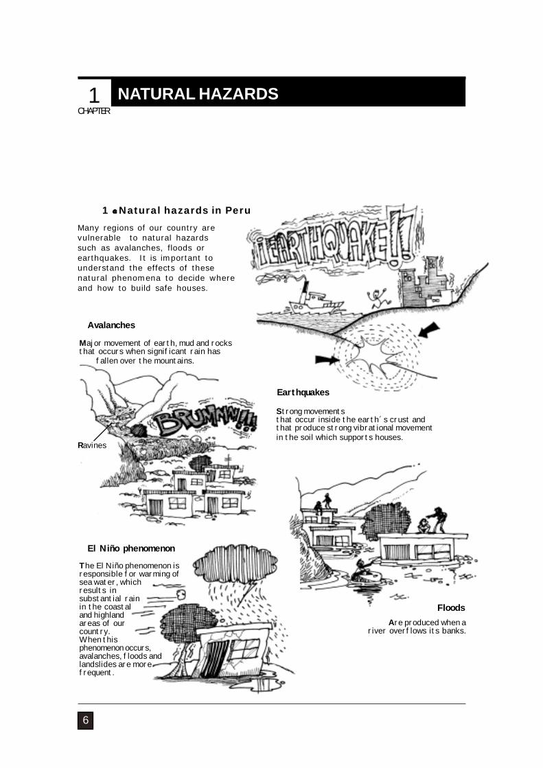
Many regions of our country arevulnerable to natural hazardssuch as avalanches, floods orearthquakes. It is important tounderstand the effects of thesenatural phenomena to decide whereand how to build safe houses.
Avalanches
Major movement of earth, mud and rocksthat occurs when significant rain has
fallen over the mountains.
The El Niño phenomenon isresponsible for warming ofsea water, whichresults insubstantial rainin the coastaland highlandareas of ourcountry.When thisphenomenon occurs,avalanches, floods andlandslides are morefrequent.
FloodsAre produced when a
river overflows its banks.
Strong movementsthat occur inside the earth´s crust andthat produce strong vibrational movementin the soil which supports houses.

NATURAL HAZARDS
Z 1
ECUADOR
BRAZIL
COLOMBIA
Z 2
Z 3
What type of damage can earthquakes produce?
PACIFIC
OCEA
N
7
2 Earthquakes
Z2Z3
Z1 Low seismicityMedium seismicityHigh seismicity
Earthquake risk is not the same in alllocations. That is why the National
Construction Code has divided Peru inthree seismic regions. The region of
greatest seismic risk is the coast.
Earthquakes can produce significant damageto inadequately designed and constructedhouses. For example, parapets can fall,window glass can break or walls can crack.Houses with severe structural problems cancollapse, causing major material loss, seriousinjury to its occupants and even theregrettable loss of lives.
Seismic regionsaccording to the National
Construction Code:
CONSTRUCTION AND MAINTENANCE OF MASONRY HOUSES
1 Adequate locations
8
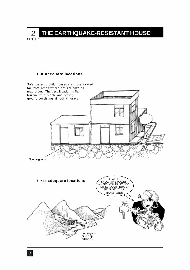
2 Inadequate locations
Stable ground
In canyonsor steephillsides.
THE EARTHQUAKE-RESISTANT HOUSECHAPTER 2
Safe places to build houses are those locatedfar from areas where natural hazardsmay occur. The best location is flatterrain, with stable and strongground consisting of rock or gravel.
I WILLSHOW THE PLACES
WHERE YOU MUST NOTBUILD YOUR HOUSE
BECAUSE IT IS DANGEROUS
NATURAL HAZARDS
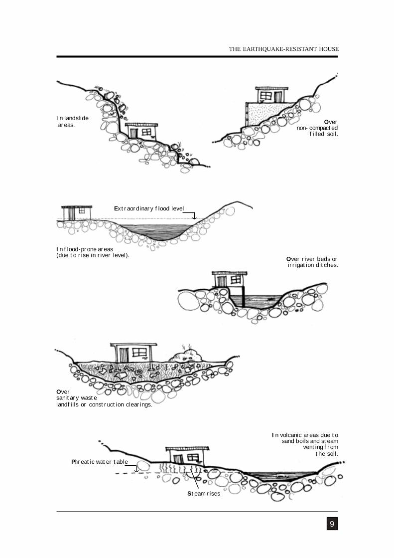
Over river beds orirrigation ditches.
9
In flood-prone areas(due to rise in river level).
Overnon- compacted
filled soil.
Extraordinary flood level
Phreatic water table
THE EARTHQUAKE-RESISTANT HOUSE
In landslide areas.
Oversanitary wastelandfills or construction clearings.
In volcanic areas due to sand boils and steam
venting from the soil.
Steam rises
CONSTRUCTION AND MAINTENANCE OF MASONRY HOUSES
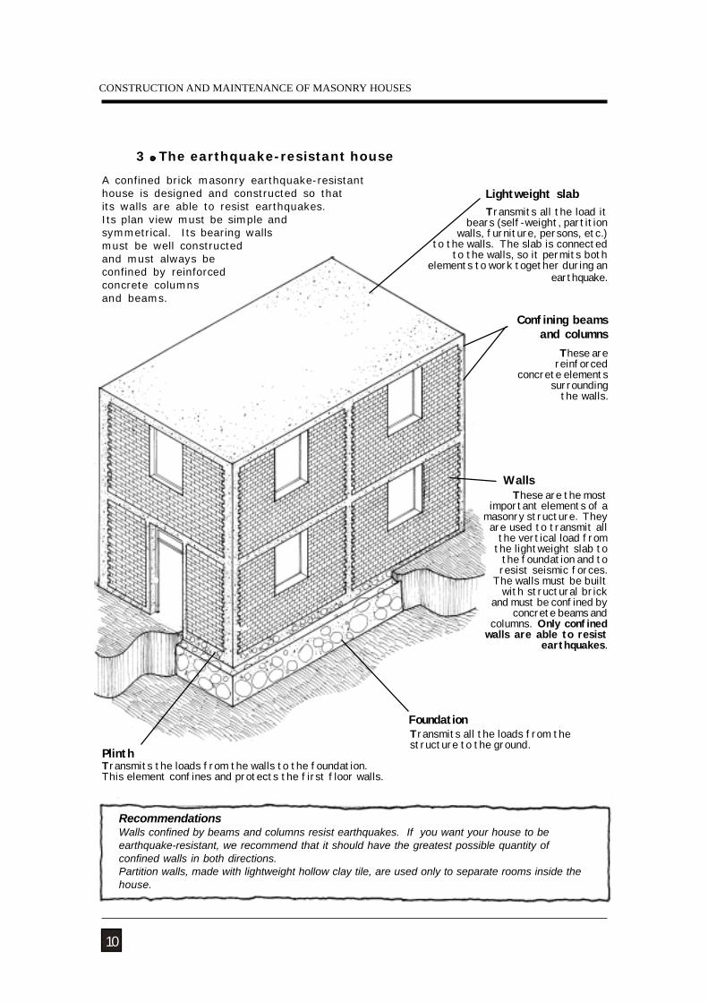
PlinthTransmits the loads from the walls to the foundation.This element confines and protects the first floor walls.
RecommendationsWalls confined by beams and columns resist earthquakes. If you want your house to beearthquake-resistant, we recommend that it should have the greatest possible quantity ofconfined walls in both directions.Partition walls, made with lightweight hollow clay tile, are used only to separate rooms inside thehouse.
3 The earthquake-resistant house
10
Lightweight slab
Confining beams and columns
Transmits all the loads from thestructure to the ground.
These are reinforced
concrete elementssurrounding the walls.
Transmits all the load itbears (self-weight, partition
walls, furniture, persons, etc.) to the walls. The slab is connected
to the walls, so it permits both elements to work together during an
earthquake.
These are the mostimportant elements of a
masonry structure. Theyare used to transmit all
the vertical load from the lightweight slab to
the foundation and toresist seismic forces.
The walls must be builtwith structural brick
and must be confined byconcrete beams and
columns. Only confinedwalls are able to resist
earthquakes.
A confined brick masonry earthquake-resistanthouse is designed and constructed so thatits walls are able to resist earthquakes.Its plan view must be simple andsymmetrical. Its bearing wallsmust be well constructedand must always beconfined by reinforcedconcrete columnsand beams.
Foundation
Walls
NATURAL HAZARDS
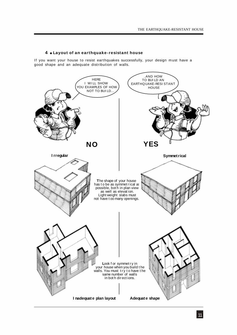
Inadequate plan layout
SymmetricalIrregular
4 Layout of an earthquake-resistant house
Adequate shape
The shape of your house has to be as symmetrical as possible, both in plan view
as well as elevation. Lightweight slabs must
not have too many openings.
NO
11
If you want your house to resist earthquakes successfully, your design must have agood shape and an adequate distribution of walls.
HEREI WILL SHOW
YOU EXAMPLES OF HOWNOT TO BUILD…
...AND HOWTO BUILD AN
EARTHQUAKE-RESISTANT HOUSE
YES
Look for symmetry in your house when you build thewalls. You must try to have the
same number of wallsin both directions.
THE EARTHQUAKE-RESISTANT HOUSE
CONSTRUCTION AND MAINTENANCE OF MASONRY HOUSES
12
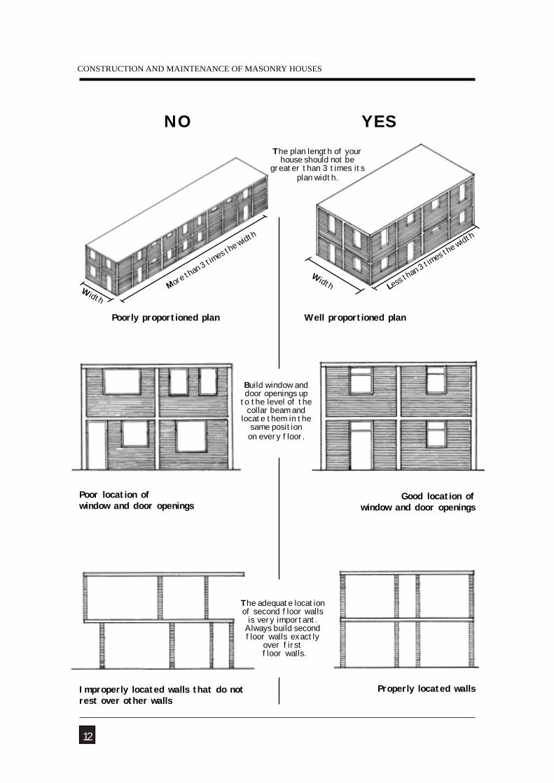
Improperly located walls that do notrest over other walls
More than 3
times t
he width
Width
Poorly proportioned plan
Width Less th
an 3 tim
es the w
idth
Well proportioned plan
NO YES
The plan length of yourhouse should not be
greater than 3 times itsplan width.
Build window anddoor openings up
to the level of thecollar beam and
locate them in thesame positionon every floor.
Poor location ofwindow and door openings
Properly located walls
Good location ofwindow and door openings
The adequate locationof second floor walls
is very important.Always build secondfloor walls exactly
over first floor walls.
NATURAL HAZARDS
13
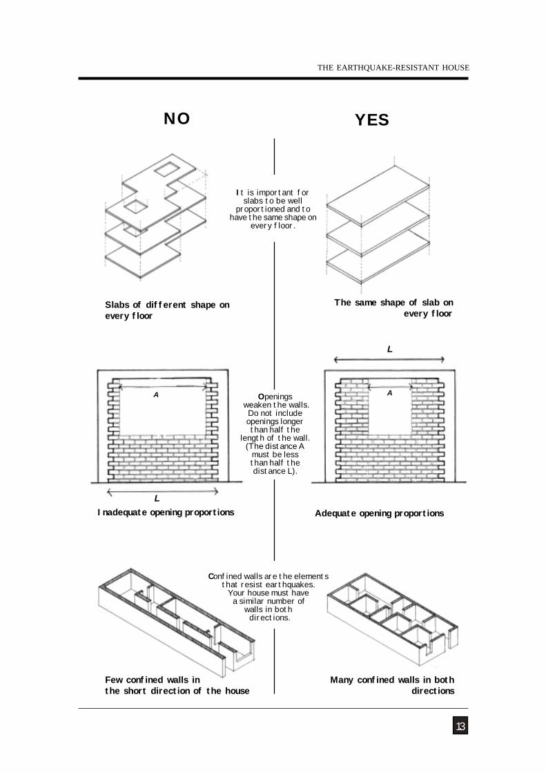
NO YES
Inadequate opening proportions Adequate opening proportions
The same shape of slab on every floor
Slabs of different shape onevery floor
It is important forslabs to be well
proportioned and tohave the same shape on
every floor.
Many confined walls in bothdirections
Few confined walls inthe short direction of the house
A
L
Confined walls are the elementsthat resist earthquakes.
Your house must have a similar number of
walls in both directions.
Openings weaken the walls.
Do not includeopenings longerthan half the
length of the wall.(The distance A
must be lessthan half thedistance L).
A
L
THE EARTHQUAKE-RESISTANT HOUSE
CONSTRUCTION AND MAINTENANCE OF MASONRY HOUSES
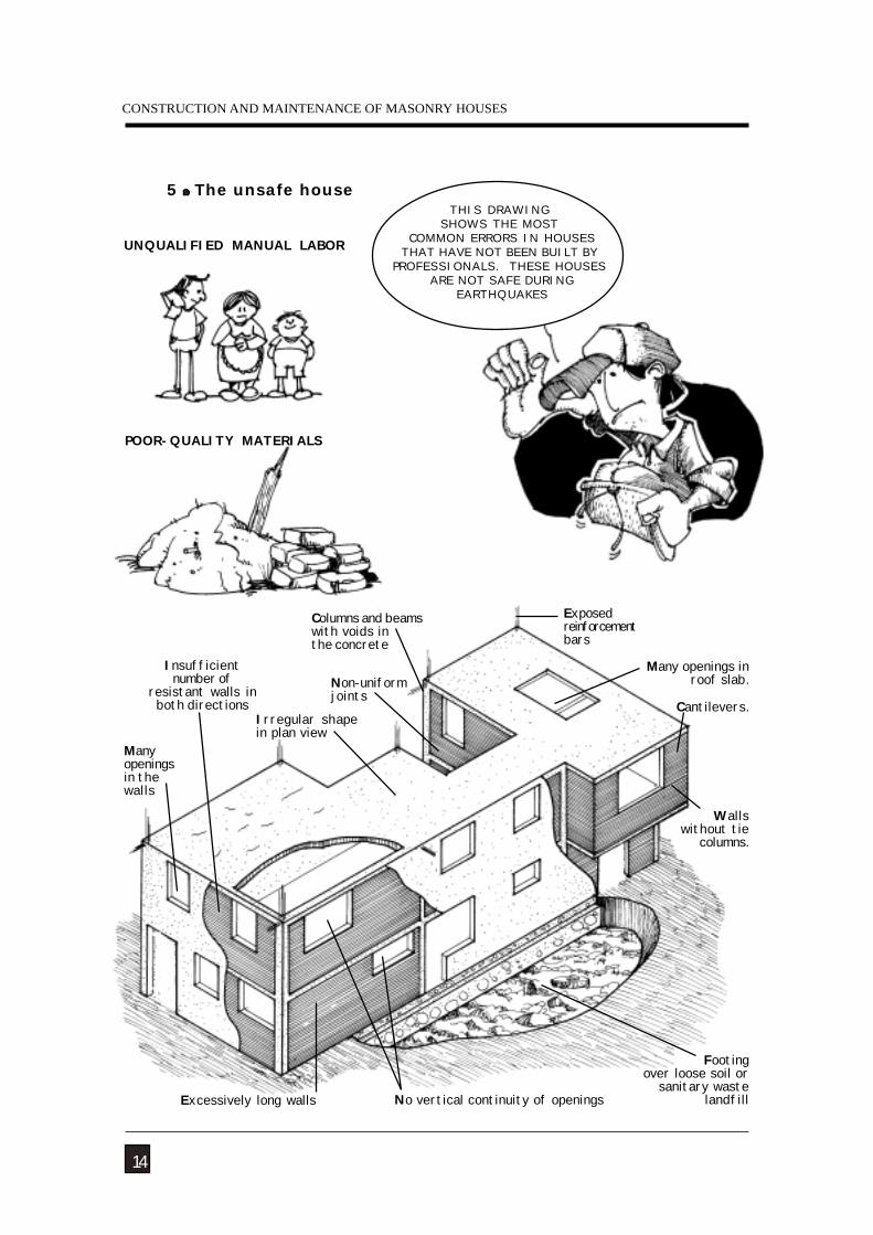
Cantilevers.Irregular shapein plan view
Excessively long walls
Manyopeningsin thewalls
Exposedreinforcementbars
Walls without tie
columns.
Many openings inroof slab.
Insufficientnumber of
resistant walls inboth directions
UNQUALIFIED MANUAL LABOR
POOR-QUALITY MATERIALS
Columns and beamswith voids inthe concrete
Non-uniformjoints
5 The unsafe house
Footingover loose soil or
sanitary wastelandfillNo vertical continuity of openings
14
THIS DRAWINGSHOWS THE MOST
COMMON ERRORS IN HOUSESTHAT HAVE NOT BEEN BUILT BY
PROFESSIONALS. THESE HOUSES ARE NOT SAFE DURING
EARTHQUAKES
NATURAL HAZARDS
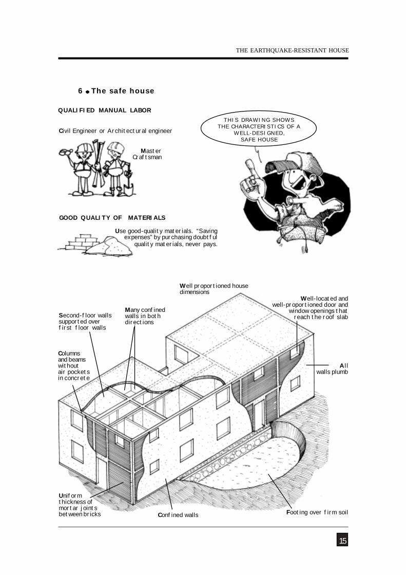
GOOD QUALITY OF MATERIALS
Columnsand beamswithoutair pocketsin concrete
A llwalls plumb
Confined walls
Many confinedwalls in bothdirections
Footing over firm soil
Second-floor wallssupported overfirst floor walls
Well-located and well-proportioned door and
window openings thatreach the roof slab
Uniformthickness ofmortar jointsbetween bricks
MasterCraftsman
Well proportioned housedimensions
Use good-quality materials. “Savingexpenses” by purchasing doubtful
quality materials, never pays.
QUALIFIED MANUAL LABOR
Civil Engineer or Architectural engineer
6 The safe house
15
THE EARTHQUAKE-RESISTANT HOUSE
THIS DRAWING SHOWSTHE CHARACTERISTICS OF A
WELL-DESIGNED,SAFE HOUSE
CONSTRUCTION AND MAINTENANCE OF MASONRY HOUSES
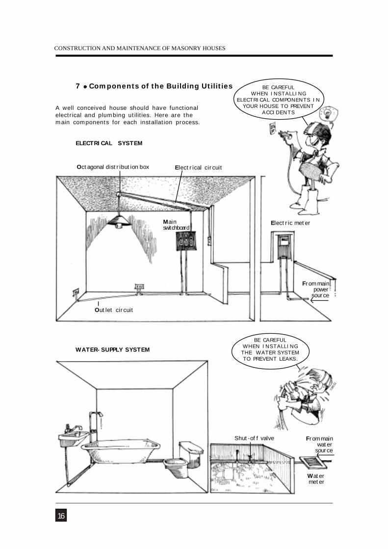
7 Components of the Building Utilities
WATER-SUPPLY SYSTEM
A well conceived house should have functionalelectrical and plumbing utilities. Here are themain components for each installation process.
ELECTRICAL SYSTEM
Outlet circuit
Electrical circuitOctagonal distribution box
Mainswitchboard
Electric meter
Shut-off valve
Water meter
From mainpower
source
From mainwater
source
16
BE CAREFULWHEN INSTALLING
ELECTRICAL COMPONENTS INYOUR HOUSE TO PREVENT
ACCIDENTS
BE CAREFULWHEN INSTALLING
THE WATER SYSTEMTO PREVENT LEAKS.
NATURAL HAZARDS
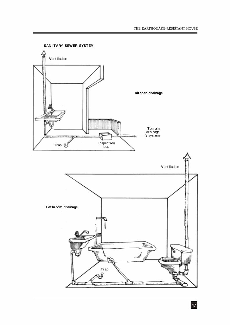
SANITARY SEWER SYSTEM
To maindrainage
system
Trap Inspectionbox
Ventilation
Ventilation
Trap
Kitchen drainage
Bathroom drainage
17
THE EARTHQUAKE-RESISTANT HOUSE
CONSTRUCTION AND MAINTENANCE OF MASONRY HOUSES
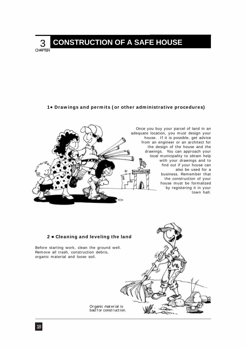
1 Drawings and permits (or other administrative procedures)
18
Organic material isbad for construction.
Before starting work, clean the ground well.Remove all trash, construction debris,organic material and loose soil.
2 Cleaning and leveling the land
Once you buy your parcel of land in anadequate location, you must design your
house. If it is possible, get advicefrom an engineer or an architect for
the design of the house and thedrawings. You can approach your
local municipality to obtain helpwith your drawings and to find out if your house can
also be used for abusiness. Remember that
the construction of yourhouse must be formalized
by registering it in yourtown hall.
CHAPTER
CONSTRUCTION OF A SAFE HOUSE 3
NATURAL HAZARDS
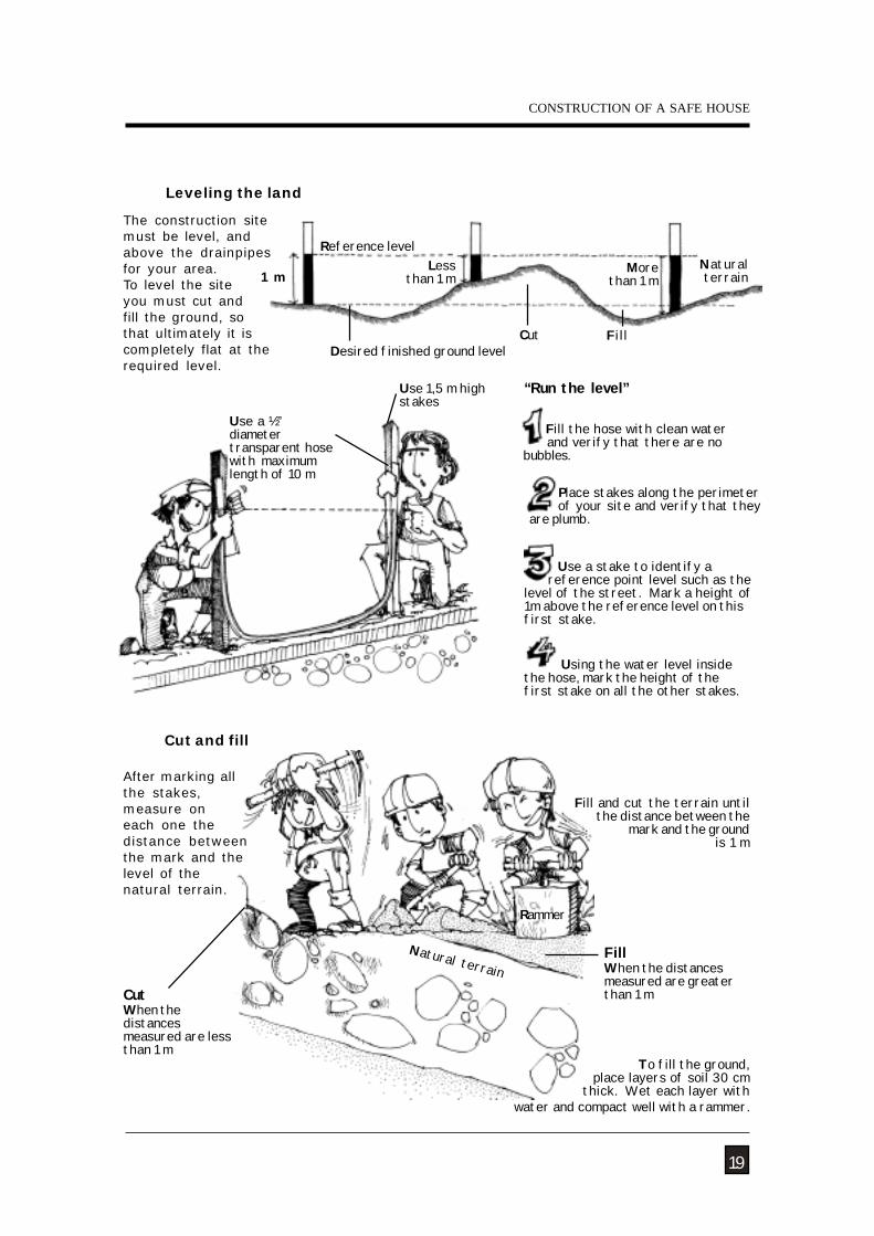
Leveling the land
The construction sitemust be level, andabove the drainpipesfor your area.To level the siteyou must cut andfill the ground, sothat ultimately it iscompletely flat at therequired level.
“Run the level”Use 1,5 m highstakes
Use a ½”diametertransparent hosewith maximumlength of 10 m
Desired finished ground levelFillCut
Reference level
1 mLess
than 1 mMore
than 1 m
19
Naturalterrain
Natural terrain
CutWhen thedistancesmeasured are lessthan 1 m
FillWhen the distancesmeasured are greaterthan 1 m
Cut and fill
To fill the ground, place layers of soil 30 cm
thick. Wet each layer with water and compact well with a rammer.
Rammer
Fill and cut the terrain until the distance between the
mark and the ground is 1 m
After marking allthe stakes,measure oneach one thedistance betweenthe mark and thelevel of thenatural terrain.
Fill the hose with clean water and verify that there are nobubbles.
Place stakes along the perimeter of your site and verify that theyare plumb.
Using the water level insidethe hose, mark the height of thefirst stake on all the other stakes.
CONSTRUCTION OF A SAFE HOUSE
Use a stake to identify a reference point level such as thelevel of the street. Mark a height of1m above the reference level on thisfirst stake.
CONSTRUCTION AND MAINTENANCE OF MASONRY HOUSES
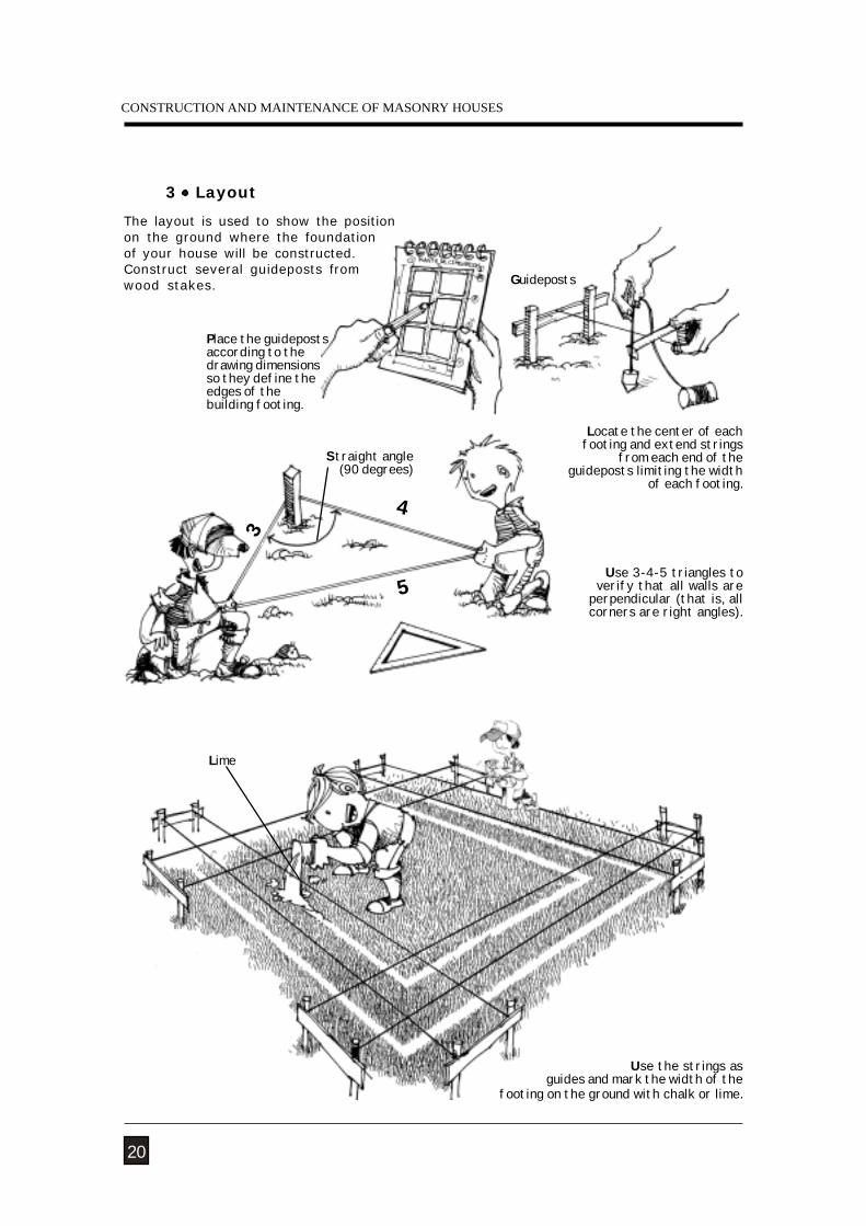
Place the guidepostsaccording to thedrawing dimensionsso they define theedges of thebuilding footing.
Use 3-4-5 triangles toverify that all walls are
perpendicular (that is, allcorners are right angles).
Use the strings asguides and mark the width of the
footing on the ground with chalk or lime.
The layout is used to show the positionon the ground where the foundationof your house will be constructed.Construct several guideposts fromwood stakes. Guideposts
Locate the center of eachfooting and extend strings
from each end of theguideposts limiting the width
of each footing.
5
4
3
3 Layout
20
Straight angle(90 degrees)
Lime
NATURAL HAZARDS
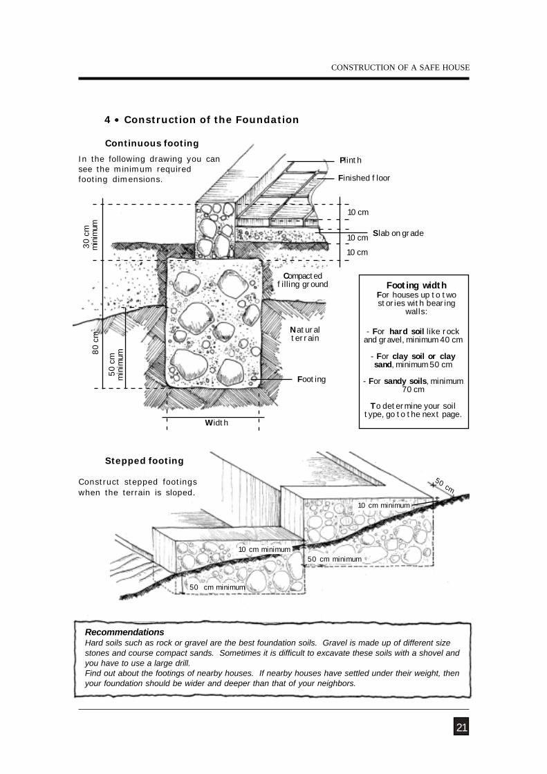
RecommendationsHard soils such as rock or gravel are the best foundation soils. Gravel is made up of different sizestones and course compact sands. Sometimes it is difficult to excavate these soils with a shovel andyou have to use a large drill.Find out about the footings of nearby houses. If nearby houses have settled under their weight, thenyour foundation should be wider and deeper than that of your neighbors.
21
30
cmm
inim
um 8
0 cm
50
cm m
inim
um
Plinth
Footing
Finished floor
Width
10 cm
50 cm
10 cm minimum
50 cm minimum 10 cm minimum
50 cm minimum
Construct stepped footingswhen the terrain is sloped.
Stepped footing
Continuous footing
In the following drawing you cansee the minimum requiredfooting dimensions.
4 Construction of the Foundation
10 cm
10 cm
Slab on grade
Compactedfilling ground
Naturalterrain
Footing widthFor houses up to twostories with bearing
walls:
- For hard soil like rockand gravel, minimum 40 cm
- For clay soil or claysand, minimum 50 cm
- For sandy soils, minimum70 cm
To determine your soiltype, go to the next page.
CONSTRUCTION OF A SAFE HOUSE
CONSTRUCTION AND MAINTENANCE OF MASONRY HOUSES
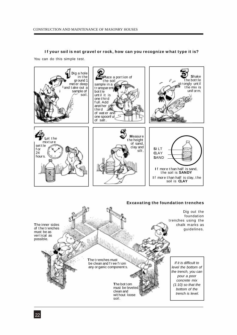
You can do this simple test.
If your soil is not gravel or rock, how can you recognize what type it is?
The inner sidesof the trenchesmust be asvertical aspossible.
The bottommust be leveled,clean andwithout loosesoil.
The trenches must be clean and free from any organic components.
Excavating the foundation trenches
If it is difficult tolevel the bottom ofthe trench, you can
pour a poorconcrete mix
(1:10) so that thebottom of the
trench is level.
Dig a hole in theground 1
meter deep and take out a
sample ofsoil.
If more than half is sand,the soil is SANDY
If more than half is clay, thesoil is CLAY
CLAYSAND
22
Dig out the foundation
trenches using thechalk marks as
guidelines.
Place a portion of the soilsample in atransparentbottleuntil it isone thirdfull. Addanotherthirdof water andone spoonfulof salt.
Shakethe bottle
strongly untilthe mix is
uniform.
Let the mixturesettlefor24hours.
SILT
Measurethe height
of sand,clay and
silt.
NATURAL HAZARDS
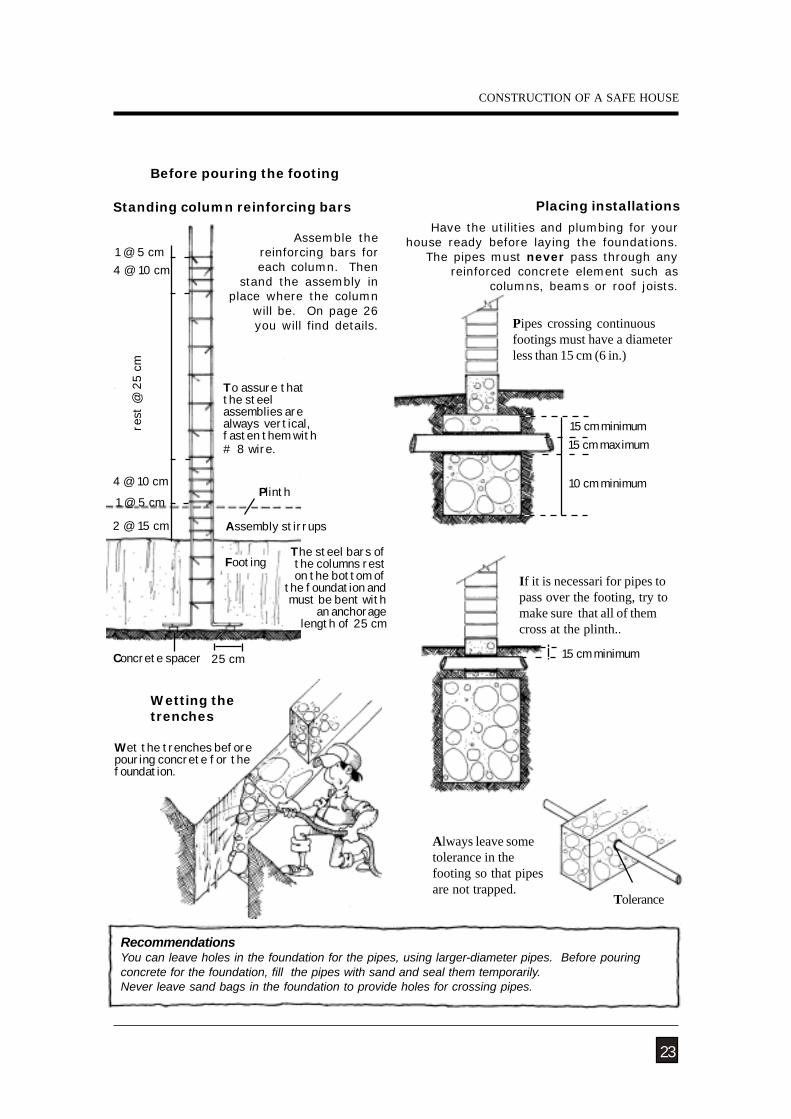
1 @ 5 cm
rest
@ 2
5 cm
1 @ 5 cm4 @ 10 cm
4 @ 10 cm
2 @ 15 cm
Footing
Before pouring the footing
Placing installations
Always leave sometolerance in thefooting so that pipesare not trapped.
Wetting thetrenches
Wet the trenches beforepouring concrete for thefoundation.
RecommendationsYou can leave holes in the foundation for the pipes, using larger-diameter pipes. Before pouringconcrete for the foundation, fill the pipes with sand and seal them temporarily.Never leave sand bags in the foundation to provide holes for crossing pipes.
23
Standing column reinforcing bars
Assemble thereinforcing bars foreach column. Then
stand the assembly inplace where the column
will be. On page 26you will find details.
To assure thatthe steelassemblies arealways vertical,fasten them with# 8 wire.
Plinth
Concrete spacer 25 cm
The steel bars ofthe columns reston the bottom of
the foundation andmust be bent with
an anchoragelength of 25 cm
15 cm minimum15 cm maximum
10 cm minimum
Have the utilities and plumbing for yourhouse ready before laying the foundations.
The pipes must never pass through anyreinforced concrete element such as
columns, beams or roof joists.
Pipes crossing continuousfootings must have a diameterless than 15 cm (6 in.)
Tolerance
15 cm minimum
If it is necessari for pipes topass over the footing, try tomake sure that all of themcross at the plinth..
CONSTRUCTION OF A SAFE HOUSE
Assembly stirrups
CONSTRUCTION AND MAINTENANCE OF MASONRY HOUSES
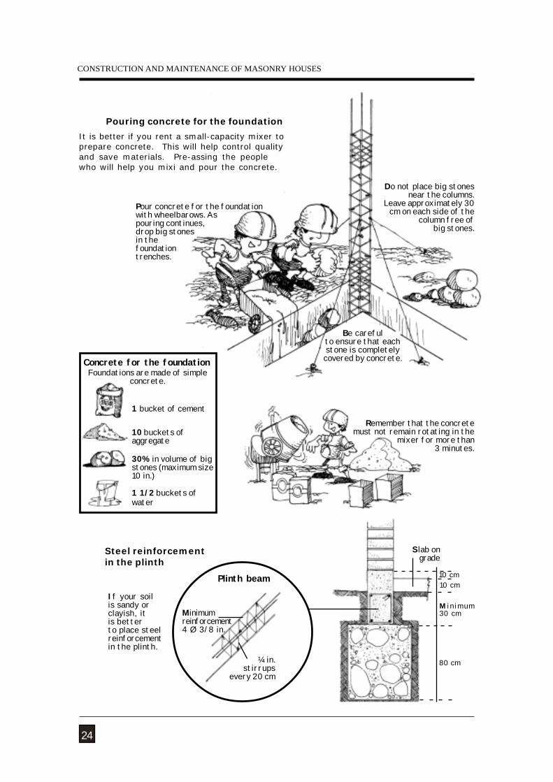
Steel reinforcementin the plinth
Remember that the concretemust not remain rotating in the
mixer for more than 3 minutes.
10 cm
It is better if you rent a small-capacity mixer toprepare concrete. This will help control qualityand save materials. Pre-assing the peoplewho will help you mixi and pour the concrete.
Pouring concrete for the foundation
Pour concrete for the foundationwith wheelbarows. Aspouring continues,drop big stonesin thefoundationtrenches.
Be carefulto ensure that eachstone is completelycovered by concrete.
24
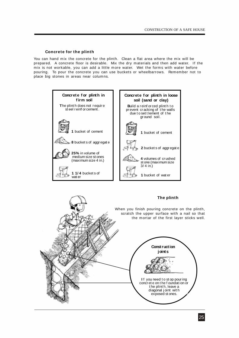
1 1/2 buckets ofwater
1 bucket of cement
Concrete for the foundation
10 buckets ofaggregate
30% in volume of bigstones (maximum size10 in.)
Foundations are made of simpleconcrete.
M in imum30 cm
10 cm
Slab ongrade
If your soilis sandy orclayish, itis betterto place steelreinforcementin the plinth.
Do not place big stonesnear the columns.
Leave approximately 30cm on each side of the
column free ofbig stones.
80 cm
Minimumreinforcement4 Ø 3/8 in.
Plinth beam
¼ in.stirrups
every 20 cm
NATURAL HAZARDS
Concrete for the plinth
Constructionjoints
When you finish pouring concrete on the plinth,scratch the upper surface with a nail so that
the mortar of the first layer sticks well.
You can hand mix the concrete for the plinth. Clean a flat area where the mix will beprepared. A concrete floor is desirable. Mix the dry materials and then add water. If themix is not workable, you can add a little more water. Wet the forms with water beforepouring. To pour the concrete you can use buckets or wheelbarrows. Remember not toplace big stones in areas near columns.
The plinth
25
1 1/4 buckets ofwater
The plinth does not requiresteel reinforcement.
Concrete for plinth in firm soil
8 buckets of aggregate
25% in volume of medium size stones(maximum size 4 in.)
2 buckets of aggregate
1 bucket of water
Concrete for plinth in loosesoil (sand or clay)
Build a reinforced plinth toprevent cracking of the walls
due to settlement of theground soil.
1 bucket of cement
4 volumes of crushedstone (maximum size3/4 in.)
If you need to stop pouringconcrete on the foundation or
the plinth, leave adiagonal joint with
exposed stones.
CONSTRUCTION OF A SAFE HOUSE
1 bucket of cement
CONSTRUCTION AND MAINTENANCE OF MASONRY HOUSES
Reinforcement
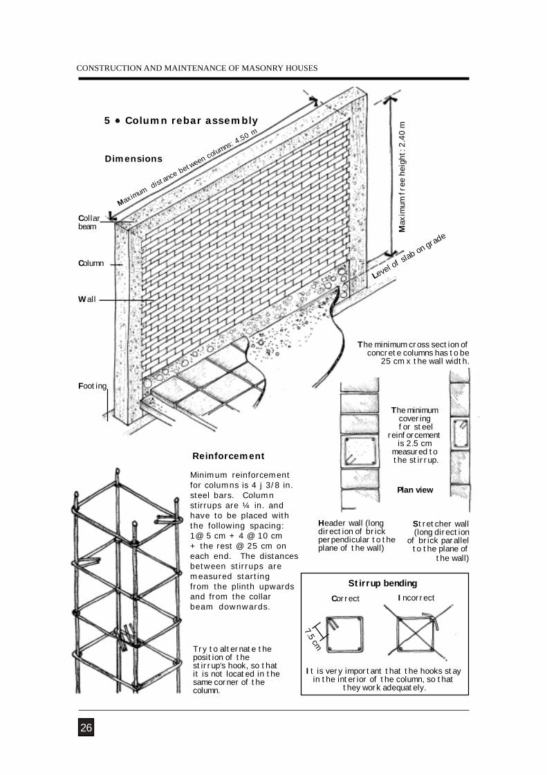
It is very important that the hooks stayin the interior of the column, so that
they work adequately.
Stirrup bendingCorrect Incorrect
Plan view
26
7.5 cm
Max
imum
fre
e he
ight
: 2.4
0 m
Maximum distance between columns: 4
.50 m
Footing
Column
Collarbeam
Wall
5 Column rebar assembly
Dimensions
Level of slab on grad
e
The minimum cross section ofconcrete columns has to be
25 cm x the wall width.
The minimumcovering
for steelreinforcement
is 2.5 cmmeasured to the stirrup.
Stretcher wall(long direction
of brick parallelto the plane of
the wall)
Header wall (longdirection of brickperpendicular to theplane of the wall)
Minimum reinforcementfor columns is 4 j 3/8 in.steel bars. Columnstirrups are ¼ in. andhave to be placed withthe following spacing:1@ 5 cm + 4 @ 10 cm+ the rest @ 25 cm oneach end. The distancesbetween stirrups aremeasured startingfrom the plinth upwardsand from the collarbeam downwards.
Try to alternate theposition of thestirrup‘s hook, so thatit is not located in thesame corner of thecolumn.
NATURAL HAZARDS
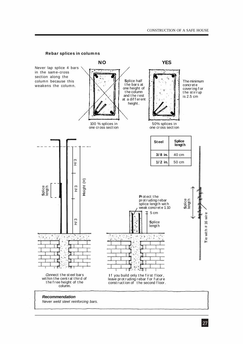
100 % splices inone cross section
Connect the steel barswithin the central third of
the free height of thecolumn.
H/3
Protect theprotruding rebarsplice length withweak concrete 1:10
5 cm
Rebar splices in columns
RecommendationNever weld steel reinforcing bars.
Never lap splice 4 barsin the same-crosssection along thecolumn because thisweakens the column.
NO YES
If you build only the first floor,leave protruding rebar for future construction of the second floor.
Hei
ght (
H)
H/3
Steel Splice length
3/8 in. 40 cm
1/2 in. 50 cm
Splic
ele
ngth
27
50% splices inone cross section
The minimumconcretecovering forthe stirrupis 2.5 cm
Tie
with
#16
wir
e
CONSTRUCTION OF A SAFE HOUSE
Splice half the bars at
one height ofthe column
and the rest at a different
height.
Splic
ele
ngth
Splicelength
H/3
CONSTRUCTION AND MAINTENANCE OF MASONRY HOUSES
28
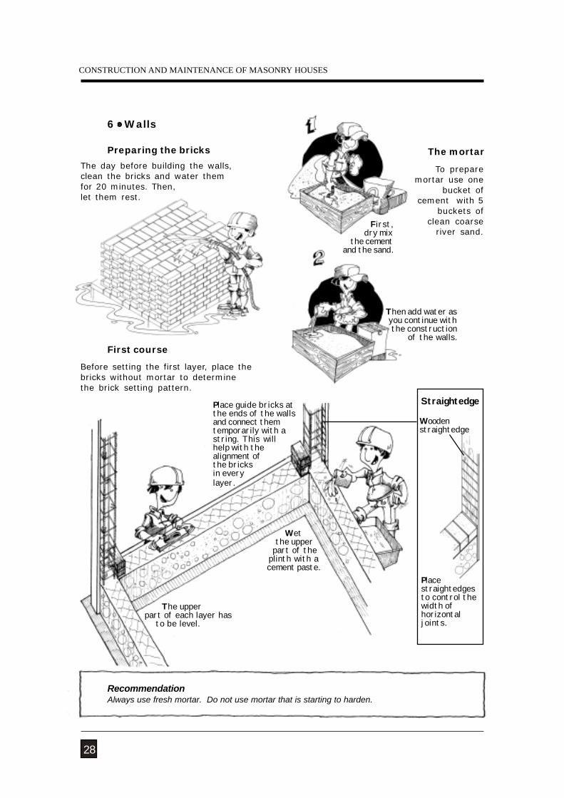
RecommendationAlways use fresh mortar. Do not use mortar that is starting to harden.
The mortar
6 Walls
Preparing the bricks
The day before building the walls,clean the bricks and water themfor 20 minutes. Then,let them rest.
Wet the upper
part of theplinth with acement paste.
Placestraightedgesto control thewidth ofhorizontaljoints.
Place guide bricks atthe ends of the wallsand connect themtemporarily with astring. This willhelp with thealignment ofthe bricksin everylayer.
The upper part of each layer has to be level.
First course
Straightedge
Woodenstraightedge
To preparemortar use one
bucket ofcement with 5
buckets ofclean coarse
river sand.
Then add water asyou continue withthe construction
of the walls.
Before setting the first layer, place thebricks without mortar to determinethe brick setting pattern.
First,dry mix
the cementand the sand.
NATURAL HAZARDS
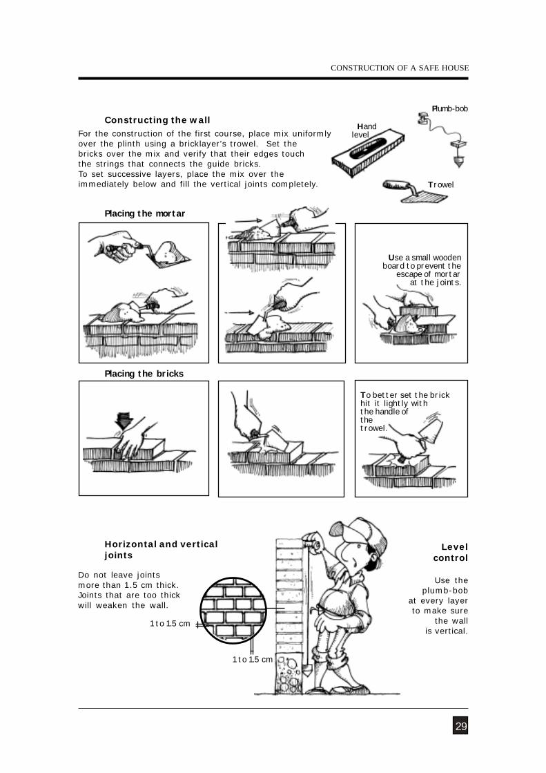
Constructing the wall
Use theplumb-bob
at every layer to make sure
the wall is vertical.
Levelcontrol
Placing the bricks
Placing the mortar
Hand level
Plumb-bob
For the construction of the first course, place mix uniformlyover the plinth using a bricklayer’s trowel. Set thebricks over the mix and verify that their edges touchthe strings that connects the guide bricks.To set successive layers, place the mix over theimmediately below and fill the vertical joints completely.
Horizontal and verticaljoints
To better set the brickhit it lightly withthe handle ofthetrowel.
29
1 to 1.5 cm
1 to 1.5 cm
Do not leave jointsmore than 1.5 cm thick.Joints that are too thickwill weaken the wall.
Trowel
CONSTRUCTION OF A SAFE HOUSE
Use a small woodenboard to prevent the
escape of mortar at the joints.
CONSTRUCTION AND MAINTENANCE OF MASONRY HOUSES
VVVVV
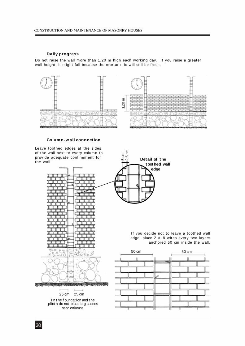
Daily progressDo not raise the wall more than 1.20 m high each working day. If you raise a greaterwall height, it might fall because the mortar mix will still be fresh.
Column-wall connection
If you decide not to leave a toothed walledge, place 2 # 8 wires every two layers
anchored 50 cm inside the wall.
Leave toothed edges at the sidesof the wall next to every column toprovide adequate confinement forthe wall.
50 cm
30
50 cm
In the foundation and theplinth do not place big stones
near columns.
25 cm 25 cm
1.20
m5
cm2.
5 cm
Detail of the toothed wall edge
NATURAL HAZARDS
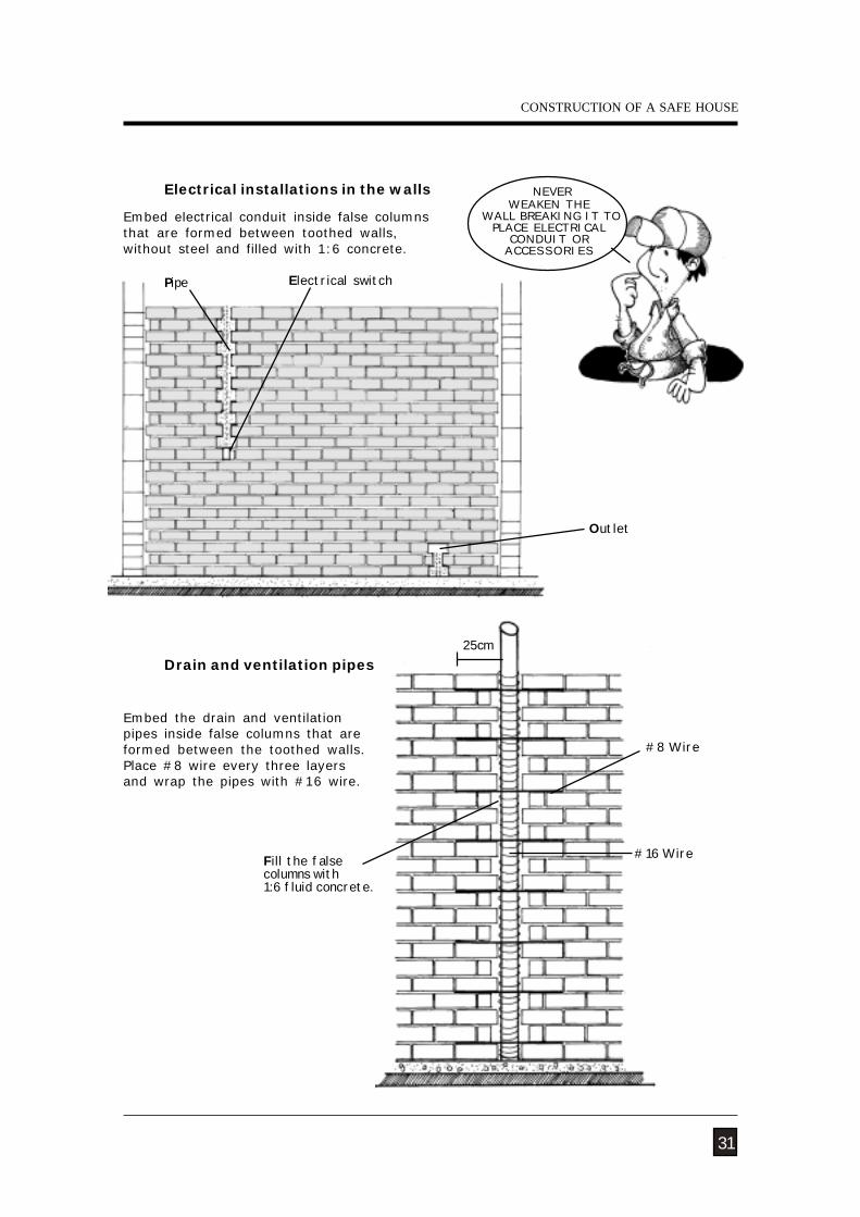
Electrical installations in the walls
#16 Wire
25cm
#8 Wire
Drain and ventilation pipes
Fill the falsecolumns with1:6 fluid concrete.
Outlet
Embed electrical conduit inside false columnsthat are formed between toothed walls,without steel and filled with 1:6 concrete.
Electrical switchPipe
Embed the drain and ventilationpipes inside false columns that areformed between the toothed walls.Place #8 wire every three layersand wrap the pipes with #16 wire.
NEVERWEAKEN THE
WALL BREAKING IT TOPLACE ELECTRICAL
CONDUIT ORACCESSORIES
CONSTRUCTION OF A SAFE HOUSE
31
CONSTRUCTION AND MAINTENANCE OF MASONRY HOUSES
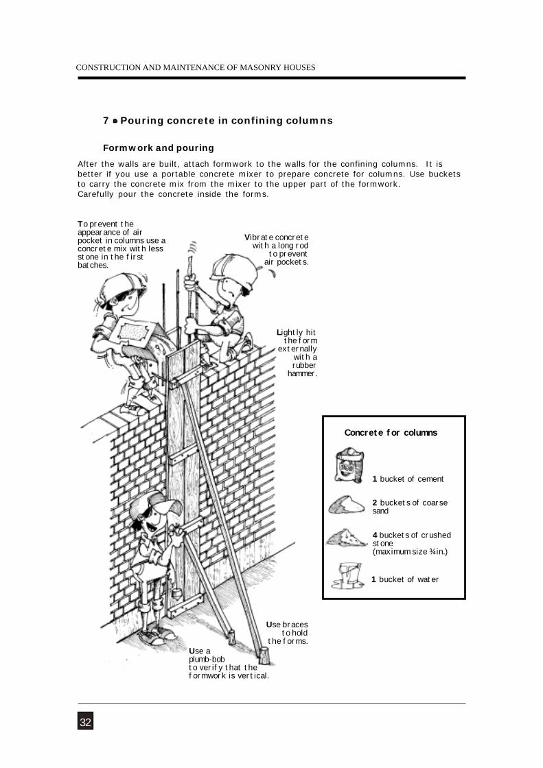
7 Pouring concrete in confining columns
After the walls are built, attach formwork to the walls for the confining columns. It isbetter if you use a portable concrete mixer to prepare concrete for columns. Use bucketsto carry the concrete mix from the mixer to the upper part of the formwork.Carefully pour the concrete inside the forms.
Formwork and pouring
To prevent theappearance of airpocket in columns use aconcrete mix with lessstone in the firstbatches.
Vibrate concretewith a long rod
to preventair pockets.
Lightly hitthe form
externallywith arubber
hammer.
Use aplumb-bobto verify that theformwork is vertical.
Use bracesto hold
the forms.
32
Concrete for columns
2 buckets of coarsesand
4 buckets of crushedstone(maximum size ¾ in.)
1 bucket of water
1 bucket of cement
NATURAL HAZARDS
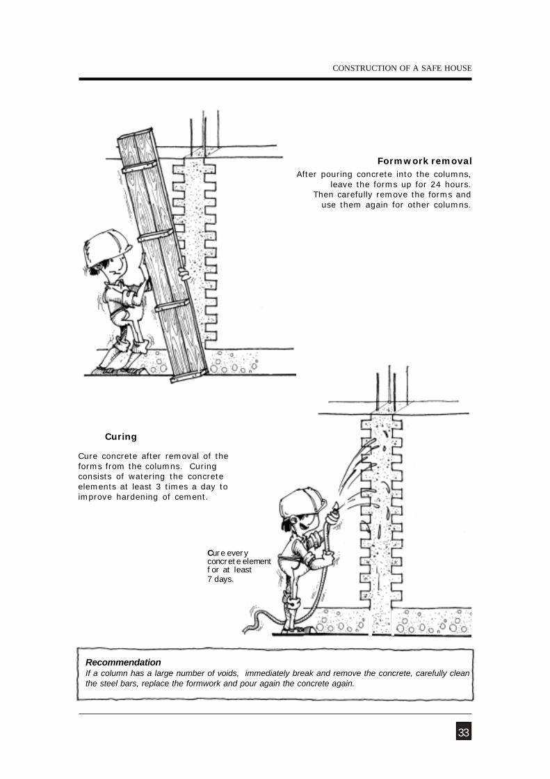
Curing
Formwork removal
RecommendationIf a column has a large number of voids, immediately break and remove the concrete, carefully cleanthe steel bars, replace the formwork and pour again the concrete again.
33
Cure everyconcrete elementfor at least7 days.
Cure concrete after removal of theforms from the columns. Curingconsists of watering the concreteelements at least 3 times a day toimprove hardening of cement.
After pouring concrete into the columns,leave the forms up for 24 hours.
Then carefully remove the forms anduse them again for other columns.
CONSTRUCTION OF A SAFE HOUSE
CONSTRUCTION AND MAINTENANCE OF MASONRY HOUSES
34
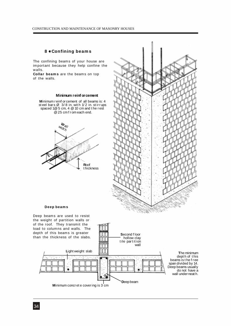
Deep beams
8 Confining beams
The confining beams of your house areimportant because they help confine thewalls.Collar beams are the beams on topof the walls.
Minimum reinforcement of all beams is: 4steel bars Ø 3/8 in. with 1/2 in. stirrupsspaced 1@ 5 cm, 4 @ 10 cm and the rest
@ 25 cm from each end.
Minimum reinforcement
Wallwidth
Roofthickness
Second floorhollow clay
tile partition wall
Lightweight slab
Deep beams are used to resistthe weight of partition walls orof the roof. They transmit theload to columns and walls. Thedepth of this beams is greaterthan the thickness of the slabs.
Minimum concrete covering is 3 cmDeep beam
The minimum depth of this
beams is the freespan divided by 14.
Deep beams usually do not have a
wall underneath.
NATURAL HAZARDS
3 Ø 1/2 in.’
20 cm
3 Ø 3/8 in.’
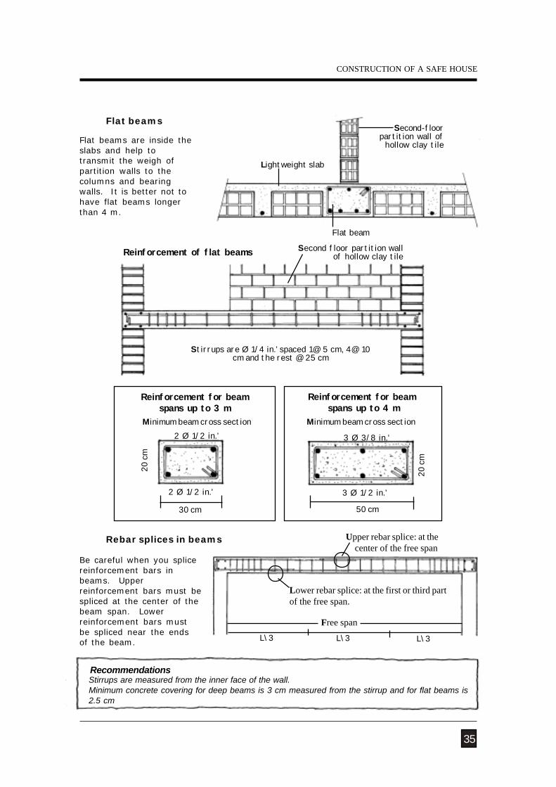
Stirrups are measured from the inner face of the wall.Minimum concrete covering for deep beams is 3 cm measured from the stirrup and for flat beams is2.5 cm
Recommendations
Flat beams
Be careful when you splicereinforcement bars inbeams. Upperreinforcement bars must bespliced at the center of thebeam span. Lowerreinforcement bars mustbe spliced near the endsof the beam.
Rebar splices in beams
Flat beams are inside theslabs and help totransmit the weigh ofpartition walls to thecolumns and bearingwalls. It is better not tohave flat beams longerthan 4 m.
Second-floorpartition wall of
hollow clay tile
Lightweight slab
Second floor partition wallof hollow clay tile
Stirrups are Ø 1/4 in.’ spaced 1@ 5 cm, 4@ 10cm and the rest @ 25 cm
Reinforcement of flat beams
35
Flat beam
Reinforcement for beamspans up to 3 m
30 cm
Reinforcement for beam spans up to 4 m
Minimum beam cross section
50 cm
L\3 L\3 L\3
Free span
Upper rebar splice: at the center of the free span
Lower rebar splice: at the first or third partof the free span.
CONSTRUCTION OF A SAFE HOUSE
Minimum beam cross section
2 Ø 1/2 in.’
20 cm
2 Ø 1/2 in.’
CONSTRUCTION AND MAINTENANCE OF MASONRY HOUSES
Spacers for beams
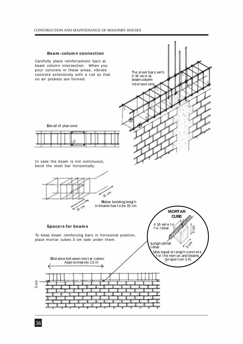
Beam-column connection
Detail of plan view
15 cm
15 cm
>
<
Rebar bending length in beams has to be 15 cm
Carefully place reinforcement bars atbeam column intersection. When youpour concrete in these areas, vibrateconcrete extensively with a rod so thatno air pockets are formed.
In case the beam is not continuous,bend the steel bar horizontally.
To keep beam reinforcing bars in horizontal position,place mortar cubes 3 cm side under them.
36
Tie steel bars with#16 wire atbeam-columnintersections
3 cm
Distance between mortar cubes:Approximately 1.5 m
Use equal strength concretefor the mortar and beams
(proportion 1:4)
MORTARCUBE
3 cm
3 cm
#16 wire tofix rebar
Longitudinalrebar
NATURAL HAZARDS
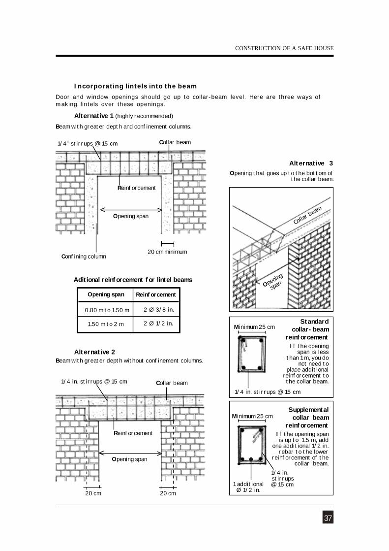
Incorporating lintels into the beam
Alternative 1 (highly recommended)
20 cm 20 cm
Alternative 2
Opening span
Reinforcement
< >
Aditional reinforcement for lintel beams
Door and window openings should go up to collar-beam level. Here are three ways ofmaking lintels over these openings.
If the opening spanis up to 1.5 m, add
one additional 1/2 in.rebar to the lower
reinforcement of the collar beam.
2 Ø 3/8 in.
2 Ø 1/2 in.
Reinforcement
0.80 m to 1.50 m
1.50 m to 2 m
Opening span
Confining column
Collar beam
Opening span
Reinforcement
1/4” stirrups @ 15 cm
< >
Beam with greater depth and confinement columns.
Beam with greater depth without confinement columns.
Collar beam
Opening that goes up to the bottom ofthe collar beam.
Alternative 3
If the openingspan is less
than 1 m, you donot need to
place additionalreinforcement tothe collar beam.
Supplemental collar beam
reinforcement
20 cm minimum
37
Opening
span
Collar beam
Standardcollar-beam
reinforcementMinimum 25 cm
1 additionalØ 1/2 in.
CONSTRUCTION OF A SAFE HOUSE
Minimum 25 cm
1/4 in. stirrups @ 15 cm
1/4 in. stirrups @ 15 cm
1/4 in. stirrups @ 15 cm
CONSTRUCTION AND MAINTENANCE OF MASONRY HOUSES
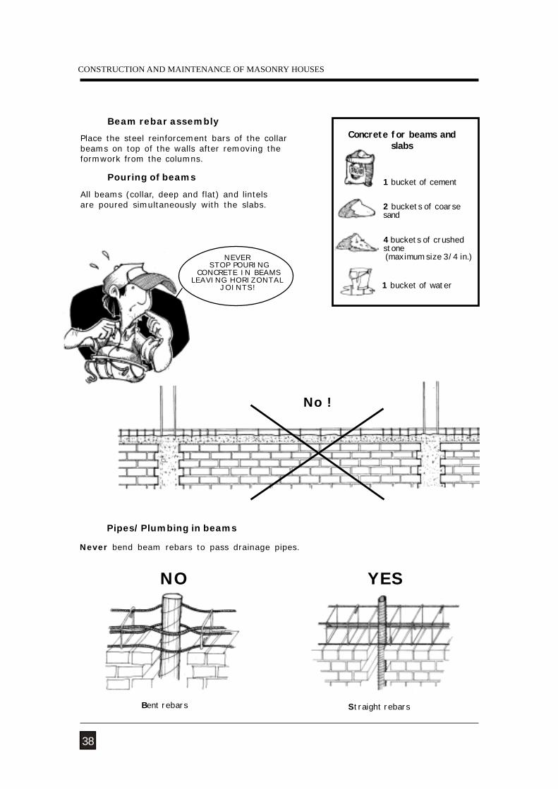
Pouring of beams
No !
Beam rebar assembly
Place the steel reinforcement bars of the collarbeams on top of the walls after removing theformwork from the columns.
All beams (collar, deep and flat) and lintelsare poured simultaneously with the slabs.
38
NEVER STOP POURING
CONCRETE IN BEAMSLEAVING HORIZONTAL
JOINTS!
Concrete for beams andslabs
2 buckets of coarsesand
4 buckets of crushedstone (maximum size 3/4 in.)
1 bucket of water
1 bucket of cement
Pipes/Plumbing in beams
Never bend beam rebars to pass drainage pipes.
NO
Bent rebars
YES
Straight rebars
NATURAL HAZARDS
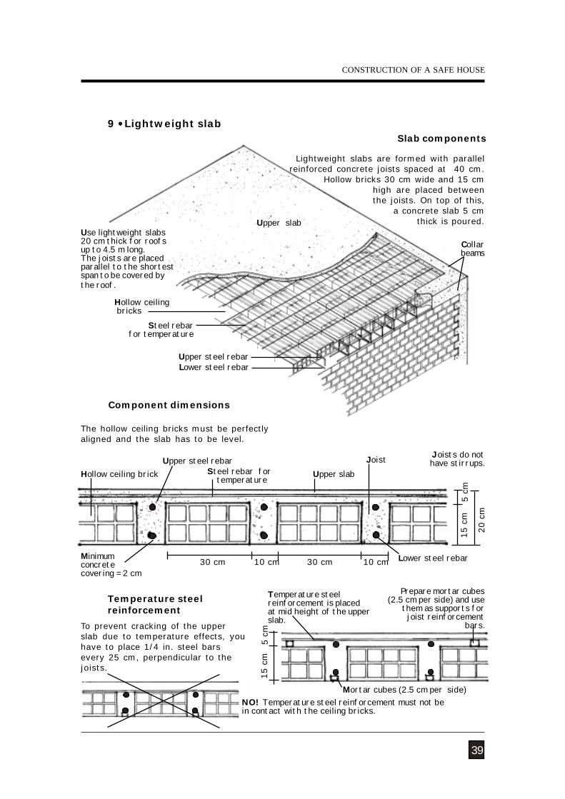
Steel rebar for temperature
NO! Temperature steel reinforcement must not bein contact with the ceiling bricks.
Slab components
Lightweight slabs are formed with parallelreinforced concrete joists spaced at 40 cm.
Hollow bricks 30 cm wide and 15 cmhigh are placed betweenthe joists. On top of this,
a concrete slab 5 cm thick is poured.
Use lightweight slabs20 cm thick for roofsup to 4.5 m long.The joists are placedparallel to the shortestspan to be covered bythe roof.
Component dimensions
The hollow ceiling bricks must be perfectlyaligned and the slab has to be level.
Temperature steelreinforcement
To prevent cracking of the upperslab due to temperature effects, youhave to place 1/4 in. steel barsevery 25 cm, perpendicular to thejoists.
Prepare mortar cubes (2.5 cm per side) and use
them as supports forjoist reinforcement
bars.
Temperature steelreinforcement is placedat mid height of the upperslab.
Collar beams
Lower steel rebar
Upper slab
Joists do nothave stirrups.
9 Lightweight slab
39
15 c
m5 c
m
Mortar cubes (2.5 cm per side)
Hollow ceiling brickJoistUpper steel rebar
Lower steel rebar
Upper slab
30 cm10 cm30 cm 10 cm
5 c
m
20 c
m
15 c
m
Minimumconcretecovering = 2 cm
CONSTRUCTION OF A SAFE HOUSE
Hollow ceiling bricks
Upper steel rebar
Steel rebar for temperature
CONSTRUCTION AND MAINTENANCE OF MASONRY HOUSES
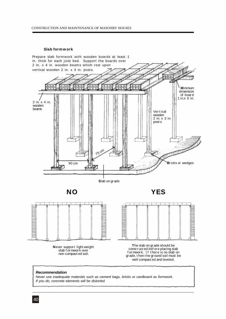
Slab formwork
Never support lightweightslab formwork overnon-compacted soil.
The slab on grade should beconstructed before placing slab
formwork. If there is no slab ongrade, then the ground soil must be
well compacted and leveled.
RecommendationNever use inadequate materials such as cement bags, bricks or cardboard as formwork.If you do, concrete elements will be distorted.
NO YES
Prepare slab formwork with wooden boards at least 1in. thick for each joist bed. Support the boards over2 in. x 4 in. wooden beams which rest uponvertical wooden 2 in. x 3 in. posts.
75 cm
Slab on grade
Verticalwooden2 in. x 3 in.posts
Bricks or wedges
Minimumdimension of board
1 in.x 6 in.2 in. x 4 in.woodenbeams
90 cm
40
NATURAL HAZARDS
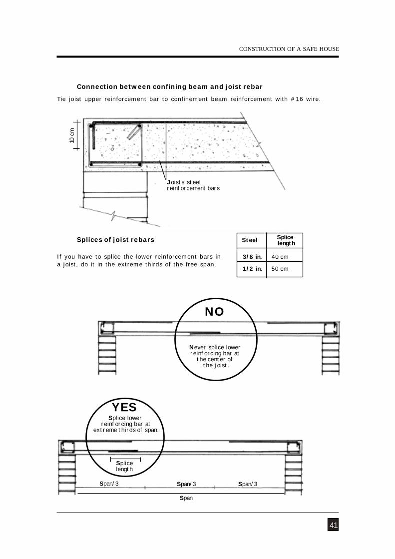
Connection between confining beam and joist rebar
Splices of joist rebars
If you have to splice the lower reinforcement bars ina joist, do it in the extreme thirds of the free span.
Tie joist upper reinforcement bar to confinement beam reinforcement with #16 wire.
10 cm
41
Joists steelreinforcement bars
Steel Splice length
3/8 in. 40 cm
1/2 in. 50 cm
Splice lower reinforcing bar at
extreme thirds of span.
YES
Splicelength
Never splice lowerreinforcing bar at
the center of the joist.
NO
CONSTRUCTION OF A SAFE HOUSE
Span/3 Span/3 Span/3
Span
CONSTRUCTION AND MAINTENANCE OF MASONRY HOUSES
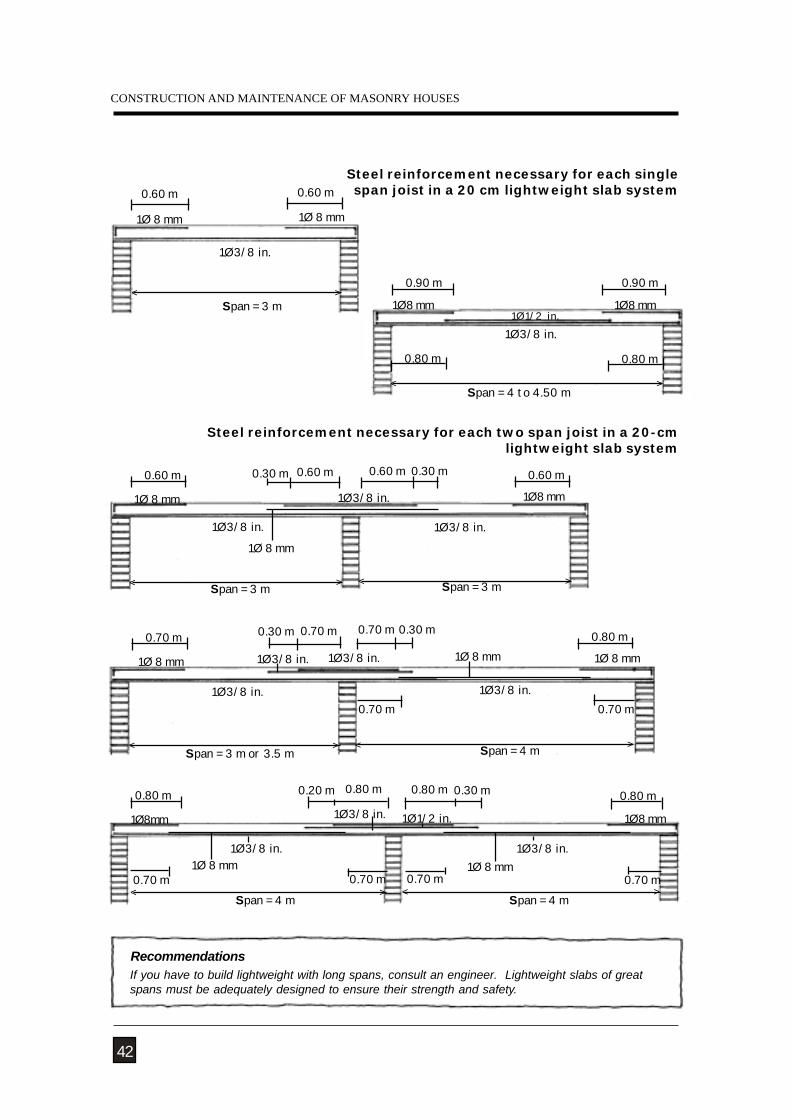
1Ø8 mm
0.60 m 0.60 m0.60 m 0.60 m
1Ø3/8 in.
1Ø 8 mm 1Ø3/8 in.
< >
1Ø3/8 in.
< >Span = 3 m Span = 3 m
0.30 m 0.30 m
1Ø 8 mm
RecommendationsIf you have to build lightweight with long spans, consult an engineer. Lightweight slabs of greatspans must be adequately designed to ensure their strength and safety.
Steel reinforcement necessary for each singlespan joist in a 20 cm lightweight slab system
Steel reinforcement necessary for each two span joist in a 20-cm lightweight slab system
42
1Ø 8 mm
Span = 3 m
1Ø3/8 in.
1Ø 8 mm
0.60 m0.60 m
< >
1Ø3/8 in.
1Ø3/8 in.
0.80 m 0.80 m
1Ø8 mm1Ø8mm
1Ø3/8 in.
0.80 m 0.80 m
< >Span = 4 m
< >Span = 4 m
1Ø1/2 in.
0.20 m 0.30 m
1Ø 8 mm0.70 m0.70 m 0.70 m 0.70 m
1Ø 8 mm
< >
0.90 m
1Ø8 mm 1Ø8 mm1Ø1/2 in.
1Ø3/8 in.
0.90 m
Span = 4 to 4.50 m
0.80 m 0.80 m
1Ø3/8 in.0.70 m 0.70 m 0.70 m 0.80 m
1Ø3/8 in.
1Ø 8 mm1Ø 8 mm 1Ø3/8 in.
1Ø3/8 in.
< >Span = 3 m or 3.5 m
< >Span = 4 m
0.30 m 0.30 m
1Ø 8 mm
0.70 m 0.70 m
NATURAL HAZARDS
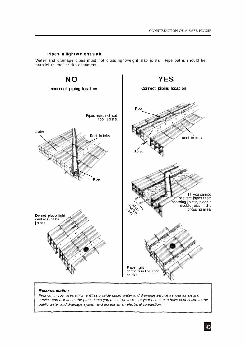
Pipes in lightweight slab
RecomendationFind out in your area which entities provide public water and drainage service as well as electricservice and ask about the procedures you must follow so that your house can have connection to thepublic water and drainage system and access to an electrical connection.
Water and drainage pipes must not cross lightweight slab joists. Pipe paths should beparallel to roof bricks alignment.
43
Pipes must not cutroof joists.
NOIncorrect piping location
Pipe
Roof bricksJoist
Do not place lightcenters in thejoists.
Place lightcenters in the roofbricks.
Correct piping location
YES
Joist
20 cm
Double
joist
If you cannot prevent pipes from
crossing joists, place adouble joist in the
crossing area.
CONSTRUCTION OF A SAFE HOUSE
Pipe
Roof bricks
CONSTRUCTION AND MAINTENANCE OF MASONRY HOUSES
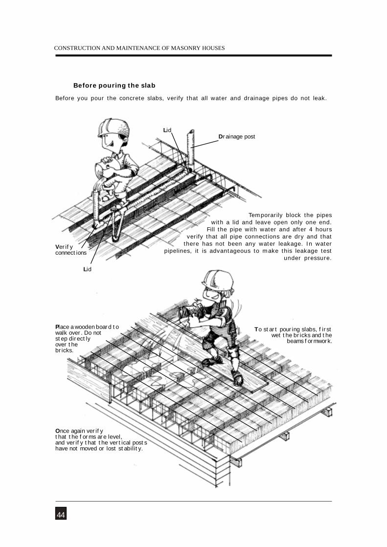
Before pouring the slab
To start pouring slabs, firstwet the bricks and the
beams formwork.
Once again verifythat the forms are level,and verify that the vertical postshave not moved or lost stability.
44
Drainage post
Verifyconnections
Lid
Lid
Temporarily block the pipes with a lid and leave open only one end.
Fill the pipe with water and after 4 hours verify that all pipe connections are dry and that
there has not been any water leakage. In water pipelines, it is advantageous to make this leakage test
under pressure.
Before you pour the concrete slabs, verify that all water and drainage pipes do not leak.
Place a wooden board towalk over. Do notstep directlyover thebricks.
NATURAL HAZARDS
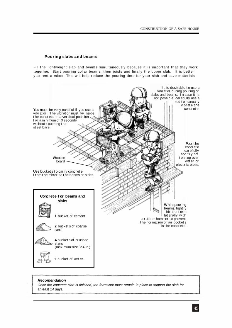
You must be very careful if you use avibrator. The vibrator must be insidethe concrete in a vertical positionfor a minimum of 3 secondswithout touching thesteel bars.
While pouring beams, lightly hit the form
laterally with a rubber hammer to preventthe formation of air pockets
in the concrete.
Fill the lightweight slab and beams simultaneously because it is important that they worktogether. Start pouring collar beams, then joists and finally the upper slab. It is betteryou rent a mixer. This will help reduce the pouring time for your slab and save materials.
Pouring slabs and beams
It is desirable to use avibrator during pouring of
slabs and beams. In case it is not possible, carefully use a
rod to manually vibrate the
concrete.
Use buckets to carry concretefrom the mixer to the beams or slabs.
RecomendationOnce the concrete slab is finished, the formwork must remain in place to support the slab forat least 14 days.
45
Pour theconcretecarefully
and try notto step over
water orelectric pipes.
Woodenboard
CONSTRUCTION OF A SAFE HOUSE
Concrete for beams andslabs
2 buckets of coarsesand
4 buckets of crushedstone(maximum size 3/4 in.)
1 bucket of water
1 bucket of cement
CONSTRUCTION AND MAINTENANCE OF MASONRY HOUSES
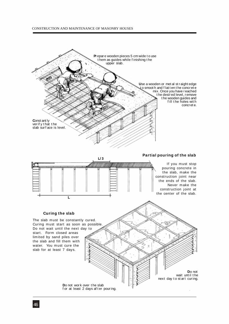
Curing the slab
Do not work over the slabfor at least 2 days after pouring.
The slab must be constantly cured.Curing must start as soon as possible.Do not wait until the next day tostart. Form closed areaslimited by sand piles overthe slab and fill them withwater. You must cure theslab for at least 7 days.
46
Prepare wooden pieces 5 cm wide to use them as guides while finishing the upper slab.
Use a wooden or metal straightedge to smooth and flatten the concrete
mix. Once you have reached the desired level, remove
the wooden guides and fill the holes with
concrete.
Constantlyverify that theslab surface is level.
If you must stop pouring concrete inthe slab, make the
construction joint nearthe ends of the slab.
Never make theconstruction joint at
the center of the slab.
Do not wait until the
next day to start curing.
L/3
L
Partial pouring of the slab
NATURAL HAZARDS
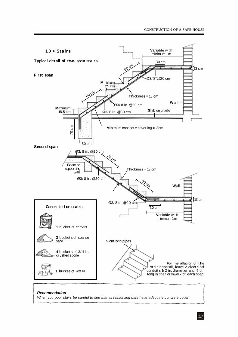
RecomendationWhen you pour stairs be careful to see that all reinforcing bars have adequate concrete cover.
For installation of the stair handrail, leave 2 electrical
conduits 1/2 in. diameter and 5 cm long in the formwork of each step.
5 cm long pipes
Second span50 cm
Ø3/8 in. @30 cm
70 cm
60 cm
Ø3/8 in. @20 cm
60 cm
Ø3/8”@20 cmMinimum
25 cm
Wall
Slab on grade
30 cm
Maximum18.5 cm
13 cm
Typical detail of two-span stairs
First span
Ø3/8 in. @20 cm60 cm
60 cmØ3/8 in. @30 cm
Ø3/8 in. @20 cm30 cm
Wall
13 cm
10 Stairs Variable withminimum 1 m
Thickness = 13 cm
Variable withminimum 1 m
Thickness = 13 cm
47
Beam orsupporting
wall
Minimum concrete covering = 2cm
CONSTRUCTION OF A SAFE HOUSE
Concrete for stairs
2 buckets of coarsesand
4 buckets of 3/4 in.crushed stone
1 bucket of water
1 bucket of cement
CONSTRUCTION AND MAINTENANCE OF MASONRY HOUSES
This chapter contains recommendationsfor the maintenance and solution of someproblems typical brick houses. If theproblems or defects of your house aremore serious, such as foundationsettlement or severe cracking of walls orconcrete elements, we suggest that youconsult an engineer to solve them.
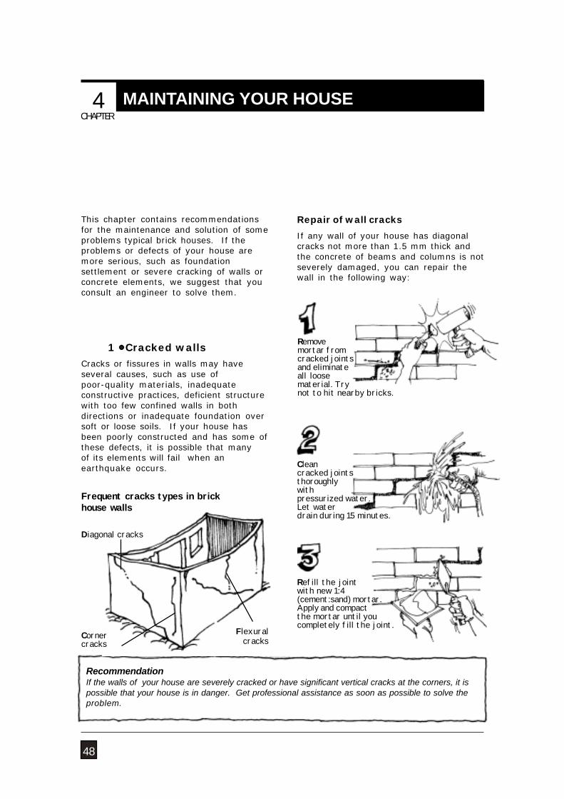
Cracks or fissures in walls may haveseveral causes, such as use ofpoor-quality materials, inadequateconstructive practices, deficient structurewith too few confined walls in bothdirections or inadequate foundation oversoft or loose soils. If your house hasbeen poorly constructed and has some ofthese defects, it is possible that manyof its elements will fail when anearthquake occurs.
Frequent cracks types in brickhouse walls
Flexuralcracks
Diagonal cracks
Cornercracks
RecommendationIf the walls of your house are severely cracked or have significant vertical cracks at the corners, it ispossible that your house is in danger. Get professional assistance as soon as possible to solve theproblem.
Repair of wall cracks
If any wall of your house has diagonalcracks not more than 1.5 mm thick andthe concrete of beams and columns is notseverely damaged, you can repair thewall in the following way:
Cleancracked jointsthoroughlywithpressurized water.Let waterdrain during 15 minutes.
Refill the jointwith new 1:4(cement:sand) mortar.Apply and compactthe mortar until youcompletely fill the joint.
1 Cracked walls
48
CAPITULO
CHAPTER
MAINTAINING YOUR HOUSE 4
Removemortar fromcracked jointsand eliminateall loosematerial. Trynot to hit nearby bricks.
NATURAL HAZARDS
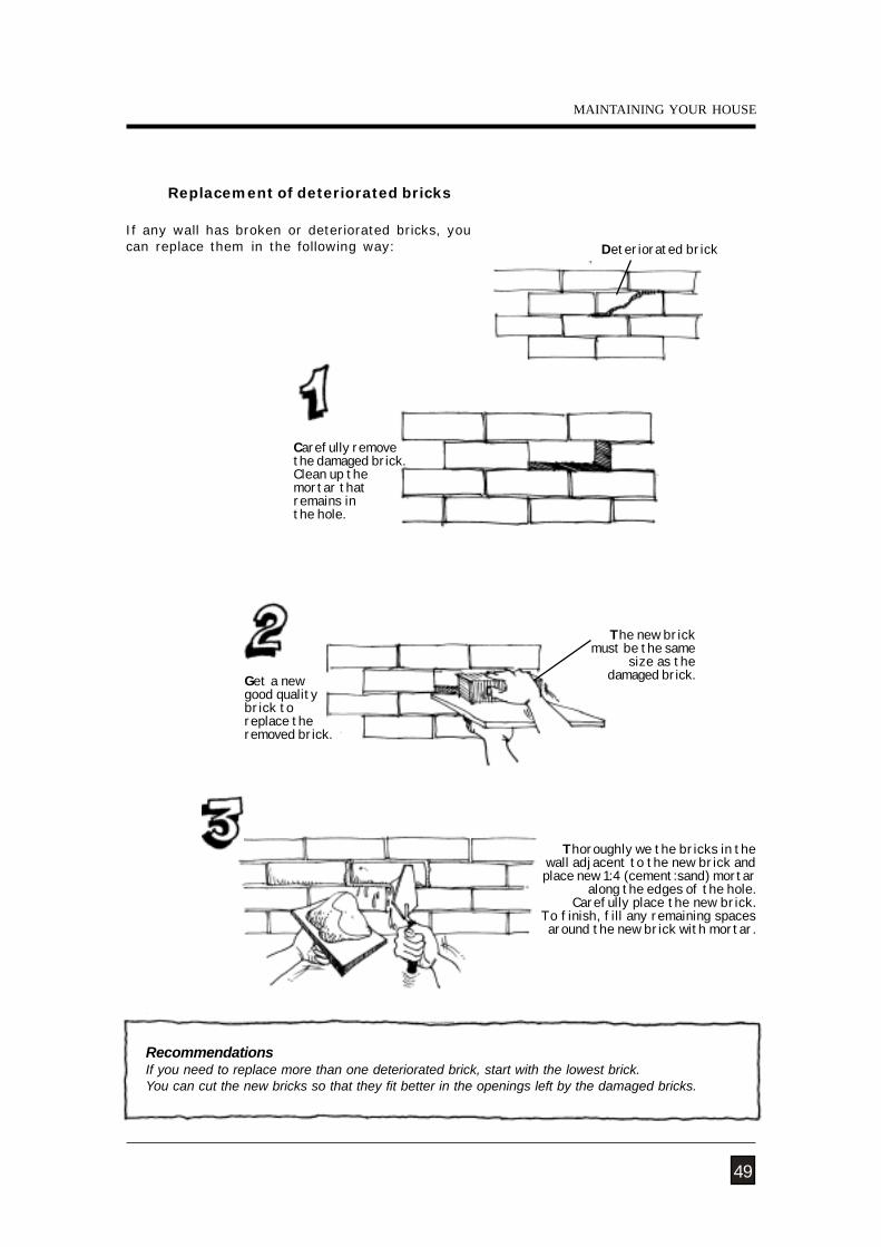
If any wall has broken or deteriorated bricks, youcan replace them in the following way:
Replacement of deteriorated bricks
RecommendationsIf you need to replace more than one deteriorated brick, start with the lowest brick.You can cut the new bricks so that they fit better in the openings left by the damaged bricks.
Thoroughly we the bricks in thewall adjacent to the new brick andplace new 1:4 (cement:sand) mortar
along the edges of the hole. Carefully place the new brick.
To finish, fill any remaining spacesaround the new brick with mortar.
Carefully removethe damaged brick.Clean up themortar thatremains inthe hole.
Deteriorated brick
Get a newgood qualitybrick toreplace theremoved brick.
The new brickmust be the same
size as thedamaged brick.
49
MAINTAINING YOUR HOUSE
CONSTRUCTION AND MAINTENANCE OF MASONRY HOUSES
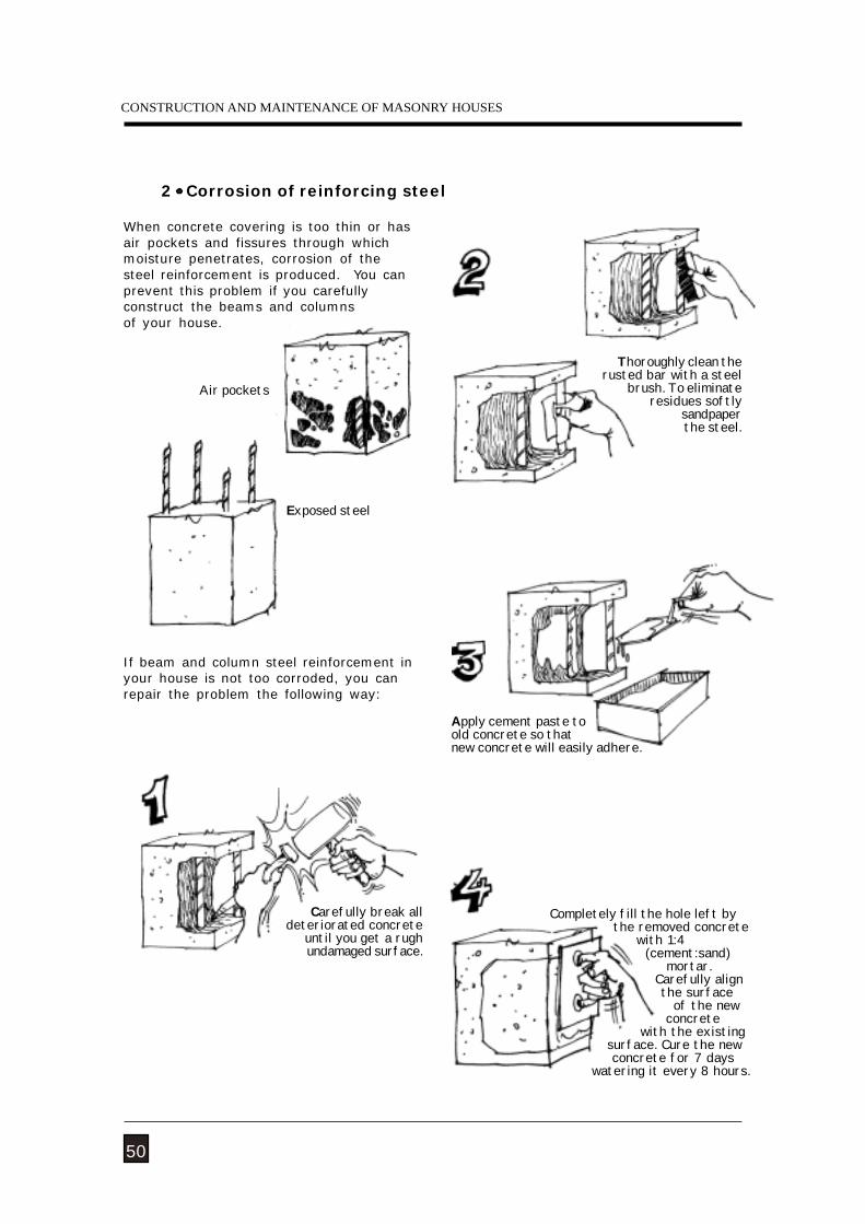
2 Corrosion of reinforcing steel
Completely fill the hole left by the removed concrete with 1:4 (cement:sand) mortar. Carefully align the surface of the new concrete with the existing surface. Cure the new concrete for 7 days watering it every 8 hours.
Thoroughly clean therusted bar with a steel
brush. To eliminate residues softly
sandpaperthe steel.
Carefully break all deteriorated concrete
until you get a rugh undamaged surface.
Exposed steel
Air pockets
50
If beam and column steel reinforcement inyour house is not too corroded, you canrepair the problem the following way:
Apply cement paste toold concrete so thatnew concrete will easily adhere.
When concrete covering is too thin or hasair pockets and fissures through whichmoisture penetrates, corrosion of thesteel reinforcement is produced. You canprevent this problem if you carefullyconstruct the beams and columnsof your house.
NATURAL HAZARDS
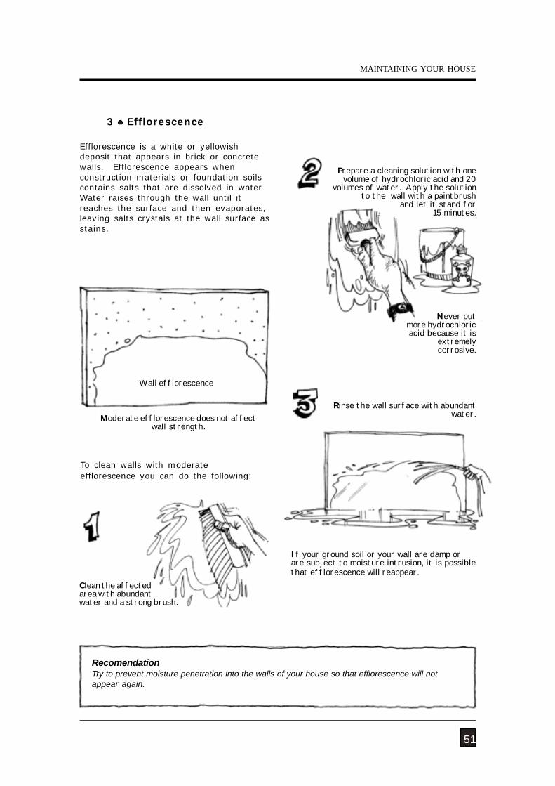
RecomendationTry to prevent moisture penetration into the walls of your house so that efflorescence will notappear again.
3 Efflorescence
Wall efflorescence
Efflorescence is a white or yellowishdeposit that appears in brick or concretewalls. Efflorescence appears whenconstruction materials or foundation soilscontains salts that are dissolved in water.Water raises through the wall until itreaches the surface and then evaporates,leaving salts crystals at the wall surface asstains.
To clean walls with moderateefflorescence you can do the following:
Moderate efflorescence does not affectwall strength.
Rinse the wall surface with abundant water.
Clean the affectedarea with abundantwater and a strong brush.
Prepare a cleaning solution with onevolume of hydrochloric acid and 20
volumes of water. Apply the solutionto the wall with a paintbrush
and let it stand for 15 minutes.
51
Never put more hydrochloricacid because it is
extremely corrosive.
If your ground soil or your wall are damp orare subject to moisture intrusion, it is possiblethat efflorescence will reappear.
MAINTAINING YOUR HOUSE
CONSTRUCTION AND MAINTENANCE OF MASONRY HOUSES
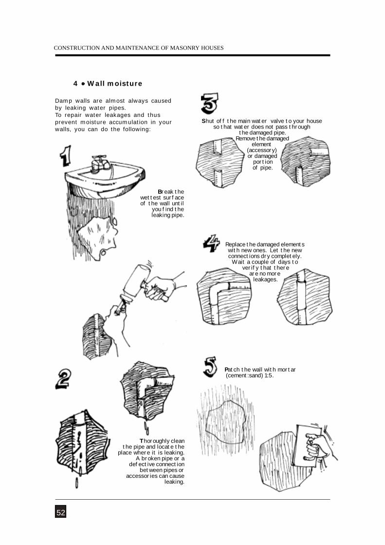
4 Wall moisture
Damp walls are almost always causedby leaking water pipes.To repair water leakages and thusprevent moisture accumulation in yourwalls, you can do the following:
Patch the wall with mortar (cement:sand) 1:5.
Thoroughly clean the pipe and locate the
place where it is leaking.A broken pipe or a
defective connectionbetween pipes or
accessories can causeleaking.
Replace the damaged elementswith new ones. Let the newconnections dry completely.
Wait a couple of days to verify that there
are no more leakages.
52
Break thewettest surfaceof the wall until
you find theleaking pipe.
Shut off the main water valve to your houseso that water does not pass through
the damaged pipe. Remove the damaged
element(accessory) or damaged
portion of pipe.
NATURAL HAZARDS
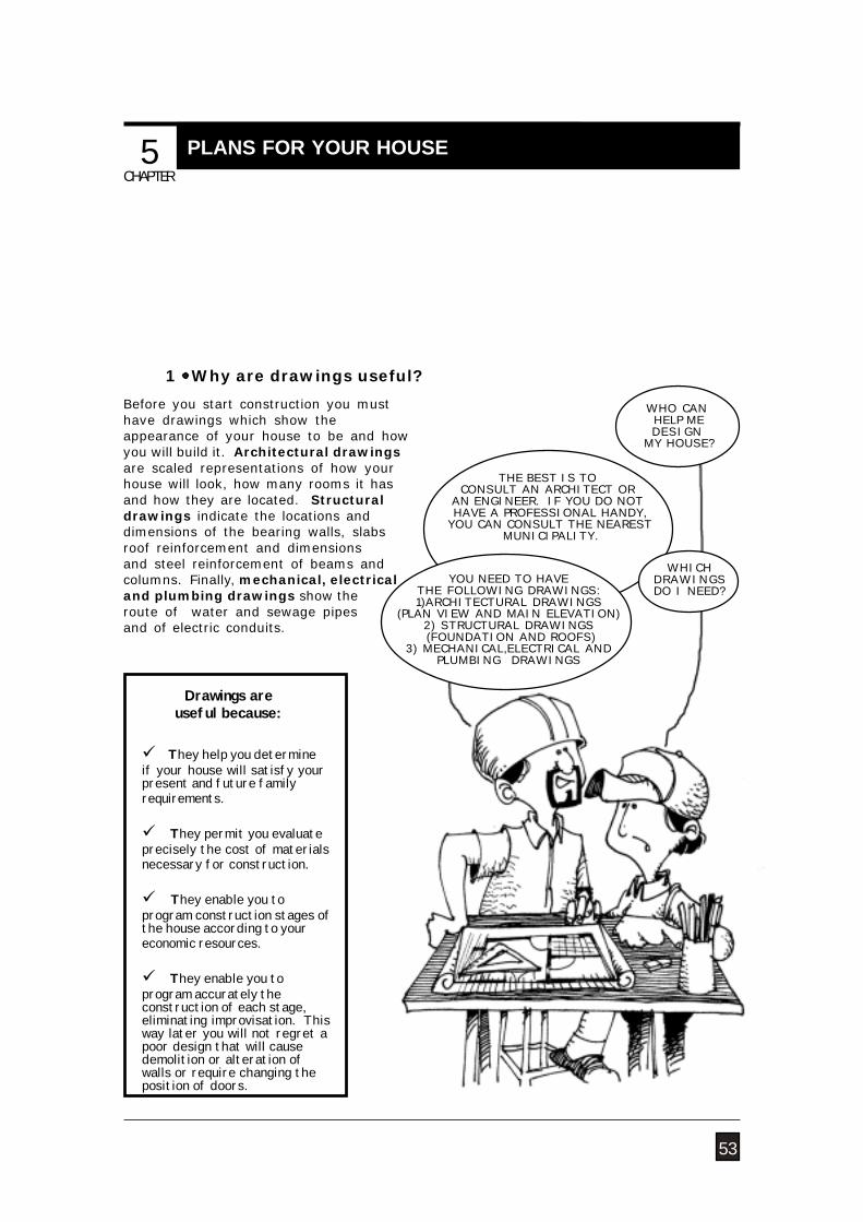
1 Why are drawings useful?
WHO CAN HELP MEDESIGN
MY HOUSE?
THE BEST IS TOCONSULT AN ARCHITECT OR
AN ENGINEER. IF YOU DO NOT HAVE A PROFESSIONAL HANDY,
YOU CAN CONSULT THE NEAREST MUNICIPALITY.
They help you determineif your house will satisfy yourpresent and future familyrequirements.
They permit you evaluateprecisely the cost of materialsnecessary for construction.
They enable you toprogram construction stages ofthe house according to youreconomic resources.
They enable you toprogram accurately theconstruction of each stage,eliminating improvisation. Thisway later you will not regret apoor design that will causedemolition or alteration ofwalls or require changing theposition of doors.
Drawings areuseful because:
YOU NEED TO HAVETHE FOLLOWING DRAWINGS:1)ARCHITECTURAL DRAWINGS
(PLAN VIEW AND MAIN ELEVATION)2) STRUCTURAL DRAWINGS (FOUNDATION AND ROOFS)
3) MECHANICAL,ELECTRICAL ANDPLUMBING DRAWINGS
WHICHDRAWINGSDO I NEED?
Before you start construction you musthave drawings which show theappearance of your house to be and howyou will build it. Architectural drawingsare scaled representations of how yourhouse will look, how many rooms it hasand how they are located. Structuraldrawings indicate the locations anddimensions of the bearing walls, slabsroof reinforcement and dimensionsand steel reinforcement of beams andcolumns. Finally, mechanical, electricaland plumbing drawings show theroute of water and sewage pipesand of electric conduits.
53
5 CAPITULO 5CAPITULO
CHAPTER
PLANS FOR YOUR HOUSE
CONSTRUCTION AND MAINTENANCE OF MASONRY HOUSES
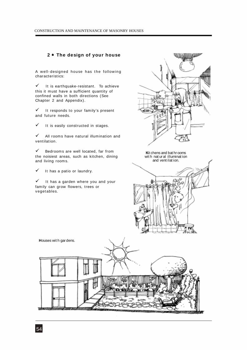
A well-designed house has the followingcharacteristics:
It is earthquake-resistant. To achievethis it must have a sufficient quantity ofconfined walls in both directions (SeeChapter 2 and Appendix).
It responds to your family’s presentand future needs.
It is easily constructed in stages.
All rooms have natural illumination andventilation.
Bedrooms are well located, far fromthe noisiest areas, such as kitchen, diningand living rooms.
It has a patio or laundry.
It has a garden where you and yourfamily can grow flowers, trees orvegetables.
Houses with gardens.
54
Kitchens and bathroomswith natural illumination
and ventilation.
2 The design of your house
NATURAL HAZARDS
Bathroom
Dining room
Bedroom
Living room
Patio
Closet
Bathroom
Kitchen
8.00
3.85
8.00
3.90
2.20
2.10
2.00
BedroomBedroom
1.95
55
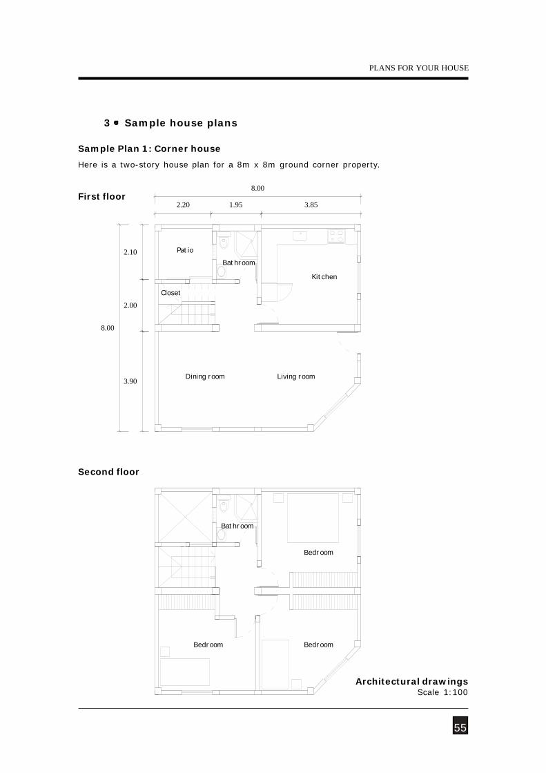
3 Sample house plans
Sample Plan 1: Corner house
First floor
Second floor
Here is a two-story house plan for a 8m x 8m ground corner property.
Architectural drawingsScale 1:100
PLANS FOR YOUR HOUSE
CONSTRUCTION AND MAINTENANCE OF MASONRY HOUSES
Living-dining room Multiple use
Bathroom
Closet
Laundry
Kitchen-dining room
Terrace
Multiple use
Garden
3.79
8.00
3.79
3.64
3.63
2.00
4.0020.00
5.00
0.80
2.10
56
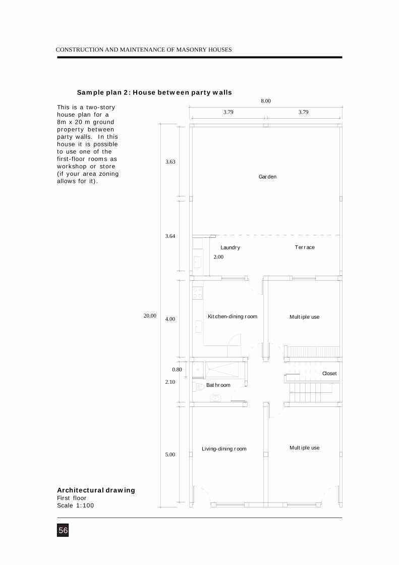
Architectural drawingFirst floorScale 1:100
Sample plan 2: House between party walls
This is a two-storyhouse plan for a8m x 20 m groundproperty betweenparty walls. In thishouse it is possibleto use one of thefirst-floor rooms asworkshop or store(if your area zoningallows for it).
NATURAL HAZARDS
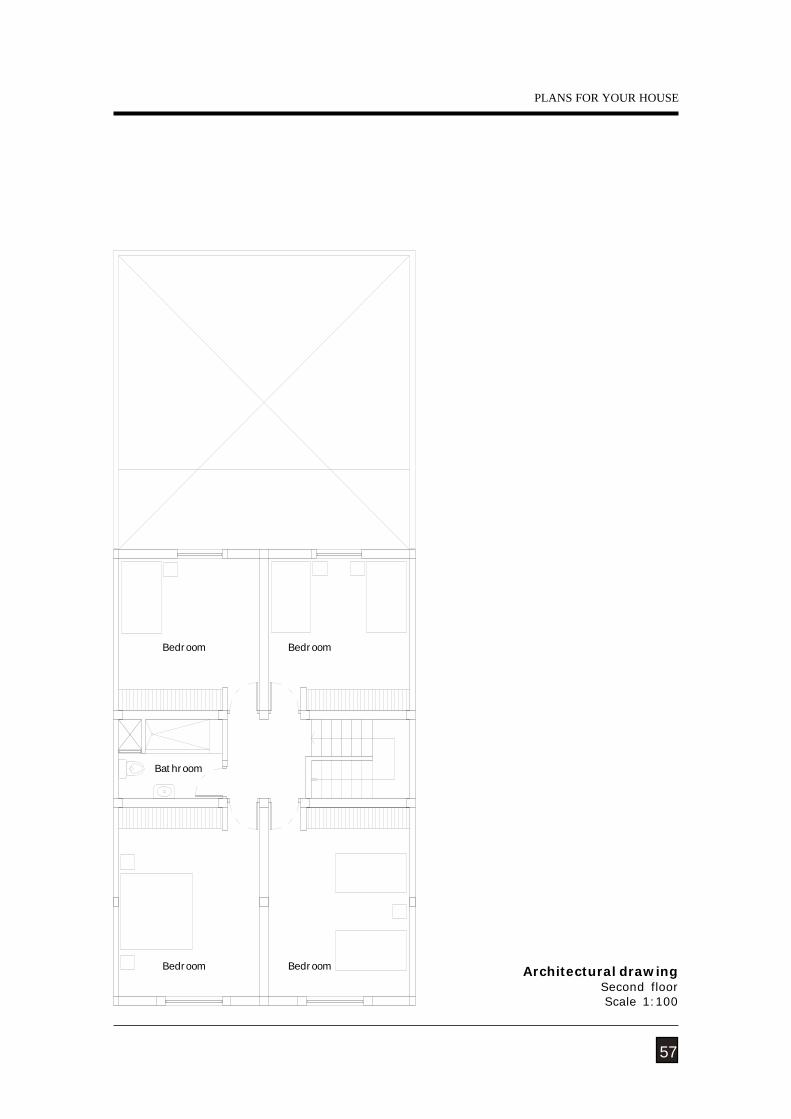
Bedroom
Bathroom
Bedroom
Bedroom Bedroom
Architectural drawingSecond floorScale 1:100
57
PLANS FOR YOUR HOUSE
CONSTRUCTION AND MAINTENANCE OF MASONRY HOUSES
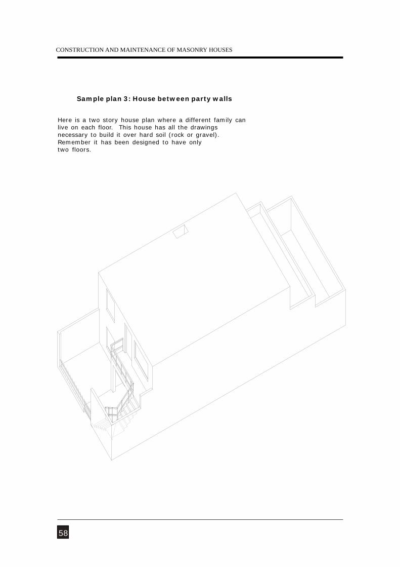
Sample plan 3: House between party walls
Here is a two story house plan where a different family canlive on each floor. This house has all the drawingsnecessary to build it over hard soil (rock or gravel).Remember it has been designed to have onlytwo floors.
58
NATURAL HAZARDS
0.15
2.40
0.25
2.40
0.25
5.45
0.15
2.40
0.25
0.90
1.50
0.25
5.45
5.45
2.40
0.25
2.40
0.25
0.15
0.90
59
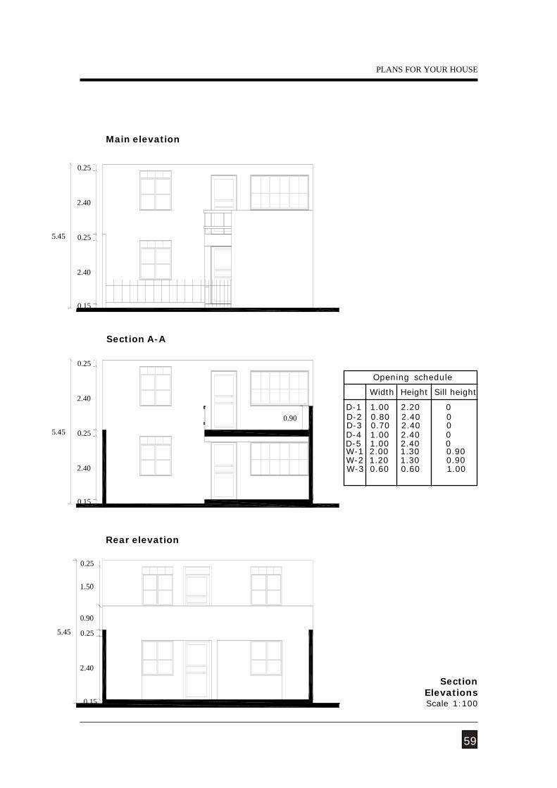
SectionElevationsScale 1:100
Rear elevation
Main elevation
Section A-A
PLANS FOR YOUR HOUSE
Opening schedule
D-1 1.00 2.20 0
Width Height Sill height
D-2 0.80 2.40 0 D-3 0.70 2.40 0 D-4 1.00 2.40 0 D-5 1.00 2.40 0 W-1 2.00 1.30 0.90 W-2 1.20 1.30 0.90 W-3 0.60 0.60 1.00
CONSTRUCTION AND MAINTENANCE OF MASONRY HOUSES
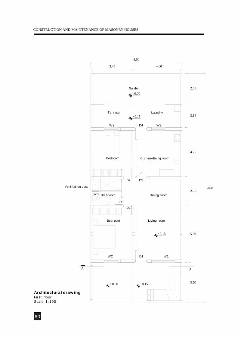
3.45
D2
D2
8.00
A
0.00- +
W2
Bedroom
Ventilation duct
D3
W3 Bathroom
Bedroom
Terrace
W2
3.500.15 +
+ 0.15
W1D1
A'
0.00 +
2.55
4.25
Kitchen-dining room
D5
Living room
Dining room
+ 0.15
-
W2D4
Laundry2.15
4.00
Garden
5.50
2.5520.00
60
Architectural drawingFirst floorScale 1:100
NATURAL HAZARDS
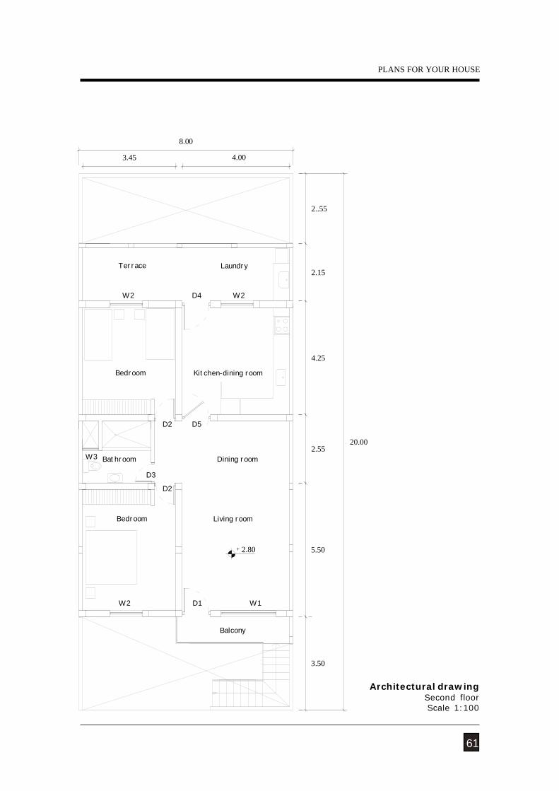
5.50
20.00
W2
2.80 +
Balcony
W1D1
3.50
2..55
D3
W3
D5
D2
D2
W2 D4 W2
4.25
2.55
2.15
4.00
8.00
3.45
Terrace Laundry
Bedroom Kitchen-dining room
Dining room
Living room
Bathroom
Bedroom
61
Architectural drawingSecond floorScale 1:100
PLANS FOR YOUR HOUSE
CONSTRUCTION AND MAINTENANCE OF MASONRY HOUSES
5.45 +
NATURAL HAZARDS
Balcony
Bathroom Dining room
Living roomBedroom
Bedroom Kitchen
LaundryTerrace
Bedroom
Bathroom
Living room
Bedroom
Dining room
Kitchen
Laundry
Garden
Terrace
Garden
63
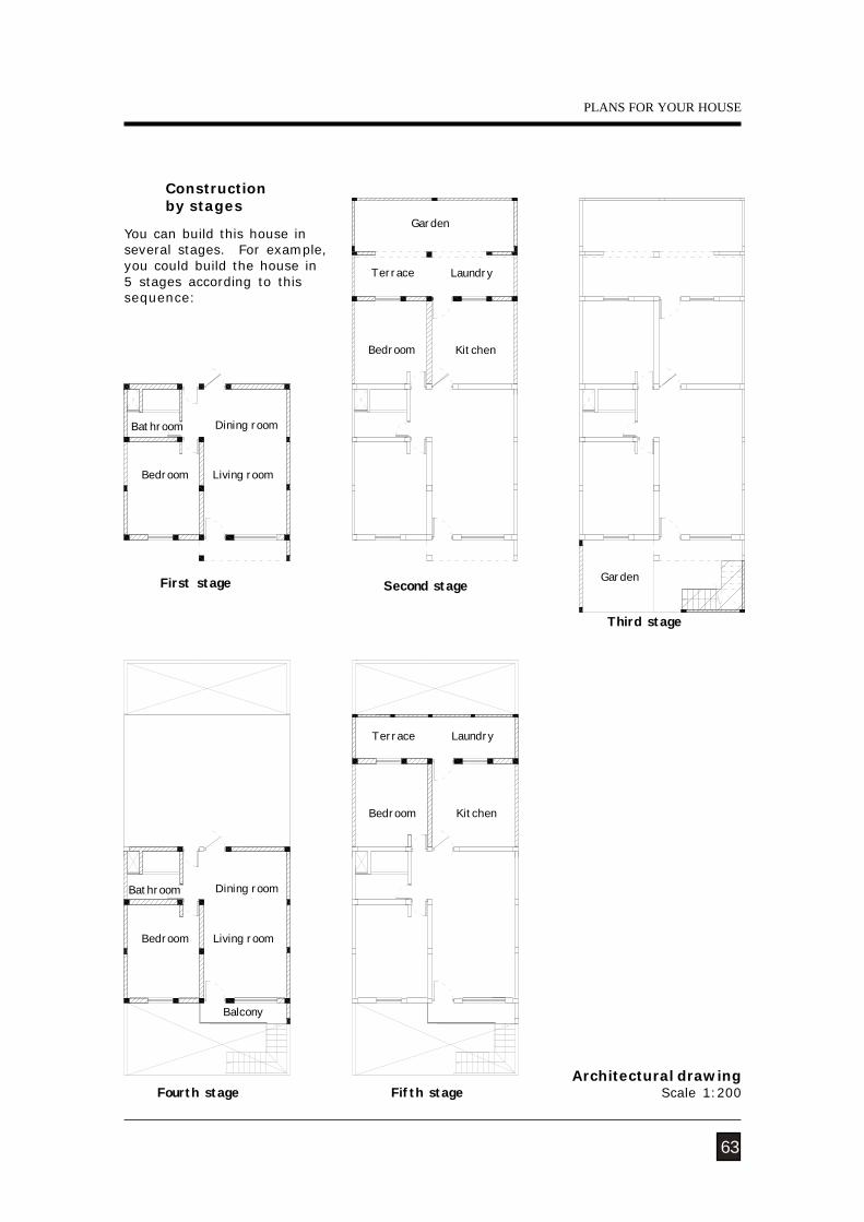
Constructionby stages
Architectural drawingScale 1:200
You can build this house inseveral stages. For example,you could build the house in5 stages according to thissequence:
First stage Second stage
Third stage
Fourth stage Fifth stage
PLANS FOR YOUR HOUSE
CONSTRUCTION AND MAINTENANCE OF MASONRY HOUSES
3 3
3.50
C-6
A
1
2.40
C-6 12cm joint
C-1
C-63
3
2
3
3
1 C-1
3
32.55
3 34.25
2.55
C-4
C-44
5
1
1
2
1
1
2
2.15
1
C-1
3
C-67
6
3
2
2
3
C-6
1 C-1
2cm joint
C-68 3
3
33 2.60
3 3Stairfoundation
3.50
4.26B
C-6 3
3
C-6
C
4C-3 1.00 1
4
1.37
C-1
11
1 1
C-2 1
C-5
2.40
1.12
C-6
C-6
3 3
C-1
33 2.55
SOG + 0.104.25
SOG + 0.10
4
4
C-1
1,49
4
4C-1
2C-6
4
4
C-4
1
1
2
C-6
3 3
C-4
2.55
4 4 1
4 4
4
C-5
C-3 4 1C-2
C-6
C-1
11
4.00
3.74
Foundation
1.26
3.74
1.04
C-4
C-4
2.60
20.00
1
2cm jointC-62
1
3 32 C-6
C-1
2.15
3 3
4.26
C-63
3C-6
widening
64
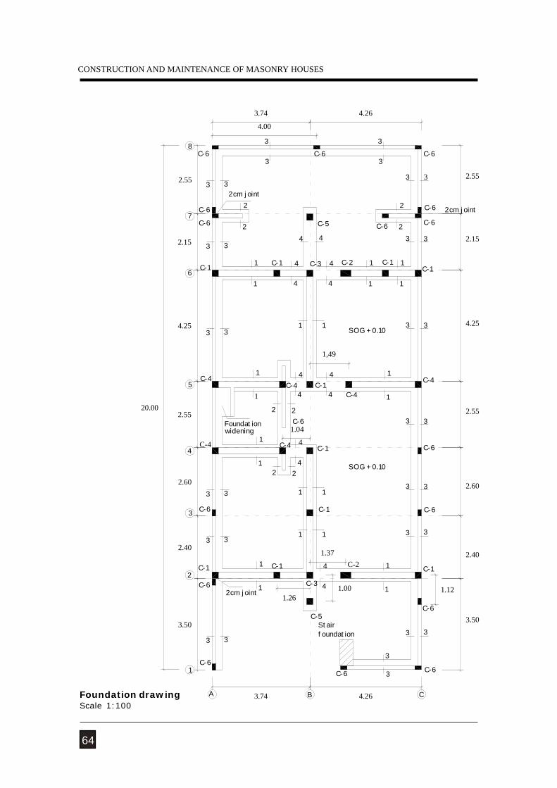
Foundation drawingScale 1:100
NATURAL HAZARDS
65
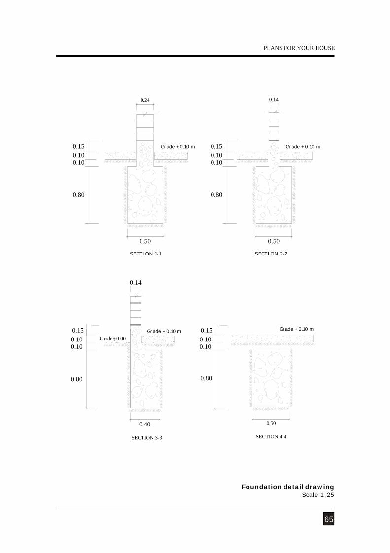
Foundation detail drawingScale 1:25
PLANS FOR YOUR HOUSE
0.15
0.80
0.100.10
0.500.40
SECTION 3-3 SECTION 4-4
-+Grade 0.000.15
0.80
0.100.10
SECTION 1-1
0.50
0.14
0.50
SECTION 2-2
0.80
0.100.100.15 0.15Grade + 0.10 m
0.80
0.100.10
0.24 0.14
Grade + 0.10 m
Grade + 0.10 m Grade + 0.10 m
CONSTRUCTION AND MAINTENANCE OF MASONRY HOUSES
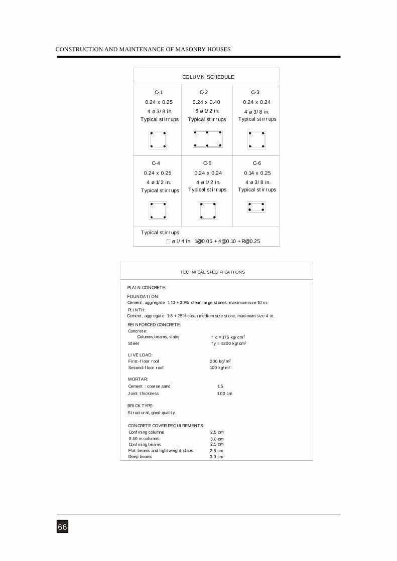
66
ø 1/4 in. [email protected] + [email protected] + [email protected]
0.24 x 0.25
Typical stirrups
0.24 x 0.25
4 ø 3/8 in.
C-5
0.24 x 0.24
4 ø 1/2 in.4 ø 1/2 in.
C-4
4 ø 3/8 in.
C-6
0.14 x 0.25
COLUMN SCHEDULE
C-2
6 ø 1/2 in.0.24 x 0.40
C-1
4 ø 3/8 in.
C-3
0.24 x 0.24
Typical stirrups Typical stirrups
Typical stirrups Typical stirrups Typical stirrups
Typical stirrups
Cement, aggregate 1:10 + 30% clean large stones, maximum size 10 in.
Structural, good quality
Confining columnsCONCRETE COVER REQUIREMENTS:
Confining beamsFlat beams and lightweight slabs
0.40 m columns
Deep beams
2.5 cm3.0 cm2.5 cm
3.0 cm2.5 cm
BRICK TYPE:
Cement : coarse sand 1:5Joint thickness 1.00 cm
REINFORCED CONCRETE:
PLAIN CONCRETE:
Columns,beams, slabs
Cement, aggregate 1:8 + 25% clean medium size stone, maximum size 4 in.
Concrete:
Steel
MORTAR:
LIVE LOAD:First-floor roofSecond-floor roof
FOUNDATION:
PLINTH:
fy = 4200 kg/cm
2f'c = 175 kg/cm
200 kg/m100 kg/m
TECHNICAL SPECIFICATIONS
2
2
2
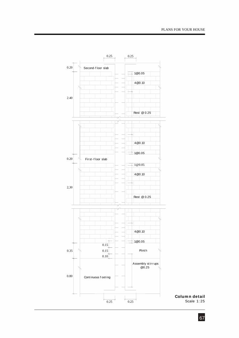
NATURAL HAZARDS
Plinth
Continuous footing
First-floor slab
Second-floor slab
Rest @ 0.25
Assembly stirrups @0.25
Rest @ 0.25
0.80
0.25 0.25
0.35
0.10
0.15
0.15
0.20
2,30
2.40
0.20
0.250.25
67
Column detailScale 1:25
PLANS FOR YOUR HOUSE
CONSTRUCTION AND MAINTENANCE OF MASONRY HOUSES
1ø3/8in.
1ø3/8in.
1ø3/8in.
1ø3/8in.1ø3/8in.
1ø8m
m
1ø3/8in.
1ø3/8in.1ø3/8in. 1ø3/8in.
1ø3/8in. 1ø3/8in.1ø3/8in.
1ø3/8in.
1ø3/8in.
1ø3/
8in.
1ø3/
8in.
1ø3/8in. 1ø3/8in.
1ø3/8in. 1ø3/8in.
CB-2
CB-2
CB
-2
CB-2
CB-2
CB-2
CB-2
CB-2
CB-2
CB-2
B1(.24x.40)
Rises Pa
Rises Pa
Rises Pa
Rises Pa
Rises Pa
B4(.24x.40)
8
7
6
2.15
2.55
4
5
2.55
3
2
2.40
2.60
1
3.50
20.00
4.25
See parapetconnectiondetail
1ø8m
m
1ø8m
m
1ø3/8in.
1ø3/8in. 1ø3/8in.
1ø3/8in.
See stairs
776 6
2 2
0.80
0,70
0.300.70
0.70
0.700.300.70
881
11
1
CB-1TB1
CB-1
5
54
43
3
3
3
4
4
3
3
0.50
1
1
1
1
2
2
2
2
1
11
1
B3(.24x.40)
TB1
1
1
4
4
TB1
CB-2
CB-1
Solid slab
0.20 0.400.70 0.30
0.300.700.30 0.700.70
B2 B2(.24x.40)
B1(.24x.40)
D
C
A
B
A
0.50
1.00
Duct,onlyjoists pass
0.50
0.50
0.700.70
0.60 0.80
0.70 0.70
0.80
8.00
CBA 4.263.74
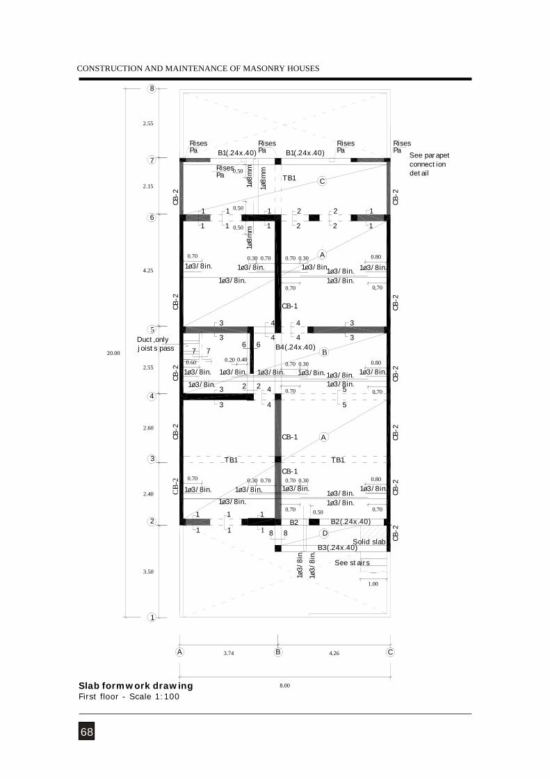
68
Slab formwork drawingFirst floor - Scale 1:100
NATURAL HAZARDS
1ø3/8in.1ø3/8in.1ø3/8in. 1ø3/8in. 1ø3/8in.
1ø3/8in. 1ø3/8in.1ø3/8in.
1ø3/8in. 1ø3/8in. 1ø3/8in.
B4(.24x.40)
8
7
6
2.15
2.55
4
5
2.55
3
2
2.40
2.60
1
3.50
20.00
4.25
Duct, onlyjoists pass
CB-2
1ø3/8in.
1ø3/8in.
1ø3/8in.
1ø3/8in. 1ø3/8in.
1ø3/8in.
1ø3/8in.1ø3/8in.
1ø3/8in. 1ø3/8in.
1ø3/8in.
2
2
1
1
CB-2
3
3
0.70
0.80A
CB-1
4
4
1
1
2
2
1
1
4
4
0.30 0.70
0.70
0.70 0.30
66
0.80
0.70
5
5
CB-2
CB-2
TB1
0.80
0.70
A
0.700.30 0.70 0.30
0.300.700.400.20
TB1
4
4
CB-1
CB-1
22
B
CB-2
C
B2(.24x.40)
B
B21
1 1
1
4.26
0.700.70 0.50
1
1
CB-2
0.70
0.60
0.70
CB-2
CB-2
CB-2
7 7
A
1
1
3.74
8.00
3
3
3
3
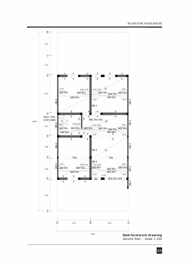
69
Slab formwork drawingSecond floor - Scale 1:100
PLANS FOR YOUR HOUSE
CONSTRUCTION AND MAINTENANCE OF MASONRY HOUSES
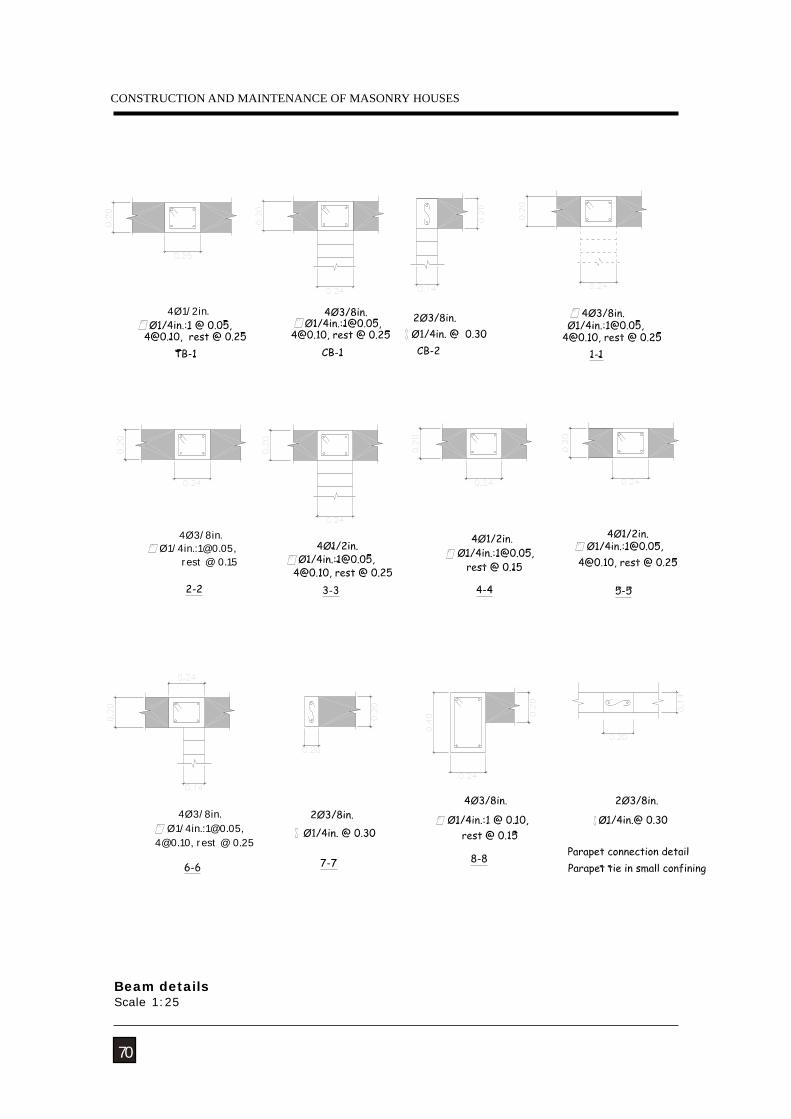
rest @ 0.15
4Ø3/8in.Ø1/4in.:[email protected],
4Ø1/2in.
4Ø3/8in.Ø1/4in.:[email protected],
[email protected], rest @ 0.25
70
Beam detailsScale 1:25
NATURAL HAZARDS
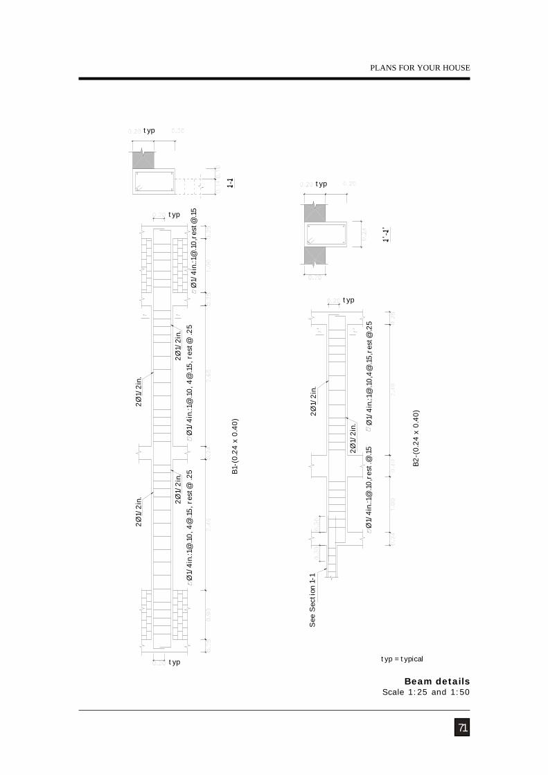
B1-(
0.24
x 0
.40)
Ø1/
4in.
:1@
.10, 4
@.1
5, r
est@
.25
2Ø1/
2in.
2Ø1/
2in.
Ø1/
4in.
:1@
.10, 4
@.15
, res
t@ .2
52Ø
1/2i
n.
2Ø1/
2in.
Ø1/
4in.
:1@
.10,r
est@
.15
B2-(
0.24
x 0
.40)
See
Sect
ion
1-1
Ø1/
4in.
:1@
.10,r
est.
@.15
Ø1/
4in.
:1@
.10,
,res
5
2Ø1/
2in.
2Ø1/
2in.
typ
typ = typical
typ
typ
typ
typ
71
Beam detailsScale 1:25 and 1:50
PLANS FOR YOUR HOUSE
CONSTRUCTION AND MAINTENANCE OF MASONRY HOUSES
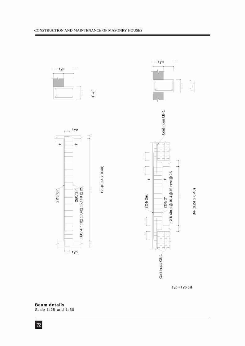
2Ø1/
2in.
1'
2Ø3/
8in.
1'
B4-(
0.24
x 0
.40)
Ø1/
4in.
:1@
.10,4
@.1
5,re
st@
.25
B3-(
0.24
x 0
.40)
Cont
inue
s CB
-1
Ø1/
4in.
:1@
.10,4
@.15
,res
5
2Ø1/
2"
2Ø1/
2in.
Cont
inue
s CB
-11'1'
typ = typical
typ
typ
typ
typ
72
Beam detailsScale 1:25 and 1:50
NATURAL HAZARDS
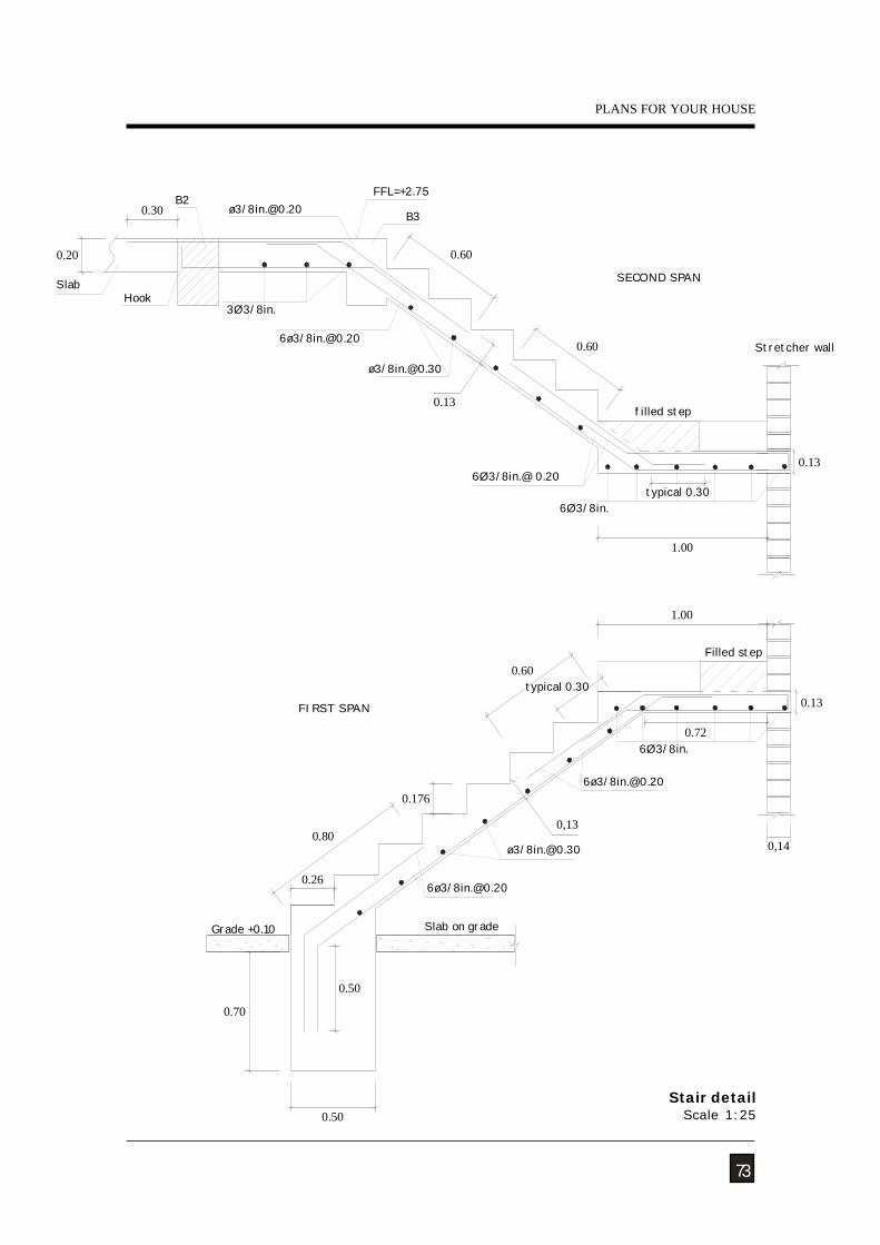
0.80
0.50
0.50
0.26
0.70
Slab on grade
0.60
filled step
SECOND SPAN
FIRST SPAN
Grade +0.10
6Ø3/8in.
SlabHook
3Ø3/8in.
6Ø3/8in.@ 0.20
6Ø3/8in.
FFL=+2.75
B3
Filled step
Stretcher wall
typical 0.30
0.72
1.00
1.00
0.13
0.60
0,13
0.176
typical 0.30
0.30
0.20 0.60
0,14
0.13
0.13
73
Stair detailScale 1:25
PLANS FOR YOUR HOUSE
CONSTRUCTION AND MAINTENANCE OF MASONRY HOUSES
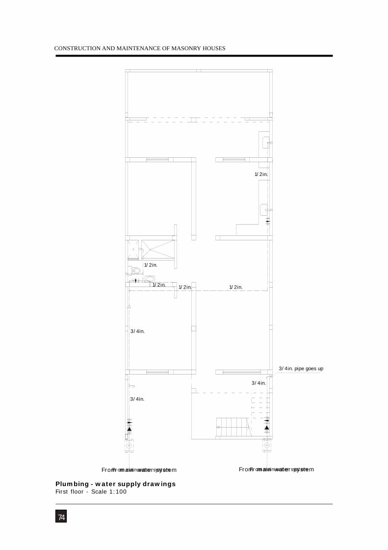
From main water system
3/4in.
3/4in.
3/4in. pipe goes up
3/4in.
1/2in.
1/2in.
1/2in.
1/2in.
From main water system
1/2in.
74
Plumbing - water supply drawingsFirst floor - Scale 1:100
From main water system From main water system
NATURAL HAZARDS
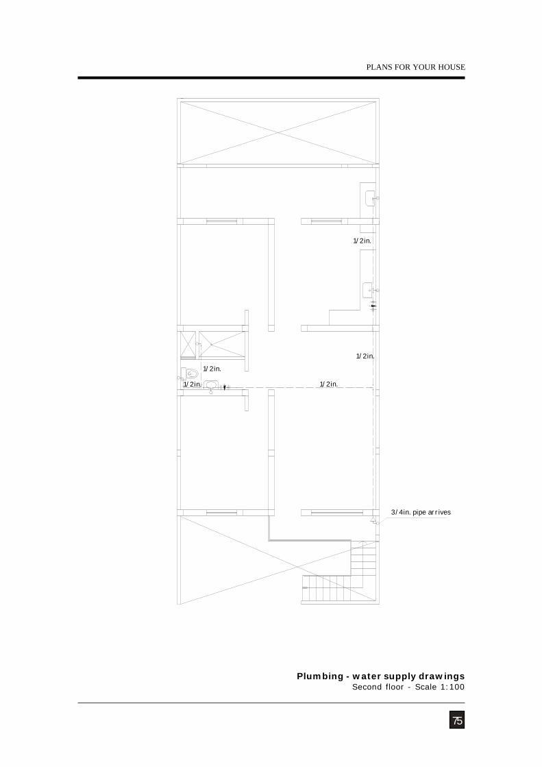
75
Plumbing - water supply drawingsSecond floor - Scale 1:100
PLANS FOR YOUR HOUSE
1/2in.
3/4in. pipe arrives
1/2in.
1/2in.
1/2in.
1/2in.
CONSTRUCTION AND MAINTENANCE OF MASONRY HOUSES
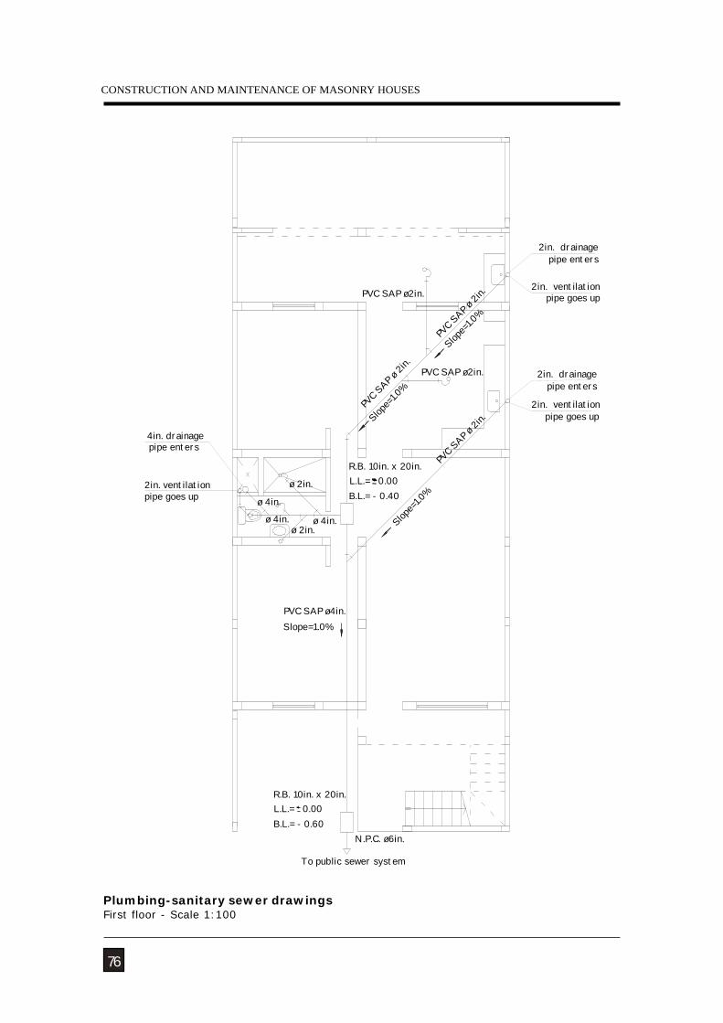
R.B. 10in. x 20in.
To public sewer system
L.L.= 0.00B.L.= - 0.60
N.P.C. ø6in.
Slope=1.0%PVC SAP ø4in.
pipe enters 4in. drainage
PVC S
AP ø 2i
n.
B.L.= - 0.40L.L.= 0.00R.B. 10in. x 20in.
ø 4in.
ø 2in.ø 4in.ø 4in.
ø 2in.
PVC S
AP ø 2i
n.
Slope=
1.0%
PVC S
AP ø 2i
n.PVC SAP ø2in.
PVC SAP ø2in.
2in. ventilationpipe goes up
2in. ventilationpipe goes up
2in. drainage pipe enters
2in. ventilationpipe goes up
2in. drainage pipe enters
Slope=
1.0%
Slope=
1.0%
76
Plumbing-sanitary sewer drawingsFirst floor - Scale 1:100
NATURAL HAZARDS
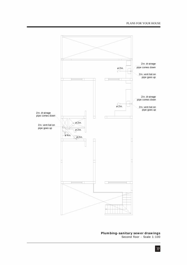
77
Plumbing-sanitary sewer drawingsSecond floor - Scale 1:100
PLANS FOR YOUR HOUSE
ø 4in.
ø 2in.
ø 2in. pipe comes down 2in. drainage
2in. ventilationpipe goes up
2in. drainagepipe comes down
2in. ventilationpipe goes up
2in. ventilationpipe goes up
pipe comes down 2in. drainage
ø 2in.
ø 2in.
ø 2in.
CONSTRUCTION AND MAINTENANCE OF MASONRY HOUSES
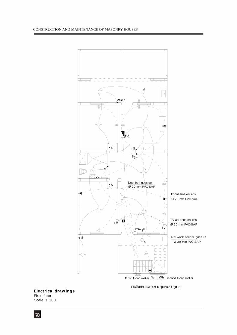
d
2Sc,d
Doorbell goes upØ 20 mm PVC-SAP
32Sa, b
S
TV
Ø 20 mm PVC-SAPPhone line enters
Ø 20 mm PVC-SAPTV antenna enters
TV
S b3
b
T-1
S S
S
S
c
Network feeder goes up
Wh
a
First floor meter
FROM ELECTRIC NET SYSTEM
Ø 20 mm PVC-SAP
Second floor meterWh
b
78
Electrical drawingsFirst floorScale 1:100
From electric power grid
NATURAL HAZARDS
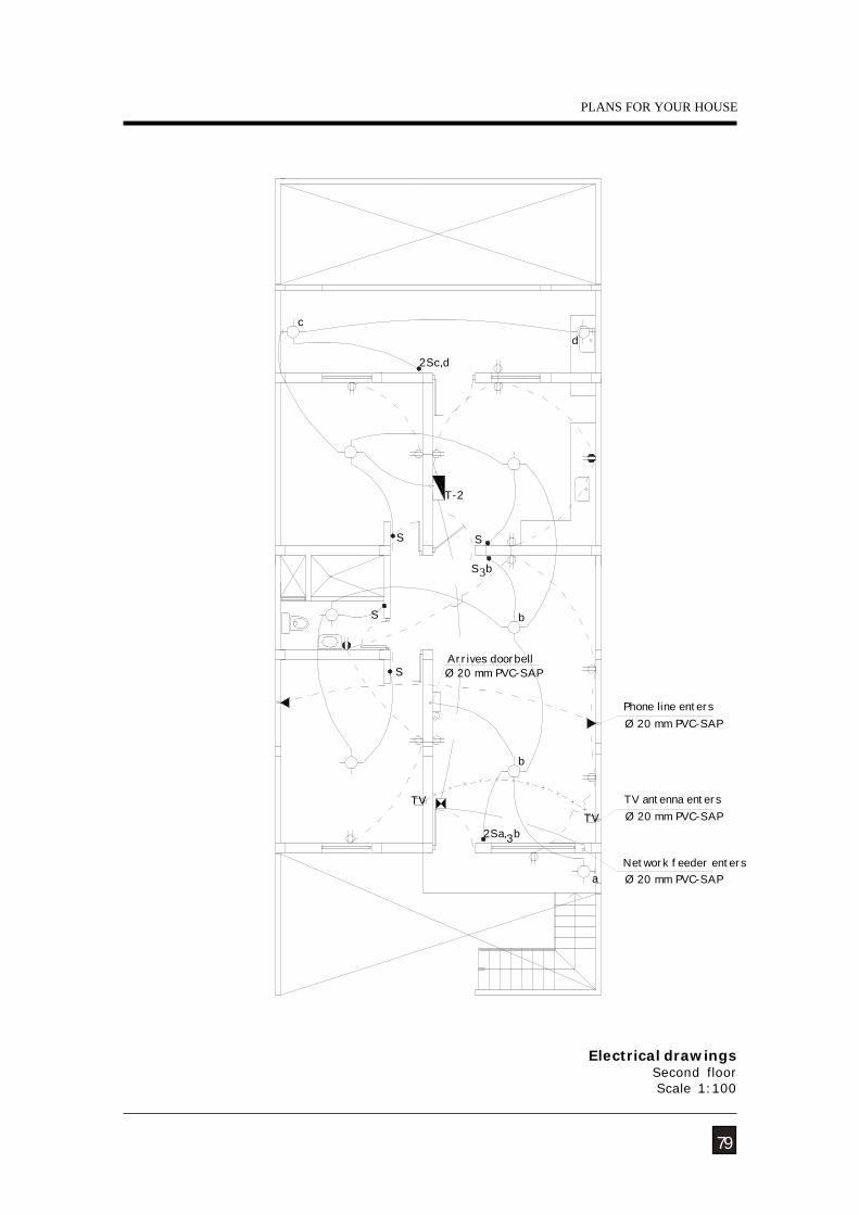
3S b
b
T-2
S
SS
c
2Sc,d
d
Ø 20 mm PVC-SAP
b
32Sa, b
Arrives doorbellS
TV
Network feeder entersØ 20 mm PVC-SAPa
Ø 20 mm PVC-SAPTV antenna enters
Ø 20 mm PVC-SAPPhone line enters
TV
79
Electrical drawingsSecond floorScale 1:100
PLANS FOR YOUR HOUSE
CONSTRUCTION AND MAINTENANCE OF MASONRY HOUSES
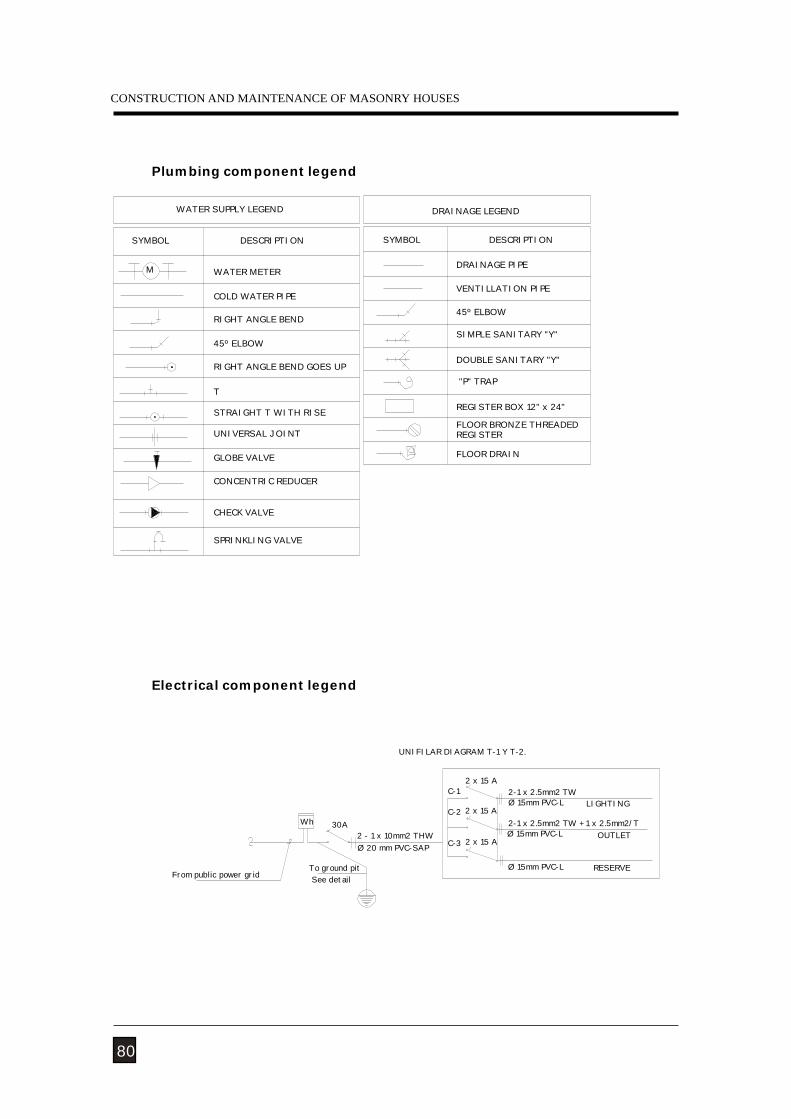
UNIFILAR DIAGRAM T-1 Y T-2.
To ground pit
Wh
From public power grid See detail
30A2 - 1 x 10mm2 THW Ø 20 mm PVC-SAP
2 x 15 AC-2
Ø 15mm PVC-L
Ø 15mm PVC-L
2-1 x 2.5mm2 TW + 1 x 2.5mm2/T
2 x 15 AC-3OUTLET
RESERVE
2-1 x 2.5mm2 TW Ø 15mm PVC-L
2 x 15 AC-1
LIGHTING
CONCENTRIC REDUCER
CHECK VALVE
SPRINKLING VALVE
GLOBE VALVE
RIGHT ANGLE BEND
RIGHT ANGLE BEND GOES UP
45º ELBOW
COLD WATER PIPE
UNIVERSAL JOINT
STRAIGHT T WITH RISE
T
SIMPLE SANITARY "Y"
DOUBLE SANITARY "Y"
"P" TRAP
VENTILLATION PIPE
45º ELBOW
FLOOR BRONZE THREADED REGISTER
REGISTER BOX 12" x 24"
FLOOR DRAIN
SYMBOL
WATER SUPPLY LEGEND
WATER METER
SYMBOL
M
DESCRIPTION DESCRIPTION
DRAINAGE PIPE
DRAINAGE LEGEND
80
Plumbing component legend
Electrical component legend
NATURAL HAZARDS
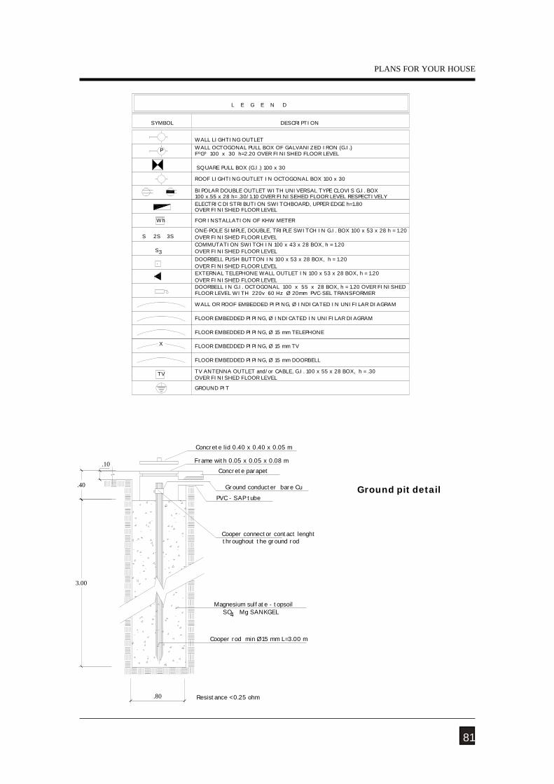
.80
3.00
.40
.10
Resistance < 0.25 ohm
SO Mg SANKGELMagnesium sulfate - topsoil
Cooper rod min Ø15 mm L=3.00 m
4
Frame with 0.05 x 0.05 x 0.08 m
PVC - SAP tube
Concrete parapet
Concrete lid 0.40 x 0.40 x 0.05 m
throughout the ground rod
Ground conducter bare Cu
Cooper connector contact lenght
81
Ground pit detail
PLANS FOR YOUR HOUSE
TV TV ANTENNA OUTLET and/or CABLE, G.I. 100 x 55 x 28 BOX, h = .30
GROUND PIT
WALL OCTOGONAL PULL BOX OF GALVANIZED IRON (G.I.)
BIPOLAR DOUBLE OUTLET WITH UNIVERSAL TYPE CLOVIS G.I. BOX
DOORBELL IN G.I. OCTOGONAL 100 x 55 x 28 BOX, h = 1.20 OVER FINISHED
EXTERNAL TELEPHONE WALL OUTLET IN 100 x 53 x 28 BOX, h = 1.20
ONE-POLE SIMPLE, DOUBLE, TRIPLE SWITCH IN G.I. BOX 100 x 53 x 28 h = 1.20
COMMUTATION SWITCH IN 100 x 43 x 28 BOX, h = 1.20
ELECTRIC DISTRIBUTION SWITCHBOARD, UPPER EDGE h=1.80
DOORBELL PUSH BUTTON IN 100 x 53 x 28 BOX, h = 1.20.
X
P
Wh
3S2SS
S3
FLOOR LEVEL WITH 220v 60 Hz Ø 20mm PVC-SEL TRANSFORMER
WALL OR ROOF EMBEDDED PIPING, Ø INDICATED IN UNIFILAR DIAGRAM
SQUARE PULL BOX (G.I.) 100 x 30
FOR INSTALLATION OF KHW METER
FºGº 100 x 30 h=2.20 OVER FINISHED FLOOR LEVEL
OVER FINISHED FLOOR LEVEL
SYMBOL
WALL LIGHTING OUTLET
L E G E N D
DESCRIPTION
ROOF LIGHTING OUTLET IN OCTOGONAL BOX 100 x 30
100 x.55 x 28 h= .30/1.10 OVER FINISEHED FLOOR LEVEL RESPECTIVELY
OVER FINISHED FLOOR LEVEL
OVER FINISHED FLOOR LEVEL
OVER FINISHED FLOOR LEVEL
OVER FINISHED FLOOR LEVEL
FLOOR EMBEDDED PIPING, Ø INDICATED IN UNIFILAR DIAGRAM
FLOOR EMBEDDED PIPING, Ø 15 mm TELEPHONE
FLOOR EMBEDDED PIPING, Ø 15 mm TV
FLOOR EMBEDDED PIPING, Ø 15 mm DOORBELL
OVER FINISHED FLOOR LEVEL

CONSTRUCTION AND MAINTENANCE OF MASONRY HOUSES
82
- Arnold C. y Reitherman R. 1987. Configuración y diseño sísmico de edificios(Configuration and seismic design of buildings). Editorial Limusa. México.
- Lesur L. 2001. Manual de albañilería y autoconstrucción I y II (Handbook ofmasonry and self construction I and II). Editorial Trillas. México.
- San Bartolomé A. 1994. Construcciones de albañilería –Comportamiento sísmico ydiseño estructural (Masonry constructions – Seismic behaviour and structural design).Fondo Editorial de la PUCP. Lima, Perú.
- Servicio Nacional de Aprendizaje. 2003. Construcción de casas sismorresistentes deuno y dos pisos (Construction of seismic resistant houses of one and two floors).Universidad Nacional de Colombia. Colombia.
REFERENCES
NATURAL HAZARDS
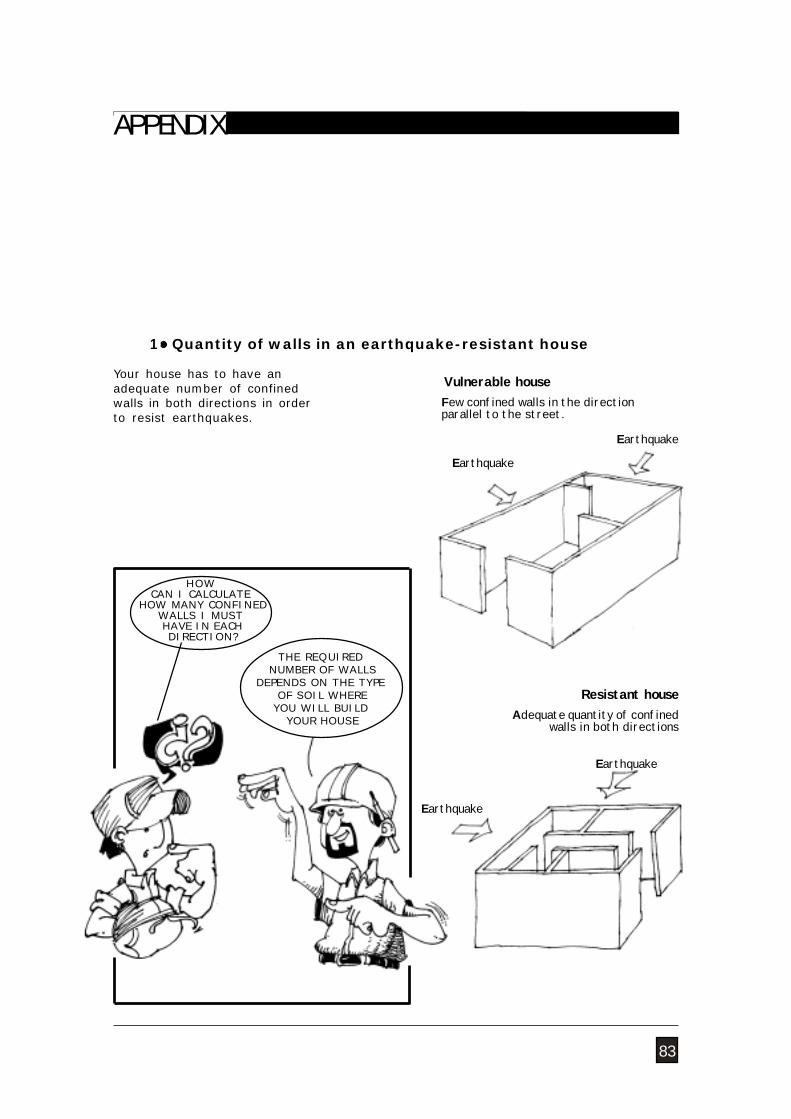
1 Quantity of walls in an earthquake-resistant house
Your house has to have anadequate number of confinedwalls in both directions in orderto resist earthquakes.
Few confined walls in the directionparallel to the street.
Vulnerable house
HOWCAN I CALCULATE
HOW MANY CONFINEDWALLS I MUST HAVE IN EACH DIRECTION?
Resistant houseAdequate quantity of confined
walls in both directions
83
Earthquake
THE REQUIRED NUMBER OF WALLS
DEPENDS ON THE TYPE OF SOIL WHEREYOU WILL BUILD
YOUR HOUSE
APPENDIX
Earthquake
Earthquake
Earthquake
CONSTRUCTION AND MAINTENANCE OF MASONRY HOUSES
84
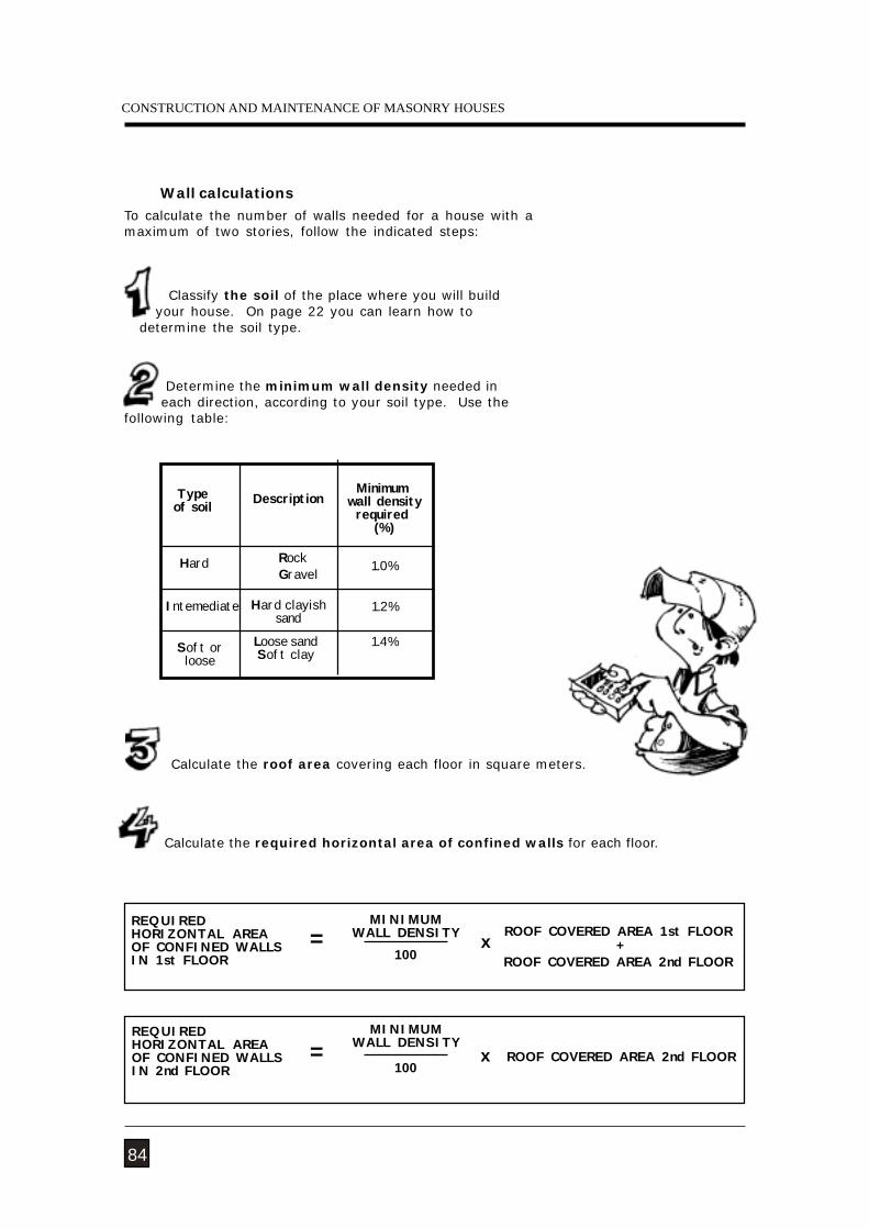
To calculate the number of walls needed for a house with amaximum of two stories, follow the indicated steps:
Wall calculations
Calculate the required horizontal area of confined walls for each floor.
Calculate the roof area covering each floor in square meters.
Determine the minimum wall density needed in each direction, according to your soil type. Use thefollowing table:
Classify the soil of the place where you will build your house. On page 22 you can learn how to determine the soil type.
Blando
Typeof soil Description
Minimum wall density
required (%)
1.4%
HardGravel
Intemediate
Rock
Hard clayishsand
Loose sandSoft clay
1.0%
1.2%
Soft orloose
REQUIREDHORIZONTAL AREAOF CONFINED WALLSIN 1st FLOOR
MINIMUMWALL DENSITY
100
ROOF COVERED AREA 1st FLOOR +
ROOF COVERED AREA 2nd FLOOR= x
REQUIREDHORIZONTAL AREAOF CONFINED WALLSIN 2nd FLOOR 100
= xMINIMUM
WALL DENSITYROOF COVERED AREA 2nd FLOOR
NATURAL HAZARDS
85
APPENDIX
To calculate the horizontal wall areaneeded in the first floor, consider theroof covering areas of the first andsecond floors. That is, the wall arearequired by the first floor will be:
Suppose that your house will beconstructed over a compact gravel-coarse sand soil and that it will have 70m² of roof covering area in the firstfloor and 50 m² in the second floor.Wall density required for hard soil is1%.
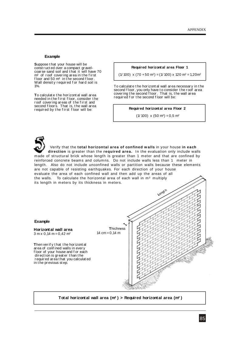
Example
14 cm = 0,14 m
Length
Total horizontal wall area (m²) > Required horizontal area (m²)
Horizontal wall area3 m x 0,14 m = 0,42 m2
Then verify that the horizontalarea of confined walls in everyfloor of your house and for each direction is greater than the required area that you calculatedin the previous step.
Required horizontal area Floor 2
(1/100) x (50 m2) = 0,5 m2
Required horizontal area Floor 1
(1/100) x (70 + 50 m2) = (1/100) x 120 m2 = 1,20m2
To calculate the horizontal wall area necessary in thesecond floor, you only have to consider the roof areacovering the second floor. That is, the wall arearequired for the second floor will be:
Verify that the total horizontal area of confined walls in your house in each direction is greater than the required area. In the evaluation only include wallsmade of structural brick whose length is greater than 1 meter and that are confined byreinforced concrete beams and columns. Do not include walls less than 1 meter inlength. Also do not include unconfined walls or partition walls because these elementsare not capable of resisting earthquakes. For each direction of your houseevaluate the area of each confined wall and then add up the areas of allthe walls. To calculate the horizontal area of each wall in m² multiplyits length in meters by its thickness in meters.
Thichness
Example
CONSTRUCTION AND MAINTENANCE OF MASONRY HOUSES
86
3.142.82
1.50
2.82
W3
W2
0.24
0.24
W10.24
W40.24
1.50
0.14
1.50
1.50
W5 W60.24
W7
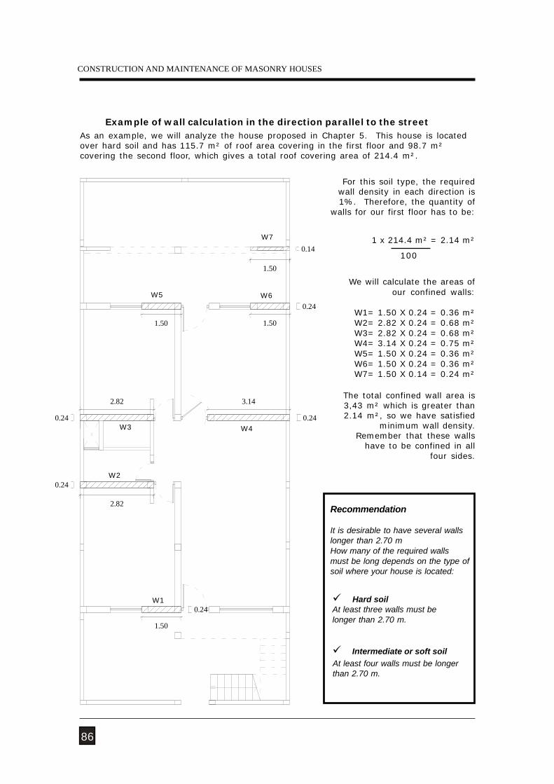
Example of wall calculation in the direction parallel to the streetAs an example, we will analyze the house proposed in Chapter 5. This house is locatedover hard soil and has 115.7 m² of roof area covering in the first floor and 98.7 m²covering the second floor, which gives a total roof covering area of 214.4 m².
We will calculate the areas ofour confined walls:
W1= 1.50 X 0.24 = 0.36 m²W2= 2.82 X 0.24 = 0.68 m²W3= 2.82 X 0.24 = 0.68 m²W4= 3.14 X 0.24 = 0.75 m²W5= 1.50 X 0.24 = 0.36 m²W6= 1.50 X 0.24 = 0.36 m²W7= 1.50 X 0.14 = 0.24 m²
The total confined wall area is3,43 m² which is greater than2.14 m², so we have satisfied
minimum wall density. Remember that these walls
have to be confined in all four sides.
For this soil type, the requiredwall density in each direction is1%. Therefore, the quantity of
walls for our first floor has to be:
Recommendation
It is desirable to have several wallslonger than 2.70 mHow many of the required wallsmust be long depends on the type ofsoil where your house is located:
Hard soilAt least three walls must belonger than 2.70 m.
At least four walls must be longerthan 2.70 m.
Intermediate or soft soil
1 x 214.4 m² = 2.14 m²
100
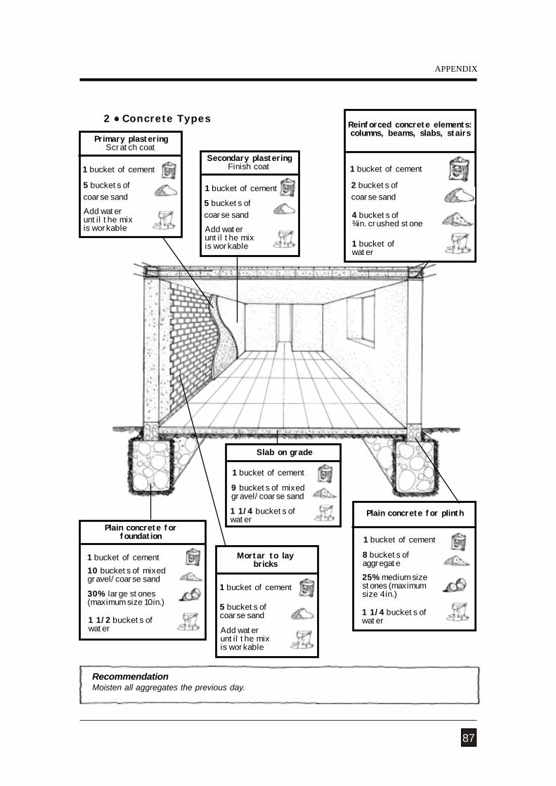
NATURAL HAZARDS
87
APPENDIX
2 Concrete Types
RecommendationMoisten all aggregates the previous day.
Plain concrete for plinth
8 buckets ofaggregate25% medium sizestones (maximumsize 4in.)
Primary plasteringScratch coat
Secondary plasteringFinish coat
Reinforced concrete elements:columns, beams, slabs, stairs
1 bucket ofwater
4 buckets of¾in. crushed stone
1 1/4 buckets ofwater
5 buckets ofcoarse sandAdd wateruntil the mixis workable
Slab on grade
1 1/4 buckets ofwater
9 buckets of mixedgravel/coarse sand
Mortar to laybricks
5 buckets ofcoarse sand
Add wateruntil the mixis workable
Plain concrete forfoundation
30% large stones(maximum size 10in.)
1 1/2 buckets ofwater
1 bucket of cement
1 bucket of cement5 buckets ofcoarse sandAdd wateruntil the mixis workable
1 bucket of cement
2 buckets ofcoarse sand
1 bucket of cement
1 bucket of cement
1 bucket of cement
1 bucket of cement10 buckets of mixedgravel/coarse sand
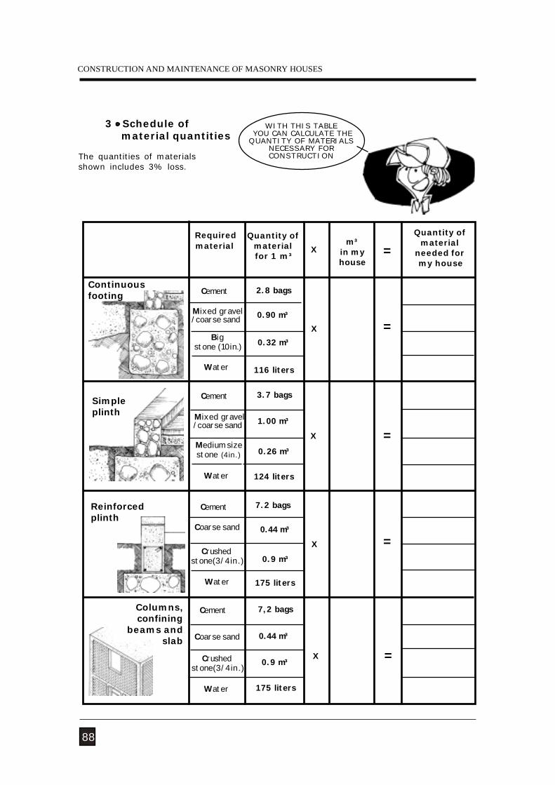
CONSTRUCTION AND MAINTENANCE OF MASONRY HOUSES
88
3 Schedule of material quantities
The quantities of materialsshown includes 3% loss.
WITH THIS TABLE YOU CAN CALCULATE THEQUANTITY OF MATERIALS
NECESSARY FORCONSTRUCTION
Requiredmaterial
Quantity ofmaterial for 1 m³
Cement
Big stone (10in.)
Mixed gravel/coarse sand
Medium sizestone (4in.)
Water
Cement
2.8 bags
0.90 m³
0.32 m³
116 liters
3.7 bags
1.00 m³
124 liters
0.26 m³
m³in myhouse
Quantity ofmaterial
needed for my house
Cement
Cement
Coarse sand
Crushed stone(3/4in.)
7.2 bags
0.44 m³
0.9 m³
175 liters
7,2 bags
0.44 m³
0.9 m³
175 liters
=
X =
X =
=X
X
X =
Columns,confining
beams andslab
Reinforcedplinth
Mixed gravel/coarse sand
Water
Water
Coarse sand
Water
Continuousfooting
Simpleplinth
Crushed stone(3/4in.)
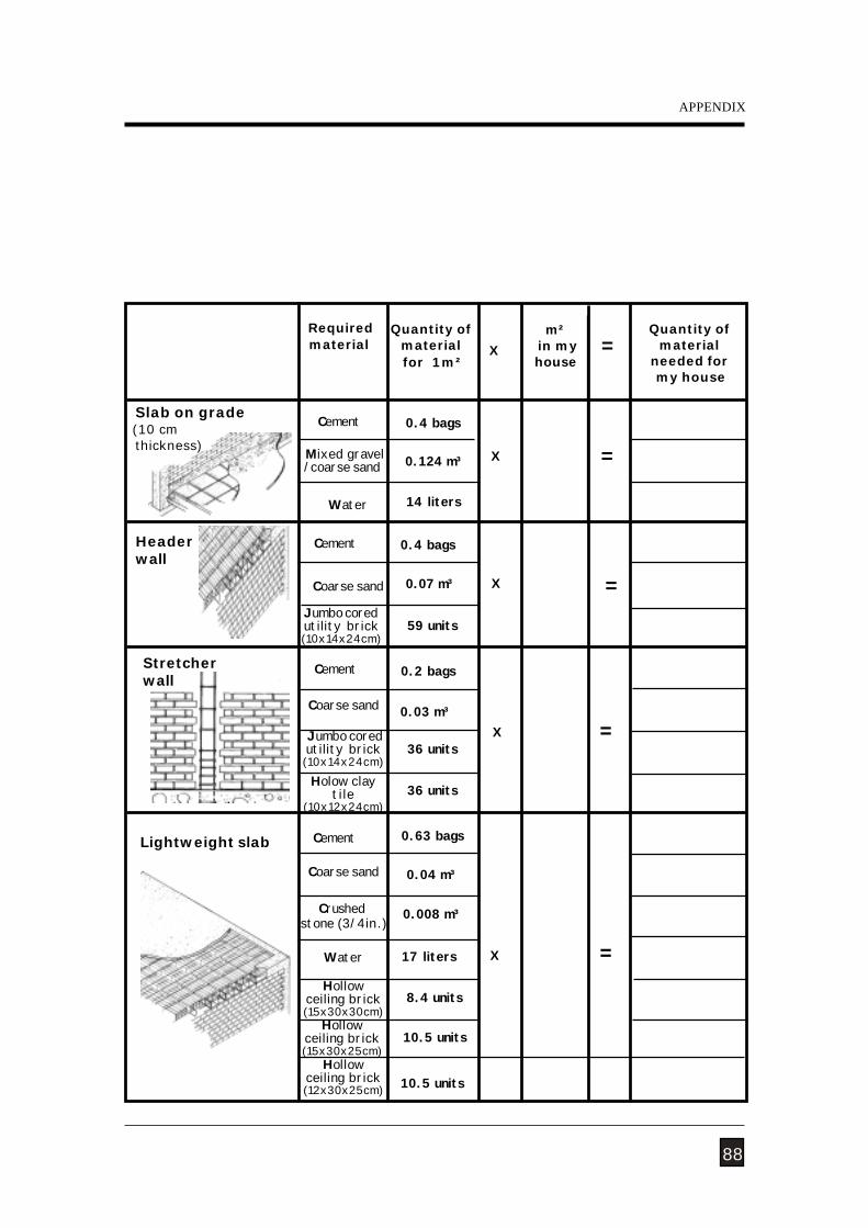
NATURAL HAZARDS
88
APPENDIX
Quantity ofmaterial for 1m²
Cement
Jumbo coredutility brick(10x14x24cm)
Cement
0.4 bags
0.124 m³
14 liters
0.4 bags
0.07 m³
59 units
0.03 m³
0.2 bags
m² in myhouse
Cement
Jumbo coredutility brick(10x14x24cm)Holow clay
tile(10x12x24cm)
Cement
Hollowceiling brick(12x30x25cm)
Hollowceiling brick(15x30x25cm)
Hollowceiling brick(15x30x30cm)
Headerwall
Lightweight slab
36 units
36 units
0.63 bags
0.04 m³
0.008 m³
17 liters
10.5 units
10.5 units
8.4 units
X =
=X
X =
=X
X =
Slab on grade (10 cm thickness)
Stretcherwall
Requiredmaterial
Quantity ofmaterial
needed for my house
Mixed gravel/coarse sand
Water
Coarse sand
Coarse sand
Coarse sand
Water
Crushed stone (3/4in.)
CONSTRUCTION AND MAINTENANCE OF MASONRY HOUSES