proposal of a standard for seismic design...
TRANSCRIPT
Institute of Industrial Science, University of Tokyo Bulletin of ERS, No. 37
PROPOSAL OF A STANDARD FOR SEISMIC DESIGN OF CONFINED MASONRY
BUILDINGS
Angel SAN BARTOLOME1, Daniel QUIUN1 and Paola MAYORCA2
ABSTRACT: A design procedure for confined masonry buildings of medium height based on strength and seismic performance is presented. This technique is based on experimental tests performed in Peru and other countries, theoretical studies, and lessons learnt from past earthquakes. In the proposed approach, two design levels are considered. For moderate earthquakes, the structure is designed to perform elastically while for severe earthquakes, the structure behaves nonlinearly and provisions are given to limit lateral drifts and prevent strength degradation. Key Words: confined masonry, seismic design, seismic performance, design standard.
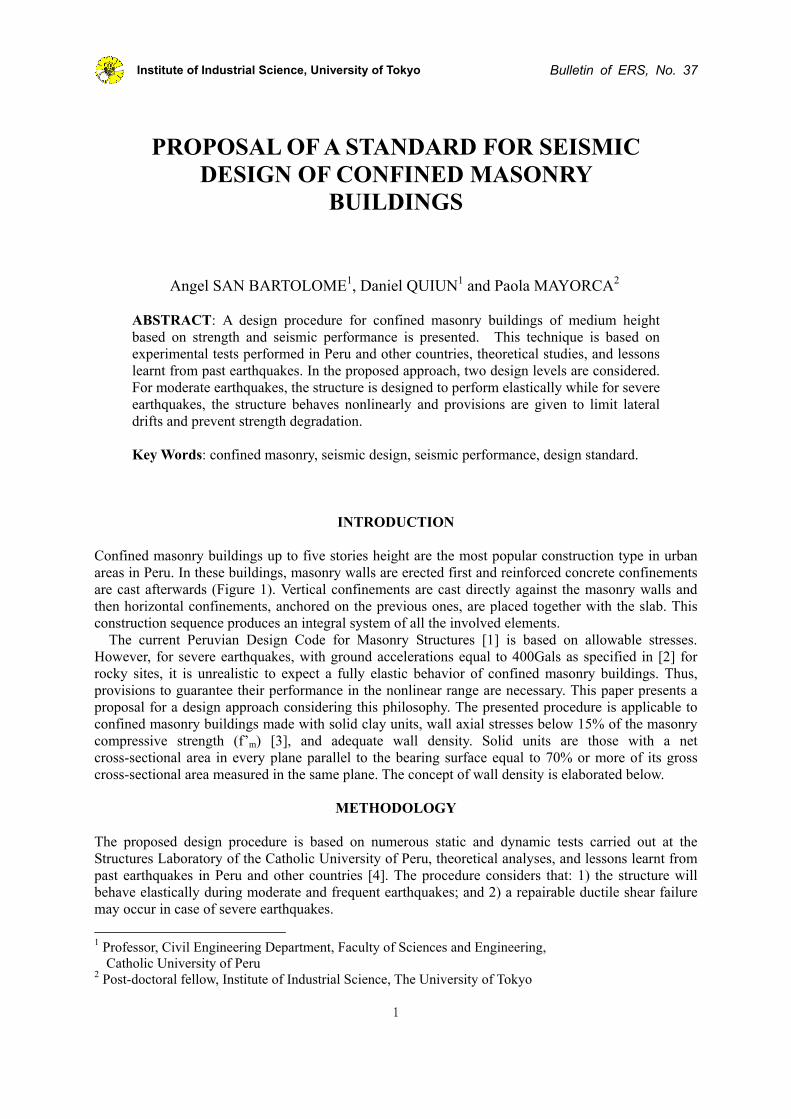
INTRODUCTION Confined masonry buildings up to five stories height are the most popular construction type in urban areas in Peru. In these buildings, masonry walls are erected first and reinforced concrete confinements are cast afterwards (Figure 1). Vertical confinements are cast directly against the masonry walls and then horizontal confinements, anchored on the previous ones, are placed together with the slab. This construction sequence produces an integral system of all the involved elements.
The current Peruvian Design Code for Masonry Structures [1] is based on allowable stresses. However, for severe earthquakes, with ground accelerations equal to 400Gals as specified in [2] for rocky sites, it is unrealistic to expect a fully elastic behavior of confined masonry buildings. Thus, provisions to guarantee their performance in the nonlinear range are necessary. This paper presents a proposal for a design approach considering this philosophy. The presented procedure is applicable to confined masonry buildings made with solid clay units, wall axial stresses below 15% of the masonry compressive strength (f’m) [3], and adequate wall density. Solid units are those with a net cross-sectional area in every plane parallel to the bearing surface equal to 70% or more of its gross cross-sectional area measured in the same plane. The concept of wall density is elaborated below.
METHODOLOGY The proposed design procedure is based on numerous static and dynamic tests carried out at the Structures Laboratory of the Catholic University of Peru, theoretical analyses, and lessons learnt from past earthquakes in Peru and other countries [4]. The procedure considers that: 1) the structure will behave elastically during moderate and frequent earthquakes; and 2) a repairable ductile shear failure may occur in case of severe earthquakes.
1 Professor, Civil Engineering Department, Faculty of Sciences and Engineering,
Catholic University of Peru 2 Post-doctoral fellow, Institute of Industrial Science, The University of Tokyo
1
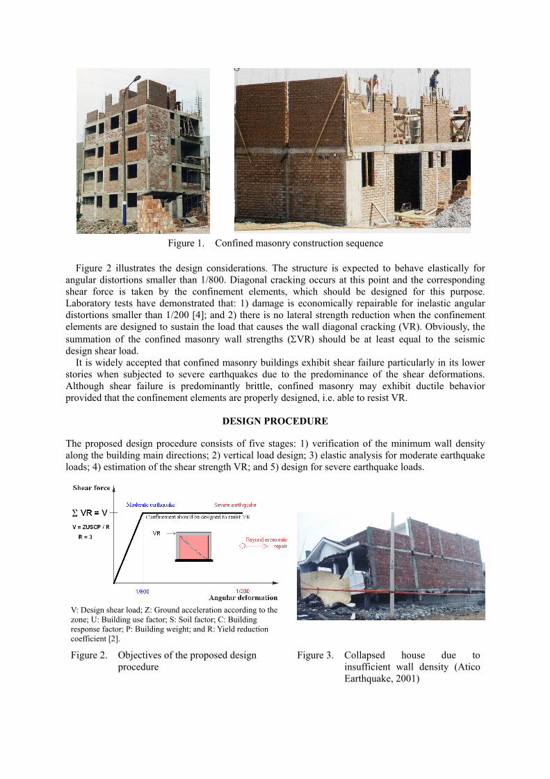
Figure 1. Confined masonry construction sequence
Figure 2 illustrates the design considerations. The structure is expected to behave elastically for
angular distortions smaller than 1/800. Diagonal cracking occurs at this point and the corresponding shear force is taken by the confinement elements, which should be designed for this purpose. Laboratory tests have demonstrated that: 1) damage is economically repairable for inelastic angular distortions smaller than 1/200 [4]; and 2) there is no lateral strength reduction when the confinement elements are designed to sustain the load that causes the wall diagonal cracking (VR). Obviously, the summation of the confined masonry wall strengths (ΣVR) should be at least equal to the seismic design shear load.
It is widely accepted that confined masonry buildings exhibit shear failure particularly in its lower stories when subjected to severe earthquakes due to the predominance of the shear deformations. Although shear failure is predominantly brittle, confined masonry may exhibit ductile behavior provided that the confinement elements are properly designed, i.e. able to resist VR.
DESIGN PROCEDURE
The proposed design procedure consists of five stages: 1) verification of the minimum wall density along the building main directions; 2) vertical load design; 3) elastic analysis for moderate earthquake loads; 4) estimation of the shear strength VR; and 5) design for severe earthquake loads.
V: Design shear load; Z: Ground acceleration according to the zone; U: Building use factor; S: Soil factor; C: Building response factor; P: Building weight; and R: Yield reduction coefficient [2].
Figure 2. Objectives of the proposed design procedure
Figure 3. Collapsed house due to insufficient wall density (Atico Earthquake, 2001)
Verification of the minimum wall density In order to avoid a brittle failure due to insufficient lateral strength or excessive ductility demand (Figure 3), a minimum wall density should be provided in each of the building main directions as specified in Eq.1:
56NSUZ
AtL
p
≥Σ Eq.1
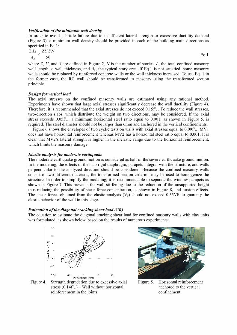
where Z, U, and S are defined in Figure 2, N is the number of stories, L, the total confined masonry wall length, t, wall thickness, and Ap, the typical story area. If Eq.1 is not satisfied, some masonry walls should be replaced by reinforced concrete walls or the wall thickness increased. To use Eq. 1 in the former case, the RC wall should be transformed to masonry using the transformed section principle. Design for vertical load The axial stresses on the confined masonry walls are estimated using any rational method. Experiments have shown that large axial stresses significantly decrease the wall ductility (Figure 4). Therefore, it is recommended that the axial stresses do not exceed 0.15f’m. To reduce the wall stresses, two-direction slabs, which distribute the weight on two directions, may be considered. If the axial stress exceeds 0.05f’m, a minimum horizontal steel ratio equal to 0.001, as shown in Figure 5, is required. The steel diameter should not be larger than 6mm and anchored in the vertical confinements.
Figure 6 shows the envelopes of two cyclic tests on walls with axial stresses equal to 0.09f’m. MV1 does not have horizontal reinforcement whereas MV2 has a horizontal steel ratio equal to 0.001. It is clear that MV2’s lateral strength is higher in the inelastic range due to the horizontal reinforcement, which limits the masonry damage. Elastic analysis for moderate earthquake The moderate earthquake ground motion is considered as half of the severe earthquake ground motion. In the modeling, the effects of the slab rigid diaphragm, parapets integral with the structure, and walls perpendicular to the analyzed direction should be considered. Because the confined masonry walls consist of two different materials, the transformed section criterion may be used to homogenize the structure. In order to simplify the modeling, it is recommendable to separate the window parapets as shown in Figure 7. This prevents the wall stiffening due to the reduction of the unsupported height thus reducing the possibility of shear force concentration, as shown in Figure 8, and torsion effects. The shear forces obtained from the elastic analysis (Ve) should not exceed 0.55VR to guaranty the elastic behavior of the wall in this stage.
Estimation of the diagonal cracking shear load (VR) The equation to estimate the diagonal cracking shear load for confined masonry walls with clay units was formulated, as shown below, based on the results of numerous experiments:
Figure 4. Strength degradation due to excessive axial
stress (0.14f’m) – Wall without horizontal reinforcement in the joints.
Figure 5. Horizontal reinforcement anchored to the vertical confinement.
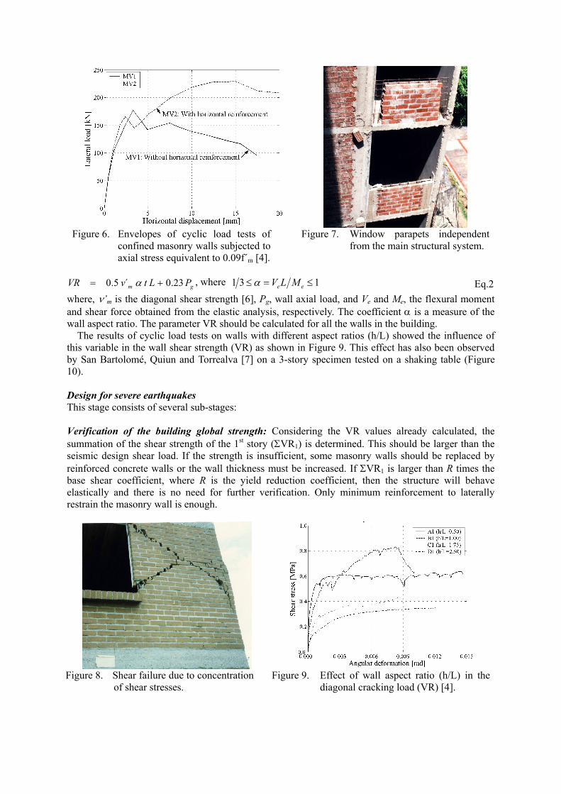
Figure 6. Envelopes of cyclic load tests of
confined masonry walls subjected to axial stress equivalent to 0.09f´m [4].
Figure 7. Window parapets independent from the main structural system.
gm PLtvVR 23.0´5.0 += α , where 131 ≤=≤ ee MLVα Eq.2
where, ν’m is the diagonal shear strength [6], Pg, wall axial load, and Ve and Me, the flexural moment and shear force obtained from the elastic analysis, respectively. The coefficient α is a measure of the wall aspect ratio. The parameter VR should be calculated for all the walls in the building.
The results of cyclic load tests on walls with different aspect ratios (h/L) showed the influence of this variable in the wall shear strength (VR) as shown in Figure 9. This effect has also been observed by San Bartolomé, Quiun and Torrealva [7] on a 3-story specimen tested on a shaking table (Figure 10).
Design for severe earthquakes This stage consists of several sub-stages: Verification of the building global strength: Considering the VR values already calculated, the summation of the shear strength of the 1st story (ΣVR1) is determined. This should be larger than the seismic design shear load. If the strength is insufficient, some masonry walls should be replaced by reinforced concrete walls or the wall thickness must be increased. If ΣVR1 is larger than R times the base shear coefficient, where R is the yield reduction coefficient, then the structure will behave elastically and there is no need for further verification. Only minimum reinforcement to laterally restrain the masonry wall is enough.
Figure 8. Shear failure due to concentration
of shear stresses. Figure 9. Effect of wall aspect ratio (h/L) in the
diagonal cracking load (VR) [4].
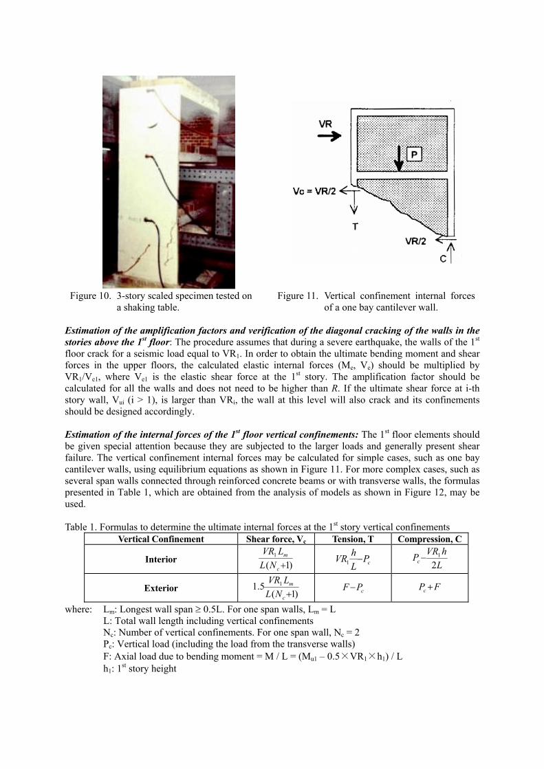
Figure 10. 3-story scaled specimen tested on a shaking table.
Figure 11. Vertical confinement internal forces of a one bay cantilever wall.
Estimation of the amplification factors and verification of the diagonal cracking of the walls in the stories above the 1st floor: The procedure assumes that during a severe earthquake, the walls of the 1st floor crack for a seismic load equal to VR1. In order to obtain the ultimate bending moment and shear forces in the upper floors, the calculated elastic internal forces (Me, Ve) should be multiplied by VR1/Ve1, where Ve1 is the elastic shear force at the 1st story. The amplification factor should be calculated for all the walls and does not need to be higher than R. If the ultimate shear force at i-th story wall, Vui (i > 1), is larger than VRi, the wall at this level will also crack and its confinements should be designed accordingly.
Estimation of the internal forces of the 1st floor vertical confinements: The 1st floor elements should be given special attention because they are subjected to the larger loads and generally present shear failure. The vertical confinement internal forces may be calculated for simple cases, such as one bay cantilever walls, using equilibrium equations as shown in Figure 11. For more complex cases, such as several span walls connected through reinforced concrete beams or with transverse walls, the formulas presented in Table 1, which are obtained from the analysis of models as shown in Figure 12, may be used. Table 1. Formulas to determine the ultimate internal forces at the 1st story vertical confinements
Vertical Confinement Shear force, Vc Tension, T Compression, C
Interior )1(1
+c
m
NLLVR
cPLhVR −1
LhVRPc 2
1−
Exterior )1(5.1 1
+c
m
NLLVR
cPF− FPc +
where: Lm: Longest wall span ≥ 0.5L. For one span walls, Lm = L L: Total wall length including vertical confinements Nc: Number of vertical confinements. For one span wall, Nc = 2 Pc: Vertical load (including the load from the transverse walls) F: Axial load due to bending moment = M / L = (Mu1 – 0.5×VR1×h1) / L h1: 1st story height
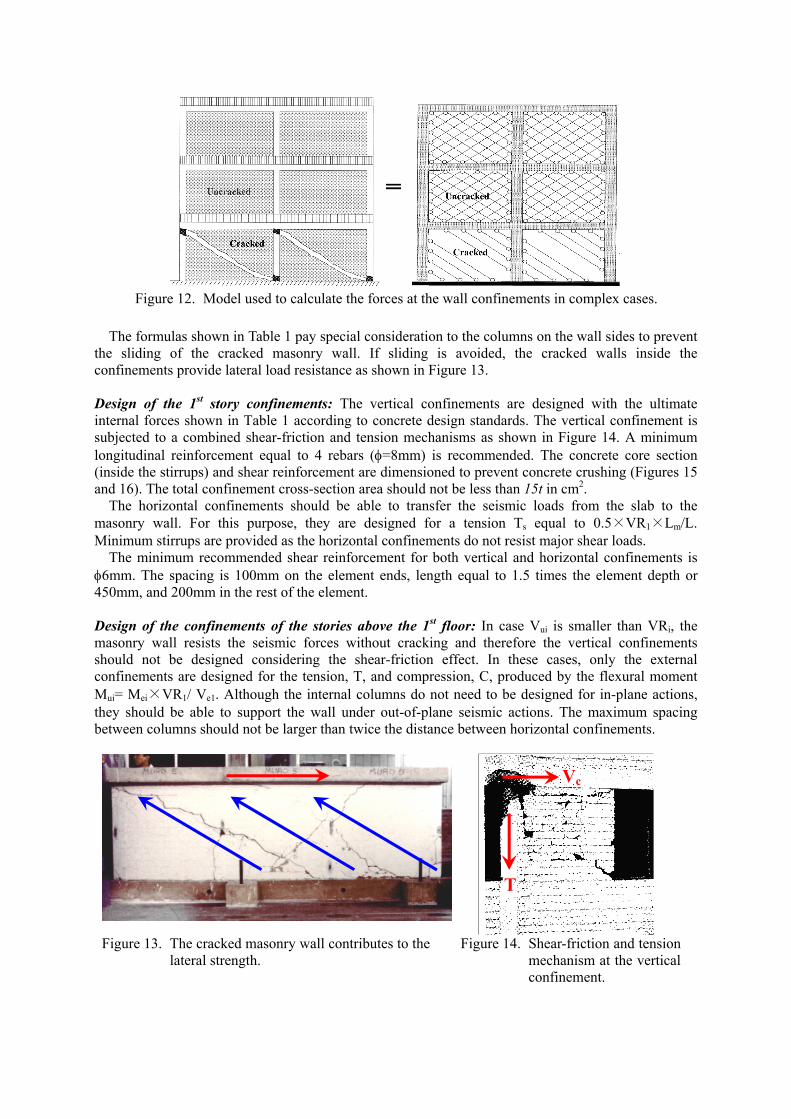
Figure 12. Model used to calculate the forces at the wall confinements in complex cases.
The formulas shown in Table 1 pay special consideration to the columns on the wall sides to prevent
the sliding of the cracked masonry wall. If sliding is avoided, the cracked walls inside the confinements provide lateral load resistance as shown in Figure 13. Design of the 1st story confinements: The vertical confinements are designed with the ultimate internal forces shown in Table 1 according to concrete design standards. The vertical confinement is subjected to a combined shear-friction and tension mechanisms as shown in Figure 14. A minimum longitudinal reinforcement equal to 4 rebars (φ=8mm) is recommended. The concrete core section (inside the stirrups) and shear reinforcement are dimensioned to prevent concrete crushing (Figures 15 and 16). The total confinement cross-section area should not be less than 15t in cm2.
The horizontal confinements should be able to transfer the seismic loads from the slab to the masonry wall. For this purpose, they are designed for a tension Ts equal to 0.5×VR1×Lm/L. Minimum stirrups are provided as the horizontal confinements do not resist major shear loads.
The minimum recommended shear reinforcement for both vertical and horizontal confinements is φ6mm. The spacing is 100mm on the element ends, length equal to 1.5 times the element depth or 450mm, and 200mm in the rest of the element.
Design of the confinements of the stories above the 1st floor: In case Vui is smaller than VRi, the masonry wall resists the seismic forces without cracking and therefore the vertical confinements should not be designed considering the shear-friction effect. In these cases, only the external confinements are designed for the tension, T, and compression, C, produced by the flexural moment Mui= Mei×VR1/ Ve1. Although the internal columns do not need to be designed for in-plane actions, they should be able to support the wall under out-of-plane seismic actions. The maximum spacing between columns should not be larger than twice the distance between horizontal confinements.
Figure 13. The cracked masonry wall contributes to the
lateral strength. Figure 14. Shear-friction and tension
mechanism at the vertical confinement.
Vc
T
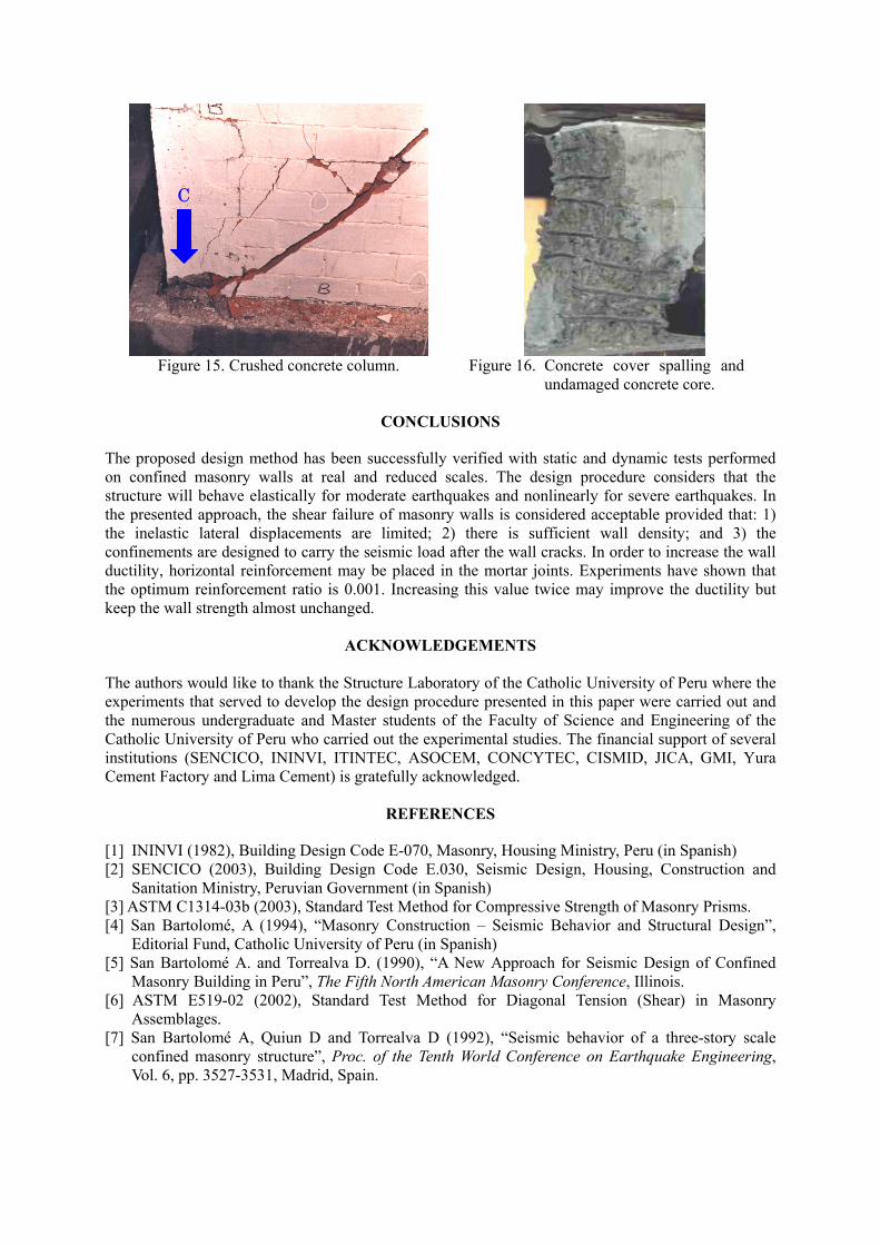
Figure 15. Crushed concrete column. Figure 16. Concrete cover spalling and
undamaged concrete core.
C
CONCLUSIONS
The proposed design method has been successfully verified with static and dynamic tests performed on confined masonry walls at real and reduced scales. The design procedure considers that the structure will behave elastically for moderate earthquakes and nonlinearly for severe earthquakes. In the presented approach, the shear failure of masonry walls is considered acceptable provided that: 1) the inelastic lateral displacements are limited; 2) there is sufficient wall density; and 3) the confinements are designed to carry the seismic load after the wall cracks. In order to increase the wall ductility, horizontal reinforcement may be placed in the mortar joints. Experiments have shown that the optimum reinforcement ratio is 0.001. Increasing this value twice may improve the ductility but keep the wall strength almost unchanged.
ACKNOWLEDGEMENTS
The authors would like to thank the Structure Laboratory of the Catholic University of Peru where the experiments that served to develop the design procedure presented in this paper were carried out and the numerous undergraduate and Master students of the Faculty of Science and Engineering of the Catholic University of Peru who carried out the experimental studies. The financial support of several institutions (SENCICO, ININVI, ITINTEC, ASOCEM, CONCYTEC, CISMID, JICA, GMI, Yura Cement Factory and Lima Cement) is gratefully acknowledged.
REFERENCES [1] ININVI (1982), Building Design Code E-070, Masonry, Housing Ministry, Peru (in Spanish) [2] SENCICO (2003), Building Design Code E.030, Seismic Design, Housing, Construction and
Sanitation Ministry, Peruvian Government (in Spanish) [3] ASTM C1314-03b (2003), Standard Test Method for Compressive Strength of Masonry Prisms. [4] San Bartolomé, A (1994), “Masonry Construction – Seismic Behavior and Structural Design”,
Editorial Fund, Catholic University of Peru (in Spanish) [5] San Bartolomé A. and Torrealva D. (1990), “A New Approach for Seismic Design of Confined
Masonry Building in Peru”, The Fifth North American Masonry Conference, Illinois. [6] ASTM E519-02 (2002), Standard Test Method for Diagonal Tension (Shear) in Masonry
Assemblages. [7] San Bartolomé A, Quiun D and Torrealva D (1992), “Seismic behavior of a three-story scale
confined masonry structure”, Proc. of the Tenth World Conference on Earthquake Engineering, Vol. 6, pp. 3527-3531, Madrid, Spain.